JP6284803B2 - Injection molding machine - Google Patents
Injection molding machineDownload PDFInfo
- Publication number
- JP6284803B2 JP6284803B2JP2014070442AJP2014070442AJP6284803B2JP 6284803 B2JP6284803 B2JP 6284803B2JP 2014070442 AJP2014070442 AJP 2014070442AJP 2014070442 AJP2014070442 AJP 2014070442AJP 6284803 B2JP6284803 B2JP 6284803B2
- Authority
- JP
- Japan
- Prior art keywords
- mold
- light
- molding material
- deterioration
- injection
- Prior art date
- Legal status (The legal status is an assumption and is not a legal conclusion. Google has not performed a legal analysis and makes no representation as to the accuracy of the status listed.)
- Active
Links
- 238000001746injection mouldingMethods0.000titleclaimsdescription23
- 239000012778molding materialSubstances0.000claimsdescription52
- 238000001514detection methodMethods0.000claimsdescription44
- 230000006866deteriorationEffects0.000claimsdescription36
- 238000002347injectionMethods0.000claimsdescription29
- 239000007924injectionSubstances0.000claimsdescription29
- 238000000465mouldingMethods0.000claimsdescription15
- 238000010438heat treatmentMethods0.000claimsdescription3
- 230000001678irradiating effectEffects0.000claimsdescription3
- 238000007493shaping processMethods0.000claims1
- 230000007246mechanismEffects0.000description8
- 230000015556catabolic processEffects0.000description5
- 238000006243chemical reactionMethods0.000description5
- 238000006731degradation reactionMethods0.000description5
- 239000007788liquidSubstances0.000description3
- 230000007423decreaseEffects0.000description2
- 230000002950deficientEffects0.000description2
- 230000031700light absorptionEffects0.000description2
- 230000003287optical effectEffects0.000description2
- 238000002834transmittanceMethods0.000description2
- 230000007547defectEffects0.000description1
- 230000006870functionEffects0.000description1
- 238000007689inspectionMethods0.000description1
- 238000000034methodMethods0.000description1
- 238000012986modificationMethods0.000description1
- 230000004048modificationEffects0.000description1
- 239000013307optical fiberSubstances0.000description1
- 230000008569processEffects0.000description1
- 230000001141propulsive effectEffects0.000description1
- 238000005303weighingMethods0.000description1
Images

Classifications
- B—PERFORMING OPERATIONS; TRANSPORTING
- B29—WORKING OF PLASTICS; WORKING OF SUBSTANCES IN A PLASTIC STATE IN GENERAL
- B29C—SHAPING OR JOINING OF PLASTICS; SHAPING OF MATERIAL IN A PLASTIC STATE, NOT OTHERWISE PROVIDED FOR; AFTER-TREATMENT OF THE SHAPED PRODUCTS, e.g. REPAIRING
- B29C45/00—Injection moulding, i.e. forcing the required volume of moulding material through a nozzle into a closed mould; Apparatus therefor
- B29C45/17—Component parts, details or accessories; Auxiliary operations
- B29C45/76—Measuring, controlling or regulating
- B29C45/768—Detecting defective moulding conditions
- B—PERFORMING OPERATIONS; TRANSPORTING
- B29—WORKING OF PLASTICS; WORKING OF SUBSTANCES IN A PLASTIC STATE IN GENERAL
- B29C—SHAPING OR JOINING OF PLASTICS; SHAPING OF MATERIAL IN A PLASTIC STATE, NOT OTHERWISE PROVIDED FOR; AFTER-TREATMENT OF THE SHAPED PRODUCTS, e.g. REPAIRING
- B29C45/00—Injection moulding, i.e. forcing the required volume of moulding material through a nozzle into a closed mould; Apparatus therefor
- B29C45/0025—Preventing defects on the moulded article, e.g. weld lines, shrinkage marks
- B—PERFORMING OPERATIONS; TRANSPORTING
- B29—WORKING OF PLASTICS; WORKING OF SUBSTANCES IN A PLASTIC STATE IN GENERAL
- B29C—SHAPING OR JOINING OF PLASTICS; SHAPING OF MATERIAL IN A PLASTIC STATE, NOT OTHERWISE PROVIDED FOR; AFTER-TREATMENT OF THE SHAPED PRODUCTS, e.g. REPAIRING
- B29C45/00—Injection moulding, i.e. forcing the required volume of moulding material through a nozzle into a closed mould; Apparatus therefor
- B29C45/03—Injection moulding apparatus
- B—PERFORMING OPERATIONS; TRANSPORTING
- B29—WORKING OF PLASTICS; WORKING OF SUBSTANCES IN A PLASTIC STATE IN GENERAL
- B29C—SHAPING OR JOINING OF PLASTICS; SHAPING OF MATERIAL IN A PLASTIC STATE, NOT OTHERWISE PROVIDED FOR; AFTER-TREATMENT OF THE SHAPED PRODUCTS, e.g. REPAIRING
- B29C45/00—Injection moulding, i.e. forcing the required volume of moulding material through a nozzle into a closed mould; Apparatus therefor
- B29C45/17—Component parts, details or accessories; Auxiliary operations
- B29C45/64—Mould opening, closing or clamping devices
- B—PERFORMING OPERATIONS; TRANSPORTING
- B29—WORKING OF PLASTICS; WORKING OF SUBSTANCES IN A PLASTIC STATE IN GENERAL
- B29C—SHAPING OR JOINING OF PLASTICS; SHAPING OF MATERIAL IN A PLASTIC STATE, NOT OTHERWISE PROVIDED FOR; AFTER-TREATMENT OF THE SHAPED PRODUCTS, e.g. REPAIRING
- B29C45/00—Injection moulding, i.e. forcing the required volume of moulding material through a nozzle into a closed mould; Apparatus therefor
- B29C45/17—Component parts, details or accessories; Auxiliary operations
- B29C45/76—Measuring, controlling or regulating
- B29C45/7653—Measuring, controlling or regulating mould clamping forces
- B—PERFORMING OPERATIONS; TRANSPORTING
- B29—WORKING OF PLASTICS; WORKING OF SUBSTANCES IN A PLASTIC STATE IN GENERAL
- B29C—SHAPING OR JOINING OF PLASTICS; SHAPING OF MATERIAL IN A PLASTIC STATE, NOT OTHERWISE PROVIDED FOR; AFTER-TREATMENT OF THE SHAPED PRODUCTS, e.g. REPAIRING
- B29C2945/00—Indexing scheme relating to injection moulding, i.e. forcing the required volume of moulding material through a nozzle into a closed mould
- B29C2945/76—Measuring, controlling or regulating
- B29C2945/76003—Measured parameter
- B29C2945/76013—Force
- B—PERFORMING OPERATIONS; TRANSPORTING
- B29—WORKING OF PLASTICS; WORKING OF SUBSTANCES IN A PLASTIC STATE IN GENERAL
- B29C—SHAPING OR JOINING OF PLASTICS; SHAPING OF MATERIAL IN A PLASTIC STATE, NOT OTHERWISE PROVIDED FOR; AFTER-TREATMENT OF THE SHAPED PRODUCTS, e.g. REPAIRING
- B29C2945/00—Indexing scheme relating to injection moulding, i.e. forcing the required volume of moulding material through a nozzle into a closed mould
- B29C2945/76—Measuring, controlling or regulating
- B29C2945/76177—Location of measurement
- B29C2945/76224—Closure or clamping unit
- B29C2945/76234—Closure or clamping unit tie-bars
- B—PERFORMING OPERATIONS; TRANSPORTING
- B29—WORKING OF PLASTICS; WORKING OF SUBSTANCES IN A PLASTIC STATE IN GENERAL
- B29C—SHAPING OR JOINING OF PLASTICS; SHAPING OF MATERIAL IN A PLASTIC STATE, NOT OTHERWISE PROVIDED FOR; AFTER-TREATMENT OF THE SHAPED PRODUCTS, e.g. REPAIRING
- B29C2945/00—Indexing scheme relating to injection moulding, i.e. forcing the required volume of moulding material through a nozzle into a closed mould
- B29C2945/76—Measuring, controlling or regulating
- B29C2945/76344—Phase or stage of measurement
- B29C2945/76391—Mould clamping, compression of the cavity
- B—PERFORMING OPERATIONS; TRANSPORTING
- B29—WORKING OF PLASTICS; WORKING OF SUBSTANCES IN A PLASTIC STATE IN GENERAL
- B29C—SHAPING OR JOINING OF PLASTICS; SHAPING OF MATERIAL IN A PLASTIC STATE, NOT OTHERWISE PROVIDED FOR; AFTER-TREATMENT OF THE SHAPED PRODUCTS, e.g. REPAIRING
- B29C2945/00—Indexing scheme relating to injection moulding, i.e. forcing the required volume of moulding material through a nozzle into a closed mould
- B29C2945/76—Measuring, controlling or regulating
- B29C2945/76344—Phase or stage of measurement
- B29C2945/76414—Solidification, setting phase
- B—PERFORMING OPERATIONS; TRANSPORTING
- B29—WORKING OF PLASTICS; WORKING OF SUBSTANCES IN A PLASTIC STATE IN GENERAL
- B29C—SHAPING OR JOINING OF PLASTICS; SHAPING OF MATERIAL IN A PLASTIC STATE, NOT OTHERWISE PROVIDED FOR; AFTER-TREATMENT OF THE SHAPED PRODUCTS, e.g. REPAIRING
- B29C2945/00—Indexing scheme relating to injection moulding, i.e. forcing the required volume of moulding material through a nozzle into a closed mould
- B29C2945/76—Measuring, controlling or regulating
- B29C2945/76451—Measurement means
- B29C2945/76461—Optical, e.g. laser
- B—PERFORMING OPERATIONS; TRANSPORTING
- B29—WORKING OF PLASTICS; WORKING OF SUBSTANCES IN A PLASTIC STATE IN GENERAL
- B29C—SHAPING OR JOINING OF PLASTICS; SHAPING OF MATERIAL IN A PLASTIC STATE, NOT OTHERWISE PROVIDED FOR; AFTER-TREATMENT OF THE SHAPED PRODUCTS, e.g. REPAIRING
- B29C2945/00—Indexing scheme relating to injection moulding, i.e. forcing the required volume of moulding material through a nozzle into a closed mould
- B29C2945/76—Measuring, controlling or regulating
- B29C2945/76929—Controlling method
- B29C2945/76939—Using stored or historical data sets
- B29C2945/76946—Using stored or historical data sets using an expert system, i.e. the system possesses a database in which human experience is stored, e.g. to help interfering the possible cause of a fault
Landscapes
- Engineering & Computer Science (AREA)
- Manufacturing & Machinery (AREA)
- Mechanical Engineering (AREA)
- Injection Moulding Of Plastics Or The Like (AREA)
- Moulds For Moulding Plastics Or The Like (AREA)
Description
Translated fromJapanese本発明は、射出成形機に関する。 The present invention relates to an injection molding machine.
射出成形機は、金型装置の型閉、型締、型開を行う型締装置、金型装置内のキャビティ空間に成形材料を充填する射出装置、金型装置内の成形品を突き出すエジェクタ装置を備える(例えば、特許文献1参照)。 An injection molding machine includes a mold clamping device that performs mold closing, mold clamping, and mold opening of a mold device, an injection device that fills a cavity space in the mold device with a molding material, and an ejector device that projects a molded product in the mold device. (For example, refer to Patent Document 1).
従来、射出成形後の外観検査によって成形の良否が判別されていた。 Conventionally, the quality of molding has been determined by appearance inspection after injection molding.
本発明は、上記課題に鑑みてなされたものであって、射出成形時に成形の良否を判別できる、射出成形機の提供を主な目的とする。 The present invention has been made in view of the above problems, and a main object of the present invention is to provide an injection molding machine that can determine the quality of molding at the time of injection molding.
上記課題を解決するため、本発明の一態様によれば、
金型装置の型閉、型締、型開を行う型締装置と、
前記金型装置内に成形材料を充填する射出装置であって、前記成形材料を加熱するシリンダと、前記シリンダの前端に設けられるノズルとを有する射出装置と、
前記ノズル内における前記成形材料からの光の強度を検出する充填前光強度検出部と、
前記金型装置内に充填された前記成形材料からの光の強度を検出する充填後光強度検出部と、
前記充填前光強度検出部の検出値に基づき前記ノズル内における前記成形材料の劣化を検出すると共に、前記充填後光強度検出部の検出値に基づき前記金型装置内に充填された前記成形材料の劣化を検出する劣化検出部とを備え、
前記劣化検出部は、ショット毎に、前記ノズル内における前記成形材料の劣化度および前記金型装置内に充填された前記成形材料の劣化度に基づき、成形の良否を判別する、射出成形機が提供される。In order to solve the above problems, according to one aspect of the present invention,
A mold clamping device that performs mold closing, mold clamping and mold opening of the mold device;
An injection device for filling a molding material into the mold device, the injection devicehaving a cylinder for heating the molding material, and a nozzle provided at a front end of the cylinder ;
Apre-filling light intensity detector that detects the intensity of light from the molding materialin the nozzle;
A post-filling light intensity detector that detects the intensity of light from the molding material filled in the mold apparatus;
The molding material filled in the mold apparatus based on the detection value of the post-filling light intensity detection unit while detecting deterioration of the molding material in the nozzle based on the detection value of the pre-filling light intensity detection unit A deterioration detecting unit for detecting deterioration of
An injection molding machinethat determines the quality of molding for each shot based on a degree of degradation of the molding material in the nozzle and a degree of degradation of the molding material filled in the mold apparatus for each shot; Provided.
本発明の一態様によれば、射出成形時に成形の良否を判別できる、射出成形機が提供される。 According to one aspect of the present invention, an injection molding machine that can determine whether molding is good or not during injection molding is provided.
以下、本発明を実施するための形態について図面を参照して説明するが、各図面において、同一の又は対応する構成については同一の又は対応する符号を付して説明を省略する。 DESCRIPTION OF EMBODIMENTS Hereinafter, embodiments for carrying out the present invention will be described with reference to the drawings. In each of the drawings, the same or corresponding components are denoted by the same or corresponding reference numerals, and description thereof will be omitted.
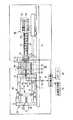
図1は、本発明の一実施形態による射出成形機の型締時の状態を示す図である。図2は、本発明の一実施形態による射出成形機の型開完了時の状態を示す図である。図1および図2に示すように、射出成形機は、フレームFr、型締装置10、射出装置50、エジェクタ装置60、第1光照射部71、第1光強度検出部72、第2光照射部73、第2光強度検出部74、および劣化検出部76を有する。 FIG. 1 is a view showing a state at the time of mold clamping of an injection molding machine according to an embodiment of the present invention. FIG. 2 is a view showing a state at the completion of mold opening of the injection molding machine according to the embodiment of the present invention. As shown in FIGS. 1 and 2, the injection molding machine includes a frame Fr, a
型締装置10は、金型装置30の型閉、型締、型開を行う。型締装置10は、例えば図1に示すように、固定プラテン12、可動プラテン13、リヤプラテン15、タイバー16、トグル機構20、および型締モータ26を有する。型締装置10の説明では、型閉時の可動プラテン13の移動方向(図1中右方向)を前方とし、型開時の可動プラテン13の移動方向(図1中左方向)を後方として説明する。 The
固定プラテン12は、フレームFrに対して固定される。固定プラテン12における可動プラテン13との対向面に固定金型32が取り付けられる。 The
可動プラテン13は、フレームFr上に敷設されるガイド(例えばガイドレール)17に沿って移動自在とされ、固定プラテン12に対して進退自在とされる。可動プラテン13における固定プラテン12との対向面に可動金型33が取り付けられる。固定金型32と可動金型33とで金型装置30が構成される。 The
固定プラテン12に対して可動プラテン13を進退させることにより、金型装置30の型閉、型締、型開が行われる。 By moving the
リヤプラテン15は、複数本(例えば4本)のタイバー16を介して固定プラテン12と連結され、フレームFr上に型開閉方向に移動自在に載置される。尚、リヤプラテン15は、フレームFr上に敷設されるガイドに沿って移動自在とされてもよい。リヤプラテン15のガイドは、可動プラテン13のガイド17と共通のものでもよい。 The
尚、本実施形態では、固定プラテン12がフレームFrに対して固定され、リヤプラテン15がフレームFrに対して型開閉方向に移動自在とされるが、リヤプラテン15がフレームFrに対して固定され、固定プラテン12がフレームFrに対して型開閉方向に移動自在とされてもよい。 In this embodiment, the
タイバー16は、型開閉方向に平行とされ、型締力に応じて伸びる。少なくとも1本のタイバー16には型締力検出器が設けられる。型締力検出器は、歪みゲージ式であってよく、タイバーの歪みを検出することによって型締力を検出する。 The
尚、型締力検出器は、歪みゲージ式に限定されず、圧電式、容量式、油圧式、電磁式などでもよく、その取り付け位置もタイバー16に限定されない。 The clamping force detector is not limited to the strain gauge type, and may be a piezoelectric type, a capacitive type, a hydraulic type, an electromagnetic type, or the like, and the mounting position thereof is not limited to the
トグル機構20は、可動プラテン13とリヤプラテン15との間に配設され、可動プラテン13およびリヤプラテン15にそれぞれ取り付けられる。トグル機構20が型開閉方向に伸縮することにより、リヤプラテン15に対して可動プラテン13が進退する。 The
型締モータ26は、トグル機構20を介して可動プラテン13を移動させる。型締モータ26とトグル機構20との間には、型締モータ26の回転運動を直線運動に変換してトグル機構20に伝達する運動変換部27としてのボールねじ機構が設けられる。 The
型締モータ26が可動プラテン13を前進させることにより、型閉が行われる。型閉完了後、型締モータ26による推進力にトグル倍率を乗じた型締力が生じ、型締力によって型締が行われる。型締時に可動金型33と固定金型32との間にキャビティ空間34が形成され、キャビティ空間34に液状の成形材料が充填される。キャビティ空間34内の成形材料は、固化され、成形品となる。その後、型締モータ26は可動プラテン13を後退させることにより、型開が行われる。 The mold closing is performed by the
射出装置50は、金型装置30内に成形材料を充填する。射出装置50は、シリンダ51、スクリュ52、計量モータ53、および射出モータ54を有する。射出装置50の説明では、型締装置10の説明と異なり、充填時のスクリュ52の移動方向(図1中左方向)を前方とし、計量時のスクリュ52の移動方向(図1中右方向)を後方として説明する。 The
シリンダ51は供給口51aから供給された成形材料を加熱する。供給口51aはシリンダ51の後部に形成される。シリンダ51の外周には、ヒータなどの加熱源が設けられる。シリンダ51の前端にはノズル56が設けられる。 The
スクリュ52は、シリンダ51内において回転自在に且つ進退自在に配設される。 The
計量モータ53は、スクリュ52を回転させることにより、スクリュ52の螺旋状の溝に沿って成形材料を前方に送る。成形材料は、前方に送られながら、シリンダ51からの熱によって徐々に溶融される。液状の成形材料がスクリュ52の前方に送られシリンダ51の前部に蓄積されるにつれ、スクリュ52が後退させられる。 The
射出モータ54は、スクリュ52を前進させることにより、スクリュ52の前方に蓄積された液状の成形材料を金型装置30のキャビティ空間34に充填させる。その後、射出モータ54は、スクリュ52を前方に押し、キャビティ空間34内の成形材料に圧力をかける。ショートやヒケなどによる不足分の成形材料が補充できる。 The
尚、本実施形態の射出装置は、インライン・スクリュ方式であるが、プリプラ方式でもよい。プリプラ方式の射出装置は、可塑化シリンダ内で溶融された成形材料を射出シリンダに供給し、射出シリンダから金型装置内に成形材料を射出する。可塑化シリンダ内にはスクリュが回転自在にまたは回転自在に且つ進退自在に配設され、射出シリンダ内にはプランジャが進退自在に配設される。 In addition, although the injection apparatus of this embodiment is an inline screw system, a pre-plastic system may be used. A pre-plastic injection device supplies a molding material melted in a plasticizing cylinder to the injection cylinder, and injects the molding material from the injection cylinder into a mold device. In the plasticizing cylinder, a screw is rotatably or rotatably and reciprocally disposed, and in the injection cylinder, a plunger is reciprocally disposed.
エジェクタ装置60は、型開後の金型装置30から成形品を突き出す。エジェクタ装置60は、エジェクタロッド61、およびエジェクタモータ62を有する。エジェクタ装置60の説明では、型締装置10の説明と同様に、型閉時の可動プラテン13の移動方向(図1中右方向)を前方とし、型開時の可動プラテン13の移動方向(図1中左方向)を後方として説明する。 The
エジェクタロッド61は、可動プラテン13の貫通孔に挿通され、可動プラテン13に対して進退自在とされる。エジェクタロッド61の進退に伴って、可動金型33内に配設される突き出し部材35が進退され、突き出し部材35が可動金型33から成形品を突き出す。 The
エジェクタモータ62は、エジェクタロッド61を進退させる。エジェクタモータ62とエジェクタロッド61との間には、エジェクタモータ62の回転運動をエジェクタロッド61の直線運動に変換する運動変換部63が設けられる。運動変換部63は、例えばボールねじ機構などで構成される。 The
第1光照射部71は、金型装置30または型締装置10など(図1および図2では金型装置30)に取り付けられ、型開後の成形品に光を照射する。第1光照射部71からの光は、紫外線、可視光線、赤外線などのいずれでもよい。第1光照射部71からの光は、成形品を透過し、導光部材75に入射する。 The first
導光部材75は、光ファイバーなどで構成され、成形品からの光を第1光強度検出部72に導く。導光部材75は、例えば突き出し部材35の貫通孔やエジェクタロッド61の貫通孔に挿通されてよい。 The
第1光強度検出部72は、成形品からの光の強度を検出する。第1光強度検出部72は、光学フィルターや光電変換素子などで構成され、所定の波長範囲の光の強度を示す信号を劣化検出部76に出力する。 The first
尚、本実施形態の第1光強度検出部72は、型開後に成形品からの光を受光するが、型締中に金型装置30内の成形材料からの光を受光してもよい。この場合、第1光照射部71は、金型装置30内に取り付けられてよい。 The first
劣化検出部76は、メモリなどの記憶部およびCPU(Central Processing Unit)を有し、記憶部に記憶されるプログラムをCPUに実行させることにより、各種処理を行う。劣化検出部76は、射出成形機の各種動作を制御するコントローラとして機能してもよい。尚、コントローラは、劣化検出部76とは別に設けられてもよい。 The
劣化検出部76は、第1光強度検出部72の検出値に基づいて、成形材料の劣化を検出する。成形材料の熱劣化が進むほど、成形材料による光の吸収率が高く、光の透過率が低い。従って、劣化検出部76は、第1光強度検出部72の検出値に基づいて、成形材料の劣化の程度を検出できる。 The
劣化検出部76は、成形材料の劣化の程度に応じて成形の良否を判別してもよい。例えば、劣化検出部76は、基準値(例えば良品時の値)を記憶部に予め記憶しておき、基準値と検出値とを比較することにより成形の良否を判定する。劣化検出部76は、ショット毎に成形の良否を判別してよい。基準値の代わりに、前回のショットの値、過去数回のショットの平均値が用いられてもよい。 The
尚、本実施形態の第1光強度検出部72は、成形品の透過光を受光するが、成形品からの反射光、散乱光、発光光などのいずれを受光してもよい。発光光は、例えば紫外線を成形品の表面に照射することにより生じる。反射光、散乱光、発光光などの光の強度は、成形材料の劣化の程度に応じて変化する。 The first
尚、本実施形態の第1光照射部71は、射出成形機に備えられるが、射出成形機を設置する工場に備えられてもよい。また、第1光照射部71や第1光強度検出部72は、取出機に取り付けられてもよい。取出機は、型開後の金型装置30から成形品を取り出す。 In addition, although the 1st
第2光照射部73は、射出装置50に取り付けられ、射出装置50における成形材料に光を照射する。第2光照射部73からの光は、紫外線、可視光線、赤外線などのいずれでもよい。第2光照射部73からの光は、ノズル56内の溶融状態の成形材料を透過し、第2光強度検出部74に入射する。 The second
第2光強度検出部74は、射出装置50に取り付けられ、射出装置50における成形材料からの光の強度を検出する。第2光強度検出部74は、光学フィルターや光電変換素子などで構成され、所定の波長範囲の光の強度を示す信号を劣化検出部76に出力する。 The second light intensity detection unit 74 is attached to the
尚、第2光照射部73や第2光強度検出部74は、射出装置50のノズル56に取り付けられるが、射出装置50のシリンダ51に取り付けられてもよい。 In addition, although the 2nd
劣化検出部76は、第2光強度検出部74の検出値に基づいて、射出装置50における成形材料の劣化を検出する。成形材料の熱劣化が進むほど、成形材料による光の吸収率が高く、光の透過率が低い。従って、第2光強度検出部74の検出値に基づいて、成形材料の劣化の程度を検出することができる。 The
劣化検出部76は、射出装置50における成形材料の劣化の程度に応じて成形の良否を判別してもよい。例えば、劣化検出部76は、基準値(例えば良品時の値)を記憶部に予め記憶しておき、基準値と検出値とを比較することにより成形の良否を判別する。劣化検出部76は、ショット毎に成形の良否を判定してよい。基準値の代わりに、前回のショットの値、過去数回のショットの平均値が用いられてもよい。 The
尚、本実施形態の第2光強度検出部74は、射出装置50における成形材料の透過光を受光するが、射出装置50における成形材料からの反射光、散乱光、発光光などのいずれを受光してもよい。発光光は、例えば紫外線を成形材料の表面に照射することにより生じる。反射光、散乱光、発光光などの光の強度は、成形材料の劣化の程度に応じて変化する。 The second light intensity detector 74 of the present embodiment receives the transmitted light of the molding material in the
画像表示装置78は、劣化検出部76の検出結果(劣化の程度、成形の良否など)を表示してよい。 The
劣化検出部76が成形不良を検出する場合、画像表示装置78やスピーカー80などの出力装置がアラームを出力してよい。また、劣化検出部76が成形不良を検出する場合、射出成形機の成形動作が中断されてもよい。 When the
以上、射出成形機などの実施形態について説明したが、本発明は上記実施形態等に限定されるものではなく、特許請求の範囲に記載された本発明の要旨の範囲内において、種々の変形、改良が可能である。 The embodiments of the injection molding machine and the like have been described above. However, the present invention is not limited to the above-described embodiments and the like, and various modifications can be made within the scope of the gist of the present invention described in the claims. Improvements are possible.
例えば、射出成形機はビームスプリッターを有してもよい。ビームスプリッターは、光照射部からの光の一部を透過させて成形材料に照射すると共に、成形材料からの光の一部を反射させて光強度検出部に当てる。 For example, the injection molding machine may have a beam splitter. The beam splitter transmits a part of the light from the light irradiation unit to irradiate the molding material, and reflects a part of the light from the molding material to hit the light intensity detection unit.
10 型締装置
11 フレーム
12 固定プラテン
13 可動プラテン
26 型締モータ
30 金型装置
32 固定金型
33 可動金型
34 キャビティ空間
50 射出装置
51 シリンダ
52 スクリュ
53 計量モータ
54 射出モータ
56 ノズル
60 エジェクタ装置
61 エジェクタロッド
62 エジェクタモータ
71 第1光照射部
72 第1光強度検出部
73 第2光照射部
74 第2光強度検出部
76 劣化検出部10 Mold clamping device 11
Claims (3)
Translated fromJapanese前記金型装置内に成形材料を充填する射出装置であって、前記成形材料を加熱するシリンダと、前記シリンダの前端に設けられるノズルとを有する射出装置と、
前記ノズル内における前記成形材料からの光の強度を検出する充填前光強度検出部と、
前記金型装置内に充填された前記成形材料からの光の強度を検出する充填後光強度検出部と、
前記充填前光強度検出部の検出値に基づき前記ノズル内における前記成形材料の劣化を検出すると共に、前記充填後光強度検出部の検出値に基づき前記金型装置内に充填された前記成形材料の劣化を検出する劣化検出部とを備え、
前記劣化検出部は、ショット毎に、前記ノズル内における前記成形材料の劣化度および前記金型装置内に充填された前記成形材料の劣化度に基づき、成形の良否を判別する、射出成形機。A mold clamping device that performs mold closing, mold clamping and mold opening of the mold device;
An injection device for filling a molding material into the mold device, the injection devicehaving a cylinder for heating the molding material, and a nozzle provided at a front end of the cylinder ;
Apre-filling light intensity detector that detects the intensity of light from the molding materialin the nozzle;
A post-filling light intensity detector that detects the intensity of light from the molding material filled in the mold apparatus;
The molding material filled in the mold apparatus based on the detection value of the post-filling light intensity detection unit while detecting deterioration of the molding material in the nozzle based on the detection value of the pre-filling light intensity detection unit A deterioration detecting unit for detecting deterioration of
The said deterioration detection part is an injection molding machinewhich discriminate | determines the quality of shaping | molding for every shot based on the deterioration degree of the said molding material in the said nozzle, and the deterioration degree of the said molding material with which the mold apparatus was filled .
Priority Applications (4)
| Application Number | Priority Date | Filing Date | Title |
|---|---|---|---|
| JP2014070442AJP6284803B2 (en) | 2014-03-28 | 2014-03-28 | Injection molding machine |
| TW104107903ATWI670162B (en) | 2014-03-28 | 2015-03-12 | Injection molding machine |
| KR1020150036503AKR101714863B1 (en) | 2014-03-28 | 2015-03-17 | Injection molding machine |
| CN201510124861.5ACN104943112B (en) | 2014-03-28 | 2015-03-20 | Injection (mo(u)lding) machine |
Applications Claiming Priority (1)
| Application Number | Priority Date | Filing Date | Title |
|---|---|---|---|
| JP2014070442AJP6284803B2 (en) | 2014-03-28 | 2014-03-28 | Injection molding machine |
Publications (2)
| Publication Number | Publication Date |
|---|---|
| JP2015189211A JP2015189211A (en) | 2015-11-02 |
| JP6284803B2true JP6284803B2 (en) | 2018-02-28 |
Family
ID=54158432
Family Applications (1)
| Application Number | Title | Priority Date | Filing Date |
|---|---|---|---|
| JP2014070442AActiveJP6284803B2 (en) | 2014-03-28 | 2014-03-28 | Injection molding machine |
Country Status (4)
| Country | Link |
|---|---|
| JP (1) | JP6284803B2 (en) |
| KR (1) | KR101714863B1 (en) |
| CN (1) | CN104943112B (en) |
| TW (1) | TWI670162B (en) |
Families Citing this family (3)
| Publication number | Priority date | Publication date | Assignee | Title |
|---|---|---|---|---|
| WO2017171047A1 (en)* | 2016-03-31 | 2017-10-05 | 住友重機械工業株式会社 | Information management device for injection molding, and injection molding machine |
| CN106393562A (en)* | 2016-08-30 | 2017-02-15 | 宁波科镭汽车零部件有限公司 | Injection molding system used for manufacturing vehicle gear cover plate |
| CN109676865B (en)* | 2018-11-27 | 2021-03-19 | 湖北工业大学 | On-line monitoring method of injection solidification process based on capacitive sensor |
Family Cites Families (18)
| Publication number | Priority date | Publication date | Assignee | Title |
|---|---|---|---|---|
| JPS63108715U (en)* | 1986-12-29 | 1988-07-13 | ||
| JP2750770B2 (en)* | 1990-03-27 | 1998-05-13 | 株式会社日本製鋼所 | Color change control method and apparatus for injection molding machine |
| JPH054263A (en)* | 1991-06-25 | 1993-01-14 | Mitsubishi Heavy Ind Ltd | Quality controlling method based on uneven color of injection-molded article |
| JPH05332940A (en)* | 1992-06-02 | 1993-12-17 | Japan Steel Works Ltd:The | Method and device for detecting kneaded state of melted resin |
| US5384079A (en)* | 1993-01-06 | 1995-01-24 | The United States Of America As Represented By The Secretary Of Commerce | Method for detecting thermodynamic phase transitions during polymer injection molding |
| JPH06344368A (en)* | 1993-06-10 | 1994-12-20 | Japan Aviation Electron Ind Ltd | Method of testing heat deterioration of molding and method of testing performance of molding machine |
| US5519211A (en)* | 1994-06-14 | 1996-05-21 | United States Of America As Represented By The Secretary Of Commerce | Method and apparatus for monitoring resin crystallization and shrinkage during polymer molding |
| JPH08164526A (en)* | 1994-12-14 | 1996-06-25 | Nikon Corp | Resin speed measuring device and resin speed measuring method |
| US6620352B1 (en)* | 2000-07-27 | 2003-09-16 | Ball Corporation | Automated material distribution control for stretch blow molded articles |
| TW552188B (en)* | 2001-11-16 | 2003-09-11 | Towa Corp | Apparatus and method for evaluating degree of adhesion of adherents to mold surface, apparatus and method for surface treatment of mold surface and method and apparatus for cleaning mold used for molding resin |
| JP4155524B2 (en)* | 2004-07-23 | 2008-09-24 | 株式会社松井製作所 | Resin raw material supply equipment for synthetic resin molding machines |
| KR20060011764A (en)* | 2004-07-31 | 2006-02-03 | (주)성원산업 | Injection molding mold equipped with mold surface instant heating device |
| JP4185939B2 (en)* | 2006-03-15 | 2008-11-26 | オムロン株式会社 | UV curable resin state estimation method |
| EP2225084B1 (en)* | 2007-11-21 | 2013-05-29 | Eastman Chemical Company | Plastic baby bottles, other blow molded articles, and processes for their manufacture |
| JP2011183705A (en) | 2010-03-09 | 2011-09-22 | Sumitomo Heavy Ind Ltd | Injection molding machine and injection molding method |
| JP2012214008A (en) | 2011-03-28 | 2012-11-08 | J Quality Kk | Inspection device |
| JP5302436B1 (en)* | 2012-03-27 | 2013-10-02 | ファナック株式会社 | Resin condition monitoring device for injection molding machines |
| JP5928949B2 (en)* | 2012-06-19 | 2016-06-01 | Eco−A株式会社 | Insert molding apparatus and method |
- 2014
- 2014-03-28JPJP2014070442Apatent/JP6284803B2/enactiveActive
- 2015
- 2015-03-12TWTW104107903Apatent/TWI670162B/ennot_activeIP Right Cessation
- 2015-03-17KRKR1020150036503Apatent/KR101714863B1/ennot_activeExpired - Fee Related
- 2015-03-20CNCN201510124861.5Apatent/CN104943112B/enactiveActive
Also Published As
| Publication number | Publication date |
|---|---|
| KR101714863B1 (en) | 2017-03-09 |
| CN104943112B (en) | 2018-02-23 |
| TWI670162B (en) | 2019-09-01 |
| JP2015189211A (en) | 2015-11-02 |
| TW201536521A (en) | 2015-10-01 |
| CN104943112A (en) | 2015-09-30 |
| KR20150112806A (en) | 2015-10-07 |
Similar Documents
| Publication | Publication Date | Title |
|---|---|---|
| JP6284803B2 (en) | Injection molding machine | |
| US20180001530A1 (en) | Method for monitoring and controlling an injection molding process using a strain gauge | |
| JP2017132229A (en) | Injection molding system | |
| JP6815892B2 (en) | Injection molding machine | |
| CN110315706B (en) | Injection molding machine | |
| JP5805559B2 (en) | Injection molding machine | |
| JP7321998B2 (en) | Injection molding machine | |
| JP6700067B2 (en) | Injection molding machine | |
| JP6356041B2 (en) | Injection molding machine | |
| JP6385831B2 (en) | Injection molding machine | |
| JP6682288B2 (en) | Injection molding machine | |
| JP7046675B2 (en) | Injection molding machine | |
| JP2018144398A (en) | Injection molding machine | |
| JP6419559B2 (en) | Injection molding machine | |
| JP6910825B2 (en) | Injection molding machine and evaluation system | |
| JP6005569B2 (en) | Injection molding machine | |
| JP6289917B2 (en) | Injection molding machine | |
| JP6552933B2 (en) | Injection molding machine | |
| JP2016124173A (en) | Mold-clamping device, molding device and molding method | |
| JP2016083777A (en) | Injection molding machine | |
| JP7263584B2 (en) | Injection molding machine | |
| JP2019214212A (en) | Injection molding machine | |
| JP6552922B2 (en) | Injection molding machine | |
| TWI629156B (en) | Injection molding machine | |
| JP2017170800A (en) | Injection apparatus |
Legal Events
| Date | Code | Title | Description |
|---|---|---|---|
| A621 | Written request for application examination | Free format text:JAPANESE INTERMEDIATE CODE: A621 Effective date:20160713 | |
| A977 | Report on retrieval | Free format text:JAPANESE INTERMEDIATE CODE: A971007 Effective date:20170222 | |
| A131 | Notification of reasons for refusal | Free format text:JAPANESE INTERMEDIATE CODE: A131 Effective date:20170228 | |
| A521 | Written amendment | Free format text:JAPANESE INTERMEDIATE CODE: A523 Effective date:20170427 | |
| A131 | Notification of reasons for refusal | Free format text:JAPANESE INTERMEDIATE CODE: A131 Effective date:20170606 | |
| A521 | Written amendment | Free format text:JAPANESE INTERMEDIATE CODE: A523 Effective date:20170807 | |
| TRDD | Decision of grant or rejection written | ||
| A01 | Written decision to grant a patent or to grant a registration (utility model) | Free format text:JAPANESE INTERMEDIATE CODE: A01 Effective date:20180130 | |
| A61 | First payment of annual fees (during grant procedure) | Free format text:JAPANESE INTERMEDIATE CODE: A61 Effective date:20180131 | |
| R150 | Certificate of patent or registration of utility model | Ref document number:6284803 Country of ref document:JP Free format text:JAPANESE INTERMEDIATE CODE: R150 |