JP6282149B2 - Developer storage unit, developing device, process cartridge, and image forming apparatus - Google Patents
Developer storage unit, developing device, process cartridge, and image forming apparatusDownload PDFInfo
- Publication number
- JP6282149B2 JP6282149B2JP2014056386AJP2014056386AJP6282149B2JP 6282149 B2JP6282149 B2JP 6282149B2JP 2014056386 AJP2014056386 AJP 2014056386AJP 2014056386 AJP2014056386 AJP 2014056386AJP 6282149 B2JP6282149 B2JP 6282149B2
- Authority
- JP
- Japan
- Prior art keywords
- opening
- developer
- sealing member
- storage unit
- sealing
- Prior art date
- Legal status (The legal status is an assumption and is not a legal conclusion. Google has not performed a legal analysis and makes no representation as to the accuracy of the status listed.)
- Expired - Fee Related
Links
Images


Classifications
- G—PHYSICS
- G03—PHOTOGRAPHY; CINEMATOGRAPHY; ANALOGOUS TECHNIQUES USING WAVES OTHER THAN OPTICAL WAVES; ELECTROGRAPHY; HOLOGRAPHY
- G03G—ELECTROGRAPHY; ELECTROPHOTOGRAPHY; MAGNETOGRAPHY
- G03G15/00—Apparatus for electrographic processes using a charge pattern
- G03G15/06—Apparatus for electrographic processes using a charge pattern for developing
- G03G15/08—Apparatus for electrographic processes using a charge pattern for developing using a solid developer, e.g. powder developer
- G03G15/0896—Arrangements or disposition of the complete developer unit or parts thereof not provided for by groups G03G15/08 - G03G15/0894
- G03G15/0898—Arrangements or disposition of the complete developer unit or parts thereof not provided for by groups G03G15/08 - G03G15/0894 for preventing toner scattering during operation, e.g. seals
- G—PHYSICS
- G03—PHOTOGRAPHY; CINEMATOGRAPHY; ANALOGOUS TECHNIQUES USING WAVES OTHER THAN OPTICAL WAVES; ELECTROGRAPHY; HOLOGRAPHY
- G03G—ELECTROGRAPHY; ELECTROPHOTOGRAPHY; MAGNETOGRAPHY
- G03G15/00—Apparatus for electrographic processes using a charge pattern
- G03G15/06—Apparatus for electrographic processes using a charge pattern for developing
- G03G15/08—Apparatus for electrographic processes using a charge pattern for developing using a solid developer, e.g. powder developer
- G03G15/0822—Arrangements for preparing, mixing, supplying or dispensing developer
- G03G15/0877—Arrangements for metering and dispensing developer from a developer cartridge into the development unit
- G03G15/0881—Sealing of developer cartridges
- G03G15/0882—Sealing of developer cartridges by a peelable sealing film
- G—PHYSICS
- G03—PHOTOGRAPHY; CINEMATOGRAPHY; ANALOGOUS TECHNIQUES USING WAVES OTHER THAN OPTICAL WAVES; ELECTROGRAPHY; HOLOGRAPHY
- G03G—ELECTROGRAPHY; ELECTROPHOTOGRAPHY; MAGNETOGRAPHY
- G03G15/00—Apparatus for electrographic processes using a charge pattern
- G03G15/06—Apparatus for electrographic processes using a charge pattern for developing
- G03G15/08—Apparatus for electrographic processes using a charge pattern for developing using a solid developer, e.g. powder developer
- G03G15/0822—Arrangements for preparing, mixing, supplying or dispensing developer
- G03G15/0865—Arrangements for supplying new developer
- G03G15/0874—Arrangements for supplying new developer non-rigid containers, e.g. foldable cartridges, bags
- G—PHYSICS
- G03—PHOTOGRAPHY; CINEMATOGRAPHY; ANALOGOUS TECHNIQUES USING WAVES OTHER THAN OPTICAL WAVES; ELECTROGRAPHY; HOLOGRAPHY
- G03G—ELECTROGRAPHY; ELECTROPHOTOGRAPHY; MAGNETOGRAPHY
- G03G21/00—Arrangements not provided for by groups G03G13/00 - G03G19/00, e.g. cleaning, elimination of residual charge
- G03G21/16—Mechanical means for facilitating the maintenance of the apparatus, e.g. modular arrangements
- G03G21/1661—Mechanical means for facilitating the maintenance of the apparatus, e.g. modular arrangements means for handling parts of the apparatus in the apparatus
- G03G21/1676—Mechanical means for facilitating the maintenance of the apparatus, e.g. modular arrangements means for handling parts of the apparatus in the apparatus for the developer unit
- G—PHYSICS
- G03—PHOTOGRAPHY; CINEMATOGRAPHY; ANALOGOUS TECHNIQUES USING WAVES OTHER THAN OPTICAL WAVES; ELECTROGRAPHY; HOLOGRAPHY
- G03G—ELECTROGRAPHY; ELECTROPHOTOGRAPHY; MAGNETOGRAPHY
- G03G2215/00—Apparatus for electrophotographic processes
- G03G2215/06—Developing structures, details
- G03G2215/066—Toner cartridge or other attachable and detachable container for supplying developer material to replace the used material
- G03G2215/0682—Bag-type non-rigid container
- G—PHYSICS
- G03—PHOTOGRAPHY; CINEMATOGRAPHY; ANALOGOUS TECHNIQUES USING WAVES OTHER THAN OPTICAL WAVES; ELECTROGRAPHY; HOLOGRAPHY
- G03G—ELECTROGRAPHY; ELECTROPHOTOGRAPHY; MAGNETOGRAPHY
- G03G2215/00—Apparatus for electrophotographic processes
- G03G2215/06—Developing structures, details
- G03G2215/066—Toner cartridge or other attachable and detachable container for supplying developer material to replace the used material
- G03G2215/0687—Toner cartridge or other attachable and detachable container for supplying developer material to replace the used material using a peelable sealing film
- G—PHYSICS
- G03—PHOTOGRAPHY; CINEMATOGRAPHY; ANALOGOUS TECHNIQUES USING WAVES OTHER THAN OPTICAL WAVES; ELECTROGRAPHY; HOLOGRAPHY
- G03G—ELECTROGRAPHY; ELECTROPHOTOGRAPHY; MAGNETOGRAPHY
- G03G2215/00—Apparatus for electrophotographic processes
- G03G2215/08—Details of powder developing device not concerning the development directly
- G03G2215/0875—Arrangements for shipping or transporting of the developing device to or from the user
- G03G2215/0877—Sealing of the developing device opening, facing the image-carrying member
- G03G2215/088—Peelable sealing film
Landscapes
- Physics & Mathematics (AREA)
- General Physics & Mathematics (AREA)
- Dry Development In Electrophotography (AREA)
Description
Translated fromJapanese本発明は電子写真方式により記録媒体に画像を形成するための現像剤を収納する現像剤収納ユニット及びこれを用いた現像装置並びにプロセスカートリッジ、画像形成装置に関する。 The present invention relates to a developer storage unit that stores a developer for forming an image on a recording medium by an electrophotographic method, a developing device using the same, a process cartridge, and an image forming apparatus.
電子写真方式による画像形成装置は、少なくとも現像手段と現像剤を収納した現像装置を一体的に構成したり、現像装置と少なくとも像担持体を有する像担持体ユニットを一体的に構成して画像形成装置に着脱可能にしたカートリッジ方式が広く用いられている。 An electrophotographic image forming apparatus integrally forms at least a developing device and a developing device containing a developer, or integrally forms an image carrier unit having at least an image carrier with a developing device. A cartridge system that is detachable from the apparatus is widely used.
ここで、現像剤は開口が設けられた現像装置内の現像剤収納部に収納され、カートリッジ使用前にあっては封止部材であるトナーシールにより前記開口が封止されている。そして、カートリッジ使用開始時に前記トナーシールを開口より引き剥がすことで開口を開封し、現像剤を供給可能としている(特許文献1)。 Here, the developer is stored in a developer storage portion in the developing device provided with an opening, and the opening is sealed by a toner seal as a sealing member before the cartridge is used. Then, the toner seal is peeled off from the opening when the use of the cartridge is started, so that the opening is opened and the developer can be supplied (Patent Document 1).
上記現像剤収納部として、現像剤の供給の操作性向上を目的として、変形可能な可撓性容器を用いたものが考案されている(特許文献2)。これは、可撓性の現像剤収納部には開口が設けられ、カートリッジ初期使用前はこの開口はひとつの封止部材により封止されている。そして、初期使用開始時に封止部材であるトナーシールの接合部を引き剥がすことで開口が開放され、現像剤の供給が可能となる。 As the developer accommodating portion, a device using a deformable flexible container has been devised for the purpose of improving the operability of supplying the developer (Patent Document 2). This is because an opening is provided in the flexible developer accommodating portion, and this opening is sealed by one sealing member before the cartridge is used for the first time. Then, at the start of initial use, the opening of the toner seal, which is a sealing member, is peeled off to open the opening, and the developer can be supplied.
しかし、上記のような現像装置では開封に時間がかかるため、開封性を向上させる必要があった。 However, since the developing device as described above takes time to open, it is necessary to improve the opening.
本発明は、上記課題を解決するものであり、その目的は、封止部材の開封時間を短縮でき、開封性を向上させることが可能な現像剤収納ユニット及びこれを用いた現像装置並びにプロセスカートリッジ、画像形成装置を提供するものである。 The present invention solves the above-described problems, and an object of the present invention is to provide a developer storage unit capable of shortening the opening time of the sealing member and improving the opening property, a developing device using the same, and a process cartridge. An image forming apparatus is provided.
上記目的を達成するための本発明に係る代表的な構成は、現像剤を収納する現像剤収納ユニットであって、開口を有し、かつ現像剤を収納する収納部であって、枠体に収納された可撓性容器で構成された収納部と、前記開口を封止する封止部材と、前記封止部材を巻き取るために回転可能な開封部材と、を有し、前記封止部材を前記収納部から引き剥がし前記開口を開封する開封方向は、2方向あり、前記2方向は、開封が進行する第1の開封方向と、前記第1の開封方向とは逆側に開封が進行する第2の開封方向とを有することを特徴とする。Representative structure according to the present invention for achieving the above object, a developer accommodating unit for accommodating a developer, having an opening, anda housing portion for accommodating adeveloper, to the frame A storage unit configured by a stored flexible container; a sealing member that seals the opening; and an opening member that is rotatable to wind up the sealing member. There are two opening directions in which the container is peeled off and the opening is opened. The two directions are the first opening direction in which the opening proceeds and the opening proceeds in the direction opposite to the first opening direction. And a second opening direction.
本発明によれば、現像剤収納ユニットなどの収納部から封止部材を短時間で剥がすことが可能となり、開口を開封する開封時間が短縮される。 According to the present invention, the sealing member can be peeled off from a storage unit such as a developer storage unit in a short time, and the opening time for opening the opening is shortened.
次に本発明の実施形態に係る現像剤収納ユニット及びこれを用いる画像形成装置について説明する。 Next, a developer storage unit and an image forming apparatus using the same according to an embodiment of the present invention will be described.
〔第1実施形態〕
<画像形成装置の全体構成>
図1は本発明の実施形態に係る画像形成装置の模式説明図である。本実施形態の画像形成装置100は、インライン方式、中間転写方式を採用したフルカラーレーザープリンタである。[First Embodiment]
<Overall configuration of image forming apparatus>
FIG. 1 is a schematic explanatory view of an image forming apparatus according to an embodiment of the present invention. The
画像形成装置100は、それぞれイエロー(Y)、マゼンタ(M)、シアン(C)、ブラック(K)の各色の画像を形成する複数の画像形成部を有している。なお、各色に対応する画像形成部は、それぞれほぼ同じ構成を有している。なお、各画像形成部はトナーの色が異なるが構成は同一である。 The
画像形成装置の構成を画像形成動作とともに説明する。画像形成時にはそれぞれの感光体ドラム1が図1の矢印方向に回転し、電子写真方式により各色のトナー像(現像剤像)が形成され、そのトナー像が中間転写体としての中間転写ベルト6に順次転写されてカラー画像が形成される。 The configuration of the image forming apparatus will be described together with the image forming operation. At the time of image formation, each photosensitive drum 1 rotates in the direction of the arrow in FIG. 1 to form each color toner image (developer image) by an electrophotographic method, and the toner image is formed on an
具体的には回転する像担持体としての感光体ドラム1の周面を帯電ローラ2により一様に帯電した後、露光手段としてのレーザビームスキャナ3により画像信号に応じた光照射を行うことで静電潜像を形成する。そして、この静電潜像を現像装置4によって現像する。 Specifically, the peripheral surface of the photosensitive drum 1 as a rotating image carrier is uniformly charged by a
現像装置4は現像剤としてのトナーを収納する現像剤収納ユニットと、現像剤収納ユニットから供給されたトナーを感光体ドラム1に供給する現像剤担持体としての現像ローラを有している。そして、感光体ドラム1に形成された静電潜像に応じてトナーを供給することでトナー現像して可視像化する。可視像化されたトナー像を一次転写ローラ5へのバイアス印加によってイエロー、マゼンタ、シアン、ブラックの各色ごとに順次中間転写ベルト6に転写してフルカラー画像を形成する。そして、トナー像転写後に感光体ドラム1に残留したトナーはクリーニング部材7により除去される。 The developing
なお、上記感光体ドラム1、帯電ローラ2、現像装置4、クリーニング部材7はプロセスカートリッジとして、画像形成装置本体に対して着脱可能に設けられている。 The photosensitive drum 1, the
上記画像形成と同期するように、記録媒体が図示しないシートカセットから給送ローラ8等により二次転写部に搬送される。二次転写部においては、二次転写ローラ9にバイアス印加することによって中間転写ベルト6に転写されたトナー像が搬送された記録媒体に転写される。 In synchronization with the image formation, the recording medium is conveyed from a sheet cassette (not shown) to the secondary transfer unit by a
トナー像が転写された記録媒体は搬送ローラ10により定着装置11に搬送され、加熱、加圧されてトナー像が定着された後、排出部12へと排出される。 The recording medium on which the toner image has been transferred is conveyed to the
<現像装置>
次に本実施形態に係る現像装置4について説明する。図2は本実施形態に係る現像装置4の模式断面図である。現像装置4は現像剤収納ユニットと現像部とを有する。現像剤収納ユニットは、可撓性容器である現像剤収納部20、現像剤収納部20に形成された開口部21a,21bを封止するための封止部材22a,22b、封止部材22a,22bを開封するための開封部材23を有する。また、現像部は感光体ドラム1に形成された静電潜像を現像するために現像剤担持体としての現像ローラ24、現像ローラ24に担持される現像剤の層厚を規制する現像ブレード25、現像ローラ24に現像剤を供給する現像剤供給ローラ26とを有する。<Developing device>
Next, the developing
現像ローラ24は、導電性の芯金の外周にゴム弾性体を形成したゴムローラである。現像ローラ24は、感光体ドラム1と、対向部において互いの表面が同方向に移動するように回転する。そして現像ローラ24に印加された所定のバイアスを持って、感光体ドラム1に形成された静電潜像にトナーを転移させ、可視像化する。 The developing
現像剤供給ローラ26は導電性の芯金の外周に発泡体を形成した弾性スポンジローラである。現像ローラ24に対して所定の侵入量を持って接触するように配設されており、現像ローラ24の周面上に所定のニップ部を形成している。 The
現像ブレード25は、現像ローラ24に接触し、現像剤担持体上のトナーの量を適性化およびトナーの電荷の適性化を行う。現像剤規制部は薄い板状部材からなり、現像ローラ24に対して侵入することにより変形し、その反発力により当接圧を持って接触している。 The developing
(現像剤収納ユニット)
トナーtは、カートリッジ使用前は可撓性の現像剤収納部20に収納され、現像装置内に収容されている。現像剤収納部20は枠体27に収納されるとともに、所定箇所が係止されることで固定されている。そして、カートリッジ使用時には現像剤収納部20内から排出され、現像ローラ24ならびに現像剤供給ローラ26と接触し、画像形成に用いられる。(Developer storage unit)
The toner t is accommodated in the flexible
上記現像剤収納部20は、カートリッジ使用前は封止部材22a,22bで封止されているトナーtを排出する複数の開口部を有している。現像剤を入れるための開口部の接合部の接合は、超音波接合や熱接合、レーザー接合などで接合、あるいは接着剤や両面テープ等により接着をするとよい。 The
本実施形態においては、図3に示すように、トナーtを排出する開口部として、丸穴が開封方向Dに対して交差する方向に列をなして形成されている。そして、この丸穴の列よりなる開口部が複数、本実施形態にあっては開封方向Dに対して同方向にずれて二列(開封部材の回転方向上流側の列の開口部21a、回転方向下流側の列を開口部21b)が配置されている。そして、それぞれの開口部21aは第1の封止部材22aによって封止され、開口部21bは第2の封止部材22bによって封止されている。 In the present embodiment, as shown in FIG. 3, as the openings for discharging the toner t, round holes are formed in a row in a direction intersecting the opening direction D. And there are a plurality of openings made of this row of round holes, and in this embodiment, two rows are shifted in the same direction with respect to the opening direction D (the
封止部材22a,22bは、開口部21a,21bを覆う封止部と、開封部材23と固定される被係合部と、前記封止部と被係合部とを連結している封止部材連結部を有しているシート状のものである。封止部材の材質としては、易開封性を発揮するシーラント層を有するラミネート材で、基本はポリエチレンテレフタラート(PET)、ポリエチレン、ポリプロピレン等で、厚さは0.03〜0.15mmのものを適宜選択すればよい。 The sealing
開封部材23は断面四角形の棒状部材であり、これが長手方向両端部において回転可能に支持されている。この開封部材23にそれぞれの封止部材22a,22bの一端側が係止されている。このため、開封部材23が図3の矢印C方向に回転すると、それぞれの封止部材22a,22bが開封部材23に巻き取られて開封される。すなわち、前記封止部材22aは第1の開封方向である矢印D1方向に移動させられることにより開封される。また、前記封止部材22bは第2の開封方向である矢印D2方向に移動させられることにより開封される。なお、前記第2の開封方向は前記第1の開封方向とは逆側に開封が進行する方向である。 The unsealing
(封止部材の折り返し)
前記開口部21a,21bは、現像剤収納部20に対して開封部材23の回転軸からの最近接点N(図5参照)よりも開封部材23の回転方向上流側と下流側に配置されている。そして、開封部材23の回転により、封止部材22a,22bは前記最近接点Nから遠い側から前記最近接点Nに向けて開封されるように折り返し部が形成されている。(Folding of sealing member)
The
これは、開封部材23の回転方向上流側に配置された封止部材22aでは下流側の開口部21bを開封することが困難で、下流側に配置された封止部材22bでは上流側の開口部21aを開封することが困難であるという制約があるためである。この理由について以下で述べる。 This is because it is difficult to open the
現像剤収納部20と封止部材は接着されているため、これらを引き剥がすために必要な力は、剥離の形態により大きく異なることが知られている。ここで、図4に各種剥離形態の概略図を示す。図4(a)が引張りせん断剥離、図4(b)が略180度折り返して剥離する、いわゆる180度剥離、図4(c)が略90度折り返して剥離する、いわゆる90度剥離の概略図である。いずれの剥離形態においても、矢印Fの方向に応力を加え、接着面を引き剥がす。 Since the
一般的に、引張りせん断剥離における剥離に必要な応力は、180度剥離または90度剥離において剥離に必要な応力と比較し10倍程度以上必要になる場合が多い。このため、カートリッジ初期使用時に封止部材を引き剥がす際、引張りせん断剥離の状態となると、それ以外の剥離方法と比較し、非常に大きな力が必要となる。 Generally, the stress required for peeling in tensile shear peeling is often required to be about 10 times or more compared to the stress required for peeling in 180 degree peeling or 90 degree peeling. For this reason, when the sealing member is peeled off at the initial use of the cartridge, if it is in a state of tensile shear peeling, a very large force is required as compared with other peeling methods.
すると、ユーザが封止部材を引くことができなくなったり、封止部材が途中でちぎれたりするおそれがある。また、非常に接着力の弱い接着剤もしくは接着方法を採用し、接着力を弱くすると、輸送中にトナーが漏れたりするおそれがある。このため、トナーが漏れず、かつ封止部材を容易に引き剥がすことを可能とするためには、180度剥離もしくは90度剥離試験のような状態で封止部材を現像剤収納部から引き剥がす構成にする必要がある。 Then, there is a possibility that the user cannot pull the sealing member or the sealing member is torn off halfway. Further, if an adhesive or bonding method having a very weak adhesive force is adopted and the adhesive force is weakened, the toner may leak during transportation. For this reason, in order to prevent the toner from leaking and to easily peel off the sealing member, the sealing member is peeled off from the developer container in a state such as a 180 degree peel or 90 degree peel test. Must be configured.
ここで、封止部材を開封部材の回転方向下流側、上流側に配置した際について詳細に述べる。 Here, the case where the sealing member is arranged on the downstream side and the upstream side in the rotation direction of the opening member will be described in detail.
まず、現像剤収納部20に対して開封部材23の回転軸からの最近接点Nよりも開封部材23の回転方向下流側に配置した場合について説明する。これは、図5(a)に示すように、開封部材23の回転中心Oから封止部材に引いた垂線(破線で図示)に対し、封止部材22を回転方向下流側(破線より右側)に配置した場合である。 First, the case where it arrange | positions with respect to the developing
開口部21が破線より回転方向下流側(破線より右側)にあれば、封止部材22は折り返し部の角度が90度以下の90度剥離となるため、容易に引き剥がすことが可能である。一方、開口部21が回転方向上流側(破線より左側)に設置されると、封止部材の折り返し部の角度が90度より大きくなり、封止部材22と開口部21の間に働く力がせん断方向のみとなる。このため、封止部材22を引き剥がすことが困難となる。 If the
よって、封止部材22を開封部材23の回転方向下流側(破線より右側)に配置した場合に、開口部21の封止を容易に開封するためには、開口部21は破線より開封部材23の回転方向下流側(破線より右側)に配置することが好ましい。 Therefore, when the sealing
次に、現像剤収納部20に対して開封部材23の回転軸からの最近接点Nよりも開封部材23の回転方向上流側に配置した場合について説明する。これは、図5(b)に示すように、開封部材23の中心から封止部材に引いた垂線(破線で図示)に対し、封止部材22を開封部材23の回転方向上流側(破線より左側)に配置した場合である。 Next, the case where it arrange | positions with respect to the developing
このとき、封止部材22は略180度折り返した状態となる。すなわち、開口部21が破線より開封部材23の回転方向上流側(破線より左側)にあれば、封止部材22の折り返し部の角度が非常に小さい状態での180度剥離となるため、容易に引き剥がすことが可能である。一方、開口部21が破線より回転方向下流側(破線より右側)に設置されると、封止部材22と開口部21の間に働く力が主にせん断方向になってしまうため、封止部材22を引き剥がすことが困難となる。 At this time, the sealing
よって、封止部材22を開封部材23の回転方向上流側(破線より左側)に配置した場合に、開口部21の封止を容易に開封するためには、開口部21は破線より開封部材23の回転方向上流側(破線より左側)に配置することが好ましい。 Therefore, when the sealing
以上のように、開口部を大きくするために複数の開口部21a,21bの列を設ける場合、開封部材23の回転方向上流側と下流側に少なくとも一つずつ配置し、それぞれの封止部材22a,22bにより封止するとよい。これにより、それぞれの封止部材22a,22bを開封部材23で巻き取る場合、それぞれの折り返し部の角度が90度以下の状態で巻き取ることができ、開封負荷を小さくして開封性を向上させることができる。 As described above, in order to provide a plurality of
なお、本実施形態ではそれぞれの開口部21a,21bは丸形状の開口部を一列に配置している。排出性を考慮すると、開口部の形状は大きいほうがよい。また、丸形状の開口部と開口部の間の連結部は現像剤収納部20の強度を高める観点からすると大きい方が望ましい。よって、開口部と連結部の面積は、開口部の材質、厚み、開封時のピーリング強度との力関係によりバランスを取る必要があり適宜選択すればよい。また、開口部の形状も、丸以外に四角等の多角形や長丸のような形状でもよい。さらに、前記実施形態では2個の開口部を設けたが、この開口部は2以上設けてもよい。 In the present embodiment, each of the
〔第2実施形態〕
次に第2実施形態に係る現像剤収納ユニットについて説明する。なお、本実施形態の現像剤収納ユニットの基本構成は前述した実施形態と同一であるため重複する説明は省略し、ここでは本実施形態の特徴となる構成について説明する。また、前述した実施形態と同一機能を有する部材には同一符号を付す。[Second Embodiment]
Next, a developer storage unit according to the second embodiment will be described. Note that since the basic configuration of the developer storage unit of the present embodiment is the same as that of the above-described embodiment, a redundant description is omitted, and here, a configuration that is a feature of the present embodiment will be described. Moreover, the same code | symbol is attached | subjected to the member which has the same function as embodiment mentioned above.
本実施形態の現像剤収納ユニットは、第1実施形態で説明した現像剤収納ユニットにおいて、複数の封止部材22a,22bの連結部の長さ等を調節することで、それぞれの開封時の引き剥がしにかかる力のピークとなるタイミングをずらすものである。 The developer storage unit of the present embodiment is the same as that of the developer storage unit described in the first embodiment, by adjusting the lengths of the connecting portions of the plurality of sealing
図6に示す開口部21を封止する封止部材22は、開口部からトナーが漏れないよう開口部21をすべて覆う必要がある。そのため、封止部材22の開封方向と同じ開口部21の短手方向において、開口部21の開封方向上流側と下流側の長手全域を接着した領域W(図6中に斜線で図示)がある。 The sealing
このため、開封部材の回転軸に駆動がかかり、封止部材22の剥離が始まってから終わるまでのトルクの推移は、開封方向と垂直な方向である開口部21の長手全域が接着された開封初期と終了間際にピークがくるようになる。このピークは、長手全域が接着されている領域Wのほうが、開口部21がある領域Xと比較して、接着されている面積が広いため、封止部材22を引き剥がすためにより大きな力が必要となるためである。 For this reason, the rotation axis of the opening member is driven, and the transition of torque from the start to the end of the peeling of the sealing
このため、第1実施形態で説明したように、丸穴を一列に配置した開口部を複数列設け、それぞれの開口部21a,21bをそれぞれ封止部材22a,22bで封止したとする。この場合、これを剥離するときのトルクのピークのタイミングが重なると、封止部材22a,22bを引き剥がすためにより大きなトルクが必要となる。そのためには、より強度のある回転軸や、大トルクを発生させることのできるモータが必要となる。また、使用開始時にプロセスカートリッジの開封をユーザが行う構成とした場合には、より大きな力が必要となり、ユーザにとって負担となる。 For this reason, as described in the first embodiment, it is assumed that a plurality of openings having round holes arranged in a row are provided, and the
なお、複数の封止部材22a,22bのうち、一方の封止部材22aの開封が完全に終了した後、もう一方の封止部材22bの開封を開始すればよいが、その場合は開封開始から終了までに時間がかかってしまう。 In addition, after the opening of one sealing
そこで、本実施形態は、複数の封止部材22a,22bの連結部の長さなどを調節し、それぞれの封止部材22a,22bの剥離時のときに開封部材23にかかる力のピークとなるタイミングをずらし、開封に必要となるトルクを低減するものである。 Therefore, in this embodiment, the length of the connecting portion of the plurality of sealing
ここで、開封時、開封部材23の封止部材との係合部が動く速さをVとする。また、図7に示すように、封止部材22bの被係合部22b1から開口部21bの接着部22b2
封止部までの長さをLb1、駆動前の開封部材の係合部から封止部材22bまでの長さをLb2とする。封止部材22bのたるみ分はLb1−Lb2となり、開封部材23が回転し出してから開口部21bから引き剥がされるまでの時間Tbは、Tb=(Lb1−Lb2)/Vで表わされる。なお、前記たるみ分は、開封部材23が一回転する間に封止部材22a又は封止部材22bの少なくとも一方の開封が開始されるように設定されている。Here, V is the speed at which the engaging portion of the opening
The length to the sealing portion is Lb1, and the length from the engaging portion of the opening member before driving to the sealing
同様に、封止部材22aの被係合部から封止部までの長さをLa1、駆動前の開封部材23の係合部から封止部材22aまでの長さをLa2とする。封止部材22aのたるみ分はLa1−La2となり、開封部材23が回転し出してから開口部21aから引き剥がされるまでの時間Taは、Ta=(La1−La2)/Vで表わされる。 Similarly, the length from the engaged portion of the sealing
つまり、封止部材22aと封止部材22bの開封開始時間の差ΔTは、ΔT=|Ta−Tb|で表わすことができる。 That is, the difference ΔT between the opening start times of the sealing
また、図6に示すように、開口部21の上流と下流側で封止部材22が長手全域を接着している回転方向の幅をW、開口部の回転方向の幅をXとする。封止部材が引き剥がされ始めて、トルクがピークとなるのは0〜W/Vの間と、(W+X)/V〜(2W+X)/Vの間であり、トルクが極小となるのは、(W+0.5X)/Vのときである。 Further, as shown in FIG. 6, the width in the rotational direction in which the sealing
つまり、封止部材22aと封止部材22bの開封開始時間の差ΔTが、少なくともトルクのピークとなる0〜W/Vの間と、(W+X)/V〜(2W+X)の間にないことが望ましく、トルクが極小となる(W+0.5X)/Vのときがもっとも望ましい。 That is, the difference ΔT between the opening start times of the sealing
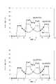
ここで、封止部材22aと封止部材22bの開封開始時間が同時であった場合のそれぞれのトルクと合計トルクの推移を図8に示す。また、封止部材22aと封止部材22bの開封開始時間の差ΔTを、開封部材Bのトルクが極小となる(W+0.5X)/Vとした際のそれぞれのトルクと合計トルクの推移を図9に示す。図に示すように、トルクのピークが一致していた際と比較して、効果的に合計トルクのピークを低減することができている。すなわち、第1の開封方向と第2の開封方向の開封に時間差を設けることで、それぞれの開封トルクの合計のピークを低減することができる。 Here, transition of each torque and total torque when the opening start times of the sealing
以上のように、それぞれの開口部21a,21bは周囲を封止部材22a,22bにより接着されて封止されている。そして、開封部材23の回転により複数の開口部21a,21bを開封する。このときに、第1の開口部21aにおける封止部材22aの開封方向と交差する方向の接着部の引き剥がしと、第2の開口部21bにおける封止部材22bの開封方向と交差する方向の接着部の引き剥がしがずれて行われるように構成する。これにより、複数の封止部材22a,22bを引き剥がす際にも、合計トルクの増大を抑えることができる。同時に、大きく時間をかけることなくすべての封止部材22a,22bを開封することができる。 As described above, the
〔第3実施形態〕
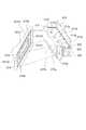
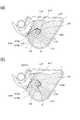
次に第3実施形態に係る現像剤収納ユニットを備えた現像装置について説明する。図10は本実施形態に係る現像剤収納ユニットの斜視図であり、図11は現像剤収納ユニットを備えた現像装置の断面図である。また、図12は図11の矢印G方向から見た図であり、図13は開封を開始した直後の断面図である。[Third Embodiment]
Next, a developing device including the developer storage unit according to the third embodiment will be described. FIG. 10 is a perspective view of the developer storage unit according to the present embodiment, and FIG. 11 is a cross-sectional view of a developing device including the developer storage unit. 12 is a view seen from the direction of arrow G in FIG. 11, and FIG. 13 is a cross-sectional view immediately after the opening is started.
本実施形態に係る現像装置は、図11に示すように、第1の枠体117と第2の枠体118を有する。そして、第1の枠体117は、現像手段である現像ローラ113と現像ブレード115を有し、第2の枠体118は現像剤であるトナーを内包する可撓性容器でできた現像剤収納部116を有する。 The developing device according to the present embodiment includes a
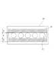
図10及び図11に示すように、可撓性容器で構成したトナーを収納する現像剤収納部116は、第2の枠体118との第1の固定部116aと第2の固定部116bを有し、内部のトナーを排出する開口部116cを有している。本実施形態の開口部116cは、図12に示すように、四角形の大きな1つの開口部により構成されている。現像剤収納後に前記開口部116cを封止部材119で覆うとともに、周囲を接着することで封止している。そして、前記封止部材119は前記接着部で折り返されて端部が開封部材120に係止されている。そして、前記開口部116cは現像剤収納部116に対して、開封部材120の回転軸からの最近接点に位置するように形成される。なお、本実施形態では開口部116cの略中央に開封部材120の回動中心が位置するように配置されている。 As shown in FIGS. 10 and 11, the
封止部材119による封止部は、図12に示すように開封の進行方向Eに対して略垂直な方向Fに第1の封止部119fと第2の封止部119gが形成され、開封方向と並行な方向Eに対して第3の封止部119hを有して途切れない閉じた封止部をなしている。そして、現像剤収納部116には前記第1の封止部119fと接合する第1の接合部116d、前記第2の封止部119gと接合する第2の接合部116e、第3の封止部119hと接合する第3の接合部116fが形成されている。これら封止部と接合部とが例えば封止部の一部が溶けた溶着、あるいは接着剤による接着等することにより開口部が密封される。そして、開封する場合の開封進行方向E(第1の開封方向及び第2の開封方向)は、開口部116cが設けられた面と平行に進行する。このため、開封部材120が回転して封止部材119が剥離されるとき、図13に示すように、現像剤収納部116の前記第1の接合部116dと、第2の接合部116eから封止部材119が剥離されて開封が開始される。すなわち、開封に際しては前記第1の接合部116dが第1の開封開始位置となり、前記第2の接合部116eが第2の開封開始位置となる。 As shown in FIG. 12, the sealing
封止部材119は、図11に示すように、開口部116cを覆う封止部119aと、開封部材120に係止固定される第1の固定部(取り付け部)119dと第2の固定部(取り付け部)119eとを有する。さらに封止部材119は、封止部119aと第1の固定部119dとを連結する連結部(第1の連結部)119bと、封止部119aと第2の固定部119eとを連結する連結部(第2の連結部)119cを有している。 As shown in FIG. 11, the sealing
トナーが収納され、開口部116cを封止部材119により封止された現像剤収納部116は第1の固定部116a及び第2の固定部116bにおいて第2の枠体118に係止等によって固定される。そして、第1の枠体117と第2の枠体118とを結合することにより現像剤収納ユニットが形成される。また、開封部材120は装置本体に回転可能に設けられている。 The
前述の構成により開封を実現するためには必ず第1の封止部119fと第2の封止部119gが最初に引き剥がされる必要がある。すなわち、開封部材の回転に伴って、第1の連結部119bの引っ張りにより第1の封止部119fを第1の接合部116dから引き剥がし、第2の連結部119cの引っ張りにより第2の封止部119gを第2の接合部116eから引き剥がす必要がある。従って、現像剤収納部116における全ての貼り合わせ部位において、封止部材119と現像剤収納部116の貼り合わせ部の強度、つまり剥離力が最も弱いことが必須である。他の部位に対しても同様のことが言える。封止部材119と開封部材120の固定力、現像剤収納部116と第2の枠体118との固定力等、に対して前記剥離力が最も弱いことが必須である。 In order to realize opening with the above-described configuration, the
一方で、現像剤収納ユニットはその機能上トナーを内包するため、封止性の観点からは前記剥離力ができるだけ大きい方が有利である。前記剥離力が大きければ、予期せぬ力(例えば、落下時の衝撃力)がかかった場合において意図した状態(画像形成装置内にセットされた状態)以外で開封してしまう事態を回避できる可能性が高いからである。以上のことから、前記剥離力は所望の値になるように制御して設定する必要がある。 On the other hand, since the developer storage unit contains toner in terms of its function, it is advantageous that the peeling force is as large as possible from the viewpoint of sealing performance. If the peeling force is large, it is possible to avoid a situation in which an unexpected force (for example, an impact force at the time of dropping) is applied and the bag is opened except for an intended state (a state set in the image forming apparatus). It is because the nature is high. From the above, it is necessary to control and set the peeling force so as to have a desired value.
次に、前記剥離力を所望の値にする制御方法について説明をする。本実施の形態では前記剥離力を所望の値(ここでは、トナー封止性を保てる範囲内でできるだけ小さい力)にするために、主に2つの方法をとっている。 Next, a control method for setting the peeling force to a desired value will be described. In the present embodiment, two methods are mainly used in order to set the peeling force to a desired value (here, a force as small as possible within a range in which the toner sealing property can be maintained).
1つ目は、封止部材119にイージーピール性(JIS−Z0238の密封軟包装袋の試験において剥離強さが3N/15mm程度)を発揮する特殊シーラント層を持つラミネート材を適用している。そして袋部材には前記特殊シーラント層と溶着可能で可とう性のあるシート材質(例えば、ポリエチレンやポリプロピレン)を適用することで該剥離部においてイージーピール性を発揮する方法である。特殊シーラント層の処方及び貼り合わせる材質の組み合わせを変えることにより剥離力を低減させることが可能である。 First, a laminate material having a special sealant layer that exhibits easy peel properties (peeling strength is about 3 N / 15 mm in the sealed soft packaging bag test of JIS-Z0238) is applied to the sealing
2つ目は、図11、図13に示すように現像剤収納部116の開口部16cを開封が進む方向(図中矢印E)に対して折り返された状態にする方法である。そして、前記第1の開封開始位置である第1の接合部116dが第1の固定部116aと開封部材120の間に配置され、前記第2の開封開始位置である第2の接合部116eが第2の固定部116bと開封部材120の間に位置するように配置されている。すなわち、図11に示すように、第1の接合部116dと第2の接合部116eとを重力方向上に配置した場合、開封部材120は前記重力方向において第1の接合部116dと第2の接合部116eとの間に配置されている。 The second method is a method in which the opening 16c of the
これにより、開封部材120が図11の矢印Cの方向に回転すると封止部材119が矢印Dの方向に引っ張られる。ここで、現像剤収納部116は第1の固定部116aと第2の固定部116bにより枠体に固定されている。このため、第1の接合部116dと第2の接合部116eの部分に矢印Hの方向に力がかかり、封止部119gと119gの開封が始まる。このとき現像剤収納部116と封止部材119は図11に示すような折り返し部の角度が90度以下となり、傾斜剥離の位置関係になる。このように、開封が進む方向(図中矢印E)に対して折り返された状態にすることで前記剥離力を低減することができる。 Thus, when the opening
特に開封末期の剥離状態が、図14に示すように、封止部材119の第1の連結部119bと封止部がなす角θ1と封止部材119の第2の連結部119cと封止部がなす角θ2の両方が90度以下の位置関係が保てるため、開封に至るまで剥離力を低減できる。 In particular, as shown in FIG. 14, the peeled state at the end of opening is the angle θ <b> 1 formed by the first connecting
なお、開封部材120は断面四角形状の軸で、一面に撹拌部材121が固定され、現像剤収納部116から排出されたトナーの撹拌に加え、現像ローラ113側への搬送手段を兼ねている。そして、開封後更に開封部材120の回転が進むと、封止部材119は撹拌部材121と共に回転する。封止部材119は撹拌部材121に巻きつくには至らない長さに設定され、撹拌部材121のトナーを撹拌する機能は確保される。ここで撹拌部材121は弾性を有しており、回転時に現像剤収納部116の開口部116cよりも小さくなる設定のため、現像剤収納部116に収納されたトナーを押す。そのため撹拌部材121により現像剤収納部116の内部のトナーが押し出されて開口部116cより排出される。 The unsealing
以上のように、本実施例では開封部材120を回転するだけで、大きな開口部に対応する封止部材119の開封が可能となり、現像剤収納部116の確実で安定的な開封とトナー排出が可能となる。また、開口部116cにおける短手方向に引くことで開封が可能であるため、剥離距離を大幅に短縮することができ、トナー供給までのリードタイムを短縮することが可能になる。 As described above, in this embodiment, it is possible to open the sealing
また、開封後の封止部材119が開封部材120に固定されていることで、プロセスカートリッジから廃材を出すことなく開封ができる。さらに撹拌部材121により現像剤収納部116の内部からのトナーの排出も確実に行われる。 Moreover, since the sealing
さらに封止部材119が開封部材120と共に運動することが可能であるため、プロセスカートリッジ内においてトナーの撹拌効果が期待できる。さらに、現像剤収納部116が可撓性容器の形態をとることにより、トナーをユニットとして扱えるため、トナー充填工程をプロセスカートリッジの組立工程から分離でき、清浄環境が必要である組立工程でのトナー飛散を少なくすることができる。 Further, since the sealing
なお、開封部材120は回転により封止部材119を巻き取る構成がスペースを取らずに望ましいが、開封部材120を開口部116cから離れる方向に移動させることで開封することも可能である。 In addition, although the structure which winds up the sealing
〔第4実施形態〕
次に第4実施形態に係る現像剤収納ユニットについて説明する。図15は本実施形態に係る現像剤収納ユニットを備えたプロセスカートリッジの断面図である。[Fourth Embodiment]
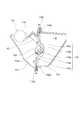
Next, a developer storage unit according to the fourth embodiment will be described. FIG. 15 is a cross-sectional view of a process cartridge including a developer storage unit according to this embodiment.
本実施形態のプロセスカートリッジは感光体ドラム202、帯電ローラ203、及びクリーニング部材231を備えた感光体ユニット230、及び、現像ローラ222を有する現像ユニット220に分かれている。現像ユニット220は現像装置を構成するものであり、トナーを収納する現像剤収納ユニットと、現像ローラ222や現像ブレード223が設けられた現像室とが一体的に構成されている。上記現像ユニット220及び感光体ユニット230からなるプロセスカートリッジを用いて画像形成する画像形成プロセスは前述した実施形態と同様である。 The process cartridge of this embodiment is divided into a
<現像剤収納ユニット>
ここで、本実施形態に係る現像剤収納ユニットについて説明する。図16は本実施形態に係る現像剤収納ユニットの断面模式図であり、図17は開封部材と封止部材とトナー供給開口部の関係を説明した模式斜視図である。<Developer storage unit>
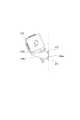
Here, the developer storage unit according to the present embodiment will be described. FIG. 16 is a schematic cross-sectional view of the developer storage unit according to this embodiment, and FIG. 17 is a schematic perspective view illustrating the relationship among the opening member, the sealing member, and the toner supply opening.
図16に示すように、現像枠体221により現像剤収納部221aが一体的に形成されている。そして、現像剤収納部221aには、トナーt、現像剤収納部221aと現像室224aとに隔てる隔壁部221bが設けられている。さらに現像剤収納部221aには、現像剤収納部221aと現像室224aとを連通するトナー供給用の開口部221c、開封部材226、開口部221cを開封可能に封止するための封止部材217、撹拌部材218が設けられている。 As shown in FIG. 16, the
開口部221cは、図17に示すように、現像ユニット220の長手方向と略平行な辺221c1、辺221c2と、略垂直な辺221c3、辺221c4により四角形状を形成している。但し、開口部221cは四角形状に限定されるものではなく、楕円形状や多角形形状等でも良い。 As shown in FIG. 17, the
ここで、図17に示すように、撹拌部材218は、PET、PC、PP等の可撓性材料を用いて形成され、開封部材226に固定されている。撹拌部材218と開封部材226の固定は、溶剤や接着剤、両面テープを用いた接着、レーザー溶着や熱溶着、超音波溶着等で行われる。また、撹拌部材218は開封部材226と一体で形成されてもよい。 Here, as shown in FIG. 17, the stirring
(開口部の封止)
封止部材217は、凝集剥離を可能とするイージーピールフィルムによって形成されていて、封止部217a、第1の固定部217b、第2の固定部217dを有する。(Sealing the opening)
The sealing
また、封止部217aは、開口部221cの周縁全周を囲うように、隔壁部221bに設けられた貼付部221b1の接合部215に開封可能に取り付けられる。ここで、接合部215は、溶剤や接着剤を用いた接着の他、レーザー溶着や熱溶着、超音波溶着によって形成される。ここで、接合部215は、第1の接合部215a、第2の接合部215bを有する。また、封止部217aは、第1の接合部215aに接合され第1の開封位置である第1の開封開始部217e、第2の接合部215bに接合され第2の開封位置である第2の開封開始部217fを有する。 Moreover, the sealing
そして、封止部材217は、第1の固定部217b、第2の固定部217dにおいて開封部材226に固定されている。ここで、第1の固定部217b、第2の固定部217dと開封部材226の固定は、両面テープ52、両面テープ53、または熱溶着、カシメ、接着等で固定される。 The sealing
(封止部材の長さ)
次に、封止部材217の断面方向長さの関係を説明する。(Length of sealing member)
Next, the relationship between the lengths in the cross-sectional direction of the sealing
図16に示すように、第1の開封開始部217eから第2の開封開始部217fの封止部材217長さをL5、第1の開封開始部217eに力S1がかかる時の第2の開封開始部217fから開封部材226までの封止部材217の長さをL6とする。また、第2の開封開始部217fに力S2がかかる時の第2の開封開始部217fから開封部材226までの長さをL7とする。 As shown in FIG. 16, the length of the sealing
ここで、第1の開封開始部217eより封止部材217が剥がされている間に第2の開封開始部217fからも剥がされ始め、又は第1の開封開始部217eと第2の開封開始部217fが同時に剥がされるためには、L5>L6−L7>=0という関係となる。 Here, while the sealing
(開封部材の配置)
次に、開封部材226の配置について説明する。図16に示すように、第1の開封開始部217eから第2の開封開始部217fへの方向を矢印Q1方向とし、矢印Q1方向とは逆の方向を矢印Q2方向とする。また、開封時に第1の開封開始部217eにかかる力S1と矢印Q1方向で作られる角度を第1の剥離角度θ1、開封時に第2の開封開始部217fにかかる力S2と矢印Q2方向で作られる角度を第2の剥離角度θ2とする。ここで、封止部材217を第1の開封開始部217eと第2の開封開始部217fから傾斜剥離するため、開封部材226は第1の剥離角度θ1、第2の剥離角度θ2がそれぞれ90度以下になる位置に配置されている。(Arrangement of opening member)
Next, the arrangement of the opening
すなわち、開封部材226は、開封部材226の回転による開封時において、以下のように配置されている。すなわち、第1の開封開始部217eを通り、開封部材226の外接円であって開封部材226の回転方向下流側に接する線と、第1の開封開始部217eと第2の開封開始部217fとを結ぶ線とのなす角度が90度以下になる位置に配置されている。なお、第1開封部217eを通って開封部材226の外接円Cに接する線は、図21に示すように、線aと線bがある。線aは開封部材226の回転方向上流側に接する線であり、線bは開封部材226の回転方向下流側に接する線である。したがって、前述した第1の開封開始部217eを通り、開封部材226の外接円であって開封部材226の回転方向下流側に接する線とは、この場合、線bを意味する。 That is, the opening
さらに、開封部材226は、第2の開封開始部217fを通り開封部材226の外接円であって開封部材の回転方向下流側に接する線と、第2の開封開始部217fと第1の開封開始部217eとを結ぶ線とのなす角度が90度以下となるように配置されている。 Further, the unsealing
つまり、封止部217aに垂直で第1の開封開始部217eを通る線を線L1、封止部217aに垂直で第2の開封開始部217fを通る線を線L2とする。このとき、第1の剥離角度θ1、第2の剥離角度θ2がそれぞれ90度以下になるために、開封部材226は線L1と線L2の間に配置されている。 That is, a line perpendicular to the sealing
(現像剤収納ユニットの組立方法)
次に現像剤収納部ユニットの組立方法について図18を用いて説明する。図18(a)に示すように、両面テープ252で開封部材226に第2の固定部217dが固定された封止部材217が矢印P1方向に、現像枠体224の貼付部221b1に熱溶着又は超音波溶着で固定される。(Assembling method of developer storage unit)
Next, a method for assembling the developer storage unit will be described with reference to FIG. As shown in FIG. 18A, the sealing
この際、封止部材217は開口部221cの周縁に連続に溶着されて、接合部215が作られる(図17のハッチング部参照)。 At this time, the sealing
次に、図18(b)に示すように、開封部材226を矢印P2方向に動かし、開封部材226が現像枠体224に設けられた穴部221dに嵌入され、回転可能に支持される。 Next, as shown in FIG. 18B, the opening
そして、図18(c)に示すように、封止部材217の第1の固定部217bは矢印P3方向に動かされ、第1の固定部217bは開封部材226の両面テープ253に固定される。これによって、封止部材217は、開封部材226に対し、第1の固定部217bと第2の固定部217dの二つの固定部を持つ。 18C, the
さらに、図18(d)に示すように、受台255に置かれた現像枠体224と矢印P4方向に溶着ホーンにより力を受けたトナー容器蓋229が超音波溶着で溶着される。 Further, as shown in FIG. 18 (d), the developing
ここで、現像枠体224とトナー容器蓋29を超音波溶着で溶着することにより現像剤収納部が形成されたときには、現像枠体224の面とトナー容器蓋229の面が接合する。 Here, when the developer accommodating portion is formed by welding the developing
その後、トナーtを現像剤収納部221aにトナー穴部224cより充填し、トナー穴部224cをトナーキャップ(不図示)やシール等で封止する。ここで、トナーtは、現像枠体224とトナー容器蓋229を超音波溶着する前に、現像枠体224の開口部221cより充填してもよい。 Thereafter, the toner t is filled in the
(封止部材の開封方法)
次に、封止部材217の開封方法について、図16を用いて説明する。プロセスカートリッジが画像形成装置に装着された時には、画像形成装置に設けられた駆動手段(不図示)によりプロセスカートリッジに駆動力が伝達され、図16(a)に示すように、開封部材226は矢印E方向に回転する。開封部材226が回転すると、開封部材226は封止部材217を巻き始める。(Opening method of sealing member)
Next, a method for opening the sealing
さらに、図16(a)に示すように、開封部材226の回転によって開封部材226が封止部材217を巻き始めていくと、第1の開封開始部217eにおいて力S1が加わり、封止部材217は力S1方向に引かれる。ここで、前述の通り、力S1と、矢印Q1方向との角度を第1の剥離角度θ1とすると、第1の剥離角度θ1は90度以下になっている。このとき、封止部材217が隔壁部221bより剥離され、第1の開封開始部217eから矢印Q1方向に、開口部221cが露出する。 Further, as shown in FIG. 16A, when the opening
ここで、図16(b)に示すように、開封部材226の回転により封止部材217が矢印Q1方向に開封されている間に、第2の開封開始部217fにおいて力S2が加わり、封止部材217は力S2方向に引かれる。ここで、前述の通り、力S2と、矢印Q2方向との角度を第2の剥離角度θ2とすると、第2の剥離角度θ2は90度以下になっている。そして、封止部材217が隔壁部221bから剥離され、第2の開封開始部217fから矢印Q2方向に、開口部221cが露出する。 Here, as shown in FIG. 16B, while the sealing
次に、図16(c)に示すように、さらに開封部材226の回転が進むと、開封部材226によって封止部材217は巻き取られ、開口部221cが完全に露出する。 Next, as shown in FIG. 16C, when the rotation of the opening
(比較例)
ここで、比較例として図19を用い、封止部材の開封開始位置が1つである場合について説明する。(Comparative example)
Here, the case where the opening start position of the sealing member is one will be described using FIG. 19 as a comparative example.
図19に示す現像剤収納ユニットは、封止部材417を第1の接合部415aから第2の接合部415bへ向けて剥離するものである。ここで、図19(a)に示すように、開封部材426の回転軸Z4を中心として、開封部材426の最外形を通る外接円を円X4とする。また、第1の接合部415aから回転軸Z4に引いた線と円X4が交わる点を点Jとする。そして、第1の接合部415aを通り、点Jに対して開封部材426の回転方向下流側の円X4への接線を第1の線L10とする。また、第1の接合部415aと第2の接合部415bとを結んだ線を第2の線L11とする。また、第1の線L10と第2の線L11が成す角をα4とする。α4は第1の接合部415aの貼付部421bにおける封止部材417の剥離角度を表わしている。 In the developer storage unit shown in FIG. 19, the sealing
また、図19(b)に示すように、第2の接合部415bを通り、開封部材426の回転方向下流側の円X4への接線を第4の線L10aとする。そして、第2の線L11と第4の線L10aの成す角をα4aとする。α4aは第2の接合部における貼付部421b1における封止部材417の剥離角度を表わしている。 Further, as shown in FIG. 19B, a tangent to the circle X4 passing through the second joint 415b and downstream of the opening
ここで、第2の線L11に垂直で第1の接合部415aを通る線を第3の線L13、第2の線L11に垂直で第2の接合部415aを通る線を第4の線L14とし、第3の線L13と第4の線L14の間にできる範囲を範囲Gとする。また、開封部材426が回転軸Z4中心に矢印H方向に回転することで封止部材417を巻き取る。 Here, a line perpendicular to the second line L11 and passing through the first joint 415a is a third line L13, and a line perpendicular to the second line L11 and passing through the second joint 415a is a fourth line L14. A range formed between the third line L13 and the fourth line L14 is a range G. Further, the opening
つまり、α4、α4aが90度以下になるように開封部材426を配置するためには、第4の線L14の線上、第3の線L13の線上、または範囲Gよりも外側から、封止部材417に引き剥がし力が作用するように、開封部材426が配置される。その結果、第1の接合部415aは第3の線L13より第4の線L14側から引き剥がされ、第2の接合部415aは第4の線L14より第3の線L13と逆側から引き剥がされる。 In other words, in order to arrange the opening
このため、トナー収納部421aを小型に設計するとき、トナー収納部421aは少なくとも範囲Gよりも大きくなってしまう。 For this reason, when the toner storage portion 421a is designed to be small, the toner storage portion 421a is at least larger than the range G.
これに対して、前述した本実施形態にあっては、開口部221cを封止する封止部材217は開封部材226に対し第1の固定部217bと第2の固定部217dの二つの固定部を持つ。さらに、接合部215の開封開始位置を複数設けることで、開口部221cに垂直な線と接合部215とで作られる範囲内に開封部材226が配置されても、封止部材217の傾斜剥離が可能となる。 On the other hand, in the above-described embodiment, the sealing
よって、封止部材217の傾斜剥離を可能としつつ、図16に示すように封止部217aに垂直で第1の開封開始部217eを通る線を線L1と、封止部217aに垂直で第2の開封開始部217fを通る線を線L2の間に開封部材426の外接円を配置できる。それによって、カートリッジの小型化が可能になる。 Therefore, while allowing the sealing
さらに、開封開始位置を複数設け、一方の開封開始位置より封止部材217が剥がされている間に他方からも剥がされ始める、または複数の開封開始位置より同時に剥がされるため、開封開始位置が一つの現像剤収納容器又は現像装置に比べ、開封時間が短い。このようにして、開封時間が短くなることで、トナーを現像室へ早く供給でき、1枚目のプリント時間が短くなる。 Further, a plurality of opening start positions are provided, and since the sealing
なお、現像剤収納部内に、開封部材226及び封止部材217を配置する構成にあっては、図17に示すようにするとよい。すなわち、封止部材217の開封部材取り付け部である第1の固定部217bと第2の固定部217dから封止部217aまでの連結部に複数の穴217gを設けるようにするとよい。このようにすると、図16に示すように、現像剤収納部内で開封部材217を回転して封止部材217を巻き取るときに、穴217gから現像剤が逃げるようになるため、巻き取りトルクの増大を抑制することが可能となる。 In the configuration in which the
(開封部材が現像剤収納部の外にある例)
図16に示した実施形態では開封部材226が現像剤収納部221aの内部に設けた例を示した。しかし、図20に示すように、開封部材226は現像剤収納部221aの外部に配置してもよい。この場合でも、開封開始位置を二カ所設け、封止部217aに垂直で第1の開封開始部217eを通る線L1と、封止部217aに垂直で第2の開封開始部217fを通る線L2の間に開封部材226の外接円が入るように配置しても同様の効果が得られる。(Example in which the opening member is outside the developer container)
In the embodiment shown in FIG. 16, an example in which the
4 …現像装置
19d 、116a、217b …第1の固定部
19e 、116b、217d …第2の固定部
20、116、221a …現像剤収納部
21、21a、21b、116c …開口部
22、22a、22b、119、217、417 …封止部材
23、120、226、426 …開封部材
24 …現像ローラ
27、221、224 …枠体
116d、215a、415a …第1の接合部
116e、215b、415b …第2の接合部
116f …第3の接合部
119a …封止部
121 …撹拌部材
215 …接合部
217a …封止部4...
Claims (19)
Translated fromJapanese開口を有し、かつ現像剤を収納する収納部であって、枠体に収納された可撓性容器で構成された収納部と、
前記開口を封止する封止部材と、
前記封止部材を巻き取るために回転可能な開封部材と、を有し、
前記封止部材を前記収納部から引き剥がし前記開口を開封する開封方向は、2方向あり、
前記2方向は、開封が進行する第1の開封方向と、前記第1の開封方向とは逆側に開封が進行する第2の開封方向とを有することを特徴とする現像剤収納ユニット。A developer storage unit for storing the developer,
A storage portion having an opening and storing a developer, the storage portionbeing formed of a flexible container stored in a frame;
A sealing member for sealing the opening;
An opening member rotatable to wind up the sealing member,
There are two opening directions for peeling off the sealing member from the storage portion and opening the opening,
The developer storage unit characterized in that the two directions have a first opening direction in which the opening proceeds and a second opening direction in which the opening proceeds on the opposite side to the first opening direction.
開口を有し、かつ現像剤を収納する収納部と、
前記開口を封止する封止部材と、
前記封止部材を巻き取るために回転可能であって、前記収納部内に設けられた開封部材と、を有し、
前記封止部材を前記収納部から引き剥がし前記開口を開封する開封方向は、2方向あり、
前記2方向は、開封が進行する第1の開封方向と、前記第1の開封方向とは逆側に開封が進行する第2の開封方向とを有することを特徴とする現像剤収納ユニット。A developer storage unit for storing the developer,
A storage section having an opening and storing a developer;
A sealing member for sealing the opening;
An opening memberthat is rotatable to wind up the sealing member andis provided in the storage unit ;
There are two opening directions for peeling off the sealing member from the storage portion and opening the opening,
The developer storage unit characterized in that the two directions have a first opening direction in which the opening proceeds and a second opening direction in which the opening proceeds on the opposite side to the first opening direction.
前記開封部材は、前記第1の開封開始位置を通り前記開封部材の外接円と接する接線のうち前記開封部材の回転方向の下流側に接する接線と、前記第1の開封開始位置と前記第2の開封開始位置とを結ぶ線と、のなす角度が90度以下となるように、配置されていることを特徴とする請求項1から4のいずれか1項に記載の現像剤収納ユニット。The storage unit has a first opening start position and a second opening start position at which exposure of the opening is started,
The opening member includes a tangent line that contacts a downstream side of the rotation direction of the opening member among a tangent line that passes through the first opening start position and contacts a circumscribed circle of the opening member, the first opening start position, and the second opening position. of the line connecting the open trigger position, so as to form an angle of equal to or less than 90 degrees, the developer accommodating unit according to claim 1, any one of4, characterized in that it is arranged.
前記開封部材は、前記第2の開封開始位置を通り前記開封部材の外接円と接する接線のうち前記開封部材の回転方向の下流側に接する接線と、前記第1の開封開始位置と前記第2の開封開始位置とを結ぶ線と、のなす角度が90度以下となるように、配置されていることを特徴とする請求項1から5のいずれか1項に記載の現像剤収納ユニット。The storage unit has a first opening start position and a second opening start position at which exposure of the opening is started,
The opening member includes a tangent line that touches a downstream side in a rotation direction of the opening member among a tangent line that passes through the second opening start position and contacts a circumscribed circle of the opening member, the first opening start position, and the second opening position. a line connecting the opening start position of, as the angle of equal to or less than 90 degrees, the developer accommodating unit according to claim 1, any one of5, characterized in that it is arranged.
前記第1の開封方向と前記第2の開封方向とは、前記開口を有する前記面と平行であることを特徴とする請求項1から8のいずれか1項に記載の現像剤収納ユニットThe storage portion has a surface having the opening,
Wherein the first unsealing direction and the second unsealing direction, the developer accommodating unit according to any one of claims 18, characterized in that parallel to the surface having the opening
前記開封部材の回転により、前記封止部材は前記最近接点から遠い側から前記最近接点に向けて開封されることを特徴とする請求項11記載の現像剤収納ユニット。The opening is provided at least one on each of the upstream side and the downstream side in the rotation direction of the opening member with respect to the storage portion with respect to the closest point from the rotation shaft of the opening member.
12. The developer storage unit according to claim11 , wherein the sealing member is opened toward the nearest contact point from a side far from the nearest contact point by rotation of the opening member.
前記第1の封止部材と前記第2の封止部材とは、それぞれ異なる開口を封止することを特徴とする請求項11又は12記載の現像剤収納ユニット。The sealing member has a first sealing member and a second sealing member,
Wherein the first sealing member and the second sealing member, the developer accommodating unit according to claim11 or12 wherein sealing the different apertures, respectively.
前記現像剤収納ユニットから供給される現像剤を担持する現像剤担持体と、を有することを特徴とする現像装置。The developer storage unit according to any one of claims 1 to16 ,
And a developer carrying member for carrying the developer supplied from the developer storage unit.
像担持体を有することを特徴とするプロセスカートリッジ。A process cartridge comprising the developer storage unit according to any one of claims 1 to16 and any one of the developing devices according to claim17 , and having an image carrier.
Priority Applications (3)
| Application Number | Priority Date | Filing Date | Title |
|---|---|---|---|
| JP2014056386AJP6282149B2 (en) | 2013-06-05 | 2014-03-19 | Developer storage unit, developing device, process cartridge, and image forming apparatus |
| US14/293,450US9207581B2 (en) | 2013-06-05 | 2014-06-02 | Developer accommodating unit, developing device, process cartridge and image forming apparatus |
| CN201410244980.XACN104238308B (en) | 2013-06-05 | 2014-06-05 | Developer-containing unit, developing apparatus, handle box and imaging device |
Applications Claiming Priority (3)
| Application Number | Priority Date | Filing Date | Title |
|---|---|---|---|
| JP2013118885 | 2013-06-05 | ||
| JP2013118885 | 2013-06-05 | ||
| JP2014056386AJP6282149B2 (en) | 2013-06-05 | 2014-03-19 | Developer storage unit, developing device, process cartridge, and image forming apparatus |
Publications (2)
| Publication Number | Publication Date |
|---|---|
| JP2015014779A JP2015014779A (en) | 2015-01-22 |
| JP6282149B2true JP6282149B2 (en) | 2018-02-21 |
Family
ID=52005587
Family Applications (1)
| Application Number | Title | Priority Date | Filing Date |
|---|---|---|---|
| JP2014056386AExpired - Fee RelatedJP6282149B2 (en) | 2013-06-05 | 2014-03-19 | Developer storage unit, developing device, process cartridge, and image forming apparatus |
Country Status (3)
| Country | Link |
|---|---|
| US (1) | US9207581B2 (en) |
| JP (1) | JP6282149B2 (en) |
| CN (1) | CN104238308B (en) |
Families Citing this family (32)
| Publication number | Priority date | Publication date | Assignee | Title |
|---|---|---|---|---|
| JP6066841B2 (en) | 2012-09-10 | 2017-01-25 | キヤノン株式会社 | Developing cartridge, process cartridge, and image forming apparatus |
| JP6120730B2 (en) | 2012-09-13 | 2017-04-26 | キヤノン株式会社 | Developer storage unit, process cartridge, image forming apparatus |
| JP6173069B2 (en) | 2013-06-27 | 2017-08-02 | キヤノン株式会社 | Developer container, developer cartridge, process cartridge, and image forming apparatus |
| JP2015092226A (en) | 2013-10-01 | 2015-05-14 | キヤノン株式会社 | Powder conveyance mechanism, powder conveying method, developer storage container, cartridge, and image forming apparatus |
| JP6381222B2 (en) | 2014-02-18 | 2018-08-29 | キヤノン株式会社 | Developer storage unit and manufacturing method thereof, developing device, process cartridge, and image forming apparatus |
| JP6138181B2 (en) | 2014-04-15 | 2017-05-31 | キヤノン株式会社 | Resin molded product and cartridge used for image forming apparatus, method for manufacturing movable member used for image forming apparatus, and method for manufacturing cartridge |
| EP2977820B1 (en) | 2014-07-25 | 2021-02-17 | Canon Kabushiki Kaisha | Cartridge and image forming apparatus |
| JP6415199B2 (en) | 2014-09-10 | 2018-10-31 | キヤノン株式会社 | Process cartridge |
| EP3226076B1 (en) | 2014-11-28 | 2020-08-05 | Canon Kabushiki Kaisha | Cartridge, member configuring cartridge, and image formation device |
| CN118050966A (en) | 2015-02-27 | 2024-05-17 | 佳能株式会社 | Drum units, cartridges and couplings |
| US9785087B2 (en)* | 2015-03-27 | 2017-10-10 | Canon Kabushiki Kaisha | Developer container, developing apparatus, process cartridge, and image forming apparatus |
| JP6525662B2 (en)* | 2015-03-27 | 2019-06-05 | キヤノン株式会社 | Developer container, developing device, process cartridge, and image forming apparatus |
| JP6529306B2 (en)* | 2015-03-27 | 2019-06-12 | キヤノン株式会社 | Developer container, developing device, process cartridge and image forming apparatus |
| JP6576100B2 (en)* | 2015-05-26 | 2019-09-18 | キヤノン株式会社 | Developer container, developing device, process cartridge, and image forming apparatus |
| JP7013113B2 (en) | 2015-06-30 | 2022-01-31 | キヤノン株式会社 | Sealing members, units and image forming devices |
| JP2017134297A (en)* | 2016-01-29 | 2017-08-03 | キヤノン株式会社 | Developer container, developing device, process cartridge, and image forming apparatus |
| WO2017142099A1 (en) | 2016-02-18 | 2017-08-24 | Canon Kabushiki Kaisha | Cartridge and image forming apparatus |
| JP6753112B2 (en)* | 2016-03-31 | 2020-09-09 | ブラザー工業株式会社 | Developer cartridge and developer storage unit |
| KR102128342B1 (en) | 2016-07-04 | 2020-07-08 | 캐논 가부시끼가이샤 | Reproduction method for developing device |
| RU2019108099A (en) | 2016-08-26 | 2020-09-28 | Кэнон Кабусики Кайся | DRUM ASSEMBLY, CARTRIDGE, ELECTROPHOTOGRAPHIC IMAGER AND COUPLING ELEMENT |
| GB2567401B (en) | 2016-08-26 | 2022-03-09 | Canon Kk | Drum unit, cartridge, electrophotographic image forming apparatus and coupling member |
| JP2019074616A (en)* | 2017-10-16 | 2019-05-16 | キヤノン株式会社 | Developer storage member, developer storage unit, developing device, process cartridge, and image forming apparatus |
| US10739702B2 (en) | 2018-07-06 | 2020-08-11 | Canon Kabushiki Kaisha | Developer accommodating unit, cartridge and image forming apparatus |
| US10747143B2 (en)* | 2018-07-31 | 2020-08-18 | Canon Kabushiki Kaisha | Developer accommodating unit, process cartridge, and image forming apparatus |
| US10642189B2 (en)* | 2018-07-31 | 2020-05-05 | Canon Kabushiki Kaisha | Developer container unit, developing apparatus, and process cartridge |
| US10969730B2 (en) | 2019-02-25 | 2021-04-06 | Canon Kabushiki Kaisha | Image forming apparatus and image forming unit |
| CN119472200A (en) | 2019-06-12 | 2025-02-18 | 佳能株式会社 | Boxes, Accessories and Mounting Kits |
| CN117908343A (en) | 2019-08-09 | 2024-04-19 | 佳能株式会社 | Toner container |
| WO2021054482A1 (en) | 2019-09-17 | 2021-03-25 | キヤノン株式会社 | Developer supply device and image forming apparatus |
| JP2022096094A (en) | 2020-12-17 | 2022-06-29 | キヤノン株式会社 | Developer replenishment device and image forming device |
| JP2023146010A (en)* | 2022-03-29 | 2023-10-12 | 富士フイルムビジネスイノベーション株式会社 | Powder storage container, powder supply device, development device and image formation apparatus |
| US12411449B2 (en) | 2022-06-24 | 2025-09-09 | Canon Kabushiki Kaisha | Process unit including first, second and third conveyance members for conveying developer |
Family Cites Families (61)
| Publication number | Priority date | Publication date | Assignee | Title |
|---|---|---|---|---|
| US4969557A (en)* | 1985-11-26 | 1990-11-13 | Ricoh Co., Ltd. | Toner cartridge |
| JPS6449864U (en)* | 1987-09-17 | 1989-03-28 | ||
| JPH03221981A (en)* | 1990-01-29 | 1991-09-30 | Ricoh Co Ltd | Developing device |
| JPH0466980A (en) | 1990-07-04 | 1992-03-03 | Canon Inc | developer supply device |
| US5142335A (en)* | 1990-11-26 | 1992-08-25 | Mita Industrial Co., Ltd. | Electrostatic latent image-developing device and toner cartridge used therefor |
| JPH05197288A (en) | 1992-01-20 | 1993-08-06 | Canon Inc | Development device |
| JPH05289502A (en)* | 1992-04-09 | 1993-11-05 | Ricoh Co Ltd | Toner cartridge |
| JP3172070B2 (en)* | 1995-11-29 | 2001-06-04 | 京セラミタ株式会社 | Toner cartridge |
| JPH10222041A (en) | 1996-12-03 | 1998-08-21 | Canon Inc | Process cartridge and electrophotographic image forming apparatus |
| JP3363727B2 (en) | 1996-12-12 | 2003-01-08 | キヤノン株式会社 | Process cartridge, electrophotographic image forming apparatus, process cartridge assembling method, and waste toner container assembling method |
| JPH10228224A (en) | 1997-02-14 | 1998-08-25 | Canon Inc | Process cartridge and electrophotographic image forming apparatus |
| JPH10228223A (en) | 1997-02-14 | 1998-08-25 | Canon Inc | Process cartridge and electrophotographic image forming apparatus |
| JP3745111B2 (en) | 1997-03-18 | 2006-02-15 | キヤノン株式会社 | Coupling member, process cartridge, and process cartridge assembly method |
| JP2000019841A (en) | 1998-07-02 | 2000-01-21 | Canon Inc | Developing device and process cartridge |
| JP2000098729A (en) | 1998-09-22 | 2000-04-07 | Canon Inc | Developing device, process cartridge, electrophotographic image forming device |
| JP2000098855A (en) | 1998-09-24 | 2000-04-07 | Canon Inc | Process cartridge and electrophotographic image forming apparatus |
| JP2000098809A (en) | 1998-09-24 | 2000-04-07 | Canon Inc | Electrophotographic photosensitive drum, process cartridge, and electrophotographic image forming apparatus |
| JP2000131945A (en) | 1998-10-26 | 2000-05-12 | Canon Inc | Developing device and process cartridge |
| JP2001034055A (en)* | 1999-02-18 | 2001-02-09 | Canon Inc | Developer container and cartridge |
| JP3372932B2 (en) | 1999-05-20 | 2003-02-04 | キヤノン株式会社 | Process cartridge and electrophotographic image forming apparatus |
| US6549736B2 (en) | 2000-01-19 | 2003-04-15 | Canon Kabushiki Kaisha | Process cartridge, engaging member therefor and method for mounting developing roller and magnet |
| JP3432208B2 (en) | 2000-11-17 | 2003-08-04 | キヤノン株式会社 | Process cartridge, electrophotographic image forming apparatus, and cartridge mounting method |
| JP2002162818A (en)* | 2000-11-27 | 2002-06-07 | Canon Inc | Toner supply container, process cartridge, and method of manufacturing the same |
| JP3566697B2 (en) | 2001-02-09 | 2004-09-15 | キヤノン株式会社 | Process cartridge, electrophotographic image forming apparatus, and separation mechanism |
| JP3542569B2 (en) | 2001-04-27 | 2004-07-14 | キヤノン株式会社 | Process cartridge remanufacturing method |
| JP3564080B2 (en) | 2001-04-27 | 2004-09-08 | キヤノン株式会社 | Process cartridge remanufacturing method |
| JP3840063B2 (en) | 2001-04-27 | 2006-11-01 | キヤノン株式会社 | Process cartridge |
| JP2003140457A (en) | 2001-11-07 | 2003-05-14 | Canon Inc | Developing device, process cartridge, and image forming device |
| JP3595798B2 (en) | 2002-01-31 | 2004-12-02 | キヤノン株式会社 | Process cartridge and electrophotographic image forming apparatus |
| JP4174380B2 (en) | 2002-07-04 | 2008-10-29 | キヤノン株式会社 | Electrophotographic photosensitive drum and process cartridge |
| JP2004094071A (en)* | 2002-09-03 | 2004-03-25 | Canon Inc | Developer supply container |
| US6978100B2 (en) | 2002-09-30 | 2005-12-20 | Canon Kabushiki Kaisha | Process cartridge, developing cartridge and developing roller |
| JP3542588B2 (en) | 2002-09-30 | 2004-07-14 | キヤノン株式会社 | Developing cartridge, mounting method of one end side cover, mounting method of other end side cover, and electrophotographic image forming apparatus |
| US7103291B2 (en)* | 2004-08-23 | 2006-09-05 | Kabushiki Kaisha Toshiba | Printing device and printing program |
| JP4617122B2 (en) | 2004-09-08 | 2011-01-19 | キヤノン株式会社 | Developer transport member, developing device, and process cartridge |
| JP2006171091A (en)* | 2004-12-13 | 2006-06-29 | Canon Inc | Developing device, process cartridge, and electrophotographic image forming apparatus |
| JP2008134483A (en)* | 2006-11-29 | 2008-06-12 | Kyocera Mita Corp | Toner supply device |
| JP4839337B2 (en) | 2008-05-27 | 2011-12-21 | キヤノン株式会社 | cartridge |
| JP5697420B2 (en) | 2010-01-13 | 2015-04-08 | キヤノン株式会社 | Cartridge and image forming apparatus |
| JP5312559B2 (en) | 2010-12-28 | 2013-10-09 | キヤノン株式会社 | Toner container, developing device, process cartridge, and image forming apparatus |
| JP5968032B2 (en) | 2011-05-25 | 2016-08-10 | キヤノン株式会社 | Developing device, process cartridge, image forming apparatus |
| PH12014500118A1 (en) | 2011-07-14 | 2014-02-17 | Canon Kk | Developer accommodating unit, process cartridge, electrophotographic image forming apparatus |
| JP5420026B2 (en) | 2011-07-14 | 2014-02-19 | キヤノン株式会社 | Developer storage container, developer storage unit, process cartridge, electrophotographic image forming apparatus |
| JP5420025B2 (en) | 2011-07-14 | 2014-02-19 | キヤノン株式会社 | Developer storage unit, process cartridge, electrophotographic image forming apparatus |
| EP2733543B1 (en) | 2011-07-14 | 2020-04-15 | Canon Kabushiki Kaisha | Developer storage container, process cartridge, and electrophotographic image forming device |
| JP5771797B2 (en) | 2011-11-29 | 2015-09-02 | キヤノン株式会社 | Developing device, cartridge, and electrophotographic image forming apparatus |
| JP5911275B2 (en) | 2011-11-29 | 2016-04-27 | キヤノン株式会社 | Developer storage unit, developing device, process cartridge, electrophotographic image forming apparatus |
| JP5808233B2 (en) | 2011-11-29 | 2015-11-10 | キヤノン株式会社 | Developer storage unit, developing device, process cartridge, electrophotographic image forming apparatus |
| JP6053404B2 (en) | 2012-06-15 | 2016-12-27 | キヤノン株式会社 | Developer storage unit, developing device, process cartridge, electrophotographic image forming apparatus |
| JP6157078B2 (en) | 2012-09-04 | 2017-07-05 | キヤノン株式会社 | Developing unit, process cartridge, and image forming apparatus |
| JP5693678B2 (en) | 2012-09-10 | 2015-04-01 | キヤノン株式会社 | Developer storage container, developer storage unit, process cartridge, image forming apparatus |
| JP6116162B2 (en) | 2012-09-10 | 2017-04-19 | キヤノン株式会社 | Developer storage unit, developing device, process cartridge, and image forming apparatus |
| JP5980061B2 (en) | 2012-09-11 | 2016-08-31 | キヤノン株式会社 | Developer container, process cartridge, and image forming apparatus |
| JP2014056045A (en) | 2012-09-11 | 2014-03-27 | Canon Inc | Developer storage unit, process cartridge, and electrophotography image forming device |
| JP2014056025A (en) | 2012-09-11 | 2014-03-27 | Canon Inc | Developer storage container, process cartridge, and image forming apparatus |
| JP6120730B2 (en) | 2012-09-13 | 2017-04-26 | キヤノン株式会社 | Developer storage unit, process cartridge, image forming apparatus |
| JP6245932B2 (en) | 2012-11-06 | 2017-12-13 | キヤノン株式会社 | Cartridge, developing cartridge, process cartridge, and image forming apparatus |
| JP6116254B2 (en) | 2013-01-11 | 2017-04-19 | キヤノン株式会社 | Developer storage unit, developing device, process cartridge, image forming apparatus |
| JP6202820B2 (en) | 2013-01-11 | 2017-09-27 | キヤノン株式会社 | Developer storage unit, developing device, process cartridge, and image forming apparatus |
| JP6116253B2 (en) | 2013-01-11 | 2017-04-19 | キヤノン株式会社 | Developer storage unit, developing device, process cartridge, and image forming apparatus including the same |
| JP6112971B2 (en) | 2013-01-11 | 2017-04-12 | キヤノン株式会社 | Developer container, developing device, process cartridge, electrophotographic image forming apparatus |
- 2014
- 2014-03-19JPJP2014056386Apatent/JP6282149B2/ennot_activeExpired - Fee Related
- 2014-06-02USUS14/293,450patent/US9207581B2/ennot_activeExpired - Fee Related
- 2014-06-05CNCN201410244980.XApatent/CN104238308B/ennot_activeExpired - Fee Related
Also Published As
| Publication number | Publication date |
|---|---|
| US20140363196A1 (en) | 2014-12-11 |
| CN104238308B (en) | 2018-12-11 |
| US9207581B2 (en) | 2015-12-08 |
| CN104238308A (en) | 2014-12-24 |
| JP2015014779A (en) | 2015-01-22 |
Similar Documents
| Publication | Publication Date | Title |
|---|---|---|
| JP6282149B2 (en) | Developer storage unit, developing device, process cartridge, and image forming apparatus | |
| US8867955B2 (en) | Developer accommodating unit, process cartridge and electrophotographic image forming apparatus | |
| US9285707B2 (en) | Developer accommodating unit with a urging member for urging a flexible member | |
| JP6116254B2 (en) | Developer storage unit, developing device, process cartridge, image forming apparatus | |
| JP5675888B2 (en) | Developer storage unit, developing device, process cartridge, image forming apparatus | |
| US9529304B2 (en) | Developer accommodating unit, process cartridge, and electrophotographic image forming apparatus | |
| JP5420026B2 (en) | Developer storage container, developer storage unit, process cartridge, electrophotographic image forming apparatus | |
| JP6202820B2 (en) | Developer storage unit, developing device, process cartridge, and image forming apparatus | |
| JP6112971B2 (en) | Developer container, developing device, process cartridge, electrophotographic image forming apparatus | |
| US9213263B2 (en) | Flexible developer accommodating container with unsealable openings | |
| US8958726B2 (en) | Developer accommodating container, process cartridge and electrophotographic image forming apparatus | |
| JP2014056024A (en) | Developer storage container, process cartridge, and image forming apparatus | |
| JP2014056045A (en) | Developer storage unit, process cartridge, and electrophotography image forming device | |
| JP5959936B2 (en) | Developer storage unit, process cartridge, electrophotographic image forming apparatus | |
| JP6752596B2 (en) | Developer container, cartridge, and image forming equipment | |
| JP2017134297A (en) | Developer container, developing device, process cartridge, and image forming apparatus | |
| JP6095637B2 (en) | Developer storage unit, developing device, process cartridge, image forming apparatus | |
| US9996032B2 (en) | Developer container, development apparatus, process cartridge, and image forming apparatus | |
| JP2015108683A (en) | Container, developer container, developer storage unit, process cartridge, and image forming apparatus | |
| JP6039435B2 (en) | Developing device, process cartridge, and image forming apparatus | |
| WO2017002856A1 (en) | Toner replenishment method, toner cartridge production method, and toner cartridge |
Legal Events
| Date | Code | Title | Description |
|---|---|---|---|
| A621 | Written request for application examination | Free format text:JAPANESE INTERMEDIATE CODE: A621 Effective date:20170309 | |
| A131 | Notification of reasons for refusal | Free format text:JAPANESE INTERMEDIATE CODE: A131 Effective date:20171010 | |
| A977 | Report on retrieval | Free format text:JAPANESE INTERMEDIATE CODE: A971007 Effective date:20171011 | |
| A521 | Request for written amendment filed | Free format text:JAPANESE INTERMEDIATE CODE: A523 Effective date:20171208 | |
| TRDD | Decision of grant or rejection written | ||
| A01 | Written decision to grant a patent or to grant a registration (utility model) | Free format text:JAPANESE INTERMEDIATE CODE: A01 Effective date:20171226 | |
| A61 | First payment of annual fees (during grant procedure) | Free format text:JAPANESE INTERMEDIATE CODE: A61 Effective date:20180123 | |
| R151 | Written notification of patent or utility model registration | Ref document number:6282149 Country of ref document:JP Free format text:JAPANESE INTERMEDIATE CODE: R151 | |
| LAPS | Cancellation because of no payment of annual fees |