JP6281535B2 - Relay device, ECU, and in-vehicle system - Google Patents
Relay device, ECU, and in-vehicle systemDownload PDFInfo
- Publication number
- JP6281535B2 JP6281535B2JP2015145759AJP2015145759AJP6281535B2JP 6281535 B2JP6281535 B2JP 6281535B2JP 2015145759 AJP2015145759 AJP 2015145759AJP 2015145759 AJP2015145759 AJP 2015145759AJP 6281535 B2JP6281535 B2JP 6281535B2
- Authority
- JP
- Japan
- Prior art keywords
- ecu
- stop
- relay device
- unit
- vehicle network
- Prior art date
- Legal status (The legal status is an assumption and is not a legal conclusion. Google has not performed a legal analysis and makes no representation as to the accuracy of the status listed.)
- Active
Links
Images


Classifications
- H—ELECTRICITY
- H04—ELECTRIC COMMUNICATION TECHNIQUE
- H04L—TRANSMISSION OF DIGITAL INFORMATION, e.g. TELEGRAPHIC COMMUNICATION
- H04L12/00—Data switching networks
- H04L12/28—Data switching networks characterised by path configuration, e.g. LAN [Local Area Networks] or WAN [Wide Area Networks]
- H04L12/40—Bus networks
- G—PHYSICS
- G06—COMPUTING OR CALCULATING; COUNTING
- G06F—ELECTRIC DIGITAL DATA PROCESSING
- G06F8/00—Arrangements for software engineering
- G06F8/60—Software deployment
- G06F8/65—Updates
- G—PHYSICS
- G05—CONTROLLING; REGULATING
- G05B—CONTROL OR REGULATING SYSTEMS IN GENERAL; FUNCTIONAL ELEMENTS OF SUCH SYSTEMS; MONITORING OR TESTING ARRANGEMENTS FOR SUCH SYSTEMS OR ELEMENTS
- G05B19/00—Programme-control systems
- G05B19/02—Programme-control systems electric
- G05B19/04—Programme control other than numerical control, i.e. in sequence controllers or logic controllers
- G05B19/042—Programme control other than numerical control, i.e. in sequence controllers or logic controllers using digital processors
- G05B19/0426—Programming the control sequence
- H—ELECTRICITY
- H04—ELECTRIC COMMUNICATION TECHNIQUE
- H04L—TRANSMISSION OF DIGITAL INFORMATION, e.g. TELEGRAPHIC COMMUNICATION
- H04L67/00—Network arrangements or protocols for supporting network services or applications
- H04L67/01—Protocols
- H04L67/12—Protocols specially adapted for proprietary or special-purpose networking environments, e.g. medical networks, sensor networks, networks in vehicles or remote metering networks
- G—PHYSICS
- G05—CONTROLLING; REGULATING
- G05B—CONTROL OR REGULATING SYSTEMS IN GENERAL; FUNCTIONAL ELEMENTS OF SUCH SYSTEMS; MONITORING OR TESTING ARRANGEMENTS FOR SUCH SYSTEMS OR ELEMENTS
- G05B2219/00—Program-control systems
- G05B2219/20—Pc systems
- G05B2219/26—Pc applications
- G05B2219/2637—Vehicle, car, auto, wheelchair
- H—ELECTRICITY
- H04—ELECTRIC COMMUNICATION TECHNIQUE
- H04L—TRANSMISSION OF DIGITAL INFORMATION, e.g. TELEGRAPHIC COMMUNICATION
- H04L12/00—Data switching networks
- H04L12/28—Data switching networks characterised by path configuration, e.g. LAN [Local Area Networks] or WAN [Wide Area Networks]
- H04L12/40—Bus networks
- H04L2012/40267—Bus for use in transportation systems
- H04L2012/40273—Bus for use in transportation systems the transportation system being a vehicle
Landscapes
- Engineering & Computer Science (AREA)
- Computer Networks & Wireless Communication (AREA)
- Signal Processing (AREA)
- General Engineering & Computer Science (AREA)
- Physics & Mathematics (AREA)
- General Physics & Mathematics (AREA)
- Software Systems (AREA)
- Theoretical Computer Science (AREA)
- Medical Informatics (AREA)
- General Health & Medical Sciences (AREA)
- Computing Systems (AREA)
- Automation & Control Theory (AREA)
- Computer Security & Cryptography (AREA)
- Health & Medical Sciences (AREA)
- Small-Scale Networks (AREA)
- Stored Programmes (AREA)
Description
Translated fromJapanese本発明は、車載ネットワークに接続された中継装置等に関する。 The present invention relates to a relay device or the like connected to an in-vehicle network.
ゲートウェイECU及び車載LANを経由して、車外装置とECUとの間で通信を行い、ECUへのプログラムの書込みを行う技術が知られている(特許文献1参照)。 There is known a technique for performing communication between an external device and an ECU via a gateway ECU and an in-vehicle LAN and writing a program to the ECU (see Patent Document 1).
しかしながら、ECUへのプログラムの書込み中、他のECUが車載LANにデータを送信すると、データの送信速度が低下し、プログラムの書込みが遅滞する。
本発明は、車載ネットワークを介してECUの整備を円滑に行うことを目的とする。However, if another ECU transmits data to the in-vehicle LAN while the program is being written to the ECU, the data transmission speed is reduced and the program writing is delayed.
An object of the present invention is to smoothly maintain an ECU via an in-vehicle network.
本発明の一側面は、車載ネットワークに接続されたECUを整備する整備処理を行う整備ツールから、整備処理を行うためのデータを取得する中継装置側取得ユニットと、中継装置側取得ユニットが取得したデータを、整備処理の対象となるECUである対象ECUに対し、車載ネットワークを介して提供する中継ユニットと、整備処理が開始される際に、車載ネットワークを介して、対象ECU以外のECUである対象外ECUに対し、車載ネットワークを介したデータ送信を停止した状態である停止状態への移行を指示する停止コマンドを送信する停止指示ユニットと、整備処理が終了する際に、車載ネットワークを介して対象外ECUの停止状態の解除を指示する解除指示ユニットと、を備えることを特徴とする中継装置に関するものである。 One aspect of the present invention is obtained by a relay device side acquisition unit and a relay device side acquisition unit that acquire data for performing maintenance processing from a maintenance tool that performs maintenance processing to maintain an ECU connected to an in-vehicle network. The relay unit that provides data to the target ECU, which is the ECU that is the target of the maintenance process, via the in-vehicle network, and the ECU other than the target ECU via the in-vehicle network when the maintenance process is started A stop instruction unit for transmitting a stop command to instruct a non-target ECU to shift to a stop state, which is a state in which data transmission via the in-vehicle network is stopped, and when the maintenance process is completed, through the in-vehicle network A relay instructing unit for instructing cancellation of a stopped state of a non-target ECU; A.
このような構成によれば、整備ツールにより車載ネットワークを介して対象ECUの整備処理が行われる際には、対象外ECU(対象ECU以外のECU)は、車載ネットワークにデータを送信しなくなる。このため、整備処理の際、車載ネットワークの通信負荷が抑制され、整備処理に必要なデータの送受信が迅速に行われる。また、整備処理の終了後は、対象外ECUによる車載ネットワークを介したデータ送信が確実に再開され、整備処理の終了後は、対象外ECUの処理が妨げられることは無い。したがって、車載ネットワークを介してECUの整備を円滑に行うことができる。 According to such a configuration, when the maintenance process of the target ECU is performed by the maintenance tool via the in-vehicle network, the non-target ECU (ECU other than the target ECU) does not transmit data to the in-vehicle network. For this reason, during the maintenance process, the communication load of the in-vehicle network is suppressed, and data necessary for the maintenance process is quickly transmitted and received. Moreover, after completion of the maintenance process, data transmission via the in-vehicle network by the non-target ECU is reliably resumed, and after completion of the maintenance process, the process of the non-target ECU is not hindered. Therefore, the ECU can be smoothly maintained via the in-vehicle network.
また、本発明の一側面は、整備ツールが自装置を整備する整備処理を行うためのデータを、車載ネットワークを介して中継装置から取得するECU側取得ユニットと、ECU側取得ユニットが取得したデータに基づき、整備処理に関する処理を行う整備ユニットと、整備処理が開始される際に、車載ネットワークを介して中継装置から停止コマンドを受信すると、車載ネットワークを介したデータ送信を停止した状態である停止状態に移行する停止ユニットと、整備処理が終了する際に、車載ネットワークを介して行われる中継装置からの指示に応じて、停止状態を解除する停止解除ユニットと、を備えることを特徴とするECUに関するものである。 Further, according to one aspect of the present invention, an ECU-side acquisition unit that acquires data for performing maintenance processing for the maintenance tool to maintain its own device from the relay device via the in-vehicle network, and data acquired by the ECU-side acquisition unit Based on the maintenance unit, and when the maintenance process is started, when the stop command is received from the relay device via the in-vehicle network, the data transmission through the in-vehicle network is stopped. An ECU comprising: a stop unit that shifts to a state; and a stop cancellation unit that releases the stop state in response to an instruction from the relay device that is performed via the in-vehicle network when the maintenance process is completed It is about.
このような構成によれば、ECUは、車載ネットワークを介して整備ツールが他のECUの整備処理を実行している際には、車載ネットワークへのデータ送信を停止するため、整備処理に必要なデータの送受信が迅速に行われる。また、整備処理の終了後は、車載ネットワークを介したデータ送信が確実に再開され、整備処理の終了後は、ECUの処理が妨げられることは無い。したがって、車載ネットワークを介してECUの整備を円滑に行うことができる。 According to such a configuration, when the maintenance tool is performing maintenance processing of another ECU via the in-vehicle network, the ECU stops data transmission to the in-vehicle network, which is necessary for the maintenance processing. Data is sent and received quickly. In addition, after the maintenance process is completed, data transmission via the in-vehicle network is reliably resumed, and after the maintenance process is completed, the ECU process is not hindered. Therefore, the ECU can be smoothly maintained via the in-vehicle network.
また、本発明の一側面は、車載ネットワークに接続されたECUと中継装置とから構成される車載システムであって、中継装置は、ECUを整備する整備処理を行う整備ツールから、整備処理を行うためのデータを取得する中継装置側取得ユニットと、中継装置側取得ユニットが取得したデータを、整備処理の対象となるECUである対象ECUに対し、車載ネットワークを介して提供する中継ユニットと、整備処理が開始される際に、車載ネットワークを介して、対象ECU以外のECUである対象外ECUに対し、車載ネットワークを介したデータ送信を停止した状態である停止状態への移行を指示する停止コマンドを送信する停止指示ユニットと、整備処理が終了する際に、車載ネットワークを介して対象外ECUの停止状態の解除を指示する解除指示ユニットと、を備える。 Another aspect of the present invention is an in-vehicle system that includes an ECU connected to an in-vehicle network and a relay device, and the relay device performs maintenance processing from a maintenance tool that performs maintenance processing to maintain the ECU. A relay device-side acquisition unit that acquires data for the maintenance device, a relay unit that provides data acquired by the relay device-side acquisition unit to a target ECU that is a target of maintenance processing via an in-vehicle network, and maintenance When the process is started, a stop command for instructing a non-target ECU, which is an ECU other than the target ECU, via the in-vehicle network to shift to a stop state in which data transmission through the in-vehicle network is stopped When the maintenance process is completed and the maintenance process is completed, the stop state of the non-target ECU is released via the in-vehicle network. Comprising a Shimesuru cancellation instruction unit.
また、ECUは、整備ツールにより提供された、自装置を対象とする整備処理を行うためのデータを、車載ネットワークを介して中継装置から取得するECU側取得ユニットと、ECU側取得ユニットが取得したデータに基づき、整備処理に関する処理を行う整備ユニットと、整備処理が開始される際に、車載ネットワークを介して中継装置から停止コマンドを受信すると、停止状態に移行する停止ユニットと、整備処理が終了する際に、中継装置からの指示に応じて、停止状態を解除する停止解除ユニットと、を備える。 In addition, the ECU acquires the data provided by the maintenance tool for performing maintenance processing for the device itself from the relay device via the in-vehicle network, and the ECU side acquisition unit acquires the data. Based on the data, the maintenance unit that performs processing related to the maintenance process, and when the maintenance process is started, when the stop command is received from the relay device via the in-vehicle network, the stop unit that shifts to the stopped state, and the maintenance process ends. And a stop cancellation unit that cancels the stopped state in response to an instruction from the relay device.
このような構成によれば、車載システムを構成するいずれかのECUの整備処理が、整備ツールにより車載ネットワークを介して行われる際には、他のECUは、車載ネットワークにデータを送信しなくなる。このため、整備処理の際、車載ネットワークの通信負荷が抑制され、整備処理に必要なデータの送受信が迅速に行われる。また、整備処理の終了後は、他のECUによる車載ネットワークを介したデータ送信が確実に再開され、整備処理の終了後は、他のECUの処理が妨げられることは無い。したがって、車載ネットワークを介してECUの整備を円滑に行うことができる。 According to such a configuration, when the maintenance process of any ECU configuring the in-vehicle system is performed via the in-vehicle network by the maintenance tool, the other ECUs do not transmit data to the in-vehicle network. For this reason, during the maintenance process, the communication load of the in-vehicle network is suppressed, and data necessary for the maintenance process is quickly transmitted and received. In addition, after the maintenance process is completed, data transmission by the other ECU via the in-vehicle network is surely resumed, and after the maintenance process is completed, the process of the other ECU is not hindered. Therefore, the ECU can be smoothly maintained via the in-vehicle network.
なお、特許請求の範囲に記載した括弧内の符号は、一つの態様として後述する実施形態に記載の具体的手段との対応関係を示すものであって、本発明の技術的範囲を限定するものではない。 In addition, the code | symbol in the parenthesis described in the claim shows the correspondence with the specific means as described in embodiment mentioned later as one aspect, Comprising: The technical scope of this invention is limited is not.
以下、本発明が適用された実施形態について、図面を用いて説明する。
[第1実施形態]
[構成]
第1実施形態の車載システム1は、車載ネットワークを介して通信可能に構成された中継装置10と複数のECUとから構成されている。Embodiments to which the present invention is applied will be described below with reference to the drawings.
[First Embodiment]
[Constitution]
The in-vehicle system 1 according to the first embodiment includes a
具体的には、例えば、中継装置10と複数のA−ECU20が接続されたAネットワーク2と、複数のB−ECU40が接続されたBネットワーク3が設けられていても良いそして、一部のA−ECU20は、Bネットワーク3に接続されたゲートウェイとして構成されていても良い(図1)。以後、このような場合をケース1と記載する。ケース1では、ゲートウェイとなるA−ECU20は、Aネットワーク2に接続された中継装置10やA−ECU20と、Bネットワーク3に接続されたB−ECU40との間の通信を中継する。 Specifically, for example, an
無論、Bネットワーク3と同様のネットワークがさらに設けられていても良いし、Bネットワーク3に接続されたB−ECU40が、さらに、他のネットワークに接続されたゲートウェイとして構成されていても良い。また、Bネットワーク3を設けることなく、Aネットワーク2に接続された中継装置10とA−ECU20とにより車載システム1を構成することも考えられる。 Of course, a network similar to the B network 3 may be further provided, and the B-
また、例えば、中継装置10と複数のA−ECU20が接続されたAネットワーク2と、中継装置10と複数のB−ECU40が接続されたBネットワーク3を設け、中継装置10をゲートウェイとして構成しても良い(図2)。以後、このような場合をケース2と記載する。 Further, for example, an
ケース2では、中継装置10(ゲートウェイ)は、Aネットワーク2に接続されたA−ECU20と、Cネットワーク4に接続されたC−ECU50との間の通信を中継する。そして、Cネットワーク4に接続されたC−ECU50の一つは、後述する書換ツール30と通信を行う通信ECU60として構成されている。 In
無論、A,Cネットワーク2,4に接続されたECUが、さらに、他のネットワークに接続されたゲートウェイとして構成されていても良い。また、Cネットワーク4に限らず、ゲートウェイを介してCネットワーク4に接続されたネットワークや、該ネットワークにさらに接続されたネットワークに通信ECUを設けても良い。そして、中継装置10は、Cネットワーク4等を経由して通信ECUと通信を行う構成としても良い。 Of course, the ECU connected to the A and
なお、A〜Cネットワーク2〜4は、例えば、CAN,FlexRay(登録商標),Lin等のプロトコルに準拠した車載ネットワークとして構成されていても良い。
ECUは、自車両の運転等に関する各種処理を行うよう構成されている。The A to
The ECU is configured to perform various processes relating to driving of the host vehicle.
また、中継装置10は、ECUのプログラムの書き換え(以後、リプログ(リプログラムの略)と記載)を行う書換ツール30と通信を行うよう構成されている。そして、書換ツール30がリプログを行う際、中継装置10は、書換ツール30と、リプログの対象となるECU(対象ECU)との間の通信を中継する。 Further, the
具体的には、ケース1(図1)では、中継装置10は、有線通信や無線通信により書換ツール30と直接通信を行い、リプログの際には、書換ツール30とAネットワーク2やBネットワーク3に接続された対象ECUとの間の通信を中継する。なお、Aネットワーク2やBネットワーク3に接続された他の車載ネットワークのECUと対象ECUとしてリプログが行われても良く、そのような場合には、中継装置10は同様にして中継を行う。また、以後、無線通信とは、書換ツール30との間で直接的に行われるもののほか、携帯電話回線やインターネット等のネットワークを経由して行われるものも含むものとする。 Specifically, in case 1 (FIG. 1), the
一方、ケース2(図2)では、中継装置10は、Cネットワーク4を介して書換ツール30と通信を行う。すなわち、Cネットワーク4に接続された通信ECU60は、有線通信や無線通信により書換ツール30と直接通信を行うと共に、Cネットワーク4を介して書換ツール30と中継装置10との間の通信を中継する。そして、Aネットワーク2に接続されたA−ECU20を対象ECUとするリプログの際には、中継装置10は、通信ECU60及びCネットワーク4を介して書換ツール30と通信を行い、書換ツール30と対象ECUとの間の通信を中継する。なお、Aネットワーク2に接続された他の車載ネットワークのECUを対象ECUとしてリプログが行われても良く、そのような場合には、中継装置10は同様にして中継を行う。 On the other hand, in case 2 (FIG. 2), the
次に、中継装置10やECUの構成について説明する。
中継装置10は、車内通信部11,外部通信部12,制御部13,記憶部14等を備える(図3)。Next, the configuration of the
The
車内通信部11は、Aネットワーク2を介してA−ECU20と通信を行う部位である。
外部通信部12は、書換ツール30と通信を行う部位である。The in-
The
具体的には、ケース1(図1)の場合であれば、外部通信部12は、例えば、図示しないアンテナ等を介して書換ツール30と無線通信を行う部位として構成されていても良い。また、外部通信部12は、例えば、中継装置10と書換ツール30とを一時的に接続する通信線を介して書換ツール30と通信を行う部位として構成されていても良い。 Specifically, in the case of case 1 (FIG. 1), the
一方、ケース2(図2)の場合であれば、外部通信部12は、Cネットワーク4を介してC−ECU50と通信を行う部位として構成されており、通信ECU60と通信を行い、通信ECU60を介して書換ツール30と通信を行う。 On the other hand, in the case of case 2 (FIG. 2), the
制御部13は、CPU,ROM,RAM,I/O及びこれらを接続するバスライン等からなる周知のマイクロコンピュータを中心に構成される。制御部13は、ROMに記憶されているプログラムや、RAMにロードされたプログラムに従い各種処理を行う。 The
記憶部14は、フラッシュメモリやHDD等といったデータの書き換え可能な不揮発性メモリとして構成されている。記憶部14には、中継装置10を制御するためのプログラムや各種データが保存されている。 The
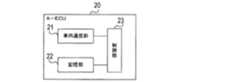
また、Aネットワーク2に接続されたA−ECU20は、車内通信部21,記憶部22,制御部23等を備える(図4)。
車内通信部21は、自装置が接続された車載ネットワークを介して、該車載ネットワークに接続されたECU等と通信を行う部位である。具体的には、自装置がAネットワーク2に接続されている場合には、車内通信部21は、Aネットワーク2に接続されたA−ECU20等と通信を行う。また、自装置がAネットワーク2とBネットワーク3に接続されている場合(ゲートウェイとして構成されている場合)には、車内通信部21は、Aネットワーク2に接続されたA−ECU20等と通信を行うと共に、Bネットワーク3に接続されたB−ECU40等と通信を行う。The A-ECU 20 connected to the
The in-
記憶部22は、フラッシュメモリやHDD等といったデータの書き換え可能な不揮発性メモリとして構成されている。記憶部22には、A−ECU20を制御するためのプログラムや各種データが保存されている。 The
制御部23は、CPU,ROM,RAM,I/O及びこれらを接続するバスライン等からなる周知のマイクロコンピュータを中心に構成される。制御部23は、ROMに記憶されているプログラムや、フラッシュメモリとして構成された記憶部22に記憶されているプログラムや、RAMにロードされたプログラムに従い各種処理を行う。 The
なお、B,Cネットワーク3,4に接続されたECUは、A−ECU20と同様に構成されているため、詳細な説明を省略する。
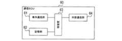
但し、Cネットワーク4に接続された通信ECU60は、次のように構成されている。通信ECU60は、車内通信部61,記憶部62,制御部63,外部通信部64等を備える(図5)。Note that the ECU connected to the B and C networks 3 and 4 is configured in the same manner as the A-ECU 20, and thus detailed description thereof is omitted.
However, the
車内通信部61,記憶部62,制御部63は、Aネットワーク2のA−ECU20に設けられている車内通信部21,記憶部22,制御部23と同様に構成されている。
外部通信部64は、書換ツール30と通信を行う部位であり、例えば、図示しないアンテナ等を介して書換ツール30と無線通信を行っても良いし、通信ECU60と書換ツール30とを一時的に接続する通信線を介して書換ツール30と通信を行っても良い。The in-
The
[処理]
次に、書換ツール30によりECUのリプログを行う際の処理について説明する。上述したように、リプログの際には、中継装置10は、書換ツール30と対象ECU(リプログの対象となるECU)との間の通信を中継する。[processing]
Next, processing when rewriting the ECU by the
(1)概要について
書換ツール30は、ユーザからいずれかのECUを対象ECUとするリプログを指示されると、中継装置10を経由して、対象ECUに対し、リプログを指示するコマンドであるリプログモード移行要求を送信する。そして、リプログが終了すると、書換ツール30は、対象ECUに対し、リプログの終了を通知するコマンドであるリプログモード終了要求を送信する。(1) About Outline When the
なお、書換ツール30は、複数の対象ECUに対し、同時期に並行してリプログを行うこともできる。このような場合には、書換ツール30は、各対象ECUに対し、個別にリプログモード移行要求を送信すると共に、新たなプログラムを構成するデータ(書換データ)を送信する。また、書換ツール30は、リプログが終了した対象ECUに対し、リプログの終了を通知するコマンドであるリプログモード終了要求を送信する。 Note that the
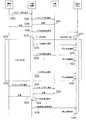
以下では、リプログが行われる際に書換ツール30,中継装置10,ECUにより行われる処理(リプログシーケンス)について説明する(図6)。
S100では、書換ツール30は、ユーザからの指示に応じて、中継装置10に対し、対象ECUにリプログの開始を指示するコマンド(対象ECUを送信先とするコマンド)であるリプログモード移行要求を送信する。なお、上述したように、ケース1(図1)の場合には、書換ツール30は、有線通信又は無線通信により、直接、中継装置10と通信を行い、ケース2(図2)の場合には、書換ツール30は、通信ECU60及びCネットワーク3を介して中継装置10と通信を行う。Hereinafter, a process (replog sequence) performed by the
In S100, the
S102では、中継装置10は、リプログモード移行要求を対象ECUに送信する。なお、ケース1の場合であれば、A−ECU20又はB−ECU40が対象ECUとなる。A−ECU20が対象ECUの場合、中継装置10は、Aネットワーク2を介して対象ECUと通信を行う。一方、B−ECU40が対象ECUの場合、中継装置10は、Aネットワーク2,ゲートウェイとなるA−ECU20,Bネットワーク2を介して、対象ECUと通信を行う。また、ケース2の場合であれば、A−ECU20が対象ECUとなり、中継装置10は、Aネットワーク2を介して対象ECUと通信を行う。 In S102, the
S104では、対象ECUは、リプログモード移行要求に応じて、中継装置10に対し、リプログを開始する旨の応答を示すコマンド(書換ツール30を送信先とするコマンド)を送信する。 In S104, the target ECU transmits a command (a command with the
S106では、中継装置10は、上記応答を書換ツール30に送信する。
そして、S108では、中継装置10は、リプログの対象とならないECUである対象外ECUに対し、データ送信停止要求を送信する。In S <b> 106, the
In S108, the
データ送信停止要求とは、対象外ECUに対し、予め定められた停止期間(一例として5s)にわたり、車載ネットワークへのデータ送信の停止を指示するコマンドである。なお、データ送信停止要求は、リプログ中における車載ネットワークへの全データの送信停止を指示するものであっても良いし、一部のデータ(例えば、重要度の低いデータ)の送信停止を指示するものであっても良い。また、データ送信停止要求は、さらに、対象外ECUに対し、リプログ中、車載ネットワークから必要なデータを受信できなくなっても、異常とみなさないようにすること(以後、ダイアグマスクと記載)を指示する。 The data transmission stop request is a command for instructing a non-target ECU to stop data transmission to the in-vehicle network over a predetermined stop period (for example, 5 s). The data transmission stop request may be an instruction to stop transmission of all data to the in-vehicle network during reprogramming, or may instruct to stop transmission of some data (for example, data with low importance). It may be a thing. In addition, the data transmission stop request further instructs the non-target ECU not to consider it abnormal even if it cannot receive the necessary data from the in-vehicle network during reprogressing (hereinafter referred to as “diag mask”). To do.
また、車載システム1を構成するECUのうち、対象ECUとなっていない全てのECUを、対象外ECUとしても良い。また、例えば、車載ネットワークの通信負荷等を考慮して、対象ECUとなっていないECUのうちの一部を、対象外ECUとして選択しても良い。 In addition, among ECUs constituting the in-vehicle system 1, all ECUs that are not the target ECUs may be excluded ECUs. For example, in consideration of the communication load of the in-vehicle network, a part of the ECUs that are not the target ECUs may be selected as the non-target ECUs.
すなわち、例えば、対象ECUと同じ車載ネットワークに接続されている他のECUを、全て対象外ECUとしても良い。具体例を挙げると、ケース1,2において、A−ECU20が対象ECUである場合、対象ECU以外の他のA−ECU20を対象外ECUとしても良い。また、ケース2において、B−ECU40が対象ECUである場合、対象ECU以外の他のB−ECU40を対象外ECUとしても良い。 That is, for example, all other ECUs connected to the same in-vehicle network as the target ECU may be excluded from the target ECU. As a specific example, when the A-ECU 20 is the target ECU in the
また、例えば、中継装置10と対象ECUとの間の通信の際に経由される車載ネットワークに接続されている他のECUを、対象外ECUとしても良い。具体例を挙げると、ケース1において、B−ECU40が対象ECUである場合、A−ECU20と、対象ECU以外の他のB−ECU40を対象外ECUとしても良い。 Further, for example, another ECU connected to an in-vehicle network that is routed during communication between the
また、ケース2においても、中継装置10と通信ECU60との間の通信の際に経由される車載ネットワークに接続されている他のECUを、対象外ECUとしても良い。具体例を挙げると、ケース2において、対象ECU以外の他のB−ECU40に加え、C−ECU50を対象外ECUとしても良い。 Also in
また、このようにして、車載ネットワーク単位で対象外ECUを定める場合には、対象となる車載ネットワークに接続されているECUのうち、一定の条件を満たす一部のECUを対象外ECUとしても良い。なお、このようにして一部のECUを対象外ECUとする場合には、対象外ECUにデータ送信停止要求を送信すると共に、対象外ECUと通信を行う全てのECUにダイアグマスクの指示を送信するのが好適である。 In addition, in this way, when determining the non-target ECUs in units of the in-vehicle network, some ECUs that satisfy certain conditions among the ECUs connected to the target in-vehicle network may be excluded from the target ECUs. . When some ECUs are excluded from the target ECU in this way, a data transmission stop request is transmitted to the non-target ECU, and a diagnosis mask instruction is transmitted to all the ECUs communicating with the non-target ECU. It is preferable to do this.
S110では、中継装置10は、一部のデータを車載ネットワークに送信するのを停止する。具体的には、例えば、リプログに必要なデータ以外データの送信を停止しても良い。 In S110, the
また、S112では、対象外ECUは、データ送信停止要求に応じて、停止期間にわたり車載ネットワークへのデータ送信を停止する。なお、対象外ECUは、車載ネットワークへのデータの送信を完全に停止しても良いし、一部のデータのみ送信を停止しても良い。また、この時、対象外ECUは、電力供給を停止する等して当該ECUの全部又は一部の機能を停止させることで、車載ネットワークへのデータ送信を停止させても良い。また、対象外ECUは、データ送信停止要求に応じて、停止期間にわたりダイアグマスクを行う。具体的には、車載ネットワークからのデータ受信に関する異常判定処理を行わないようにし、該データ受信の異常に対処するための処理が行われないようにする。なお、以後、車載ネットワークへの全部又は一部のデータの送信を停止すると共に、ダイアグマスクをした状態を、停止状態とも記載する。 In S112, the non-target ECU stops data transmission to the in-vehicle network over the stop period in response to the data transmission stop request. The non-target ECU may completely stop transmission of data to the in-vehicle network, or may stop transmission of only a part of the data. At this time, the non-target ECU may stop data transmission to the in-vehicle network by stopping all or a part of the functions of the ECU by stopping the power supply. Further, the non-target ECU performs diagnosis masking over the stop period in response to the data transmission stop request. Specifically, the abnormality determination process related to data reception from the in-vehicle network is not performed, and the process for dealing with the data reception abnormality is not performed. Hereinafter, transmission of all or a part of data to the in-vehicle network is stopped, and a state where the diagnosis masking is performed is also referred to as a stopped state.
S114では、書換ツール30と対象ECUとの間で、中継装置10等を介した通信を行い、対象ECUのリプログを行うリプログ処理が行われる。
具体的には、最初に、書換ツール30と対象ECUとの間で認証処理が行われ、書換ツール30により正規のリプログが行われるか否かが判定される。認証処理に成功すると、対象ECUは、記憶部に記憶されているプログラムを消去すると共に、中継装置10等を介して書換ツール30から書換データを取得し、該データを記憶部に書き込む。そして、書換データの書き込みが終了すると、ベリファイを行い、データの書き込みが正常に行われたかどうかをチェックし、書き込みが正常であった場合には、リプログ処理は終了する。In S <b> 114, a reprogram process is performed in which the
Specifically, first, an authentication process is performed between the rewriting
なお、リプログ処理が行われている間、中継装置10は、書換ツール30からリプログ処理を行うためのデータ(上述した認証処理を行うためのデータや書換データ等)を取得し、対象ECUに提供する。また、対象ECUからリプログ処理を行うためのデータを取得し、書換ツール30に提供する。 While the reprogram processing is being performed, the
また、リプログ処理が行われている間、中継装置10は、周期的なタイミング(一例として2.5s周期)にて、対象外ECUに対し、データ送信停止要求を送信する(S116,S120,S124)。データ送信停止要求を受信した対象外ECUは、S112と同様にして、その時点を起点として停止期間にわたり停止状態に移行する。換言すれば、その時点を起点として停止期間にわたり停止状態の継続期間を延長させる(S118,S122,S126)。 Further, while the reprogram processing is being performed, the
S128では、書換ツール30は、中継装置10に対し、対象ECUにリプログの終了を指示するコマンド(対象ECUを送信先とするコマンド)であるリプログモード終了要求を送信する。 In S128, the
S130では、中継装置10は、リプログモード終了要求を対象ECUに送信する。
S132では、対象ECUは、リプログモード終了要求に応じて、中継装置10に対し、リプログを終了する旨の応答を示すコマンド(書換ツール30を送信先とするコマンド)を送信する。In S130, the
In S132, the target ECU transmits a command (command with the
S134では、中継装置10は、上記応答を書換ツール30に送信する。
S136では、中継装置10は、車載ネットワークを介したデータ送信を再開する。また、データ送信停止要求の送信を終了する。In S <b> 134, the
In S136, the
S138では、対象外ECUは、前回データ送信停止要求を受信してから5sが経過したことにより、車載ネットワークへのデータ送信を再開すると共に、ダイアグマスクを解除する(換言すれば、停止状態を解除する)。 In S138, the non-target ECU restarts data transmission to the in-vehicle network and cancels the diagnostic mask (in other words, cancels the stopped state) after 5 seconds have elapsed since the last data transmission stop request was received. To do).
(2)異常検出処理について
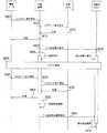
次に、リプログ中、書換ツール30からのデータ送信が途絶えた場合に、対象外ECUによる通信を再開させる異常検出処理について説明する(図7)。なお、本処理は、中継装置10にて定期的に実行される。(2) Abnormality Detection Process Next, an abnormality detection process for resuming communication by the non-target ECU when data transmission from the
S200では、中継装置10は、リプログ中か否かを判定する。具体的には、例えば、リプログカウンタの値が1以上であるか否か等に基づき、該判定を行っても良い。そして、肯定判定が得られた場合には(S200:Yes)、S205に移行すると共に、否定判定が得られた場合には(S205:No)、本処理を終了する。 In S200, the
S205では、中継装置10は、最後に書換ツール30からデータを受信した後、予め定められた異常検出時間が経過したか否かを判定する。そして、肯定判定が得られた場合には(S205:Yes)、S210に移行すると共に、否定判定が得られた場合には(S205:No)、本処理を終了する。 In S <b> 205, the
S210では、中継装置10は、対象外ECUでの停止状態(車載ネットワークへのデータ送信を停止し、且つ、ダイアグマスクをした状態)を解除させ、本処理を終了する。具体的には、例えば、中継装置10は、対象外ECUに対するデータ送信停止要求の送信を終了することで、停止状態を解除しても良い。また、例えば、中継装置10は、対象外ECUに対し、停止状態の解除を指示するコマンドであるデータ送信停止解除要求を送信しても良い。そして、対象外ECUは、データ送信停止解除要求の受信に応じて、停止状態を解除しても良い。 In S210, the
なお、中継装置10は、S205,S210において、同様にして、最後に対象ECUからデータを受信した後、予め定められた異常検出時間が経過したか否かを判定しても良い。そして、異常検出時間が経過した場合には、対象外ECUでの停止状態を解除させても良い。 Note that, in S205 and S210, the
[効果]
第1実施形態によれば、以下の効果が得られる。
(1)車載システム1によれば、書換ツール30により車載ネットワークを介して対象ECUのリプログが行われる際には、中継装置10から対象外ECUに対し、定期的にデータ送信停止要求が送信される。対象外ECUは、最初にデータ送信停止要求を受信すると、停止期間にわたり停止状態(車載ネットワークへのデータ送信を停止し、且つ、ダイアグマスクを行った状態)に移行し、以後、データ送信停止要求を受信する度に、停止状態の継続期間を延長する。そして、リプログが終了すると、中継装置10から対象外ECUへのデータ送信停止要求の送信を終了することで、対象外ECUの停止状態を解除する。[effect]
According to the first embodiment, the following effects can be obtained.
(1) According to the in-vehicle system 1, when the
このため、リプログの際、車載ネットワークの通信負荷が抑制され、リプログに必要なデータの送受信が迅速に行われる。したがって、外部に設置された装置により、車載システム1を構成するECUのリプログを遅滞なく行うことができる。また、リプログ処理の終了後は、対象外ECUの停止状態が確実に解除され、リプログ処理の終了後に対象外ECUの処理が妨げられることは無い。したがって、車載ネットワークを介してECUのリプログを円滑に行うことができる。 For this reason, the communication load of the in-vehicle network is suppressed at the time of replogging, and transmission / reception of data necessary for replogging is performed quickly. Therefore, the ECU installed in the in-vehicle system 1 can be re-logged without delay by an apparatus installed outside. In addition, after the replog process ends, the stop state of the non-target ECU is surely released, and the process of the non-target ECU is not hindered after the replog process ends. Therefore, the ECU can be smoothly reprogrammed through the in-vehicle network.
(2)また、対象ECUは、停止状態中、車載ネットワークへのデータ送信の停止に加え、ダイアグマスクが行われる。このため、対象外ECUがデータ送信を停止したことにより、故障等の異常事態が誤検出され、異常事態に対応するための処理が行われるのを防止できる。 (2) In addition, the target ECU performs diagnosis masking in addition to stopping data transmission to the in-vehicle network during the stop state. For this reason, it is possible to prevent an abnormal situation such as a failure from being erroneously detected and a process for responding to the abnormal situation from being performed due to the non-target ECU stopping the data transmission.
(3)また、データ送信停止要求を受信した対象外ECUは、停止期間にわたり停止状態を継続する構成となっているため、リプログ処理中、中継装置10からのデータ送信停止要求が途絶えた場合には、対象外ECUは、自発的に停止状態を解除する。このため、リプログ処理中に中継装置10に異常が生じても、対象外ECUは、確実に停止状態から復帰し、リプログが実行される前と同様に動作することができる。 (3) Further, since the non-target ECU that has received the data transmission stop request is configured to continue the stop state over the stop period, the data transmission stop request from the
(4)また、車両に搭載された中継装置10により、対象外ECUを停止状態に移行させる処理が行われる。このため、書換ツール30のような車外に設けられた装置により該処理を行う場合に比べ、該処理が不正に行われる危険性を低減でき、セキュリティ性が向上する。さらに、車外に設けられた装置にて該処理を行う際には、認証処理が必要となると考えられるが、車両に搭載された中継装置10にて停止状態に移行させる処理を行うことで、認証処理が不要となり、コストを抑えることができる。 (4) Moreover, the process which transfers non-target ECU to a stop state is performed by the
(5)また、車外に設けられた装置との通信に対応していない低性能のECUが車両に搭載されている場合が想定されるが、車両に搭載された中継装置10は、これらのECUとも通信が可能である。このため、リプログ中、低性能のECUにもデータ送信停止要求を送信し、停止状態に移行させることができる。 (5) Although it is assumed that a low-performance ECU that does not support communication with a device provided outside the vehicle is mounted on the vehicle, the
(6)また、中継装置10は、リプログ中、書換ツール30からデータを受信した後、異常検出時間が経過しても書換ツール30から新たなデータを受信できない場合には、対象外ECUの停止状態を解除させる。このため、何等かの異常により書換ツール30から対象ECUへのデータの送信が途絶した場合には、対象外ECUの停止状態を確実に解除できる。 (6) In addition, when the
特に、中継装置10は、リプログ中における書換ツール30からの通信の途絶を容易に検出できる。このため、中継装置10にて対象外ECUの停止状態を解除する構成としたことで、リプログ中における書換ツール30からの通信途絶に容易に対処することができる。 In particular, the
[第2実施形態]
次に、第2実施形態の車載システム1について説明する。第2実施形態の車載システム1は、第1実施形態と同様の構成を有しており、第1実施形態と同様にしてリプログシーケンスや異常検出処理が行われる。しかし、リプログシーケンスにおいて、リプログ処理の終了後における停止状態の解除方法が異なっている。[Second Embodiment]
Next, the vehicle-mounted system 1 of 2nd Embodiment is demonstrated. The in-vehicle system 1 of the second embodiment has the same configuration as that of the first embodiment, and a reprogram sequence and an abnormality detection process are performed in the same manner as in the first embodiment. However, in the replog sequence, the method for releasing the stop state after the replog process ends is different.
具体的には、第1実施形態では、リプログ処理の終了後、データ送信停止要求の送信を終了することで、停止状態を解除している。これに対し、第2実施形態では、中継装置10から対象外ECUにデータ送信停止解除要求を送信することで、停止状態を解除する。 Specifically, in the first embodiment, after the replog process ends, the stop state is canceled by ending the transmission of the data transmission stop request. On the other hand, in 2nd Embodiment, a stop state is cancelled | released by transmitting a data transmission stop cancellation request | requirement from the
以下では、第2実施形態のリプログシーケンスについて、第1実施形態との相違点を中心に説明する(図8)。
S300〜S336は、第1実施形態のリプログにおけるS100〜S136と同様であるため、説明を省略する。In the following, the replog sequence of the second embodiment will be described focusing on the differences from the first embodiment (FIG. 8).
Since S300 to S336 are the same as S100 to S136 in the replog of the first embodiment, description thereof is omitted.
S338では、中継装置10は、対象外ECUに対し、データ送信停止解除要求を送信する。
S340では、対象外ECUは、データ送信停止解除要求の受信に応じて停止状態を解除する。In S338, the
In S340, the non-target ECU cancels the stopped state in response to receiving the data transmission stop cancellation request.
[効果]
第2実施形態によれば、第1実施形態の効果に加え、以下の効果が得られる。
すなわち、第2実施形態では、リプログが終了すると、中継装置10から対象外ECUにデータ送信停止解除要求が送信され、対象外ECUは、これに応じて停止状態を解除する。このため、リプログ処理の終了時には、対象外ECUの停止状態を直ちに解除することができる。[effect]
According to the second embodiment, the following effects are obtained in addition to the effects of the first embodiment.
That is, in the second embodiment, when the replog is completed, a data transmission stop cancellation request is transmitted from the
[第3実施形態]
次に、第3実施形態の車載システム1について説明する。第3実施形態の車載システム1は、第1実施形態と同様の構成を有しているが、リプログシーケンスの内容が一部相違している。具体的には、リプログの開始時に対象外ECUを停止状態に移行させる処理や、リプログの終了時における停止状態の解除方法が異なっている。以下では、第1実施形態との相違点を中心に説明する。[Third Embodiment]
Next, the vehicle-mounted system 1 of 3rd Embodiment is demonstrated. The in-vehicle system 1 of the third embodiment has the same configuration as that of the first embodiment, but the contents of the replog sequence are partially different. Specifically, the process of shifting the non-target ECU to the stop state at the start of the reprogram and the method for canceling the stop state at the end of the reprogram are different. Below, it demonstrates centering on difference with 1st Embodiment.
(1)概要について
まず、第3実施形態のリプログシーケンスについて、第1実施形態のリプログシーケンスとの相違点を中心に説明する(図9)。(1) Outline First, the replog sequence of the third embodiment will be described focusing on the differences from the replog sequence of the first embodiment (FIG. 9).
S400〜S415は、第1実施形態のリプログにおけるS100〜S106と同様であるため、説明を省略する。
S420では、中継装置10は、対象外ECUにデータ送信停止要求を送信する。本処理は、後述するリプログ監視処理のS525に相当する。Since S400 to S415 are the same as S100 to S106 in the reprogram of the first embodiment, the description thereof is omitted.
In S420, the
なお、第3実施形態のデータ送信停止要求は、第1実施形態と同様にして、対象外ECUに対し、停止期間に限り停止状態に移行することを指示するものであっても良い。また、第1実施形態とは異なり、停止期間に制限されずに停止状態に移行することを指示するものであっても良い。 Note that the data transmission stop request of the third embodiment may instruct the non-target ECU to shift to the stop state only during the stop period, as in the first embodiment. Further, unlike the first embodiment, it may be instructed to shift to the stop state without being limited to the stop period.
S425は、第1実施形態のリプログにおけるS110と同様であるため、説明を省略する。
また、S430では、対象外ECUは、第1実施形態のS112と同様、停止状態に移行する。なお、データ送信停止要求に停止期間が設けられている場合であれば、停止期間に限り停止状態に移行する。Since S425 is the same as S110 in the reprogram of the first embodiment, a description thereof will be omitted.
In S430, the non-target ECU shifts to a stopped state, similar to S112 in the first embodiment. If the data transmission stop request is provided with a stop period, the stop state is entered only during the stop period.
S435では、第1実施形態と同様にしてリプログ処理が行われる。なお、データ送信停止要求に停止期間が設けられている場合であれば、リプログ処理中、中継装置10は、第1実施形態と同様にして対象外ECUに対し周期的にデータ送信停止要求を送信するが、そうでない場合には、データ送信停止要求を送信しない。 In S435, the reprogram processing is performed in the same manner as in the first embodiment. If a stop period is provided in the data transmission stop request, the
S440〜S455は、第1実施形態のリプログにおけるS128〜S134と同様であるため、説明を省略する。
S460では、中継装置10は、車載ネットワークを介したデータ送信を再開する。Since S440 to S455 are the same as S128 to S134 in the reprogram of the first embodiment, the description thereof is omitted.
In S460, the
そして、中継装置10は、対象外ECUに対し、データ送信停止解除要求を送信する(S465)。なお、本処理は、後述するリプログ監視処理のS535に相当する。また、対象外ECUは、データ送信停止解除要求の受信に応じて停止状態を解除する(S470)。 And the
なお、データ送信停止要求に停止期間が設けられている場合であれば、中継装置10にてデータ送信停止要求の送信を終了することで停止状態を解除しても良い。
(2)リプログ監視処理について
次に、中継装置10が、リプログ開始時に対象外ECUを停止状態に移行させると共に、リプログ終了時に対象外ECUの停止状態を解除するリプログ監視処理について説明する(図10)。なお、本処理は、中継装置10にて定期的に実行される。Note that if the data transmission stop request is provided with a stop period, the stop state may be canceled by terminating transmission of the data transmission stop request in the
(2) About Replog Monitoring Processing Next, a description will be given of the replog monitoring processing in which the
S500では、中継装置10は、書換ツール30から受信したコマンドに基づき、新たな対象ECUのリプログが開始されるか否かを判定する。具体的には、例えば、リプログの実行中でないECUを対象ECUとするリプログモード移行要求を受信した際には、新たな対象ECUのリプログが開始されたとみなしても良い。そして、肯定判定が得られた場合には(S500:Yes)、S505に移行し、否定判定が得られた場合には(S500:No)、S510に移行する。 In S500, based on the command received from the
S505では、中継装置10は、リプログが行われているECUの数を示すリプログカウンタをインクリメントし、S510に移行する。
S510では、中継装置10は、書換ツール30から受信したコマンドに基づき、対象ECUのリプログが終了したか否かを判定する。具体的には、例えば、対象ECUに対するリプログモード終了要求を受信した場合には、該対象ECUのリプログが終了したとみなしても良い。そして、肯定判定が得られた場合には(S510:Yes)、S515に移行し、否定判定が得られた場合には(S510:No)、S520に移行する。In S505, the
In S510, the
S515では、中継装置10は、リプログカウンタをデクリメントし、S520に移行する。
S520では、中継装置10は、リプログカウンタの値が0から1に変化したか否かを判定する(換言すれば、いずれのECUに対するリプログも行われていない状態で、新たにリプログが開始されたか否かを判定する)。そして、肯定判定が得られた場合には(S520:Yes)、S525に移行し、否定判定が得られた場合には(S520:No)、S530に移行する。In S515, the
In S520, the
S525では、中継装置10は、先に説明した図9のS420と同様にして、対象外ECUに対しデータ送信停止要求を送信し、S530に移行する。
なお、対象外ECUとするECUの選択方法によっては、リプログの実行中に新たな対象ECUのリプログが開始された場合、新たな対象ECUが接続されている車載ネットワークのECUに、データ送信停止要求等が送信されていない場合もある。このような場合には、該ECUを対象外ECUとしてデータ送信停止要求を送信するのが好適である。In S525, the
Depending on the method of selecting an ECU that is not a target ECU, if a new target ECU re-progress is started during execution of the re-prog, a data transmission stop request is sent to the ECU of the in-vehicle network to which the new target ECU is connected. Etc. may not be transmitted. In such a case, it is preferable to transmit a data transmission stop request using the ECU as a non-target ECU.
S530では、中継装置10は、リプログカウンタの値が1から0に変化したか否かを判定する(換言すれば、全てのECUのリプログが終了したか否かを判定する)。そして、肯定判定が得られた場合には(S530:Yes)、S535に移行し、否定判定が得られた場合には(S530:No)、本処理を終了する。 In S530, the
S535では、中継装置10は、対象外ECUの停止状態を解除し、本処理を終了する。
具体的には、データ送信停止要求に停止期間が設けられていない場合であれば、中継装置10は、対象外ECUに対し、データ送信停止解除要求を送信しても良い。一方、データ送信停止要求に停止期間が設けられている場合であれば、データ送信停止要求の送信を終了することで、対象外ECUの停止状態を解除しても良いし、対象外ECUにデータ送信停止解除要求を送信することで停止状態を解除しても良い。In S535, the
Specifically, if the stop period is not provided in the data transmission stop request, the
[効果]
第3実施形態によれば、第1実施形態の効果に加え、以下の効果が得られる。
すなわち、書換ツール30は、複数の対象ECUのリプログを同時期に並行して行うことができるが、中継装置10は、リプログ中、対象ECUの数をカウントする。そして、対象ECUの数が0になった際に、対象外ECUの停止状態を解除する。このため、複数のECUのリプログが同時期に並行して行われる場合であっても、全てのECUのリプログが終了した後に、確実に対象外ECUの停止状態を解除し、リプログの実行前と同様に動作させることができる。[effect]
According to the third embodiment, the following effects are obtained in addition to the effects of the first embodiment.
That is, the
[第4実施形態]
次に、第4実施形態の車載システム1について説明する。第4実施形態の車載システム1は、第3実施形態と同様の構成を有しているが、リプログ終了後に対象外ECUの停止状態を解除する際の処理が異なっている。具体的には、中継装置10にて行われるリプログ監視処理の内容が第3実施形態と相違しており、以下では、共通する部分については説明を省略し、相違点であるリプログ監視処理について説明する(図11)。[Fourth Embodiment]
Next, the vehicle-mounted system 1 of 4th Embodiment is demonstrated. The in-vehicle system 1 of the fourth embodiment has the same configuration as that of the third embodiment, but the processing for releasing the stop state of the non-target ECU after the completion of the replogging is different. Specifically, the contents of the replog monitoring process performed in the
S600では、中継装置10は、第3実施形態のリプログ監視処理のS500と同様にして、新たな対象ECUのリプログが開始されるか否かを判定する。そして、肯定判定が得られた場合には(S600:Yes)、S605に移行し、否定判定が得られた場合には(S600:No)、S615に移行する。 In S600, the
S605では、中継装置10は、リプログが行われているECUの数を示すリプログカウンタをインクリメントし、S610に移行する。
S610では、中継装置10は、リプログ時間の計測を開始し、S615に移行する。なお、リプログ時間とは、最後に開始された対象ECUのリプログの開始時点からの経過時間である。S610の処理により、新たな対象ECUに対するリプログが開始される度に、リプログ時間の計測値がリセットされ、最新のリプログの開始時点からの経過時間がリプログ時間として計測される。In S605, the
In S610, the
S615,S620は、第1実施形態のリプログ監視処理のS520,S525と同様の処理であるため、説明を省略する。
S625では、中継装置10は、リプログ時間が予め定められた終了時間を超えたか否かを判定する。そして、肯定判定が得られた場合には(S625:Yes)、S630に移行し、否定判定が得られた場合には(S625:No)、本処理を終了する。S615 and S620 are the same processes as S520 and S525 of the replog monitoring process of the first embodiment, and thus the description thereof is omitted.
In S625, the
S630では、第1実施形態のリプログ監視処理のS535と同様の処理が行われ、その後、本処理が終了する。
[効果]
第4実施形態によれば、第3実施形態の効果に加え、以下の効果が得られる。In S630, the same process as S535 of the replog monitoring process of the first embodiment is performed, and then this process ends.
[effect]
According to the fourth embodiment, the following effects are obtained in addition to the effects of the third embodiment.
すなわち、上述したように、書換ツール30は、複数の対象ECUのリプログを同時期に並行して行うことができるが、中継装置10は、最後に開始された対象ECUのリプログの開始時点からの経過時間であるリプログ時間を計測する。そして、リプログ時間が終了時間に達すると、対象外ECUの停止状態を解除する。このため、終了時間を適切な長さに設定することで、複数のECUのリプログが同時期に並行して行われる場合であっても、全てのECUのリプログが終了した後に、確実に対象外ECUの停止状態を解除し、リプログの実行前と同様に動作させることができる。 That is, as described above, the
[他の実施形態]
以上、本発明の実施形態について説明したが、本発明は上記実施形態に限定されることなく、種々の形態を採り得る。[Other Embodiments]
As mentioned above, although embodiment of this invention was described, this invention can take a various form, without being limited to the said embodiment.
(1)第1〜第4実施形態では、リプログシーケンスにより対象ECUに保存されているプログラムが書き換えられるが、プログラムに限定されることは無く、リプログシーケンスにより対象ECUに保存されているデータ(各種パラメータ等)を書き換える構成としても良い。 (1) In the first to fourth embodiments, the program stored in the target ECU is rewritten by the replog sequence, but is not limited to the program, and the data stored in the target ECU by the replog sequence (various types The parameter may be rewritten.
また、書換ツール30に対し、車載ネットワークを介して対象ECUと通信を行うことで対象ECUの故障診断等を行う機能を持たせても良い。そして、リプログシーケンスと同様の処理を行うことで、故障診断中に対象外ECUを停止状態に移行させると共に、故障診断の終了後には、対象外ECUの停止状態を解除しても良い。具体的には、リプログシーケンスにおけるリプログ処理において、書換ツール30による対象ECUの故障診断を行うようにしても良い。 Further, the
(2)第1〜第4実施形態では、中継装置10から対象外ECUにデータ送信停止要求を送信することで、対象外ECUを停止状態に移行させている。しかしながら、これに限らず、中継装置10から対象外ECUに対し、車載ネットワークへのデータ送信の停止を指示するコマンドと、ダイアグマスクを指示するコマンドとを別々に送信する構成としても良い。そして、対象外ECUは、各コマンドの受信に応じて車載ネットワークへのデータ送信を停止すると共に、ダイアグマスクを行うことで、停止状態への移行や継続を行っても良い。 (2) In the first to fourth embodiments, the non-target ECU is shifted to the stop state by transmitting a data transmission stop request from the
また、第2〜第4実施形態では、中継装置10から対象外ECUにデータ送信停止解除要求を送信することで、対象外ECUの停止状態を解除している。しかしながら、これに限らず、中継装置10から対象外ECUに対し、車載ネットワークへのデータ送信の停止の解除を指示するコマンドと、ダイアグマスクの解除を指示するコマンドとを別々に送信する構成としても良い。そして、対象外ECUは、各コマンドの受信に応じて車載ネットワークへのデータ送信を再開すると共に、ダイアグマスクを解除することで、停止状態を解除しても良い。 In the second to fourth embodiments, the stop state of the non-target ECU is canceled by transmitting a data transmission stop cancellation request from the
(3)上記実施形態における1つの構成要素が有する機能を複数の構成要素として分散させたり、複数の構成要素が有する機能を1つの構成要素に統合させたりしてもよい。また、上記実施形態の構成の少なくとも一部を、同様の機能を有する公知の構成に置き換えてもよい。また、上記実施形態の構成の一部を省略してもよい。また、上記実施形態の構成の少なくとも一部を、他の上記実施形態の構成に対して付加又は置換してもよい。なお、特許請求の範囲に記載した文言のみによって特定される技術思想に含まれるあらゆる態様が本発明の実施形態である。 (3) The functions of one constituent element in the above embodiment may be distributed as a plurality of constituent elements, or the functions of a plurality of constituent elements may be integrated into one constituent element. Further, at least a part of the configuration of the above embodiment may be replaced with a known configuration having the same function. Moreover, you may abbreviate | omit a part of structure of the said embodiment. In addition, at least a part of the configuration of the above embodiment may be added to or replaced with the configuration of the other embodiment. In addition, all the aspects included in the technical idea specified only by the wording described in the claim are embodiment of this invention.
(4)上述した車載システム1の他、書換ツール30や、車載システム1を構成する中継装置10やECU等、種々の形態で本発明を実現することもできる。この他にも、中継装置10やECUや書換ツール30としてコンピュータを機能させるためのプログラム、このプログラムを記録した媒体、中継装置10やECUや書換ツール30により実行される処理に相当する方法等、種々の形態で本発明を実現することもできる。 (4) In addition to the in-vehicle system 1 described above, the present invention can be realized in various forms such as the
[特許請求の範囲との対応]
上記実施形態の説明で用いた用語と、特許請求の範囲の記載に用いた用語との対応を示す。[Correspondence with Claims]
The correspondence between the terms used in the description of the above embodiment and the terms used in the description of the claims is shown.
書換ツール30が整備ツールの一例に相当する。
また、第1実施形態におけるリプログシーケンスのS108が停止指示ユニットの一例に、S112が停止ユニットの一例に、S114が整備処理,中継装置側取得ユニット,中継ユニット,ECU側取得ユニット,整備ユニットの一例に相当する。また、S116,S120,S124,S136が解除指示ユニットの一例に、S118,S122,S126が停止継続ユニットの一例に、S138が停止解除ユニットの一例に相当する。The
Also, S108 of the reprogram sequence in the first embodiment is an example of a stop instruction unit, S112 is an example of a stop unit, S114 is an example of a maintenance process, a relay device side acquisition unit, a relay unit, an ECU side acquisition unit, and a maintenance unit. It corresponds to. S116, S120, S124, and S136 correspond to an example of a release instruction unit, S118, S122, and S126 correspond to an example of a stop continuation unit, and S138 corresponds to an example of a stop release unit.
また、S108におけるデータ送信停止要求が停止コマンドの一例に相当し、S116,S120,S124におけるデータ送信停止要求が停止継続コマンドの一例に相当する。 Further, the data transmission stop request in S108 corresponds to an example of a stop command, and the data transmission stop request in S116, S120, and S124 corresponds to an example of a stop continuation command.
また、異常検出処理のS210が異常対応ユニットの一例に相当する。
また、第2実施形態におけるリプログシーケンスのS308が停止指示ユニットの一例に、S312が停止ユニットの一例に、S314が整備処理,中継装置側取得ユニット,中継ユニット,ECU側取得ユニット,整備ユニットの一例に相当する。また、S316,S320,S324,S338が解除指示ユニットの一例に、S340が停止解除ユニットの一例に相当する。Further, S210 of the abnormality detection process corresponds to an example of an abnormality handling unit.
Also, S308 of the reprogram sequence in the second embodiment is an example of a stop instruction unit, S312 is an example of a stop unit, S314 is an example of a maintenance process, a relay device side acquisition unit, a relay unit, an ECU side acquisition unit, and a maintenance unit. It corresponds to. S316, S320, S324, and S338 correspond to an example of a release instruction unit, and S340 corresponds to an example of a stop release unit.
また、S308におけるデータ送信停止要求が停止コマンドの一例に相当し、S316,S320,S324におけるデータ送信停止要求が停止継続コマンドの一例に相当し、S338におけるデータ送信停止解除要求が停止解除コマンドの一例に相当する。 Further, the data transmission stop request in S308 corresponds to an example of a stop command, the data transmission stop request in S316, S320, and S324 corresponds to an example of a stop continuation command, and the data transmission stop release request in S338 is an example of a stop release command. It corresponds to.
また、第3実施形態におけるリプログシーケンスのS420が停止指示ユニットの一例に、S430が停止ユニットの一例に、S435が整備処理,中継装置側取得ユニット,中継ユニット,ECU側取得ユニット,整備ユニットの一例に相当する。また、S465が解除指示ユニットの一例に、S470が停止解除ユニットの一例に相当する。 In addition, S420 of the reprogram sequence in the third embodiment is an example of a stop instruction unit, S430 is an example of a stop unit, S435 is an example of a maintenance process, a relay device side acquisition unit, a relay unit, an ECU side acquisition unit, and a maintenance unit. It corresponds to. Further, S465 corresponds to an example of a cancellation instruction unit, and S470 corresponds to an example of a stop cancellation unit.
また、S420におけるデータ送信停止要求が停止コマンドの一例に相当し、S465におけるデータ送信停止解除要求が停止解除コマンドの一例に相当する。
また、リプログ監視処理のS500が開始判定ユニットの一例に、S505,S515がカウントユニットの一例に、S510が終了判定ユニットの一例に、S530,S535が解除指示ユニットの一例に相当する。Further, the data transmission stop request in S420 corresponds to an example of a stop command, and the data transmission stop release request in S465 corresponds to an example of a stop release command.
Further, S500 of the replog monitoring process corresponds to an example of a start determination unit, S505 and S515 correspond to an example of a count unit, S510 corresponds to an example of an end determination unit, and S530 and S535 correspond to an example of a release instruction unit.
また、第4実施形態におけるリプログ監視処理のS600が開始判定ユニットの一例に、S625,S630が解除指示ユニットの一例に相当する。 In the fourth embodiment, S600 of the replog monitoring process corresponds to an example of a start determination unit, and S625 and S630 correspond to an example of a release instruction unit.
1…車載システム、2…Aネットワーク、3…Bネットワーク、4…Cネットワーク、0…中継装置、11…車内通信部、12…外部通信部、13…制御部、14…記憶部、20…A−ECU、21…車内通信部、22…記憶部、23…制御部、30…書換ツール、40…B−ECU、50…C−ECU、60…通信ECU、61…車内通信部、62…記憶部、63…制御部、64…外部通信部。 DESCRIPTION OF SYMBOLS 1 ... In-vehicle system, 2 ... A network, 3 ... B network, 4 ... C network, 0 ... Relay device, 11 ... In-vehicle communication part, 12 ... External communication part, 13 ... Control part, 14 ... Memory | storage part, 20 ... A -ECU, 21 ... In-vehicle communication unit, 22 ... Storage unit, 23 ... Control unit, 30 ... Rewriting tool, 40 ... B-ECU, 50 ... C-ECU, 60 ... Communication ECU, 61 ... In-vehicle communication unit, 62 ... Memory Part, 63 ... control part, 64 ... external communication part.
Claims (11)
Translated fromJapanese前記中継装置側取得ユニットが取得したデータを、前記整備処理の対象となる前記ECUである対象ECUに対し、前記車載ネットワークを介して提供する中継ユニット(S114,S314,S435)と、
前記整備処理が開始される際に、前記車載ネットワークを介して、前記対象ECU以外の前記ECUである対象外ECUに対し、前記車載ネットワークを介したデータ送信を停止した状態である停止状態への移行を指示する停止コマンドを送信する停止指示ユニット(S108,S308,S420)と、
前記整備処理が終了する際に、前記車載ネットワークを介して前記対象外ECUの前記停止状態の解除を指示する解除指示ユニット(S116,S120,S124,S136,S316,S320,S324,S338,S465,S530,S535,S625,S630)と、
を備えることを特徴とする中継装置(10)。Relay for acquiring data for performing the maintenance process from the maintenance tool (30) for performing the maintenance process (S114, S314, S435) for maintaining the ECU (20, 40) connected to the in-vehicle network (2, 3). An apparatus side acquisition unit (S114, S314, S435);
A relay unit (S114, S314, S435) that provides the data acquired by the relay device side acquisition unit to the target ECU, which is the ECU to be subjected to the maintenance process, via the in-vehicle network;
When the maintenance process is started, to the non-target ECU that is the ECU other than the target ECU via the on-vehicle network, the data transmission via the on-vehicle network is stopped. A stop instruction unit (S108, S308, S420) for transmitting a stop command for instructing transition;
When the maintenance process is finished, a release instruction unit (S116, S120, S124, S136, S316, S320, S324, S338, S465) that instructs the release of the stopped state of the non-target ECU via the in-vehicle network. S530, S535, S625, S630),
A relay device (10) comprising:
前記解除指示ユニットは、前記整備処理が行われている間、周期的なタイミングで、前記車載ネットワークを介して、前記対象外ECUに対し、予め定められた期間にわたり前記停止状態を継続させる停止継続コマンドを送信し、前記停止継続コマンドを送信しないことで、前記対象外ECUの前記停止状態の解除を指示すること、
を特徴とする中継装置。The relay device according to claim 1,
While the maintenance process is being performed, the release instruction unit continues to stop the non-target ECU for a predetermined period of time through the in-vehicle network at a periodic timing. Instructing the non-target ECU to release the stop state by sending a command and not sending the stop continuation command;
A relay device characterized by
前記解除指示ユニットは、前記整備処理が行われている間、周期的なタイミングで、前記車載ネットワークを介して、前記対象外ECUに対し、予め定められた期間にわたり前記停止状態を継続させる停止継続コマンドを送信すると共に、前記整備処理が終了する際に、前記車載ネットワークを介して、前記対象外ECUに対し、前記停止状態の解除を指示する停止解除コマンドを送信すること、
を特徴とする中継装置。The relay device according to claim 1,
While the maintenance process is being performed, the release instruction unit continues to stop the non-target ECU for a predetermined period of time through the in-vehicle network at a periodic timing. Sending a command and, when the maintenance process is finished, sending a stop release command for instructing release of the stop state to the non-target ECU via the in-vehicle network;
A relay device characterized by
前記整備ツールから取得したデータに基づき、いずれかの前記対象ECUに対する前記整備処理が開始されたか否かを判定する開始判定ユニット(S500)と、
前記整備ツールから取得したデータに基づき、いずれかの前記対象ECUに対する前記整備処理が終了したか否かを判定する終了判定ユニット(S510)と、
前記開始判定ユニットによる判定結果と前記終了判定ユニットとによる判定結果とに基づき、前記整備処理が行われている前記対象ECUの数をカウントするカウントユニット(S505,S515)と、をさらに備え、
前記解除指示ユニットは、前記カウントユニットによりカウントされた前記対象ECUの数が0になると、前記車載ネットワークを介して前記対象外ECUの前記停止状態の解除を指示すること、
を特徴とする中継装置。The relay device according to claim 1,
A start determination unit (S500) for determining whether or not the maintenance process for any of the target ECUs has been started based on data acquired from the maintenance tool;
An end determination unit (S510) for determining whether or not the maintenance process for any of the target ECUs is completed based on the data acquired from the maintenance tool;
A counting unit (S505, S515) that counts the number of the target ECUs on which the maintenance process is performed based on a determination result by the start determination unit and a determination result by the end determination unit;
The release instruction unit, when the number of the target ECUs counted by the count unit becomes 0, instructs the release of the stop state of the non-target ECUs via the in-vehicle network;
A relay device characterized by
前記整備ツールから取得したデータに基づき、いずれかの前記対象ECUに対する前記整備処理が開始されたか否かを判定する開始判定ユニット(S600)をさらに備え、
前記解除指示ユニットは、前記開始判定ユニットにより前記整備処理が開始されたと判定された時点を開始時点とし、最新の前記開始時点から予め定められた終了時間が経過すると、前記車載ネットワークを介して前記対象外ECUの前記停止状態の解除を指示すること、
をさらに備えることを特徴とする中継装置。The relay device according to claim 1,
A start determination unit (S600) for determining whether or not the maintenance process for any of the target ECUs is started based on the data acquired from the maintenance tool;
The release instruction unit has a time point when the start determination unit determines that the maintenance process has been started as a start time point, and when a predetermined end time has elapsed from the latest start time point, Instructing the release of the stop state of the non-target ECU;
The relay apparatus further comprising:
前記整備処理が行われている際、前記中継装置側取得ユニットが前記整備ツールから該整備処理を行うためのデータを取得できない期間が予め定められた異常検出時間に達した場合には、前記車載ネットワークを介して前記対象外ECUの前記停止状態の解除を指示する異常対応ユニット(S210)をさらに備えること、
を特徴とする中継装置。The relay device according to any one of claims 1 to 5,
When the maintenance process is being performed, if the period during which the relay device side acquisition unit cannot acquire data for performing the maintenance process from the maintenance tool has reached a predetermined abnormality detection time, An abnormality handling unit (S210) for instructing cancellation of the stopped state of the non-target ECU via a network;
A relay device characterized by
前記対象外ECUは、前記停止状態である場合には、さらに、前記車載ネットワークを介して前記ECUからデータを取得できないことを異常とみなさないこと、
を特徴とする中継装置。In the relay device according to any one of claims 1 to 6,
The non-target ECU, when it is in the stopped state, further does not regard the fact that data cannot be acquired from the ECU via the in-vehicle network as abnormal,
A relay device characterized by
前記ECU側取得ユニットが取得したデータに基づき、前記整備処理に関する処理を行う整備ユニット(S114,S314,S435)と、
前記整備処理が開始される際に、前記車載ネットワークを介して前記中継装置から停止コマンドを受信すると、前記車載ネットワークを介したデータ送信を停止した状態である停止状態に移行する停止ユニット(S112,S312,S430)と、
前記整備処理が終了する際に、前記車載ネットワークを介して行われる前記中継装置からの指示に応じて、前記停止状態を解除する停止解除ユニット(S138,S340,S470)と、
を備えることを特徴とするECU(20,40)。An ECU-side acquisition unit that acquires data for performing maintenance processing (S114, S314, S435) for the maintenance tool (30) to maintain its own device from the relay device (10) via the in-vehicle network (2, 3). S114, S314, S435),
Maintenance units (S114, S314, S435) that perform processing related to the maintenance process based on the data acquired by the ECU-side acquisition unit;
When the maintenance process is started, when a stop command is received from the relay device via the in-vehicle network, a stop unit that shifts to a stop state that is a state in which data transmission through the in-vehicle network is stopped (S112, S312 and S430),
A stop cancellation unit (S138, S340, S470) for releasing the stop state in response to an instruction from the relay device performed via the in-vehicle network when the maintenance process ends;
ECU (20, 40) characterized by comprising.
前記整備処理が行われている間、前記車載ネットワークを介して、前記中継装置から、予め定められた停止期間にわたり前記停止状態を継続させる停止継続コマンドを受信すると、該停止期間にわたり前記停止状態を継続させる停止継続ユニットを(S118,S122,S126)さらに備え、
前記停止解除ユニットは、前記停止継続コマンドの受信後、前記停止期間が経過した際に前記停止状態を解除することで、前記中継装置からの指示に応じて前記停止状態を解除すること、
を特徴とするECU。The ECU according to claim 8, wherein
While the maintenance process is being performed, when receiving a stop continuation command for continuing the stop state over a predetermined stop period from the relay device via the in-vehicle network, the stop state is changed over the stop period. A stop continuation unit for continuing (S118, S122, S126) is further provided,
The stop cancellation unit cancels the stop state according to an instruction from the relay device by releasing the stop state when the stop period has elapsed after receiving the stop continuation command;
ECU characterized by.
前記中継装置は、
前記ECUを整備する整備処理(S114,S314,S435)を行う整備ツール(30)から、前記整備処理を行うためのデータを取得する中継装置側取得ユニット(S114,S314,S435)と、
前記中継装置側取得ユニットが取得したデータを、前記整備処理の対象となる前記ECUである対象ECUに対し、前記車載ネットワークを介して提供する中継ユニット(S114,S314,S435)と、
前記整備処理が開始される際に、前記車載ネットワークを介して、前記対象ECU以外の前記ECUである対象外ECUに対し、前記車載ネットワークを介したデータ送信を停止した状態である停止状態への移行を指示する停止コマンドを送信する停止指示ユニット(S108,S308,S420)と、
前記整備処理が終了する際に、前記車載ネットワークを介して前記対象外ECUの前記停止状態の解除を指示する解除指示ユニット(S116,S120,S124,S136,S316,S320,S324,S338,S465,S530,S535,S625,S630)と、を備え、
前記ECUは、
前記整備ツールにより提供された、自装置を対象とする前記整備処理を行うためのデータを、前記車載ネットワークを介して前記中継装置から取得するECU側取得ユニット(S114,S314,S435)と、
前記ECU側取得ユニットが取得したデータに基づき、前記整備処理に関する処理を行う整備ユニット(S114,S314,S435)と、
前記整備処理が開始される際に、前記車載ネットワークを介して前記中継装置から前記停止コマンドを受信すると、前記停止状態に移行する停止ユニット(S112,S312,S430)と、
前記整備処理が終了する際に、前記中継装置からの前記指示に応じて、前記停止状態を解除する停止解除ユニット(S138,S340,S470)と、
を備えることを特徴とする車載システム(1)。An in-vehicle system (1) comprising an ECU (20, 40) and a relay device (10) connected to an in-vehicle network (2, 3),
The relay device is
A relay unit side acquisition unit (S114, S314, S435) for acquiring data for performing the maintenance process from a maintenance tool (30) for performing the maintenance process (S114, S314, S435) for maintaining the ECU;
A relay unit (S114, S314, S435) that provides the data acquired by the relay device side acquisition unit to the target ECU, which is the ECU to be subjected to the maintenance process, via the in-vehicle network;
When the maintenance process is started, to the non-target ECU that is the ECU other than the target ECU via the on-vehicle network, the data transmission via the on-vehicle network is stopped. A stop instruction unit (S108, S308, S420) for transmitting a stop command for instructing transition;
When the maintenance process is finished, a release instruction unit (S116, S120, S124, S136, S316, S320, S324, S338, S465) that instructs the release of the stopped state of the non-target ECU via the in-vehicle network. S530, S535, S625, S630),
The ECU
ECU side acquisition unit (S114, S314, S435) for acquiring data for performing the maintenance process for the device itself provided from the maintenance tool from the relay device via the in-vehicle network;
Maintenance units (S114, S314, S435) that perform processing related to the maintenance process based on the data acquired by the ECU-side acquisition unit;
When the maintenance process is started, when the stop command is received from the relay device via the in-vehicle network, a stop unit (S112, S312, S430) that shifts to the stop state;
A stop release unit (S138, S340, S470) for releasing the stop state in response to the instruction from the relay device when the maintenance process ends;
A vehicle-mounted system (1) comprising:
前記解除指示ユニットは、前記整備処理が行われている間、周期的なタイミングで、前記車載ネットワークを介して、前記対象外ECUに対し、予め定められた停止期間にわたり前記停止状態を継続させる停止継続コマンドを送信し、前記停止継続コマンドを送信しないことで、前記対象外ECUの前記停止状態の解除を指示し、
前記ECUは、前記整備処理が行われている間、前記車載ネットワークを介して、前記中継装置から、前記停止継続コマンドを受信すると、前記停止期間にわたり前記停止状態を継続させる停止継続ユニットを(S118,S122,S126)さらに備え、
前記停止解除ユニットは、前記停止継続コマンドの受信後、前記停止期間が経過した際に前記停止状態を解除することで、前記中継装置からの指示に応じて前記停止状態を解除すること、
を特徴とする車載システム。The in-vehicle system according to claim 10,
The cancellation instruction unit stops the non-target ECU from continuing the stop state over a predetermined stop period via the in-vehicle network at a periodic timing while the maintenance process is being performed. By sending a continuation command and not sending the stop continuation command, instructing the release of the stop state of the non-target ECU,
When the ECU receives the stop continuation command from the relay device via the in-vehicle network while the maintenance process is being performed, the ECU sets a stop continuation unit that continues the stop state over the stop period (S118). , S122, S126)
The stop cancellation unit cancels the stop state according to an instruction from the relay device by releasing the stop state when the stop period has elapsed after receiving the stop continuation command;
In-vehicle system characterized by
Priority Applications (5)
| Application Number | Priority Date | Filing Date | Title |
|---|---|---|---|
| JP2015145759AJP6281535B2 (en) | 2015-07-23 | 2015-07-23 | Relay device, ECU, and in-vehicle system |
| CN201680042329.1ACN107852352B (en) | 2015-07-23 | 2016-07-14 | Relay device, electronic control device, and in-vehicle system |
| US15/743,777US10489141B2 (en) | 2015-07-23 | 2016-07-14 | Relay device, electronic control unit, and vehicle-mounted system |
| DE112016003325.7TDE112016003325B4 (en) | 2015-07-23 | 2016-07-14 | forwarding device, electronic control unit and vehicle-mounted system |
| PCT/JP2016/070770WO2017014133A1 (en) | 2015-07-23 | 2016-07-14 | Relay device, electronic control unit, and vehicle-mounted system |
Applications Claiming Priority (1)
| Application Number | Priority Date | Filing Date | Title |
|---|---|---|---|
| JP2015145759AJP6281535B2 (en) | 2015-07-23 | 2015-07-23 | Relay device, ECU, and in-vehicle system |
Publications (2)
| Publication Number | Publication Date |
|---|---|
| JP2017028523A JP2017028523A (en) | 2017-02-02 |
| JP6281535B2true JP6281535B2 (en) | 2018-02-21 |
Family
ID=57835009
Family Applications (1)
| Application Number | Title | Priority Date | Filing Date |
|---|---|---|---|
| JP2015145759AActiveJP6281535B2 (en) | 2015-07-23 | 2015-07-23 | Relay device, ECU, and in-vehicle system |
Country Status (5)
| Country | Link |
|---|---|
| US (1) | US10489141B2 (en) |
| JP (1) | JP6281535B2 (en) |
| CN (1) | CN107852352B (en) |
| DE (1) | DE112016003325B4 (en) |
| WO (1) | WO2017014133A1 (en) |
Families Citing this family (43)
| Publication number | Priority date | Publication date | Assignee | Title |
|---|---|---|---|---|
| US10479297B2 (en)* | 2016-10-27 | 2019-11-19 | Sumitomo Electric Industries, Ltd. | Control apparatus, program updating method, and computer program |
| JP6515911B2 (en)* | 2016-12-16 | 2019-05-22 | トヨタ自動車株式会社 | In-vehicle network system |
| JP6682019B2 (en)* | 2017-01-25 | 2020-04-15 | 日立オートモティブシステムズ株式会社 | Program update system and program writing device |
| JP6785720B2 (en)* | 2017-05-29 | 2020-11-18 | 日立オートモティブシステムズ株式会社 | Vehicle control device and program rewriting method |
| JP2019009639A (en)* | 2017-06-26 | 2019-01-17 | 株式会社オートネットワーク技術研究所 | On-vehicle communication system, on-vehicle relay device, and relay program |
| WO2019221118A1 (en)* | 2018-05-15 | 2019-11-21 | 株式会社デンソー | Electronic control unit and session establishment program |
| JP7131475B2 (en)* | 2018-05-15 | 2022-09-06 | 株式会社デンソー | Electronic controller, session establishment program and control program |
| WO2020022265A1 (en) | 2018-07-25 | 2020-01-30 | 株式会社デンソー | Electronic control system for vehicle, method for determining authorization of program update, and program for determining authorization of program update |
| JP7379892B2 (en) | 2018-07-25 | 2023-11-15 | 株式会社デンソー | Vehicle electronic control systems, vehicle-side systems, and mobile terminals |
| JP7354658B2 (en) | 2018-08-10 | 2023-10-03 | 株式会社デンソー | Vehicle electronic control system, progress display screen display control method, and progress display screen display control program |
| JP6973449B2 (en) | 2018-08-10 | 2021-12-01 | 株式会社デンソー | Electronic control system for vehicles, download judgment method for distribution packages, and download judgment program for distribution packages |
| JP7156192B2 (en) | 2018-08-10 | 2022-10-19 | 株式会社デンソー | VEHICLE MASTER DEVICE, NON-REWRITE TARGET POWER MANAGEMENT METHOD AND NON-REWRITE TARGET POWER MANAGEMENT PROGRAM |
| WO2020032121A1 (en) | 2018-08-10 | 2020-02-13 | 株式会社デンソー | Vehicular master device, update data verification method, and update data verification program |
| JP7439402B2 (en) | 2018-08-10 | 2024-02-28 | 株式会社デンソー | Display control device, rewriting progress display control method, and rewriting progress display control program |
| JP7003976B2 (en) | 2018-08-10 | 2022-01-21 | 株式会社デンソー | Vehicle master device, update data verification method and update data verification program |
| JP7427879B2 (en) | 2018-08-10 | 2024-02-06 | 株式会社デンソー | Vehicle master device, group management method to be rewritten, and group management program to be rewritten |
| JP7024765B2 (en) | 2018-08-10 | 2022-02-24 | 株式会社デンソー | Vehicle master device, update data distribution control method, and update data distribution control program |
| JP7047819B2 (en) | 2018-08-10 | 2022-04-05 | 株式会社デンソー | Electronic control device, electronic control system for vehicles, activation execution control method and activation execution control program |
| JP7346956B2 (en) | 2018-08-10 | 2023-09-20 | 株式会社デンソー | Vehicle program rewriting system, vehicle master device, progress state synchronous control method, and progress state synchronous control program |
| JP7111074B2 (en) | 2018-08-10 | 2022-08-02 | 株式会社デンソー | Vehicle master device, security access key management method, security access key management program, and vehicle electronic control system |
| JP7484096B2 (en) | 2018-08-10 | 2024-05-16 | 株式会社デンソー | Electronic control device, rewrite execution control method, and rewrite execution control program |
| JP7354631B2 (en) | 2018-08-10 | 2023-10-03 | 株式会社デンソー | Electronic control device, electronic control system for vehicle, method for determining consistency of differential data, and program for determining consistency of differential data |
| JP6973450B2 (en) | 2018-08-10 | 2021-12-01 | 株式会社デンソー | Vehicle master device, installation instruction judgment method and installation instruction judgment program |
| JP7367359B2 (en) | 2018-08-10 | 2023-10-24 | 株式会社デンソー | Vehicle electronic control system, file transfer control method, file transfer control program and device |
| JP7419689B2 (en) | 2018-08-10 | 2024-01-23 | 株式会社デンソー | Vehicle electronic control system, center device, vehicle master device, display control information transmission control method, display control information reception control method, display control information transmission control program, and display control information reception control program |
| JP7159989B2 (en) | 2018-08-10 | 2022-10-25 | 株式会社デンソー | Vehicle master device, vehicle electronic control system, activation request instruction method, and activation request instruction program |
| JP7400232B2 (en) | 2018-08-10 | 2023-12-19 | 株式会社デンソー | Electronic control device, retry point identification method, retry point identification program, and vehicle electronic control system |
| JP7115429B2 (en) | 2018-08-10 | 2022-08-09 | 株式会社デンソー | VEHICLE MASTER DEVICE, ROLLBACK EXECUTION CONTROL METHOD AND ROLLBACK EXECUTION CONTROL PROGRAM |
| JP7176305B2 (en)* | 2018-09-03 | 2022-11-22 | 株式会社オートネットワーク技術研究所 | Relay device, relay method and computer program |
| JP6548058B1 (en)* | 2018-09-28 | 2019-07-24 | パナソニックIpマネジメント株式会社 | INFORMATION PROCESSING APPARATUS, PROGRAM, AND INFORMATION PROCESSING SYSTEM |
| JP7342442B2 (en)* | 2018-11-14 | 2023-09-12 | 株式会社リコー | Information processing device, information processing method, program |
| CN113168382B (en)* | 2018-11-28 | 2024-07-12 | 株式会社自动网络技术研究所 | Monitoring device, monitoring program, and monitoring method |
| JP7088075B2 (en)* | 2019-02-22 | 2022-06-21 | 株式会社デンソー | Electronic control device |
| FR3097988B1 (en)* | 2019-06-25 | 2021-06-04 | Renault Sas | Method of dialogue with a computer on a vehicle's on-board bus. |
| JP7283359B2 (en)* | 2019-11-19 | 2023-05-30 | 株式会社オートネットワーク技術研究所 | In-vehicle update device and update processing program |
| WO2021215188A1 (en) | 2020-04-21 | 2021-10-28 | 株式会社デンソー | Vehicular electronic control system, data initialization method, center device, vehicular master device, initialization package delivery program, and data initialization program |
| CN112558990A (en)* | 2020-12-15 | 2021-03-26 | 交控科技股份有限公司 | Maintenance and upgrading method and system for vehicle-mounted safety computer |
| WO2022185370A1 (en)* | 2021-03-01 | 2022-09-09 | 株式会社オートネットワーク技術研究所 | In-vehicle device, program, and information processing method |
| CN113655737B (en)* | 2021-06-29 | 2023-05-26 | 北京峰智睿联科技有限公司 | Vehicle-mounted electronic controller rapid upgrading system and method transmitted through CAN |
| JP7596962B2 (en)* | 2021-07-28 | 2024-12-10 | トヨタ自動車株式会社 | Center, method, and program |
| JP7668204B2 (en)* | 2021-10-26 | 2025-04-24 | 本田技研工業株式会社 | In-vehicle control system |
| WO2023095258A1 (en)* | 2021-11-25 | 2023-06-01 | 日本電信電話株式会社 | Monitoring device, monitoring method, and monitoring program |
| JP2023158830A (en)* | 2022-04-19 | 2023-10-31 | 株式会社デンソー | Electronic control device, repro implementation method, and repro implementation program |
Family Cites Families (55)
| Publication number | Priority date | Publication date | Assignee | Title |
|---|---|---|---|---|
| US9443358B2 (en)* | 1995-06-07 | 2016-09-13 | Automotive Vehicular Sciences LLC | Vehicle software upgrade techniques |
| JPH09288573A (en)* | 1996-04-23 | 1997-11-04 | Mitsubishi Electric Corp | In-vehicle control device |
| JP4622177B2 (en) | 2001-07-06 | 2011-02-02 | 株式会社デンソー | Failure diagnosis system, vehicle management device, server device, and inspection diagnosis program |
| US6694235B2 (en) | 2001-07-06 | 2004-02-17 | Denso Corporation | Vehicular relay device, in-vehicle communication system, failure diagnostic system, vehicle management device, server device and detection and diagnostic program |
| JP4942261B2 (en) | 2001-07-31 | 2012-05-30 | 株式会社デンソー | Vehicle relay device and in-vehicle communication system |
| JP2003172199A (en)* | 2001-12-05 | 2003-06-20 | Nissan Motor Co Ltd | Program rewriting system for vehicle electronic control unit |
| JP2007507016A (en)* | 2003-06-24 | 2007-03-22 | ローベルト ボッシュ ゲゼルシャフト ミット ベシュレンクテル ハフツング | Software update method for electronic control device by flash programming via serial interface and state automatic device corresponding thereto |
| JP4361902B2 (en)* | 2003-12-15 | 2009-11-11 | 株式会社日立製作所 | In-vehicle control device information update method, update information communication system, vehicle-mounted control device, and information management base station device |
| US20060259207A1 (en)* | 2005-04-20 | 2006-11-16 | Denso Corporation | Electronic control system for automobile |
| JP2007011734A (en)* | 2005-06-30 | 2007-01-18 | Denso Corp | On-vehicle control unit |
| JP4302113B2 (en)* | 2006-03-24 | 2009-07-22 | 三菱電機株式会社 | In-vehicle control device |
| JP4724095B2 (en) | 2006-11-21 | 2011-07-13 | 株式会社オートネットワーク技術研究所 | Relay connection unit and in-vehicle communication system |
| JP2008155736A (en)* | 2006-12-22 | 2008-07-10 | Fujitsu Ten Ltd | Electronic control device |
| JP2008199253A (en)* | 2007-02-13 | 2008-08-28 | Fujitsu Ten Ltd | Abnormality diagnosis system and diagnostic information management device |
| JP4363471B2 (en)* | 2007-08-03 | 2009-11-11 | 株式会社デンソー | Fault code storage management device and storage management device |
| CN101470411B (en)* | 2007-12-28 | 2011-06-01 | 联合汽车电子有限公司 | System and method for safely updating ECU data |
| JP5141377B2 (en)* | 2008-05-27 | 2013-02-13 | 株式会社デンソー | Program rewriting system |
| EP2586662B1 (en)* | 2010-06-23 | 2018-07-18 | Toyota Jidosha Kabushiki Kaisha | Program update device |
| EP2602157B1 (en)* | 2010-08-03 | 2015-04-01 | Honda Motor Co., Ltd. | Vehicle program rewriting system |
| JP2012082735A (en)* | 2010-10-08 | 2012-04-26 | Denso Corp | Engine revolution stop control device |
| JPWO2012056773A1 (en)* | 2010-10-29 | 2014-03-20 | 本田技研工業株式会社 | Program rewriting system for vehicles |
| JP5629927B2 (en)* | 2010-11-12 | 2014-11-26 | クラリオン株式会社 | Online update method for in-vehicle devices |
| KR20120071243A (en)* | 2010-12-22 | 2012-07-02 | 한국전자통신연구원 | Apparatus for updating software of vehicle and method thereof |
| JP5829839B2 (en)* | 2011-06-16 | 2015-12-09 | 富士通テン株式会社 | Server apparatus, program providing system, program providing method, and program |
| KR101360705B1 (en)* | 2011-09-22 | 2014-02-07 | 기아자동차주식회사 | Vehicle Upgrade System and Method thereof |
| JP5708940B2 (en)* | 2012-08-22 | 2015-04-30 | トヨタ自動車株式会社 | Information management device, information communication system |
| KR20140038160A (en)* | 2012-09-20 | 2014-03-28 | 한국전자통신연구원 | Method for updating ecu in system based on autosar and apparatus for the same |
| JP5949417B2 (en)* | 2012-10-09 | 2016-07-06 | 株式会社デンソー | Relay device |
| US8813061B2 (en)* | 2012-10-17 | 2014-08-19 | Movimento Group | Module updating device |
| JP6056424B2 (en) | 2012-11-29 | 2017-01-11 | 株式会社デンソー | In-vehicle program update device |
| JP6192334B2 (en)* | 2013-03-29 | 2017-09-06 | 日立オートモティブシステムズ株式会社 | Electronic control device program rewriting method, electronic control device, and rewriting device |
| KR101463604B1 (en)* | 2013-04-24 | 2014-11-20 | 주식회사 오비고 | Method, system, and computer-readable recording media for updating electronic control unit |
| JP5702829B2 (en)* | 2013-05-23 | 2015-04-15 | 本田技研工業株式会社 | Relay device |
| JP5975964B2 (en)* | 2013-10-18 | 2016-08-23 | 富士通株式会社 | Information processing program, information processing method, information processing apparatus, and information processing system |
| US9529584B2 (en)* | 2013-11-06 | 2016-12-27 | General Motors Llc | System and method for preparing vehicle for remote reflash event |
| JP5949732B2 (en)* | 2013-11-27 | 2016-07-13 | 株式会社オートネットワーク技術研究所 | Program update system and program update method |
| JP5858062B2 (en) | 2014-02-03 | 2016-02-10 | ダイキン工業株式会社 | Air conditioning system |
| JP6206232B2 (en)* | 2014-02-13 | 2017-10-04 | 株式会社デンソー | In-vehicle control device |
| CN103812944B (en)* | 2014-02-26 | 2017-12-19 | 安徽安凯汽车股份有限公司 | A kind of method for remote updating for electric automobile ECU |
| US9229704B2 (en)* | 2014-04-01 | 2016-01-05 | Ford Global Technologies, Llc | Smart vehicle reflash with battery state of charge (SOC) estimator |
| DE102014008479A1 (en)* | 2014-06-07 | 2015-12-17 | Audi Ag | Motor vehicle control unit with power-saving mode for a parking phase |
| US10310838B2 (en)* | 2014-06-18 | 2019-06-04 | Hitachi Automotive Systems, Ltd. | Vehicle-mounted program writing device |
| CN110321149B (en)* | 2014-06-19 | 2023-08-25 | 日立安斯泰莫株式会社 | Vehicle program writing device |
| JP6618480B2 (en)* | 2014-11-12 | 2019-12-11 | パナソニック インテレクチュアル プロパティ コーポレーション オブ アメリカPanasonic Intellectual Property Corporation of America | Update management method, update management system, and control program |
| US10387141B2 (en)* | 2014-12-30 | 2019-08-20 | Visteon Global Technologies, Inc. | Upgradable firmware system |
| US9841970B2 (en)* | 2015-01-13 | 2017-12-12 | Ford Global Technologies, Llc | Vehicle control update methods and systems |
| US9529580B2 (en)* | 2015-01-21 | 2016-12-27 | Ford Global Technologies, Llc | Vehicle control update methods and systems |
| JP6434994B2 (en)* | 2015-01-26 | 2018-12-05 | 日立オートモティブシステムズ株式会社 | In-vehicle control device, program writing device, program generation device, and program |
| US20160266886A1 (en)* | 2015-03-10 | 2016-09-15 | GM Global Technology Operations LLC | Performing a vehicle update |
| JP6216730B2 (en)* | 2015-03-16 | 2017-10-18 | 日立オートモティブシステムズ株式会社 | Software update device and software update method |
| WO2016158547A1 (en)* | 2015-03-30 | 2016-10-06 | 本田技研工業株式会社 | Program rewriting device and program rewriting method |
| JP2016218932A (en)* | 2015-05-26 | 2016-12-22 | 京セラ株式会社 | Software update device and software update system |
| EP3101535B1 (en)* | 2015-06-01 | 2022-04-13 | OpenSynergy GmbH | Method for updating a control unit for an automotive vehicle, control unit for an automotive vehicle, and computer program product |
| US9836300B2 (en)* | 2015-06-16 | 2017-12-05 | Lear Corporation | Method for updating vehicle ECUs using differential update packages |
| US10042635B2 (en)* | 2015-06-16 | 2018-08-07 | Lear Corporation | Method for wireless remote updating vehicle software |
- 2015
- 2015-07-23JPJP2015145759Apatent/JP6281535B2/enactiveActive
- 2016
- 2016-07-14CNCN201680042329.1Apatent/CN107852352B/enactiveActive
- 2016-07-14DEDE112016003325.7Tpatent/DE112016003325B4/enactiveActive
- 2016-07-14WOPCT/JP2016/070770patent/WO2017014133A1/ennot_activeCeased
- 2016-07-14USUS15/743,777patent/US10489141B2/enactiveActive
Also Published As
| Publication number | Publication date |
|---|---|
| CN107852352A (en) | 2018-03-27 |
| DE112016003325T5 (en) | 2018-04-19 |
| WO2017014133A1 (en) | 2017-01-26 |
| JP2017028523A (en) | 2017-02-02 |
| CN107852352B (en) | 2020-10-27 |
| US20180203685A1 (en) | 2018-07-19 |
| DE112016003325B4 (en) | 2025-01-30 |
| US10489141B2 (en) | 2019-11-26 |
Similar Documents
| Publication | Publication Date | Title |
|---|---|---|
| JP6281535B2 (en) | Relay device, ECU, and in-vehicle system | |
| JP6665728B2 (en) | In-vehicle update device, in-vehicle update system and communication device update method | |
| JP6418217B2 (en) | Information aggregation method executed in communication system | |
| JP5741480B2 (en) | Communication system, relay device, and power supply control method | |
| JP6369341B2 (en) | In-vehicle communication system | |
| US7054728B2 (en) | Rewrite control apparatus for onboard program | |
| JP7192747B2 (en) | In-vehicle relay device and information processing method | |
| JP7147525B2 (en) | Communication device and control method | |
| KR102013050B1 (en) | Control means, a rewriting device of the on-board program having the same, and a rewriting method of the on-board program | |
| JP2009110529A (en) | In-vehicle program rewrite control system | |
| US20070239329A1 (en) | Program management system | |
| JP2010136544A (en) | Communication error determining apparatus and communication error determining method for vehicle control system | |
| JP2003143164A (en) | Control device and communication failure detection method | |
| JP2010137612A (en) | Communication system of vehicular control unit | |
| JP6221972B2 (en) | Firmware update system and update control method | |
| JP6702161B2 (en) | In-vehicle electronic control unit | |
| JP2009087107A (en) | Vehicle control system | |
| JP6344036B2 (en) | Information processing apparatus for vehicle | |
| JP5029123B2 (en) | Electronic control device and communication system | |
| JP6516719B2 (en) | Elevator program rewriting system and program rewriting method | |
| JP2020189586A (en) | Data rewriting method and data rewriting system | |
| JP4214974B2 (en) | Communication data block transmission method | |
| JP2009010851A (en) | On-vehicle gateway device | |
| JP4948583B2 (en) | Control system | |
| WO2019235286A1 (en) | Communication device and control method |
Legal Events
| Date | Code | Title | Description |
|---|---|---|---|
| A621 | Written request for application examination | Free format text:JAPANESE INTERMEDIATE CODE: A621 Effective date:20170613 | |
| TRDD | Decision of grant or rejection written | ||
| A01 | Written decision to grant a patent or to grant a registration (utility model) | Free format text:JAPANESE INTERMEDIATE CODE: A01 Effective date:20171226 | |
| A61 | First payment of annual fees (during grant procedure) | Free format text:JAPANESE INTERMEDIATE CODE: A61 Effective date:20180108 | |
| R151 | Written notification of patent or utility model registration | Ref document number:6281535 Country of ref document:JP Free format text:JAPANESE INTERMEDIATE CODE: R151 | |
| R250 | Receipt of annual fees | Free format text:JAPANESE INTERMEDIATE CODE: R250 | |
| R250 | Receipt of annual fees | Free format text:JAPANESE INTERMEDIATE CODE: R250 | |
| R250 | Receipt of annual fees | Free format text:JAPANESE INTERMEDIATE CODE: R250 | |
| R250 | Receipt of annual fees | Free format text:JAPANESE INTERMEDIATE CODE: R250 | |
| R250 | Receipt of annual fees | Free format text:JAPANESE INTERMEDIATE CODE: R250 |