JP6279620B2 - Storage device - Google Patents
Storage deviceDownload PDFInfo
- Publication number
- JP6279620B2 JP6279620B2JP2015559650AJP2015559650AJP6279620B2JP 6279620 B2JP6279620 B2JP 6279620B2JP 2015559650 AJP2015559650 AJP 2015559650AJP 2015559650 AJP2015559650 AJP 2015559650AJP 6279620 B2JP6279620 B2JP 6279620B2
- Authority
- JP
- Japan
- Prior art keywords
- flash memory
- storage area
- virtual
- raid controller
- fmd
- Prior art date
- Legal status (The legal status is an assumption and is not a legal conclusion. Google has not performed a legal analysis and makes no representation as to the accuracy of the status listed.)
- Expired - Fee Related
Links
Images


Classifications
- G—PHYSICS
- G06—COMPUTING OR CALCULATING; COUNTING
- G06F—ELECTRIC DIGITAL DATA PROCESSING
- G06F11/00—Error detection; Error correction; Monitoring
- G06F11/07—Responding to the occurrence of a fault, e.g. fault tolerance
- G06F11/16—Error detection or correction of the data by redundancy in hardware
- G06F11/20—Error detection or correction of the data by redundancy in hardware using active fault-masking, e.g. by switching out faulty elements or by switching in spare elements
- G06F11/2053—Error detection or correction of the data by redundancy in hardware using active fault-masking, e.g. by switching out faulty elements or by switching in spare elements where persistent mass storage functionality or persistent mass storage control functionality is redundant
- G06F11/2094—Redundant storage or storage space
- G—PHYSICS
- G06—COMPUTING OR CALCULATING; COUNTING
- G06F—ELECTRIC DIGITAL DATA PROCESSING
- G06F11/00—Error detection; Error correction; Monitoring
- G06F11/07—Responding to the occurrence of a fault, e.g. fault tolerance
- G06F11/08—Error detection or correction by redundancy in data representation, e.g. by using checking codes
- G06F11/10—Adding special bits or symbols to the coded information, e.g. parity check, casting out 9's or 11's
- G06F11/1076—Parity data used in redundant arrays of independent storages, e.g. in RAID systems
- G06F11/108—Parity data distribution in semiconductor storages, e.g. in SSD
- G—PHYSICS
- G06—COMPUTING OR CALCULATING; COUNTING
- G06F—ELECTRIC DIGITAL DATA PROCESSING
- G06F3/00—Input arrangements for transferring data to be processed into a form capable of being handled by the computer; Output arrangements for transferring data from processing unit to output unit, e.g. interface arrangements
- G06F3/06—Digital input from, or digital output to, record carriers, e.g. RAID, emulated record carriers or networked record carriers
- G06F3/0601—Interfaces specially adapted for storage systems
- G06F3/0602—Interfaces specially adapted for storage systems specifically adapted to achieve a particular effect
- G06F3/0614—Improving the reliability of storage systems
- G06F3/0619—Improving the reliability of storage systems in relation to data integrity, e.g. data losses, bit errors
- G—PHYSICS
- G06—COMPUTING OR CALCULATING; COUNTING
- G06F—ELECTRIC DIGITAL DATA PROCESSING
- G06F3/00—Input arrangements for transferring data to be processed into a form capable of being handled by the computer; Output arrangements for transferring data from processing unit to output unit, e.g. interface arrangements
- G06F3/06—Digital input from, or digital output to, record carriers, e.g. RAID, emulated record carriers or networked record carriers
- G06F3/0601—Interfaces specially adapted for storage systems
- G06F3/0628—Interfaces specially adapted for storage systems making use of a particular technique
- G06F3/0638—Organizing or formatting or addressing of data
- G06F3/064—Management of blocks
- G—PHYSICS
- G06—COMPUTING OR CALCULATING; COUNTING
- G06F—ELECTRIC DIGITAL DATA PROCESSING
- G06F3/00—Input arrangements for transferring data to be processed into a form capable of being handled by the computer; Output arrangements for transferring data from processing unit to output unit, e.g. interface arrangements
- G06F3/06—Digital input from, or digital output to, record carriers, e.g. RAID, emulated record carriers or networked record carriers
- G06F3/0601—Interfaces specially adapted for storage systems
- G06F3/0628—Interfaces specially adapted for storage systems making use of a particular technique
- G06F3/0653—Monitoring storage devices or systems
- G—PHYSICS
- G06—COMPUTING OR CALCULATING; COUNTING
- G06F—ELECTRIC DIGITAL DATA PROCESSING
- G06F3/00—Input arrangements for transferring data to be processed into a form capable of being handled by the computer; Output arrangements for transferring data from processing unit to output unit, e.g. interface arrangements
- G06F3/06—Digital input from, or digital output to, record carriers, e.g. RAID, emulated record carriers or networked record carriers
- G06F3/0601—Interfaces specially adapted for storage systems
- G06F3/0628—Interfaces specially adapted for storage systems making use of a particular technique
- G06F3/0655—Vertical data movement, i.e. input-output transfer; data movement between one or more hosts and one or more storage devices
- G06F3/0659—Command handling arrangements, e.g. command buffers, queues, command scheduling
- G—PHYSICS
- G06—COMPUTING OR CALCULATING; COUNTING
- G06F—ELECTRIC DIGITAL DATA PROCESSING
- G06F3/00—Input arrangements for transferring data to be processed into a form capable of being handled by the computer; Output arrangements for transferring data from processing unit to output unit, e.g. interface arrangements
- G06F3/06—Digital input from, or digital output to, record carriers, e.g. RAID, emulated record carriers or networked record carriers
- G06F3/0601—Interfaces specially adapted for storage systems
- G06F3/0628—Interfaces specially adapted for storage systems making use of a particular technique
- G06F3/0662—Virtualisation aspects
- G06F3/0665—Virtualisation aspects at area level, e.g. provisioning of virtual or logical volumes
- G—PHYSICS
- G06—COMPUTING OR CALCULATING; COUNTING
- G06F—ELECTRIC DIGITAL DATA PROCESSING
- G06F3/00—Input arrangements for transferring data to be processed into a form capable of being handled by the computer; Output arrangements for transferring data from processing unit to output unit, e.g. interface arrangements
- G06F3/06—Digital input from, or digital output to, record carriers, e.g. RAID, emulated record carriers or networked record carriers
- G06F3/0601—Interfaces specially adapted for storage systems
- G06F3/0668—Interfaces specially adapted for storage systems adopting a particular infrastructure
- G06F3/0671—In-line storage system
- G06F3/0683—Plurality of storage devices
- G06F3/0688—Non-volatile semiconductor memory arrays
- G—PHYSICS
- G06—COMPUTING OR CALCULATING; COUNTING
- G06F—ELECTRIC DIGITAL DATA PROCESSING
- G06F11/00—Error detection; Error correction; Monitoring
- G06F11/07—Responding to the occurrence of a fault, e.g. fault tolerance
- G06F11/0703—Error or fault processing not based on redundancy, i.e. by taking additional measures to deal with the error or fault not making use of redundancy in operation, in hardware, or in data representation
- G06F11/0706—Error or fault processing not based on redundancy, i.e. by taking additional measures to deal with the error or fault not making use of redundancy in operation, in hardware, or in data representation the processing taking place on a specific hardware platform or in a specific software environment
- G06F11/0727—Error or fault processing not based on redundancy, i.e. by taking additional measures to deal with the error or fault not making use of redundancy in operation, in hardware, or in data representation the processing taking place on a specific hardware platform or in a specific software environment in a storage system, e.g. in a DASD or network based storage system
- G—PHYSICS
- G06—COMPUTING OR CALCULATING; COUNTING
- G06F—ELECTRIC DIGITAL DATA PROCESSING
- G06F11/00—Error detection; Error correction; Monitoring
- G06F11/07—Responding to the occurrence of a fault, e.g. fault tolerance
- G06F11/0703—Error or fault processing not based on redundancy, i.e. by taking additional measures to deal with the error or fault not making use of redundancy in operation, in hardware, or in data representation
- G06F11/0793—Remedial or corrective actions
- G—PHYSICS
- G06—COMPUTING OR CALCULATING; COUNTING
- G06F—ELECTRIC DIGITAL DATA PROCESSING
- G06F11/00—Error detection; Error correction; Monitoring
- G06F11/07—Responding to the occurrence of a fault, e.g. fault tolerance
- G06F11/16—Error detection or correction of the data by redundancy in hardware
- G06F11/20—Error detection or correction of the data by redundancy in hardware using active fault-masking, e.g. by switching out faulty elements or by switching in spare elements
- G06F11/2053—Error detection or correction of the data by redundancy in hardware using active fault-masking, e.g. by switching out faulty elements or by switching in spare elements where persistent mass storage functionality or persistent mass storage control functionality is redundant
- G06F11/2056—Error detection or correction of the data by redundancy in hardware using active fault-masking, e.g. by switching out faulty elements or by switching in spare elements where persistent mass storage functionality or persistent mass storage control functionality is redundant by mirroring
- G06F11/2087—Error detection or correction of the data by redundancy in hardware using active fault-masking, e.g. by switching out faulty elements or by switching in spare elements where persistent mass storage functionality or persistent mass storage control functionality is redundant by mirroring with a common controller
- G—PHYSICS
- G06—COMPUTING OR CALCULATING; COUNTING
- G06F—ELECTRIC DIGITAL DATA PROCESSING
- G06F2201/00—Indexing scheme relating to error detection, to error correction, and to monitoring
- G06F2201/805—Real-time
- G—PHYSICS
- G06—COMPUTING OR CALCULATING; COUNTING
- G06F—ELECTRIC DIGITAL DATA PROCESSING
- G06F2201/00—Indexing scheme relating to error detection, to error correction, and to monitoring
- G06F2201/82—Solving problems relating to consistency
Landscapes
- Engineering & Computer Science (AREA)
- Theoretical Computer Science (AREA)
- Physics & Mathematics (AREA)
- General Engineering & Computer Science (AREA)
- General Physics & Mathematics (AREA)
- Human Computer Interaction (AREA)
- Quality & Reliability (AREA)
- Computer Security & Cryptography (AREA)
- Techniques For Improving Reliability Of Storages (AREA)
- Detection And Correction Of Errors (AREA)
- Information Retrieval, Db Structures And Fs Structures Therefor (AREA)
Description
Translated fromJapanese本発明は、ストレージ装置に関する。 The present invention relates to a storage apparatus.
ストレージ装置の高性能化を目的として、高速にアクセス可能なフラッシュメモリを記憶媒体とするフラッシュメモリデバイス(例えば、Solid State Device:以下、SSD)が用いられている。フラッシュメモリデバイスは、複数のフラッシュメモリチップを備え、各フラッシュメモリチップは複数の物理ブロックを備える。物理ブロックは、データを消去する単位である。フラッシュメモリの特性上、物理ブロックに消去処理を実行できる回数には限界があり、消去回数が限界を超えるとそのブロックはデータを格納することができなくなる。また、フラッシュメモリチップに物理的な障害が発生した場合も、データを格納することができなくなる。近年の半導体微細加工技術の進歩により、高密度に記録可能なフラッシュメモリチップが製造されているが、障害の発生率は増加し、物理ブロックの消去可能な回数は減少する傾向にある。 For the purpose of improving the performance of a storage apparatus, a flash memory device (for example, Solid State Device (hereinafter, SSD)) using a flash memory that can be accessed at high speed as a storage medium is used. The flash memory device includes a plurality of flash memory chips, and each flash memory chip includes a plurality of physical blocks. A physical block is a unit for erasing data. Due to the characteristics of flash memory, there is a limit to the number of times that a physical block can be erased. When the number of erases exceeds the limit, the block cannot store data. In addition, data cannot be stored even when a physical failure occurs in the flash memory chip. Recent advances in semiconductor microfabrication technology have produced flash memory chips capable of high-density recording, but the failure rate has increased and the number of physical blocks that can be erased tends to decrease.
このようなフラッシュメモリデバイスを備えるストレージ装置においてデータ格納の信頼性・可用性を向上させる技術として、複数のフラッシュメモリデバイスを利用する技術がある。特許文献1には、フラッシュメモリデバイスの物理ブロックに障害が検出された際、障害ブロックを含むフラッシュメモリデバイスのデータをスペアのフラッシュメモリデバイスへコピーし、フラッシュメモリデバイスを置き換える技術が開示されている。 As a technology for improving the reliability and availability of data storage in a storage apparatus including such a flash memory device, there is a technology that uses a plurality of flash memory devices. Japanese Patent Application Laid-Open No. 2004-228561 discloses a technique for copying data of a flash memory device including a failed block to a spare flash memory device and replacing the flash memory device when a failure is detected in a physical block of the flash memory device. .
特許文献1の技術では、障害が検出されたフラッシュメモリデバイスに障害が発生していない使用可能な物理ブロックが残っていても、フラッシュメモリデバイス全体を置き換える必要がある。そのため、使用可能な物理ブロックが残っているにも関わらず、それらを有効利用できない点が課題である。 In the technique of
ストレージ装置は、複数のデータ消去単位である物理ブロックをそれぞれに有する複数のフラッシュメモリチップと、複数の物理ブロックの1つ以上に論理記憶領域を対応付けて論理記憶領域を提供するフラッシュコントローラと、をそれぞれに有する複数のフラッシュメモリデバイスと、それぞれが、複数のフラッシュメモリデバイスのそれぞれによって提供される論理記憶領域の一部を含む複数の仮想ドライブを管理し、複数の仮想ドライブをRAIDグループとして制御するRAIDコントローラと、を有する。 The storage device includes a plurality of flash memory chips each having a plurality of physical blocks as data erasure units, a flash controller that provides a logical storage area by associating a logical storage area with one or more of the plurality of physical blocks, A plurality of flash memory devices, each managing a plurality of virtual drives including a part of a logical storage area provided by each of the plurality of flash memory devices, and controlling the plurality of virtual drives as a RAID group A RAID controller.
本発明には、フラッシュメモリデバイスの一つ以上のブロックに障害が発生した場合であっても、障害が発生していないデータ格納可能な複数のブロックを継続して利用できるという効果がある。 The present invention has an effect that even when a failure occurs in one or more blocks of a flash memory device, a plurality of blocks in which data can be stored without a failure can be continuously used.
図1は本実施例の概要を示す図である。ストレージ装置4は、SAN(Storage Area Network)3を介してホスト計算機2と接続されている。また、ストレージ装置4は、管理計算機20と接続されている。 FIG. 1 is a diagram showing an outline of the present embodiment. The
ストレージ装置4は、1又は複数のFMD(フラッシュメモリデバイス)6を備えている。各FMD6はフラッシュメモリを記憶媒体とするデバイスである。 The
ストレージ装置4は、FMD6の上位記憶階層として仮想ドライブ9を設定する。1又は複数のFMD6が提供する記憶領域上に、1又は複数の仮想ドライブ9が設定される。仮想ドライブ9には複数の記憶領域が含まれ、各記憶領域は1つ以上のFMD6の記憶領域にマッピングされている。仮想ドライブ9の記憶領域からFMD6の記憶領域へのマッピングは、必要に応じて変更される。 The
ストレージ装置は、仮想ドライブ9の上位記憶階層としてRAIDグループ10を設定する。1又は複数の仮想ドライブ9が提供する記憶領域上に、1又は複数のRAIDグループ10が設定される。各RAIDグループ10へ格納されたデータは、RAID(Redundant Array of Independent Disks)処理によりパリティなどの冗長データが付加されて仮想ドライブ9へ格納される。 The storage apparatus sets the
ストレージ装置4は、RAIDグループ10の上位記憶階層として、RAIDグループが有する記憶領域の全部または一部に対して複数の論理ユニット11を設定する。論理ユニット11はホスト計算機2に提供され、ホスト計算機2は、論理ユニット11に対して読み書きを行う。 The
本実施例により、フラッシュメモリデバイスの一部の物理記憶領域が故障した場合に、仮想ドライブ9の記憶領域とFMD6の記憶領域の対応関係(マッピング)の変更を行って故障していない領域を使い続けることができる。その結果、フラッシュメモリデバイスの寿命が長くなる。つまり、フラッシュメモリデバイスを頻繁に交換する必要がなくなり、新たなフラッシュメモリデバイスの購入や、保守及び交換のコストが低減される。特に、オンライントランザクション処理システムにおいては、ユーザにフラッシュメモリデバイスの高いアクセス性能を低いコストで提供可能となる。 According to this embodiment, when a part of the physical storage area of the flash memory device fails, the correspondence (mapping) between the storage area of the
管理計算機20は、表示装置及び入力装置を有する計算機である。管理計算機20は、管理者による操作に従って、ストレージ装置4に対して設定や命令を送信したり、ストレージ装置4から情報を取得したりする。本実施例では、管理計算機20は、マッピング変更先のフラッシュメモリデバイスが存在しない場合に、警告を示す情報をストレージ装置4から受信する。 The
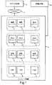
図2は、ストレージ装置4の構成を示すブロック図である。ストレージ装置4は、複数のFMD6と、FMD6に対するデータの入出力を制御するRAIDコントローラ5を備えている。 FIG. 2 is a block diagram showing the configuration of the
各FMD6は、複数のFMチップ8とフラッシュコントローラ7を備えている。FMチップ8は、不揮発性の半導体メモリである。フラッシュコントローラ7は、CPU71とメモリ72を備えており、FMチップ8に対するデータの入出力を制御する。 Each FMD 6 includes a plurality of
RAIDコントローラ5は、CPU51、キャッシュメモリ52、メモリ53、複数のポート54及び不揮発メモリ55を備えている。CPU51は、RAIDコントローラ5全体の動作制御を司るプロセッサであり、不揮発メモリ55に格納された各種プログラムをメモリ53に読み出して実行する。メモリ53は、CPU51により不揮発メモリ55から読み出された各種プログラムを記憶するために用いられるほか、CPU51のワークメモリとしても用いられる。キャッシュメモリ52は、主としてホスト計算機2とFMD6との間で授受されるデータを一時的に格納するために用いられる。各ポート54は、ストレージ装置4をSAN3に接続するためのアダプタである。 The
図3は、FMD6が内部的に記憶領域を管理する方法を概念的に示す。FMD6の各FMチップ8には、複数の物理ブロック81が含まれる。各物理ブロック81は、固定サイズの記憶領域であり、そのサイズは例えば2メガバイトである。フラッシュメモリにおいて、物理ブロックはデータを一括消去する単位の記憶領域である。フラッシュメモリにおけるデータの書き換えは、物理ブロックごとのデータの消去を伴う。フラッシュメモリの特性上、物理ブロックのデータの消去を実行すると、その物理ブロックが劣化する。物理ブロックが劣化すると格納されたデータのエラー発生率が高まり、消去を繰り返すとそのブロックにはデータを格納することができなくなる。このように、物理ブロックの消去回数には限界がある。なお、消去回数の代わりにブロックへのデータの書込み回数を管理してもよい。 FIG. 3 conceptually shows how the FMD 6 manages the storage area internally. Each
また、各物理ブロックには、複数の物理ページが含まれる。各物理ページは、固定サイズの記憶領域であり、そのサイズは例えば8キロバイトである。フラッシュメモリにおいて、物理ページはデータの書込み及び読み出しをする単位の記憶領域である。フラッシュメモリではデータを上書きすることができないという特性があるため、ある物理ページに格納されたデータを更新する場合は、別の物理ページにデータが書込まれる。このため、FMD6内には、更新データを書込むための余剰領域(以下、更新領域)が設けられている。 Each physical block includes a plurality of physical pages. Each physical page is a fixed-size storage area, and the size is, for example, 8 kilobytes. In a flash memory, a physical page is a storage area of a unit for writing and reading data. Since the flash memory has a characteristic that data cannot be overwritten, when updating data stored in one physical page, the data is written in another physical page. For this reason, a surplus area (hereinafter referred to as an update area) for writing update data is provided in the
FMD6のフラッシュコントローラ7は、外部のRAIDコントローラ5に論理記憶空間を提供する。また、フラッシュコントローラ7は、論理記憶空間を所定のサイズ毎に区切って、複数の論理ブロックを管理する。本実施例では、フラッシュコントローラ7は、論理記憶空間を論理ブロック単位で外部に提供するものとする。しかし、フラッシュコントローラ7が外部に提供する論理記憶空間の管理単位は、内部での管理単位である論理ブロック単位とは異なっていてもよい。例えば、フラッシュコントローラ7は、RAIDコントローラ5に512バイト単位で論理記憶空間を提供してもよい。この場合、RAIDコントローラ5は、512バイト単位でアドレスを指定してFMD6にアクセスする。そして、フラッシュコントローラ7は、RAIDコントローラ5が指定するアドレスに対応する論理ブロックを特定し、論理ブロックにマッピングされた物理ブロックにアクセスする。 The
物理ブロック81の状態には、使用中、未使用、使用中止のものがそれぞれある。FMD6は、使用中の物理ブロック81を、その物理ブロック81にマッピングされている論理ブロック82を通して外部に提供する。具体的には、FMD6は、RAIDコントローラ5からリード要求又はライト要求などの入出力要求を受信すると、入出力要求に含まれるパラメタから入出力の対象となる論理ブロック82を求め、その論理ブロック82がマッピングされている物理ブロック81に対してデータの入出力を行う。論理ブロック82と物理ブロック81のマッピングを、メモリ72内のテーブルにより管理する。本実施例では、ブロック単位でのマッピングを説明するが、ページ単位で論理ページと物理ページのマッピングを行ってもよい。なお、未使用のブロックとはデータが消去された状態であり、障害等が発生していない物理ブロックのことであり、更新領域として管理される。つまり、更新領域は、未使用ブロックの集合である。また、使用中止のブロックとは、消去回数が閾値を超えたブロックや、FMチップの物理障害等でデータを格納不能となったブロックである。 The
FMD6のメモリ72は、使用中、未使用、使用中止それぞれの物理ブロック81の数を記憶している。CPU71は、物理ブロック81の状態が変化した場合、メモリ72に記憶されたそれぞれの状態の物理ブロック81の数を更新する。 The
FMD6は、必要に応じて論理ブロック82から物理ブロック81へのマッピングを変更する。例えば、物理ブロック81が予め決められた書込み回数の上限に達した場合、FMD6は、その物理ブロック81のデータを未使用の物理ブロック81にコピーし、元の物理ブロック81にマッピングされていた論理ブロック82のマッピング先をコピー先の物理ブロック81に変更する。その際、FMD6は、元の物理ブロック81を使用中から使用中止に変更し、コピー先の物理ブロック81を未使用から使用中に変更する。 The
図4は、RAIDコントローラ5が内部的に記憶領域を管理する方法を概念的に示す。RAIDコントローラ5は、後述するメモリ53内のテーブルにより、1又は複数のFMD6の記憶領域を1又は複数の仮想ドライブ9として管理する。仮想ドライブ9には、複数の仮想ブロック91が含まれる。本実施例では、各仮想ブロック91は、固定サイズの記憶領域であり、そのサイズは物理ブロック81のサイズと同じであるとする。ただし、各物理ブロック内の1つ以上の物理ページが更新領域として管理されている場合、更新領域を除いたサイズを仮想ブロックのサイズとしてもよい。RAIDコントローラ5は、後述するメモリ53内のテーブルにより、各仮想ブロック91をいずれかの論理ブロック82へマッピングする。一つの仮想ドライブ9の複数の仮想ブロック91が、それぞれ異なるFMD6の論理ブロック82へマッピングされてもよい。 FIG. 4 conceptually shows how the
図5は、RAIDコントローラ5が、仮想ドライブ9を管理するためにメモリ53内に保持するテーブルである仮想ドライブ管理テーブル110の構成例を示す。RAIDコントローラ5は、各仮想ドライブ9について仮想ドライブ管理テーブル110を保持する。仮想ドライブ管理テーブル110には、各仮想ブロック91について、仮想ブロック#111、FMD#112、論理ブロック#113が登録される。 FIG. 5 shows a configuration example of a virtual drive management table 110 that is a table that the
仮想ブロック#111は、仮想ドライブ9内で仮想ブロック91を一意に特定するために利用される番号である。 The
FMD#112は、仮想ブロック#111によって特定される仮想ブロック91がマッピングされている論理ブロック82を含むFMD6を、ストレージ装置4内で一意に特定するために利用される番号である。 The
論理ブロック#113は、仮想ブロック#111によって特定される仮想ブロック91がマッピングされている論理ブロック82を、FMD6内で一意に特定するために利用される番号である。論理ブロック#113は、論理ブロック82の番号の代わりにFMD6が提供する論理アドレス空間内の論理ブロックに対応する論理アドレスの範囲が登録されてもよい。 The
図6は、RAIDコントローラ5がデータの信頼性・可用性を向上させるための処理であるRAID処理を行うために用いるテーブルであるRAIDグループ管理テーブル100の構成例を示す。RAIDグループ管理テーブル100には、RAIDグループ#101、RAIDレベル102、仮想ドライブ#103、FMD#104が登録される。 FIG. 6 shows a configuration example of a RAID group management table 100 that is a table used by the
RAIDグループ#101は、ストレージ装置4内でRAIDグループ10を一意に特定するために利用される番号である。 The
RAIDレベル102は、RAID処理による冗長データの付加方法を識別するために利用される値である。RAIDレベル102には、例えば、「RAID−1」、「RAID−5」、「RAID−6」などがある。RAIDレベル102が「RAID−1」の場合、RAIDコントローラ5は、RAIDグループ10へ格納されたデータを、2つの仮想ドライブ9へミラーリングする。RAIDレベル102が「RAID−5」の場合、RAIDコントローラ5は、RAIDグループへ格納された複数のデータに対して1つのパリティを計算し、各データとそれらに関連するパリティをそれぞれ異なる仮想ドライブ9へ格納する。本実施例では、複数のデータとその複数のデータに基づいて計算されたパリティをあわせてストライプと呼ぶ。RAIDレベル102が「RAID−6」の場合、RAIDコントローラ5は、RAIDグループ10へ格納された複数のデータに対して2つのパリティを計算し、各データとそれらに関連する2つのパリティをそれぞれ異なる仮想ドライブ9へ格納する。 The
仮想ドライブ#103は、RAIDグループ#101によって特定されるRAIDグループ10を構成する仮想ドライブ9を、ストレージ装置4内で特定するために利用される番号である。1つのRAIDグループ#101に対して登録される仮想ドライブ#103の個数は、そのRAIDグループ#101に対して登録されているRAIDレベル102によって異なる。例えば、RAIDレベル102が「RAID−1」の場合、偶数個の仮想ドライブ#103が登録される。RAIDレベル102が「RAID−5」の場合、3個以上の仮想ドライブ#103が登録される。RAIDレベル102が「RAID−6」の場合、4個以上の仮想ドライブ#103が登録される。 The
FMD#104は、仮想ドライブ#103によって特定される仮想ドライブ9の仮想ブロック91がマッピングされ得る論理ブロック82を含むFMD6を、ストレージ装置4内で特定するために利用される番号である。1つのRAIDグループ#101に対して仮想ドライブ#103より多くのFMD#104が登録されてもよい。 The
図7は、RAIDコントローラ5が、ホスト計算機2からリード要求を受信した際に行う処理(ホストリード処理)を説明するフローチャートである。ホストリード処理は、RAIDコントローラ5のCPU51が、プログラムを実行することにより実現される。 FIG. 7 is a flowchart for explaining a process (host read process) performed when the
RAIDコントローラ5は、ホスト計算機2からリード要求を受信すると(SP200)、まず、リード先のFMD6と論理ブロック82を特定する(SP201)。 When the
具体的には、RAIDコントローラ5は、まず、受信したリード要求からリード先の論理ユニットとその論理ユニットの中のリード先の領域を特定するための情報(例えば、アドレス)を抽出し、抽出した情報を基にリード先の仮想ドライブ9と仮想ブロック91を特定する。次に、RAIDコントローラ5は、特定した仮想ドライブ9に対応する仮想ドライブ管理テーブル110を参照し、特定した仮想ブロック91を識別するための番号が仮想ブロック#111として登録されているエントリを特定する。そして、特定したエントリからFMD#112と論理ブロック#113を抽出する。 Specifically, the
次に、RAIDコントローラ5は、ステップSP201で特定したFMD6へ、ステップSP201で特定した論理ブロック82をリードするためのリード要求を送信する(SP202)。 Next, the
次に、RAIDコントローラ5は、ステップSP201で特定したFMD6から、ステップSP202で送信したリード要求の応答を受信する(SP203)。RAIDコントローラ5は、リード要求の応答にリードデータが含まれている場合、リードデータをキャッシュメモリ52へ格納する。 Next, the
次に、RAIDコントローラ5は、ステップSP203で受信した応答がエラー応答か否かを判定する(SP204)。 Next, the
RAIDコントローラ5は、この判定において肯定結果を得ると(SP204:YES)、ステップSP205に進む。肯定結果を得たということは、ステップSP201で特定した論理ブロック82がマッピングされている物理ブロック81が故障したということである。このとき、RAIDコントローラ5は、SP201の処理と同様にリードすることができなかった論理ブロック82のデータと関連する同一ストライプの他のデータとパリティが格納されているFMD6と論理ブロック82を特定し、各FMDから他のデータとパリティを読み出す。そして、RAIDコントローラは、他のデータとパリティを基に、リードすることができなかったデータを再現し、キャッシュメモリ52へ格納する。 If the
次に、RAIDコントローラ5は、後述する新格納先FMD決定処理により、再現したデータの新格納先のFMD6を決定する(SP206)。 Next, the
次に、RAIDコントローラ5は、ステップ206で決定した新格納先のFMD6がステップSP201で特定したリード先のFMD6と同一か否かを判定する(SP207)。 Next, the
RAIDコントローラ5は、この判定において肯定結果を得ると(SP207:YES)、ステップSP208に進む。肯定結果を得たということは、リード先のFMD6に未使用の物理ブロック81が予め決められた閾値より多く残っているということである。このとき、RAIDコントローラ5は、論理ブロック82のマッピング先を未使用の物理ブロック81へ変更することを指示するために、リード先のFMD6へ、REASSIGN BLOCKS要求を送信する。 If the
次に、RAIDコントローラ5は、SP208で送信したREASSIGN BLOCKS要求の応答を受信し(SP209)、ステップSP210に進む。 Next, the
一方、RAIDコントローラ5は、ステップSP207の判定において否定結果を得ると(SP207:NO)、ステップSP213に進む。否定結果を得たということは、ステップSP201で特定したリード先のFMD6とは異なるFMD6へ再現したデータを格納するということである。このとき、RAIDコントローラ5は、ステップSP206で決定した新格納先のFMD6に含まれる論理ブロック82の中から、新格納先の論理ブロック82を決定する。 On the other hand, if the
次に、RAIDコントローラ5は、ステップSP213の決定結果に基づいて仮想ドライブ管理テーブル110を更新する(SP214)。具体的には、RAIDコントローラ5は、ステップSP201で特定した仮想ドライブ9に対応する仮想ドライブ管理テーブル110を参照し、ステップSP201で特定した仮想ブロック91に対応するエントリを特定する。そして、RAIDコントローラ5は、特定したエントリのFMD#112をステップSP206で決定した新格納先のFMD6を特定するための番号に設定し、論理ブロック#113をステップSP213で決定した新格納先の論理ブロック82を特定するための番号に設定する。これにより、FMD内の故障していないブロックを使用し続けることができ、故障ブロックの数が増加してもFMDを閉塞せずに使用し続けることができる。 Next, the
RAIDコントローラ5は、ステップSP214を終えると、ステップSP210に進む。 After finishing step SP214, the
RAIDコントローラ5は、ステップSP210に進むと、ステップSP206で決定した新格納先のFMD6へ、再現したデータをライトするためのライト要求を送信する。 In step SP210, the
次に、RAIDコントローラ5は、ステップSP210で送信したライト要求の応答を受信し(SP211)、ステップSP212に進む。 Next, the
一方、RAIDコントローラ5は、ステップSP204の判定において否定結果を得ると(SP204:NO)、ステップSP212に進む。 On the other hand, if the
RAIDコントローラ5は、ステップSP212に進むと、ホスト計算機2へ、ステップSP200で受信したリード要求に対する応答を送信し(SP212)、ホストリード処理を終了する。 上記ホストリード処理のステップSP210では、RAIDコントローラ5は、ステップSP205で再現したデータを新格納先のFMD6へライトするが、ライトせずにキャッシュメモリ52にダーティデータとして残しておいてもよい。その場合、再現したデータは、後述するデステージ処理により、新格納先のFMD6へライトされる。 When proceeding to step SP212, the
また、上記ホストリード処理のステップSP208では、RAIDコントローラ5は、ステップSP202でリードすることができなかった論理ブロック82のマッピング先を変更するが、変更せずに仮想ブロック91がマッピングされる論理ブロック82を変更してもよい。その場合、RAIDコントローラ5は、リード先のFMD6に含まれる論理ブロック82の中から、新格納先の論理ブロック82を決定する。そして、ステップSP214と同様の手順で仮想ドライブ管理テーブル110を更新する。 In step SP208 of the host read process, the
図8は、RAIDコントローラ5が、ホスト計算機2からライト要求を受信した際に行う処理(ホストライト処理)を説明するフローチャートである。ホストライト処理は、RAIDコントローラ5のCPU51が、プログラムを実行することにより実現される。 FIG. 8 is a flowchart for explaining processing (host write processing) performed when the
RAIDコントローラ5は、ホスト計算機2からライト要求を受信すると(SP300)、まず、ライトデータをキャッシュメモリ52へ格納する(SP301)。 Upon receiving a write request from the host computer 2 (SP300), the
具体的には、RAIDコントローラ5は、まず、受信したライト要求からライト先の論理ユニットとその論理ユニットの中のライト先の領域を特定するための情報を抽出し、抽出した情報を基にライト先のRAIDグループ10とそのRAIDグループ10の中のライト先の仮想ブロックを特定する。そして、RAIDコントローラ5は、ライトデータをキャッシュメモリ52へ格納するとともに、格納したライトデータを管理するための情報をメモリ53内のテーブルに設定する。この情報には、ライト先のRAIDグループ10とそのRAIDグループ10の中のライト先のブロックをそれぞれ特定するための番号が含まれる。 Specifically, the
次に、RAIDコントローラ5は、ライトデータに関連するパリティを計算し、キャッシュメモリ52へ格納する。パリティを計算する方法には様々なものがあるが、例えば、RAID−5の場合、計算するパリティに関連するストライプのすべてのデータの排他的論理和を計算するという方法がある。 Next, the
次に、RAIDコントローラ5は、後述するデステージ処理により、ライトデータとパリティをFMD6へ書き込む(SP303)。 Next, the
最後に、RAIDコントローラ5は、ホスト計算機2へ、ステップSP300で受信したライト要求に対する応答を送信し(SP304)、ホストライト処理を終了する。 Finally, the
上記ホストライト処理では、RAIDコントローラ5は、ホスト計算機2へライト要求に対する応答を返す前にライトデータをFMD6へ書き込むが(ライトスルー)、ライトデータをFMD6へ書き込まずにホスト計算機2へ応答を返してもよい(ライトバック)。その場合、RAIDコントローラ5は、ライトデータをFMD6へ書き込まずにキャッシュメモリ52にダーティデータとして残し、後述するデステージ処理でFMD6へ書き込む。 In the above host write process, the
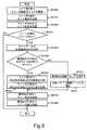
図9は、RAIDコントローラ5が、キャッシュメモリ52に格納されているデータまたはパリティを、FMD6にデステージする際に行う処理(デステージ処理)を説明するフローチャートである。デステージ処理は、RAIDコントローラ5のCPU51が、プログラムを実行することにより実現される。 FIG. 9 is a flowchart for explaining processing (destage processing) performed when the
RAIDコントローラ5は、ライト要求をライトスルーで処理する場合、ライト要求に対する応答を送信する前にデステージ処理を実行する。一方、RAIDコントローラ5は、ライト要求をライトバックで処理する場合、ライト要求とは非同期に、定期的にデステージ処理を実行する。 The
デステージ処理では、RAIDコントローラ5は、まず、ライト先のFMD6と論理ブロック82を特定する(SP400)。具体的には、RAIDコントローラ5は、まず、キャッシュメモリ52へ格納したライトデータを管理するためのメモリ53内のテーブルを参照し、デステージするデータのライト先のRAIDグループ10とそのRAIDグループ10の中のライト先のブロックをそれぞれ特定する。次に、RAIDコントローラ5は、その情報を基にライト先の仮想ドライブ9と仮想ブロック91を特定する。次に、RAIDコントローラ5は、特定した仮想ドライブ9と仮想ブロック91に対応するFMD6と論理ブロック82を特定する。具体的には、RAIDコントローラ5は、特定した仮想ドライブ9に対応する仮想ドライブ管理テーブル110を参照し、特定した仮想ブロック91を識別するための番号が仮想ブロック#111として登録されているFMD#112と論理ブロック#113を抽出する。 In the destage processing, the
次に、RAIDコントローラ5は、SP400で特定したFMD6へ、デステージするデータまたはパリティをSP400で特定した論理ブロック82へライトするためのライト要求を送信する(SP401)。 Next, the
次に、RAIDコントローラ5は、SP400で特定したFMD6から、SP401で送信したライト要求の応答を受信する(SP402)。 Next, the
次に、RAIDコントローラ5は、ライト要求の応答がエラー応答か否かを判定する(SP403)。 Next, the
RAIDコントローラ5は、この判定において肯定結果を得ると(SP403:YES)、ステップSP404に進む。肯定結果を得たということは、ステップSP400で特定した論理ブロック82にマッピングされている物理ブロック81が故障したということである。このとき、RAIDコントローラ5は、後述する新格納先FMD決定処理により、デステージするデータの新格納先のFMD6を決定する。 If the
次に、RAIDコントローラ5は、ステップSP404で決定したライト先のFMD6がステップSP400で特定したライト先のFMD6と同一か否かを決定する(SP405)。 Next, the
RAIDコントローラ5は、この判定において肯定結果を得ると(SP405:YES)、ステップSP406に進む。肯定結果を得たということは、ライト先のFMD6に未使用の物理ブロック81が予め決められた閾値より多く残っているということである。このとき、RAIDコントローラ5は、論理ブロック82のマッピング先を未使用の物理ブロック81へ変更することを指示するために、ライト先のFMD6へ、REASSIGN BLOCKS要求を送信する。 If the
次に、RAIDコントローラ5は、SP406で送信したREASSIGN BLOCKS要求の応答を受信し(SP407)、ステップSP408に進む。 Next, the
一方、RAIDコントローラ5は、ステップSP405の判定において否定結果を得ると(SP405:NO)、ステップSP410に進む。否定結果を得たということは、ステップSP400で特定したライト先のFMD6とは異なるFMD6へデステージするデータを格納するということである。このとき、RAIDコントローラ5は、ステップSP404で決定した新格納先のFMD6に含まれる論理ブロック82の中から、新格納先の論理ブロック82を決定する。また、RAIDコントローラ5は、ステップSP400で特定したライト先のFMD6からデータを格納可能な物理記憶領域の残容量を取得し、残物理容量が閾値より小さい場合、ステップSP400で特定した論理ブロック82を使用不能な論理ブロックとして管理する。例えば、残物理容量が論理記憶領域の容量より小さい場合、FMD6は、RAIDコントローラ5からデータを受領してもそのデータをフラッシュメモリに格納することができないため、RIADコントローラにエラー応答を送信することになる。このため、予め論理ブロックを使用不能として管理することで、RAIDコントローラ5とFMD6間の不要な通信オーバーヘッドを削減することができる。 On the other hand, if the
次に、RAIDコントローラ5は、ステップSP410の決定結果に基づいて仮想ドライブ管理テーブル110を更新する(SP411)。具体的には、RAIDコントローラ5は、ステップSP400で特定した仮想ドライブ9に対応する仮想ドライブ管理テーブル110を参照し、ステップ400で特定した仮想ブロック91に対応するエントリを特定する。そして、RAIDコントローラ5は、特定したエントリのFMD#112をステップSP404で決定した新格納先のFMD6を特定するための番号に設定し、論理ブロック#113をステップSP410で決定した新格納先の論理ブロック82を特定するための番号に設定する。これにより、FMD内の故障していないブロックを使用し続けることができ、故障ブロックの数が増加してもFMDを閉塞せずに使用し続けることができる。 Next, the
RAIDコントローラ5は、ステップSP411を終えると、ステップSP408に進む。 After completing step SP411, the
RAIDコントローラ5は、ステップSP408に進むと、ステップSP404で決定した新格納先のFMD6へ、デステージするデータをライトするためのライト要求を送信する。 In step SP408, the
次に、RAIDコントローラ5は、SP405で決定したFMD6から、SP408で送信したライト要求の応答を受信し(SP409)、デステージ処理を終了する。 Next, the
一方、ステップSP403の判定において否定結果を得ると(SP403:NO)、RAIDコントローラ5は、デステージ処理を終了する。 On the other hand, if a negative result is obtained in the determination at step SP403 (SP403: NO), the
上記デステージ処理のステップSP406では、RAIDコントローラ5は、ステップSP401でライトすることができなかった論理ブロック82のマッピング先を変更するが、変更せずに仮想ブロック91がマッピングされる論理ブロック82を変更してもよい。その場合、RAIDコントローラ5は、ライト先のFMD6に含まれる論理ブロック82の中から、新格納先の論理ブロック82を決定する。そして、ステップSP411と同様の手順で仮想ドライブ管理テーブル110を更新する。 In step SP406 of the destage processing, the
図10は、RAIDコントローラ5が、ストレージ装置4内の各FMD6の未使用の物理ブロック81の割合を平準化するために定期的に行う処理(未使用ブロック平準化処理)を説明するフローチャートである。未使用ブロック平準化処理は、RAIDコントローラ5のCPU51が、プログラムを実行することにより実現される。FMD間で未使用の物理ブロックの数に偏りがあると、FMD間で性能にばらつきが生じる。つまり、使用中の物理ブロックの数が多いFMDにアクセスが集中することになり、特定のFMDの性能が低下する。未使用ブロック平準化処理により、このようなFMD間の性能のばらつきを平準化することができる。また、未使用ブロック平準化処理により、予め未使用のブロック数を平準化しておくことができる。これにより、ホストリード/ライト処理に伴って別FMDへデータのコピーを行わなければならなくなる確率を下げることができ、ホスト計算機からのリード/ライト要求に対する応答遅延を回避することができる。 FIG. 10 is a flowchart for explaining a process (unused block leveling process) performed periodically by the
未使用ブロック平準化処理では、RAIDコントローラ5は、まず、ストレージ装置4内のFMD6を一つ選択する(SP500)。 In the unused block leveling process, the
次に、RAIDコントローラ5は、ステップSP500で選択したFMD6の未使用の物理ブロック81の数が閾値未満か否かを判定する(SP501)。具体的には、RAIDコントローラ5は、ステップSP500で選択したFMD6へ未使用の物理ブロック81の数に関する問合せを行い、FMD6から未使用のブロック81の数を取得し、未使用のブロック81の数が予め決められた閾値未満か否かを判定する。FMD6がRAIDコントローラ5から問合せを受けると、FMD6のCPU71は、メモリ72から未使用の物理ブロック81の数を読み出し、RAIDコントローラ5へ送信する。 Next, the
RAIDコントローラ5は、この判定において肯定結果を得ると(SP501:YES)、ステップSP502に進む。そして、ステップSP500で選択したFMD6に含まれる論理ブロック82の中から、移動元の論理ブロック81を一つ選択する。 If the
次に、RAIDコントローラ5は、後述する新格納先FMD決定処理により、移動先のFMD6を決定する(SP503)。 Next, the
次に、RAIDコントローラ5は、ステップSP503で決定した移動先のFMD6に含まれる論理ブロック82の中から、移動先の論理ブロック82を決定する(SP504)。 Next, the
次に、RAIDコントローラ5は、ステップSP502で選択した移動元の論理ブロック81のデータを、ステップSP504で決定した移動先の論理ブロック82へコピーする(SP505)。 Next, the
次に、RAIDコントローラ5は、仮想ドライブ管理テーブル110を更新する(SP506)。具体的には、RAIDコントローラ5は、移動元の論理ブロック82にマッピングされている仮想ブロック91を含む仮想ドライブ9に対応する仮想ドライブ管理テーブル110を参照し、移動元の論理ブロック82にマッピングされている仮想ブロック91に対応するエントリを特定する。そして、RAIDコントローラ5は、特定したエントリのFMD#112を移動先のFMD6を特定するための番号に設定し、論理ブロック#113を移動先の論理ブロック82を特定するための番号に設定する。 Next, the
RAIDコントローラ5は、ステップSP506を終えると、ステップSP507に進む。 After completing step SP506, the
一方、RAIDコントローラ5は、ステップSP501の判定において否定結果を得ると(SP501:NO)、ステップSP507に進む。 On the other hand, if the
RAIDコントローラ5は、ステップSP507に進むと、ストレージ装置4内のFMD6をすべて選択したか否を判定する。 When proceeding to step SP507, the
RAIDコントローラ5は、この判定において肯定結果を得ると(SP507:YES)、未使用ブロック平準化処理を終了する。 If the
一方、RAIDコントローラ5は、ステップSP507の判定において否定結果を得ると(SP507:NO)、ステップSP500に進む。 On the other hand, if the
上記未使用ブロック平準化処理では、RAIDコントローラ5が主体となって未使用の物理ブロック81の数が閾値未満のFMD6を探すが、FMD6が主体となって未使用の物理ブロック81の数が閾値未満の場合にRAIDコントローラ5に通知してもよい。その場合、RAIDコントローラ5は、FMD6から通知を受信すると、ステップSP502からステップSP506を行う。FMD6は、FMチップの故障を検出したことを契機に、未使用の物理ブロックの数をチェックし、RAIDコントローラ5に対して障害が発生したことを示す情報を通知してもよい。FMチップが故障すると、使用可能な物理ブロックの数が大幅に減少するため、FMD間の未使用物理ブロック数のばらつきも大きくなる。このため、FMD6がFMチップの障害を検出したタイミングでRAIDコントローラ5に通知することで、RAIDコントローラ5は、早期に未使用ブロック平準化処理を実行することができる。なお、FMチップの障害とは、例えばFMチップ上の制御回路や配線の物理的な障害である。FMチップ上の制御回路に障害が発生すると、そのFMチップ上の物理ブロックにデータのリード/ライトができなくなるため、すべての物理ブロックが使用不可となる。 In the unused block leveling process, the
図11は、RAIDコントローラ5が、仮想ブロック91のマッピング先の論理ブロック82を変更する際、マッピング変更先のFMD6を決定するために行う処理(新格納先FMD決定処理)を説明するフローチャートである。新格納先FMD決定処理は、RAIDコントローラ5のCPU51が、プログラムを実行することにより実現される。 FIG. 11 is a flowchart for explaining processing (new storage destination FMD determination processing) performed when the
新格納先FMD決定処理では、RAIDコントローラ5は、まず、マッピング変更先の候補のFMD6を一つ選択する(SP600)。具体的には、RAIDコントローラ5は、まず、RAIDグループ管理テーブル100を参照し、マッピング先を変更する仮想ブロック91を含む仮想ドライブ9が登録されているエントリを特定する。そして、RAIDコントローラ5は、特定したエントリのFMD#104に登録されている番号の中から、番号を一つ選択する。 In the new storage destination FMD determination process, the
次に、RAIDコントローラ5は、ステップSP600で選択したFMD6の未使用の物理ブロック81の数が閾値以上か否かを判定する(SP601)。具体的には、RAIDコントローラ5は、ステップSP600で選択したFMD6へ未使用の物理ブロック81の数に関する問合せを行い、FMD6から未使用のブロック81の数を取得し、未使用のブロック81の数が予め決められた閾値未満か否かを判定する。FMD6がRAIDコントローラ5から問合せを受けると、FMD6のCPU71は、メモリ72から未使用の物理ブロック81の数を読み出し、RAIDコントローラ5へ送信する。未使用の物理ブロック数が閾値未満の場合、そのFMDにデータを格納することができないか、格納できたとしてもすぐに未使用の物理ブロック数が少ない状態となり未使用ブロック数の平準化が必要となる可能性が高い。このため、未使用の物理ブロック数が閾値以上のFMDを新格納先FMDとして選択するためにSP601の判定を行う。 Next, the
RAIDコントローラ5は、この判定において肯定結果を得ると(SP601:YES)、ステップSP602に進む。そして、RAIDコントローラ5は、マッピング変更対象のデータと同一ストライプの他のデータまたはパリティがステップSP600で選択したFMD6に存在するか否かを判定する。同一ストライプの複数のデータ及びパリティの2つ以上が同じFMDに格納されると、冗長性が低下する。SP602の判定により、新格納先FMDとして冗長性が低下するFMDを選択することを回避することができる。 If the
RAIDコントローラ5は、この判定において肯定結果を得ると(SP602:YES)、ステップSP603に進む。そして、RAIDコントローラ5は、マッピング変更先の候補のFMD6をすべて選択したか否かを判定する。具体的には、RAIDコントローラ5は、ステップSP600で特定したエントリのFMD#104に登録されている番号をすべて選択したか否かを判定する。 If the
RAIDコントローラ5は、この判定において肯定結果を得ると(SP603:YES)、ステップSP604に進み、新格納先として適切なFMD6がないと判断する。この場合、新格納先FMD決定処理を呼び出したホストリード処理、デステージ処理または未使用ブロック平準化処理は失敗する。ここで、RAIDコントローラ5は、ホスト計算機2やストレージ装置4の管理計算機20にFMDの増設を促す警告を通知する。これにより、管理者はFMD6を増設すべき契機を知ることができる。 If the
RAIDコントローラ5は、ステップSP604を終えると、新格納先FMD決定処理を終了する。 After completing step SP604, the
一方、RAIDコントローラ5は、ステップSP601の判定において否定結果を得ると(SP601:NO)、ステップSP603に進む。 On the other hand, if the
一方、RAIDコントローラ5は、ステップSP602の判定において否定結果を得ると(SP602:NO)、ステップSP605に進み、マッピング変更先のFMD6をステップSP600で選択したFMD6に決定する。 On the other hand, if the
一方、RAIDコントローラ5は、ステップSP603の判定において否定結果を得ると(SP603:NO)、ステップSP600に進む。 On the other hand, if the
このように、RAIDコントローラ5とFMD6が連携して情報をやり取りすることで、新格納先FMD決定処理が行われる。この新格納先FMD決定処理により、FMDの故障していない物理ブロックを活用するために他の適切なFMDを選択することができる。 As described above, the
実施例1では、論理ユニットに、複数の仮想ドライブに基づくRAIDグループの記憶領域を、固定的に対応付ける構成について説明した。本実施例では、いわゆるシンプロビジョニング(Thin Provisioning)技術を用いて作成される仮想的な論理ユニットに、複数の仮想ドライブに基づくRAIDグループの記憶領域を動的に割り当てる構成を説明する。 In the first embodiment, the configuration has been described in which a storage area of a RAID group based on a plurality of virtual drives is fixedly associated with a logical unit. In this embodiment, a configuration in which a storage area of a RAID group based on a plurality of virtual drives is dynamically allocated to a virtual logical unit created using a so-called thin provisioning technique will be described.
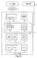
図12は、本実施例の概要を示す図である。実施例1と共通する部分は説明を省略する。 FIG. 12 is a diagram showing an outline of the present embodiment. Description of the parts common to the first embodiment is omitted.
シンプロビジョニング技術により作成される仮想的な論理ユニット(以下、仮想論理ユニット23と呼ぶ)は、初期状態では仮想論理ユニット23の各領域に特定の記憶領域が割り当てられていない。RAIDコントローラ5は、ホスト計算機2から仮想論理ユニット23上の位置(LBA)を指定したライト要求を受信すると、当該位置に記憶領域が割り当てられているか確認し、割り当てられていない場合、その位置に記憶領域を割り当てる。 In a virtual logical unit (hereinafter referred to as virtual logical unit 23) created by the thin provisioning technology, a specific storage area is not allocated to each area of the virtual
なお、RAIDコントローラ5は、仮想論理ユニット23上の記憶空間を複数の固定サイズ領域に分割して管理しており、この固定サイズ領域は「仮想チャンク24」と呼ばれる。実施例2においては、一例として、1つの仮想チャンクのサイズは1ストライプのサイズと等しいものとする。 The
また、ストレージ装置4においては、仮想論理ユニット23の仮想チャンクに対して割り当てることができるRAIDグループ10の記憶領域を管理するために、プール21という概念を定義している。RAIDコントローラ5は、プール21内のRAIDグループ10の記憶領域を複数の固定サイズ領域に分割して管理しており、このプール21内の固定サイズ領域は「チャンク22」と呼ばれる。実施例2においては、一例として、1つのチャンクは1つのストライプを含むものとする。 In the
RAIDコントローラ5は、ホスト計算機2からのライト要求に応じて、仮想論理ユニット23に記憶領域を割り当てる際、プール21内に存在する複数のチャンクから少なくとも1つを選択して割り当てる。 The
図13は、RAIDコントローラ5が記憶領域の管理に用いるプール管理テーブル130の構成例を示す。プール管理テーブル130には、プール#131、RAIDグループ#132、RAIDレベル133、チャンク#134、割当状態135、仮想ドライブ#136、FMD#137が登録される。なお、プール#131、チャンク#134及び割当状態135以外の項目は図6と同様のため、以下では説明を省略する。 FIG. 13 shows a configuration example of the pool management table 130 used by the
プール#131は、ストレージ装置4内でプールを一意に特定するために利用される番号である。図13に示す通り、1つのプールは1つ以上のRAIDグループを含む。
チャンク#134は、プール21内でチャンクを一意に特定するために利用される番号である。各RAIDグループは複数のチャンクを含む。また、各チャンク22はRAIDグループを構成する複数の仮想ドライブにまたがって定義される。 The
割当状態135は、各チャンク22が仮想論理ユニット23に割当済みであるか、未割当であるかを示す。RAIDコントローラ5は、仮想論理ユニット23へのライト要求を受領すると、未割当のチャンク22を選択して仮想論理ユニット23に割り当てる。 The
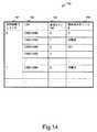
図14は、RAIDコントローラ5が仮想論理ユニットに割り当てられた記憶領域の管理に用いる仮想論理ユニット管理テーブル140の構成例を示す。仮想論理ユニット管理テーブル140には、仮想論理ユニット#141、LBA(Logical Block Address)142、仮想チャンク#143、割当済みチャンク#144が登録される。 FIG. 14 shows a configuration example of the virtual logical unit management table 140 used by the
仮想論理ユニット#141は、ストレージ装置4内で仮想論理ユニット23を一意に特定するために利用される番号である。ストレージ装置4は、1つ以上の仮想論理ユニット23を含む。 The virtual
LBA142は、仮想論理ユニット23上の位置を特定するための値である。ホスト計算機2は、仮想論理ユニット23のLBA142を指定してライト要求やリード要求を送信する。 The
仮想チャンク#143は、仮想論理ユニット23内で仮想チャンク24を一意に特定するために利用される番号である。RAIDコントローラ5は、仮想論理ユニット23上のLBAを所定のLBAの範囲ごとに分割して、仮想チャンク24として管理する。 The
割当済みチャンク#144は、仮想チャンク24に割り当てられているチャンク22の番号を示す。また、割当済みチャンク#144が「未割当」の場合は、当該仮想チャンク24にチャンク22が割り当てられていないことを示している。 Allocated
例えば、RAIDコントローラ5は、ホスト計算機2から、仮想論理ユニット#141が「0」でありLBA142が「1000−1999」の範囲内を指定するライト要求を受信した場合、当該LBA範囲に対応する仮想チャンク24にはチャンク22が割り当てられていないため、プール管理テーブル130を参照して未割当のチャンク22を割り当てる。また、RAIDコントローラ5は、プール管理テーブル130に基づいて、ライト先のチャンク22からライト先のRAIDグループ10を特定することができる。 For example, when the
ライト処理及びリード処理については、チャンク22からRAIDグループの対応関係を特定する以外の処理は実施例1と同様であるため説明を省略する。 The write process and the read process are the same as those in the first embodiment except for specifying the correspondence relationship of the RAID group from the
未使用ブロック平準化処理(図10)は、実施例1と同様であるため説明を省略する。 Since the unused block leveling process (FIG. 10) is the same as that of the first embodiment, the description thereof is omitted.
新格納先FMD決定処理(図11)のSP604において、新格納先として適切なFMD6がないと判断された場合も、RAIDコントローラ5は、管理計算機20にFMD6の増設を促す警告を通知することができる。また、新格納先として適切なFMD6が存在する場合であっても、プールの容量が所定値以下となったら、RAIDコントローラ5は管理計算機20にプール容量の減少を通知しても良い。なお、プールの容量とは、プール内のFMD6がデータを格納可能な容量の合計である。新格納先FMD6が存在しない場合は、ライト処理及びリード処理は失敗することになる。RAIDコントローラ5は、プールの容量が所定値以下となったことを契機に管理計算機20に通知することで、FMD6の容量が枯渇する前に管理者は早期にFMD6の増設を行うことができる。 In the SP 604 of the new storage destination FMD determination process (FIG. 11), even when it is determined that there is no
よって、シンプロビジョニングによる仮想論理ユニットに複数の仮想ドライブに基づくRAIDグループから記憶領域を割り当てる構成であっても、FMD内の一部のブロックが故障した場合に、故障していないブロックを有効活用し、FMDを使用できる期間を引き延ばすことができる。 Therefore, even when a storage area is allocated from a RAID group based on a plurality of virtual drives to a virtual logical unit by thin provisioning, if some blocks in the FMD fail, the blocks that have not failed are effectively used. , The period during which the FMD can be used can be extended.
4:ストレージ装置
6:FMD(フラッシュメモリデバイス)4: Storage device 6: FMD (flash memory device)
Claims (6)
Translated fromJapanese前記複数のフラッシュメモリデバイスのそれぞれは、複数のデータ消去単位である物理ブロックをそれぞれに有する複数のフラッシュメモリチップと、前記複数の物理ブロックの1つ以上に論理記憶領域を対応付けて論理記憶領域を提供するフラッシュコントローラと、を有し、
前記RAIDコントローラは、それぞれが、前記複数のフラッシュメモリデバイスのそれぞれによって提供される前記論理記憶領域の一部を含む複数の仮想ドライブを管理し、前記複数の仮想ドライブをRAIDグループとして制御し、
前記複数のフラッシュメモリデバイスのうちの第1フラッシュメモリデバイスの第1フラッシュコントローラは、前記複数の物理ブロックのうち1つ以上の物理ブロックの障害を検出した場合、前記RAIDコントローラにエラー情報を通知し、
前記RAIDコントローラは、
前記エラー情報を受信すると、故障した物理ブロックに対応付けられている第1論理記憶領域を特定し、
前記第1論理記憶領域のデータを、前記データに関連するデータとパリティとに基づいて復元し、
前記第1論理記憶領域に対応付けられている第1仮想ドライブの第1仮想記憶領域を特定し、
前記第1仮想ドライブに対応付けられているフラッシュメモリデバイスから障害が発生していないデータを格納可能な状態の物理ブロックの数である未使用ブロック数を取得し、前記未使用ブロック数が第1閾値以上であるフラッシュメモリデバイスを選択し、
前記選択したフラッシュメモリデバイスが前記第1フラッシュメモリデバイスである場合、前記第1フラッシュメモリデバイスに対して、前記第1論理記憶領域のマッピング先を未使用の物理ブロックへ変更することを指示し、復元した前記第1論理記憶領域のデータを、前記第1論理記憶領域を指定して前記第1フラッシュメモリデバイスにライトし、
前記選択したフラッシュメモリデバイスが前記第1フラッシュメモリデバイスと異なる第2フラッシュメモリデバイスである場合、前記第1仮想記憶領域と前記第1論理記憶領域との対応関係を、前記第1仮想記憶領域と前記第2フラッシュメモリデバイスの第2論理記憶領域との関係に変更し、復元した前記第1論理記憶領域のデータを、前記第2論理記憶領域を指定して前記第2フラッシュメモリデバイスにライトし、
前記RAIDコントローラは、さらに、未使用ブロック平準化処理を実行し、
前記RAIDコントローラは、前記未使用ブロック平準化処理において、
前記第1仮想ドライブに対応付けられているフラッシュメモリデバイスから未使用ブロック数を取得し、前記未使用ブロック数が第2閾値未満であるフラッシュメモリデバイスを選択し、
前記未使用ブロック数が第2閾値未満であるフラッシュメモリデバイスに含まれる論理記憶領域から移動元論理記憶領域を選択し、
前記第1仮想ドライブに対応付けられているフラッシュメモリデバイスから、未使用ブロック数が前記第1閾値以上であるフラッシュメモリデバイスを選択し、
前記未使用ブロック数が前記第1閾値以上であるフラッシュメモリデバイスに含まれる論理記憶領域から移動先論理記憶領域を選択し、
前記移動元論理記憶領域のデータを、前記移動先論理記憶領域にコピーし、
前記移動元論理記憶領域にマッピングされている仮想記憶領域を前記移動先論理記憶領域にマッピングする
ストレージ装置。A plurality of flash memory devices and a RAID controller;
Each of the plurality of flash memory devices includes a plurality of flash memory chips each having a plurality of physical blocks that are a plurality of data erasing units, and a logical storage area associated with one or more of the plurality of physical blocks. Providing a flash controller, and
The RAID controller manages a plurality of virtual drives each including a part of the logical storage area provided by each of the plurality of flash memory devices, and controls the plurality of virtual drives as a RAID group;
When the first flash controller of the first flash memory device of the plurality of flash memory devices detects a failure of one or more physical blocks of the plurality of physical blocks, the first flash controller notifies the RAID controller of error information. ,
The RAID controller is
Upon receiving the error information, the first logical storage area associated with the failed physical block is identified,
Restoring the data in the first logical storage area based on the data and parity associated with the data;
Identifying a first virtual storage area of a first virtual drive associated with the first logical storage area;
The number of unused blocks, which is the number of physical blocks in a state where data that has not failed can be stored, is obtained from the flash memory device associated with the first virtual drive, and the number of unused blocks is first. Select the flash memory device that is above the threshold,
If the selected flash memory device is the first flash memory device, instructing the first flash memory device to change the mapping destination of the first logical storage area to an unused physical block; Writing the restored data of the first logical storage area to the first flash memory device by designating the first logical storage area;
When the selected flash memory device is a second flash memory device different from the first flash memory device, a correspondence relationship between the first virtual storage area and the first logical storage area is expressed as the first virtual storage area. The data of the first logical storage area is changed to a relationship with the second logical storage area of the second flash memory device and the restored data is written to the second flash memory device by designating the second logical storage area. ,
The RAID controller further executes unused block leveling processing,
The RAID controller, in the unused block leveling process,
Obtaining an unused block number from a flash memory device associated with the first virtual drive, selecting a flash memory device having the unused block number less than a second threshold;
Selecting a source logicalstorage area from logicalstorage areas included in a flash memory device in which the number of unused blocks is less than a second threshold;
From the flash memory devices associated with the first virtual drive, select a flash memory device whose number of unused blocks is equal to or greater than the first threshold;
Selecting a migration destination logicalstorage area from logicalstorage areas included in a flash memory device in which the number of unused blocks is equal to or greater than the first threshold;
Copy the data in the source logicalstorage area to the destination logicalstorage area ,
A storage apparatus that maps a virtualstorage area mapped to the migration source logicalstorage area to the migration destination logicalstorage area .
請求項1記載のストレージ装置。The storage apparatus according to claim 1, wherein the failure is a state where the number of times of erasing a certainphysical block is equal to or greater than a predetermined value or a state where a failure occurs in a flash memory chip including a certainphysical block.
請求項2記載のストレージ装置。The first flash controller receives an access request from the RAID controller, and notifies the error information to the RAID controller when a failure has occurred in a physical block targeted for the access request. Storage device.
請求項3記載のストレージ装置。The storage apparatus according to claim 3, wherein the first flash controller notifies the error information to the RAID controller when detecting that a failure has occurred in at least one of the plurality of flash memory chips.
請求項2記載のストレージ装置。The storage apparatus according to claim 2, wherein the RAID controller provides a host computer with a logical unit based on a RAID group composed of the plurality of virtual drives.
請求項1記載のストレージ装置。The RAID controller provides a virtual logical unit to a host computer, divides a storage area of a RAID group composed of the plurality of virtual drives into a plurality of chunks, and issues a write request from the host computer to the virtual logical unit. The storage apparatus according to claim 1, wherein upon receipt, the chunk is allocated to the virtual logical unit.
Applications Claiming Priority (1)
| Application Number | Priority Date | Filing Date | Title |
|---|---|---|---|
| PCT/JP2014/051889WO2015114744A1 (en) | 2014-01-29 | 2014-01-29 | Storage device |
Publications (2)
| Publication Number | Publication Date |
|---|---|
| JPWO2015114744A1 JPWO2015114744A1 (en) | 2017-03-23 |
| JP6279620B2true JP6279620B2 (en) | 2018-02-14 |
Family
ID=53756363
Family Applications (1)
| Application Number | Title | Priority Date | Filing Date |
|---|---|---|---|
| JP2015559650AExpired - Fee RelatedJP6279620B2 (en) | 2014-01-29 | 2014-01-29 | Storage device |
Country Status (3)
| Country | Link |
|---|---|
| US (1) | US9946616B2 (en) |
| JP (1) | JP6279620B2 (en) |
| WO (1) | WO2015114744A1 (en) |
Families Citing this family (24)
| Publication number | Priority date | Publication date | Assignee | Title |
|---|---|---|---|---|
| US9921910B2 (en)* | 2015-02-19 | 2018-03-20 | Netapp, Inc. | Virtual chunk service based data recovery in a distributed data storage system |
| US10810374B2 (en)* | 2016-08-03 | 2020-10-20 | Baidu Usa Llc | Matching a query to a set of sentences using a multidimensional relevancy determination |
| KR102795652B1 (en)* | 2016-08-19 | 2025-04-15 | 에스케이하이닉스 주식회사 | Memory system and operating method for the same |
| JP6817340B2 (en)* | 2017-02-06 | 2021-01-20 | 株式会社日立製作所 | calculator |
| US10761743B1 (en) | 2017-07-17 | 2020-09-01 | EMC IP Holding Company LLC | Establishing data reliability groups within a geographically distributed data storage environment |
| JP7153435B2 (en)* | 2017-10-12 | 2022-10-14 | ラピスセミコンダクタ株式会社 | Data rewriting method for non-volatile memory and semiconductor device |
| US10496330B1 (en)* | 2017-10-31 | 2019-12-03 | Pure Storage, Inc. | Using flash storage devices with different sized erase blocks |
| US10929034B2 (en) | 2018-05-08 | 2021-02-23 | International Business Machines Corporation | Allocation of task control blocks in a storage controller for staging and destaging based on storage rank response time |
| US11436203B2 (en) | 2018-11-02 | 2022-09-06 | EMC IP Holding Company LLC | Scaling out geographically diverse storage |
| US11204716B2 (en)* | 2019-01-31 | 2021-12-21 | EMC IP Holding Company LLC | Compression offloading to RAID array storage enclosure |
| US10831407B2 (en)* | 2019-01-31 | 2020-11-10 | EMC IP Holding Company LLC | Write flow offloading to raid array storage enclosure |
| US11055188B2 (en)* | 2019-04-12 | 2021-07-06 | EMC IP Holding Company LLC | Offloading error processing to raid array storage enclosure |
| US11748004B2 (en) | 2019-05-03 | 2023-09-05 | EMC IP Holding Company LLC | Data replication using active and passive data storage modes |
| US11449399B2 (en) | 2019-07-30 | 2022-09-20 | EMC IP Holding Company LLC | Mitigating real node failure of a doubly mapped redundant array of independent nodes |
| US11449248B2 (en) | 2019-09-26 | 2022-09-20 | EMC IP Holding Company LLC | Mapped redundant array of independent data storage regions |
| US11435910B2 (en) | 2019-10-31 | 2022-09-06 | EMC IP Holding Company LLC | Heterogeneous mapped redundant array of independent nodes for data storage |
| US11435957B2 (en) | 2019-11-27 | 2022-09-06 | EMC IP Holding Company LLC | Selective instantiation of a storage service for a doubly mapped redundant array of independent nodes |
| US11507308B2 (en) | 2020-03-30 | 2022-11-22 | EMC IP Holding Company LLC | Disk access event control for mapped nodes supported by a real cluster storage system |
| US11693983B2 (en) | 2020-10-28 | 2023-07-04 | EMC IP Holding Company LLC | Data protection via commutative erasure coding in a geographically diverse data storage system |
| US11847141B2 (en) | 2021-01-19 | 2023-12-19 | EMC IP Holding Company LLC | Mapped redundant array of independent nodes employing mapped reliability groups for data storage |
| US11625174B2 (en)* | 2021-01-20 | 2023-04-11 | EMC IP Holding Company LLC | Parity allocation for a virtual redundant array of independent disks |
| US11449234B1 (en) | 2021-05-28 | 2022-09-20 | EMC IP Holding Company LLC | Efficient data access operations via a mapping layer instance for a doubly mapped redundant array of independent nodes |
| US11354191B1 (en) | 2021-05-28 | 2022-06-07 | EMC IP Holding Company LLC | Erasure coding in a large geographically diverse data storage system |
| US12204445B2 (en)* | 2021-11-12 | 2025-01-21 | Samsung Electronics Co., Ltd. | Method of operating a storage device using multi-level address translation and a storage device performing the same |
Family Cites Families (18)
| Publication number | Priority date | Publication date | Assignee | Title |
|---|---|---|---|---|
| US6327674B1 (en) | 1997-12-09 | 2001-12-04 | Kabushiki Kaisha Toshiba | Digital information recording and reproducing system and defect managing system applied to the same |
| JPH11176105A (en)* | 1997-12-11 | 1999-07-02 | Toshiba Corp | Digital information recording / reproducing system and defect management method applied to the system |
| JP4439096B2 (en) | 2000-08-28 | 2010-03-24 | 株式会社東芝 | Memory card and address conversion method applied to the card |
| JP4818812B2 (en) | 2006-05-31 | 2011-11-16 | 株式会社日立製作所 | Flash memory storage system |
| US20050193273A1 (en)* | 2004-02-18 | 2005-09-01 | Xiotech Corporation | Method, apparatus and program storage device that provide virtual space to handle storage device failures in a storage system |
| JP4757165B2 (en)* | 2006-10-04 | 2011-08-24 | 株式会社日立製作所 | Computer system, data migration monitoring method, and data migration monitoring program |
| US8019938B2 (en)* | 2006-12-06 | 2011-09-13 | Fusion-I0, Inc. | Apparatus, system, and method for solid-state storage as cache for high-capacity, non-volatile storage |
| US8037266B2 (en) | 2007-01-02 | 2011-10-11 | Sandisk Il Ltd. | Apparatus and method for archiving digital content |
| US20090271564A1 (en)* | 2008-04-25 | 2009-10-29 | Hitachi, Ltd. | Storage system |
| US8041991B2 (en) | 2008-11-18 | 2011-10-18 | Lsi Corporation | System and method for recovering solid state drive data |
| US8200922B2 (en) | 2008-12-17 | 2012-06-12 | Netapp, Inc. | Storage system snapshot assisted by SSD technology |
| JP2010170411A (en) | 2009-01-23 | 2010-08-05 | Hitachi Ltd | Computer system and storage pool management method |
| US20110041039A1 (en)* | 2009-08-11 | 2011-02-17 | Eliyahou Harari | Controller and Method for Interfacing Between a Host Controller in a Host and a Flash Memory Device |
| JP5388976B2 (en)* | 2010-09-22 | 2014-01-15 | 株式会社東芝 | Semiconductor memory control device |
| US9128822B2 (en)* | 2012-06-22 | 2015-09-08 | Winbond Electronics Corporation | On-chip bad block management for NAND flash memory |
| JP2014056445A (en)* | 2012-09-12 | 2014-03-27 | Fujitsu Ltd | Storage device, storage control program, and storage control method |
| US20150363330A1 (en)* | 2014-06-17 | 2015-12-17 | Daniel Robert Watkins | Flash NAND device bad page replacement |
| US9424151B2 (en)* | 2014-07-02 | 2016-08-23 | Hedvig, Inc. | Disk failure recovery for virtual disk with policies |
- 2014
- 2014-01-29JPJP2015559650Apatent/JP6279620B2/ennot_activeExpired - Fee Related
- 2014-01-29USUS15/113,511patent/US9946616B2/enactiveActive
- 2014-01-29WOPCT/JP2014/051889patent/WO2015114744A1/enactiveApplication Filing
Also Published As
| Publication number | Publication date |
|---|---|
| WO2015114744A1 (en) | 2015-08-06 |
| US9946616B2 (en) | 2018-04-17 |
| JPWO2015114744A1 (en) | 2017-03-23 |
| US20170010944A1 (en) | 2017-01-12 |
Similar Documents
| Publication | Publication Date | Title |
|---|---|---|
| JP6279620B2 (en) | Storage device | |
| US10459808B2 (en) | Data storage system employing a hot spare to store and service accesses to data having lower associated wear | |
| US7831764B2 (en) | Storage system having plural flash memory drives and method for controlling data storage | |
| JP6216897B2 (en) | Storage system | |
| JP5937697B2 (en) | Storage system | |
| JP6073471B2 (en) | Storage device | |
| JP5844473B2 (en) | Storage device having a plurality of nonvolatile semiconductor storage media, placing hot data in long-life storage medium, and placing cold data in short-life storage medium, and storage control method | |
| US8046551B1 (en) | Techniques for processing I/O requests | |
| US8832371B2 (en) | Storage system with multiple flash memory packages and data control method therefor | |
| JP5933755B2 (en) | Storage system and storage control device | |
| CN102656567B (en) | Data management in solid state storage devices | |
| US9304685B2 (en) | Storage array system and non-transitory recording medium storing control program | |
| US9891989B2 (en) | Storage apparatus, storage system, and storage apparatus control method for updating stored data stored in nonvolatile memory | |
| US20150212752A1 (en) | Storage system redundant array of solid state disk array | |
| US20120191903A1 (en) | Storage apparatus and method of managing data storage area | |
| JP6817340B2 (en) | calculator | |
| CN112346658B (en) | Improving data heat trace resolution in a storage device having a cache architecture | |
| US20160004615A1 (en) | Storage apparatus and storage apparatus control method | |
| JP2017199043A (en) | Storage device, system, method and program | |
| JP6554990B2 (en) | Storage control device and storage control program | |
| JP5829753B2 (en) | Storage system and storage control method | |
| JP5768118B2 (en) | Storage system having multiple flash packages | |
| JP6163588B2 (en) | Storage system | |
| JP6138318B2 (en) | Storage system having multiple flash packages | |
| WO2018002999A1 (en) | Storage device and storage equipment |
Legal Events
| Date | Code | Title | Description |
|---|---|---|---|
| A131 | Notification of reasons for refusal | Free format text:JAPANESE INTERMEDIATE CODE: A131 Effective date:20170718 | |
| A521 | Request for written amendment filed | Free format text:JAPANESE INTERMEDIATE CODE: A523 Effective date:20170915 | |
| A131 | Notification of reasons for refusal | Free format text:JAPANESE INTERMEDIATE CODE: A131 Effective date:20171024 | |
| A521 | Request for written amendment filed | Free format text:JAPANESE INTERMEDIATE CODE: A523 Effective date:20171219 | |
| TRDD | Decision of grant or rejection written | ||
| A01 | Written decision to grant a patent or to grant a registration (utility model) | Free format text:JAPANESE INTERMEDIATE CODE: A01 Effective date:20180109 | |
| A61 | First payment of annual fees (during grant procedure) | Free format text:JAPANESE INTERMEDIATE CODE: A61 Effective date:20180117 | |
| R150 | Certificate of patent or registration of utility model | Ref document number:6279620 Country of ref document:JP Free format text:JAPANESE INTERMEDIATE CODE: R150 | |
| LAPS | Cancellation because of no payment of annual fees |