JP6273055B1 - POSITION CONTROL DEVICE, POSITION CONTROL METHOD, AND ULTRASONIC VIDEO SYSTEM - Google Patents
POSITION CONTROL DEVICE, POSITION CONTROL METHOD, AND ULTRASONIC VIDEO SYSTEMDownload PDFInfo
- Publication number
- JP6273055B1 JP6273055B1JP2017015187AJP2017015187AJP6273055B1JP 6273055 B1JP6273055 B1JP 6273055B1JP 2017015187 AJP2017015187 AJP 2017015187AJP 2017015187 AJP2017015187 AJP 2017015187AJP 6273055 B1JP6273055 B1JP 6273055B1
- Authority
- JP
- Japan
- Prior art keywords
- line
- ultrasonic probe
- deviation
- ultrasonic
- control device
- Prior art date
- Legal status (The legal status is an assumption and is not a legal conclusion. Google has not performed a legal analysis and makes no representation as to the accuracy of the status listed.)
- Active
Links
Images


Classifications
- G—PHYSICS
- G01—MEASURING; TESTING
- G01N—INVESTIGATING OR ANALYSING MATERIALS BY DETERMINING THEIR CHEMICAL OR PHYSICAL PROPERTIES
- G01N29/00—Investigating or analysing materials by the use of ultrasonic, sonic or infrasonic waves; Visualisation of the interior of objects by transmitting ultrasonic or sonic waves through the object
- G01N29/22—Details, e.g. general constructional or apparatus details
- G01N29/221—Arrangements for directing or focusing the acoustical waves
- A—HUMAN NECESSITIES
- A61—MEDICAL OR VETERINARY SCIENCE; HYGIENE
- A61B—DIAGNOSIS; SURGERY; IDENTIFICATION
- A61B8/00—Diagnosis using ultrasonic, sonic or infrasonic waves
- A61B8/44—Constructional features of the ultrasonic, sonic or infrasonic diagnostic device
- A61B8/4444—Constructional features of the ultrasonic, sonic or infrasonic diagnostic device related to the probe
- A—HUMAN NECESSITIES
- A61—MEDICAL OR VETERINARY SCIENCE; HYGIENE
- A61B—DIAGNOSIS; SURGERY; IDENTIFICATION
- A61B8/00—Diagnosis using ultrasonic, sonic or infrasonic waves
- A61B8/08—Clinical applications
- A—HUMAN NECESSITIES
- A61—MEDICAL OR VETERINARY SCIENCE; HYGIENE
- A61B—DIAGNOSIS; SURGERY; IDENTIFICATION
- A61B8/00—Diagnosis using ultrasonic, sonic or infrasonic waves
- A61B8/54—Control of the diagnostic device
- G—PHYSICS
- G01—MEASURING; TESTING
- G01B—MEASURING LENGTH, THICKNESS OR SIMILAR LINEAR DIMENSIONS; MEASURING ANGLES; MEASURING AREAS; MEASURING IRREGULARITIES OF SURFACES OR CONTOURS
- G01B17/00—Measuring arrangements characterised by the use of infrasonic, sonic or ultrasonic vibrations
- G—PHYSICS
- G01—MEASURING; TESTING
- G01N—INVESTIGATING OR ANALYSING MATERIALS BY DETERMINING THEIR CHEMICAL OR PHYSICAL PROPERTIES
- G01N29/00—Investigating or analysing materials by the use of ultrasonic, sonic or infrasonic waves; Visualisation of the interior of objects by transmitting ultrasonic or sonic waves through the object
- G01N29/04—Analysing solids
- G01N29/06—Visualisation of the interior, e.g. acoustic microscopy
- G01N29/0654—Imaging
- G01N29/0672—Imaging by acoustic tomography
- G—PHYSICS
- G01—MEASURING; TESTING
- G01N—INVESTIGATING OR ANALYSING MATERIALS BY DETERMINING THEIR CHEMICAL OR PHYSICAL PROPERTIES
- G01N29/00—Investigating or analysing materials by the use of ultrasonic, sonic or infrasonic waves; Visualisation of the interior of objects by transmitting ultrasonic or sonic waves through the object
- G01N29/04—Analysing solids
- G01N29/07—Analysing solids by measuring propagation velocity or propagation time of acoustic waves
- G—PHYSICS
- G01—MEASURING; TESTING
- G01N—INVESTIGATING OR ANALYSING MATERIALS BY DETERMINING THEIR CHEMICAL OR PHYSICAL PROPERTIES
- G01N29/00—Investigating or analysing materials by the use of ultrasonic, sonic or infrasonic waves; Visualisation of the interior of objects by transmitting ultrasonic or sonic waves through the object
- G01N29/22—Details, e.g. general constructional or apparatus details
- G01N29/225—Supports, positioning or alignment in moving situation
- G—PHYSICS
- G01—MEASURING; TESTING
- G01N—INVESTIGATING OR ANALYSING MATERIALS BY DETERMINING THEIR CHEMICAL OR PHYSICAL PROPERTIES
- G01N29/00—Investigating or analysing materials by the use of ultrasonic, sonic or infrasonic waves; Visualisation of the interior of objects by transmitting ultrasonic or sonic waves through the object
- G01N29/22—Details, e.g. general constructional or apparatus details
- G01N29/26—Arrangements for orientation or scanning by relative movement of the head and the sensor
- G01N29/265—Arrangements for orientation or scanning by relative movement of the head and the sensor by moving the sensor relative to a stationary material
- G—PHYSICS
- G01—MEASURING; TESTING
- G01N—INVESTIGATING OR ANALYSING MATERIALS BY DETERMINING THEIR CHEMICAL OR PHYSICAL PROPERTIES
- G01N29/00—Investigating or analysing materials by the use of ultrasonic, sonic or infrasonic waves; Visualisation of the interior of objects by transmitting ultrasonic or sonic waves through the object
- G01N29/22—Details, e.g. general constructional or apparatus details
- G01N29/28—Details, e.g. general constructional or apparatus details providing acoustic coupling, e.g. water
- A—HUMAN NECESSITIES
- A61—MEDICAL OR VETERINARY SCIENCE; HYGIENE
- A61B—DIAGNOSIS; SURGERY; IDENTIFICATION
- A61B8/00—Diagnosis using ultrasonic, sonic or infrasonic waves
- A61B8/42—Details of probe positioning or probe attachment to the patient
- A61B8/4245—Details of probe positioning or probe attachment to the patient involving determining the position of the probe, e.g. with respect to an external reference frame or to the patient
- A61B8/4254—Details of probe positioning or probe attachment to the patient involving determining the position of the probe, e.g. with respect to an external reference frame or to the patient using sensors mounted on the probe
- A—HUMAN NECESSITIES
- A61—MEDICAL OR VETERINARY SCIENCE; HYGIENE
- A61B—DIAGNOSIS; SURGERY; IDENTIFICATION
- A61B8/00—Diagnosis using ultrasonic, sonic or infrasonic waves
- A61B8/52—Devices using data or image processing specially adapted for diagnosis using ultrasonic, sonic or infrasonic waves
- A61B8/5207—Devices using data or image processing specially adapted for diagnosis using ultrasonic, sonic or infrasonic waves involving processing of raw data to produce diagnostic data, e.g. for generating an image
- G—PHYSICS
- G01—MEASURING; TESTING
- G01N—INVESTIGATING OR ANALYSING MATERIALS BY DETERMINING THEIR CHEMICAL OR PHYSICAL PROPERTIES
- G01N2291/00—Indexing codes associated with group G01N29/00
- G01N2291/26—Scanned objects
- G01N2291/263—Surfaces
- G01N2291/2638—Complex surfaces
Landscapes
- Health & Medical Sciences (AREA)
- Life Sciences & Earth Sciences (AREA)
- Physics & Mathematics (AREA)
- General Health & Medical Sciences (AREA)
- Pathology (AREA)
- General Physics & Mathematics (AREA)
- Immunology (AREA)
- Biochemistry (AREA)
- Analytical Chemistry (AREA)
- Chemical & Material Sciences (AREA)
- Acoustics & Sound (AREA)
- Radiology & Medical Imaging (AREA)
- Surgery (AREA)
- Animal Behavior & Ethology (AREA)
- Molecular Biology (AREA)
- Public Health (AREA)
- Veterinary Medicine (AREA)
- Medical Informatics (AREA)
- Heart & Thoracic Surgery (AREA)
- Biomedical Technology (AREA)
- Engineering & Computer Science (AREA)
- Nuclear Medicine, Radiotherapy & Molecular Imaging (AREA)
- Biophysics (AREA)
- Investigating Or Analyzing Materials By The Use Of Ultrasonic Waves (AREA)
Abstract
Translated fromJapaneseDescription
Translated fromJapanese本発明は、位置制御装置、位置制御方法、及び超音波映像システムに関する。 The present invention relates to a position control device, a position control method, and an ultrasound imaging system.
超音波探触部によって、試料表面を走査し、反射波の変位に基づいて、試料表面を映像化する超音波映像装置(SAT:Scanning Acoustic Tomograph)が知られている。SATを用いて、表面が湾曲する試料を観察する際、超音波探触部と試料表面との距離を略一定(焦点距離)に保持するために、超音波探触部の位置調整が必要となる。 2. Description of the Related Art An ultrasonic imaging device (SAT: Scanning Acoustic Tomograph) that scans a sample surface with an ultrasonic probe and visualizes the sample surface based on the displacement of reflected waves is known. When observing a sample with a curved surface using SAT, the position of the ultrasonic probe needs to be adjusted in order to keep the distance between the ultrasonic probe and the sample surface substantially constant (focal length). Become.
例えば、特許文献1には、基部及びリップ部を有する複数の吸盤により、可撓性を有するワークを吸着し、ワークを水槽の水に浸漬させた状態で安定的に吸着固定することで、欠陥の検査精度を高めたワーク吸着固定装置が開示されている。 For example, in
また、例えば、特許文献2には、超音波探触部の焦点深度を広く設定し、前走査によって試料の観察位置の深度マップを取得した後、超音波探触部の焦点深度を狭く設定し、該観察位置を含むような本走査によって、試料を高分解能で観察する超音波映像装置が開示されている。 Further, for example, in
しかしながら、特許文献1に記載のワーク吸着固定装置は、割れやすいワークを吸着固定することが困難である。また、特許文献2に記載の超音波映像装置を用いると、深く湾曲した表面や傾斜した欠陥構造を有する試料を、高分解能で観察できるが、超音波探触部を適切な位置に調整するために、試料全体を2度走査(前走査と本走査)しなければならず、測定時間と作業コストが増大する。 However, it is difficult for the workpiece adsorbing and fixing device described in
つまり、超音波映像装置を用いて、表面が湾曲する試料を、高分解能で観察しようとすると、測定時間と作業コストが増大するという問題がある。 That is, if an ultrasonic imaging apparatus is used to observe a sample having a curved surface with high resolution, there is a problem that measurement time and work cost increase.
本発明は、上記した課題を解決するためになされたものであり、測定時間と作業コストを減少させた位置制御装置を提供することを課題とする。 The present invention has been made to solve the above-described problems, and an object of the present invention is to provide a position control device in which the measurement time and work cost are reduced.
前記課題を解決するために、本発明は、超音波探触部が試料表面のn−1ライン目を走査した際の、超音波を送信してから反射波を受信するまでの時間と基準時間とのn−1ライン目の偏差を超音波探触部をnラインに移動させる前に記憶する記憶部と、該n−1ライン目の偏差に基づいて、前記超音波探触部が試料表面のnライン目を走査する際の、前記超音波探触部の位置を決定し、且つ、前記超音波探触部が試料表面のnライン目を走査する際に、超音波を送信してから反射波を受信するまでの時間と基準時間とのnライン目の偏差を算出する処理部と、を備えることを特徴とする。In order to solve the above-described problems, the present invention provides a time and a reference time from when an ultrasonic probe scans the n-1th line on the sample surface to when a reflected wave is received after transmitting the ultrasonic wave. And a storage unitthat storesthe deviation of the (n−1)th line before moving the ultrasonic probe unit to the n line, and based onthe deviationof the (n−1) th line, the ultrasonic probe unit A position of the ultrasonic probe when scanning the n-th line of the image, and transmitting an ultrasonic wave when the ultrasonic probe scans the n-th line of the sample surface A processing unit that calculates a deviation of thenth line between the time until the reflected wave is received and the reference time.
本発明によれば、測定時間と作業コストを減少させた位置制御装置を提供することができる。 ADVANTAGE OF THE INVENTION According to this invention, the position control apparatus which reduced measurement time and work cost can be provided.
以下、本発明の実施形態について図面を参照して説明する。
≪超音波映像システムの構成≫
まず、図1を参照して、本発明の実施形態に係る超音波映像システム100の構成について説明する。Embodiments of the present invention will be described below with reference to the drawings.
≪Configuration of ultrasound imaging system≫
First, the configuration of an
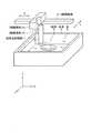
図1に示すように、超音波映像システム100は、超音波探触部1と、制御装置2と、位置制御装置3と、X軸駆動部21と、Y軸駆動部22と、Z軸駆動部23と、を備える。 As shown in FIG. 1, an
超音波映像システム100において、超音波探触部1は、試料4の表面全体を走査し、位置制御装置3は、超音波探触部1の焦点Fが試料4の表面に合うように、超音波探触部1の位置を決定し、制御装置2は、超音波探触部1の位置を制御する。試料4は、例えば、表面が湾曲する円盤形状のシリコンウェーハである。なお、本実施形態では、試料4として、表面が湾曲する円盤形状のシリコンウェーハを用いる場合を一例に挙げて説明するが、超音波映像システム100を用いて観察する試料は、これに限定されるものではない。 In the
超音波探触部1は、エンコーダ11と、圧電素子12と、を備える。超音波探触部1の下部は、水槽5に満たされた水6に浸漬される。 The
圧電素子12は、試料4の表面に対向するように設けられ、圧電膜及び圧電膜の両面に形成される電極を含む。両電極間に電圧が印加されることで、圧電膜が振動し、所定周波数の超音波が、圧電素子12から試料4の表面へと照射される。試料4の表面で反射された反射波は、圧電素子12へと伝搬し、両電極間に電圧が発生する。エンコーダ11は、超音波探触部1の位置(±X方向の位置、±Y方向の位置、±Z方向の位置)を検知し、超音波探触部1の位置を示す信号を、制御装置2へと出力する。 The
制御装置2の出力側は、X軸駆動部21、Y軸駆動部22、Z軸駆動部23と接続され、制御装置2の入力側は、位置制御装置3、エンコーダ11と接続される。 The output side of the
制御装置2は、エンコーダ11から入力される信号に基づいて、超音波探触部1の位置(±X方向の位置、±Y方向の位置、±Z方向の位置)を検知し、超音波探触部1の位置を示す信号を、位置制御装置3へと出力する。 The
制御装置2は、超音波探触部1の位置を、位置制御装置3が決定した位置に制御する。即ち、制御装置2は、位置制御装置3から入力される位置信号に基づいて、超音波探触部1を±X方向に駆動させるための制御信号を、X軸駆動部21へと出力する。また、制御装置2は、位置制御装置3から入力される位置信号に基づいて、超音波探触部1を±Y方向に駆動させるための制御信号を、Y軸駆動部22へと出力する。また、制御装置2は、位置制御装置3から入力される位置信号に基づいて、超音波探触部1を±Z方向に駆動させるための制御信号を、Y軸駆動部22へと出力する。 The
例えば、図2に示すように、X軸駆動部21が、矢印方向に駆動することで、超音波探触部1は±X方向に移動し、Y軸駆動部22が、矢印方向に駆動することで、超音波探触部1は±Y方向に移動し、Z軸駆動部23が、矢印方向に駆動することで、超音波探触部1は±Z方向に移動する。 For example, as shown in FIG. 2, when the
位置制御装置3は、走査制御部31と、タイミング制御部32と、発振器33と、入力部34と、処理部35と、画像生成部36と、記憶部37と、を備える。 The
走査制御部31は、制御装置2が±X方向における超音波探触部1の位置を制御するための位置信号を、制御装置2へと出力する。また、走査制御部31は、制御装置2が±Y方向における超音波探触部1の位置をするための位置信号を、制御装置2へと出力する。また、走査制御部31は、制御装置2が±Z方向における超音波探触部1の位置を制御するための位置信号を、制御装置2へと出力する。 The
走査制御部31は、制御装置2から入力される信号に基づいて、超音波探触部1の位置(±X方向の位置、±Y方向の位置、±Z方向の位置)を検知し、超音波探触部1の位置を示す信号を、タイミング制御部32へと出力する。 The
タイミング制御部32は、走査制御部31から入力される信号に基づいて、超音波探触部1が、試料4の表面に超音波を送信するタイミングを制御するタイミング信号を生成し、発振器33へと出力する。また、タイミング制御部32は、位置制御装置3が、試料4の表面から反射される反射波の反射信号を受信するタイミングを制御するタイミング信号を生成し、入力部34へと出力する。また、タイミング制御部32は、処理部35が、反射信号をゲート処理するタイミングを制御するタイミング信号を生成し、処理部35へと出力する。 The
発振器33は、タイミング制御部32から入力されるタイミング信号に基づいて、インパルス信号を、超音波探触部1へと送信する。これにより、圧電膜に形成される両電極間に電圧が印加され、超音波が、圧電素子12から試料4の表面へと、照射される。 The
入力部34は、アンプ及びA/D変換器を備えており、タイミング制御部32から入力されるタイミング信号に基づいて、試料4の表面から反射される反射波の反射信号を受信し、受信信号を処理部35へと出力する。アンプは、反射信号を増幅し、A/D変換器は、反射信号を、アナログ信号からデジタル信号へと変換する。 The
処理部35は、タイミング制御部32から入力されるタイミング信号に基づいて、反射信号をゲート処理し、反射波の変位(例えば、反射波の振幅情報、反射波の時間情報、等)を検出し、検出信号を、画像生成部36へと出力する。また、処理部35は、所定期間における反射波の変位を切り出すために、追従ゲートを生成する。 The
処理部35は、超音波探触部1が試料4の表面の所定ライン(例えば、3ライン目)を走査する際の、偏差(後述の説明参照)を算出し、記憶部37に記憶させる。また、処理部35は、該偏差をゼロとするように、超音波探触部1が試料4の表面の次のライン(例えば、4ライン目)を走査する際の、試料4の表面に対して垂直方向(±Z方向)における超音波探触部1の位置を決定し、位置信号を、走査制御部31へと出力する。なお、本明細書において、ゼロとは、厳密にゼロであることに限定されず、実質的にゼロであることを意味するものとし、ゼロから測定誤差の範囲も含むものとする。 The
詳細な説明は後述するが、偏差とは、試料表面に超音波を送信してから反射波を受信するまでの時間(実時間)と、基準時間との時間差である。また、基準時間とは、超音波探触部1と試料4の表面との距離が、超音波探触部1の焦点距離と一致する場合において、試料表面に超音波を送信してから反射波を受信するまでの時間であり、実時間に対して基準となる時間である。 Although the detailed description will be described later, the deviation is the time difference between the time (real time) from when the ultrasonic wave is transmitted to the sample surface until the reflected wave is received and the reference time. The reference time is a reflected wave after transmitting an ultrasonic wave to the sample surface when the distance between the
試料4の表面が、超音波探触部1に近づくように湾曲していれば(超音波探触部1と試料4の表面との距離が、超音波探触部1の焦点距離より短ければ)、実時間は短くなり、偏差はプラスの値となる。また、試料4の表面が、超音波探触部1から離れるように湾曲していれば(超音波探触部1と試料4の表面との距離が、超音波探触部1の焦点距離より長ければ)、実時間は長くなり、偏差はマイナスの値となる。即ち、超音波探触部1と試料表面との距離は、偏差(時間差)に依存する。 If the surface of the
従って、処理部35が、試料4の表面の湾曲に合わせて、±Z方向における超音波探触部1の位置を決定することで、超音波映像システム100において、高解像度の画像生成が可能になる。 Therefore, the
また、所定ラインにおける試料4の表面の湾曲と、次のラインにおける試料4の表面の湾曲と、は略等しいと考えられる。処理部35が、所定ラインに対して算出した偏差に基づいて、次のラインを走査する際の、超音波探触部1の位置を決定することで、次のラインに対して算出した偏差に基づいて、次のラインを走査する際の、超音波探触部1の位置を決定することと、略同様の効果を得ることができる。即ち、処理部35が、試料表面の湾曲が完全に等しいラインを走査して、超音波探触部の位置を決定することと、略同様の効果を得ることができる。これにより、超音波映像システム100において、超音波探触部1の正確な位置補正が可能になる。 Further, it is considered that the curvature of the surface of the
また、処理部35は、所定の時間間隔で測定点を設定し、該測定点ごとに、偏差を算出する。 The
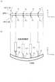
図3は、超音波探触部1が連続的に+X方向に進行し、偏差を算出するための測定を、各測定点において行う場合の概念図である。図3(a)は、所定の時間間隔で設定される測定点を、+X方向に4点とった場合において、超音波探触部1が、試料4の表面を+X方向に走査する様子を示した平面図である。図3(b)は、所定の時間間隔で設定される測定点を、+X方向に4点とった場合において、超音波探触部1が、試料4の表面を+X方向に走査する様子を示した側面図である。 FIG. 3 is a conceptual diagram when the
X1は、所定ライン(例えば、3ライン目)における第1の測定点である。P1は、第1の測定点X1で算出した偏差に基づいて、次のライン(例えば、4ライン目)における位置補正を行う点であると同時に、次のライン(例えば、4ライン目)における第1の測定点となる点である。 X1 is a first measurement point on a predetermined line (for example, the third line). P1 is a point for performing position correction in the next line (for example, the fourth line) based on the deviation calculated at the first measurement point X1, and at the same time, the first line in the next line (for example, the fourth line). This is a point that becomes one measurement point.
X2は、所定ライン(例えば、3ライン目)における第2の測定点である。P2は、第2の測定点X2で算出した偏差に基づいて、次のライン(例えば、4ライン目)における位置補正を行う点であると同時に、次のライン(例えば、4ライン目)における第2の測定点となる点である。 X2 is a second measurement point on a predetermined line (for example, the third line). P2 is a point for performing position correction on the next line (for example, the fourth line) based on the deviation calculated at the second measurement point X2, and at the same time, the second line (for example, the fourth line). This is the point that becomes the second measurement point.
X3は、所定ライン(例えば、3ライン目)における第3の測定点である。P3は、第3の測定点X3で算出した偏差に基づいて、次のライン(例えば、4ライン目)における位置補正を行う点であると同時に、次のライン(例えば、4ライン目)における第3の測定点となる点である。 X3 is a third measurement point on a predetermined line (for example, the third line). P3 is a point for performing position correction in the next line (for example, the fourth line) based on the deviation calculated at the third measurement point X3, and at the same time, the third line in the next line (for example, the fourth line). 3 is a point to be measured.
X4は、所定ライン(例えば、3ライン目)における第4の測定点である。P4は、第4の測定点X4で算出した偏差に基づいて、次のライン(例えば、4ライン目)における位置補正を行う点であると同時に、次のライン(例えば、4ライン目)における第4の測定点となる点である。 X4 is a fourth measurement point on a predetermined line (for example, the third line). P4 is a point for performing position correction on the next line (for example, the fourth line) based on the deviation calculated at the fourth measurement point X4, and at the same time, the point on the next line (for example, the fourth line). This is a point to be a measurement point of 4.
例えば、処理部35は、試料4表面の所定ライン(例えば、3ライン目)における第1の測定点X1での、偏差を算出し、記憶部37に記憶させる。そして、処理部35は、第1の測定点X1で算出した偏差に基づいて、次のライン(例えば、4ライン目)の点P1における超音波探触部1の±Z方向の位置を決定する。 For example, the
同様に、例えば、処理部35は、試料4表面の所定ライン(例えば、3ライン目)における第2の測定点X2での、偏差を算出し、記憶部37に記憶させる。そして、処理部35は、第2の測定点X2で算出した偏差に基づいて、次のライン(例えば、4ライン目)の点P2における超音波探触部1の±Z方向の位置を決定する。 Similarly, for example, the
同様に、例えば、処理部35は、試料4表面の所定ライン(例えば、3ライン目)における第3の測定点X3での、偏差を算出し、記憶部37に記憶させる。そして、処理部35は、第3の測定点X3で算出した偏差に基づいて、次のライン(例えば、4ライン目)の点P3における超音波探触部1の±Z方向の位置を決定する。 Similarly, for example, the
同様に、例えば、処理部35は、試料4表面の所定ライン(例えば、3ライン目)における第4の測定点X4での、偏差を算出し、記憶部37に記憶させる。そして、処理部35は、第4の測定点X4で算出した偏差に基づいて、次のライン(例えば、4ライン目)の点P4における超音波探触部1の±Z方向の位置を決定する。 Similarly, for example, the
即ち、処理部35は、所定の時間間隔で設定したn−1ライン目(例えば、3ライン目)の測定点ごとに、偏差を算出する。また、処理部35は、nライン目(例えば、4ライン目)の測定点ごとに、対応するn−1ライン目(例えば、3ライン目)の測定点で算出した偏差をゼロとするように、試料表面に対して垂直方向(±Z方向)における超音波探触部1の位置を決定する。 That is, the
第1の測定点X1と点P1との間隔は、極めて小さい。従って、例えば、3ライン目における第1の測定点X1で算出した偏差に基づいて、4ライン目の点P1における超音波探触部1の±Z方向の位置を決定することは、4ライン目における点P1で算出した偏差に基づいて、4ライン目の点P1における超音波探触部1の±Z方向の位置を決定することと、略同様であると考えることができる。これにより、超音波探触部1が4ライン目を走査する際、超音波探触部1と試料4の表面との距離Dを一定に保つことができる。 The interval between the first measurement point X1 and the point P1 is extremely small. Therefore, for example, determining the position in the ± Z direction of the
同様に、第2の測定点X2と点P2との間隔は、極めて小さい。従って、例えば、3ライン目における第2の測定点X2で算出した偏差に基づいて、4ライン目の点P2における超音波探触部1の±Z方向の位置を決定することは、4ライン目における点P2で算出した偏差に基づいて、4ライン目の点P2における超音波探触部1の±Z方向の位置を決定することと、略同様であると考えることができる。これにより、超音波探触部1が4ライン目を走査する際、超音波探触部1と試料4の表面との距離Dを一定に保つことができる。 Similarly, the interval between the second measurement point X2 and the point P2 is extremely small. Therefore, for example, determining the position in the ± Z direction of the
同様に、第3の測定点X3と点P3との間隔は、極めて小さい。従って、例えば、3ライン目における第3の測定点X3で算出した偏差に基づいて、4ライン目の点P3における超音波探触部1の±Z方向の位置を決定することは、4ライン目における点P3で算出した偏差に基づいて、4ライン目の点P3における超音波探触部1の±Z方向の位置を決定することと、略同様であると考えることができる。これにより、超音波探触部1が4ライン目を走査する際、超音波探触部1と試料4の表面との距離Dを一定に保つことができる。 Similarly, the distance between the third measurement point X3 and the point P3 is extremely small. Therefore, for example, determining the position in the ± Z direction of the
同様に、第4の測定点X4と点P4との間隔は、極めて小さい。従って、例えば、3ライン目における第4の測定点X4で算出した偏差に基づいて、4ライン目の点P4における超音波探触部1の±Z方向の位置を決定することは、4ライン目における点P4で算出した偏差に基づいて、4ライン目の点P4における超音波探触部1の±Z方向の位置を決定することと、略同様であると考えることができる。これにより、超音波探触部1が4ライン目を走査する際、超音波探触部1と試料4の表面との距離Dを一定に保つことができる。 Similarly, the distance between the fourth measurement point X4 and the point P4 is extremely small. Therefore, for example, determining the position in the ± Z direction of the
なお、超音波探触部1が試料4の表面の、所定ラインを走査する際の、偏差を算出するための測定を行う間隔であるが、試料4の表面の凹凸が少なく、湾曲が小さい部分においては、測定を行う間隔を大きくし、試料4の表面の凹凸が多く、湾曲が大きい部分においては、測定を行う間隔を小さくすることが可能である。湾曲が大きい部分において、集中的に測定を行い、偏差を算出することで、超音波映像システム100において、効率的な位置補正が可能になる。 In addition, although it is the space | interval which performs the measurement for calculating the deviation when the
画像生成部36は、処理部35から入力される信号に基づいて、画像を生成する。上述のように、±Z方向における超音波探触部1の位置は、適切な位置(超音波探触部1の焦点Fが試料4の表面に合う位置)に調整されるため、画像生成部36は、解像度の高い画像を生成することができる。 The
記憶部37は、超音波探触部1が試料4の表面の、所定ラインを走査する際に、処理部35が算出する偏差を記憶する。また、記憶部37は、超音波探触部1が試料4の表面の、次のラインを走査する際に、処理部35が使用する偏差を記憶する。従って、記憶部37は、少なくとも2ライン分の偏差を記憶するメモリ容量を有していれば良い。 The
記憶部37は、予め設定される所定の基準時間を記憶する。また、記憶部37は、追従ゲートの始点、追従ゲートの終点、電圧波形がピークを有する点、基準の電圧波形がピークを有する点、等を記憶する。 The
本実施形態に係る位置制御装置3によれば、記憶部が、超音波探触部が試料表面の所定ラインを走査する際の、偏差を記憶し、処理部が、該偏差がゼロとなるように、超音波探触部が試料表面の次のラインを走査する際の、超音波探触部の位置を決定する。これにより、測定時間と作業コストを減少させることができる。 According to the
本実施形態に係る超音波映像システム100によれば、超音波探触部1が、試料全体を1度走査するのみで、超音波探触部1を適切な位置に調整できる。これにより、測定時間と作業コストを減少させることができる。また、試料を高分解能で観察するためには、超音波探触部1が、試料全体を2度走査しなければならなかったという、従来の問題点を改善することができる。 According to the
≪偏差の算出≫
次に、図4、図5を参照して、上述した偏差について説明する。図4は、時間と反射波の変位との関係を示すグラフである。図4(a)は、基準の電圧波形を示しており、図4(b)は、実際に測定された電圧波形を示している。横軸は時間[s]、縦軸は電圧(反射波の変位)[V]を示している。≪Calculation of deviation≫
Next, the deviation described above will be described with reference to FIGS. FIG. 4 is a graph showing the relationship between time and the displacement of the reflected wave. FIG. 4A shows a reference voltage waveform, and FIG. 4B shows an actually measured voltage waveform. The horizontal axis represents time [s] and the vertical axis represents voltage (displacement of reflected wave) [V].
処理部35は、追従ゲートGを生成し、反射波の変位を追従ゲートG内にプロットし、追従ゲートG内における基準の電圧波形と、追従ゲートG内における実際に測定された電圧波形と、を比較して、偏差を算出する。 The
図4(a)に示すように、追従ゲートGの始点の時刻をt0[s]、追従ゲートGの終点の時刻をt1[s]、基準の電圧波形がピークを有する時刻をtx1[s]とすると、追従ゲートGの始点から、基準の電圧波形がピークを有するまでの時間は、tA[s](所定の基準時間)となる。As shown in FIG. 4A, the time of the start point of the tracking gate G is t0 [s], the time of the end point of the tracking gate G is t1 [s], and the time when the reference voltage waveform has a peak is tx1. Assuming [s], the time from the start point of the tracking gate G until the reference voltage waveform has a peak is tA [s] (predetermined reference time).
図4(b)に示すように、追従ゲートGの始点の時刻をt0[s]、追従ゲートGの終点の時刻をt1[s]、実際に測定された電圧波形がピークを有する時刻をtx2[s]とすると、追従ゲートGの始点から実際に測定された電圧波形がピークを有するまでの時間は、tB[s](所定の実時間)となる。As shown in FIG. 4B, the time of the start point of the tracking gate G is t0 [s], the time of the end point of the tracking gate G is t1 [s], and the actually measured voltage waveform has a peak time. Is tx2 [s], the time from the start point of the tracking gate G until the actually measured voltage waveform has a peak is tB [s] (predetermined real time).
処理部35は、追従ゲートの始点から電圧波形がピークを有するまでの時間(tA[s])と、追従ゲートの始点から基準の電圧波形がピークを有するまでの時間(tB[s])との時間差(tA−tB[s])を、偏差として、算出する。即ち、処理部35は、追従ゲートを生成し、所定期間における反射波の変位を切り出して、偏差を算出することが可能である。なお、追従ゲートGは、処理部35によって、任意に設定されるものである。The
図5は、処理部35に含まれるゲート回路350の動作を示す図である。 FIG. 5 is a diagram illustrating the operation of the
図5に示すように、ゲート回路350には、反射波を取り込んだ波形データ、ゲートに係るデータが入力されてゲート処理が行われ、反射波の変位が出力される。ゲートに係るデータは、ゲートの開始タイミングと、ゲートの幅と、判定閾値とを含んで構成される。ゲート回路350は、予め設定されたゲート内の反射波に対して、この判定閾値を超えた反射波の変位を検出する。 As shown in FIG. 5, the
≪超音波探触部の走査≫
次に、図6を参照して、超音波探触部1による走査について説明する。≪Scanning of ultrasonic probe≫
Next, scanning by the
図6(a)は、超音波探触部1が、試料4の表面を±X方向に走査する場合の平面図である。図6(b)は、超音波探触部1が、試料4の表面を±X方向に走査する場合の側面図である。 FIG. 6A is a plan view when the
図6(a)に示すように、まず、超音波探触部1は、試料表面の1ライン目を、+X方向に走査する。処理部35は、1ライン目における偏差を算出し、記憶部37は、1ライン目における偏差を記憶する。なお、超音波探触部1が試料表面の1ライン目を走査する場合、±Z方向における超音波探触部1の位置を決定するための偏差が、未だ算出されていないため、±Z方向における超音波探触部1の位置を変えずに、超音波探触部1は、試料表面の1ライン目を走査する。 As shown in FIG. 6A, first, the
次に、超音波探触部1は、−Y方向に所定ピッチだけ移動する。該ピッチは、極めて短い距離(具体的には、0.01mm以下)である。従って、1ライン目における試料表面の湾曲と、2ライン目における試料表面の湾曲とは、略等しいとすることができる。 Next, the
次に、超音波探触部1は、試料表面の2ライン目を、−X方向に走査する。処理部35は、記憶部37に記憶させた1ライン目における偏差に基づいて、超音波探触部1が、試料表面の2ライン目を−X方向に走査する際の、±Z方向における超音波探触部1の位置を決定する。走査制御部31は、±Z方向における超音波探触部1の位置を制御するための位置信号を、制御装置2へと出力し、制御装置2は、±Z方向における超音波探触部1の位置を、適切な位置に調整する。適切な位置とは、図6(b)に示すように、超音波探触部1と試料4の表面との距離Dが一定となる位置である。 Next, the
また、処理部35は、2ライン目における偏差を算出し、記憶部37は、2ライン目における偏差を記憶する。このとき、記憶部37は、1ライン目における偏差及び2ライン目における偏差を記憶する。 Further, the
次に、超音波探触部1は、−Y方向に所定ピッチだけ移動する。該ピッチは、極めて短い距離(具体的には、0.01mm以下)である。従って、2ライン目における試料表面の湾曲と、3ライン目における試料表面の湾曲とは、略等しいとすることができる。 Next, the
次に、超音波探触部1は、試料表面の3ライン目を、+X方向に走査する。処理部35は、記憶部37に記憶させた2ライン目における偏差に基づいて、超音波探触部1が、試料表面の3ライン目を+X方向に走査する際の、±Z方向における超音波探触部1の位置を決定する。走査制御部31は、±Z方向における超音波探触部1の位置を制御するための位置信号を、制御装置2へと出力し、制御装置2は、±Z方向における超音波探触部1の位置を、適切な位置に調整する。適切な位置とは、図6(b)に示すように、超音波探触部1と試料4の表面との距離Dが一定となる位置である。 Next, the
また、処理部35は、3ライン目における偏差を算出し、記憶部37は、3ライン目における偏差を記憶する。このとき、記憶部37は、1ライン目における偏差、2ライン目における偏差、3ライン目における偏差、の全てを記憶しても良いし、2ライン目における偏差、3ライン目における偏差、のみを記憶しても良い。少なくとも、2ライン分(2ライン目における偏差、3ライン目における偏差)を記憶していれば良い。 The
次に、超音波探触部1は、−Y方向に所定ピッチだけ移動する。該ピッチは、極めて短い距離(具体的には、0.01mm以下)である。従って、3ライン目における試料表面の湾曲と、4ライン目における試料表面の湾曲とは、略等しいとすることができる。 Next, the
超音波探触部1は、上述のような走査を繰り返し、試料4の表面の全てのラインを走査する。これにより、試料4の表面の画像が生成される。 The
本実施形態に係る超音波映像システム100によれば、表面が湾曲する試料に対しても、超音波探触部を試料全体に対して1度走査させるのみで、超音波探触部と試料表面との距離Dを一定に保持し、画像を生成することができる。これにより、超音波探触部を試料全体に対して2度走査させた場合における、画像の解像度を維持しつつ、測定時間と作業コストを減少させた超音波映像システム100の提供が可能となる。 According to the
なお、従来の超音波映像システムは、超音波探触部が試料全体を2度走査するため、機械的な処理回数は、本実施の形態に係る超音波映像システム100と比較して、2倍になる。一方、本実施の形態に係る超音波映像システム100は、処理部が、偏差を算出しつつ、超音波探触部の位置を決定するため、処理部の処理量は、従来の超音波映像システムと比較して、2倍になる。しかしながら、2倍のデータ処理を行う場合における測定時間と作業コストは、2倍の走査処理を行う場合における測定時間と作業コストと比較して、極めて小さい。従って、従来の超音波映像システムと比較すると、本実施の形態に係る超音波映像システム100は、大幅に、測定時間と作業コストを低減できることになる。 In the conventional ultrasound imaging system, since the ultrasound probe scans the entire sample twice, the number of mechanical processes is twice that of the
≪位置制御装置の動作≫
次に、図6及び図7を参照して、本発明の実施形態に係る位置制御装置3の動作について、説明する。<< Operation of position control device >>
Next, with reference to FIG.6 and FIG.7, operation | movement of the
図7は、本発明の実施形態に係る位置制御装置3の動作を示すフローチャートである。 FIG. 7 is a flowchart showing the operation of the
ステップS501において、処理部35は、超音波探触部1が試料4の表面の1ライン目を走査する際の偏差を算出し、記憶部37は、該偏差を記憶する。 In step S501, the
ステップS502において、処理部35は、1ライン目(n−1ライン目)における偏差に基づいて、超音波探触部1が試料4の表面の2ライン目(nライン目)を走査する際の、超音波探触部1の位置を決定する。n(n≧2)は、ライン番号を示す変数である。 In step S <b> 502, the
ステップS503において、処理部35は、超音波探触部1が試料4の表面の2ライン目(nライン目)を走査する際の偏差を算出し、記憶部37は、該偏差を記憶する。 In step S503, the
ステップS504において、処理部35は、超音波探触部1が試料4の表面の全てのラインの走査を終了したか否かを判断する。処理部35は、超音波探触部1が試料4の表面の全てのラインの走査を終了していないと判断する場合(ステップS504→No)、ステップS505の処理を行う。一方、処理部35は、超音波探触部1が試料4の表面の全てのラインの走査を終了したと判断する場合(ステップS504→Yes)、ステップS506の処理を行う。 In step S <b> 504, the
ステップS505において、処理部35は、ライン番号を示す変数n(n≧2)を、1つ増加させる。即ち、nを、2から3へと増加させる。 In step S505, the
再び、ステップS502において、処理部35は、2ライン目(n−1ライン目)における偏差に基づいて、超音波探触部1が試料4の表面の3ライン目(nライン目)を走査する際の、超音波探触部1の位置を決定する。 Again, in step S502, the
再び、ステップS503において、処理部35は、超音波探触部1が試料4の表面の3ライン目(nライン目)を走査する際の偏差を算出し、記憶部37は、該偏差を記憶する。 Again, in step S503, the
再び、ステップS504において、処理部35は、超音波探触部1が試料4の表面の全てのラインの走査を終了したか否かを判断する。処理部35は、超音波探触部1が試料4の表面の全てのラインの走査を終了していないと判断する場合(ステップS504→No)、ステップS505の処理を行う。一方、処理部35は、超音波探触部1が試料4の表面の全てのラインの走査を終了したと判断する場合(ステップS504→Yes)、ステップS506の処理を行う。 Again, in step S504, the
再び、ステップS505において、処理部35は、ライン番号を示す変数n(n≧2)を、1つ増加させる。即ち、nを、3から4へと増加させる。 Again, in step S505, the
超音波探触部1が試料4の表面の全てのラインの走査を終了するまで、上述のように、ステップS502〜S505までの処理を繰り返す。 As described above, the processing from steps S502 to S505 is repeated until the
ステップS506において、画像生成部36は、試料4の表面の画像を生成し、一連の処理を終了する。 In step S506, the
上述の位置制御方法によれば、測定時間と作業コストを減少させることができる。 According to the above-described position control method, the measurement time and the operation cost can be reduced.
100 超音波映像システム
1 超音波探触部
2 制御装置
3 位置制御装置
35 処理部
37 記憶部
DESCRIPTION OF
Claims (9)
Translated fromJapanese該n−1ライン目の偏差に基づいて、前記超音波探触部が試料表面のnライン目を走査する際の、前記超音波探触部の位置を決定し、且つ、前記超音波探触部が試料表面のnライン目を走査する際に、超音波を送信してから反射波を受信するまでの時間と基準時間とのnライン目の偏差を算出する処理部と、
を備えることを特徴とする位置制御装置。When the ultrasonic probe scans the (n-1) th line on the sample surface,the deviationof the (n-1) th line between the time from when the ultrasonic wave is transmitted until the reflected wave is received and the reference time is measured as theultrasonic wave. A storage unitfor storing theprobe unit before moving it to the n-line ;
Based onthe deviationof the (n-1) th line, the position of the ultrasonic probe when the ultrasonic probe scans the nth line on the sample surface is determined, and the ultrasonic probe When the unit scans the nth line on the sample surface, a processing unit that calculatesthe deviation of thenth line between the time from when the ultrasonic wave is transmitted until the reflected wave is received and the reference time;
A position control device comprising:
所定の時間間隔で設定した測定点ごとに、前記偏差を算出し、前記偏差を前記記憶部に記憶させる、
ことを特徴とする請求項1に記載の位置制御装置。The processor is
For each measurement point set at a predetermined time interval, the deviation is calculated, and the deviation is stored in the storage unit.
The position control device according to claim 1.
前記偏差をゼロとするように、前記試料表面に対して垂直方向における前記超音波探触部の位置を決定する、
ことを特徴とする請求項1又は請求項2に記載の位置制御装置。The processor is
Determining the position of the ultrasonic probe in a direction perpendicular to the sample surface so that the deviation is zero;
The position control device according to claim 1 or 2, wherein
前記nライン目の測定点ごとに、対応するn−1ライン目の測定点で算出した前記n−1ライン目の偏差をゼロとするように、前記試料表面に対して垂直方向における前記超音波探触部の位置を決定する、
ことを特徴とする請求項1又は請求項2に記載の位置制御装置。The processor is
For each n-th measurement point, the ultrasonic wave in the direction perpendicular to the sample surface is set such thatthe deviationof the n- 1thline calculated at the corresponding measurement point of the (n-1) th line is zero. Determine the position of the probe,
The position control device according to claim 1 or 2, wherein
追従ゲートを生成し、
前記追従ゲートの始点から電圧波形がピークを有するまでの時間と、前記追従ゲートの始点から基準の電圧波形がピークを有するまでの時間とを比較して、前記偏差を算出する
ことを特徴とする請求項1から請求項4のいずれか一項に記載の位置制御装置。The processor is
Generate a tracking gate,
Comparing the time from the start point of the tracking gate to the peak of the voltage waveform with the time from the start point of the tracking gate to the peak of the reference voltage waveform, and calculating the deviation. The position control device according to any one of claims 1 to 4.
該超音波探触部をnラインに移動させるステップと、
該n−1ライン目の偏差に基づいて、前記超音波探触部が試料表面のnライン目を走査する際の、前記超音波探触部の位置を決定するステップと、
前記超音波探触部が試料表面のnライン目を走査し、且つ、超音波を送信してから反射波を受信するまでの時間と基準時間とのnライン目の偏差を算出するステップと、
を備えることを特徴とする位置制御方法。When the ultrasonic probe scans the (n-1) th line on the sample surface,the deviationof the (n-1) th line between the time from when the ultrasonic wave is transmitted until the reflected wave is received and the reference time is stored. Steps,
Moving the ultrasonic probe to n lines;
Determining the position of the ultrasonic probe when the ultrasonic probe scans the nth line on the sample surface based onthe deviationof the n-1st line ;
The ultrasonic probe scans the nth line on the sample surface, and calculatesthe deviation of thenth line between the time from when the ultrasonic wave is transmitted until the reflected wave is received and the reference time;
A position control method comprising:
所定の時間間隔で設定したn−1ライン目の測定点ごとに、前記n−1ライン目の偏差を算出し、
前記超音波探触部の位置を決定するステップは、
前記nライン目の測定点ごとに、対応するn−1ライン目の測定点の前記n−1ライン目の偏差をゼロとするように、前記試料表面に対して垂直方向における前記超音波探触部の位置を決定する、
ことを特徴とする請求項6に記載の位置制御方法。Storing the deviation comprises:
For each measurement point of the (n-1) th line set at a predetermined time interval,the deviationof the (n-1) th line is calculated,
Determining the position of the ultrasonic probe;
For each n-th measurement point, the ultrasonic probe in the direction perpendicular to the sample surface is set so thatthe deviation of the corresponding n-1th measurement point is zero. Determine the position of the part,
The position control method according to claim 6.
前記超音波探触部が試料表面のn−1ライン目を走査した際の、超音波を送信してから反射波を受信するまでの時間と基準時間とのn−1ライン目の偏差を超音波探触部をnラインに移動させる前に記憶し、該n−1ライン目の偏差に基づいて、前記超音波探触部が試料表面のnライン目を走査する際の、前記超音波探触部の位置を決定する位置制御装置と、
前記超音波探触部の位置を、前記位置制御装置が決定した位置に制御する制御装置と、
を備え、
前記位置制御装置は、nライン目を走査する際に、超音波を送信してから反射波を受信するまでの時間と基準時間とのnライン目の偏差を算出することを特徴とする超音波映像システム。An ultrasonic probe that transmits ultrasonic waves to the sample surface and receives reflected waves from the sample surface;
Wherein when the ultrasonic probe unit is scanning the n-1-th line of the sample surface, then-1-th line of the difference betweenthe time and the reference time until receiving the reflected waves from the transmission of the ultrasonic wavesuper The ultrasonic probe is storedbefore moving to then- th line, and the ultrasonic probe when the ultrasonic probe scans the n-th line on the sample surface based onthe deviationof the (n-1 ) th line. A position control device for determining the position of the touch part;
A control device for controlling the position of the ultrasonic probe to the position determined by the position control device;
With
The position control device calculatesthe deviation of thenth line between the time from when the ultrasonic wave is transmitted until the reflected wave is received and the reference time when scanning thenth line. Video system.
所定の時間間隔で設定したn−1ライン目の測定点ごとに、前記n−1ライン目の偏差を算出し、前記n−1ライン目の測定点に対応するnライン目の測定点ごとに、前記n−1ライン目の偏差をゼロとするように前記超音波探触部の位置を決定する、
ことを特徴とする請求項8に記載の超音波映像システム。The position control device includes:
For each measurement point on the (n-1) th line set at a predetermined time interval,the deviation on the (n-1) th line is calculated, and for each measurement point on the nth line corresponding to the measurement point on the (n-1) th line. Determining the position of the ultrasonic probe so thatthe deviationof the (n-1) th line is zero.
The ultrasonic imaging system according to claim 8.
Priority Applications (7)
| Application Number | Priority Date | Filing Date | Title |
|---|---|---|---|
| JP2017015187AJP6273055B1 (en) | 2017-01-31 | 2017-01-31 | POSITION CONTROL DEVICE, POSITION CONTROL METHOD, AND ULTRASONIC VIDEO SYSTEM |
| EP18748514.9AEP3578967B1 (en) | 2017-01-31 | 2018-01-29 | Position control device, position control method, and ultrasound imaging system |
| US16/480,984US20200000431A1 (en) | 2017-01-31 | 2018-01-29 | Position Control Device, Position Control Method, and Ultrasonic Imaging System |
| KR1020197021382AKR102270030B1 (en) | 2017-01-31 | 2018-01-29 | Position control device, position control method, and ultrasound imaging system |
| PCT/JP2018/002794WO2018143134A1 (en) | 2017-01-31 | 2018-01-29 | Position control device, position control method, and ultrasound imaging system |
| CN201880008632.9ACN110268258B (en) | 2017-01-31 | 2018-01-29 | Position control device, position control method, and ultrasonic imaging system |
| TW107103307ATWI667475B (en) | 2017-01-31 | 2018-01-30 | Position control device, position control method and ultrasonic image system |
Applications Claiming Priority (1)
| Application Number | Priority Date | Filing Date | Title |
|---|---|---|---|
| JP2017015187AJP6273055B1 (en) | 2017-01-31 | 2017-01-31 | POSITION CONTROL DEVICE, POSITION CONTROL METHOD, AND ULTRASONIC VIDEO SYSTEM |
Publications (2)
| Publication Number | Publication Date |
|---|---|
| JP6273055B1true JP6273055B1 (en) | 2018-01-31 |
| JP2018124111A JP2018124111A (en) | 2018-08-09 |
Family
ID=61074752
Family Applications (1)
| Application Number | Title | Priority Date | Filing Date |
|---|---|---|---|
| JP2017015187AActiveJP6273055B1 (en) | 2017-01-31 | 2017-01-31 | POSITION CONTROL DEVICE, POSITION CONTROL METHOD, AND ULTRASONIC VIDEO SYSTEM |
Country Status (7)
| Country | Link |
|---|---|
| US (1) | US20200000431A1 (en) |
| EP (1) | EP3578967B1 (en) |
| JP (1) | JP6273055B1 (en) |
| KR (1) | KR102270030B1 (en) |
| CN (1) | CN110268258B (en) |
| TW (1) | TWI667475B (en) |
| WO (1) | WO2018143134A1 (en) |
Families Citing this family (2)
| Publication number | Priority date | Publication date | Assignee | Title |
|---|---|---|---|---|
| JP7028320B2 (en) | 2018-06-05 | 2022-03-02 | 株式会社Ihi | Unsaturated hydrocarbon production equipment |
| JP7093884B1 (en)* | 2021-11-30 | 2022-06-30 | 株式会社日立パワーソリューションズ | Array type ultrasonic image device and ultrasonic image display method |
Family Cites Families (14)
| Publication number | Priority date | Publication date | Assignee | Title |
|---|---|---|---|---|
| JP2720077B2 (en)* | 1989-08-21 | 1998-02-25 | 日立建機株式会社 | Ultrasonic flaw detector |
| EP0489161A4 (en)* | 1989-08-21 | 1992-07-08 | Hitachi Construction Machinery Co., Ltd. | Ultrasonic flaw detector |
| JP2640878B2 (en)* | 1990-05-30 | 1997-08-13 | 日立建機株式会社 | Ultrasound imaging equipment |
| KR0171605B1 (en)* | 1990-05-30 | 1999-05-01 | 오까다 모도 | Ultrasonic inspection and imaging instrument |
| JPH04134065U (en)* | 1991-06-03 | 1992-12-14 | 日立建機株式会社 | Ultrasonic flaw detection equipment |
| US5608690A (en)* | 1995-03-02 | 1997-03-04 | Acuson Corporation | Transmit beamformer with frequency dependent focus |
| JP2003322646A (en)* | 2002-04-30 | 2003-11-14 | Hitachi Kenki Fine Tech Co Ltd | Ultrasonic image apparatus |
| JP2008076055A (en)* | 2006-09-19 | 2008-04-03 | Ohara Inc | Device and method of measuring propagation time of ultrasound wave |
| JP5155692B2 (en)* | 2008-02-26 | 2013-03-06 | 東芝プラントシステム株式会社 | Ultrasonic inspection equipment |
| US20090287450A1 (en)* | 2008-05-16 | 2009-11-19 | Lockheed Martin Corporation | Vision system for scan planning of ultrasonic inspection |
| US20170049331A1 (en)* | 2011-05-02 | 2017-02-23 | Canon Kabushiki Kaisha | Object information acquiring apparatus and method of controlling the same |
| JP5655017B2 (en) | 2012-02-20 | 2015-01-14 | 株式会社日立パワーソリューションズ | Work suction and fixing device and ultrasonic inspection system |
| JP5764251B1 (en)* | 2014-12-25 | 2015-08-19 | 株式会社日立パワーソリューションズ | Ultrasonic imaging apparatus and observation method using the same |
| US10575816B2 (en)* | 2017-01-25 | 2020-03-03 | Insightec, Ltd. | Cavitation localization |
- 2017
- 2017-01-31JPJP2017015187Apatent/JP6273055B1/enactiveActive
- 2018
- 2018-01-29CNCN201880008632.9Apatent/CN110268258B/enactiveActive
- 2018-01-29KRKR1020197021382Apatent/KR102270030B1/enactiveActive
- 2018-01-29EPEP18748514.9Apatent/EP3578967B1/enactiveActive
- 2018-01-29USUS16/480,984patent/US20200000431A1/ennot_activeAbandoned
- 2018-01-29WOPCT/JP2018/002794patent/WO2018143134A1/ennot_activeCeased
- 2018-01-30TWTW107103307Apatent/TWI667475B/enactive
Also Published As
| Publication number | Publication date |
|---|---|
| EP3578967A4 (en) | 2020-09-09 |
| EP3578967B1 (en) | 2024-05-01 |
| JP2018124111A (en) | 2018-08-09 |
| CN110268258A (en) | 2019-09-20 |
| KR102270030B1 (en) | 2021-06-28 |
| KR20190099491A (en) | 2019-08-27 |
| US20200000431A1 (en) | 2020-01-02 |
| TWI667475B (en) | 2019-08-01 |
| WO2018143134A1 (en) | 2018-08-09 |
| CN110268258B (en) | 2022-09-30 |
| TW201830011A (en) | 2018-08-16 |
| EP3578967A1 (en) | 2019-12-11 |
Similar Documents
| Publication | Publication Date | Title |
|---|---|---|
| US7454973B2 (en) | Ultrasonic inspection method and ultrasonic inspection equipment | |
| JP5155693B2 (en) | Ultrasonic inspection equipment | |
| JP5298439B2 (en) | Ultrasonic flaw detector, sensitivity correction method for the ultrasonic device, and ultrasonic flaw detector method | |
| WO2009151142A1 (en) | Ultrasonic apparatus and control method therefor | |
| KR101723752B1 (en) | Ultrasonic imaging device and observing method using the same | |
| US10231709B2 (en) | Ultrasound diagnostic apparatus, signal processing method for ultrasound diagnostic apparatus, and recording medium | |
| JP6273055B1 (en) | POSITION CONTROL DEVICE, POSITION CONTROL METHOD, AND ULTRASONIC VIDEO SYSTEM | |
| US20150374339A1 (en) | Ultrasound diagnostic apparatus, signal processing method for ultrasound diagnostic apparatus, and recording medium | |
| JP5358636B2 (en) | Ultrasonic diagnostic apparatus and ultrasonic image generation method | |
| CN106028952A (en) | Acoustic wave processing device, signal processing method and program of acoustic wave processing device | |
| WO2014050889A1 (en) | Ultrasonic inspection device, signal processing method for ultrasonic inspection device, and program | |
| JP5863591B2 (en) | Ultrasonic inspection equipment | |
| JPH07294500A (en) | Ultrasonic image inspection device | |
| JP5829198B2 (en) | Ultrasonic inspection apparatus, signal processing method and program for ultrasonic inspection apparatus | |
| TW202317985A (en) | Array type ultrasonic transmitting/receiving apparatus | |
| JPH0614033B2 (en) | Ultrasonic inspection method | |
| JPS6148948B2 (en) | ||
| JPH0510928A (en) | Ultrasonic image inspection device | |
| JP2631780B2 (en) | Ultrasound imaging equipment | |
| JP5109747B2 (en) | Ultrasonic flaw detection apparatus and ultrasonic flaw detection method | |
| JP2004275265A (en) | Ultrasonic diagnostic apparatus | |
| JPH0550705B2 (en) | ||
| JP5917388B2 (en) | Ultrasonic inspection apparatus, signal processing method and program for ultrasonic inspection apparatus | |
| JP2012125284A (en) | Ultrasonic diagnostic device | |
| WO2017122414A1 (en) | Ultrasonic diagnostic device and sonic speed quantification method |
Legal Events
| Date | Code | Title | Description |
|---|---|---|---|
| A02 | Decision of refusal | Free format text:JAPANESE INTERMEDIATE CODE: A02 Effective date:20170711 | |
| TRDD | Decision of grant or rejection written | ||
| A01 | Written decision to grant a patent or to grant a registration (utility model) | Free format text:JAPANESE INTERMEDIATE CODE: A01 Effective date:20171212 | |
| A61 | First payment of annual fees (during grant procedure) | Free format text:JAPANESE INTERMEDIATE CODE: A61 Effective date:20180104 | |
| R150 | Certificate of patent or registration of utility model | Ref document number:6273055 Country of ref document:JP Free format text:JAPANESE INTERMEDIATE CODE: R150 |