JP6270746B2 - Object detection device and vehicle collision prevention control device - Google Patents
Object detection device and vehicle collision prevention control deviceDownload PDFInfo
- Publication number
- JP6270746B2 JP6270746B2JP2015000639AJP2015000639AJP6270746B2JP 6270746 B2JP6270746 B2JP 6270746B2JP 2015000639 AJP2015000639 AJP 2015000639AJP 2015000639 AJP2015000639 AJP 2015000639AJP 6270746 B2JP6270746 B2JP 6270746B2
- Authority
- JP
- Japan
- Prior art keywords
- detection
- vehicle
- light
- unit
- distance
- Prior art date
- Legal status (The legal status is an assumption and is not a legal conclusion. Google has not performed a legal analysis and makes no representation as to the accuracy of the status listed.)
- Expired - Fee Related
Links
- 238000001514detection methodMethods0.000titleclaimsdescription289
- 230000002265preventionEffects0.000titleclaimsdescription53
- 238000005259measurementMethods0.000claimsdescription67
- 238000012544monitoring processMethods0.000claimsdescription62
- 238000000034methodMethods0.000description40
- 238000004364calculation methodMethods0.000description39
- 238000010586diagramMethods0.000description22
- 230000003287optical effectEffects0.000description19
- 230000001133accelerationEffects0.000description13
- 238000005070samplingMethods0.000description10
- 238000013459approachMethods0.000description9
- 230000006870functionEffects0.000description8
- ORQBXQOJMQIAOY-UHFFFAOYSA-NnobeliumChemical compound[No]ORQBXQOJMQIAOY-UHFFFAOYSA-N0.000description6
- 238000012545processingMethods0.000description6
- 238000012986modificationMethods0.000description5
- 230000004048modificationEffects0.000description5
- 238000006243chemical reactionMethods0.000description4
- 238000004891communicationMethods0.000description3
- 230000005540biological transmissionEffects0.000description2
- 230000003321amplificationEffects0.000description1
- 230000009194climbingEffects0.000description1
- 230000003247decreasing effectEffects0.000description1
- 230000000881depressing effectEffects0.000description1
- 238000006073displacement reactionMethods0.000description1
- 238000005516engineering processMethods0.000description1
- 230000012447hatchingEffects0.000description1
- 238000003199nucleic acid amplification methodMethods0.000description1
- 239000004065semiconductorSubstances0.000description1
- 238000007619statistical methodMethods0.000description1
- 230000002123temporal effectEffects0.000description1
Images


Classifications
- G—PHYSICS
- G01—MEASURING; TESTING
- G01S—RADIO DIRECTION-FINDING; RADIO NAVIGATION; DETERMINING DISTANCE OR VELOCITY BY USE OF RADIO WAVES; LOCATING OR PRESENCE-DETECTING BY USE OF THE REFLECTION OR RERADIATION OF RADIO WAVES; ANALOGOUS ARRANGEMENTS USING OTHER WAVES
- G01S17/00—Systems using the reflection or reradiation of electromagnetic waves other than radio waves, e.g. lidar systems
- G01S17/02—Systems using the reflection of electromagnetic waves other than radio waves
- G01S17/06—Systems determining position data of a target
- G01S17/08—Systems determining position data of a target for measuring distance only
- G01S17/10—Systems determining position data of a target for measuring distance only using transmission of interrupted, pulse-modulated waves
- B—PERFORMING OPERATIONS; TRANSPORTING
- B60—VEHICLES IN GENERAL
- B60W—CONJOINT CONTROL OF VEHICLE SUB-UNITS OF DIFFERENT TYPE OR DIFFERENT FUNCTION; CONTROL SYSTEMS SPECIALLY ADAPTED FOR HYBRID VEHICLES; ROAD VEHICLE DRIVE CONTROL SYSTEMS FOR PURPOSES NOT RELATED TO THE CONTROL OF A PARTICULAR SUB-UNIT
- B60W30/00—Purposes of road vehicle drive control systems not related to the control of a particular sub-unit, e.g. of systems using conjoint control of vehicle sub-units
- B60W30/08—Active safety systems predicting or avoiding probable or impending collision or attempting to minimise its consequences
- B60W30/09—Taking automatic action to avoid collision, e.g. braking and steering
- G—PHYSICS
- G01—MEASURING; TESTING
- G01S—RADIO DIRECTION-FINDING; RADIO NAVIGATION; DETERMINING DISTANCE OR VELOCITY BY USE OF RADIO WAVES; LOCATING OR PRESENCE-DETECTING BY USE OF THE REFLECTION OR RERADIATION OF RADIO WAVES; ANALOGOUS ARRANGEMENTS USING OTHER WAVES
- G01S17/00—Systems using the reflection or reradiation of electromagnetic waves other than radio waves, e.g. lidar systems
- G01S17/02—Systems using the reflection of electromagnetic waves other than radio waves
- G01S17/06—Systems determining position data of a target
- G01S17/42—Simultaneous measurement of distance and other co-ordinates
- G—PHYSICS
- G01—MEASURING; TESTING
- G01S—RADIO DIRECTION-FINDING; RADIO NAVIGATION; DETERMINING DISTANCE OR VELOCITY BY USE OF RADIO WAVES; LOCATING OR PRESENCE-DETECTING BY USE OF THE REFLECTION OR RERADIATION OF RADIO WAVES; ANALOGOUS ARRANGEMENTS USING OTHER WAVES
- G01S17/00—Systems using the reflection or reradiation of electromagnetic waves other than radio waves, e.g. lidar systems
- G01S17/88—Lidar systems specially adapted for specific applications
- G01S17/93—Lidar systems specially adapted for specific applications for anti-collision purposes
- G01S17/931—Lidar systems specially adapted for specific applications for anti-collision purposes of land vehicles
- G—PHYSICS
- G01—MEASURING; TESTING
- G01S—RADIO DIRECTION-FINDING; RADIO NAVIGATION; DETERMINING DISTANCE OR VELOCITY BY USE OF RADIO WAVES; LOCATING OR PRESENCE-DETECTING BY USE OF THE REFLECTION OR RERADIATION OF RADIO WAVES; ANALOGOUS ARRANGEMENTS USING OTHER WAVES
- G01S7/00—Details of systems according to groups G01S13/00, G01S15/00, G01S17/00
- G01S7/48—Details of systems according to groups G01S13/00, G01S15/00, G01S17/00 of systems according to group G01S17/00
- G01S7/4808—Evaluating distance, position or velocity data
- G—PHYSICS
- G01—MEASURING; TESTING
- G01S—RADIO DIRECTION-FINDING; RADIO NAVIGATION; DETERMINING DISTANCE OR VELOCITY BY USE OF RADIO WAVES; LOCATING OR PRESENCE-DETECTING BY USE OF THE REFLECTION OR RERADIATION OF RADIO WAVES; ANALOGOUS ARRANGEMENTS USING OTHER WAVES
- G01S7/00—Details of systems according to groups G01S13/00, G01S15/00, G01S17/00
- G01S7/48—Details of systems according to groups G01S13/00, G01S15/00, G01S17/00 of systems according to group G01S17/00
- G01S7/481—Constructional features, e.g. arrangements of optical elements
- G01S7/4816—Constructional features, e.g. arrangements of optical elements of receivers alone
- B—PERFORMING OPERATIONS; TRANSPORTING
- B60—VEHICLES IN GENERAL
- B60W—CONJOINT CONTROL OF VEHICLE SUB-UNITS OF DIFFERENT TYPE OR DIFFERENT FUNCTION; CONTROL SYSTEMS SPECIALLY ADAPTED FOR HYBRID VEHICLES; ROAD VEHICLE DRIVE CONTROL SYSTEMS FOR PURPOSES NOT RELATED TO THE CONTROL OF A PARTICULAR SUB-UNIT
- B60W2420/00—Indexing codes relating to the type of sensors based on the principle of their operation
- B60W2420/40—Photo, light or radio wave sensitive means, e.g. infrared sensors
- B60W2420/408—Radar; Laser, e.g. lidar
- B—PERFORMING OPERATIONS; TRANSPORTING
- B60—VEHICLES IN GENERAL
- B60W—CONJOINT CONTROL OF VEHICLE SUB-UNITS OF DIFFERENT TYPE OR DIFFERENT FUNCTION; CONTROL SYSTEMS SPECIALLY ADAPTED FOR HYBRID VEHICLES; ROAD VEHICLE DRIVE CONTROL SYSTEMS FOR PURPOSES NOT RELATED TO THE CONTROL OF A PARTICULAR SUB-UNIT
- B60W2720/00—Output or target parameters relating to overall vehicle dynamics
- B60W2720/10—Longitudinal speed
- B60W2720/106—Longitudinal acceleration
- G—PHYSICS
- G01—MEASURING; TESTING
- G01S—RADIO DIRECTION-FINDING; RADIO NAVIGATION; DETERMINING DISTANCE OR VELOCITY BY USE OF RADIO WAVES; LOCATING OR PRESENCE-DETECTING BY USE OF THE REFLECTION OR RERADIATION OF RADIO WAVES; ANALOGOUS ARRANGEMENTS USING OTHER WAVES
- G01S7/00—Details of systems according to groups G01S13/00, G01S15/00, G01S17/00
- G01S7/48—Details of systems according to groups G01S13/00, G01S15/00, G01S17/00 of systems according to group G01S17/00
- G01S7/483—Details of pulse systems
- G01S7/486—Receivers
- G01S7/4861—Circuits for detection, sampling, integration or read-out
- G01S7/4863—Detector arrays, e.g. charge-transfer gates
Landscapes
- Engineering & Computer Science (AREA)
- Physics & Mathematics (AREA)
- Radar, Positioning & Navigation (AREA)
- Remote Sensing (AREA)
- Electromagnetism (AREA)
- General Physics & Mathematics (AREA)
- Computer Networks & Wireless Communication (AREA)
- Mechanical Engineering (AREA)
- Automation & Control Theory (AREA)
- Transportation (AREA)
- Optical Radar Systems And Details Thereof (AREA)
- Traffic Control Systems (AREA)
- Control Of Driving Devices And Active Controlling Of Vehicle (AREA)
Description
Translated fromJapanese本発明は、物体検出装置、及び、車両用衝突防止制御装置に関し、特に、車両の進行方向にある坂の検出精度を向上させるようにしたレーザレーダ装置に関する。 The present invention relates to an object detection device and a vehicle collision prevention control device, and more particularly to a laser radar device that improves the detection accuracy of a slope in the traveling direction of a vehicle.
従来、車両の発進時に運転者がブレーキとアクセルを踏み間違えたり、アクセルを踏み込み過ぎたりして、車両が周囲の物体に衝突する事故が起きている。これに対して、このような誤発進による衝突を防止又は軽減するシステムを搭載した車両が市販されている。また、以下のような技術が提案されている。 2. Description of the Related Art Conventionally, there are accidents in which a vehicle collides with surrounding objects due to a driver making a mistake in stepping on a brake and an accelerator when starting the vehicle, or by excessively depressing an accelerator. On the other hand, vehicles equipped with a system for preventing or reducing such collision due to erroneous start are commercially available. The following techniques have been proposed.
例えば、停車中に車両の周囲に障害物が検出された場合、シフトレバーの位置をパーキングに固定することにより車両の移動を禁止する技術が提案されている(例えば、特許文献1参照)。 For example, when an obstacle is detected around the vehicle while the vehicle is stopped, a technique for prohibiting the movement of the vehicle by fixing the position of the shift lever to parking has been proposed (see, for example, Patent Document 1).
また、車両から所定の距離以内に障害物が検出された場合、障害物までの距離とスロットルの踏込速度に応じて、エンジンの回転数の上限値を制限する技術が提案されている(例えば、特許文献2参照)。 Further, when an obstacle is detected within a predetermined distance from the vehicle, a technique for limiting the upper limit value of the engine speed according to the distance to the obstacle and the depression speed of the throttle has been proposed (for example, Patent Document 2).
さらに、停車中に障害物が検出された場合、障害物までの距離が距離D1より短いとき、発進不能とし、障害物までの距離が距離D1より長いが衝突の危険性がある距離D2より短いとき、微速発進するように制御する技術が提案されている(特許文献3参照)。 Further, when an obstacle is detected while the vehicle is stopped, when the distance to the obstacle is shorter than the distance D1, the vehicle cannot start, and the distance to the obstacle is longer than the distance D1 but shorter than the distance D2 where there is a risk of collision. In some cases, a technique for controlling the vehicle to start at a slow speed has been proposed (see Patent Document 3).
しかしながら、車両の周囲で検出される物体の1つに坂があるが、検出された物体を全て障害物とみなして発進を禁止すると、車両が坂の前方に停車した後、発進できなくなり、坂を登れなくなってしまう。また、検出された物体を全て障害物とみなして微速で発進する制御を行ったとしても、駆動力が不足して車両が坂を登れない可能性がある。 However, one of the objects detected around the vehicle has a slope. However, if all the detected objects are regarded as obstacles and the start is prohibited, the vehicle cannot start after stopping at the front of the slope. Will not be able to climb. Even if the detected object is regarded as an obstacle and the vehicle is controlled to start at a slow speed, the vehicle may not be able to climb the hill because of insufficient driving force.
そこで、本発明は、車両の進行方向にある坂の検出精度を向上させるようにするものである。また、本発明は、車両の進行方向にある物体が坂であるか否かに応じて、車両の発進制限又は加速制限を適切に行うことができるようにするものである。 Therefore, the present invention is to improve the accuracy of detecting a slope in the traveling direction of the vehicle. In addition, the present invention makes it possible to appropriately perform vehicle start restriction or acceleration restriction depending on whether or not an object in the traveling direction of the vehicle is a slope.
本発明の第1の側面の物体検出装置は、車両に搭載され、車両の進行方向にある物体を検出する物体検出装置において、進行方向において車両の車幅方向に放射状に広がる領域である監視領域内に測定光を投光する投光部と、監視領域内の複数の方向からの測定光の反射光を受光し、各方向の反射光の強度に応じた受光信号を出力する受光部と、測定光が投光されてから反射光を受光するまでの時間差に基づいて、監視領域内の各方向の物体までの距離を検出する検出部と、検出部により検出された物体である検出物体の判別を行う判別部とを備え、判別部は、検出物体までの検出距離が、車両が登坂可能な最大勾配の坂に対して検出されると想定される最短距離未満である場合、検出物体が登坂可能な坂でないと判定する。An object detection device according to a first aspect of the present invention is an object detection device that is mounted on a vehicle and detects an object in the traveling direction of the vehicle, and is a monitoring region that is a region that extends radially in the vehicle width direction of the vehicle in the traveling direction. A light projecting unit for projecting measurement light therein, a light receiving unit for receiving reflected light of the measurement light from a plurality of directions in the monitoring region, and outputting a light reception signal corresponding to the intensity of the reflected light in each direction; Based on the time difference between when the measurement light is projected and when the reflected light is received, a detection unit that detects the distance to the object in each direction within the monitoring area, and a detection object that is the object detected by the detection unit A discriminating unit for discriminating, andwhen the detection distance to the detection object is less than the shortest distance that is assumed to be detected with respect to a hill having a maximum slope that allows the vehicle to climb, It is determined that it is not a hill that can be climbed.
本発明の第1の側面においては、車両の進行方向において車両の車幅方向に放射状に広がる領域である監視領域内に測定光が投光され、監視領域内の複数の方向からの測定光の反射光が受光され、各方向の反射光の強度に応じた受光信号が出力され、測定光が投光されてから反射光を受光するまでの時間差に基づいて、監視領域内の各方向の物体までの距離が検出され、検出物体までの検出距離が、車両が登坂可能な最大勾配の坂に対して検出されると想定される最短距離未満である場合、検出物体が登坂可能な坂でないと判定される。In the first aspect of the present invention, the measurement light is projected into a monitoring region that is a region radially extending in the vehicle width direction of the vehicle in the traveling direction of the vehicle, and the measurement light from a plurality of directions in the monitoring region is projected. The reflected light is received, a light reception signal corresponding to the intensity of the reflected light in each direction is output, and the object in each direction in the monitoring area is based on the time difference from when the measurement light is projected until the reflected light is received. Ifthe detected distance to the detected object is less than the shortest distance that is assumed to be detected with respect to the slope of the maximum slope that the vehicle can climb, the detected object is not a slope that can be climbed Determined.
従って、登坂可能な坂でない物体を迅速かつ正確に検出することができる。Therefore, it ispossible to quickly and accurately detect an object that is not ahill that can be climbed.
この投光部は、例えば、駆動回路、発光素子、投光光学系等により構成される。この受光部は、例えば、フォトダイオード等からなる受光素子、受光光学系等により構成される。この検出部、判別部は、例えば、マイクロコンピュータ、各種のプロセッサ等の演算装置により構成される。 For example, the light projecting unit includes a drive circuit, a light emitting element, a light projecting optical system, and the like. For example, the light receiving unit includes a light receiving element such as a photodiode, a light receiving optical system, and the like. This detection part and discrimination | determination part are comprised by arithmetic units, such as a microcomputer and various processors, for example.
この判別部には、監視領域内の各方向の検出距離の車幅方向の変化に基づいて、検出物体が坂である可能性があるか否かを判定させることができる。
これにより、車両の進行方向にある坂の検出精度が向上する。
この判別部には、監視領域内の各方向の検出距離の車幅方向の変化がなだらかである場合、検出物体が坂である可能性があると判定させ、監視領域内の各方向の検出距離の車幅方向の変化がなだらかでない場合、検出物体が坂である可能性がないと判定させることができる。The determination unit can determine whether or not the detected object may be a slope based on the change in the vehicle width direction of the detection distance in each direction within the monitoring area.
Thereby, the detection accuracy of the slope in the traveling direction of the vehicle is improved.
If the change in the vehicle width direction of the detection distance in each direction in the monitoring area is gentle, the determination unit determines that the detected object may be a slope, and detects the detection distance in each direction in the monitoring area. If the change in the vehicle width direction is not gentle, it can be determined that there is no possibility that the detected object is a slope.
これにより、車両の進行方向にある坂の検出精度がより向上する。 Thereby, the detection accuracy of the slope in the traveling direction of the vehicle is further improved.
この判別部には、監視領域内の各方向の検出距離の車幅方向の変化がなだらかである場合であって、外部からの情報により車両の検出物体の方向への移動が検出されているにも関わらず、検出物体までの検出距離が長くなった場合、検出物体が坂であると判定させることができる。 This discriminating unit is a case where a change in the vehicle width direction of the detection distance in each direction in the monitoring area is gentle, and the movement of the vehicle in the direction of the detected object is detected by information from the outside. Nevertheless, when the detection distance to the detection object becomes long, it can be determined that the detection object is a slope.
これにより、車両の進行方向にある坂を正確に検出することができる。 Thereby, the slope in the advancing direction of a vehicle can be detected correctly.
この投光部には、監視領域内に放射状に広がるように測定光を投光させ、この受光部には、車幅方向に並べられた複数の受光素子を設け、各受光素子には、監視領域内の各方向からの反射光をそれぞれ受光させ、受光した反射光の強度に応じた受光信号を出力させることができる。 The light projecting unit is configured to project measurement light so as to spread radially in the monitoring area, and the light receiving unit is provided with a plurality of light receiving elements arranged in the vehicle width direction. It is possible to receive reflected light from each direction in the region and output a received light signal corresponding to the intensity of the received reflected light.
この投光部には、監視領域内において測定光を車幅方向に走査させることができる。 The light projecting unit can scan the measurement light in the vehicle width direction within the monitoring region.
本発明の第2の側面の車両用衝突制御防止装置は、車両の進行方向において車幅方向に放射状に広がる領域である監視領域内に測定光を投光する投光部と、監視領域内の複数の方向からの測定光の反射光を受光し、各方向の反射光の強度に応じた受光信号を出力する受光部と、測定光が投光されてから反射光を受光するまでの時間差に基づいて、監視領域内の各方向の物体までの距離を検出する検出部と、車両の走行を制御する走行制御部とを備え、走行制御部は、検出部により検出された物体である検出物体までの検出距離が、車両が登坂可能な最大勾配の坂に対して検出されると想定される最短距離未満である場合、車両の進行方向への走行を禁止する制御を行う。A vehicle collision control preventing apparatus according to asecond aspect of the present invention includes a light projecting unit that projects measurement light into a monitoring region that is a region radially extending in the vehicle width direction in the traveling direction of the vehicle, A light receiving unit that receives reflected light of measurement light from multiple directions and outputs a light reception signal corresponding to the intensity of reflected light in each direction, and a time difference between when the measurement light is projected and when the reflected light is received And a detection unit that detects a distance to the object in each direction within the monitoring region and a travel control unit that controls the travel of the vehicle. The travel control unit is a detected object that is an object detected by the detection unit. If the detected distance is less than the shortest distance that is assumed to be detected with respect to the slope with the maximum gradient that the vehicle can climb, control is performed to prohibit the vehicle from traveling in the traveling direction.
本発明の車両用衝突制御防止装置においては、車両の進行方向において車幅方向に放射状に広がる領域である監視領域内に測定光が投光され、監視領域内の複数の方向からの測定光の反射光が受光され、各方向の反射光の強度に応じた受光信号が出力され、測定光が投光されてから反射光を受光するまでの時間差に基づいて、監視領域内の各方向の物体までの距離が検出され、検出部により検出された物体である検出物体までの検出距離が、車両が登坂可能な最大勾配の坂に対して検出されると想定される最短距離未満である場合、車両の進行方向への走行が禁止される。 In the vehicle collision control preventing apparatus of the present invention, the measurement light is projected into the monitoring region that is a region radially extending in the vehicle width direction in the traveling direction of the vehicle, and the measurement light from a plurality of directions in the monitoring region is projected. The reflected light is received, a light reception signal corresponding to the intensity of the reflected light in each direction is output, and the object in each direction in the monitoring area is based on the time difference from when the measurement light is projected until the reflected light is received. Is detected, and the detection distance to the detection object that is the object detected by the detection unit is less than the shortest distance that is assumed to be detected with respect to the hill with the maximum gradient that the vehicle can climb, Driving in the traveling direction of the vehicle is prohibited.
従って、車両の進行方向にある物体が坂であるか否かに応じて、車両の発進制限を適切に行うことができる。 Therefore, it is possible to appropriately limit the start of the vehicle depending on whether or not the object in the traveling direction of the vehicle is a slope.
この投光部は、例えば、駆動回路、発光素子、投光光学系等により構成される。この受光部は、例えば、フォトダイオード等からなる受光素子、受光光学系等により構成される。この検出部、走行制御部は、例えば、マイクロコンピュータ、各種のプロセッサ等の演算装置により構成される。 For example, the light projecting unit includes a drive circuit, a light emitting element, a light projecting optical system, and the like. For example, the light receiving unit includes a light receiving element such as a photodiode, a light receiving optical system, and the like. For example, the detection unit and the travel control unit are configured by an arithmetic device such as a microcomputer or various processors.
本発明の第1の側面又は第2の側面によれば、車両の進行方向にある坂の検出精度が向上する。 According to the first aspect or the second aspect of the present invention, the accuracy of detecting a slope in the traveling direction of the vehicle is improved.
また、本発明の第2の側面によれば、車両の進行方向にある物体が坂であるか否かに応じて、車両の発進制限又は加速制限を適切に行うことができる。Further, according to the second aspect of the present invention, it is possible to appropriately limit the start or acceleration of the vehicle depending on whether or not the object in the traveling direction of the vehicle is a slope.
以下、本発明を実施するための形態(以下、実施の形態という)について説明する。なお、説明は以下の順序で行う。
1.実施の形態
2.変形例Hereinafter, modes for carrying out the present invention (hereinafter referred to as embodiments) will be described. The description will be given in the following order.
1.
<1.実施の形態>
{車載システム1の構成例}
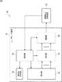
図1は、本発明の一実施の形態である車載システム1の構成例を示している。<1. Embodiment>
{Configuration example of in-vehicle system 1}
FIG. 1 shows a configuration example of an in-
車載システム1は、スイッチ11、車速センサ12、シフト位置検出器13、アクセルペダル検出器14、ブレーキペダル検出器15、衝突防止制御装置16、警報装置17、原動機制御装置18、及び、ブレーキ制御装置19を含むように構成される。 The in-
なお、以下、車載システム1が設けられている車両を他の車両と区別する必要がある場合、自車両と称する。さらに、以下、自車両の左右方向(車幅方向)と平行な方向を水平方向と称する。 Hereinafter, when it is necessary to distinguish a vehicle in which the in-
スイッチ11は、例えば、イグニッションスイッチ又はパワースイッチ等からなる。スイッチ11は、例えば、自車両の原動機(例えば、エンジンやモータ等)の始動や停止、及び、電装品への電源の供給モードの切り替えに用いられる。スイッチ11は、設定位置や操作内容を示す信号を衝突防止制御装置16の衝突防止演算装置32に供給する。 The
車速センサ12は、自車両の速度を検出し、検出結果を衝突防止制御装置16の衝突防止演算装置32に供給する。 The
シフト位置検出器13は、自車両のシフトレバー(不図示)又はセレクトレバー(不図示)のポジション(設定位置)を検出し、検出結果を衝突防止制御装置16の衝突防止演算装置32に供給する。 The
アクセルペダル検出器14は、自車両のアクセル開度を検出し、検出結果を衝突防止制御装置16の衝突防止演算装置32に供給する。 The
ブレーキペダル検出器15は、自車両のブレーキペダル(不図示)の踏込量を検出し、検出結果を衝突防止演算装置32に供給する。 The
衝突防止制御装置16は、自車両が周囲の物体に衝突することを防止する衝突防止機能の制御を行う。衝突防止制御装置16は、レーザレーダ装置31及び衝突防止演算装置32を含むように構成される。 The collision
レーザレーダ装置31は、自車両の前方を監視し、自車両の前方の物体の有無、物体の種類、物体までの距離、物体の方向、物体の相対速度等を検出する。また、レーザレーダ装置31は、検出結果に基づいて、自車両の発進、加速、運転者への警報等に関する指令を衝突防止演算装置32に行う。 The
なお、以下、レーザレーダ装置31により物体の検出が可能な領域を監視領域と称する。 Hereinafter, an area where an object can be detected by the
衝突防止演算装置32は、例えば、制御プログラムが組み込まれたECU(Electronic Control Unit)であり、マイクロコンピュータ、記憶素子、入出力インタフェース等により構成される。衝突防止演算装置32は、走行制御部41及び通知制御部42を含むように構成される。 The collision
走行制御部41は、レーザレーダ装置31からの指令に基づいて、原動機制御装置18及びブレーキ制御装置19を制御し、自車両の発進又は加速を抑制する。また、走行制御部41は、車速センサ12による車速の検出結果、及び、シフト位置検出器13によるシフトレバー又はセレクトレバーのポジションの検出結果等の外部からの情報に基づいて、自車両の移動方向を検出する。走行制御部41は、自車両の移動方向の検出結果をレーザレーダ装置31に供給する。 The
通知制御部42は、レーザレーダ装置31からの指令に基づいて、警報装置17による警報の制御を行う。 The
警報装置17は、例えば、カーナビゲーションシステムやインストルメントパネルに設けられているディスプレイ等の表示装置、インジケータランプ、LED(Light Emitting Diode)等の発光装置、ブザー等の音声出力装置等により構成される。 The
原動機制御装置18は、自車両の原動機(例えば、エンジン、モータ等)の制御を行う。例えば、原動機制御装置18は、自車両の原動機がエンジンである場合、エンジンのスロットル開度等を制御する。また、例えば、原動機制御装置18は、自車両の原動機がモータである場合、モータの回転数等を制御する。 The prime
ブレーキ制御装置19は、例えば、自車両のブレーキの動作の制御、及び、自動ブレーキの制御を行う。 The
{レーザレーダ装置31の構成例}
図2は、レーザレーダ装置31の構成例を示している。レーザレーダ装置31は、制御部61、測定光投光部62、受光部63、測定部64、及び、演算部65を含むように構成される。{Configuration example of laser radar device 31}
FIG. 2 shows a configuration example of the
制御部61は、衝突防止演算装置32からの指令や情報等に基づいて、レーザレーダ装置31の各部の制御を行う。 The
測定光投光部62は、物体の検出に用いるパルス状のレーザ光(レーザパルス)である測定光を監視領域に投光する。 The
受光部63は、測定光の反射光を受光し、水平方向のそれぞれ異なる方向からの反射光の強度(明るさ)を検出する。そして、受光部63は、各方向の反射光の強度に応じた電気信号である複数の受光信号を出力する。 The
測定部64は、受光部63から供給されるアナログの受光信号に基づいて、受光部63における反射光に対する受光値の測定を行い、測定した受光値を示すデジタルの受光信号を演算部65に供給する。 The
演算部65は、測定部64から供給される受光信号に基づいて、監視領域内の物体の有無、物体の種類、物体までの距離、物体の方向、物体の相対速度等の検出を行う。演算部65は、検出結果を制御部61に供給する。また、演算部65は、検出結果に基づいて、自車両の発進、加速、運転者への警報等に関する指令を衝突防止演算装置32に行う。 Based on the light reception signal supplied from the
{測定光投光部62の構成例}
図3は、レーザレーダ装置31の測定光投光部62の構成例を示している。測定光投光部62は、駆動回路101、発光素子102、及び、投光光学系103を含むように構成される。{Configuration example of measuring light projector 62}
FIG. 3 shows a configuration example of the measuring
駆動回路101は、制御部61の制御の下に、発光素子102の発光強度や発光タイミング等の制御を行う。 The
発光素子102は、例えば、レーザダイオードからなり、駆動回路101の制御の下に、測定光(レーザパルス)の発光を行う。発光素子102から発光された測定光は、レンズ等により構成される投光光学系103を介して、自車両の前方において水平方向(車幅方向)に放射状に広がる監視領域に投光される。 The
{受光部63の構成例}
図4は、レーザレーダ装置31の受光部63の構成例を示している。受光部63は、受光光学系201及び受光素子202−1乃至202−16を含むように構成される。{Configuration example of light receiving unit 63}
FIG. 4 shows a configuration example of the
なお、以下、受光素子202−1乃至202−16を個々に区別する必要がない場合、単に受光素子202と称する。 Hereinafter, the light receiving elements 202-1 to 202-16 are simply referred to as the light receiving elements 202 when it is not necessary to distinguish them individually.
受光光学系201は、レンズ等により構成され、光軸が車両の前後方向を向くように設置される。そして、受光光学系201は、監視領域内の物体等により反射された測定光の反射光が入射し、入射した反射光を各受光素子202の受光面に入射させる。 The light receiving
各受光素子202は、例えば、入射した光電荷をその光量に応じた電流値の受光信号に光電変換するフォトダイオードからなる。また、各受光素子202は、受光光学系201に入射した反射光が集光する位置において、受光光学系201の光軸に対して垂直、かつ、自車両の車幅方向に平行(すなわち、水平方向)に一列に並ぶように設けられている。そして、受光光学系201に入射した反射光は、受光光学系201への水平方向の入射角度に応じて、各受光素子202に振り分けられて入射する。従って、各受光素子202は、監視領域からの反射光のうち、水平方向においてそれぞれ異なる方向からの反射光を受光する。これにより、監視領域は水平方向の複数の方向における複数の領域(以下、検出領域と称する)に分割され、各受光素子202は、それぞれ対応する検出領域からの反射光を個別に受光する。そして、受光素子202は、受光した反射光をその受光量に応じた電流値の受光信号に光電変換し、得られた受光信号を測定部64に供給する。 Each light receiving element 202 is composed of, for example, a photodiode that photoelectrically converts incident photoelectric charges into a received light signal having a current value corresponding to the amount of light. Each light receiving element 202 is perpendicular to the optical axis of the light receiving
{監視領域及び検出領域の具体例}
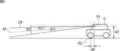
ここで、図5乃至図7を参照して、監視領域及び検出領域の具体例について説明する。図5は、レーザレーダ装置31が設けられた車両Cを横から見た場合の測定光の照射範囲を模式的に示している。図6は、車両Cを上から見た場合の各検出領域の位置を模式的に示している。図7は、受光部63を上から見た場合の各受光素子202と各検出領域との関係を模式的に示している。なお、図7では、図を分かりやすくするために、各検出領域からの反射光のうち受光光学系201のレンズの中央を通る光線のみを模式的に示している。{Specific examples of monitoring area and detection area}
Here, specific examples of the monitoring area and the detection area will be described with reference to FIGS. FIG. 5 schematically shows the irradiation range of the measurement light when the vehicle C provided with the
レーザレーダ装置31は、例えば、図5に示されるように、車両Cのフロントガラス(不図示)の内側(車内)であって、ルームミラー(不図示)の裏側に設置される。そして、レーザレーダ装置31の測定光投光部62から車両Cの前方に、水平方向及び上下方向(垂直方向)に放射状に広がるように測定光LBが投光される。 For example, as shown in FIG. 5, the
なお、以下、図5に示されるように、測定光LBの出射位置を位置P1とする。また、以下、位置P1の路面からの高さを高さh0とする。さらに、以下、車両Cの前輪の下端P2と位置P1との間の距離を距離d0とする。また、以下、測定光LBの垂直方向の視野角を角度θ1とし、測定光LBの視野軸A1の傾きを角度θ2とし、測定光LBの下端の傾きを角度θ3とする。 Hereinafter, as shown in FIG. 5, the emission position of the measurement light LB is defined as a position P1. Hereinafter, the height of the position P1 from the road surface is defined as a height h0. Further, hereinafter, a distance between the lower end P2 of the front wheel of the vehicle C and the position P1 is a distance d0. Further, hereinafter, the vertical viewing angle of the measuring light LB is defined as an angle θ1, the tilt of the viewing axis A1 of the measuring light LB is defined as an angle θ2, and the tilt of the lower end of the measuring light LB is defined as an angle θ3.
また、図7に示されるように、各受光素子202は、車両Cの進行方向に向かって右から受光素子202−1、202−2、202−3・・・の順に一列に並べられている。これに対して、図6に示されるように、レーザレーダ装置31の監視領域は、車両Cの前方に放射状に広がる検出領域A1乃至A16により構成され、各検出領域は、車両Cの進行方向に向かって左から検出領域A1、A2、A3・・・の順に並んでいる。例えば、受光素子202−1は、監視領域内の左端であって、車両Cの左前方の斜線で示される検出領域A1からの反射光を受光する。また、受光素子202−16は、監視領域内の右端であって、車両Cの右前方の斜線で示される検出領域A16からの反射光を受光する。さらに、受光素子202−8及び202−9は、監視領域の中央の網掛けで示される検出領域A8及びA9からの反射光を受光する。 7, the light receiving elements 202 are arranged in a line in the order of the light receiving elements 202-1, 202-2, 202-3,... From the right in the traveling direction of the vehicle C. . On the other hand, as shown in FIG. 6, the monitoring area of the
{測定部64の構成例}
図8は、レーザレーダ装置31の測定部64の構成例を示している。測定部64は、電流電圧変換部251、増幅部252、及び、サンプリング部253を含むように構成される。電流電圧変換部251は、トランス・インピーダンス・アンプ(TIA)261−1乃至261−16を含むように構成される。増幅部252は、プログラマブル・ゲイン・アンプ(PGA)262−1乃至262−16を含むように構成される。サンプリング部253は、A/Dコンバータ(ADC)263−1乃至263−16を含むように構成される。また、TIA261−i、PGA262−i及びADC263−i(i=1乃至16)は、それぞれ直列に接続されている。{Configuration example of measuring unit 64}
FIG. 8 shows a configuration example of the
なお、以下、TIA261−1乃至261−16、PGA262−1乃至262−16、及び、ADC263−1乃至263−16をそれぞれ個々に区別する必要がない場合、それぞれ単にTIA261、PGA262、及び、ADC263と称する。 Hereinafter, when it is not necessary to individually distinguish TIA 261-1 through 261-16, PGA 262-1 through 262-16, and ADC 263-1 through 263-16, TIA 261, PGA 262, and ADC 263 are simply Called.
各TIA261は、制御部61の制御の下に、受光素子202から供給される受光信号の電流−電圧変換を行う。すなわち、各TIA261は、入力された電流としての受光信号を電圧としての受光信号に変換するとともに、制御部61により設定されたゲインで変換後の受光信号の電圧を増幅する。そして、各TIA261は、増幅後の受光信号を後段のPGA262に供給する。 Each TIA 261 performs current-voltage conversion of the light reception signal supplied from the light receiving element 202 under the control of the
各PGA262は、制御部61の制御の下に、TIA261から供給される受光信号の電圧を、制御部61により設定されたゲインで増幅し、後段のADC263に供給する。 Each PGA 262 amplifies the voltage of the received light signal supplied from the TIA 261 with the gain set by the
各ADC263は、受光信号のA/D変換を行う。すなわち、各ADC263は、制御部61の制御の下に、PGA262から供給されるアナログの受光信号のサンプリングを所定のサンプリング間隔で行うことにより、各サンプリング時刻における受光値の測定を行う。そして、各ADC263は、受光値のサンプリング結果(測定結果)を示すデジタルの受光信号を演算部65に供給する。 Each ADC 263 performs A / D conversion of the received light signal. That is, each ADC 263 performs measurement of a light reception value at each sampling time by sampling an analog light reception signal supplied from the PGA 262 at a predetermined sampling interval under the control of the
{演算部65の構成例}
図9は、演算部65の機能の構成例を示している。演算部65は、検出部301、判別部302、及び、指令部303を含むように構成される。{Configuration example of calculation unit 65}
FIG. 9 shows a configuration example of the function of the
検出部301は、監視領域内の物体の検出を行う。検出部301は、ピーク検出部311及び物体検出部312を含むように構成される。 The
ピーク検出部311は、各ADC263から供給される受光信号に基づいて、各受光素子202の受光値のピーク検出を行う。これにより、測定光の反射光の強度の水平方向及び時間方向(距離方向)のピークが検出される。ピーク検出部311は、検出結果を物体検出部312に供給する。 The
物体検出部312は、受光値(反射光の強度)の水平方向及び時間方向(距離方向)の分布並びにピークの検出結果に基づいて、監視領域内の物体の有無、物体が存在する方向、物体までの距離、物体の方向、物体の相対速度等の検出を行う。物体検出部312は、検出結果を判別部302に供給する。また、物体検出部312は、検出領域毎の検出距離の検出結果を判別部302に供給する。 The
判別部302は、自車両の移動方向の検出結果を走行制御部41から取得する。判別部302は、物体検出部312により検出された物体までの検出距離、検出領域毎の検出距離、走行制御部41により検出された自車両の移動方向等に基づいて、物体検出部312により検出された物体の判別を行う。例えば、判別部302は、例えば、物体検出部312により検出された物体が坂の可能性があるか否か、及び、登坂可能な坂であるか否か等の判定を行う。ここで、坂とは、例えば、車両の通行用の道が設けられている坂道に限定されるものではなく、例えば、道が設けられていない坂も含む。判別部302は、物体の判別結果を含む物体の検出結果を制御部61及び指令部303に供給する。 The
指令部303は、判別部302から供給される物体の検出結果に応じて、自車両の発進、加速等に関する指令を走行制御部41に行う。また、指令部303は、判別部302から供給される物体の検出結果に応じて、運転者への警報等に関する指令を通知制御部42に行う。 The
{監視処理}
次に、図10のフローチャートを参照して、車載システム1により実行される発進時衝突防止制御処理について説明する。なお、この処理は、例えば、自車両の発進が可能な位置にスイッチ11が設定されたとき開始される。{Monitoring process}
Next, the start-time collision prevention control process executed by the in-
ステップS1において、レーザレーダ装置31は、監視を開始する。すなわち、レーザレーダ装置31は、以下の処理を開始することにより自車両の前方の監視領域内の監視を開始する。In step S1, the
駆動回路101は、制御部61の制御の下に、発光素子102からパルス状の測定光を出射させる。発光素子102から出射された測定光は、投光光学系103を介して監視領域全体に投光される。 The
各受光素子202は、受光光学系201を介して、測定光投光部62から投光された測定光に対する反射光のうち、それぞれ対応する方向の検出領域からの反射光を受光する。そして、各受光素子202は、受光した反射光をその受光量に応じた電気信号である受光信号に光電変換し、得られた受光信号を後段のTIA261に供給する。 Each light receiving element 202 receives the reflected light from the detection region in the corresponding direction among the reflected light with respect to the measuring light projected from the measuring
各TIA261は、制御部61の制御の下に、各受光素子202から供給された受光信号の電流−電圧変換を行うとともに、制御部61により設定されたゲインにより受光信号の電圧を増幅する。各TIA261は、増幅後の受光信号を後段のPGA262に供給する。 Each TIA 261 performs current-voltage conversion of the light reception signal supplied from each light receiving element 202 under the control of the
各PGA262は、制御部61の制御の下に、各TIA261から供給される受光信号の電圧を、制御部61により設定されたゲインで増幅し、後段のADC263に供給する。 Each PGA 262 amplifies the voltage of the received light signal supplied from each TIA 261 with the gain set by the
各ADC263は、制御部61の制御の下に、各PGA262から供給される受光信号のサンプリングを行い、受光信号をA/D変換する。そして、各ADC263は、各サンプリング時刻におけるサンプリング値(受光値)を示すデジタルの受光信号をピーク検出部311に供給する。 Each ADC 263 performs sampling of the light reception signal supplied from each PGA 262 under the control of the
ピーク検出部311は、受光素子202毎に受光値がピークとなるサンプリング時刻を検出する。すなわち、ピーク検出部311は、各受光素子202に対応する水平方向の検出領域毎に受光値の時間方向のピークを検出する。ピーク検出部311は、検出結果を物体検出部312に供給する。 The
物体検出部312は、例えば、測定光が投光されてから受光値がピークとなるまでの時間差に基づいて、各検出領域において測定光を反射する物体までの自車両からの距離(以下、検出距離と称する)を検出する。すなわち、物体検出部312は、監視領域内の各方向の物体までの検出距離を検出する。そして、物体検出部312は、今回の各検出領域における検出距離、及び、過去の各検出領域における検出距離等に基づいて、監視領域内の物体の有無、物体が存在する方向、物体までの距離、物体の方向、物体の相対速度等の検出を行う。 For example, the
ここで、例えば、1つの物体が複数の検出領域にわたって存在する場合、当該物体に対して検出領域毎に複数の検出距離が検出される。この場合、例えば、当該物体に対して検出された複数の検出距離の最小値又は平均値等が、当該物体までの検出距離として求められる。 Here, for example, when one object exists over a plurality of detection regions, a plurality of detection distances are detected for each detection region with respect to the object. In this case, for example, a minimum value or an average value of a plurality of detection distances detected for the object is obtained as a detection distance to the object.
物体検出部312は、監視領域内の物体の有無、物体が存在する方向、物体までの距離、物体の方向、物体の相対速度等の検出結果を判別部302に供給する。また、物体検出部312は、検出領域毎の検出距離の検出結果を判別部302に供給する。 The
なお、物体検出部312の物体検出方法には、任意の方法を採用することができる。また、物体検出部312が検出する物体には、例えば、他の車両、歩行者、道路付帯物、坂等が含まれる。 Note that any method can be employed as the object detection method of the
ステップS2において、判別部302は、物体検出部312からの最新の検出結果に基づいて、物体が検出されたか否かを判定する。物体が検出されたと判定された場合、処理はステップS3に進む。 In step S <b> 2, the
ステップS3において、判別部302は、物体までの検出距離が危険距離以内であるか否かを判定する。なお、危険距離とは、自車両が誤って急発進すると衝突するおそれがある距離のことである。例えば、危険距離は、自車両の加速性能等に基づいて設定される。そして、物体までの検出距離が危険距離以内であると判定された場合、処理はステップS4に進む。 In step S3, the
ステップS4において、判別部302は、物体までの検出距離が坂検出最短距離未満であるか否かを判定する。なお、坂検出最短距離とは、自車両が登坂可能な坂に対してレーザレーダ装置31により検出されると想定される最短距離のことである。 In step S4, the
ここで、図11を参照して、図5を参照して上述した車両Cの坂検出最短距離の算出方法の例について説明する。 Here, with reference to FIG. 11, an example of a method of calculating the hill detection shortest distance of the vehicle C described above with reference to FIG. 5 will be described.
車両Cが登坂可能な坂までの検出距離が最短になるのは、車両Cが登坂可能な坂のうち最も急勾配な坂S0に車両Cが最も接近したときである。このとき、図11の上の図に示されるように、車両Cの前輪の下端P2が、坂S0の下端にほぼ接した状態となる。 The shortest detection distance until the vehicle C can climb is when the vehicle C approaches the steepest slope S0 among the hills that the vehicle C can climb. At this time, as shown in the upper diagram of FIG. 11, the lower end P2 of the front wheel of the vehicle C is substantially in contact with the lower end of the slope S0.
なお、以下、坂S0の勾配角をγ0とする。また、以下、図11の上の図に示される状態において、坂S0と測定光LBの下端とが接する点を点P3とし、点P3の高さをhtとする。さらに、以下、この状態においてレーザレーダ装置31により検出される坂S0までの距離、すなわち、坂検出最短距離をLminとする。 Hereinafter, the slope angle of the slope S0 is γ0. Further, hereinafter, in the state shown in the upper diagram of FIG. 11, a point where the slope S0 and the lower end of the measuring light LB are in contact is defined as a point P3, and the height of the point P3 is defined as ht. Further, hereinafter, the distance to the slope S0 detected by the
図11の下の図は、点P1乃至点P3の位置関係を模式的に示している。この図より、以下の式(1)及び式(2)が成り立つ。 The lower diagram in FIG. 11 schematically shows the positional relationship between the points P1 to P3. From this figure, the following formulas (1) and (2) hold.
tanγ0=ht/(Lmin−d0) ・・・(1)
tanθ3=(h0−ht)/Lmin ・・・(2)tanγ0 = ht / (Lmin−d0) (1)
tan θ3 = (h0−ht) / Lmin (2)
式(1)より、高さhtは、次式(3)で表される。 From the formula (1), the height ht is expressed by the following formula (3).
ht=tanγ0×(Lmin−d0) ・・・(3) ht = tan γ0 × (Lmin−d0) (3)
そして、式(3)を式(2)に代入し、整理することにより、次式(4)に示されるように、坂検出最短距離Lminが求まる。 Then, by substituting Equation (3) into Equation (2) and rearranging, the shortest slope detection distance Lmin is obtained as shown in the following Equation (4).
Lmin=(h0+d0・tanγ0)/(tanγ0+tanθ3) ・・・(4) Lmin = (h0 + d0 · tan γ0) / (tan γ0 + tan θ3) (4)
例えば、h0=1.42m、d0=0.56m、θ3=7.0度であるとし、γ0を日本で施工可能な上り坂の最大勾配角である6.8度とした場合、坂検出最短距離Lminは、6.143mとなる。 For example, when h0 = 1.42 m, d0 = 0.56 m, θ3 = 7.0 degrees, and γ0 is 6.8 degrees, which is the maximum slope angle of an uphill that can be constructed in Japan, the shortest slope detection The distance Lmin is 6.143 m.
また、例えば、h0=1.42m、d0=0.56m、θ3=7.0度であるとし、γ0を一般車が登坂可能な最大勾配角である17.7度とした場合、坂検出最短距離Lminは、3.618mになる。ここで、一般車が登坂可能な最大勾配角である17.7度は、国土技術政策総合研究所発行の国総研資料第667号の「3.縦断勾配の限界に関する検討」に基づいて設定した値である。 For example, when h0 = 1.42 m, d0 = 0.56 m, and θ3 = 7.0 degrees, and γ0 is 17.7 degrees, which is the maximum gradient angle at which ordinary cars can climb, the shortest slope detection is possible. The distance Lmin is 3.618 m. Here, 17.7 degrees, the maximum slope angle that ordinary cars can climb, was set based on “3. Examination on the limits of longitudinal slope” in National Institute of Advanced Industrial Science and Technology No. 667 issued by National Institute for Land and Infrastructure Management. Value.
なお、実際の勾配角γ0は、例えば、排気量や重量等の要因に基づいて車種毎に設定される。 The actual gradient angle γ0 is set for each vehicle type based on factors such as the displacement and weight, for example.
また、図12の上の図は、図11の上の図と同様に、車両Cが坂S0に最も接近した状態を示しており、図12の下の図は、車両Cが坂S0を登り始めた状態を示している。この例に示されるように、車両Cが坂S0を登り始めると、レーザレーダ装置31の検出距離L1は、坂検出最短距離Lminより長くなる。従って、車両Cが登坂可能な坂までの検出距離が、坂検出最短距離Lmin未満になることはない。逆に、物体までの検出距離が坂検出最短距離Lmin未満である場合、その物体は、少なくとも車両Cが登坂可能な坂ではないと判定することができる。 The upper diagram of FIG. 12 shows a state in which the vehicle C is closest to the slope S0 as in the upper diagram of FIG. 11, and the lower diagram of FIG. It shows the state that started. As shown in this example, when the vehicle C starts to climb the slope S0, the detection distance L1 of the
図13及び図14は、物体までの検出距離が、坂検出最短距離Lmin未満となる例を示している。具体的には、図13は、車両Cが障害物401に接近し、レーザレーダ装置31の検出距離L2が、坂検出最短距離Lminより短くなっている状態を示している。図14は、車両Cが坂S0より急勾配な坂S2に接近し、レーザレーダ装置31の検出距離L3が、坂検出最短距離Lminより短くなっている状態を示している。 13 and 14 show an example in which the detection distance to the object is less than the shortest slope detection distance Lmin. Specifically, FIG. 13 shows a state in which the vehicle C approaches the
このように、車両Cが、障害物401に接近した場合だけでなく、坂S0より急勾配な坂S1に接近した場合にも、物体までの検出距離が坂検出最短距離未満となることがある。 Thus, not only when the vehicle C approaches the
そして、ステップS4において、物体までの検出距離が坂検出最短距離以上であると判定された場合、処理はステップS5に進む。 If it is determined in step S4 that the detection distance to the object is equal to or greater than the shortest slope detection distance, the process proceeds to step S5.
ステップS5において、判別部302は、検出された物体が坂の可能性があるか否かを判定する。具体的には、判別部302は、検出領域毎(受光素子202毎)の検出距離の水平方向(車幅方向)の変化に基づいて、検出された物体が坂の可能性があるか否かを判定する。 In step S5, the
図15は、自車両が、坂の前方において、坂の斜面に対してほぼ垂直な方向(坂が延びる方向にほぼ平行な方向)を向くように停車している場合の検出距離の水平方向の分布の例を示している。グラフの横軸は、自車両の正面方向を0度とした場合の水平方向の角度を示し、自車両に対して右方向の角度が正の値で示され、左方向の角度が負の値で示されている。グラフの縦軸は、各方向の検出距離を示している。 FIG. 15 shows the detection distance in the horizontal direction when the host vehicle is stopped so as to face a direction substantially perpendicular to the slope of the hill (a direction substantially parallel to the direction in which the hill extends) in front of the hill. An example of the distribution is shown. The horizontal axis of the graph shows the angle in the horizontal direction when the front direction of the host vehicle is 0 degree, the right angle with respect to the host vehicle is shown as a positive value, and the left direction angle is a negative value. It is shown in The vertical axis of the graph indicates the detection distance in each direction.
この例のように、自車両が前方の坂の斜面に対してほぼ垂直な方向を向くように停車している場合、水平方向の検出距離はほぼ一定になる。ただし、自車両の前方に車幅より広い範囲にわたり水平方向に広がる面を持つ物体(例えば、壁等)があり、自車両がその面に対してほぼ垂直な方向に向くように停車している場合も、水平方向の検出距離は、図15と同様に変化する。もちろん、この自車両の車幅より広い範囲にわたり水平方向に広がる面を持つ物体には、坂も含まれる。従って、判別部302は、水平方向の検出距離がほぼ一定であっても、前方の物体が坂であると確定することはできない。 As in this example, when the host vehicle is stopped so as to face a direction substantially perpendicular to the slope of the front slope, the detection distance in the horizontal direction is substantially constant. However, there is an object (for example, a wall) having a surface extending in the horizontal direction over a range wider than the vehicle width in front of the host vehicle, and the host vehicle is stopped so as to face in a direction substantially perpendicular to the surface. Also in this case, the detection distance in the horizontal direction changes as in FIG. Of course, an object having a surface extending in the horizontal direction over a range wider than the vehicle width of the host vehicle includes a slope. Therefore, the
図16は、自車両が、坂の前方において、坂の斜面に対してやや右斜め方向を向くように停車している場合の検出距離の水平方向の分布の例を示している。グラフの横軸及び縦軸は、図15と同様である。 FIG. 16 shows an example of the distribution in the horizontal direction of the detection distance when the host vehicle stops ahead of the hill so as to turn slightly to the right with respect to the slope of the hill. The horizontal and vertical axes of the graph are the same as in FIG.
この例のように、自車両が前方の坂の斜面に対してやや右斜め方向を向くように停車している場合、検出距離は、右に行くに従って徐々に長くなるようになだらかに変化する。また、この場合、検出距離は、理想的には水平方向の角度に対して線形に変化する。ただし、例えば、自車両の前方に車幅より広い範囲にわたり水平方向に広がる面を持つ物体があり、自車両がその面に対してやや右斜め方向を向くように停車している場合も、水平方向の検出距離は、図16と同様に変化する。従って、判別部302は、検出距離が水平方向になだらかに変化していても、前方の物体が坂であると確定することはできない。 As in this example, when the host vehicle is stopped so as to turn slightly to the right with respect to the slope of the front slope, the detection distance gradually changes so as to gradually increase toward the right. In this case, the detection distance ideally changes linearly with respect to the horizontal angle. However, for example, even when there is an object with a surface extending in the horizontal direction over a range wider than the vehicle width in front of the host vehicle, and the host vehicle is stopped so that it faces slightly to the right, the horizontal The direction detection distance changes in the same manner as in FIG. Accordingly, the
一方、自車両の前方に、車幅より広い範囲にわたり水平方向に広がる面を持つ物体とは異なる物体が存在する場合、検出領域毎の検出距離は、水平方向になだらかに変化しなくなる。 On the other hand, when an object different from an object having a surface extending in the horizontal direction over a range wider than the vehicle width exists in front of the host vehicle, the detection distance for each detection region does not change smoothly in the horizontal direction.
例えば、図17は、自車両が、坂の前方において、坂の斜面に対してやや右斜め方向を向くように停車している場合に、坂の途中に物体が存在するときの検出距離の水平方向の分布の例を示している。グラフの横軸及び縦軸は、図15と同様である。 For example, FIG. 17 shows a horizontal detection distance when an object is present in the middle of a hill when the host vehicle is stopped in front of the hill so as to turn slightly to the right. An example of direction distribution is shown. The horizontal and vertical axes of the graph are the same as in FIG.
この例のように、坂の途中に物体が存在する場合、物体が存在する方向の検出距離が急激に変化し、検出距離は、水平方向になだらかに変化しなくなる。なお、例えば、自車両が、車幅より広い壁の前方において、壁面に対してやや右斜め方向を向くように停車している場合に、壁面の一部に突起がある場合も、水平方向の検出距離は、図17と同様に変化する。 As in this example, when an object is present in the middle of a hill, the detection distance in the direction in which the object exists changes rapidly, and the detection distance does not change smoothly in the horizontal direction. In addition, for example, when the vehicle is parked in front of a wall wider than the vehicle width so as to face slightly to the right with respect to the wall surface, even when there is a protrusion on a part of the wall surface, The detection distance changes as in FIG.
図18は、自車両の前方左方向に大きな物体が存在する場合の検出距離の水平方向の分布の例を示している。グラフの横軸及び縦軸は、図15と同様である。 FIG. 18 shows an example of the horizontal distribution of the detection distance when a large object is present in the left front direction of the host vehicle. The horizontal and vertical axes of the graph are the same as in FIG.
この例のように、自車両の前方に大きな物体が存在する場合、物体が存在する方向の検出距離が急激に変化し、検出距離は、水平方向になだらかに変化しなくなる。 As in this example, when a large object is present in front of the host vehicle, the detection distance in the direction in which the object exists changes rapidly, and the detection distance does not change smoothly in the horizontal direction.
以上により、判別部302は、検出領域毎の検出距離が水平方向になだらかに変化している場合、物体検出部312により検出された物体が坂の可能性があると判定する。なお、検出領域毎の検出距離が水平方向になだらかに変化している場合には、図15に示されるように、水平方向の検出距離がほぼ一定の場合も含まれる。 As described above, the
ここで、図19を参照して、検出距離が水平方向になだらかに変化しているか否かの判定方法の例について説明する。図19は、検出領域毎の検出距離の例を示すグラフである。グラフの横軸は、検出領域の番号を示し、縦軸は各検出領域の検出距離を示している。 Here, with reference to FIG. 19, an example of a method for determining whether or not the detection distance is gently changing in the horizontal direction will be described. FIG. 19 is a graph illustrating an example of a detection distance for each detection region. The horizontal axis of the graph indicates the number of the detection area, and the vertical axis indicates the detection distance of each detection area.
例えば、判別部302は、図19に示されるように、検出領域毎の検出距離の最大値と最小値の差が所定の閾値Dth以内である場合、検出距離が水平方向になだらかに変化していると判定する。或いは、例えば、判別部302は、水平方向に隣接する各検出領域間の検出距離の差が全て所定の閾値以内である場合、検出距離が水平方向になだらかに変化していると判定する。 For example, as shown in FIG. 19, when the difference between the maximum value and the minimum value of the detection distance for each detection region is within a predetermined threshold Dth, the
また、例えば、判別部302は、統計的な手法を用いて、検出距離が水平方向になだらかに変化しているか否かを判定することも可能である。例えば、判別部302は、検出領域毎の検出距離の分散が所定の閾値以内である場合、検出距離が水平方向になだらかに変化していると判定する。 Further, for example, the
以上の判定方法により、自車両が前方の坂の斜面に対してほぼ垂直な方向を向くように停車している場合、判別部302は、検出距離が水平方向になだらかに変化していると確実に判定することができる。一方、自車両が前方の坂の斜面に対して斜め方向を向くように停車している場合、以上の判定方法では、判別部302が、検出距離が水平方向になだらかに変化していると判定できない場合が想定される。すなわち、自車両が坂の斜面に対して斜め方向を向く角度が大きくなるほど、図16を参照して上述した検出距離の水平方向の分布のグラフの傾きが大きくなる。そのため、例えば、検出領域毎の検出距離の最大値と最小値の差が閾値Dthを超え、検出距離が水平方向になだらかに変化していないと判定される場合が想定される。 According to the above determination method, when the host vehicle is stopped so as to face a direction substantially perpendicular to the slope of the hill ahead, the
そこで、例えば、判別部302は、水平方向に隣接する各検出領域間の検出距離の差について、さらに隣接する領域間毎に差分をとる。例えば、検出領域A1と検出領域A2の間の検出距離の差をD1、検出領域A2と検出領域A3の間の検出距離の差をD2、検出領域A3と検出領域A4の間の検出距離の差をD3とすると、判別部302は、差D1と差D2の差分値DD1、差D2と差D3の差分値DD2を算出する。そして、判別部302は、算出した検出距離の差の差分値に基づいて、検出距離が水平方向になめらかに変化しているか否かを判定する。 Therefore, for example, the
例えば、判別部302は、検出距離の差の差分値が全て所定の閾値以内である場合、検出距離が水平方向になだらかに変化していると判定する。或いは、例えば、判別部302は、検出距離の差の差分値の最大値と最小値の差が所定の閾値以内である場合、検出距離が水平方向になだらかに変化していると判定する。或いは、例えば、判別部302は、検出距離の差の差分値の分散が所定の閾値以内である場合、検出距離が水平方向になだらかに変化していると判定する。 For example, when all the difference values of the detection distances are within a predetermined threshold, the
上述したように、自車両が前方の坂の斜面に対して斜め方向を向くように停車している場合、検出距離は、理想的には水平方向の角度に対して線形に変化する。従って、検出距離の差の差分値は、誤差を加味したとしても、ほぼ一定になる。そこで、以上のように検出距離の差の差分値に基づいて判定処理を行うことにより、自車両が前方の坂の斜面に対して斜め方向を向くように停車していても、検出距離が水平方向になだらかに変化していると確実に判定されるようになる。 As described above, when the host vehicle is stopped so as to face an oblique direction with respect to the slope of the front slope, the detection distance ideally changes linearly with respect to the angle in the horizontal direction. Therefore, the difference value of the difference in the detection distance is almost constant even if an error is taken into account. Therefore, by performing the determination process based on the difference value of the detection distance as described above, the detection distance is horizontal even when the host vehicle is stopped so as to face an oblique direction with respect to the slope of the front hill. It is reliably determined that the direction is gradually changing.
そして、ステップS5において、判別部302は、検出領域毎の検出距離(監視領域内の各方向の検出距離)が水平方向になだらかに変化している場合、検出された物体が坂の可能性があると判定し、処理はステップS6に進む。 In step S5, when the detection distance for each detection area (the detection distance in each direction in the monitoring area) is gradually changing in the horizontal direction, the
ステップS6において、衝突防止制御装置16は、発進制限を行う。具体的には、判別部302は、自車両の前方に坂の可能性がある物体が検出されたことを指令部303に通知する。指令部303は、発進制限信号を衝突防止演算装置32に供給する。 In step S6, the collision
衝突防止演算装置32の走行制御部41は、アクセルペダル検出器14により検出されるアクセルペダルの踏込量に関わらず、自車両の加速を抑制するように原動機制御装置18を制御する。例えば、走行制御部41は、自車両の加速度が所定の制限値以上にならないように、アクセルペダルの踏込量に対するスロットル開度を制限する。或いは、例えば、走行制御部41は、自車両の加速度が所定の制限値以上にならないように、アクセルペダルの踏込量に対するモータの回転数を制限する。そして、走行制御部41は、制限したスロットル開度又はモータの回転数の指令を原動機制御装置18に与える。 The
このように自車両の加速が抑制されるため、自車両が急発進し、危険距離の範囲内にある前方の物体に衝突することが防止される。 Thus, since the acceleration of the own vehicle is suppressed, the own vehicle is prevented from suddenly starting and colliding with a front object within the dangerous distance range.
なお、このとき、後述するステップS8の処理で、自車両の前進が禁止されている場合、前進の禁止が解除された上で、発進制限が行われる。これは、例えば、坂の途中や壁の前に物体が存在し、検出された物体が坂の可能性がないと一旦判定された後、その物体が移動することにより、検出された物体が坂の可能性があると改めて判定された場合等が想定される。 At this time, if the forward movement of the host vehicle is prohibited in the process of step S8 described later, the start restriction is performed after the prohibition of forward movement is released. This is because, for example, an object exists in the middle of a hill or in front of a wall, and once it is determined that the detected object is not a hill, the detected object is moved to the hill. It is assumed that it is determined again that there is a possibility of this.
ステップS7において、判別部302は、検出された物体が登坂可能な坂であるか否かを判定する。 In step S7, the
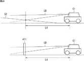
ここで、図20及び図21を参照して、前方の物体が登坂可能な坂であるか否かの判定方法の例について説明する。図20及び図21は、車両Cが坂S2に接近した場合と、壁411に接近した場合の検出距離の変化を比較した図である。 Here, with reference to FIG. 20 and FIG. 21, an example of a method for determining whether or not an object ahead is a hill that can be climbed will be described. 20 and 21 are diagrams comparing changes in the detection distance when the vehicle C approaches the slope S2 and when the vehicle C approaches the
図20は、車両Cが発進する前の状態の例を示している。上側の図においては、車両Cは、坂S2の前方に停車している。下側の図においては、車両Cは、壁411の前方に停車している。なお、車両Cから坂S2までの検出距離、及び、車両Cからの壁411までの検出距離とも、危険距離より短い距離L4であるものとする。また、坂S2の勾配角は、図11の坂S0の勾配角γ0より小さいものとする。 FIG. 20 shows an example of a state before the vehicle C starts. In the upper diagram, the vehicle C stops in front of the slope S2. In the lower diagram, the vehicle C stops in front of the
この例の場合、上述したように、ステップS5において、自車両の前方の物体(坂S2又は壁411)が坂の可能性があると判定され、発進制限が行われる。そして、車両Cは、前進を開始した後、徐行しながら坂S2及び壁411に接近する。 In the case of this example, as described above, in step S5, it is determined that there is a possibility that the object (slope S2 or wall 411) ahead of the host vehicle is a hill, and start restriction is performed. Then, after the vehicle C starts moving forward, the vehicle C approaches the slope S2 and the
図21は、図20に示される状態から、車両Cが同じ距離だけ坂S2及び壁411に接近した状態の例を示している。上側の図においては、車両Cは坂S2を登り始めた状態であり、車両Cから坂S2までの検出距離L5は、図20の検出距離L4より長くなる。一方、下側の図においては、車両Cから壁411までの検出距離L6は、図20の検出距離L4より短くなり、最終的に、坂検出最短距離Lminより短くなる。 FIG. 21 shows an example of a state in which the vehicle C approaches the slope S2 and the
例えば、走行制御部41は、車速センサ12による車速の検出結果、及び、シフト位置検出器13によるシフトレバー又はセレクトレバーのポジションの検出結果等に基づいて、自車両の移動方向を検出する。走行制御部41は、検出結果を判別部302に供給する。 For example, the
なお、自車両の移動方向の検出方法には、任意の方法を採用することができる。例えば、走行制御部41は、自車両の走行制御装置から供給される走行情報に基づいて、自車両の移動方向を検出するようにしてもよい。 An arbitrary method can be adopted as a method for detecting the moving direction of the host vehicle. For example, the traveling
判別部302は、自車両の移動方向が物体に接近する方向であるにも関わらず(自車両の物体の方向への移動が検出されているにも関わらず)、物体までの検出距離が、坂検出最短距離Lmin未満になる前に長くなった場合、検出された物体が登坂可能な坂であると判定する。一方、判別部302は、物体までの検出距離が坂検出最短距離Lmin未満になった場合、検出された物体は登坂可能な坂でないと判定する。 The
そして、ステップS7において、検出された物体が登坂可能な坂でないと判定された場合、処理はステップS8に進む。 If it is determined in step S7 that the detected object is not a hill that can be climbed, the process proceeds to step S8.
一方、ステップS5において、判別部302は、検出領域毎の検出距離が水平方向になだらかに変化していない場合、検出された物体が坂の可能性がないと判定し、ステップS6及びS7の処理はスキップされ、処理はステップS8に進む。 On the other hand, in step S5, when the detection distance for each detection region has not changed smoothly in the horizontal direction, the
また、ステップS4において、物体までの検出距離が坂検出最短距離未満であると判定された場合、すなわち、検出された物体が登坂可能な坂でない場合、ステップS5乃至S7の処理はスキップされ、処理はステップS8に進む。 If it is determined in step S4 that the detected distance to the object is less than the shortest slope detection distance, that is, if the detected object is not a hill that can be climbed, the processes in steps S5 to S7 are skipped and processed. Advances to step S8.
ステップS8において、衝突防止制御装置16は、前進を禁止する。具体的には、判別部302は、自車両の前方に衝突する可能性がある物体が検出されたことを指令部303に通知する。指令部303は、前進禁止信号を衝突防止演算装置32に供給する。 In step S8, the collision
衝突防止演算装置32の走行制御部41は、自車両が前進していない場合、シフトレバー又はセレクトレバーのポジション、及び、アクセルペダルの踏込量に関わらず、自車両が前方に発進しないように原動機制御装置18を制御する。また、走行制御部41は、自車両が前進している場合、まず自車両を停止させた後、自車両が前方に発進しないように原動機制御装置18を制御する。 When the host vehicle is not moving forward, the
なお、ここで、自車両の後方への発進については、必ずしも禁止する必要はない。以下、自車両の後方への発進を禁止しない場合について説明する。 Here, it is not always necessary to prohibit starting the vehicle backward. Hereinafter, a case where the vehicle is not prohibited from starting backward will be described.
その後、処理はステップS2に戻る。そして、ステップS2において、物体が検出されなかったと判定されるか、ステップS3において、物体までの検出距離が危険距離を超えていると判定されるか、ステップS7において、検出された物体が登坂可能な坂であると判定されるまで、ステップS2乃至S8の処理が繰り返し実行される。 Thereafter, the process returns to step S2. In step S2, it is determined that an object has not been detected. In step S3, it is determined that the detection distance to the object exceeds the danger distance. In step S7, the detected object can be climbed. Until it is determined that the road is a slope, the processes in steps S2 to S8 are repeatedly executed.
一方、ステップS7において、検出された物体が登坂可能な坂であると判定された場合、処理はステップS9に進む。 On the other hand, if it is determined in step S7 that the detected object is a hill that can be climbed, the process proceeds to step S9.
ステップS9において、衝突防止制御装置16は、発進制限を解除する。具体的には、判別部302は、自車両の前方に登坂可能な坂が検出されたことを指令部303に通知する。指令部303は、発進制限解除信号を衝突防止演算装置32に供給する。衝突防止演算装置32の走行制御部41は、発進制限を解除する。例えば、走行制御部41は、アクセルペダルの踏込量に対するスロットル開度又はモータの回転数の制限を解除する。これにより、自車両の通常走行が可能になる。 In step S9, the collision
その後、発進時衝突防止制御処理は終了する。 Thereafter, the start collision prevention control process ends.
一方、ステップS2において、物体が検出されなかったと判定されるか、ステップS3において、物体までの検出距離が危険距離を超えていると判定された場合、処理はステップS10に進む。 On the other hand, if it is determined in step S2 that no object has been detected, or if it is determined in step S3 that the detection distance to the object exceeds the danger distance, the process proceeds to step S10.
ステップS10において、指令部303は、前進が禁止されているか否かを判定する。具体的には、判別部302は、危険距離の範囲内に物体が存在しないことを指令部303に通知する。指令部303は、上述したステップS8の処理で自車両の前進を禁止した状態のまま解除していない場合、前進を禁止していると判定し、処理はステップS11に進む。 In step S10, the
これは、例えば、自車両の前方の危険距離以内に登坂可能な坂以外の物体が検出され、前進が禁止されている場合に、物体が移動したり、自車両が後方に移動したりして、危険距離以内に当該物体が存在しなくなった場合等が想定される。 This is because, for example, when an object other than a hill that can be climbed within a dangerous distance in front of the host vehicle is detected and the forward movement is prohibited, the object moves or the host vehicle moves backward. It is assumed that the object no longer exists within the dangerous distance.
ステップS11において、衝突防止制御装置16は、前進の禁止を解除する。具体的には、指令部303は、前進禁止解除信号を衝突防止演算装置32に供給する。衝突防止演算装置32の走行制御部41は、前進の禁止を解除する。これにより、自車両の通常走行が可能になる。 In step S11, the collision
その後、発進時衝突防止制御処理は終了する。 Thereafter, the start collision prevention control process ends.
一方、ステップS10において、前進が禁止されていないと判定された場合、ステップS11の処理はスキップされ、発進時衝突防止制御処理は終了する。 On the other hand, if it is determined in step S10 that the forward movement is not prohibited, the process of step S11 is skipped, and the start-time collision prevention control process ends.
以上のようにして、自車両が急発進し、前方の物体に衝突することが防止される。 As described above, it is possible to prevent the host vehicle from starting suddenly and colliding with an object ahead.
また、自車両の前方における坂の検出精度が向上し、登坂可能な坂が障害物と誤検出されことが防止される。これにより、自車両の前方が登坂可能な坂であるにも関わらず、自車両の発進が禁止されたり、加速が過度に抑制され、自車両が坂を登れなくなったりすることが防止される。 In addition, the accuracy of detecting the slope in front of the host vehicle is improved, and it is possible to prevent a slope that can be climbed from being erroneously detected as an obstacle. Accordingly, it is possible to prevent the start of the host vehicle from being prohibited or the acceleration of the host vehicle from being excessively suppressed and being unable to climb the hill even though the front of the host vehicle is a hill that can be climbed.
<2.変形例>
以下、上述した本発明の実施の形態の変形例について説明する。<2. Modification>
Hereinafter, modifications of the above-described embodiment of the present invention will be described.
{衝突防止制御装置の構成の変形例}
衝突防止制御装置の構成は、図1及び図2に示される例に限定されるものではなく、必要に応じて変更することが可能である。{Modification of configuration of collision prevention control device}
The configuration of the collision prevention control device is not limited to the example shown in FIGS. 1 and 2 and can be changed as necessary.
例えば、レーザレーダ装置31と衝突防止演算装置32を統合したり、機能の分担を変更したりすることが可能である。 For example, it is possible to integrate the
例えば、レーザレーダ装置31と衝突防止演算装置32を一体化するようにしてもよい。この場合、例えば、レーザレーダ装置31が、警報装置17、原動機制御装置18、及び、ブレーキ制御装置19を制御する。 For example, the
また、例えば、レーザレーダ装置31の指令部303の機能を、衝突防止演算装置32に設けるようにしてもよい。この場合、例えば、監視領域内の物体の有無、物体の種類、物体までの距離、物体の方向、物体の相対速度等の検出結果が、レーザレーダ装置31から衝突防止演算装置32に供給される。そして、衝突防止演算装置32が、レーザレーダ装置31から供給される検出結果に基づいて、発進制限又は前進の禁止を行うか否かを判定する。 Further, for example, the function of the
或いは、例えば、レーザレーダ装置31の判別部302及び指令部303の機能を、衝突防止演算装置32に設けるようにしてもよい。この場合、例えば、監視領域内の物体の有無、物体までの距離、物体の相対距離、物体の方向、検出領域毎の検出距離等の検出結果が、レーザレーダ装置31から衝突防止演算装置32に供給される。そして、衝突防止演算装置32が、検出された物体の種類の判別を行い、その結果に基づいて、発進制限又は前進の禁止を行うか否かを判定する。 Alternatively, for example, the functions of the
また、例えば、レーザレーダ装置31の制御部61と演算部65を統合したり、機能の分担を変更したりすることが可能である。 Further, for example, it is possible to integrate the
さらに、例えば、受光素子202、TIA261、PGA262、ADC263の数を、必要に応じて増減することが可能である。 Furthermore, for example, the number of light receiving elements 202, TIA 261, PGA 262, and ADC 263 can be increased or decreased as necessary.
{坂の可能性があるか否かの判定方法の変形例}
以上の説明では、検出領域毎の検出距離が水平方向になだらかに変化している場合に、検出された物体が坂の可能性があると判定する例を示した。{Variation of method for determining whether or not there is a possibility of slope}
In the above description, the example in which it is determined that the detected object is likely to be a slope when the detection distance for each detection region is gradually changing in the horizontal direction has been described.
しかし、例えば、道端にガードレールが存在する場合、ガードレールは路面より高い位置にあるため、ガードレールの検出距離は、路面の検出距離より若干短くなる。従って、坂の道端にガードレールが存在する場合、検出距離が水平方向になだらかに変化せず、坂の可能性がないと判定される可能性がある。しかし、図10のステップS3の処理で用いられる危険距離はせいぜい数m程度であり、危険距離の範囲内においてレーザ光の広がりは、せいぜい車幅程度である。そのため、危険距離の範囲内に坂が存在する場合、坂の道端にあるガードレールが検出される可能性は非常に低いと想定される。従って、危険距離の範囲内に坂があるにも関わらず、道端のガードレール等の物体により、坂の可能性がないと誤判定される可能性は非常に低いと考えられる。 However, for example, when a guard rail is present at the roadside, the guard rail is located at a higher position than the road surface, so the detection distance of the guard rail is slightly shorter than the detection distance of the road surface. Therefore, when there is a guardrail on the roadside of the slope, the detection distance may not be changed smoothly in the horizontal direction, and it may be determined that there is no possibility of a slope. However, the danger distance used in the process of step S3 in FIG. 10 is at most about several meters, and the spread of the laser beam within the danger distance is at most about the vehicle width. Therefore, when a slope exists within the dangerous distance range, it is assumed that the possibility of detecting a guardrail at the roadside of the slope is very low. Therefore, even though there is a slope within the dangerous distance range, it is considered very unlikely that an object such as a guardrail on the roadside will erroneously determine that there is no possibility of a slope.
ただし、例えば、道端の物体による誤判定をより確実に防止する対策を施すようにしてもよい。例えば、判別部302が、監視領域の左右の端部の所定の範囲を除いた範囲内において、検出距離が水平方向になだらかに変化している場合に、坂の可能性があると判定するようにしてもよい。或いは、例えば、判別部302が、監視領域の左端及び右端の少なくとも一方において、ガードレールの高さに相当する距離だけ検出距離が短く、他の範囲において、検出領域が水平方向になだらかに変化している場合に、道端にガードレールが設置された坂であると判定するようにしてもよい。 However, for example, a measure for more reliably preventing erroneous determination due to a roadside object may be taken. For example, the
{その他の変形例}
また、例えば、発進制限や前進の禁止を行う場合に、レーザレーダ装置31の指令部303が、運転者への警報を通知制御部42に指令するようにしてもよい。そして、通知制御部42が、運転者への警報を警報装置17に実行させるようにしてもよい。例えば、通知制御部42が、ディスプレイに警告画面を表示させたり、インジケータランプを点灯又は点滅させたり、警告音やブザー等を鳴らしたりして、運転者への警報を行うようにしてもよい。{Other variations}
Further, for example, when starting restriction or prohibiting forward movement, the
{本発明の適用範囲等について}
本発明は、上述した例以外にも、車両に設けられ、所定の監視方向に測定光を投光し、測定光の反射光の強度に基づいて物体の検出を行う装置やシステムに適用することができる。{About the scope of application of the present invention}
In addition to the examples described above, the present invention is applied to an apparatus or system that is provided in a vehicle, projects measurement light in a predetermined monitoring direction, and detects an object based on the intensity of reflected light of the measurement light. Can do.
例えば、本発明は、測定光を監視方向に同時に投光し、複数の受光素子により反射光を同時に受光する形式のレーザレーダ装置だけでなく、測定光を水平方向に走査しながら反射光を受光する走査型のレーザレーダ装置を用いる場合にも適用することができる。 For example, the present invention receives not only a laser radar device of a type that simultaneously projects measurement light in the monitoring direction and simultaneously receives reflected light by a plurality of light receiving elements, but also receives the reflected light while scanning the measurement light in the horizontal direction. The present invention can also be applied to the case of using a scanning type laser radar device.
図22は、走査型のレーザレーダ装置501の構成例を示している。レーザレーダ装置501は、制御部511、駆動回路512、スキャナ513、走査位置検出部514、測定部515、及び、演算部516を含むように構成される。スキャナ513は、発光素子521、投光レンズ522、受光レンズ523、及び、受光素子524を含むように構成される。 FIG. 22 shows a configuration example of a scanning
駆動回路512は、制御部511の制御の下に、発光素子521の発光強度や発光タイミング等の制御を行う。 The
発光素子521は、例えば、レーザダイオードからなり、駆動回路512の制御の下に、測定光(レーザパルス)の発光を行う。発光素子521から発光された測定光は、投光レンズ522を介して、自車両の前方に投光される。このとき、スキャナ513は、制御部511の制御の下に、測定光を監視領域内において水平方向に走査する。 The
走査位置検出部514は、スキャナ513における測定光の水平方向の走査位置を検出し、検出結果を制御部511及び演算部516に供給する。 The scanning
受光素子524は、例えば、フォトダイオードからなる。受光素子524は、受光レンズ523を介して、測定光の反射光を受光する。受光素子524は、受光した反射光をその受光量に応じた電流値の受光信号に光電変換し、得られた受光信号を測定部515に供給する。 The
測定部515は、図8の測定部64と同様に、受光素子524から供給されるアナログの受光信号に基づいて、反射光に対する受光値の測定を行い、測定した受光値を示すデジタルの受光信号を演算部516に供給する。なお、受光素子524が1つのみなので、測定部515は、図8の測定部64と異なり、TIA、PGA及びADC(いずれも不図示)は、それぞれ1つずつ設けられる。 Similar to the
演算部516は、図9の演算部65と同様に、測定部515から供給される受光信号に基づいて、監視領域内の物体の有無、物体の種類、物体までの距離、物体の方向、物体の相対速度等の検出を行う。演算部516は、検出結果を制御部511に供給する。また、演算部516は、検出結果に基づいて、自車両の発進、加速、運転者への警報等に関する指令を衝突防止演算装置32に行う。 Similar to the
また、本発明は、レーザ以外の測定光やミリ波等を用いたレーダ装置を用いる場合にも適用することが可能である。 The present invention can also be applied to the case where a radar apparatus using measurement light other than laser, millimeter wave, or the like is used.
さらに、以上の説明では、車両が前方に進む場合を例に挙げて説明したが、本発明は、車両が後方に進む場合にも適用することができる。例えば、車両の後方への発進時も同様に、図10を参照して上述した処理と同様の処理により、車両の後方を監視して、後方の物体への衝突を防止するとともに、後方の坂を登れるようにすることができる。 Furthermore, in the above description, the case where the vehicle travels forward has been described as an example, but the present invention can also be applied to the case where the vehicle travels backward. For example, when the vehicle starts to move backward, the vehicle is monitored in the same manner as described above with reference to FIG. 10 to prevent the vehicle from colliding with an object behind the vehicle and Can be climbed.
また、本発明を適用する車両の種類は、特に限定されるものではない。例えば、本発明は、二輪車、三輪トラック、小型トラック、小型乗用車、大型乗用車、大型バス、大型トラック、大型特殊車、小型特殊車等の車両に適用することができる。 The type of vehicle to which the present invention is applied is not particularly limited. For example, the present invention can be applied to vehicles such as motorcycles, three-wheel trucks, small trucks, small passenger cars, large passenger cars, large buses, large trucks, large special vehicles, and small special vehicles.
{コンピュータの構成例}
なお、上述した一連の処理は、ハードウエアにより実行することもできるし、ソフトウエアにより実行することもできる。一連の処理をソフトウエアにより実行する場合には、そのソフトウエアを構成するプログラムが、コンピュータにインストールされる。ここで、コンピュータには、専用のハードウエアに組み込まれているコンピュータや、各種のプログラムをインストールすることで、各種の機能を実行することが可能な、例えば汎用のパーソナルコンピュータなどが含まれる。{Example of computer configuration}
The series of processes described above can be executed by hardware or can be executed by software. When a series of processing is executed by software, a program constituting the software is installed in the computer. Here, the computer includes, for example, a general-purpose personal computer capable of executing various functions by installing various programs by installing a computer incorporated in dedicated hardware.
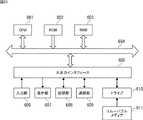
図23は、上述した一連の処理をプログラムにより実行するコンピュータのハードウエアの構成例を示すブロック図である。 FIG. 23 is a block diagram illustrating a configuration example of hardware of a computer that executes the above-described series of processing by a program.
コンピュータにおいて、CPU(Central Processing Unit)601,ROM(Read Only Memory)602,RAM(Random Access Memory)603は、バス604により相互に接続されている。 In a computer, a CPU (Central Processing Unit) 601, a ROM (Read Only Memory) 602, and a RAM (Random Access Memory) 603 are connected to each other by a
バス604には、さらに、入出力インタフェース605が接続されている。入出力インタフェース605には、入力部606、出力部607、記憶部608、通信部609、及びドライブ610が接続されている。 An input /
入力部606は、キーボード、マウス、マイクロフォンなどよりなる。出力部607は、ディスプレイ、スピーカなどよりなる。記憶部608は、ハードディスクや不揮発性のメモリなどよりなる。通信部609は、ネットワークインタフェースなどよりなる。ドライブ610は、磁気ディスク、光ディスク、光磁気ディスク、又は半導体メモリなどのリムーバブルメディア611を駆動する。 The
以上のように構成されるコンピュータでは、CPU601が、例えば、記憶部608に記憶されているプログラムを、入出力インタフェース605及びバス604を介して、RAM603にロードして実行することにより、上述した一連の処理が行われる。 In the computer configured as described above, the
コンピュータ(CPU601)が実行するプログラムは、例えば、パッケージメディア等としてのリムーバブルメディア611に記録して提供することができる。また、プログラムは、ローカルエリアネットワーク、インターネット、デジタル衛星放送といった、有線または無線の伝送媒体を介して提供することができる。 The program executed by the computer (CPU 601) can be provided by being recorded on a removable medium 611 as a package medium, for example. The program can be provided via a wired or wireless transmission medium such as a local area network, the Internet, or digital satellite broadcasting.
コンピュータでは、プログラムは、リムーバブルメディア611をドライブ610に装着することにより、入出力インタフェース605を介して、記憶部608にインストールすることができる。また、プログラムは、有線または無線の伝送媒体を介して、通信部609で受信し、記憶部608にインストールすることができる。その他、プログラムは、ROM602や記憶部608に、あらかじめインストールしておくことができる。 In the computer, the program can be installed in the
なお、コンピュータが実行するプログラムは、本明細書で説明する順序に沿って時系列に処理が行われるプログラムであっても良いし、並列に、あるいは呼び出しが行われたとき等の必要なタイミングで処理が行われるプログラムであっても良い。 The program executed by the computer may be a program that is processed in time series in the order described in this specification, or in parallel or at a necessary timing such as when a call is made. It may be a program for processing.
また、本発明の実施の形態は、上述した実施の形態に限定されるものではなく、本発明の要旨を逸脱しない範囲において種々の変更が可能である。 The embodiments of the present invention are not limited to the above-described embodiments, and various modifications can be made without departing from the scope of the present invention.
1 車載システム
11 スイッチ
12 車速センサ
13 シフト位置検出器
14 アクセルペダル検出器
15 ブレーキペダル検出器
16 衝突防止制御装置
18 原動機制御装置
19 ブレーキ制御装置
31 レーザレーダ装置
32 衝突防止演算装置
41 走行制御部
61 制御部
62 測定光投光部
63 受光部
64 測定部
65 演算部
102 発光素子
202−1乃至202−16 受光素子
301 検出部
302 判別部
303 指令部
311 ピーク検出部
312 物体検出部
501 レーザレーダ装置
511 制御部
512 駆動回路
513 スキャナ
514 走査位置検出部
515 測定部
516 演算部
521 発光素子
524 受光素子DESCRIPTION OF
Claims (7)
Translated fromJapanese前記進行方向において前記車両の車幅方向に放射状に広がる領域である監視領域内に測定光を投光する投光部と、
前記監視領域内の複数の方向からの前記測定光の反射光を受光し、各方向の前記反射光の強度に応じた受光信号を出力する受光部と、
前記測定光が投光されてから前記反射光を受光するまでの時間差に基づいて、前記監視領域内の各方向の物体までの距離を検出する検出部と、
前記検出部により検出された物体である検出物体の判別を行う判別部と
を備え、
前記判別部は、前記検出物体までの検出距離が、前記車両が登坂可能な最大勾配の坂に対して検出されると想定される最短距離未満である場合、前記検出物体が登坂可能な坂でないと判定する
物体検出装置。In an object detection apparatus that is mounted on a vehicle and detects an object in the traveling direction of the vehicle,
A light projecting unit that projects measurement light into a monitoring region that is a region that spreads radially in the vehicle width direction of the vehicle in the traveling direction;
A light receiving unit that receives reflected light of the measurement light from a plurality of directions in the monitoring region, and outputs a light reception signal according to the intensity of the reflected light in each direction;
A detection unit that detects a distance to an object in each direction in the monitoring area based on a time difference from when the measurement light is projected to when the reflected light is received;
A discrimination unit that discriminates a detected object that is an object detected by the detection unit,
Whenthe detection distance to the detection object is less than the shortest distance that is assumed to be detected with respect to a hill having a maximum gradient that the vehicle can climb , the determination unit isnot a hill on which the detection object can be climbed. An object detection devicethat determines that
請求項1に記載の物体検出装置。The object detection apparatus according to claim 1.
請求項2に記載の物体検出装置。The determination unit determines that the detected object may be a slope when the change in the vehicle width direction of the detection distance in each direction in the monitoring area is gentle, and determines each direction in the monitoring area. The object detection device according to claim2 , wherein when the change in the vehicle width direction of the detection distance is not gentle, it is determined that there is no possibility that the detected object is a slope.
請求項3に記載の物体検出装置。The determination unit is a case where a change in the vehicle width direction of the detection distance in each direction in the monitoring area is gentle, and movement of the vehicle in the direction of the detection object is detected based on information from the outside. The object detection device according to claim3 , wherein the detection object is determined to be a slope when the detection distance to the detection object becomes long.
前記受光部は、前記車幅方向に並べられた複数の受光素子を備え、
各前記受光素子は、前記監視領域内の各方向からの前記反射光をそれぞれ受光し、受光した前記反射光の強度に応じた受光信号を出力する
請求項1に記載の物体検出装置。The light projecting unit projects the measurement light so as to spread radially in the monitoring area,
The light receiving unit includes a plurality of light receiving elements arranged in the vehicle width direction,
The object detection apparatus according to claim 1, wherein each of the light receiving elements receives the reflected light from each direction in the monitoring region, and outputs a light reception signal corresponding to the intensity of the received reflected light.
請求項1に記載の物体検出装置。The object detection device according to claim 1, wherein the light projecting unit scans the measurement light in the vehicle width direction within the monitoring region.
前記車両の進行方向において車幅方向に放射状に広がる領域である監視領域内に測定光を投光する投光部と、
前記監視領域内の複数の方向からの前記測定光の反射光を受光し、各方向の前記反射光の強度に応じた受光信号を出力する受光部と、
前記測定光が投光されてから前記反射光を受光するまでの時間差に基づいて、前記監視領域内の各方向の物体までの距離を検出する検出部と、
前記車両の走行を制御する走行制御部と
を備え、
前記走行制御部は、前記検出部により検出された物体である検出物体までの検出距離が、前記車両が登坂可能な最大勾配の坂に対して検出されると想定される最短距離未満である場合、前記車両の前記進行方向への走行を禁止する制御を行う
車両用衝突防止制御装置。A collision prevention control device for a vehicle,
A light projecting unit that projects measurement light into a monitoring region that is a region that spreads radially in the vehicle width direction in the traveling direction of the vehicle;
A light receiving unit that receives reflected light of the measurement light from a plurality of directions in the monitoring region, and outputs a light reception signal according to the intensity of the reflected light in each direction;
A detection unit that detects a distance to an object in each direction in the monitoring area based on a time difference from when the measurement light is projected to when the reflected light is received;
A travel control unit for controlling the travel of the vehicle,
The travel control unit is configured such that a detection distance to a detection object that is an object detected by the detection unit is less than a shortest distance that is assumed to be detected with respect to a slope having a maximum gradient that the vehicle can climb. A vehicle collision prevention control device that performs control for prohibiting the vehicle from traveling in the traveling direction.
Priority Applications (4)
| Application Number | Priority Date | Filing Date | Title |
|---|---|---|---|
| JP2015000639AJP6270746B2 (en) | 2015-01-06 | 2015-01-06 | Object detection device and vehicle collision prevention control device |
| KR1020150187087AKR20160084804A (en) | 2015-01-06 | 2015-12-28 | Object detecting apparatus and vehicle collision avoidance control apparatus |
| US14/989,503US9945951B2 (en) | 2015-01-06 | 2016-01-06 | Object detecting apparatus and vehicle collision avoidance control apparatus |
| DE102016200067.5ADE102016200067A1 (en) | 2015-01-06 | 2016-01-06 | OBJEKTERMITTLUNGSVORRICHTUNG AND VEHICLE IMPACT AVOIDANCE CONTROL DEVICE |
Applications Claiming Priority (1)
| Application Number | Priority Date | Filing Date | Title |
|---|---|---|---|
| JP2015000639AJP6270746B2 (en) | 2015-01-06 | 2015-01-06 | Object detection device and vehicle collision prevention control device |
Publications (2)
| Publication Number | Publication Date |
|---|---|
| JP2016125925A JP2016125925A (en) | 2016-07-11 |
| JP6270746B2true JP6270746B2 (en) | 2018-01-31 |
Family
ID=56133228
Family Applications (1)
| Application Number | Title | Priority Date | Filing Date |
|---|---|---|---|
| JP2015000639AExpired - Fee RelatedJP6270746B2 (en) | 2015-01-06 | 2015-01-06 | Object detection device and vehicle collision prevention control device |
Country Status (4)
| Country | Link |
|---|---|
| US (1) | US9945951B2 (en) |
| JP (1) | JP6270746B2 (en) |
| KR (1) | KR20160084804A (en) |
| DE (1) | DE102016200067A1 (en) |
Families Citing this family (11)
| Publication number | Priority date | Publication date | Assignee | Title |
|---|---|---|---|---|
| WO2018047232A1 (en)* | 2016-09-06 | 2018-03-15 | マツダ株式会社 | Vehicle control device |
| US10351129B2 (en)* | 2017-01-13 | 2019-07-16 | Ford Global Technologies, Llc | Collision mitigation and avoidance |
| JP6332491B1 (en)* | 2017-02-13 | 2018-05-30 | オムロン株式会社 | LASER LIGHTING DEVICE AND PERSONAL MONITORING SENSOR HAVING THE SAME |
| WO2019031137A1 (en)* | 2017-08-07 | 2019-02-14 | 日立オートモティブシステムズ株式会社 | Roadside object detection device, roadside object detection method, and roadside object detection system |
| CN107672599B (en)* | 2017-09-06 | 2020-09-22 | 北京汽车集团越野车有限公司 | Radar system control method and device and automobile |
| DE102017220397A1 (en) | 2017-11-15 | 2019-05-16 | Osram Gmbh | DISTANCE MEASURING DEVICE |
| WO2020017393A1 (en)* | 2018-07-20 | 2020-01-23 | キヤノン株式会社 | Optical system, illumination device equipped with optical system, and range finder |
| US11328605B2 (en)* | 2019-03-26 | 2022-05-10 | Toyota Jidosha Kabushiki Kaisha | Adjustable blind spot monitor |
| CN110406489B (en)* | 2019-07-29 | 2021-05-25 | 江铃汽车股份有限公司 | Vehicle-mounted radar alarm display method and system and vehicle-mounted terminal |
| CN111257903B (en)* | 2020-01-09 | 2022-08-09 | 广州微牌智能科技有限公司 | Vehicle positioning method and device, computer equipment and storage medium |
| JP7419085B2 (en) | 2020-01-29 | 2024-01-22 | 本田技研工業株式会社 | Recognition device, recognition system, method, and program |
Family Cites Families (14)
| Publication number | Priority date | Publication date | Assignee | Title |
|---|---|---|---|---|
| JPH05124453A (en) | 1991-11-08 | 1993-05-21 | Jatco Corp | Running control device |
| JPH0735862A (en)* | 1993-07-20 | 1995-02-07 | Komatsu Ltd | Obstacle detection device for traveling vehicle |
| US5714928A (en) | 1992-12-18 | 1998-02-03 | Kabushiki Kaisha Komatsu Seisakusho | System for preventing collision for vehicle |
| JP4197209B2 (en)* | 1999-05-21 | 2008-12-17 | 株式会社小松製作所 | Unmanned vehicle traveling system |
| JP2004280489A (en) | 2003-03-17 | 2004-10-07 | Hitachi Ltd | Vehicle collision prevention control device |
| JP2008140013A (en) | 2006-11-30 | 2008-06-19 | Denso Corp | Obstacle detecting device |
| US8812226B2 (en)* | 2009-01-26 | 2014-08-19 | GM Global Technology Operations LLC | Multiobject fusion module for collision preparation system |
| KR100899820B1 (en)* | 2009-03-03 | 2009-05-27 | 국방과학연구소 | Ground / obstacle discrimination device and method for autonomous moving vehicle |
| JP5603625B2 (en)* | 2010-03-24 | 2014-10-08 | 本田技研工業株式会社 | Object detection device |
| JP5267592B2 (en)* | 2010-04-09 | 2013-08-21 | 株式会社デンソー | Object recognition device |
| US8260539B2 (en)* | 2010-05-12 | 2012-09-04 | GM Global Technology Operations LLC | Object and vehicle detection and tracking using 3-D laser rangefinder |
| JP2012192862A (en)* | 2011-03-17 | 2012-10-11 | Toyota Motor Corp | Vehicle controller |
| JP6128979B2 (en) | 2013-06-14 | 2017-05-17 | 株式会社クボタ | Farm work vehicle |
| US8825260B1 (en)* | 2013-07-23 | 2014-09-02 | Google Inc. | Object and ground segmentation from a sparse one-dimensional range data |
- 2015
- 2015-01-06JPJP2015000639Apatent/JP6270746B2/ennot_activeExpired - Fee Related
- 2015-12-28KRKR1020150187087Apatent/KR20160084804A/ennot_activeWithdrawn
- 2016
- 2016-01-06DEDE102016200067.5Apatent/DE102016200067A1/ennot_activeWithdrawn
- 2016-01-06USUS14/989,503patent/US9945951B2/ennot_activeExpired - Fee Related
Also Published As
| Publication number | Publication date |
|---|---|
| US20160195615A1 (en) | 2016-07-07 |
| DE102016200067A1 (en) | 2016-07-07 |
| KR20160084804A (en) | 2016-07-14 |
| JP2016125925A (en) | 2016-07-11 |
| US9945951B2 (en) | 2018-04-17 |
Similar Documents
| Publication | Publication Date | Title |
|---|---|---|
| JP6270746B2 (en) | Object detection device and vehicle collision prevention control device | |
| JP5387531B2 (en) | Driving support device | |
| US9157998B2 (en) | Laser radar device placed on glass surface of vehicle | |
| KR101071362B1 (en) | Vehicle object recognition system and operation method | |
| US9827956B2 (en) | Method and device for detecting a braking situation | |
| US9751528B2 (en) | In-vehicle control device | |
| US8638205B2 (en) | Device for preventing a collision of a pivoting element of a vehicle | |
| US20140293264A1 (en) | Laser radar device | |
| JP6320050B2 (en) | Laser radar equipment | |
| KR20200023691A (en) | Appartus and method for driving control of vehicle | |
| CN109094567B (en) | Automobile safety protection method and device | |
| JP4274028B2 (en) | Radar equipment for vehicles | |
| KR101500162B1 (en) | Braking Control System for Vehicle and Method thereof | |
| JP2010249668A (en) | Vehicle object detection device | |
| JP2008014722A (en) | Radar equipment | |
| KR20140049136A (en) | Parking assist apparatus and parking assist method and parking assist system using the same | |
| JP2019086402A (en) | Vehicle Obstacle Detection Device | |
| JP5494729B2 (en) | Approach notification device | |
| KR101316306B1 (en) | Smart-cruise-control-system and method for controlling the same | |
| JP2016048179A (en) | Laser radar device and object detection method | |
| JP2004125636A (en) | On-vehicle laser radar device | |
| CN117622208A (en) | Vehicle control device, vehicle control method and computer program for vehicle control | |
| JP6315584B2 (en) | Object detection system | |
| JP6576254B2 (en) | Optical radar device | |
| JP4395798B2 (en) | Radar equipment |
Legal Events
| Date | Code | Title | Description |
|---|---|---|---|
| A621 | Written request for application examination | Free format text:JAPANESE INTERMEDIATE CODE: A621 Effective date:20161207 | |
| A977 | Report on retrieval | Free format text:JAPANESE INTERMEDIATE CODE: A971007 Effective date:20171020 | |
| A131 | Notification of reasons for refusal | Free format text:JAPANESE INTERMEDIATE CODE: A131 Effective date:20171031 | |
| A521 | Request for written amendment filed | Free format text:JAPANESE INTERMEDIATE CODE: A523 Effective date:20171127 | |
| TRDD | Decision of grant or rejection written | ||
| A01 | Written decision to grant a patent or to grant a registration (utility model) | Free format text:JAPANESE INTERMEDIATE CODE: A01 Effective date:20171226 | |
| A61 | First payment of annual fees (during grant procedure) | Free format text:JAPANESE INTERMEDIATE CODE: A61 Effective date:20171226 | |
| R150 | Certificate of patent or registration of utility model | Ref document number:6270746 Country of ref document:JP Free format text:JAPANESE INTERMEDIATE CODE: R150 | |
| R250 | Receipt of annual fees | Free format text:JAPANESE INTERMEDIATE CODE: R250 | |
| R250 | Receipt of annual fees | Free format text:JAPANESE INTERMEDIATE CODE: R250 | |
| LAPS | Cancellation because of no payment of annual fees |