JP6269947B2 - Adhesive tape cartridge - Google Patents
Adhesive tape cartridgeDownload PDFInfo
- Publication number
- JP6269947B2 JP6269947B2JP2014080959AJP2014080959AJP6269947B2JP 6269947 B2JP6269947 B2JP 6269947B2JP 2014080959 AJP2014080959 AJP 2014080959AJP 2014080959 AJP2014080959 AJP 2014080959AJP 6269947 B2JP6269947 B2JP 6269947B2
- Authority
- JP
- Japan
- Prior art keywords
- tape
- printed
- substrate
- adhesive
- layer
- Prior art date
- Legal status (The legal status is an assumption and is not a legal conclusion. Google has not performed a legal analysis and makes no representation as to the accuracy of the status listed.)
- Expired - Fee Related
Links
Images


Landscapes
- Printers Characterized By Their Purpose (AREA)
- Handling Of Continuous Sheets Of Paper (AREA)
- Collation Of Sheets And Webs (AREA)
Description
Translated fromJapanese 本発明は、被着体に対し貼り付けて使用される印字済み粘着テープを供給するための、粘着テープカートリッジに関する。
The present invention, for supplying the adhesive tape to be used pasted to anadherend, toviscous adhesive tape cartridge.
従来、被着体に対し貼り付けて使用される印字済み粘着テープが知られている(例えば、特許文献1参照)。この印字済み粘着テープ(テープ)は、その厚さ方向の一方側の面(裏面)に、貼り付け用粘着層(粘着層)を有しており、その厚さ方向の他方側の面(表面)には、印字(ガイドマーク)が形成されている。そして、この従来技術においては、上記印字済み粘着テープがその厚さ方向の一方側の面(粘着面)を内側にして円筒状の芯に巻装されることにより、印字済み粘着テープロール(巻装テープ)として生成されている。 Conventionally, a printed adhesive tape that is used by being attached to an adherend is known (see, for example, Patent Document 1). This printed adhesive tape (tape) has a sticking adhesive layer (adhesive layer) on one surface (back surface) in the thickness direction, and the other surface (surface) in the thickness direction. ) Is printed (guide marks). In this prior art, the printed adhesive tape is wound around a cylindrical core with the one surface in the thickness direction (adhesive surface) facing inside, whereby a printed adhesive tape roll (wound) Tape).
ユーザは、所望の長さの印字済み粘着テープを(当該印字済み粘着テープに備えられた貼り付け用粘着層を介し)適宜の被着体に対し貼り付けることにより、例えばラベルや梱包用の封止材として使用する。上記従来技術の印字済み粘着テープは、このようにラベルや封止材として使用されるときの、表面の擦れによる印字の耐久性を保つという観点において、改善の余地があった。 A user attaches a printed adhesive tape having a desired length to an appropriate adherend (via an adhesive layer provided on the printed adhesive tape), for example, for a label or a packaging seal. Used as a stop material. The above-mentioned pressure-sensitive adhesive tapes of the prior art have room for improvement in terms of maintaining printing durability due to surface rubbing when used as labels and sealing materials.
また、上記従来技術の印字済み粘着テープロールにおいては、印字形成部と貼り付け用粘着層とがロールの径方向に直接接する。このため、印字済み粘着テープロールから印字済み粘着テープが繰り出されて使用されるときに、印字形成部が貼り付け用粘着層へと引き剥がされ印字に悪影響を与えるおそれがあった。 Moreover, in the above-mentioned conventional pressure-sensitive adhesive tape roll, the print forming portion and the adhesive layer for attachment are in direct contact with the radial direction of the roll. For this reason, when the printed adhesive tape is unwound from the printed adhesive tape roll and used, the print forming portion may be peeled off to the adhesive layer for application, which may adversely affect printing.
本発明の目的は、貼り付けて使用されるときの印字の耐久性を維持するとともに、ロールからの繰り出し時に印字に悪影響が生じるのを防止できる、粘着テープカートリッジを提供することにある。
An object of the present invention is to maintain the durability of the print when used paste, it is possible to prevent the adverse effect on printing when feeding from the rolloccurs, is to provide apressure-sensitive adhesive tape cartridge.
上記目的を達成するために、本願発明は、テープ基材層と、前記テープ基材層の厚さ方向の一方側に設けられた貼り付け用粘着層と、を備えた被印字基材テープを、前記厚さ方向に直交する第1方向の軸線まわりに巻回した被印字基材テープロールと、前記被印字基材テープの前記厚さ方向の他方側に貼り合わされる被覆テープを、前記第1方向の軸線まわりに巻回した被覆テープロールと、前記被印字基材テープロールと前記被覆テープロールとを連結するように設けられ、前記厚さ方向及び前記第1方向に直交する第2方向の一方側において前記被印字基材テープロールを回転自在に支持するとともに、前記第2方向の他方側において前記被覆テープロールを回転自在に支持する、連結アームと、を有し、前記被印字基材テープロールから繰り出され前記厚さ方向の他方側に印字形成された前記被印字基材テープの、さらに前記厚さ方向の前記他方側に対し、前記被覆テープロールから繰り出された前記被覆テープを貼り合わせ、印字済み粘着テープとして供給可能に構成されている粘着テープカートリッジであって、前記被印字基材テープは、前記厚さ方向の前記他方側に、前記被覆テープの前記貼り合わせのための第2貼り合わせ用粘着層を備え、前記第2貼り合わせ用粘着層に印字形成された前記被印字基材テープの前記厚さ方向の前記他方側に対し前記被覆テープを貼り合わせ、印字済み粘着テープとして供給可能に構成されていることを特徴とする。
In order to achieve the above object, the present invention provides asubstrate tape to be printed comprising a tape substrate layer and an adhesive layer for attachment provided on one side in the thickness direction of the tape substrate layer. A base material tape roll to be printed wound around an axis in a first direction perpendicular to the thickness direction, and a covering tape to be bonded to the other side of the base material tape in the thickness direction. A covering tape roll wound around an axis in one direction, a second direction perpendicular to the thickness direction and the first direction, provided to connect the substrate tape roll to be printed and the covering tape roll. A connecting arm that rotatably supports the substrate tape roll to be printed on one side of the tape, and rotatably supports the tape roll on the other side in the second direction. Material tape roll or The substrate tape to be printed that has been fed out and printed on the other side in the thickness direction is further bonded to the other side in the thickness direction by bonding the coated tape that has been fed out from the coated tape roll An adhesive tape cartridge configured to be supplied as a finished adhesive tape, wherein the substrate tape to be printed is second bonded for the bonding of the covering tape to the other side in the thickness direction. Can be supplied as a printed adhesive tape by bonding the covering tape to the other side in the thickness direction of the substrate tape to be printed printed on the second adhesive layer It is comprised by these.
本願発明においては、貼り付けて使用されるときの印字の耐久性を維持するとともに、ロールからの繰り出し時に印字に悪影響が生じるのを防止できる、最適な特性の印字済み粘着テープを実現することができる。In thepresent gun invention, while maintaining the durability of the print when used paste, it is possible to prevent the adverse effect on printing when feeding from the roll occurs, realizing a printed adhesive tape optimum characteristics Can do.
本発明によれば、貼り付けて使用されるときの印字の耐久性を維持するとともに、ロールからの繰り出し時に印字に悪影響が生じるのを防止できる。 ADVANTAGE OF THE INVENTION According to this invention, while maintaining the durability of printing when it uses by sticking, it can prevent that a bad influence arises on printing at the time of paying out from a roll.
以下、本発明の一実施の形態について図面を参照しつつ説明する。なお、図面中に「上方」「下方」「前方」「後方」「左方」「右方」の注記がある場合は、明細書中の説明における「上方」「下方」「前方」「後方」「左方」「右方」とは、その注記された方向を指す。 Hereinafter, an embodiment of the present invention will be described with reference to the drawings. In addition, when there are notes “upper”, “lower”, “front”, “rear”, “left”, “right” in the drawings, “upper”, “lower”, “front”, “rear” in the description in the specification. “Left” and “right” refer to the noted direction.
<粘着テープ印刷装置の構成>
まず、図1〜図4を参照しつつ、本実施形態の粘着テープ印刷装置の構成について説明する。<Configuration of adhesive tape printer>
First, the structure of the adhesive tape printing apparatus of this embodiment is demonstrated, referring FIGS. 1-4.
<筐体>
図1及び図2に示すように、本実施形態の粘着テープ印刷装置1は、装置外郭を構成する筐体2を有する。筐体2は、筐体本体2aと、後方側開閉部8と、前方側開閉カバー9とを備える。<Case>
As shown in FIG.1 and FIG.2, the
筐体本体2a内には、後方側に設けられた収納部3(第1収納部に相当)と、前方側に設けられた収納部5(第2収納部に相当)及び収納部4とが備えられている。 In the
後方側開閉部8は、筐体本体2aの後方側上部に対し開閉可能に接続されている。この後方側開閉部8は、回動することにより、収納部3の上方を開閉可能である。また、後方側開閉部8は、第1開閉カバー8a及び第2開閉カバー8bにより構成されている。 The rear side opening /
第1開閉カバー8aは、筐体本体2aの後方側上部に設けられた回動軸心K1まわりに回動することにより、収納部3のうち前方側上方を開閉可能である。詳細には、第1開閉カバー8aは、収納部3のうち前方側上方を覆う閉じ位置(図1及び図2の状態)から、収納部3のうち前方側上方を露出させる開き位置(図示せず)までの間で回動可能である。 The first opening /
第2開閉カバー8bは、第1開閉カバー8aよりも後方側に設けられている。この第2開閉カバー8bは、筐体本体2aの後方側上端部に設けられた回動軸心K2まわりに回動することにより、収納部3のうち後方側上方を、第1開閉カバー8aの開閉とは別個に開閉可能である。詳細には、第2開閉カバー8bは、収納部3のうち後方側上方を覆う閉じ位置(図1及び図2の状態)から、収納部3のうち後方側上方を露出させる開き位置(図示せず)までの間で回動可能である。 The second opening /
そして、これら第1開閉カバー8a及び第2開閉カバー8bは、それぞれが閉じ状態であるときに、当該第1開閉カバー8aの外周部18と当該第2開閉カバー8bの縁部19とが互いに略接触して、収納部3の上方の略全部を覆うように構成されている。 When the first opening /
前方側開閉カバー9は、筐体本体2aの前方側上部に対し開閉可能に接続されている。この前方側開閉カバー9は、筐体本体2aの前方側上端部に設けられた回動軸心K3まわりに回動することにより、収納部4の上方を開閉可能である。詳細には、前方側開閉カバー9は、収納部4の上方を覆う閉じ位置(図1及び図2の状態)から、収納部4の上方を露出させる開き位置(図示せず)までの間で回動可能である。 The front opening /
<粘着テープカートリッジと筐体本体の各収納部>
図2に示すように、筐体本体2aにおける、閉じ状態での前方側開閉カバー9の下方にある所定位置13には、後述の印字済み粘着テープ150″を供給可能な粘着テープカートリッジTKが着脱可能に装着される。<Each storage part of adhesive tape cartridge and housing body>
As shown in FIG. 2, an adhesive tape cartridge TK capable of supplying a printed
図2及び図3に示すように、粘着テープカートリッジTKは、被印字基材テープロールR1と、被覆テープロールR3と、被印字基材テープロールR1及び被覆テープロールR3を連結する連結アーム16とを有する。 As shown in FIGS. 2 and 3, the adhesive tape cartridge TK includes a substrate tape roll R1 to be printed, a covering tape roll R3, and a connecting
被印字基材テープロールR1及び被覆テープロールR3は、粘着テープカートリッジTKが所定位置13に装着された際に回転自在となる。 The substrate tape roll R1 to be printed and the covering tape roll R3 are rotatable when the adhesive tape cartridge TK is mounted at the
被印字基材テープロールR1は、繰り出しにより消費される被印字基材テープ150を、予め、軸心O1まわりに巻回している。軸心O1は、被印字基材テープ150の厚さ方向(詳細には後述の基材層151の厚さ方向)に直交する第1方向(図2及び図3の例では左右方向)に延設されている。 The substrate to be printed tape roll R1 winds around the axis O1 in advance the substrate to be printed 150 that is consumed by feeding. The axis O1 extends in a first direction (left and right in the examples of FIGS. 2 and 3) orthogonal to the thickness direction of the
上記収納部3には、粘着テープカートリッジTKの上記所定位置13への装着によって、被印字基材テープロールR1が上方から受け入れられ、被印字基材テープ150の巻回の軸心O1が左右方向となる状態で収納される。そして、被印字基材テープロールR1は、収納部3に収納された状態(粘着テープカートリッジTKが所定位置13に装着された状態)において、当該収納部3内で所定の回転方向(図2中のA方向)に回転することにより、被印字基材テープ150を繰り出す。なお、図2中では、被印字基材テープロールR1の被印字基材テープ150が未消費である状態を実線で表し、被印字基材テープ150がある程度消費された状態を想像線で表している。 When the adhesive tape cartridge TK is mounted in the
被印字基材テープ150は、基材層151(テープ基材層に相当)と、所定の粘着剤により構成された粘着層152(貼り付け用粘着層に相当)とを備える。そして、被印字基材テープ150は、その厚さ方向の一方側(図2中部分拡大図a中の左上側。以下適宜「裏側」という)から他方側(図2中部分拡大図a中の右下側。以下適宜「表側」という)へ向かって、粘着層152及び基材層151をこの順序で含む積層(2層)構造となっている。基材層151は、その表側に後述のインク層IKが形成される層である。粘着層152は、後述の印字済み粘着テープ150″を適宜の被着体(図示せず)に対し貼り付けるための層である。 The
被覆テープロールR3は、繰り出しにより消費されて上記基材テープ150の表側に貼り合わされる被覆テープ153を、予め、軸心O3まわりに巻回している。軸心O3は、被覆テープ153の厚さ方向に直交する上記第1方向に延設されている。すなわち、被印字基材テープ150の厚さ方向と被覆テープ153の厚さ方向とは一致し、軸心O1の延設方向と軸心O3の延設方向とは第1方向で一致する。なお、軸心O1,O3が、第1方向の軸線に相当する。 The covering tape roll R3 winds around the axis O3 in advance a covering
上記収納部5には、粘着テープカートリッジTKの上記所定位置13への装着によって、被覆テープロールR3が上方から受け入れられ、被覆テープ153の巻回の軸心O3が左右方向となる状態で収納される。そして、被覆テープロールR3は、収納部5に収納された状態(粘着テープカートリッジTKが所定位置13に装着された状態)において、当該収納部5内で所定の回転方向(図2中のC方向)に回転することにより、被覆テープ153を繰り出す。なお、図2中では、被覆テープロールR3の被覆テープ153が未消費である状態を実線で表し、被覆テープ153がある程度消費された状態を想像線で表している。 When the adhesive tape cartridge TK is mounted in the
被覆テープ153は、透明フィルム状の被覆層154と、所定の粘着剤により構成された粘着層155(第1貼り合わせ用粘着層に相当)とを備える。そして、被覆テープ153は、その厚さ方向の一方側(図2中部分拡大図b中の右上側。以下適宜「裏側」という)から他方側(図2中部分拡大図b中の左下側。以下適宜「表側」という)へ向かって、粘着層155及び被覆層154をこの順序で含む積層(2層)構造となっている。被覆層154は、上記被印字基材テープ150を被覆するための層である。なお、被覆層154の表側には、適宜の剥離剤によるコーティング(剥離処理)が施されてもよい。粘着層155は、被覆テープ153を上記被印字基材テープ150に対し貼り合わせるための層である。 The covering
図3に示すように、連結アーム16は、左・右一対の第1ブラケット部20,20と、左・右一対の第2ブラケット部21,21とを備える。 As shown in FIG. 3, the connecting
第1ブラケット部20,20は、連結アーム16における、上記被印字基材テープ150や被覆テープ153の厚さ方向及び上記第1方向(軸心O1,O3の延設方向)に直交する第2方向(図2及び図3の例では前後方向)の一方側(図2及び図3の例では後方側)に設けられている。これら第1ブラケット部20,20は、被印字基材テープロールR1を、第2方向の一方側において軸心O1に沿った左・右両側から挟みこむようにして支持する。具体的には、第1ブラケット部20,20は、被印字基材テープロールR1が収納部3に収納された状態において、被印字基材テープロールR1を、第2方向の一方側において軸心O1まわりに回転自在に支持する。また、第1ブラケット部20,20は、上端部において上記第1方向に略沿って延設された第1接続部22により、被印字基材テープロールR1の外径との干渉を回避しつつ接続されている。 The
第2ブラケット部21,21は、連結アーム16における、上記第2方向の他方側(図2及び図3の例では前方側)に設けられている。これら第2ブラケット部21,21は、被覆テープロールR3を、第2方向の他方側において軸心O3に沿った左・右両側から挟みこむようにして支持する。具体的には、第2ブラケット部21,21は、被覆テープロールR3が収納部5に収納された状態において、被覆テープロールR3を、第2方向の他方側において軸心O3まわりに回転自在に支持する。また、第2ブラケット部21,21は、上端部において上記第1方向に略沿って延設された第2接続部23により接続されている。 The
また、連結アーム16においては、第1ブラケット部20,20及び第1接続部22と、第2ブラケット部21,21及び第2接続部23とが、左・右一対のロール連結ビーム部24,24により連結されている。これにより、連結アーム16によって、被印字基材テープロールR1と被覆テープロールR3とが連結されている。 Further, in the connecting
<各ローラとインクジェットヘッド>
図2に示すように、筐体本体2aにおける収納部3及び収納部5の中間上方側には、搬送ローラ12と、ヘッド保持体10とが設けられている。また、第1開閉カバー8aにおける、閉じ位置で搬送ローラ12と対向する位置には、サブローラ12aが設けられている。<Each roller and inkjet head>
As shown in FIG. 2, a
搬送ローラ12は、被印字基材テープロールR1から繰り出される被印字基材テープ150(詳細には後述の印字済み基材テープ150′)の表側に配置され、当該印字済み基材テープ150′に対し、その表側(後述のインク層IK側)から接触する。また、サブローラ12aは、上記印字済み基材テープ150′の裏側に配置され、当該印字済み基材テープ150′に対し、その裏側(粘着層152側)から接触する。すなわち、上記印字済み基材テープ150′は、搬送ローラ12とサブローラ12aとの間に狭持される。そして、搬送ローラ12は、筐体本体2aの内部に設けられた搬送用モータM1によりギア機構(図示せず)を介し駆動される。これにより、搬送ローラ12及びサブローラ12aは、それらの間に上記印字済み基材テープ150′を狭持しつつ、協働して、被印字基材テープ150及び印字済み基材テープ150′(以下適宜「被印字基材テープ150等」という)をテープ幅方向が左右方向となるテープ姿勢で搬送する。 The
ヘッド保持体10には、インクジェットヘッド10a(印字ヘッドに相当)が設けられている。 The
インクジェットヘッド10aは、搬送ローラ12、サブローラ12a、後述の搬送ローラ14、及び後述のサブローラ14a(以下適宜「搬送ローラ12等」という)による、被印字基材テープ150等の搬送経路に沿って、当該搬送ローラ14及びサブローラ14aよりも上流側で、かつ当該被印字基材テープ150の表側(基材層151側)に設けられている。そして、インクジェットヘッド10aは、搬送ローラ12等による被印字基材テープ150等の搬送に従って、基材層151の表側に対し、ノズル(図示せず)からインクを吐出する。これにより、インクジェットヘッド10aは、基材層151の表側に、インクによる印字、つまりインク層IKを形成する。なお、基材層151の表側へのインク層IKの形成が行われた被印字基材テープ150を、特に「印字済み基材テープ150′」という。 The
すなわち、印字済み基材テープ150′は、その裏側(図2中部分拡大図c中の左上側)から表側(図2中部分拡大図c中の右下側)へ向かって、粘着層152、基材層151、及びインク層IKをこの順序で含む積層(3層)構造となっている。 That is, the printed base tape 150 'is directed from the back side (upper left side in the partial enlarged view c in FIG. 2) to the front side (lower right side in the partial enlarged view c in FIG. 2). The
また、第1開閉カバー8aにおける、閉じ位置で被印字基材テープ150等の搬送経路に沿ってインクジェットヘッド10aよりも上流側となり、かつ被印字基材テープ150の裏側(粘着層152側)となる位置には、ガイドローラ12bが設けられている。 Further, in the first opening /
ガイドローラ12bは、被印字基材テープロールR1から繰り出される被印字基材テープ150の裏側(粘着層152側)に接触する。これにより、ガイドローラ12bは、当該被印字基材テープ150が、被印字基材テープ150等の搬送経路に沿った上流側から、インクジェットヘッド10aと対向する位置、及び、搬送ローラ12とサブローラ12aとの間に狭持される位置へ向けて略直線状に搬送されるようにガイドする。 The
また、前方側開閉カバー9における、閉じ位置で被印字基材テープ150等の搬送経路に沿って搬送ローラ12よりも下流側となる位置には、搬送ローラ14と、サブローラ14aとが設けられている。なお、搬送ローラ14及びサブローラ14aが、貼り合わせロールを構成する。 Further, a
搬送ローラ14は、被覆テープロールR3から繰り出される被覆テープ153の表側に配置され、当該被覆テープ153に対し、その表側(被覆層154側)から接触する。また、サブローラ14aは、被印字基材テープ150等の搬送経路に沿って上流側から搬送されてくる被印字基材テープ150(詳細には印字済み基材テープ150′)の裏側に配置され、当該印字済み基材テープ150′に対し、その裏側(粘着層152側)から接触する。すなわち、上記印字済み基材テープ150′及び被覆テープ153は、当該印字済み基材テープ150′の表側のインク層IKと、当該被覆テープ153の裏側の粘着層155とが対向した状態で、搬送ローラ14とサブローラ14aとの間に狭持されることにより、貼り合わされる。そして、搬送ローラ14は、筐体本体2aの内部に設けられた搬送用モータM3によりギア機構(図示せず)を介し駆動される。これにより、搬送ローラ14及びサブローラ14aは、それらの間に印字済み基材テープ150′及び被覆テープ153を狭持することにより貼り合わせつつ、協働して、被印字基材テープ150等及び被覆テープ153をテープ幅方向が左右方向となるテープ姿勢で搬送する。 The
上記のようにして、印字済み基材テープ150′と被覆テープ153とが搬送ローラ14及びサブローラ14aにより貼り合わされる、言い換えれば、表側にインク層IKが形成された印字済み基材テープ150′の、さらに表側に対し、被覆テープ153が貼り合わされることにより、印字済み粘着テープ150″が生成される。 As described above, the printed
すなわち、印字済み粘着テープ150″は、その裏側(図2中部分拡大図d中の左上側)から表側(図2中部分拡大図d中の右下側)へ向かって、粘着層152、基材層151、インク層IK、粘着層155、及び被覆層154をこの順序で含む積層(5層)構造となっている。 That is, the printed
ここで、上記サブローラ14aは、被印字基材テープ150等及び被覆テープ153を、当該被印字基材テープ150等の粘着層152に接触しつつ搬送を行う。したがって、そのままでは、被印字基材テープ150等の粘着層152とサブローラ14aのロール面とが当該粘着層152の粘着力により粘着して、搬送抵抗が大きくなるおそれがある。 Here, the sub-roller 14a conveys the
そこで本実施形態では、図4に示すように、サブローラ14aが、上記第1方向に延設された軸心O4を備えたローラ軸141と、複数(この例では4つ)の円筒状接触部142を備える。 Therefore, in the present embodiment, as shown in FIG. 4, the sub-roller 14a includes a
4つの円筒状接触部142は、ローラ軸141の周囲に、軸心O4の延設方向(ロール軸線方向に相当)に互いに離散して配置されている。これら4つの円筒状接触部142は、それぞれが被印字基材テープ150′の粘着層152に接触しつつ、上記搬送ローラ14と協働して、被印字基材テープ150等及び被覆テープ153の搬送を行う。 The four
すなわち、サブローラ14aは、軸心O4の延設方向全長にわたって粘着層152に接触するのではなく、4つの円筒状接触部142のみが粘着層152に接触しつつ、搬送ローラ14と協働して、被印字基材テープ150等及び被覆テープ153の搬送を行う。 That is, the sub-roller 14a does not contact the
なお、特に図示はしないが、上記サブローラ12aやガイドローラ12bもまた、上記サブローラ14aと同様、それらのローラ軸の周囲に複数の円筒状接触部を備える構造となっている。 Although not particularly shown, the sub-roller 12a and the
<巻き取り機構と印字済み粘着テープロール>
また、図2に示すように、上記収納部4には、上記前方側開閉カバー9が閉じ位置へ回動されることによって、巻き取り機構40が上方から受け入れられ、後述の軸心O2まわりに回転可能に支持されつつ、軸心O2が左右方向となる状態で収納される。<Winding mechanism and printed adhesive tape roll>
Further, as shown in FIG. 2, the
巻き取り機構40は、収納部4に収納された状態において、筐体本体2aの内部に設けられた巻取用モータM2によりギア機構(図示せず)を介し駆動される。これにより、巻き取り機構40は、当該収納部4内で所定の回転方向(図2中のB方向)に回転することにより、上記のようにして生成された印字済み粘着テープ150″を、軸心O2まわりにロール状に巻き取ることによって、印字済み粘着テープロールR2を形成する。この際、巻き取り機構40は、印字済み粘着テープ150″を、その裏側(粘着層152側)がロール径方向内側となり、その表側(被覆層154側)がロール径方向外側となる状態で巻き取ることによって、印字済み粘着テープロールR2を形成する。軸心O2は、印字済み粘着テープ150″の厚さ方向に直交する上記第1方向に延設されている。すなわち、軸心O2の延設方向と軸心O1,O3の延設方向とは第1方向で一致する。なお、図2中では、印字済み粘着テープ150″がまだ巻き取られていない状態を実線で表し、印字済み粘着テープ150″がある程度巻き取られた状態を想像線で表している。 The winding
図5に、印字済み粘着テープロールR2が形成される様子を表す模式図を示す。 In FIG. 5, the schematic diagram showing a mode that the printed adhesive tape roll R2 is formed is shown.
図5に示すように、印字済み粘着テープロールR2は、印字済み粘着テープ150″が、その裏側(粘着層152側)がロール径方向内側となり、その表側(被覆層154側)がロール径方向外側となるようにしつつ、ロール径方向に重ね合わされた状態で、軸心O2まわりに巻回されることにより、形成される。 As shown in FIG. 5, the printed adhesive tape roll R2 has a printed
ここで、印字済み粘着テープ150″は、上述のように、その裏側から表側へ向かって、粘着層152、基材層151、インク層IK、粘着層155、及び被覆層154をこの順序で含む。したがって、印字済み粘着テープロールR2においては、ロール径方向内側の印字済み粘着テープ150″における被覆テープ153(詳細には被覆層154)と、ロール径方向外側の印字済み粘着テープ150″における粘着層152とが、ロール径方向に接した状態(ロール径方向内側の印字済み粘着テープ150″におけるインク層IKと、ロール径方向外側の印字済み粘着テープ150″における粘着層152との間に、被覆テープ153(被覆層154及び粘着層155)が介在する状態)となっている。 Here, as described above, the printed
<カッター機構>
また、図2に示すように、被印字基材テープ150等の搬送経路に沿って、搬送ローラ14及びサブローラ14aよりも下流側で、かつ巻き取り機構40よりも上流側には、カッター機構30が設けられている。<Cutter mechanism>
Further, as shown in FIG. 2, the
カッター機構30は、特に図示はしないが、可動刃と、可動刃を支持してテープ幅方向(左右方向)に走行可能な走行体とを有する。そして、カッター機構30は、筐体2の内部に設けられたカッターモータ(図示せず)の駆動により走向体が走向して可動刃がテープ幅方向に移動することにより、上記印字済み粘着テープ150″をテープ幅方向に切断する。 Although not particularly illustrated, the
<粘着テープ印刷装置の動作概要>
次に、粘着テープ印刷装置1の動作概要について説明する。<Outline of operation of adhesive tape printer>
Next, an outline of the operation of the
すなわち、所定位置13に粘着テープカートリッジTKが装着されると、収納部3に被印字基材テープロールR1が収納されるとともに、収納部5に被覆テープロールR3が収納される。また、前方側開閉カバー9が閉じ位置に回動されると、収納部4に、印字済み粘着テープロールR2を形成する巻き取り機構40が収納される。 That is, when the adhesive tape cartridge TK is mounted at the
そして、搬送ローラ12等が駆動されると、被印字基材テープロールR1から被印字基材テープ150が繰り出されて搬送されるとともに、被覆テープロールR3から被覆テープ153が繰り出されて搬送される。このとき、搬送される被印字基材テープ150の基材層151の表側に対し、インクジェットヘッド10aからインクが吐出されることにより、基材層151の表側にインク層IKが形成され、印字済み基材テープ150′となる。 When the
そして、印字済み基材テープ150′及び被覆テープ153が、搬送ローラ12等によりさらに搬送され、搬送ローラ14とサブローラ14aとの間に挟持されることにより貼り合わされ、印字済み粘着テープ150″となる。 Then, the printed
そして、印字済み粘着テープ150″が、搬送ローラ12等によりさらに搬送されて収納部4へ導入され、巻き取り機構40によりロール状に巻き取られることにより、印字済み粘着テープロールR2が形成される。そして、印字済み粘着テープ150″が、カッター機構30により切断される。これにより、ユーザの所望のタイミングで、巻き取り機構40により印字済み粘着テープロールR2として巻き取られた印字済み粘着テープ150″を切断でき、当該切断後には、印字済み粘着テープロールR2を収納部4から取り出すことができる。 Then, the printed
そして、収納部4から印字済み粘着テープロールR2を取り出した後は、ユーザは、印字済み粘着テープロールR2に巻回された印字済み粘着テープ150″をロール径方向内側の部分から引き剥がして所望の長さに切断できる。当該切断後には、ユーザは、所望の長さの印字済み粘着テープ150″を(粘着層152を介し)適宜の被着体に対し貼り付けることにより、例えばラベルや梱包用の封止材として使用することができる。 Then, after taking out the printed adhesive tape roll R2 from the
<粘着テープ印刷装置の制御系>
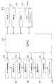
次に、図6を参照しつつ、粘着テープ印刷装置1の制御系について説明する。<Control system of adhesive tape printer>
Next, the control system of the
図6に示すように、粘着テープ印刷装置1には、所定の演算を行う演算部を構成するCPU212が備えられている。 As shown in FIG. 6, the adhesive
CPU212は、RAM213及びROM214に接続され、RAM213の一時記憶機能を利用しつつ、ROM214に予め記憶されたプログラムに従って信号処理を行うことにより、粘着テープ印刷装置1全体の制御を行う。 The
RAM213には、例えばパーソナルコンピュータ等から受信した画像データ形式の印刷データを、被印字基材テープ150の基材層151の表側における所定の印字領域にインク層IKを形成するためのドットパターンデータに展開して記憶する、イメージバッファ213aが備えられている。 In the
ROM214には、所定の制御処理を実行するための制御プログラムが記憶されている。 The
また、CPU212は、3つのモータ駆動回路218,219,220、ヘッド制御回路221、適宜の表示を行う表示部215、及び、ユーザが適宜に操作入力可能な操作部216に接続されている。 Further, the
モータ駆動回路218は、上記搬送ローラ12を駆動する上記搬送用モータM1の駆動制御を行う。また、モータ駆動回路219は、上記巻き取り機構40を駆動する上記巻取用モータM2の駆動制御を行う。また、モータ駆動回路220は、上記搬送ローラ14を駆動する上記搬送用モータM3の駆動制御を行う。 The
ヘッド制御回路221は、上記印刷データに応じて、上記インクジェットヘッド10aに設けられた圧電アクチュエータの駆動制御を行い、ノズルからインクを吐出させる。 The
すなわち、CPU212は、ROM214に記憶された適宜の制御プログラムによって、イメージバッファ213aに記憶された印刷データに従って、被印字基材テープ150の基材層151の表側に対し、ヘッド制御回路221を介しインクジェットヘッド10aにより当該印刷データに対応したインク層IKの形成を行う。 That is, the
<本実施形態による効果>
以上説明したように、本実施形態の粘着テープ印刷装置1には、粘着テープカートリッジTKを装着して使用する。印刷実行時には、被印字基材テープロールR1から繰り出されて搬送ローラ12等により搬送される被印字基材テープ150の表側に対し、インクジェットヘッド10aによりインク層IKの形成が行われる。その後、インク層IKが形成された印字済み基材テープ150′のさらに表側に対し、被覆テープロールR3から繰り出された被覆テープ153が、搬送ローラ14及びサブローラ14aにより貼り合わされ、印字済み粘着テープ150″が生成される。ユーザは、所望の長さの印字済み粘着テープ150″を(被印字基材テープ150に備えられた粘着層152を介し)適宜の被着体に対し貼り付けることにより、例えばラベルや梱包用の封止材として使用する。このとき、上記のようにして構成された結果、印字済み粘着テープ150″は、その表側から裏側に向かって、被覆テープ153、インク層IK、基材層151、及び粘着層152をこの順序で含む積層構造となっている(図2中部分拡大図d参照)。印字済み粘着テープ150″の最も表側に被覆テープ153(被覆層154)が設けられることにより、上記のようにラベルや封止材として使用されるときに表面の擦れによって印字が消えにくくなり、印字の耐久性を保つことができる。<Effects of this embodiment>
As described above, the
また、本実施形態においては、上記印字済み粘着テープ150″が巻き取り機構40により巻き取られ、印字済み粘着テープロールR2として生成される。上述のように印字済み粘着テープ150″が被覆テープ153、インク層IK、基材層151、及び粘着層152をこの順序で含むことから、上記生成された印字済み粘着テープロールR2においては、インク層IKの表側を覆う被覆テープ153と粘着層152とがロール径方向に接する(すなわち、インク層IKと粘着層152との間に被覆テープ153が介在する)状態となる(図5参照)。これにより、インク層IKと粘着層152とが直接接する場合のように、印字済み粘着テープロールR2から印字済み粘着テープ150″が繰り出されて使用されるときにインク層IKが粘着層152側へと引き剥がされ印字に悪影響を与えるのを、防止することができる。 In the present embodiment, the printed
以上のように、本実施形態においては、貼り付けて使用されるときの印字の耐久性を維持するとともに、印字済み粘着テープロールR2からの繰り出し時に印字に悪影響が生じるのを防止できる、最適な特性の印字済み粘着テープ150″を実現することができる。 As described above, in the present embodiment, it is possible to maintain the durability of printing when being used by being attached, and to prevent the printing from being adversely affected when being fed out from the printed adhesive tape roll R2. It is possible to realize the printed
また、本実施形態では特に、上述のように、印字済み粘着テープ150″が被覆テープ153、インク層IK、基材層151、及び粘着層152をこの順序で含み、印字済み粘着テープロールR2においてインク層IKと粘着層152との間に被覆テープ153が介在する。これにより、印字済み粘着テープロールR2から印字済み粘着テープ150″が繰り出されて使用されるときにインク層IKが粘着層152側へと引き剥がされ印字品質に悪影響を与える(インクかすれ等が生じる)のを、防止することができる。 In the present embodiment, in particular, as described above, the printed
また、本実施形態では特に、サブローラ14aにおいて、4つの円筒状接触部142が軸心O4の延設方向に互いに離間して離散配置され、(サブローラ14aが軸心O4の延設方向全長にわたって粘着層152に接するのではなく)それら4つの円筒状接触部142のみが粘着層152に接触する。これにより、上記被印字基材テープ150等の搬送時における粘着層152との接触面積を小さくできるので、搬送抵抗を低減し、より円滑なテープ搬送を行うことができる。 In the present embodiment, in particular, in the sub-roller 14a, the four
また、本実施形態では特に、被覆テープ153が、その裏側に被印字基材テープ150への貼り合わせのための粘着層155を備える。これにより、被覆テープ153の裏側(言い換えれば貼り合わせ側)に設けられた粘着層155により、被覆テープ153と被印字基材テープ150とを確実に貼り合わせて印字済み粘着テープ150″を生成することができる。 In this embodiment, in particular, the covering
なお、本発明は、上記実施形態に限られるものではなく、その趣旨及び技術的思想を逸脱しない範囲内で種々の変形が可能である。以下、そのような変形例を順を追って説明する。 The present invention is not limited to the above-described embodiment, and various modifications can be made without departing from the spirit and technical idea of the present invention. Hereinafter, such modifications will be described in order.
(1)被印字基材テープが被覆テープの貼り合わせ用の粘着層を備える場合
上記実施形態では、被覆テープ153が、被印字基材テープ150への貼り合わせ用の粘着層155を備えていたが、これに限定されるものではなく、被印字基材テープが、被覆テープの貼り合わせ用の粘着層を備えてもよい。(1) When the substrate tape to be printed is provided with an adhesive layer for laminating the covering tape In the above embodiment, the
以下、図7を参照しつつ、本変形例の粘着テープ印刷装置1の構成について説明する。なお、本変形例において、上記実施形態と同様の部分には同符号を付し、適宜説明を省略する。 Hereinafter, the configuration of the
図7に示すように、本変形例では、被印字基材テープロールR1は、前述の被印字基材テープ150に代え、被印字基材テープ150Aを、予め、前述の軸心O1まわりに巻回している。 As shown in FIG. 7, in this modification, the substrate tape roll R1 to be printed is preliminarily wound around the axis O1 in place of the
被印字基材テープ150Aは、前述の基材層151と、前述の粘着層152と、所定の粘着剤により構成された粘着層157(第2貼り合わせ用粘着層に相当)とを備える。そして、被印字基材テープ150Aは、その裏側(図7中部分拡大図a中の左上側)から表側(図7中部分拡大図a中の右下側)へ向かって、粘着層152、基材層151、及び粘着層157をこの順序で含む積層(3層)構造となっている。粘着層157は、被印字基材テープ150Aに対し後述の被覆テープ153Aを貼り合わせるための層である。 The
また、本変形例では、被覆テープロールR3は、前述の被覆テープ153に代え、被覆テープ153Aを、予め、前述の軸心O3まわりに巻回している。 In the present modification, the covering tape roll R3 is wound around the axis O3 in advance, instead of the covering
被覆テープ153Aは、前述の被覆層154により構成されている(図7中部分拡大図b参照)。 The covering
また、本変形例では、前述の搬送ローラ12に代え、搬送ローラ12Aが設けられている。 In this modification, a
搬送ローラ12Aは、被印字基材テープロールR1から繰り出される被印字基材テープ150A(詳細には後述の印字済み基材テープ150A′)に対し、その表側(インク層IK側)から接触する。また、本変形例では、サブローラ12aは、上記印字済み基材テープ150A′に対し、その裏側(粘着層152側)から接触する。これにより、搬送ローラ12A及びサブローラ12aは、それらの間に上記印字済み基材テープ150A′を狭持しつつ、協働して、被印字基材テープ150A及び印字済み基材テープ150A′(以下適宜「被印字基材テープ150A等」という)をテープ幅方向が左右方向となるテープ姿勢で搬送する。 The
また、本変形例では、インクジェットヘッド10aは、搬送ローラ12A、サブローラ12a、搬送ローラ14、及びサブローラ14a(以下適宜「搬送ローラ12A等」という)による被印字基材テープ150A等の搬送に従って、当該被印字基材テープ150Aの表側(粘着層157側)に対し、ノズルからインクを吐出する。これにより、インクジェットヘッド10aは、粘着層157の表側に前述のインク層IKを形成する。なお、粘着層157の表側へのインク層IKの形成が行われた被印字基材テープ150Aを、特に「印字済み基材テープ150A′」という。 Further, in this modification, the
すなわち、印字済み基材テープ150A′は、その裏側(図7中部分拡大図c中の左上側)から表側(図7中部分拡大図c中の右下側)へ向かって、粘着層152、基材層151、粘着層157、及びインク層IKをこの順序で含む積層(4層)構造となっている。 That is, the printed
また、本変形例では、上記印字済み基材テープ150A′、及び、被覆テープロールR3から繰り出される被覆テープ153Aは、当該印字済み基材テープ150A′の表側のインク層IKと、当該被覆テープ153A(被覆層154)の裏側とが対向した状態で、搬送ローラ14とサブローラ14aとの間に狭持されることにより、貼り合わされる。これにより、搬送ローラ14及びサブローラ14aは、それらの間に印字済み基材テープ150A′及び被覆テープ153Aを狭持することにより貼り合わせつつ、協働して、被印字基材テープ150A等及び被覆テープ153Aをテープ幅方向が左右方向となるテープ姿勢で搬送する。 In this modification, the printed
上記のようにして、印字済み基材テープ150A′と被覆テープ153Aとが搬送ローラ14及びサブローラ14aにより貼り合わされる、言い換えれば、表側にインク層IKが形成された印字済み基材テープ150A′の、さらに表側に対し、被覆テープ153Aが貼り合わされることにより、印字済み粘着テープ150A″が生成される。 As described above, the printed
すなわち、印字済み粘着テープ150A″は、その裏側(図7中部分拡大図d中の左上側)から表側(図7中部分拡大図d中の右下側)へ向かって、粘着層152、基材層151、粘着層157、インク層IK、及び被覆層154をこの順序で含む積層(5層)構造となっている。 That is, the printed
なお、本変形例では、特に図示はしないが、上記実施形態においてローラ軸の周囲に複数の円筒状接触部を備える構造となっていた、サブローラ14a、サブローラ12a、及びガイドローラ12bに加え、上記搬送ローラ12Aもまた、これらと同様に、そのローラ軸の周囲に複数の円筒状接触部を備える構造となっている。 In this modification, although not particularly illustrated, in addition to the sub-roller 14a, the sub-roller 12a, and the
そして、本変形例では、巻き取り機構40は、上記のようにして生成された印字済み粘着テープ150A″を、上記実施形態と同様にして、前述の軸心O2まわりにロール状に巻き取ることによって、印字済み粘着テープロールR2を形成する。 In this modification, the winding
以上説明した本変形例においても、上記実施形態と同様、印字済み粘着テープ150A″の最も表側に被覆テープ153A(被覆層154)が設けられることにより、ラベルや封止材として使用されるときに表面の擦れによって印字が消えにくくなり、印字の耐久性を保つことができる。また、上記実施形態と同様、インク層IKと粘着層152とが直接接する場合のように、印字済み粘着テープロールR2から印字済み粘着テープ150A″が繰り出されて使用されるときにインク層IKが粘着層152側へと引き剥がされ印字に悪影響を与えるのを、防止することができる。 Also in this modified example described above, when the
以上のように、本変形例においても、上記実施形態と同様、貼り付けて使用されるときの印字の耐久性を維持するとともに、印字済み粘着テープロールR2からの繰り出し時に印字に悪影響が生じるのを防止できる、最適な特性の印字済み粘着テープ150A″を実現することができる。 As described above, also in this modification, as in the above embodiment, the durability of printing when being used by being attached is maintained, and printing is adversely affected when being fed out from the printed adhesive tape roll R2. It is possible to realize the printed
また、本変形例では、被印字基材テープ150Aが、その表側に、被覆テープ153Aの貼り合わせのための粘着層157を備える。これにより、被印字基材テープ150Aの表側(言い換えれば貼り合わせ側)に設けられた粘着層157により、被覆テープ153Aと被印字基材テープ150Aとを確実に貼り合わせて印字済み粘着テープ150A″を生成することができる。 In this modification, the substrate tape to be printed 150A includes an
(2)その他
以上においては、最も裏側が粘着層152である被印字基材テープ150,150Aを用いた場合を例にとって説明したが、これに限定されるものではない。例えば、粘着層152のさらに裏側に当該粘着層152を覆う剥離紙が設けられた被印字基材テープを用いてもよい。この場合も、上記実施形態等と同様の効果を得ることができる。(2) Others In the above, the case where the printed
また、以上においては、粘着テープ印刷装置1に、インクジェットヘッド10aを設け、当該インクジェットヘッド10aにより、被印字基材テープ150,150Aの表側に対し、インク層IKを形成する場合を例にとって説明したが、これに限定されるものではない。例えば、粘着テープ印刷装置1に、インクリボンを用いて印字形成する印字ヘッドを設け、当該印字ヘッドにより、被印字基材テープの表側に対し、インクリボンからのインクの転写により印字形成してもよい。また例えば、粘着テープ印刷装置1に、感熱材料を用いて印字形成する印字ヘッドを設け、当該印字ヘッドにより、被印字基材テープの表側に対し、感熱材料による発色により印字形成してもよい。これらの場合も、上記実施形態等と同様の効果を得ることができる。 In the above description, the case where the adhesive
なお、図6中に示す矢印は、信号の流れの一例を示すものであり、信号の流れ方向を限定するものではない。 In addition, the arrow shown in FIG. 6 shows an example of the signal flow, and does not limit the signal flow direction.
また、以上既に述べた以外にも、上記実施形態や各変形例による手法を適宜組み合わせて利用しても良い。 In addition to those already described above, the methods according to the above-described embodiments and modifications may be used in appropriate combination.
その他、一々例示はしないが、本発明は、その趣旨を逸脱しない範囲内において、種々の変更が加えられて実施されるものである。 In addition, although not illustrated one by one, the present invention is implemented with various modifications within a range not departing from the gist thereof.
1 粘着テープ印刷装置
3 収納部(第1収納部)
5 収納部(第2収納部)
10a インクジェットヘッド(印字ヘッド)
14 搬送ローラ
14a 搬送ローラ
16 連結アーム
40 巻き取り機構
142 円筒状接触部
150 被印字基材テープ
150A 被印字基材テープ
150′ 印字済み基材テープ
150A′ 印字済み基材テープ
150″ 印字済み粘着テープ
150A″ 印字済み粘着テープ
151 基材層(テープ基材層)
152 粘着層(貼り付け用粘着層)
153 被覆テープ
153A 被覆テープ
155 粘着層(第1貼り合わせ用粘着層)
157 粘着層(第2貼り合わせ用粘着層)
IK インク層
R1 被印字基材テープロール
R2 印字済み粘着テープロール
R3 被覆テープロール
TK 粘着テープカートリッジDESCRIPTION OF
5 Storage part (second storage part)
10a Inkjet head (printing head)
14 Conveying
152 Adhesive layer (adhesive layer for application)
153
157 Adhesive layer (second adhesive layer)
IK ink layer R1 substrate tape roll to be printed R2 printed adhesive tape roll R3 coated tape roll TK adhesive tape cartridge
Claims (2)
Translated fromJapanese前記被印字基材テープの前記厚さ方向の他方側に貼り合わされる被覆テープを、前記第1方向の軸線まわりに巻回した被覆テープロールと、
前記被印字基材テープロールと前記被覆テープロールとを連結するように設けられ、前記厚さ方向及び前記第1方向に直交する第2方向の一方側において前記被印字基材テープロールを回転自在に支持するとともに、前記第2方向の他方側において前記被覆テープロールを回転自在に支持する、連結アームと、
を有し、
前記被印字基材テープロールから繰り出され前記厚さ方向の他方側に印字形成された前記被印字基材テープの、さらに前記厚さ方向の前記他方側に対し、前記被覆テープロールから繰り出された前記被覆テープを貼り合わせ、印字済み粘着テープとして供給可能に構成されている粘着テープカートリッジであって、
前記被印字基材テープは、
前記厚さ方向の前記他方側に、前記被覆テープの前記貼り合わせのための第2貼り合わせ用粘着層を備え、
前記第2貼り合わせ用粘着層に印字形成された前記被印字基材テープの前記厚さ方向の前記他方側に対し前記被覆テープを貼り合わせ、印字済み粘着テープとして供給可能に構成されている
ことを特徴とする粘着テープカートリッジ。A printed substrate tape comprising: a tape substrate layer; and an adhesive layer for attachment provided on one side in the thickness direction of the tape substrate layer, in a first direction orthogonal to the thickness direction. A printed substrate tape roll wound around an axis;
A covering tape roll in which a covering tape to be bonded to the other side in the thickness direction of the substrate tape to be printed is wound around an axis in the first direction;
Provided to connect the substrate tape roll to be printed and the covering tape roll, and the substrate tape roll to be printed is freely rotatable on one side of the thickness direction and the second direction orthogonal to the first direction. And a connecting arm that rotatably supports the covering tape roll on the other side in the second direction,
Have
The printed substrate tape that was fed out from the substrate tape roll to be printed and printed on the other side in the thickness direction was further fed out from the coated tape roll to the other side in the thickness direction. Bonding the covering tape, anadhesive tape cartridge configured to be supplied as a printed adhesive tape,
The printed substrate tape is
On the other side of the thickness direction, a second adhesive layer for bonding of the covering tape is provided,
The coating tape is bonded to the other side in the thickness direction of the substrate tape to be printed printed on the second bonding adhesive layer, and supplied as a printed adhesive tape. An adhesive tape cartridge characterized by the above.
前記被覆テープは、
厚さ方向の一方側に、前記被印字基材テープへの前記貼り合わせのための第1貼り合わせ用粘着層を備える
ことを特徴とする粘着テープカートリッジ。In the adhesive tape cartridge according toclaim 1 ,
The coated tape is
A pressure-sensitive adhesive tape cartridge comprising: a first pressure-sensitive adhesive layer for bonding to the substrate tape to be printed on one side in a thickness direction.
Priority Applications (2)
| Application Number | Priority Date | Filing Date | Title |
|---|---|---|---|
| JP2014080959AJP6269947B2 (en) | 2014-04-10 | 2014-04-10 | Adhesive tape cartridge |
| PCT/JP2015/058600WO2015156105A1 (en) | 2014-04-10 | 2015-03-20 | Adhesive tape printing device and adhesive tape cartridge |
Applications Claiming Priority (1)
| Application Number | Priority Date | Filing Date | Title |
|---|---|---|---|
| JP2014080959AJP6269947B2 (en) | 2014-04-10 | 2014-04-10 | Adhesive tape cartridge |
Publications (2)
| Publication Number | Publication Date |
|---|---|
| JP2015199319A JP2015199319A (en) | 2015-11-12 |
| JP6269947B2true JP6269947B2 (en) | 2018-01-31 |
Family
ID=54551054
Family Applications (1)
| Application Number | Title | Priority Date | Filing Date |
|---|---|---|---|
| JP2014080959AExpired - Fee RelatedJP6269947B2 (en) | 2014-04-10 | 2014-04-10 | Adhesive tape cartridge |
Country Status (1)
| Country | Link |
|---|---|
| JP (1) | JP6269947B2 (en) |
Family Cites Families (6)
| Publication number | Priority date | Publication date | Assignee | Title |
|---|---|---|---|---|
| JPS58166091A (en)* | 1982-03-26 | 1983-10-01 | Teraoka Seiko Co Ltd | Label printer |
| JP2002284131A (en)* | 2001-03-21 | 2002-10-03 | Sato Corp | Label printer without mount |
| JP4459798B2 (en)* | 2004-12-16 | 2010-04-28 | セイコーインスツル株式会社 | Thermally activated device and printer having the same |
| JP2007168434A (en)* | 2006-12-19 | 2007-07-05 | Brother Ind Ltd | cartridge |
| JP6150221B2 (en)* | 2012-05-02 | 2017-06-21 | ブラザー工業株式会社 | Adhesive tape cartridge |
| JP2013233662A (en)* | 2012-05-02 | 2013-11-21 | Brother Industries Ltd | Tape printing apparatus |
- 2014
- 2014-04-10JPJP2014080959Apatent/JP6269947B2/ennot_activeExpired - Fee Related
Also Published As
| Publication number | Publication date |
|---|---|
| JP2015199319A (en) | 2015-11-12 |
Similar Documents
| Publication | Publication Date | Title |
|---|---|---|
| CN108883648B (en) | print box | |
| JP2008265180A (en) | Tape cartridge and tape printer | |
| US9469140B2 (en) | Tape cartridge | |
| JP6213159B2 (en) | Printing device | |
| JP6065260B2 (en) | Printed adhesive tape and printed adhesive tape roll | |
| JP6252773B2 (en) | Adhesive tape cartridge | |
| WO2015064255A1 (en) | Tape cartridge and printing device | |
| JP6269947B2 (en) | Adhesive tape cartridge | |
| WO2015156105A1 (en) | Adhesive tape printing device and adhesive tape cartridge | |
| JP2012245769A (en) | Tape cassette | |
| JP6217971B2 (en) | Tape cartridge and printing apparatus | |
| JP6327516B2 (en) | Adhesive tape printing apparatus and adhesive tape printing method | |
| JP6447760B2 (en) | Adhesive tape cartridge and adhesive tape printer | |
| JP6376358B2 (en) | Masking tape cartridge, printing masking tape roll, and printing apparatus | |
| WO2015046423A1 (en) | Adhesive tape and adhesive tape roll | |
| JP6327503B2 (en) | Tape cartridge | |
| WO2015182235A1 (en) | Adhesive tape printing device, adhesive tape printing method, adhesive tape roll, and ink ribbon | |
| JP6278194B2 (en) | Adhesive tape printing method and adhesive tape roll | |
| JP6256762B2 (en) | Adhesive tape printer | |
| JP6268532B2 (en) | Printing method of adhesive tape, adhesive tape roll, ink ribbon | |
| JP6226136B2 (en) | Adhesive tape printer, adhesive tape roll, and adhesive tape printing method | |
| JP6270155B2 (en) | Medium cartridge and printing apparatus | |
| JP2015193728A (en) | Adhesive tape printer and printing method of adhesive tape | |
| JP6304597B2 (en) | Self-laminating tape holder and self-laminating label | |
| JP2005205632A (en) | Printing tape and tape cartridge provided with the same |
Legal Events
| Date | Code | Title | Description |
|---|---|---|---|
| A621 | Written request for application examination | Free format text:JAPANESE INTERMEDIATE CODE: A621 Effective date:20161209 | |
| A131 | Notification of reasons for refusal | Free format text:JAPANESE INTERMEDIATE CODE: A131 Effective date:20171017 | |
| A521 | Request for written amendment filed | Free format text:JAPANESE INTERMEDIATE CODE: A523 Effective date:20171121 | |
| TRDD | Decision of grant or rejection written | ||
| A01 | Written decision to grant a patent or to grant a registration (utility model) | Free format text:JAPANESE INTERMEDIATE CODE: A01 Effective date:20171206 | |
| A61 | First payment of annual fees (during grant procedure) | Free format text:JAPANESE INTERMEDIATE CODE: A61 Effective date:20171219 | |
| R150 | Certificate of patent or registration of utility model | Ref document number:6269947 Country of ref document:JP Free format text:JAPANESE INTERMEDIATE CODE: R150 | |
| LAPS | Cancellation because of no payment of annual fees |