JP6267612B2 - Medical robot cover - Google Patents
Medical robot coverDownload PDFInfo
- Publication number
- JP6267612B2 JP6267612B2JP2014192992AJP2014192992AJP6267612B2JP 6267612 B2JP6267612 B2JP 6267612B2JP 2014192992 AJP2014192992 AJP 2014192992AJP 2014192992 AJP2014192992 AJP 2014192992AJP 6267612 B2JP6267612 B2JP 6267612B2
- Authority
- JP
- Japan
- Prior art keywords
- medical robot
- arm member
- arm
- cover
- attachment means
- Prior art date
- Legal status (The legal status is an assumption and is not a legal conclusion. Google has not performed a legal analysis and makes no representation as to the accuracy of the status listed.)
- Active
Links
- 230000002093peripheral effectEffects0.000claimsdescription27
- 238000000034methodMethods0.000description13
- 230000033001locomotionEffects0.000description8
- 238000001356surgical procedureMethods0.000description7
- 239000000853adhesiveSubstances0.000description4
- 230000001070adhesive effectEffects0.000description4
- 230000008602contractionEffects0.000description4
- 230000001954sterilising effectEffects0.000description4
- 238000004659sterilization and disinfectionMethods0.000description4
- 238000004804windingMethods0.000description4
- 230000037303wrinklesEffects0.000description3
- 125000004122cyclic groupChemical group0.000description2
- 238000010586diagramMethods0.000description2
- 238000005406washingMethods0.000description2
- 241000894006BacteriaSpecies0.000description1
- 208000004550Postoperative PainDiseases0.000description1
- 206010044565TremorDiseases0.000description1
- 210000001015abdomenAnatomy0.000description1
- 239000002390adhesive tapeSubstances0.000description1
- 238000005452bendingMethods0.000description1
- 238000003745diagnosisMethods0.000description1
- 230000000694effectsEffects0.000description1
- 238000002674endoscopic surgeryMethods0.000description1
- 210000004247handAnatomy0.000description1
- 238000003780insertionMethods0.000description1
- 230000037431insertionEffects0.000description1
- 238000009434installationMethods0.000description1
- 230000009545invasionEffects0.000description1
- 239000003550markerSubstances0.000description1
- 238000012986modificationMethods0.000description1
- 230000004048modificationEffects0.000description1
- 238000002432robotic surgeryMethods0.000description1
- 238000003466weldingMethods0.000description1
- 210000000707wristAnatomy0.000description1
Images


Classifications
- A—HUMAN NECESSITIES
- A61—MEDICAL OR VETERINARY SCIENCE; HYGIENE
- A61B—DIAGNOSIS; SURGERY; IDENTIFICATION
- A61B46/00—Surgical drapes
- A61B46/10—Surgical drapes specially adapted for instruments, e.g. microscopes
- A—HUMAN NECESSITIES
- A61—MEDICAL OR VETERINARY SCIENCE; HYGIENE
- A61B—DIAGNOSIS; SURGERY; IDENTIFICATION
- A61B34/00—Computer-aided surgery; Manipulators or robots specially adapted for use in surgery
- A61B34/30—Surgical robots
- A—HUMAN NECESSITIES
- A61—MEDICAL OR VETERINARY SCIENCE; HYGIENE
- A61B—DIAGNOSIS; SURGERY; IDENTIFICATION
- A61B34/00—Computer-aided surgery; Manipulators or robots specially adapted for use in surgery
- A61B34/30—Surgical robots
- A61B34/35—Surgical robots for telesurgery
- B—PERFORMING OPERATIONS; TRANSPORTING
- B25—HAND TOOLS; PORTABLE POWER-DRIVEN TOOLS; MANIPULATORS
- B25J—MANIPULATORS; CHAMBERS PROVIDED WITH MANIPULATION DEVICES
- B25J19/00—Accessories fitted to manipulators, e.g. for monitoring, for viewing; Safety devices combined with or specially adapted for use in connection with manipulators
- B25J19/0075—Means for protecting the manipulator from its environment or vice versa
Landscapes
- Health & Medical Sciences (AREA)
- Engineering & Computer Science (AREA)
- Surgery (AREA)
- Life Sciences & Earth Sciences (AREA)
- Medical Informatics (AREA)
- Robotics (AREA)
- Biomedical Technology (AREA)
- Heart & Thoracic Surgery (AREA)
- Molecular Biology (AREA)
- Animal Behavior & Ethology (AREA)
- General Health & Medical Sciences (AREA)
- Public Health (AREA)
- Veterinary Medicine (AREA)
- Nuclear Medicine, Radiotherapy & Molecular Imaging (AREA)
- Mechanical Engineering (AREA)
- Manipulator (AREA)
Description
Translated fromJapanese本発明は、外科手術用のロボットに用いられる医療用ロボットカバーに関する。 The present invention relates to a medical robot cover used for a surgical robot.
一般的に外科手術を行う際には、外科手術に用いる医療器具は患者の切開創等からの菌の侵入などを防止するために、不潔とされる医療器具を滅菌された滅菌済みカバーなどを用いて覆い、清潔野としている。即ち、滅菌済みカバーなどで医療器具を覆うことで、無菌状態としている。 In general, when performing a surgical operation, the medical instrument used for the surgical operation is a sterilized cover that is sterilized with a sterilized medical instrument in order to prevent invasion of bacteria from the patient's incision. Used to cover and clean. In other words, the medical device is covered with a sterilized cover or the like to make it sterile.
さらに、近年は、ロボット支援外科手術またはテレロボット外科手術のように、外科医がロボットなどを操作して手術を行う施術方法が行われており、このロボット支援外科手術やテレロボット外科手術などに用いられる医療用ロボットも上述した理由と同様に清潔にする必要がある。 Furthermore, in recent years, surgical methods have been performed in which surgeons operate by operating robots, such as robot-assisted surgery or tele-robot surgery. The medical robot to be used needs to be cleaned for the same reason as described above.
このような滅菌の方法は種々の形態が知られており、例えば、特許文献1に記載された滅菌済みカバーは、外科手術用ロボットシステムの非滅菌部分を覆う滅菌済みカバーであって、外科手術を行うための滅菌野に隣接する外面と、該外科手術用ロボットシステムの該非滅菌部分を受容するキャビティを形成する内面と、該キャビティの開口端における該外面及び該内面の永久的に折り返された折り目と、該ドレープの滅菌側と非滅菌側とを指定する該永久的に折り返された折り目上のマーカーとを含む一体型カフスと、該外面に結合されたファスナーであって、該滅菌済みカバーの容積を減らしつつ該外科手術用ロボットシステムの該非滅菌部分に該滅菌済みカバーを固定するためのファスナーとを備える。 Various forms of such a sterilization method are known. For example, a sterilized cover described in Patent Document 1 is a sterilized cover that covers a non-sterile part of a surgical robot system, and is a surgical operation. An outer surface adjacent to the sterilization field for carrying out, an inner surface forming a cavity for receiving the non-sterile portion of the surgical robotic system, the outer surface at the open end of the cavity and the inner surface permanently folded An integral cuff including a crease and a marker on the permanently folded fold designating a sterilized side and a non-sterile side of the drape; and a fastener coupled to the outer surface, the sterilized cover And a fastener for securing the sterilized cover to the non-sterile part of the surgical robot system while reducing the volume of the surgical robot system.
このような滅菌済みカバーは、システムおよび手術患者を保護するとともに、外科手術時における最大限の動作の自由度および視認性を確保しつつ、簡単に設置され、設置時間を最小限に短縮するように設計されることにより、ロボット外科手術の改善された効率性および有効性を発揮する。 Such a sterilized cover protects the system and the surgical patient and is easy to install and minimizes installation time while ensuring maximum freedom of movement and visibility during surgery. Designed to exhibit improved efficiency and effectiveness of robotic surgery.
しかし、従来の滅菌済みカバーは、ロボットが本体と該本体に対して大きく伸縮又は揺動するアーム部材を備えた医療用ロボットに用いると、アーム部材の伸縮や揺動に伴って、滅菌済みカバーがアーム部材や本体の駆動箇所に挟まることで破損したり、ロボットの動きを制限したり、手技を邪魔することがあった。また、アーム部材の伸縮や揺動動作の際に、自由度が十分にあるとは言えず、これらの動作を阻害するという問題があった。 However, when a conventional sterilized cover is used for a medical robot having a main body and an arm member that is largely expanded and contracted or swinged with respect to the main body, the sterilized cover is attached as the arm member expands and contracts. May be damaged by being caught between the arm member and the drive part of the main body, the movement of the robot may be restricted, or the procedure may be disturbed. In addition, there is a problem that the degree of freedom is not sufficient when the arm member expands and contracts or swings, and this operation is hindered.
また、近年の外科手術では、患者への低侵襲な手術を可能とする内視鏡下手術ロボットを用いた手術が行われている。このような内視鏡下手術ロボットは、傷口が小さいことや術後の疼痛が少ないことなどから、早期の社会復帰が可能となる手術方法であるため、広く普及する手術方法として期待されている。 In recent surgical operations, an operation using an endoscopic surgical robot that enables a minimally invasive operation on a patient is performed. Such an endoscopic surgical robot is expected to be a widely used surgical method because it is a surgical method that enables early rehabilitation because it has a small wound and less postoperative pain. .
このような内視鏡下手術ロボットを用いる場合であっても、上述したロボット支援外科手術やテレロボット外科手術などに用いられる医療用ロボットと同様に滅菌済みカバーを用いて内視鏡下手術ロボットを清潔野とする必要があり、また、微小な動作を確実にアーム部材に伝えるために、アーム部材の動作を阻害することのない滅菌済みカバーが求められている。 Even in the case of using such an endoscopic surgical robot, an endoscopic surgical robot using a sterilized cover is used in the same manner as the medical robot used in the above-described robot-assisted surgery and telerobotic surgery. Therefore, there is a need for a sterilized cover that does not hinder the operation of the arm member in order to reliably transmit a minute operation to the arm member.
本発明は、上記課題を解決するために成されたものであって、本体と該本体に対して伸縮または揺動可能に取り付けられたアーム部材を備える医療用ロボットに用いられる医療用ロボットカバーにおいて、容易に設置することができるとともに、アーム部材の伸縮や揺動によって医療用ロボットカバーが破損することなく、アーム部材の動作を阻害せず、手技を邪魔しない医療用ロボットカバーを提供することを目的とする。 The present invention has been made to solve the above-described problem, and is a medical robot cover used for a medical robot including a main body and an arm member attached to the main body so as to be extendable or swingable. To provide a medical robot cover that can be easily installed, does not damage the medical robot cover due to expansion and contraction and swinging of the arm member, does not hinder the operation of the arm member, and does not disturb the procedure. Objective.
上記課題を解決する本発明に係る医療用ロボットカバーは、基台から立設する本体と、前記本体の一端に揺動又は伸縮自在に取り付けられたアーム部材とを備える医療用ロボットの外表面を覆う医療用ロボットカバーであって、前記本体を覆う胴部を備え、前記医療用ロボットの外表面と対向するカバー内周面に、前記本体又は前記アーム部の少なくとも何れか一方に巻回される取付手段を備え、前記取付手段は、前記胴部の前記本体と対向する内周面に取り付けられた帯状の第1の取付手段を有し、前記第1の取付手段は、両端部に止め合わせ手段が形成され、前記胴部に巻回す際に前記胴部との間に所定の隙間を有するように前記止め合わせ手段によって取り付けられることを特徴とする。A medical robot cover according to the present invention that solves the above-described problems includes an outer surface of a medical robot that includes a main body standing from a base and an arm member that is swingably or telescopically attached to one end of the main body. A medical robot cover for covering,comprising a body portion for covering the main body, and wound around at least one of the main body and the arm portion on an inner peripheral surface of the cover facing the outer surface of the medical robot An attachment means,and the attachment means has a belt-like first attachment means attached to an inner peripheral surface of the body portion facing the main body, and the first attachment means is fastened to both ends. means is formed, and wherein the Rukotomounted by said locking alignment means so as to have a predetermined gap between the body portion when wound around the barrel.
また、本発明に係る医療用ロボットカバーにおいて、前記アーム部材を覆う腕部を備えると好適である。Further, in the medical robot cover according to the present invention, it is preferable to comprisean armportion that covers thefront Symbol arm member.
また、本発明に係る医療用ロボットカバーにおいて、前記取付手段は、前記腕部の外表面に前記アーム部材と共に前記腕部に巻回される第2の取付手段とを含むと好適である。Further, in the medical robot cover according to the present invention, the attachmentmeans, it is preferable that along with the arm member to the outer surface of thefront Kiude portion and a second attachment means to be wound around the arm portion.
さらに、本発明に係る医療用ロボットカバーにおいて、前記胴部には、前記アーム部材の伸縮又は揺動を許容する可動領域を備えると好適である。 Furthermore, in the medical robot cover according to the present invention, it is preferable that the body portion is provided with a movable region that allows the arm member to expand and contract or swing.
さらにまた、本発明に係る医療用ロボットカバーにおいて、前記腕部には、前記腕部を前記アーム部材に接着せしめる接着手段を備えると好適である。 Furthermore, in the medical robot cover according to the present invention, it is preferable that the arm portion is provided with an adhesive means for adhering the arm portion to the arm member.
本発明によれば、医療用ロボットの外表面と対向するカバー内周面に、本体又はアーム部材の少なくとも何れか一方に巻回される取付手段を備えるので、アーム部材が本体に対して伸縮または揺動した場合であってもアーム部材の動作を阻害することなく、医療用ロボットカバーを医療用ロボットに設置することができる。 According to the present invention, the cover inner peripheral surface facing the outer surface of the medical robot is provided with the attaching means wound around at least one of the main body and the arm member. The medical robot cover can be installed on the medical robot without obstructing the operation of the arm member even when it is swung.
また、本発明によれば、本体を覆う胴部と、アーム部材を覆う腕部とを備えるので、確実に医療用ロボットを無菌的に扱うことができると共に、アーム部材の動作に伴って医療用ロボットカバーが損傷することを防止すると共に、この動作を阻害することがない。 In addition, according to the present invention, since the body portion covering the main body and the arm portion covering the arm member are provided, the medical robot can be reliably handled aseptically, and the medical robot can be used along with the operation of the arm member. This prevents the robot cover from being damaged and does not hinder this operation.
また、本発明によれば、前記胴部の前記本体と対向する内周面に取り付けられた第1の取付手段と、前記腕部の外表面に前記アーム部材と共に前記腕部に巻回される第2の取付手段とを含むので、第1の取付手段で本体と胴部の内周面を連結することで、アーム部材の伸縮や揺動といった動作を許容すると共に、第2の取付手段が腕部の外表面に巻回されることで腕部の弛みを防止して医療用ロボットカバーが術野に触れることを防止している。 Further, according to the present invention, the first attachment means attached to the inner peripheral surface of the trunk portion facing the main body, and the arm member are wound around the arm portion together with the arm member on the outer surface of the arm portion. The second attachment means includes the first attachment means to connect the main body and the inner peripheral surface of the body portion, thereby allowing the arm member to expand and swing, and allows the second attachment means to move. It is wound around the outer surface of the arm portion to prevent the arm portion from loosening and the medical robot cover from touching the surgical field.
また、本発明によれば、前記胴部には、前記アーム部材の伸縮又は揺動を許容する可動領域を備えるので、医療用ロボットカバーを医療用ロボットに取り付けてもアーム部材の伸縮又は揺動といった動作を阻害することがない。 Further, according to the present invention, since the body portion is provided with a movable region that allows the arm member to expand and contract, the arm member can expand and contract even if the medical robot cover is attached to the medical robot. The operation is not hindered.
また、本発明によれば、前記腕部には、前記腕部を前記アーム部材に接着せしめる接着手段を備えるので、アーム部材が伸縮又は揺動した場合であっても腕部がアーム部材に対してズレることを防止し、腕部が弛んだり、皺が生じることを防止することができる。 According to the present invention, the arm portion is provided with an adhesive means for bonding the arm portion to the arm member. Therefore, even when the arm member expands or contracts or swings, the arm portion is not attached to the arm member. Misalignment, and it is possible to prevent the arms from loosening and wrinkles.
以下、本発明に係る医療用ロボットカバーについて図面を参照しつつ説明する。なお、以下の実施の形態は、各請求項に係る発明を限定するものではなく、また、実施形態の中で説明されている特徴の組み合わせの全てが発明の解決手段に必須であるとは限らない。 Hereinafter, a medical robot cover according to the present invention will be described with reference to the drawings. The following embodiments do not limit the invention according to each claim, and all combinations of features described in the embodiments are not necessarily essential to the solution means of the invention. Absent.
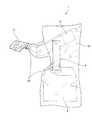
図1は、本発明の実施形態に係る医療用ロボットカバーを医療用ロボットに取り付けた状態を示す図であり、図2は、本発明の実施形態に係る医療用ロボットカバーの構成を説明するため図であり、図3は、本発明の実施形態に係る医療用ロボットカバーを折り畳んだ状態を示す図であり、図4から6は、本発明の実施形態に係る医療用ロボットカバーの取付手順を示す図である。 FIG. 1 is a view showing a state where a medical robot cover according to an embodiment of the present invention is attached to a medical robot, and FIG. 2 is a diagram for explaining a configuration of the medical robot cover according to the embodiment of the present invention. FIG. 3 is a diagram illustrating a state in which the medical robot cover according to the embodiment of the present invention is folded, and FIGS. 4 to 6 illustrate a procedure for attaching the medical robot cover according to the embodiment of the present invention. FIG.
図1に示すように、本実施形態に係る医療用ロボットカバー10は、基台2から立設する本体3と、該本体3の一端に揺動および伸縮自在に取り付けられたアーム部材4を備えた医療用ロボット1に取り付けられて手術中の滅菌を行う。 As shown in FIG. 1, a
医療用ロボット1は、図示しない内視鏡の画像を見ながら医師が手術を行うことができるとともに、医師の手の動きを的確に再現することができるように揺動及び伸縮自在に操作されるアーム部材4が本体3に取り付けられている。また、アーム部材4の先端部5には、鉗子や電気メスなどの手術器具が取り付けられ、医師の手の動きを的確に再現しつつ、人間の手首以上の可動域を有することで正確な手術をより簡便に行うことができるように構成されている。 The medical robot 1 is operated in a swingable and telescopic manner so that a doctor can perform an operation while viewing an image of an endoscope (not shown) and can accurately reproduce the movement of the doctor's hand. An
このように、医療用ロボット1は、開腹することなく、内視鏡や鉗子などが挿通できる程度の小さな傷口で手術を行うことができるので、患者の身体への侵襲度が低い診断・治療を行うことが可能となる。 As described above, the medical robot 1 can perform an operation with a wound that is small enough to allow insertion of an endoscope, forceps, and the like without opening the abdomen, so that diagnosis and treatment with low invasiveness to the patient's body can be performed. Can be done.
なお、先端部5に取り付けた鉗子などの駆動には、ワイヤなどの押し引き動作による制御の他、空気圧を用いて駆動させることができるように構成されている。如何なる駆動方法を採用した場合であっても、鉗子先端の感触を医師にフィードバックすることができるように構成されると、より直感的な手術が可能となり、手術中の医師への負担を減少させることができる。 The forceps attached to the
さらに、手術室内は、滅菌された所謂清潔野であるため、医療用ロボット1を用いる際には、滅菌されていない所謂不潔野との境界を策定するために医療用ロボットカバー10で医療用ロボット1の外表面を覆って手術を行う必要がある。 Furthermore, since the inside of the operating room is a so-called clean field sterilized, when the medical robot 1 is used, the
図1及び2に示すように、本実施形態に係る医療用ロボットカバー10は、本体3及び基台2の外表面を覆う胴部11と、アーム部材4の外表面を覆う腕部12とを備えている。また、本体3及びアーム部材4は、それぞれ第1の取付手段21及び第2の取付手段22からなる取付手段20が巻回されており、該取付手段20によって医療用ロボット1に対して取付固定されている。 As shown in FIGS. 1 and 2, the
図2に示すように、本実施形態に係る医療用ロボットカバー10の胴部11は上辺が閉じられると共に、下辺が開放した袋状に形成されている。さらに、胴部11には袋状に形成された腕部12が短手方向の一方端に取り付けられ、腕部12が取り付けられた他端は互いに閉じ合されておらず開口部14が形成されている。また、開口部14は、面ファスナーや接着テープなどからなる留め部15によって開口の大きさを調整することができるともに、医療用ロボット1に取り付けた後は、留め部15によって開口部14を閉じることができるように構成されている。さらに、腕部12は、胴部11の上辺からオフセットして短手方向の一方端に取り付けられており、胴部11の上方に可動領域17を形成している。 As shown in FIG. 2, the
なお、胴部11の腕部12が取り付けられた側の縁部は、略三角形状に形成されており、この三角形状によって第2の可動領域17aを形成している。この第2の可動領域17aによって胴部11の下端が床に着くことを防止すると共に、アーム部材4が回動などをする際の可動領域を形成している。なお、可動領域17及び第2の可動領域17aは、医療用ロボット1の動き、アーム部材4の伸縮や揺動や本体の回転などに応じて形成すればよく、必要に応じて何れか一方のみ備えても構わない。 In addition, the edge part by which the
本実施形態に係る医療用ロボットカバー10は、胴部11に開口部14及び留め部15を備えているので、医療用ロボット1に取り付ける場合に、確実に清潔野とすると共に開口を大きくとることができるため、取付作業をより容易に行うことが可能となる。 Since the
また、胴部11の下辺は、胴部11の端部を巻き上げた巻上部13が形成されている。この巻上部13は、本実施形態に係る医療用ロボットカバー10が取り付けられる医療用ロボット1の高さに応じて確実に胴部11の長さを調整することで、胴部11の長さが短い場合には、医療用ロボット1の下端まで確実に滅菌を行うことができるように構成されている。また、胴部11の長さが長い場合には、医療用ロボットカバー10の下端が床に触れて不潔になること及び術者が踏むことを防止すること、並びに医療用ロボット1の下に巻き込まれることを防止するために適宜巻上げの長さを調整することも可能である。 Moreover, the lower part of the trunk | drum 11 forms the winding
胴部11の内周面には、第1の取付手段21が取り付けられている。第1の取付手段21は、帯状部材を略半分に折り曲げ、該折り曲げ位置を胴部11の内周面に熱溶着や接着などの手段によって取り付けられている。したがって、第1の取付手段21は、胴部11の内周面に対して両端部が自由端に形成されている。また、第1の取付手段21の両端部には、両端部を閉じるための止め合わせ手段が取り付けられている。止め合わせ手段は、具体的には面ファスナーや両面テープなどが好適に用いられる。 A first attachment means 21 is attached to the inner peripheral surface of the
また、腕部12の外周面には、第2の取付手段22が取り付けられている。第2の取付手段22は、第1の取付手段21と異なり、一端が腕部12の外周面に取り付けられ、他端は自由端に形成され、自由端に形成された端部には、第1の取付手段21と同様に止め合わせ手段が取り付けられている。もしくは、環状に形成したゴムの一部が腕部12の外周面に取り付けられ、アーム部材4の先端を該環状のゴムの中に通すような構成としても良い。このように、本実施形態に係る医療用ロボットカバー10は、第1の取付手段21と第2の取付手段22とによって取付手段を構成している。 A second attachment means 22 is attached to the outer peripheral surface of the
さらに、腕部12の先端(図2における左側)には、内周面に接着手段16が取り付けられている。この接着手段16は、アーム部材4の先端部5に対して腕部12がずれないように腕部12を張り付けることができればどのような構成を採用しても構わないが、例えば両面テープなどを用いると好適である。また、接着手段16は、医療用ロボットカバー10を用いて医療用ロボット1に覆う(カバーリングする)際に起点の目印にもなり、カバーし易い効果もある。そのため、接着手段16は、起点を指し示すような形状、具体的に点となるような丸や四角等、または三角形や矢印等が好適である。なお、接着手段16を、医療用ロボット1に接着させたくない場合や、目印のみの構成だけで良い場合は、接着手段16でなく、腕部12の先端に印を付けるだけでも良い。 Further, an adhesive means 16 is attached to the inner peripheral surface of the tip of the arm portion 12 (left side in FIG. 2). The bonding means 16 may adopt any configuration as long as the
次に、図3から6を参照して本実施形態に係る医療用ロボットカバー10の取付手順について説明を行う。 Next, with reference to FIGS. 3 to 6, a procedure for attaching the
本実施形態に係る医療用ロボットカバー10は、図3に示すように初期状態では折り畳まれている。本実施形態に係る医療用ロボットカバー10は、内周面が不潔野となる医療用ロボット1の外表面と接触し、医療用ロボットカバー10の外周面は、清潔野とする必要があるため、清潔操作を行うために医療用ロボットカバー10の内周面が外側となるように裏返して折り畳まれている。具体的には、内周面が外側となるように裏返して折り畳まれているため、手洗いをすることなく不潔野の作業者が医療用ロボットカバー10の取付作業を行うことができる。 The
第1に図4に示すように、接着手段としての両面テープ16の剥離紙を剥がしてアーム部材4の先端部5に腕部12の先端を接着固定する。その後、アーム部材4を腕部12で覆う。また、開口部14を開いて本体3及び基台2を胴部11で覆うように取り付ける。 First, as shown in FIG. 4, the release paper of the double-
このように、先端部5を腕部12の先端に接着固定しているので、アーム部材4が可動した際に、腕部12に皺などが生じてアーム部材4やアーム部材4の先端部5に取り付けた手術器具の動作に支障が生じることがない。 As described above, since the
次に、図5に示すように、第1の取付手段21の両端を合わせるように本体3に巻きつける。このとき、第1の取付手段21は、端部同士が軽く合わさる程度に貼り付けると好適である。このように取り付けることで、本体3に対して胴部11の自由度が増し、アーム部材4が揺動又は伸縮動作した際に本実施形態に係る医療用ロボットカバー10が当該動作の支障とならないように取り付けることが可能となる。これに対し、外周面から第1の取付手段21を取り付けるように構成すると例えばアーム部材4が揺動する場合は、第1の取付手段21が水平方向に回ることなく当該動作が阻害されることとなる。また、内周面に第1の取付手段21が存在するため、外回りの看護師が取り付け作業を行うことができる。このように第1の取付手段21は、不潔である医療器具と触れる箇所であるため、内周面に取り付けられると好適である。 Next, as shown in FIG. 5, the first attachment means 21 is wound around the
次に、図6に示すように腕部12の外周面に取り付けられた第2の取付手段22をアーム部材4と共に腕部12に巻き回して腕部12をアーム部材4に対して取り付ける。このように、腕部12の外周面を第2の取付手段22によって腕部12が弛みの無いように取り付けることができるので、アーム部材4が伸縮又は揺動動作を行った場合であっても、当該動作の支障とならないように取り付けることが可能となる。また、第2の取付手段22が取り付けられた箇所は、術野に近接してきる箇所であるため、カバーが撓み、手技の妨げとなることを防止することができる。なお、この作業は本実施形態に係る医療用ロボットカバー10の外周面に触れるため、手洗いをした執刀医や器械出し看護師などの清潔野の作業者が行う必要があるが、前述の理由から執刀医や助手が行わなければならない場面があるため、第2の取付手段22は外周面にあることが好適である。 Next, as shown in FIG. 6, the second attachment means 22 attached to the outer peripheral surface of the
なお、開口部14は、医療用ロボット1に本実施形態に係る医療用ロボットカバー10を取り付けた後に、留め部15によって閉塞される。なお留め部15は、図2には3点で留める構成を記載しているが、必要に応じて留め部を増減しても良いし、図2の縦方向に必要な長さを連続して留められるような構成としても良い。また、留め部15は、外回り看護師等の不潔野を触れる従事者によって留められる方が好ましいため、医療用ロボットカバー10の内周面に取り付けられているのが好適である。 The
このように、本実施形態に係る医療用ロボットカバー10は、アーム部材4の先端部5を接着固定すると共に、腕部12の外表面をアーム部材4と共に巻きつける第2の取付手段22を備えているので、腕部12の不要な弛みや皺の発生を抑制することが可能となりアーム部材4の伸縮や揺動といった動作を阻害することがない。 As described above, the
これに対し、胴部11は、本体3と対向する内周面に取り付けられた第1の取付手段21によって本体3に固定されているので、アーム部材4の伸縮及び揺動に伴って腕部12が引っ張られた場合であっても、腕部12の移動に伴って胴部11が適度に移動することでアーム部材4の伸縮及び揺動といった動作を阻害することがない。また、胴部11の上方には、可動領域17が形成されているので、アーム部材4が可動領域17内を自由に可動することができるので、アーム部材4の伸縮や揺動に伴って胴部11が不用意に引っ張られることを防止している。 On the other hand, since the trunk | drum 11 is being fixed to the
以上、本発明の好適な実施形態について説明したが、本発明の技術的範囲は上記実施形態の記載に限定されない。上記実施形態には、多様な変更又は改良を加えることが可能である。 As mentioned above, although preferred embodiment of this invention was described, the technical scope of this invention is not limited to description of the said embodiment. Various modifications or improvements can be added to the embodiment.
例えば、上記実施形態においては、アーム部材4の先端部5に手術器具を取り付けて内視鏡手術に用いられる医療用ロボット1を清潔にする場合について説明を行ったが、清潔野の確保が必要となる対象医療用ロボットは、これに限られず、例えば先端部5に医師の手を載せる手台を設け、手術操作中は静止していて医師の腕を支え、医師が腕の位置を変えるとこれに追従して移動することで、医師の腕の震えや疲労を軽減させて手術操作性を向上させた手台ロボット等に用いても構わない。 For example, in the above embodiment, a case has been described in which a surgical instrument is attached to the
また、第1及び第2の取付手段21,22は、それぞれ胴部11や腕部12に1つずつ取り付けた場合について説明を行ったが、これらの数はこれに限られず、必要に応じて適宜増減することも可能である。 Moreover, although the 1st and 2nd attachment means 21 and 22 demonstrated the case where it each attached to the trunk | drum 11 and the
その様な変更又は改良を加えた形態も本発明の技術的範囲に含まれ得ることが、特許請求の範囲の記載から明らかである。 It is apparent from the description of the scope of claims that embodiments with such changes or improvements can be included in the technical scope of the present invention.
1 医療用ロボット, 2 基台, 3 本体, 4 アーム部材, 5 先端部, 10 医療用ロボットカバー, 11 胴部, 12 腕部, 13 巻上部, 14 開口部, 15 留め部, 16 接着手段, 17 可動領域, 20 取付手段, 21 第1の取付手段, 22 第2の取付手段。
DESCRIPTION OF SYMBOLS 1 Medical robot, 2 base, 3 main body, 4 arm member, 5 front-end | tip part, 10 medical robot cover, 11 trunk | drum, 12 arm part, 13 winding upper part, 14 opening part, 15 fastening part, 16 adhesion | attachment means, 17 movable region, 20 mounting means, 21 first mounting means, 22 second mounting means.
Claims (5)
Translated fromJapanese前記本体の一端に揺動又は伸縮自在に取り付けられたアーム部材とを備える医療用ロボットの外表面を覆う医療用ロボットカバーであって、
前記本体を覆う胴部を備え、
前記医療用ロボットの外表面と対向するカバー内周面に、前記本体又は前記アーム部の少なくとも何れか一方に巻回される取付手段を備え、
前記取付手段は、前記胴部の前記本体と対向する内周面に取り付けられた帯状の第1の取付手段を有し、
前記第1の取付手段は、両端部に止め合わせ手段が形成され、前記胴部に巻回す際に前記胴部との間に所定の隙間を有するように前記止め合わせ手段によって取り付けられることを特徴とする医療用ロボットカバー。A main body erected from the base,
A medical robot cover covering an outer surface of a medical robot comprising an arm member swingably or telescopically attached to one end of the main body,
Comprising a torso that covers the body;
An attachment means wound around at least one of the main body and the arm portion on the inner peripheral surface of the cover facing the outer surface of the medical robot,
The attachment means has a belt-like first attachment means attached to an inner peripheral surface of the body portion facing the body.
Said first attachment means are formed locking fit means at both ends, the Rukotomounted by said locking alignment means so as to have a predetermined gap between the body portion when wound around the body portion Features a medical robot cover.
前記アーム部材を覆う腕部を備えることを特徴とする医療用ロボットカバー。The medical robot cover according to claim 1,
Medical robot cover, characterized in that it comprisesan armportion that covers thefront Symbol arm member.
前記取付手段は、前記腕部の外表面に前記アーム部材と共に前記腕部に巻回される第2の取付手段とを含むことを特徴とする医療用ロボットカバー。The medical robot cover according to claim 2,
It said mountingmeans, medical robot cover; and a second attachment means to be wound around the arm portion together with the arm member to the outer surface of thefront Kiude portion.
前記胴部には、前記アーム部材の伸縮又は揺動を許容する可動領域を備えることを特徴とする医療用ロボットカバー。The medical robot cover according to claim 2 or 3,
The medical robot cover according to claim 1, wherein the body includes a movable region that allows the arm member to expand and contract or swing.
前記腕部には、前記腕部を前記アーム部材に接着せしめる接着手段を備えることを特徴とする医療用ロボットカバー。In the medical robot cover according to any one of claims 2 to 4,
The medical robot cover according to claim 1, wherein the arm portion is provided with an adhesion unit that adheres the arm portion to the arm member.
Priority Applications (5)
| Application Number | Priority Date | Filing Date | Title |
|---|---|---|---|
| JP2014192992AJP6267612B2 (en) | 2014-09-22 | 2014-09-22 | Medical robot cover |
| PCT/JP2015/004568WO2016047066A1 (en) | 2014-09-22 | 2015-09-08 | Medical robot cover |
| US15/509,712US20170290632A1 (en) | 2014-09-22 | 2015-09-08 | Medical robot cover |
| DE112015004290.3TDE112015004290T5 (en) | 2014-09-22 | 2015-09-08 | Cover for a medical robot |
| CN201580051000.7ACN107148251B (en) | 2014-09-22 | 2015-09-08 | Medical robot cover |
Applications Claiming Priority (1)
| Application Number | Priority Date | Filing Date | Title |
|---|---|---|---|
| JP2014192992AJP6267612B2 (en) | 2014-09-22 | 2014-09-22 | Medical robot cover |
Publications (2)
| Publication Number | Publication Date |
|---|---|
| JP2016064449A JP2016064449A (en) | 2016-04-28 |
| JP6267612B2true JP6267612B2 (en) | 2018-01-24 |
Family
ID=55580617
Family Applications (1)
| Application Number | Title | Priority Date | Filing Date |
|---|---|---|---|
| JP2014192992AActiveJP6267612B2 (en) | 2014-09-22 | 2014-09-22 | Medical robot cover |
Country Status (5)
| Country | Link |
|---|---|
| US (1) | US20170290632A1 (en) |
| JP (1) | JP6267612B2 (en) |
| CN (1) | CN107148251B (en) |
| DE (1) | DE112015004290T5 (en) |
| WO (1) | WO2016047066A1 (en) |
Families Citing this family (14)
| Publication number | Priority date | Publication date | Assignee | Title |
|---|---|---|---|---|
| CA2902058A1 (en) | 2013-03-15 | 2014-09-18 | Stryker Corporation | Assembly for positioning a sterile surgical drape relative to optical position sensors |
| JP6538498B2 (en)* | 2015-09-15 | 2019-07-03 | ファナック株式会社 | Robot with a wrist having a hollow movable element and a waterproof structure |
| CN115252149A (en) | 2016-07-14 | 2022-11-01 | 直观外科手术操作公司 | Surgical drape installation aids |
| CA3017680A1 (en) | 2017-09-19 | 2019-03-19 | Memic Innovative Surgery Ltd. | Surgical drape |
| US11096754B2 (en) | 2017-10-04 | 2021-08-24 | Mako Surgical Corp. | Sterile drape assembly for surgical robot |
| JP6936713B2 (en)* | 2017-11-27 | 2021-09-22 | 株式会社デンソーウェーブ | Protective jacket for robots |
| GB2599311B8 (en)* | 2018-03-26 | 2023-05-24 | Cmr Surgical Ltd | Surgical drape |
| CN113453643B (en) | 2018-12-30 | 2025-05-27 | 莫门提斯外科有限公司 | Surgical drapes for robotic devices |
| IT201900001321A1 (en)* | 2019-01-30 | 2020-07-30 | Ima Spa | METHOD FOR THE REALIZATION OF AN ARTICULATED AUTOMATIC OPERATING DEVICE AND RELATIVE ARTICULATED AUTOMATIC OPERATING DEVICE. |
| JP2021171345A (en)* | 2020-04-27 | 2021-11-01 | 株式会社メディカロイド | Sterile drape and surgery support robot |
| JP7381159B2 (en)* | 2021-12-08 | 2023-11-15 | リバーフィールド株式会社 | drape |
| CN114767278A (en)* | 2022-04-20 | 2022-07-22 | 绍兴梅奥心磁医疗科技有限公司 | Robot sterile bag and sterile operation device |
| WO2024147203A1 (en)* | 2023-01-06 | 2024-07-11 | リバーフィールド株式会社 | Tip drape and drape set |
| DE102023110099A1 (en) | 2023-04-20 | 2024-10-24 | avateramedical GmBH | Sterile cover of a robot unit for robot-assisted surgery |
Family Cites Families (23)
| Publication number | Priority date | Publication date | Assignee | Title |
|---|---|---|---|---|
| US3424153A (en)* | 1966-12-23 | 1969-01-28 | Kimberly Clark Co | Disposable surgical legging |
| US3721999A (en)* | 1972-01-24 | 1973-03-27 | Cenco Medical Health Supply Co | Surgical gown and method of folding |
| US3803640A (en)* | 1973-04-19 | 1974-04-16 | Bard Inc C R | Surgeon{40 s gown with cummerbund |
| US4535481A (en)* | 1984-07-12 | 1985-08-20 | Kimberly-Clark Corporation | Surgical gown for high fluid procedures |
| US4799779A (en)* | 1988-03-22 | 1989-01-24 | Mesmer Jeffrey C | Microscope drape |
| JP2988981B2 (en)* | 1990-08-08 | 1999-12-13 | オリンパス光学工業株式会社 | Surgical microscope drape |
| US5970980A (en)* | 1996-07-12 | 1999-10-26 | Adair; Edwin L. | Sterile encapsulated operating room video monitor and video monitor support device |
| US7727244B2 (en)* | 1997-11-21 | 2010-06-01 | Intuitive Surgical Operation, Inc. | Sterile surgical drape |
| JP2000312685A (en)* | 1999-04-30 | 2000-11-14 | Olympus Optical Co Ltd | Microscope system for operation |
| US6543307B2 (en)* | 2001-04-06 | 2003-04-08 | Metrica, Inc. | Robotic system |
| US20050094269A1 (en)* | 2003-10-31 | 2005-05-05 | Moses Gary L. | Microscope drape coupling system and method |
| GB2411119A (en)* | 2004-02-18 | 2005-08-24 | Southern Derbyshire Acute Hosp | A Medical Sleeve |
| US7533673B2 (en)* | 2004-12-23 | 2009-05-19 | Kimberly-Clark Worldwide, Inc. | Surgical drape with patient retraining/positioning device |
| DE102008005901B4 (en)* | 2008-01-24 | 2018-08-09 | Deutsches Zentrum für Luft- und Raumfahrt e.V. | Sterile barrier for a surgical robot with torque sensors |
| US7886743B2 (en)* | 2008-03-31 | 2011-02-15 | Intuitive Surgical Operations, Inc. | Sterile drape interface for robotic surgical instrument |
| DE102009019695B4 (en)* | 2009-05-05 | 2011-06-16 | Deutsches Zentrum für Luft- und Raumfahrt e.V. | Sterile covering system for the sterile disguising of a medical robotic arm and method for the sterile disguising of a medical robotic arm |
| EP2445439A4 (en)* | 2009-06-22 | 2015-09-23 | Contour Fabricators Inc | Surgical drape and method providing a sterile surface therewith |
| KR101590163B1 (en)* | 2009-10-01 | 2016-01-29 | (주)미래컴퍼니 | Surgical robot and sterile drape covering the same |
| US20130167847A1 (en)* | 2011-08-24 | 2013-07-04 | Kurk Anthony Rogers | Universal sterile drape and support system for in-operating-room safe patient handling equipment |
| DE102012207060A1 (en)* | 2012-04-27 | 2013-10-31 | Deutsches Zentrum für Luft- und Raumfahrt e.V. | Robot assembly for use in medical fields |
| DE102013002813B4 (en)* | 2013-02-19 | 2017-11-09 | Rg Mechatronics Gmbh | Holding device with at least one jaw for a robotic surgical system |
| US10285767B2 (en)* | 2013-03-14 | 2019-05-14 | Source Surgical, Inc. | Medical drape and methods of covering equipment with medical drapes |
| US10064440B2 (en)* | 2013-11-20 | 2018-09-04 | Ian Levine | Medical gown |
- 2014
- 2014-09-22JPJP2014192992Apatent/JP6267612B2/enactiveActive
- 2015
- 2015-09-08CNCN201580051000.7Apatent/CN107148251B/ennot_activeExpired - Fee Related
- 2015-09-08DEDE112015004290.3Tpatent/DE112015004290T5/ennot_activeWithdrawn
- 2015-09-08USUS15/509,712patent/US20170290632A1/ennot_activeAbandoned
- 2015-09-08WOPCT/JP2015/004568patent/WO2016047066A1/enactiveApplication Filing
Also Published As
| Publication number | Publication date |
|---|---|
| CN107148251B (en) | 2020-05-01 |
| CN107148251A (en) | 2017-09-08 |
| JP2016064449A (en) | 2016-04-28 |
| DE112015004290T5 (en) | 2017-06-14 |
| US20170290632A1 (en) | 2017-10-12 |
| WO2016047066A1 (en) | 2016-03-31 |
Similar Documents
| Publication | Publication Date | Title |
|---|---|---|
| JP6267612B2 (en) | Medical robot cover | |
| JP5193049B2 (en) | Surgical drape | |
| AU2019213554B2 (en) | Surgical drape | |
| JP2021166818A (en) | Rotation auxiliary port | |
| US20110238084A1 (en) | Surgical instrument | |
| US11389258B2 (en) | Surgical drape including unrolling mechanism | |
| US20190298469A1 (en) | Mechanism for managing and retaining a surgical drape | |
| CN112618023B (en) | Sterile isolation device and surgical robot system | |
| CN105342704B (en) | A kind of minimally invasive reduction of the fracture machine people | |
| JP7641648B2 (en) | MASTER WORKSTATION FOR ROBOTIC SURGERY, STERILE SURGICAL FIELD, SURGICAL ROBOT SYSTEM AND METHOD | |
| US20190269478A1 (en) | Fixing stand | |
| JP2018068517A (en) | Endoscope fixing means | |
| KR20100078562A (en) | Surgical instrument, master interface of surgical robot for manipulating the same and operation method of surgical robot | |
| JP7577401B1 (en) | Drape set | |
| JP7657510B2 (en) | Front drape and drape set | |
| WO2024147205A1 (en) | Drape set and draping method | |
| KR20120039281A (en) | Surgical instrument and surgical robotic system incluindg the same | |
| GB2598877A (en) | Surgical drape | |
| GB2602387A (en) | Surgical drape | |
| GB2597885A (en) | Surgical drape |
Legal Events
| Date | Code | Title | Description |
|---|---|---|---|
| A621 | Written request for application examination | Free format text:JAPANESE INTERMEDIATE CODE: A621 Effective date:20170316 | |
| A131 | Notification of reasons for refusal | Free format text:JAPANESE INTERMEDIATE CODE: A131 Effective date:20170926 | |
| A521 | Request for written amendment filed | Free format text:JAPANESE INTERMEDIATE CODE: A523 Effective date:20171120 | |
| TRDD | Decision of grant or rejection written | ||
| A01 | Written decision to grant a patent or to grant a registration (utility model) | Free format text:JAPANESE INTERMEDIATE CODE: A01 Effective date:20171212 | |
| R150 | Certificate of patent or registration of utility model | Ref document number:6267612 Country of ref document:JP Free format text:JAPANESE INTERMEDIATE CODE: R150 | |
| S111 | Request for change of ownership or part of ownership | Free format text:JAPANESE INTERMEDIATE CODE: R313117 | |
| R350 | Written notification of registration of transfer | Free format text:JAPANESE INTERMEDIATE CODE: R350 | |
| R250 | Receipt of annual fees | Free format text:JAPANESE INTERMEDIATE CODE: R250 | |
| R250 | Receipt of annual fees | Free format text:JAPANESE INTERMEDIATE CODE: R250 | |
| R250 | Receipt of annual fees | Free format text:JAPANESE INTERMEDIATE CODE: R250 | |
| R250 | Receipt of annual fees | Free format text:JAPANESE INTERMEDIATE CODE: R250 | |
| R250 | Receipt of annual fees | Free format text:JAPANESE INTERMEDIATE CODE: R250 |