JP6267415B2 - Drug diffusion device - Google Patents
Drug diffusion deviceDownload PDFInfo
- Publication number
- JP6267415B2 JP6267415B2JP2012124703AJP2012124703AJP6267415B2JP 6267415 B2JP6267415 B2JP 6267415B2JP 2012124703 AJP2012124703 AJP 2012124703AJP 2012124703 AJP2012124703 AJP 2012124703AJP 6267415 B2JP6267415 B2JP 6267415B2
- Authority
- JP
- Japan
- Prior art keywords
- lock lever
- injection button
- lever
- medicine
- insertion hole
- Prior art date
- Legal status (The legal status is an assumption and is not a legal conclusion. Google has not performed a legal analysis and makes no representation as to the accuracy of the status listed.)
- Active
Links
Images


Classifications
- A—HUMAN NECESSITIES
- A01—AGRICULTURE; FORESTRY; ANIMAL HUSBANDRY; HUNTING; TRAPPING; FISHING
- A01M—CATCHING, TRAPPING OR SCARING OF ANIMALS; APPARATUS FOR THE DESTRUCTION OF NOXIOUS ANIMALS OR NOXIOUS PLANTS
- A01M1/00—Stationary means for catching or killing insects
- A01M1/20—Poisoning, narcotising, or burning insects
- A01M1/2022—Poisoning or narcotising insects by vaporising an insecticide
- A01M1/2027—Poisoning or narcotising insects by vaporising an insecticide without heating
- A01M1/2038—Holders or dispensers for pressurized insecticide, e.g. pressurized vessels, cans
Landscapes
- Life Sciences & Earth Sciences (AREA)
- Pest Control & Pesticides (AREA)
- Health & Medical Sciences (AREA)
- General Health & Medical Sciences (AREA)
- Toxicology (AREA)
- Engineering & Computer Science (AREA)
- Insects & Arthropods (AREA)
- Wood Science & Technology (AREA)
- Zoology (AREA)
- Environmental Sciences (AREA)
- Catching Or Destruction (AREA)
- Containers And Packaging Bodies Having A Special Means To Remove Contents (AREA)
Description
Translated fromJapanese本発明は、例えば害虫駆除剤等の薬剤を放散する薬剤放散装置に関するものである。 The present invention relates to a drug diffusion device for releasing a drug such as a pest control agent.
従来から、この種の薬剤放散装置として、例えば、特許文献1に開示されているように、薬剤と共に圧縮ガスが収容された耐圧容器と、耐圧容器に設けられた定量噴射バルブのステムを操作する噴射用ボタンとを備えた装置が知られている。このものでは、使用者が噴射用ボタンを押すことでステムが押されて定量噴射バルブが開放され、耐圧容器内の薬剤が圧縮ガスによって空気中に噴霧される。 Conventionally, as this type of drug diffusing device, for example, as disclosed in
また、特許文献1の薬剤放散装置には、噴射用ボタンが誤って押されてしまうのを防止するための誤作動防止レバーが設けられている。誤作動防止レバーは、装置本体に対して揺動自在に取り付けられている。誤作動防止レバーが一方向に揺動した状態では、誤作動防止レバーのストッパ部が噴射用ボタンと装置本体との間に入り込んで噴射用ボタンを押すことができなくなり、一方、誤作動防止レバーが他方向に揺動した状態では、ストッパ部が噴射用ボタンと装置本体との間から抜け出て噴射用ボタンを押すことができるようになる。 Further, the medicine diffusion device of
上記特許文献1の装置では、噴射用ボタンを操作可能にする操作可能状態と操作不能にする操作不能状態とに切り替えるにあたり、誤作動防止用レバーを揺動させるようにしている。 In the device of
ところが、誤作動防止用レバーのストッパ部が噴射用ボタンによって覆われていて外部から視認できないので、誤作動防止用レバーがどちらの状態にあるは、通常の使用状態で使用者が把握することができない。従って、誤作動防止用レバーが実際には操作可能状態にあるのに、使用者が操作不能状態であると思い込んでしまうことがあり、誤作動防止レバーの機能を必ずしも十分に発揮できないことが考えられる。 However, since the stopper part of the malfunction prevention lever is covered with the injection button and cannot be seen from the outside, the malfunction prevention lever can be grasped by the user under normal use conditions. Can not. Therefore, even though the malfunction prevention lever is actually in an operable state, the user may assume that the malfunction prevention lever is in an inoperable state, and the malfunction prevention lever function cannot always be fully realized. It is done.
本発明は、かかる点に鑑みてなされたものであり、その目的とするところは、使用者が薬剤を誤って噴射してしまうのを防止することにある。 This invention is made | formed in view of this point, The place made into the objective is to prevent that a user accidentally injects a chemical | medical agent.
本発明では、上記目的を達成するために、噴射用ボタンが操作されていないときに該ボタンが操作不能状態となるように誤作動防止機構を動作させるようにした。 In the present invention, in order to achieve the above object, the malfunction prevention mechanism is operated so that the button becomes inoperable when the injection button is not operated.
第1の発明は、
薬剤を収容する容器と、
上記容器内の薬剤を一定量だけ噴射させるための噴射用ボタンと、
上記噴射用ボタンを操作可能状態と操作不能状態とに切り替える誤作動防止機構とを備え、該誤作動防止機構は、上記噴射用ボタンが操作されていないときに該噴射用ボタンが操作不能状態となるように動作する薬剤放散装置において、
上記誤作動防止機構は、ロックレバーと、該ロックレバーを付勢する付勢部材とを備え、該付勢部材は、装置本体の内部に収容され、
上記装置本体には、上記ロックレバーを揺動自在に支持するレバー用支軸が上方へ突出するように設けられ、
上記ロックレバーの長手方向中間部には、上記レバー用支軸が挿通する挿通孔が形成され、
上記ロックレバーの上記挿通孔よりも先端側は、操作方向に押された上記噴射用ボタンに当接することで該噴射用ボタンの操作方向への動きを阻止する部分とされ、該噴射用ボタンの動きを阻止する部分は、上記ロックレバーの上記レバー用支軸周りの揺動により、上記噴射用ボタンの操作方向への動きを阻止して操作不能状態にする位置と、上記噴射用ボタンの操作方向への動きを許容して操作可能状態にする位置とに切り替えられ、
上記ロックレバーの上記挿通孔よりも基端側には、使用者が該ロックレバーを揺動操作する板状の操作部が上記レバー用支軸周りの揺動方向に延びるように設けられ、該操作部から上記挿通孔が形成された部分まで上方へ向けて延びるとともに下側へ行くほど断面積が拡大するように形成された中間板部が設けられ、
上記付勢部材は、上記ロックレバーにおける上記挿通孔と上記操作部との間の上記中間板部の下側の側面に接触し、上記噴射用ボタンの操作方向への動きを阻止する方向に該ロックレバーが揺動するように該ロックレバーに対して付勢力を作用させていることを特徴とするものである。The first invention is
A container for containing a medicine;
An injection button for injecting a certain amount of medicine in the container;
A malfunction prevention mechanism for switching the injection button between an operable state and an inoperable state, and the malfunction prevention mechanism is configured so that the injection button is in an inoperable state when the injection button is not operated. In a drug diffusion device that operates as follows:
The malfunction prevention mechanism includes a lock lever and a biasing member that biases the lock lever, and the biasing member is housed inside the apparatus main body.
The apparatus body is provided with a lever support shaft that pivotably supports the lock lever so as to protrude upward,
An insertion hole through which the lever support shaft is inserted is formed in the middle portion in the longitudinal direction of the lock lever,
The distal end side of the lock lever from the insertion hole is a part that prevents the injection button from moving in the operation direction by contacting the injection button pushed in the operation direction. The part that prevents the movement includes a position where the movement of the injection button is prevented by moving the lock lever around the lever support shaft and the operation of the injection button is disabled. Can be switched to a position to allow operation in the direction and enable operation,
The base end side than the insertion hole of the lock lever, the userplate-shaped operation unit operated to swing the lock lever is providedso as to extend in the swing direction around the supporting shaft for thelever,the An intermediate plate portion is provided that extends upward from the operation portion to the portion where the insertion hole is formed and is formed so that the cross-sectional area increases toward the lower side,
The biasing member is in contact witha lower side surface of the intermediate plate portion betweenthe insertion hole and the operation portion in the lock lever, and prevents the movement of the injection button in the operation direction. A biasing force is applied to the lock lever so that the lock lever swings.
この構成によれば、使用者が噴射用ボタンを操作していないときに、噴射用ボタンが操作不能状態となるように誤作動防止機構を動作させることが可能になる。これにより、噴射用ボタンが誤って押されてしまうのを防止するという、誤作動防止機構の機能を十分に発揮させることが可能になる。 According to this configuration, when the user is not operating the injection button, the malfunction prevention mechanism can be operated so that the injection button becomes inoperable. Accordingly, it is possible to sufficiently exhibit the function of the malfunction prevention mechanism that prevents the injection button from being accidentally pressed.
また、誤作動防止機構のロック部材が付勢部材によって操作不能位置に付勢されるので、使用者が噴射用ボタンを操作していないときにロック部材を操作不能位置に確実に位置付けることが可能になる。 In addition, since the lock member of the malfunction prevention mechanism is urged to the inoperable position by the urging member, the lock member can be reliably positioned at the inoperable position when the user is not operating the injection button. become.
また、付勢部材を装置本体の内部に収容してコンパクトにまとめながら、付勢部材による付勢力をロック部材に確実に作用させることが可能になる。 Further, it is possible to reliably apply the urging force by the urging member to the lock member while accommodating the urging member inside the apparatus main body and collecting them in a compact manner.
第1の発明によれば、噴射用ボタンが操作されていないときに噴射用ボタンが操作不能状態となるように誤作動防止機構を動作させることができるので、誤作動防止機構の機能を十分に発揮させることができる。 According to the first invention, since the malfunction prevention mechanism can be operated so that the ejection button becomes inoperable when the ejection button is not operated, the function of the malfunction prevention mechanism is sufficient. It can be demonstrated.
また、誤作動防止機構のロック部材を、噴射用ボタンの操作不能位置に付勢するようにしたので、噴射用ボタンが誤って押されてしまうのを確実に防止できる。 In addition, since the lock member of the malfunction prevention mechanism is urged to the position where the injection button cannot be operated, it is possible to reliably prevent the injection button from being accidentally pressed.
また、付勢部材を装置本体の内部に収容したので、薬剤放散装置をコンパクトにまとめて見栄えを良好にしながら、ロック部材を付勢部材の付勢力によって確実に操作不能位置に位置付けることができる。 In addition, since the urging member is housed inside the apparatus main body, the lock member can be reliably positioned at the inoperable position by the urging force of the urging member, while the medicine-dispersing device is compactly packed and has a good appearance.
以下、本発明の実施形態を図面に基づいて詳細に説明する。尚、以下の好ましい実施形態の説明は、本質的に例示に過ぎず、本発明、その適用物或いはその用途を制限することを意図するものではない。 Hereinafter, embodiments of the present invention will be described in detail with reference to the drawings. It should be noted that the following description of the preferred embodiment is merely illustrative in nature, and is not intended to limit the present invention, its application, or its use.
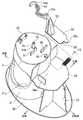
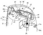
図1は、本発明の実施形態にかかる薬剤放散装置1を示すものである。薬剤放散装置1は、図2にも示すように、装置本体2と、薬剤を収容する薬剤容器3とを備えている。装置本体2は、内部構造体10と、内部構造体10を覆うカバー11とを備えている。図3にも示すように、内部構造体10には、薬剤容器3内の薬剤を噴射させるための噴射用ボタン12と、噴射用ボタン12を操作可能状態と操作不能状態とに切り替えるための誤作動防止機構13とが設けられている。 FIG. 1 shows a
尚、この実施形態の説明では、説明の便宜を図るために、使用状態において使用者側となる側を手前側といい、また、使用者と反対側になる側を奥側といい、使用者から見て右側を右側といい、使用者から見て左側を左側というものとする。 In the description of this embodiment, for convenience of explanation, the side that is the user side in the usage state is referred to as the near side, and the side that is opposite to the user is referred to as the back side. The right side as viewed from the right side is referred to as the right side, and the left side as viewed from the user is referred to as the left side.
図2に示すように、薬剤容器3は、円筒状の耐圧容器からなるものである。薬剤容器3は透光性を有する部材で構成されており、従って、内部の薬剤の残量を外部から視認することができる。 As shown in FIG. 2, the
薬剤容器3の上部には、定量噴射バルブ3aが設けられている。定量噴射バルブ3aは、薬剤容器3の上部中央から上方へ突出するバルブステム3bを有している。図4及び図5に示すように、バルブステム3bの上端には、薬剤の吐出口3cが開口している。バルブステム3bは定量噴射バルブ3aの弁体(図示せず)を操作するためのものであり、図示しないが、下方からスプリングにて上方に常時付勢されている。バルブステム3bが押し上げられた状態で定量噴射バルブ3aが閉状態となる一方、バルブステム3bをスプリングの付勢力に抗して押し下げることで定量噴射バルブ3aが開状態となる。この定量噴射バルブ3aは、1回の開放動作によって薬剤容器3内の薬剤を一定量(例えば0.1ml〜0.2ml程度)だけ放出するように構成された周知の構造のものである。 A
薬剤容器3に収容する薬剤としては、例えばピレスロイド系殺虫剤、カーバメート系殺虫剤、有機リン系殺虫剤等が挙げられるが、ピレスロイド系殺虫剤が好適である。そして、ピレスロイド系殺虫剤の中でも、良好な害虫駆除効果といったことで、トランスフルトリン(商品名:バイオスリン)、メトフルトリン(商品名:エミネンス)、エンペントリン(商品名:ペーパースリン)、テラレスリン、プロフルトリン等がよい。なお、薬剤は、これに限定されるものではなく、同様の害虫駆除効果を有するものなら他のものでもよい。また、薬剤は、薬剤のみ、薬剤を脂肪族炭化水素またはアルコールからなる有機溶剤に溶解して、これを原液として用いてもよい。 Examples of the medicine accommodated in the
また、この薬剤容器3には、上記薬剤と共に噴射剤も収容しており、この噴射剤としては、液化石油ガス(LPG)、ジメチルエーテル(DME)、ハロゲン化炭化水素、圧縮窒素、圧縮炭酸ガスからなる群より選ばれた少なくとも1つである。なお、噴射剤は、これに限定されるものではなく、同様の機能を有するものなら他のものでもよい。さらに、この薬剤容器3には、薬剤や噴射剤と共に溶液等も収容するようにしてもよい。 The
薬剤の吐出口3cの口径は、薬剤容器3から放出された薬剤を非常に細かな霧状の粒子とするために小さくするのが好ましく、その範囲としては、直径1.5mmの円に相当する開口面積以下が好ましく、さらに好ましくは直径0.3mm〜0.7mmの円に相当する開口面積である。 The diameter of the
吐出口3cの口径を小さくすることにより、薬剤が放出する際に薬剤が細孔を速い速度で通過することになる。これにより、放出された薬剤の粒子径が60μm以下、最も良好な値として5〜15μmといった極めて小さなものにすることができ、これにより、薬剤が室内等の空間を長時間にわたって漂うようになり、また、薬剤が床や壁等に付着しても室温程度の熱エネルギーで、再び薬剤が蒸散し、空間を漂うようになる。これらのことで、薬剤における害虫駆除効果を長時間にわたって持続させることができる。そして、このとき、1回の薬剤の放出すなわち噴霧によって、四畳半〜八畳程度の部屋の場合、薬剤における害虫駆除効果は約12時間持続する。 By reducing the diameter of the
内部構造体10は、手前側から奥側へ延びる略楕円形の底板部30と、底板部30から上方へ延びる略円筒状の薬剤容器収容部31と、底板部30から上方へ延びる縦板部33とを備えている。薬剤容器収容部31は底板部30の奥側寄りに位置し、縦板部33は底板部30の手前側寄りに位置している。図2に示すように、底板部30の奥側には薬剤を薬剤容器収容部31に収容するための収容孔30cが形成されている。この収容孔30cは、着脱式のキャップCにより閉塞されるようになっている。 The
薬剤容器収容部31は、薬剤容器3の外周面及び上部を囲むように形成されている。図3等に示すように、薬剤容器収容部31の周壁部には、貫通孔31aが形成されている。薬剤容器収容部31の上壁部の略中央部には、薬剤容器3のバルブステム3bが挿通するステム挿通孔31bが形成されている。バルブステム3bはステム挿通孔31bから上方へ突出している。 The medicine
薬剤容器収容部31の上壁部の奥側の縁部近傍には、噴射用ボタン12を揺動可能に支持するボタン用支軸35が設けられている。ボタン用支軸35は、薬剤容器収容部31の上壁部の左右方向中央部において左右方向に延びている。薬剤容器収容部31の上壁部におけるステム挿通孔31bよりも手前側には、第1ストッパ37と第2ストッパ38とが形成されている。第1ストッパ37は、第2ストッパ38よりも奥側に位置している。第1ストッパ37は、上方へ突出して左右方向に延びる板状に形成されており、薬剤容器収容部31の上壁部の左側に偏位している。第2ストッパ38は、第1ストッパ37と略平行に延びる板状に形成されており、薬剤容器収容部31の上壁部の右側に変位している。 A
さらに、薬剤容器収容部31の上壁部における第2ストッパ38よりも手前側には、誤作動防止機構13を構成するロックレバー(ロック部材)50を揺動自在に支持するレバー用支軸39が上方へ突出するように形成されている。 Further, on the front side of the upper wall portion of the medicine
内部構造体10の縦板部33は、薬剤容器収容部31の周壁部と一体化している。縦板部33の上部には、略水平に延びる上板部34が形成されている。上板部34の上面における左寄りの部位には、後述するスプリング51を支持するスプリング支持板34aが上方へ突出して奥行方向に延びるように設けられている。 The
図3に示すように、噴射用ボタン12は、手前側から奥側へ延びる押圧板部40と、押圧板部40の周縁部から下方へ延びる周壁部41とを備えている。押圧板部40は、薬剤容器収容部31の上壁部の大部分を覆うことができるように形成されている。周壁部41の上下方向の寸法は、手前側が奥側に比べて長く設定されている。周壁部41の奥側には、下方へ突出する一対の支持板部42が左右方向に間隔をあけて形成されている。各支持板部42には、左右方向に貫通する挿通孔42aが形成されている。挿通孔42aには、上記ボタン用支軸35の左右方向両端部がそれぞれ挿通するようになっている。ボタン用支軸35を挿通孔42aに挿通した状態でボタン用支軸35は挿通孔42a内を回動可能となっている。従って、噴射用ボタン12は、ボタン用支軸35周りに上下方向に揺動することになる。 As shown in FIG. 3, the
噴射用ボタン12の押圧板部40には、バルブステム3bの上端に対向する部位に、バルブステム3bが嵌入する筒部46が下方へ突出するように形成されている。筒部46の突出寸法は、バルブステム3bの上下寸法よりも短く設定されている。また、押圧板部40の奥側には、該押圧板部40の上面に開口する噴射孔47が形成されている。噴射孔47は筒部46の内部空間と連通している。 The
誤作動防止機構13は、ロックレバー50と、ロックレバー50を付勢するスプリング51とを備えている。ロックレバー50は、上板部34の上面に沿って延びる操作板部52と、操作板部52の上面から上方へ延びる中間板部53と、中間板部53の上端から薬剤容器収容部31の上壁部に沿って延びる棒状部54とを備えている。 The
操作板部52は、上板部34の奥側から手前側に亘って延びている。操作板部52の手前側には、手前側に向かって突出する突片52aが形成されている。また、中間板部53は操作板部52の奥側に位置している。 The
棒状部54の中間板部53近傍には、レバー用支軸39が挿通する挿通孔54aが上下方向に貫通するように形成されている。レバー用支軸39を挿通孔54aに挿通した状態でレバー用支軸39は挿通孔54a内を回動可能となっている。従って、ロックレバー50は、レバー用支軸39周りに左右方向に揺動することになる。 In the vicinity of the
図4に示すように、棒状部54の長手方向中間部は、第1ストッパ37と第2ストッパ38との間を通り、該ストッパ37,38を避けるように左右に屈曲している。棒状部54の先端側(奥側)は、薬剤容器収容部31の上壁部から突出するバルブステム3bの外周面を右側から囲むように湾曲形成された湾曲部54bで構成されている。湾曲部54bの端部は左方向へ延びている。 As shown in FIG. 4, the longitudinal intermediate portion of the rod-shaped
ロックレバー50の中間板部53と、上板部34のスプリング支持板34aとは、左右方向に間隔をあけて配置されており、該中間板部53とスプリング支持板34aとの間には、スプリング51が配置されている。スプリング51は中心線が左右方向に延びる姿勢とされており、一端部がスプリング支持板34aの右側面に、他端部が中間板部53の左側面にそれぞれ当接している。スプリング51のバネ力は、ロックレバー50の中間板部53を右側へ押すように作用する。 The
図2に示すように、カバー11は、内部構造体10とは別部材で構成されている。図1に示すように、噴射用ボタン12はカバー11の上部から上方へ突出するようになっている。カバー11の手前側には、噴射用ボタン12よりも下方に、ロックレバー50の操作板部52の突片52aが挿通する突片挿通孔11aが形成されている。突片挿通孔11aは、ロックレバー50の左右方向の揺動範囲に対応するように左右方向に長い形状となっている。 As shown in FIG. 2, the
また、カバー11には、薬剤容器収容部31の貫通孔31aに対応した貫通孔11bが形成されている。これにより、薬剤容器3をカバー11の外部から視認することができるので、薬剤容器3を薬剤容器収容部31から取り出すことなく、薬剤の残量を容易に把握することができる。また、薬剤を着色した場合には、薬剤の色を薬剤放散装置1のデザインの一部として利用することができ、意匠性を向上させることができる。 Further, the
図4及び図8に示すように、操作板部52が右に移動するようにロックレバー50を揺動させると、湾曲部54bが左に移動して棒状部54が第1ストッパ37に当接し、ロックレバー50がそれ以上揺動するのが阻止される。この状態では、湾曲部54bがバルブステム3bの外周面に接近し、かつ、薬剤容器収容部31の上壁部と噴射用ボタン12の筒部46の下端面との間に位置することになる。従って、噴射用ボタン12を下に押しても筒部46がロックレバー50の湾曲部54bに当接して噴射用ボタン12が下がらないのでバルブステム3bが押し下げられることはなく、薬剤が噴射しない。この状態は、噴射用ボタン12の操作が不可能な操作不能状態であり、従って、ロックレバー50の位置は噴射用ボタン12を操作不可能にする操作不能位置にあることになる。 As shown in FIGS. 4 and 8, when the
一方、図6及び図7に示すように、操作板部52が左に移動するようにロックレバー50を揺動させると、湾曲部54bが右に移動して棒状部54が第2ストッパ38に当接し、ロックレバー50がそれ以上揺動するのが阻止される。この状態では、湾曲部54bがバルブステム3bの外周面から離れ、かつ、薬剤容器収容部31の上壁部と噴射用ボタン12の筒部46との間から抜け出る。従って、噴射用ボタン12を下に押すと、バルブステム3bが筒部46に嵌入してバルブステム3bが押し下げられる。すると、定量噴射バルブ3aが開状態となる。この状態は、噴射用ボタン12の操作が可能な操作可能状態であり、従って、ロックレバー50の位置は噴射用ボタン12を操作可能にする操作可能位置にあることになる。 On the other hand, as shown in FIGS. 6 and 7, when the
定量噴射バルブ3aが開状態になると、薬剤容器3の薬剤が吐出口3cから吐出して筒部46及び噴射孔47を通り、空気中に放散される。このときに放散する薬剤の量は、定量噴射バルブ3aによって一定量となるようにコントロールされているので、噴射用ボタン12を長時間押したままにしても放散する薬剤の量は変わらない。 When the fixed
このように、誤作動防止機構13は、噴射用ボタン12を操作可能状態と操作不能状態とに切り替えるものである。また、ロックレバー50は、噴射用ボタン12を操作可能状態にする操作可能位置(図6及び図7)と、操作不能な状態にする操作不可位置(図4及び図8)との間で動くようになっている。さらに、スプリング51は、ロックレバー50を操作不能位置に常時付勢する付勢部材である。 Thus, the
下に押した状態にある噴射用ボタン12から指を離すと、バルブステム3bの上昇力によって噴射用ボタン12が上方に押し戻されて定量噴射バルブ3aが閉状態となる。さらに、ロックレバー50がスプリング51によって操作不能位置に向けて付勢されているので、操作不能位置となるように揺動する。このとき、湾曲部54bは左へ向けて移動することになり、湾曲部54bが筒部46と薬剤容器収容部31の上壁部との間に入り込み、ロックレバー50を確実に操作不能位置にすることができる。 When the finger is released from the
このように、誤作動防止機構13は、噴射用ボタン12が操作されていないときに噴射用ボタン12が操作不能状態となるように動作するものである。この誤作動防止機構13の動作はスプリング51の力によって自動的に行われるので、使用者が薬剤を1回噴射した後にロックレバー50を操作しなくても、指を噴射用ボタン12から離すだけで噴射用ボタン12を押すことができなくなる。これにより、短時間の間に噴射用ボタン12を何度も押すことはできないので、高濃度の薬剤を不必要に放散してしまうのを防止することができる。 Thus, the
尚、誤作動防止機構13によって操作不能状態とされている噴射用ボタン12を操作する場合には、ロックレバー50の突片52aに対し左側に向けて力を加え、ロックレバー50をスプリング51の付勢力に抗して揺動させて操作可能位置に切り替える。 When operating the
以上説明したように、この実施形態にかかる薬剤放散装置1によれば、使用者が噴射用ボタン12を操作していないときに、噴射用ボタン12が操作不能状態となるように誤作動防止機構13を動作させることができる。これにより、噴射用ボタン12が誤って押されてしまうのを防止するという、誤作動防止機構13の機能を十分に発揮させることができる。 As described above, according to the
また、誤作動防止機構13のロックレバー50をスプリング51によって操作不能位置に付勢するようにしたので、使用者が噴射用ボタン12を操作していないときにロックレバー50を確実に操作不能位置に位置付けることができる。 Further, since the
また、スプリング51を装置本体2の内部に収容したので、薬剤放散装置1をコンパクトにまとめて見栄えを良好にしながら、ロックレバー50をスプリング51の付勢力によって確実に操作不能位置に位置付けることができる。 Further, since the
尚、上記実施形態では、誤作動防止機構13をロックレバー50とスプリング51とで構成しているが、これに限らず、噴射用ボタン12が操作されていないときに該噴射用ボタン12が操作不能状態となるように電動アクチュエータ等を用いて誤作動を防止するようにしてもよい。 In the above-described embodiment, the
また、上記ロックレバー50の代わりに、ロックプレート(ロック部材)等を利用して噴射用ボタン12が操作不能状態となるようにしてもよい。 Further, instead of the
また、上記実施形態では、誤作動防止機構13のスプリング51をコイルばねで構成しているが、これに限らず、例えば板ばね、トーションスプリング、樹脂材の弾性を利用した各種ばねを用いてもよく、材質や形状はどのようなものであってもよい。 Moreover, in the said embodiment, although the
また、ロックレバー50と別のばねを設けずに、ロックレバー50自体を樹脂材等の弾性体として付勢力を得るようにしてもよい。また、ロックレバー50にばねを一体成形するようにしてもよい。 Further, without providing a separate spring from the
また、薬剤容器3に収容する薬剤は、害虫駆除剤以外にも、例えば、殺菌剤、芳香剤等であってもよく、これらを組み合わせた薬剤を収容してもよい。 Moreover, the chemical | medical agent accommodated in the chemical |
また、薬剤容器3は、交換可能にしてもよいし、交換不可能にしてもよい。 Further, the
以上説明したように、本発明にかかる薬剤放散装置は、例えば、害虫駆除剤を放散する場合に使用することができる。 As described above, the drug releasing device according to the present invention can be used, for example, when releasing a pest control agent.
1 害虫駆除剤
2 装置本体
3 薬剤容器
12 噴射用ボタン
13 誤作動防止機構
50 ロックレバー(ロック部材)
51 スプリング(付勢部材)DESCRIPTION OF
51 Spring (biasing member)
Claims (1)
Translated fromJapanese上記容器内の薬剤を一定量だけ噴射させるための噴射用ボタンと、
上記噴射用ボタンを操作可能状態と操作不能状態とに切り替える誤作動防止機構とを備え、該誤作動防止機構は、上記噴射用ボタンが操作されていないときに該噴射用ボタンが操作不能状態となるように動作する薬剤放散装置において、
上記誤作動防止機構は、ロックレバーと、該ロックレバーを付勢する付勢部材とを備え、該付勢部材は、装置本体の内部に収容され、
上記装置本体には、上記ロックレバーを揺動自在に支持するレバー用支軸が上方へ突出するように設けられ、
上記ロックレバーの長手方向中間部には、上記レバー用支軸が挿通する挿通孔が形成され、
上記ロックレバーの上記挿通孔よりも先端側は、操作方向に押された上記噴射用ボタンに当接することで該噴射用ボタンの操作方向への動きを阻止する部分とされ、該噴射用ボタンの動きを阻止する部分は、上記ロックレバーの上記レバー用支軸周りの揺動により、上記噴射用ボタンの操作方向への動きを阻止して操作不能状態にする位置と、上記噴射用ボタンの操作方向への動きを許容して操作可能状態にする位置とに切り替えられ、
上記ロックレバーの上記挿通孔よりも基端側には、使用者が該ロックレバーを揺動操作する板状の操作部が上記レバー用支軸周りの揺動方向に延びるように設けられ、該操作部から上記挿通孔が形成された部分まで上方へ向けて延びるとともに下側へ行くほど断面積が拡大するように形成された中間板部が設けられ、
上記付勢部材は、上記ロックレバーにおける上記挿通孔と上記操作部との間の上記中間板部の下側の側面に接触し、上記噴射用ボタンの操作方向への動きを阻止する方向に該ロックレバーが揺動するように該ロックレバーに対して付勢力を作用させていることを特徴とする薬剤放散装置。A container for containing a medicine;
An injection button for injecting a certain amount of medicine in the container;
A malfunction prevention mechanism for switching the injection button between an operable state and an inoperable state, and the malfunction prevention mechanism is configured so that the injection button is in an inoperable state when the injection button is not operated. In a drug diffusion device that operates as follows:
The malfunction prevention mechanism includes a lock lever and a biasing member that biases the lock lever, and the biasing member is housed inside the apparatus main body.
The apparatus body is provided with a lever support shaft that pivotably supports the lock lever so as to protrude upward,
An insertion hole through which the lever support shaft is inserted is formed in the middle portion in the longitudinal direction of the lock lever,
The distal end side of the lock lever from the insertion hole is a part that prevents the injection button from moving in the operation direction by contacting the injection button pushed in the operation direction. The part that prevents the movement includes a position where the movement of the injection button is prevented by moving the lock lever around the lever support shaft and the operation of the injection button is disabled. Can be switched to a position to allow operation in the direction and enable operation,
The base end side than the insertion hole of the lock lever, the userplate-shaped operation unit operated to swing the lock lever is providedso as to extend in the swing direction around the supporting shaft for thelever,the An intermediate plate portion is provided that extends upward from the operation portion to the portion where the insertion hole is formed and is formed so that the cross-sectional area increases toward the lower side,
The biasing member is in contact witha lower side surface of the intermediate plate portion betweenthe insertion hole and the operation portion in the lock lever, and prevents the movement of the injection button in the operation direction. An urging force is applied to the lock lever so that the lock lever swings.
Priority Applications (3)
| Application Number | Priority Date | Filing Date | Title |
|---|---|---|---|
| JP2012124703AJP6267415B2 (en) | 2012-05-31 | 2012-05-31 | Drug diffusion device |
| PCT/JP2013/003464WO2013179680A1 (en) | 2012-05-31 | 2013-05-31 | Drug diffusion device |
| MYPI2014703558AMY170584A (en) | 2012-05-31 | 2013-05-31 | Drug diffusion device |
Applications Claiming Priority (1)
| Application Number | Priority Date | Filing Date | Title |
|---|---|---|---|
| JP2012124703AJP6267415B2 (en) | 2012-05-31 | 2012-05-31 | Drug diffusion device |
Publications (2)
| Publication Number | Publication Date |
|---|---|
| JP2013247899A JP2013247899A (en) | 2013-12-12 |
| JP6267415B2true JP6267415B2 (en) | 2018-01-24 |
Family
ID=49672896
Family Applications (1)
| Application Number | Title | Priority Date | Filing Date |
|---|---|---|---|
| JP2012124703AActiveJP6267415B2 (en) | 2012-05-31 | 2012-05-31 | Drug diffusion device |
Country Status (3)
| Country | Link |
|---|---|
| JP (1) | JP6267415B2 (en) |
| MY (1) | MY170584A (en) |
| WO (1) | WO2013179680A1 (en) |
Families Citing this family (3)
| Publication number | Priority date | Publication date | Assignee | Title |
|---|---|---|---|---|
| JP6560608B2 (en)* | 2015-12-15 | 2019-08-14 | 第一樹脂工業株式会社 | Aerosol injection device |
| JP7194966B2 (en)* | 2018-08-23 | 2022-12-23 | 株式会社三谷バルブ | Injection unit and injection container |
| KR102661516B1 (en)* | 2024-01-31 | 2024-04-26 | 한경국립대학교 산학협력단 | Trap device for exterminating carrier insect of pine wilt |
Family Cites Families (7)
| Publication number | Priority date | Publication date | Assignee | Title |
|---|---|---|---|---|
| US3828982A (en)* | 1973-05-10 | 1974-08-13 | Vca Corp | Safety actuator for aerosol containers |
| DE4400605A1 (en)* | 1994-01-12 | 1995-07-13 | Bayer Ag | Spray cap with child lock |
| GB0003343D0 (en)* | 2000-02-14 | 2000-04-05 | Unilever Plc | Actuator mechanism |
| JP4767226B2 (en)* | 2007-07-19 | 2011-09-07 | 森川産業株式会社 | Gas lighter |
| JP5393995B2 (en)* | 2008-04-16 | 2014-01-22 | フマキラー株式会社 | Pest control spray equipment |
| JP4518518B1 (en)* | 2009-11-27 | 2010-08-04 | 株式会社グランツ | Writer |
| JP2012037214A (en)* | 2010-08-09 | 2012-02-23 | Kowa Seisakusho:Kk | Lighter safety device |
- 2012
- 2012-05-31JPJP2012124703Apatent/JP6267415B2/enactiveActive
- 2013
- 2013-05-31WOPCT/JP2013/003464patent/WO2013179680A1/enactiveApplication Filing
- 2013-05-31MYMYPI2014703558Apatent/MY170584A/enunknown
Also Published As
| Publication number | Publication date |
|---|---|
| WO2013179680A1 (en) | 2013-12-05 |
| MY170584A (en) | 2019-08-19 |
| JP2013247899A (en) | 2013-12-12 |
Similar Documents
| Publication | Publication Date | Title |
|---|---|---|
| US20240166419A1 (en) | Tray for an electronic smoking device or parts thereof | |
| JP6990784B2 (en) | Electronic cigarette with protective cover | |
| JP5033094B2 (en) | Metered dose inhaler | |
| CA2674343C (en) | Breath actuated inhaler actuator | |
| US20070051754A1 (en) | Button actuated mechanism for a dispensing canister | |
| JP7324229B2 (en) | E-cigarette with protective cover | |
| JP6267415B2 (en) | Drug diffusion device | |
| US20180023317A1 (en) | Cleaning device for door handles and push plates | |
| CN103189145A (en) | Aerosol trigger sprayer and methods for making the same | |
| CN110179165B (en) | Electronic cigarette with pushing device | |
| JP5393995B2 (en) | Pest control spray equipment | |
| EP2079488B1 (en) | Evaporator device for volatile substances | |
| AU2001244905B2 (en) | Inhaler | |
| TW200811009A (en) | Aerosol dispenser | |
| CN210695962U (en) | An electronic cigarette with a push device | |
| KR20090001447U (en) | Spray with slide-type anti-press unit | |
| JP2021014281A (en) | Aerosol container cap | |
| JP6560608B2 (en) | Aerosol injection device | |
| JP2012205603A (en) | Spray device for insect pest control | |
| JP4870877B2 (en) | Aerosol products | |
| KR20090001445U (en) | Spray with rotatable anti-press unit | |
| WO2012039356A1 (en) | Injection device | |
| JP2020104913A (en) | Aerosol container cap | |
| JP2002224594A (en) | Aerosol injection device | |
| JP2018117730A (en) | Aroma device |
Legal Events
| Date | Code | Title | Description |
|---|---|---|---|
| A621 | Written request for application examination | Free format text:JAPANESE INTERMEDIATE CODE: A621 Effective date:20150320 | |
| A131 | Notification of reasons for refusal | Free format text:JAPANESE INTERMEDIATE CODE: A131 Effective date:20160119 | |
| A521 | Request for written amendment filed | Free format text:JAPANESE INTERMEDIATE CODE: A523 Effective date:20160317 | |
| A02 | Decision of refusal | Free format text:JAPANESE INTERMEDIATE CODE: A02 Effective date:20160906 | |
| A521 | Request for written amendment filed | Free format text:JAPANESE INTERMEDIATE CODE: A523 Effective date:20161205 | |
| A911 | Transfer to examiner for re-examination before appeal (zenchi) | Free format text:JAPANESE INTERMEDIATE CODE: A911 Effective date:20161212 | |
| A912 | Re-examination (zenchi) completed and case transferred to appeal board | Free format text:JAPANESE INTERMEDIATE CODE: A912 Effective date:20170217 | |
| R150 | Certificate of patent or registration of utility model | Ref document number:6267415 Country of ref document:JP Free format text:JAPANESE INTERMEDIATE CODE: R150 | |
| R250 | Receipt of annual fees | Free format text:JAPANESE INTERMEDIATE CODE: R250 | |
| R250 | Receipt of annual fees | Free format text:JAPANESE INTERMEDIATE CODE: R250 | |
| R250 | Receipt of annual fees | Free format text:JAPANESE INTERMEDIATE CODE: R250 | |
| R250 | Receipt of annual fees | Free format text:JAPANESE INTERMEDIATE CODE: R250 | |
| R250 | Receipt of annual fees | Free format text:JAPANESE INTERMEDIATE CODE: R250 |