JP6266796B2 - Light emitting device, lighting device, spotlight, vehicle headlamp, and endoscope - Google Patents
Light emitting device, lighting device, spotlight, vehicle headlamp, and endoscopeDownload PDFInfo
- Publication number
- JP6266796B2 JP6266796B2JP2016546368AJP2016546368AJP6266796B2JP 6266796 B2JP6266796 B2JP 6266796B2JP 2016546368 AJP2016546368 AJP 2016546368AJP 2016546368 AJP2016546368 AJP 2016546368AJP 6266796 B2JP6266796 B2JP 6266796B2
- Authority
- JP
- Japan
- Prior art keywords
- light emitting
- light
- emitting unit
- transparent material
- material film
- Prior art date
- Legal status (The legal status is an assumption and is not a legal conclusion. Google has not performed a legal analysis and makes no representation as to the accuracy of the status listed.)
- Active
Links
Images


Classifications
- F—MECHANICAL ENGINEERING; LIGHTING; HEATING; WEAPONS; BLASTING
- F21—LIGHTING
- F21S—NON-PORTABLE LIGHTING DEVICES; SYSTEMS THEREOF; VEHICLE LIGHTING DEVICES SPECIALLY ADAPTED FOR VEHICLE EXTERIORS
- F21S41/00—Illuminating devices specially adapted for vehicle exteriors, e.g. headlamps
- F21S41/10—Illuminating devices specially adapted for vehicle exteriors, e.g. headlamps characterised by the light source
- F21S41/14—Illuminating devices specially adapted for vehicle exteriors, e.g. headlamps characterised by the light source characterised by the type of light source
- F21S41/16—Laser light sources
- F—MECHANICAL ENGINEERING; LIGHTING; HEATING; WEAPONS; BLASTING
- F21—LIGHTING
- F21S—NON-PORTABLE LIGHTING DEVICES; SYSTEMS THEREOF; VEHICLE LIGHTING DEVICES SPECIALLY ADAPTED FOR VEHICLE EXTERIORS
- F21S2/00—Systems of lighting devices, not provided for in main groups F21S4/00 - F21S10/00 or F21S19/00, e.g. of modular construction
- F—MECHANICAL ENGINEERING; LIGHTING; HEATING; WEAPONS; BLASTING
- F21—LIGHTING
- F21S—NON-PORTABLE LIGHTING DEVICES; SYSTEMS THEREOF; VEHICLE LIGHTING DEVICES SPECIALLY ADAPTED FOR VEHICLE EXTERIORS
- F21S41/00—Illuminating devices specially adapted for vehicle exteriors, e.g. headlamps
- F21S41/10—Illuminating devices specially adapted for vehicle exteriors, e.g. headlamps characterised by the light source
- F21S41/14—Illuminating devices specially adapted for vehicle exteriors, e.g. headlamps characterised by the light source characterised by the type of light source
- F21S41/176—Light sources where the light is generated by photoluminescent material spaced from a primary light generating element
- F—MECHANICAL ENGINEERING; LIGHTING; HEATING; WEAPONS; BLASTING
- F21—LIGHTING
- F21S—NON-PORTABLE LIGHTING DEVICES; SYSTEMS THEREOF; VEHICLE LIGHTING DEVICES SPECIALLY ADAPTED FOR VEHICLE EXTERIORS
- F21S41/00—Illuminating devices specially adapted for vehicle exteriors, e.g. headlamps
- F21S41/20—Illuminating devices specially adapted for vehicle exteriors, e.g. headlamps characterised by refractors, transparent cover plates, light guides or filters
- F21S41/285—Refractors, transparent cover plates, light guides or filters not provided in groups F21S41/24 - F21S41/2805
- F—MECHANICAL ENGINEERING; LIGHTING; HEATING; WEAPONS; BLASTING
- F21—LIGHTING
- F21S—NON-PORTABLE LIGHTING DEVICES; SYSTEMS THEREOF; VEHICLE LIGHTING DEVICES SPECIALLY ADAPTED FOR VEHICLE EXTERIORS
- F21S41/00—Illuminating devices specially adapted for vehicle exteriors, e.g. headlamps
- F21S41/30—Illuminating devices specially adapted for vehicle exteriors, e.g. headlamps characterised by reflectors
- F21S41/32—Optical layout thereof
- F21S41/321—Optical layout thereof the reflector being a surface of revolution or a planar surface, e.g. truncated
- F—MECHANICAL ENGINEERING; LIGHTING; HEATING; WEAPONS; BLASTING
- F21—LIGHTING
- F21V—FUNCTIONAL FEATURES OR DETAILS OF LIGHTING DEVICES OR SYSTEMS THEREOF; STRUCTURAL COMBINATIONS OF LIGHTING DEVICES WITH OTHER ARTICLES, NOT OTHERWISE PROVIDED FOR
- F21V13/00—Producing particular characteristics or distribution of the light emitted by means of a combination of elements specified in two or more of main groups F21V1/00 - F21V11/00
- F21V13/12—Combinations of only three kinds of elements
- F21V13/14—Combinations of only three kinds of elements the elements being filters or photoluminescent elements, reflectors and refractors
- F—MECHANICAL ENGINEERING; LIGHTING; HEATING; WEAPONS; BLASTING
- F21—LIGHTING
- F21V—FUNCTIONAL FEATURES OR DETAILS OF LIGHTING DEVICES OR SYSTEMS THEREOF; STRUCTURAL COMBINATIONS OF LIGHTING DEVICES WITH OTHER ARTICLES, NOT OTHERWISE PROVIDED FOR
- F21V7/00—Reflectors for light sources
- F21V7/04—Optical design
- F21V7/06—Optical design with parabolic curvature
- F—MECHANICAL ENGINEERING; LIGHTING; HEATING; WEAPONS; BLASTING
- F21—LIGHTING
- F21V—FUNCTIONAL FEATURES OR DETAILS OF LIGHTING DEVICES OR SYSTEMS THEREOF; STRUCTURAL COMBINATIONS OF LIGHTING DEVICES WITH OTHER ARTICLES, NOT OTHERWISE PROVIDED FOR
- F21V7/00—Reflectors for light sources
- F21V7/04—Optical design
- F21V7/08—Optical design with elliptical curvature
- F—MECHANICAL ENGINEERING; LIGHTING; HEATING; WEAPONS; BLASTING
- F21—LIGHTING
- F21V—FUNCTIONAL FEATURES OR DETAILS OF LIGHTING DEVICES OR SYSTEMS THEREOF; STRUCTURAL COMBINATIONS OF LIGHTING DEVICES WITH OTHER ARTICLES, NOT OTHERWISE PROVIDED FOR
- F21V9/00—Elements for modifying spectral properties, polarisation or intensity of the light emitted, e.g. filters
- F21V9/30—Elements containing photoluminescent material distinct from or spaced from the light source
Landscapes
- Engineering & Computer Science (AREA)
- General Engineering & Computer Science (AREA)
- Physics & Mathematics (AREA)
- Spectroscopy & Molecular Physics (AREA)
- Optics & Photonics (AREA)
- Non-Portable Lighting Devices Or Systems Thereof (AREA)
- Planar Illumination Modules (AREA)
- Endoscopes (AREA)
- Optical Filters (AREA)
Description
Translated fromJapanese本発明は、励起光を受けて蛍光を発する発光部を備える発光装置などに関する。 The present invention relates to a light emitting device including a light emitting unit that emits fluorescence upon receiving excitation light.
蛍光物質に励起光を照射することによって生じる蛍光を出射する発光装置の構成が、特許文献1〜5に開示されている。 Patent Documents 1 to 5 disclose configurations of light-emitting devices that emit fluorescence generated by irradiating a fluorescent material with excitation light.
特許文献1〜2の発光素子は、支持基材に結合材で結合された蛍光体粒子を発光源として利用している。 The light emitting elements of
特許文献3の輝尽性蛍光体パネルは、金属基板に無機酸化物皮膜を介し配された蛍光体層を発光源として利用している。 The stimulable phosphor panel of Patent Document 3 uses a phosphor layer disposed on a metal substrate via an inorganic oxide film as a light source.
特許文献4の放射線像変換パネルは、金属などにより構成された基板上に形成された酸化物層上に、さらに形成された蛍光体層を発光源として利用している。 The radiation image conversion panel of Patent Document 4 uses a phosphor layer further formed on an oxide layer formed on a substrate made of metal or the like as a light source.
特許文献5の発光装置は、半導体発光素子に導電部材を介し配された蛍光物質を発光源として利用している。 The light emitting device of Patent Document 5 uses a fluorescent material disposed on a semiconductor light emitting element via a conductive member as a light emitting source.
蛍光物質を含む発光部に励起光を照射し、当該励起光が照射された発光部の面である励起光照射面から主に蛍光を取り出す構成の発光装置を「反射型」の発光装置と称することにする。換言すれば、反射型の発光装置が備える発光部では、励起光が照射される面と、蛍光が主に取り出される面とが、一致している。 A light-emitting device configured to irradiate a light-emitting unit containing a fluorescent material with excitation light and extract mainly fluorescence from an excitation-light irradiation surface that is a surface of the light-emitting unit irradiated with the excitation light is referred to as a “reflective” light-emitting device. I will decide. In other words, in the light emitting unit included in the reflective light emitting device, the surface on which the excitation light is irradiated coincides with the surface from which fluorescence is mainly extracted.
反射型の発光装置では、発光部の、励起光照射面とは反対側の面を支持部材(例えば、金属基板)にて支持する。つまり、発光部は、支持部材に接した状態になっている。そして、この支持部材を熱伝導性の高い部材とすることにより、発光部の放熱効果を高めることができる。 In the reflection type light emitting device, the surface of the light emitting portion opposite to the excitation light irradiation surface is supported by a support member (for example, a metal substrate). That is, the light emitting unit is in contact with the support member. And the heat dissipation effect of a light emission part can be heightened by making this support member a member with high heat conductivity.
しかし、反射型の発光装置では、発光部が発した蛍光の一部は、発光部と支持部材との界面で反射し発光部に戻る。発光部へ反射して戻った蛍光は、励起光とは異なり蛍光体を励起できず、発光部の内部で減衰する。そのため、従来の反射型の発光装置では、蛍光の利用効率が低下する。このような課題があることを本発明の発明者らが初めて見出した。 However, in the reflective light emitting device, a part of the fluorescence emitted from the light emitting part is reflected at the interface between the light emitting part and the support member and returns to the light emitting part. Unlike the excitation light, the fluorescence reflected back to the light emitting part cannot excite the phosphor and is attenuated inside the light emitting part. Therefore, in the conventional reflective light emitting device, the use efficiency of fluorescence is lowered. The inventors of the present invention have found such a problem for the first time.
実際に、特許文献1〜5には、反射型の発光装置において蛍光の利用効率が低下することについては開示されていない。 Actually, Patent Documents 1 to 5 do not disclose that the use efficiency of fluorescence decreases in the reflection type light emitting device.
本発明は、反射型の発光装置において、蛍光の利用効率を向上させることを目的とする。 An object of the present invention is to improve the use efficiency of fluorescence in a reflective light emitting device.
上記の課題を解決するために、本発明の一態様に係る発光装置は、励起光を受け蛍光を発する蛍光物質を含む発光部と、上記発光部と、当該発光部を支持する支持部材との間に配され、端部が露出された透明材料膜と、上記端部に対向する投光部材とを備え、上記励起光は、上記発光部の、上記透明材料膜と対向する側とは反対側の励起光照射面に照射される。 In order to solve the above problems, a light-emitting device according to one embodiment of the present invention includes a light-emitting portion including a fluorescent substance that emits fluorescence when receiving excitation light, the light-emitting portion, and a support member that supports the light-emitting portion. A transparent material film with an end exposed and a light projecting member facing the end, and the excitation light is opposite to the side of the light emitting part facing the transparent material film Irradiated to the excitation light irradiation surface on the side.
本発明の一態様によれば、反射型の発光装置において、蛍光の利用効率を高めることができる。 According to one embodiment of the present invention, the use efficiency of fluorescence can be increased in a reflective light-emitting device.
〔実施形態1〕
本発明の第一実施形態について、図1〜図4に基づいて説明する。Embodiment 1
1st Embodiment of this invention is described based on FIGS. 1-4.
≪発光ユニット1の構成≫
図1は、本実施形態の発光ユニット1の構成を示す断面図である。発光ユニット1は、「反射型の発光装置」において用いられる光源の主要ユニットである。本明細書において「反射型の発光装置」とは、蛍光物質を含む発光部に励起光を照射し、当該励起光が照射された発光部の面である励起光照射面から主に蛍光を取り出す構成の発光装置を意味する。≪Configuration of light emitting unit 1≫
FIG. 1 is a cross-sectional view showing the configuration of the light emitting unit 1 of the present embodiment. The light emitting unit 1 is a main unit of a light source used in the “reflective light emitting device”. In this specification, the “reflective light-emitting device” refers to a light-emitting unit containing a fluorescent material that is irradiated with excitation light, and fluorescence is mainly extracted from the excitation-light irradiation surface that is the surface of the light-emitting unit irradiated with the excitation light. It means a light emitting device having a configuration.
以下では、本発明の実施形態として、ヘッドライトを例に挙げて説明する。ただし、本発明は、自動車以外の車両・移動物体(例えば、人間・船舶・航空機・潜水艇・ロケットなど)のヘッドランプとして実現されてもよいし、その他の照明装置として実現されてもよい。その他の照明装置として、例えば、サーチライト、プロジェクター、家庭用照明器具、商業用照明装置、屋外照明装置を挙げることができる。 Hereinafter, as an embodiment of the present invention, a headlight will be described as an example. However, the present invention may be realized as a headlamp of a vehicle / moving object other than an automobile (for example, a human, a ship, an aircraft, a submersible, a rocket), or may be realized as another lighting device. Examples of other lighting devices include a searchlight, a projector, a home lighting device, a commercial lighting device, and an outdoor lighting device.
図1に示されるように、発光ユニット1は、発光部11と、基板12(支持部材)と、透明材料膜13とを備える。この発光ユニット1は、図4を用いて後述するように、ヘッドライト5(発光装置、照明装置、車両用前照灯)が備えるユニットである。ヘッドライト5は、発光ユニット1の他に、投光部材を備えている。 As shown in FIG. 1, the light emitting unit 1 includes a
(発光部11)
発光部11は、レーザ光E(励起光)を受け蛍光を発する蛍光体粒子P(蛍光物質)を含む。蛍光体粒子Pは、YAG(Yttrium Aluminum Garnet)蛍光体と、CASN(Calcium Aluminum Silicon Nitrogen)蛍光体とを含む。発光部11は、蛍光体粒子Pを低融点ガラスQで封止したものである。発光部11の励起光照射面Sは、例えば1.0mm×0.5mmである。発光部11の厚さは、例えば0.1mmである。(Light Emitting Unit 11)
The
このように、発光部11は、吸収波長域が異なる複数の種類の蛍光体物質を含んでよい。 As described above, the
なお、図1以外の図において、発光部11・11a〜eにおける蛍光体粒子Pは省略されており、発光部11・11a〜eなどの外形のみが、示されている。 In the drawings other than FIG. 1, the phosphor particles P in the
(基板12)
基板12は、発光部11を支持する支持部材であり、例えば、透明材料膜13に対向する表面が鏡面加工されたアルミニウムである。基板12は、その他の金属基板であってもよく、銅または鉄からなる基板であってもよい。金属基板である基板12は、熱伝導性が高く、発光部11の発熱を効率的に放熱することができる。(Substrate 12)
The
(透明材料膜13)
透明材料膜13は、発光部11と基板12との間に配されており、発光部11から出射された蛍光を導光する膜である。この透明材料膜13は、露出した端部Aを有しており、透明材料膜13に入射した蛍光は、透明材料膜13の内部を伝搬し、端部Aから出射される。(Transparent material film 13)
The
また、透明材料膜13は、例えば、酸化アルミニウム(Al2O3)膜(誘電体膜)であり、その厚さは、例えば、0.5μmである。このように、透明材料膜13は、誘電体材料を含んでよい。The
なお、発光部11に照射されたレーザ光の一部が蛍光に変換されずに発光部11を透過し、透明材料膜13に入射することもあり得る。この場合には、透明材料膜13の端部Aから出射される光は、蛍光と励起光との混合光となる。 In addition, a part of the laser light irradiated to the
(投光部材)
ヘッドライト5が備える投光部材は、発光部11が出射した蛍光を配光制御する光学部材であり、透明材料膜13の、端部Aと対向する部分(例えば、反射面)を有している。換言するならば、上記投光部材は、端部Aから出射された蛍光を受光できる位置に配されている。投光部材の具体例については後述する。(Light emitting member)
The light projecting member provided in the headlight 5 is an optical member that controls light distribution of the fluorescence emitted from the
≪発光ユニット1の製造方法≫
図2は、図1に示される発光ユニット1の製造方法を示す断面図であって、(a)は発光ユニット1を切り出す前の積層体10を示し、(b)は積層体10から切り出された後の発光ユニット1を示し、(c)は製造された発光ユニット1に対してレーザ光が照射される方向を示す。≪Method for manufacturing light emitting unit 1 ≫
2A and 2B are cross-sectional views showing a method for manufacturing the light emitting unit 1 shown in FIG. 1, where FIG. 2A shows the
図2の(a)に示されるように、基板12の一面の全体に、酸化アルミニウムを真空蒸着し透明材料膜13を形成する。透明材料膜13の基板12と対向する側とは反対側の面の全体に、上述の蛍光体粒子P(図1参照)が低融点ガラスに封止されたものを塗布して発光部11を形成する。以上のようにして、積層体10が製造される。 As shown in FIG. 2A, aluminum oxide is vacuum-deposited on the entire surface of the
図2の(b)に示されるように、積層体10は、ダイシングソーにより、例えば、1mm×0.5mmで、複数の発光ユニット1に分割(切断)される。 As shown in FIG. 2B, the
発光ユニット1をヘッドライト5において使用する場合には、図2の(c)に示されるように、波長450nmのレーザ光Eを発光部11の励起光照射面Sの全面に照射する。これにより、発光部11の蛍光体粒子Pが励起されて蛍光を発する。 When the light emitting unit 1 is used in the headlight 5, the entire surface of the excitation light irradiation surface S of the
このように、発光ユニット1に対してレーザ光Eを照射することにより、反射型の発光装置を実現できる。 In this way, by irradiating the light emitting unit 1 with the laser light E, a reflective light emitting device can be realized.
なお、発光ユニット1の製造方法は、上述のものに限定されず、所定の形状に予め整形された基板12の表面に、発光部11および透明材料膜13の積層構造を形成してもよい。 In addition, the manufacturing method of the light emission unit 1 is not limited to the above-mentioned thing, You may form the laminated structure of the
≪発光ユニット1の比較≫
(従来の発光装置)
発光部11から出射する光の輝度または光束が大きくなるほど、発光部11が発する熱は大きくなる。このため、従来では、発光部11が発する熱を、基板12を通じて熱伝導により排熱するために、発光部11は、基板12に直接形成されることが多かった。≪Comparison of light emitting unit 1≫
(Conventional light emitting device)
As the luminance or luminous flux of the light emitted from the
しかし、発光部11と基板12とが接触している場合、発光部11の蛍光体粒子Pから基板12側へ出射された蛍光は、発光部11と基板12との界面で反射する。そして、基板12で反射された蛍光の一部は、外部に出射されず、発光部11に戻る。発光部11に戻った蛍光は、同種または異種の蛍光体粒子Pによって吸収される(蛍光の損失)。 However, when the
特に、蛍光体粒子Pは、異なる吸収波長帯を有する複数の種類の蛍光体を含むとき、蛍光を顕著に吸収する。具体的には、一方の蛍光体の発光が、他方の蛍光体に吸収される。 In particular, when the phosphor particles P include a plurality of types of phosphors having different absorption wavelength bands, the phosphor particles P significantly absorb fluorescence. Specifically, light emission of one phosphor is absorbed by the other phosphor.
そのため、従来では、発光部11が発した蛍光の利用効率が低かった。 Therefore, conventionally, the utilization efficiency of the fluorescence emitted from the
(本実施形態の発光装置)
発光ユニット1を用いた発光装置では、発光部11から出射された蛍光の一部は、透明材料膜13の露出した端部Aまで導光されるため、透明材料膜13と基板12との界面で反射して発光部11に戻ることが防止される。(Light-emitting device of this embodiment)
In the light emitting device using the light emitting unit 1, a part of the fluorescence emitted from the
導光された蛍光は、透明材料膜13の端部Aから出射する。投光部材は、端部Aに対向するため、端部Aから出射する光を受け所望の方向へ投光できる。 The guided fluorescence is emitted from the end A of the
そのため、発光ユニット1を用いた発光装置では、従来よりも、発光部11が発した蛍光の利用効率を高めることができる。 Therefore, in the light emitting device using the light emitting unit 1, the utilization efficiency of the fluorescence emitted by the
具体的には、発光ユニット1の外部量子効率は、透明材料膜13を備えない(発光部11と基板12とを接触させた)発光ユニットの外部量子効率よりも14%向上した。 Specifically, the external quantum efficiency of the light emitting unit 1 is 14% higher than the external quantum efficiency of the light emitting unit that does not include the transparent material film 13 (the
外部量子効率は、積分球により、レーザ光Eと、発光ユニット1が外部へ出射する光との強度比を測定して求めた。測定では、積分球中にて、レーザ光Eを発光部11の励起光照射面Sの全面に垂直に照射し発光部11の蛍光体粒子Pを励起させた。 The external quantum efficiency was obtained by measuring the intensity ratio between the laser beam E and the light emitted from the light emitting unit 1 to the outside using an integrating sphere. In the measurement, in the integrating sphere, the laser beam E was vertically irradiated on the entire surface of the excitation light irradiation surface S of the
以上のように、発光ユニット1では、反射型の発光装置における蛍光の利用効率を従来よりも高めることができる。 As described above, in the light emitting unit 1, the use efficiency of fluorescence in the reflective light emitting device can be improved as compared with the conventional case.
そして、蛍光体粒子Pが、異なる吸収波長帯を有する複数の種類の蛍光体を含むときであっても、一方の蛍光体の発光が、他方の蛍光体に吸収されることが少なくなる。このため、本実施形態の発光装置は、蛍光を効果的に外部に取り出すことができるという、特に有利な効果を奏する。 Even when the phosphor particles P include a plurality of types of phosphors having different absorption wavelength bands, light emission of one phosphor is less absorbed by the other phosphor. For this reason, the light-emitting device of this embodiment has a particularly advantageous effect that fluorescence can be effectively extracted outside.
≪発光ユニット1の効果の説明≫
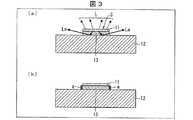
図3は、図1に示される発光ユニット1の効果を説明するための断面図であって、(a)は透明材料膜13が発光部11から出射された光を導光するモデルを示し、(b)は透明材料膜13が露出していない構成の発光ユニットを示す。≪Explanation of effects of light emitting unit 1≫
FIG. 3 is a cross-sectional view for explaining the effect of the light emitting unit 1 shown in FIG. 1, wherein (a) shows a model in which the
(導光モデル)
図3の(a)に示されるように、発光部11の励起光照射面S側から、蛍光Lが出射する。さらに、発光部11の励起光照射面Sとは反対側の面から、蛍光Laが出射する。この蛍光Laは、透明材料膜13の内部を伝搬し、外部へ出射する。つまり、透明材料膜13は、蛍光Laの導波路として機能する。(Light guide model)
As shown in FIG. 3A, the fluorescence L is emitted from the excitation light irradiation surface S side of the
以上のように、蛍光Lに加え、蛍光Laが発光ユニット1の外部へ出射するため、発光ユニット1を備えた発光装置の蛍光利用効率は、従来よりも高くなる。 As described above, since fluorescence La is emitted to the outside of the light emitting unit 1 in addition to the fluorescence L, the fluorescence utilization efficiency of the light emitting device including the light emitting unit 1 is higher than before.
(導光モデルの妥当性)
図3の(b)に示されるように、透明材料膜13の端部Aに遮光部材aを設けると、発光ユニット1の蛍光利用効率は、透明材料膜13の端部Aが露出されている場合よりも下がることを、本発明の発明者らは実験によって確認している。つまり、図3の(a)に示される導光モデルは妥当であることが、実験によって証明されている。(Relevance of light guide model)
As shown in FIG. 3B, when the light shielding member a is provided at the end A of the
≪発光ユニット1の効果をより高める構成≫
(透明材料膜13の面積)
発光部11の励起光照射面Sの面積(以下「発光面積」)と、透明材料膜13の、発光部11と対向する面の面積(以下「導光面積」)とは、同程度であることが好ましい。導光面積が、発光面積よりも大きければ、実質的な発光源のサイズは、導光面積で規定されるため、発光面積よりも大きくなるとともに、発光点が見かけ上複数(励起光照射面Sと透明材料膜11の端部A)存在してしまう可能性がある。≪Configuration that enhances the effect of light-emitting unit 1≫
(Area of transparent material film 13)
The area of the excitation light irradiation surface S of the light emitting unit 11 (hereinafter referred to as “light emitting area”) and the area of the surface of the
発光面積と導光面積とをほぼ同じ面積とすることにより、発光部11から出射する蛍光L(図3の(a)参照)の出射位置と、透明材料膜13の端部Aから出射する蛍光Laの出射位置とが、概ね同一位置であるとみなせるため、発光ユニット1を光学的に扱いやすくなる(例えば、投光部材が有する焦点に対して発光部11の位置を決めやすくなる)。 By making the light emission area and the light guide area substantially the same area, the emission position of the fluorescence L (see FIG. 3A) emitted from the
さらに、発光ユニット1の実質的な発光源のサイズを小さくできる。ここで、発光ユニット1の実質的な発光源のサイズは、発光している部分の最外部によって決まる。このため、導光面積は、発光ユニット1の実質的な発光源のサイズとなる。当該発光源のサイズが小さいほど、小さな投光部材(レンズ・反射鏡など)で所望の投光が可能となるなど、光学的にはより好ましいと言える。 Furthermore, the size of the substantial light source of the light emitting unit 1 can be reduced. Here, the substantial size of the light source of the light emitting unit 1 is determined by the outermost part of the light emitting part. For this reason, the light guide area is the size of the substantial light source of the light emitting unit 1. It can be said that the smaller the size of the light emitting source, the more optically preferable that a desired light can be projected with a small light projecting member (lens, reflector, etc.).
(レーザ光Eが照射される面積)
レーザ光Eは、発光部11の励起光照射面Sの全面に照射されることが好ましい。(Area irradiated with laser beam E)
The laser beam E is preferably irradiated on the entire excitation light irradiation surface S of the
レーザ光Eが、発光部11の一部(例えば発光部11の中央)のみに照射された場合、レーザ光Eの照射を受けた発光部11の一部のみが発光する。このとき、発光ユニット1を励起光照射面Sの法線方向側から見た場合、発光部11の発光部位と、透明材料膜13の端部Aとの二箇所が、別々の発光部位として観測される。つまり、発光ユニット1は、見かけ上、複数の発光点を有することになる。 When the laser light E is applied to only a part of the light emitting unit 11 (for example, the center of the light emitting unit 11), only a part of the
しかし、レーザ光Eが、発光部11の励起光照射面Sの全面に照射される場合、発光ユニット1の正面から出射される光(図3の(a)に示される蛍光L)と、発光ユニット1の側面から出射される光(図3の(a)に示される蛍光La)とは、一点から出射した光として観測される。つまり、発光ユニット1は、一つの発光点を有する発光源となる。 However, when the laser light E is irradiated on the entire surface of the excitation light irradiation surface S of the
そのため、単一の発光点を有する、点光源に好適な光源を実現できる。 Therefore, a light source suitable for a point light source having a single light emitting point can be realized.
なお、発光ユニット1の発光点が単一であると見なせるようにするために、厳密に励起光照射面Sの全面にレーザ光Eを照射する必要は必ずしもない。レーザ光が、励起光照射面Sの概ね全面(例えば、95%以上)に照射される場合でも、発光ユニット1の正面から出射される光と、発光ユニット1の側面から出射される光とを、一つの発光源由来の光としてみなせることがある。よって、レーザ光が励起光照射面Sの概ね全面に照射される構成も、本発明に含まれる。また、レーザ光が励起光照射面Sよりも広い範囲に照射されてもよい。 It is not always necessary to irradiate the entire surface of the excitation light irradiation surface S with the laser light E so that the light emitting unit 1 can be regarded as having a single light emitting point. Even when the laser light is irradiated on almost the entire surface (for example, 95% or more) of the excitation light irradiation surface S, the light emitted from the front surface of the light emitting unit 1 and the light emitted from the side surface of the light emitting unit 1 are used. , It can be regarded as light from one light source. Therefore, the present invention also includes a configuration in which the laser beam is irradiated on substantially the entire excitation light irradiation surface S. Further, the laser beam may be irradiated in a wider range than the excitation light irradiation surface S.
(透明材料膜13の屈折率)
透明材料膜13の屈折率は、発光部11の平均屈折率よりも高いことが好ましい。(Refractive index of transparent material film 13)
The refractive index of the
ここで、平均屈折率とは、部材(発光部11または透明材料膜13)が含む各物質の屈折率を、物質の部材に対する体積含有率(含有された粒子間に空隙がある場合には、この空隙の割合も考慮)に基づいて加重平均した値である。 Here, the average refractive index refers to the refractive index of each substance included in the member (the
YAG蛍光体の屈折率は、1.83程度である。CASN蛍光体の屈折率は、2.0程度である。低融点ガラスの屈折率は、1.47〜1.5程度である。そして、発光部11は、YAG蛍光体とCASN蛍光体とを所定の割合で混合したものを低融点ガラスで封止したものであり、発光部11の平均的屈折率は、1.65程度である。一方、透明材料膜13は、酸化アルミニウム(いわゆる、アルミナ)を含むため、透明材料膜13の屈折率は、1.76程度である。 The refractive index of the YAG phosphor is about 1.83. The refractive index of the CASN phosphor is about 2.0. The refractive index of the low-melting glass is about 1.47 to 1.5. The
このように、透明材料膜13の平均屈折率が、発光部11の平均屈折率よりも高くなる場合、発光部11から透明材料膜13に入射した光は、透明材料膜13に閉じ込められやすくなる。そのため、透明材料膜13に入射した光を、横方向(端部Aへ向かう方向)により確実に導波することができる。 As described above, when the average refractive index of the
(透明材料膜13の膜厚)
透明材料膜13の膜厚は、0.1μm以上10μm以下であることが好ましい。(Thickness of the transparent material film 13)
The film thickness of the
透明材料膜13の好ましい膜厚の上限値は、透明材料膜13が含む材料や、発光ユニット1の使用形態(例えば、発光部11の発熱量)に依存する。そして、透明材料膜13の膜厚が大きくなるほど、透明材料膜13を介し発光部11から基板12へ放熱される熱量が少なくなる。膜厚が10μm以下である場合、透明材料膜13は、発光部11が発した熱を充分に基板12へ伝えることができる。 The upper limit value of the preferable film thickness of the
また、透明材料膜13の好ましい膜厚の下限値は、透明材料膜13が含む材料や、透明材料膜13の上下に配される部材が含む材料の、光学物性値に依存する。そして、透明材料膜13の膜厚が小さくなるほど、透明材料膜13が導光する光量は少なくなる。膜厚が0.1μm以上である場合、透明材料膜13は、光を充分に導光できる。つまり、透明材料膜13をコアとしたスラブ導波路として機能する。 Further, the lower limit value of the preferable film thickness of the
≪発光ユニット1を利用したヘッドライト5の構成≫
上述の発光ユニット1を、例えば自動車のヘッドライト用の光源として利用できる。<< Configuration of headlight 5 using light emitting unit 1 >>
The light emitting unit 1 described above can be used as a light source for a headlight of an automobile, for example.
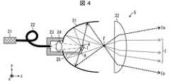
図4は、図1に示される発光ユニット1を利用したヘッドライト5(発光装置、照明装置、車両用前照灯)の構成を示す断面図である。 FIG. 4 is a cross-sectional view showing a configuration of a headlight 5 (light emitting device, lighting device, vehicle headlamp) using the light emitting unit 1 shown in FIG.
図4に示されるように、ヘッドライト5は、レーザ素子21(励起光源)と、光ファイバー22と、筐体23と、凸レンズ24と、支持台25と、発光ユニット1と、投光部材として凹面鏡31(反射鏡)と、凸レンズ32とを備える。 As shown in FIG. 4, the headlight 5 includes a laser element 21 (excitation light source), an
(レーザ素子21)
レーザ素子21は、波長450nm(青色)・出力4Wのレーザ光を出射する半導体レーザ素子である。レーザ素子21は、放熱用のヒートシンク(非図示)に取り付けられている。また、レーザ素子21は、駆動用の電源回路(非図示)に接続されている。(Laser element 21)
The
(光ファイバー22)
光ファイバー22は、断面が長方形のコアを有するマルチモード光ファイバーである。光ファイバー22の一端は、レーザ素子21の発光点に接続されている。また、光ファイバー22の他端は、筐体23に接続されている。レーザ素子21が出射したレーザ光は、光ファイバー22を介して筐体23の内部まで伝搬する。(Optical fiber 22)
The
(筐体23・凸レンズ24)
筐体23は、凹面鏡31の底部(Z軸負方向側の部分)の外面に接続されている。(
The
凸レンズ24は、筐体23の内部に備えられている。そして、凸レンズ24は、光ファイバー22から出射したレーザ光を、発光ユニット1の発光部11の励起光照射面Sの全面に結像する。 The
(支持台25)
支持台25は、発光ユニット1を支持する台である。支持台25の一端は、凹面鏡31の底部の内面に接続されている。支持台25の他端は、発光ユニット1が所望の姿勢(発光ユニット1の透明材料膜13の端部Aが、凹面鏡31の反射面の一部に対向する姿勢)となるように、発光ユニット1を支持している。支持台25の材料は、発光ユニット1が発する熱を熱伝導により放熱できるように、アルミニウムまたはセラミックスなどの、高熱伝導性材料であることが好ましい。(Support stand 25)
The
(凹面鏡31・凸レンズ32)
凹面鏡31は、回転楕円体の一部をベースにした凹面鏡である。そして、回転楕円体は、焦点を二つ有する。発光ユニット1は、回転楕円体の第一焦点に配されている。よって、発光ユニット1が出射した光は、凹面鏡31で反射された後、概ね回転楕円体の第二焦点Fに集光される。(
The
凸レンズ32は、第二焦点Fに集光された光を、Z軸正方向側へ投光する。 The
≪ヘッドライト5の動作および効果≫
ヘッドライト5は、以下のように動作する。
・図4に二点鎖線で示されるように、青色(波長450nm)のレーザ光が、発光ユニット1の発光部11の励起光照射面Sの全面に照射される。
・図4に細い破線で示されるように、発光ユニット1の発光部11から出射した、黄色の蛍光(図3の(a)に示される蛍光L)と、青色のレーザ光とが混色した白色光が、照明光Iとして投光される。
・図4に太い破線で示されるように、発光ユニット1の透明材料膜13の端部Aから出射した、黄色の蛍光(図3の(a)に示される蛍光La)と、青色のレーザ光とが混色した白色光が、照明光Iaとして投光される。<< Operation and effect of headlight 5 >>
The headlight 5 operates as follows.
As shown by a two-dot chain line in FIG. 4, blue (wavelength 450 nm) laser light is irradiated on the entire surface of the excitation light irradiation surface S of the
As shown by a thin broken line in FIG. 4, a white color in which yellow fluorescent light (fluorescent light L shown in FIG. 3A) emitted from the
As shown by a thick broken line in FIG. 4, yellow fluorescence (fluorescence La shown in FIG. 3A) and blue laser light emitted from the end A of the
以上の動作により、従来では発光部11から出射された後に発光部11へ戻り発光部11の外部へ投光されなかった蛍光の一部(照明光Ia)が、透明材料膜13を介し発光部11の外部へ投光される。 With the above operation, a part of the fluorescence (illumination light Ia) that has been conventionally emitted from the
〔実施形態2〕
本発明の第二実施形態について、図5〜図6に基づいて説明すれば、以下のとおりである。なお、説明の便宜上、上述の実施形態にて説明した部材と同じ機能を有する部材については、同じ符号を付記し、その説明を省略する。[Embodiment 2]
It will be as follows if 2nd embodiment of this invention is described based on FIGS. For convenience of explanation, members having the same functions as those described in the above-described embodiment are denoted by the same reference numerals and description thereof is omitted.
≪発光ユニット1aの製造方法≫
図5は、本実施形態の発光ユニット1aの製造方法を示す図であって、(a)〜(b)は発光ユニット1aを製造する過程を示す断面図であり、(c)は(b)の上面図であり、(d)は製造された発光ユニット1aを示す断面図である。<< Manufacturing Method of
FIG. 5 is a view showing a method for manufacturing the
図5の(a)に示されるように、基板12の一面の全体に、例えば、二酸化チタン(TiO2)膜を真空蒸着し、透明材料膜13aを形成する。透明材料膜13aの膜厚は、例えば、0.3μmである。透明材料膜13aの屈折率は、2.5〜2.7程度である。As shown in FIG. 5A, for example, a titanium dioxide (TiO2 ) film is vacuum-deposited on the entire surface of the
図5の(b)〜(c)に示されるように、透明材料膜13aは、例えば、フォトリソグラフィとウエットエッチングとにより円形にパターン形成される。 As shown in FIGS. 5B to 5C, the
図5の(d)に示されるように、YAG蛍光体を含むペーストを、例えば、スクリーン印刷により円形の透明材料膜13aの上に塗布し、発光部11aを形成する。ここで、透明材料膜13aの端部Aが露出するように、透明材料膜13aの位置に合わせて発光部11aを形成する。 As shown in FIG. 5D, a paste containing a YAG phosphor is applied onto the circular
以上のように、発光部11aと、基板12と、透明材料膜13aとを備えた発光ユニット1aを製造できる。 As described above, the
発光ユニット1aでは、波長450nmのレーザ光が、発光部11aの励起光照射面Sの全面に照射されることにより、発光部11a中のYAG蛍光体が励起されて蛍光を発する。 In the
上述の発光ユニット1では、発光部11は、ダイシングを利用しているため、直線状に成形された。しかし、発光ユニット1aでは、発光部11は、任意の形状(例えば円形)に成形され得る。 In the light emitting unit 1 described above, the
≪発光ユニット1aを利用したヘッドライト5aの構成≫
図6は、図5の(d)に示される発光ユニット1aを利用したヘッドライト5a(発光装置、照明装置、車両用前照灯)の構成を示す断面図である。<< Configuration of
FIG. 6 is a cross-sectional view showing a configuration of a
図6に示されるように、ヘッドライト5aは、レーザ素子21と、光ファイバー22aと、筐体23と、凸レンズ24と、支持台25aと、発光ユニット1aと、投光部材として凹面鏡31a(反射鏡)とを備える。 As shown in FIG. 6, the
(光ファイバー22a)
光ファイバー22aは、光ファイバー22と同様の機能を備える。しかし、光ファイバー22aのコアの断面形状は、光ファイバー22のコアの断面形状とは異なり、円形である。これにより、発光ユニット1aの円形の発光部11aに、円形のレーザ光を照射できる。(
The
(支持台25a)
支持台25aは、支持台25とは異なり、発光ユニット1aの透明材料膜13aの端部Aが、xy平面が伸びる方向(凹面鏡31aの中心軸に垂直な方向)へ向くように、発光ユニット1aを支持している。(
Unlike the
(凹面鏡31a)
凹面鏡31aは、凹面鏡31とは異なり、回転放物面の一部をベースにした凹面鏡である。そして、回転放物面は、回転放物面の内部に焦点を一つ有する。発光ユニット1aは、回転放物面の焦点に配されている。よって、発光ユニット1aが出射した光は、凹面鏡31aに反射された後、概ね平行光として投光される。(
Unlike the
≪ヘッドライト5aの動作および効果≫
ヘッドライト5aは、以下に列挙するように動作する。
・図6に二点鎖線で示されるように、青色(波長450nm)のレーザ光が、発光ユニット1aの発光部11aの励起光照射面Sの全面に照射される。
・図6に細い破線で示されるように、発光ユニット1aの発光部11aから出射した、黄色の蛍光と、青色のレーザ光とが混色した白色光が、照明光Iとして投光される。
・図6に太い破線で示されるように、発光ユニット1aの透明材料膜13aの端部Aから出射した、黄色の蛍光と、青色のレーザ光とが混色した白色光が、照明光Iaとして投光される。<< Operation and effect of
The
As shown by a two-dot chain line in FIG. 6, blue (wavelength 450 nm) laser light is irradiated on the entire surface of the excitation light irradiation surface S of the
As shown by a thin broken line in FIG. 6, white light emitted from the
As shown by a thick broken line in FIG. 6, white light emitted from the end A of the
以上の動作により、従来では発光部11aから出射された後に発光部11aへ戻り発光部11aの外部へ投光されなかった蛍光の一部(照明光Ia)が、透明材料膜13aを介し発光部11aの外部へ投光される。 According to the above operation, a part of the fluorescence (illumination light Ia) that has been conventionally emitted from the
また、ヘッドライト5aが投光する照明光の形状は、発光ユニット1aの発光部11aの形状と同様に、円形になる。上述のように、発光部11aの形状は任意形状に加工できるため、ヘッドライト5aは、任意形状の照明光を投光できる。 Moreover, the shape of the illumination light projected by the
さらに、発光ユニット1aが、発光ユニット1aの投光部材である凹面鏡31aの内部に配され、発光ユニット1aの透明材料膜13aの端部Aが、凹面鏡31aの中心軸と垂直な方向へ向けられることで、すべての端部Aが、確実に凹面鏡31aの反射面の一部に対向できる。これにより、ヘッドライト5aでは、従来では発光部11aから出射された後に発光部11aへ戻り発光部11aの外部へ投光されなかった蛍光の一部が、透明材料膜13aを介し発光部11aの外部へ確実に投光される。 Further, the
〔実施形態3〕
本発明の第三実施形態について、図7〜図8に基づいて説明すれば、以下のとおりである。なお、説明の便宜上、上述の実施形態にて説明した部材と同じ機能を有する部材については、同じ符号を付記し、その説明を省略する。[Embodiment 3]
It will be as follows if 3rd embodiment of this invention is described based on FIGS. For convenience of explanation, members having the same functions as those described in the above-described embodiment are denoted by the same reference numerals and description thereof is omitted.
≪発光ユニット1bの製造方法≫
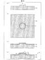
図7は、本実施形態の発光ユニット1bの製造方法を示す図であって、(a)〜(b)は発光ユニット1bを製造する過程を示す断面図であり、(c)は(b)の上面図であり、(d)は製造された発光ユニット1bを示す断面図である。<< Manufacturing Method of
FIG. 7 is a view showing a method for manufacturing the
図7の(a)に示されるように、基板12の一面の全体に、例えば、アルミニウム(Al)や銀(Ag)などをコーティングしコーティング層121(支持部材)を形成する。このように、基板12は、コーティング層121を有してよい。 As shown in FIG. 7A, the entire surface of the
図7の(b)〜(c)に示されるように、例えば、ガラスフリット含有ペーストを印刷により正方形に形成し、ベーキングによりガラスフリットを溶融して、冷却することにより硬化させ、ガラス膜13b(透明材料膜)を形成する。ガラス膜13bの厚さは、例えば、10μmである。ガラス膜13bの屈折率は、1.5〜1.6程度とした。 As shown in FIGS. 7B to 7C, for example, a glass frit-containing paste is formed into a square by printing, the glass frit is melted by baking, and is cured by cooling to form a
図7の(d)に示されるように、CASN蛍光体と、セリウム(Ce)賦活αサイアロン(SiAlON;Silicon Aluminium Oxygen Nitrogen)蛍光体とが混合されてシリコーン樹脂に封止されたものをガラス膜13b上に形成し、発光部11bを形成する。ここで、ガラス膜13bの端部Aが露出するように、ガラス膜13bの位置に合わせて蛍光体板をガラス膜13b上に貼り付けた。そして、発光部11bの平均屈折率を1.45程度とした。 As shown in FIG. 7 (d), a glass film is prepared by mixing a CASN phosphor and a cerium (Ce) activated α sialon (SiAlON) phosphor and sealing it with a silicone resin. 13b is formed to form the
以上のように、発光部11bと、基板12と、コーティング層121と、ガラス膜13bとを備えた発光ユニット1bを製造できる。 As described above, the
≪発光ユニット1bを利用したヘッドライト5bの構成≫
図8は、図7の(d)に示される発光ユニット1bを利用したヘッドライト5b(発光装置、照明装置、車両用前照灯)の構成を示す断面図であって、(a)は全体図を示し、(b)は発光ユニット1b周辺の拡大図を示す。<< Configuration of
FIG. 8 is a cross-sectional view showing the configuration of a
図8の(a)に示されるように、ヘッドライト5bは、導光部材22bと、筐体23bと、凸レンズ24と、発光ユニット1bと、投光部材として上部筐体31bと、波長選択ミラー33と、透明部材34と、凸レンズ32とを備える。また、図示されていないが、ヘッドライト5bは、励起光としてのレーザ光Eを出射する半導体レーザ素子も備えている。 As shown in FIG. 8A, the
(導光部材22b)
導光部材22bは、角柱形状の光学ロッドであり、その断面形状は、光ファイバー22のコアの断面形状とは異なり、正方形である。これにより、発光ユニット1bの発光部11bに、正方形のスポットとしてレーザ光Eを照射できる。また、導光部材22bの材質は、ガラスである。(
The
この導光部材22bの一方の端部は、後述する筐体23bの内部経路内に挿入されており、上記半導体レーザ素子から出射されたレーザ光Eを上記内部経路内に導光する。 One end of the
(筐体23b・上部筐体31b・凸レンズ24)
ヘッドライト5bにおいて発光ユニット1bを収納する筐体は、筐体23bおよび上部筐体31bから構成される。筐体23bの、上部筐体31bと接する面(接合面と称する)に、発光ユニット1bのコーティング層121と基板12とが埋め込まれている。発光ユニット1bの発光部11bとガラス膜13bとは、上記接合面より突出しており、上部筐体31bに形成された、照明光を投光するための投光空間の内部において露出している。(
The housing that houses the
上部筐体31bには、上記投光空間を形成する空洞部が形成されており、この空洞部の表面である内壁Kは、光を反射する鏡面になっている。 The
図8の(b)に示されるように、発光ユニット1bのガラス膜13bの端部Aは、内壁Kに対向している。さらに、内壁Kは、端部Aから光が出射される方向に対して傾斜しており、端部Aから出射した光を受け所望の方向(凸レンズ32の方向)へ投光できる。 As shown in FIG. 8B, the end A of the
また、筐体23bおよび上部筐体31bには、導光部材22bから出射されたレーザ光を通過させる内部経路が形成されている。凸レンズ24は、筐体23bの内部に形成された内部経路内に配置されている。そして、この凸レンズ24は、導光部材22bから出射したレーザ光Eを集光し、波長選択ミラー33に照射する。 In addition, an internal path through which the laser light emitted from the
(波長選択ミラー33)
波長選択ミラー33は、発光部11bの励起光照射面Sに対向して配置された透光性を有する多層膜コーティング層である。波長選択ミラー33は、透明部材34の一方の面に真空蒸着法やスパッタ法などで形成された薄膜層であり、発光部11bの励起光照射面Sに対向して略平行に配置されている。(Wavelength selection mirror 33)
The
この波長選択ミラー33は、上記内部経路を通過したレーザ光Eを反射させる一方、発光部11bが発する蛍光を透過させる。すなわち、波長選択ミラー33は、レーザ光Eを反射させ、且つ、発光部11bが発する蛍光を透過させるという、波長選択性を有している。 The
(透明部材34)
透明部材34は、発光部11bが発する蛍光を透過し、かつ、その表面に波長選択ミラー33が形成された基板である。換言するならば、透明部材34は、波長選択ミラー33として機能する多層膜コーティング層を支持する透明部材である。透明部材34としては、例えば、BK7、合成石英、白板ガラス(例えば、B270、D263Teco、BSL7)などを好適に用いることができる。(Transparent member 34)
The
≪ヘッドライト5bの動作および効果≫
ヘッドライト5bは、以下に列挙するように動作する。
・図8の(a)に二点鎖線で示されるように、青紫色(波長405nm)のレーザ光Eが、発光ユニット1bの発光部11bの励起光照射面Sの全面に照射される。
・図8の(a)に細い破線で示されるように、発光ユニット1bの発光部11bから出射した、赤色の蛍光と青緑色の蛍光とが混色した白色光が、照明光Iとして投光される。
・図8の(a)に太い破線で示されるように、発光ユニット1bのガラス膜13bの端部Aから出射した、赤色の蛍光と青緑色の蛍光とが混色した白色光が、照明光Iaとして投光される。<< Operation and effect of
The
As shown by the two-dot chain line in FIG. 8A, the entire surface of the excitation light irradiation surface S of the
As shown by a thin broken line in FIG. 8A, white light emitted from the
As shown by a thick broken line in FIG. 8A, white light emitted from the end A of the
以上の動作により、従来では発光部11bから出射された後に発光部11bへ戻り発光部11bの外部へ投光されなかった蛍光の一部(照明光Ia)が、ガラス膜13bを介し発光部11bの外部へ投光される。 Through the above operation, a part of the fluorescence (illumination light Ia) that has been conventionally emitted from the
〔実施形態4〕
本発明の第四実施形態について、図9〜図10に基づいて説明すれば、以下のとおりである。なお、説明の便宜上、上述の実施形態にて説明した部材と同じ機能を有する部材については、同じ符号を付記し、その説明を省略する。[Embodiment 4]
It will be as follows if 4th embodiment of this invention is described based on FIGS. For convenience of explanation, members having the same functions as those described in the above-described embodiment are denoted by the same reference numerals and description thereof is omitted.
≪発光ユニット1cの製造方法≫
図9は、本実施形態の発光ユニット1cの製造方法を示す図であって、(a)および(c)は発光ユニット1cを製造する過程を示す断面図であり、(b)は(a)の上面図であり、(d)は製造された発光ユニット1cを示す断面図である。<< Manufacturing Method of Light Emitting Unit 1c >>
FIG. 9 is a view showing a method for manufacturing the light emitting unit 1c of the present embodiment, in which (a) and (c) are cross-sectional views showing a process of manufacturing the light emitting unit 1c, and (b) is (a). (D) is sectional drawing which shows the manufactured light emission unit 1c.
図9の(a)〜(b)に示されるように、基板12c(支持部材)は、例えば、表面に円形の凸部Hが設けられたアルミニウム基板である。 As shown in FIGS. 9A to 9B, the
図9の(c)に示されるように、基板12cの一面の全体に、例えば、スパッタ法により、二酸化ケイ素(SiO2)膜である透明材料膜13cを形成する。透明材料膜13cの膜厚は、例えば、0.1μmである。透明材料膜13cの屈折率は、1.46程度になる。As shown in FIG. 9C, a
図9の(d)に示されるように、ユーロピウム(Eu)賦活αSiAlON蛍光体とβSiAlON蛍光体とを混合した蛍光体ペーストをディスペンサにより基板12cの凸部Hに塗布(シリコーンポッティング)し、ベーキングを行うことで発光部11cを形成する。このとき、凸部Hの斜面部Acには発光部11cが形成されないようにした。 As shown in FIG. 9 (d), a phosphor paste obtained by mixing europium (Eu) activated αSiAlON phosphor and βSiAlON phosphor is applied to the convex portion H of the
ここで、斜面部Acは、透明材料膜13cの露出した端部であると見なすことができる。そして、発光部11cから出射された蛍光の一部は、透明材料膜13cに入射し、斜面部Acまで導光される。導光された蛍光は、斜面部Acから出射する。 Here, the slope portion Ac can be regarded as an exposed end portion of the
以上のように、発光部11cと、基板12cと、透明材料膜13cとを備えた発光ユニット1cを製造できる。 As described above, the light emitting unit 1c including the
発光ユニット1cでは、波長450nmのレーザ光が、発光部11cの励起光照射面Sの全面に照射されることにより、発光部11c中のEu賦活αSiAlON蛍光体とβSiAlON蛍光体とが励起されて蛍光を発する。 In the light emitting unit 1c, laser light having a wavelength of 450 nm is irradiated on the entire surface of the excitation light irradiation surface S of the
≪発光ユニット1cを利用したスポットライト5cの構成≫
図10は、図9の(d)に示される発光ユニット1cを利用したスポットライト5c(発光装置、照明装置)の構成を示す断面図である。<< Configuration of
FIG. 10 is a cross-sectional view showing a configuration of a
図10に示されるように、スポットライト5cは、レーザ素子21と、凸レンズ24と、折り返しミラー26と、発光ユニット1cと、投光部材として凹面鏡31c(反射鏡)とを備える。 As shown in FIG. 10, the
(折り返しミラー26)
折り返しミラー26は、レーザ素子21から出射し凸レンズ24を透過した光を、発光ユニット1c励起光照射面Sの全面へ反射・集光する。(Folding mirror 26)
The
(凹面鏡31c)
凹面鏡31cは、凹面鏡31とは異なり、回転放物面の一部をベースにした凹面鏡(つまり、すり鉢形状)である。そして、回転放物面は、回転放物面の内部に焦点を一つ有する。発光ユニット1cは、発光ユニット1cの発光部11cが当該焦点に配されるように、回転放物面の底部(Z軸負方向側の部位)に配されている。よって、発光ユニット1aが出射した光は、凹面鏡31cに反射された後、概ね平行光として投光される。(
Unlike the
≪スポットライト5cの動作および効果≫
スポットライト5cは、以下に列挙するように動作する。
・図10に二点鎖線で示されるように、青色(波長450nm)のレーザ光が、発光ユニット1cの発光部11cの励起光照射面Sの全面に照射される。
・図10に細い破線で示されるように、発光ユニット1cの発光部11cから出射した、赤色および緑色の蛍光と、青色のレーザ光とが混色した白色光が、照明光Iとして投光される。
・図10に太い破線で示されるように、発光ユニット1cの透明材料膜13cの端部Aから出射した、赤色および緑色の蛍光と、青色のレーザ光とが混色した白色光が、照明光Iaとして投光される。<< Operation and effect of
The
As shown by the two-dot chain line in FIG. 10, blue (wavelength 450 nm) laser light is irradiated on the entire surface of the excitation light irradiation surface S of the
As shown by a thin broken line in FIG. 10, white light emitted from the
As shown by a thick broken line in FIG. 10, white light, which is emitted from the end A of the
以上の動作により、従来では発光部11cから出射された後に発光部11cへ戻り発光部11cの外部へ投光されなかった蛍光の一部(照明光Ia)が、透明材料膜13cを介し発光部11cの外部へ投光される。 With the above operation, a part of the fluorescence (illumination light Ia) that has been conventionally emitted from the
〔実施形態5〕
本発明の第五実施形態について、図11〜図13に基づいて説明すれば、以下のとおりである。なお、説明の便宜上、上述の実施形態にて説明した部材と同じ機能を有する部材については、同じ符号を付記し、その説明を省略する。[Embodiment 5]
The fifth embodiment of the present invention will be described below with reference to FIGS. For convenience of explanation, members having the same functions as those described in the above-described embodiment are denoted by the same reference numerals and description thereof is omitted.
≪発光ユニット1dの製造方法≫
図11は、本実施形態の発光ユニット1dの製造方法を示す断面図であって、(a)〜(c)は発光ユニット1dを製造する過程を示し、(d)は製造された発光ユニット1dを示す。<< Manufacturing Method of
FIG. 11 is a cross-sectional view showing a method for manufacturing the
図11の(a)〜(b)に示されるように、基板12の一面の全体に、例えば、スパッタ法により、二酸化ケイ素(SiO2)膜を下層(基板12に接する層)とし、二酸化チタン(TiO2)膜を上層(下層の上に積層される層)とした二種類の誘電体膜を含む透明材料膜13dを形成する。As shown in FIGS. 11A to 11B, a silicon dioxide (SiO2 ) film is formed as a lower layer (a layer in contact with the substrate 12) by sputtering, for example, over the entire surface of the
二酸化ケイ素膜の屈折率は、1.46程度である。また、二酸化チタン膜の屈折率は、2.5〜2.7程度である。 The refractive index of the silicon dioxide film is about 1.46. The refractive index of the titanium dioxide film is about 2.5 to 2.7.
図11の(c)に示されるように、CASN蛍光体を含む蛍光体分散液を透明材料膜13dの一面の全面に沈降させた下層と、βSiAlON蛍光体を含む蛍光体分散液を当該下層の一面の全体に沈降させた中層と、BAM(Eu賦活BaMgAl10O17)蛍光体を含む蛍光体分散液を当該中層の一面の全面に沈降させた上層とを、順に積層させ積層体10dを形成する。そして、積層体10dをベーキングし、発光部11dを形成する。As shown in FIG. 11 (c), a lower layer in which a phosphor dispersion liquid containing CASN phosphor is precipitated on the entire surface of one surface of the
図11の(d)に示されるように、スクライブにより積層体10dに溝14を形成する(溝ストライプ)。溝14は、発光部11dの励起光照射面Sから基板12まで達するように設けられる。また、溝14は、発光部11dの励起光照射面Sが例えば正方形になるように(正方形の四辺に相当する位置に)、設けられる。 As shown in FIG. 11D,
以上のように、発光部11dと、基板12と、透明材料膜13dとを備えた発光ユニット1dを製造できる。 As described above, the
(発光ユニット1dの効果)
発光部11dが発した蛍光の一部は、基板12で反射するときに、基板12により吸収される(蛍光の吸収)。しかし、透明材料膜13dを2層以上の多層構造とし、これらの層において、基板12側の層(以下「下層132」)の屈折率を、発光部11d側の層(以下「上層131」)の屈折率よりも低くすることにより、下層132から基板12へ向かって蛍光が出射することを防止できる。そのため、発光部11dが発した蛍光の一部を、透明材料膜13dの端部Aから効率的に取り出すことができる。(Effect of
A part of the fluorescence emitted by the
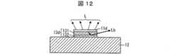
図12は、図11に示される発光ユニット1dの効果を説明するための断面図である。 FIG. 12 is a cross-sectional view for explaining the effect of the
図12に示されるように、透明材料膜13dが、上層131(主層)と、上層131よりも屈折率が低い下層132(第一の補助層)とを備えるとき、発光部11dが上層131の中へ発した蛍光Lbは、上層131から下層132を介して基板12に向かって出射し、基板12に反射されることが少なくなる(蛍光吸収の抑制)。そのため、蛍光Lbは、上層131によって導波される割合が多くなる。 As shown in FIG. 12, when the
以上のように、透明材料膜13dが単層である構成よりも、発光部11dが発する蛍光の利用効率を高めることができる。 As described above, the use efficiency of the fluorescence emitted by the
≪発光ユニット1dを利用した照明器具用光源5dの構成≫
図13は、図11の(d)に示される発光ユニット1dを利用した照明器具用光源5d(発光装置、照明装置)の構成を示す断面図である。<< Configuration of
FIG. 13 is a cross-sectional view showing a configuration of a lighting
図13に示されるように、照明器具用光源5dは、レーザ素子21d(励起光源)と、光ファイバー22と、筐体23dと、凸レンズ24と、折り返しミラー26dと、発光ユニット1dと、投光部材としてスリガラス35とを備える。 As illustrated in FIG. 13, the
(レーザ素子21d)
レーザ素子21dは、波長405nm(青紫色)のレーザ光を出射する半導体レーザ素子である。レーザ素子21dは、放熱用のヒートシンク(非図示)に取り付けられている。また、レーザ素子21は、駆動用の電源回路(非図示)に接続されている。(
The
(筐体23d・凸レンズ24・折り返しミラー26d)
筐体23dは、発光ユニット1d、凸レンズ24およびスリガラス35を支持する筐体である。発光ユニット1dの基板12は、筐体23dに埋め込まれている。発光ユニット1dの発光部11dと透明材料膜13dとは、筐体23dから露出している。(
The
この筐体23dには、光ファイバー22から出射したレーザ光を通過させる内部経路が形成されている。凸レンズ24は、筐体23dの上記内部経路内に備えられている。そして、凸レンズ24は、光ファイバー22から出射したレーザ光を発光ユニット1dの発光部11dの励起光照射面Sの全面に結像する。 An internal path through which the laser light emitted from the
折り返しミラー26dは、レーザ素子21dから出射し凸レンズ24を透過した光を、発光ユニット1dの発光部11dの励起光照射面Sの全面へ反射・集光する。 The
(スリガラス35)
スリガラス35は、中空の球体状のガラス部材である。そして、発光ユニット1dの発光部11dと透明材料膜13dとは、スリガラス35により覆われている。そのため、照明器具用光源5dは、いわゆる電球状に発光する照明装置として機能する。(Ground glass 35)
The
発光ユニット1dの透明材料膜13dの端部Aから出射した蛍光は、スリガラス35を透過して外部に照明光Iaとして放出される。上述のように、発光部11dの透明材料膜13dが単層である構成よりも、発光部11dが発する蛍光の利用効率を高めることができるため、照明器具用光源5dの発光効率を高めることができる。 The fluorescence emitted from the end A of the
スリガラス35は、波長405nmの光に対する透過率が低く、かつ、発光部11dが発する蛍光に対する透過率が高い、UV(ultraviolet)カット部材であることが好ましい。これにより、発光部11dの表面で散乱された405nmのレーザ光は、スリガラス35にて吸収されるため、当該レーザ光の外部への放出が抑制される。 The
なお、スリガラス35の代わりに、透明または半透明の投光部材を用いてもよい。 Instead of the
(照明器具用光源5dの形状)
照明器具用光源5dの形状は、全体的に球体状であるがこの形状に限定されず、ライン状または平面状であってもよい。(Shape of
The shape of the lighting
≪照明器具用光源5dの動作および効果≫
照明器具用光源5dは、以下に列挙するように動作する。
・図13に二点鎖線で示されるように、青紫色(波長405nm)のレーザ光が、発光ユニット1dの発光部11dの励起光照射面Sの全面に照射される。
・図13に細い破線で示されるように、発光ユニット1dの発光部11dから出射した、白色光が、照明光Iとして投光される。上記白色光は、赤色の蛍光と、黄色の蛍光と、青色の蛍光とが発光部11dの内部で混色されることによって生成される。
・図13に太い破線で示されるように、発光ユニット1dの透明材料膜13dの端部Aから出射した、上記白色光が、照明光Iaとして投光される。<< Operation and Effect of
The lighting
As shown by a two-dot chain line in FIG. 13, blue-violet (wavelength 405 nm) laser light is irradiated on the entire surface of the excitation light irradiation surface S of the
As shown by a thin broken line in FIG. 13, white light emitted from the
As shown by a thick broken line in FIG. 13, the white light emitted from the end A of the
以上の動作により、従来では発光部11dから出射された後に発光部11dへ戻り発光部11dの外部へ投光されなかった蛍光の一部(照明光Ia)が、透明材料膜13dを介し発光部11dの外部へ投光される。 According to the above operation, a part of the fluorescence (illumination light Ia) that has been conventionally emitted from the
〔実施形態6〕
本発明の第六実施形態について、図14〜図15に基づいて説明すれば、以下のとおりである。なお、説明の便宜上、上述の実施形態にて説明した部材と同じ機能を有する部材については、同じ符号を付記し、その説明を省略する。[Embodiment 6]
The sixth embodiment of the present invention will be described below with reference to FIGS. For convenience of explanation, members having the same functions as those described in the above-described embodiment are denoted by the same reference numerals and description thereof is omitted.
≪発光ユニット1eの製造方法≫
図14は、本実施形態の発光ユニット1eの製造方法を示す断面図であって、(a)〜(c)は発光ユニット1eを製造する過程を示し、(d)は製造された発光ユニット1eを示す。≪Method for manufacturing
FIG. 14 is a cross-sectional view showing a method for manufacturing the
図14の(a)に示されるように、基板12e(支持部材)は、例えば、逆台形状の凸部Heが設けられたアルミニウム基板である。なお、基板12eの一面の全体に、例えば、銀(Ag)をコーティングしコーティング層(非図示)を形成してもよい。 As shown in FIG. 14A, the
図14の(b)〜(c)に示されるように、基板12eの一面側から、その全体に、例えば、スパッタ法により、第一の酸化アルミニウム(Al2O3)膜131e(第一の補助層)と、二酸化チタン(TiO2)膜132e(主層)と、第二の酸化アルミニウム(Al2O3)膜133e(第二の補助層)と(三層の誘電体膜)を記載の順に積層し、透明材料膜13eを形成する。As shown in FIGS. 14B to 14C, the first aluminum oxide (Al2 O3 )
第一の酸化アルミニウム膜131eの屈折率と、第二の酸化アルミニウム膜133eの屈折率とは、1.76程度である。また、二酸化チタン膜132eの屈折率は、2.5〜2.7程度である。 The refractive index of the first
凸部Heの透明材料膜13eに対向する面である凸面の面積は、当該凸面と平行な凸部Heの断面の面積よりも大きい。つまり、凸部Heの縦断面形状が逆台形状であるため、凸部Heの側面には、透明材料膜13eが堆積しない。そして、透明材料膜13eは、凸部Heの上部(中央部)と下部(周辺部)とに分かれ、不連続な構造となる。 The area of the convex surface, which is the surface facing the
図14の(d)に示されるように、YAG蛍光体とガラスフリットとを含有したペーストを凸部Heの上部に塗布しベーキングを行い、発光部11eを形成する。ここで、透明材料膜13eは不連続な構造であるため、発光部11eが形成された後でも、透明材料膜13aの端部Aは露出している。 As shown in FIG. 14D, a paste containing a YAG phosphor and glass frit is applied to the top of the convex portion He and baked to form the
以上のように、発光部11eと、基板12eと、透明材料膜13eとを備えた発光ユニット1eを製造できる。 As described above, the
(透明材料膜13eを三層の誘電体膜とすることの効果)
従来の発光ユニットでは、発光部から出射された蛍光の一部が、発光部と、発光部を支持する基板などの支持部材との界面で反射し、発光部へ戻る。蛍光は、レーザ光などの励起光とは異なり蛍光物質を励起できない。そして、発光部へ戻った蛍光は、発光部の内部で減衰する(蛍光の減衰)。(Effect of using
In the conventional light emitting unit, part of the fluorescence emitted from the light emitting unit is reflected at the interface between the light emitting unit and a support member such as a substrate that supports the light emitting unit, and returns to the light emitting unit. Fluorescence cannot excite a fluorescent substance, unlike excitation light such as laser light. And the fluorescence which returned to the light emission part attenuate | damps inside a light emission part (fluorescence attenuation | damping).
また、発光部が発した蛍光の一部は、発光部と支持部材との界面で反射するときに、支持部材により吸収される(蛍光の吸収)。 Further, part of the fluorescence emitted from the light emitting part is absorbed by the support member (fluorescence absorption) when reflected at the interface between the light emitting part and the support member.
しかし、高い屈折率の層へ入射した光は、低い屈折率の層へ出射し難い。よって、透明材料膜13eが、高い屈折率の層を低い屈折率の層で挟んだ三層の誘電体膜を含めば、上述の蛍光の減衰・蛍光の吸収が抑制され、発光部11eが発した蛍光の一部を、透明材料膜13e(特に、二酸化チタン膜)の端部から効率的に取り出すことができる。 However, light incident on the high refractive index layer is not easily emitted to the low refractive index layer. Therefore, if the
≪発光ユニット1eを利用した内視鏡用光源5eの構成≫
図15は、図14の(d)に示される発光ユニット1eを利用した内視鏡用光源5e(発光装置、照明装置)の構成を示す断面図である。<< Configuration of
FIG. 15 is a cross-sectional view showing a configuration of an
図15に示されるように、内視鏡用光源5eは、レーザ素子21と、筐体23と、凸レンズ24と、支持台25と、発光ユニット1eと、投光部材として凹面鏡31と、光ファイバー36とを備える。 As shown in FIG. 15, the
(レーザ素子21・筐体23)
レーザ素子21は、筐体23に形成された開口部に嵌め込まれている。レーザ素子21が出射したレーザ光は、筐体23の内部に直接出射される。そして、筐体23の内部に配された凸レンズ24は、レーザ素子21から出射したレーザ光を、発光ユニット1eの発光部11eの励起光照射面Sの全面に結像する。(
The
(凹面鏡31)
凹面鏡31は、発光部11eから出射された蛍光を配光制御し、その第二焦点Fに集光する光学部材である。上述のように、凹面鏡31は、回転楕円体の一部をベースにしているため、焦点を二つ有する。発光ユニット1eは、凹面鏡31の第一焦点に配置されており、発光ユニット1eから出射した蛍光は、凹面鏡31の第二焦点に集光される。この第二焦点に光ファイバー22eの一端(入射端)が配置されている。そのため、発光ユニット1eから出射した蛍光は、光ファイバー22eの入射端部のコアに集光され、光ファイバー22eの内部へ導光される。(Concave mirror 31)
The
そして、光は、凹面鏡31の第一焦点の近くから出射するほど、第二焦点の近くに集光される。ゆえに、発光ユニット1eが充分に小さければ、その全体を第一焦点の近くに配することも容易になるため、発光ユニット1eが発する光を、効率的に第二焦点(光ファイバー22eの入射端)の近くに集光できる。 The light is collected near the second focal point as it exits from the first focal point of the
(光ファイバー22e)
光ファイバー22eの一端は、上述のように凹面鏡31の形状をなす回転楕円体の第二焦点Fに配されている。発光ユニット1eが出射した光は、凹面鏡31で反射された後、第二焦点Fに位置する光ファイバー22eの入射端へ集光される。光ファイバー22eは、入射端から入射した光を、他端(出射端)へと導光し、図15におけるZ軸正方向側へ投光する。(Optical fiber 22e)
One end of the optical fiber 22e is disposed at the second focal point F of the spheroid forming the
≪内視鏡用光源5eの動作および効果≫
内視鏡用光源5eは、以下に列挙するように動作する。
・図15に二点鎖線で示されるように、青色(波長450nm)のレーザ光が、発光ユニット1eの発光部11eの励起光照射面Sの全面に照射される。
・図15に細い破線で示されるように、発光ユニット1eの発光部11eから出射した、黄色の蛍光と、青色のレーザ光とが混色した白色光が、照明光Iとして投光される。
・図15に太い破線で示されるように、発光ユニット1eの透明材料膜13eの端部Aから出射した、黄色の蛍光と、青色のレーザ光とが混色した白色光が、照明光Iaとして投光される。
・照明光I・Iaは、光ファイバー22eの一端(入射端)から投光される。<< Operation and effect of
The
As shown by a two-dot chain line in FIG. 15, blue (wavelength 450 nm) laser light is irradiated on the entire surface of the excitation light irradiation surface S of the
As shown by a thin broken line in FIG. 15, white light emitted from the
As shown by a thick broken line in FIG. 15, white light emitted from the end A of the
The illumination light I / Ia is projected from one end (incident end) of the optical fiber 22e.
以上の動作により、従来では発光部11eから出射された後に発光部11eへ戻り発光部11eの外部へ投光されなかった蛍光の一部(照明光Ia)が、透明材料膜13eを介し発光部11eの外部へ投光される。 By the above operation, a part of the fluorescence (illumination light Ia) that has been conventionally emitted from the
(レーザ光による励起と光ファイバーによる投光とを利用する構成の効果)
特に、図15に示されるように、発光ユニット1eから発せられる白色光を、光ファイバー22eの入射端に効率的に入射させるためには、発光ユニット1eの発光点のサイズは、光ファイバー22eのコアのサイズよりも小さいことが好ましい。(Effect of configuration using excitation by laser light and light projection by optical fiber)
In particular, as shown in FIG. 15, in order to make white light emitted from the
ここで、発光点が円形の場合には、発光点のサイズは、発光点の直径を意味する。また、発光点が矩形の場合には、発光点のサイズは、発光点の辺の長さを意味する。 Here, when the light emitting point is circular, the size of the light emitting point means the diameter of the light emitting point. When the light emitting point is rectangular, the size of the light emitting point means the length of the side of the light emitting point.
凹面鏡31の第一焦点に位置する発光ユニット1eの発光点のサイズが小さいほど、発光ユニット1eから発せられる白色光が、凹面鏡31の第二焦点に位置する光ファイバー22eの入射端に集光される領域のサイズも小さくなる。 As the size of the light emitting point of the
レーザ光が蛍光体を含む発光部11eを励起することにより得られる白色光源では、その輝度を既存の光源の輝度よりも高くすることができる。換言するならば、既存の光源よりも小さな光源から、大きな光束を得ることができる。このため、白色光を光ファイバー22eのコアへ、効率的に集光することが容易となる。以上の白色光源は、光ファイバー照明として好適である。 In the white light source obtained by exciting the
(変更例)
発光ユニット1eから発せられる白色光を光ファイバー22eの入射端に集光するための光学部材は、凹面鏡31に限定されず、半球面ミラーとレンズとの組み合わせなど、その他の光学部材であってもよい。(Example of change)
The optical member for condensing the white light emitted from the
〔まとめ〕
本発明の態様1に係る発光装置(ヘッドライト5・5a〜5e)は、励起光(レーザ光E)を受け蛍光L・La・Lbを発する蛍光物質(蛍光体粒子P)を含む発光部11・11a〜11eと、上記発光部と、当該発光部を支持する支持部材(基板12・12c・12e・コーティング層121)との間に配され、端部が露出された透明材料膜13・13a・13c〜13e(ガラス膜13b)と、上記端部に対向する投光部材(凹面鏡31・31a・31c;上部筐体31b;凸レンズ32;スリガラス35)とを備え、上記励起光は、上記発光部の、上記透明材料膜と対向する側とは反対側の励起光照射面Sに照射される。[Summary]
The light emitting device (headlights 5 · 5a to 5e) according to the first aspect of the present invention includes a
蛍光物質を含む発光部に励起光を照射し、当該励起光が照射された発光部の面である励起光照射面から主に蛍光を取り出す構成の発光装置を「反射型」の発光装置と称することにする。 A light-emitting device configured to irradiate a light-emitting unit containing a fluorescent material with excitation light and extract mainly fluorescence from an excitation-light irradiation surface that is a surface of the light-emitting unit irradiated with the excitation light is referred to as a “reflective” light-emitting device. I will decide.
反射型の発光装置では、発光部から出射された蛍光の一部が、発光部を支持する支持部材(例えば、基板)に反射し、発光部へ入射する。蛍光は、励起光とは異なり蛍光物質を励起できない。そして、発光部へ戻った蛍光は、発光部の内部で減衰する。そのため、従来では、蛍光の利用効率が低下するという問題があった。 In the reflective light emitting device, a part of the fluorescence emitted from the light emitting part is reflected by a support member (for example, a substrate) that supports the light emitting part and enters the light emitting part. Fluorescence cannot excite a fluorescent substance, unlike excitation light. And the fluorescence which returned to the light emission part attenuate | damps inside a light emission part. Therefore, conventionally, there has been a problem that the use efficiency of fluorescence is lowered.
上記構成によれば、発光部から出射された蛍光の一部は、透明材料膜に入射し、透明材料膜の露出した端部まで導光される。導光された蛍光は、透明材料膜の端部から出射する。投光部材は、端部に対向しているため、端部から出射した光を受け所望の方向へ投光できる。 According to the above configuration, part of the fluorescence emitted from the light emitting unit enters the transparent material film and is guided to the exposed end of the transparent material film. The guided fluorescence is emitted from the end of the transparent material film. Since the light projecting member faces the end, it can receive light emitted from the end and project it in a desired direction.
そのため、発光部から出射された蛍光が、透明材料膜と、発光部を支持する支持部材との界面で反射して発光部に戻ることにより蛍光のロスが発生することを防止でき、蛍光の利用効率を高めることができる。 Therefore, it is possible to prevent the fluorescence emitted from the light emitting part from being reflected at the interface between the transparent material film and the support member that supports the light emitting part and returning to the light emitting part, and to use fluorescence. Efficiency can be increased.
本発明の態様2に係る発光装置では、上記態様1において、上記励起光は、上記励起光照射面の全面に照射されてよい。 In the light emitting device according to
上記構成によれば、発光部から出射する蛍光と、透明材料膜の端部から出射する蛍光とは、一点から出射した光として観測される。つまり、発光装置は、一つの発光点を有する発光源となる。 According to the said structure, the fluorescence radiate | emitted from a light emission part and the fluorescence radiate | emitted from the edge part of a transparent material film are observed as the light radiate | emitted from one point. That is, the light emitting device is a light emitting source having one light emitting point.
そのため、単一の発光点を有する、点光源に好適な光源を実現できる。 Therefore, a light source suitable for a point light source having a single light emitting point can be realized.
本発明の態様3に係る発光装置では、上記態様1または2において、上記励起光照射面の面積と、上記透明材料膜の、上記発光部と対向する面の面積とは、同じであってよい。 In the light emitting device according to aspect 3 of the present invention, in the
導光面積(透明材料膜の発光部と対向する面の面積)が、発光面積(励起光照射面の面積)よりも大きければ、実質的な発光装置の発光源のサイズは、発光面積よりも大きくなるとともに、発光装置の発光点が見かけ上複数存在してしまう可能性がある。 If the light guide area (area of the surface facing the light emitting part of the transparent material film) is larger than the light emitting area (area of the excitation light irradiation surface), the substantial size of the light emitting source of the light emitting device is larger than the light emitting area. As the size of the light emitting device increases, a plurality of light emitting points of the light emitting device may appear apparently.
上記構成によれば、発光部から出射する蛍光の出射位置と、透明材料膜の端部から出射する蛍光の出射位置とが、概ね同一位置であるとみなせるため、発光装置を光学的に扱いやすくなる(例えば、投光部材が有する焦点に対して発光部の位置を決めやすくなる)。 According to the above configuration, since the emission position of the fluorescence emitted from the light emitting section and the emission position of the fluorescence emitted from the end of the transparent material film can be regarded as substantially the same position, it is easy to handle the light emitting device optically. (For example, it becomes easier to determine the position of the light emitting unit with respect to the focal point of the light projecting member).
本発明の態様4に係る発光装置では、上記態様1から3のいずれか一態様において、上記透明材料膜の厚さは、0.1μm以上10μm以下であってよい。 In the light emitting device according to Aspect 4 of the present invention, in any one of Aspects 1 to 3, the thickness of the transparent material film may be not less than 0.1 μm and not more than 10 μm.
透明材料膜の膜厚が大きくなるほど、透明材料膜を介し発光部から基板へ放熱される熱量が少なくなる。一方、透明材料膜の膜厚が小さくなるほど、透明材料膜が導光する光量は少なくなる。 As the film thickness of the transparent material film increases, the amount of heat radiated from the light emitting portion to the substrate through the transparent material film decreases. On the other hand, the smaller the film thickness of the transparent material film, the smaller the amount of light guided by the transparent material film.
上記構成によれば、膜厚が10μm以下であることにより、透明材料膜は、発光部が発した熱を充分に支持部材へ伝えることができる。また、膜厚が0.1μm以上であることにより、透明材料膜は、光を充分に導光できる。 According to the said structure, when a film thickness is 10 micrometers or less, the transparent material film can fully transmit the heat | fever which the light emission part emitted to the supporting member. Further, when the film thickness is 0.1 μm or more, the transparent material film can sufficiently guide light.
本発明の態様5に係る発光装置では、上記態様1から4のいずれか一態様において、上記透明材料膜の平均屈折率は、上記発光部の平均屈折率よりも高くてよい。 In the light emitting device according to aspect 5 of the present invention, in any one of the aspects 1 to 4, the average refractive index of the transparent material film may be higher than the average refractive index of the light emitting part.
平均屈折率とは、部材(発光部または透明材料膜)が含む各物質の屈折率を、物質の部材に対する体積含有率に基づいて加重平均した値である。 The average refractive index is a value obtained by weighted averaging the refractive index of each substance included in the member (light emitting portion or transparent material film) based on the volume content of the substance with respect to the member.
ここで、所定の媒質に入射した光は、屈折率が低い他の媒質へは出射し難い。 Here, it is difficult for light incident on a predetermined medium to be emitted to another medium having a low refractive index.
上記構成によれば、透明材料膜の平均屈折率が、発光部の平均屈折率よりも高くなる場合、発光部から透明材料膜に入射した光は、透明材料膜に閉じ込められやすくなる。そのため、透明材料膜に入射した光を、透明材料膜の端部へ向かう方向により確実に導波することができる。 According to the above configuration, when the average refractive index of the transparent material film is higher than the average refractive index of the light emitting part, the light incident on the transparent material film from the light emitting part is easily confined in the transparent material film. Therefore, the light incident on the transparent material film can be reliably guided in the direction toward the end of the transparent material film.
本発明の態様6に係る発光装置では、上記態様1から5のいずれか一態様において、上記発光部は、吸収波長域が異なる複数の種類の蛍光体物質を含んでよい。 In the light emitting device according to Aspect 6 of the present invention, in any one of Aspects 1 to 5, the light emitting section may include a plurality of types of phosphor materials having different absorption wavelength ranges.
本発明の態様7に係る発光装置では、上記態様1から6のいずれか一態様において、主層(上層131;二酸化チタン膜132e)と、屈折率が当該主層よりも低く、かつ、上記支持部材側に配された第一の補助層(下層132;第一の酸化アルミニウム膜131e)とを含んでよい。 In the light emitting device according to Aspect 7 of the present invention, in any one of Aspects 1 to 6, the main layer (
従来の発光装置では、発光部が発した蛍光の一部は、支持部材で反射するときに、支持部材により吸収される(蛍光の吸収)。 In the conventional light emitting device, a part of the fluorescence emitted from the light emitting part is absorbed by the support member (fluorescence absorption) when reflected by the support member.
上述のように、所定の媒質に入射した光は、屈折率が低い他の媒質へは出射し難い。 As described above, it is difficult for light incident on a predetermined medium to be emitted to another medium having a low refractive index.
上記構成によれば、主層へ入射した蛍光は、第一の補助層へ出射し難くなる。第一の補助層は、主層と、支持部材との間に配されているので、当該蛍光は、支持基板へも出射し難くなる。よって、上述の蛍光の吸収が抑制されるため、発光部が発した蛍光の一部を、透明材料膜の端部から、効率的に取り出すことができる。 According to the above configuration, the fluorescence incident on the main layer is difficult to be emitted to the first auxiliary layer. Since the first auxiliary layer is disposed between the main layer and the support member, the fluorescence is not easily emitted to the support substrate. Therefore, since the above-described fluorescence absorption is suppressed, a part of the fluorescence emitted by the light emitting portion can be efficiently extracted from the end portion of the transparent material film.
本発明の態様8に係る発光装置では、上記態様7において、屈折率が上記主層よりも低く、かつ、上記発光部側に配された第二の補助層(第二の酸化アルミニウム膜133e)をさらに含んでよい。 In the light emitting device according to aspect 8 of the present invention, in the above aspect 7, the second auxiliary layer (second
本発明の態様9に係る発光装置では、上記態様7または8において、上記主層は、二酸化チタンを含んでよい。 In the light emitting device according to aspect 9 of the present invention, in the aspect 7 or 8, the main layer may contain titanium dioxide.
上記構成によれば、透明材料膜の屈折率が特に高くなるため、発光部が発した蛍光の一部を、透明材料膜の端部から、さらに効率的に取り出すことができる。 According to the above configuration, since the refractive index of the transparent material film is particularly high, a part of the fluorescence emitted by the light emitting part can be extracted more efficiently from the end of the transparent material film.
本発明の態様10に係る発光装置では、上記態様1から9のいずれか一態様において、上記透明材料膜は、誘電体材料を含んでよい。 In the light emitting device according to the tenth aspect of the present invention, in any one of the first to ninth aspects, the transparent material film may include a dielectric material.
本発明の態様11に係る発光装置では、上記態様1から10のいずれか一態様において、上記透明材料膜は、ガラスを含んでよい。 In the light emitting device according to
本発明の態様12に係る発光装置では、上記態様1から11のいずれか一態様において、上記端部は、上記透明材料膜を切断することにより形成されてよい。 In the light emitting device according to
本発明の態様13に係る発光装置では、上記態様1から12のいずれか一態様において、上記支持部材は、凸部H・Heを有し、上記発光部は、上記凸部によって支持され、上記透明材料膜は、上記発光部と、上記凸部との間に配されてよい。 In the light-emitting device according to
上記構成によれば、透明材料膜が導光した光を凸部の側部から出射できるので、透明材料膜の端部を加工する必要がなくなる。 According to the above configuration, since the light guided by the transparent material film can be emitted from the side of the convex portion, it is not necessary to process the end of the transparent material film.
本発明の態様14に係る発光装置では、上記態様13において、上記凸部の上記透明材料膜に対向する面である凸面の面積は、上記凸面と平行な上記凸部の断面の面積よりも大きくてよい。 In the light emitting device according to
本発明の態様15に係る発光装置では、上記態様1から14のいずれか一態様において、上記投光部材は、反射鏡(凹面鏡31・31a・31c)であってよい。 In the light emitting device according to aspect 15 of the present invention, in any one of the aspects 1 to 14, the light projecting member may be a reflecting mirror (
本発明の態様16に係る発光装置では、上記態様15において、上記反射鏡の形状は、すり鉢形状であり、上記反射鏡の内面と、上記端部とは、対向してよい。 In the light-emitting device which concerns on aspect 16 of this invention, in the said aspect 15, the shape of the said reflective mirror is mortar shape, and the inner surface of the said reflective mirror and the said edge part may oppose.
本発明の態様17に係る発光装置では、上記態様15または16において、上記反射鏡の形状は、回転楕円体または回転放物面、の一部を含んでよい。 In the light emitting device according to aspect 17 of the present invention, in the above aspect 15 or 16, the shape of the reflecting mirror may include a part of a spheroid or a paraboloid of revolution.
本発明の態様18に係る発光装置では、上記態様17において、上記反射鏡の形状は、回転楕円体の一部を含み、上記発光部は、上記反射鏡の第一焦点に配され、上記反射鏡の第二焦点Fに位置する焦点を有する凸レンズをさらに備えてよい。 In the light emitting device according to aspect 18 of the present invention, in the aspect 17, the shape of the reflecting mirror includes a part of a spheroid, the light emitting unit is disposed at a first focal point of the reflecting mirror, and the reflecting A convex lens having a focal point located at the second focal point F of the mirror may be further provided.
本発明の態様19に係る照明装置は、上記態様1から18のいずれか一態様における発光装置と、上記励起光を照射する励起光源(レーザ素子21・21d)とを備える。 An illumination device according to an aspect 19 of the present invention includes the light emitting device according to any one of the aspects 1 to 18 and an excitation light source (
本発明の態様20に係るスポットライトまたは車両用前照は、上記態様19における照明装置(ヘッドライト5・5a・5b;スポットライト5c;照明器具用光源5d;内視鏡用光源5e)を備える。 A spotlight or a vehicular headlamp according to aspect 20 of the present invention includes the illumination device (
本発明の態様21に係る内視鏡は、上記態様1から18のいずれか一態様における発光装置と、上記励起光を照射する励起光源と、上記投光部材によって配光制御された光を導光する光ファイバー36とを備える。 An endoscope according to
〔付記事項〕
本発明は上述した各実施形態に限定されるものではなく、請求項に示した範囲で種々の変更が可能であり、異なる実施形態にそれぞれ開示された技術的手段を適宜組み合わせて得られる実施形態についても本発明の技術的範囲に含まれる。さらに、各実施形態にそれぞれ開示された技術的手段を組み合わせることにより、新しい技術的特徴を形成することができる。[Additional Notes]
The present invention is not limited to the above-described embodiments, and various modifications are possible within the scope shown in the claims, and embodiments obtained by appropriately combining technical means disclosed in different embodiments. Is also included in the technical scope of the present invention. Furthermore, a new technical feature can be formed by combining the technical means disclosed in each embodiment.
本発明は、自動車用前照灯、スポットライト、内視鏡などの発光源に利用できる。 INDUSTRIAL APPLICABILITY The present invention can be used for light emission sources such as automobile headlamps, spotlights, and endoscopes.
1 発光ユニット
1a 発光ユニット
1b 発光ユニット
1c 発光ユニット
1d 発光ユニット
1e 発光ユニット
5 ヘッドライト(発光装置、照明装置、車両用前照灯)
5a ヘッドライト(発光装置、照明装置、車両用前照灯)
5b ヘッドライト(発光装置、照明装置、車両用前照灯)
5c スポットライト(発光装置、照明装置)
5d 照明器具用光源(発光装置、照明装置)
5e 内視鏡用光源(発光装置、照明装置)
11 発光部
11a 発光部
11b 発光部
11c 発光部
11d 発光部
11e 発光部
12 基板(支持部材)
121 コーティング層(支持部材)
12c 基板(支持部材)
12e 基板(支持部材)
13 透明材料膜
13a 透明材料膜
13b ガラス膜(透明材料膜)
13c 透明材料膜
13d 透明材料膜
131 上層(主層)
132 下層(第一の補助層)
13e 透明材料膜
131e 第一の酸化アルミニウム膜(第一の補助層)
132e 二酸化チタン膜(主層)
133e 第二の酸化アルミニウム膜(第二の補助層)
21 レーザ素子(励起光源)
21d レーザ素子(励起光源)
31 凹面鏡(投光部材、反射鏡)
31a 凹面鏡(投光部材、反射鏡)
31b 上部筐体(投光部材)
31c 凹面鏡(投光部材、反射鏡)
32 凸レンズ(投光部材)
35 スリガラス(投光部材)
36 光ファイバー
A 端部
E レーザ光(励起光)
F 第二焦点
H 凸部
He 凸部
L 蛍光
La 蛍光
Lb 蛍光
P 蛍光体粒子(蛍光物質)
S 励起光照射面DESCRIPTION OF SYMBOLS 1
5a Headlight (light emitting device, lighting device, vehicle headlamp)
5b Headlight (light emitting device, lighting device, vehicle headlamp)
5c Spotlight (light emitting device, lighting device)
5d Light source for lighting equipment (light emitting device, lighting device)
5e Endoscope light source (light emitting device, lighting device)
11
121 Coating layer (support member)
12c Substrate (support member)
12e Substrate (support member)
13
13c
132 Lower layer (first auxiliary layer)
13e
132e Titanium dioxide film (main layer)
133e Second aluminum oxide film (second auxiliary layer)
21 Laser element (excitation light source)
21d Laser element (excitation light source)
31 Concave mirror (light projecting member, reflecting mirror)
31a Concave mirror (light projecting member, reflecting mirror)
31b Upper housing (light projecting member)
31c Concave mirror (light projecting member, reflecting mirror)
32 Convex lens (light projecting member)
35 Ground glass (light emitting member)
36 Optical fiber A End E Laser light (excitation light)
F Second focus H Convex portion He Convex portion L Fluorescence La Fluorescence Lb Fluorescence P Phosphor particle (fluorescent substance)
S Excitation light irradiation surface
Claims (21)
Translated fromJapanese上記発光部と、当該発光部を支持する支持部材との間に配され、端部が露出された透明材料膜と、
上記端部に対向する投光部材と、を備え、
上記励起光は、上記発光部の、上記透明材料膜と対向する側とは反対側の励起光照射面に照射されることを特徴とする発光装置。A light-emitting portion containing a fluorescent material that emits fluorescence upon receiving excitation light;
A transparent material film disposed between the light-emitting part and a support member that supports the light-emitting part and having an end exposed;
A light projecting member facing the end,
The light-emitting device, wherein the excitation light is applied to an excitation light irradiation surface on the opposite side of the light-emitting portion from the side facing the transparent material film.
上記発光部は、上記凸部によって支持され、
上記透明材料膜は、上記発光部と、上記凸部との間に配されていることを特徴とする請求項1から12のいずれか一項に記載の発光装置。The support member has a convex portion,
The light emitting part is supported by the convex part,
The light emitting device according to any one of claims 1 to 12, wherein the transparent material film is disposed between the light emitting portion and the convex portion.
上記反射鏡の内面と、上記端部とは、対向していることを特徴とする請求項15に記載の発光装置。The shape of the reflecting mirror is a mortar shape,
The light emitting device according to claim 15, wherein an inner surface of the reflecting mirror and the end are opposed to each other.
上記発光部は、上記反射鏡の第一焦点に配され、
上記反射鏡の第二焦点に位置する焦点を有する凸レンズをさらに備えることを特徴とする請求項17に記載の発光装置。The shape of the reflecting mirror includes a part of a spheroid,
The light emitting unit is disposed at the first focal point of the reflecting mirror,
The light-emitting device according to claim 17, further comprising a convex lens having a focal point located at a second focal point of the reflecting mirror.
上記励起光を照射する励起光源と、を備えることを特徴とする照明装置。A light emitting device according to any one of claims 1 to 18,
An illumination device comprising: an excitation light source that irradiates the excitation light.
上記励起光を照射する励起光源と、
上記投光部材によって配光制御された光を導光する光ファイバーと、を備えることを特徴とする内視鏡。A light emitting device according to any one of claims 1 to 18,
An excitation light source for irradiating the excitation light;
An endoscope comprising: an optical fiber that guides light whose light distribution is controlled by the light projecting member.
Applications Claiming Priority (3)
| Application Number | Priority Date | Filing Date | Title |
|---|---|---|---|
| JP2014177225 | 2014-09-01 | ||
| JP2014177225 | 2014-09-01 | ||
| PCT/JP2015/069316WO2016035437A1 (en) | 2014-09-01 | 2015-07-03 | Light emitting device, lighting device, spotlight, headlight for vehicles and endoscope |
Publications (2)
| Publication Number | Publication Date |
|---|---|
| JPWO2016035437A1 JPWO2016035437A1 (en) | 2017-07-13 |
| JP6266796B2true JP6266796B2 (en) | 2018-01-24 |
Family
ID=55439508
Family Applications (1)
| Application Number | Title | Priority Date | Filing Date |
|---|---|---|---|
| JP2016546368AActiveJP6266796B2 (en) | 2014-09-01 | 2015-07-03 | Light emitting device, lighting device, spotlight, vehicle headlamp, and endoscope |
Country Status (2)
| Country | Link |
|---|---|
| JP (1) | JP6266796B2 (en) |
| WO (1) | WO2016035437A1 (en) |
Cited By (1)
| Publication number | Priority date | Publication date | Assignee | Title |
|---|---|---|---|---|
| DE102018201980A1 (en)* | 2018-02-08 | 2019-08-08 | Bayerische Motoren Werke Aktiengesellschaft | Lighting device for a motor vehicle |
Families Citing this family (1)
| Publication number | Priority date | Publication date | Assignee | Title |
|---|---|---|---|---|
| WO2018180658A1 (en)* | 2017-03-29 | 2018-10-04 | パナソニックIpマネジメント株式会社 | Wavelength conversion element and light emitting device |
Family Cites Families (6)
| Publication number | Priority date | Publication date | Assignee | Title |
|---|---|---|---|---|
| JP5521259B2 (en)* | 2010-03-02 | 2014-06-11 | スタンレー電気株式会社 | Vehicle lighting |
| WO2011136141A1 (en)* | 2010-04-27 | 2011-11-03 | 日本合成化学工業株式会社 | Acrylic resin solution, acrylic adhesive composition, acrylic adhesive, adhesive sheet, acrylic adhesive for optical member, and optical member with adhesive layer |
| JP5059166B2 (en)* | 2010-05-17 | 2012-10-24 | シャープ株式会社 | Light emitting device, lighting device, and vehicle headlamp |
| JP5285688B2 (en)* | 2010-12-28 | 2013-09-11 | シャープ株式会社 | Light emitting device, lighting device, and vehicle headlamp |
| JP2012190628A (en)* | 2011-03-10 | 2012-10-04 | Stanley Electric Co Ltd | Light source device, and lighting device |
| JP6131109B2 (en)* | 2013-06-10 | 2017-05-17 | シャープ株式会社 | Light emitting device and display device |
- 2015
- 2015-07-03WOPCT/JP2015/069316patent/WO2016035437A1/enactiveApplication Filing
- 2015-07-03JPJP2016546368Apatent/JP6266796B2/enactiveActive
Cited By (2)
| Publication number | Priority date | Publication date | Assignee | Title |
|---|---|---|---|---|
| DE102018201980A1 (en)* | 2018-02-08 | 2019-08-08 | Bayerische Motoren Werke Aktiengesellschaft | Lighting device for a motor vehicle |
| US11287099B2 (en) | 2018-02-08 | 2022-03-29 | Bayerische Motoren Werke Aktiengesellschaft | Lighting device for a motor vehicle |
Also Published As
| Publication number | Publication date |
|---|---|
| WO2016035437A1 (en) | 2016-03-10 |
| JPWO2016035437A1 (en) | 2017-07-13 |
Similar Documents
| Publication | Publication Date | Title |
|---|---|---|
| US9863595B2 (en) | Light-emitting unit with optical plate reflecting excitation light and transmitting fluorescent light, and light-emitting device, illumination device, and vehicle headlight including the unit | |
| CN103026515B (en) | Light emitting module | |
| JP6246622B2 (en) | Light source device and lighting device | |
| JP6258083B2 (en) | Light emitting unit, light emitting device, lighting device, and vehicle headlamp | |
| CN107304984B (en) | Wavelength conversion member and projector | |
| JP6785458B2 (en) | Light source device | |
| CN102798085B (en) | Light supply apparatus and illuminator | |
| JP6644081B2 (en) | Light-emitting device, lighting device, and method for manufacturing light-emitting body included in light-emitting device | |
| WO2012128384A1 (en) | Light-emitting device, illumination device, and headlight | |
| CN102537717A (en) | Light emitting device | |
| JP6271216B2 (en) | Light emitting unit and lighting device | |
| WO2017073054A1 (en) | Light emitting device | |
| JP2012221634A (en) | Lighting system and headlamp | |
| JP6162537B2 (en) | LIGHT SOURCE DEVICE, LIGHTING DEVICE, AND VEHICLE LIGHT | |
| JP6033586B2 (en) | Lighting device and vehicle headlamp | |
| JP2014010918A (en) | Luminaire and vehicle headlight | |
| US20140286037A1 (en) | Solid State Lighting Device | |
| JP2015122447A (en) | Light-emitting device and illumination device | |
| JP6266796B2 (en) | Light emitting device, lighting device, spotlight, vehicle headlamp, and endoscope | |
| CN109751564B (en) | Phosphor module | |
| WO2017043121A1 (en) | Light-emitting device and illumination device | |
| JP2017025167A (en) | Luminescent body, light source device and lighting device | |
| JP6072447B2 (en) | Lighting device and vehicle headlamp | |
| JP6085204B2 (en) | Light emitting device | |
| JP2022022480A (en) | Optical elements, fluorescent wheels, light source devices, vehicle headlights, and projection devices |
Legal Events
| Date | Code | Title | Description |
|---|---|---|---|
| A621 | Written request for application examination | Free format text:JAPANESE INTERMEDIATE CODE: A621 Effective date:20170209 | |
| TRDD | Decision of grant or rejection written | ||
| A01 | Written decision to grant a patent or to grant a registration (utility model) | Free format text:JAPANESE INTERMEDIATE CODE: A01 Effective date:20171121 | |
| R150 | Certificate of patent or registration of utility model | Ref document number:6266796 Country of ref document:JP Free format text:JAPANESE INTERMEDIATE CODE: R150 | |
| S111 | Request for change of ownership or part of ownership | Free format text:JAPANESE INTERMEDIATE CODE: R313113 | |
| R350 | Written notification of registration of transfer | Free format text:JAPANESE INTERMEDIATE CODE: R350 |