JP6265859B2 - Treatment instrument drive - Google Patents
Treatment instrument driveDownload PDFInfo
- Publication number
- JP6265859B2 JP6265859B2JP2014152518AJP2014152518AJP6265859B2JP 6265859 B2JP6265859 B2JP 6265859B2JP 2014152518 AJP2014152518 AJP 2014152518AJP 2014152518 AJP2014152518 AJP 2014152518AJP 6265859 B2JP6265859 B2JP 6265859B2
- Authority
- JP
- Japan
- Prior art keywords
- treatment instrument
- tension
- wire
- movable
- members
- Prior art date
- Legal status (The legal status is an assumption and is not a legal conclusion. Google has not performed a legal analysis and makes no representation as to the accuracy of the status listed.)
- Active
Links
- 230000007246mechanismEffects0.000claimsdescription79
- 230000005540biological transmissionEffects0.000claimsdescription57
- 230000008878couplingEffects0.000claimsdescription2
- 238000010168coupling processMethods0.000claimsdescription2
- 238000005859coupling reactionMethods0.000claimsdescription2
- 210000000078clawAnatomy0.000description6
- 238000005452bendingMethods0.000description5
- 230000004048modificationEffects0.000description3
- 238000012986modificationMethods0.000description3
- 230000008901benefitEffects0.000description2
- 239000012636effectorSubstances0.000description2
- 230000000694effectsEffects0.000description2
- 238000003780insertionMethods0.000description2
- 230000037431insertionEffects0.000description2
- 238000004804windingMethods0.000description2
- 230000008859changeEffects0.000description1
- 238000009434installationMethods0.000description1
- 125000006850spacer groupChemical group0.000description1
Images


Classifications
- A—HUMAN NECESSITIES
- A61—MEDICAL OR VETERINARY SCIENCE; HYGIENE
- A61B—DIAGNOSIS; SURGERY; IDENTIFICATION
- A61B17/00—Surgical instruments, devices or methods
- A61B17/00234—Surgical instruments, devices or methods for minimally invasive surgery
- A—HUMAN NECESSITIES
- A61—MEDICAL OR VETERINARY SCIENCE; HYGIENE
- A61B—DIAGNOSIS; SURGERY; IDENTIFICATION
- A61B1/00—Instruments for performing medical examinations of the interior of cavities or tubes of the body by visual or photographical inspection, e.g. endoscopes; Illuminating arrangements therefor
- A61B1/00131—Accessories for endoscopes
- A61B1/00133—Drive units for endoscopic tools inserted through or with the endoscope
- A—HUMAN NECESSITIES
- A61—MEDICAL OR VETERINARY SCIENCE; HYGIENE
- A61B—DIAGNOSIS; SURGERY; IDENTIFICATION
- A61B1/00—Instruments for performing medical examinations of the interior of cavities or tubes of the body by visual or photographical inspection, e.g. endoscopes; Illuminating arrangements therefor
- A—HUMAN NECESSITIES
- A61—MEDICAL OR VETERINARY SCIENCE; HYGIENE
- A61M—DEVICES FOR INTRODUCING MEDIA INTO, OR ONTO, THE BODY; DEVICES FOR TRANSDUCING BODY MEDIA OR FOR TAKING MEDIA FROM THE BODY; DEVICES FOR PRODUCING OR ENDING SLEEP OR STUPOR
- A61M25/00—Catheters; Hollow probes
- A61M25/01—Introducing, guiding, advancing, emplacing or holding catheters
- A61M25/0105—Steering means as part of the catheter or advancing means; Markers for positioning
- A61M25/0113—Mechanical advancing means, e.g. catheter dispensers
- A—HUMAN NECESSITIES
- A61—MEDICAL OR VETERINARY SCIENCE; HYGIENE
- A61B—DIAGNOSIS; SURGERY; IDENTIFICATION
- A61B17/00—Surgical instruments, devices or methods
- A61B17/00234—Surgical instruments, devices or methods for minimally invasive surgery
- A61B2017/00292—Surgical instruments, devices or methods for minimally invasive surgery mounted on or guided by flexible, e.g. catheter-like, means
- A61B2017/003—Steerable
- A61B2017/00318—Steering mechanisms
- A61B2017/00323—Cables or rods
- A61B2017/00327—Cables or rods with actuating members moving in opposite directions
- A—HUMAN NECESSITIES
- A61—MEDICAL OR VETERINARY SCIENCE; HYGIENE
- A61B—DIAGNOSIS; SURGERY; IDENTIFICATION
- A61B17/00—Surgical instruments, devices or methods
- A61B2017/00367—Details of actuation of instruments, e.g. relations between pushing buttons, or the like, and activation of the tool, working tip, or the like
- A61B2017/00398—Details of actuation of instruments, e.g. relations between pushing buttons, or the like, and activation of the tool, working tip, or the like using powered actuators, e.g. stepper motors, solenoids
- A—HUMAN NECESSITIES
- A61—MEDICAL OR VETERINARY SCIENCE; HYGIENE
- A61B—DIAGNOSIS; SURGERY; IDENTIFICATION
- A61B17/00—Surgical instruments, devices or methods
- A61B2017/00367—Details of actuation of instruments, e.g. relations between pushing buttons, or the like, and activation of the tool, working tip, or the like
- A61B2017/00407—Ratchet means
- A—HUMAN NECESSITIES
- A61—MEDICAL OR VETERINARY SCIENCE; HYGIENE
- A61B—DIAGNOSIS; SURGERY; IDENTIFICATION
- A61B17/00—Surgical instruments, devices or methods
- A61B2017/00367—Details of actuation of instruments, e.g. relations between pushing buttons, or the like, and activation of the tool, working tip, or the like
- A61B2017/00411—Details of actuation of instruments, e.g. relations between pushing buttons, or the like, and activation of the tool, working tip, or the like actuated by application of energy from an energy source outside the body
- A—HUMAN NECESSITIES
- A61—MEDICAL OR VETERINARY SCIENCE; HYGIENE
- A61B—DIAGNOSIS; SURGERY; IDENTIFICATION
- A61B17/00—Surgical instruments, devices or methods
- A61B2017/0046—Surgical instruments, devices or methods with a releasable handle; with handle and operating part separable
- A—HUMAN NECESSITIES
- A61—MEDICAL OR VETERINARY SCIENCE; HYGIENE
- A61M—DEVICES FOR INTRODUCING MEDIA INTO, OR ONTO, THE BODY; DEVICES FOR TRANSDUCING BODY MEDIA OR FOR TAKING MEDIA FROM THE BODY; DEVICES FOR PRODUCING OR ENDING SLEEP OR STUPOR
- A61M25/00—Catheters; Hollow probes
- A61M25/01—Introducing, guiding, advancing, emplacing or holding catheters
- A61M25/0105—Steering means as part of the catheter or advancing means; Markers for positioning
- A61M25/0133—Tip steering devices
- A61M25/0147—Tip steering devices with movable mechanical means, e.g. pull wires
- A61M2025/015—Details of the distal fixation of the movable mechanical means
Landscapes
- Health & Medical Sciences (AREA)
- Life Sciences & Earth Sciences (AREA)
- Surgery (AREA)
- Engineering & Computer Science (AREA)
- Veterinary Medicine (AREA)
- Public Health (AREA)
- General Health & Medical Sciences (AREA)
- Animal Behavior & Ethology (AREA)
- Biomedical Technology (AREA)
- Heart & Thoracic Surgery (AREA)
- Nuclear Medicine, Radiotherapy & Molecular Imaging (AREA)
- Biophysics (AREA)
- Medical Informatics (AREA)
- Molecular Biology (AREA)
- Pathology (AREA)
- Radiology & Medical Imaging (AREA)
- Physics & Mathematics (AREA)
- Optics & Photonics (AREA)
- Pulmonology (AREA)
- Anesthesiology (AREA)
- Hematology (AREA)
- Surgical Instruments (AREA)
- Endoscopes (AREA)
- Massaging Devices (AREA)
- Transmission Devices (AREA)
Description
Translated fromJapanese本発明は、処置具駆動装置に関するものである。 The present invention relates to a treatment instrument driving apparatus.
従来、内視鏡の挿入部先端に設けられた湾曲部を湾曲させるためのワイヤを操作部側と湾曲部側とに分離して、コネクタによって1本1本着脱可能に接続するためのワイヤ連結用器具が知られている(例えば、特許文献1参照。)。
このワイヤ連結用器具は、湾曲部側のワイヤの基端部を第1の保持部に保持させ、操作部側のワイヤの先端に取り付けたコネクタを第2の保持部に保持させて、2つの保持部を近接させて2つのワイヤを接続した後に、保持部を取り外すことで、コネクタによって2つのワイヤを接続状態に維持するようになっている。Conventionally, a wire connection for separating a wire for bending a bending portion provided at a distal end of an insertion portion of an endoscope into an operation portion side and a bending portion side, and connecting each wire detachably by a connector. Appliances are known (see, for example, Patent Document 1).
In this wire connecting instrument, the proximal end portion of the wire on the bending portion side is held by the first holding portion, and the connector attached to the distal end of the wire on the operation portion side is held by the second holding portion. The two wires are connected to each other by the connector by removing the holding portion after connecting the two wires by bringing the holding portion close to each other.
しかしながら、特許文献1のワイヤ連結用器具は、複数対のワイヤを一度に容易に接続することはできるが、接続直後にワイヤに与えられる初期張力を所定の大きさに設定することは困難である。湾曲部を精度よく駆動するためには、ワイヤに張力が付与されている必要があるため、接続後にワイヤ毎に張力調整を行う必要がある。 However, although the wire connecting instrument of Patent Document 1 can easily connect a plurality of pairs of wires at once, it is difficult to set the initial tension applied to the wires immediately after the connection to a predetermined magnitude. . In order to drive the bending portion with high accuracy, it is necessary to apply tension to the wire. Therefore, it is necessary to adjust the tension for each wire after connection.
本発明は上述した事情に鑑みてなされたものであって、処置具の複数の張力伝達部材にまとめて一定の初期張力を付与した状態で処置具を取り付けて駆動することができる処置具駆動装置を提供することを目的としている。 The present invention has been made in view of the above-described circumstances, and is a treatment instrument driving device capable of attaching and driving a treatment instrument in a state where a predetermined initial tension is applied to a plurality of tension transmission members of the treatment instrument. The purpose is to provide.
上記目的を達成するために、本発明は以下の手段を提供する。
本発明の一態様は、少なくとも一対の張力伝達部材を備える処置具に着脱可能に取り付けられ、前記張力伝達部材に加える張力によって前記処置具を駆動する処置具駆動装置であって、各前記張力伝達部材の一端にそれぞれ着脱可能に取り付けられる可動部材と、前記処置具を駆動する動力を発生する駆動源と、該駆動源と前記可動部材との連結または連結解除を切り替えるとともに、連結された状態で、対となる前記張力伝達部材に択一的に張力を加えるように、前記対となる前記張力伝達部材に取り付けられた2つの前記可動部材に前記駆動源からの動力を伝達する動力伝達機構と、該動力伝達機構による連結が解除された状態で、2つの前記可動部材を前記張力伝達部材に張力が付与される方向に付勢する付勢手段とを備える処置具駆動装置を提供する。In order to achieve the above object, the present invention provides the following means.
One aspect of the present invention is a treatment instrument driving apparatus that is detachably attached to a treatment instrument that includes at least a pair of tension transmission members, and that drives the treatment instrument with a tension applied to the tension transmission member. A movable member that is detachably attached to one end of the member, a drive source that generates power for driving the treatment instrument, and switching between connection and release of the drive source and the movable member, and in a connected state , to apply the tension transmissionmember-option one to tension to bepaired, and a power transmission mechanism for transmitting power from the driving sourceto two of said movable member attached to the tension transmission member forming the pair And a urging means for urging the two movable members in a direction in which tension is applied to the tension transmission member in a state where the connection by the power transmission mechanism is released. To provide a device.
本態様によれば、動力伝達機構による駆動源と可動部材との連結を解除した状態で、処置具に備えられた少なくとも一対の張力伝達部材の一端に可動部材を取り付けると、付勢手段によって可動部材が一方向に付勢される結果、張力伝達部材に張力が付与される。すなわち、連結が解除されている状態では、処置具の張力伝達部材に初期張力が加えられる。この状態で、駆動源と可動部材とを連結すると、動力伝達機構によって駆動源からの動力が可動部材に伝達されるようになり、駆動源の作動によって2つの可動部材に択一的に張力が加えられる結果、処置具の対となる張力伝達部材に択一的に張力が加えられ、処置具を駆動することができる。 According to this aspect, when the movable member is attached to one end of at least a pair of tension transmission members provided in the treatment instrument in a state where the connection between the driving source and the movable member by the power transmission mechanism is released, the movable member is movable by the urging means. As a result of the member being biased in one direction, tension is applied to the tension transmitting member. That is, in a state where the connection is released, initial tension is applied to the tension transmitting member of the treatment instrument. When the drive source and the movable member are connected in this state, the power from the drive source is transmitted to the movable member by the power transmission mechanism, and the tension is selectively applied to the two movable members by the operation of the drive source. As a result, tension is applied selectively to the tension transmission member that forms a pair of the treatment instrument, and the treatment instrument can be driven.
この場合において、駆動源からの動力が可動部材に伝達される状態となる際に、処置具の複数の張力伝達部材に初期張力を与えた状態とすることができる。したがって、複数の張力伝達部材に個別に張力を付与する調整作業を行う必要がなく、手間を省くことができる。また、処置具を取り付けた後の最初の作動時から、時間遅れを生ずることなく精度よく処置具を作動させることができる。 In this case, when the power from the drive source is transmitted to the movable member, the initial tension can be applied to the plurality of tension transmitting members of the treatment instrument. Therefore, it is not necessary to perform adjustment work for individually applying tension to the plurality of tension transmitting members, and labor can be saved. In addition, the treatment instrument can be operated with high accuracy without causing a time delay from the first operation after the treatment instrument is attached.
上記態様においては、前記処置具に着脱可能に連結される中間機構部を備え、該中間機構部が、前記可動部材と、前記動力伝達機構と、前記付勢手段とを備え、前記動力伝達機構が、前記中間機構部に前記駆動源を着脱することにより、該駆動源と前記可動部材との連結または連結解除を切り替えてもよい。 In the above aspect, an intermediate mechanism portion detachably coupled to the treatment instrument is provided, and the intermediate mechanism portion includes the movable member, the power transmission mechanism, and the urging means, and the power transmission mechanism However, the connection or release of the connection between the drive source and the movable member may be switched by attaching / detaching the drive source to / from the intermediate mechanism portion.
このようにすることで、駆動源を取り付けていない中間機構部に処置具を取り付けると、処置具に備えられた少なくとも一対の張力伝達部材の一端に中間機構部の可動部材がそれぞれ取り付けられ、付勢手段によって可動部材が一方向に付勢される結果、張力伝達部材に張力が付与される。すなわち、駆動源を取り付けていない状態では、処置具の張力伝達部材に初期張力が加えられる。この状態で、中間機構部に駆動源を取り付けると、動力伝達機構によって駆動源からの動力が可動部材に伝達されるようになり、駆動源の作動によって2つの可動部材に択一的に張力が加えられる結果、処置具の対となる張力伝達部材に択一的に張力が加えられ、処置具を駆動することができる。 In this way, when the treatment tool is attached to the intermediate mechanism part to which the drive source is not attached, the movable member of the intermediate mechanism part is attached to one end of at least a pair of tension transmission members provided in the treatment tool. As a result of the urging means urging the movable member in one direction, tension is applied to the tension transmitting member. That is, in a state where the drive source is not attached, initial tension is applied to the tension transmitting member of the treatment instrument. In this state, when the drive source is attached to the intermediate mechanism, the power from the drive source is transmitted to the movable member by the power transmission mechanism, and the tension is selectively applied to the two movable members by the operation of the drive source. As a result, tension is applied selectively to the tension transmission member that forms a pair of the treatment instrument, and the treatment instrument can be driven.
この場合において、駆動源を中間機構部に取り付ける際に、処置具の複数の張力伝達部材に初期張力を与えた状態とすることができる。したがって、複数の張力伝達部材に個別に張力を付与する調整作業を行う必要がなく、手間を省くことができる。また、処置具を取り付けた後の最初の作動時から、時間遅れを生ずることなく精度よく処置具を作動させることができる。 In this case, when the drive source is attached to the intermediate mechanism portion, the initial tension can be applied to the plurality of tension transmitting members of the treatment instrument. Therefore, it is not necessary to perform adjustment work for individually applying tension to the plurality of tension transmitting members, and labor can be saved. In addition, the treatment instrument can be operated with high accuracy without causing a time delay from the first operation after the treatment instrument is attached.
上記態様においては、前記駆動源がモータであり、2つの前記可動部材が、それぞれ長手方向に移動可能に略平行にかつ歯を対向させて支持された2つのラックギヤであり、前記動力伝達機構が、2つの前記ラックギヤにそれぞれ噛み合い、前記モータの駆動によって2つの前記ラックギヤを逆方向に移動させるピニオンギヤとを備えていてもよい。 In the above aspect, the drive source is a motor, and the two movable members are two rack gears supported so as to be movable in parallel in the longitudinal direction with their teeth facing each other, and the power transmission mechanism is A pinion gear that meshes with the two rack gears and moves the two rack gears in opposite directions by driving the motor may be provided.
このようにすることで、2つのラックギヤが付勢手段によって一方向に付勢され、処置具の張力伝達部材に張力が付与された状態で、2つのラックギヤに噛み合うピニオンギヤにモータの動力を加えることにより、ラックギヤを逆方向に移動させて対となる張力伝達部材に択一的に張力を付与して処置具を駆動することができる。駆動の際に張力伝達部材に張力が付与されているので、処置具を精度よく制御することができる。 By doing so, the power of the motor is applied to the pinion gear meshing with the two rack gears in a state where the two rack gears are urged in one direction by the urging means and tension is applied to the tension transmitting member of the treatment instrument. Thus, the treatment device can be driven by selectively applying tension to the pair of tension transmission members by moving the rack gear in the reverse direction. Since tension is applied to the tension transmission member during driving, the treatment instrument can be controlled with high accuracy.
また、上記態様においては、前記ピニオンギヤが、2つの前記ラックギヤに対して個別に備えられるとともに、相互に同軸に回転自在に配置され、前記動力伝達機構が、各前記ピニオンギヤに設けられた嵌合孔と、前記モータに固定され、2つの前記ピニオンギヤに設けられた前記嵌合孔に嵌合して2つの前記ピニオンギヤを連結する嵌合軸とを備えていてもよい。 Further, in the above aspect, the pinion gear is individually provided for the two rack gears, and is disposed so as to be rotatable coaxially with each other, and the power transmission mechanism is provided in a fitting hole provided in each pinion gear. And a fitting shaft that is fixed to the motor and is fitted into the fitting holes provided in the two pinion gears to connect the two pinion gears.
このようにすることで、2つのピニオンギヤの嵌合孔にモータ側の嵌合軸を嵌合していない状態では、2つのピニオンギヤが自由に回転してこれに噛み合うラックギヤの移動を許容し、2つの張力伝達部材に個別に張力を調節することができる。また、2つのピニオンギヤの嵌合孔にモータ側の嵌合軸を嵌合した状態では、2つのピニオンギヤが連結されることにより、モータの駆動によって2つの張力伝達部材に択一的に張力を付与して処置具を駆動することができる。 By doing so, in a state where the motor-side fitting shaft is not fitted in the fitting holes of the two pinion gears, the two pinion gears freely rotate and allow the rack gear to mesh with them to move. The tension can be individually adjusted to the two tension transmitting members. When the motor-side fitting shaft is fitted in the fitting holes of the two pinion gears, the two pinion gears are connected to selectively apply tension to the two tension transmission members by driving the motor. Thus, the treatment instrument can be driven.
また、上記態様においては、前記付勢手段は、張力によって2つの前記ピニオンギヤに回転力を付与するように両端がそれぞれ固定された柔軟なワイヤ状部材と、該ワイヤ状部材の途中位置を巻回するプーリ状部材と、該プーリ状部材を径方向に付勢して前記ワイヤ状部材に張力を付与する付勢部材とを備えていてもよい。 In the above aspect, the urging means winds a flexible wire-like member fixed at both ends so as to apply a rotational force to the two pinion gears by tension, and an intermediate position of the wire-like member. And a biasing member that biases the pulley-shaped member in the radial direction to apply tension to the wire-shaped member.
このようにすることで、付勢部材によってプーリ状部材が径方向に付勢されると、プーリ状部材に途中位置を巻回されているワイヤ状部材が牽引されて張力が発生し、2つのピニオンギヤが回転させられる結果、ピニオンギヤに噛み合っているラックギヤが長手方向に移動して、処置具の張力伝達部材に初期張力が付与される。この状態で嵌合孔に嵌合軸を嵌合させて2つのピニオンギヤをモータに連結し、モータを作動させると、ワイヤ状部材は、プーリ状部材を介して長手方向に移動し、一方のピニオンギヤ側に巻き取られ、他方のピニオンギヤ側から繰り出される。このとき、プーリ状部材の位置は変化しないので、ワイヤ状部材に付与される張力はラックギヤの位置によって変動せず、処置具の制御を容易にすることができる。 In this way, when the pulley-like member is urged in the radial direction by the urging member, the wire-like member wound around the pulley-like member is pulled and tension is generated. As a result of the rotation of the pinion gear, the rack gear engaged with the pinion gear moves in the longitudinal direction, and an initial tension is applied to the tension transmitting member of the treatment instrument. In this state, when the fitting shaft is fitted into the fitting hole to connect the two pinion gears to the motor and the motor is operated, the wire-like member moves in the longitudinal direction via the pulley-like member, and one pinion gear is moved. Is taken up from the other side and fed out from the other pinion gear side. At this time, since the position of the pulley-like member does not change, the tension applied to the wire-like member does not vary depending on the position of the rack gear, and the control of the treatment instrument can be facilitated.
また、上記態様においては、前記駆動源がモータであり、2つの前記可動部材がワイヤ状部材であり、前記動力伝達機構が、2つの前記ワイヤ状部材をそれぞれ巻回する2つのプーリ状部材と、各該プーリ状部材に同軸に固定された従動歯車と、各該従動歯車に同時に噛み合う位置に挿脱可能に設けられ、噛み合った状態で前記モータの駆動によって2つの前記ワイヤ状部材を逆方向に移動させる駆動歯車とを備えていてもよい。 In the above aspect, the drive source is a motor, the two movable members are wire-like members, and the power transmission mechanism includes two pulley-like members that wind the two wire-like members, respectively. A driven gear coaxially fixed to each of the pulley-like members and removably provided at positions simultaneously meshed with the driven gears, and the two wire-like members are reversed by driving the motor in the meshed state. And a drive gear to be moved.
このようにすることで、2つのワイヤ状部材が付勢手段によって一方向に付勢され、処置具の張力伝達部材に張力が付与された状態で、駆動歯車を2つの従動歯車に噛み合わせて、ワイヤ状部材を巻回するプーリ状部材に動力を加えることにより、2つのワイヤ状部材を逆方向に移動させて対となる張力伝達部材に択一的に張力を付与することができる。駆動の際に張力伝達部材に張力が付与されているので、処置具を精度よく制御することができる。 By doing this, the drive gear is meshed with the two driven gears in a state where the two wire-like members are urged in one direction by the urging means and tension is applied to the tension transmitting member of the treatment instrument. By applying power to the pulley-like member that winds the wire-like member, the two wire-like members can be moved in the opposite directions to alternately apply tension to the pair of tension transmitting members. Since tension is applied to the tension transmission member during driving, the treatment instrument can be controlled with high accuracy.
駆動歯車を従動歯車に噛み合わせていない状態では、2つのプーリ状部材が自由に回転してワイヤ状部材の移動を許容し、2つの張力伝達部材に個別に張力を調節することができる。また、2つの従動歯車に駆動歯車を噛み合わせた状態では、2つのプーリ状部材が駆動歯車の動きに連動させられることにより、モータの駆動によって2つの張力伝達部材に択一的に張力を付与して処置具を駆動することができる。 In a state where the drive gear is not meshed with the driven gear, the two pulley-like members rotate freely to allow the wire-like member to move, and the tension can be individually adjusted to the two tension transmitting members. In the state where the drive gear is engaged with the two driven gears, the two pulley-like members are interlocked with the movement of the drive gear, so that the tension is selectively applied to the two tension transmission members by driving the motor. Thus, the treatment instrument can be driven.
また、上記態様においては、前記処置具に着脱可能に取り付けられ、複数の前記張力伝達部材を位置決め状態に保持する処置具側支持部を備え、前記中間機構部に、複数の前記可動部材を前記張力伝達部材との連結位置に整列状態に保持する整列機構が設けられ、前記中間機構部への前記処置具の取付時に、前記処置具側支持部による前記張力伝達部材の保持状態を解除して、該張力伝達部材の一端を前記整列機構により整列された前記可動部材に連結する切替機構を備えていてもよい。 Further, in the above aspect, the apparatus further includes a treatment instrument side support portion that is detachably attached to the treatment instrument and holds the plurality of tension transmission members in a positioning state, and the intermediate mechanism portion includes the plurality of movable members. An alignment mechanism that holds the tension transmission member in an aligned state is provided at a connection position with the tension transmission member, and when the treatment instrument is attached to the intermediate mechanism, the tension transmission member is held by the treatment instrument side support portion. A switching mechanism for connecting one end of the tension transmitting member to the movable member aligned by the alignment mechanism may be provided.
このようにすることで、張力伝達部材を処置具側支持部に位置決め状態に保持した処置具を、整列機構によって可動部材が整列された中間機構部に取り付ける際に、切替機構によって、処置具側支持部による張力伝達部材の保持状態が解除されて張力伝達部材の一端が可動部材に連結されるので、複数の張力伝達部材を一度にまとめて連結することができ、取付時の手間を省くことができる。 In this way, when the treatment instrument holding the tension transmission member in the positioning state on the treatment instrument side support portion is attached to the intermediate mechanism portion where the movable member is aligned by the alignment mechanism, the switching mechanism causes the treatment instrument side. Since the holding state of the tension transmission member by the support portion is released and one end of the tension transmission member is coupled to the movable member, a plurality of tension transmission members can be coupled together at one time, saving labor during installation. Can do.
また、上記態様においては、前記整列機構が、前記付勢手段による付勢力に抗して複数の前記可動部材を移動させるスライダと、前記可動部材が連結位置に配置されるように前記スライダを係止する係止機構とを備え、前記切替機構は、前記張力伝達部材が前記可動部材に連結された状態で前記係止機構によるスライダの係止状態を解除してもよい。 In the above aspect, the alignment mechanism engages the slider so that the plurality of movable members are moved against the urging force of the urging means, and the slider is disposed at the coupling position. The switching mechanism may release the locked state of the slider by the locking mechanism in a state where the tension transmitting member is connected to the movable member.
このようにすることで、スライダを移動させると付勢手段による付勢力に抗して複数の可動部材が移動させられ、係止機構によって連結位置に係止される。そして、処置具側支持部によって支持された処置具を中間機構部に取り付けると、切替機構によって、係止機構によるスライダの係止状態が解除され、可動部材を介して張力伝達部材に付勢手段による張力が付与された状態に可動部材と張力伝達部材とを連結することができる。 Thus, when the slider is moved, the plurality of movable members are moved against the urging force of the urging means, and are locked at the connection position by the locking mechanism. Then, when the treatment instrument supported by the treatment instrument side support part is attached to the intermediate mechanism part, the switching mechanism releases the locked state of the slider by the switching mechanism, and biases the tension transmitting member via the movable member. The movable member and the tension transmitting member can be coupled to each other in a state where the tension is applied.
また、上記態様においては、前記スライダに、前記付勢手段による付勢力と同じ方向に、付勢力を作用させる他の付勢手段を備えていてもよい。
このようにすることで、係止機構によるスライダの係止状態が解除された後には、スライダは他の付勢手段によって可動部材から離れる方向に移動し、その後の可動部材の移動に影響を与えないようにすることができる。Moreover, in the said aspect, you may provide the other urging means which makes a biasing force act on the said slider in the same direction as the biasing force by the said biasing means.
By doing so, after the locked state of the slider by the locking mechanism is released, the slider moves in a direction away from the movable member by other urging means and affects the subsequent movement of the movable member. Can not be.
本発明によれば、処置具の複数の張力伝達部材にまとめて一定の初期張力を付与した状態で処置具を取り付けて駆動することができるという効果を奏する。 According to the present invention, there is an effect that the treatment tool can be attached and driven in a state where a certain initial tension is applied collectively to a plurality of tension transmission members of the treatment tool.
本発明の一実施形態に係る処置具駆動装置1について、図面を参照して以下に説明する。
本実施形態に係る処置具駆動装置1は、2本一対のワイヤ(張力伝達部材)2によって駆動される1以上の関節やエンドエフェクタを備える処置具3を駆動する装置である。A treatment instrument driving apparatus 1 according to an embodiment of the present invention will be described below with reference to the drawings.
The treatment instrument driving apparatus 1 according to the present embodiment is an apparatus that drives a
例えば、処置具3の関節は、一方のワイヤ2を牽引すると一方向に屈曲し、他方のワイヤ2を牽引すると他方向に屈曲するように、2本のワイヤ2に択一的に加える張力によって駆動されるようになっている。 For example, the joint of the
本実施形態の説明においては、一対のワイヤ2を有する処置具3を簡略化した形態で例示して説明するが、複数対のワイヤ2を有する処置具3に適用してもよい。また、エンドエフェクタとしては、把持鉗子や鋏鉗子等、さらにはカメラ等の観察手段も含まれる。 In the description of the present embodiment, the
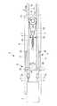
本実施形態に係る処置具駆動装置1は、図1および図2に示されるように、処置具3を着脱可能に取り付ける中間機構部4と、該中間機構部4に着脱可能に取り付けられる駆動部5とを備えている。
処置具3の2本一対のワイヤ2の端部には球体2aが固定されている。As shown in FIG. 1 and FIG. 2, the treatment instrument drive device 1 according to the present embodiment includes an intermediate mechanism section 4 that detachably attaches the
A
中間機構部4は、ベース6と、該ベース6の表面に、相互に平行に配置されて、長手方向に移動可能に支持された2本のラックギヤ7と、該ラックギヤ7の端部を揃えて配置する整列機構8と、該ラックギヤ7にそれぞれ噛み合う2つのピニオンギヤ9と、該ピニオンギヤ9を一方向に回転させるように付勢する付勢手段10とを備えている。ラックギヤ7を支持する機構については図示を省略している。 The intermediate mechanism portion 4 has a
2本のラックギヤ7は、図1に示されるように、平面視では、それらの歯7aを相互に対向させて配置されており、図2に示されるように、側面視では厚さ方向に異なる位置に配置されている。 As shown in FIG. 1, the two
各ラックギヤ7の端部には、図5(a)に示されるように、2本爪のフック11が取り付けられている。フック11の2本の爪11aはワイヤ2の直径より大きく球体2aの外径より小さい間隔をあけて配置されている。これにより、図5(b)に示されるように、爪11aの間にワイヤ2を貫通させて、爪11aに球体2aを引っ掛けることにより、ワイヤ2の端部をラックギヤ7に取り付けることができるようになっている。 As shown in FIG. 5A, a two-
なお、フック11は図5のように容易に外れる構成を採用してもよいし、図6に示されるように、2本爪への球体2aの入口が狭く、2本爪がバネ性を有して、球体2aをフック11に引っ掛けるときには球体2aによって2本爪を弾性変形させて入口を押し広げて引っ掛けてもよい。このようにすることで、ワイヤが弛んだだけではフック11から球体2aが外れないようにすることができる。 The
2つのピニオンギヤ(動力伝達機構)9は、図2、図7および図8に示されるように、同軸に配置され、かつ、ベアリング12によって相対回転自在にベース6に支持されている。各ピニオンギヤ9は異なるラックギヤ7に噛み合うように配置されている。図中、符号13はスペーサである。 As shown in FIGS. 2, 7, and 8, the two pinion gears (power transmission mechanisms) 9 are arranged coaxially and supported by the
ピニオンギヤ9には、中央に貫通孔が形成され、該貫通孔の内面には長手方向に沿うスプライン溝が周方向に複数形成されて、スプライン孔(嵌合孔)14が構成されている。2つのピニオンギヤ9のスプライン孔14は同一の形状を有している。
各ピニオンギヤ9の軸方向の一部には、後述する付勢手段10のワイヤ15を巻き付けるプーリ部16が設けられている。The
A
整列機構8は、ベース6に、ラックギヤ7と平行に設けられたガイドレール17と、該ガイドレール17上に直線移動可能に支持されたスライダ18と、スライダ18に設けられた突当部材19とを備えている。スライダ18には、ベース6の幅方向の一方に突出し操作者によって操作される操作レバー20が設けられている。 The
突当部材19は、各ラックギヤ7の端部の段差21に突き当たる位置に配置されている。スライダ18の移動によって段差21に突き当てることにより、ラックギヤ7の端部を揃えるようになっている。
スライダ18は、図4に示されるように、係合突起(係止機構)18aを備えていて、ラックギヤ7を最もフック11側に移動させた位置で、係合突起18aを可動フック(係止機構)22に引っ掛けることによりその位置に静止状態に維持されるようになっている。The abutting
As shown in FIG. 4, the
付勢手段10は、2つのピニオンギヤ9に設けられたプーリ部16に巻かれるワイヤ(ワイヤ状部材)15と、該ワイヤ15の長さ方向の途中位置を牽引するための可動プーリ(プーリ状部材)23と、該可動プーリ23に一端が固定され、該可動プーリ23をワイヤ15に張力を付与する方向(図中矢印Aの方向)に付勢するスプリング(付勢部材)24とを備えている。スプリング24の他端はベース6に固定されている。 The urging means 10 includes a wire (wire-like member) 15 wound around a
ワイヤ15の一端は一方のピニオンギヤ9のプーリ部16に巻き付けられてから固定され、ワイヤ15の他端は他方のピニオンギヤ9のプーリ部16に巻き付けられてから固定されている。ワイヤ15の巻き付け方向は、各ピニオンギヤ9に噛み合っているラックギヤ7がフック11の設けられている端部とは反対側の端部の方向(矢印Bの方向)に移動することとなるように巻かれている。 One end of the
すなわち、時計回りにワイヤ15が巻き付けられたプーリ部16は、ワイヤ15に張力が付与されると反時計回りの回転力を受けるので、ピニオンギヤ9を反時計回りに回転させ、これに噛み合うラックギヤ7を矢印Bの方向に移動させるようになっている。また、反時計回りにワイヤ15が巻き付けられたプーリ部16は、ピニオンギヤ9を時計回りに回転させ、これに噛み合うラックギヤ7を矢印Bの方向に移動させるようになっている。 That is, the
駆動部5は、モータ25と、該モータ25によって回転させられるスプライン軸(嵌合軸)26とを備えている。また、駆動部5は、図示しない挿脱機構によってスプライン軸26を長手方向に移動させることができ、図7に示されるように、ピニオンギヤ9のスプライン孔14からスプライン軸26を抜き出した状態と、図8に示されるように、スプライン孔14にスプライン軸26を挿入した状態とを切り替えることができるようになっている。 The
処置具3は、該処置具3を中間機構部4に取り付けるために、ワイヤ2を一時的に支持するワイヤ支持部27に取り付けられた状態で、中間機構部4に取り付けられるようになっている。ワイヤ支持部27は、図3および図4に示されるように、処置具3に着脱可能に取り付けられるフレーム27aと、該フレーム27aに揺動可能に取り付けられるアーム27bとを備えている。これらの図においては、簡単のために処置具3の一対のワイヤ2の内、一方のワイヤ2のみを示しているが、他のワイヤ2についても同じ方法で支持されている。整列機構8とワイヤ支持部27とによって、ワイヤ支持部27によるワイヤ2の支持状態をフック11との連結状態に切り替える切替機構が構成されている。 In order to attach the
アーム27bの先端には、ワイヤ2の外径より大きく球体2aの直径より小さい幅のスリット27cと、球体2aを安定的に接触させる窪み27dとが備えられている。アーム27bを図3に示すように配置した状態で、スリット27cにワイヤ2を通して球体2aを窪み27dに配置して、ワイヤ2を弛みなく延ばした状態に保持するようになっている。 At the tip of the
アーム27bはフレーム27aに対して一方向に揺動可能に設けられており、フレーム27aの先端には、アーム27bが揺動することによりアーム27bの先端に支持されている球体2aが移動すると、その球体2aに突き当たって球体2aの移動を阻止し、窪み27dから離脱させるストッパ27eが設けられている。符号27f,27gは、フレーム27aを処置具3に着脱するための突起と溝である。 The
また、処置具3は、ベース6に対してベース6の表面に直交する方向に移動させながら取り付けられるようになっており、その移動時に、可動フック22を押して、該可動フック22とスライダ18の係止突起18aとの係合状態を解除するようになっている。
また、ベース6には、図4に示されるように、処置具3を取り付ける際のベース6の表面に直交する方向への動作によってアーム27bを揺動させるための突当部材6aが備えられている。The
Further, as shown in FIG. 4, the
このように構成された本実施形態に係る処置具駆動装置1の作用について以下に説明する。
本実施形態に係る処置具駆動装置1に処置具3を取り付けるには、駆動部5が切り離された状態の中間機構部4の操作レバー20を操作してスライダ18を移動させる。これにより、スライダ18に設けられた突当部材19が段差21に突き当たって2つのラックギヤ7を整列させつつフック11側に向かって移動させる。The operation of the treatment instrument driving apparatus 1 according to the present embodiment configured as described above will be described below.
In order to attach the
ラックギヤ7にはピニオンギヤ9が噛み合っており、ピニオンギヤ9は付勢手段10に接続されているので、ラックギヤ7が移動するとピニオンギヤ9がプーリ部16にワイヤ15を巻き取る方向に回転して可動プーリ23を移動させ、それによってスプリング24が伸びて付勢力が増加していく。操作者は、この付勢力に抗して操作レバー20を移動させることにより、2つのラックギヤ7の端部のフック11の位置が揃えられる。また、ラックギヤ7が最もフック11側に移動した位置で、図4(a)に示されるように、スライダ18に設けられた係合突起18aがベース6に設けられた可動フック22に引っかかることによりスライダ18がその位置に係止される。 Since the
また、図3に示されるように、処置具3にワイヤ支持部27を取り付けておく。すなわち、処置具3にフレーム27aを取り付け、アーム27bの先端のスリット27cをワイヤ2が通過するようにして、ワイヤ2の先端の球体2aをアーム27bの先端の窪み27dに収容する。これにより、図3に示されるように、ワイヤ2が弛みなく延びた状態に維持される。 Further, as shown in FIG. 3, the
このようにして準備された処置具3を図4に示されるように中間機構部4に取り付ける。すなわち、ワイヤ支持部27によってワイヤ2が弛みなく支持された処置具3をフックが揃えられた中間機構部4に対して近接させ、図4(a)に示されるように、球体2aをフック11に引っかかる位置に配置する。この時点で、ベース6に設けられた突当部材6aがアーム27bに突き当たる。 The
そして、図4(b)の矢印Cに示されるように、処置具3を中間機構部4にさらに近接させていくと、突当部材6aによってアーム27bが揺動させられる。アーム27bに支持された球体2aも一緒に揺動しようとするが、フレーム27aに設けられたストッパ27eが球体2aに突き当たるので、アーム27bの窪みから球体2aが離脱して、フック11内に放出される。これと同時に、処置具3が可動フック22を押すことにより、可動フック22が矢印Dに示されるように揺動して、係合突起18aとの係合が解除される。 Then, as shown by an arrow C in FIG. 4B, when the
これにより、図4(c)に矢印Eで示されるように、付勢手段10の付勢力によって、ラックギヤ7がフック11を牽引する方向に移動させられるので、フック11に球体2aを係合させたワイヤ2に、付勢力に応じた初期張力が付与される。このとき、2つのラックギヤ7にそれぞれ噛み合う2つのピニオンギヤ9はそれぞれのプーリ部16に巻かれたワイヤ15を巻き出す方向に回転させられるが、ワイヤ15は可動プーリ23を介して連続しているので、張力をバランスさせるように可動プーリ23が回転し、処置具3のワイヤ2と付勢手段10のワイヤ15の張力が釣り合う位置で停止する。このとき、スライダ18は図示しないバネによってストッパ33の位置まで移動し、突当突起19と段差21との係合が外れる。 As a result, as indicated by an arrow E in FIG. 4C, the
この状態で、処置具3からフレーム27aを取り外すとともに、図7および図8に示されるように、2つのピニオンギヤ9に形成されているスプライン孔14に駆動部5のスプライン軸26を挿入して噛み合わせる。これにより、2つのピニオンギヤ9が連結されるとともに、モータ25の駆動力が2つのピニオンギヤ9に伝達されるようになる。したがって、モータ25の駆動により、2つのピニオンギヤ9は同一方向に回転し、該ピニオンギヤ9を挟んで平行に配置されているラックギヤ7は互いに逆方向に移動するようになる。 In this state, the
すなわち、一方のラックギヤ7に接続している処置具3のワイヤ2には張力が付与され、他方のラックギヤ7に接続しているワイヤ2の張力は緩められる。その結果、モータ25の駆動によって、処置具3の一対のワイヤ2に、択一的に張力を付与することができる。これにより、処置具3の関節等を駆動することができる。 That is, tension is applied to the
この場合において、本実施形態に係る処置具駆動装置1によれば、付勢手段10のワイヤ15は可動プーリ23に回し掛けられているので、モータ25の駆動によるピニオンギヤ9の回転時には、一方のピニオンギヤ9のプーリ部16に巻き取られるワイヤ15は他方のピニオンギヤ9のプーリ部16に同じ長さだけ巻き取られる。したがって、スプライン軸のスプライン孔への挿入後は、可動プーリ23の位置が変動することはなく、したがって、ラックギヤ7の移動に対して付勢手段10が切り離された状態とすることができる。 In this case, according to the treatment instrument driving apparatus 1 according to the present embodiment, since the
本実施形態に係る処置具駆動装置1によれば、処置具3を中間機構部4に取り付ける際に、処置具3の一対のワイヤ2に初期張力が自動的に付与されるので、処置具3の複数のワイヤ2の張力を個別に調節する必要がなく、調節に要する手間を省くことができるという利点がある。本実施形態では2本一対のワイヤ2を例に挙げて説明したが、処置具3が複数対のワイヤ2を備える場合においても同様に全てのワイヤ2に同時に初期張力を付与することができ、さらに大幅に手間を削減することができる。 According to the treatment instrument driving apparatus 1 according to the present embodiment, when the
また、ラックギヤ7に設けたフック11にワイヤ2の球体2aを引っ掛けているだけなので、処置具駆動装置1から処置具3を取り外す際にも、フック11から球体2aを取り外して簡単に取り外すことができるという利点がある。 Further, since the
なお、本実施形態においては、処置具3が一対のワイヤ2によって駆動される場合について説明したが、張力伝達部材としてはワイヤ2に限定されるものではなく、ベルトやチューブ、あるいは、張力のみならず押圧力も伝達可能な部材を採用してもよい。
また、処置具3が複数の関節等を有し、複数対のワイヤ2によって駆動される場合には、関節毎に初期張力を異ならせるように調節されるようにしてもよい。In the present embodiment, the case where the
Further, when the
また、ワイヤ15を巻き付ける可動プーリ23あるいはプーリ部16は回転しない円筒面を有する柱状体であってもよい。ワイヤ15を円筒面に沿って滑らせることとすれば同様の効果を得ることができる。 Further, the
また、ワイヤ2とラックギヤ7とを連結する構造として球体2aとフック11とを例示したが、これに代えて、任意の接続構造を採用してもよい。
また、本実施形態においては、処置具3のワイヤ2に連結される中間機構部4の可動部材としてラックギヤ7を採用したが、これに代えて、図9に示されるように、プーリ28に巻かれるワイヤ29を採用してもよい。この場合には、駆動力伝達機構としては、プーリ28に固定された従動平歯車30と、モータ25により回転させられる駆動平歯車31とを備えるものを採用すればよい。Moreover, although the
In the present embodiment, the
このように構成すると、駆動平歯車31が従動平歯車30に噛み合っていない状態では、2つの従動平歯車30およびそれらに固定されたプーリ28は回転自在となって、付勢手段10の付勢力にしたがってワイヤ29の張力をバランスさせる位置まで自由に回転することができる。そして、張力がバランスした状態で、駆動平歯車31を2つの従動平歯車30の間に挿入して噛み合わせることにより、付勢手段10の付勢力の影響を切り離して、2つのワイヤ29に択一的に張力を付与することができるようになる。 With this configuration, in the state where the
また、付勢手段10として、ピニオンギヤ9に設けられたプーリ部16に回転力を作用させることとしたが、図10に示されるように、ラックギヤ7に直接張力を作用させるものを採用してもよい。符号32は固定プーリである。また、図10のピニオンギヤ9をなくして、駆動部5のスプライン軸26に代えてピニオンギヤを採用し、ラックギヤ7間に直接挿脱することにしてもよい。 Further, as the urging means 10, a rotational force is applied to the
1 処置具駆動装置
2 ワイヤ(張力伝達部材)
3 処置具
4 中間機構部
7 ラックギヤ(可動部材)
8 整列機構
9 ピニオンギヤ(動力伝達機構)
10 付勢手段
14 スプライン孔(嵌合孔)
15 ワイヤ(ワイヤ状部材)
18 スライダ
18a 係合突起(係止機構)
22 可動フック(係止機構)
23 可動プーリ(プーリ状部材)
24 スプリング(付勢部材)
25 モータ(駆動源)
26 スプライン軸(嵌合軸)
27 ワイヤ支持部(処置具側支持部)
29 ワイヤ(可動部材)
30 従動平歯車(従動歯車)
31 駆動平歯車(駆動歯車)1 treatment
3 treatment tool 4
8
10 Biasing means 14 Spline hole (fitting hole)
15 wire (wire-like member)
18
22 Movable hook (locking mechanism)
23 Movable pulley (pulley-like member)
24 Spring (biasing member)
25 Motor (drive source)
26 Spline shaft (fitting shaft)
27 Wire support part (treatment tool side support part)
29 Wire (movable member)
30 driven spur gear (driven gear)
31 Drive Spur Gear (Drive Gear)
Claims (9)
Translated fromJapanese各前記張力伝達部材の一端にそれぞれ着脱可能に取り付けられる可動部材と、
前記処置具を駆動する動力を発生する駆動源と、
該駆動源と前記可動部材との連結または連結解除を切り替えるとともに、連結された状態で、対となる前記張力伝達部材に択一的に張力を加えるように、前記対となる前記張力伝達部材に取り付けられた2つの前記可動部材に前記駆動源からの動力を伝達する動力伝達機構と、
該動力伝達機構による連結が解除された状態で、2つの前記可動部材を前記張力伝達部材に張力が付与される方向に付勢する付勢手段とを備える処置具駆動装置。A treatment instrument driving device that is detachably attached to a treatment instrument that includes at least a pair of tension transmission members, and that drives the treatment instrument by tension applied to the tension transmission member,
A movable member detachably attached to one end of each tension transmission member;
A drive source for generating power for driving the treatment instrument;
It switches the uncoupling of the movable member and said drive source, a connecting state, Oneto-option in the tension transmission member forming a pair to applytension to the tension transmission member forming the pair A power transmission mechanism for transmitting power from the drive source to thetwo movable members attached ;
A treatment instrument driving device comprising: an urging unit that urges the two movable members in a direction in which a tension is applied to the tension transmission member in a state where the connection by the power transmission mechanism is released.
該中間機構部が、前記可動部材と、前記動力伝達機構と、前記付勢手段とを備え、
前記動力伝達機構が、前記中間機構部に前記駆動源を着脱することにより、該駆動源と前記可動部材との連結または連結解除を切り替える請求項1に記載の処置具駆動装置。An intermediate mechanism part detachably coupled to the treatment instrument;
The intermediate mechanism portion includes the movable member, the power transmission mechanism, and the biasing means.
The treatment tool drive device according to claim 1, wherein the power transmission mechanism switches connection or disconnection between the drive source and the movable member by attaching and detaching the drive source to and from the intermediate mechanism portion.
2つの前記可動部材が、それぞれ長手方向に移動可能に略平行にかつ歯を対向させて支持された2つのラックギヤであり、
前記動力伝達機構が、2つの前記ラックギヤにそれぞれ噛み合い、前記モータの駆動によって2つの前記ラックギヤを逆方向に移動させるピニオンギヤを備える請求項2に記載の処置具駆動装置。The drive source is a motor;
The two movable members are two rack gears supported so as to be movable substantially parallel to each other in the longitudinal direction and facing teeth;
The treatment tool drive device according to claim 2, wherein the power transmission mechanism includes a pinion gear that meshes with each of the two rack gears and moves the two rack gears in opposite directions by driving of the motor.
前記動力伝達機構が、各前記ピニオンギヤに設けられた嵌合孔と、前記モータに固定され、2つの前記ピニオンギヤに設けられた前記嵌合孔に嵌合して2つの前記ピニオンギヤを連結する嵌合軸とを備える請求項3に記載の処置具駆動装置。The pinion gear is individually provided for the two rack gears, and is arranged so as to be rotatable coaxially with each other.
The power transmission mechanism is fitted to the fitting hole provided in each of the pinion gears and the fitting hole fixed to the motor and fitted into the fitting holes provided in the two pinion gears to connect the two pinion gears. The treatment instrument drive device according to claim 3, comprising a shaft.
2つの前記可動部材がワイヤ状部材であり、
前記動力伝達機構が、2つの前記ワイヤ状部材をそれぞれ巻回する2つのプーリ状部材と、各該プーリ状部材に同軸に固定された従動歯車と、各該従動歯車に同時に噛み合う位置に挿脱可能に設けられ、噛み合った状態で前記モータの駆動によって2つの前記ワイヤ状部材を逆方向に移動させる駆動歯車とを備える請求項2に記載の処置具駆動装置。The drive source is a motor;
The two movable members are wire-like members;
The power transmission mechanism is inserted into and removed from two pulley-like members wound around the two wire-like members, a driven gear coaxially fixed to each pulley-like member, and a position simultaneously meshed with each driven gear. The treatment instrument drive device according to claim 2, further comprising a drive gear that is provided so as to move the two wire-like members in opposite directions by driving the motor in a meshed state.
前記中間機構部に、複数の前記可動部材を前記張力伝達部材との連結位置に整列状態に保持する整列機構が設けられ、
前記中間機構部への前記処置具の取付時に、前記処置具側支持部による前記張力伝達部材の保持状態を解除して、該張力伝達部材の一端を前記整列機構により整列された前記可動部材に連結する切替機構を備える請求項2から請求項6のいずれかに記載の処置具駆動装置。A treatment instrument-side support section that is detachably attached to the treatment instrument and holds the plurality of tension transmission members in a positioning state;
The intermediate mechanism is provided with an alignment mechanism that holds the plurality of movable members in alignment with the connection positions with the tension transmission member,
When the treatment instrument is attached to the intermediate mechanism, the tension transmission member is held by the treatment instrument side support, and one end of the tension transmission member is moved to the movable member aligned by the alignment mechanism. The treatment instrument drive device according to any one of claims2 to 6, further comprising a switching mechanism to be connected.
前記可動部材が連結位置に配置されるように前記スライダを係止する係止機構とを備え、
前記切替機構は、前記張力伝達部材が前記可動部材に連結された状態で前記係止機構による前記スライダの係止状態を解除する請求項7に記載の処置具駆動装置。A slider for moving the plurality of movable members against an urging force by the urging means;
A locking mechanism that locks the slider so that the movable member is disposed at a coupling position;
The treatment tool driving apparatus according to claim 7, wherein the switching mechanism releases the locked state of the slider by the locking mechanism in a state where the tension transmission member is connected to the movable member.
Priority Applications (5)
| Application Number | Priority Date | Filing Date | Title |
|---|---|---|---|
| JP2014152518AJP6265859B2 (en) | 2014-07-28 | 2014-07-28 | Treatment instrument drive |
| PCT/JP2015/071288WO2016017597A1 (en) | 2014-07-28 | 2015-07-27 | Treatment-tool driving device |
| EP15828121.2AEP3175812B1 (en) | 2014-07-28 | 2015-07-27 | Treatment-tool driving device |
| CN201580040308.1ACN106535737B (en) | 2014-07-28 | 2015-07-27 | Disposal appliance drive |
| US15/413,720US10085728B2 (en) | 2014-07-28 | 2017-01-24 | Treatment-tool driving device |
Applications Claiming Priority (1)
| Application Number | Priority Date | Filing Date | Title |
|---|---|---|---|
| JP2014152518AJP6265859B2 (en) | 2014-07-28 | 2014-07-28 | Treatment instrument drive |
Publications (2)
| Publication Number | Publication Date |
|---|---|
| JP2016029994A JP2016029994A (en) | 2016-03-07 |
| JP6265859B2true JP6265859B2 (en) | 2018-01-24 |
Family
ID=55217497
Family Applications (1)
| Application Number | Title | Priority Date | Filing Date |
|---|---|---|---|
| JP2014152518AActiveJP6265859B2 (en) | 2014-07-28 | 2014-07-28 | Treatment instrument drive |
Country Status (5)
| Country | Link |
|---|---|
| US (1) | US10085728B2 (en) |
| EP (1) | EP3175812B1 (en) |
| JP (1) | JP6265859B2 (en) |
| CN (1) | CN106535737B (en) |
| WO (1) | WO2016017597A1 (en) |
Families Citing this family (411)
| Publication number | Priority date | Publication date | Assignee | Title |
|---|---|---|---|---|
| US20070084897A1 (en) | 2003-05-20 | 2007-04-19 | Shelton Frederick E Iv | Articulating surgical stapling instrument incorporating a two-piece e-beam firing mechanism |
| US9060770B2 (en) | 2003-05-20 | 2015-06-23 | Ethicon Endo-Surgery, Inc. | Robotically-driven surgical instrument with E-beam driver |
| US11890012B2 (en) | 2004-07-28 | 2024-02-06 | Cilag Gmbh International | Staple cartridge comprising cartridge body and attached support |
| US11998198B2 (en) | 2004-07-28 | 2024-06-04 | Cilag Gmbh International | Surgical stapling instrument incorporating a two-piece E-beam firing mechanism |
| US9072535B2 (en) | 2011-05-27 | 2015-07-07 | Ethicon Endo-Surgery, Inc. | Surgical stapling instruments with rotatable staple deployment arrangements |
| US8215531B2 (en) | 2004-07-28 | 2012-07-10 | Ethicon Endo-Surgery, Inc. | Surgical stapling instrument having a medical substance dispenser |
| US9237891B2 (en) | 2005-08-31 | 2016-01-19 | Ethicon Endo-Surgery, Inc. | Robotically-controlled surgical stapling devices that produce formed staples having different lengths |
| US7669746B2 (en) | 2005-08-31 | 2010-03-02 | Ethicon Endo-Surgery, Inc. | Staple cartridges for forming staples having differing formed staple heights |
| US7934630B2 (en) | 2005-08-31 | 2011-05-03 | Ethicon Endo-Surgery, Inc. | Staple cartridges for forming staples having differing formed staple heights |
| US11246590B2 (en) | 2005-08-31 | 2022-02-15 | Cilag Gmbh International | Staple cartridge including staple drivers having different unfired heights |
| US10159482B2 (en) | 2005-08-31 | 2018-12-25 | Ethicon Llc | Fastener cartridge assembly comprising a fixed anvil and different staple heights |
| US11484312B2 (en) | 2005-08-31 | 2022-11-01 | Cilag Gmbh International | Staple cartridge comprising a staple driver arrangement |
| US20070106317A1 (en) | 2005-11-09 | 2007-05-10 | Shelton Frederick E Iv | Hydraulically and electrically actuated articulation joints for surgical instruments |
| US11278279B2 (en) | 2006-01-31 | 2022-03-22 | Cilag Gmbh International | Surgical instrument assembly |
| US20110024477A1 (en) | 2009-02-06 | 2011-02-03 | Hall Steven G | Driven Surgical Stapler Improvements |
| US20110295295A1 (en) | 2006-01-31 | 2011-12-01 | Ethicon Endo-Surgery, Inc. | Robotically-controlled surgical instrument having recording capabilities |
| US7753904B2 (en) | 2006-01-31 | 2010-07-13 | Ethicon Endo-Surgery, Inc. | Endoscopic surgical instrument with a handle that can articulate with respect to the shaft |
| US11793518B2 (en) | 2006-01-31 | 2023-10-24 | Cilag Gmbh International | Powered surgical instruments with firing system lockout arrangements |
| US8820603B2 (en) | 2006-01-31 | 2014-09-02 | Ethicon Endo-Surgery, Inc. | Accessing data stored in a memory of a surgical instrument |
| US8186555B2 (en) | 2006-01-31 | 2012-05-29 | Ethicon Endo-Surgery, Inc. | Motor-driven surgical cutting and fastening instrument with mechanical closure system |
| US8708213B2 (en) | 2006-01-31 | 2014-04-29 | Ethicon Endo-Surgery, Inc. | Surgical instrument having a feedback system |
| US20120292367A1 (en) | 2006-01-31 | 2012-11-22 | Ethicon Endo-Surgery, Inc. | Robotically-controlled end effector |
| US7845537B2 (en) | 2006-01-31 | 2010-12-07 | Ethicon Endo-Surgery, Inc. | Surgical instrument having recording capabilities |
| US11224427B2 (en) | 2006-01-31 | 2022-01-18 | Cilag Gmbh International | Surgical stapling system including a console and retraction assembly |
| US8992422B2 (en) | 2006-03-23 | 2015-03-31 | Ethicon Endo-Surgery, Inc. | Robotically-controlled endoscopic accessory channel |
| US8322455B2 (en) | 2006-06-27 | 2012-12-04 | Ethicon Endo-Surgery, Inc. | Manually driven surgical cutting and fastening instrument |
| US10568652B2 (en) | 2006-09-29 | 2020-02-25 | Ethicon Llc | Surgical staples having attached drivers of different heights and stapling instruments for deploying the same |
| US7506791B2 (en) | 2006-09-29 | 2009-03-24 | Ethicon Endo-Surgery, Inc. | Surgical stapling instrument with mechanical mechanism for limiting maximum tissue compression |
| US11980366B2 (en) | 2006-10-03 | 2024-05-14 | Cilag Gmbh International | Surgical instrument |
| US8684253B2 (en) | 2007-01-10 | 2014-04-01 | Ethicon Endo-Surgery, Inc. | Surgical instrument with wireless communication between a control unit of a robotic system and remote sensor |
| US11291441B2 (en) | 2007-01-10 | 2022-04-05 | Cilag Gmbh International | Surgical instrument with wireless communication between control unit and remote sensor |
| US8652120B2 (en) | 2007-01-10 | 2014-02-18 | Ethicon Endo-Surgery, Inc. | Surgical instrument with wireless communication between control unit and sensor transponders |
| US8632535B2 (en) | 2007-01-10 | 2014-01-21 | Ethicon Endo-Surgery, Inc. | Interlock and surgical instrument including same |
| US11039836B2 (en) | 2007-01-11 | 2021-06-22 | Cilag Gmbh International | Staple cartridge for use with a surgical stapling instrument |
| US20080169333A1 (en) | 2007-01-11 | 2008-07-17 | Shelton Frederick E | Surgical stapler end effector with tapered distal end |
| US7673782B2 (en) | 2007-03-15 | 2010-03-09 | Ethicon Endo-Surgery, Inc. | Surgical stapling instrument having a releasable buttress material |
| US11564682B2 (en) | 2007-06-04 | 2023-01-31 | Cilag Gmbh International | Surgical stapler device |
| US8931682B2 (en) | 2007-06-04 | 2015-01-13 | Ethicon Endo-Surgery, Inc. | Robotically-controlled shaft based rotary drive systems for surgical instruments |
| US7753245B2 (en) | 2007-06-22 | 2010-07-13 | Ethicon Endo-Surgery, Inc. | Surgical stapling instruments |
| US11849941B2 (en) | 2007-06-29 | 2023-12-26 | Cilag Gmbh International | Staple cartridge having staple cavities extending at a transverse angle relative to a longitudinal cartridge axis |
| US8636736B2 (en) | 2008-02-14 | 2014-01-28 | Ethicon Endo-Surgery, Inc. | Motorized surgical cutting and fastening instrument |
| US11986183B2 (en) | 2008-02-14 | 2024-05-21 | Cilag Gmbh International | Surgical cutting and fastening instrument comprising a plurality of sensors to measure an electrical parameter |
| US8758391B2 (en) | 2008-02-14 | 2014-06-24 | Ethicon Endo-Surgery, Inc. | Interchangeable tools for surgical instruments |
| US7819298B2 (en) | 2008-02-14 | 2010-10-26 | Ethicon Endo-Surgery, Inc. | Surgical stapling apparatus with control features operable with one hand |
| US9179912B2 (en) | 2008-02-14 | 2015-11-10 | Ethicon Endo-Surgery, Inc. | Robotically-controlled motorized surgical cutting and fastening instrument |
| US8573465B2 (en) | 2008-02-14 | 2013-11-05 | Ethicon Endo-Surgery, Inc. | Robotically-controlled surgical end effector system with rotary actuated closure systems |
| US7866527B2 (en) | 2008-02-14 | 2011-01-11 | Ethicon Endo-Surgery, Inc. | Surgical stapling apparatus with interlockable firing system |
| JP5410110B2 (en) | 2008-02-14 | 2014-02-05 | エシコン・エンド−サージェリィ・インコーポレイテッド | Surgical cutting / fixing instrument with RF electrode |
| US9585657B2 (en) | 2008-02-15 | 2017-03-07 | Ethicon Endo-Surgery, Llc | Actuator for releasing a layer of material from a surgical end effector |
| US9005230B2 (en) | 2008-09-23 | 2015-04-14 | Ethicon Endo-Surgery, Inc. | Motorized surgical instrument |
| US8210411B2 (en) | 2008-09-23 | 2012-07-03 | Ethicon Endo-Surgery, Inc. | Motor-driven surgical cutting instrument |
| US11648005B2 (en) | 2008-09-23 | 2023-05-16 | Cilag Gmbh International | Robotically-controlled motorized surgical instrument with an end effector |
| US9386983B2 (en) | 2008-09-23 | 2016-07-12 | Ethicon Endo-Surgery, Llc | Robotically-controlled motorized surgical instrument |
| US8608045B2 (en) | 2008-10-10 | 2013-12-17 | Ethicon Endo-Sugery, Inc. | Powered surgical cutting and stapling apparatus with manually retractable firing system |
| US8517239B2 (en) | 2009-02-05 | 2013-08-27 | Ethicon Endo-Surgery, Inc. | Surgical stapling instrument comprising a magnetic element driver |
| RU2525225C2 (en) | 2009-02-06 | 2014-08-10 | Этикон Эндо-Серджери, Инк. | Improvement of drive surgical suturing instrument |
| US8444036B2 (en) | 2009-02-06 | 2013-05-21 | Ethicon Endo-Surgery, Inc. | Motor driven surgical fastener device with mechanisms for adjusting a tissue gap within the end effector |
| US8220688B2 (en) | 2009-12-24 | 2012-07-17 | Ethicon Endo-Surgery, Inc. | Motor-driven surgical cutting instrument with electric actuator directional control assembly |
| US8851354B2 (en) | 2009-12-24 | 2014-10-07 | Ethicon Endo-Surgery, Inc. | Surgical cutting instrument that analyzes tissue thickness |
| US8783543B2 (en) | 2010-07-30 | 2014-07-22 | Ethicon Endo-Surgery, Inc. | Tissue acquisition arrangements and methods for surgical stapling devices |
| US9629814B2 (en) | 2010-09-30 | 2017-04-25 | Ethicon Endo-Surgery, Llc | Tissue thickness compensator configured to redistribute compressive forces |
| US9788834B2 (en) | 2010-09-30 | 2017-10-17 | Ethicon Llc | Layer comprising deployable attachment members |
| US11298125B2 (en) | 2010-09-30 | 2022-04-12 | Cilag Gmbh International | Tissue stapler having a thickness compensator |
| US12213666B2 (en) | 2010-09-30 | 2025-02-04 | Cilag Gmbh International | Tissue thickness compensator comprising layers |
| US9386988B2 (en) | 2010-09-30 | 2016-07-12 | Ethicon End-Surgery, LLC | Retainer assembly including a tissue thickness compensator |
| US10945731B2 (en) | 2010-09-30 | 2021-03-16 | Ethicon Llc | Tissue thickness compensator comprising controlled release and expansion |
| US11925354B2 (en) | 2010-09-30 | 2024-03-12 | Cilag Gmbh International | Staple cartridge comprising staples positioned within a compressible portion thereof |
| US9351730B2 (en) | 2011-04-29 | 2016-05-31 | Ethicon Endo-Surgery, Llc | Tissue thickness compensator comprising channels |
| US9016542B2 (en) | 2010-09-30 | 2015-04-28 | Ethicon Endo-Surgery, Inc. | Staple cartridge comprising compressible distortion resistant components |
| US11812965B2 (en) | 2010-09-30 | 2023-11-14 | Cilag Gmbh International | Layer of material for a surgical end effector |
| US8695866B2 (en) | 2010-10-01 | 2014-04-15 | Ethicon Endo-Surgery, Inc. | Surgical instrument having a power control circuit |
| AU2012250197B2 (en) | 2011-04-29 | 2017-08-10 | Ethicon Endo-Surgery, Inc. | Staple cartridge comprising staples positioned within a compressible portion thereof |
| US11207064B2 (en) | 2011-05-27 | 2021-12-28 | Cilag Gmbh International | Automated end effector component reloading system for use with a robotic system |
| US9044230B2 (en) | 2012-02-13 | 2015-06-02 | Ethicon Endo-Surgery, Inc. | Surgical cutting and fastening instrument with apparatus for determining cartridge and firing motion status |
| MX358135B (en) | 2012-03-28 | 2018-08-06 | Ethicon Endo Surgery Inc | Tissue thickness compensator comprising a plurality of layers. |
| JP6224070B2 (en) | 2012-03-28 | 2017-11-01 | エシコン・エンド−サージェリィ・インコーポレイテッドEthicon Endo−Surgery,Inc. | Retainer assembly including tissue thickness compensator |
| BR112014024098B1 (en) | 2012-03-28 | 2021-05-25 | Ethicon Endo-Surgery, Inc. | staple cartridge |
| US9101358B2 (en) | 2012-06-15 | 2015-08-11 | Ethicon Endo-Surgery, Inc. | Articulatable surgical instrument comprising a firing drive |
| US9289256B2 (en) | 2012-06-28 | 2016-03-22 | Ethicon Endo-Surgery, Llc | Surgical end effectors having angled tissue-contacting surfaces |
| US20140005718A1 (en) | 2012-06-28 | 2014-01-02 | Ethicon Endo-Surgery, Inc. | Multi-functional powered surgical device with external dissection features |
| US9282974B2 (en) | 2012-06-28 | 2016-03-15 | Ethicon Endo-Surgery, Llc | Empty clip cartridge lockout |
| US11278284B2 (en) | 2012-06-28 | 2022-03-22 | Cilag Gmbh International | Rotary drive arrangements for surgical instruments |
| BR112014032776B1 (en) | 2012-06-28 | 2021-09-08 | Ethicon Endo-Surgery, Inc | SURGICAL INSTRUMENT SYSTEM AND SURGICAL KIT FOR USE WITH A SURGICAL INSTRUMENT SYSTEM |
| US20140001231A1 (en) | 2012-06-28 | 2014-01-02 | Ethicon Endo-Surgery, Inc. | Firing system lockout arrangements for surgical instruments |
| JP6290201B2 (en) | 2012-06-28 | 2018-03-07 | エシコン・エンド−サージェリィ・インコーポレイテッドEthicon Endo−Surgery,Inc. | Lockout for empty clip cartridge |
| US9408606B2 (en) | 2012-06-28 | 2016-08-09 | Ethicon Endo-Surgery, Llc | Robotically powered surgical device with manually-actuatable reversing system |
| US12383267B2 (en) | 2012-06-28 | 2025-08-12 | Cilag Gmbh International | Robotically powered surgical device with manually-actuatable reversing system |
| RU2672520C2 (en) | 2013-03-01 | 2018-11-15 | Этикон Эндо-Серджери, Инк. | Hingedly turnable surgical instruments with conducting ways for signal transfer |
| BR112015021082B1 (en) | 2013-03-01 | 2022-05-10 | Ethicon Endo-Surgery, Inc | surgical instrument |
| US9808244B2 (en) | 2013-03-14 | 2017-11-07 | Ethicon Llc | Sensor arrangements for absolute positioning system for surgical instruments |
| US9629629B2 (en) | 2013-03-14 | 2017-04-25 | Ethicon Endo-Surgey, LLC | Control systems for surgical instruments |
| BR112015026109B1 (en) | 2013-04-16 | 2022-02-22 | Ethicon Endo-Surgery, Inc | surgical instrument |
| US9826976B2 (en) | 2013-04-16 | 2017-11-28 | Ethicon Llc | Motor driven surgical instruments with lockable dual drive shafts |
| MX369362B (en) | 2013-08-23 | 2019-11-06 | Ethicon Endo Surgery Llc | Firing member retraction devices for powered surgical instruments. |
| US9775609B2 (en) | 2013-08-23 | 2017-10-03 | Ethicon Llc | Tamper proof circuit for surgical instrument battery pack |
| US9962161B2 (en) | 2014-02-12 | 2018-05-08 | Ethicon Llc | Deliverable surgical instrument |
| US10004497B2 (en) | 2014-03-26 | 2018-06-26 | Ethicon Llc | Interface systems for use with surgical instruments |
| BR112016021943B1 (en) | 2014-03-26 | 2022-06-14 | Ethicon Endo-Surgery, Llc | SURGICAL INSTRUMENT FOR USE BY AN OPERATOR IN A SURGICAL PROCEDURE |
| US12232723B2 (en) | 2014-03-26 | 2025-02-25 | Cilag Gmbh International | Systems and methods for controlling a segmented circuit |
| US10013049B2 (en) | 2014-03-26 | 2018-07-03 | Ethicon Llc | Power management through sleep options of segmented circuit and wake up control |
| US20150272580A1 (en) | 2014-03-26 | 2015-10-01 | Ethicon Endo-Surgery, Inc. | Verification of number of battery exchanges/procedure count |
| CN106456176B (en) | 2014-04-16 | 2019-06-28 | 伊西康内外科有限责任公司 | Fastener Cartridge Including Extensions With Different Configurations |
| US10470768B2 (en) | 2014-04-16 | 2019-11-12 | Ethicon Llc | Fastener cartridge including a layer attached thereto |
| US20150297225A1 (en) | 2014-04-16 | 2015-10-22 | Ethicon Endo-Surgery, Inc. | Fastener cartridges including extensions having different configurations |
| CN106456159B (en) | 2014-04-16 | 2019-03-08 | 伊西康内外科有限责任公司 | Fastener Cartridge Assembly and Nail Retainer Cover Arrangement |
| BR112016023825B1 (en) | 2014-04-16 | 2022-08-02 | Ethicon Endo-Surgery, Llc | STAPLE CARTRIDGE FOR USE WITH A SURGICAL STAPLER AND STAPLE CARTRIDGE FOR USE WITH A SURGICAL INSTRUMENT |
| US10327764B2 (en) | 2014-09-26 | 2019-06-25 | Ethicon Llc | Method for creating a flexible staple line |
| US10135242B2 (en) | 2014-09-05 | 2018-11-20 | Ethicon Llc | Smart cartridge wake up operation and data retention |
| US11311294B2 (en) | 2014-09-05 | 2022-04-26 | Cilag Gmbh International | Powered medical device including measurement of closure state of jaws |
| BR112017004361B1 (en) | 2014-09-05 | 2023-04-11 | Ethicon Llc | ELECTRONIC SYSTEM FOR A SURGICAL INSTRUMENT |
| US10105142B2 (en) | 2014-09-18 | 2018-10-23 | Ethicon Llc | Surgical stapler with plurality of cutting elements |
| CN107427300B (en) | 2014-09-26 | 2020-12-04 | 伊西康有限责任公司 | Surgical suture buttresses and auxiliary materials |
| US11523821B2 (en) | 2014-09-26 | 2022-12-13 | Cilag Gmbh International | Method for creating a flexible staple line |
| US10076325B2 (en) | 2014-10-13 | 2018-09-18 | Ethicon Llc | Surgical stapling apparatus comprising a tissue stop |
| US9924944B2 (en) | 2014-10-16 | 2018-03-27 | Ethicon Llc | Staple cartridge comprising an adjunct material |
| US10517594B2 (en) | 2014-10-29 | 2019-12-31 | Ethicon Llc | Cartridge assemblies for surgical staplers |
| US11141153B2 (en) | 2014-10-29 | 2021-10-12 | Cilag Gmbh International | Staple cartridges comprising driver arrangements |
| US9844376B2 (en) | 2014-11-06 | 2017-12-19 | Ethicon Llc | Staple cartridge comprising a releasable adjunct material |
| US10736636B2 (en) | 2014-12-10 | 2020-08-11 | Ethicon Llc | Articulatable surgical instrument system |
| US10085748B2 (en) | 2014-12-18 | 2018-10-02 | Ethicon Llc | Locking arrangements for detachable shaft assemblies with articulatable surgical end effectors |
| US9943309B2 (en) | 2014-12-18 | 2018-04-17 | Ethicon Llc | Surgical instruments with articulatable end effectors and movable firing beam support arrangements |
| US9844375B2 (en) | 2014-12-18 | 2017-12-19 | Ethicon Llc | Drive arrangements for articulatable surgical instruments |
| US9987000B2 (en) | 2014-12-18 | 2018-06-05 | Ethicon Llc | Surgical instrument assembly comprising a flexible articulation system |
| MX389118B (en) | 2014-12-18 | 2025-03-20 | Ethicon Llc | SURGICAL INSTRUMENT WITH AN ANVIL THAT CAN BE SELECTIVELY MOVED ON A DISCRETE, NON-MOBILE AXIS RELATIVE TO A STAPLE CARTRIDGE. |
| US9844374B2 (en) | 2014-12-18 | 2017-12-19 | Ethicon Llc | Surgical instrument systems comprising an articulatable end effector and means for adjusting the firing stroke of a firing member |
| US11154301B2 (en) | 2015-02-27 | 2021-10-26 | Cilag Gmbh International | Modular stapling assembly |
| US10617412B2 (en) | 2015-03-06 | 2020-04-14 | Ethicon Llc | System for detecting the mis-insertion of a staple cartridge into a surgical stapler |
| US9901342B2 (en) | 2015-03-06 | 2018-02-27 | Ethicon Endo-Surgery, Llc | Signal and power communication system positioned on a rotatable shaft |
| US9993248B2 (en) | 2015-03-06 | 2018-06-12 | Ethicon Endo-Surgery, Llc | Smart sensors with local signal processing |
| US10548504B2 (en) | 2015-03-06 | 2020-02-04 | Ethicon Llc | Overlaid multi sensor radio frequency (RF) electrode system to measure tissue compression |
| US9808246B2 (en) | 2015-03-06 | 2017-11-07 | Ethicon Endo-Surgery, Llc | Method of operating a powered surgical instrument |
| US10687806B2 (en) | 2015-03-06 | 2020-06-23 | Ethicon Llc | Adaptive tissue compression techniques to adjust closure rates for multiple tissue types |
| US10245033B2 (en) | 2015-03-06 | 2019-04-02 | Ethicon Llc | Surgical instrument comprising a lockable battery housing |
| US9924961B2 (en) | 2015-03-06 | 2018-03-27 | Ethicon Endo-Surgery, Llc | Interactive feedback system for powered surgical instruments |
| JP2020121162A (en) | 2015-03-06 | 2020-08-13 | エシコン エルエルシーEthicon LLC | Time dependent evaluation of sensor data to determine stability element, creep element and viscoelastic element of measurement |
| US10441279B2 (en) | 2015-03-06 | 2019-10-15 | Ethicon Llc | Multiple level thresholds to modify operation of powered surgical instruments |
| US10433844B2 (en) | 2015-03-31 | 2019-10-08 | Ethicon Llc | Surgical instrument with selectively disengageable threaded drive systems |
| US10835249B2 (en) | 2015-08-17 | 2020-11-17 | Ethicon Llc | Implantable layers for a surgical instrument |
| US10105139B2 (en) | 2015-09-23 | 2018-10-23 | Ethicon Llc | Surgical stapler having downstream current-based motor control |
| US10238386B2 (en) | 2015-09-23 | 2019-03-26 | Ethicon Llc | Surgical stapler having motor control based on an electrical parameter related to a motor current |
| US10299878B2 (en) | 2015-09-25 | 2019-05-28 | Ethicon Llc | Implantable adjunct systems for determining adjunct skew |
| US10433846B2 (en) | 2015-09-30 | 2019-10-08 | Ethicon Llc | Compressible adjunct with crossing spacer fibers |
| US10478188B2 (en) | 2015-09-30 | 2019-11-19 | Ethicon Llc | Implantable layer comprising a constricted configuration |
| US11890015B2 (en) | 2015-09-30 | 2024-02-06 | Cilag Gmbh International | Compressible adjunct with crossing spacer fibers |
| US10980539B2 (en) | 2015-09-30 | 2021-04-20 | Ethicon Llc | Implantable adjunct comprising bonded layers |
| US10265068B2 (en) | 2015-12-30 | 2019-04-23 | Ethicon Llc | Surgical instruments with separable motors and motor control circuits |
| US10368865B2 (en) | 2015-12-30 | 2019-08-06 | Ethicon Llc | Mechanisms for compensating for drivetrain failure in powered surgical instruments |
| US10292704B2 (en) | 2015-12-30 | 2019-05-21 | Ethicon Llc | Mechanisms for compensating for battery pack failure in powered surgical instruments |
| BR112018016098B1 (en) | 2016-02-09 | 2023-02-23 | Ethicon Llc | SURGICAL INSTRUMENT |
| US10413291B2 (en) | 2016-02-09 | 2019-09-17 | Ethicon Llc | Surgical instrument articulation mechanism with slotted secondary constraint |
| US11213293B2 (en) | 2016-02-09 | 2022-01-04 | Cilag Gmbh International | Articulatable surgical instruments with single articulation link arrangements |
| US10448948B2 (en) | 2016-02-12 | 2019-10-22 | Ethicon Llc | Mechanisms for compensating for drivetrain failure in powered surgical instruments |
| US11224426B2 (en) | 2016-02-12 | 2022-01-18 | Cilag Gmbh International | Mechanisms for compensating for drivetrain failure in powered surgical instruments |
| US10617413B2 (en) | 2016-04-01 | 2020-04-14 | Ethicon Llc | Closure system arrangements for surgical cutting and stapling devices with separate and distinct firing shafts |
| US10492783B2 (en) | 2016-04-15 | 2019-12-03 | Ethicon, Llc | Surgical instrument with improved stop/start control during a firing motion |
| US11607239B2 (en) | 2016-04-15 | 2023-03-21 | Cilag Gmbh International | Systems and methods for controlling a surgical stapling and cutting instrument |
| US10828028B2 (en) | 2016-04-15 | 2020-11-10 | Ethicon Llc | Surgical instrument with multiple program responses during a firing motion |
| US10357247B2 (en) | 2016-04-15 | 2019-07-23 | Ethicon Llc | Surgical instrument with multiple program responses during a firing motion |
| US10335145B2 (en) | 2016-04-15 | 2019-07-02 | Ethicon Llc | Modular surgical instrument with configurable operating mode |
| US11179150B2 (en) | 2016-04-15 | 2021-11-23 | Cilag Gmbh International | Systems and methods for controlling a surgical stapling and cutting instrument |
| US10456137B2 (en) | 2016-04-15 | 2019-10-29 | Ethicon Llc | Staple formation detection mechanisms |
| US10426467B2 (en) | 2016-04-15 | 2019-10-01 | Ethicon Llc | Surgical instrument with detection sensors |
| US11317917B2 (en) | 2016-04-18 | 2022-05-03 | Cilag Gmbh International | Surgical stapling system comprising a lockable firing assembly |
| US20170296173A1 (en) | 2016-04-18 | 2017-10-19 | Ethicon Endo-Surgery, Llc | Method for operating a surgical instrument |
| US10363037B2 (en) | 2016-04-18 | 2019-07-30 | Ethicon Llc | Surgical instrument system comprising a magnetic lockout |
| US10500000B2 (en) | 2016-08-16 | 2019-12-10 | Ethicon Llc | Surgical tool with manual control of end effector jaws |
| US10568625B2 (en) | 2016-12-21 | 2020-02-25 | Ethicon Llc | Staple cartridges and arrangements of staples and staple cavities therein |
| JP6983893B2 (en) | 2016-12-21 | 2021-12-17 | エシコン エルエルシーEthicon LLC | Lockout configuration for surgical end effectors and replaceable tool assemblies |
| US11419606B2 (en) | 2016-12-21 | 2022-08-23 | Cilag Gmbh International | Shaft assembly comprising a clutch configured to adapt the output of a rotary firing member to two different systems |
| US10973516B2 (en) | 2016-12-21 | 2021-04-13 | Ethicon Llc | Surgical end effectors and adaptable firing members therefor |
| US10582928B2 (en) | 2016-12-21 | 2020-03-10 | Ethicon Llc | Articulation lock arrangements for locking an end effector in an articulated position in response to actuation of a jaw closure system |
| US10813638B2 (en) | 2016-12-21 | 2020-10-27 | Ethicon Llc | Surgical end effectors with expandable tissue stop arrangements |
| US11134942B2 (en) | 2016-12-21 | 2021-10-05 | Cilag Gmbh International | Surgical stapling instruments and staple-forming anvils |
| US20180168615A1 (en) | 2016-12-21 | 2018-06-21 | Ethicon Endo-Surgery, Llc | Method of deforming staples from two different types of staple cartridges with the same surgical stapling instrument |
| US10426471B2 (en) | 2016-12-21 | 2019-10-01 | Ethicon Llc | Surgical instrument with multiple failure response modes |
| JP2020501815A (en) | 2016-12-21 | 2020-01-23 | エシコン エルエルシーEthicon LLC | Surgical stapling system |
| US11090048B2 (en) | 2016-12-21 | 2021-08-17 | Cilag Gmbh International | Method for resetting a fuse of a surgical instrument shaft |
| US10485543B2 (en) | 2016-12-21 | 2019-11-26 | Ethicon Llc | Anvil having a knife slot width |
| CN110087565A (en) | 2016-12-21 | 2019-08-02 | 爱惜康有限责任公司 | Surgical stapling system |
| US10758229B2 (en) | 2016-12-21 | 2020-09-01 | Ethicon Llc | Surgical instrument comprising improved jaw control |
| US20180168625A1 (en) | 2016-12-21 | 2018-06-21 | Ethicon Endo-Surgery, Llc | Surgical stapling instruments with smart staple cartridges |
| US10542982B2 (en) | 2016-12-21 | 2020-01-28 | Ethicon Llc | Shaft assembly comprising first and second articulation lockouts |
| US10980536B2 (en) | 2016-12-21 | 2021-04-20 | Ethicon Llc | No-cartridge and spent cartridge lockout arrangements for surgical staplers |
| MX2019007295A (en) | 2016-12-21 | 2019-10-15 | Ethicon Llc | Surgical instrument system comprising an end effector lockout and a firing assembly lockout. |
| JP7010957B2 (en) | 2016-12-21 | 2022-01-26 | エシコン エルエルシー | Shaft assembly with lockout |
| US10898186B2 (en) | 2016-12-21 | 2021-01-26 | Ethicon Llc | Staple forming pocket arrangements comprising primary sidewalls and pocket sidewalls |
| US10695055B2 (en) | 2016-12-21 | 2020-06-30 | Ethicon Llc | Firing assembly comprising a lockout |
| JP7010956B2 (en) | 2016-12-21 | 2022-01-26 | エシコン エルエルシー | How to staple tissue |
| US10646220B2 (en) | 2017-06-20 | 2020-05-12 | Ethicon Llc | Systems and methods for controlling displacement member velocity for a surgical instrument |
| US10813639B2 (en) | 2017-06-20 | 2020-10-27 | Ethicon Llc | Closed loop feedback control of motor velocity of a surgical stapling and cutting instrument based on system conditions |
| US11382638B2 (en) | 2017-06-20 | 2022-07-12 | Cilag Gmbh International | Closed loop feedback control of motor velocity of a surgical stapling and cutting instrument based on measured time over a specified displacement distance |
| USD890784S1 (en) | 2017-06-20 | 2020-07-21 | Ethicon Llc | Display panel with changeable graphical user interface |
| US10307170B2 (en) | 2017-06-20 | 2019-06-04 | Ethicon Llc | Method for closed loop control of motor velocity of a surgical stapling and cutting instrument |
| US10881399B2 (en) | 2017-06-20 | 2021-01-05 | Ethicon Llc | Techniques for adaptive control of motor velocity of a surgical stapling and cutting instrument |
| US11517325B2 (en) | 2017-06-20 | 2022-12-06 | Cilag Gmbh International | Closed loop feedback control of motor velocity of a surgical stapling and cutting instrument based on measured displacement distance traveled over a specified time interval |
| USD879808S1 (en) | 2017-06-20 | 2020-03-31 | Ethicon Llc | Display panel with graphical user interface |
| US10624633B2 (en) | 2017-06-20 | 2020-04-21 | Ethicon Llc | Systems and methods for controlling motor velocity of a surgical stapling and cutting instrument |
| USD879809S1 (en) | 2017-06-20 | 2020-03-31 | Ethicon Llc | Display panel with changeable graphical user interface |
| US11071554B2 (en) | 2017-06-20 | 2021-07-27 | Cilag Gmbh International | Closed loop feedback control of motor velocity of a surgical stapling and cutting instrument based on magnitude of velocity error measurements |
| US10888321B2 (en) | 2017-06-20 | 2021-01-12 | Ethicon Llc | Systems and methods for controlling velocity of a displacement member of a surgical stapling and cutting instrument |
| US10881396B2 (en) | 2017-06-20 | 2021-01-05 | Ethicon Llc | Surgical instrument with variable duration trigger arrangement |
| US10779820B2 (en) | 2017-06-20 | 2020-09-22 | Ethicon Llc | Systems and methods for controlling motor speed according to user input for a surgical instrument |
| US11090046B2 (en) | 2017-06-20 | 2021-08-17 | Cilag Gmbh International | Systems and methods for controlling displacement member motion of a surgical stapling and cutting instrument |
| US10980537B2 (en) | 2017-06-20 | 2021-04-20 | Ethicon Llc | Closed loop feedback control of motor velocity of a surgical stapling and cutting instrument based on measured time over a specified number of shaft rotations |
| US11653914B2 (en) | 2017-06-20 | 2023-05-23 | Cilag Gmbh International | Systems and methods for controlling motor velocity of a surgical stapling and cutting instrument according to articulation angle of end effector |
| US11324503B2 (en) | 2017-06-27 | 2022-05-10 | Cilag Gmbh International | Surgical firing member arrangements |
| US11266405B2 (en) | 2017-06-27 | 2022-03-08 | Cilag Gmbh International | Surgical anvil manufacturing methods |
| US10856869B2 (en) | 2017-06-27 | 2020-12-08 | Ethicon Llc | Surgical anvil arrangements |
| US10993716B2 (en) | 2017-06-27 | 2021-05-04 | Ethicon Llc | Surgical anvil arrangements |
| US11090049B2 (en) | 2017-06-27 | 2021-08-17 | Cilag Gmbh International | Staple forming pocket arrangements |
| US10772629B2 (en) | 2017-06-27 | 2020-09-15 | Ethicon Llc | Surgical anvil arrangements |
| US11246592B2 (en) | 2017-06-28 | 2022-02-15 | Cilag Gmbh International | Surgical instrument comprising an articulation system lockable to a frame |
| USD869655S1 (en) | 2017-06-28 | 2019-12-10 | Ethicon Llc | Surgical fastener cartridge |
| US10716614B2 (en) | 2017-06-28 | 2020-07-21 | Ethicon Llc | Surgical shaft assemblies with slip ring assemblies with increased contact pressure |
| USD906355S1 (en) | 2017-06-28 | 2020-12-29 | Ethicon Llc | Display screen or portion thereof with a graphical user interface for a surgical instrument |
| US11564686B2 (en) | 2017-06-28 | 2023-01-31 | Cilag Gmbh International | Surgical shaft assemblies with flexible interfaces |
| US10765427B2 (en) | 2017-06-28 | 2020-09-08 | Ethicon Llc | Method for articulating a surgical instrument |
| US10758232B2 (en) | 2017-06-28 | 2020-09-01 | Ethicon Llc | Surgical instrument with positive jaw opening features |
| US10903685B2 (en) | 2017-06-28 | 2021-01-26 | Ethicon Llc | Surgical shaft assemblies with slip ring assemblies forming capacitive channels |
| EP3420947B1 (en) | 2017-06-28 | 2022-05-25 | Cilag GmbH International | Surgical instrument comprising selectively actuatable rotatable couplers |
| US11484310B2 (en) | 2017-06-28 | 2022-11-01 | Cilag Gmbh International | Surgical instrument comprising a shaft including a closure tube profile |
| US11259805B2 (en) | 2017-06-28 | 2022-03-01 | Cilag Gmbh International | Surgical instrument comprising firing member supports |
| US10932772B2 (en) | 2017-06-29 | 2021-03-02 | Ethicon Llc | Methods for closed loop velocity control for robotic surgical instrument |
| US11007022B2 (en) | 2017-06-29 | 2021-05-18 | Ethicon Llc | Closed loop velocity control techniques based on sensed tissue parameters for robotic surgical instrument |
| US10898183B2 (en) | 2017-06-29 | 2021-01-26 | Ethicon Llc | Robotic surgical instrument with closed loop feedback techniques for advancement of closure member during firing |
| JP7651251B2 (en)* | 2017-08-02 | 2025-03-26 | 住友ベークライト株式会社 | Medical Devices |
| TWI758522B (en) | 2017-08-02 | 2022-03-21 | 日商住友電木股份有限公司 | Medical device |
| US11471155B2 (en) | 2017-08-03 | 2022-10-18 | Cilag Gmbh International | Surgical system bailout |
| US11944300B2 (en) | 2017-08-03 | 2024-04-02 | Cilag Gmbh International | Method for operating a surgical system bailout |
| US11304695B2 (en) | 2017-08-03 | 2022-04-19 | Cilag Gmbh International | Surgical system shaft interconnection |
| US11974742B2 (en) | 2017-08-03 | 2024-05-07 | Cilag Gmbh International | Surgical system comprising an articulation bailout |
| CN107440798B (en)* | 2017-08-09 | 2023-09-29 | 深圳市罗伯医疗科技有限公司 | Robot control device |
| USD907647S1 (en) | 2017-09-29 | 2021-01-12 | Ethicon Llc | Display screen or portion thereof with animated graphical user interface |
| US11399829B2 (en) | 2017-09-29 | 2022-08-02 | Cilag Gmbh International | Systems and methods of initiating a power shutdown mode for a surgical instrument |
| USD917500S1 (en) | 2017-09-29 | 2021-04-27 | Ethicon Llc | Display screen or portion thereof with graphical user interface |
| US10765429B2 (en) | 2017-09-29 | 2020-09-08 | Ethicon Llc | Systems and methods for providing alerts according to the operational state of a surgical instrument |
| US10729501B2 (en) | 2017-09-29 | 2020-08-04 | Ethicon Llc | Systems and methods for language selection of a surgical instrument |
| US10743872B2 (en) | 2017-09-29 | 2020-08-18 | Ethicon Llc | System and methods for controlling a display of a surgical instrument |
| USD907648S1 (en) | 2017-09-29 | 2021-01-12 | Ethicon Llc | Display screen or portion thereof with animated graphical user interface |
| US11134944B2 (en) | 2017-10-30 | 2021-10-05 | Cilag Gmbh International | Surgical stapler knife motion controls |
| US11090075B2 (en) | 2017-10-30 | 2021-08-17 | Cilag Gmbh International | Articulation features for surgical end effector |
| US10842490B2 (en) | 2017-10-31 | 2020-11-24 | Ethicon Llc | Cartridge body design with force reduction based on firing completion |
| US10779903B2 (en) | 2017-10-31 | 2020-09-22 | Ethicon Llc | Positive shaft rotation lock activated by jaw closure |
| US11071543B2 (en) | 2017-12-15 | 2021-07-27 | Cilag Gmbh International | Surgical end effectors with clamping assemblies configured to increase jaw aperture ranges |
| US10779825B2 (en) | 2017-12-15 | 2020-09-22 | Ethicon Llc | Adapters with end effector position sensing and control arrangements for use in connection with electromechanical surgical instruments |
| US11197670B2 (en) | 2017-12-15 | 2021-12-14 | Cilag Gmbh International | Surgical end effectors with pivotal jaws configured to touch at their respective distal ends when fully closed |
| US10743874B2 (en) | 2017-12-15 | 2020-08-18 | Ethicon Llc | Sealed adapters for use with electromechanical surgical instruments |
| US10779826B2 (en) | 2017-12-15 | 2020-09-22 | Ethicon Llc | Methods of operating surgical end effectors |
| US10966718B2 (en) | 2017-12-15 | 2021-04-06 | Ethicon Llc | Dynamic clamping assemblies with improved wear characteristics for use in connection with electromechanical surgical instruments |
| US11033267B2 (en) | 2017-12-15 | 2021-06-15 | Ethicon Llc | Systems and methods of controlling a clamping member firing rate of a surgical instrument |
| US10743875B2 (en) | 2017-12-15 | 2020-08-18 | Ethicon Llc | Surgical end effectors with jaw stiffener arrangements configured to permit monitoring of firing member |
| US10828033B2 (en) | 2017-12-15 | 2020-11-10 | Ethicon Llc | Handheld electromechanical surgical instruments with improved motor control arrangements for positioning components of an adapter coupled thereto |
| US11006955B2 (en) | 2017-12-15 | 2021-05-18 | Ethicon Llc | End effectors with positive jaw opening features for use with adapters for electromechanical surgical instruments |
| US10869666B2 (en) | 2017-12-15 | 2020-12-22 | Ethicon Llc | Adapters with control systems for controlling multiple motors of an electromechanical surgical instrument |
| US10687813B2 (en) | 2017-12-15 | 2020-06-23 | Ethicon Llc | Adapters with firing stroke sensing arrangements for use in connection with electromechanical surgical instruments |
| US11045270B2 (en) | 2017-12-19 | 2021-06-29 | Cilag Gmbh International | Robotic attachment comprising exterior drive actuator |
| US10729509B2 (en) | 2017-12-19 | 2020-08-04 | Ethicon Llc | Surgical instrument comprising closure and firing locking mechanism |
| US11020112B2 (en) | 2017-12-19 | 2021-06-01 | Ethicon Llc | Surgical tools configured for interchangeable use with different controller interfaces |
| USD910847S1 (en) | 2017-12-19 | 2021-02-16 | Ethicon Llc | Surgical instrument assembly |
| US10716565B2 (en) | 2017-12-19 | 2020-07-21 | Ethicon Llc | Surgical instruments with dual articulation drivers |
| US10835330B2 (en) | 2017-12-19 | 2020-11-17 | Ethicon Llc | Method for determining the position of a rotatable jaw of a surgical instrument attachment assembly |
| US11311290B2 (en) | 2017-12-21 | 2022-04-26 | Cilag Gmbh International | Surgical instrument comprising an end effector dampener |
| US11076853B2 (en) | 2017-12-21 | 2021-08-03 | Cilag Gmbh International | Systems and methods of displaying a knife position during transection for a surgical instrument |
| US11129680B2 (en) | 2017-12-21 | 2021-09-28 | Cilag Gmbh International | Surgical instrument comprising a projector |
| US12336705B2 (en) | 2017-12-21 | 2025-06-24 | Cilag Gmbh International | Continuous use self-propelled stapling instrument |
| US11179151B2 (en) | 2017-12-21 | 2021-11-23 | Cilag Gmbh International | Surgical instrument comprising a display |
| US11559662B2 (en)* | 2018-04-13 | 2023-01-24 | Merit Medical Systems, Inc. | Steerable drainage devices |
| USD914878S1 (en) | 2018-08-20 | 2021-03-30 | Ethicon Llc | Surgical instrument anvil |
| US11039834B2 (en) | 2018-08-20 | 2021-06-22 | Cilag Gmbh International | Surgical stapler anvils with staple directing protrusions and tissue stability features |
| US11291440B2 (en) | 2018-08-20 | 2022-04-05 | Cilag Gmbh International | Method for operating a powered articulatable surgical instrument |
| US20200054321A1 (en) | 2018-08-20 | 2020-02-20 | Ethicon Llc | Surgical instruments with progressive jaw closure arrangements |
| US11045192B2 (en) | 2018-08-20 | 2021-06-29 | Cilag Gmbh International | Fabricating techniques for surgical stapler anvils |
| US11207065B2 (en) | 2018-08-20 | 2021-12-28 | Cilag Gmbh International | Method for fabricating surgical stapler anvils |
| US11253256B2 (en) | 2018-08-20 | 2022-02-22 | Cilag Gmbh International | Articulatable motor powered surgical instruments with dedicated articulation motor arrangements |
| US10779821B2 (en) | 2018-08-20 | 2020-09-22 | Ethicon Llc | Surgical stapler anvils with tissue stop features configured to avoid tissue pinch |
| US11324501B2 (en) | 2018-08-20 | 2022-05-10 | Cilag Gmbh International | Surgical stapling devices with improved closure members |
| US10912559B2 (en) | 2018-08-20 | 2021-02-09 | Ethicon Llc | Reinforced deformable anvil tip for surgical stapler anvil |
| US11083458B2 (en) | 2018-08-20 | 2021-08-10 | Cilag Gmbh International | Powered surgical instruments with clutching arrangements to convert linear drive motions to rotary drive motions |
| US10856870B2 (en) | 2018-08-20 | 2020-12-08 | Ethicon Llc | Switching arrangements for motor powered articulatable surgical instruments |
| US10842492B2 (en) | 2018-08-20 | 2020-11-24 | Ethicon Llc | Powered articulatable surgical instruments with clutching and locking arrangements for linking an articulation drive system to a firing drive system |
| US11172929B2 (en) | 2019-03-25 | 2021-11-16 | Cilag Gmbh International | Articulation drive arrangements for surgical systems |
| US11147553B2 (en) | 2019-03-25 | 2021-10-19 | Cilag Gmbh International | Firing drive arrangements for surgical systems |
| US11147551B2 (en) | 2019-03-25 | 2021-10-19 | Cilag Gmbh International | Firing drive arrangements for surgical systems |
| US11696761B2 (en) | 2019-03-25 | 2023-07-11 | Cilag Gmbh International | Firing drive arrangements for surgical systems |
| US11426251B2 (en) | 2019-04-30 | 2022-08-30 | Cilag Gmbh International | Articulation directional lights on a surgical instrument |
| US11903581B2 (en) | 2019-04-30 | 2024-02-20 | Cilag Gmbh International | Methods for stapling tissue using a surgical instrument |
| US11452528B2 (en) | 2019-04-30 | 2022-09-27 | Cilag Gmbh International | Articulation actuators for a surgical instrument |
| US11471157B2 (en) | 2019-04-30 | 2022-10-18 | Cilag Gmbh International | Articulation control mapping for a surgical instrument |
| US11648009B2 (en) | 2019-04-30 | 2023-05-16 | Cilag Gmbh International | Rotatable jaw tip for a surgical instrument |
| US11432816B2 (en) | 2019-04-30 | 2022-09-06 | Cilag Gmbh International | Articulation pin for a surgical instrument |
| US11253254B2 (en) | 2019-04-30 | 2022-02-22 | Cilag Gmbh International | Shaft rotation actuator on a surgical instrument |
| US11399837B2 (en) | 2019-06-28 | 2022-08-02 | Cilag Gmbh International | Mechanisms for motor control adjustments of a motorized surgical instrument |
| US11771419B2 (en) | 2019-06-28 | 2023-10-03 | Cilag Gmbh International | Packaging for a replaceable component of a surgical stapling system |
| US11291451B2 (en) | 2019-06-28 | 2022-04-05 | Cilag Gmbh International | Surgical instrument with battery compatibility verification functionality |
| US11660163B2 (en) | 2019-06-28 | 2023-05-30 | Cilag Gmbh International | Surgical system with RFID tags for updating motor assembly parameters |
| US11638587B2 (en) | 2019-06-28 | 2023-05-02 | Cilag Gmbh International | RFID identification systems for surgical instruments |
| US11497492B2 (en) | 2019-06-28 | 2022-11-15 | Cilag Gmbh International | Surgical instrument including an articulation lock |
| US11051807B2 (en) | 2019-06-28 | 2021-07-06 | Cilag Gmbh International | Packaging assembly including a particulate trap |
| US11246678B2 (en) | 2019-06-28 | 2022-02-15 | Cilag Gmbh International | Surgical stapling system having a frangible RFID tag |
| US11224497B2 (en) | 2019-06-28 | 2022-01-18 | Cilag Gmbh International | Surgical systems with multiple RFID tags |
| US11298127B2 (en) | 2019-06-28 | 2022-04-12 | Cilag GmbH Interational | Surgical stapling system having a lockout mechanism for an incompatible cartridge |
| US11241235B2 (en) | 2019-06-28 | 2022-02-08 | Cilag Gmbh International | Method of using multiple RFID chips with a surgical assembly |
| US11298132B2 (en) | 2019-06-28 | 2022-04-12 | Cilag GmbH Inlernational | Staple cartridge including a honeycomb extension |
| US11426167B2 (en) | 2019-06-28 | 2022-08-30 | Cilag Gmbh International | Mechanisms for proper anvil attachment surgical stapling head assembly |
| US11627959B2 (en) | 2019-06-28 | 2023-04-18 | Cilag Gmbh International | Surgical instruments including manual and powered system lockouts |
| US12004740B2 (en) | 2019-06-28 | 2024-06-11 | Cilag Gmbh International | Surgical stapling system having an information decryption protocol |
| US11684434B2 (en) | 2019-06-28 | 2023-06-27 | Cilag Gmbh International | Surgical RFID assemblies for instrument operational setting control |
| US11553971B2 (en) | 2019-06-28 | 2023-01-17 | Cilag Gmbh International | Surgical RFID assemblies for display and communication |
| US11523822B2 (en) | 2019-06-28 | 2022-12-13 | Cilag Gmbh International | Battery pack including a circuit interrupter |
| US11478241B2 (en) | 2019-06-28 | 2022-10-25 | Cilag Gmbh International | Staple cartridge including projections |
| US11376098B2 (en) | 2019-06-28 | 2022-07-05 | Cilag Gmbh International | Surgical instrument system comprising an RFID system |
| US11259803B2 (en) | 2019-06-28 | 2022-03-01 | Cilag Gmbh International | Surgical stapling system having an information encryption protocol |
| US11464601B2 (en) | 2019-06-28 | 2022-10-11 | Cilag Gmbh International | Surgical instrument comprising an RFID system for tracking a movable component |
| US11219455B2 (en) | 2019-06-28 | 2022-01-11 | Cilag Gmbh International | Surgical instrument including a lockout key |
| US11464512B2 (en) | 2019-12-19 | 2022-10-11 | Cilag Gmbh International | Staple cartridge comprising a curved deck surface |
| US11504122B2 (en) | 2019-12-19 | 2022-11-22 | Cilag Gmbh International | Surgical instrument comprising a nested firing member |
| US11529139B2 (en) | 2019-12-19 | 2022-12-20 | Cilag Gmbh International | Motor driven surgical instrument |
| US12035913B2 (en) | 2019-12-19 | 2024-07-16 | Cilag Gmbh International | Staple cartridge comprising a deployable knife |
| US11529137B2 (en) | 2019-12-19 | 2022-12-20 | Cilag Gmbh International | Staple cartridge comprising driver retention members |
| US11576672B2 (en) | 2019-12-19 | 2023-02-14 | Cilag Gmbh International | Surgical instrument comprising a closure system including a closure member and an opening member driven by a drive screw |
| US11291447B2 (en) | 2019-12-19 | 2022-04-05 | Cilag Gmbh International | Stapling instrument comprising independent jaw closing and staple firing systems |
| US11304696B2 (en) | 2019-12-19 | 2022-04-19 | Cilag Gmbh International | Surgical instrument comprising a powered articulation system |
| US11559304B2 (en) | 2019-12-19 | 2023-01-24 | Cilag Gmbh International | Surgical instrument comprising a rapid closure mechanism |
| US11931033B2 (en) | 2019-12-19 | 2024-03-19 | Cilag Gmbh International | Staple cartridge comprising a latch lockout |
| US11446029B2 (en) | 2019-12-19 | 2022-09-20 | Cilag Gmbh International | Staple cartridge comprising projections extending from a curved deck surface |
| US11607219B2 (en) | 2019-12-19 | 2023-03-21 | Cilag Gmbh International | Staple cartridge comprising a detachable tissue cutting knife |
| US11234698B2 (en) | 2019-12-19 | 2022-02-01 | Cilag Gmbh International | Stapling system comprising a clamp lockout and a firing lockout |
| US11844520B2 (en) | 2019-12-19 | 2023-12-19 | Cilag Gmbh International | Staple cartridge comprising driver retention members |
| US11911032B2 (en) | 2019-12-19 | 2024-02-27 | Cilag Gmbh International | Staple cartridge comprising a seating cam |
| US11701111B2 (en) | 2019-12-19 | 2023-07-18 | Cilag Gmbh International | Method for operating a surgical stapling instrument |
| JP6937396B2 (en)* | 2020-01-31 | 2021-09-22 | セイコーインスツル株式会社 | Metering feed mechanism and discharge device |
| EP4104790B1 (en)* | 2020-03-27 | 2024-05-01 | RIVERFIELD Inc. | Surgical tool |
| USD974560S1 (en) | 2020-06-02 | 2023-01-03 | Cilag Gmbh International | Staple cartridge |
| USD976401S1 (en) | 2020-06-02 | 2023-01-24 | Cilag Gmbh International | Staple cartridge |
| USD967421S1 (en) | 2020-06-02 | 2022-10-18 | Cilag Gmbh International | Staple cartridge |
| USD975850S1 (en) | 2020-06-02 | 2023-01-17 | Cilag Gmbh International | Staple cartridge |
| USD975851S1 (en) | 2020-06-02 | 2023-01-17 | Cilag Gmbh International | Staple cartridge |
| USD966512S1 (en) | 2020-06-02 | 2022-10-11 | Cilag Gmbh International | Staple cartridge |
| USD975278S1 (en) | 2020-06-02 | 2023-01-10 | Cilag Gmbh International | Staple cartridge |
| JP2023529459A (en)* | 2020-06-11 | 2023-07-10 | ボストン サイエンティフィック リミテッド | MEDICAL SYSTEMS, DEVICES AND RELATED METHODS |
| US11871925B2 (en) | 2020-07-28 | 2024-01-16 | Cilag Gmbh International | Surgical instruments with dual spherical articulation joint arrangements |
| GB2598308B (en) | 2020-08-24 | 2022-08-24 | Prec Robotics Limited | A motor module |
| GB2599665B (en)* | 2020-10-07 | 2025-02-05 | Cmr Surgical Ltd | Interfacing a surgical robot arm and instrument |
| US11452526B2 (en) | 2020-10-29 | 2022-09-27 | Cilag Gmbh International | Surgical instrument comprising a staged voltage regulation start-up system |
| US11779330B2 (en) | 2020-10-29 | 2023-10-10 | Cilag Gmbh International | Surgical instrument comprising a jaw alignment system |
| US11931025B2 (en) | 2020-10-29 | 2024-03-19 | Cilag Gmbh International | Surgical instrument comprising a releasable closure drive lock |
| US11896217B2 (en) | 2020-10-29 | 2024-02-13 | Cilag Gmbh International | Surgical instrument comprising an articulation lock |
| US11717289B2 (en) | 2020-10-29 | 2023-08-08 | Cilag Gmbh International | Surgical instrument comprising an indicator which indicates that an articulation drive is actuatable |
| US11517390B2 (en) | 2020-10-29 | 2022-12-06 | Cilag Gmbh International | Surgical instrument comprising a limited travel switch |
| US11844518B2 (en) | 2020-10-29 | 2023-12-19 | Cilag Gmbh International | Method for operating a surgical instrument |
| US11534259B2 (en) | 2020-10-29 | 2022-12-27 | Cilag Gmbh International | Surgical instrument comprising an articulation indicator |
| USD980425S1 (en) | 2020-10-29 | 2023-03-07 | Cilag Gmbh International | Surgical instrument assembly |
| USD1013170S1 (en) | 2020-10-29 | 2024-01-30 | Cilag Gmbh International | Surgical instrument assembly |
| US11617577B2 (en) | 2020-10-29 | 2023-04-04 | Cilag Gmbh International | Surgical instrument comprising a sensor configured to sense whether an articulation drive of the surgical instrument is actuatable |
| US12053175B2 (en) | 2020-10-29 | 2024-08-06 | Cilag Gmbh International | Surgical instrument comprising a stowed closure actuator stop |
| US11627960B2 (en) | 2020-12-02 | 2023-04-18 | Cilag Gmbh International | Powered surgical instruments with smart reload with separately attachable exteriorly mounted wiring connections |
| US11678882B2 (en) | 2020-12-02 | 2023-06-20 | Cilag Gmbh International | Surgical instruments with interactive features to remedy incidental sled movements |
| US11890010B2 (en) | 2020-12-02 | 2024-02-06 | Cllag GmbH International | Dual-sided reinforced reload for surgical instruments |
| US11849943B2 (en) | 2020-12-02 | 2023-12-26 | Cilag Gmbh International | Surgical instrument with cartridge release mechanisms |
| US11944296B2 (en) | 2020-12-02 | 2024-04-02 | Cilag Gmbh International | Powered surgical instruments with external connectors |
| US11653915B2 (en) | 2020-12-02 | 2023-05-23 | Cilag Gmbh International | Surgical instruments with sled location detection and adjustment features |
| US11737751B2 (en) | 2020-12-02 | 2023-08-29 | Cilag Gmbh International | Devices and methods of managing energy dissipated within sterile barriers of surgical instrument housings |
| US11744581B2 (en) | 2020-12-02 | 2023-09-05 | Cilag Gmbh International | Powered surgical instruments with multi-phase tissue treatment |
| US11653920B2 (en) | 2020-12-02 | 2023-05-23 | Cilag Gmbh International | Powered surgical instruments with communication interfaces through sterile barrier |
| US12324580B2 (en) | 2021-02-26 | 2025-06-10 | Cilag Gmbh International | Method of powering and communicating with a staple cartridge |
| US11744583B2 (en) | 2021-02-26 | 2023-09-05 | Cilag Gmbh International | Distal communication array to tune frequency of RF systems |
| US11696757B2 (en) | 2021-02-26 | 2023-07-11 | Cilag Gmbh International | Monitoring of internal systems to detect and track cartridge motion status |
| US11723657B2 (en) | 2021-02-26 | 2023-08-15 | Cilag Gmbh International | Adjustable communication based on available bandwidth and power capacity |
| US11950777B2 (en) | 2021-02-26 | 2024-04-09 | Cilag Gmbh International | Staple cartridge comprising an information access control system |
| US11950779B2 (en) | 2021-02-26 | 2024-04-09 | Cilag Gmbh International | Method of powering and communicating with a staple cartridge |
| US11749877B2 (en) | 2021-02-26 | 2023-09-05 | Cilag Gmbh International | Stapling instrument comprising a signal antenna |
| US11751869B2 (en) | 2021-02-26 | 2023-09-12 | Cilag Gmbh International | Monitoring of multiple sensors over time to detect moving characteristics of tissue |
| US11812964B2 (en) | 2021-02-26 | 2023-11-14 | Cilag Gmbh International | Staple cartridge comprising a power management circuit |
| US12108951B2 (en) | 2021-02-26 | 2024-10-08 | Cilag Gmbh International | Staple cartridge comprising a sensing array and a temperature control system |
| US11925349B2 (en) | 2021-02-26 | 2024-03-12 | Cilag Gmbh International | Adjustment to transfer parameters to improve available power |
| US11701113B2 (en) | 2021-02-26 | 2023-07-18 | Cilag Gmbh International | Stapling instrument comprising a separate power antenna and a data transfer antenna |
| US11980362B2 (en) | 2021-02-26 | 2024-05-14 | Cilag Gmbh International | Surgical instrument system comprising a power transfer coil |
| US11730473B2 (en) | 2021-02-26 | 2023-08-22 | Cilag Gmbh International | Monitoring of manufacturing life-cycle |
| US11793514B2 (en) | 2021-02-26 | 2023-10-24 | Cilag Gmbh International | Staple cartridge comprising sensor array which may be embedded in cartridge body |
| US11806011B2 (en) | 2021-03-22 | 2023-11-07 | Cilag Gmbh International | Stapling instrument comprising tissue compression systems |
| US11723658B2 (en) | 2021-03-22 | 2023-08-15 | Cilag Gmbh International | Staple cartridge comprising a firing lockout |
| US11737749B2 (en) | 2021-03-22 | 2023-08-29 | Cilag Gmbh International | Surgical stapling instrument comprising a retraction system |
| US11826042B2 (en) | 2021-03-22 | 2023-11-28 | Cilag Gmbh International | Surgical instrument comprising a firing drive including a selectable leverage mechanism |
| US11759202B2 (en) | 2021-03-22 | 2023-09-19 | Cilag Gmbh International | Staple cartridge comprising an implantable layer |
| US11826012B2 (en) | 2021-03-22 | 2023-11-28 | Cilag Gmbh International | Stapling instrument comprising a pulsed motor-driven firing rack |
| US11717291B2 (en) | 2021-03-22 | 2023-08-08 | Cilag Gmbh International | Staple cartridge comprising staples configured to apply different tissue compression |
| US11793516B2 (en) | 2021-03-24 | 2023-10-24 | Cilag Gmbh International | Surgical staple cartridge comprising longitudinal support beam |
| US11944336B2 (en) | 2021-03-24 | 2024-04-02 | Cilag Gmbh International | Joint arrangements for multi-planar alignment and support of operational drive shafts in articulatable surgical instruments |
| US11786239B2 (en) | 2021-03-24 | 2023-10-17 | Cilag Gmbh International | Surgical instrument articulation joint arrangements comprising multiple moving linkage features |
| US11849945B2 (en) | 2021-03-24 | 2023-12-26 | Cilag Gmbh International | Rotary-driven surgical stapling assembly comprising eccentrically driven firing member |
| US11896218B2 (en) | 2021-03-24 | 2024-02-13 | Cilag Gmbh International | Method of using a powered stapling device |
| US12102323B2 (en) | 2021-03-24 | 2024-10-01 | Cilag Gmbh International | Rotary-driven surgical stapling assembly comprising a floatable component |
| US11786243B2 (en) | 2021-03-24 | 2023-10-17 | Cilag Gmbh International | Firing members having flexible portions for adapting to a load during a surgical firing stroke |
| US11857183B2 (en) | 2021-03-24 | 2024-01-02 | Cilag Gmbh International | Stapling assembly components having metal substrates and plastic bodies |
| US11832816B2 (en) | 2021-03-24 | 2023-12-05 | Cilag Gmbh International | Surgical stapling assembly comprising nonplanar staples and planar staples |
| US11849944B2 (en) | 2021-03-24 | 2023-12-26 | Cilag Gmbh International | Drivers for fastener cartridge assemblies having rotary drive screws |
| US11896219B2 (en) | 2021-03-24 | 2024-02-13 | Cilag Gmbh International | Mating features between drivers and underside of a cartridge deck |
| US11903582B2 (en) | 2021-03-24 | 2024-02-20 | Cilag Gmbh International | Leveraging surfaces for cartridge installation |
| US11744603B2 (en) | 2021-03-24 | 2023-09-05 | Cilag Gmbh International | Multi-axis pivot joints for surgical instruments and methods for manufacturing same |
| US11826047B2 (en) | 2021-05-28 | 2023-11-28 | Cilag Gmbh International | Stapling instrument comprising jaw mounts |
| WO2023019123A2 (en)* | 2021-08-11 | 2023-02-16 | Siemens Medical Solutions Usa, Inc. | Separable robotic catheter system |
| KR102734371B1 (en)* | 2021-08-20 | 2024-11-27 | 주식회사 엘지에너지솔루션 | Jig for measuring impedance of a battery cell |
| US11980363B2 (en) | 2021-10-18 | 2024-05-14 | Cilag Gmbh International | Row-to-row staple array variations |
| US11877745B2 (en) | 2021-10-18 | 2024-01-23 | Cilag Gmbh International | Surgical stapling assembly having longitudinally-repeating staple leg clusters |
| US12239317B2 (en) | 2021-10-18 | 2025-03-04 | Cilag Gmbh International | Anvil comprising an arrangement of forming pockets proximal to tissue stop |
| US11957337B2 (en) | 2021-10-18 | 2024-04-16 | Cilag Gmbh International | Surgical stapling assembly with offset ramped drive surfaces |
| US12432790B2 (en) | 2021-10-28 | 2025-09-30 | Cilag Gmbh International | Method and device for transmitting UART communications over a security short range wireless communication |
| US12089841B2 (en) | 2021-10-28 | 2024-09-17 | Cilag CmbH International | Staple cartridge identification systems |
| US11937816B2 (en) | 2021-10-28 | 2024-03-26 | Cilag Gmbh International | Electrical lead arrangements for surgical instruments |
| KR102765099B1 (en)* | 2023-03-08 | 2025-02-11 | 부산대학교 산학협력단 | Surgical Instrument capable of selectively converting of plurality of tools |
| WO2025111202A1 (en)* | 2023-11-22 | 2025-05-30 | Boston Scientific Scimed, Inc. | Accessory actuation devices and related methods |
Family Cites Families (18)
| Publication number | Priority date | Publication date | Assignee | Title |
|---|---|---|---|---|
| US4203430A (en)* | 1976-12-16 | 1980-05-20 | Nagashige Takahashi | Device for controlling curvature of an end section in an endoscope |
| US4688555A (en)* | 1986-04-25 | 1987-08-25 | Circon Corporation | Endoscope with cable compensating mechanism |
| JPH06130307A (en)* | 1990-12-17 | 1994-05-13 | Fujikura Ltd | Swing-type fiberscope |
| JP3191092B2 (en)* | 1997-09-26 | 2001-07-23 | 技術研究組合医療福祉機器研究所 | Guide manipulator and work support device |
| US6371963B1 (en)* | 1998-11-17 | 2002-04-16 | Scimed Life Systems, Inc. | Device for controlled endoscopic penetration of injection needle |
| JP2002200091A (en)* | 2000-12-27 | 2002-07-16 | Mizuho Co Ltd | Loosening correction mechanism for drive wire in operative instrument operation |
| US9308049B2 (en)* | 2006-01-13 | 2016-04-12 | Olympus Corporation | Medical treatment endoscope |
| US9259274B2 (en) | 2008-09-30 | 2016-02-16 | Intuitive Surgical Operations, Inc. | Passive preload and capstan drive for surgical instruments |
| JP2010200892A (en)* | 2009-03-02 | 2010-09-16 | Olympus Medical Systems Corp | Endoscope and wire connector |
| JP5052553B2 (en)* | 2009-03-19 | 2012-10-17 | オリンパス株式会社 | Treatment endoscope |
| US8333780B1 (en)* | 2009-06-05 | 2012-12-18 | Okay Industries, Inc. | Surgical tool and method of operation |
| JP5856817B2 (en) | 2011-11-16 | 2016-02-10 | オリンパス株式会社 | Medical treatment tool and manipulator having the same |
| JP5990024B2 (en)* | 2012-04-12 | 2016-09-07 | カール シュトルツ ゲゼルシャフト ミット ベシュレンクテル ハフツング ウント コンパニー コマンディートゲゼルシャフト | Medical manipulator |
| JP6137785B2 (en)* | 2012-05-31 | 2017-05-31 | キヤノン株式会社 | Medical instrument and bending deformation device |
| US9408606B2 (en)* | 2012-06-28 | 2016-08-09 | Ethicon Endo-Surgery, Llc | Robotically powered surgical device with manually-actuatable reversing system |
| US9402604B2 (en) | 2012-07-20 | 2016-08-02 | Covidien Lp | Apparatus for endoscopic procedures |
| JP6165080B2 (en)* | 2014-02-21 | 2017-07-19 | オリンパス株式会社 | Initialization method of manipulator system |
| JP6138071B2 (en)* | 2014-02-26 | 2017-05-31 | オリンパス株式会社 | Loosening correction mechanism, manipulator and manipulator system |
- 2014
- 2014-07-28JPJP2014152518Apatent/JP6265859B2/enactiveActive
- 2015
- 2015-07-27WOPCT/JP2015/071288patent/WO2016017597A1/enactiveApplication Filing
- 2015-07-27CNCN201580040308.1Apatent/CN106535737B/enactiveActive
- 2015-07-27EPEP15828121.2Apatent/EP3175812B1/enactiveActive
- 2017
- 2017-01-24USUS15/413,720patent/US10085728B2/enactiveActive
Also Published As
| Publication number | Publication date |
|---|---|
| US20170156711A1 (en) | 2017-06-08 |
| CN106535737A (en) | 2017-03-22 |
| US10085728B2 (en) | 2018-10-02 |
| JP2016029994A (en) | 2016-03-07 |
| CN106535737B (en) | 2018-08-28 |
| EP3175812A1 (en) | 2017-06-07 |
| EP3175812A4 (en) | 2018-03-14 |
| WO2016017597A1 (en) | 2016-02-04 |
| EP3175812B1 (en) | 2019-04-10 |
Similar Documents
| Publication | Publication Date | Title |
|---|---|---|
| JP6265859B2 (en) | Treatment instrument drive | |
| JP6153484B2 (en) | Wire drive device and manipulator | |
| US10881475B2 (en) | Surgical robot | |
| EP3111821B1 (en) | Slack correction mechanism, manipulator, and manipulator system | |
| JP6353665B2 (en) | Manipulator initialization method, manipulator, and manipulator system | |
| CN102171006B (en) | Passive preload and capstan drive for surgical instruments | |
| JP6653044B2 (en) | Surgical instruments and systems | |
| CN104955375B (en) | Executor | |
| JP6284438B2 (en) | manipulator | |
| CN104755041A (en) | Self-antagonistic drive for medical instruments | |
| WO2016006370A1 (en) | Medical instrument and adjustment method for medical instrument | |
| JP6404537B1 (en) | Medical treatment tool | |
| WO2015174213A1 (en) | Adapter for instrument and manipulator system for operation | |
| JP2009000179A (en) | Bending device of endoscope | |
| CN119896435A (en) | Endoscope control line tensioning method |
Legal Events
| Date | Code | Title | Description |
|---|---|---|---|
| A621 | Written request for application examination | Free format text:JAPANESE INTERMEDIATE CODE: A621 Effective date:20161213 | |
| A131 | Notification of reasons for refusal | Free format text:JAPANESE INTERMEDIATE CODE: A131 Effective date:20171017 | |
| A521 | Request for written amendment filed | Free format text:JAPANESE INTERMEDIATE CODE: A523 Effective date:20171117 | |
| TRDD | Decision of grant or rejection written | ||
| A01 | Written decision to grant a patent or to grant a registration (utility model) | Free format text:JAPANESE INTERMEDIATE CODE: A01 Effective date:20171205 | |
| R151 | Written notification of patent or utility model registration | Ref document number:6265859 Country of ref document:JP Free format text:JAPANESE INTERMEDIATE CODE: R151 | |
| R250 | Receipt of annual fees | Free format text:JAPANESE INTERMEDIATE CODE: R250 | |
| R250 | Receipt of annual fees | Free format text:JAPANESE INTERMEDIATE CODE: R250 | |
| R250 | Receipt of annual fees | Free format text:JAPANESE INTERMEDIATE CODE: R250 | |
| R250 | Receipt of annual fees | Free format text:JAPANESE INTERMEDIATE CODE: R250 | |
| R250 | Receipt of annual fees | Free format text:JAPANESE INTERMEDIATE CODE: R250 |