JP6264909B2 - Headlamp control device and headlamp - Google Patents
Headlamp control device and headlampDownload PDFInfo
- Publication number
- JP6264909B2 JP6264909B2JP2014016914AJP2014016914AJP6264909B2JP 6264909 B2JP6264909 B2JP 6264909B2JP 2014016914 AJP2014016914 AJP 2014016914AJP 2014016914 AJP2014016914 AJP 2014016914AJP 6264909 B2JP6264909 B2JP 6264909B2
- Authority
- JP
- Japan
- Prior art keywords
- light
- light source
- irradiation
- headlamp
- obstacle
- Prior art date
- Legal status (The legal status is an assumption and is not a legal conclusion. Google has not performed a legal analysis and makes no representation as to the accuracy of the status listed.)
- Expired - Fee Related
Links
Images


Classifications
- H—ELECTRICITY
- H05—ELECTRIC TECHNIQUES NOT OTHERWISE PROVIDED FOR
- H05B—ELECTRIC HEATING; ELECTRIC LIGHT SOURCES NOT OTHERWISE PROVIDED FOR; CIRCUIT ARRANGEMENTS FOR ELECTRIC LIGHT SOURCES, IN GENERAL
- H05B47/00—Circuit arrangements for operating light sources in general, i.e. where the type of light source is not relevant
- H05B47/10—Controlling the light source
- H05B47/105—Controlling the light source in response to determined parameters
- H05B47/115—Controlling the light source in response to determined parameters by determining the presence or movement of objects or living beings
- B—PERFORMING OPERATIONS; TRANSPORTING
- B60—VEHICLES IN GENERAL
- B60Q—ARRANGEMENT OF SIGNALLING OR LIGHTING DEVICES, THE MOUNTING OR SUPPORTING THEREOF OR CIRCUITS THEREFOR, FOR VEHICLES IN GENERAL
- B60Q1/00—Arrangement of optical signalling or lighting devices, the mounting or supporting thereof or circuits therefor
- B60Q1/02—Arrangement of optical signalling or lighting devices, the mounting or supporting thereof or circuits therefor the devices being primarily intended to illuminate the way ahead or to illuminate other areas of way or environments
- B60Q1/04—Arrangement of optical signalling or lighting devices, the mounting or supporting thereof or circuits therefor the devices being primarily intended to illuminate the way ahead or to illuminate other areas of way or environments the devices being headlights
- B60Q1/06—Arrangement of optical signalling or lighting devices, the mounting or supporting thereof or circuits therefor the devices being primarily intended to illuminate the way ahead or to illuminate other areas of way or environments the devices being headlights adjustable, e.g. remotely-controlled from inside vehicle
- B60Q1/08—Arrangement of optical signalling or lighting devices, the mounting or supporting thereof or circuits therefor the devices being primarily intended to illuminate the way ahead or to illuminate other areas of way or environments the devices being headlights adjustable, e.g. remotely-controlled from inside vehicle automatically
- B60Q1/085—Arrangement of optical signalling or lighting devices, the mounting or supporting thereof or circuits therefor the devices being primarily intended to illuminate the way ahead or to illuminate other areas of way or environments the devices being headlights adjustable, e.g. remotely-controlled from inside vehicle automatically due to special conditions, e.g. adverse weather, type of road, badly illuminated road signs or potential dangers
- B—PERFORMING OPERATIONS; TRANSPORTING
- B60—VEHICLES IN GENERAL
- B60Q—ARRANGEMENT OF SIGNALLING OR LIGHTING DEVICES, THE MOUNTING OR SUPPORTING THEREOF OR CIRCUITS THEREFOR, FOR VEHICLES IN GENERAL
- B60Q1/00—Arrangement of optical signalling or lighting devices, the mounting or supporting thereof or circuits therefor
- B60Q1/02—Arrangement of optical signalling or lighting devices, the mounting or supporting thereof or circuits therefor the devices being primarily intended to illuminate the way ahead or to illuminate other areas of way or environments
- B60Q1/04—Arrangement of optical signalling or lighting devices, the mounting or supporting thereof or circuits therefor the devices being primarily intended to illuminate the way ahead or to illuminate other areas of way or environments the devices being headlights
- B60Q1/14—Arrangement of optical signalling or lighting devices, the mounting or supporting thereof or circuits therefor the devices being primarily intended to illuminate the way ahead or to illuminate other areas of way or environments the devices being headlights having dimming means
- B60Q1/1415—Dimming circuits
- B60Q1/1423—Automatic dimming circuits, i.e. switching between high beam and low beam due to change of ambient light or light level in road traffic
- B60Q1/143—Automatic dimming circuits, i.e. switching between high beam and low beam due to change of ambient light or light level in road traffic combined with another condition, e.g. using vehicle recognition from camera images or activation of wipers
- F—MECHANICAL ENGINEERING; LIGHTING; HEATING; WEAPONS; BLASTING
- F21—LIGHTING
- F21S—NON-PORTABLE LIGHTING DEVICES; SYSTEMS THEREOF; VEHICLE LIGHTING DEVICES SPECIALLY ADAPTED FOR VEHICLE EXTERIORS
- F21S41/00—Illuminating devices specially adapted for vehicle exteriors, e.g. headlamps
- F21S41/30—Illuminating devices specially adapted for vehicle exteriors, e.g. headlamps characterised by reflectors
- F21S41/32—Optical layout thereof
- F21S41/36—Combinations of two or more separate reflectors
- B—PERFORMING OPERATIONS; TRANSPORTING
- B60—VEHICLES IN GENERAL
- B60Q—ARRANGEMENT OF SIGNALLING OR LIGHTING DEVICES, THE MOUNTING OR SUPPORTING THEREOF OR CIRCUITS THEREFOR, FOR VEHICLES IN GENERAL
- B60Q2200/00—Special features or arrangements of vehicle headlamps
- B—PERFORMING OPERATIONS; TRANSPORTING
- B60—VEHICLES IN GENERAL
- B60Q—ARRANGEMENT OF SIGNALLING OR LIGHTING DEVICES, THE MOUNTING OR SUPPORTING THEREOF OR CIRCUITS THEREFOR, FOR VEHICLES IN GENERAL
- B60Q2300/00—Indexing codes for automatically adjustable headlamps or automatically dimmable headlamps
- B60Q2300/05—Special features for controlling or switching of the light beam
- B60Q2300/054—Variable non-standard intensity, i.e. emission of various beam intensities different from standard intensities, e.g. continuous or stepped transitions of intensity
- B—PERFORMING OPERATIONS; TRANSPORTING
- B60—VEHICLES IN GENERAL
- B60Q—ARRANGEMENT OF SIGNALLING OR LIGHTING DEVICES, THE MOUNTING OR SUPPORTING THEREOF OR CIRCUITS THEREFOR, FOR VEHICLES IN GENERAL
- B60Q2300/00—Indexing codes for automatically adjustable headlamps or automatically dimmable headlamps
- B60Q2300/40—Indexing codes relating to other road users or special conditions
- B60Q2300/45—Special conditions, e.g. pedestrians, road signs or potential dangers
- F—MECHANICAL ENGINEERING; LIGHTING; HEATING; WEAPONS; BLASTING
- F21—LIGHTING
- F21Y—INDEXING SCHEME ASSOCIATED WITH SUBCLASSES F21K, F21L, F21S and F21V, RELATING TO THE FORM OR THE KIND OF THE LIGHT SOURCES OR OF THE COLOUR OF THE LIGHT EMITTED
- F21Y2115/00—Light-generating elements of semiconductor light sources
- F21Y2115/10—Light-emitting diodes [LED]
- H—ELECTRICITY
- H05—ELECTRIC TECHNIQUES NOT OTHERWISE PROVIDED FOR
- H05B—ELECTRIC HEATING; ELECTRIC LIGHT SOURCES NOT OTHERWISE PROVIDED FOR; CIRCUIT ARRANGEMENTS FOR ELECTRIC LIGHT SOURCES, IN GENERAL
- H05B47/00—Circuit arrangements for operating light sources in general, i.e. where the type of light source is not relevant
- H05B47/10—Controlling the light source
- H05B47/105—Controlling the light source in response to determined parameters
- H05B47/115—Controlling the light source in response to determined parameters by determining the presence or movement of objects or living beings
- H05B47/125—Controlling the light source in response to determined parameters by determining the presence or movement of objects or living beings by using cameras
- Y—GENERAL TAGGING OF NEW TECHNOLOGICAL DEVELOPMENTS; GENERAL TAGGING OF CROSS-SECTIONAL TECHNOLOGIES SPANNING OVER SEVERAL SECTIONS OF THE IPC; TECHNICAL SUBJECTS COVERED BY FORMER USPC CROSS-REFERENCE ART COLLECTIONS [XRACs] AND DIGESTS
- Y02—TECHNOLOGIES OR APPLICATIONS FOR MITIGATION OR ADAPTATION AGAINST CLIMATE CHANGE
- Y02B—CLIMATE CHANGE MITIGATION TECHNOLOGIES RELATED TO BUILDINGS, e.g. HOUSING, HOUSE APPLIANCES OR RELATED END-USER APPLICATIONS
- Y02B20/00—Energy efficient lighting technologies, e.g. halogen lamps or gas discharge lamps
- Y02B20/40—Control techniques providing energy savings, e.g. smart controller or presence detection
Landscapes
- Engineering & Computer Science (AREA)
- Mechanical Engineering (AREA)
- General Engineering & Computer Science (AREA)
- Lighting Device Outwards From Vehicle And Optical Signal (AREA)
Description
Translated fromJapanese本発明は、前照灯制御装置及び前照灯に関する。 The present invention relates to a headlamp control device and a headlamp.
従来、前照灯制御装置の一例として、特許文献1に開示された多光式ヘッドライトがある。この多光式ヘッドライトは、歩行者の眩惑を抑制しつつ運転者が歩行者を良好に視認可能とすることを目的としている。そして、多光式ヘッドライトは、歩行者検出センサから取得した歩行者の位置情報に基づき、歩行者を照明する光線を特定する歩行者光線特定手段と、歩行者検出センサから取得した歩行者までの距離が小さいほど、歩行者光線特定手段が特定した光線による歩行者の上半身への照明量を低下させる照明量制御手段と、を有する。また、多光式ヘッドライトは、距離が閾値内で接近するおそれがある場合、歩行者撮影領域をフラッシングする。 Conventionally, there is a multi-light type headlight disclosed in
ところで、上述の多光式ヘッドライトは、夜間の歩行者を運転者に伝えるために、歩行者をスポットライトでフラッシングする。このとき、多光式ヘッドライトは、歩行者照射ミラーの角度を、歩行者撮影領域内から歩行者撮影領域外に、歩行者撮影領域外から歩行者撮影領域内に、周期的に切り替える。しかしながら、多光式ヘッドライトは、このように歩行者をスポットライトでフラッシングすることによって、歩行者照射ミラーの角度を歩行者撮影領域外に切り替えたとき、歩行者に対して瞬間的に光が照射されなくなるという問題がある。なお、運手者に視認させる対象物は、駐車車両などの歩行者以外の障害物も考えられる。 By the way, the above-mentioned multi-light headlight flushes a pedestrian with a spotlight in order to convey the pedestrian at night to the driver. At this time, the multi-light type headlight periodically switches the angle of the pedestrian irradiation mirror from the pedestrian shooting area to the outside of the pedestrian shooting area and from the outside of the pedestrian shooting area to the pedestrian shooting area. However, the multi-light type headlight flashes the pedestrian with the spotlight in this way, and when the angle of the pedestrian irradiation mirror is switched outside the pedestrian shooting area, light is instantaneously applied to the pedestrian. There is a problem that it is not irradiated. Note that the object to be visually recognized by the driver may be an obstacle other than a pedestrian such as a parked vehicle.
本発明は、上記問題点に鑑みなされたものであり、運転者が視認しやすいように障害物に対して光を照射しつつ、障害物に対して瞬間的に光が照射されなくなることを抑制できる前照灯制御装置及び前照灯を提供することを目的とする。 The present invention has been made in view of the above problems, and while irradiating light on an obstacle so that the driver can easily recognize it, it is possible to suppress the momentary light from being irradiated to the obstacle. An object of the present invention is to provide a headlamp control device and a headlamp that can be used.
上記目的を達成するために本発明は、
車両に設けられ前照灯における制御を行うものであり、光源から照射される光の配光を制御可能な前照灯制御装置であって、
自車両の前方における障害物の有無、及び障害物の位置を判定する判定手段(S11)と、
判定手段にて障害物が存在すると判定された場合、障害物を含む領域を、この領域の周辺領域と異なる態様で光源からの光を照射する強調照射領域として設定する設定手段(S12)と、
設定手段にて設定された強調照射領域において、照射範囲と非照射範囲とが含まれるように光源から照射される光の配光を制御する制御手段(S13,S13a,S13b)と、を備え、
制御手段は、強調照射領域に、照射範囲と非照射範囲とによって市松模様が表示されるように光源から照射される光の配光を制御することを特徴とする。In order to achieve the above object, the present invention provides:
A headlamp control device for controlling a headlamp provided in a vehicle, capable of controlling the light distribution of light emitted from a light source,
Determination means (S11) for determining the presence of an obstacle in front of the host vehicle and the position of the obstacle;
A setting means (S12) for setting an area including an obstacle as an emphasized irradiation area for irradiating light from a light source in a manner different from a peripheral area of the area when the determination means determines that an obstacle exists;
Control means (S13, S13a, S13b) for controlling the light distribution of the light emitted from the light source so that the irradiation range and the non-irradiation range are included in the enhanced irradiation region set by the setting unit,
The control means controls the light distribution of the light emitted from the light source so that a checkered pattern is displayed in the emphasized irradiation region according to the irradiation range and the non-irradiation range .
このように、本発明は、障害物を含む領域を周辺領域と異なる態様で光源からの光を照射する強調照射領域とすることで、運転者が視認しやすいように障害物に対して光を照射できる。更に、本発明は、この強調照射領域において、照射範囲と非照射範囲とが含まれるように光源から照射される光の配光を制御することで、障害物に対して瞬間的に光が照射されなくなることを抑制できる。 As described above, the present invention makes the region including the obstacle an emphasized irradiation region that irradiates light from the light source in a different mode from the surrounding region, so that the driver can easily recognize the light. Can be irradiated. Furthermore, the present invention controls the light distribution of the light emitted from the light source so that the irradiation range and the non-irradiation range are included in the emphasized irradiation region, so that light is instantaneously applied to the obstacle. It can be suppressed from being lost.
なお、特許請求の範囲、及びこの項に記載した括弧内の符号は、ひとつの態様として後述する実施形態に記載の具体的手段との対応関係を示すものであって、発明の技術的範囲を限定するものではない。 The reference numerals in parentheses described in the claims and in this section indicate the correspondence with the specific means described in the embodiments described later as one aspect, and the technical scope of the invention is as follows. It is not limited.
以下において、図面を参照しながら、発明を実施するための複数の形態を説明する。各形態において、先行する形態で説明した事項に対応する部分には同一の参照符号を付して重複する説明を省略する場合がある。各形態において、構成の一部のみを説明している場合は、構成の他の部分については先行して説明した他の形態を参照し適用することができる。 Hereinafter, a plurality of embodiments for carrying out the invention will be described with reference to the drawings. In each embodiment, portions corresponding to the matters described in the preceding embodiment may be denoted by the same reference numerals and redundant description may be omitted. In each embodiment, when only a part of the configuration is described, the other configurations described above can be applied to other portions of the configuration.
図1に示すように、前照灯10は、前照灯制御部11、光源12、デジタルミラー13、前方検出部14などを備えて構成されている。この前照灯10は、車両における前方に搭載されるものであり、夜間などの走行時に車両の前進方向を照らすものである。前照灯10は、ヘッドライト若しくはヘッドランプと称することもできる。 As shown in FIG. 1, the
前照灯制御部11は、特許請求の範囲における前照灯制御装置に相当する。前照灯制御部11は、例えば処理部、記憶部、入出力部などを備えて構成された電子制御装置である。前照灯制御部11は、前照灯10の制御を行うものであり、光源12から照射される光の配光を制御可能に構成されている。前照灯制御部11は、光源12、デジタルミラー13、前方検出部14と電気的に接続されており、前方検出部14からの検出結果を取得すると共に、光源12やデジタルミラー13に対して制御信号を出力する。なお、前照灯制御部11の処理動作に関しては、後ほど詳しく説明する。 The
光源12は、周知技術であり、発光ダイオード(以下、LEDと記載する)、ハロゲンランプ、メタルハライドランプなどを採用することができる。また、光源12は、例えば少なくとも一つのハイビーム用の光源と少なくとも一つのロービーム用の光源とを備えている。なお、ハイビームは、ロービームよりも上向きで、且つ、ロービームよりも遠くまで照射される。言い換えると、ハイビームは、水平に照射され、且つロービームよりも遠くまで照射される。よって、ハイビームは、走行用前照灯と言い換えることができる。一方、ロービームは、ハイビームよりも下向きで、且つハイビームよりも近くに照射される。よって、ロービームは、すれ違い用前照灯と言い換えることができる。なお、光源12は、これに限定されるものではない。本発明は、前照灯10が少なくとも一つの光源12を備えていれば目的を達成することができる。 The
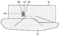
図4には、光源12がロービームのみ照射している場合における自車両前方のイメージ図を図示している。また、図5には、光源12がロービームとハイビームを照射している場合における自車両前方のイメージ図を図示している。なお、図4,5における符号20は、光源12がハイビームで照射可能なハイビーム領域を示しており、符号30は、光源12がロービームで照射可能なロービーム領域を示している。よって、前照灯10の照射可能領域は、ハイビーム領域20とロービーム領域30とになる。 FIG. 4 shows an image diagram in front of the host vehicle when the
また、図4,5は、断面図ではないが、光源12からの光が照射されている領域と照射されていない領域とを明確にするために、光源12からの光が照射されている領域に対してハッチングを施している。更に、本実施形態では、図3など図4,図5以外の図面においても、光源12からの光が照射されている領域にハッチングを施している。 4 and 5 are not cross-sectional views, but in order to clarify a region irradiated with light from the
デジタルミラー13は、複数のミラー131が配列されたものである。このデジタルミラー13は、MEMSミラーと称することができる。また、ミラー131は、マイクロミラーと称することができる。なお、MEMSは、Micro Electro Mechanical Systemsの略称である。また、ミラー131は、ミラー素子、ミラー単体と称することもできる。 The
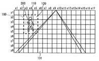
本実施形態では、一例として、図3に示すように、9×17個で153個のミラー131を備えたデジタルミラー13を採用している。つまり、デジタルミラー13は、縦y1からy9、横x1からx17に153個のミラー131が配列されている。しかしながら、デジタルミラー13は、153個よりも多くのミラー131を備えたものであっても、153個よりも少ないミラー131を備えたものであっても採用できる。 In the present embodiment, as an example, as shown in FIG. 3, a
複数のミラー131の夫々は、前照灯制御部11からの制御信号に応じて、オン状態とオフ状態とに切り替え可能に構成されている。各ミラー131は、自身がオン状態の場合は光源12から照射された光を反射して自車両の前方に照射するように構成されている。また、各ミラー131は、自身がオフ状態の場合は光源12から照射された光を自車両の前方に照射しないように構成されている。つまり、前照灯制御部11は、複数のミラー131の夫々を個別にオン及びオフすることで、光源12から照射される光の配光を制御する。 Each of the plurality of
詳述すると、各ミラー131は、オン状態とオフ状態とで自身の角度が異なるものである。オン状態のミラー131は、光源12から照射された光を自車両の前方に反射する角度となっている。一方、オフ状態のミラー131は、光源12から照射された光が自車両の前方に反射しない角度となっている。このため、前照灯制御部11は、デジタルミラー13に対して各ミラー131の角度を指示する制御信号を出力することで、各ミラー131のオン状態とオフ状態とを切り替える制御を行う。 More specifically, each
なお、このデジタルミラー13の詳細に関しては、特許文献1に開示されたDMD(Digital Micromirror Device)などを参照されたい。なお、本実施形態では、デジタルミラー13を用いて、デジタルミラー13におけるミラー131のオン状態及びオフ状態で光源12から照射される光の配光を制御する例を採用している。しかしながら、本発明は、これに限定されない。 For details of the
前方検出部14は、自車両の前方に存在する障害物と、その障害物の位置を検出する装置である。前方検出部14は、例えば、周知のカメラや赤外線センサなどを採用することができる。例えば、カメラを採用した場合、前方検出部14は、自身で撮像した画像と、テンプレートを用いたパターンマッチングなどによって、障害物の有無、及び障害物の位置を検出し、検出結果を前照灯制御部11に知らせる。また、前照灯制御部11と前方検出部14のいずれかは、光源12からの光によって障害物を強調照射するために、前方検出部14で検出された障害物の位置と、各ミラー131の位置とを対応付けることができる。言い換えると、前照灯制御部11と前方検出部14のいずれかは、前方検出部14で検出された障害物の位置と、光源12による光の照射領域における位置とを対応付けることができる。よって、前照灯制御部11は、複数のミラー131のうちどのミラー131をオン状態とすることで、光源12から発せられた光を、前方検出部14で検出された障害物に対して照射可能であるかを把握することができる。 The
なお、本実施形態では、障害物として歩行者200を採用する。しかしながら、障害物は、歩行者に限定されない。障害物は、自車両の前方に存在し、自車両の走行を妨げる可能性があるものであれば採用でき、歩行者以外にも、例えば駐車車両や人間以外の動物なども採用できる。 In the present embodiment, a
ここで、図2〜図5を用いて、前照灯制御部11の処理動作に関して説明する。前照灯制御部11は、光源12の点灯が指示されると図2のフローチャートに示す処理をスタートする。そして、前照灯制御部11は、光源12の点灯が指示される間、処理を繰り返し実行すると共に、光源12の消灯が指示されることで処理を終了する。なお、前照灯制御部11は、車両の乗員によって操作される操作スイッチから光源12の点灯指示がなされてもよいし、車両の周辺の光量を検出するライトセンサから光源12の点灯指示がなされてもよい。同様に、前照灯制御部11は、車両の乗員によって操作される操作スイッチから光源12の消灯指示がなされてもよいし、車両の周辺の光量を検出するライトセンサから光源12の消灯指示がなされてもよい。この操作スイッチ及びライトセンサは図示を省略する。 Here, the processing operation of the
ステップS10では、光源を点灯させる。前照灯制御部11は、光源12の点灯を指示する制御信号を出力する。光源12は、この制御信号に応じて光を照射する。 In step S10, the light source is turned on. The
ステップS11では、障害物の有無を判定する(判定手段)。前照灯制御部11は、前方検出部14からの検出結果に基づいて、自車両の前方における障害物としての歩行者200の有無を判定する。すなわち、前照灯制御部11は、自車両の前方に歩行者200がいるかいないかを判定する。このとき、前照灯制御部11は、前方検出部14からの検出結果に基づいて、歩行者200の位置を判定する。そして、前照灯制御部11は、歩行者200がいると判定した場合はステップS12へ進み、歩行者200がいないと判定した場合はステップS14へ進む。また、前照灯制御部11は、歩行者200がいると判定した場合に、その歩行者200の位置を判定する。 In step S11, the presence or absence of an obstacle is determined (determination means). The
ステップS12では、強調照射領域を設定する(設定手段)。前照灯制御部11は、歩行者200がいると判定した場合、歩行者200を含む領域を強調照射領域100として設定する。言い換えると、前照灯制御部11は、複数のミラー131のうち、歩行者200の位置に対応したミラー131、すなわち、光源12から発せられた光を歩行者200に照射するためのミラー131を特定する。また、強調照射領域とは、領域の周辺領域と異なる態様で光源12からの光を照射する領域である。更に、強調照射領域は、車両の運転者が歩行者200を視認しやすくなるように、光源12からの光を強調させて照射する領域、と言う事ができる。 In step S12, an emphasized irradiation area is set (setting means). When it is determined that the
例えば、図3の例では、前照灯制御部11は、歩行者200を囲う強調照射領域100を設定する。この強調照射領域100は、デジタルミラー13におけるx3y2からx3y5までの四つのミラー131、x4y2からx4y5までの四つのミラー131、x5y2からx5y5までの四つのミラー131が対応している。 For example, in the example of FIG. 3, the
ステップS13では、強調照射領域100を照射範囲110と非照射範囲120に区分けして強調照射する(制御手段)。前照灯制御部11は、強調照射領域100において、照射範囲110と非照射範囲120とが含まれるように光源12から照射される光の配光を制御する。 In step S13, the
前照灯制御部11は、強調照射領域100に、照射範囲110と非照射範囲120とによって、例えば市松模様が表示されるように光源12から照射される光の配光を制御する。この市松模様が表示された強調照射領域100に関しては、図3を参照されたい。詳述すると、前照灯制御部11は、x3y3,x3y5,x4y2,x4y4,x5y3,x5y5の六つのミラー131をオン状態にして照射範囲110を形成する。更に、前照灯制御部11は、x3y2,x3y4,x4y3,x4y5,x5y2,x5y4の六つのミラー131をオフ状態にして非照射範囲120を形成する。 The
一般的な前照灯は、点灯時に市松模様が表示されるように光を照射することはない。よって、前照灯制御部11は、強調照射領域100に市松模様が表示されるように配光を制御することで、歩行者200を強調させることができる。また、前照灯10は、複数のミラー131における一部のミラー131をオン状態とオフ状態とにすることで、強調照射領域100に市松模様を表示するこができるため、簡単に歩行者200を強調させることができる。しかしながら、本発明はこれに限定されない。本発明は、強調照射領域100において、照射範囲110と非照射範囲120とが含まれるように光源12から照射される光の配光を制御するものであれば目的を達成できる。 A general headlamp does not emit light so that a checkered pattern is displayed when it is turned on. Therefore, the
なお、前照灯制御部11は、ロービームとハイビームを照射している場合であり、且つ、歩行者200が領域20にいた場合、図5に示すように強調照射する。また、前照灯制御部11は、ロービームは照射しているが、ハイビームは照射していない場合であり、且つ、歩行者200が領域20にいた場合であっても、図4に示すように強調照射してもよい。つまり、前照灯制御部11は、光源12を点灯中であり、前照灯10の照射可能領域に歩行者200がいた場合であれば強調照射する。 In addition, the
ステップS14では、強制照射をリセットする。つまり、前照灯制御部11は、ステップS14では、運転者に視認させるべき歩行者200がいないとみなして強制照射をリセットする。前照灯制御部11は、既に強調照射領域100を設定及び強調照射を行っている場合は、強調照射領域100の設定を解除すると共に強調照射を停止する。また、前照灯制御部11は、強調照射領域100を設定及び強調照射を行っていない場合は、強調照射領域100の設定及び強調照射を行うことなくステップS11へ戻る。 In step S14, forced irradiation is reset. That is, the
このように、前照灯制御部11は、歩行者200を含む領域を周辺領域と異なる態様で光源12からの光を照射する強調照射領域100とすることで、運転者が視認しやすいように歩行者200に対して光を照射できる。更に、前照灯制御部11は、この強調照射領域100において、照射範囲110と非照射範囲120とが含まれるように光源12から照射される光の配光を制御することで、フラッシングした場合などのように歩行者200に対して瞬間的に光が照射されなくなることを抑制できる。つまり、前照灯制御部11は、歩行者200が強調されるように光源12からの光を照射しつつ、歩行者200の一部に対して常に光源12からの光を照射することができる。言い換えると、前照灯制御部11は、強調照射領域100において、同時に照射範囲110と非照射範囲120とが形成されるように光源12から照射される光の配光を制御する。これによって、前照灯制御部11は、歩行者200に対して瞬間的に光が照射されなくなることによって、運転者が歩行者200を視認し辛くなることを抑制できる。 As described above, the
なお、歩行者200を強調させるためには、照射光を減光しつつフラッシングすることも考えられる。しかしながら、この場合、光度の階調表示するために、PWM制御などの複雑な制御が必要となる。これに対して、前照灯制御部11は、ミラー131をオン状態又はオフ状態にすることで、運転者が視認しやすいように歩行者200に対して光を照射できるため、PWM制御などによってフラッシングする場合よりも制御の容易化が期待できる。つまり、前照灯制御部11は、複雑な階調制御を行うことなく、ミラー131のオンオフ制御のみで、階調制御したフラッシングと同じ効果を実現できる。 In order to emphasize the
また、前照灯制御部11は、ステップS13において、強調照射領域100における表示を周期的に繰り返してもよい。このとき、前照灯制御部11は、照射範囲110を形成するためにオン状態にしているミラー131を周期的にオン状態とオフ状態とにする。又は、前照灯制御部11は、非照射範囲120を形成するためにオフ状態にしているミラー131を周期的にオン状態とオフ状態とにする。つまり、前照灯制御部11は、強調照射領域100における市松模様などの表示を点滅させてもよい。前照灯制御部11は、このようにすることで、強調照射領域100における表示を周期的に繰り返さない場合よりも、歩行者200をより一層強調することができる。しかしながら、本発明はこれに限定されない。 Further, the
また、前照灯制御部11は、ステップS13において、照射範囲110の照度を、光源12から光が照射されている領域であり且つ強調照射領域100とは異なる領域の照度よりも低くなるように制御してもよい。言い換えると、前照灯制御部11は、照射範囲110の周辺において光源12からの光が照射されている領域よりも、照射範囲110が暗くなるように制御する。例えば図4の例の場合、前照灯制御部11は、照射範囲110の照度を、ロービーム領域30の照度よりも低くなるように制御する。なお、照射範囲110の照度を低下させる方法は、特に限定されない。例えば、前照灯制御部11は、照射範囲110を形成するためにオン状態にしているミラー131を照度が低下する程度の速さでオン状態とオフ状態を切り替える。前照灯制御部11は、このようにすることで、歩行者200の幻惑を抑制しつつ、歩行者200を強調することができる。しかしながら、本発明はこれに限定されない。 In step S13, the
なお、本実施形態においては、前照灯制御部11と、光源12と、デジタルミラー131、前方検出部14を備えた前照灯10を採用した。しかしながら、前照灯10は、前方検出部14を備えていなくても目的を達成できる。つまり、前照灯10は、前照灯制御部11が前方検出部14の検出結果を取得可能であれば、前方検出部14を備えていなくても目的を達成できる。 In the present embodiment, the
以上、本発明の好ましい実施形態について説明した。しかしながら、本発明は、上述した実施形態に何ら制限されることはなく、本発明の趣旨を逸脱しない範囲において、種々の変形が可能である。以下に、本発明の変形例1〜5に関して説明する。上述の実施形態及び変形例1〜5は、夫々単独で実施することも可能であるが、適宜組み合わせて実施することも可能である。発明は、実施形態において示された組み合わせに限定されることなく、種々の組み合わせによって実施可能である。 The preferred embodiments of the present invention have been described above. However, the present invention is not limited to the embodiments described above, and various modifications can be made without departing from the spirit of the present invention. Below, the modifications 1-5 of this invention are demonstrated. The above-described embodiment and
(変形例1)
次に、図6を用いて、変形例1に関して説明する。なお、変形例1においては、便宜上、上述の実施形態と同じ符号を用いて説明する。(Modification 1)
Next,
前照灯制御部11は、強調照射領域100において、歩行者200の輪郭を周期的に明減するように光源12から照射される光の配光を制御してもよい(制御手段)。つまり、前照灯制御部11は、強調照射領域100において、歩行者200の輪郭を点滅させるように光源12から照射される光の配光を制御してもよい。 The
ここでは、図6に示すように、前照灯制御部11が強調照射領域100を設定した場合を一例として採用している。この強調照射領域100は、デジタルミラー13におけるx3y1からx3y6までの六つのミラー131、x4y1からx4y6までの六つのミラー131、x5y1からx5y6までの六つのミラー131が対応している。前照灯制御部11は、時間の経過に応じて、これらのミラー131のうち、一部のミラー131をオン状態とオフ状態とに切り替える。 Here, as shown in FIG. 6, the case where the
詳述すると、前照灯制御部11は、タイミングt1において、x4y2からx4y5の四つのミラー131をオン状態にして照射範囲110を形成する。また、前照灯制御部11は、タイミングt1において、x3y1からx3y6、x4y1,x4y6,x5y1からx5y6の十四のミラー131をオフ状態にして非照射範囲120を形成する。 More specifically, the
その後、前照灯制御部11は、タイミングt1からタイミングt2に切り替わると、x4y2からx4y5の四つのミラー131をオン状態で継続して照射範囲110を形成する。また、前照灯制御部11は、タイミングt1からタイミングt2に切り替わると、x3y1からx3y6、x4y1,x4y6,x5y1からx5y6の十四のミラー131をオフ状態からオン状態に切り替える。これによって、前照灯制御部11は、タイミングt1で非照射範囲120だった領域に、光源12からの光を照射させる。つまり、前照灯制御部11は、タイミングt2において、x3y1からx3y6、x4y1,x4y6,x5y1からx5y6の十四のミラー131をオン状態とすることで照射範囲110を形成する。 Thereafter, when the
前照灯制御部11は、このタイミングt1での制御とタイミングt2での制御とを順番に繰り返し実行することで、歩行者200の輪郭を点滅させるように光源12から照射される光の配光を制御する。このように、前照灯制御部11は、歩行者200の輪郭を照射範囲110と非照射範囲120とに切り替える、と言う事ができる。この変形例1においても、上述の実施形態と同様の効果を奏することができる。更に、前照灯制御部11は、歩行者200の輪郭を点滅させることで、歩行者200をより一層強調することができる。 The
(変形例2)
次に、図7を用いて、変形例2に関して説明する。なお、変形例2においては、便宜上、上述の実施形態と同じ符号を用いて説明する。(Modification 2)
Next,
前照灯制御部11は、図7に示すように、強調照射領域100に、照射範囲110と非照射範囲120とによって幾何学的模様が表示されるように光源12から照射される光の配光を制御してもよい。ここでは、図7に示すように、前照灯制御部11が上述の実施形態と同様の範囲を強調照射領域100として設定した場合を一例として採用している。 As shown in FIG. 7, the
そして、前照灯制御部11は、x3y3,x3y4,x4y2,x4y5,x5y3,x5y4の六つのミラー131をオン状態にして照射範囲110を形成する。また、前照灯制御部11は、x3y2,x3y5,x4y3,x4y4,x5y2,x5y5の六つのミラー131をオフ状態にして非照射範囲120を形成する。この変形例1においても、上述の実施形態と同様の効果を奏することができる。 Then, the
また、前照灯制御部11は、上述の実施形態と同様に、強調照射領域100における表示を周期的に繰り返してもよい。このようにしても、上述の実施形態と同様の効果を奏することができる。 Further, the
(変形例3)
次に、図8を用いて、変形例3に関して説明する。なお、変形例3においては、便宜上、上述の実施形態と同じ符号を用いて説明する。(Modification 3)
Next,
前照灯制御部11は、強調照射領域100における表示を動かすようにしてもよい。つまり、前照灯制御部11は、強調照射領域100において、照射範囲110と非照射範囲120とが移動するように光源12から照射される光の配光を制御する。ここでは、図8に示すように、前照灯制御部11が上述の実施形態と同様の範囲を強調照射領域100として設定した場合を一例として採用している。 The
そして、前照灯制御部11は、タイミングt11において、x3y2からx3y5,x5y2からx5y5の八つのミラー131をオン状態にして照射範囲110を形成する。また、前照灯制御部11は、タイミングt11において、x4y2からx4y5の四つのミラー131をオフ状態にして非照射範囲120を形成する。 The
その後、前照灯制御部11は、タイミングt11からタイミングt12に切り替わると、x4y2からx4y5,x5y2からx5y5の八つのミラー131をオン状態にして照射範囲110を形成する。また、前照灯制御部11は、タイミングt11からタイミングt12に切り替わると、x3y2からx3y5の四つのミラー131をオフ状態にして非照射範囲120を形成する。 Thereafter, when the
更に、その後、前照灯制御部11は、タイミングt12からタイミングt13に切り替わると、x3y2からx3y5,x4y2からx4y5の八つのミラー131をオン状態にして照射範囲110を形成する。また、前照灯制御部11は、タイミングt12からタイミングt13に切り替わると、x5y2からx5y5の四つのミラー131をオフ状態にして非照射範囲120を形成する。 Further, after that, when the
前照灯制御部11は、このタイミングt11での制御、タイミングt12での制御、タイミングt13での制御を順番に繰り返し実行することで、照射範囲110と非照射範囲120とが移動するように光源12から照射される光の配光を制御する。この変形例3においても、上述の実施形態と同様の効果を奏することができる。更に、前照灯制御部11は、照射範囲110と非照射範囲120とを移動させることで、歩行者200をより一層強調することができる。なお、照射範囲110と非照射範囲120の移動態様は、これに限定されない。 The
(変形例4)
次に、図9,図10を用いて、変形例4に関して説明する。なお、変形例4においては、便宜上、上述の実施形態と同じ符号を用いて説明する。また、図9のフローチャートに関しては、図2と同じ処理には同じステップ番号を付与して説明を省略する。(Modification 4)
Next,
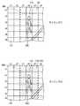
前照灯制御部11は、障害物の種別毎に、強調照射領域100に対する光源12から照射される光の配光を異ならせてもよい。この場合、前照灯制御部11は、ステップS11で障害物が有りと判定された場合、その障害物の種別を特定する(特定手段)。このとき、前照灯制御部11は、前方検出部14からの検出結果に基づいて、障害物の種別を特定する。また、前方検出部14は、自身で撮像した画像と、テンプレートを用いたパターンマッチングなどによって、障害物の種別を判定する。そして、前方検出部14は、その判定結果を前照灯制御部11に知らせる。なお、前照灯制御部11は、前方検出部14としてのカメラで撮像された画像と、テンプレートを用いたパターンマッチングなどによって、障害物の種別を特定してもよい。なお、ここでは、障害物の一例として、歩行者200と駐車車両210とを採用している。しかしながら、障害物は、歩行者200や駐車車両210に限定されない。 The
ここで、図9を用いて、変形例4の前照灯制御部11の処理動作に関して説明する。前照灯制御部11は、ステップS12での処理を終えると、ステップS15の判定を行う。そして、前照灯制御部11は、障害物が歩行者200であると判定した場合はステップS13aへ進み、障害物が駐車車両210であると判定した場合はステップS13bへ進む(特定手段)。なお、図10に示すように、障害物として歩行者200と駐車車両210の両方が存在した場合、前照灯制御部11は、ステップS13aとS13bを並行して実行する。 Here, the processing operation of the
ステップS13aでは、前照灯制御部11は、強調照射領域を歩行者200に対応した第1態様で強調照射する(制御手段)。一方、ステップS13aでは、前照灯制御部11は、強調照射領域を駐車車両210に対応した第2態様で強調照射する(制御手段)。 In step S <b> 13 a, the
なお、特定結果としての歩行者200と第1態様、及び特定結果としての第2態様は、予め対応付けられて、前照灯制御部11の記憶部などに記憶されている。つまり、前照灯制御部11は、ステップS15において障害物の種別を特定すると、自身の記憶部などを参照することで、どの態様で強調照射するのかを把握できる。言い換えると、前照灯制御部11は、障害物の種別を特定すると、自身の記憶部などを参照することで、複数のミラー131の夫々をどのようにオン状態及びオフ状態にするかを把握できる。 In addition, the
図10では、前照灯制御部11が歩行者200に対する強調照射領域100と、駐車車両210に対する強調照射領域100とを設定した場合を一例として採用している。前照灯制御部11は、歩行者200に対しては強調照射領域100に市松模様が表示されるように配光を制御し、駐車車両210に対しては強調照射領域100に縦線模様が表示されるように配光を制御する。なお、歩行者200に対する強調照射領域100は、上述の実施形態と同様のミラー131が対応している。一方、駐車車両210に対する強調照射領域100は、デジタルミラー13におけるx7y2,x7y3,x8y2,x8y3,x9y2,x9y3の六つのミラー131が対応している。 In FIG. 10, the case where the
詳述すると、前照灯制御部11は、x3y3,x3y5,x4y2,x4y4,x5y3,x5y5の六つのミラー131をオン状態にして、歩行者200を含む強調照射領域100における照射範囲110を形成する。また、前照灯制御部11は、x3y2,x3y4,x4y3,x4y5,x5y2,x5y4の六つのミラー131をオフ状態にして、歩行者200を含む強調照射領域100における非照射範囲120を形成する。 Specifically, the
更に、前照灯制御部11は、x8y2,x8y3の二つのミラー131をオン状態にして、駐車車両210を含む強調照射領域100における照射範囲110を形成する。また、前照灯制御部11は、x7y2,x7y3,x9y2,x9y3の四つのミラー131をオフ状態にして、駐車車両210を含む強調照射領域100における非照射範囲120を形成する。 Further, the
この変形例4においても、上述の実施形態と同様の効果を奏することができる。更に、前照灯制御部11は、障害物の種別を運転者に知らせることができる。なお、本発明はこれに限定されない。障害物は、三種類以上の種別に区分けしてもよい。また、各種別に対応する強調照射の態様は、変形例1〜3で説明した態様を採用することもできる。例えば、前照灯制御部11は、歩行者200に対する強調照射領域100に変形例1で説明したように表示すべく配光を制御し、駐車車両210に対する強調照射領域100に市松模様を表示すべく配光を制御してもよい。 Also in this
(変形例5)
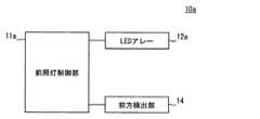
次に、図11を用いて、変形例5に関して説明する。なお、変形例5における前方検出部は、上述の実施形態と同じであるため、同じ符号を用いている。(Modification 5)
Next,
前照灯10aは、前照灯制御部11aと、LEDアレー12aと、前方検出部14とを備えて構成されている。つまり、前照灯10aは、光源12とデジタルミラー13のかわりに、LEDアレー12aを備えている。 The
また、LEDアレー12aは、周知技術であり、光源として複数のLEDを備えている。LEDは、特許請求の範囲における発光素子である。なお、発光素子は、レーザーダイオードなどを採用することもできる。 The
前照灯制御部11aは、複数のLEDの夫々を個別にオン及びオフすることで、LEDから照射される光の配光を制御する(制御手段)。つまり、前照灯制御部11aは、複数のLEDの夫々を個別にオン及びオフすることで、前照灯制御部11と同様に配光を制御する(制御手段)。 The
この変形例5においても、上述の実施形態と同様の効果を奏することができる。更に、前照灯制御部11aは、複数のLEDの夫々を個別にオン及びオフするものであるため、前照灯制御部11よりも照度の調整を容易に行うことができる。例えば、前照灯制御部11aは、照射範囲110の周辺においてLEDアレー12aからの光が照射されている領域よりも、照射範囲110が暗くなるように制御する際に、前照灯制御部11よりも制御が容易である。 Also in this
なお、上述の実施形態及び変形例1〜5においては、デジタルミラー13やLEDアレー12aによって、光源から照射される光の配光を制御する例を採用した。しかしながら、本発明は、これに限定されない。本発明は、光源から照射される光の配光を制御できれば、デジタルミラー13やLEDアレー12a以外を用いてもよい。 In the above-described embodiment and
10,10a 前照灯、11,11a 前照灯制御部、12 光源、12a LEDアレー、13 デジタルミラー、14 前方検出部 10, 10a headlamp, 11, 11a headlamp controller, 12 light source, 12a LED array, 13 digital mirror, 14 forward detector
Claims (16)
Translated fromJapanese自車両の前方における障害物の有無、及び該障害物の位置を判定する判定手段(S11)と、
前記判定手段にて前記障害物が存在すると判定された場合、前記障害物を含む領域を、該領域の周辺領域と異なる態様で前記光源からの光を照射する強調照射領域として設定する設定手段(S12)と、
前記設定手段にて設定された前記強調照射領域において、照射範囲と非照射範囲とが含まれるように前記光源から照射される光の配光を制御する制御手段(S13,S13a,S13b)と、を備え、
前記制御手段は、前記強調照射領域に、前記照射範囲と前記非照射範囲とによって市松模様が表示されるように前記光源から照射される光の配光を制御することを特徴とする前照灯制御装置。A headlamp control device for controlling a headlamp provided in a vehicle, capable of controlling the light distribution of light emitted from a light source,
Determination means (S11) for determining the presence or absence of an obstacle in front of the host vehicle and the position of the obstacle;
Setting means for setting the area including the obstacle as an emphasized irradiation area for irradiating light from the light source in a manner different from the peripheral area of the area when the determination means determines that the obstacle exists. S12)
Control means (S13, S13a, S13b) for controlling the light distribution of the light emitted from the light source so that the irradiation range and the non-irradiation range are included in the emphasized irradiation region set by the setting unit; equipped witha,
The control means controls a light distribution of light emitted from the light source so that a checkered pattern is displayed in the emphasized irradiation region by the irradiation range and the non-irradiation range. Control device.
自車両の前方における障害物の有無、及び該障害物の位置を判定する判定手段(S11)と、
前記判定手段にて前記障害物が存在すると判定された場合、前記障害物を含む領域を、該領域の周辺領域と異なる態様で前記光源からの光を照射する強調照射領域として設定する設定手段(S12)と、
前記設定手段にて設定された前記強調照射領域において、照射範囲と非照射範囲とが含まれるように前記光源から照射される光の配光を制御する制御手段(S13,S13a,S13b)と、を備え、
前記制御手段は、前記強調照射領域において、前記障害物の輪郭を周期的に明減するように前記光源から照射される光の配光を制御することを特徴とする前照灯制御装置。A headlamp control device for controlling a headlamp provided in a vehicle, capable of controlling the light distribution of light emitted from a light source,
Determination means (S11) for determining the presence or absence of an obstacle in front of the host vehicle and the position of the obstacle;
Setting means for setting the area including the obstacle as an emphasized irradiation area for irradiating light from the light source in a manner different from the peripheral area of the area when the determination means determines that the obstacle exists. S12)
Control means (S13, S13a, S13b) for controlling the light distribution of the light emitted from the light source so that the irradiation range and the non-irradiation range are included in the emphasized irradiation region set by the setting unit; With
Wherein, said at highlighting the irradiation area, the obstacle contour periodicallyheadlamp controlleryou and controlling the light distribution of the light emitted from the light source so asto decrease light.
自車両の前方における障害物の有無、及び該障害物の位置を判定する判定手段(S11)と、
前記判定手段にて前記障害物が存在すると判定された場合、前記障害物を含む領域を、該領域の周辺領域と異なる態様で前記光源からの光を照射する強調照射領域として設定する設定手段(S12)と、
前記設定手段にて設定された前記強調照射領域において、照射範囲と非照射範囲とが含まれるように前記光源から照射される光の配光を制御する制御手段(S13,S13a,S13b)と、を備え、
前記制御手段は、前記照射範囲の照度を、前記光源から光が照射されている領域であり且つ前記強調照射領域とは異なる領域の照度よりも低くなるように制御することを特徴とする前照灯制御装置。A headlamp control device for controlling a headlamp provided in a vehicle, capable of controlling the light distribution of light emitted from a light source,
Determination means (S11) for determining the presence or absence of an obstacle in front of the host vehicle and the position of the obstacle;
Setting means for setting the area including the obstacle as an emphasized irradiation area for irradiating light from the light source in a manner different from the peripheral area of the area when the determination means determines that the obstacle exists. S12)
Control means (S13, S13a, S13b) for controlling the light distribution of the light emitted from the light source so that the irradiation range and the non-irradiation range are included in the emphasized irradiation region set by the setting unit; With
The control means, the illuminance of the irradiation range,before you and controlsto be lower than the illuminance of the area different from the a region where light is irradiated from the light source and the enhancement irradiation region Lighting control device.
自車両の前方における障害物の有無、及び該障害物の位置を判定する判定手段(S11)と、
前記判定手段にて前記障害物が存在すると判定された場合、前記障害物を含む領域を、該領域の周辺領域と異なる態様で前記光源からの光を照射する強調照射領域として設定する設定手段(S12)と、
前記設定手段にて設定された前記強調照射領域において、照射範囲と非照射範囲とが含まれるように前記光源から照射される光の配光を制御する制御手段(S13,S13a,S13b)と、を備え、
前記制御手段は、前記強調照射領域において、前記照射範囲と前記非照射範囲とが移動するように前記光源から照射される光の配光を制御することを特徴とする前照灯制御装置。A headlamp control device for controlling a headlamp provided in a vehicle, capable of controlling the light distribution of light emitted from a light source,
Determination means (S11) for determining the presence or absence of an obstacle in front of the host vehicle and the position of the obstacle;
Setting means for setting the area including the obstacle as an emphasized irradiation area for irradiating light from the light source in a manner different from the peripheral area of the area when the determination means determines that the obstacle exists. S12)
Control means (S13, S13a, S13b) for controlling the light distribution of the light emitted from the light source so that the irradiation range and the non-irradiation range are included in the emphasized irradiation region set by the setting unit; With
Wherein, the enhancement in the irradiated region, the irradiated area and the non-irradiation range and theheadlamp control apparatusyou andcontrolling the light distribution of the light emitted from the light source to move.
自車両の前方における障害物の有無、及び該障害物の位置を判定する判定手段(S11)と、
前記判定手段にて前記障害物が存在すると判定された場合、前記障害物を含む領域を、該領域の周辺領域と異なる態様で前記光源からの光を照射する強調照射領域として設定する設定手段(S12)と、
前記設定手段にて設定された前記強調照射領域において、照射範囲と非照射範囲とが含まれるように前記光源から照射される光の配光を制御する制御手段(S13,S13a,S13b)と、を備え、
前記制御手段は、前記強調照射領域における表示を周期的に繰り返すことを特徴とする前照灯制御装置。A headlamp control device for controlling a headlamp provided in a vehicle, capable of controlling the light distribution of light emitted from a light source,
Determination means (S11) for determining the presence or absence of an obstacle in front of the host vehicle and the position of the obstacle;
Setting means for setting the area including the obstacle as an emphasized irradiation area for irradiating light from the light source in a manner different from the peripheral area of the area when the determination means determines that the obstacle exists. S12)
Control means (S13, S13a, S13b) for controlling the light distribution of the light emitted from the light source so that the irradiation range and the non-irradiation range are included in the emphasized irradiation region set by the setting unit; With
It said control means,you andrepeating the display of the highlighted irradiation region cyclicallyheadlamp controller.
前記制御手段(S13a,S13b)は、前記特定手段にて特定された種別毎に、前記強調照射領域に対する前記光源から照射される光の配光を異ならせることを特徴とする請求項1乃至11のいずれか一項に記載の前照灯制御装置。The said control means (S13a, S13b) varies the light distribution of the light irradiated from the said light source with respect to the said emphasis irradiation area | region for every classification specified by the said specification means. The headlamp control device according to any one of the above.
複数の前記ミラーの夫々は、自身がオン状態の場合は前記光源から照射された光を反射して自車両の前方に照射し、自身がオフ状態の場合は前記光源から照射された光を自車両の前方に照射しないものであって、Each of the plurality of mirrors reflects light emitted from the light source when it is turned on and irradiates the front of the host vehicle, and when it is turned off, each of the mirrors emits light emitted from the light source. It does not irradiate the front of the vehicle,
前記制御手段は、複数の前記ミラーの夫々を個別にオン状態及びオフ状態とすることで、前記光源から照射される光の配光を制御することを特徴とする請求項1乃至12のいずれか一項に記載の前照灯制御装置。The said control means controls the light distribution of the light irradiated from the said light source by making each of several said mirrors into an ON state and an OFF state individually. The headlamp control device according to one item.
前記制御手段は、複数の前記発光素子の夫々を個別にオン及びオフすることで、前記光源から照射される光の配光を制御することを特徴とする請求項1乃至12のいずれか一項に記載の前照灯制御装置。The said control means controls the light distribution of the light irradiated from the said light source by turning on and off each of the said several light emitting element separately, The any one of Claims 1 thru | or 12 characterized by the above-mentioned. The headlight control device described in 1.
Priority Applications (5)
| Application Number | Priority Date | Filing Date | Title |
|---|---|---|---|
| JP2014016914AJP6264909B2 (en) | 2014-01-31 | 2014-01-31 | Headlamp control device and headlamp |
| PCT/JP2015/000323WO2015115083A1 (en) | 2014-01-31 | 2015-01-26 | Headlight control device and headlight |
| US15/103,960US9815400B2 (en) | 2014-01-31 | 2015-01-26 | Headlight control device and headlight |
| EP15743713.8AEP3100908A4 (en) | 2014-01-31 | 2015-01-26 | Headlight control device and headlight |
| CN201580006443.4ACN105939892B (en) | 2014-01-31 | 2015-01-26 | Headlamp control device and headlamp |
Applications Claiming Priority (1)
| Application Number | Priority Date | Filing Date | Title |
|---|---|---|---|
| JP2014016914AJP6264909B2 (en) | 2014-01-31 | 2014-01-31 | Headlamp control device and headlamp |
Publications (2)
| Publication Number | Publication Date |
|---|---|
| JP2015143065A JP2015143065A (en) | 2015-08-06 |
| JP6264909B2true JP6264909B2 (en) | 2018-01-24 |
Family
ID=53756664
Family Applications (1)
| Application Number | Title | Priority Date | Filing Date |
|---|---|---|---|
| JP2014016914AExpired - Fee RelatedJP6264909B2 (en) | 2014-01-31 | 2014-01-31 | Headlamp control device and headlamp |
Country Status (5)
| Country | Link |
|---|---|
| US (1) | US9815400B2 (en) |
| EP (1) | EP3100908A4 (en) |
| JP (1) | JP6264909B2 (en) |
| CN (1) | CN105939892B (en) |
| WO (1) | WO2015115083A1 (en) |
Families Citing this family (19)
| Publication number | Priority date | Publication date | Assignee | Title |
|---|---|---|---|---|
| JP6075331B2 (en)* | 2014-06-13 | 2017-02-08 | トヨタ自動車株式会社 | Vehicle lighting device |
| JP5955356B2 (en)* | 2014-08-01 | 2016-07-20 | 株式会社豊田中央研究所 | Lighting device |
| FR3042844A1 (en)* | 2015-09-14 | 2017-04-28 | Valeo Vision | LIGHTING SYSTEM FOR MOTOR VEHICLES |
| JP6941916B2 (en)* | 2015-12-28 | 2021-09-29 | 凸版印刷株式会社 | Scanning headlights, scanning headlight control methods and programs |
| US10180224B2 (en)* | 2016-07-26 | 2019-01-15 | Texas Instruments Incorporated | Quasi-sparse optical illumination |
| JP6278217B1 (en)* | 2016-10-24 | 2018-02-14 | マツダ株式会社 | Vehicle headlight control device |
| JP6311768B1 (en) | 2016-10-24 | 2018-04-18 | マツダ株式会社 | Vehicle headlight control device |
| JP6923310B2 (en)* | 2016-11-29 | 2021-08-18 | 株式会社小糸製作所 | Vehicle lamp lighting control device |
| JP6839006B2 (en)* | 2017-03-21 | 2021-03-03 | 株式会社デンソー | Vehicle driving support device and driving support method |
| JP6557843B1 (en)* | 2018-12-05 | 2019-08-14 | パナソニックIpマネジメント株式会社 | VEHICLE CONTROL DEVICE, CONTROL SYSTEM, AND CONTROL PROGRAM |
| JP7159843B2 (en)* | 2018-12-17 | 2022-10-25 | 市光工業株式会社 | Variable light distribution headlight |
| JP7260341B2 (en)* | 2019-03-06 | 2023-04-18 | スタンレー電気株式会社 | Vehicle lighting control device, vehicle lighting control method, vehicle lighting system |
| CN110077313B (en)* | 2019-05-20 | 2020-11-27 | 北京经纬恒润科技有限公司 | Automobile headlamp system and control method |
| CN110303979A (en)* | 2019-07-12 | 2019-10-08 | 爱驰汽车有限公司 | Control method, system, electronic equipment and the storage medium of headlamp |
| FR3099541B1 (en)* | 2019-07-31 | 2024-09-20 | Valeo Vision | METHOD FOR CONTROLLING A LIGHTING DEVICE CAPABLE OF EMITTING TWO PIXELATED LIGHT BEAMS OF DIFFERENT RESOLUTIONS |
| KR102245384B1 (en)* | 2019-09-30 | 2021-04-28 | 현대모비스 주식회사 | Apparatus for controlling beam pattern of head lamp for vehicle and method thereof |
| DE102020101710B4 (en)* | 2020-01-24 | 2021-09-02 | Audi Aktiengesellschaft | Method for illuminating the surroundings of a vehicle and a motor vehicle |
| FR3119009A1 (en)* | 2021-01-21 | 2022-07-22 | Psa Automobiles Sa | Method for controlling a motor vehicle headlamp |
| CN116257015B (en)* | 2023-03-22 | 2023-08-11 | 杭州亿达时科技发展有限公司 | Stage light following lamp intelligent control system based on big data |
Family Cites Families (15)
| Publication number | Priority date | Publication date | Assignee | Title |
|---|---|---|---|---|
| JP4433887B2 (en)* | 2003-07-01 | 2010-03-17 | 日産自動車株式会社 | Vehicle external recognition device |
| JP4881255B2 (en)* | 2007-08-13 | 2012-02-22 | 株式会社小糸製作所 | Vehicle headlamp |
| US8017898B2 (en)* | 2007-08-17 | 2011-09-13 | Magna Electronics Inc. | Vehicular imaging system in an automatic headlamp control system |
| JP5151452B2 (en) | 2007-12-19 | 2013-02-27 | 株式会社豊田中央研究所 | Information display device |
| DE102009026571A1 (en)* | 2009-05-29 | 2010-12-02 | Robert Bosch Gmbh | Method and device for vehicle-based lighting in poorly lit traffic environments |
| JP5415237B2 (en)* | 2009-11-25 | 2014-02-12 | 株式会社小糸製作所 | Vehicle headlight system |
| DE202010006097U1 (en)* | 2009-12-22 | 2010-08-05 | Automotive Lighting Reutlingen Gmbh | Light module for a motor vehicle headlight |
| CN103249597B (en)* | 2010-08-06 | 2015-04-29 | 丰田自动车株式会社 | Vehicle light distribution control device and method |
| DE102011081382A1 (en)* | 2011-08-23 | 2013-02-28 | Robert Bosch Gmbh | Method and device for changing a light emission of at least one headlight of a vehicle |
| KR20130047214A (en)* | 2011-10-31 | 2013-05-08 | 현대자동차주식회사 | Spot lighting unit, headlamp system with spot lighting unit, and lighting method using thereof |
| JP6180093B2 (en)* | 2012-02-24 | 2017-08-16 | 株式会社小糸製作所 | Headlamp device and headlamp control system |
| JP5831302B2 (en)* | 2012-03-08 | 2015-12-09 | トヨタ自動車株式会社 | Multi-light headlight |
| JP5907384B2 (en)* | 2012-06-27 | 2016-04-26 | スタンレー電気株式会社 | Vehicle headlamp |
| JP5992278B2 (en) | 2012-09-20 | 2016-09-14 | スタンレー電気株式会社 | Lighting control device for vehicle headlamp, vehicle headlamp system |
| JP2014184851A (en)* | 2013-03-22 | 2014-10-02 | Toyota Central R&D Labs Inc | Irradiation device |
- 2014
- 2014-01-31JPJP2014016914Apatent/JP6264909B2/ennot_activeExpired - Fee Related
- 2015
- 2015-01-26CNCN201580006443.4Apatent/CN105939892B/ennot_activeExpired - Fee Related
- 2015-01-26WOPCT/JP2015/000323patent/WO2015115083A1/ennot_activeCeased
- 2015-01-26EPEP15743713.8Apatent/EP3100908A4/ennot_activeWithdrawn
- 2015-01-26USUS15/103,960patent/US9815400B2/enactiveActive
Also Published As
| Publication number | Publication date |
|---|---|
| EP3100908A1 (en) | 2016-12-07 |
| EP3100908A4 (en) | 2017-10-25 |
| US20160368413A1 (en) | 2016-12-22 |
| JP2015143065A (en) | 2015-08-06 |
| CN105939892B (en) | 2018-11-06 |
| CN105939892A (en) | 2016-09-14 |
| US9815400B2 (en) | 2017-11-14 |
| WO2015115083A1 (en) | 2015-08-06 |
Similar Documents
| Publication | Publication Date | Title |
|---|---|---|
| JP6264909B2 (en) | Headlamp control device and headlamp | |
| JP6372376B2 (en) | Headlight control device | |
| JP4240110B2 (en) | VEHICLE LIGHTING DEVICE, VEHICLE LIGHTING CONTROL METHOD, AND VEHICLE LIGHTING CONTROL PROGRAM | |
| US9732926B2 (en) | Illumination system for generating a boundary between a shaded area and an irradiated area | |
| JP6770790B2 (en) | Vehicle drawing device | |
| JP4872611B2 (en) | Vehicle lighting device | |
| JP5831302B2 (en) | Multi-light headlight | |
| WO2015033764A1 (en) | Vehicular lighting | |
| JP2008149809A (en) | Vehicle lighting device | |
| JP2009154615A (en) | Vehicle lighting device | |
| JP2015174551A (en) | Vehicle headlight system | |
| JP2012166652A (en) | Lighting control device of vehicle headlight, vehicle headlight system | |
| JP2013109911A (en) | Lighting device | |
| JP2016083987A (en) | Vehicle lighting device, in-vehicle system | |
| JP2006011671A (en) | Vehicle-mounted surrounding circumstance detection device | |
| JP2008100541A (en) | Vehicle lighting device | |
| JP7137414B2 (en) | vehicle lamp | |
| JP6384428B2 (en) | Vehicle headlamp device | |
| JP7052165B2 (en) | Headlight controller | |
| JP7442528B2 (en) | Vehicle lighting system, vehicle lighting control device, and vehicle lighting control method | |
| JP7000084B2 (en) | Vehicle headlight control device | |
| JP2013043617A (en) | Lighting control device of vehicle headlamp, and vehicle headlamp system | |
| JP6409847B2 (en) | Vehicle headlight control device | |
| JP4735555B2 (en) | Vehicle lighting device | |
| JP6348387B2 (en) | Control method for vehicle headlamp system |
Legal Events
| Date | Code | Title | Description |
|---|---|---|---|
| A621 | Written request for application examination | Free format text:JAPANESE INTERMEDIATE CODE: A621 Effective date:20160805 | |
| A131 | Notification of reasons for refusal | Free format text:JAPANESE INTERMEDIATE CODE: A131 Effective date:20170627 | |
| A521 | Request for written amendment filed | Free format text:JAPANESE INTERMEDIATE CODE: A523 Effective date:20170823 | |
| TRDD | Decision of grant or rejection written | ||
| A01 | Written decision to grant a patent or to grant a registration (utility model) | Free format text:JAPANESE INTERMEDIATE CODE: A01 Effective date:20171128 | |
| A61 | First payment of annual fees (during grant procedure) | Free format text:JAPANESE INTERMEDIATE CODE: A61 Effective date:20171211 | |
| R150 | Certificate of patent or registration of utility model | Ref document number:6264909 Country of ref document:JP Free format text:JAPANESE INTERMEDIATE CODE: R150 | |
| LAPS | Cancellation because of no payment of annual fees |