JP6257930B2 - Ultrasonic diagnostic apparatus and ultrasonic probe - Google Patents
Ultrasonic diagnostic apparatus and ultrasonic probeDownload PDFInfo
- Publication number
- JP6257930B2 JP6257930B2JP2013126815AJP2013126815AJP6257930B2JP 6257930 B2JP6257930 B2JP 6257930B2JP 2013126815 AJP2013126815 AJP 2013126815AJP 2013126815 AJP2013126815 AJP 2013126815AJP 6257930 B2JP6257930 B2JP 6257930B2
- Authority
- JP
- Japan
- Prior art keywords
- probe
- unit
- identification information
- ultrasonic
- memory
- Prior art date
- Legal status (The legal status is an assumption and is not a legal conclusion. Google has not performed a legal analysis and makes no representation as to the accuracy of the status listed.)
- Active
Links
Images


Classifications
- A—HUMAN NECESSITIES
- A61—MEDICAL OR VETERINARY SCIENCE; HYGIENE
- A61B—DIAGNOSIS; SURGERY; IDENTIFICATION
- A61B8/00—Diagnosis using ultrasonic, sonic or infrasonic waves
- A61B8/44—Constructional features of the ultrasonic, sonic or infrasonic diagnostic device
- A61B8/4477—Constructional features of the ultrasonic, sonic or infrasonic diagnostic device using several separate ultrasound transducers or probes
- A—HUMAN NECESSITIES
- A61—MEDICAL OR VETERINARY SCIENCE; HYGIENE
- A61B—DIAGNOSIS; SURGERY; IDENTIFICATION
- A61B8/00—Diagnosis using ultrasonic, sonic or infrasonic waves
- A61B8/44—Constructional features of the ultrasonic, sonic or infrasonic diagnostic device
- A61B8/4411—Device being modular
- A—HUMAN NECESSITIES
- A61—MEDICAL OR VETERINARY SCIENCE; HYGIENE
- A61B—DIAGNOSIS; SURGERY; IDENTIFICATION
- A61B8/00—Diagnosis using ultrasonic, sonic or infrasonic waves
- A61B8/44—Constructional features of the ultrasonic, sonic or infrasonic diagnostic device
- A61B8/4438—Means for identifying the diagnostic device, e.g. barcodes
- A—HUMAN NECESSITIES
- A61—MEDICAL OR VETERINARY SCIENCE; HYGIENE
- A61B—DIAGNOSIS; SURGERY; IDENTIFICATION
- A61B8/00—Diagnosis using ultrasonic, sonic or infrasonic waves
- A61B8/44—Constructional features of the ultrasonic, sonic or infrasonic diagnostic device
- A61B8/4483—Constructional features of the ultrasonic, sonic or infrasonic diagnostic device characterised by features of the ultrasound transducer
- A—HUMAN NECESSITIES
- A61—MEDICAL OR VETERINARY SCIENCE; HYGIENE
- A61B—DIAGNOSIS; SURGERY; IDENTIFICATION
- A61B8/00—Diagnosis using ultrasonic, sonic or infrasonic waves
- A61B8/54—Control of the diagnostic device
- A—HUMAN NECESSITIES
- A61—MEDICAL OR VETERINARY SCIENCE; HYGIENE
- A61B—DIAGNOSIS; SURGERY; IDENTIFICATION
- A61B8/00—Diagnosis using ultrasonic, sonic or infrasonic waves
- A61B8/56—Details of data transmission or power supply
- A—HUMAN NECESSITIES
- A61—MEDICAL OR VETERINARY SCIENCE; HYGIENE
- A61B—DIAGNOSIS; SURGERY; IDENTIFICATION
- A61B8/00—Diagnosis using ultrasonic, sonic or infrasonic waves
- A61B8/44—Constructional features of the ultrasonic, sonic or infrasonic diagnostic device
- A61B8/4444—Constructional features of the ultrasonic, sonic or infrasonic diagnostic device related to the probe
Landscapes
- Health & Medical Sciences (AREA)
- Life Sciences & Earth Sciences (AREA)
- Engineering & Computer Science (AREA)
- Heart & Thoracic Surgery (AREA)
- Molecular Biology (AREA)
- Nuclear Medicine, Radiotherapy & Molecular Imaging (AREA)
- Pathology (AREA)
- Radiology & Medical Imaging (AREA)
- Physics & Mathematics (AREA)
- Biomedical Technology (AREA)
- Veterinary Medicine (AREA)
- Medical Informatics (AREA)
- Biophysics (AREA)
- Surgery (AREA)
- Animal Behavior & Ethology (AREA)
- General Health & Medical Sciences (AREA)
- Public Health (AREA)
- Gynecology & Obstetrics (AREA)
- Computer Networks & Wireless Communication (AREA)
- Ultra Sonic Daignosis Equipment (AREA)
Description
Translated fromJapanese本発明の実施形態は、超音波診断装置と超音波プローブとに関する。 Embodiments described herein relate generally to an ultrasonic diagnostic apparatus and an ultrasonic probe.
超音波診断装置の本体には、少なくとも一つの超音波プローブが接続される。超音波プローブのコネクタは、超音波診断装置の本体に対して着脱自在な構造を有する。超音波プローブは、診断対象部位または用途に応じて適宜使い分けられる。超音波プローブの駆動方式は、形式および用途に応じて異なる。このため、超音波プローブは、プローブの各種特性および駆動方式などの超音波プローブ固有の情報を表すプローブ識別子(identification data:以下、IDと呼ぶ)を有する。 At least one ultrasonic probe is connected to the main body of the ultrasonic diagnostic apparatus. The connector of the ultrasonic probe has a structure that is detachable from the main body of the ultrasonic diagnostic apparatus. Ultrasonic probes are appropriately used depending on the site to be diagnosed or application. The driving method of the ultrasonic probe differs depending on the type and application. For this reason, the ultrasonic probe has a probe identifier (identification data: hereinafter referred to as ID) representing information unique to the ultrasonic probe, such as various characteristics and driving methods of the probe.
超音波プローブのコネクタは、プローブIDを超音波診断装置に認識させるための複数のハードワイヤ(hard wire:以下、HWと呼ぶ)を有する。複数のHWは、コネクタ内の複数の記憶回路にそれぞれ接続される。記憶回路は、例えば、開放または接地により、2値信号を記憶する回路である。この2値信号の組合せにより、プローブIDが設定される。 The connector of the ultrasonic probe has a plurality of hard wires (hereinafter referred to as HW) for causing the ultrasonic diagnostic apparatus to recognize the probe ID. The plurality of HWs are connected to the plurality of storage circuits in the connector, respectively. The storage circuit is a circuit that stores a binary signal by, for example, opening or grounding. The probe ID is set by the combination of the binary signals.
超音波プローブが超音波診断装置の本体に接続されたとき、超音波診断装置は、HWワイヤを介して、超音波プローブのプローブIDを取得する。超音波診断装置は、取得したプローブIDにより超音波プローブを識別する。 When the ultrasonic probe is connected to the main body of the ultrasonic diagnostic apparatus, the ultrasonic diagnostic apparatus acquires the probe ID of the ultrasonic probe via the HW wire. The ultrasound diagnostic apparatus identifies the ultrasound probe based on the acquired probe ID.
しかしながら、動作が保証されていないプローブ(例えば、他社プローブ、海賊版など:以下、未保証プローブと呼ぶ)が超音波診断装置の本体に誤って接続された場合、超音波診断装置は、未保証プローブを誤って認識してしまう問題がある。これにより、超音波診断装置と未保証プローブとの間において、適正な超音波プローブの制御および設定などが実施できないため、超音波診断装置の故障、超音波プローブの発熱などによる被検体への危害、および誤診などを招く可能性がある問題がある。 However, if a probe whose operation is not guaranteed (for example, another company's probe, pirated version: hereinafter referred to as an unguaranteed probe) is accidentally connected to the main body of the ultrasound diagnostic apparatus, the ultrasound diagnostic apparatus will There is a problem of misrecognizing. As a result, proper control and setting of the ultrasound probe cannot be performed between the ultrasound diagnostic apparatus and the non-guaranteed probe, resulting in harm to the subject due to failure of the ultrasound diagnostic apparatus, heat generation of the ultrasound probe, etc. There are problems that can lead to misdiagnosis.
目的は、超音波プローブの誤認を防止する超音波診断装置を提供することにある。 An object of the present invention is to provide an ultrasonic diagnostic apparatus that prevents erroneous recognition of an ultrasonic probe.
本実施形態に係る超音波診断装置は、複数の振動子と、プローブ識別情報を記憶するメモリと、プローブ識別子に対応する2値化された電気的状態を発生する2値化状態発生部と、を有する超音波プローブと、前記電気的状態を前記プローブ識別子に変換するプローブ識別子変換部と、前記メモリから前記プローブ識別情報を読み出す読み出し部と、前記変換されたプローブ識別子と前記読み出されたプローブ識別情報との整合性を判定する判定部と、前記判定部による判定結果において前記プローブ識別子と前記プローブ識別情報とが不整合である場合、所定の警告を出力する警告出力部と、を具備し、前記メモリは、プローブ使用履歴情報と前記プローブ使用履歴情報に基づいて暗号化されたプローブ識別情報とをさらに記憶し、前記メモリから前記プローブ識別情報を読み出し、前記プローブ使用履歴情報に基づいて前記プローブ識別情報を解読する読み出し解読部をさらに具備し、前記判定部は、前記変換されたプローブ識別子と前記解読されたプローブ識別情報との整合性を判定し、前記警告出力部は、前記判定部による判定結果において前記プローブ識別子と前記解読されたプローブ識別情報とが不整合である場合、前記所定の警告を出力する。The ultrasonic diagnostic apparatus according to the present embodiment includes a plurality of transducers, a memory that stores probe identification information, a binarized state generating unit that generates a binarized electrical state corresponding to the probe identifier, An ultrasonic probe, a probe identifier conversion unit that converts the electrical state into the probe identifier, a read unit that reads the probe identification information from the memory, the converted probe identifier, and the read probe If a determination unit for determining consistency between the identification information, and the probe identifier in the determination result by the determination unit and the probe identification information is inconsistent,anda warning output unit for outputting a predetermined warningThe memory further stores probe usage history information and probe identification information encrypted based on the probe usage history information. A read decoding unit that reads the probe identification information from the source and decodes the probe identification information based on the probe usage history information, and the determination unit includes the converted probe identifier and the decoded probe identification. The consistency with the information is determined, and the warning output unit outputs the predetermined warning when the probe identifier and the decoded probe identification information are inconsistent in the determination result by the determination unit .
以下、図面を参照しながら本実施形態を説明する。なお、以下の説明において、略同一の構成を有する構成要素については、同一符号を付し、重複説明は必要な場合にのみ行う。 Hereinafter, the present embodiment will be described with reference to the drawings. In the following description, components having substantially the same configuration are denoted by the same reference numerals, and redundant description will be given only when necessary.
(第1の実施形態)
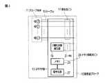
図1は、第1の実施形態に係る超音波診断装置の構成の一例を示す構成図である。同図に示すように、超音波診断装置1は、超音波プローブ10、装置本体30、表示部50、装置本体30に接続され操作者からの各種指示・命令・情報を装置本体30に取り込むための入力部70を有する。加えて本超音波診断装置1には、心電計、心音計、脈波計、呼吸センサに代表される図示していない生体信号計測部およびネットワークが、後述するインターフェース部39を介して接続されてもよい。(First embodiment)
FIG. 1 is a configuration diagram illustrating an example of the configuration of the ultrasonic diagnostic apparatus according to the first embodiment. As shown in FIG. 1, the ultrasonic
超音波プローブ10は、プローブ本体11と、超音波診断装置1の装置本体30に接続されるコネクタ部13と、プローブ本体11とコネクタ部13とを電気的に接続するケーブル15とを有する。 The
プローブ本体11は、複数の振動子と、複数の振動子の前面側に設けられる整合層と、複数の振動子の背面側に設けられるバッキング材とを有する。
複数の振動子各々は、圧電セラミックス等の音響/電気可逆的変換素子である。複数の振動子は並列され、超音波プローブ10の先端に装備される。以下、一つの振動子が一チャンネルを構成するものとして説明する。振動子は、後述する超音波送受信部31から供給された電圧パルスに応答して超音波を発生する。超音波プローブ10を介して被検体に超音波が送信されると、送信された超音波(以下、送信超音波と呼ぶ)は、被検体内の生体組織における音響インピーダンスの不連続面で反射される。振動子は、反射された超音波を受信し、エコー信号を発生する。エコー信号の振幅は、超音波の反射に関する不連続面を境界とする音響インピーダンスの差に依存する。また、送信超音波が移動している血流、および心臓壁等の表面で反射された場合のエコー信号の周波数は、ドプラ効果により、移動体(血流および心臓壁の表面)の超音波送信方向の速度成分に依存して偏移する。The probe
Each of the plurality of vibrators is an acoustic / electric reversible conversion element such as a piezoelectric ceramic. A plurality of transducers are arranged in parallel and are provided at the tip of the
以下、超音波プローブ10は、1次元アレイにより2次元走査するプローブとして説明する。なお、超音波プローブ10は、1次元アレイを複数の振動子の配列方向と直交する方向に揺動させて3次元走査を実行するメカニカル4次元プローブであってもよい。また、超音波プローブ10は、メカニカル4次元プローブに限定されず、2次元アレイプローブであってもよい。 Hereinafter, the
整合層は、被検体に対する超音波の送受信を効率よくするために、複数の振動子の前面側に設けられる。なお、整合層の前面側には、図示していない音響レンズが設けられる。バッキング材は、振動子の後方への超音波の伝搬を防止する。 The matching layer is provided on the front side of the plurality of transducers in order to efficiently transmit and receive ultrasonic waves to and from the subject. An acoustic lens (not shown) is provided on the front side of the matching layer. The backing material prevents the propagation of ultrasonic waves to the back of the transducer.
コネクタ部13は、複数の信号用ピン17と、2値化状態発生部19と、2値化状態発生部19と装置本体30の後述するプローブ識別子変換部41とを電気的に接続するハードワイヤ21(hard wire:以下、HWと呼ぶ)と、メモリ23と、メモリ23と装置本体30の後述する読み出し部43とを電気的に接続するためのメモリ接続用ピンとを有する。 The connector unit 13 is a hard wire that electrically connects the plurality of signal pins 17, the binarized
複数の信号用ピン17各々は、超音波プローブ10が装置本体30に接続されると、装置本体30における超音波送受信部31に配線を介して電気的に接続される。HW21は、超音波プローブ10が装置本体30に接続されると、装置本体30におけるプローブ識別子変換部41に配線を介して電気的に接続される。メモリ接続用ピンは、超音波プローブ10が装置本体30に接続されると、装置本体30における読み出し部43に配線を介して電気的に接続される。 When the
ケーブル15は、コネクタ部13における複数の信号用ピン17とプローブ本体11とを、それぞれ電気的に接続する複数の配線を有する。複数の配線各々は、絶縁するための絶縁体で被覆される。 The cable 15 has a plurality of wires that electrically connect the plurality of signal pins 17 in the connector portion 13 and the probe
2値化状態発生部19は、超音波プローブ10のプローブ識別子(identification data:以下、プローブIDと呼ぶ)に対応する2値化された電気的状態を発生する。なお、プローブIDの代わりにシリアルナンバーであってもよい。図2は、2値化状態発生部19の構成の一例を示す構成図である。図2に示すように、2値化状態発生部19は、複数のHW21にそれぞれ電気的に接続される複数の2値化電気的状態発生部25を有する。2値化電気的状態発生部25は、例えば、スイッチにより2値化電気的状態を発生する。具体的には、2値化電気的状態発生部25は、HW21を接地または開放されることにより、2値化された電気的状態(ハイ(H)またはロー(L))を発生する。プローブIDは、2値化された電気的状態(HまたはL)の組合せパターンで表現される。図2において、2値化電気的状態発生部25のaにおける電気的状態は「H」である。図2において、2値化電気的状態発生部25のbにおける電気的状態は「L」である。 The binarized
メモリ23は、超音波プローブ10の種類を識別するための情報(以下、プローブ識別情報と呼ぶ)を記憶する。プローブ識別情報とは、例えば、超音波プローブ10の出荷時、または超音波診断装置1の据え付け時において記憶されたシリアルナンバー、プローブID、超音波プローブ10の個体情報などの固定情報である。なお、メモリ23に記憶される情報は、上記固定情報の記憶に限定されない。すなわち、メモリ23は、例えば、超音波プローブ10の使用履歴情報(以下、プローブ使用履歴情報と呼ぶ)などの超音波プローブ10の使用に応じて変化する情報を記憶してもよい。プローブ使用履歴情報とは、例えば、超音波プローブ10の使用時間、使用日時などの超音波プローブ10の使用履歴に関する情報である。なお、プローブ使用履歴情報は、後述する記憶部37に記憶されてもよい。プローブ使用履歴情報は、メモリ23または記憶部37に記憶されるとき、更新される。 The
また、プローブ識別情報は、暗号化されてメモリ23に記憶されてもよい。この時、プローブ識別情報の暗号化を行う暗号化部は、コネクタ部13に設けられる。なお、暗号化部は、装置本体30に設けられてもよい。図3は、超音波プローブ10の構成の変形例の構成を示す図である。コネクタ部13は、暗号化部27を有する。 The probe identification information may be encrypted and stored in the
暗号化部27は、例えば、プローブ使用履歴情報に基づいて、プローブ識別情報を暗号化する。暗号化部27は、暗号化に用いたプローブ使用履歴情報等の暗号鍵を、メモリ23に記憶させる。暗号化部27に関する電源は、メモリ23とメモリ接続用ピン29とを介して装置本体30から供給される。なお、電源は、コネクタ部13に搭載されていてもよい。 For example, the
なお、暗号化部27は、例えばハードウェアとして、プローブ識別情報を暗号化してもよい。例えば、暗号化部27は、TPM(Trusted Platform Module)を、ハードウェアとして組み込まれていてもよい。例えば、ハードウェアとしての暗号化部27に関する電源は、装置本体に30への超音波プローブ10の接続を契機として、メモリ23とメモリ接続用ピン29とを介して、装置本体30から供給される。このとき、暗号化部27は、プローブ識別情報を暗号化する秘密鍵と暗号化されたプローブ識別情報を解読する公開鍵とを記憶する。暗号化部27は、必要に応じて、プローブ識別情報を秘密鍵により暗号化する。 The
装置本体30は、超音波送受信部31と、信号処理部33と、画像発生部35と、記憶部37と、インターフェース部39と、プローブ識別子変換部41と、読み出し部43と、判定部45と、警告出力部47と、制御部49とを有する。超音波送受信部31は、図示していない超音波送信部と、超音波受信部とを有する。 The apparatus
超音波送信部は、図示していないパルス発生器と、送信遅延回路と、パルサ回路とを有する。超音波送信部は、後述する制御部49による制御のもとで、複数の振動子各々に対して電圧パルスを印加する。超音波送信部は、電圧パルスの印加により、振動子を介して被検体に超音波を送信する。 The ultrasonic transmission unit includes a pulse generator (not shown), a transmission delay circuit, and a pulsar circuit. The ultrasonic transmitter applies a voltage pulse to each of the plurality of transducers under the control of the
パルス発生器は、所定のレート周波数frHz(周期:1/fr秒)で、送信超音波を形成するためのレートパルスを繰り返し発生する。発生されたレートパルスは、チャンネル数に分配され、送信遅延回路に送られる。送信遅延回路は、複数のチャンネルごとに、送信超音波をビーム状に収束し、かつ送信指向性を決定するために必要な遅延時間(以下、送信遅延時間と呼ぶ)を、各レートパルスに与える。送信超音波の送信方向または送信遅延時間(以下、送信遅延パターンと呼ぶ)は、後述する記憶部37に記憶される。記憶部37に記憶された送信遅延パターンは、後述する制御部49により超音波の送信時に参照される。パルサ回路は、このレートパルスに基づくタイミングで、超音波プローブ10の振動子ごとに電圧パルス(駆動信号)を印加する。これにより、超音波ビームが被検体に送信される。 The pulse generator repeatedly generates rate pulses for forming transmission ultrasonic waves at a predetermined rate frequency frHz (cycle: 1 / fr second). The generated rate pulse is distributed to the number of channels and sent to the transmission delay circuit. The transmission delay circuit provides each rate pulse with a delay time (hereinafter referred to as a transmission delay time) necessary for converging transmission ultrasonic waves into a beam and determining transmission directivity for each of a plurality of channels. . The transmission direction or transmission delay time of transmission ultrasonic waves (hereinafter referred to as a transmission delay pattern) is stored in the
超音波受信部は、図示していないプリアンプ、アナログディジタル(Analog to digital(以下、A/Dと呼ぶ))変換器、受信遅延回路、加算器を有する。超音波受信部は、後述する制御部49による制御のもとで、超音波プローブ10を介して取り込まれた被検体からのエコー信号に基づいて受信信号を発生する。 The ultrasonic receiving unit includes a preamplifier, an analog-to-digital (hereinafter referred to as A / D) converter, a reception delay circuit, and an adder (not shown). The ultrasonic receiving unit generates a reception signal based on an echo signal from the subject taken in via the
プリアンプは、超音波プローブ10を介して取り込まれた被検体からのエコー信号をチャンネル毎に増幅する。A/D変換器は、増幅された受信エコー信号をディジタル信号に変換する。受信遅延回路は、ディジタル信号に変換された受信エコー信号に、受信指向性を決定するために必要な遅延時間(以下、受信遅延時間と呼ぶ)を与える。エコー信号の受信方向または受信遅延時間(以下、受信遅延パターンと呼ぶ)は、後述する記憶部37に記憶される。記憶部37に記憶された受信遅延パターンは、後述する制御部49により参照される。加算器は、遅延時間が与えられた複数のエコー信号を加算する。この加算により、超音波受信部は、受信指向性に応じた方向からの反射成分を強調した受信信号(RF(radiofrequency)信号ともいう)を発生する。この送信指向性と受信指向性とにより超音波送受信の総合的な指向性が決定される。この総合的な指向性により、超音波ビーム(いわゆる「超音波走査線」)が決まる。 The preamplifier amplifies the echo signal from the subject captured via the
信号処理部33は、図示していないBモード処理部とドプラ処理部とを有する。信号処理部33は、超音波送受信部31から出力された受信信号に基づいて、Bモードデータとドプラデータとのうち少なくとも一つのデータを発生する。 The
Bモード処理部は、図示していない包絡線検波器、対数変換器などを有する。包絡線検波器は、超音波送受信部31から出力された受信信号に対して包絡線検波を実行する。包絡線検波器は、包絡線検波された信号を、後述する対数変換器に出力する。対数変換器は、包絡線検波された信号に対して対数変換して弱い信号を相対的に強調する。Bモード処理部は、対数変換器により強調された信号に基づいて、各走査線および各超音波送受信における深さごとの信号値(Bモードデータ)を発生する。 The B-mode processing unit includes an envelope detector, a logarithmic converter, and the like not shown. The envelope detector performs envelope detection on the reception signal output from the ultrasonic transmission /
なお、超音波プローブ10がメカニカル4次元プローブである場合や2次元アレイプローブである場合、Bモード処理部は、被走査領域におけるアジマス(Azimuth)方向、エレベーション(Elevation)方向、深さ方向(以下レンジ(Range)方向と呼ぶ)にそれぞれ対応付けて配列された複数の信号値からなる3次元Bモードデータを発生してもよい。レンジ方向とは、走査線上の深さ方向である。アジマス方向とは例えば、1次元超音波振動子の配列方向に沿った電子走査方向である。エレベーション方向とは、1次元超音波振動子の機械的揺動方向である。なお、3次元Bモードデータは、複数の画素値または複数の輝度値などを、走査線に沿って、アジマス方向、エレベーション方向、レンジ方向にそれぞれ対応付けて配列させたデータであってもよい。また、3次元Bモードデータは、被走査領域において予め設定された関心領域(region of interest:以下、ROIと呼ぶ)に関するデータであってもよい。また、Bモード処理部は、3次元Bモードデータの代わりにボリュームデータを発生してもよい。以下、Bモード処理部で発生されるデータをまとめて、Bモードデータ呼ぶ。 Note that when the
ドプラ処理部は、図示していないミキサー、低域通過フィルタ(Low Pass Filter:以下LPFと呼ぶ)、速度/分散/Power演算デバイス等を有する。ミキサーは、超音波送受信部31から出力された受信信号に、送信周波数と同じ周波数f0を有する基準信号を掛け合わせる。この掛け合わせにより、ドプラ偏移周波数fdの成分の信号と(2f0+fd)の周波数成分を有する信号とが得られる。LPFは、ミキサーからの2種の周波数成分を有する信号のうち、高い周波数成分(2f0+fd)の信号を取り除く。ドプラ処理部は、高い周波数成分(2f0+fd)の信号を取り除くことにより、ドプラ偏移周波数fdの成分を有するドプラ信号を発生する。The Doppler processing unit includes a mixer (not shown), a low-pass filter (hereinafter referred to as LPF), a speed / dispersion / Power arithmetic device, and the like. The mixer multiplies the reception signal output from the ultrasonic transmission /
なお、ドプラ処理部は、ドプラ信号を発生するために、直交検波方式を用いてもよい。このとき、受信信号(RF信号)は、直交検波されIQ信号に変換される。ドプラ処理部は、IQ信号を複素フーリエ変換することにより、ドプラ偏移周波数fdの成分を有するドプラ信号を発生する。ドプラ信号は、例えば、血流、組織、造影剤によるドプラ成分である。The Doppler processing unit may use a quadrature detection method in order to generate a Doppler signal. At this time, the received signal (RF signal) is quadrature detected and converted to an IQ signal. Doppler processing unit, by complex Fourier transform of the IQ signal, for generating a Doppler signal having a component of the Doppler shift frequency fd. The Doppler signal is, for example, a Doppler component due to blood flow, tissue, or contrast medium.
速度/分散/Power演算デバイスは、図示していないMTI(Moving Target Indicator)フィルタ、LPFフィルタ、自己相関演算器等を有する。なお、自己相関演算器の代わりに相互相関演算器を有していてもよい。MTIフィルタは、発生されたドプラ信号に対して、臓器の呼吸性移動や拍動性移動などに起因するドプラ成分(クラッタ成分)を除去する。MTIフィルタは、ドプラ信号から血流に関するドプラ成分(以下、血流ドプラ成分と呼ぶ)を抽出するために用いられる。LPFは、ドプラ信号から組織の移動に関するドプラ成分(以下、組織ドプラ成分と呼ぶ)を抽出するために用いられる。 The speed / dispersion / Power calculation device includes an MTI (Moving Target Indicator) filter, an LPF filter, an autocorrelation calculator, and the like (not shown). A cross-correlation calculator may be provided instead of the autocorrelation calculator. The MTI filter removes Doppler components (clutter components) caused by respiratory movement or pulsatile movement of the organ from the generated Doppler signal. The MTI filter is used to extract a Doppler component related to blood flow (hereinafter referred to as a blood flow Doppler component) from the Doppler signal. The LPF is used to extract a Doppler component related to tissue movement (hereinafter referred to as a tissue Doppler component) from the Doppler signal.
自己相関演算器は、血流ドプラ成分及び組織ドプラ成分に対して自己相関値を算出する。自己相関演算器は、算出された自己相関値に基づいて、血流および組織の平均速度値、分散値、ドプラ信号の反射強度(パワー)等を算出する。速度/分散/Power演算デバイスは、複数のドプラ信号に基づく血流および組織の平均速度値、分散値、ドプラ信号の反射強度等に基づいて、所定領域の各位置におけるカラードプラデータを発生する。以下、ドプラ信号とカラードプラデータとをまとめて、ドプラデータと呼ぶ。 The autocorrelation calculator calculates autocorrelation values for the blood flow Doppler component and the tissue Doppler component. Based on the calculated autocorrelation value, the autocorrelation calculator calculates an average velocity value, a dispersion value, a Doppler signal reflection intensity (power), and the like of the blood flow and the tissue. The velocity / dispersion / power calculation device generates color Doppler data at each position in a predetermined region based on blood flow and tissue average velocity values based on a plurality of Doppler signals, dispersion values, reflection intensity of Doppler signals, and the like. Hereinafter, Doppler signals and color Doppler data are collectively referred to as Doppler data.
画像発生部35は、図示していないディジタルスキャンコンバータ(Digital Scan Converter:以下DSCと呼ぶ)と、画像メモリと、画像合成部とを有する。画像発生部35は、DSCに対して、座標変換処理(リサンプリング)を実行する。座標変換処理とは、例えば、Bモードデータおよびドプラデータからなる超音波スキャンの走査線信号列を、テレビなどに代表される一般的なビデオフォーマットの走査線信号列に変換する処理である。画像発生部35は、座標変換処理により、表示画像としての超音波画像を生成する。具体的には、画像発生部35は、Bモードデータに基づいて、Bモード画像を発生する。画像発生部35は、ドプラデータに基づいて、平均速度画像、分散画像、パワー画像などのドプラ画像を発生する。 The
画像メモリは、発生された超音波画像(Bモード画像、平均速度画像、分散画像、パワー画像)に対応するデータ(以下、画像データと呼ぶ)を記憶する。画像メモリに記憶された画像データは、後述する入力部70を介した操作者の指示により、読み出される。画像メモリは、例えば、フリーズする直前の複数のフレームに対応する超音波画像を保存するメモリである。このシネメモリに記憶されている画像を連続表示(シネ表示)することで、超音波動画像を後述する表示部50に表示することも可能である。 The image memory stores data (hereinafter referred to as image data) corresponding to the generated ultrasonic image (B-mode image, average velocity image, dispersion image, power image). The image data stored in the image memory is read according to an operator instruction via the
画像合成部は、超音波画像に、種々のパラメータの文字情報および目盛等を合成する。画像合成部は、合成された超音波画像を後述する表示部50に出力する。 The image synthesizing unit synthesizes character information and scales of various parameters with the ultrasonic image. The image composition unit outputs the synthesized ultrasonic image to the
記憶部37は、フォーカス深度の異なる複数の受信遅延パターン、複数の送信遅延パターン、本超音波診断装置1の制御プログラム、診断プロトコル、送受信条件等の各種データ群、診断情報(患者ID、医師の所見等)、超音波送受信部31により発生された受信信号、信号処理部33により発生されたBモードデータ、ドプラデータ、Bモード画像、平均速度画像、分散画像、パワー画像などを記憶する。なお、上述した画像メモリは、記憶部37に設けられてもよい。 The
記憶部37は、複数の超音波プローブにそれぞれ対応する複数のプローブ識別子に関する一覧情報を記憶する。記憶部37は。複数のプローブ識別子にそれぞれ対応する複数のスキャン方式を記憶する。記憶部37は、複数のプローブ識別子にそれぞれ対応する複数の画像処理の方式を記憶する。 The
インターフェース部39は、入力部70、ネットワーク、図示していない外部記憶装置および生体信号計測部に関するインターフェースである。装置本体30によって得られた超音波画像等のデータおよび解析結果等は、インターフェース部39とネットワークとを介して他の装置に転送可能である。なお、インターフェース部39は、ネットワークを介して、図示していない他の医用画像診断装置で取得された被検体に関する医用画像を、ダウンロードすることも可能である。 The
プローブ識別子変換部41は、2値化状態発生部19に記憶された電気的状態を、プローブIDに変換する。プローブ識別子変換部41は、発生したプローブIDを、後述する判定部45に出力する。具体的には、プローブ識別子変換部41は、装置本体30に超音波プローブ10のコネクタ部13が接続されると、HW21を介して2値化された電気的状態を取得する。プローブ識別子変換部41は、取得した電気的状態を、プローブIDに変換する。 The probe
読み出し部43は、装置本体30に超音波プローブ10のコネクタ部13が接続されると、メモリ23に記憶されたプローブ識別情報を読み出す。読み出し部43は、読み出したプローブ識別情報を、後述する判定部45に出力する。 The
判定部45は、プローブIDとプローブ識別情報との整合性を判定する。判定部45は、整合性の判定結果を後述する警告出力部47と制御部49とに出力する。具体的には、判定部45は、プローブIDをプローブ識別情報と照合する。より詳細には、例えば、判定部45は、プローブ識別情報におけるプローブIDを抽出する。判定部45は、抽出されたプローブIDと、発生されたプローブIDとが一致しているか否かを判定する。なお、判定部45における処理は、ソフトウェアとして、後述する制御部49により実行する事も可能である。 The
警告出力部47は、判定部45から出力された判定結果が不整合であった場合、所定の警告を出力する。所定の警告とは、例えば、赤色の表示、点滅、エラーメッセージなどの表示態様である。なお、警告出力部47は、所定の警告音を出力してもよい。また、警告出力部47は、所定の警告を後述する表示部50に出力させるために、所定の警告に関する情報を、表示部50に出力してもよい。 The
制御部49は、操作者により入力部70を介して入力されたBモードとドプラモードとに対する選択、フレームレート、被走査深度、送信開始・終了に基づいて、記憶部37に記憶された送信遅延パターン、受信遅延パターン、制御プログラムを読み出し、これらに従って装置本体30を制御する。 The
制御部49は、判定部45から出力された判定結果が不整合であった場合、超音波の送受信を実行しないように、超音波送受信部31を制御する。具体的には、制御部49は、判定部45から出力された判定結果が不整合であった場合、超音波送受信部31へのアクセスを停止する。判定部45から出力された判定結果が整合であった場合、制御部49は、一覧情報におけるプローブIDおよびプローブ識別情報を用いて、装置本体30に接続された超音波プローブ10の種別、特性、駆動方式、スキャン方式、画像処理の方式などを特定する。制御部49は、接続された超音波プローブ10を用いて、特定した種別、特性、駆動方式、スキャン方式などに従って超音波の送受信を実行するために、超音波送受信部31を制御する。また、制御部49は、特定した画像処理の方式に従って、信号処理部33、画像発生部35などを制御する。制御部49は、被検体に対する検査の終了を契機として、プローブ使用履歴情報を更新する。 When the determination result output from the
表示部50は、画像発生部35からの出力に基づいて、Bモード画像およびドプラ画像などの超音波画像などを表示する。なお、表示部50は、表示された画像に対して、ブライトネス、コントラスト、ダイナミックレンジ、γ補正などの調整および、カラーマップの割り当てを実行してもよい。また、表示部50は、警告出力部47からの出力に基づいて、エラーメッセージなどの所定の警告を表示してもよい。 The
入力部70は、インターフェース部39に接続され操作者からの各種指示・命令・情報・選択・設定を装置本体30に取り込む。入力部70は、図示していないトラックボール、スイッチボタン、マウス、キーボード等の入力デバイスを有する。入力デバイスは、表示画面上に表示されるカーソルの座標を検出し、検出した座標を制御部49に出力する。なお、入力デバイスは、表示画面を覆うように設けられたタッチコマンドスクリーンでもよい。この場合、入力部70は、電磁誘導式、電磁歪式、感圧式等の座標読み取り原理でタッチ指示された座標を検出し、検出した座標を制御部49に出力する。また、操作者が入力部70の終了ボタンまたはフリーズボタンを操作すると、超音波の送受信は終了し、装置本体30は一時停止状態となる。 The
(整合性判定機能)
整合性判定機能とは、プローブ識別子変換部41により変換されたプローブIDと、読み出し部43により読み出されたプローブ識別情報との整合性を判定する手順に関する機能である。以下、整合性判定機能に関する処理(以下、整合性判定処理と呼ぶ)について説明する。(Consistency judgment function)
The consistency determination function is a function relating to a procedure for determining consistency between the probe ID converted by the probe
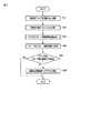
図4は、整合性判定処理の手順を示すフローチャートである。超音波プローブ10が装置本体30に接続される(ステップSa1)。2値化状態発生部19における電気的状態が、プローブIDに変換される(ステップSa2)。変換されたプローブIDは、判定部45に出力される。メモリ23からプローブ識別情報が読み出される(ステップSa3)。読み出されたプローブ識別情報は、判定部45に出力される。プローブIDがプローブ識別情報と照合される(ステップSa4)。プローブIDとプローブ識別情報とが整合すれば(ステップSa5)、超音波の送受信を実行するために、超音波送受信部31が制御される。プローブIDとプローブ識別情報とが不整合であれば(ステップSa5)、超音波送受信部31へのアクセスが停止される(ステップSa6)。このとき、警告出力部47により所定の警告が出力される。 FIG. 4 is a flowchart showing a procedure of consistency determination processing. The
(変形例)
第1の実施形態との相違は、プローブIDとプローブ識別情報とが一覧情報にそれぞれ含まれているか否かを判定することにある。(Modification)
The difference from the first embodiment is that it is determined whether or not the probe ID and the probe identification information are included in the list information.
判定部45は、一覧情報において、プローブIDが含まれているか否かを判定する。以下、一覧情報におけるプローブIDの有無に関する判定結果を、第1判定結果と呼ぶ。判定部45は、一覧情報において、プローブ識別情報が含まれているか否かを判定する。以下、一覧情報におけるプローブ識別情報の有無に関する判定結果を、第2判定結果と呼ぶ。判定部45は、第1判定結果と第2判定結果とを、警告出力部47および制御部49に出力する。また、判定部45は、第1の実施形態における記載と同様に、プローブIDとプローブ識別情報との整合性を判定することができる。 The
具体的には、判定部45は、記憶部37から一覧情報を読み出す。次いで、判定部45は、読み出した一覧情報から、複数のプローブIDを抽出する。判定部45は、抽出した複数のプローブID各々と、プローブ識別子変換部41により変換されたプローブ識別子とを照合する。加えて、判定部45は、抽出した複数のプローブID各々と、読み出されたプローブ識別情報とを照合する。判定部45は、照合結果(第1判定結果、第2判定結果)を、警告出力部47および制御部49に出力する。 Specifically, the
警告出力部47は、第1判定結果と第2判定結果とのうち少なくとも一つが不整合であった場合、所定の警告を出力する。なお、警告出力部47は、所定の警告の出力に応じて、第1、第2判定結果を、インターフェース部39およびネットワークを介して、例えば―サービスマン(所定の操作者)などに送信してもよい。また、プローブ識別情報がメモリ23から消失していた場合、所定の操作者などにより、適宜書き換え、更新されてもよい。 The
具体的には、警告出力部47は、第1判定結果が不整合であって、第2判定結果が整合である場合、所定の警告に関する情報(例えば、HWの断線の可能性、誤挿入(コネクタの向きを逆にして装置本体にコネクタを挿入)など)を、表示部50に出力する。また、警告出力部47は、第1判定結果が整合であって、第2判定結果が不整合である場合、所定の警告に関する情報(例えば、接続された超音波プローブが非正規品である可能性など)を、表示部50に出力する。 Specifically, the
制御部49は、第1、第2判定結果のうち少なくとも一方が不整合であった場合、超音波の送受信を実行しないように、超音波送受信部31を制御する。具体的には、制御部49は、第1、第2判定結果のうち少なくとも一方が不整合であった場合、超音波送受信部31へのアクセスを停止する。第1、第2判定結果がともに整合であった場合、制御部49は、一覧情報におけるプローブIDおよびプローブ識別情報を用いて、装置本体30に接続された超音波プローブ10の種別、特性、駆動方式、スキャン方式、画像処理の方式などを特定する。制御部49は、接続された超音波プローブ10を用いて、特定した種別、特性、駆動方式、スキャン方式などに従って超音波の送受信を実行するために、超音波送受信部31を制御する。また、制御部49は、特定した画像処理の方式に従って、信号処理部33、画像発生部35などを制御する。 The
以上に述べた構成によれば、以下の効果を得ることができる。
本実施形態の超音波診断装置1によれば、超音波プローブ10内に設けられた2値化状態発生部19に記憶された電気的状態を変換したプローブIDと、メモリ23に記憶されたプローブ識別情報との整合性を判定することができる。プローブIDとプローブ識別情報とが不整合であった場合、超音波送受信部31へのアクセスを停止することができる。加えて、エラーメッセージなどの所定の警告を出力することができる。また、表示部50にエラーメッセージなどを表示することができる。また、本実施形態によれば、コネクタ部13と装置本体30との接触不良も検知することが可能となる。すなわち、接触不良が発生すると、プローブIDとプローブ識別情報との整合性を判定することができなくなる。そのため、プローブIDが発生されない場合、またはプローブ識別情報が読み込まれない場合において、コネクタ部13と装置本体30との接触不良を検知することができる。According to the configuration described above, the following effects can be obtained.
According to the ultrasonic
また、本変形例によれば、2値化状態発生部19で発生された電気的状態を変換したプローブIDおよび読み出し部43により読み出されたプローブ識別情報が、記憶部37に記憶された一覧情報に含まれているか否かをそれぞれ判定することができる。 In addition, according to the present modification, a list in which the probe ID obtained by converting the electrical state generated by the
これにより、本変形例によれば、プローブIDが一覧情報に含まれていない場合、HWの断線の可能性、超音波プローブ10を誤った方向で装置本体30に接続する可能性、2値化された電気的状態の改竄の可能性などの所定の警告に関する情報を、表示部50に出力することができる。また、本変形例によれば、プローブIDが一覧情報に含まれ、プローブ識別情報が一覧情報に含まれていない場合、接続された超音波プローブが非正規品である可能性などの所定の警告に関する情報を、表示部50に出力することができる。さらに、第1実施形態と同様に、プローブIDとプローブ識別情報との整合性を判定することもできる。加えて、本変形例によれば、コネクタ部13と装置本体30との接触不良(例えば、HWの断線などによる2値化状態発生部19とプローブ識別子変換部41との接触不良、メモリ23と読み出し部43との接触不良など)を検知することができる。以上のことから、本変形例によれば、一覧情報とプローブIDとの整合性の判定と、一覧情報とプローブ識別情報との整合性の判定とによるダブルチェックが可能となる。 Thereby, according to this modification, when the probe ID is not included in the list information, the possibility of disconnection of the HW, the possibility of connecting the
これらのことから、未保証プローブが本超音波診断装置1の装置本体30に誤って接続された場合において、未保証プローブを誤って認識してしまう問題を解消することができる。これにより、装置本体30に未保証プローブが誤って接続された場合において、適正な超音波プローブの制御および設定などが実施できないことによる本超音波診断装置1の故障、超音波プローブの発熱などによる被検体への危害、および誤診などを招く可能性などを回避することが可能となる。以上のことから、本超音波診断装置1によれば、被検体および超音波診断装置1の安全性の確保することができ、誤診を未然に防ぐことができる。 For these reasons, when an unguaranteed probe is erroneously connected to the apparatus
(第2の実施形態)
第1の実施形態との相違は、メモリ23に記憶されたプローブ識別情報と、外部記憶媒体またはサーバに記憶されたプローブ識別情報リストとの整合性を判定することにある。(Second Embodiment)
The difference from the first embodiment is that the consistency between the probe identification information stored in the
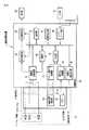
図5は、第2の実施形態に係る超音波診断装置1の構成の一例を示す構成図である。図5に示すように、装置本体30は、暗号解読部44をさらに有する。また、図5に示すように、インターフェース部39には、ネットワークを介してサーバ60が接続される。なお、インターフェース部39には、図5に示すように外部記憶媒体65が接続されてもよい。 FIG. 5 is a configuration diagram illustrating an example of the configuration of the ultrasonic
サーバ60または外部記憶媒体65は、所定の方法で暗号化されたプローブ識別情報リストを記憶する。プローブ識別情報リストとは、異なる複数の超音波プローブ各々に関するプローブ識別情報のリストである。 The
暗号解読部44は、インターフェース部39を介して接続されたサーバ60または外部記憶媒体65から、暗号キーと暗号化されたプローブ識別情報リストとを取得する。暗号解読部44は、暗号キーを用いて、暗号化されたプローブ識別情報リストを解読する。暗号解読部44は、解読したプローブ識別情報リストを、判定部45に出力する。 The
判定部45は、プローブ識別情報とプローブ識別情報リストとの整合性を判定する。判定部45は、整合性の判定結果を後述する警告出力部47と制御部49とに出力する。具体的には、判定部45は、プローブ識別情報をプローブ識別情報リストと照合する。すなわち、判定部45は、プローブ識別情報と、プローブ識別情報リストにおける一つのプローブ識別情報とが一致しているか否かを判定する。 The
(整合性判定機能)
整合性判定機能とは、読み出し部43により読み出されたプローブ識別情報と、暗号解読部44により解読されたプローブ識別情報リストとの整合性を判定する手順に関する機能である。以下、整合性判定機能に関する処理(以下、整合性判定処理と呼ぶ)について説明する。(Consistency judgment function)
The consistency determination function is a function related to a procedure for determining the consistency between the probe identification information read by the
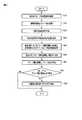
図6は、整合性判定処理の手順を示すフローチャートである。超音波プローブ10が装置本体30に接続される(ステップSb1)。メモリ23からプローブ識別情報が読み出される(ステップSb2)。読み出されたプローブ識別情報は、判定部45に出力される。インターフェース部39を介して、サーバ60に記憶され、暗号キーを使用して、暗号化されたプローブ識別情報リストが解読される(ステップSb3)。なお、ネットワークに接続できない場合、暗号化されたプローブ識別情報リストを記憶した外部記憶媒体65が、インターフェース部39を介して装置本体30に接続されてもよい。解読されたプローブ識別情報リストは、判定部45に出力される。プローブ識別情報がプローブ識別情報リストと照合される(ステップSb4)。プローブ識別情報とプローブ識別情報リストのうち一つのプローブ識別情報とが整合すれば(ステップSb5)、超音波の送受信を実行するために、超音波送受信部31が制御される。プローブ識別情報とプローブ識別情報リストのうち全てのプローブ識別情報とが不整合であれば(ステップSb5)、超音波送受信部31へのアクセスが停止される(ステップSb6)。このとき、警告出力部47により所定の警告が出力されてもよい。 FIG. 6 is a flowchart showing a procedure of consistency determination processing. The
以上に述べた構成によれば、以下の効果を得ることができる。
本実施形態の超音波診断装置1によれば、メモリ23に記憶されたプローブ識別情報と、サーバ60または外部記憶媒体65に記憶されたプローブ識別情報リストとの整合性を判定することができる。プローブ識別情報とプローブ識別情報リストにおける全てのプローブ識別情報とが不整合であった場合、超音波送受信部31へのアクセスを停止することができる。加えて、エラーメッセージなどの所定の警告を出力することができる。また、表示部50にエラーメッセージなどを表示することができる。また、プローブ識別情報リストは、所定の方法により暗号化される。According to the configuration described above, the following effects can be obtained.
According to the ultrasonic
これらのことから、未保証プローブが本超音波診断装置1の装置本体30に誤って接続された場合において、未保証プローブを誤って認識してしまう問題を解消することができる。これにより、装置本体30に未保証プローブが誤って接続された場合において、適正な超音波プローブの制御および設定などが実施できないことによる本超音波診断装置1の故障、超音波プローブの発熱などによる被検体への危害、および誤診などを招く可能性などを回避することが可能となる。以上のことから、本超音波診断装置1によれば、被検体および超音波診断装置1の安全性の確保することができ、誤診を未然に防ぐことができる。また、プローブ識別情報リストは、所定の方法により暗号化されているため、情報漏洩に対する安全性は確保される。 For these reasons, when an unguaranteed probe is erroneously connected to the apparatus
(第3の実施形態)
第1、2の実施形態との相違は、電気的状態に基づいて発生されたプローブIDと、返信信号に対応付けられたプローブ識別情報との整合性を判定することにある。(Third embodiment)
The difference from the first and second embodiments is that the consistency between the probe ID generated based on the electrical state and the probe identification information associated with the return signal is determined.
図7は、第3の実施形態に係る超音波診断装置1の構成の一例を示す構成図である。図7に示すように、コネクタ部13は、返信信号発生部20をさらに有する。装置本体30は、信号送受信部46をさらに有する。 FIG. 7 is a configuration diagram illustrating an example of a configuration of the ultrasonic
信号送受信部46は、超音波プローブ10のコネクタ部13が装置本体30に接続されたとき、後述する返信信号発生部20に送信するための所定の送信信号を発生する。信号送受信部46は、発生した所定の送信信号を送信する。信号送受信部46は、返信信号発生部20から返信された返信信号を受信する。信号送受信部46は、返信信号に対応するプローブ識別情報の対応表を記憶する。信号送受信部46は、返信信号と、対応表とに基づいて、プローブ識別情報を発生する。信号送受信部46は、プローブ識別情報を判定部45に出力する。 The signal transmission /
返信信号発生部20は、所定の送信信号が入力されると、返信信号を発生する。返信信号発生部20は、発生した返信信号を、信号送受信部46に出力する。なお、返信信号発生部20は、入力した所定の送信信号に基づいて、返信信号を発生する図示していない論理回路を有していてもよい。 When a predetermined transmission signal is input, the
判定部45は、プローブ識別子変換部41により変換されたプローブIDとプローブ識別情報との整合性を判定する。判定部45は、整合性の判定結果を後述する警告出力部47と制御部49とに出力する。 The
なお、第3の実施形態に係る超音波診断装置1は、2値化状態発生部19とHW21とプローブ識別子変換部41との代わりに、メモリ23、メモリ接続用ピン29、読み出し部43が設けられてもよい。この時、判定部45は、読み出し部43によりメモリ23から読み出されたプローブ識別情報と、信号送受信部46から出力されたプローブ識別情報との整合性を判定する。 The ultrasonic
(整合性判定機能)
整合性判定機能とは、電気的状態に基づいて発生されたプローブIDと、返信信号に対応付けられたプローブ識別情報との整合性を判定する手順に関する機能である。以下、整合性判定機能に関する処理(以下、整合性判定処理と呼ぶ)について説明する。(Consistency judgment function)
The consistency determination function is a function related to a procedure for determining the consistency between the probe ID generated based on the electrical state and the probe identification information associated with the return signal. Hereinafter, processing related to the consistency determination function (hereinafter referred to as consistency determination processing) will be described.
図8は、整合性判定処理の手順を示すフローチャートである。超音波プローブ10が装置本体30に接続される(ステップSc1)。2値化状態発生部19における電気的状態が、プローブIDに変換される(ステップSc2)。変換されたプローブIDは、判定部45に出力される。所定の送信信号が発生される(ステップSc3)。発生された所定の送信信号は、返信信号発生部20に送信される(ステップSc4)。返信信号と対応表とに基づいて、プローブ識別情報が発生される(ステップSc5)。発生されたプローブ識別情報が、判定部45に出力される(ステップSc6)。プローブ識別情報とプローブIDとが照合される(ステップSc7)。プローブ識別情報とプローブIDとが整合すれば(ステップSc8)、超音波の送受信を実行するために、超音波送受信部31が制御される。プローブ識別情報とプローブIDとが不整合であれば(ステップSc8)、超音波送受信部31へのアクセスが停止される(ステップSc9)。このとき、警告出力部47により所定の警告が出力される。 FIG. 8 is a flowchart showing the procedure of the consistency determination process. The
以上に述べた構成によれば、以下の効果を得ることができる。
本実施形態の超音波診断装置1によれば、超音波プローブ10内に設けられた2値化状態発生部19に記憶された電気的状態を変換したプローブIDと、返信信号と対応表とに基づいて発生されたプローブ識別情報との整合性を判定することができる。プローブIDとプローブ識別情報とが不整合であった場合、超音波送受信部31へのアクセスを停止することができる。加えて、エラーメッセージなどの所定の警告を出力することができる。また、表示部50にエラーメッセージなどを表示することができる。According to the configuration described above, the following effects can be obtained.
According to the ultrasonic
これらのことから、未保証プローブが本超音波診断装置1の装置本体30に誤って接続された場合において、未保証プローブを誤って認識してしまう問題を解消することができる。これにより、装置本体30に未保証プローブが誤って接続された場合において、適正な超音波プローブの制御および設定などが実施できないことによる本超音波診断装置1の故障、超音波プローブの発熱などによる被検体への危害、および誤診などを招く可能性などを回避することが可能となる。以上のことから、本超音波診断装置1によれば、被検体および超音波診断装置1の安全性の確保することができ、誤診を未然に防ぐことができる。 For these reasons, when an unguaranteed probe is erroneously connected to the apparatus
(第4の実施形態)
第1乃至第3の実施形態との相違は、プローブ使用履歴情報に基づいて暗号化されたプローブ識別情報とプローブ使用履歴情報とをメモリ23に記憶し、プローブ使用履歴情報に基づいて暗号化されたプローブ識別情報を解読し、電気的状態に基づいて発生されたプローブIDと解読されたプローブ識別情報との整合性を判定することにある。(Fourth embodiment)
The difference from the first to third embodiments is that the probe identification information and the probe usage history information encrypted based on the probe usage history information are stored in the
図9は、第4の実施形態に係る超音波診断装置1の構成の一例を示す構成図である。図9に示すように、装置本体30は、暗号化書き込み部32と、読み出し解読部34とをさらに有する。 FIG. 9 is a configuration diagram illustrating an example of the configuration of the ultrasonic
暗号化書き込み部32は、プローブの使用履歴情報が更新されると、プローブ使用履歴情報に基づいて、プローブ識別情報を暗号化する。プローブの使用履歴情報は、超音波プローブ10の使用の終了に応じて、制御部49により更新される。暗号化書き込み部32は、暗号化されたプローブ識別情報と、暗号化に用いられたプローブ使用履歴情報とを、メモリ23に書き込む。 When the probe usage history information is updated, the
なお、暗号化書き込み部32は、コネクタ部13に搭載されていてもよい。このとき、暗号化書き込み部32は、コネクタ部13に搭載された図示していない内部電源により、時系列的に変化した暗号を用いてプローブ識別情報を暗号化し、メモリ23に書き込む。また、コネクタ部13が装置本体30に接続されると、暗号化書き込み部32は、時系列的に変化させた暗号の発生に用いられた時系列情報を、読み出し解読部34に出力する。 Note that the
読み出し解読部34は、装置本体30に超音波プローブ10のコネクタ部13が接続されると、暗号化されたプローブ識別情報とプローブ使用履歴情報とをメモリ23から読み出す。読み出し解読部34は、プローブ使用履歴情報を用いて、暗号化されたプローブ識別情報を解読する。読み出し解読部34は、解読したプローブ識別情報を、判定部45に出力する。 When the connector unit 13 of the
なお、コネクタ部13に暗号化書き込み部32が搭載されている場合、読み出し解読部34は、時系列情報に基づいて、暗号化されたプローブ識別情報を解読する。読み出し解読部34は、解読したプローブ識別情報を、判定部45に出力する。 In addition, when the
判定部45は、プローブ識別子変換部41により変換されたプローブIDと解読されたプローブ識別情報との整合性を判定する。判定部45は、整合性の判定結果を警告出力部47と制御部49とに出力する。 The
(整合性判定機能)
整合性判定機能とは、プローブ識別子変換部41により変換されたプローブIDと、解読されたプローブ識別情報との整合性を判定する手順に関する機能である。以下、整合性判定機能に関する処理(以下、整合性判定処理と呼ぶ)について説明する。(Consistency judgment function)
The consistency determination function is a function related to a procedure for determining the consistency between the probe ID converted by the probe
図10は、整合性判定処理の手順を示すフローチャートである。超音波プローブ10が装置本体30に接続される(ステップSd1)。2値化状態発生部19における電気的状態が、プローブIDに変換される(ステップSd2)。変換されたプローブIDは、判定部45に出力される。暗号化されたプローブ識別情報とプローブ使用履歴情報とが、メモリ23から読み出される(ステップSd3)。読み出されたプローブ識別情報が、プローブ使用履歴情報を用いて解読される(ステップSd4)。解読されたプローブ識別情報とプローブIDとが照合される(ステップSd5)。プローブ識別情報とプローブIDとが整合すれば(ステップSd6)、超音波の送受信を実行するために、超音波送受信部31が制御される。超音波プローブ10の使用の終了後、プローブ使用履歴情報が更新される。プローブの使用履歴情報が更新されると、プローブ使用履歴情報に基づいて、プローブ識別情報が暗号化される。暗号化されたプローブ識別情報と、暗号化に用いられたプローブ使用履歴情報とが、メモリ23に書き込まれる。 FIG. 10 is a flowchart illustrating a procedure of consistency determination processing. The
プローブ識別情報とプローブIDとが不整合であれば(ステップSd6)、超音波送受信部31へのアクセスが停止される(ステップSd7)。このとき、警告出力部47により所定の警告が出力される。 If the probe identification information and the probe ID do not match (step Sd6), access to the ultrasonic transmission /
以上に述べた構成によれば、以下の効果を得ることができる。
本実施形態の超音波診断装置1によれば、プローブ使用履歴情報に基づいて暗号化されたプローブ識別情報とプローブ使用履歴情報とをメモリ23に記憶し、プローブ使用履歴情報に基づいて暗号化されたプローブ識別情報を解読し、電気的状態に基づいて発生されたプローブIDと解読されたプローブ識別情報との整合性を判定することができる。プローブIDとプローブ識別情報とが不整合であった場合、超音波送受信部31へのアクセスを停止することができる。加えて、エラーメッセージなどの所定の警告を出力することができる。また、表示部50にエラーメッセージなどを表示することができる。According to the configuration described above, the following effects can be obtained.
According to the ultrasonic
また、本超音波診断装置1は、プローブ識別情報とプローブIDとが整合すれば、超音波プローブ10の使用の終了後、プローブ使用履歴情報を更新し、プローブ使用履歴情報に基づいて、プローブ識別情報を暗号化することができる。次いで、本超音波診断装置1は、暗号化されたプローブ識別情報と、暗号化に用いられたプローブ使用履歴情報とを、メモリ23に書き込むことができる。 In addition, when the probe identification information and the probe ID match, the ultrasonic
これらのことから、未保証プローブが本超音波診断装置1の装置本体30に誤って接続された場合において、未保証プローブを誤って認識してしまう問題を解消することができる。これにより、装置本体30に未保証プローブが誤って接続された場合において、適正な超音波プローブの制御および設定などが実施できないことによる本超音波診断装置1の故障、超音波プローブの発熱などによる被検体への危害、および誤診などを招く可能性などを回避することが可能となる。また、プローブ識別情報はプローブ使用履歴情報を用いて暗号化されてメモリ23に記憶されるため、情報漏洩に対する安全性を確保することができる。以上のことから、本超音波診断装置1によれば、被検体および超音波診断装置1の安全性を確保することができ、誤診を未然に防ぐことができる。 For these reasons, when an unguaranteed probe is erroneously connected to the apparatus
なお、本発明は上記実施形態そのままに限定されるものではなく、実施段階ではその要旨を逸脱しない範囲で構成要素を変形して具体化できる。また、上記実施形態に開示されている複数の構成要素の適宜な組み合わせにより、種々の発明を形成できる。例えば、実施形態に示される全構成要素から幾つかの構成要素を削除してもよい。さらに、異なる実施形態にわたる構成要素を適宜組み合わせてもよい。 Note that the present invention is not limited to the above-described embodiment as it is, and can be embodied by modifying the constituent elements without departing from the scope of the invention in the implementation stage. In addition, various inventions can be formed by appropriately combining a plurality of components disclosed in the embodiment. For example, some components may be deleted from all the components shown in the embodiment. Furthermore, constituent elements over different embodiments may be appropriately combined.
1…超音波診断装置、10…超音波プローブ、11…プローブ本体、13…コネクタ部、15…ケーブル、17…信号用ピン、19…2値化状態発生部、20…返信信号発生部、21…ハードワイヤ(HW)、23…メモリ、25…2値化電気的状態発生部、27…暗号化部、29…メモリ接続用ピン、30…装置本体、31…超音波送受信部、32…暗号化書き込み部、33…信号処理部、34…読み出し解読部、35…画像発生部、37…記憶部、39…インターフェース部、41…プローブ識別子変換部、43…読み出し部、44…暗号解読部、45…判定部、46…信号送受信部、47…警告出力部、49…制御部、50…表示部、60…サーバ、65…外部記憶媒体、70…入力部 DESCRIPTION OF
Claims (4)
Translated fromJapanese前記電気的状態を前記プローブ識別子に変換するプローブ識別子変換部と、
前記メモリから前記プローブ識別情報を読み出す読み出し部と、
前記変換されたプローブ識別子と前記読み出されたプローブ識別情報との整合性を判定する判定部と、
前記判定部による判定結果において前記プローブ識別子と前記プローブ識別情報とが不整合である場合、所定の警告を出力する警告出力部と、
を具備し、
前記メモリは、プローブ使用履歴情報と前記プローブ使用履歴情報に基づいて暗号化されたプローブ識別情報とをさらに記憶し、
前記メモリから前記プローブ識別情報を読み出し、前記プローブ使用履歴情報に基づいて前記プローブ識別情報を解読する読み出し解読部をさらに具備し、
前記判定部は、
前記変換されたプローブ識別子と前記解読されたプローブ識別情報との整合性を判定し、
前記警告出力部は、
前記判定部による判定結果において前記プローブ識別子と前記解読されたプローブ識別情報とが不整合である場合、前記所定の警告を出力する超音波診断装置。An ultrasonic probe having a plurality of transducers, a memory that stores probe identification information, and a binarized state generating unit that generates a binarized electrical state corresponding to the probe identifier;
A probe identifier converter for converting the electrical state into the probe identifier;
A reading unit for reading the probe identification information from the memory;
A determination unit for determining consistency between the converted probe identifier and the read probe identification information;
If the probe identifier and the probe identification information are inconsistent in the determination result by the determination unit, a warning output unit that outputs a predetermined warning;
Comprising
The memory further stores probe usage history information and probe identification information encrypted based on the probe usage history information,
Read the probe identification information from the memory, further comprising a read decoding unit for decoding the probe identification information based on the probe usage history information,
The determination unit
Determining consistency between the converted probe identifier and the decoded probe identification information;
The warning output unit
The ultrasonic diagnostic apparatus that outputs the predetermined warning when the probe identifier and the decoded probe identification information are inconsistent in the determination result by the determination unit.
前記複数の振動子にそれぞれ接続される複数の配線を有するケーブルと、
前記ケーブルの端部に設けられ、超音波診断装置本体に接続されるコネクタ部とを具備し、
前記コネクタ部は、
前記プローブ本体に関するプローブ識別子に対応する2値化された電気的状態を発生する2値化状態発生部と、
前記プローブ本体に関するプローブ識別情報を記憶するメモリとを有し、
前記プローブ本体の使用履歴情報に基づいて前記プローブ識別情報を暗号化する暗号化部をさらに具備し、
前記メモリは、前記使用履歴情報と前記暗号化されたプローブ識別情報とを記憶する超音波プローブ。A probe body having a plurality of transducers;
A cable having a plurality of wires respectively connected to the plurality of vibrators;
Provided at the end of the cable, comprising a connector portion connected to the ultrasonic diagnostic apparatus body,
The connector part is
A binarized state generator for generating a binarized electrical state corresponding to a probe identifier related to the probe body;
A memory for storing probe identification information related to the probe body,
Further comprising an encryption unit for encrypting the probe identification information based on the usage history information of the probe body;
The memory is an ultrasonic probe that stores the usage history information and the encrypted probe identification information.
前記暗号化部は、前記コネクタ部に設けられ、時系列情報を用いて、前記プローブ識別
情報を暗号化する請求項3に記載の超音波プローブ。The connector part comprises an internal power supply,
The ultrasonic probe according to claim3 , wherein the encryption unit is provided in the connector unit and encrypts the probe identification information using time series information.
Priority Applications (4)
| Application Number | Priority Date | Filing Date | Title |
|---|---|---|---|
| JP2013126815AJP6257930B2 (en) | 2012-08-07 | 2013-06-17 | Ultrasonic diagnostic apparatus and ultrasonic probe |
| PCT/JP2013/067246WO2014024588A1 (en) | 2012-08-07 | 2013-06-24 | Ultrasound diagnostic device and ultrasound probe |
| CN201380000769.7ACN103747741B (en) | 2012-08-07 | 2013-06-24 | Ultrasonic diagnostic device and ultrasonic probe |
| US14/189,187US10390794B2 (en) | 2012-08-07 | 2014-02-25 | Ultrasound diagnostic apparatus and ultrasound probe |
Applications Claiming Priority (3)
| Application Number | Priority Date | Filing Date | Title |
|---|---|---|---|
| JP2012175203 | 2012-08-07 | ||
| JP2012175203 | 2012-08-07 | ||
| JP2013126815AJP6257930B2 (en) | 2012-08-07 | 2013-06-17 | Ultrasonic diagnostic apparatus and ultrasonic probe |
Publications (2)
| Publication Number | Publication Date |
|---|---|
| JP2014050674A JP2014050674A (en) | 2014-03-20 |
| JP6257930B2true JP6257930B2 (en) | 2018-01-10 |
Family
ID=50067829
Family Applications (1)
| Application Number | Title | Priority Date | Filing Date |
|---|---|---|---|
| JP2013126815AActiveJP6257930B2 (en) | 2012-08-07 | 2013-06-17 | Ultrasonic diagnostic apparatus and ultrasonic probe |
Country Status (4)
| Country | Link |
|---|---|
| US (1) | US10390794B2 (en) |
| JP (1) | JP6257930B2 (en) |
| CN (1) | CN103747741B (en) |
| WO (1) | WO2014024588A1 (en) |
Cited By (1)
| Publication number | Priority date | Publication date | Assignee | Title |
|---|---|---|---|---|
| JP3029657B2 (en) | 1990-09-28 | 2000-04-04 | カヤバ工業株式会社 | Position detection device |
Families Citing this family (145)
| Publication number | Priority date | Publication date | Assignee | Title |
|---|---|---|---|---|
| US11871901B2 (en) | 2012-05-20 | 2024-01-16 | Cilag Gmbh International | Method for situational awareness for surgical network or surgical network connected device capable of adjusting function based on a sensed situation or usage |
| US9901324B2 (en)* | 2013-09-03 | 2018-02-27 | Samsung Electronics Co., Ltd. | Ultrasound probe and method of operating the same |
| CN105249992A (en)* | 2014-02-20 | 2016-01-20 | 飞依诺科技(苏州)有限公司 | RF-data-based ultrasonic imaging processing method and system |
| US11504192B2 (en) | 2014-10-30 | 2022-11-22 | Cilag Gmbh International | Method of hub communication with surgical instrument systems |
| KR102518468B1 (en) | 2015-10-16 | 2023-04-05 | 삼성전자주식회사 | Probe apparatus, medical instrument and controlling method thereof |
| WO2017081566A1 (en)* | 2015-11-11 | 2017-05-18 | Koninklijke Philips N.V. | Systems and methods for associating and verifying an association of a transducer with an imaging device |
| WO2018006348A1 (en)* | 2016-07-07 | 2018-01-11 | 深圳企管加企业服务有限公司 | Method and system for response based on ultrasonic wave |
| FR3053597B1 (en)* | 2016-07-08 | 2025-08-22 | Carthera | METHOD AND SYSTEM FOR DETECTING AN ELECTRICAL CONNECTION FAULT BETWEEN AN ULTRASONIC DEVICE AND A REMOTE CONTROL UNIT |
| EP3366221A1 (en)* | 2017-02-28 | 2018-08-29 | Koninklijke Philips N.V. | An intelligent ultrasound system |
| JP6491698B2 (en)* | 2017-06-23 | 2019-03-27 | 株式会社ミツトヨ | Three-dimensional measurement unit and measuring probe identification method |
| CN111183333A (en)* | 2017-10-02 | 2020-05-19 | 海克斯康测量技术有限公司 | Coordinate measuring machine probe identification apparatus and method |
| US11229436B2 (en) | 2017-10-30 | 2022-01-25 | Cilag Gmbh International | Surgical system comprising a surgical tool and a surgical hub |
| US11510741B2 (en) | 2017-10-30 | 2022-11-29 | Cilag Gmbh International | Method for producing a surgical instrument comprising a smart electrical system |
| US11801098B2 (en) | 2017-10-30 | 2023-10-31 | Cilag Gmbh International | Method of hub communication with surgical instrument systems |
| US11311342B2 (en) | 2017-10-30 | 2022-04-26 | Cilag Gmbh International | Method for communicating with surgical instrument systems |
| US11317919B2 (en) | 2017-10-30 | 2022-05-03 | Cilag Gmbh International | Clip applier comprising a clip crimping system |
| US11911045B2 (en) | 2017-10-30 | 2024-02-27 | Cllag GmbH International | Method for operating a powered articulating multi-clip applier |
| US11291510B2 (en) | 2017-10-30 | 2022-04-05 | Cilag Gmbh International | Method of hub communication with surgical instrument systems |
| US11564756B2 (en) | 2017-10-30 | 2023-01-31 | Cilag Gmbh International | Method of hub communication with surgical instrument systems |
| US11026687B2 (en) | 2017-10-30 | 2021-06-08 | Cilag Gmbh International | Clip applier comprising clip advancing systems |
| US11925373B2 (en) | 2017-10-30 | 2024-03-12 | Cilag Gmbh International | Surgical suturing instrument comprising a non-circular needle |
| CN107647904B (en)* | 2017-11-06 | 2020-12-04 | 上海联影医疗科技股份有限公司 | Puncture needle detection method, device and system |
| US12376855B2 (en) | 2017-12-28 | 2025-08-05 | Cilag Gmbh International | Safety systems for smart powered surgical stapling |
| US11818052B2 (en) | 2017-12-28 | 2023-11-14 | Cilag Gmbh International | Surgical network determination of prioritization of communication, interaction, or processing based on system or device needs |
| US11389164B2 (en) | 2017-12-28 | 2022-07-19 | Cilag Gmbh International | Method of using reinforced flexible circuits with multiple sensors to optimize performance of radio frequency devices |
| US11559308B2 (en) | 2017-12-28 | 2023-01-24 | Cilag Gmbh International | Method for smart energy device infrastructure |
| US11026751B2 (en) | 2017-12-28 | 2021-06-08 | Cilag Gmbh International | Display of alignment of staple cartridge to prior linear staple line |
| US20190201112A1 (en) | 2017-12-28 | 2019-07-04 | Ethicon Llc | Computer implemented interactive surgical systems |
| US11013563B2 (en) | 2017-12-28 | 2021-05-25 | Ethicon Llc | Drive arrangements for robot-assisted surgical platforms |
| US11308075B2 (en) | 2017-12-28 | 2022-04-19 | Cilag Gmbh International | Surgical network, instrument, and cloud responses based on validation of received dataset and authentication of its source and integrity |
| US11273001B2 (en) | 2017-12-28 | 2022-03-15 | Cilag Gmbh International | Surgical hub and modular device response adjustment based on situational awareness |
| US11304763B2 (en) | 2017-12-28 | 2022-04-19 | Cilag Gmbh International | Image capturing of the areas outside the abdomen to improve placement and control of a surgical device in use |
| US10918310B2 (en) | 2018-01-03 | 2021-02-16 | Biosense Webster (Israel) Ltd. | Fast anatomical mapping (FAM) using volume filling |
| US11786245B2 (en) | 2017-12-28 | 2023-10-17 | Cilag Gmbh International | Surgical systems with prioritized data transmission capabilities |
| US11179175B2 (en) | 2017-12-28 | 2021-11-23 | Cilag Gmbh International | Controlling an ultrasonic surgical instrument according to tissue location |
| US11696760B2 (en) | 2017-12-28 | 2023-07-11 | Cilag Gmbh International | Safety systems for smart powered surgical stapling |
| US10892899B2 (en) | 2017-12-28 | 2021-01-12 | Ethicon Llc | Self describing data packets generated at an issuing instrument |
| US11464535B2 (en) | 2017-12-28 | 2022-10-11 | Cilag Gmbh International | Detection of end effector emersion in liquid |
| US10943454B2 (en) | 2017-12-28 | 2021-03-09 | Ethicon Llc | Detection and escalation of security responses of surgical instruments to increasing severity threats |
| US11234756B2 (en) | 2017-12-28 | 2022-02-01 | Cilag Gmbh International | Powered surgical tool with predefined adjustable control algorithm for controlling end effector parameter |
| US11202570B2 (en) | 2017-12-28 | 2021-12-21 | Cilag Gmbh International | Communication hub and storage device for storing parameters and status of a surgical device to be shared with cloud based analytics systems |
| US11633237B2 (en) | 2017-12-28 | 2023-04-25 | Cilag Gmbh International | Usage and technique analysis of surgeon / staff performance against a baseline to optimize device utilization and performance for both current and future procedures |
| US11056244B2 (en) | 2017-12-28 | 2021-07-06 | Cilag Gmbh International | Automated data scaling, alignment, and organizing based on predefined parameters within surgical networks |
| US11076921B2 (en) | 2017-12-28 | 2021-08-03 | Cilag Gmbh International | Adaptive control program updates for surgical hubs |
| US10966791B2 (en) | 2017-12-28 | 2021-04-06 | Ethicon Llc | Cloud-based medical analytics for medical facility segmented individualization of instrument function |
| US11659023B2 (en) | 2017-12-28 | 2023-05-23 | Cilag Gmbh International | Method of hub communication |
| US20190201142A1 (en) | 2017-12-28 | 2019-07-04 | Ethicon Llc | Automatic tool adjustments for robot-assisted surgical platforms |
| US10892995B2 (en) | 2017-12-28 | 2021-01-12 | Ethicon Llc | Surgical network determination of prioritization of communication, interaction, or processing based on system or device needs |
| US11304745B2 (en) | 2017-12-28 | 2022-04-19 | Cilag Gmbh International | Surgical evacuation sensing and display |
| US11571234B2 (en) | 2017-12-28 | 2023-02-07 | Cilag Gmbh International | Temperature control of ultrasonic end effector and control system therefor |
| US11291495B2 (en) | 2017-12-28 | 2022-04-05 | Cilag Gmbh International | Interruption of energy due to inadvertent capacitive coupling |
| US11786251B2 (en) | 2017-12-28 | 2023-10-17 | Cilag Gmbh International | Method for adaptive control schemes for surgical network control and interaction |
| US11304699B2 (en) | 2017-12-28 | 2022-04-19 | Cilag Gmbh International | Method for adaptive control schemes for surgical network control and interaction |
| US11051876B2 (en) | 2017-12-28 | 2021-07-06 | Cilag Gmbh International | Surgical evacuation flow paths |
| US11464559B2 (en) | 2017-12-28 | 2022-10-11 | Cilag Gmbh International | Estimating state of ultrasonic end effector and control system therefor |
| US20190206569A1 (en) | 2017-12-28 | 2019-07-04 | Ethicon Llc | Method of cloud based data analytics for use with the hub |
| US11903601B2 (en) | 2017-12-28 | 2024-02-20 | Cilag Gmbh International | Surgical instrument comprising a plurality of drive systems |
| US11529187B2 (en) | 2017-12-28 | 2022-12-20 | Cilag Gmbh International | Surgical evacuation sensor arrangements |
| US11602393B2 (en) | 2017-12-28 | 2023-03-14 | Cilag Gmbh International | Surgical evacuation sensing and generator control |
| US11324557B2 (en) | 2017-12-28 | 2022-05-10 | Cilag Gmbh International | Surgical instrument with a sensing array |
| US11832899B2 (en) | 2017-12-28 | 2023-12-05 | Cilag Gmbh International | Surgical systems with autonomously adjustable control programs |
| US20190201090A1 (en) | 2017-12-28 | 2019-07-04 | Ethicon Llc | Capacitive coupled return path pad with separable array elements |
| US11540855B2 (en) | 2017-12-28 | 2023-01-03 | Cilag Gmbh International | Controlling activation of an ultrasonic surgical instrument according to the presence of tissue |
| US12396806B2 (en) | 2017-12-28 | 2025-08-26 | Cilag Gmbh International | Adjustment of a surgical device function based on situational awareness |
| WO2019133144A1 (en) | 2017-12-28 | 2019-07-04 | Ethicon Llc | Detection and escalation of security responses of surgical instruments to increasing severity threats |
| US11832840B2 (en) | 2017-12-28 | 2023-12-05 | Cilag Gmbh International | Surgical instrument having a flexible circuit |
| US10849697B2 (en) | 2017-12-28 | 2020-12-01 | Ethicon Llc | Cloud interface for coupled surgical devices |
| US12127729B2 (en) | 2017-12-28 | 2024-10-29 | Cilag Gmbh International | Method for smoke evacuation for surgical hub |
| US11666331B2 (en) | 2017-12-28 | 2023-06-06 | Cilag Gmbh International | Systems for detecting proximity of surgical end effector to cancerous tissue |
| US10944728B2 (en) | 2017-12-28 | 2021-03-09 | Ethicon Llc | Interactive surgical systems with encrypted communication capabilities |
| US11069012B2 (en)* | 2017-12-28 | 2021-07-20 | Cilag Gmbh International | Interactive surgical systems with condition handling of devices and data capabilities |
| US11896322B2 (en) | 2017-12-28 | 2024-02-13 | Cilag Gmbh International | Sensing the patient position and contact utilizing the mono-polar return pad electrode to provide situational awareness to the hub |
| US11364075B2 (en) | 2017-12-28 | 2022-06-21 | Cilag Gmbh International | Radio frequency energy device for delivering combined electrical signals |
| US11132462B2 (en) | 2017-12-28 | 2021-09-28 | Cilag Gmbh International | Data stripping method to interrogate patient records and create anonymized record |
| US12062442B2 (en) | 2017-12-28 | 2024-08-13 | Cilag Gmbh International | Method for operating surgical instrument systems |
| US11419630B2 (en) | 2017-12-28 | 2022-08-23 | Cilag Gmbh International | Surgical system distributed processing |
| US11266468B2 (en) | 2017-12-28 | 2022-03-08 | Cilag Gmbh International | Cooperative utilization of data derived from secondary sources by intelligent surgical hubs |
| US12096916B2 (en) | 2017-12-28 | 2024-09-24 | Cilag Gmbh International | Method of sensing particulate from smoke evacuated from a patient, adjusting the pump speed based on the sensed information, and communicating the functional parameters of the system to the hub |
| US11424027B2 (en) | 2017-12-28 | 2022-08-23 | Cilag Gmbh International | Method for operating surgical instrument systems |
| US10987178B2 (en) | 2017-12-28 | 2021-04-27 | Ethicon Llc | Surgical hub control arrangements |
| US11937769B2 (en) | 2017-12-28 | 2024-03-26 | Cilag Gmbh International | Method of hub communication, processing, storage and display |
| US11166772B2 (en) | 2017-12-28 | 2021-11-09 | Cilag Gmbh International | Surgical hub coordination of control and communication of operating room devices |
| US11284936B2 (en) | 2017-12-28 | 2022-03-29 | Cilag Gmbh International | Surgical instrument having a flexible electrode |
| US11998193B2 (en) | 2017-12-28 | 2024-06-04 | Cilag Gmbh International | Method for usage of the shroud as an aspect of sensing or controlling a powered surgical device, and a control algorithm to adjust its default operation |
| US11744604B2 (en) | 2017-12-28 | 2023-09-05 | Cilag Gmbh International | Surgical instrument with a hardware-only control circuit |
| US20190201039A1 (en) | 2017-12-28 | 2019-07-04 | Ethicon Llc | Situational awareness of electrosurgical systems |
| US11559307B2 (en) | 2017-12-28 | 2023-01-24 | Cilag Gmbh International | Method of robotic hub communication, detection, and control |
| US11147607B2 (en) | 2017-12-28 | 2021-10-19 | Cilag Gmbh International | Bipolar combination device that automatically adjusts pressure based on energy modality |
| US10932872B2 (en) | 2017-12-28 | 2021-03-02 | Ethicon Llc | Cloud-based medical analytics for linking of local usage trends with the resource acquisition behaviors of larger data set |
| US11969216B2 (en) | 2017-12-28 | 2024-04-30 | Cilag Gmbh International | Surgical network recommendations from real time analysis of procedure variables against a baseline highlighting differences from the optimal solution |
| US11317937B2 (en) | 2018-03-08 | 2022-05-03 | Cilag Gmbh International | Determining the state of an ultrasonic end effector |
| US11576677B2 (en) | 2017-12-28 | 2023-02-14 | Cilag Gmbh International | Method of hub communication, processing, display, and cloud analytics |
| US11096693B2 (en) | 2017-12-28 | 2021-08-24 | Cilag Gmbh International | Adjustment of staple height of at least one row of staples based on the sensed tissue thickness or force in closing |
| US11100631B2 (en) | 2017-12-28 | 2021-08-24 | Cilag Gmbh International | Use of laser light and red-green-blue coloration to determine properties of back scattered light |
| US11857152B2 (en) | 2017-12-28 | 2024-01-02 | Cilag Gmbh International | Surgical hub spatial awareness to determine devices in operating theater |
| US11896443B2 (en) | 2017-12-28 | 2024-02-13 | Cilag Gmbh International | Control of a surgical system through a surgical barrier |
| US11423007B2 (en) | 2017-12-28 | 2022-08-23 | Cilag Gmbh International | Adjustment of device control programs based on stratified contextual data in addition to the data |
| US11589888B2 (en) | 2017-12-28 | 2023-02-28 | Cilag Gmbh International | Method for controlling smart energy devices |
| US11419667B2 (en) | 2017-12-28 | 2022-08-23 | Cilag Gmbh International | Ultrasonic energy device which varies pressure applied by clamp arm to provide threshold control pressure at a cut progression location |
| US11410259B2 (en) | 2017-12-28 | 2022-08-09 | Cilag Gmbh International | Adaptive control program updates for surgical devices |
| US11678881B2 (en) | 2017-12-28 | 2023-06-20 | Cilag Gmbh International | Spatial awareness of surgical hubs in operating rooms |
| US11160605B2 (en) | 2017-12-28 | 2021-11-02 | Cilag Gmbh International | Surgical evacuation sensing and motor control |
| US11278281B2 (en) | 2017-12-28 | 2022-03-22 | Cilag Gmbh International | Interactive surgical system |
| US11612444B2 (en) | 2017-12-28 | 2023-03-28 | Cilag Gmbh International | Adjustment of a surgical device function based on situational awareness |
| US11179208B2 (en) | 2017-12-28 | 2021-11-23 | Cilag Gmbh International | Cloud-based medical analytics for security and authentication trends and reactive measures |
| US10898622B2 (en) | 2017-12-28 | 2021-01-26 | Ethicon Llc | Surgical evacuation system with a communication circuit for communication between a filter and a smoke evacuation device |
| US11446052B2 (en) | 2017-12-28 | 2022-09-20 | Cilag Gmbh International | Variation of radio frequency and ultrasonic power level in cooperation with varying clamp arm pressure to achieve predefined heat flux or power applied to tissue |
| US11257589B2 (en) | 2017-12-28 | 2022-02-22 | Cilag Gmbh International | Real-time analysis of comprehensive cost of all instrumentation used in surgery utilizing data fluidity to track instruments through stocking and in-house processes |
| US11304720B2 (en) | 2017-12-28 | 2022-04-19 | Cilag Gmbh International | Activation of energy devices |
| US11109866B2 (en) | 2017-12-28 | 2021-09-07 | Cilag Gmbh International | Method for circular stapler control algorithm adjustment based on situational awareness |
| US11969142B2 (en) | 2017-12-28 | 2024-04-30 | Cilag Gmbh International | Method of compressing tissue within a stapling device and simultaneously displaying the location of the tissue within the jaws |
| US11432885B2 (en) | 2017-12-28 | 2022-09-06 | Cilag Gmbh International | Sensing arrangements for robot-assisted surgical platforms |
| US11311306B2 (en) | 2017-12-28 | 2022-04-26 | Cilag Gmbh International | Surgical systems for detecting end effector tissue distribution irregularities |
| US11376002B2 (en) | 2017-12-28 | 2022-07-05 | Cilag Gmbh International | Surgical instrument cartridge sensor assemblies |
| US11864728B2 (en) | 2017-12-28 | 2024-01-09 | Cilag Gmbh International | Characterization of tissue irregularities through the use of mono-chromatic light refractivity |
| US10758310B2 (en) | 2017-12-28 | 2020-09-01 | Ethicon Llc | Wireless pairing of a surgical device with another device within a sterile surgical field based on the usage and situational awareness of devices |
| US11253315B2 (en) | 2017-12-28 | 2022-02-22 | Cilag Gmbh International | Increasing radio frequency to create pad-less monopolar loop |
| US11986233B2 (en) | 2018-03-08 | 2024-05-21 | Cilag Gmbh International | Adjustment of complex impedance to compensate for lost power in an articulating ultrasonic device |
| US11534196B2 (en) | 2018-03-08 | 2022-12-27 | Cilag Gmbh International | Using spectroscopy to determine device use state in combo instrument |
| US12303159B2 (en) | 2018-03-08 | 2025-05-20 | Cilag Gmbh International | Methods for estimating and controlling state of ultrasonic end effector |
| US11259830B2 (en) | 2018-03-08 | 2022-03-01 | Cilag Gmbh International | Methods for controlling temperature in ultrasonic device |
| US11471156B2 (en) | 2018-03-28 | 2022-10-18 | Cilag Gmbh International | Surgical stapling devices with improved rotary driven closure systems |
| US11219453B2 (en) | 2018-03-28 | 2022-01-11 | Cilag Gmbh International | Surgical stapling devices with cartridge compatible closure and firing lockout arrangements |
| US11096688B2 (en) | 2018-03-28 | 2021-08-24 | Cilag Gmbh International | Rotary driven firing members with different anvil and channel engagement features |
| US11207067B2 (en) | 2018-03-28 | 2021-12-28 | Cilag Gmbh International | Surgical stapling device with separate rotary driven closure and firing systems and firing member that engages both jaws while firing |
| US11090047B2 (en) | 2018-03-28 | 2021-08-17 | Cilag Gmbh International | Surgical instrument comprising an adaptive control system |
| US11589865B2 (en) | 2018-03-28 | 2023-02-28 | Cilag Gmbh International | Methods for controlling a powered surgical stapler that has separate rotary closure and firing systems |
| US11278280B2 (en) | 2018-03-28 | 2022-03-22 | Cilag Gmbh International | Surgical instrument comprising a jaw closure lockout |
| US11213294B2 (en) | 2018-03-28 | 2022-01-04 | Cilag Gmbh International | Surgical instrument comprising co-operating lockout features |
| US10973520B2 (en) | 2018-03-28 | 2021-04-13 | Ethicon Llc | Surgical staple cartridge with firing member driven camming assembly that has an onboard tissue cutting feature |
| US11399799B2 (en)* | 2018-04-20 | 2022-08-02 | Canon Medical Systems Corporation | Ultrasound diagnostic apparatus and ultrasound probe |
| CN111329513A (en)* | 2018-12-18 | 2020-06-26 | 无锡触典科技有限公司 | Ultrasonic voltage matching method and system |
| US11464511B2 (en) | 2019-02-19 | 2022-10-11 | Cilag Gmbh International | Surgical staple cartridges with movable authentication key arrangements |
| US11317915B2 (en) | 2019-02-19 | 2022-05-03 | Cilag Gmbh International | Universal cartridge based key feature that unlocks multiple lockout arrangements in different surgical staplers |
| US11369377B2 (en) | 2019-02-19 | 2022-06-28 | Cilag Gmbh International | Surgical stapling assembly with cartridge based retainer configured to unlock a firing lockout |
| US11357503B2 (en) | 2019-02-19 | 2022-06-14 | Cilag Gmbh International | Staple cartridge retainers with frangible retention features and methods of using same |
| US11331100B2 (en) | 2019-02-19 | 2022-05-17 | Cilag Gmbh International | Staple cartridge retainer system with authentication keys |
| JP7105207B2 (en)* | 2019-03-22 | 2022-07-22 | 富士フイルムヘルスケア株式会社 | Ultrasonic probe, ultrasonic diagnostic apparatus, and method for manufacturing ultrasonic probe |
| USD952144S1 (en) | 2019-06-25 | 2022-05-17 | Cilag Gmbh International | Surgical staple cartridge retainer with firing system authentication key |
| USD964564S1 (en) | 2019-06-25 | 2022-09-20 | Cilag Gmbh International | Surgical staple cartridge retainer with a closure system authentication key |
| USD950728S1 (en) | 2019-06-25 | 2022-05-03 | Cilag Gmbh International | Surgical staple cartridge |
| CN110279937A (en)* | 2019-07-11 | 2019-09-27 | 合肥芯福传感器技术有限公司 | Self-identifying combined multifunctional therapeutic probe |
| FR3107651B1 (en) | 2020-03-02 | 2022-03-11 | Carthera | METHOD AND SYSTEM FOR DETECTING AN ACOUSTIC COUPLING DEFECT BETWEEN AN ULTRASOUND DEVICE AND A TISSUE TO BE TREATED |
| KR20210119173A (en)* | 2020-03-24 | 2021-10-05 | 삼성메디슨 주식회사 | Ultrasonic probe, ultrasonic imaging device and controlling method thereof |
| JP7686538B2 (en)* | 2021-11-08 | 2025-06-02 | キヤノンメディカルシステムズ株式会社 | Conversion adapter and ultrasonic diagnostic device |
Family Cites Families (15)
| Publication number | Priority date | Publication date | Assignee | Title |
|---|---|---|---|---|
| JPH07391A (en)* | 1993-04-22 | 1995-01-06 | Toshiba Corp | Ultrasonic diagnostic equipment |
| JP3967429B2 (en)* | 1997-08-29 | 2007-08-29 | 株式会社東芝 | Ultrasonic diagnostic equipment |
| CA2286107C (en) | 1998-02-10 | 2007-01-09 | Biosense, Inc. | Improved catheter calibration |
| JPH11299781A (en) | 1998-04-24 | 1999-11-02 | Toshiba Corp | Ultrasonic diagnostic device adapter and ultrasonic diagnostic device |
| JP2002000602A (en)* | 2000-06-20 | 2002-01-08 | Matsushita Electric Ind Co Ltd | Ultrasound diagnostic equipment |
| JP4632527B2 (en)* | 2000-12-08 | 2011-02-16 | 株式会社東芝 | Ultrasonic probe and ultrasonic diagnostic apparatus |
| GB2380037B (en)* | 2001-05-10 | 2005-03-02 | Jump To It Ltd | Recognition system |
| JP4076736B2 (en)* | 2001-05-25 | 2008-04-16 | ペンタックス株式会社 | Endoscope device |
| JP4342859B2 (en)* | 2002-09-30 | 2009-10-14 | 富士フイルム株式会社 | Ultrasonic probe and ultrasonic transmitter / receiver using the same |
| US20040171935A1 (en)* | 2004-03-12 | 2004-09-02 | Siemens Medical Solutions Usa, Inc. | Ultrasound transducer probe identification for security and other purposes |
| EP1815796A4 (en)* | 2004-11-17 | 2009-10-28 | Hitachi Medical Corp | ULTRASONIC UNIT AND METHOD FOR DISPLAYING AN ULTRASOUND IMAGE |
| US8033174B2 (en)* | 2007-09-07 | 2011-10-11 | Medison Co. Ltd. | Ultrasound diagnostic system |
| JP2010069178A (en)* | 2008-09-22 | 2010-04-02 | Fujifilm Corp | Medical image diagnostic apparatus and medical image diagnostic system |
| US20100305442A1 (en)* | 2009-05-29 | 2010-12-02 | Boston Scientific Scimed, Inc. | Systems and methods for implementing a data management system for catheter-based imaging systems |
| CN202355709U (en)* | 2011-10-28 | 2012-08-01 | 深圳市威尔德医疗电子有限公司 | Ultrasonic probe with recognition function and ultrasonic therapeutic device |
- 2013
- 2013-06-17JPJP2013126815Apatent/JP6257930B2/enactiveActive
- 2013-06-24CNCN201380000769.7Apatent/CN103747741B/enactiveActive
- 2013-06-24WOPCT/JP2013/067246patent/WO2014024588A1/ennot_activeCeased
- 2014
- 2014-02-25USUS14/189,187patent/US10390794B2/enactiveActive
Cited By (1)
| Publication number | Priority date | Publication date | Assignee | Title |
|---|---|---|---|---|
| JP3029657B2 (en) | 1990-09-28 | 2000-04-04 | カヤバ工業株式会社 | Position detection device |
Also Published As
| Publication number | Publication date |
|---|---|
| CN103747741B (en) | 2015-11-25 |
| WO2014024588A1 (en) | 2014-02-13 |
| CN103747741A (en) | 2014-04-23 |
| JP2014050674A (en) | 2014-03-20 |
| US10390794B2 (en) | 2019-08-27 |
| US20140171802A1 (en) | 2014-06-19 |
Similar Documents
| Publication | Publication Date | Title |
|---|---|---|
| JP6257930B2 (en) | Ultrasonic diagnostic apparatus and ultrasonic probe | |
| US9119558B2 (en) | Ultrasonic diagnostic apparatus and ultrasonic diagnostic method | |
| JP5461845B2 (en) | Ultrasonic diagnostic apparatus and control program for ultrasonic diagnostic apparatus | |
| JP6342164B2 (en) | Ultrasonic diagnostic equipment | |
| CN103211614B (en) | Ultrasonic diagnostic apparatus, phase shift transmission/reception control method, and ultrasonic probe | |
| CN111655154B (en) | Ultrasound imaging method and ultrasound imaging system | |
| JP2015211726A (en) | Ultrasonic diagnostic apparatus and ultrasonic probe | |
| JP7309355B2 (en) | Medical image generation device and medical image generation program | |
| US20160066888A1 (en) | Ultrasonic diagnostic apparatus and image processing apparatus | |
| JP2016073452A (en) | Ultrasonic diagnostic equipment | |
| JP2023160986A (en) | Ultrasonic diagnostic device and analysis device | |
| CN102365054A (en) | Ultrasonic diagnostic device and ultrasonic image processing device | |
| JP6457054B2 (en) | Ultrasonic diagnostic equipment | |
| WO2014133094A1 (en) | Ultrasound diagnostic device | |
| CN113229847B (en) | Image processing device, ultrasonic diagnostic device, and computer program product | |
| JP5366429B2 (en) | Ultrasonic diagnostic apparatus and ultrasonic diagnostic apparatus control program | |
| CN107427288A (en) | Acoustic image generation device and method | |
| JP6780976B2 (en) | Ultrasonic diagnostic equipment | |
| JP5823184B2 (en) | Ultrasonic diagnostic apparatus, medical image processing apparatus, and medical image processing program | |
| JP2013099386A (en) | Ultrasonic diagnostic apparatus and medical image processing apparatus | |
| JP2015054061A (en) | Ultrasonic diagnostic apparatus, medical image processing apparatus, and medical image processing program | |
| JP5060141B2 (en) | Ultrasonic diagnostic equipment | |
| JP5773642B2 (en) | Ultrasonic diagnostic apparatus, medical image processing method, and medical image processing program | |
| JP2015062570A (en) | Ultrasonic diagnostic equipment, medical image processor, and medical image processing program | |
| JP4966226B2 (en) | Ultrasonic image processing apparatus and method, and program |
Legal Events
| Date | Code | Title | Description |
|---|---|---|---|
| RD04 | Notification of resignation of power of attorney | Free format text:JAPANESE INTERMEDIATE CODE: A7424 Effective date:20131219 | |
| RD04 | Notification of resignation of power of attorney | Free format text:JAPANESE INTERMEDIATE CODE: A7424 Effective date:20131226 | |
| RD04 | Notification of resignation of power of attorney | Free format text:JAPANESE INTERMEDIATE CODE: A7424 Effective date:20140109 | |
| A711 | Notification of change in applicant | Free format text:JAPANESE INTERMEDIATE CODE: A711 Effective date:20160512 | |
| A621 | Written request for application examination | Free format text:JAPANESE INTERMEDIATE CODE: A621 Effective date:20160524 | |
| A131 | Notification of reasons for refusal | Free format text:JAPANESE INTERMEDIATE CODE: A131 Effective date:20161115 | |
| A521 | Request for written amendment filed | Free format text:JAPANESE INTERMEDIATE CODE: A523 Effective date:20170112 | |
| A02 | Decision of refusal | Free format text:JAPANESE INTERMEDIATE CODE: A02 Effective date:20170613 | |
| A521 | Request for written amendment filed | Free format text:JAPANESE INTERMEDIATE CODE: A523 Effective date:20170908 | |
| A911 | Transfer to examiner for re-examination before appeal (zenchi) | Free format text:JAPANESE INTERMEDIATE CODE: A911 Effective date:20170927 | |
| TRDD | Decision of grant or rejection written | ||
| A01 | Written decision to grant a patent or to grant a registration (utility model) | Free format text:JAPANESE INTERMEDIATE CODE: A01 Effective date:20171107 | |
| A61 | First payment of annual fees (during grant procedure) | Free format text:JAPANESE INTERMEDIATE CODE: A61 Effective date:20171206 | |
| R150 | Certificate of patent or registration of utility model | Ref document number:6257930 Country of ref document:JP Free format text:JAPANESE INTERMEDIATE CODE: R150 | |
| S533 | Written request for registration of change of name | Free format text:JAPANESE INTERMEDIATE CODE: R313533 | |
| R350 | Written notification of registration of transfer | Free format text:JAPANESE INTERMEDIATE CODE: R350 |