JP6257132B2 - Light guide device - Google Patents
Light guide deviceDownload PDFInfo
- Publication number
- JP6257132B2 JP6257132B2JP2012227635AJP2012227635AJP6257132B2JP 6257132 B2JP6257132 B2JP 6257132B2JP 2012227635 AJP2012227635 AJP 2012227635AJP 2012227635 AJP2012227635 AJP 2012227635AJP 6257132 B2JP6257132 B2JP 6257132B2
- Authority
- JP
- Japan
- Prior art keywords
- light
- ring
- light guide
- shaped portion
- receiving surface
- Prior art date
- Legal status (The legal status is an assumption and is not a legal conclusion. Google has not performed a legal analysis and makes no representation as to the accuracy of the status listed.)
- Expired - Fee Related
Links
Images


Classifications
- G—PHYSICS
- G02—OPTICS
- G02B—OPTICAL ELEMENTS, SYSTEMS OR APPARATUS
- G02B6/00—Light guides; Structural details of arrangements comprising light guides and other optical elements, e.g. couplings
- G02B6/0001—Light guides; Structural details of arrangements comprising light guides and other optical elements, e.g. couplings specially adapted for lighting devices or systems
- G02B6/0011—Light guides; Structural details of arrangements comprising light guides and other optical elements, e.g. couplings specially adapted for lighting devices or systems the light guides being planar or of plate-like form
- G02B6/0013—Means for improving the coupling-in of light from the light source into the light guide
- G02B6/0015—Means for improving the coupling-in of light from the light source into the light guide provided on the surface of the light guide or in the bulk of it
- G02B6/002—Means for improving the coupling-in of light from the light source into the light guide provided on the surface of the light guide or in the bulk of it by shaping at least a portion of the light guide, e.g. with collimating, focussing or diverging surfaces
- B—PERFORMING OPERATIONS; TRANSPORTING
- B60—VEHICLES IN GENERAL
- B60N—SEATS SPECIALLY ADAPTED FOR VEHICLES; VEHICLE PASSENGER ACCOMMODATION NOT OTHERWISE PROVIDED FOR
- B60N3/00—Arrangements or adaptations of other passenger fittings, not otherwise provided for
- B60N3/10—Arrangements or adaptations of other passenger fittings, not otherwise provided for of receptacles for food or beverages, e.g. refrigerated
- B—PERFORMING OPERATIONS; TRANSPORTING
- B60—VEHICLES IN GENERAL
- B60K—ARRANGEMENT OR MOUNTING OF PROPULSION UNITS OR OF TRANSMISSIONS IN VEHICLES; ARRANGEMENT OR MOUNTING OF PLURAL DIVERSE PRIME-MOVERS IN VEHICLES; AUXILIARY DRIVES FOR VEHICLES; INSTRUMENTATION OR DASHBOARDS FOR VEHICLES; ARRANGEMENTS IN CONNECTION WITH COOLING, AIR INTAKE, GAS EXHAUST OR FUEL SUPPLY OF PROPULSION UNITS IN VEHICLES
- B60K35/00—Instruments specially adapted for vehicles; Arrangement of instruments in or on vehicles
- B60K35/60—Instruments characterised by their location or relative disposition in or on vehicles
- B—PERFORMING OPERATIONS; TRANSPORTING
- B60—VEHICLES IN GENERAL
- B60Q—ARRANGEMENT OF SIGNALLING OR LIGHTING DEVICES, THE MOUNTING OR SUPPORTING THEREOF OR CIRCUITS THEREFOR, FOR VEHICLES IN GENERAL
- B60Q3/00—Arrangement of lighting devices for vehicle interiors; Lighting devices specially adapted for vehicle interiors
- B60Q3/20—Arrangement of lighting devices for vehicle interiors; Lighting devices specially adapted for vehicle interiors for lighting specific fittings of passenger or driving compartments; mounted on specific fittings of passenger or driving compartments
- B60Q3/225—Small compartments, e.g. glove compartments
- B60Q3/229—Cup holders
- B—PERFORMING OPERATIONS; TRANSPORTING
- B60—VEHICLES IN GENERAL
- B60Q—ARRANGEMENT OF SIGNALLING OR LIGHTING DEVICES, THE MOUNTING OR SUPPORTING THEREOF OR CIRCUITS THEREFOR, FOR VEHICLES IN GENERAL
- B60Q3/00—Arrangement of lighting devices for vehicle interiors; Lighting devices specially adapted for vehicle interiors
- B60Q3/40—Arrangement of lighting devices for vehicle interiors; Lighting devices specially adapted for vehicle interiors specially adapted for specific vehicle types
- B60Q3/41—Arrangement of lighting devices for vehicle interiors; Lighting devices specially adapted for vehicle interiors specially adapted for specific vehicle types for mass transit vehicles, e.g. buses
- B60Q3/43—General lighting
- B—PERFORMING OPERATIONS; TRANSPORTING
- B60—VEHICLES IN GENERAL
- B60Q—ARRANGEMENT OF SIGNALLING OR LIGHTING DEVICES, THE MOUNTING OR SUPPORTING THEREOF OR CIRCUITS THEREFOR, FOR VEHICLES IN GENERAL
- B60Q3/00—Arrangement of lighting devices for vehicle interiors; Lighting devices specially adapted for vehicle interiors
- B60Q3/60—Arrangement of lighting devices for vehicle interiors; Lighting devices specially adapted for vehicle interiors characterised by optical aspects
- B60Q3/62—Arrangement of lighting devices for vehicle interiors; Lighting devices specially adapted for vehicle interiors characterised by optical aspects using light guides
- B60Q3/64—Arrangement of lighting devices for vehicle interiors; Lighting devices specially adapted for vehicle interiors characterised by optical aspects using light guides for a single lighting device
- G—PHYSICS
- G02—OPTICS
- G02B—OPTICAL ELEMENTS, SYSTEMS OR APPARATUS
- G02B6/00—Light guides; Structural details of arrangements comprising light guides and other optical elements, e.g. couplings
- G02B6/0001—Light guides; Structural details of arrangements comprising light guides and other optical elements, e.g. couplings specially adapted for lighting devices or systems
- G02B6/0005—Light guides; Structural details of arrangements comprising light guides and other optical elements, e.g. couplings specially adapted for lighting devices or systems the light guides being of the fibre type
- G02B6/001—Light guides; Structural details of arrangements comprising light guides and other optical elements, e.g. couplings specially adapted for lighting devices or systems the light guides being of the fibre type the light being emitted along at least a portion of the lateral surface of the fibre
- G—PHYSICS
- G02—OPTICS
- G02B—OPTICAL ELEMENTS, SYSTEMS OR APPARATUS
- G02B6/00—Light guides; Structural details of arrangements comprising light guides and other optical elements, e.g. couplings
- G02B6/0001—Light guides; Structural details of arrangements comprising light guides and other optical elements, e.g. couplings specially adapted for lighting devices or systems
- G02B6/0011—Light guides; Structural details of arrangements comprising light guides and other optical elements, e.g. couplings specially adapted for lighting devices or systems the light guides being planar or of plate-like form
- G02B6/0033—Means for improving the coupling-out of light from the light guide
- G02B6/0035—Means for improving the coupling-out of light from the light guide provided on the surface of the light guide or in the bulk of it
- G02B6/0045—Means for improving the coupling-out of light from the light guide provided on the surface of the light guide or in the bulk of it by shaping at least a portion of the light guide
- B—PERFORMING OPERATIONS; TRANSPORTING
- B60—VEHICLES IN GENERAL
- B60K—ARRANGEMENT OR MOUNTING OF PROPULSION UNITS OR OF TRANSMISSIONS IN VEHICLES; ARRANGEMENT OR MOUNTING OF PLURAL DIVERSE PRIME-MOVERS IN VEHICLES; AUXILIARY DRIVES FOR VEHICLES; INSTRUMENTATION OR DASHBOARDS FOR VEHICLES; ARRANGEMENTS IN CONNECTION WITH COOLING, AIR INTAKE, GAS EXHAUST OR FUEL SUPPLY OF PROPULSION UNITS IN VEHICLES
- B60K2360/00—Indexing scheme associated with groups B60K35/00 or B60K37/00 relating to details of instruments or dashboards
- B60K2360/20—Optical features of instruments
- B60K2360/33—Illumination features
- B60K2360/336—Light guides
- B—PERFORMING OPERATIONS; TRANSPORTING
- B60—VEHICLES IN GENERAL
- B60K—ARRANGEMENT OR MOUNTING OF PROPULSION UNITS OR OF TRANSMISSIONS IN VEHICLES; ARRANGEMENT OR MOUNTING OF PLURAL DIVERSE PRIME-MOVERS IN VEHICLES; AUXILIARY DRIVES FOR VEHICLES; INSTRUMENTATION OR DASHBOARDS FOR VEHICLES; ARRANGEMENTS IN CONNECTION WITH COOLING, AIR INTAKE, GAS EXHAUST OR FUEL SUPPLY OF PROPULSION UNITS IN VEHICLES
- B60K2360/00—Indexing scheme associated with groups B60K35/00 or B60K37/00 relating to details of instruments or dashboards
- B60K2360/20—Optical features of instruments
- B60K2360/33—Illumination features
- B60K2360/341—Illumination of dials
Landscapes
- Engineering & Computer Science (AREA)
- Physics & Mathematics (AREA)
- Mechanical Engineering (AREA)
- General Physics & Mathematics (AREA)
- Optics & Photonics (AREA)
- Transportation (AREA)
- Thermal Sciences (AREA)
- Chemical & Material Sciences (AREA)
- Combustion & Propulsion (AREA)
- Planar Illumination Modules (AREA)
- Arrangements Of Lighting Devices For Vehicle Interiors, Mounting And Supporting Thereof, Circuits Therefore (AREA)
- Non-Portable Lighting Devices Or Systems Thereof (AREA)
- Light Guides In General And Applications Therefor (AREA)
Description
Translated fromJapanese本発明は、導光体装置に関する。 The present invention relates to a light guide device.
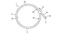
特許文献1は、図8、図9に示すように、単一の光源2と、導光体3と、を有する導光体装置1を開示している。導光体3は、周方向に全周にわたって連続して延びるリング状部3aと、受光面3bから導光体3内に導入される光をリング状部3aにリング状部3aの周方向の一方向Dからのみ進入させる外周側延び部3cと、備える。Patent document 1 is disclosing the light guide apparatus 1 which has the
リング状部3aに一方向Dから進入した光は、リング状部3aとリング状部3aの外周側にある大気との境界面5で全反射されて、リング状部3a内を一方向Dに進む。また、リング状部3aに進入した光は、リング状部3の内周面3dに施される表面処理によって拡散される。よって、リング状部3aがリング状に発光する。The light that has entered the ring-
しかし、従来の導光体装置1には、つぎの問題点がある。
リング状部3aに一方向Dから進入した光は、反射と拡散を繰り返すたびに減衰する。そのため、外周側延び部3cから遠くなるに従いリング状部3aの輝度が低くなる。そのため、図9に示すように、外周側延び部3cに近い部位3eと遠い部位3fとで大きな輝度差が生じてしまう。また、リング状部3aが周方向に全周にわたって連続して延びるリング状であるため、外周側延び部3cに近い部位3eと遠い部位3fとが隣り合わせになり、外周側延び部3cに近い部位3dと遠い部位3eとの輝度差が顕著に表れてしまい、外観が悪くなる。However, the conventional light guide device 1 has the following problems.
The light that has entered the ring-
本発明の目的は、従来に比べて、リング状部の輝度を全周にわたって均一に近づけることができる、導光体装置を提供することにある。 An object of the present invention is to provide a light guide device capable of bringing the brightness of a ring-shaped portion closer to uniform over the entire circumference as compared with the prior art.
上記目的を達成する本発明はつぎの通りである。
(1) 〔実施例1,2〕
光源と、導光体と、光反射機構と、を有しており、
前記光源は、1つのみ設けられており、
前記導光体は、周方向に全周にわたって連続して延びるリング状部と、前記光源からの光を前記導光体内に導入する受光面と、前記リング状部から該リング状部の外周側に延びて設けられており前記受光面から前記導光体内に導入される光を前記リング状部に該リング状部の周方向の一方向から進入させる外周側延び部と、を備えており、
前記光反射機構は、1つのみ設けられており、前記受光面から前記導光体内に導入される光の一部を反射させて、前記リング状部に該リング状部の周方向の前記一方向と反対の方向から進入させており、
前記リング状部は円形であり、前記光源は前記リング状部の周上から外れた位置に設けられており、
前記外周側延び部は、前記受光面から前記導光体内に導入される光を、前記リング状部に該リング状部の周方向の一方向から該リング状部の接線方向に進入させており、該接線上に前記光反射機構は設けられている、
導光体装置。
(2) 〔実施例1,2〕
前記光反射機構は、前記外周側延び部に設けられ屈折率が前記導光体の屈折率とは異なる層部と、前記導光体と前記層部との境界面と、を備えており、該境界面で前記受光面から前記導光体内に導入される光の一部を反射させる、(1)記載の導光体装置。
(3) 〔実施例1,2〕
前記層部の媒質は空気である、(2)記載の導光体装置。
(4) 〔実施例1〕
前記境界面は、前記受光面から前記導光体内に導入されて前記境界面に進む光の全部を反射させる、(2)または(3)記載の導光体装置。
(5) 〔実施例2〕
前記境界面は、前記受光面から前記導光体内に導入されて前記境界面に進む光の、一部を反射させ、残りを屈折させて前記層部内に進入させる、(2)または(3)記載の導光体装置。The present invention for achieving the above object is as follows.
(1) [Examples 1 and 2]
A light source, a light guide, and a light reflection mechanism;
Only one light source is provided,
The light guide includes a ring-shaped portion that continuously extends in the circumferential direction, a light receiving surface that introduces light from the light source into the light guide, and an outer peripheral side of the ring-shaped portion from the ring-shaped portion. An outer peripheral side extending portion that allows light introduced into the light guide from the light receiving surface to enter the ring-shaped portion from one circumferential direction of the ring-shaped portion, and
Only one light reflecting mechanism isprovided, and a part of light introduced into the light guide body from the light receiving surface is reflected so that the ring-shaped portion has the one in the circumferential direction of the ring-shaped portion. It is approaching from the opposite direction,
The ring-shaped part is circular, and the light source is provided at a position off the circumference of the ring-shaped part,
The outer peripheral extending portion allows light introduced from the light receiving surface into the light guide body to enter the ring-shaped portion from one direction in the circumferential direction of the ring-shaped portion in a tangential direction of the ring-shaped portion. The light reflecting mechanism is provided on the tangent line.
Light guide device.
(2) [Examples 1 and 2]
The light reflecting mechanism includes a layer portion provided in the outer peripheral extending portion and having a refractive index different from the refractive index of the light guide, and a boundary surface between the light guide and the layer portion, The light guide device according to (1), wherein a part of light introduced into the light guide from the light receiving surface is reflected from the boundary surface.
(3) [Examples 1 and 2]
The light guide device according to (2), wherein the medium of the layer portion is air.
(4) [Example 1]
The light guide device according to (2) or (3), wherein the boundary surface reflects all of the light that is introduced from the light receiving surface into the light guide and travels to the boundary surface.
(5) [Example 2]
The boundary surface reflects a part of the light introduced from the light receiving surface into the light guide and travels to the boundary surface, and refracts the remaining light to enter the layer portion. (2) or (3) The light guide device described.
上記(1)の導光体装置によれば、光反射機構が設けられているため、受光面から導光体内に導入される光を、リング状部に、リング状部の周方向の両方向から進入させることができる。そのため、光反射機構が設けられていない場合(従来)に比べて、リング状部の輝度を全周にわたって均一に近づけることができる。According to the light guide device of (1) above, since the light reflecting mechanism is provided, the light introduced into the light guide from the light receiving surface is transmitted to the ring-shaped portion from both circumferential directions of the ring-shaped portion. Can enter. Therefore, the brightness of the ring-shaped portion can be made uniform over the entire circumference as compared with the case where no light reflection mechanism is provided (conventional).
上記(2)の導光体装置によれば、光反射機構が、外周側延び部に設けられる層部と、導光体と層部との境界面と、を備えているため、光反射機構はリング状部ではなく外周側延び部に設けられる。そのため、光反射機構がリング状部に設けられる場合に比べて、光反射機構によるリング状部の輝度ムラが生じにくくなり、リング状部の輝度を全周にわたって均一に近づけることができる。 According to the light guide device of (2) above, the light reflection mechanism includes the layer portion provided in the outer peripheral extending portion and the boundary surface between the light guide and the layer portion. Is provided not on the ring-shaped part but on the outer peripheral side extending part. Therefore, as compared with the case where the light reflecting mechanism is provided in the ring-shaped portion, unevenness in the brightness of the ring-shaped portion due to the light reflecting mechanism is less likely to occur, and the luminance of the ring-shaped portion can be made to approach uniformly over the entire circumference.
上記(3)の導光体装置によれば、層部の媒質が空気であるため、層部の媒質が空気以外である場合に比べて、コスト上有利である。According to the light guide device of (3) above, since the medium of the layer portion is air, it is advantageous in terms of cost compared to the case where the medium of the layer portion is other than air.
上記(4)の導光体装置によれば、境界面が、受光面から導光体内に導入されて境界面に進む光の全部を反射させる場合であっても、上記(2)で得られる効果を得ることができる。According to the light guide device of (4) above, even when the boundary surface reflects all of the light that is introduced from the light receiving surface into the light guide body and travels to the boundary surface, it can be obtained by (2) above. An effect can be obtained.
上記(5)の導光体装置によれば、境界面が、受光面から導光体内に導入されて境界面に進む光の、一部を反射させ、残りを屈折させて層部内に進入させる場合であっても、上記(2)で得られる効果を得ることができる。 According to the light guide device of (5) above, the boundary surface reflects a part of the light that is introduced from the light receiving surface into the light guide and travels to the boundary surface, and refracts the remaining light to enter the layer portion. Even if it is a case, the effect acquired by said (2) can be acquired.
図1〜図4は、本発明実施例1の導光体装置を示しており、図5〜図7は、本発明実施例2の導光体装置を示している。
本発明実施例1と実施例2にわたって共通する部分には、本発明実施例1と実施例2にわたって同じ符号を付してある。
まず、本発明実施例1と実施例2にわたって共通する部分を、説明する。1 to 4 show the light guide device of the first embodiment of the present invention, and FIGS. 5 to 7 show the light guide device of the second embodiment of the present invention.
Portions common to the first and second embodiments of the present invention are denoted by the same reference numerals throughout the first and second embodiments of the present invention.
First, parts common to the first and second embodiments of the present invention will be described.
本発明実施例の導光体装置10は、たとえば、車両用カップホルダのリング状照明に用いられる。ただし、導光体装置10は、スピーカーグリル、レジスターグリルなどのリング状の車両の内装部品に用いられていてもよい。また、導光体装置10は、車両用コンソールボックス等の車両用ボックスに設けられていてもよい。
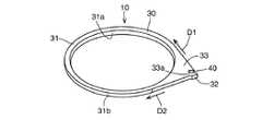
導光体装置10は、図1に示すように、光源20と、導光体30と、光反射機構40と、を有する。The
As illustrated in FIG. 1, the
光源20は、1つのみ設けられる。光源20は、たとえば、LED(発光ダイオード)、バルブ等からなる。中でもLEDを用いることが望ましい。この理由は、LEDは小型であり装置10の小型化を図る点で有利であるからである。また、発熱量が小さく、周囲の部材(導光体30等)への熱の影響を少なくできるからである。 Only one
導光体30は、たとえば、光透過性材料で構成されている。光透過性材料は、たとえば、ポリカーボネート、アクリル樹脂などである。導光体30は、一平面内に設けられている。導光体30は、部品点数の削減のために一部品構成とされていることが望ましい。導光体30は、型成形品である。
導光体30は、リング状部31と、受光面32と、外周側延び部33と、を備える。The
The
リング状部31は、1つのみ設けられる。リング状部31は、周方向に全周にわたって連続して延びている。リング状部31は、平面視で、円形であってもよく、楕円形であってもよく、長円形であってもよく、その他の形状であってもよい。リング状部31の断面形状は、たとえば矩形である。リング状部31の内周面31aには、リング状部31内の光を拡散させるために、シボ加工等の表面処理が施されている。Only one ring-shaped
リング状部31に進入した光は、リング状部31とリング状部31の外周側にある大気との境界面31bで全反射されて、リング状部31内をリング状部31の周方向に進む。また、リング状部31に進入した光は、リング状部31の内周面31aに施される表面処理によって拡散される。よって、リング状部31の内周面31aが全周にわたってリング状に発光する。The light that has entered the ring-shaped
受光面32は、光源20からの光を導光体30内に導入するために設けられている。受光面32は、受光面32によってリング状部31の輝度ムラが生じることを抑制するために、外周側延び部33に設けられている。受光面32は、外周側延び部33の、リング状部31から最も離れた部分に設けられていることが望ましい。受光面32は、1つのみ設けられる。受光面32は、光源20に対向する位置にある。受光面32は、光源20の熱の影響を受けることを抑制するために、光源20から離れて配置されている。受光面32は、平面であってもよく、凸湾曲面であってもよく、凹湾曲面であってもよい。The
外周側延び部33は、リング状部31の周方向一部から、リング状部31の外周側に延びて(突出して)設けられている。外周側延び部33の平面視形状は、略二等辺三角形であり、リング状部31から最も離れた位置にある角の角度は90度〜102度の範囲内にあることが望ましい。その角の角度が90度より小さい場合、外周側延び部33の形状が大きく(長く)なり材料コストが高くなるからである。ただし、当該角度の範囲は導光体30の光透過性材料がポリカーボネートの例であり、アクリル樹脂など異なる屈折率を持つ光透過性材料の場合、それぞれ望ましい角度は異なる。
外周側延び部33は、1つのみ設けられる。外周側延び部33は、受光面32から導光体30内に導入される光を、リング状部31に、リング状部31の周方向の一方向D1から進入させる。The outer peripheral
Only one outer peripheral extending
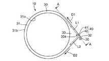
光反射機構40は、図3に示すように、受光面32から導光体30内に導入される光の一部のみ(全部ではない)を反射させて、リング状部31に、リング状部31の周方向の一方向D1と反対の方向D2から進入させる。光反射機構40により、受光面32から導光体30内に導入される光の少なくとも一部は、リング状部31に一方向D1から進入する光L1と、リング状部31に反対方向D2から進入する光L2とに分けられる。なお、リング状部31が平面視で円形である場合、光L1と光L2はその円の接線方向と同方向となるように設定されている。
光反射機構40は、受光面32から導光体30内に導入される光の一部を、リング状部31に進入する前に反射させる。光反射機構40は、層部41と、境界面42と、を備える。As shown in FIG. 3, the
The
層部41は、外周側延び部33に設けられている。層部41は、1つのみ設けられる。層部41の屈折率は、導光体30の屈折率とは異なっている。層部41の屈折率は、境界面42で全反射を生じさせるために、導光体30の屈折率より小さい。層部41の媒質は、特に限定されるものではないが、たとえば空気である。層部41は、図4に示すように、外周側延び部33の一部に外周側延び部33の外面から凹む凹部(切欠き形状部)33aを設けることで形成される。The
境界面42は、外周側延び部33と層部41との境界のうち、受光面32に対向する位置にある面である。境界面42は、平面であってもよく、湾曲面であってもよい。図3に示すように、受光面32から導光体30内に導入される光の一部が、境界面42で反射される。受光面32から導光体30内に導入されて境界面42に進む光のうち、入射角(境界面42の垂線と境界面42に進む光の進行方向とがなす角)が臨界角を超える光のみが、層部41内に進入することなく境界面42で反射される。部品点数削減によるコストダウンを図るために、境界面42には、光を反射させるためのフィルム等の部材は一切設けられていない。The
境界面42は、受光面32から導光体30内に導入されて境界面42に進む光の全部を反射させていてもよい(実施例1)。また、境界面42は、受光面32から導光体30内に導入されて境界面42に進む光の、一部のみを反射させ、残りを屈折させて層部41内に進入させていてもよい(実施例2)。The
つぎに、本発明実施例1と実施例2にわたって共通する作用を説明する。
光源20から放出された光は、受光面32から導光体30内に導入される。導光体30内に導入された光は、外周側延び部33を通ってリング状部31に一方向D1から進入しようとする。しかし、装置10には光反射機構40が設けられているため、リング状部31に一方向D1から進入しようとする光の一部を、反射させて、リング状部31に一方向D1と反対の方向D2から進入する光L2にすることができる。そのため、受光面32から導光体30内に導入される光を、リング状部31に一方向D1から進入する光L1と、リング状部31に反対方向D2から進入する光L2とに分けることができる(2分できる)。そのため、光反射機構が設けられていない場合(従来)に比べて、リング状部の輝度を全周にわたって均一に近づけることができる。Next, an operation common to the first and second embodiments of the present invention will be described.
The light emitted from the
光反射機構40が、外周側延び部33に設けられる層部41と、導光体30と層部41との境界面42と、を備えているため、光反射機構40はリング状部31ではなく外周側延び部33に設けられる。そのため、光反射機構40がリング状部31に設けられる場合に比べて、光反射機構40によるリング状部31の輝度ムラが生じにくくなり、リング状部31の輝度を全周にわたって均一に近づけることができる。 Since the
層部41の媒質が空気であるため、層部41の媒質が空気以外である場合に比べて、コスト上有利である。Since the medium of the
つぎに、本発明各実施例に特有な部分を説明する。
〔実施例1〕(図1〜図4)
本発明実施例1では、境界面42が、受光面32から導光体30内に導入されて境界面42に進む光の全部を反射させる場合を示している。Next, parts unique to each embodiment of the present invention will be described.
[Example 1] (FIGS. 1 to 4)
The first embodiment of the present invention shows a case where the
境界面42は、図4に示すように、外周側延び部33の厚み方向(外周側延び部33内を進む光の進行方向と直交する方向、リング状部31の軸方向)の一部のみに設けられている。すなわち、層部41と、層部41を形成するための凹部33とは、外周側延び部33の厚み方向の一部のみに設けられている。 As shown in FIG. 4, the
本発明実施例1の作用を説明する。
(a)受光面32から導光体30内に導入されて境界面42に進む光は、図3に示すように、境界面42で反射されて、リング状部31に一方向D1と反対の方向D2から進入する光L2になる。また、(b)受光面32から導光体30内に導入される光のうち境界面42に進まない光は、そのままリング状部31に一方向D1から進入する光L1になる。
よって、境界面42が、受光面32から導光体30内に導入されて境界面42に進む光の全部を反射させる場合であっても、受光面32から導光体30内に導入される光を、光L1と光L2とに分けることができる(2分できる)。The operation of the first embodiment of the present invention will be described.
(A) Light that is introduced from the
Therefore, even when the
境界面42(層部41、凹部33)を外周側延び部33の厚み方向の半分に設けることにより、光L1の量と光L2の量とを等しくすることができる。そのため、リング状部31の輝度を全周にわたってより均一に近づけることができる。 By providing the boundary surface 42 (the
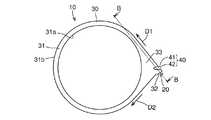
〔実施例2〕(図5〜図7)
本発明実施例2では、図7に示すように、境界面42が、受光面32から導光体30内に導入されて境界面42に進む光の、一部のみを反射させ、残りを屈折させて層部41内に進入させる場合を示している。[Example 2] (FIGS. 5 to 7)
In
境界面42は、図6に示すように、外周側延び部33の厚み方向(外周側延び部33内を進む光の進行方向と直交する方向、リング状部31の軸方向)の全体にわたって設けられている。すなわち、層部41と、層部41を形成するための凹部33とは、外周側延び部33の厚み方向の全体にわたって設けられている。 As shown in FIG. 6, the
本発明実施例2の作用を説明する。
(a)受光面32から導光体30内に導入されて境界面42に進む光の一部は、入射角が臨界角より大となっている。そのため、図7に示すように、境界面42で全反射されてリング状部31に一方向D1と反対の方向D2から進入する光になる。また、(b)受光面32から導光体30内に導入されて境界面42に進む光の残りは、入射角が臨界角より小となっている。そのため、境界面42で屈折されて層部41内に進入する。層部41に進入した光は、層部41内を進んだ後、境界面42とは異なる第2の境界面50で屈折されて再び外周側延び部33内に進入し、リング状部31に一方向D1から進入する光L1となる。
よって、境界面42が、受光面32から導光体30内に導入されて境界面42に進む光の、一部を反射させ、残りを屈折させて層部41内に進入させる場合であっても、受光面32から導光体30内に導入される光を、光L1と光L2とに分けることができる(2分できる)。The operation of
(A) The incident angle of a part of the light introduced from the
Therefore, the
境界面42の角度を、境界面42の面積の半分に進む光を反射させ、境界面42の面積の残り半分に進む光を屈折させて層部41内に進入させる角度にすることで、光L1の量と光L2の量とを等しくすることができる。そのため、リング状部31の輝度を全周にわたってより均一に近づけることができる。By making the angle of the
10 導光体装置
20 光源
30 導光体
31 リング状部
32 受光面
33 外周側延び部
33a 凹部
40 光反射機構
41 層部
42 境界面
D1 リング状部の周方向の一方向
D2 リング状部の周方向の一方向と反対の方向
L1、L2 光DESCRIPTION OF
Claims (5)
Translated fromJapanese前記光源は、1つのみ設けられており、
前記導光体は、周方向に全周にわたって連続して延びるリング状部と、前記光源からの光を前記導光体内に導入する受光面と、前記リング状部から該リング状部の外周側に延びて設けられており前記受光面から前記導光体内に導入される光を前記リング状部に該リング状部の周方向の一方向から進入させる外周側延び部と、を備えており、
前記光反射機構は、1つのみ設けられており、前記受光面から前記導光体内に導入される光の一部を反射させて、前記リング状部に該リング状部の周方向の前記一方向と反対の方向から進入させており、
前記リング状部は円形であり、前記光源は前記リング状部の周上から外れた位置に設けられており、
前記外周側延び部は、前記受光面から前記導光体内に導入される光を、前記リング状部に該リング状部の周方向の一方向から該リング状部の接線方向に進入させており、該接線上に前記光反射機構は設けられている、
導光体装置。A light source, a light guide, and a light reflection mechanism;
Only one light source is provided,
The light guide includes a ring-shaped portion that continuously extends in the circumferential direction, a light receiving surface that introduces light from the light source into the light guide, and an outer peripheral side of the ring-shaped portion from the ring-shaped portion. An outer peripheral side extending portion that allows light introduced into the light guide from the light receiving surface to enter the ring-shaped portion from one circumferential direction of the ring-shaped portion, and
Only one light reflecting mechanism isprovided, and a part of light introduced into the light guide body from the light receiving surface is reflected so that the ring-shaped portion has the one in the circumferential direction of the ring-shaped portion. It is approaching from the opposite direction,
The ring-shaped part is circular, and the light source is provided at a position off the circumference of the ring-shaped part,
The outer peripheral extending portion allows light introduced from the light receiving surface into the light guide body to enter the ring-shaped portion from one direction in the circumferential direction of the ring-shaped portion in a tangential direction of the ring-shaped portion. The light reflecting mechanism is provided on the tangent line.
Light guide device.
The boundary surface reflects a part of light introduced from the light receiving surface into the light guide and travels to the boundary surface, and refracts the remaining light to enter the layer portion. The light guide device described.
Priority Applications (4)
| Application Number | Priority Date | Filing Date | Title |
|---|---|---|---|
| JP2012227635AJP6257132B2 (en) | 2012-10-15 | 2012-10-15 | Light guide device |
| PCT/JP2013/077572WO2014061541A1 (en) | 2012-10-15 | 2013-10-10 | Light guide apparatus |
| CN201380053439.4ACN104704287B (en) | 2012-10-15 | 2013-10-10 | Light conductor device |
| US14/435,215US9618676B2 (en) | 2012-10-15 | 2013-10-10 | Ring-shaped light-conducting apparatus with uniform luminance |
Applications Claiming Priority (1)
| Application Number | Priority Date | Filing Date | Title |
|---|---|---|---|
| JP2012227635AJP6257132B2 (en) | 2012-10-15 | 2012-10-15 | Light guide device |
Publications (2)
| Publication Number | Publication Date |
|---|---|
| JP2014082032A JP2014082032A (en) | 2014-05-08 |
| JP6257132B2true JP6257132B2 (en) | 2018-01-10 |
Family
ID=50488108
Family Applications (1)
| Application Number | Title | Priority Date | Filing Date |
|---|---|---|---|
| JP2012227635AExpired - Fee RelatedJP6257132B2 (en) | 2012-10-15 | 2012-10-15 | Light guide device |
Country Status (4)
| Country | Link |
|---|---|
| US (1) | US9618676B2 (en) |
| JP (1) | JP6257132B2 (en) |
| CN (1) | CN104704287B (en) |
| WO (1) | WO2014061541A1 (en) |
Families Citing this family (12)
| Publication number | Priority date | Publication date | Assignee | Title |
|---|---|---|---|---|
| TWI563203B (en)* | 2013-09-18 | 2016-12-21 | Nifco Inc | Illumination device |
| TWI507746B (en)* | 2014-02-07 | 2015-11-11 | E Ink Holdings Inc | Light guide module |
| JP6398519B2 (en)* | 2014-09-19 | 2018-10-03 | カシオ計算機株式会社 | Ring illumination device and clock |
| CN107531178B (en)* | 2015-05-28 | 2020-08-25 | 株式会社利富高 | lighting device |
| JP6521371B2 (en)* | 2015-05-29 | 2019-05-29 | 東芝ライテック株式会社 | Lighting device and container holder |
| US20170045289A1 (en)* | 2015-08-12 | 2017-02-16 | Gentherm Gmbh | Temperature controlled receiving and/or holding device for articles such as beverage containers and method for its operation |
| DE102015011904A1 (en)* | 2015-09-11 | 2017-03-16 | MENTOR GmbH & Co. Präzisons-Bauteile KG | Lighting device with a planar light guide plate |
| AT518191B1 (en)* | 2016-02-04 | 2017-11-15 | Zkw Group Gmbh | Additional optics for beam splitters for optical fibers |
| DE102016115750B4 (en)* | 2016-08-25 | 2025-03-06 | Dr. Ing. H.C. F. Porsche Aktiengesellschaft | Lighting element and loudspeaker for a motor vehicle |
| US10723262B1 (en)* | 2019-06-11 | 2020-07-28 | Continental Automotive Systems, Inc. | Light guide for ring gauge illumination |
| CN110388598A (en)* | 2019-07-31 | 2019-10-29 | 富晟亿美汽车光电零部件(长春)有限公司 | Interior trim atmosphere lamp assembly |
| JP7560329B2 (en)* | 2020-01-20 | 2024-10-02 | 株式会社マキタ | Power tools and lighting attachments |
Family Cites Families (12)
| Publication number | Priority date | Publication date | Assignee | Title |
|---|---|---|---|---|
| JP2527183Y2 (en)* | 1990-11-16 | 1997-02-26 | アルプス電気株式会社 | Light guide for illumination |
| JP4279952B2 (en)* | 1999-08-20 | 2009-06-17 | シチズン電子株式会社 | Planar light source unit |
| JP4366857B2 (en)* | 2000-11-07 | 2009-11-18 | 豊田合成株式会社 | Meter unit illumination device |
| DE10137605A1 (en)* | 2001-08-01 | 2003-02-27 | Hella Kg Hueck & Co | Light for vehicles |
| JP2003207372A (en)* | 2002-01-15 | 2003-07-25 | Toyoda Gosei Co Ltd | Meter section light emitting device |
| JP4196073B2 (en)* | 2003-03-25 | 2008-12-17 | パナソニック株式会社 | Surface emitting device |
| JP2006100009A (en) | 2004-09-28 | 2006-04-13 | Toyoda Gosei Co Ltd | Ring-shaped light-emitting substance |
| JP3941812B2 (en)* | 2004-12-03 | 2007-07-04 | 松下電器産業株式会社 | Induction heating cooker |
| JP2011129250A (en)* | 2008-03-03 | 2011-06-30 | Fujikura Ltd | Lighting system and emission method of light |
| KR101290585B1 (en)* | 2009-12-15 | 2013-07-30 | 엘지디스플레이 주식회사 | Transparent display device |
| TWI454639B (en)* | 2009-12-28 | 2014-10-01 | Hon Hai Prec Ind Co Ltd | Light guide ring structure and backlight module using the same |
| CN201858598U (en)* | 2010-09-30 | 2011-06-08 | 奇瑞汽车股份有限公司 | LED light guiding device |
- 2012
- 2012-10-15JPJP2012227635Apatent/JP6257132B2/ennot_activeExpired - Fee Related
- 2013
- 2013-10-10WOPCT/JP2013/077572patent/WO2014061541A1/enactiveApplication Filing
- 2013-10-10USUS14/435,215patent/US9618676B2/ennot_activeExpired - Fee Related
- 2013-10-10CNCN201380053439.4Apatent/CN104704287B/ennot_activeExpired - Fee Related
Also Published As
| Publication number | Publication date |
|---|---|
| US9618676B2 (en) | 2017-04-11 |
| CN104704287B (en) | 2016-11-16 |
| WO2014061541A1 (en) | 2014-04-24 |
| US20150253481A1 (en) | 2015-09-10 |
| CN104704287A (en) | 2015-06-10 |
| JP2014082032A (en) | 2014-05-08 |
Similar Documents
| Publication | Publication Date | Title |
|---|---|---|
| JP6257132B2 (en) | Light guide device | |
| TWI454639B (en) | Light guide ring structure and backlight module using the same | |
| US9863614B2 (en) | Beam-control member and illumination device | |
| JP6356997B2 (en) | Light flux controlling member, light emitting device, surface light source device, and display device | |
| JP5836067B2 (en) | Luminous flux control member, light emitting device, surface light source device, and display device | |
| JP2014086343A (en) | Luminous flux control member, light emitting device, surface light source device and display device | |
| US20160238207A1 (en) | Vehicle lamp module and lens | |
| US20150226907A1 (en) | Light guide module | |
| JP5334724B2 (en) | Light guide | |
| JP2013201075A (en) | Lens plate for illumination lamp and illumination lamp | |
| JP6502706B2 (en) | keyboard | |
| KR101593789B1 (en) | Complex aspherical lens | |
| JP6214151B2 (en) | Lighting device | |
| US8662716B2 (en) | Side-emitting optical elements and methods thereof | |
| TWM470281U (en) | Optical lens | |
| US20140198496A1 (en) | Illumination apparatus | |
| JP5951391B2 (en) | Emblem light emitting device | |
| JP4590358B2 (en) | Lighting device | |
| JP2020505746A (en) | Dielectric collimator with blocking center lens | |
| JP5342941B2 (en) | Lighting lens, light emitting device, surface light source, and liquid crystal display device | |
| JP2011003459A (en) | Illumination lens, light emitting device, surface light source, and liquid crystal display device | |
| US9121975B2 (en) | Backlight module | |
| JP6277416B2 (en) | Lighting device | |
| JPWO2015129761A1 (en) | Light distribution control member and lighting device | |
| KR101458788B1 (en) | Optical pattern lens for light adjusting of led light source |
Legal Events
| Date | Code | Title | Description |
|---|---|---|---|
| A621 | Written request for application examination | Free format text:JAPANESE INTERMEDIATE CODE: A621 Effective date:20150428 | |
| A131 | Notification of reasons for refusal | Free format text:JAPANESE INTERMEDIATE CODE: A131 Effective date:20160426 | |
| A521 | Request for written amendment filed | Free format text:JAPANESE INTERMEDIATE CODE: A523 Effective date:20160524 | |
| A131 | Notification of reasons for refusal | Free format text:JAPANESE INTERMEDIATE CODE: A131 Effective date:20161108 | |
| A521 | Request for written amendment filed | Free format text:JAPANESE INTERMEDIATE CODE: A523 Effective date:20161208 | |
| A02 | Decision of refusal | Free format text:JAPANESE INTERMEDIATE CODE: A02 Effective date:20170606 | |
| A521 | Request for written amendment filed | Free format text:JAPANESE INTERMEDIATE CODE: A523 Effective date:20170829 | |
| A911 | Transfer to examiner for re-examination before appeal (zenchi) | Free format text:JAPANESE INTERMEDIATE CODE: A911 Effective date:20170905 | |
| TRDD | Decision of grant or rejection written | ||
| A01 | Written decision to grant a patent or to grant a registration (utility model) | Free format text:JAPANESE INTERMEDIATE CODE: A01 Effective date:20171205 | |
| A61 | First payment of annual fees (during grant procedure) | Free format text:JAPANESE INTERMEDIATE CODE: A61 Effective date:20171205 | |
| R150 | Certificate of patent or registration of utility model | Ref document number:6257132 Country of ref document:JP Free format text:JAPANESE INTERMEDIATE CODE: R150 | |
| LAPS | Cancellation because of no payment of annual fees |