JP6255231B2 - Axial gap motor - Google Patents
Axial gap motorDownload PDFInfo
- Publication number
- JP6255231B2 JP6255231B2JP2013256013AJP2013256013AJP6255231B2JP 6255231 B2JP6255231 B2JP 6255231B2JP 2013256013 AJP2013256013 AJP 2013256013AJP 2013256013 AJP2013256013 AJP 2013256013AJP 6255231 B2JP6255231 B2JP 6255231B2
- Authority
- JP
- Japan
- Prior art keywords
- support member
- axial gap
- gap motor
- rotor
- motor according
- Prior art date
- Legal status (The legal status is an assumption and is not a legal conclusion. Google has not performed a legal analysis and makes no representation as to the accuracy of the status listed.)
- Active
Links
- 230000002093peripheral effectEffects0.000claimsdescription15
- 239000000463materialSubstances0.000claimsdescription10
- 230000007423decreaseEffects0.000claimsdescription4
- 239000012811non-conductive materialSubstances0.000claimsdescription4
- 229920000049Carbon (fiber)Polymers0.000claimsdescription3
- 239000004640Melamine resinSubstances0.000claimsdescription3
- 229920000877Melamine resinPolymers0.000claimsdescription3
- 239000004917carbon fiberSubstances0.000claimsdescription3
- 239000003822epoxy resinSubstances0.000claimsdescription3
- 239000003365glass fiberSubstances0.000claimsdescription3
- 239000004033plasticSubstances0.000claimsdescription3
- 229920000647polyepoxidePolymers0.000claimsdescription3
- 230000000149penetrating effectEffects0.000claimsdescription2
- 239000005011phenolic resinSubstances0.000claimsdescription2
- 229920005992thermoplastic resinPolymers0.000claimsdescription2
- 238000004804windingMethods0.000claimsdescription2
- 239000000835fiberSubstances0.000claims1
- 230000000052comparative effectEffects0.000description7
- 229910052761rare earth metalInorganic materials0.000description3
- 150000002910rare earth metalsChemical class0.000description3
- 229910000859α-FeInorganic materials0.000description3
- XEEYBQQBJWHFJM-UHFFFAOYSA-NIronChemical compound[Fe]XEEYBQQBJWHFJM-UHFFFAOYSA-N0.000description2
- 239000000853adhesiveSubstances0.000description2
- 230000001070adhesive effectEffects0.000description2
- VNWKTOKETHGBQD-UHFFFAOYSA-NmethaneChemical compoundCVNWKTOKETHGBQD-UHFFFAOYSA-N0.000description2
- 238000000034methodMethods0.000description2
- 229920005989resinPolymers0.000description2
- 239000011347resinSubstances0.000description2
- ISWSIDIOOBJBQZ-UHFFFAOYSA-NPhenolChemical compoundOC1=CC=CC=C1ISWSIDIOOBJBQZ-UHFFFAOYSA-N0.000description1
- 230000005540biological transmissionEffects0.000description1
- 239000003638chemical reducing agentSubstances0.000description1
- 230000004907fluxEffects0.000description1
- 239000002803fossil fuelSubstances0.000description1
- 229910052742ironInorganic materials0.000description1
- 239000000696magnetic materialSubstances0.000description1
- 229920005594polymer fiberPolymers0.000description1
- 229910001220stainless steelInorganic materials0.000description1
- 239000010935stainless steelSubstances0.000description1
- 238000003466weldingMethods0.000description1
Images


Classifications
- H—ELECTRICITY
- H02—GENERATION; CONVERSION OR DISTRIBUTION OF ELECTRIC POWER
- H02K—DYNAMO-ELECTRIC MACHINES
- H02K1/00—Details of the magnetic circuit
- H02K1/02—Details of the magnetic circuit characterised by the magnetic material
- H—ELECTRICITY
- H02—GENERATION; CONVERSION OR DISTRIBUTION OF ELECTRIC POWER
- H02K—DYNAMO-ELECTRIC MACHINES
- H02K1/00—Details of the magnetic circuit
- H02K1/06—Details of the magnetic circuit characterised by the shape, form or construction
- H02K1/22—Rotating parts of the magnetic circuit
- H02K1/27—Rotor cores with permanent magnets
- H02K1/2793—Rotors axially facing stators
- H02K1/2795—Rotors axially facing stators the rotor consisting of two or more circumferentially positioned magnets
- H02K1/2796—Rotors axially facing stators the rotor consisting of two or more circumferentially positioned magnets where both axial sides of the rotor face a stator
- H—ELECTRICITY
- H02—GENERATION; CONVERSION OR DISTRIBUTION OF ELECTRIC POWER
- H02K—DYNAMO-ELECTRIC MACHINES
- H02K21/00—Synchronous motors having permanent magnets; Synchronous generators having permanent magnets
- H02K21/12—Synchronous motors having permanent magnets; Synchronous generators having permanent magnets with stationary armatures and rotating magnets
- H02K21/24—Synchronous motors having permanent magnets; Synchronous generators having permanent magnets with stationary armatures and rotating magnets with magnets axially facing the armatures, e.g. hub-type cycle dynamos
- H—ELECTRICITY
- H02—GENERATION; CONVERSION OR DISTRIBUTION OF ELECTRIC POWER
- H02K—DYNAMO-ELECTRIC MACHINES
- H02K16/00—Machines with more than one rotor or stator
- H02K16/04—Machines with one rotor and two stators
- H—ELECTRICITY
- H02—GENERATION; CONVERSION OR DISTRIBUTION OF ELECTRIC POWER
- H02K—DYNAMO-ELECTRIC MACHINES
- H02K2213/00—Specific aspects, not otherwise provided for and not covered by codes H02K2201/00 - H02K2211/00
- H02K2213/03—Machines characterised by numerical values, ranges, mathematical expressions or similar information
Landscapes
- Engineering & Computer Science (AREA)
- Power Engineering (AREA)
- Permanent Field Magnets Of Synchronous Machinery (AREA)
- Permanent Magnet Type Synchronous Machine (AREA)
- Iron Core Of Rotating Electric Machines (AREA)
Description
Translated fromJapanese本発明は、電動モータに関し、より詳細には、車両のホイール内に設置できる、軸方向の寸法が小さい、アキシャルギャップモータに関する。 The present invention relates to an electric motor, and more particularly to an axial gap motor having a small axial dimension that can be installed in a vehicle wheel.
化石燃料の高騰に伴い、ハイブリッド車および電気自動車が注目されている。特にインホイール型アキシャルギャップモータを車輪内に組み込んだEV車両は、複雑で、大重量の変速機を必要としないことから、スペースの有効活用、コストの低減および軽量化が可能となる。かかるインホイール型アキシャルギャップモータを使用できる車両として、近距離移動を目的とし、1人乗り、または2人乗りの、いわゆるシティーコミュータと称される小型車両が注目されている。これまで、シティーコミュータを含むEV車に使用されるインホイール型駆動モータには、高い性能が要求されるため、高価なレアアースを使用する稀土類磁石が使用されている。 As fossil fuels soar, hybrid cars and electric cars are attracting attention. In particular, an EV vehicle in which an in-wheel type axial gap motor is incorporated in a wheel is complicated and does not require a heavy transmission, so that space can be effectively used, cost can be reduced, and weight can be reduced. As a vehicle that can use such an in-wheel type axial gap motor, a small vehicle referred to as a so-called city commuter for one-seater or two-seater is attracting attention for the purpose of short-distance movement. Until now, in-wheel type drive motors used in EV vehicles including city commuters are required to have high performance, and therefore rare earth magnets using expensive rare earths have been used.
しかしながら、最近レアアースの価格が高騰し、その入手が困難になったため、稀土類磁石のかわりに、安価で、入手の容易なフェライト磁石を用いたEV用インホイールモータを使用することが検討されている。フェライト磁石の残留磁束密度は、稀土類磁石と比較し、30%程度低いことから、トルクの低下が問題となる。このため、(1)トルクの増加と軸方向の薄型化を期待できるアキシャルギャップモータ型構造を採用すると共に、(2)回転子内部に永久磁石を実装した(SPM)型とすることでトルクを最大にすると共に固定子コア内での鉄損を低減し、(3)モータ内部の空間を有効活用するために、固定子内部に減速ギアを組み込んだ、5kWサイズのモータ構造を、試作し、その作動特性について鋭実験研究を重ねた。更に出力を増大すべく、10kWサイズのモータ(16極18スロット)を試作し、作動特性を測定したところ、5kWでは顕在化しなかった、回転子内部での渦電流損失が大きくなるといった問題が生じることが判明した。 However, since the price of rare earths has soared recently and it has become difficult to obtain, it has been considered to use an in-wheel motor for EVs that uses inexpensive and easily available ferrite magnets instead of rare earth magnets. Yes. Since the residual magnetic flux density of the ferrite magnet is about 30% lower than that of the rare earth magnet, a decrease in torque becomes a problem. For this reason, (1) An axial gap motor type structure that can be expected to increase torque and reduce the thickness in the axial direction is adopted, and (2) torque is obtained by adopting a (SPM) type in which a permanent magnet is mounted inside the rotor. In order to maximize and reduce iron loss in the stator core, (3) In order to make effective use of the space inside the motor, we prototyped a 5 kW size motor structure incorporating a reduction gear inside the stator, We have conducted extensive experimental research on its operating characteristics. In order to further increase the output, a 10 kW motor (16 poles, 18 slots) was prototyped and the operating characteristics were measured. As a result, there was a problem that the eddy current loss inside the rotor increased, which did not become apparent at 5 kW. It has been found.
よって、本発明は、上記課題を解決するためになされたものであり、本発明の目的は、渦電流損の少ない電動モータ、特にアキシャルギャップモータを提供することにある。 Accordingly, the present invention has been made to solve the above-described problems, and an object of the present invention is to provide an electric motor, particularly an axial gap motor, with less eddy current loss.
上記課題は、円盤状の支持部材およびこの支持部材のハブ部と外周部との間にて等ピッチ角で円周方向に隔置された状態に前記支持部材に取り付けられた複数の永久磁石セグメントを有し、出力シャフトとともに回転可能にこの出力シャフトに固定された回転子と、前記回転子の少なくとも一方の側で、前記回転子に対し所定ギャップを残して前記回転子に対して対向的に配置された固定子とを備え、前記固定子の外周部には回転磁界を発生するための複数の界磁巻線スロットが円周方向に等ピッチ角で隔置されているアキシャルギャップモータにおいて、
前記複数の永久磁石セグメントの各々が取り付けられた、前記支持部材の取り付け孔と前記支持体の外周縁部との間に径方向に延びる切り欠き部分が設けられ、
前記支持部材の外周部に絶縁性高強度材料から構成されたリム部材が巻かれていることを特徴とするアキシャルギャップモータによって解決される。The above-mentioned problem is that a disk-shaped support member and a plurality of permanent magnet segments attached to the support member in a circumferentially spaced manner at equal pitch angles between the hub portion and the outer peripheral portion of the support member And a rotor fixed to the output shaft so as to be rotatable together with the output shaft, and at least one side of the rotor facing the rotor leaving a predetermined gap In an axial gap motor comprising a stator disposed, and a plurality of field winding slots for generating a rotating magnetic field are spaced apart at equal pitch angles in the circumferential direction on the outer periphery of the stator,
A notch portion extending in the radial direction is provided between an attachment hole of the support member and an outer peripheral edge portion of the support body, to which each of the plurality of permanent magnet segments is attached,
The axial gap motor is characterizedin that a rim member made of an insulating high-strength material is wound around the outer peripheral portion of the support member .
前記切り欠き部分の各々を、前記支持部材の少なくとも一方の側を厚み方向に薄くした凹部とすることができる。 Each of the cutout portions may be a recess in which at least one side of the support member is thinned in the thickness direction.
前記切り欠き部分の各々を、前記支持部材の厚み方向および径方向に貫通する貫通孔とすることができる。 Each of the cutout portions can be a through-hole penetrating in the thickness direction and the radial direction of the support member.
前記切り欠き部分の各々を、径方向外側に向かって幅が次第に狭くするようにできる。 Each of the cutout portions can be configured such that the width gradually decreases toward the radially outer side.
前記支持部材の外周部に絶縁性高強度材料から構成されたリム部材が巻かれている。A rim member made of an insulating high-strength materialis wound around the outer periphery of the support member.
前記絶縁性高強度材料を、ガラス繊維またはカーボンファイバーまたは高強度高分子繊維で補強されたプラスチックとすることができる。 The insulating high-strength material can be a plastic reinforced with glass fiber, carbon fiber, or high-strength polymer fiber.
前記切り欠き部分の各々には、非導電性材料を充填できる。 Each of the notches can be filled with a non-conductive material.
前記非導電性材料を、フェノール樹脂、エポキシ樹脂、メラミン樹脂を含む群から選択された熱可塑性樹脂とすることができる。 The non-conductive material can be a thermoplastic resin selected from the group comprising a phenol resin, an epoxy resin, and a melamine resin.
本発明によれば、固定子の間に配置された回転子の支持部材で生じる、渦電流損失を低減でき、アキシャルギャップモータの電気的効率を高めることができる。 ADVANTAGE OF THE INVENTION According to this invention, the eddy current loss which arises with the support member of the rotor arrange | positioned between stators can be reduced, and the electrical efficiency of an axial gap motor can be improved.
以下、添付図面を参照し、本発明一実施形態について説明するが、この実施例は、単に発明を説明するためのものにすぎず、本発明は、この実施例だけに限定されるものではない。 Hereinafter, an embodiment of the present invention will be described with reference to the accompanying drawings. However, this example is merely for describing the present invention, and the present invention is not limited to this example. .
まず、図1を参照する。ここには本発明に係わるアキシャルギャップモータが示されている。このアキシャルギャップモータは、図示していない出力シャフトと共に回転するよう固定された回転子10とこの回転子10の両側にて所定のギャップを残して回転子10に対向的に配置された固定子20、22とから主に構成されている。 First, refer to FIG. Here, an axial gap motor according to the present invention is shown. This axial gap motor includes a
図1では、図示されていない出力シャフトが接続された減速機30が固定子20の内側空間に配置され、他方の固定子22の内側空間にレゾルバ40が配置され、回転子10の回転位置を検出できるようになっている。固定子20、22は、適当な手段を介し、本アキシャルギャップモータのハウジング(図示せず)に取り付けられている。このような配置により、軸方向の寸法が小さくなり、アキシャルギャップモータをEV用車輪内にインホイールモータとして設置することがより容易となっている。 In FIG. 1, a
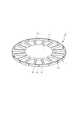
次に図2を参する。図2に示されたアキシャルギャップモータは、下記のように回転子10が従来のアキシャルギャップモータの回転子と異なっている。回転子10は、出力シャフト(図示せず)と共に回転するように固定された円盤状の支持部材12を含み、この支持部材12は、中心のハブ部13と、複数の磁石セグメント11が取り付けられた外周部14とから成る、いわゆるコアレス回転子形状となっており、非磁性体、例えばステンレススチールから構成されている。 Reference is now made to FIG. In the axial gap motor shown in FIG. 2, the
図1に明瞭に示されるように回転子10の支持部材12の外周部14には複数の永久磁石セグメント11が円周方向に等しい回転角で隔置されている。この永久磁石セグメント11は、高価な稀土類を含まないフェライト磁石から構成されている。これら磁石セグメント11は、磁石セグメント11と同じ形状となるよう支持部材12に形成された取り付け孔16に嵌合され、固定されている。固定方法として、焼き嵌め、接着剤を用いた接着方法、電気スポット溶接などを使用できる。 As clearly shown in FIG. 1, a plurality of
トルクリップルおよびコギングトルク低減のため、磁石セグメント11の側面には、所定のスキュー角(中心軸から延びる放射状軸に対する磁石セグメント11の側面の角度)が付けられ、平面形状が、略台形となっている。これら磁石セグメント11の間には、スポーク状部分15が形成され、これらスポーク状部分15は、ハブ部分13から支持部材12の外周縁部17まで径方向に延びている In order to reduce torque ripple and cogging torque, a predetermined skew angle (angle of the side surface of the
図1から3に示されるように、磁石セグメント取り付け孔18の外側の中心から支持部材12の外周縁部17まで径方向に切り欠き部分18が延びている。この切り欠き18は、支持部材12の厚み方向に完全に貫通する孔でも良いし、支持部材12で渦電流が生じない程度に材料を除去した非貫通孔でもよい。このため、磁石セグメント11と同じ数の取り付け孔18が支持部材12の外周縁部17に等間隔に位置する。これら、切り欠き部分18を設けたことによる支持部材12の強度低下および支持部材12の周辺における乱流発生を防止するため、これら切り欠き部分18に非導電性および耐熱性を有する樹脂、例えばフェノール樹脂、エポキシ樹脂、メラミン樹脂を充填し、充填面と支持部材12の表面とを面一にすることが好ましい。 As shown in FIGS. 1 to 3, a
図3に誇張した状態に示されるように、取り付け孔16から支持部材11の外周縁部17まで径方向外側に向かって幅が次第に狭くなるように切り欠き部分18を形成してもよい。このような形状にすることにより、支持部材11、すなわち、回転子10が高速回転する際に生じる遠心力による、充填材料の飛び出しを抑制することが可能となる。 As shown in an exaggerated state in FIG. 3, the
更に支持部材11の外周縁部17のまわりに絶縁性高強度材料から構成されたリム部材19を巻いてもよい。この絶縁性高強度材料をガラス繊維またはカーボンファイバーで補強されたプラスチックとすることができる。このようなリム部材19を設けることにより、支持部材11の強度低下を補償すると共に、充填材料の飛び出しを抑制できる。このようにリム部材19を設けることにより、実際に高回転(10000rpm)バースト試験(安全率2倍)に耐えることがわかった Further, a
切り欠き部分18を設けない比較例であるモータと切り欠き部分18を設けた実施例であるアキシャルギャップモータ(10kW)について実施した特性比較試験の結果が図4に示されている。この表から判るように、比較例のモータを1600rpmで回転したときの渦電流損は、169.93wであるのに対し、切り欠き部分を設けた実施例のモータを同じ1600rpmで回転したときの渦電流損は、9.90Wであり、比較例のモータを2800rpmで回転したときの渦電流損は、47.45wであるのに対し、切り欠き部分を設けた実施例のモータを同じ2800rpmで回転したときの渦電流損は、6.06Wであり、更に比較例のモータを5000rpmで回転したときの渦電流損は、778.96wであるのに対し、切り欠き部分を設けた実施例のモータを同じ5000rpmで回転したときの渦電流損は、62.52wとなった。 FIG. 4 shows the result of a characteristic comparison test performed on a motor that is a comparative example in which the notched
上記のように、本発明により、回転子10を構成する支持部材11の外周縁部17の切り欠き部分18を設けたことにより、切り欠き部分18を設けなかった場合に流れていた渦電流が遮断または低減され、モータで生じていた渦電流損が低下する。 As described above, according to the present invention, by providing the notched
また、図5に示されるように、グラフ上のA点、B点、C点の各々において、切り欠き部分を設けた実施例のモータと切り欠き部分を設けない比較例のモータの回転速度とトルクを同一にした状態で、それぞれのモータの効率を測定した。グラフからいずれも切り欠き部分を設けた実施例であるモータのほうが効率が高いことが判る。 Further, as shown in FIG. 5, at each of the points A, B, and C on the graph, the rotational speeds of the motor of the example in which the notched portion is provided and the motor of the comparative example in which the notched portion is not provided. The efficiency of each motor was measured with the same torque. From the graphs, it can be seen that the motor of the example in which the notched portions are provided has higher efficiency.
回転子10の両側に所定のギャップを残して配置される各固定子20,22には、磁石セグメント11と対向するよう複数のスロットおよびそれらの間のスロットが円周方向に等ピッチ角に隔置されているが、アキシャルギャップモータの固定子の構造は、当業者には周知であるので、その説明は省略する。 In each of the
10 回転子
11 磁石セグメント
12 支持部材
13 ハブ部
14 外周部
15 スポーク状部分
16 取り付け孔
17 外周縁部
18 切り欠き部分(貫通孔)
19 リム部分
20、22 固定子DESCRIPTION OF
19
Claims (7)
Translated fromJapanese前記複数の永久磁石セグメントの各々が取り付けられた、前記支持部材の取り付け孔と前記支持部材の外周縁部との間に径方向に延びる切り欠き部分が設けられ、
前記支持部材の外周部に絶縁性高強度材料から構成されたリム部材が巻かれていることを特徴とする、
アキシャルギャップモータ。A plurality of permanent magnet segments attached to the support member in a state of being spaced circumferentially at an equal pitch angle between the disc-shaped support member and the hub portion and the outer peripheral portion of the support member; A rotor fixed to the output shaft so as to be able to rotate together with the output shaft, and a fixed disposed opposite to the rotor, leaving a predetermined gap with respect to the rotor, on at least one side of the rotor An axial gap motor in which a plurality of field winding slots for generating a rotating magnetic field are spaced apart at equal pitch angles in the circumferential direction on the outer periphery of the stator.
A notch portion extending in the radial direction is provided between an attachment hole of the supportmember and an outer peripheral edge portion of the support member, to which each of the plurality of permanent magnet segments is attached,
A rim member made of an insulating high-strength material is wound around the outer periphery of the support member ,
Axial gap motor.
Priority Applications (7)
| Application Number | Priority Date | Filing Date | Title |
|---|---|---|---|
| JP2013256013AJP6255231B2 (en) | 2013-12-11 | 2013-12-11 | Axial gap motor |
| TW103133707ATWI625920B (en) | 2013-12-11 | 2014-09-29 | Axial gap motor |
| US15/102,571US10122223B2 (en) | 2013-12-11 | 2014-10-03 | Axial gap motor |
| CN201480067239.9ACN106233578B (en) | 2013-12-11 | 2014-10-03 | Axial Gap Motor |
| KR1020167015229AKR102232732B1 (en) | 2013-12-11 | 2014-10-03 | Axial gap motor |
| PCT/JP2014/076513WO2015087604A1 (en) | 2013-12-11 | 2014-10-03 | Axial gap motor |
| EP14869062.1AEP3082226B1 (en) | 2013-12-11 | 2014-10-03 | Axial gap motor |
Applications Claiming Priority (1)
| Application Number | Priority Date | Filing Date | Title |
|---|---|---|---|
| JP2013256013AJP6255231B2 (en) | 2013-12-11 | 2013-12-11 | Axial gap motor |
Publications (2)
| Publication Number | Publication Date |
|---|---|
| JP2015116033A JP2015116033A (en) | 2015-06-22 |
| JP6255231B2true JP6255231B2 (en) | 2017-12-27 |
Family
ID=53370923
Family Applications (1)
| Application Number | Title | Priority Date | Filing Date |
|---|---|---|---|
| JP2013256013AActiveJP6255231B2 (en) | 2013-12-11 | 2013-12-11 | Axial gap motor |
Country Status (7)
| Country | Link |
|---|---|
| US (1) | US10122223B2 (en) |
| EP (1) | EP3082226B1 (en) |
| JP (1) | JP6255231B2 (en) |
| KR (1) | KR102232732B1 (en) |
| CN (1) | CN106233578B (en) |
| TW (1) | TWI625920B (en) |
| WO (1) | WO2015087604A1 (en) |
Families Citing this family (39)
| Publication number | Priority date | Publication date | Assignee | Title |
|---|---|---|---|---|
| JP6255231B2 (en)* | 2013-12-11 | 2017-12-27 | 株式会社ダイナックス | Axial gap motor |
| US10559864B2 (en) | 2014-02-13 | 2020-02-11 | Birmingham Technologies, Inc. | Nanofluid contact potential difference battery |
| CN105099024A (en)* | 2015-07-27 | 2015-11-25 | 湖南德力科威科技有限公司 | Rotor structure of permanent magnet direct-current motor |
| US11139707B2 (en) | 2015-08-11 | 2021-10-05 | Genesis Robotics And Motion Technologies Canada, Ulc | Axial gap electric machine with permanent magnets arranged between posts |
| WO2018010031A1 (en)* | 2016-07-15 | 2018-01-18 | Genesis Robotics Llp | Axial gap electric machine with permanent magnets arranged between posts |
| US11121596B2 (en) | 2016-02-29 | 2021-09-14 | Denso Corporation | Stator of brushless motor, brushless motor, and method of manufacturing stator of brushless motor |
| EP3443643A4 (en) | 2016-04-13 | 2019-12-25 | Genesis Robotics and Motion Technologies Canada, ULC | ELECTRICAL MACHINE WITH AXIAL THRUST BEARINGS |
| DE102016004694B4 (en)* | 2016-04-19 | 2020-03-12 | eMoSys GmbH | Electronically controlled automatic seat belt system of a vehicle occupant restraint system |
| JP6700596B2 (en)* | 2016-06-21 | 2020-05-27 | 株式会社デンソー | Rotor for axial gap motor and axial gap motor |
| FR3064423B1 (en)* | 2017-03-22 | 2019-11-15 | Whylot Sas | ROTOR FOR MOTOR OR ELECTROMAGNETIC GENERATOR WITH ALVEOLAR STRUCTURE COMPRISING ALVEOLES FOR THE HOUSING OF RESPECTIVE MAGNETS |
| CN108736602B (en)* | 2017-04-14 | 2021-05-14 | 台达电子工业股份有限公司 | Axial flux electric machine |
| CN115347697A (en)* | 2017-05-26 | 2022-11-15 | 靛蓝技术股份有限公司 | Magnetic Rotor Assembly |
| CN107040106A (en)* | 2017-06-02 | 2017-08-11 | 中国科学院工程热物理研究所 | A kind of high-speed permanent magnetic disc type electric machine |
| CN109149810A (en)* | 2017-06-18 | 2019-01-04 | 南京理工大学 | A kind of axial magnetic flux disk type switch magnetoresistance electrical machinery with rotor chute structure |
| PL233865B1 (en)* | 2017-07-28 | 2019-12-31 | Equelo Spolka Z Ograniczona Odpowiedzialnoscia | Electric machine |
| JP6676014B2 (en)* | 2017-08-07 | 2020-04-08 | 三菱重工業株式会社 | Axial gap motor and rotor manufacturing method |
| JP6946120B2 (en)* | 2017-09-04 | 2021-10-06 | 株式会社神戸製鋼所 | Axial gap type rotary electric machine |
| CN109691908B (en)* | 2017-10-23 | 2022-04-22 | 佛山市顺德区美的电热电器制造有限公司 | Magnetic disc, stirring cutter assembly and food processor |
| DE102018105136A1 (en)* | 2018-03-06 | 2019-09-12 | Gkn Sinter Metals Engineering Gmbh | Method for operating a pump arrangement |
| FR3084300B1 (en)* | 2018-07-24 | 2021-05-21 | Univ Le Havre Normandie | MOTORIZED WHEEL |
| CN109194082B (en)* | 2018-09-30 | 2020-07-07 | 沈阳工业大学 | Amorphous alloy axial flux motor with wide field weakening speed expansion and low rotor loss |
| US10892654B2 (en)* | 2018-11-09 | 2021-01-12 | Shenzhen Shanxiang Intelligent Technology Enterprise | Axial magnetic field motor with grain-oriented silicon steel sheets |
| US11031835B2 (en) | 2019-03-27 | 2021-06-08 | Roderick James Brogan | Axial flux induction motor or generator |
| CN110635641B (en)* | 2019-09-24 | 2020-10-27 | 哈尔滨工业大学 | Axial magnetic field reverse salient pole permanent magnet synchronous motor |
| CN111884368B (en)* | 2019-11-22 | 2021-05-18 | 山东精创磁电产业技术研究院有限公司 | Axial magnetic field motor |
| CN111010009A (en)* | 2019-11-26 | 2020-04-14 | 北京动力机械研究所 | Multi-phase high-reliability permanent magnet disc type motor |
| JP7415487B2 (en)* | 2019-11-28 | 2024-01-17 | セイコーエプソン株式会社 | axial gap motor |
| CN111181337B (en)* | 2020-02-26 | 2021-12-21 | 安徽美芝精密制造有限公司 | Rotor assembly, assembling method thereof, motor and electric vehicle |
| JP7477377B2 (en)* | 2020-06-17 | 2024-05-01 | 株式会社日立産機システム | Axial gap type rotating electric motor |
| US11552516B2 (en) | 2020-09-04 | 2023-01-10 | Hyundai Motor Company | Rotor of axial flux motor |
| CN113364179B (en)* | 2021-06-21 | 2023-03-14 | 上海盘毂动力科技股份有限公司 | Rotor capable of reducing eddy current loss |
| CN115250049A (en)* | 2022-05-16 | 2022-10-28 | 西安交通大学 | An Electric Excitation Transformer Inverter Based on Double Stator Axial Flux Motor Design |
| US12160139B2 (en) | 2022-06-09 | 2024-12-03 | Regal Beloit Australia Pty Ltd | Variable torque constant electric machines having a radial spoked rotor with axial flux magnet plates and methods thereof |
| KR102457142B1 (en)* | 2022-07-28 | 2022-10-20 | 윤성순 | Single phase inverter motor with a core in triangular shape |
| US12206289B2 (en) | 2022-08-26 | 2025-01-21 | Regal Beloit America, Inc. | Radial spoked rotor with axial assist magnets |
| KR102739939B1 (en) | 2023-03-24 | 2024-12-10 | 명화공업주식회사 | Motor |
| KR20250005676A (en) | 2023-07-03 | 2025-01-10 | 현대자동차주식회사 | Stator and motor including the same |
| WO2025208125A1 (en)* | 2024-03-29 | 2025-10-02 | Conifer Systems, Inc. | Rotor design for high-speed applications using segmented magnets |
| CN119651996A (en)* | 2024-11-25 | 2025-03-18 | 苏州指尖智擎科技有限公司 | A motor drive assembly and a robot hand using the same |
Family Cites Families (19)
| Publication number | Priority date | Publication date | Assignee | Title |
|---|---|---|---|---|
| US4187441A (en)* | 1977-03-23 | 1980-02-05 | General Electric Company | High power density brushless dc motor |
| GB8817760D0 (en)* | 1988-07-26 | 1988-09-01 | Rolls Royce Plc | Electrical power generator |
| JP2004350427A (en)* | 2003-05-22 | 2004-12-09 | Denso Corp | Rotating electric machine and its rotor |
| US20070024147A1 (en)* | 2003-08-18 | 2007-02-01 | Hirzel Andrew D | Selective alignment of stators in axial airgap electric devices comprising low-loss materials |
| JP4613599B2 (en)* | 2004-12-14 | 2011-01-19 | 日産自動車株式会社 | Rotor structure of axial gap type rotating electrical machine |
| JP2007043864A (en)* | 2005-08-05 | 2007-02-15 | Fujitsu General Ltd | Axial gap type synchronous machine |
| JP5277514B2 (en)* | 2005-12-15 | 2013-08-28 | 日産自動車株式会社 | Method for manufacturing rotor core with magnet of rotating electrical machine |
| GB0613570D0 (en)* | 2006-07-07 | 2006-08-16 | Imp Innovations Ltd | An electrical machine |
| JP4169055B2 (en)* | 2006-07-14 | 2008-10-22 | ダイキン工業株式会社 | Rotating electric machine |
| GB0800225D0 (en)* | 2008-01-07 | 2008-02-13 | Evo Electric Ltd | A rotor for an electrical machine |
| JP5256778B2 (en)* | 2008-02-28 | 2013-08-07 | 日本電産株式会社 | Motor rotor and motor |
| GB0813032D0 (en)* | 2008-07-16 | 2008-08-20 | Cummins Generator Technologies | Axial flux machine |
| US8310123B2 (en)* | 2008-07-28 | 2012-11-13 | Direct Drive Systems, Inc. | Wrapped rotor sleeve for an electric machine |
| JP4678549B2 (en)* | 2008-10-09 | 2011-04-27 | 本田技研工業株式会社 | Axial gap type motor |
| JP5046051B2 (en)* | 2009-01-28 | 2012-10-10 | 本田技研工業株式会社 | Axial gap type motor |
| JP5027169B2 (en)* | 2009-01-30 | 2012-09-19 | 本田技研工業株式会社 | Axial gap type motor and rotor manufacturing method thereof |
| JP2011055577A (en)* | 2009-08-31 | 2011-03-17 | Daikin Industries Ltd | Rotor |
| TWM393106U (en)* | 2010-06-24 | 2010-11-21 | Jian-Jie Huang | High performance generator tray which without a iron core |
| JP6255231B2 (en)* | 2013-12-11 | 2017-12-27 | 株式会社ダイナックス | Axial gap motor |
- 2013
- 2013-12-11JPJP2013256013Apatent/JP6255231B2/enactiveActive
- 2014
- 2014-09-29TWTW103133707Apatent/TWI625920B/enactive
- 2014-10-03EPEP14869062.1Apatent/EP3082226B1/enactiveActive
- 2014-10-03KRKR1020167015229Apatent/KR102232732B1/enactiveActive
- 2014-10-03CNCN201480067239.9Apatent/CN106233578B/enactiveActive
- 2014-10-03USUS15/102,571patent/US10122223B2/enactiveActive
- 2014-10-03WOPCT/JP2014/076513patent/WO2015087604A1/enactiveApplication Filing
Also Published As
| Publication number | Publication date |
|---|---|
| TW201524087A (en) | 2015-06-16 |
| EP3082226B1 (en) | 2020-04-29 |
| WO2015087604A1 (en) | 2015-06-18 |
| US10122223B2 (en) | 2018-11-06 |
| CN106233578A (en) | 2016-12-14 |
| EP3082226A1 (en) | 2016-10-19 |
| EP3082226A4 (en) | 2017-07-19 |
| JP2015116033A (en) | 2015-06-22 |
| TWI625920B (en) | 2018-06-01 |
| CN106233578B (en) | 2019-06-11 |
| KR20160091919A (en) | 2016-08-03 |
| KR102232732B1 (en) | 2021-03-25 |
| US20160322869A1 (en) | 2016-11-03 |
Similar Documents
| Publication | Publication Date | Title |
|---|---|---|
| JP6255231B2 (en) | Axial gap motor | |
| WO2015133205A1 (en) | Axial gap motor | |
| WO2015104611A2 (en) | A rotor for an electric motor or generator | |
| JP6345918B2 (en) | Axial gap motor | |
| JP2010525774A (en) | Motor having rotor arranged concentrically and driving device having said motor | |
| US20160105065A1 (en) | Rotating electric machine for vehicle | |
| JP2014045630A (en) | Rotating electric machine | |
| JP2015130724A (en) | Motor core and motor | |
| WO2017038326A1 (en) | Rotor, rotating electrical machine provided therewith, and method of manufacturing rotor | |
| KR20090109248A (en) | Motor with multi-stage yoke and driving device using the motor | |
| JP2023545583A (en) | Electric disc motor to drive the rim | |
| CN102310763B (en) | In-wheel motor and electric vehicle | |
| JP2015216715A (en) | Axial gap type rotating electrical machine | |
| JP6088465B2 (en) | Drive unit | |
| JP6154452B2 (en) | Wheel-in motor and electric vehicle | |
| HK40073449A (en) | Stator of a rotating electrical machine, rotating electrical machine and drive unit having an electrical machine of this type | |
| JP6126873B2 (en) | Permanent magnet rotating electric machine | |
| JP4703282B2 (en) | Rotating electrical machine rotor | |
| JP2016171660A (en) | Rotor of dynamo-electric machine | |
| CN117879199A (en) | Mixed permanent magnet memory motor capable of reducing loss | |
| JP2025104783A (en) | Motors and electric vehicles | |
| KR101029690B1 (en) | In-wheel drive | |
| JP2021097457A (en) | Rotator of rotary electric machine and rotary electric machine | |
| JP2018137955A (en) | Motor with resolver |
Legal Events
| Date | Code | Title | Description |
|---|---|---|---|
| A621 | Written request for application examination | Free format text:JAPANESE INTERMEDIATE CODE: A621 Effective date:20160511 | |
| A131 | Notification of reasons for refusal | Free format text:JAPANESE INTERMEDIATE CODE: A131 Effective date:20170413 | |
| A521 | Request for written amendment filed | Free format text:JAPANESE INTERMEDIATE CODE: A523 Effective date:20170612 | |
| TRDD | Decision of grant or rejection written | ||
| A01 | Written decision to grant a patent or to grant a registration (utility model) | Free format text:JAPANESE INTERMEDIATE CODE: A01 Effective date:20171121 | |
| A61 | First payment of annual fees (during grant procedure) | Free format text:JAPANESE INTERMEDIATE CODE: A61 Effective date:20171204 | |
| R150 | Certificate of patent or registration of utility model | Ref document number:6255231 Country of ref document:JP Free format text:JAPANESE INTERMEDIATE CODE: R150 | |
| S111 | Request for change of ownership or part of ownership | Free format text:JAPANESE INTERMEDIATE CODE: R313117 | |
| R350 | Written notification of registration of transfer | Free format text:JAPANESE INTERMEDIATE CODE: R350 | |
| R250 | Receipt of annual fees | Free format text:JAPANESE INTERMEDIATE CODE: R250 | |
| R250 | Receipt of annual fees | Free format text:JAPANESE INTERMEDIATE CODE: R250 | |
| R250 | Receipt of annual fees | Free format text:JAPANESE INTERMEDIATE CODE: R250 | |
| R250 | Receipt of annual fees | Free format text:JAPANESE INTERMEDIATE CODE: R250 | |
| R250 | Receipt of annual fees | Free format text:JAPANESE INTERMEDIATE CODE: R250 |