JP6251745B2 - Gimbal-type flexible member having two-stage starting structure and suspension - Google Patents
Gimbal-type flexible member having two-stage starting structure and suspensionDownload PDFInfo
- Publication number
- JP6251745B2 JP6251745B2JP2015532087AJP2015532087AJP6251745B2JP 6251745 B2JP6251745 B2JP 6251745B2JP 2015532087 AJP2015532087 AJP 2015532087AJP 2015532087 AJP2015532087 AJP 2015532087AJP 6251745 B2JP6251745 B2JP 6251745B2
- Authority
- JP
- Japan
- Prior art keywords
- pair
- motor
- tongue
- gimbal
- struts
- Prior art date
- Legal status (The legal status is an assumption and is not a legal conclusion. Google has not performed a legal analysis and makes no representation as to the accuracy of the status listed.)
- Active
Links
- 239000000725suspensionSubstances0.000titleclaimsdescription82
- 238000005452bendingMethods0.000claimsdescription20
- 239000002184metalSubstances0.000claimsdescription13
- 229910052751metalInorganic materials0.000claimsdescription13
- 230000004913activationEffects0.000claimsdescription8
- 229910001220stainless steelInorganic materials0.000description59
- 239000010935stainless steelSubstances0.000description59
- 239000004020conductorSubstances0.000description24
- 239000000853adhesiveSubstances0.000description14
- 230000001070adhesive effectEffects0.000description14
- 230000009471actionEffects0.000description13
- 230000008859changeEffects0.000description8
- RYGMFSIKBFXOCR-UHFFFAOYSA-NCopperChemical compound[Cu]RYGMFSIKBFXOCR-UHFFFAOYSA-N0.000description7
- 229910052802copperInorganic materials0.000description7
- 239000010949copperSubstances0.000description7
- 239000004642PolyimideSubstances0.000description6
- 229920001721polyimidePolymers0.000description6
- 238000010586diagramMethods0.000description5
- 230000006870functionEffects0.000description5
- 239000000463materialSubstances0.000description5
- 238000004904shorteningMethods0.000description4
- 239000004593EpoxySubstances0.000description3
- 240000004050Pentaglottis sempervirensSpecies0.000description3
- 235000004522Pentaglottis sempervirensNutrition0.000description3
- 239000003989dielectric materialSubstances0.000description3
- 230000004048modificationEffects0.000description3
- 238000012986modificationMethods0.000description3
- 230000002787reinforcementEffects0.000description3
- 230000004044responseEffects0.000description3
- 238000013459approachMethods0.000description2
- PCHJSUWPFVWCPO-UHFFFAOYSA-NgoldChemical compound[Au]PCHJSUWPFVWCPO-UHFFFAOYSA-N0.000description2
- 239000010931goldSubstances0.000description2
- 229910052737goldInorganic materials0.000description2
- 230000007935neutral effectEffects0.000description2
- 239000012779reinforcing materialSubstances0.000description2
- 229910000679solderInorganic materials0.000description2
- 239000003351stiffenerSubstances0.000description2
- 230000007704transitionEffects0.000description2
- 238000007792additionMethods0.000description1
- 230000008901benefitEffects0.000description1
- 230000008878couplingEffects0.000description1
- 238000010168coupling processMethods0.000description1
- 238000005859coupling reactionMethods0.000description1
- 230000009849deactivationEffects0.000description1
- 230000009977dual effectEffects0.000description1
- 239000007769metal materialSubstances0.000description1
- 150000002739metalsChemical class0.000description1
- 238000000034methodMethods0.000description1
- 238000007747platingMethods0.000description1
- 230000003014reinforcing effectEffects0.000description1
- 229910052709silverInorganic materials0.000description1
- 239000004332silverSubstances0.000description1
- 239000007858starting materialSubstances0.000description1
- 239000003190viscoelastic substanceSubstances0.000description1
Images


Classifications
- G—PHYSICS
- G11—INFORMATION STORAGE
- G11B—INFORMATION STORAGE BASED ON RELATIVE MOVEMENT BETWEEN RECORD CARRIER AND TRANSDUCER
- G11B5/00—Recording by magnetisation or demagnetisation of a record carrier; Reproducing by magnetic means; Record carriers therefor
- G11B5/48—Disposition or mounting of heads or head supports relative to record carriers ; arrangements of heads, e.g. for scanning the record carrier to increase the relative speed
- G11B5/4806—Disposition or mounting of heads or head supports relative to record carriers ; arrangements of heads, e.g. for scanning the record carrier to increase the relative speed specially adapted for disk drive assemblies, e.g. assembly prior to operation, hard or flexible disk drives
- G11B5/4826—Mounting, aligning or attachment of the transducer head relative to the arm assembly, e.g. slider holding members, gimbals, adhesive
- G11B5/483—Piezoelectric devices between head and arm, e.g. for fine adjustment
- G—PHYSICS
- G11—INFORMATION STORAGE
- G11B—INFORMATION STORAGE BASED ON RELATIVE MOVEMENT BETWEEN RECORD CARRIER AND TRANSDUCER
- G11B5/00—Recording by magnetisation or demagnetisation of a record carrier; Reproducing by magnetic means; Record carriers therefor
- G11B5/48—Disposition or mounting of heads or head supports relative to record carriers ; arrangements of heads, e.g. for scanning the record carrier to increase the relative speed
- G11B5/4806—Disposition or mounting of heads or head supports relative to record carriers ; arrangements of heads, e.g. for scanning the record carrier to increase the relative speed specially adapted for disk drive assemblies, e.g. assembly prior to operation, hard or flexible disk drives
- G11B5/4833—Structure of the arm assembly, e.g. load beams, flexures, parts of the arm adapted for controlling vertical force on the head
- G—PHYSICS
- G11—INFORMATION STORAGE
- G11B—INFORMATION STORAGE BASED ON RELATIVE MOVEMENT BETWEEN RECORD CARRIER AND TRANSDUCER
- G11B5/00—Recording by magnetisation or demagnetisation of a record carrier; Reproducing by magnetic means; Record carriers therefor
- G11B5/48—Disposition or mounting of heads or head supports relative to record carriers ; arrangements of heads, e.g. for scanning the record carrier to increase the relative speed
- G11B5/4806—Disposition or mounting of heads or head supports relative to record carriers ; arrangements of heads, e.g. for scanning the record carrier to increase the relative speed specially adapted for disk drive assemblies, e.g. assembly prior to operation, hard or flexible disk drives
- G11B5/4853—Constructional details of the electrical connection between head and arm
Landscapes
- Supporting Of Heads In Record-Carrier Devices (AREA)
- Adjustment Of The Magnetic Head Position Track Following On Tapes (AREA)
- Moving Of The Head To Find And Align With The Track (AREA)
Description
Translated fromJapanese本発明は、ディスクドライブ、及び、ディスクドライブのサスペンションに関する。特に、本発明は2段始動(dual stage actuation(DSA))サスペンションに関する。 The present invention relates to a disk drive and a suspension of the disk drive. In particular, the present invention relates to a dual stage actuation (DSA) suspension.
DSAディスクドライブヘッドサスペンション、及び、DSAサスペンションを組み込んだディスクドライブが一般的に既知であり、市販されている。例えば、サスペンションのベースプレート又は他の取付部分上、すなわちサスペンションのばね又はヒンジ領域に対して近位のアクチュエーション構造部を有するDSAサスペンションが、Okawaraの特許文献1、Shumの特許文献2、Fuchinoの特許文献3、及び、Imamuraの特許文献4に記載されている。サスペンションのロードビーム又はジンバル部分、すなわちばね又はヒンジ領域に対して遠位に位置するアクチュエーション構造部を有するDSAサスペンションも既知であり、例えば、Jurgensonの特許文献5、Krinkeの特許文献6及びYaoの特許文献7に開示されている。上記で明記した特許及び特許出願は全て、あらゆる目的でそれらの全体が参照により本明細書に援用される。 DSA disk drive head suspensions and disk drives incorporating DSA suspensions are generally known and commercially available. For example, DSA suspensions having an actuation structure proximal to the suspension base plate or other mounting portion, ie, to the spring or hinge region of the suspension, are described in Okawara, US Pat.
改良されたDSAサスペンションが依然として必要とされている。性能を高めたDSAサスペンションが望ましい。サスペンションは効率的に製造できることが望まれる。 There is still a need for improved DSA suspensions. A DSA suspension with improved performance is desirable. It is desirable that the suspension can be manufactured efficiently.
種々の実施形態は、ジンバル形撓み部材(flexure)に2段始動構造部を有するサスペンションに関する。サスペンションは、長手方向軸を有するロードビーム、及び、ロードビームに取着される撓み部材を備える。撓み部材は、一対のばねアーム、ばねアーム間に位置するとともに一対のばねアームによって構造的に支持されるタング、及び、一対の支柱を備える。これらの支柱は、一対のばねアームとタングとの間にそれぞれ位置決めされる。各支柱は長手方向軸を有する。支柱の長手方向軸は互いに対して平行であるとともにずらされる。サスペンションは、撓み部材に取り付けられるスライダ及びモータを更に備える。モータは、支柱の軸に平行であるとともにロードビームの長手方向軸に垂直な長手方向軸を有する。モータの電気的起動によって一対の支柱が曲がり、スライダを移動させる。 Various embodiments relate to a suspension having a two-stage starting structure on a gimbal-shaped flexure. The suspension includes a load beam having a longitudinal axis and a flexure member attached to the load beam. The bending member includes a pair of spring arms, a tongue positioned between the spring arms and structurally supported by the pair of spring arms, and a pair of struts. These struts are each positioned between a pair of spring arms and a tongue. Each strut has a longitudinal axis. The longitudinal axes of the struts are parallel and offset with respect to each other. The suspension further includes a slider and a motor attached to the deflecting member. The motor has a longitudinal axis that is parallel to the axis of the column and perpendicular to the longitudinal axis of the load beam. A pair of struts are bent by the electrical activation of the motor, and the slider is moved.
種々の実施形態は、ジンバル形撓み部材に2段始動構造部を有するサスペンションに関する。サスペンションは、それ自体が一対のばねアーム、ばねアーム間に位置するタング、及び、一対の支柱を備える撓み部材を備え、一対の支柱は、一対のばねアーム及びタングをそれぞれ接続する。サスペンションは、タングに取り付けられるスライダを更に備える。サスペンションは、一対のばねアームにそれぞれ取り付けられる両端を有するモータを更に備える。モータの電気的起動によって一対の支柱が曲がり、スライダを移動させる。そのような起動によってタングが回転するが、ばねアームは相対的に静止したままである。 Various embodiments relate to a suspension having a two-stage starting structure on a gimbal-shaped flexure. The suspension itself includes a pair of spring arms, a tongue positioned between the spring arms, and a bending member including a pair of support columns, and the pair of support columns respectively connect the pair of spring arms and the tongue. The suspension further includes a slider attached to the tongue. The suspension further includes a motor having both ends respectively attached to the pair of spring arms. A pair of struts are bent by the electrical activation of the motor, and the slider is moved. Such activation causes the tongue to rotate, but the spring arm remains relatively stationary.
種々の実施形態は、ジンバル形撓み部材に2段始動構造部を有するサスペンションに関する。撓み部材は、一対のばねアーム、ばねアーム間に位置するとともに一対のばねアームによって構造的に支持されるタング、及び、一対のモータ取付パッドを備え、モータ取付パッドは一対の支柱によってタングにそれぞれ接続される。サスペンションは、スライダ、及び、一対のモータ取付パッドにそれぞれ取り付けられる両端を有するモータを更に備え、スライダはモータに取り付けられ、モータの電気的起動によって一対の支柱が曲がり、スライダを移動させる。タングは、スライダがモータの電気的起動によって移動される間に相対的に静止したままである。 Various embodiments relate to a suspension having a two-stage starting structure on a gimbal-shaped flexure. The bending member includes a pair of spring arms, a tongue positioned between the spring arms and structurally supported by the pair of spring arms, and a pair of motor mounting pads. Connected. The suspension further includes a slider and a motor having both ends respectively attached to a pair of motor attachment pads. The slider is attached to the motor, and the pair of struts are bent by the electrical activation of the motor to move the slider. The tongue remains relatively stationary while the slider is moved by electrical activation of the motor.
種々の実施形態の更なる特徴及び変更形態が、本明細書において更に説明されるとともに図面に示される。複数の実施形態が開示されるが、本開示の更に他の実施形態が、本開示の例示的な実施形態を示し記載する以下の詳細な説明から当業者には明らかとなるであろう。したがって、図面及び詳細な説明は、事実上例示的なものとみなされ、限定的であるとみなされるべきではない。 Additional features and modifications of the various embodiments are further described herein and shown in the drawings. While multiple embodiments are disclosed, still other embodiments of the present disclosure will be apparent to those skilled in the art from the following detailed description, which illustrates and describes exemplary embodiments of the present disclosure. Accordingly, the drawings and detailed description are to be regarded as illustrative in nature and not as restrictive.
本開示の主題は種々の変更形態及び代替形態が可能であるが、特定の実施形態が例として図面に示され、以下で詳細に記載される。しかしながら、本発明は、本開示を、開示される特定の実施形態に限定しない。それどころか、本開示は、添付の特許請求の範囲によって規定されるような本開示の範囲内に入る全ての変更形態、均等物及び代替形態を包含することが意図される。 While the subject matter of the disclosure is susceptible to various modifications and alternative forms, specific embodiments are shown by way of example in the drawings and are described in detail below. However, the present invention is not limited to the specific embodiments disclosed. On the contrary, the disclosure is intended to cover all modifications, equivalents, and alternatives falling within the scope of the disclosure as defined by the appended claims.
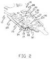
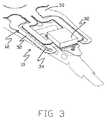
図1は、本発明の第1の実施形態(すなわち、ステンレス鋼側バージョン)による、同一位置に配置されるか又はジンバルベースの2段始動(DSA)構造部14を備える撓み部材12を有するサスペンション10のロードビーム側の等角図である。図2は、サスペンション10の遠位端の詳細な等角図である。図3は、サスペンション10の遠位端の撓み部材側の詳細な等角図であり、図2に示されているものと反対の側を示す。図1に示されているように、サスペンション10は、近位取付構造部としてベースプレート16を含む。図1に更に示されているように、サスペンション10は、ばね又はヒンジ領域22に沿ってベースプレート16に連結される剛性の又はビーム領域20を有するロードビーム18を含む。ロードビーム18はステンレス鋼から形成することができる。 FIG. 1 shows a suspension having a deflecting
撓み部材12は、撓み部材12の遠位端にジンバル24を含む。DSA構造部14が、ロードビーム18の遠位端に隣接してジンバル24に配置される。図2に最も良く示されているように、サスペンション10は、ロードビーム18の止め部分30に係合するように構成されているタブ28を含むジンバルリミッタ26を備える。ヘッドスライダ32が、サスペンション10の、ロードビーム18とは反対の側の、ジンバル24のスライダ取付領域又はタング33に取り付けられる。DSA構造部14は、ロードビーム18とヘッドスライダ32との間で撓み部材12のジンバル24に取り付けられる、図示の実施形態ではPZT又は他の圧電アクチュエータであるモータ34を含む。以下で更に詳細に記載するように、モータ34に印加される電気的な駆動信号に応じて、モータは、タング33及びスライダ32を含むジンバル24の部分を、概ね横断方向のトラッキング軸を中心に駆動する。 The
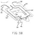
図4A及び図4Bは、図1に示されている撓み部材12及びDSA構造部14のステンレス鋼側の等角図である。モータ34は、タング33の更なる詳細を示すために図4Bには示されていない。図5A〜図5Fは、撓み部材12及びDSA構造部14のトレース側(すなわち、図4A及び図4Bに示されているものと反対の側)の等角図である。具体的には、図5A〜図5Fは、撓み部材12及びDSA構造部14を含む種々の層を示している。図5Bは、図5Aの図であるが、タング33の詳細を更に示すためにヘッドスライダ32が取り外されている。図5Cは、図5Bの図であるが、導電性材料層44を露出させるためにポリイミドカバーレイ46が取り外されており、導電性材料層44は、そうでなければポリイミドカバーレイ46の下にある、導電性材料層に形成されるトレース60及び他の構造を含む。図5Dは、図5Cの図であるが、そうでなければ導電性材料層44の下にある誘電体層42をより十分に露出させるために導電性材料層44が取り外されている。図5Eは、図5Dの図であるが、ステンレス鋼層40及びモータ34のみを示すために誘電材料層42が取り外されている。図5Fは、図5Eの図であるが、撓み部材12のステンレス鋼層40のみを示すためにモータ34が取り外されている。ステンレス鋼層40を代替的に別の金属又は剛性材料から形成してもよい。 4A and 4B are isometric views of the
図5A〜図5Fに示されているように、撓み部材12は、ステンレス鋼層40、ポリイミド又は他の誘電体層42、銅又は他の導電性材料層44及びポリイミドカバーレイ46等の、重なり合うばね用金属から形成される。誘電体層42は、ステンレス鋼層40の隣接する部分から、導電性材料層44に形成される構造を概ね絶縁する。カバーレイ46は、導電性材料層44に形成される構造を概ね覆って保護する。ジンバル24は、ベース部分50、ばねアーム52、及び、ステンレス鋼層40に形成される取付部分54を含む。ばねアーム52はベース部分50から延びる。タング33の一部である取付部分54は、ばねアーム52の遠位端部分の支持領域58から延びる一対の支柱56によってばねアーム52間で支持される。幾つかの実施形態では、一対の支柱56は、ばねアーム52間でタング33に接続するか又は別様に支持するステンレス鋼層40の唯一の部分である。具体的には、支柱56は、ばねアーム52とタング33との間の唯一の構造的な連結部であるものとすることができる。また、支柱56は、タング33に接続することによって、ベース部分50の遠位でばねアーム52間を接続するステンレス鋼層40の唯一の部分であるものとすることができる。図示のように、支柱56は、撓み部材12の長手方向軸に対して互いからずらされるか、又は、ばねアーム52に対してトラッキング軸を中心とした取付部分54の回転運動を提供するように別様に構成される。図8Bに最も良く示されているように(本明細書において更に説明する)、一対の支柱56のうちの一方の支柱56はモータ34の近位に配置され、一方で、一対の支柱56のうちの他方の支柱56はモータ34の遠位に配置され、モータ34が一対の支柱56の間にあるようにする。各支柱56は、サスペンション10の長手方向軸に対して概ね垂直に延びる長手方向軸を有する。支柱56の長手方向軸は、平行に延び、支柱56が応力を受けていない(例えば曲がっていない)ときは互いに交差しないか又は別様に重ならない。図5Fに示されているように、支柱56は、それぞれ、(図8Bの俯瞰斜視図から見て)X−Y平面においてステンレス鋼層40の最も狭い部分であるものとすることができ、一方で、ステンレス鋼層40の厚さは撓み部材12に沿って一貫しているものとすることができる。 As shown in FIGS. 5A-5F, the
図4A及び図5Eに最も良く示されているように、モータ34の両端は、ばねアーム52の支持領域58に(例えばエポキシ等の構造接着剤によって)付着する。このように、支持領域58はモータ取付パッドとして役立つ。誘電体層42の部分は、図4Bでは支柱56の下に延びる。図5Cに示されているように、導電性材料層44に形成されている複数のトレース60が、ベース部分50とタング33との間に、誘電体層42に形成される支持部分62上に延在する。複数のトレース60が、タング33の遠位領域の位置において終端し、スライダ32の読み書きヘッド(図示せず)の端子に電気的に取着されるように構成されている。他のトレース60は、モータ34の下でタング33の銅パッド64等の接点で終端する。図示の実施形態では、銅パッド64は、ばねアーム52間の概ね中央に位置付けられている。図4Bに最も良く示されているように、誘電体層42はパッド64上に開口を有する。例えば導電性接着剤を用いた構造的及び電気的な接続が、銅パッド64と、モータ34の電気端子との間でなされる。モータ34の端子(例えば接地端子)への別の電気的接続が、ディンプル36を通じてなされる(すなわち、ディンプル36はモータ34上の端子と電気的に接触する)。他の実施形態では、モータ34への電気的接続は、他の手法及び構造によってなすことができる。 As best shown in FIGS. 4A and 5E, both ends of the
図5A及び図5Bに示されているように、スライダ32はタング33のカバーレイ46に着座する。カバーレイ46はトレース60を保護する。支持部分62が撓み部材12の長手方向に対してずらされることを示す図5A〜図5Cに示されているように、撓み部材12の反対側のトレース60の部分は、支柱56と同様に互いからずらされる(例えば、トレースの部分は、図示の実施形態では支柱に重なる)。このタイプのずらされたトレースは、DSA構造部14のストローク性能を高めることができる。本発明の他の実施形態(図示せず)はずらされたトレースを有しない。なお、幾つかの実施形態では、支持部分62は、支柱56に対して、タング33へのごく僅かな機械的な支持を提供することができる。 As shown in FIGS. 5A and 5B, the
図6及び図7は、ジンバル24及びDSA構造部14を示す、サスペンション10の側面図である。図示のように、ディンプル36は、ロードビーム18を形成するステンレス鋼材料に形成される構造であり、かつ、ロードビーム18から延び、モータ34に係合し、更に、撓み部材12のベース部分50に対して面外でモータ34に接続されるジンバル24の部分を付勢することによって荷重点として機能する。撓み部材12の曲がり又は遷移部は、ディンプル36によってジンバル24を付勢するために、ばねアーム52に沿う任意の所望の位置に生じることができる。ディンプル36は、ディンプルが係合するモータ34の部分の端子(図示せず)に電気接触も提供することができる。例えば、ステンレス鋼ロードビーム18が電気的に接地されるか又は別様に電気回路の部分である場合、ディンプル36は、電気的接地電位、又は、モータ34の端子への電気的接続を提供することができる。本発明の他の実施形態(図示せず)は、これらの機能を提供するめっき構造等の他のディンプル構造を含む。ディンプル36は、金等の導電性材料でめっきし、同様に金等の導電性材料でめっきすることができるモータ34の端子への電気的接続を高めることができる。更に他の実施形態(図示せず)は、モータ34への接地又は他の電気的接続を提供するためにディンプル36以外の構造を用いる。1つのそのような実施形態では、例えば、支持領域58のうちの一方の端に別の銅パッドがあり、電気的接続(例えば接地接続)は、モータ34の端子と撓み部材12の支持領域の導電性材料パッドとの間の導電性接着剤等の構造によってなすことができる。幾つかの実施形態では、モータ34は、タング33の反対側の横方向端部分の間の位置でタング33に構造的に取着される。そのような実施形態では、モータ34は、ばねアーム52の支持領域58に取着されることに加えて、ジンバル24のタング33に取着される。 6 and 7 are side views of the
DSA構造部14の動作を、撓み部材12のジンバル24のステンレス鋼側の平面図である図8A〜図8Cを参照して記載する。図8Bに示されているように、DSA構造部14及びタング33は、トラッキング駆動信号がモータ34に印加されないときは、タング33がばねアーム52間の概ね中央に位置する状態で、中立の駆動されない状態にある。図8Aに示されているように、第1の電位(例えばプラス)のトラッキング駆動信号がモータ34に印加されると、モータの形状が変化し、その長さが概ね広がる。この形状の変化によって、図8Aに示されているように支持領域58間の距離が増大し、これは、連結支柱56の機械的な作用と関連して、タング33を、トラッキング軸を中心にばねアーム52に対して第1の方向に移動又は回転させる。図示のように、モータ34の延長によって、ジンバル24が横方向に伸張し、支柱56が曲がる(例えば内方に撓む)。支柱56のずれた配置によって、支柱56は、タング33が第1の方向に回転するように曲がる。 The operation of the
図8Cに示されているように、第2の電位(例えばマイナス)のトラッキング駆動信号がモータ34に印加されると、モータの形状が変化し、その長さが概ね収縮する。この形状の変化によって、図8Cに示されているように支持領域58間の距離が減少し、これは、連結支柱56の機械的な作用と関連して、トラッキング軸を中心にばねアーム52に対して、タング33を第2の方向に移動又は回転させる。第2の方向は第1の方向とは反対である。図示のように、モータ34の短縮によって、ジンバル24が横方向に圧縮され、支柱56が曲がる(例えば外方に撓む)。支柱56のずれた配置によって、支柱56は、タング33が第2の方向に回転するように曲がる。ジンバル24の他の部分の、比較的僅かであるが、幾らかの面外の動きが、上述したようなDSA構造部14のトラッキング作用の間に生成される。本発明のこの実施形態の場合、タング33のスライダ取付領域が、ばねアーム52が静止しているか又は僅かに移動するため、ばねアーム52に対して概ね回転する。 As shown in FIG. 8C, when a tracking drive signal having a second potential (for example, minus) is applied to the
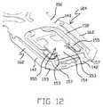
図9は、本発明の第2の実施形態(すなわちトレース側バージョン)による、同一位置に配置されるか又はジンバルベースの2段始動(DSA)構造部114を有する撓み部材112を備えるサスペンション110のロードビーム側の等角図である。サスペンション110の構成要素は、別途記載されるか又は図示されない限り、前述したサスペンション10と同様に構成することができる。図10は、サスペンション110の遠位端の等角図である。図11は、図10に示されているものと反対の側を示す、サスペンション110の遠位端の撓み部材側の等角図である。図10に示されているように、サスペンション110は、近位取付構造部としてベースプレート116を含む。図11に更に示されているように、サスペンション110は、ばね又はヒンジ領域122に沿ってベースプレート116に結合される剛性又はビーム領域120を有するロードビーム118を含む。ロードビーム118はステンレス鋼から形成することができる。撓み部材112は、その遠位端にジンバル124を含む。DSA構造部114は、ロードビーム118の遠位端に隣接してジンバル124に位置する。サスペンション110の図示の実施形態は、ロードビーム118の止め部分130に係合するように構成されているタブ128を含むジンバルリミッタ126も含む。DSA構造部114は、図示の実施形態では、撓み部材112の、ロードビーム118とは反対の側でタング133のモータ取付領域に取り付けられるPZTアクチュエータであるモータ134を含む。ヘッドスライダ132が、モータ134の、撓み部材112とは反対の側に取り付けられる。以下でより詳細に記載するように、モータ134に印加される電気駆動信号に応じて、モータは、タング133、モータ134及びスライダ132の部分を含むジンバル124の部分を、概ね横断方向のトラッキング軸を中心に駆動する。 FIG. 9 shows a
図12は、図9に示されている撓み部材112及びDSA構造部114のステンレス鋼側の詳細な等角図である。図13A〜図13Fは、図12に示されているものと反対の側を示す、撓み部材112及びDSA構造部114の等角図である。具体的には、図13A〜図13Fは、撓み部材112及びDSA構造部114を含む種々の層を示している。図13Bは、図13Aの図であるが、タング133のモータ134の詳細を更に示すためにヘッドスライダ132が取り外されている。図13Cは、図13Bの図であるが、タング133の細部を露出させるためにモータ134が取り外されている。図13Dは、図13Cの図であるが、トレース160を含む導電性材料層144、及び、導電性材料層144に形成される他の構造を露出させるためにカバーレイ146が取り外されている。図13Eは、図13Dの図であるが、誘電体層142を更に露出させるために導電性材料層144が取り外されている。図13Fは、図13Eの図であるが、撓み部材112のステンレス鋼層140のみを示すために誘電体層142が取り外されている。ステンレス鋼層140を代替的に別の金属又は剛性材料から形成してもよい。図示のように、撓み部材112は、ステンレス鋼層140、ポリイミド又は他の誘電体層142、銅又は他の導電性材料層144及びカバーレイ146等の、重なり合うばね用金属から形成される。誘電体層142は、導電性材料層144に形成される構造を、ステンレス鋼層140の隣接する部分から概ね絶縁する。カバーレイ146は、導電性材料層144に形成される構造を概ね覆って保護する。 FIG. 12 is a detailed isometric view of the
ジンバル124は、ベース部分150、ばねアーム152及びタング133の中央領域154を含む。ベース部分150、ばねアーム152及び中央領域154は、ステンレス鋼層140からそれぞれ形成される。ばねアーム152はベース部分150から延びる。タング133の中央部分である中央領域154は、ばねアーム152の遠位端に接続され、ばねアーム152間で支持される。同様にステンレス鋼層140に形成されるのは、一対の支柱153である。支柱153のそれぞれは、中央領域154の反対側の側面のうちの一方から延び、その外側端にモータ取付フラッグ又はパッド155を有する。図示のように、支柱153は、撓み部材112の長手方向軸に対して互いからずらされるか、又は、モータ134、及び、モータ134に取り付けられるヘッドスライダ132の、中央領域154に対するトラッキング軸を中心とした回転運動を提供するように別様に構成される。各支柱153は、サスペンション110の長手方向軸に対して概ね垂直に延びる長手方向軸を有する。支柱153の長手方向軸は、平行に延び、支柱153が応力を受けていない(例えば曲がっていない)ときは互いに交差しないか又は別様に重ならない。支柱153は、中央領域154とパッド155との間の唯一の構造的な連結部であるものとすることができる(例えば、中央領域154とパッド155とを接続するステンレス鋼層140の唯一の部分が支柱153であり、各パッド155につき1つの支柱153)。図13Fに示されているように、支柱153は、それぞれ、(図16B1の俯瞰斜視図から見て)X−Y平面においてステンレス鋼層140の最も狭い部分であるものとすることができ、一方で、ステンレス鋼層140の厚さは撓み部材112に沿って一貫しているものとすることができる。 The
図13Dに示されているように、複数のトレース160が導電性材料層144に形成され、ベース部分150とタング133との間に、ばねアーム152の外側で概ね横方向に経路に沿って、誘電体層142に形成される支持部分162上に延びる。複数のトレース160は、タング133の遠位領域に隣接する位置で終端し、スライダ132の読み書きヘッド端子(図示せず)に電気的に取着されるように構成されている。モータ134に給電する一対の給電トレース161も、導電性材料層144に形成され、ベース部分150とタング133の近位部分との間に、概ねばねアーム152の内側の経路に沿って、かつ、誘電体層142に形成される支持部分163上に延びる。モータ給電トレース161は、モータ取付パッド155のうちの一方の第1のモータ端子パッド167で終端する。第2のモータ端子パッド169が、他方のモータ取付パッド155の導電性材料層144に形成され、トレース171によって、モータ取付パッド155間の位置でタング133に示されている導電ビア173に結合される。図13Dにおいて最も良く見えるように、ビア173は、(図13Eに示されている)誘電体層142の開口175を通って延び、撓み部材112のステンレス鋼層140に電気的に接触する。モータ端子パッド169は、トレース171及びビア173によってステンレス鋼層140において接地電位に電気的に接続することができる。図12に示されているように、ステンレス鋼層140のタブ157等の構造が、ステンレス鋼層の面外に形成され、トレース支持部分162の遠位部分に係合し、トレース161の端子の端を押し下げることで、スライダ132の端子を、モータ134の厚さに対応しながら、(例えばはんだ結合によって)トレースに正確に電気的に取着することができる。図13Eは、導電ビアに関連して用いて、(例えば接地)トレース及び導電性材料層144の他の構造をステンレス鋼層140に電気的に接続することができる、誘電体層の他の孔も示している。他の実施形態では、他の手法及び構造を用いてトラッキング駆動信号をモータ134の端子に結合することができる。 As shown in FIG. 13D, a plurality of
モータ134の電気端子は、同じ側(例えば上部又は底部)にあるが、モータ134の反対側の長手方向端にあるものとすることができる。図13B及び図13Cに示されているように、モータ134は、導電性接着剤を用いてモータ134の電気端子をモータ端子パッド167,169に結合することによってジンバル124に取着することができる。この手法によって、モータ134は、ジンバル124に構造的かつ電気的に接続される。図13Cに示されているように、モータ端子パッド167,169は、カバーレイ146の開口を通して露出され、導電性接着剤へのアクセスを提供する。 The electrical terminals of the
図14及び図15は、ジンバル124及びDSA構造部114を示す、サスペンション110の側面図である。図示のように、ディンプル136は、ロードビーム118のステンレス鋼に形成される構造であり、ロードビーム118から突出し、タング133の、モータ134とは反対の側でステンレス鋼層140の中央領域154に係合する。ディンプル136は、撓み部材112のベース部分150に対して面外でモータ134に接続されるジンバル124の部分を付勢することによって、荷重点として機能する。図示の実施形態では、モータ134は、タング133とヘッドスライダ132との間に位置する(例えば、モータ134は垂直軸で挟まれる)。図14及び図15に示されているように、スライダ132は、撓み部材112とスライダ132との間の唯一の構造的な連結部がモータ134を通って延びるか又は別様にモータ134を含むように、モータ134によって構造的に支持される。トレース160の端子端が正確なz高さにあり、読み書きヘッドの端子を含むヘッドスライダ132の部分に隣接する状態で、ステンレス鋼タブ157が誘電体層142の部分を位置付ける方法が図15に示されている。 14 and 15 are side views of the
DSA構造部114の動作を、撓み部材112のジンバル124の平面図である図16A1、図16A2、図16B1、図16B2、図16C1及び図16C2を参照して記載することができる。図16A1、図16B1及び図16C1は、撓み部材112のステンレス鋼側を示しており、また、図16A2、図16B2及び図16C2は、撓み部材112のトレース側を示しており、モータ134及びヘッドスライダ132が示されている。図16B1及び図16B2に示されているように、DSA構造部114及びタング133、並びに、モータ取付パッド155及び支柱153によって形成される連結部上のモータ134は、トラッキング駆動信号がモータ134に印加されないときは、ヘッドスライダが撓み部材112の長手方向軸に概ね平行に位置決めされる状態で、中立の駆動されない状態にある。支柱153は、この状態では曲がらないか又は別様に応力を受けない。図16A1及び図16A2に示されているように、第1の電位(例えばプラス)のトラッキング駆動信号がモータ134に印加されると、モータの形状が変化し、その長さが概ね広がる。この形状の変化によって、モータ取付パッド155間の距離が増大し、これは、連結支柱153の機械的な作用と関連して、モータ134、及びしたがってモータ134に取り付けられているヘッドスライダ132を、トラッキング軸を中心に撓み部材112の長手方向軸に対して第1の方向に移動又は回転させる。図示のように、モータ134の延長によって、支柱153が横方向に伸張し、支柱153が曲がる(例えば内方に撓む)。支柱153のずれた配置によって、支柱153は、モータ134及びヘッドスライダ132が第1の方向に回転するように曲がる。 The operation of the
図16C1及び図16C2に示されているように、第2の電位(例えばマイナス)のトラッキング駆動信号がモータ134に印加されると、モータの形状が変化し、その長さが概ね収縮する。この形状の変化によって、モータ取付パッド155間の距離が減少し、これは、支柱153を含む連結部の機械的な作用と関連して、モータ134、及びしたがってモータ134に取り付けられているヘッドスライダ132を、トラッキング軸を中心に撓み部材112の長手方向軸に対して第2の方向に移動又は回転させる。第2の方向は第1の方向とは反対である。図示のように、モータ134の短縮によって、支柱153が横方向に圧縮され、支柱153が曲がる(例えば外方に撓む)。支柱153のずれた配置によって、支柱153は、モータ134及びヘッドスライダ132が第2の方向に回転するように曲がる。 As shown in FIG. 16C1 and FIG. 16C2, when a tracking drive signal having a second potential (for example, minus) is applied to the
ジンバル124の他の部分の、比較的僅かであるが、幾らかの面外の動きを、DSA構造部114のトラッキング作用の間に生成することができる。支柱153によって提供される連結部が、モータ134の動きに対応するため、タング133の残りの部分は、このトラッキング作用の間に撓み部材112の長手方向軸に対して概ね位置合わせされたままである。例えば、モータ134及びスライダ132は回転するが、中央領域154(又はより広範にはタング133)は回転しないか、又は、僅かな若しくは小さい量だけ回転する。 A relatively slight but some out-of-plane movement of other parts of the
図17は、本発明の別の実施形態によるサスペンション210の図である。図示のように、サスペンション210は、同一位置に配置されるか又はジンバルベースのDSA構造部214、及び、ロードビーム又はベースプレートタイプのDSA構造部290を含む。このように、サスペンション210はトリステージ作動式サスペンションである。1つの実施形態では、DSA構造部214は、別途明記又は示されるものを除き、上述したDSA構造部114と実質的に同じである(例えば、図9〜図16C2に関連して記載又は示した任意の態様を有して構成される)。別の実施形態では、DSA構造部214は、別途明記又は示されるものを除き、上述したDSA構造部14と実質的に同じである(例えば、図1〜図8Cに関連して記載又は示した任意の態様を有して構成される)。サスペンション210の他の実施形態は、他のジンバルベースのDSA構造部を含む。DSA構造部290は、背景技術の項において上述したもののうちのいずれかのような、任意の既知の又は従来のDSA構造部であるものとすることができる。 FIG. 17 is a diagram of a
図18は、サスペンション310の遠位端の同一位置に配置されるか又はジンバルベースのDSA構造部314の詳細な等角図である。サスペンション310は、別途記載又は図示されない限り、前述したサスペンション10と同様に構成することができる。例えば、サスペンション310の近位端(図示せず)は、前述したサスペンション10の近位端と同様に構成することができる。 FIG. 18 is a detailed isometric view of the
撓み部材312は、撓み部材312の遠位端にジンバル324を含む。DSA構造部314が、ロードビーム318の遠位端に隣接してジンバル324に配置される。サスペンション310は、ロードビーム318の止め部分330に係合するように構成されているタブ328を含むジンバルリミッタ326を備える。ヘッドスライダ332が、サスペンション310の、ロードビーム318とは反対の側の、ジンバル324のスライダ取付領域又はタング333に取り付けられる。DSA構造部314は、撓み部材312のジンバル324に、ロードビーム318とヘッドスライダ332との間に取り付けられる、図示の実施形態ではPZT又は他の圧電アクチュエータであるモータ334を含む。以下で更に詳細に記載するように、モータ334に印加される電気的な駆動信号に応じて、モータ334は、タング333及びスライダ332を含むジンバル324の部分を、概ね横断方向のトラッキング軸を中心に駆動する。 The
図19は、図18に示されている撓み部材312及びDSA構造部314のステンレス鋼側の等角図である。図示のように、補強材339がモータ334に取り付けられている。補強材339は非対称な補強材である。2012年10月10日に出願された、米国仮特許出願第61/711,988号(参照によりその全体が本明細書に援用される)において言及されている任意のタイプの補強材又は他の構成要素若しくは構造を、本開示の任意の実施形態において用いることができる。なお、幾つかの実施形態は補強材339を含まなくてもよい。図19は、モータ334のそれぞれの陽極端子及び陰極端子に接続する電気コネクタ345を更に示している。電気コネクタ345は、可撓性回路349のそれぞれのトレースに接続することができる。可撓性回路349は、前述したサスペンション10の誘電体層42、導電性材料層44のトレース60及びカバーレイ46の層と同様に構成することができる。 19 is an isometric view of the
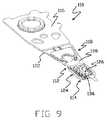
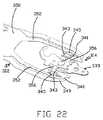
図20は、図19の図に対して、撓み部材312の反対の側の、スライダ332を有しない等角図である。図21〜図25は、撓み部材312及びDSA構造部314の等角図である。具体的には、図21〜図25は、撓み部材312及びDSA構造部314を含む種々の層を示している。図21は、図19の図であるが、補強材339がモータ334から取り外されている。図21に示されているように、モータ334は、モータ334の陽極及び陰極の端子を絶縁することができる、モータ334の非導電性セクション338を含む。図22は、図19の図であるが、タング333の詳細を更に示すためにモータ334が取り外されている。図22は一対の支柱356を示している。図22に示されているように、サスペンション310は、ステンレス鋼層340上にモータパッド341を含む。モータパッド341は粘弾性材料であるものとすることができ、タング333及び/又はモータ334に取着されるように更に接着性であってもよい。モータパッド341は防振可能である。モータパッド341又は他のダンパは、上記で本明細書に援用した、2012年10月10日に出願された米国仮特許出願第61/711,988号に記載されているように構成することができる。図22は、2片の接着剤343を更に示している。接着剤343は、エポキシ等の非導電性接着剤であるものとすることができる。図示のように、接着剤343の片は、ステンレス鋼層340のばねアーム352に配置される。接着剤343の片は、モータ334を一対のばねアーム352に取着することができる。図23は、図22の図であるが、ばねアーム352にそれぞれ位置決めされる導電性パッド347を露出させるために電気コネクタ345が取り外されている。電気コネクタ345は、はんだ、(例えば銀が充填された)導電性エポキシ、又は、電極の接続部を形成する他の材料を含むことができる。電気コネクタ345は、モータ334のそれぞれの陽極及び陰極の端子に電気的に接続することができる。導電性パッド347は誘電体層上に銅面を含むことができる。導電性パッド347は、モータ334の両端に印加される電気信号を制御するために可撓性回路349のそれぞれの回路に電気的に接続することができる。 FIG. 20 is an isometric view of the opposite side of the
図24は、図23の図であるが、モータパッド341及び接着剤343の片が取り外されている。図25はステンレス鋼層340のみを示している。図25に示されているように、ステンレス鋼層340は、ばねアーム352、支柱356及びタング333を形成する。一対の支柱356は、ばねアーム352間でタング333に接続するか又は別様に支持するステンレス鋼層340の唯一の部分である。具体的には、支柱356は、ばねアーム352とタング333との間の唯一の構造的な連結部であるものとすることができる。また、支柱356は、タング333に接続することによって、ベース部分350の遠位でばねアーム352間を接続するステンレス鋼層340の唯一の部分であるものとすることができる。図示のように、支柱356は、撓み部材312の長手方向軸に対して互いからずらされるか、又は、ばねアーム352に対してトラッキング軸を中心としたタング333の回転運動を提供するように別様に構成される。図22に最も良く示されているように、一対の支柱356のうちの一方の支柱356はモータ334の近位に位置し、一方で、一対の支柱356のうちの他方の支柱はモータ334の遠位に位置して、モータ334が一対の支柱356の間にあるようにする。各支柱356は、サスペンション310の長手方向軸に対して概ね垂直に延びる長手方向軸を有する。支柱356の長手方向軸は、平行に延び、支柱356が応力を受けていない(例えば曲がっていない)ときは互いに交差しないか又は別様に重ならない。図25に示されているように、支柱356は、それぞれ、X−Y平面においてステンレス鋼層340の最も狭い部分であるものとすることができ、一方で、ステンレス鋼層340の厚さは撓み部材312に沿って一貫しているものとすることができる。 FIG. 24 is a view of FIG. 23, with the
図26は、ジンバル324及びDSA構造部314を示す、サスペンション310の側面図である。図示のように、ディンプル336は、ロードビーム318のステンレス鋼に形成される構造であり、また、ロードビーム318から延びており、補強材339又は代替的にはモータ334に係合し、撓み部材312のベース部分350に対して面外でモータ334に接続されるジンバル324の部分を付勢することによって、荷重点として機能する。撓み部材312の曲がり又は遷移部が、ディンプル336によって、ジンバル324を付勢することに起因してばねアーム352に沿う任意の所望の位置に生じる。幾つかの実施形態では、モータ334は、タング333の反対側の横方向端部分の間の位置でタング333に構造的に取着される。そのような実施形態では、モータ334は、ばねアーム352に取着されることに加えて、タング333に取着される。幾つかの他の実施形態では、モータ334は、ばねアーム352に取着されるが、タング333には取着されないことで、モータ334がタング333に対して移動することを可能にする。 FIG. 26 is a side view of the
図27は、撓み部材312に取り付けられているモータ334の詳細図を示している。図示のように、電気コネクタ345は導電性パッド347に結合され、モータ334の上部に巻き付き、モータ334の端子と機械的及び電気的に接続する。図28は、モータ334の上部に巻き付く電気コネクタ345を更に示す撓み部材312の正面図を示している。図28に示されているように、補強材は上部層348及び底部層351を含む。上部層348は、ステンレス鋼等の金属材料の層を含むことができる。底部層351は接着剤を含むことができ、接着剤は、上部層348とモータ334の上面とを隔てるとともに結合する。 FIG. 27 shows a detailed view of the
DSA構造部314の動作については、図29A〜図29Cを参照して記載することができ、これらの図は、モータ334の起動又は非起動の幾つかの段階の間の撓み部材312の俯瞰図をそれぞれ示す。図29Bに示されているように、DSA構造部314及びタング333は、トラッキング駆動信号がモータ334に印加されないときは、タング333がばねアーム352間の概ね中央に位置する状態で、中立の駆動されない状態にある。図29Aに示されているように、第1の電位(例えばプラス)のトラッキング駆動信号がモータ334に印加されると、モータの形状が変化し、その長さが概ね広がる。この形状の変化によって、支柱356を含む連結部の機械的な作用と関連して、トラッキング軸を中心にばねアーム352に対してタング333を第1の方向に移動又は回転させる。図示のように、モータ334の延長によって、ジンバル324が横方向に伸張し、支柱356が曲がる(例えば内方に撓む)。支柱356のずれた配置によって、支柱356は、タング333が第1の方向に回転するように曲がる。 The operation of the
図29Cに示されているように、第2の電位(例えばマイナス)のトラッキング駆動信号がモータ334に適用されると、モータの形状が変化し、その長さが概ね収縮する。この形状の変化によって、連結支柱356の機械的な作用と関連して、トラッキング軸を中心にばねアーム352に対して、タング333を第2の方向に移動又は回転させる。第2の方向は第1の方向とは反対である。図示のように、モータ334の短縮によって、ジンバル324が横方向に圧縮され、支柱356が曲がる(例えば外方に撓む)。支柱356のずれた配置によって、支柱356は、タング333が第2の方向に回転するように曲がる。ジンバル324の他の部分の、比較的僅かであるが、幾らかの面外の動きを、上述したようなDSA構造部314のトラッキング作用の間に生成することができる。本発明のこの実施形態の場合、撓み部材のタング333のスライダ取付領域が、ばねアーム352が静止しているか又は僅かに移動するため、ばねアーム352に対して概ね回転する。 As shown in FIG. 29C, when a tracking drive signal having a second potential (for example, minus) is applied to the
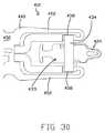
図30は、撓み部材412の俯瞰図を示している。撓み部材412は、図1〜図8Cのサスペンション10又は他のサスペンションにおいて具現することができる。撓み部材412は、別途記載又は示されるものを除いて、図1〜図8Cの撓み部材12と同様に構成することができる。図31A〜図31Cは、異なる移動状態で示されており、撓み部材412の更なる態様を明らかにするためにモータ434を有しない、撓み部材412のジンバル424のステンレス鋼側の俯瞰図である。撓み部材412は、ベース部分450、及び、ベース部分450から分岐するばねアーム452を含む。ばねアーム452は、モータ取付パッドとしてそれぞれ機能することができる支持領域458を含む。図30に示されているように、モータ434が撓み部材412に取り付けられる。具体的には、モータ434の反対側の長手方向端が支持領域458に取り付けられる。接着剤を用いて、本明細書において記載するようにモータ434を取り付けることができる。スライダ(図示せず)を、例えば図1〜図8Cの実施形態と同様に、本明細書において言及される任意の方法でタング433に取り付けることができる。例えば、スライダは、モータ434に対して、撓み部材412の反対側に位置することができる。 FIG. 30 shows an overhead view of the bending
図31Aに示されているように、タング433は、一対の支柱456によってばねアーム452(具体的には支持領域458)に接続される。タング433、支柱456、ばねアーム452及びベース部分450は、ステンレス鋼層440(又は他の種類の金属)から形成することができる。撓み部材412は、本明細書において説明される他のジンバルのように機能することができるジンバル424を含む。図1〜図8Cの撓み部材12は、互いに平行であるとともにモータ34の長手方向軸に平行なそれぞれの長手方向軸を有する支柱56を示しているが、撓み部材412の支柱456は、互いに対して平行であるがモータ434の長手方向軸に対しては平行ではないそれぞれの長手方向軸を有する。また別の実施形態では、撓み部材は、撓み部材の支柱の長手方向軸が互いに対して平行に延びず、また、支柱の長手方向軸がモータの長手方向軸に平行に延びないことを除いて、図31Aに示されているものと同様であるものとすることができる。図31Aの実施形態に戻ると、一対の支柱456は、ばねアーム452間でタング433を接続するか又は別様に構造的に支持するステンレス鋼層440の唯一の部分である。具体的には、支柱456は、ばねアーム452とタング433との間の唯一の構造的な連結部であるものとすることができる。また、支柱456は、タング433に接続することによって、ベース部分450の遠位でばねアーム452間を接続するステンレス鋼層440の唯一の部分であるものとすることができる。 As shown in FIG. 31A, the
撓み部材412のDSA構造部の動作を、図31A〜図31Cを参照して記載する。図31Aに示されているように、タング433は、トラッキング駆動信号がモータ434(図30に示されているが図31A〜図31Cには示されていない)に印加されないときは、タング433がばねアーム452間の概ね中央に位置する状態で、中立の駆動されない状態にある。第1の電位(例えばプラス)のトラッキング駆動信号がモータ434に印加されると、モータの形状が変化し、その長さが概ね広がる。この形状の変化によって、図31Bに示されているように支持領域458間の距離が増大し、これは、連結支柱456の機械的な作用と関連して、トラッキング軸を中心にばねアーム452に対して、タング433を第1の方向に移動又は回転させる。図示のように、モータ434の延長によって、ジンバル424が横方向に伸張し、支柱456が曲がる(例えば内方に撓む)。支柱456のずれた配置によって、支柱456は、タング433が第1の方向に回転するように曲がる。 The operation of the DSA structure portion of the bending
第2の電位(例えばマイナス)のトラッキング駆動信号がモータ434に印加されると、モータの形状が変化し、その長さが概ね収縮する。この形状の変化によって、図31Cに示されているように支持領域458間の距離が減少し、これは、連結支柱456の機械的な作用と関連して、トラッキング軸を中心にばねアーム452に対して、タング433を第2の方向に移動又は回転させる。第2の方向は第1の方向とは反対である。図示のように、モータ434の短縮によって、ジンバル424が横方向に圧縮され、支柱456が曲がる(例えば外方に撓む)。支柱456のずれた配置によって、支柱456は、タング433が第2の方向に回転するように曲がる。ジンバル424の他の部分の、比較的僅かであるが、幾らかの面外の動きが、上述したようなトラッキング作用の間に生成される。本発明のこの実施形態の場合、撓み部材のタング433のスライダ取付領域が、ばねアーム452が静止しているか又は僅かに移動するため、ばねアーム452に対して概ね回転する。 When a tracking drive signal having a second potential (for example, minus) is applied to the
なお、図1〜図31Cの実施形態は、単一のモータによって作動される種々のDSA構造部を示している。しかしながら、代替的に、本発明の態様を用いながら、種々の実施形態において複数のモータを用いることができる。 It should be noted that the embodiment of FIGS. 1-31C shows various DSA structures that are actuated by a single motor. However, alternatively, multiple motors can be used in various embodiments while using aspects of the present invention.
本発明の実施形態は重要な利点を提供する。例えば、幾つかの場合、サーボ帯域幅を大幅に高めることができる(例えばベースプレート又はロードビームベースのDSA構造部の約3〜4kHzから5〜8kHz以上に)。ストロークを増大させることができる。DSA構造部を効率的に製造することができる。 Embodiments of the present invention provide significant advantages. For example, in some cases, the servo bandwidth can be significantly increased (eg, from about 3-4 kHz to 5-8 kHz or more for a base plate or load beam based DSA structure). Stroke can be increased. The DSA structure can be efficiently manufactured.
本発明を、好ましい実施形態を参照して記載したが、当業者は、本発明の主旨及び範囲から逸脱することなく形態及び詳細に変更を加えることができることを認識するであろう。本発明の範囲から逸脱することなく、種々の変更及び付加を説明した例示的な実施形態に加えることができる。例えば、上述した実施形態は特定の特徴に言及しているが、本発明の範囲は、特徴の異なる組み合わせを有する実施形態、及び、上述した特徴の全ては含まない実施形態も含む。 Although the present invention has been described with reference to preferred embodiments, workers skilled in the art will recognize that changes may be made in form and detail without departing from the spirit and scope of the invention. Various changes and additions can be made to the described exemplary embodiments without departing from the scope of the present invention. For example, although the embodiments described above refer to particular features, the scope of the present invention includes embodiments having different combinations of features and embodiments that do not include all of the features described above.
Claims (22)
Translated fromJapanese一対のばねアームと、
前記一対のばねアーム間に位置するとともに前記一対のばねアームによって構造的に支持されるタングと、
一対の支柱であって、前記一対のばねアームと前記タングとの間にそれぞれ位置決めされ、各支柱は、前記タングの遠位部分及び近位部分が、前記一対の支柱を越えて前記タングの長手方向軸に沿って反対方向に延びるように、前記一対のばねアームのそれぞれから前記タングに向かって内方に延びることによって、前記一対のばねアームのそれぞれを前記タングに対して接続し、各支柱は、各長手方向軸に沿って伸長し、前記一対の支柱の長手方向軸は互いに対して平行であるとともにずれている、一対の支柱と、を備える、撓み部材、
スライダ取付部、並びに
前記撓み部材に取り付けられるモータであって、前記一対の支柱の長手方向軸に平行な長手方向軸を有し、前記モータの電気的起動によって前記一対の支柱が曲がり、トラッキング軸を中心に前記タング及び前記スライダ取付部を回転させる、モータ、
を備える、ジンバル形撓み部材。A gimbal-shaped flexible member having a two-stage starting (DSA) structure,
A pair of spring arms;
A tongue positioned between the pair of spring arms and structurally supported by the pair of spring arms;
A pair of struts, each positioned between the pair of spring arms and the tongue, each strut havinga distal portion and a proximal portion of the tongue beyond the pair of struts and the length of the tongue Each of the pair of spring arms is connected to the tongue by extending inwardly toward the tongue from each of the pair of spring arms so as to extend in opposite directions along a directional axis, and A pair of strutsextending alongeach longitudinal axis, the longitudinal axesof the pair of struts being parallel to and offset from each other,
Slider mounting portion, and a motor attached to the flexible member, the pair of having a longitudinal axis parallel to thelongitudinal axis of the post, the pair of struts to bend by electrical activation of the motor, tracking shaft A motor thatrotates thetongue and the slider mounting portion about
A gimbal-shaped flexible member.
金属の層を含む撓み部材であって、前記金属の層は、
一対のばねアームと、
前記ばねアーム間に位置するタングと、
一対の支柱であって、前記一対のばねアームを前記タングにそれぞれ接続し、前記タングの遠位部分及び近位部分が前記一対の支柱を越えて前記タングの長手方向軸に沿って反対方向に延びるように、前記一対のばねアームを前記タングに対して接続する前記金属の層の唯一の部分である、一対の支柱と、を画定する、撓み部材、
前記タングのスライダ取付部、並びに
前記一対のばねアームにそれぞれ取付られる両端を有するモータであって、該モータの電気的起動によって前記一対の支柱が曲がり、前記スライダ取付部を、トラッキング軸を中心に回転させる、モータ、
を備える、ジンバル形撓み部材。A gimbal-shaped flexible member having a two-stage starting (DSA) structure,
A flexible member comprising a metal layer, wherein the metal layer comprises:
A pair of spring arms;
A tongue located between the spring arms;
A pair of struts, each connecting the pair of spring armsto the tongue,the distal and proximal portions of the tongue over the pair of struts in opposite directions along the longitudinal axis of the tongue A flexure member thatdefines a pair of strutsthat are only a portion of the metal layer that connects the pair of spring arms to the tongue to extend .
A motor having both ends attached to the slider mounting portion of the tongue and the pair of spring arms, the pair of struts being bent by electrical activation of the motor, and the slider mounting portion is centered on the tracking axis;Rotate , motor,
A gimbal-shaped flexible member.
少なくとも1つの2段始動構造部を有する近位取付構造部、並びに A proximal mounting structure having at least one two-stage starting structure; and
前記近位取付構造部と連結された撓み部材であって、 A deflecting member coupled to the proximal mounting structure,
一対のばねアームと、 A pair of spring arms;
前記ばねアーム間に位置するタングと、 A tongue located between the spring arms;
一対の支柱であって、前記タングの遠位部分及び近位部分が、前記一対の支柱を越えて前記タングの長手方向軸に沿って反対方向に延びるように、前記一対のばねアームを前記タングに対して接続するようにそれぞれ構成された、一対の支柱と、 A pair of struts, wherein the pair of spring arms are configured to extend in opposite directions along the longitudinal axis of the tongue beyond the pair of struts. A pair of struts, each configured to connect to,
前記タングのスライダ取付部と、 A slider mounting portion of the tongue;
一対のモータ取付パッドであって、前記一対のモータ取付パッドにそれぞれ取り付けられた両端を有するモータを取り付けるように構成されており、前記一対のモータ取付パッドのそれぞれが前記一対のばねアームのそれぞれに位置する、一対のモータ取付パッドと、を含む、撓み部材、 A pair of motor mounting pads, each of which is configured to mount a motor having both ends attached to the pair of motor mounting pads, and each of the pair of motor mounting pads is attached to each of the pair of spring arms. A pair of motor mounting pads located, including a flexure member,
を備える、サスペンション。A suspension comprising:
Applications Claiming Priority (3)
| Application Number | Priority Date | Filing Date | Title |
|---|---|---|---|
| US201261700972P | 2012-09-14 | 2012-09-14 | |
| US61/700,972 | 2012-09-14 | ||
| PCT/US2013/059702WO2014043498A2 (en) | 2012-09-14 | 2013-09-13 | Co-located gimbal-based dual stage actuation disk drive suspensions |
Publications (3)
| Publication Number | Publication Date |
|---|---|
| JP2015531956A JP2015531956A (en) | 2015-11-05 |
| JP2015531956A5 JP2015531956A5 (en) | 2016-10-27 |
| JP6251745B2true JP6251745B2 (en) | 2017-12-20 |
Family
ID=50274222
Family Applications (1)
| Application Number | Title | Priority Date | Filing Date |
|---|---|---|---|
| JP2015532087AActiveJP6251745B2 (en) | 2012-09-14 | 2013-09-13 | Gimbal-type flexible member having two-stage starting structure and suspension |
Country Status (3)
| Country | Link |
|---|---|
| US (2) | US8681456B1 (en) |
| JP (1) | JP6251745B2 (en) |
| WO (1) | WO2014043498A2 (en) |
Families Citing this family (39)
| Publication number | Priority date | Publication date | Assignee | Title |
|---|---|---|---|---|
| US8885299B1 (en) | 2010-05-24 | 2014-11-11 | Hutchinson Technology Incorporated | Low resistance ground joints for dual stage actuation disk drive suspensions |
| US9190086B1 (en)* | 2011-11-30 | 2015-11-17 | Magnecomp Corporation | GSA suspension having slider clearance for shock performance |
| US8879210B1 (en)* | 2011-11-30 | 2014-11-04 | Magnecomp Corporation | DSA suspension with microactuators extending to gimbal through flexible connectors |
| WO2013138619A1 (en) | 2012-03-16 | 2013-09-19 | Hutchinson Technology Incorporated | Mid-loadbeam dual stage actuated (dsa) disk drive head suspension |
| DE102012023275A1 (en)* | 2012-07-12 | 2014-01-16 | Olympus Winter & Ibe Gmbh | resectoscope |
| JP6251745B2 (en) | 2012-09-14 | 2017-12-20 | ハッチンソン テクノロジー インコーポレイテッドHutchinson Technology Incorporated | Gimbal-type flexible member having two-stage starting structure and suspension |
| JP5933403B2 (en)* | 2012-09-27 | 2016-06-08 | 日本発條株式会社 | Suspension for disk unit |
| JP5933402B2 (en)* | 2012-09-27 | 2016-06-08 | 日本発條株式会社 | Suspension for disk unit |
| WO2014059128A2 (en) | 2012-10-10 | 2014-04-17 | Hutchinson Technology Incorporated | Co-located gimbal-based dual stage actuation disk drive suspensions with dampers |
| US8941951B2 (en) | 2012-11-28 | 2015-01-27 | Hutchinson Technology Incorporated | Head suspension flexure with integrated strain sensor and sputtered traces |
| US8891206B2 (en) | 2012-12-17 | 2014-11-18 | Hutchinson Technology Incorporated | Co-located gimbal-based dual stage actuation disk drive suspensions with motor stiffener |
| US9330694B1 (en) | 2013-03-18 | 2016-05-03 | Magnecomp Corporation | HDD microactuator having reverse poling and active restraining layer |
| US9070394B1 (en) | 2013-03-18 | 2015-06-30 | Magnecomp Corporation | Suspension microactuator with wrap-around electrode on inactive constraining layer |
| US9741376B1 (en) | 2013-03-18 | 2017-08-22 | Magnecomp Corporation | Multi-layer PZT microactuator having a poled but inactive PZT constraining layer |
| US10607642B2 (en) | 2013-03-18 | 2020-03-31 | Magnecomp Corporation | Multi-layer PZT microactuator with active PZT constraining layers for a DSA suspension |
| US9117468B1 (en) | 2013-03-18 | 2015-08-25 | Magnecomp Corporation | Hard drive suspension microactuator with restraining layer for control of bending |
| US11205449B2 (en) | 2013-03-18 | 2021-12-21 | Magnecomp Corporation | Multi-layer PZT microacuator with active PZT constraining layers for a DSA suspension |
| US9330698B1 (en) | 2013-03-18 | 2016-05-03 | Magnecomp Corporation | DSA suspension having multi-layer PZT microactuator with active PZT constraining layers |
| US8896969B1 (en) | 2013-05-23 | 2014-11-25 | Hutchinson Technology Incorporated | Two-motor co-located gimbal-based dual stage actuation disk drive suspensions with motor stiffeners |
| US8717712B1 (en) | 2013-07-15 | 2014-05-06 | Hutchinson Technology Incorporated | Disk drive suspension assembly having a partially flangeless load point dimple |
| US9330697B2 (en) | 2013-12-05 | 2016-05-03 | Hutchinson Technology Incorporated | Constrained dimple pad damper for disk drive head suspension |
| US8896970B1 (en) | 2013-12-31 | 2014-11-25 | Hutchinson Technology Incorporated | Balanced co-located gimbal-based dual stage actuation disk drive suspensions |
| US8867173B1 (en) | 2014-01-03 | 2014-10-21 | Hutchinson Technology Incorporated | Balanced multi-trace transmission in a hard disk drive flexure |
| US8834660B1 (en) | 2014-01-07 | 2014-09-16 | Hutchinson Technology Incorporated | Visco pad placement in disk drives |
| US8928335B1 (en) | 2014-01-24 | 2015-01-06 | Hutchinson Technology Incorporated | Stepped impedance flexure design in a hard disk drive |
| US9214176B1 (en)* | 2014-08-08 | 2015-12-15 | Magnecomp Corporation | PZT limiter for a micro dual stage actuated suspension |
| US9070392B1 (en) | 2014-12-16 | 2015-06-30 | Hutchinson Technology Incorporated | Piezoelectric disk drive suspension motors having plated stiffeners |
| US9318136B1 (en) | 2014-12-22 | 2016-04-19 | Hutchinson Technology Incorporated | Multilayer disk drive motors having out-of-plane bending |
| US9296188B1 (en) | 2015-02-17 | 2016-03-29 | Hutchinson Technology Incorporated | Partial curing of a microactuator mounting adhesive in a disk drive suspension |
| US10128431B1 (en) | 2015-06-20 | 2018-11-13 | Magnecomp Corporation | Method of manufacturing a multi-layer PZT microactuator using wafer-level processing |
| CN107735834B (en) | 2015-06-30 | 2019-11-19 | 哈钦森技术股份有限公司 | Disk drive head suspension structure with improved reliability |
| US9892748B1 (en)* | 2015-12-29 | 2018-02-13 | Magnecomp Corporation | Head suspension assembly having PZT damper with non-uniform thickness |
| US9646638B1 (en) | 2016-05-12 | 2017-05-09 | Hutchinson Technology Incorporated | Co-located gimbal-based DSA disk drive suspension with traces routed around slider pad |
| US10373634B2 (en) | 2016-06-30 | 2019-08-06 | Hutchinson Technology Incorporated | Co-located gimbal-based dual stage actuation disk drive head suspension with non-parallel motors |
| US11056138B2 (en) | 2018-03-20 | 2021-07-06 | Magnecomp Corporation | Disk drive suspension tri-stage actuator with single side actuator attach |
| US10783909B1 (en) | 2018-05-14 | 2020-09-22 | Seagate Technology | In-plane gimbal tongue microactuator system |
| US10650851B1 (en)* | 2019-01-31 | 2020-05-12 | Seagate Technology Llc | Data storage device suspension strut damping system |
| US11037589B1 (en)* | 2020-05-29 | 2021-06-15 | Seagate Technology Llc | Multi-piece head gimbal assembly |
| US11393497B2 (en) | 2020-11-04 | 2022-07-19 | Western Digital Technologies, Inc. | Restriction of suspension dimple contact point |
Family Cites Families (324)
| Publication number | Priority date | Publication date | Assignee | Title |
|---|---|---|---|---|
| US3320556A (en) | 1963-05-23 | 1967-05-16 | Bell Telephone Labor Inc | Impedance transformer |
| DE3020371C2 (en) | 1980-05-29 | 1985-12-19 | Degussa Ag, 6000 Frankfurt | Process for the pretreatment of stainless steel for direct galvanic gold plating |
| US4418239A (en) | 1981-08-24 | 1983-11-29 | Oak Industries Inc. | Flexible connector with interconnection between conductive traces |
| US4422906A (en) | 1981-09-17 | 1983-12-27 | Masami Kobayashi | Process for direct gold plating of stainless steel |
| US6600631B1 (en) | 1989-11-27 | 2003-07-29 | Censtor Corp. | Transducer/flexure/conductor structure for electromagnetic read/write system |
| US5333085A (en) | 1990-11-06 | 1994-07-26 | Seagate Technology, Inc. | Read/write gimbal with limited range of motion |
| US5140288A (en) | 1991-04-08 | 1992-08-18 | Motorola, Inc. | Wide band transmission line impedance matching transformer |
| US5427848A (en) | 1991-05-06 | 1995-06-27 | International Business Machines Corporation | Stress balanced composite laminate material |
| US5764444A (en) | 1991-07-23 | 1998-06-09 | Fujitsu Limited | Mechanism for minute movement of a head |
| WO1993014495A1 (en) | 1992-01-20 | 1993-07-22 | Fujitsu Limited | Magnetic head assembly, its manufacture, and magnetic disc device |
| US5282103A (en) | 1992-10-07 | 1994-01-25 | Read-Rite Corporation | Magnetic head suspension assembly fabricated with integral load beam and flexure |
| US5334804A (en) | 1992-11-17 | 1994-08-02 | Fujitsu Limited | Wire interconnect structures for connecting an integrated circuit to a substrate |
| US5320272A (en) | 1993-04-02 | 1994-06-14 | Motorola, Inc. | Tin-bismuth solder connection having improved high temperature properties, and process for forming same |
| US5321568A (en) | 1993-04-22 | 1994-06-14 | Maxtor Corporation | Head suspension assembly with improved pitch and roll characteristics |
| US5485053A (en) | 1993-10-15 | 1996-01-16 | Univ America Catholic | Method and device for active constrained layer damping for vibration and sound control |
| US5459921A (en) | 1993-11-12 | 1995-10-24 | Seagate Technology, Inc. | Method of making a disc drive actuator arm with arm compliance compensation |
| US5491597A (en) | 1994-04-15 | 1996-02-13 | Hutchinson Technology Incorporated | Gimbal flexure and electrical interconnect assembly |
| US5598307A (en) | 1994-04-15 | 1997-01-28 | Hutchinson Technology Inc. | Integrated gimbal suspension assembly |
| US5631786A (en) | 1994-05-19 | 1997-05-20 | International Business Machines Corporation | Termination pad manipulator for a laminated suspension in a data storage system |
| US5608590A (en) | 1994-06-20 | 1997-03-04 | Hutchinson Technology Incorporated | Gimballing flexure with static compensation and load print intregal etched features |
| US6539609B2 (en) | 1994-07-05 | 2003-04-01 | International Business Machines Corporation | Method of forming a head gimbal assembly |
| JP3354302B2 (en) | 1994-07-27 | 2002-12-09 | 日本メクトロン株式会社 | Manufacturing method of suspension for magnetic head |
| US5521778A (en) | 1994-08-30 | 1996-05-28 | International Business Machines Corporation | Disk drive with primary and secondary actuator drives |
| JPH08111015A (en) | 1994-09-01 | 1996-04-30 | Tdk Corp | Supporting device of magnetic head slider and magnetic head device |
| US5657188A (en) | 1995-06-01 | 1997-08-12 | Hutchinson Technology Incorporated | Head suspension with tracking microactuator |
| US5608591A (en) | 1995-06-09 | 1997-03-04 | International Business Machines Corporation | Integrated head-electronics interconnection suspension for a data recording disk drive |
| JPH0922570A (en) | 1995-07-03 | 1997-01-21 | Fujitsu Ltd | Head assembly and magnetic disk device including the head assembly |
| US5666241A (en) | 1995-07-10 | 1997-09-09 | Magnecomp Corp. | Double dimple disk drive suspension |
| US5674970A (en) | 1995-07-12 | 1997-10-07 | Georgia-Pacific Resins, Inc. | Phenolic polymers made by aralkylation reactions |
| US5636089A (en) | 1995-08-01 | 1997-06-03 | Hutchinson Technology Incorporated | Head suspension with spaced static attitude compensation protuberance and load dimple |
| SG43433A1 (en) | 1995-10-27 | 1997-10-17 | Tdk Corp | Suspension slider-suspension assmebly assembly carriage device and manufacturing method of the suspension |
| US5737152A (en) | 1995-10-27 | 1998-04-07 | Quantum Corporation | Suspension with multi-layered integrated conductor trace array for optimized electrical parameters |
| US6284563B1 (en) | 1995-10-31 | 2001-09-04 | Tessera, Inc. | Method of making compliant microelectronic assemblies |
| US6215622B1 (en) | 1996-01-02 | 2001-04-10 | International Business Machines Corporation | Laminated hard disk head suspension and etching process |
| US5892637A (en) | 1996-05-10 | 1999-04-06 | International Business Machines Corporation | Multi-piece integrated suspension assembly for a magnetic storage system |
| JPH103632A (en) | 1996-06-12 | 1998-01-06 | Dainippon Printing Co Ltd | Magnetic head suspension |
| US5914834A (en) | 1996-06-17 | 1999-06-22 | Hutchinson Technology, Inc. | Head suspension assembly with electrical interconnect by slider bond pads and gimbal bonding zones |
| US5805382A (en) | 1996-06-21 | 1998-09-08 | International Business Machines Corporation | Integrated conductor magnetic recording head and suspension having cross-over integrated circuits for noise reduction |
| US6078470A (en) | 1996-06-28 | 2000-06-20 | Hutchinson Technology, Inc. | Head suspension having a modified dimple design |
| US5921131A (en) | 1996-06-28 | 1999-07-13 | Hutchinson Technology Incorporated | Method for frictionally guiding and forming ferrous metal |
| US5818662A (en) | 1996-07-15 | 1998-10-06 | International Business Machines Corporation | Static attitude and stiffness control for an integrated suspension |
| US5973882A (en) | 1996-08-07 | 1999-10-26 | Hutchinson Technology, Inc. | Moment-flex head suspension |
| US6307715B1 (en) | 1996-08-30 | 2001-10-23 | Read-Rite Corporation | Head suspension having reduced torsional vibration |
| US6362936B2 (en) | 1996-09-26 | 2002-03-26 | International Business Machines Corporation | Suspension assembly with integral projections having a coating of elastic material |
| US5995328A (en) | 1996-10-03 | 1999-11-30 | Quantum Corporation | Multi-layered integrated conductor trace array interconnect structure having optimized electrical parameters |
| US5796552A (en) | 1996-10-03 | 1998-08-18 | Quantum Corporation | Suspension with biaxially shielded conductor trace array |
| US5717547A (en) | 1996-10-03 | 1998-02-10 | Quantum Corporation | Multi-trace transmission lines for R/W head interconnect in hard disk drive |
| US6246552B1 (en) | 1996-10-31 | 2001-06-12 | Tdk Corporation | Read/write head including displacement generating means that elongates and contracts by inverse piezoelectric effect of electrostrictive effect |
| WO1998020485A1 (en) | 1996-11-06 | 1998-05-14 | Quantum Corporation | Head suspension with self-shielding 'twisted' integrated conductor trace array |
| US6108175A (en)* | 1996-12-16 | 2000-08-22 | Seagate Technology, Inc. | Bimorph piezoelectric microactuator head and flexure assembly |
| US5790347A (en) | 1996-12-23 | 1998-08-04 | Hutchinson Technology Incorporated | Head suspension load beam and flexure construction for reducing structural height |
| US5734526A (en) | 1996-12-31 | 1998-03-31 | Hutchinson Technology Incorporated | Monocoque head suspension and its method of construction |
| US6038102A (en) | 1997-01-21 | 2000-03-14 | Quantum Corporation | Conductor trace array having interleaved passive conductors |
| US6275358B1 (en) | 1997-01-21 | 2001-08-14 | Maxtor Corporation | Conductor trace array having passive stub conductors |
| US6349017B1 (en) | 1997-02-21 | 2002-02-19 | Read-Rite Corporation | Magnetic head suspension assembly using bonding pads of a slider to an attachment surface of a flexure |
| US6011671A (en) | 1997-04-10 | 2000-01-04 | Seagate Technology, Inc. | Head gimbal assembly for limiting dimple separation for a data storage device |
| US5812344A (en) | 1997-05-12 | 1998-09-22 | Quantum Corporation | Suspension with integrated conductor trace array having optimized cross-sectional high frequency current density |
| JP3495224B2 (en) | 1997-06-06 | 2004-02-09 | アルプス電気株式会社 | Magnetic head device and method of manufacturing the same |
| US5898544A (en) | 1997-06-13 | 1999-04-27 | Hutchinson Technology Incorporated | Base plate-mounted microactuator for a suspension |
| US6396667B1 (en)* | 1997-06-24 | 2002-05-28 | Seagate Technology Llc | Electromagnetic disc drive microactuator and suspension |
| US6728077B1 (en)* | 1997-07-03 | 2004-04-27 | Seagate Technology Llc | Suspension-level piezoelectric microactuator |
| US5862010A (en) | 1997-07-08 | 1999-01-19 | International Business Machines Corporation | Transducer suspension system |
| JP3605497B2 (en) | 1997-07-11 | 2004-12-22 | 日本発条株式会社 | Suspension for disk drive |
| US5973884A (en) | 1997-07-21 | 1999-10-26 | K. R. Precision Public Company Limited | Gimbal assembly with offset slider pad and cross beam for pitch and roll stiffness and high vertical and horizontal stiffness |
| US6246546B1 (en) | 1997-10-02 | 2001-06-12 | Hutchinson Technology Incorporated | Coined partial etched dimple in a head suspension and method of manufacture |
| US6195227B1 (en) | 1997-12-30 | 2001-02-27 | International Business Machines, Inc. | Integrated 3D limiters for microactuators |
| US6262868B1 (en) | 1997-12-30 | 2001-07-17 | International Business Machines Corporation | Method and structures used for connecting recording head signal wires in a microactuator |
| US5924187A (en) | 1998-01-06 | 1999-07-20 | Hutchinson Technology Incorporated | Integrated lead head suspension assembly having an etched laminated load beam and flexure with deposited conductors |
| US6118637A (en) | 1998-01-08 | 2000-09-12 | Seagate Technology, Inc. | Piezoelectric assembly for micropositioning a disc drive head |
| JP3257500B2 (en) | 1998-02-27 | 2002-02-18 | ティーディーケイ株式会社 | Magnetic head device |
| US6157522A (en) | 1998-04-07 | 2000-12-05 | Seagate Technology Llc | Suspension-level microactuator |
| US6295185B1 (en) | 1998-04-07 | 2001-09-25 | Seagate Technology Llc | Disc drive suspension having a moving coil or moving magnet microactuator |
| JP3923174B2 (en) | 1998-04-28 | 2007-05-30 | 富士通株式会社 | Head assembly and suspension |
| US6735055B1 (en)* | 1998-05-07 | 2004-05-11 | Seagate Technology Llc | Microactuator structure with vibration attenuation properties |
| US6055132A (en) | 1998-06-04 | 2000-04-25 | Internatinal Business Machines Corporation | Integrated lead suspension flexure for attaching a micro-actuator with a transducer slider |
| US6282063B1 (en) | 1998-06-09 | 2001-08-28 | Magnecomp Corp. | Flexure-slider bonding system |
| US6400532B1 (en) | 1998-06-17 | 2002-06-04 | Magnecomp Corp. | Recording head suspension with coupled dimple and channel |
| US6320730B1 (en)* | 1998-09-26 | 2001-11-20 | Seagate Technology Llc | Low-stress disc drive microactuator cradle |
| US6297936B1 (en)* | 1998-11-09 | 2001-10-02 | Seagate Technology Llc | Integral load beam push-pull microactuator |
| JP3501758B2 (en)* | 1998-11-13 | 2004-03-02 | Tdk株式会社 | Recording / reproducing head support mechanism and recording / reproducing apparatus |
| JP2001084723A (en)* | 1998-11-13 | 2001-03-30 | Tdk Corp | Recording/reproducing head support mechanism and recording/reproducing apparatus |
| US6233124B1 (en) | 1998-11-18 | 2001-05-15 | Seagate Technology Llc | Piezoelectric microactuator suspension assembly with improved stroke length |
| US6714384B2 (en) | 1998-12-07 | 2004-03-30 | Seagate Technology Llc | Reduced stiffness printed circuit head interconnect |
| US6146813A (en) | 1999-01-13 | 2000-11-14 | Applied Kinetics Inc. | Method and shunting and deshunting an electrical component and a shuntable/shunted electrical component |
| US6249404B1 (en) | 1999-02-04 | 2001-06-19 | Read-Rite Corporation | Head gimbal assembly with a flexible printed circuit having a serpentine substrate |
| US6596184B1 (en) | 1999-02-15 | 2003-07-22 | International Business Machines Corporation | Non-homogeneous laminate materials for suspensions with conductor support blocks |
| JP3532439B2 (en) | 1999-03-02 | 2004-05-31 | アルプス電気株式会社 | Magnetic head |
| JP3725991B2 (en) | 1999-03-12 | 2005-12-14 | 株式会社日立グローバルストレージテクノロジーズ | Magnetic disk unit |
| US6300846B1 (en) | 1999-03-18 | 2001-10-09 | Molex Incorporated | Flat flexible cable with ground conductors |
| US6320729B1 (en) | 1999-04-27 | 2001-11-20 | Magnecomp Corp. | Snap-in assembly of suspension limiter having both high shock and load/unload cycle capability |
| US6278587B1 (en) | 1999-04-21 | 2001-08-21 | Magnecomp Corp. | Positive coupling of piezoelectric devices in disk drive suspensions |
| US6469870B1 (en) | 1999-04-28 | 2002-10-22 | Magnecomp Corporation | Slider location in head gimbal assemblies using indicia instead of dimple |
| US6172853B1 (en) | 1999-05-20 | 2001-01-09 | Hutchinson Technology Incorporated | Head suspension having a near dimple motion limiter |
| US6501625B1 (en) | 1999-06-29 | 2002-12-31 | Hutchinson Technology Incorporated | Disk drive suspension with multi-layered piezoelectric actuator controlled gram load |
| WO2001006146A1 (en) | 1999-07-14 | 2001-01-25 | Material Sciences Corporation | Vibration isolating construction |
| JP2001043647A (en) | 1999-07-15 | 2001-02-16 | Internatl Business Mach Corp <Ibm> | Hard disk drive, slider holding structure, head gimbals assembly and its manufacture |
| JP3759344B2 (en) | 1999-08-02 | 2006-03-22 | アルプス電気株式会社 | Magnetic head and method of manufacturing magnetic head |
| JP2001057039A (en) | 1999-08-13 | 2001-02-27 | Sony Corp | Head suspension, head gimbals assembly and actuator |
| US6156982A (en) | 1999-09-24 | 2000-12-05 | Honeywell Inc. | Low current high temperature switch contacts |
| US6563676B1 (en) | 1999-09-28 | 2003-05-13 | Maxtor Corporation | Disk drive actuator arm |
| US6239953B1 (en) | 1999-10-15 | 2001-05-29 | Magnecomp Corp. | Microactuated disk drive suspension with heightened stroke sensitivity |
| JP4356215B2 (en) | 1999-11-10 | 2009-11-04 | 凸版印刷株式会社 | Flexure, manufacturing method thereof, and flexure substrate used therefor |
| JP2001209918A (en) | 1999-11-19 | 2001-08-03 | Nitto Denko Corp | Suspension board with circuit |
| US6639761B1 (en) | 1999-12-02 | 2003-10-28 | Seagate Technology Llc | Micro-actuator damping and humidity protection |
| US6661617B1 (en) | 1999-12-14 | 2003-12-09 | Seagate Technology Llc | Structure and fabrication process for integrated moving-coil magnetic micro-actuator |
| US6549736B2 (en) | 2000-01-19 | 2003-04-15 | Canon Kabushiki Kaisha | Process cartridge, engaging member therefor and method for mounting developing roller and magnet |
| JP3716164B2 (en) | 2000-02-14 | 2005-11-16 | 株式会社日立グローバルストレージテクノロジーズ | Head support mechanism |
| US6614627B1 (en) | 2000-02-14 | 2003-09-02 | Hitachi, Ltd. | Magnetic disk apparatus |
| JP3611198B2 (en) | 2000-02-16 | 2005-01-19 | 松下電器産業株式会社 | Actuator and information recording / reproducing apparatus using the same |
| US6900967B1 (en) | 2000-02-24 | 2005-05-31 | Magnecomp Corporation | Trace flexure suspension with differential insulator and trace structures for locally tailoring impedance |
| US6414820B1 (en) | 2000-02-24 | 2002-07-02 | Magnecomp Corporation | Trace flexure suspension with differential impedance in read and write conductor circuits |
| US7382582B1 (en) | 2000-03-21 | 2008-06-03 | Magnecomp Corporation | Reduced cross talk in wireless suspensions |
| US6647621B1 (en) | 2000-03-24 | 2003-11-18 | Hutchinson Technology Incorporated | Electrical resistance reduction method for thermosetting conductive epoxy contacts in integrated lead suspensions |
| US6942817B2 (en) | 2000-03-24 | 2005-09-13 | Dainippon Printing Co., Ltd. | Method of manufacturing wireless suspension blank |
| US6549376B1 (en) | 2000-03-31 | 2003-04-15 | John E. Scura | Gimbal suspension with vibration damper |
| JP4104807B2 (en) | 2000-04-13 | 2008-06-18 | 日本発条株式会社 | Suspension for disk unit |
| US6704157B2 (en) | 2000-04-14 | 2004-03-09 | Seagate Technology Llc | Passive damping method and circuit for data storage device actuator |
| US6480359B1 (en) | 2000-05-09 | 2002-11-12 | 3M Innovative Properties Company | Hard disk drive suspension with integral flexible circuit |
| US6728057B2 (en) | 2000-05-10 | 2004-04-27 | Seagate Technology Llc | Frequency extension method and apparatus for fast rise time writers |
| JP4156203B2 (en) | 2000-05-22 | 2008-09-24 | 株式会社日立グローバルストレージテクノロジーズ | Suspension for disk unit |
| US6621653B1 (en) | 2000-06-09 | 2003-09-16 | Hitachi Global Storage Technologies Netherlands B.V. | Secondary actuator system for mode compensation |
| WO2001099104A2 (en)* | 2000-06-20 | 2001-12-27 | Seagate Technology Llc | Head pitch adjustment for disc drive |
| US6493190B1 (en) | 2000-08-16 | 2002-12-10 | Magnecomp Corporation | Trace flexure with controlled impedance |
| US7256968B1 (en) | 2000-09-11 | 2007-08-14 | Hutchinson Technology Incorporated | Microactuated dimple for head suspensions |
| JP2002093093A (en) | 2000-09-19 | 2002-03-29 | Tdk Corp | Head gimbals assembly |
| CN1937037A (en) | 2000-11-28 | 2007-03-28 | 新科实业有限公司 | Magnetic head spring leaf assembly with piezoelectric micro-actuation mechanism |
| JP2002170607A (en) | 2000-12-01 | 2002-06-14 | Fujikura Ltd | Jumper parts, jumper structure and short-circuit method of flexible printed circuit |
| US7177119B1 (en) | 2000-12-05 | 2007-02-13 | Hutchinson Technology Incorporated | Microactuated head suspension with ring springs |
| JP4298911B2 (en) | 2000-12-15 | 2009-07-22 | 日本発條株式会社 | Suspension for disk unit |
| JP4237394B2 (en) | 2000-12-27 | 2009-03-11 | 日本発條株式会社 | Suspension for disk unit |
| US6798597B1 (en) | 2001-02-02 | 2004-09-28 | Marvell International Ltd. | Write channel having preamplifier and non-uniform transmission line |
| US6490228B2 (en) | 2001-02-16 | 2002-12-03 | Koninklijke Philips Electronics N.V. | Apparatus and method of forming electrical connections to an acoustic transducer |
| US6760182B2 (en) | 2001-02-19 | 2004-07-06 | Seagate Technology Llc | Temperature compensated fly height control |
| JP3792521B2 (en) | 2001-02-23 | 2006-07-05 | アルプス電気株式会社 | Magnetic head device |
| JP2002269713A (en) | 2001-03-12 | 2002-09-20 | Tdk Corp | Method for machining head suspension |
| US6714385B1 (en) | 2001-04-16 | 2004-03-30 | Hutchinson Technology Inc. | Apparatus and method for controlling common mode impedance in disk drive head suspensions |
| US6977790B1 (en) | 2001-05-04 | 2005-12-20 | Maxtor Corporation | Design scheme to increase the gain of strain based sensors in hard disk drive actuators |
| JP2003059219A (en)* | 2001-05-16 | 2003-02-28 | Read Rite Corp | Micro-actuator, read/write head, head gimbal assembly, actuator arm for disk drive, and the disk drive |
| US6376964B1 (en) | 2001-05-16 | 2002-04-23 | Read-Rite Corporation | Collocated rotating flexure microactuator for dual-stage servo in disk drives |
| US6760196B1 (en)* | 2001-12-12 | 2004-07-06 | Western Digital, Inc. | Microactuator with offsetting hinges and method for high-resolution positioning of magnetic read/write head |
| US6704158B2 (en) | 2001-06-05 | 2004-03-09 | Western Digital (Fremont), Inc. | Shear mode multilayered collocated micro-actuator for dual-stage servo controllers in disk drives |
| US6898042B2 (en)* | 2001-05-23 | 2005-05-24 | Seagate Technology Llc | Slider level microactuator with integrated fly control |
| US6856075B1 (en) | 2001-06-22 | 2005-02-15 | Hutchinson Technology Incorporated | Enhancements for adhesive attachment of piezoelectric motor elements to a disk drive suspension |
| US7006333B1 (en)* | 2001-06-28 | 2006-02-28 | Magnecomp Corporation | Suspension with flexure mounted microactuator |
| JP4144198B2 (en) | 2001-07-04 | 2008-09-03 | 新科實業有限公司 | Vibration suppression mechanism and head gimbal assembly with vibration suppression mechanism |
| JP4144197B2 (en) | 2001-07-04 | 2008-09-03 | 新科實業有限公司 | Vibration suppression mechanism and head gimbal assembly with vibration suppression mechanism |
| JP4144196B2 (en) | 2001-07-04 | 2008-09-03 | 新科實業有限公司 | Vibration suppression mechanism and head gimbal assembly with vibration suppression mechanism |
| US6967821B2 (en) | 2001-07-10 | 2005-11-22 | Seagate Technology Llc | Head gimbal assembly including dampening for air bearing vibration |
| JP4144199B2 (en) | 2001-07-13 | 2008-09-03 | 新科實業有限公司 | Vibration suppression mechanism and head gimbal assembly with vibration suppression mechanism |
| JP3692314B2 (en) | 2001-07-17 | 2005-09-07 | 日東電工株式会社 | Printed circuit board |
| US7016159B1 (en) | 2001-07-24 | 2006-03-21 | Hutchinson Technology Incorporated | Disk drive head suspension with spring rails for base plate microactuation |
| US6894876B1 (en) | 2001-08-01 | 2005-05-17 | Magnecomp Corporation | Microactuated suspension with shear transmission of force |
| US6741424B1 (en) | 2001-08-31 | 2004-05-25 | Hutchinson Technology, Inc. | Head suspension with rail and stiffener combination |
| US6757137B1 (en) | 2001-09-30 | 2004-06-29 | Magnecomp Corporation | Stiffness controlled disk drive suspension with limiter feature |
| US7336436B2 (en) | 2004-07-29 | 2008-02-26 | Samsung Electronics Co., Ltd. | Head gimbal assemblies for very low flying height heads with optional micro-actuators in a hard disk drive |
| US7612967B2 (en)* | 2001-12-05 | 2009-11-03 | Samsung Electronics Co., Ltd. | Method and apparatus coupling at least one piezoelectric device to a slider in a hard disk drive for microactuation |
| JP4397556B2 (en) | 2001-12-18 | 2010-01-13 | Tdk株式会社 | Manufacturing method of suspension for magnetic head |
| CN1498398A (en) | 2002-01-19 | 2004-05-19 | 新科实业有限公司 | Method and apparatus for physical and electrical connection of hard disk microactuator and magnetic head to a drive arm suspension |
| JP2003223771A (en) | 2002-01-25 | 2003-08-08 | Hitachi Ltd | Head slider support mechanism, head assembly, and recording / reproducing device |
| US6847505B2 (en) | 2002-03-14 | 2005-01-25 | Hitachi Global Storage Technologies, The Netherlands B.V. | Electrostatic discharge protection for disk drive integrated lead suspension |
| JP3877631B2 (en) | 2002-04-10 | 2007-02-07 | 日本発条株式会社 | Wiring member for disk drive suspension |
| US6765761B2 (en) | 2002-04-24 | 2004-07-20 | International Business Machines Corp. | Swageless mount plate or unimount arm based milliactuated suspension |
| US6833978B2 (en) | 2002-04-24 | 2004-12-21 | Hitachi Global Storage Technologies | Micro-actuator integrated lead suspension head terminations |
| JP2003317413A (en) | 2002-04-26 | 2003-11-07 | Hitachi Ltd | Disk unit |
| US7079357B1 (en) | 2002-04-30 | 2006-07-18 | Magnecomp Corporation | Additive-process suspension interconnect with controlled noise |
| US6975488B1 (en) | 2002-04-30 | 2005-12-13 | Magnecomp Corporation | Suspension interconnect with controlled noise |
| US7072144B2 (en) | 2002-05-07 | 2006-07-04 | Hitachi Global Storage Technologies Netherlands B.V. | Damping of vertical and offtrack dynamic modes gain at the slider in a disc drive |
| US6866958B2 (en) | 2002-06-05 | 2005-03-15 | General Motors Corporation | Ultra-low loadings of Au for stainless steel bipolar plates |
| JP2004039056A (en) | 2002-07-01 | 2004-02-05 | Fujikura Ltd | Circuit-integrated suspension, flexible circuit board, and method of manufacturing the same |
| US7161767B2 (en) | 2002-07-16 | 2007-01-09 | Sae Magnetics (H.K.) Ltd. | Wireless suspension design with ground plane structure |
| US6737931B2 (en) | 2002-07-19 | 2004-05-18 | Agilent Technologies, Inc. | Device interconnects and methods of making the same |
| US7006336B2 (en) | 2002-08-06 | 2006-02-28 | International Business Machines Corporation | Magnetic head having a heater circuit for thermally-assisted writing |
| WO2004019321A1 (en) | 2002-08-26 | 2004-03-04 | Sae Magnetics (H.K.) Ltd. | A suspension design for the co-located pzt micro-actuator |
| US7218481B1 (en) | 2002-10-07 | 2007-05-15 | Hutchinson Technology Incorporated | Apparatus for insulating and electrically connecting piezoelectric motor in dual stage actuator suspension |
| US7023667B2 (en) | 2002-10-07 | 2006-04-04 | Hitachi Global Storage Technologies Netherlands B.V. | Dual stage suspension with PZT actuators arranged to improve actuation in suspensions of short length |
| WO2004034384A1 (en) | 2002-10-09 | 2004-04-22 | Sae Magnetics (H.K.) Ltd. | An integrated method and device for a dual stage micro-actuator and suspension design for the hard disk driver |
| JP3891912B2 (en) | 2002-10-09 | 2007-03-14 | 日本発条株式会社 | Disk drive suspension |
| US7064928B2 (en) | 2002-10-11 | 2006-06-20 | Sae Magnetics (H.K.) Ltd. | Method and apparatus for providing an additional ground pad and electrical connection for grounding a magnetic recording head |
| US6801402B1 (en) | 2002-10-31 | 2004-10-05 | Western Digital Technologies, Inc. | ESD-protected head gimbal assembly for use in a disk drive |
| WO2004042706A1 (en) | 2002-11-04 | 2004-05-21 | Sae Magnetics (H.K.) Ltd. | Precise positioning actuator for head element, head gimbal assembly with the actuator and disk drive apparatus with the head gimbal assembly |
| US6922305B2 (en) | 2002-11-18 | 2005-07-26 | Hitachi Global Storage Technologies Netherlands B.V. | Apparatus and method for reducing vibrational excitation in storage devices with dual stage actuators |
| JP4076434B2 (en) | 2002-12-12 | 2008-04-16 | 株式会社日立グローバルストレージテクノロジーズ | Magnetic head and head gimbal assembly |
| DE10260009B4 (en)* | 2002-12-18 | 2007-12-27 | Gatzen, Hans-Heinrich, Prof. Dr.-Ing. | Read / write head with integrated microactuator |
| US7057857B1 (en)* | 2002-12-20 | 2006-06-06 | Western Digital (Fremont), Inc. | Dimple pivot post for a rotary co-located microactuator |
| US20040125508A1 (en)* | 2002-12-27 | 2004-07-01 | Kr Precision Public Company Limited | Method and apparatus for forming a plurality of actuation devices on suspension structures for hard disk drive suspension |
| US7375930B2 (en) | 2002-12-27 | 2008-05-20 | Magnecomp Corporation | Apparatus for PZT actuation device for hard disk drives |
| WO2004084219A1 (en) | 2003-03-17 | 2004-09-30 | Sae Magnetics (H.K) Ltd. | System and method for manufacturing a hard disk drive suspension flexure and for preventing damage due to electrical arcing |
| KR100528333B1 (en) | 2003-03-27 | 2005-11-16 | 삼성전자주식회사 | Head-gimbal assembly in hard disk drive |
| JP2004300489A (en) | 2003-03-31 | 2004-10-28 | Nisshin Steel Co Ltd | Electric contact made of stainless steel |
| JP4178077B2 (en) | 2003-06-04 | 2008-11-12 | 日東電工株式会社 | Printed circuit board |
| US6831539B1 (en) | 2003-08-28 | 2004-12-14 | Seagate Technology Llc | Magnetic microactuator for disc with integrated head connections and limiters drives |
| JP4019034B2 (en) | 2003-09-22 | 2007-12-05 | 日東電工株式会社 | Method for manufacturing suspension board with circuit |
| US8064172B2 (en) | 2003-11-13 | 2011-11-22 | Samsung Electronics Co., Ltd. | Method and apparatus coupling to a slider in a hard disk drive for microactuation |
| US7420778B2 (en) | 2003-12-22 | 2008-09-02 | Seagate Technology Llc | Suspension component with sealed damping layer |
| KR100532496B1 (en) | 2004-01-19 | 2005-11-30 | 삼성전자주식회사 | Suspension assembly having flexure limiter and actuator for disk drive adopting the same |
| JP2007537562A (en) | 2004-05-14 | 2007-12-20 | ハッチンソン テクノロジー インコーポレーティッド | Method for producing noble metal conductive lead for suspension assembly |
| JP4032043B2 (en)* | 2004-06-02 | 2008-01-16 | アルプス電気株式会社 | Manufacturing method of magnetic head device |
| US7342750B2 (en) | 2004-06-16 | 2008-03-11 | Sae Magnetics (H.K.) Ltd. | Method for providing electrical crossover in a laminated structure |
| JP4343049B2 (en) | 2004-07-13 | 2009-10-14 | 富士通株式会社 | Hard disk drive carriage assembly |
| US7403357B1 (en) | 2004-08-05 | 2008-07-22 | Maxtor Corporation | Disk drive flexure assembly with a plurality of support bond pad apertures with a bond pad disposed over a bond pad support and part of each support bond pad aperture |
| JP2006049751A (en) | 2004-08-09 | 2006-02-16 | Hitachi Global Storage Technologies Netherlands Bv | Magnetic disk drive, wiring connection structure and terminal structure thereof |
| US7345851B2 (en) | 2004-08-26 | 2008-03-18 | Hitachi Global Storage Technologies Netherlands B.V. | Disk drive with rotary piezoelectric microactuator |
| US7466520B2 (en) | 2004-10-07 | 2008-12-16 | Seagate Technology Llc | Co-located microactuator lever assembly |
| JP2006201041A (en) | 2005-01-20 | 2006-08-03 | Oki Electric Ind Co Ltd | Acceleration sensor |
| KR100897671B1 (en) | 2005-02-04 | 2009-05-14 | 삼성전기주식회사 | Diffractive optical modulator |
| JP4326484B2 (en) | 2005-02-21 | 2009-09-09 | 日本発條株式会社 | Head suspension |
| JP4386863B2 (en) | 2005-02-21 | 2009-12-16 | 日本発條株式会社 | Head suspension |
| CN1828727A (en)* | 2005-02-28 | 2006-09-06 | 新科实业有限公司 | Micro-driver and magnetic head tabs combination and disk drive unit thereof |
| CN1828726B (en)* | 2005-02-28 | 2010-04-28 | 新科实业有限公司 | Rotatable piezoelectric micro-actuator and magnetic head folding sheet combination and disk drive unit thereof |
| US7663841B2 (en) | 2005-02-28 | 2010-02-16 | Seagate Technology Llc | Resonance control features for a head gimbal assembly |
| JP3742422B1 (en) | 2005-03-17 | 2006-02-01 | 日立マクセル株式会社 | Flat battery |
| JP4727264B2 (en) | 2005-03-17 | 2011-07-20 | 日本発條株式会社 | Head suspension |
| US7408745B2 (en) | 2005-05-10 | 2008-08-05 | Sae Magnetics (H.K.) Ltd. | Sway-type micro-actuator with slider holding arms for a disk drive head gimbal assembly |
| US7821742B1 (en) | 2005-05-12 | 2010-10-26 | Magnecomp Corporation | High stroke sensitivity suspension with laminate load beam for additive laminated and other interconnect support |
| US7701673B2 (en) | 2005-05-17 | 2010-04-20 | Sae Magnetics (Hk) Ltd. | Gimbal design with solder ball bond pads and trailing edge limiter tab for a recording head |
| JP4363658B2 (en) | 2005-05-27 | 2009-11-11 | 日本発條株式会社 | Head suspension |
| US20060274452A1 (en) | 2005-06-02 | 2006-12-07 | Arya Satya P | Method for utilizing a suspension flexure polyimide material web to dampen a flexure nose portion of a head gimbal assembly |
| US20060274453A1 (en) | 2005-06-02 | 2006-12-07 | Arya Satya P | Method for utilizing a stainless steel framework for changing the resonance frequency range of a flexure nose portion of a head gimbal assembly |
| US20060279880A1 (en) | 2005-06-08 | 2006-12-14 | Seagate Technology Llc | Suspension with sway beam micropositioning |
| US7417830B1 (en) | 2005-08-31 | 2008-08-26 | Magnecomp Corporation | Head gimbal assembly with dual-mode piezo microactuator |
| US7983008B2 (en) | 2005-10-24 | 2011-07-19 | The Chinese University Of Hong Kong | Piezoelectric actuated suspension with passive damping in hard disk drives |
| US7595965B1 (en) | 2005-11-18 | 2009-09-29 | Magnecomp Corporation | Single PZT actuator for effecting rotation of head suspension loads |
| US7293994B2 (en) | 2005-12-08 | 2007-11-13 | International Business Machines Corporation | Method and apparatus for electrically connecting two substrates using a resilient wire bundle captured in an aperture of an interposer by a retention member |
| JP4330580B2 (en) | 2005-12-09 | 2009-09-16 | 日本発條株式会社 | Multilayer ground layer head suspension and method for manufacturing the same, multilayer ground layer flexure and method for manufacturing the same |
| US7768746B2 (en)* | 2005-12-29 | 2010-08-03 | Sae Magnetics (H.K.) Ltd. | Rotational micro-actuator with a rotatable plate, head gimbal assembly and disk drive device with the same |
| KR100745756B1 (en) | 2006-01-04 | 2007-08-02 | 삼성전자주식회사 | Micro Actuator and Data Storage Device Employing It |
| US7719798B2 (en) | 2006-02-14 | 2010-05-18 | Sae Magnetics (H.K.) Ltd. | Rotational micro-actuator integrated with suspension of head gimbal assembly, and disk drive unit with the same |
| JP2007220785A (en) | 2006-02-15 | 2007-08-30 | Nippon Steel Materials Co Ltd | Stainless steel substrate with conductive metal layer, manufacturing method thereof, hard disk suspension material, and hard disk suspension |
| US7459835B1 (en) | 2006-03-06 | 2008-12-02 | Magnecomp Corporation | Loading-protected bending microactuator in additive suspensions |
| US7551405B2 (en)* | 2006-03-22 | 2009-06-23 | Sae Magnetics (H.K.) Ltd. | Rotational PZT micro-actuator with fine head position adjustment capacity, head gimbal assembly, and disk drive unit with same |
| US7518830B1 (en) | 2006-04-19 | 2009-04-14 | Hutchinson Technology Incorporated | Dual sided electrical traces for disk drive suspension flexures |
| US20070254796A1 (en) | 2006-04-26 | 2007-11-01 | Kurtz Anthony D | Method and apparatus for preventing catastrophic contact failure in ultra high temperature piezoresistive sensors and transducers |
| JP4749221B2 (en) | 2006-05-01 | 2011-08-17 | 日東電工株式会社 | Printed circuit board |
| US7649254B2 (en) | 2006-05-01 | 2010-01-19 | Flextronics Ap, Llc | Conductive stiffener for a flexible substrate |
| CN101467206B (en) | 2006-06-22 | 2011-09-21 | 大日本印刷株式会社 | Substrate for suspension and manufacturing method thereof |
| US7460337B1 (en) | 2006-06-30 | 2008-12-02 | Magnecomp Corporation | Low density, high rigidity disk drive suspension for high resonance frequency applications |
| US7688552B2 (en) | 2006-08-09 | 2010-03-30 | Sae Magnetics (H.K.) Ltd. | Head gimbal assembly having dimple-shaft limiter and manufacturing method thereof and disk drive unit with the same |
| US7875804B1 (en) | 2006-09-27 | 2011-01-25 | Hutchinson Technology Incorporated | Plated ground features for integrated lead suspensions |
| US20080084638A1 (en) | 2006-10-09 | 2008-04-10 | Seagate Technology Llc | Material Selection for a Suspension Assembly |
| US7929252B1 (en) | 2006-10-10 | 2011-04-19 | Hutchinson Technology Incorporated | Multi-layer ground plane structures for integrated lead suspensions |
| US7832082B1 (en) | 2006-10-10 | 2010-11-16 | Hutchinson Technology Incorporated | Method for manufacturing an integrated lead suspension component |
| US7835113B1 (en) | 2006-10-27 | 2010-11-16 | Hutchinson Technology Incorporated | Deep dimple structure for head suspension component |
| US7567410B1 (en)* | 2006-10-31 | 2009-07-28 | Western Digital Technologies, Inc. | Flexure including a heat sink and a dielectric layer under trace termination pads |
| US20080144225A1 (en) | 2006-12-14 | 2008-06-19 | Sae Magnetics (H.K.) Ltd. | Techniques for reducing flexure distortion and gimbal separation for thin-film PZT micro-actuators of head gimbal assemblies |
| US7835112B2 (en) | 2007-02-12 | 2010-11-16 | Hutchinson Technology Incorporated | Integrated lead flexure with embedded traces |
| US20080198511A1 (en)* | 2007-02-20 | 2008-08-21 | Toshiki Hirano | Suspension for a hard disk drive microactuator |
| US7782572B2 (en) | 2007-05-04 | 2010-08-24 | Hutchinson Technology Incorporated | Disk drive head suspension flexures having alternating width stacked leads |
| US8379349B1 (en) | 2007-05-04 | 2013-02-19 | Hutchinson Technology Incorporated | Trace jumpers for disc drive suspensions |
| US7986494B2 (en) | 2007-05-04 | 2011-07-26 | Hutchinson Technology Incorporated | Integrated lead head suspension with tapered trace spacing |
| US8125741B2 (en) | 2007-07-20 | 2012-02-28 | Magnecomp Corporation | Rotational, shear mode, piezoelectric motor integrated into a collocated, rotational, shear mode, piezoelectric micro-actuated suspension, head or head/gimbal assembly for improved tracking in disk drives and disk drive equipment |
| JP4839293B2 (en) | 2007-10-04 | 2011-12-21 | 日本発條株式会社 | Head suspension, load beam, and method of manufacturing load beam |
| JP5032949B2 (en) | 2007-11-14 | 2012-09-26 | エイチジーエスティーネザーランドビーブイ | Microactuator, head gimbal assembly and disk drive device |
| US7924530B1 (en) | 2007-11-14 | 2011-04-12 | Magnecomp Corporation | Head suspension having a punched gimbal dimple with coined inclined inner and outer surfaces oriented at different angles and method of fabricating same |
| US20090147407A1 (en) | 2007-12-10 | 2009-06-11 | Fu-Ying Huang | Integrated flexure tongue micro-actuator |
| WO2009089376A2 (en) | 2008-01-08 | 2009-07-16 | Treadstone Technologies, Inc. | Highly electrically conductive surfaces for electrochemical applications |
| JP4796084B2 (en) | 2008-01-22 | 2011-10-19 | 日本発條株式会社 | Head suspension manufacturing method, manufacturing apparatus, manufacturing jig, and head suspension |
| US8085508B2 (en)* | 2008-03-28 | 2011-12-27 | Hitachi Global Storage Technologies Netherlands B.V. | System, method and apparatus for flexure-integrated microactuator |
| US8004798B1 (en) | 2008-03-31 | 2011-08-23 | Magnecomp Corporation | High bandwidth flexure for hard disk drives |
| US8169746B1 (en) | 2008-04-08 | 2012-05-01 | Hutchinson Technology Incorporated | Integrated lead suspension with multiple trace configurations |
| US8259416B1 (en) | 2008-05-09 | 2012-09-04 | Hutchinson Technology Incorporated | Head suspension having viscoelastic load point |
| US8194359B2 (en) | 2008-05-21 | 2012-06-05 | Sae Magnetics (H.K.) Ltd. | Piezoelectric element having etched portion to form stepped recesses between layers and manufacturing method thereof, head gimbal assembly, and disk drive device with the same |
| JP5318703B2 (en) | 2008-09-08 | 2013-10-16 | 日本発條株式会社 | Electrical connection structure of piezoelectric element, piezoelectric actuator, head suspension, and electrical connection structure of conductive member |
| JP5100589B2 (en) | 2008-09-19 | 2012-12-19 | 日本発條株式会社 | Head suspension |
| JP5053217B2 (en) | 2008-09-24 | 2012-10-17 | 日本発條株式会社 | Head suspension |
| US8120878B1 (en) | 2008-10-17 | 2012-02-21 | Hutchinson Technology Incorporated | Tubular stiffening rails for head suspension components |
| US8254062B2 (en) | 2008-10-20 | 2012-08-28 | Seagate Technology Llc | Recessed base plate for data transducer suspension |
| US8144435B2 (en) | 2008-10-20 | 2012-03-27 | Seagate Technology Llc | Cost reduced microactuator suspension |
| JP4547035B2 (en) | 2008-11-10 | 2010-09-22 | 日東電工株式会社 | Wiring circuit board and manufacturing method thereof |
| US8289656B1 (en) | 2008-11-19 | 2012-10-16 | Western Digital Technologies, Inc. | Disk drive comprising stacked and stepped traces for improved transmission line performance |
| JP5570111B2 (en)* | 2008-12-18 | 2014-08-13 | エイチジーエスティーネザーランドビーブイ | Head gimbal assembly and disk drive |
| JP5174649B2 (en) | 2008-12-25 | 2013-04-03 | 日本発條株式会社 | Electrical connection structure of piezoelectric element, piezoelectric actuator and head suspension |
| JP5138571B2 (en) | 2008-12-25 | 2013-02-06 | 日本発條株式会社 | Wiring connection structure of piezoelectric element, piezoelectric actuator, and head suspension |
| JP4907675B2 (en) | 2009-01-15 | 2012-04-04 | 日本発條株式会社 | Wiring connection structure of piezoelectric element, piezoelectric actuator, and head suspension |
| JP4993625B2 (en) | 2009-02-04 | 2012-08-08 | 日本発條株式会社 | Electrode structure of piezoelectric element, electrode forming method of piezoelectric element, piezoelectric actuator, and head suspension |
| US8228642B1 (en) | 2009-02-16 | 2012-07-24 | Magnecomp Corporation | Dual stage actuator suspension having a single microactuator and employing pseudo symmetry to achieve suspension balance |
| JP4948554B2 (en) | 2009-02-16 | 2012-06-06 | 日本発條株式会社 | Head suspension |
| CN101807407B (en) | 2009-02-17 | 2015-09-09 | 日本发条株式会社 | Load beam, possess the suspension of this load beam and the manufacture method of suspension |
| US8179639B2 (en) | 2009-03-02 | 2012-05-15 | Seagate Technology Llc | Head gimbal assembly without bus traces for plating |
| US8390961B2 (en) | 2009-03-26 | 2013-03-05 | Suncall Corporation | Magnetic head suspension having a support plate connected to the lower surface of the supporting part |
| JP2010238300A (en) | 2009-03-31 | 2010-10-21 | Toshiba Storage Device Corp | Head suspension assembly and magnetic disk drive |
| US8189301B2 (en) | 2009-04-24 | 2012-05-29 | Magnecomp Corporation | Wireless microactuator motor assembly for use in a hard disk drive suspension, and mechanical and electrical connections thereto |
| JP5138635B2 (en) | 2009-05-15 | 2013-02-06 | 日本発條株式会社 | Head suspension |
| JP5291535B2 (en) | 2009-05-25 | 2013-09-18 | 日本発條株式会社 | Head suspension |
| US8300362B2 (en) | 2009-06-15 | 2012-10-30 | Seagate Technology Llc | Slider-gimbal scratch mitigation |
| JP5508774B2 (en) | 2009-07-16 | 2014-06-04 | エイチジーエスティーネザーランドビーブイ | Disk drive |
| US8089728B2 (en) | 2009-07-23 | 2012-01-03 | Sae Magnetics (H.K.) Ltd. | Head gimbal assembly, suspension for the head gimbal assembly, and disk drive unit with the same |
| JP4790053B2 (en) | 2009-09-04 | 2011-10-12 | サンコール株式会社 | Magnetic head suspension |
| JP5277119B2 (en) | 2009-09-08 | 2013-08-28 | 日本発條株式会社 | Suspension for disk unit |
| JP5481151B2 (en) | 2009-10-09 | 2014-04-23 | 日本発條株式会社 | Suspension for disk device and manufacturing method thereof |
| JP5227940B2 (en) | 2009-11-26 | 2013-07-03 | 日東電工株式会社 | Suspension board with circuit |
| JP5335658B2 (en) | 2009-12-15 | 2013-11-06 | 日本発條株式会社 | Head suspension and method for manufacturing head suspension |
| US8264797B2 (en) | 2009-12-21 | 2012-09-11 | Western Digital (Fremont), Llc | Head gimbal assembly having a radial rotary piezoelectric microactuator between a read head and a flexure tongue |
| JP5383557B2 (en) | 2010-03-03 | 2014-01-08 | 日本発條株式会社 | Head suspension and method for manufacturing head suspension |
| US8542465B2 (en) | 2010-03-17 | 2013-09-24 | Western Digital Technologies, Inc. | Suspension assembly having a microactuator electrically connected to a gold coating on a stainless steel surface |
| JP5478331B2 (en) | 2010-03-31 | 2014-04-23 | 日本発條株式会社 | Electronic equipment and disk device suspension |
| JP5875216B2 (en) | 2010-05-12 | 2016-03-02 | 日本発條株式会社 | Manufacturing method of electrical connection structure of piezoelectric element |
| JP5042336B2 (en) | 2010-05-13 | 2012-10-03 | サンコール株式会社 | Magnetic head suspension |
| JP2011253603A (en) | 2010-06-04 | 2011-12-15 | Hitachi Ltd | Magnetic disk device |
| US8339748B2 (en) | 2010-06-29 | 2012-12-25 | Western Digital Technologies, Inc. | Suspension assembly having a microactuator bonded to a flexure |
| US8665567B2 (en) | 2010-06-30 | 2014-03-04 | Western Digital Technologies, Inc. | Suspension assembly having a microactuator grounded to a flexure |
| JP5596487B2 (en) | 2010-10-07 | 2014-09-24 | 日本発條株式会社 | Piezoelectric actuator and head suspension |
| US8854826B2 (en)* | 2010-10-07 | 2014-10-07 | Nitto Denko Corporation | Suspension board with circuit |
| US8289652B2 (en) | 2010-10-22 | 2012-10-16 | Seagate Technology Llc | Compact microactuator head assembly |
| JP5603744B2 (en) | 2010-11-10 | 2014-10-08 | 日東電工株式会社 | Suspension board with circuit and manufacturing method thereof |
| JP5093701B2 (en)* | 2010-12-28 | 2012-12-12 | 大日本印刷株式会社 | Suspension substrate, suspension, suspension with head, hard disk drive, and method for manufacturing suspension substrate |
| US8526142B1 (en) | 2010-12-30 | 2013-09-03 | Magnecomp Corporation | Hard disk drive DSA suspension having PZT encapsulation dam |
| US8498082B1 (en) | 2011-03-23 | 2013-07-30 | Magnecomp Corporation | DSA suspension with improved microactuator stroke length |
| US8310790B1 (en)* | 2011-06-11 | 2012-11-13 | Nhk Spring Co., Ltd | Remote drive rotary head dual stage actuator |
| US8295012B1 (en) | 2011-06-14 | 2012-10-23 | Western Digital Technologies, Inc. | Disk drive suspension assembly with rotary fine actuator at flexure tongue |
| US8446694B1 (en) | 2011-06-14 | 2013-05-21 | Western Digital Technologies, Inc. | Disk drive head suspension assembly with embedded in-plane actuator at flexure tongue |
| JP5896845B2 (en)* | 2011-08-22 | 2016-03-30 | 日東電工株式会社 | Printed circuit board |
| US8456780B1 (en) | 2012-02-10 | 2013-06-04 | HGST Netherlands B.V. | Uncoupled piezoelectric milli-actuator assembly |
| JP5943658B2 (en) | 2012-03-15 | 2016-07-05 | 日本発條株式会社 | Terminal structure, flexure, and head suspension |
| WO2013138619A1 (en) | 2012-03-16 | 2013-09-19 | Hutchinson Technology Incorporated | Mid-loadbeam dual stage actuated (dsa) disk drive head suspension |
| US9786307B2 (en)* | 2012-04-04 | 2017-10-10 | Nhk Spring Co., Ltd | Gimbal assembly with a gold tongue/dimple interface and methods of making the same |
| JP5931623B2 (en) | 2012-07-19 | 2016-06-08 | 日本発條株式会社 | Suspension for disk unit |
| JP5931622B2 (en) | 2012-07-19 | 2016-06-08 | 日本発條株式会社 | Suspension for disk unit |
| JP5931624B2 (en) | 2012-07-19 | 2016-06-08 | 日本発條株式会社 | Suspension for disk unit |
| JP5931625B2 (en) | 2012-07-19 | 2016-06-08 | 日本発條株式会社 | Suspension for disk unit |
| WO2014035591A1 (en) | 2012-08-31 | 2014-03-06 | Hutchinson Technology Incorporated | Damped dual stage actuation disk drive suspensions |
| JP6251745B2 (en) | 2012-09-14 | 2017-12-20 | ハッチンソン テクノロジー インコーポレイテッドHutchinson Technology Incorporated | Gimbal-type flexible member having two-stage starting structure and suspension |
| WO2014059128A2 (en) | 2012-10-10 | 2014-04-17 | Hutchinson Technology Incorporated | Co-located gimbal-based dual stage actuation disk drive suspensions with dampers |
| US8891206B2 (en) | 2012-12-17 | 2014-11-18 | Hutchinson Technology Incorporated | Co-located gimbal-based dual stage actuation disk drive suspensions with motor stiffener |
| US8675314B1 (en) | 2013-08-21 | 2014-03-18 | Hutchinson Technology Incorporated | Co-located gimbal-based dual stage actuation disk drive suspensions with offset motors |
- 2013
- 2013-09-13JPJP2015532087Apatent/JP6251745B2/enactiveActive
- 2013-09-13USUS14/026,427patent/US8681456B1/enactiveActive
- 2013-09-13WOPCT/US2013/059702patent/WO2014043498A2/enactiveApplication Filing
- 2014
- 2014-03-17USUS14/216,288patent/US9001471B2/enactiveActive
Also Published As
| Publication number | Publication date |
|---|---|
| WO2014043498A3 (en) | 2014-05-30 |
| JP2015531956A (en) | 2015-11-05 |
| US20140198412A1 (en) | 2014-07-17 |
| US8681456B1 (en) | 2014-03-25 |
| US20140078621A1 (en) | 2014-03-20 |
| WO2014043498A2 (en) | 2014-03-20 |
| US9001471B2 (en) | 2015-04-07 |
Similar Documents
| Publication | Publication Date | Title |
|---|---|---|
| JP6251745B2 (en) | Gimbal-type flexible member having two-stage starting structure and suspension | |
| JP6356682B2 (en) | Suspension with two-stage operation structure | |
| JP6461925B2 (en) | 2-stage starting bend | |
| US6927947B2 (en) | Magnetic disk apparatus | |
| US8891206B2 (en) | Co-located gimbal-based dual stage actuation disk drive suspensions with motor stiffener | |
| US7872834B1 (en) | Head suspension with asymmetric linkage and asymmetric microactuator in plane of mounting region to provide a pseudosymmetric configuration | |
| US9042054B2 (en) | Co-located gimbal-based dual stage actuation disk drive suspensions with offset motors | |
| JP6629587B2 (en) | Suspension structure | |
| JP5941332B2 (en) | Head suspension | |
| JP2010257518A (en) | Magnetic head suspension | |
| JP3669923B2 (en) | Magnetic head suspension | |
| JP4884563B2 (en) | Magnetic head suspension | |
| JP4884544B2 (en) | Magnetic head suspension |
Legal Events
| Date | Code | Title | Description |
|---|---|---|---|
| A521 | Request for written amendment filed | Free format text:JAPANESE INTERMEDIATE CODE: A523 Effective date:20160906 | |
| A621 | Written request for application examination | Free format text:JAPANESE INTERMEDIATE CODE: A621 Effective date:20160906 | |
| A977 | Report on retrieval | Free format text:JAPANESE INTERMEDIATE CODE: A971007 Effective date:20161222 | |
| A131 | Notification of reasons for refusal | Free format text:JAPANESE INTERMEDIATE CODE: A131 Effective date:20170117 | |
| A601 | Written request for extension of time | Free format text:JAPANESE INTERMEDIATE CODE: A601 Effective date:20170412 | |
| A521 | Request for written amendment filed | Free format text:JAPANESE INTERMEDIATE CODE: A523 Effective date:20170718 | |
| TRDD | Decision of grant or rejection written | ||
| A01 | Written decision to grant a patent or to grant a registration (utility model) | Free format text:JAPANESE INTERMEDIATE CODE: A01 Effective date:20171101 | |
| A61 | First payment of annual fees (during grant procedure) | Free format text:JAPANESE INTERMEDIATE CODE: A61 Effective date:20171127 | |
| R150 | Certificate of patent or registration of utility model | Ref document number:6251745 Country of ref document:JP Free format text:JAPANESE INTERMEDIATE CODE: R150 | |
| R250 | Receipt of annual fees | Free format text:JAPANESE INTERMEDIATE CODE: R250 | |
| R250 | Receipt of annual fees | Free format text:JAPANESE INTERMEDIATE CODE: R250 | |
| R250 | Receipt of annual fees | Free format text:JAPANESE INTERMEDIATE CODE: R250 | |
| R250 | Receipt of annual fees | Free format text:JAPANESE INTERMEDIATE CODE: R250 | |
| R250 | Receipt of annual fees | Free format text:JAPANESE INTERMEDIATE CODE: R250 |