JP6250573B2 - Money processing equipment - Google Patents
Money processing equipmentDownload PDFInfo
- Publication number
- JP6250573B2 JP6250573B2JP2015022645AJP2015022645AJP6250573B2JP 6250573 B2JP6250573 B2JP 6250573B2JP 2015022645 AJP2015022645 AJP 2015022645AJP 2015022645 AJP2015022645 AJP 2015022645AJP 6250573 B2JP6250573 B2JP 6250573B2
- Authority
- JP
- Japan
- Prior art keywords
- money
- unit
- storage
- identification
- deposit
- Prior art date
- Legal status (The legal status is an assumption and is not a legal conclusion. Google has not performed a legal analysis and makes no representation as to the accuracy of the status listed.)
- Expired - Fee Related
Links
Images
Classifications
- G—PHYSICS
- G07—CHECKING-DEVICES
- G07G—REGISTERING THE RECEIPT OF CASH, VALUABLES, OR TOKENS
- G07G1/00—Cash registers
- G07G1/0018—Constructional details, e.g. of drawer, printing means, input means
- G—PHYSICS
- G07—CHECKING-DEVICES
- G07D—HANDLING OF COINS OR VALUABLE PAPERS, e.g. TESTING, SORTING BY DENOMINATIONS, COUNTING, DISPENSING, CHANGING OR DEPOSITING
- G07D7/00—Testing specially adapted to determine the identity or genuineness of valuable papers or for segregating those which are unacceptable, e.g. banknotes that are alien to a currency
- G07D7/181—Testing mechanical properties or condition, e.g. wear or tear
- G07D7/187—Detecting defacement or contamination, e.g. dirt
- G—PHYSICS
- G07—CHECKING-DEVICES
- G07D—HANDLING OF COINS OR VALUABLE PAPERS, e.g. TESTING, SORTING BY DENOMINATIONS, COUNTING, DISPENSING, CHANGING OR DEPOSITING
- G07D1/00—Coin dispensers
- G07D1/02—Coin dispensers giving change
- G—PHYSICS
- G07—CHECKING-DEVICES
- G07D—HANDLING OF COINS OR VALUABLE PAPERS, e.g. TESTING, SORTING BY DENOMINATIONS, COUNTING, DISPENSING, CHANGING OR DEPOSITING
- G07D11/00—Devices accepting coins; Devices accepting, dispensing, sorting or counting valuable papers
- G07D11/50—Sorting or counting valuable papers
Landscapes
- Physics & Mathematics (AREA)
- General Physics & Mathematics (AREA)
- Cash Registers Or Receiving Machines (AREA)
- Inspection Of Paper Currency And Valuable Securities (AREA)
- Financial Or Insurance-Related Operations Such As Payment And Settlement (AREA)
Description
Translated fromJapanese本発明の実施形態は、金銭処理装置に関する。 Embodiments described herein relate generally to a money processing apparatus.
従来、POS(Point Of Sales)端末やECR(Electronic Cash Register)等の電子機器に接続して用いられる金銭処理装置が知られている。このような金銭処理装置は、投入口から投入された貨幣を金種別に選別して収納部に収納し、POS端末等からの出金指示に基づいて収納部の貨幣を払い出すものである。このような金銭処理装置では、店側できれいな貨幣を収納部に準備しておいても、客から受け取った貨幣が汚れていれば、汚れの多い貨幣を釣銭として払い出すこととなる。 2. Description of the Related Art Conventionally, a money processing apparatus that is used by being connected to an electronic device such as a POS (Point Of Sales) terminal or an ECR (Electronic Cash Register) is known. Such a money processing apparatus sorts money input from an insertion slot into a storage unit and stores it in a storage unit, and pays out money stored in the storage unit based on a withdrawal instruction from a POS terminal or the like. In such a money processing apparatus, even if the store side prepares clean money in the storage unit, if the money received from the customer is dirty, the dirty money is paid out as change.
従来技術としては、汚れが酷く金種が識別できないような貨幣を受付けず、リジェクト部から排出する金銭処理装置もある。しかしながら店舗側としては、リジェクトする程の汚れでは無く金種の識別も可能だが、客にお釣りとして渡すのは控えたい貨幣もある。そこで、このような店舗では、店員がお釣りを客に渡す際に汚れの多い貨幣を取り除き、きれいな貨幣を自ら選別して客に渡すなどしている。精算時に貨幣の選別作業が入ると客を待たせることとなる他、貨幣の選別に際しては店員によってその判断基準にばらつきがあるといった課題もある。 As a prior art, there is also a money processing apparatus that does not accept money that is so dirty that the denomination cannot be identified, and discharges it from a reject unit. However, on the store side, it is possible to identify denominations as well as rejecting dirt, but there is some money that you do not want to give to customers as fishing. Therefore, in such a store, when the clerk delivers the change to the customer, the dirty money is removed, and the clean money is sorted and delivered to the customer. In addition to making the customer wait when the sorting operation of money is performed at the time of payment, there is a problem that the judgment criteria vary depending on the store clerk when sorting the money.
本発明が解決しようとする課題は、汚れた貨幣を出金しない金銭処理装置を提供することである。 The problem to be solved by the present invention is to provide a money processing apparatus that does not dispense dirty money.
実施形態の金銭処理装置は、収納部と、入金搬送手段と、識別手段と、排出手段と、回収手段と、分別手段と、入金額算出手段と、入金額通知手段と、を備える。収納部は、払い出し用の貨幣を金種別に収納する。入金搬送手段は、入金口から前記収納部まで貨幣を搬送する。識別手段は、前記入金搬送手段により搬送されている貨幣について、真偽を判定し、真の貨幣であれば、金種の識別と、枚数の計上と、汚れの検出とを行う。排出手段は、前記識別手段が偽と見なした貨幣を出金口から排出する。回収手段は、前記識別手段が汚れを検出した貨幣を回収部に回収する。分別手段は、前記識別手段が汚れを検出しなかった貨幣を金種ごとに分別して前記収納部に搬送する。入金額算出手段は、前記回収部に回収する貨幣の金種および枚数と、前記収納部に搬送する貨幣の金種および枚数とに基づいて、前記入金口から入金された入金額を算出する。入金額通知手段は、前記入金額算出手段が算出した前記入金額を通知する。Cash handling apparatus embodiment comprises a storage unit, and the deposit transportunit, theidentification means,and discharge means, and recovery means, and sorting means, and deposit amount calculating means, and the payment amount notifying means. The storage unit stores money for payout in denomination. The deposit conveyance means conveys money from the deposit port to the storage unit. Identification meansfor money being conveyed by the deposit transport unitdetermines authenticity, if true of money iscarried outthe identificationof thedenomination, the recorded number of sheets,and a detectionof contamination.The discharging means discharges the money that the identification means considers to be false from the withdrawal port. The collecting means collects the money, which has been detected by the identifying means, in the collecting unit. The sorting means sorts the money that has not been detected by the identifying means for each denomination and transports it to the storage unit.The deposit amount calculation means calculates the deposit amount deposited from the deposit slot based on the denomination and number of money collected in the collection unit and the denomination and number of money conveyed to the storage unit. The deposit amount notifying unit notifies the deposit amount calculated by the deposit amount calculating unit.
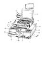
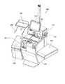
図1は、釣銭機1およびPOS端末2の外観を示す斜視図である。POS端末2は、一般に、一店舗に複数台備え付けられ、ユニークなレジナンバーを割り振られて精算場所に設けられる。キャッシャーは、売上処理にPOS端末2を用いる。POS端末2は、キーボード21、表示器22、スキャナ23(図4参照)などを備えている。 FIG. 1 is a perspective view showing the external appearance of a change machine 1 and a POS terminal 2. In general, a plurality of POS terminals 2 are installed in one store, and a unique cash register number is assigned to the POS terminal 2 at a checkout location. The cashier uses the POS terminal 2 for sales processing. The POS terminal 2 includes a
釣銭機1は、紙幣釣銭機11および硬貨釣銭機12を有する。紙幣釣銭機11は、紙幣を識別して収納し、釣銭としての紙幣を出金する。硬貨釣銭機12は、硬貨を識別して収納し、釣銭としての硬貨を出金する。 The change machine 1 includes a
紙幣釣銭機11は、筐体31を有し、筐体31の上面の手前側端部に、入金口32aと出金口33aと備えている。また、筐体31の上面において出金口33aの奥側には、操作キー38および表示器39が設けられている。 The
硬貨釣銭機12は、筐体51を有し、筐体51の上面の右手前端部に、複数枚の硬貨を一括投入できる入金口46aを備えている。また、筐体51の左手前端部は、硬貨を装置内から出金する出金口47aを備えている。また、筐体51の上面には、操作キー48および表示器49が設けられている。 The
次に、紙幣釣銭機11の構成についてより詳細に説明する。 Next, the configuration of the
サービスの質向上を図る店舗においては、汚れや皺の少ない紙幣を整えて客に手渡したいというニーズがある。そこで以下では、紙幣釣銭機11が汚れや皺の多い紙幣を識別し、回収する例を取り上げて説明する。 There is a need in stores that improve the quality of services to prepare bills with less dirt and wrinkles and hand them to customers. Therefore, in the following, an example in which the banknote change
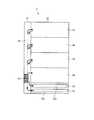
図2は、紙幣釣銭機11の筐体31の内部構成を概略的に説明する平面図である。紙幣釣銭機11は、筐体31に取込部32と出金部33とを備えている。また、紙幣釣銭機11は、筐体31の内部に識別部34、収納部35、および搬送部36を備えている。 FIG. 2 is a plan view schematically illustrating the internal configuration of the
取込部32は、筐体31に形成された入金口32aを有し、入金口32aに差し込まれた紙幣などの紙片を筐体31内へ取り込む。出金部33は、筐体31に形成された出金口33aを有し、出金口33aから釣銭としての紙幣などの紙片を吐き出す。 The take-
取込部32側に近い位置には、搬送ベルト上の紙幣の真偽および金種を判定し、汚れを検出するための識別部34が設けられている。識別部34は、搬送部36を搬送されている紙片が紙幣であるかを識別し、紙幣であればその金種を識別し、枚数を計上する。また、識別部34は、搬送部36を搬送されている紙幣の汚れや皺を検出する。以下では、紙幣の汚れや皺をまとめて「紙幣の汚れ」として記載する。 At a position close to the take-in
汚れの検出方法は特に限定しないが、一例として識別部34が備える識別センサ60(図3参照)の閾値判定等により紙幣の汚れを検出することができる。例えば識別部34が、紙幣に光を照射し、紙幣からの反射光を受光するセンサ(受光素子)を識別センサ60として用いる場合の汚れ検出方法について説明する。一般に、汚れや皺の少ないきれいな紙幣の表面は光を反射しやすく、汚れや皺の多い紙幣の表面は光を反射しにくい。従って、識別部34は、紙幣からの反射光の受光量が所定の閾値を下回った場合に、当該紙幣は汚れていると判定する。尚、識別部34は、受光量の平均値、あるいは受光量に何等かの数値操作を行った値に対して、閾値判定を行ってもよい。 The method for detecting the dirt is not particularly limited, but as an example, the dirt of the banknote can be detected by threshold determination or the like of the identification sensor 60 (see FIG. 3) included in the
尚、上記閾値は、ROM52等の記憶装置が記憶すればよい。また、上記閾値を書き換え可能な記憶装置に記憶しておき、操作キー38(設定手段)からの操作により、汚れ有りと判定する識別センサ60の検出レベルをユーザが変更(設定)できるように構成してもよい。そして、識別部34は、設定された検出レベルに応じて紙幣の汚れを検出すればよい。 The threshold value may be stored in a storage device such as the
収納部35は、第1収納庫41、第2収納庫42、第3収納庫43および回収カセット44を備えている。第1収納庫41は、識別部34が第1金種の紙幣(例えば千円札)だと識別した紙片を収納する。第2収納庫42は、識別部34が第2金種の紙幣(例えば五千円札)だと識別した紙片を収納する。第3収納庫43は、識別部34が第3金種の紙幣(例えば一万円札)だと識別した紙片を収納する。尚、ここでは、収納部35が3種類の金種をそれぞれ収納するための収納庫を3つ備える例について示したが、取り扱う金種数および収納庫は3つに限定されず、2つ以下あるいは4つ以上であってもよい。 The
回収カセット44は、筐体31に対して取り外し可能に設けられており、図示しないロック機構を解除した上で、筐体31から取り外せるように構成されている。回収カセット44は、操作キー38からの指示に基づいて、第1収納庫41、第2収納庫42または第3収納庫43から移動した紙幣を収納する。また、回収カセット44は、識別部34が汚れを検出した紙幣を回収して、一時的に収納しておくための収納庫である。店長などの権限を有するユーザは、回収カセット44を筐体31から取り外し、紙幣を回収カセット44内に収納したまま、POS端末2が設置されているレジカウンタから店舗のバックヤード等の安全性の確保された場所まで持ち運ぶことができる。 The
搬送部36は、入金口32aから収納部35の各収納庫(第1収納庫41、第2収納庫42、第3収納庫43、回収カセット44)まで紙幣を搬送する入金搬送手段として機能する。また、搬送部36は、収納部35の払い出し用の各収納庫(第1収納庫41、第2収納庫42、第3収納庫43)から出金口33aまで紙幣を搬送する出金搬送手段として機能する。 The
搬送部36は、例えば無端状の搬送ベルトを有し、当該搬送ベルトが正方向または逆方向に回転することにより、搬送ベルト上の紙幣を正方向または逆方向に搬送する。尚、正方向とは筐体31の手前側から奥側に向かう方向で、取込部32側から第1収納庫41側に向かう方向である。逆方向とは筐体31の奥側から手前側に向かう方向で、第1収納庫41側から出金部33側に向かう方向である。 The
入金時において搬送部36は、搬送ベルトを正方向に駆動して、取込部32が筐体31内に取り込んだ紙幣を、収納部35の各収納庫(第1収納庫41、第2収納庫42、第3収納庫43、回収カセット44)まで搬入する。 At the time of depositing, the
出金時において搬送部36は、搬送ベルトを逆方向に駆動して、払い出し用の各収納庫が払い出した紙幣を、出金口33aまで搬出する。払い出し用の各収納庫とは、回収カセット44以外の各収納庫、即ち、第1収納庫41、第2収納庫42、第3収納庫43のことである。 At the time of withdrawal, the
尚、ここでは入金時と出金時とで搬送ベルトの回転方向を切り替えて、1つの搬送ベルトを入金搬送用と出金搬送用とに兼用させたが、実施形態はこれに限定されない。その他の構成として、入金搬送用のベルトと出金搬送用のベルトとを別に設けるとしてもよい。 Here, the rotation direction of the conveyor belt is switched between depositing and dispensing, and one conveyor belt is used for both depositing and dispensing, but the embodiment is not limited to this. As another configuration, a depositing / conveying belt and a dispensing / conveying belt may be provided separately.
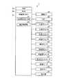
図3は、紙幣釣銭機11の各部の電気的接続を示したブロック図である。紙幣釣銭機11は、筐体31の内部に、CPU(Central Processing Unit)等のプロセッサで構成される制御部51を有している。制御部51は、バスラインにより、ROM(Read Only Memory)52と、RAM(Random Access Memory)53とに接続されている。 FIG. 3 is a block diagram showing the electrical connection of each part of the
また、制御部51は、バスラインおよび各種インタフェースにより、通信I/F(Interface)54、ブザー55、入金口センサ56、入金口モータ57、出金口モータ58、出金口センサ59、識別センサ60、収納庫センサ61、収納庫シャッタ62、回収カセットセンサ63、搬送モータ64にそれぞれ接続されている。また、制御部51は、バスラインおよび各種インタフェースにより、操作キー38と、表示器39(ともに図1参照)とに接続されている。 Further, the
制御部51は、エラーが発生した際にブザー55にエラー音を出力させてエラー報知する。入金口センサ56は入金口32a(図2参照)に設けられ、入金口32aに紙幣が差し込まれたことを検出する。入金口モータ57は、入金口センサ56が紙幣を検出すると、入金口32aに設けられたローラを駆動して入金口32aに差し込まれた紙幣を搬送部36に送り出す。 The
出金口モータ58は、出金口33a(図2参照)に設けられたローラを駆動して搬送部36から出金部33まで搬送された紙幣を、出金口33aの外側へ送り出す。出金口センサ59は出金口33aに設けられ、出金口33aに送り出された紙幣が出金口33aから抜き取られたか否かを検出する。 The dispensing port motor 58 drives a roller provided at the dispensing
識別センサ60は識別部34(図2参照)に設けられている。識別センサ60としては、例えば上述したような紙幣からの反射光を受光する受光センサを用いることができる。 The identification sensor 60 is provided in the identification unit 34 (see FIG. 2). As the identification sensor 60, for example, a light receiving sensor that receives reflected light from a bill as described above can be used.
収納庫センサ61は、収納部35(図2参照)の各収納庫、即ち、第1収納庫41、第2収納庫42、第3収納庫43、回収カセット44の入出金口にそれぞれ設けられている。収納庫センサ61は、入金時に、搬送部36から各収納庫(第1収納庫41、第2収納庫42、第3収納庫43、回収カセット44)に送り込まれる紙幣枚数を計上する。また、収納庫センサ61は、出金時に、回収カセット44以外の各収納庫(第1収納庫41、第2収納庫42、第3収納庫43)から搬送部36へ送り出される紙幣枚数を計上する。 The storage sensor 61 is provided in each storage of the storage unit 35 (see FIG. 2), that is, the deposit / withdrawal port of the
収納庫シャッタ62は、収納部35(図2参照)の各収納庫の入出金口に、それぞれ1つずつ設けられている。各収納庫の収納庫シャッタ62は、各収納庫から紙幣を搬送部36に搬出する際、および、搬送部36から各収納庫内に紙幣を搬入する際に開いて、紙幣の搬入出を可能とする。 One storage shutter 62 is provided at each deposit / withdrawal port of each storage of the storage unit 35 (see FIG. 2). The storage shutter 62 of each storage is opened when a banknote is carried out from each storage to the
回収カセットセンサ63は、収納部35(図2参照)において、回収カセット44を収納する収納枠部の内壁面などに設けられている。回収カセットセンサ63は、回収カセット44が収納部35内に納められたこと、あるいは、取り外されたことを検出する。 The collection cassette sensor 63 is provided on the inner wall surface of the storage frame portion for storing the
搬送モータ64は、搬送部36(図2参照)に設けられ、搬送部36が備える搬送ベルトを正方向または逆方向のいずれかに回動させる。 The
操作キー38(図1参照)は、出金指示、エラー解除、各種設定のための操作などを受付ける。表示器39(図1参照)は、収納部35に収納されている合計在高額、金種ごとの収納枚数(在高枚数)、エラーメッセージ、入金額、出金額などの各種情報を表示する。 The operation key 38 (see FIG. 1) accepts withdrawal instructions, error cancellation, operations for various settings, and the like. The display 39 (see FIG. 1) displays various information such as the total amount of money stored in the
ROM52は、制御部51が実行する各種プログラムや各種データを記憶している。RAM53は、制御部51が各種プログラムを実行する際に一時的にデータやプログラムを記憶する。制御部51は、ROM52に記憶されたプログラムをRAM53に読み出して実行することにより、紙幣釣銭機11の各部を統括的に制御する。 The
なお、紙幣釣銭機11で実行されるプログラムは、ROM52等に予め組み込まれて提供される。紙幣釣銭機11で実行されるプログラムは、インストール可能な形式又は実行可能な形式のファイルでCD−ROM、フレキシブルディスク(FD)、CD−R、DVD(Digital Versatile Disk)等のコンピュータで読み取り可能な記録媒体に記録して提供するように構成してもよい。 The program executed by the
さらに、紙幣釣銭機11で実行されるプログラムを、インターネット等のネットワークに接続されたコンピュータ上に格納し、ネットワーク経由でダウンロードさせることにより提供するように構成しても良い。また、紙幣釣銭機11で実行されるプログラムをインターネット等のネットワーク経由で提供または配布するように構成しても良い。 Furthermore, you may comprise so that the program performed with the
紙幣釣銭機11で実行されるプログラムは、上述した各部(出金指示出力部81、搬送制御部82となっており、実際のハードウェアとしてはCPU(プロセッサ)がROM52からプログラムを読み出して実行することにより上記各部が主記憶装置上にロードされ、主記憶装置上に生成されるようになっている。 The program executed by the
出金指示出力部81は、POS端末2の制御部71から通知された出金指示を受付ける。尚、POS端末2は例えば、釣り金額のうち紙幣で払い出す金額を出金指示として紙幣釣銭機11に通知する。また、出金指示出力部81は、操作キー38から出金額が入力された際にも、当該出金指示を受付ける。出金指示出力部81は、出金合計額から金種ごとの出金枚数を決定し、各金種の収納庫(第1収納庫41、第2収納庫42、第3収納庫43)に出力する。 The withdrawal instruction output unit 81 receives the withdrawal instruction notified from the
搬送制御部82は、搬送部36が有する各機構の動作を統括的に制御する。例えば搬送制御部82は、搬送モータ64の駆動を制御し、搬送部36の搬送ベルトを正方向または逆方向に回転させる。これにより搬送制御部82は、入金時と出金時とで紙幣の搬送方向を切り替える。 The
搬送制御部82は搬送部36を制御して、識別部34が偽札と見なした紙幣を、リジェクト紙幣として出金口33aから排出する。搬送制御部82は搬送部36を制御して、識別部34が真札と見なした紙幣を、識別部34の識別結果に基づいて収納部35のいずれか1つの収納庫に搬送する。 The
より具体的には、搬送部36は、識別部34により汚れ有りと判定された紙幣を、払い出し用の紙幣として用いられることがないよう、回収カセット44に搬入して回収する。 More specifically, the
また、搬送部36は、識別部34が汚れ無し(汚れが少ない)と判定した紙幣を、金種ごとに、第1収納庫41、第2収納庫42、第3収納庫43のいずれか1つに搬入する。つまり搬送部36は、識別部34が第1金種と識別した紙幣を第1収納庫41に搬入する。また、搬送部36は、識別部34が第2金種と識別した紙幣を第2収納庫42に搬入する。また、搬送部36は、識別部34が第3金種と識別した紙幣を第3収納庫43に搬入する。 Moreover, the
また、搬送制御部82は搬送部36を制御して、操作キー38を介して受付けた回収指示に基づき、指示された金種および枚数の紙幣を第1収納庫41、第2収納庫42、第3収納庫43から回収カセット44内まで移動する。 Further, the
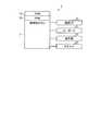
図4は、POS端末2の機能構成を示すブロック図である。POS端末2は、制御部71、ROM72、RAM73を備えている。ROM72は、制御部71が実行する各種プログラムや各種データを記憶する。RAM73は、制御部71が各種プログラムを実行する際に一時的にデータやプログラムを記憶する。制御部71としては、CPU等のプロセッサを用いる。制御部71は、ROM72に記憶されたプログラムをRAM73に読み出して実行することにより、POS端末2の各部を統括的に制御する。 FIG. 4 is a block diagram showing a functional configuration of the POS terminal 2. The POS terminal 2 includes a
また、制御部71には、バスラインを介して通信I/F74が接続されている。通信I/F74は、釣銭機1との間でデータ送受信を行うためのインタフェースである。また、制御部71には、バスラインを介してキーボード21(図1参照)、表示器22(図1参照)、スキャナ23等のI/O機器が接続されている。スキャナ23は、バーコードや二次元コード等の形態で各商品に付加された商品コードを読み取る。 In addition, a communication I /
制御部71は、スキャナ23が商品コードを読み取ると、この商品コードを商品マスタに問い合わせて、商品コードに対応する商品の商品情報(単価など)を読み込む。尚、商品マスタは、POS端末2にLAN(Local Area Network)等の接続回線で接続されたストアサーバが有していてもよい。そして、制御部71は、接続回線を介して、当該商品マスタに商品情報を問い合わせてもよい。あるいは制御部71は、ストアサーバから商品マスタをダウンロードしてPOS端末2内に保存し、保存先の商品マスタに商品情報を問い合わせてもよい。 When the
制御部71は、商品の単価および販売個数に基づき、一取引の合計金額を算出し、決済処理を行う。また、制御部71は、取引内容の商品情報や価格、個数、合計金額、預り金額、釣り金額等の情報を用いて、当該取引の売上データを生成する。そして制御部71は、当該売上データを所定のタイミングでストアサーバに送信し、ストアサーバが管理する売上ファイルに売上データを登録する。 The
次に、POS端末2と釣銭機1とが協働して行う決済処理について説明する。POS端末2の制御部71は一取引の合計金額を表示器22に表示する。客は表示金額を参照して店員に現金を支払う。店員は、客から受け取った代金のうちの紙幣を紙幣釣銭機11の入金口32aに差し込む。また店員は、客から受け取った代金のうちの硬貨を硬貨釣銭機12の入金口46aに投入する。入金口32aに差し込まれた紙幣は、入金口モータ57により筐体31内部の搬送部36に取り込まれ、識別部34によって真偽判定、金種識別、および、汚れ検出がなされる。 Next, settlement processing performed in cooperation between the POS terminal 2 and the change machine 1 will be described. The
搬送制御部82は、識別部34が汚れ有りと判定した紙幣を、搬送部36によって回収カセット44に回収する。搬送制御部82は搬送部36により、識別部34が汚れ無しと判定した紙幣を、識別部34が識別した金種に応じて、第1収納庫41、第2収納庫42、第3収納庫43のいずれか1つに収納する。 The
紙幣釣銭機11および硬貨釣銭機12はそれぞれ、紙幣の入金額及び硬貨の入金額を算出し、POS端末2に通知する。即ち、紙幣釣銭機11は、識別部34が識別した金種および紙幣枚数に基づいて、入金額を算出する。尚、この際、紙幣釣銭機11は汚れを検出し回収カセット44に回収した紙幣分についても、入金扱いとしてその金種、枚数を入金額に含めて計上する。 The
POS端末2の制御部71は、通知された紙幣及び硬貨の入金額の合計から、商品価格の合計金額を減算して釣り金額を算出する。そしてPOS端末2の制御部71は、釣り金額のうち紙幣にて客に返却する額を出金指示に含めて、紙幣釣銭機11に通知する。また、制御部71は、硬貨にて客に返却する額を出金指示に含めて硬貨釣銭機12に通知する。また、制御部71は、プリンタによりレシートを印字する。 The
硬貨釣銭機12は、POS端末2からの出金指示に基づいて、通知された出金額の硬貨を出金する。紙幣釣銭機11は、POS端末2からの出金指示に基づいて、通知された出金額の紙幣を出金する。店員は、お釣りとして出金された紙幣、硬貨およびレシートを客に渡す。このようにして一取引の決済が完了する。 Based on the withdrawal instruction from the POS terminal 2, the
以上説明したように、紙幣釣銭機11は、汚れを検出しなかった紙幣は払い出し用の紙幣を収納する収納部35に搬入するが、汚れを検出した紙幣は回収カセット44に回収する。これにより、汚れた紙幣は入金扱いされるが、釣りとして払い出されることはない。従って、汚れた紙幣を店員が取り除き、きれいな紙幣に替えてから客に手渡すという手間を省くことができ、手間をかけずにサービスの質の向上を図ることが可能となる。 As described above, the
また、紙幣釣銭機11は、汚れ有りとみなした紙幣をリジェクト(差し戻し)せず、その金額を入金扱いとして入金額を計上する。つまり、店舗側は、汚れた紙幣を引き取るが客には渡さないことで、客側に不便をかけずに、サービスの向上を図ることができる。 Moreover, the
また、上述した紙幣釣銭機11は、入金後直ちに汚れた紙幣を識別して回収するので、出金処理は従来と同様、金種の収納庫から出金口33aに直接紙幣を搬送すればよい。従って、客にお釣りを渡すまでに要する時間を、従来と同程度にとすることができる。 Moreover, since the
なお、上述では、入金時に汚れた紙幣を検出して回収する構成例について説明したが、回収のタイミングはこれに限定しない。その他の例として、出金時に汚れた紙幣を検出して回収してもよい。 In addition, although the above demonstrated the structural example which detects and collect | recovers the banknote which became dirty at the time of money_receiving | payment, the collection timing is not limited to this. As another example, banknotes that are soiled at the time of withdrawal may be detected and collected.
・出金時に回収する場合の構成例
出金時に汚れた紙幣を回収する場合の構成例について説明する。第1収納庫41、第2収納庫42、第3収納庫43は、出金指示出力部81の出金指示に基づいて各金種の紙幣を搬送部36へと送り出す。搬送制御部82は、搬送モータ64を逆回転させて搬送ベルトを逆方向に搬送し、各収納庫から送り出された紙幣を識別部34が設けられた位置まで搬送する。識別部34が汚れを検出しなかった紙幣については、搬送部36がそのまま出金口33aまで搬送し、出金口モータ58と協働して、紙幣を出金口33aに送り出す。-Configuration example in the case of collecting at the time of withdrawal A configuration example in the case of collecting a dirty bill at the time of withdrawal will be described. The
一方、搬送制御部82は搬送部36を制御して、識別部34が汚れを検出した紙幣を出金口33aには払い出さずに、回収カセット44内へと送り込む。そして、識別部34は汚れを検出した金種を出金指示出力部81に通知する。また、回収カセット44に設けられた収納庫センサ61は、回収した紙幣枚数を出金指示出力部81に通知する。出金指示出力部81は、通知された金種とその枚数を含む出金指示を新たに出力する。そして金種ごとの収納庫(第1収納庫41、第2収納庫42、第3収納庫43)および搬送部36は、回収分の紙幣を再度払い出す。これにより紙幣釣銭機11は、回収分の金額を補って当初の釣り金額が全額払い出されるよう制御する。 On the other hand, the
このように出金時に汚れた紙幣を回収した場合にも、上述と同様、客に手渡すお釣りに汚れた紙幣を含めないようにすることができる。 As described above, even when the banknotes collected at the time of withdrawal are collected, the banknotes handed over to the customer can be prevented from being included.
・回収部のその他の構成例
また、上述では、収納部35に回収カセット44を1つ設けて、金種に寄らず汚れた紙幣はこの回収カセット44に回収するとしたが、金種ごとに回収部を設けて分別回収してもよい。また、図2では、回収カセット44を収納部35の手前側に設けた例を示したが、回収カセット44を収納部35の奥側、例えば第1収納庫41の奥側に設けてもよい。-Other configuration examples of the collection unit In addition, in the above description, one
・硬貨釣銭機12への適用例
また、上述では、紙幣釣銭機11において汚れた紙幣を検出し、回収する例について説明したが、硬貨釣銭機12において汚れた硬貨を検出し、回収してもよい。汚れの検出方法は、上述と同様に受光センサを用いて検出してもよいし、材質センサ等のその他のセンサを用いて検出してもよい。-Application example to coin
汚れた硬貨を回収するための回収部としては、硬貨搬送経路の下方に設けた引出ボックス等を利用すればよい(例えば、特許第5620442号公報に記載の構成を参照のこと)。例として、識別部が汚れた硬貨を検出すると、搬送経路に設けられたシャッタが開いて搬送中の硬貨が搬送経路下方の引出ボックスに落ちる。これにより紙幣同様、硬貨についても汚れ有りと判定したものの入金は許可するが、収納部には収納せずに回収部に分別しておくことができる。つまり、汚れの多い硬貨を釣銭として出金しないようにできる。 What is necessary is just to utilize the drawer | drawing-out box etc. which were provided below the coin conveyance path | route as a collection | recovery part for collect | recovering dirty coins (for example, refer the structure as described in patent 5620442). As an example, when the identifying unit detects a dirty coin, a shutter provided in the transport path opens, and the coin being transported falls into a drawer box below the transport path. Thus, as with banknotes, coins that have been determined to be dirty are allowed to be deposited, but can be sorted into the collection unit without being stored in the storage unit. That is, it is possible not to withdraw coins with a lot of dirt as change.
・その他の装置構成例
また、上述では、POS端末2と接続されて用いる釣銭機1(紙幣釣銭機11または硬貨釣銭機12)に本実施形態の金銭処理装置を適用した例について説明したが、実施形態はこれに限定されるものではない。例えば、本実施形態の金銭処理装置として、ATM(Automated Teller Machine)に内蔵される入出金装置を用いてもよい。また、入金、出金のいずれか一方を行う金銭処理装置に上記構成を適用してもよい。-Other apparatus structural example Moreover, although the above-mentioned demonstrated the example which applied the money processing apparatus of this embodiment to the change machine 1 (The
また、その他の態様として、釣銭機1およびPOS端末2の機能構成を備えた1台構成の装置に、上述した本実施形態を適用してもよい。装置の例としては、スーパーマーケットやコンビニエンスストア等の店舗で用いられるセルフチェックアウト装置(以降、単にセルフPOSと称する)を利用することができる。 In addition, as another aspect, the above-described embodiment may be applied to a single-unit apparatus having the functional configurations of the change machine 1 and the POS terminal 2. As an example of the device, a self-checkout device (hereinafter simply referred to as self-POS) used in a store such as a supermarket or a convenience store can be used.
図5は、その他の態様であるセルフPOS200の概略的構成を示した外観斜視図である。図5に示すように、セルフPOS200の本体202は、タッチパネル105が表面に配設された表示デバイス106や、商品の種別等を認識(検出)するために商品画像を読み取る商品読取部110を備えている。 FIG. 5 is an external perspective view showing a schematic configuration of a self-
表示デバイス106としては例えば液晶表示器が用いられる。表示デバイス106は、客にセルフPOS200の操作方法を知らせるための案内画面や、各種の入力画面や、商品読取部110で読み込んだ商品情報を表示する登録画面、商品の合計金額や預かり金額、釣銭額等を表示し、支払い方法の選択をする精算画面等を表示する。 For example, a liquid crystal display is used as the
商品読取部110は、客が商品に付されたコードシンボルを商品読取部110の読取窓103にかざすことで商品画像を読取窓103の内部に設けられた撮像部により読み取る。 The
また、本体202の右側にはかごに入った未清算の商品を置くための商品載置台203が設けられている。本体202の左側には精算済みの商品を置くための商品載置台204が設けられている。商品載置台204の奥側の上面には、精算済みの商品を袋に入れる前に一時的に置いておくための一時置き台206が突出して設けられている。一時置き台206の手前側端部には、精算済みの商品を入れるための袋を掛けるための袋掛けフック205が一対、設けられている。商品載置台203および204はそれぞれ計量器を備えており、精算の前後で商品の重量が同じであることを確認する機能を有している。 Further, on the right side of the
また、セルフPOS200の本体202には、精算用の紙幣の入金や釣り紙幣の受け取りを行うための釣銭機201が設けられている。 Further, the
このような構成のセルフPOS200において、上述した釣銭機1(図1ないし図3参照)の機能構成を、釣銭機201に適用すればよい。また、上述したPOS端末2(図1、図5参照)の機能構成を、セルフPOS200に適用すればよい。 In the self-
本発明のいくつかの実施形態を説明したが、これらの実施形態は、例として提示したものであり、発明の範囲を限定することは意図していない。これら新規な実施形態は、その他の様々な形態で実施されることが可能であり、発明の要旨を逸脱しない範囲で、種々の省略、置き換え、変更を行うことができる。これら実施形態やその変形は、発明の範囲や要旨に含まれるとともに、特許請求の範囲に記載された発明とその均等の範囲に含まれる。 Although several embodiments of the present invention have been described, these embodiments are presented by way of example and are not intended to limit the scope of the invention. These novel embodiments can be implemented in various other forms, and various omissions, replacements, and changes can be made without departing from the scope of the invention. These embodiments and modifications thereof are included in the scope and gist of the invention, and are included in the invention described in the claims and the equivalents thereof.
以上説明したとおり、本実施形態の金銭処理装置(一例として、釣銭機1)は、汚れを検出した貨幣を出金口に払い出さずに回収部に回収する。従って本実施形態によれば、汚れた貨幣を出金しない金銭処理装置を提供することができる。 As described above, the money processing apparatus (as an example, the change machine 1) according to the present embodiment collects the money in which the dirt has been detected in the collecting unit without paying out the money to the dispensing port. Therefore, according to this embodiment, it is possible to provide a money processing apparatus that does not dispense dirty money.
1…釣銭機、2…POS端末、11…紙幣釣銭機、12…硬貨釣銭機、35…収納部、44…回収カセット、32…取込部、33…出金部、32a…入金口、33a…出金口、34…識別部、36…搬送部、81…出金指示出力部、82…搬送制御部。 DESCRIPTION OF SYMBOLS 1 ... Change machine, 2 ... POS terminal, 11 ... Banknote change machine, 12 ... Coin change machine, 35 ... Storage part, 44 ... Collection cassette, 32 ... Intake part, 33 ... Withdrawal part, 32a ... Deposit port, 33a A withdrawal port, 34 an identification unit, 36 a conveyance unit, 81 a withdrawal instruction output unit, and 82 a conveyance control unit.
Claims (4)
Translated fromJapanese入金口から前記収納部まで貨幣を搬送する入金搬送手段と、
前記入金搬送手段により搬送されている貨幣について、真偽を判定し、真の貨幣であれば、金種の識別と、枚数の計上と、汚れの検出とを行う識別手段と、
前記識別手段が偽と見なした貨幣を出金口から排出する排出手段と、
前記識別手段が汚れを検出した貨幣を回収部に回収する回収手段と、
前記識別手段が汚れを検出しなかった貨幣を金種ごとに分別して前記収納部に搬送する分別手段と、
前記回収部に回収する貨幣の金種および枚数と、前記収納部に搬送する貨幣の金種および枚数とに基づいて、前記入金口から入金された入金額を算出する入金額算出手段と、
前記入金額算出手段が算出した前記入金額を通知する入金額通知手段と、
を備えた金銭処理装置。A storage unit for storing money for payout in denominations;
A deposit transport means for transporting money from the deposit port to the storage unit;
Monetary being transported byentering-gold conveyingmeans, to determine the authenticity, if true of money,the identificationof thedenomination, the recorded number of sheets, and identification meansfor performing a detectionof dirt,
Discharging means for discharging the money regarded as false by the identification means from the withdrawal port;
A collecting means for collecting the money, which is detected by the identifying means, ina collecting unit;
Sorting means for sorting the money that the identification means did not detect dirt by denomination and transporting it to the storage unit;
A deposit amount calculating means for calculating the deposit amount deposited from the deposit slot based on the denomination and number of money to be collected in the collection unit and the denomination and number of money to be conveyed to the storage unit;
A deposit amount notification means for notifying the deposit amount calculated by the deposit amount calculation means;
A money processing apparatus comprising:
操作手段から受付けた回収指示に基づき、指示された金種および枚数の貨幣を前記収納部から前記回収部に移動する移動手段を更に備えた、
請求項1に記載の金銭処理装置。As the collection unit, provided with a collection box detachably attached to the own device,
Based on the collection instruction received from the operation means, further comprises a moving means for moving the designated denomination and the number of coins from the storage section to the collection section.
The money processing apparatus according to claim 1.
前記識別手段は、前記設定手段が設定した前記検出レベルに応じて前記貨幣の汚れを検出する、請求項1または2に記載の金銭処理装置。The identification means further comprises a setting means for setting a detection level for detecting dirt of money;
The money processing apparatus according to claim 1, wherein the identification unit detects the dirt of the money according to the detection level set by the setting unit.
Priority Applications (4)
| Application Number | Priority Date | Filing Date | Title |
|---|---|---|---|
| JP2015022645AJP6250573B2 (en) | 2015-02-06 | 2015-02-06 | Money processing equipment |
| US14/992,161US9792496B2 (en) | 2015-02-06 | 2016-01-11 | Cash processing apparatus |
| EP16154467.1AEP3054428A3 (en) | 2015-02-06 | 2016-02-05 | Cash processing apparatus and system |
| CN201610081262.4ACN105869312A (en) | 2015-02-06 | 2016-02-05 | Cash processing apparatus |
Applications Claiming Priority (1)
| Application Number | Priority Date | Filing Date | Title |
|---|---|---|---|
| JP2015022645AJP6250573B2 (en) | 2015-02-06 | 2015-02-06 | Money processing equipment |
Related Child Applications (1)
| Application Number | Title | Priority Date | Filing Date |
|---|---|---|---|
| JP2017223730ADivisionJP2018028946A (en) | 2017-11-21 | 2017-11-21 | Money processing equipment |
Publications (2)
| Publication Number | Publication Date |
|---|---|
| JP2016146067A JP2016146067A (en) | 2016-08-12 |
| JP6250573B2true JP6250573B2 (en) | 2017-12-20 |
Family
ID=55304928
Family Applications (1)
| Application Number | Title | Priority Date | Filing Date |
|---|---|---|---|
| JP2015022645AExpired - Fee RelatedJP6250573B2 (en) | 2015-02-06 | 2015-02-06 | Money processing equipment |
Country Status (4)
| Country | Link |
|---|---|
| US (1) | US9792496B2 (en) |
| EP (1) | EP3054428A3 (en) |
| JP (1) | JP6250573B2 (en) |
| CN (1) | CN105869312A (en) |
Families Citing this family (2)
| Publication number | Priority date | Publication date | Assignee | Title |
|---|---|---|---|---|
| JP6790642B2 (en)* | 2016-09-16 | 2020-11-25 | 富士電機株式会社 | Banknote processing device |
| JP2020140294A (en) | 2019-02-27 | 2020-09-03 | グローリー株式会社 | Currency processor and currency processing system |
Family Cites Families (15)
| Publication number | Priority date | Publication date | Assignee | Title |
|---|---|---|---|---|
| JP2532671B2 (en)* | 1989-07-24 | 1996-09-11 | 沖電気工業株式会社 | Cash deposit / withdrawal processing device |
| JP3263112B2 (en)* | 1992-02-05 | 2002-03-04 | 株式会社東芝 | Bill discrimination device |
| US6074081A (en)* | 1995-05-11 | 2000-06-13 | Giesecke & Devrient Gmbh | Apparatus and method for processing sheet articles such as bank notes |
| JP3690080B2 (en)* | 1996-09-20 | 2005-08-31 | 株式会社日立製作所 | Automatic cash transaction equipment |
| JP2000099804A (en)* | 1998-09-18 | 2000-04-07 | Toshiba Corp | Banknote handling device with unfit bill reject storage |
| EP1434176A1 (en)* | 2002-12-27 | 2004-06-30 | Mars, Incorporated | Banknote validator |
| JP2006120074A (en) | 2004-10-25 | 2006-05-11 | Toshiba Tec Corp | Product sales data processing device |
| WO2007044570A2 (en)* | 2005-10-05 | 2007-04-19 | Cummins-Allison Corp. | Currency processing system with fitness detection |
| EP2267666B1 (en) | 2008-04-16 | 2014-08-20 | Glory Ltd. | Bill processing device and bill processing method |
| EP2144203B1 (en)* | 2008-07-07 | 2019-04-10 | Kabushiki Kaisha Toshiba | Sheet processing system, sheet processing apparatus, and sheet processing method |
| JP5275874B2 (en)* | 2009-03-27 | 2013-08-28 | 富士通フロンテック株式会社 | Paper sheet processing equipment |
| JP2010277252A (en)* | 2009-05-27 | 2010-12-09 | Toshiba Corp | Paper sheet discrimination device |
| DE102009048002A1 (en)* | 2009-10-02 | 2011-04-07 | Beb Industrie-Elektronik Ag | Method and device for checking the degree of soiling of banknotes |
| WO2012090301A1 (en)* | 2010-12-28 | 2012-07-05 | 富士通フロンテック株式会社 | Deposit and withdrawal device, replenishment and collection device, and operating method of the deposit and withdrawal device |
| JP5620442B2 (en) | 2012-09-05 | 2014-11-05 | 東芝テック株式会社 | Coin deposit / withdrawal device and deformed true coin separation method |
- 2015
- 2015-02-06JPJP2015022645Apatent/JP6250573B2/ennot_activeExpired - Fee Related
- 2016
- 2016-01-11USUS14/992,161patent/US9792496B2/ennot_activeExpired - Fee Related
- 2016-02-05EPEP16154467.1Apatent/EP3054428A3/ennot_activeWithdrawn
- 2016-02-05CNCN201610081262.4Apatent/CN105869312A/enactivePending
Also Published As
| Publication number | Publication date |
|---|---|
| EP3054428A3 (en) | 2016-12-21 |
| CN105869312A (en) | 2016-08-17 |
| EP3054428A2 (en) | 2016-08-10 |
| US20160232406A1 (en) | 2016-08-11 |
| JP2016146067A (en) | 2016-08-12 |
| US9792496B2 (en) | 2017-10-17 |
Similar Documents
| Publication | Publication Date | Title |
|---|---|---|
| CN105513224A (en) | Currency processing device and input money control method for currency processing device | |
| JP6208700B2 (en) | Money processing equipment | |
| JP6250573B2 (en) | Money processing equipment | |
| CN106169202B (en) | Paper money processing device | |
| JP7267075B2 (en) | Deposit/withdrawal device, deposit/withdrawal system, and deposit/withdrawal method | |
| JP6685724B2 (en) | Deposit / withdrawal device, information processing device, and accounting device | |
| JP6770372B2 (en) | Money processing machine, money processing system and money processing method | |
| JP6193288B2 (en) | Deposit / withdrawal equipment | |
| JP2017199431A (en) | Deposit / withdrawal equipment | |
| JP2018028946A (en) | Money processing equipment | |
| JP6599525B2 (en) | Money processing apparatus, program and deposit / withdrawal system | |
| JP5329612B2 (en) | POS system | |
| JP6389311B2 (en) | Deposit / withdrawal system | |
| JP6827313B2 (en) | Money processing machine and money processing system | |
| JP4534730B2 (en) | Cash processing equipment | |
| JP4412014B2 (en) | Money handling equipment | |
| JP6576687B2 (en) | Money handling system and money handling method | |
| JP7495314B2 (en) | Paper money deposit and withdrawal device and program | |
| EP4064233A1 (en) | Money processing device | |
| JP6431221B2 (en) | Sales data processing apparatus and program | |
| JP6522903B2 (en) | Value medium processing device, value medium processing system, and value medium processing method | |
| JP2017049679A (en) | Money processing device and money processing method | |
| JP5681764B2 (en) | POS system | |
| JP6584160B2 (en) | Money handling apparatus and money handling method | |
| JP2022108465A (en) | media handling equipment |
Legal Events
| Date | Code | Title | Description |
|---|---|---|---|
| A621 | Written request for application examination | Free format text:JAPANESE INTERMEDIATE CODE: A621 Effective date:20160915 | |
| A977 | Report on retrieval | Free format text:JAPANESE INTERMEDIATE CODE: A971007 Effective date:20170721 | |
| A131 | Notification of reasons for refusal | Free format text:JAPANESE INTERMEDIATE CODE: A131 Effective date:20170801 | |
| A521 | Request for written amendment filed | Free format text:JAPANESE INTERMEDIATE CODE: A523 Effective date:20171002 | |
| TRDD | Decision of grant or rejection written | ||
| A01 | Written decision to grant a patent or to grant a registration (utility model) | Free format text:JAPANESE INTERMEDIATE CODE: A01 Effective date:20171024 | |
| A61 | First payment of annual fees (during grant procedure) | Free format text:JAPANESE INTERMEDIATE CODE: A61 Effective date:20171122 | |
| R150 | Certificate of patent or registration of utility model | Ref document number:6250573 Country of ref document:JP Free format text:JAPANESE INTERMEDIATE CODE: R150 | |
| LAPS | Cancellation because of no payment of annual fees |