JP6249951B2 - Method for forming a web from a fibrous material - Google Patents
Method for forming a web from a fibrous materialDownload PDFInfo
- Publication number
- JP6249951B2 JP6249951B2JP2014533481AJP2014533481AJP6249951B2JP 6249951 B2JP6249951 B2JP 6249951B2JP 2014533481 AJP2014533481 AJP 2014533481AJP 2014533481 AJP2014533481 AJP 2014533481AJP 6249951 B2JP6249951 B2JP 6249951B2
- Authority
- JP
- Japan
- Prior art keywords
- web
- layered
- glass fibers
- per square
- exemplary embodiment
- Prior art date
- Legal status (The legal status is an assumption and is not a legal conclusion. Google has not performed a legal analysis and makes no representation as to the accuracy of the status listed.)
- Active
Links
- 238000000034methodMethods0.000titledescription73
- 239000002657fibrous materialSubstances0.000titledescription43
- 239000003365glass fiberSubstances0.000claimsdescription125
- 238000004806packaging method and processMethods0.000claimsdescription10
- 230000007246mechanismEffects0.000description145
- 239000000835fiberSubstances0.000description95
- 239000002706dry binderSubstances0.000description71
- 239000011230binding agentSubstances0.000description64
- 239000000463materialSubstances0.000description59
- 239000010410layerSubstances0.000description45
- 239000007789gasSubstances0.000description32
- 239000000314lubricantSubstances0.000description22
- 230000008569processEffects0.000description17
- 238000005520cutting processMethods0.000description16
- 238000010924continuous productionMethods0.000description15
- XLYOFNOQVPJJNP-UHFFFAOYSA-NwaterSubstancesOXLYOFNOQVPJJNP-UHFFFAOYSA-N0.000description15
- 239000006060molten glassSubstances0.000description14
- 239000003921oilSubstances0.000description10
- 235000019198oilsNutrition0.000description10
- 239000000428dustSubstances0.000description9
- 238000004519manufacturing processMethods0.000description9
- 239000000839emulsionSubstances0.000description8
- 239000000126substanceSubstances0.000description8
- 229920001187thermosetting polymerPolymers0.000description8
- 230000015572biosynthetic processEffects0.000description7
- -1but not limited toSubstances0.000description7
- 238000010586diagramMethods0.000description7
- 239000011521glassSubstances0.000description7
- 238000009413insulationMethods0.000description7
- 239000007788liquidSubstances0.000description7
- 239000000843powderSubstances0.000description7
- 241000288673ChiropteraSpecies0.000description6
- 239000007921spraySubstances0.000description6
- 238000011437continuous methodMethods0.000description5
- 238000009826distributionMethods0.000description5
- 238000002844meltingMethods0.000description5
- 230000008018meltingEffects0.000description5
- 238000004513sizingMethods0.000description5
- 229920001169thermoplasticPolymers0.000description5
- 239000004416thermosoftening plasticSubstances0.000description5
- 239000002699waste materialSubstances0.000description5
- 239000000654additiveSubstances0.000description4
- 230000000996additive effectEffects0.000description4
- 239000000853adhesiveSubstances0.000description4
- 230000001070adhesive effectEffects0.000description4
- 238000007664blowingMethods0.000description4
- 150000001875compoundsChemical class0.000description4
- 239000003085diluting agentSubstances0.000description4
- 238000007688edgingMethods0.000description4
- 239000012943hotmeltSubstances0.000description4
- 239000002557mineral fiberSubstances0.000description4
- 239000002480mineral oilSubstances0.000description4
- 235000010446mineral oilNutrition0.000description4
- 239000002245particleSubstances0.000description4
- 229920001296polysiloxanePolymers0.000description4
- 239000007787solidSubstances0.000description4
- 229920006132styrene block copolymerPolymers0.000description4
- 238000012546transferMethods0.000description4
- 235000015112vegetable and seed oilNutrition0.000description4
- 239000008158vegetable oilSubstances0.000description4
- 230000006835compressionEffects0.000description3
- 238000007906compressionMethods0.000description3
- 238000009434installationMethods0.000description3
- 230000033001locomotionEffects0.000description3
- 239000000155meltSubstances0.000description3
- 239000000203mixtureSubstances0.000description3
- 230000035515penetrationEffects0.000description3
- 238000003860storageMethods0.000description3
- 238000013517stratificationMethods0.000description3
- 230000007723transport mechanismEffects0.000description3
- 239000004952PolyamideSubstances0.000description2
- 239000004743PolypropyleneSubstances0.000description2
- BLRPTPMANUNPDV-UHFFFAOYSA-NSilaneChemical compound[SiH4]BLRPTPMANUNPDV-UHFFFAOYSA-N0.000description2
- UIIMBOGNXHQVGW-UHFFFAOYSA-MSodium bicarbonateChemical compound[Na+].OC([O-])=OUIIMBOGNXHQVGW-UHFFFAOYSA-M0.000description2
- 239000004433Thermoplastic polyurethaneSubstances0.000description2
- 238000006243chemical reactionMethods0.000description2
- 239000003086colorantSubstances0.000description2
- 238000001816coolingMethods0.000description2
- 230000008021depositionEffects0.000description2
- 238000005137deposition processMethods0.000description2
- 238000013461designMethods0.000description2
- 238000011143downstream manufacturingMethods0.000description2
- 230000007613environmental effectEffects0.000description2
- 229920006228ethylene acrylate copolymerPolymers0.000description2
- 239000005038ethylene vinyl acetateSubstances0.000description2
- 239000012530fluidSubstances0.000description2
- 238000010438heat treatmentMethods0.000description2
- 229920001903high density polyethylenePolymers0.000description2
- 239000004700high-density polyethyleneSubstances0.000description2
- 229920001684low density polyethylenePolymers0.000description2
- 239000004702low-density polyethyleneSubstances0.000description2
- 238000012423maintenanceMethods0.000description2
- 238000002156mixingMethods0.000description2
- 239000006199nebulizerSubstances0.000description2
- 239000012071phaseSubstances0.000description2
- 229920001200poly(ethylene-vinyl acetate)Polymers0.000description2
- 229920002647polyamidePolymers0.000description2
- 229920000728polyesterPolymers0.000description2
- 229920000642polymerPolymers0.000description2
- 229920001155polypropylenePolymers0.000description2
- 239000002994raw materialSubstances0.000description2
- 238000011084recoveryMethods0.000description2
- 229920005989resinPolymers0.000description2
- 239000011347resinSubstances0.000description2
- 229910000077silaneInorganic materials0.000description2
- 239000002356single layerSubstances0.000description2
- 239000000758substrateSubstances0.000description2
- 238000010998test methodMethods0.000description2
- 229920002803thermoplastic polyurethanePolymers0.000description2
- 229920005992thermoplastic resinPolymers0.000description2
- 238000009966trimmingMethods0.000description2
- 238000011144upstream manufacturingMethods0.000description2
- 238000003466weldingMethods0.000description2
- RNFJDJUURJAICM-UHFFFAOYSA-N2,2,4,4,6,6-hexaphenoxy-1,3,5-triaza-2$l^{5},4$l^{5},6$l^{5}-triphosphacyclohexa-1,3,5-trieneChemical compoundN=1P(OC=2C=CC=CC=2)(OC=2C=CC=CC=2)=NP(OC=2C=CC=CC=2)(OC=2C=CC=CC=2)=NP=1(OC=1C=CC=CC=1)OC1=CC=CC=C1RNFJDJUURJAICM-UHFFFAOYSA-N0.000description1
- 238000012935AveragingMethods0.000description1
- 206010016654FibrosisDiseases0.000description1
- 238000004026adhesive bondingMethods0.000description1
- 239000003831antifriction materialSubstances0.000description1
- 239000012736aqueous mediumSubstances0.000description1
- 230000004888barrier functionEffects0.000description1
- 230000009286beneficial effectEffects0.000description1
- 230000005540biological transmissionEffects0.000description1
- 230000000903blocking effectEffects0.000description1
- 239000000919ceramicSubstances0.000description1
- 238000004140cleaningMethods0.000description1
- 230000003750conditioning effectEffects0.000description1
- 238000004132cross linkingMethods0.000description1
- 238000001035dryingMethods0.000description1
- 230000008030eliminationEffects0.000description1
- 238000003379elimination reactionMethods0.000description1
- 238000000605extractionMethods0.000description1
- 239000011152fibreglassSubstances0.000description1
- 230000004761fibrosisEffects0.000description1
- 239000003063flame retardantSubstances0.000description1
- 230000004886head movementEffects0.000description1
- 229910052500inorganic mineralInorganic materials0.000description1
- 239000012774insulation materialSubstances0.000description1
- 238000010030laminatingMethods0.000description1
- 238000005259measurementMethods0.000description1
- 239000011707mineralSubstances0.000description1
- 235000010755mineralNutrition0.000description1
- 238000012986modificationMethods0.000description1
- 230000004048modificationEffects0.000description1
- 239000012768molten materialSubstances0.000description1
- 238000012545processingMethods0.000description1
- 230000009467reductionEffects0.000description1
- 230000008439repair processEffects0.000description1
- 239000011435rockSubstances0.000description1
- 239000002893slagSubstances0.000description1
- 229910000030sodium bicarbonateInorganic materials0.000description1
- 235000017557sodium bicarbonateNutrition0.000description1
- 239000007790solid phaseSubstances0.000description1
- 238000005507sprayingMethods0.000description1
- 239000004753textileSubstances0.000description1
Images


Classifications
- D—TEXTILES; PAPER
- D04—BRAIDING; LACE-MAKING; KNITTING; TRIMMINGS; NON-WOVEN FABRICS
- D04H—MAKING TEXTILE FABRICS, e.g. FROM FIBRES OR FILAMENTARY MATERIAL; FABRICS MADE BY SUCH PROCESSES OR APPARATUS, e.g. FELTS, NON-WOVEN FABRICS; COTTON-WOOL; WADDING ; NON-WOVEN FABRICS FROM STAPLE FIBRES, FILAMENTS OR YARNS, BONDED WITH AT LEAST ONE WEB-LIKE MATERIAL DURING THEIR CONSOLIDATION
- D04H3/00—Non-woven fabrics formed wholly or mainly of yarns or like filamentary material of substantial length
- D04H3/002—Inorganic yarns or filaments
- D04H3/004—Glass yarns or filaments
- C—CHEMISTRY; METALLURGY
- C03—GLASS; MINERAL OR SLAG WOOL
- C03B—MANUFACTURE, SHAPING, OR SUPPLEMENTARY PROCESSES
- C03B37/00—Manufacture or treatment of flakes, fibres, or filaments from softened glass, minerals, or slags
- C03B37/01—Manufacture of glass fibres or filaments
- C03B37/04—Manufacture of glass fibres or filaments by using centrifugal force, e.g. spinning through radial orifices; Construction of the spinner cups therefor
- C—CHEMISTRY; METALLURGY
- C03—GLASS; MINERAL OR SLAG WOOL
- C03C—CHEMICAL COMPOSITION OF GLASSES, GLAZES OR VITREOUS ENAMELS; SURFACE TREATMENT OF GLASS; SURFACE TREATMENT OF FIBRES OR FILAMENTS MADE FROM GLASS, MINERALS OR SLAGS; JOINING GLASS TO GLASS OR OTHER MATERIALS
- C03C25/00—Surface treatment of fibres or filaments made from glass, minerals or slags
- C03C25/10—Coating
- C03C25/1095—Coating to obtain coated fabrics
- D—TEXTILES; PAPER
- D04—BRAIDING; LACE-MAKING; KNITTING; TRIMMINGS; NON-WOVEN FABRICS
- D04H—MAKING TEXTILE FABRICS, e.g. FROM FIBRES OR FILAMENTARY MATERIAL; FABRICS MADE BY SUCH PROCESSES OR APPARATUS, e.g. FELTS, NON-WOVEN FABRICS; COTTON-WOOL; WADDING ; NON-WOVEN FABRICS FROM STAPLE FIBRES, FILAMENTS OR YARNS, BONDED WITH AT LEAST ONE WEB-LIKE MATERIAL DURING THEIR CONSOLIDATION
- D04H1/00—Non-woven fabrics formed wholly or mainly of staple fibres or like relatively short fibres
- D04H1/40—Non-woven fabrics formed wholly or mainly of staple fibres or like relatively short fibres from fleeces or layers composed of fibres without existing or potential cohesive properties
- D04H1/42—Non-woven fabrics formed wholly or mainly of staple fibres or like relatively short fibres from fleeces or layers composed of fibres without existing or potential cohesive properties characterised by the use of certain kinds of fibres insofar as this use has no preponderant influence on the consolidation of the fleece
- D04H1/4209—Inorganic fibres
- D04H1/4218—Glass fibres
- D—TEXTILES; PAPER
- D04—BRAIDING; LACE-MAKING; KNITTING; TRIMMINGS; NON-WOVEN FABRICS
- D04H—MAKING TEXTILE FABRICS, e.g. FROM FIBRES OR FILAMENTARY MATERIAL; FABRICS MADE BY SUCH PROCESSES OR APPARATUS, e.g. FELTS, NON-WOVEN FABRICS; COTTON-WOOL; WADDING ; NON-WOVEN FABRICS FROM STAPLE FIBRES, FILAMENTS OR YARNS, BONDED WITH AT LEAST ONE WEB-LIKE MATERIAL DURING THEIR CONSOLIDATION
- D04H1/00—Non-woven fabrics formed wholly or mainly of staple fibres or like relatively short fibres
- D04H1/40—Non-woven fabrics formed wholly or mainly of staple fibres or like relatively short fibres from fleeces or layers composed of fibres without existing or potential cohesive properties
- D04H1/42—Non-woven fabrics formed wholly or mainly of staple fibres or like relatively short fibres from fleeces or layers composed of fibres without existing or potential cohesive properties characterised by the use of certain kinds of fibres insofar as this use has no preponderant influence on the consolidation of the fleece
- D04H1/4374—Non-woven fabrics formed wholly or mainly of staple fibres or like relatively short fibres from fleeces or layers composed of fibres without existing or potential cohesive properties characterised by the use of certain kinds of fibres insofar as this use has no preponderant influence on the consolidation of the fleece using different kinds of webs, e.g. by layering webs
- D—TEXTILES; PAPER
- D04—BRAIDING; LACE-MAKING; KNITTING; TRIMMINGS; NON-WOVEN FABRICS
- D04H—MAKING TEXTILE FABRICS, e.g. FROM FIBRES OR FILAMENTARY MATERIAL; FABRICS MADE BY SUCH PROCESSES OR APPARATUS, e.g. FELTS, NON-WOVEN FABRICS; COTTON-WOOL; WADDING ; NON-WOVEN FABRICS FROM STAPLE FIBRES, FILAMENTS OR YARNS, BONDED WITH AT LEAST ONE WEB-LIKE MATERIAL DURING THEIR CONSOLIDATION
- D04H1/00—Non-woven fabrics formed wholly or mainly of staple fibres or like relatively short fibres
- D04H1/40—Non-woven fabrics formed wholly or mainly of staple fibres or like relatively short fibres from fleeces or layers composed of fibres without existing or potential cohesive properties
- D04H1/44—Non-woven fabrics formed wholly or mainly of staple fibres or like relatively short fibres from fleeces or layers composed of fibres without existing or potential cohesive properties the fleeces or layers being consolidated by mechanical means, e.g. by rolling
- D04H1/46—Non-woven fabrics formed wholly or mainly of staple fibres or like relatively short fibres from fleeces or layers composed of fibres without existing or potential cohesive properties the fleeces or layers being consolidated by mechanical means, e.g. by rolling by needling or like operations to cause entanglement of fibres
- D04H1/48—Non-woven fabrics formed wholly or mainly of staple fibres or like relatively short fibres from fleeces or layers composed of fibres without existing or potential cohesive properties the fleeces or layers being consolidated by mechanical means, e.g. by rolling by needling or like operations to cause entanglement of fibres in combination with at least one other method of consolidation
- D04H1/488—Non-woven fabrics formed wholly or mainly of staple fibres or like relatively short fibres from fleeces or layers composed of fibres without existing or potential cohesive properties the fleeces or layers being consolidated by mechanical means, e.g. by rolling by needling or like operations to cause entanglement of fibres in combination with at least one other method of consolidation in combination with bonding agents
- D—TEXTILES; PAPER
- D04—BRAIDING; LACE-MAKING; KNITTING; TRIMMINGS; NON-WOVEN FABRICS
- D04H—MAKING TEXTILE FABRICS, e.g. FROM FIBRES OR FILAMENTARY MATERIAL; FABRICS MADE BY SUCH PROCESSES OR APPARATUS, e.g. FELTS, NON-WOVEN FABRICS; COTTON-WOOL; WADDING ; NON-WOVEN FABRICS FROM STAPLE FIBRES, FILAMENTS OR YARNS, BONDED WITH AT LEAST ONE WEB-LIKE MATERIAL DURING THEIR CONSOLIDATION
- D04H1/00—Non-woven fabrics formed wholly or mainly of staple fibres or like relatively short fibres
- D04H1/40—Non-woven fabrics formed wholly or mainly of staple fibres or like relatively short fibres from fleeces or layers composed of fibres without existing or potential cohesive properties
- D04H1/44—Non-woven fabrics formed wholly or mainly of staple fibres or like relatively short fibres from fleeces or layers composed of fibres without existing or potential cohesive properties the fleeces or layers being consolidated by mechanical means, e.g. by rolling
- D04H1/46—Non-woven fabrics formed wholly or mainly of staple fibres or like relatively short fibres from fleeces or layers composed of fibres without existing or potential cohesive properties the fleeces or layers being consolidated by mechanical means, e.g. by rolling by needling or like operations to cause entanglement of fibres
- D04H1/498—Non-woven fabrics formed wholly or mainly of staple fibres or like relatively short fibres from fleeces or layers composed of fibres without existing or potential cohesive properties the fleeces or layers being consolidated by mechanical means, e.g. by rolling by needling or like operations to cause entanglement of fibres entanglement of layered webs
- D—TEXTILES; PAPER
- D04—BRAIDING; LACE-MAKING; KNITTING; TRIMMINGS; NON-WOVEN FABRICS
- D04H—MAKING TEXTILE FABRICS, e.g. FROM FIBRES OR FILAMENTARY MATERIAL; FABRICS MADE BY SUCH PROCESSES OR APPARATUS, e.g. FELTS, NON-WOVEN FABRICS; COTTON-WOOL; WADDING ; NON-WOVEN FABRICS FROM STAPLE FIBRES, FILAMENTS OR YARNS, BONDED WITH AT LEAST ONE WEB-LIKE MATERIAL DURING THEIR CONSOLIDATION
- D04H1/00—Non-woven fabrics formed wholly or mainly of staple fibres or like relatively short fibres
- D04H1/40—Non-woven fabrics formed wholly or mainly of staple fibres or like relatively short fibres from fleeces or layers composed of fibres without existing or potential cohesive properties
- D04H1/58—Non-woven fabrics formed wholly or mainly of staple fibres or like relatively short fibres from fleeces or layers composed of fibres without existing or potential cohesive properties by applying, incorporating or activating chemical or thermoplastic bonding agents, e.g. adhesives
- D04H1/60—Non-woven fabrics formed wholly or mainly of staple fibres or like relatively short fibres from fleeces or layers composed of fibres without existing or potential cohesive properties by applying, incorporating or activating chemical or thermoplastic bonding agents, e.g. adhesives the bonding agent being applied in dry state, e.g. thermo-activatable agents in solid or molten state, and heat being applied subsequently
- D—TEXTILES; PAPER
- D04—BRAIDING; LACE-MAKING; KNITTING; TRIMMINGS; NON-WOVEN FABRICS
- D04H—MAKING TEXTILE FABRICS, e.g. FROM FIBRES OR FILAMENTARY MATERIAL; FABRICS MADE BY SUCH PROCESSES OR APPARATUS, e.g. FELTS, NON-WOVEN FABRICS; COTTON-WOOL; WADDING ; NON-WOVEN FABRICS FROM STAPLE FIBRES, FILAMENTS OR YARNS, BONDED WITH AT LEAST ONE WEB-LIKE MATERIAL DURING THEIR CONSOLIDATION
- D04H1/00—Non-woven fabrics formed wholly or mainly of staple fibres or like relatively short fibres
- D04H1/70—Non-woven fabrics formed wholly or mainly of staple fibres or like relatively short fibres characterised by the method of forming fleeces or layers, e.g. reorientation of fibres
- D04H1/72—Non-woven fabrics formed wholly or mainly of staple fibres or like relatively short fibres characterised by the method of forming fleeces or layers, e.g. reorientation of fibres the fibres being randomly arranged
- D04H1/724—Non-woven fabrics formed wholly or mainly of staple fibres or like relatively short fibres characterised by the method of forming fleeces or layers, e.g. reorientation of fibres the fibres being randomly arranged forming webs during fibre formation, e.g. flash-spinning
- D—TEXTILES; PAPER
- D04—BRAIDING; LACE-MAKING; KNITTING; TRIMMINGS; NON-WOVEN FABRICS
- D04H—MAKING TEXTILE FABRICS, e.g. FROM FIBRES OR FILAMENTARY MATERIAL; FABRICS MADE BY SUCH PROCESSES OR APPARATUS, e.g. FELTS, NON-WOVEN FABRICS; COTTON-WOOL; WADDING ; NON-WOVEN FABRICS FROM STAPLE FIBRES, FILAMENTS OR YARNS, BONDED WITH AT LEAST ONE WEB-LIKE MATERIAL DURING THEIR CONSOLIDATION
- D04H13/00—Other non-woven fabrics
- D04H13/008—Glass fibre products; Complete installations for making them
- D—TEXTILES; PAPER
- D04—BRAIDING; LACE-MAKING; KNITTING; TRIMMINGS; NON-WOVEN FABRICS
- D04H—MAKING TEXTILE FABRICS, e.g. FROM FIBRES OR FILAMENTARY MATERIAL; FABRICS MADE BY SUCH PROCESSES OR APPARATUS, e.g. FELTS, NON-WOVEN FABRICS; COTTON-WOOL; WADDING ; NON-WOVEN FABRICS FROM STAPLE FIBRES, FILAMENTS OR YARNS, BONDED WITH AT LEAST ONE WEB-LIKE MATERIAL DURING THEIR CONSOLIDATION
- D04H3/00—Non-woven fabrics formed wholly or mainly of yarns or like filamentary material of substantial length
- D04H3/08—Non-woven fabrics formed wholly or mainly of yarns or like filamentary material of substantial length characterised by the method of strengthening or consolidating
- Y—GENERAL TAGGING OF NEW TECHNOLOGICAL DEVELOPMENTS; GENERAL TAGGING OF CROSS-SECTIONAL TECHNOLOGIES SPANNING OVER SEVERAL SECTIONS OF THE IPC; TECHNICAL SUBJECTS COVERED BY FORMER USPC CROSS-REFERENCE ART COLLECTIONS [XRACs] AND DIGESTS
- Y10—TECHNICAL SUBJECTS COVERED BY FORMER USPC
- Y10T—TECHNICAL SUBJECTS COVERED BY FORMER US CLASSIFICATION
- Y10T442/00—Fabric [woven, knitted, or nonwoven textile or cloth, etc.]
- Y10T442/60—Nonwoven fabric [i.e., nonwoven strand or fiber material]
- Y10T442/608—Including strand or fiber material which is of specific structural definition
- Y10T442/609—Cross-sectional configuration of strand or fiber material is specified
- Y—GENERAL TAGGING OF NEW TECHNOLOGICAL DEVELOPMENTS; GENERAL TAGGING OF CROSS-SECTIONAL TECHNOLOGIES SPANNING OVER SEVERAL SECTIONS OF THE IPC; TECHNICAL SUBJECTS COVERED BY FORMER USPC CROSS-REFERENCE ART COLLECTIONS [XRACs] AND DIGESTS
- Y10—TECHNICAL SUBJECTS COVERED BY FORMER USPC
- Y10T—TECHNICAL SUBJECTS COVERED BY FORMER US CLASSIFICATION
- Y10T442/00—Fabric [woven, knitted, or nonwoven textile or cloth, etc.]
- Y10T442/60—Nonwoven fabric [i.e., nonwoven strand or fiber material]
- Y10T442/659—Including an additional nonwoven fabric
- Y10T442/666—Mechanically interengaged by needling or impingement of fluid [e.g., gas or liquid stream, etc.]
- Y10T442/667—Needled
- Y—GENERAL TAGGING OF NEW TECHNOLOGICAL DEVELOPMENTS; GENERAL TAGGING OF CROSS-SECTIONAL TECHNOLOGIES SPANNING OVER SEVERAL SECTIONS OF THE IPC; TECHNICAL SUBJECTS COVERED BY FORMER USPC CROSS-REFERENCE ART COLLECTIONS [XRACs] AND DIGESTS
- Y10—TECHNICAL SUBJECTS COVERED BY FORMER USPC
- Y10T—TECHNICAL SUBJECTS COVERED BY FORMER US CLASSIFICATION
- Y10T442/00—Fabric [woven, knitted, or nonwoven textile or cloth, etc.]
- Y10T442/60—Nonwoven fabric [i.e., nonwoven strand or fiber material]
- Y10T442/659—Including an additional nonwoven fabric
- Y10T442/67—Multiple nonwoven fabric layers composed of the same inorganic strand or fiber material
Landscapes
- Engineering & Computer Science (AREA)
- Textile Engineering (AREA)
- Chemical & Material Sciences (AREA)
- Mechanical Engineering (AREA)
- Life Sciences & Earth Sciences (AREA)
- Inorganic Chemistry (AREA)
- Organic Chemistry (AREA)
- General Life Sciences & Earth Sciences (AREA)
- Geochemistry & Mineralogy (AREA)
- Materials Engineering (AREA)
- General Chemical & Material Sciences (AREA)
- Chemical Kinetics & Catalysis (AREA)
- Manufacturing & Machinery (AREA)
- Nonwoven Fabrics (AREA)
- Treatment Of Fiber Materials (AREA)
- Thermal Insulation (AREA)
Description
Translated fromJapanese〔関連出願の説明〕
本願は、2011年9月30日に出願された米国特許仮出願第61/541,162号(発明の名称:Method of Forming a Pack from Fibrous Materials)の優先権主張出願である。この米国特許仮出願第61/541,162号を参照により引用し、その記載内容全体を本明細書の一部とする。[Description of related applications]
This application is a priority application of US Provisional Application No. 61 / 541,162 (Method of Forming a Pack from Fibrous Materials) filed on September 30, 2011. This US Provisional Patent Application No. 61 / 541,162 is cited by reference, the entire contents of which are hereby incorporated by reference.
繊維材料は、種々の製品に形成される場合があり、かかる製品としては、ウェブ、パック、バット(詰綿)及びブランケットが挙げられる。繊維材料のパックは、多くの用途で利用可能であり、かかる用途としては、非制限的な例として、建物及び建物コンポーネント、家電製品及び航空機用の断熱材及び防音材が挙げられる。繊維状材料のパックは、典型的には、繊維化装置、形成フード、オーブン、トリミング・包装機械を含むプロセスによって形成される。代表的なプロセスは、液状バインダー、バインダー再生水及び洗浄水システムの使用を更に含む。 The fiber material may be formed into a variety of products, such as webs, packs, bats and blankets. Fibrous material packs are available for many applications, such as, but not limited to, building and building components, household appliances and aircraft insulation and sound insulation. A pack of fibrous material is typically formed by a process that includes a fiberizer, a forming hood, an oven, and a trimming and packaging machine. Exemplary processes further include the use of liquid binders, binder reclaimed water and wash water systems.
本願は、繊維材料ウェブ及び繊維材料ウェブの形成方法の多数の例示の実施形態を開示する。バインダーレスウェブ又は乾燥バインダーを含むウェブを連続プロセスで形成することができ、この場合、繊維材料、例えばガラスを溶融して繊維の状態に形成する。繊維をバインダーレスガラス繊維のウェブ又は乾燥バインダーを含むウェブに形成する。バインダーレスウェブ又は乾燥バインダー入りウェブを層状にすることができ且つ/或いはウェブを構成している繊維を例えばニードリングによって機械的に絡み合わせることができる。 The present application discloses a number of exemplary embodiments of a fibrous material web and a method of forming a fibrous material web. Binderless webs or webs containing dry binders can be formed in a continuous process, in which a fiber material, such as glass, is melted to form a fiber. The fibers are formed into a web of binderless glass fibers or a web containing a dry binder. The binderless web or the web with the dried binder can be layered and / or the fibers making up the web can be mechanically entangled, for example, by needling.
ウェブ、バット及びウェブやバットを製造する方法の他の利点は、添付の図面を参照して以下の詳細な説明を読むと当業者には明らかになろう。 Other advantages of webs, bats and methods of manufacturing webs and bats will become apparent to those skilled in the art upon reading the following detailed description with reference to the accompanying drawings.
次に、本発明の特定の例示の実施形態を適宜参照して本発明について説明する。しかしながら、本発明は、種々の形態で具体化でき、従って、本明細書に記載した実施形態に限定されるものと解されてはならない。むしろ、これら実施形態は、本明細書が徹底的且つ完全であり、しかも本発明の範囲を当業者に十分に分からせるようなものである。 The invention will now be described with appropriate reference to specific exemplary embodiments of the invention. However, the invention can be embodied in various forms and should therefore not be construed as limited to the embodiments set forth herein. Rather, these embodiments are provided so that this specification will be thorough and complete, and will fully convey the scope of the invention to those skilled in the art.
別段の規定がなければ、本明細書で用いられる全ての技術的及び科学的用語は、本発明の属する当業者によって通常理解される意味と同一の意味を有する。本明細書における本発明の説明で用いられる用語は、特定の実施形態を説明するために過ぎず、本発明を限定するものではない。本発明の説明のための原文明細書及び特許請求の範囲の記載で用いられる単数形“a”“an”及び“the”は、明示の別段の指定がなければ、単数形をも含むものである。 Unless defined otherwise, all technical and scientific terms used herein have the same meaning as commonly understood by one of ordinary skill in the art to which this invention belongs. The terminology used in the description of the invention herein is for the purpose of describing particular embodiments only and is not intended to be limiting of the invention. The singular forms “a”, “an” and “the”, as used in the description of the text and claims for the description of the present invention, also include the singular unless specifically stated otherwise.
別段の指定がなければ、本明細書及び特許請求の範囲で用いられる例えば長さ、幅、高さ等のような寸法の量を表す全ての数値は、あらゆる場合において、「約」という用語で修飾されるものと理解されるべきである。したがって、別段の指定がなければ、本明細書及び特許請求の範囲の記載に見られる数値的特性は、本発明の実施形態で得られるべき所望の特性に応じてばらつきのある近似値である。本発明の広い範囲を説明する数値的範囲及びパラメータは、近似値であり、特定の実施例に記載された数値は、できるだけ正確に記録されている。しかしながら、数値はどれも本来的には、これらのそれぞれの測定で見受けられる誤差に起因して生じる或る程度の誤差を必然的に含む。 Unless otherwise specified, all numerical values used in the specification and claims to represent a dimensional quantity, such as length, width, height, etc., are in all cases referred to by the term “about”. It should be understood as being modified. Thus, unless otherwise specified, the numerical characteristics found in the description and claims are approximate values that vary depending on the desired characteristics to be obtained in the embodiments of the present invention. The numerical ranges and parameters describing the broad scope of the invention are approximations and the numerical values set forth in the specific examples are recorded as accurately as possible. Any numerical value, however, inherently contains certain errors necessarily resulting from the error found in their respective measurements.
本明細書及び図面は、繊維材料からパックを形成する改良方法を開示している。一般に、改良型連続方法は、液状バインダーを繊維化材料に塗布する伝統的な方法をバインダー(即ち、繊維を互いに結合する物質)なしで繊維のバット又はパックを製作する新規な方法及び/又は乾燥バインダーを含む繊維のバット又はパックを製作する新規な方法で置き換える。 The specification and drawings disclose an improved method of forming packs from fibrous material. In general, the improved continuous process is a traditional method of applying a liquid binder to a fiberized material, a novel method of making fiber bats or packs without binder (ie, a substance that binds the fibers together) and / or drying. Replace with a new method of making fiber bats or packs containing binder.
本明細書で用いられる「繊維材料」という用語は、溶融材料を引き抜き又は細くすることによって形成された任意の材料を意味するものとする。本明細書で用いられる「パック」という用語は、接着剤及び/又は機械的絡み合いによって互いに結合された繊維材料により形成される任意の製品を意味するものとする。 As used herein, the term “fiber material” shall mean any material formed by drawing or thinning the molten material. As used herein, the term “pack” shall mean any product formed by fibrous materials joined together by adhesives and / or mechanical entanglements.
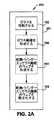
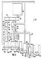
図1A及び図3Aは、繊維材料からパック300(図3A参照)を形成する連続プロセス又は方法100の第1の例示の実施形態を示している。方法100のステップの周りに描かれた破線101は、この方法が以下に詳細に説明するように連続方法であることを意味している。方法及びパックをガラス繊維の観点で説明するが、これら方法及びパックは、他の鉱物、例えば非限定的な例として岩石、スラグ及び玄武岩で作られた繊維製品の製造にも利用できる。 1A and 3A illustrate a first exemplary embodiment of a continuous process or
図1Aを参照すると、ガラスを溶融させる(102)。例えば、図3Aは、溶融室314を概略的に示している。溶融室314は、溶融ガラス312をフォアハース316に供給することができる。溶融室及びフォアハースは、当該技術分野において知られており、ここではこれらについては説明しない。溶融ガラス312は、所望の化学組成物を与えるような比率で組み合わされた種々の原料で作られるのが良い。 Referring to FIG. 1A, the glass is melted (102). For example, FIG. 3A schematically illustrates the
図1Aに戻ってこれを参照すると、溶融ガラス312を処理してガラス繊維322を形成する(104)。繊維322を形成するのに溶融ガラス312を多種多様な仕方で処理することができる。例えば、図3Aに示された実施例では、溶融ガラス312は、フォアハース316から1つ又は2つ以上の回転繊維化装置318に流れる。回転繊維化装置318は、溶融ガラス312を受け入れ、次に、ガラス繊維322のベール320を形成する。以下に詳細に説明するように、回転繊維化装置318によって形成されたガラス繊維322は、長く且つ細い。したがって、長く且つ細いガラス繊維322を形成するのに十分な任意所望の繊維化装置(回転式又はその他の形式のもの)を用いることができる。図3Aに示された実施形態は、1つの回転繊維化装置318を示しているが、理解されるべきこととして、任意所望の数の回転繊維化装置318を使用することができる。 Referring back to FIG. 1A, the
長く且つ細い繊維は、多種多様な形態を取ることができる。例示の実施形態では、長く且つ細い繊維は、約0.25インチ(0.64cm)から約10.0インチ(25.40cm)までの範囲の長さ及び約9HTから約35HTまでの範囲の直径寸法を有する。HTは、1インチ(2.54cm)の10万分の1を表している。例示の実施形態では、繊維322は、約1.0インチ(2.54cm)から約5.0インチ(12.70cm)までの範囲の長さ及び約14HTから約25HTまでの範囲の直径寸法を有する。例示の実施形態では、繊維322は、約3インチ(7.62cm)の長さ及び約16〜17HTの平均直径を有する。理論に束縛されるものではないが、比較的長く且つ細い繊維の使用は、有利には、良好な断熱性能及び防音性能並びに良好な強度特性、例えば短く且つ太い繊維を有する類似のサイズのパックよりも高い引張り強度及び/又は高い結合強度をもたらすことが考えられる。 Long and thin fibers can take a wide variety of forms. In an exemplary embodiment, the long and thin fibers have a length ranging from about 0.25 inches (0.64 cm) to about 10.0 inches (25.40 cm) and a diameter ranging from about 9 HT to about 35 HT. Have dimensions. HT represents 1 / 100,000 of 1 inch (2.54 cm). In the illustrated embodiment, the
本明細書において説明する例示の実施形態では、ガラス繊維322は、ガラス繊維を形成した後に潤滑剤でオプションとして被覆され又は部分的に被覆されるのが良い。例えば、ガラス繊維322は、ガラス繊維を互いに結合することがない潤滑減摩性材料で被覆されるのが良い。例示の実施形態では、潤滑剤は、シリコーン化合物、例えばシロキサン、ジメチルシロキサン及び/又はシランであるのが良い。潤滑剤は、他の物質又は物質の組み合わせ、例えば油又は油乳濁液であっても良い。油又は油乳濁液は、鉱物油又は鉱物油乳濁液及び/又は植物油又は植物油乳濁液であるのが良い。 In the exemplary embodiments described herein, the
ガラス繊維を多種多様な仕方により潤滑剤で被覆し又は部分的に被覆することができる。例えば、潤滑剤をガラス繊維322に吹き付けることができる。例示の実施形態では、潤滑剤は、ガラス繊維322が製造プロセスを通って移動して種々の装置及び/又は他のガラス繊維に接触する際のガラス繊維322に対する損傷を阻止するよう構成されている。潤滑剤は又、製造プロセス中のダストを減少させるのに有益な場合がある。オプションとしての潤滑剤の塗布は、任意所望の構造体、機構体又は装置によって正確に制御されるのが良い。 Glass fibers can be coated or partially coated with a lubricant in a wide variety of ways. For example, a lubricant can be sprayed onto the
図1Aを参照すると、バインダー又は繊維を互いに結合する他の物質が含まれない繊維のウェブ321を形成する(106)。ウェブ321を多種多様な仕方で形成することができる。図3Aに示された実施例では、ガラス繊維322をオプションとしての収集部材324により集める。収集部材324は、ガラス繊維322を受け入れるような寸法形状のものである。収集部材324は、ガラス繊維322を下流側の処理ステーション、例えば形成装置332への移送のためにダクト330にそらすよう構成されており、形成装置332は、ウェブ321を形成する。他の実施形態では、ガラス繊維322を運搬機構体(図示せず)上に収集してウェブを形成しても良い。 Referring to FIG. 1A, a web of
形成装置332は、所望の厚さを有する繊維材料の連続乾燥ウェブ321を形成するよう構成されているのが良い。例示の一実施形態では、本願において開示される乾燥ウェブ321は、約0.25インチ(0.64cm)から約4インチ(10.16cm)までの範囲の厚さ及び約0.2ポンド/立方フィート(3.206kg/m3)から約0.6ポンド/立方フィート(9.618kg/m3)までの範囲の密度を有するのが良い。例示の一実施形態では、本願において開示される乾燥ウェブ321は、約1インチ(2.54cm)から約3インチ(7.62cm)までの範囲の厚さ及び約0.3ポンド/立方フィート(4.809kg/m3)から約0.5ポンド/立方フィート(8.015kg/m3)までの範囲の密度を有するのが良い。例示の一実施形態では、本願において開示される乾燥ウェブ321は、約1.5インチ(3.81cm)の厚さ及び約0.4ポンド/立方フィート(6.412kg/m3)の密度を有するのが良い。形成装置332は、多種多様な形態を取ることができる。ガラス繊維の乾燥ウェブ321を形成する任意の構成例を使用することができる。The forming
例示の一実施形態では、形成装置332は、形成面及び高い又は低い圧力の領域を備えた回転ドラムを有する。図4を参照すると、繊維322が集められる形成面部462の片面460に加わる圧力P1は、反対側の片面464に加わる圧力P2よりも高い。この圧力降下ΔPにより、繊維322は、形成面部462上に集まって乾燥ウェブ321を形成する。例示の一実施形態では、形成面部462前後の圧力降下ΔPは、低い圧力であって低面積重量ウェブを作るよう制御される。例えば、圧力降下ΔPは、水柱約0.5インチ(1.27cm)〜30インチ(76.20cm)であるのが良い。結果的にこの低い圧力降下ΔPをもたらす形成中のウェブを通って流れる空気の速度Vは、毎分最大1,000フィート(304.8m)であるのが良い。 In one exemplary embodiment, the forming
低面積重量ウェブ321は、1平方フィート(0.0929m2)当たり約5〜約50グラムの面積重量を有する。低面積重量ウェブは、上述の範囲の密度及び厚さを有するのが良い。低面積重量ウェブは、約0.25インチ(0.64cm)から約4インチ(10.16cm)までの範囲、約1インチ(2.54cm)から約3インチ(7.62cm)までの範囲、又は約1.5インチ(3.81cm)の厚さを有するのが良い。低面積重量ウェブは、約0.2ポンド/立方フィート(3.206kg/m3)から約0.6ポンド/立方フィート(9.618kg/m3)、約0.3ポンド/立方フィート(4.809kg/m3)から約0.5ポンド/立方フィート(8.015kg/m3)又は約0.4ポンド/立方フィート(6.412kg/m3)の密度を有するのが良い。図3Aを参照すると、乾燥ウェブ321は、形成装置332を出る。例示の一実施形態では、低面積重量ウェブ321は、0〜40%の測定面積重量分布変動係数=シグマ(1標準偏差)/平均値(平均)×100%。例示の実施形態では、重量分布変動係数は、30%未満、20%未満又は10%未満である。例示の一実施形態では、重量分布変動係数は、25%〜30%、例えば約28%である。例示の一実施形態では、重量分布変動係数は、約28%である。重量分布変動係数は、ライトテーブルを用いて大きなサンプル、例えば6フィート(1.82m)×10フィート(3.04m)のサンプルの多くの小さなサンプル面積サイズ、例えば2インチ(5.08cm)×2インチ(5.08cm)を測定することによって得られる。The low
図1Aに示された実施例では、ウェブ321又は多数のウェブを層状にする(108)。例えば、単一のウェブ321を縦方向に重ね又は縦方向に対して90°の角度をなして交差重ねして層状ウェブ350を形成するのが良い。別の実施形態では、ウェブを部分部分に切断し、これら部分を互いに上下に積み重ねて層状ウェブを形成しても良い。さらに別の例示の実施形態では、1つ又は2つ以上の二重繊維化装置318及び形成装置332を2つ又は3つ以上のウェブが平行に連続製造されるよう具体化することができる。次に、平行なウェブを互いに上下に積み重ねて層状ウェブを形成する。 In the embodiment shown in FIG. 1A, the
例示の一実施形態では、形成装置又は層状化機構体332は、コンベヤ336と関連して機能する重ね機構体又は交差重ね機構体である。コンベヤ336は、矢印D1で示されている縦方向に動くよう構成されている。重ね又は交差重ね機構体は、連続ウェブ321を受け入れて第1のコンベヤが縦方向D1に動いているときに第1のコンベヤ336上に連続ウェブの交互の層を堆積させるよう構成されている。堆積プロセスでは、重ね機構体334は、矢印D1で示されている縦方向に交互の層を形成し又は交差重ね機構体334は、横方向に交互の層を形成する。追加のウェブ321を形成して追加の重ね又は交差重ね機構体によって重ね又は交差重ねすると、層の数を増やすと共にスループット性能を向上させることができる。 In one exemplary embodiment, the forming device or
例示の一実施形態では、交差重ね機構体は、連続ウェブ321の運動を正確に制御し、この連続ウェブをコンベヤ336上に堆積させて連続ウェブが損傷を受けないようにするよう構成されている。交差重ね機構体は、任意所望の構造体を有することができ、かかる交差重ね機構体は、任意所望の仕方で作動するよう構成可能である。例示の一実施形態では、交差重ね機構体は、縦方向D1に対して90°前後に動くよう構成されたヘッド(図示せず)を含む。この実施形態では、可動ヘッドの速度は、両方の横方向におけるヘッドの運動が実質的に同じであるよう協調され、それにより、結果として得られる繊維本体の層の一様性が提供される。例示の実施形態では、交差重ね機構体は、コンベヤ336の中心線に心出しされるよう構成された垂直コンベヤ(図示せず)を含む。垂直コンベヤは、連続ウェブをコンベヤ336上に堆積させるようコンベヤ336上に設けられたピボット機構体から揺動するよう更に構成されている。交差重ね機構体の多数の実施例について上述したが、理解されるべきこととして、交差重ね機構体は、他の構造体、機構体若しくは装置又はこれらの組み合わせであっても良い。 In one exemplary embodiment, the cross-over mechanism is configured to accurately control the movement of the
層状ウェブ350は、任意所望の厚さを有することができる。層状ウェブの厚さは、幾つかの変数の関数である。第1に、層状ウェブ350の厚さは、形成装置332によって形成される連続ウェブ321の厚さの関数である。第2に、層状ウェブ350の厚さは、層状化機構体334が連続ウェブ321の層をコンベヤ336上に堆積させる速度の関数である。第3に、層状ウェブ350の厚さは、コンベヤ336の速度の関数である。図示の実施形態では、層状ウェブ350は、約0.1インチ(0.25cm)から約20.0インチ(50.80cm)までの範囲の厚さを有する。例示の実施形態では、交差重ね機構体334は、1つから60個の層を有する層状ウェブ350を形成することができる。オプションとして、交差重ね機構体は、調節可能であるのが良く、それにより交差重ね機構体334が任意所望の幅を有するパックを形成することができる。或る特定の実施形態では、パックは、約98.0インチ(248.92cm)から約236.0インチ(599.44cm)までの範囲の全体的幅を有するのが良い。 The
例示の一実施形態では、層状ウェブ350は、図1Aに破線のボックス101で示された連続プロセスで製造される。繊維化装置318によって製造された繊維を直接形成装置332に送る(即ち、繊維を集めないで包装し、次に、遠隔の形成装置での使用のために包装を解く)。ウェブ321を直接層状化装置352に提供する(即ち、ウェブを形成しないで巻き取り、次に遠隔の層状化装置352のところで使用するために巻き出す)。連続プロセスの例示の実施形態では、これらのプロセスのうちの各々(図1Aの形成及び層状化)は、繊維化プロセスに結合されており、その結果、繊維化装置からの繊維は、後で使用するために貯蔵されるのではなく、他のプロセスによって使用されるようになっている。 In one exemplary embodiment, the
例示の一実施形態では、ウェブ321は、比較的厚く、しかも低い面積重量を有し、更に、連続方法は、高いスループットをもたらす。例えば、ウェブ321の単一の層は、1平方フィート(0.0929m2)当たり約5〜約50グラムの面積重量を有するのが良い。低面積重量ウェブは、上述した密度範囲及び厚さ範囲を有するのが良い。高出力連続プロセスは、約750ポンド/時(340.2kg/時)〜1500ポンド/時(680.4kg/時)、例えば少なくとも900ポンド/時(408.2kg/時)又は少なくとも1250ポンド/時(567.0kg/時)を生じさせることができる。層状ウェブ350を多種多様な用途で用いることができる。In one exemplary embodiment, the
図1B及び図3Bは、バインダーを使用しないで繊維材料からパック300(図3B参照)を形成する第2の例示の実施形態としての方法150を示している。方法150のステップの周りに描かれた破線151は、この方法が連続方法であることを示している。図1Bを参照すると、ガラスを溶融させる(102)。ガラスは、図3Aを参照して上述したように溶融されるのが良い。溶融ガラス312を処理してガラス繊維322を形成する(104)。ガラス繊維322を形成するために図3Aを参照して上述したように溶融ガラス312を処理するのが良い。バインダー又はガラス繊維を互いに結合する他の物質を含まない繊維のウェブ321を形成する(106)。図3Aを参照して上述したようにウェブ321を形成するのが良い。 1B and 3B illustrate a second
図1Bを参照すると、ウェブ321の繊維322を機械的に絡ませて(202)、絡み合った状態のウェブ352(図3B参照)を形成する。図3Bを参照すると、ウェブ321の繊維を絡ませ機構体345、例えばニードリング装置によって機械的に絡ませるのが良い。絡ませ機構体345は、ウェブ321の個々の繊維322を絡ませるよう構成されている。ガラス繊維322を絡ませることにより、ウェブの繊維を互いに結びつける。絡み合いにより、ウェブの機械的性質、例えば引張り強度及び剪断強度を向上させる。図示の実施形態では、絡ませ機構体345は、ニードリング機構体である。他の実施形態では、絡ませ機構体345は、他の構造体、機構体若しくは装置又はこれらの組み合わせを含むのが良く、かかる機構体としては非限定的な例として、縫合機構体が挙げられる。 Referring to FIG. 1B, the
絡み合いウェブ352は、任意所望の厚さを有することができる。絡み合いウェブの厚さは、形成装置332により形成される連続ウェブ321の厚さ及び絡ませ機構体345による連続ウェブ321の圧縮量の関数である。例示の実施形態では、絡み合いウェブ352は、約0.1インチ(0.25cm)から約2.0インチ(5.08cm)までの範囲の厚さを有する。例示の実施形態では、絡み合いウェブ352は、約0.5インチ(1.27cm)から約1.75インチ(4.45cm)までの範囲の厚さを有する。例えば、例示の一実施形態では、絡み合いウェブの厚さは、約1/2インチ(1.27cm)である。 The
例示の一実施形態では、絡み合いウェブ352を連続プロセス151で製造する。繊維化装置318により製造された繊維を直接、形成装置332に送る(即ち、ガラス繊維を集めないで包装し、次に遠隔の形成装置での使用のために包装を解く)。ウェブ321を直接、絡ませ装置345に提供する(即ち、ウェブを形成しないで巻き取り、次に遠隔の絡ませ装置345のところで使用できるよう巻き出す)。絡み合いウェブ352を多種多様な用途で使用することができる。連続プロセスの例示の実施形態では、プロセス(図1Bの形成及び絡ませ)の各々を繊維化プロセスに結合し、その結果、繊維化装置からの繊維を後で使用するために貯蔵することなく、他のプロセスによって使用するようにする。 In one exemplary embodiment, the
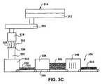
図1C及び図3Cは、バインダーを使用しないで繊維材料からパック370(図3C参照)を形成する第3の例示の実施形態としての方法170を示している。図1Cを参照すると、ガラスを溶融させる(102)。方法170のステップの周りに描かれた破線171は、この方法が連続方法であることを示している。図3Aを参照して上述したようにガラスを溶融させるのが良い(102)。図1Cに戻ってこれを参照すると、溶融ガラス312を処理してガラス繊維322を形成する(104)。ガラス繊維322を形成するために図3Aを参照して上述したように溶融ガラス312を処理するのが良い。図1Cを参照すると、バインダー又はガラス繊維を互いに結合する他の物質を含まない繊維のウェブ321を形成する(106)。図3Aを参照して上述したようにウェブ321を形成するのが良い。図1Cを参照すると、ウェブ321又は多数のウェブを層状にする(108)。図3Aを参照して上述したようにウェブ321又は多数のウェブを層状にするのが良い。図1Cを参照すると、層状ウェブ350の繊維322を機械的に絡ませて(302)、層状ウェブの絡み合いパック370を形成する。 1C and 3C illustrate a third
図3Cを参照すると、層状ウェブ350の繊維を絡ませ機構体345、例えばニードリング装置によって機械的に絡ませるのが良い。絡ませ機構体345は、層状ウェブの層を形成する個々の繊維322を絡ませるよう構成されている。ガラス繊維322を絡ませることにより、層状ウェブの繊維を互いに結びつける。機械的絡み合いにより、機械的性質、例えば引張り強度及び剪断強度を向上させる。図示の実施形態では、絡ませ機構体345は、ニードリング機構体である。他の実施形態では、絡ませ機構体345は、他の構造体、機構体若しくは装置又はこれらの組み合わせを含むのが良く、かかる機構体としては非限定的な例として、縫合機構体が挙げられる。 Referring to FIG. 3C, the fibers of the
層状ウェブ350の絡み合いパック370は、任意所望の厚さを有することができる。絡み合いパックの厚さは、幾つかの変数の関数である。第1に、絡み合いパックの厚さは、形成装置332によって形成される連続ウェブ321の厚さの関数である。第2に、絡み合いパック370の厚さは、重ね機構体又は交差重ね機構体334が連続ウェブ321の層をコンベヤ336上に堆積させる速度の関数である。第3に、絡み合いパック370の厚さは、コンベヤ336の速度の関数である。第4に、絡み合いパック370の厚さは、絡ませ機構体345による層状ウェブ350の圧縮量の関数である。絡み合いパック370は、約0.1インチ(0.25cm)から約20.0インチ(50.80cm)までの範囲の厚さを有するのが良い。例示の実施形態では、絡み合いパック370は、1つから60個の層を有するのが良い。各絡み合いウェブ層352は、厚さが0.1インチ(0.25cm)〜2インチ(5.08cm)であるのが良い。例えば、各絡み合いウェブ層の厚さは、約0.5インチ(1.27cm)であるのが良い。 The entangled pack 370 of the
例示の一実施形態では、絡み合いパック370を連続プロセスで製造する。繊維化装置318により製造された繊維を形成装置332に直接送る(即ち、ガラス繊維を集めないで包装し、次に遠隔の形成装置での使用のために包装を解く)。ウェブ321を絡ませ装置345に直接提供する(即ち、ウェブを形成しないで巻き取り、次に遠隔の層状化装置352のところで使用できるよう巻き出す)。層状ウェブ350を絡ませ装置345に直接提供する(即ち、層状ウェブを形成しないで巻き取り、次に遠隔の層状化装置352のところで使用できるよう巻き出す)。連続プロセスの例示の実施形態では、プロセス(図1Cの形成、層状化及び絡ませ)の各々を繊維化プロセスに結合し、その結果、繊維化装置からの繊維を後で使用するために貯蔵することなく、他のプロセスによって使用するようにする。 In one exemplary embodiment, the intertwined pack 370 is manufactured in a continuous process. The fibers produced by the
例示の一実施形態では、層状ウェブの絡み合いパック370は、比較的厚く、そして低い面積重量を有するウェブ321又は多数のウェブで作られており、更に、連続プロセスは、高いスループットをもたらす。例えば、ウェブ321の単一の層は、上述した面積重量、厚さ及び密度を有するのが良い。高出力連続プロセスは、約750ポンド/時(340.2kg/時)〜1500ポンド/時(680.4kg/時)、例えば少なくとも900ポンド/時(408.2kg/時)又は少なくとも1250ポンド/時(567.0kg/時)を生じさせることができる。例示の実施形態では、連続プロセスの高いウェブスループットと機械的絡み合い、例えばニードリングの組み合わせは、ウェブ321の層状化、例えばウェブの重ね又は交差重ねによって容易になる。ウェブ321を層状にすることによって、層状化装置を通って移動する材料の線速度は、ウェブの形成速度よりも遅い。例えば、連続プロセスでは、二層ウェブがウェブの形成速度の1/2の速度で絡ませ装置345を通って動く(3つの層‐速度の1/3等)。速度のこの減少は、高いスループット且つ低面積重量のウェブ321を形成して多層の機械的に絡み合ったパック370に変換する連続プロセスを計算に入れている。層状ウェブの絡み合いパック370を多種多様な用途で用いることができる。 In one exemplary embodiment, the layered web entanglement pack 370 is made of a
例示の実施形態では、長くて細いガラス繊維の層状化及び絡み合いの結果として、強固なウェブ370が得られる。例えば、本願において説明する長くて細いガラス繊維の絡み合いの結果として、高い引張り強度及び高い結合強度を備えた層状絡み合いウェブが得られる。引張り強度は、ウェブがウェブの長さ又は幅の方向に引かれたときのウェブ370の強度である。結合強度は、ウェブ370がウェブの厚さの方向に引き離されたときのウェブの強度である。 In the illustrated embodiment, a rigid web 370 is obtained as a result of the layering and entanglement of long and thin glass fibers. For example, as a result of the long and thin glass fiber entanglement described herein, a layered entangled web with high tensile strength and high bond strength is obtained. Tensile strength is the strength of the web 370 when the web is pulled in the length or width direction of the web. The bond strength is the strength of the web when the web 370 is pulled away in the direction of the web thickness.
引張り強度及び結合強度を多種多様な仕方で試験することができる。例示の一実施形態では、機械、例えばインストロン(Instron)機械がウェブ370を固定された速度(以下に説明する実施例では、1秒当たり12インチ(30.48cm))で引き離し、ウェブを引き離すのに必要な力の大きさを測定する。ウェブを引き離すのに必要な力(ウェブが裂け又は破れる前にウェブに加えられたピーク力を含む)を記録する。 Tensile strength and bond strength can be tested in a wide variety of ways. In one exemplary embodiment, a machine, such as an Instron machine, pulls the web 370 apart at a fixed speed (12 inches (30.48 cm) in the example described below) and pulls the web apart. Measure the amount of force required to Record the force required to pull the web apart (including the peak force applied to the web before it tears or tears).
引張り強度を試験する一方法では、ウェブの幅に沿ってウェブの端部をクランプし、ウェブ370を機械でウェブの長さに沿って一定の速度(以下に提供する実施例では1秒当たり12インチ(30.48cm))で引っ張り、そしてウェブの長さ方向に加えられたピーク力を記録することによって、引張り強度を測定する。ウェブの幅に沿ってウェブの端部をクランプし、ウェブ370をウェブの幅に沿って一定の速度(以下に提供する実施例では1秒当たり12インチ(30.48cm))で引っ張り、そして加えられたピーク力を記録することによって幅方向における引張り強度を測定する。長さ方向における引張り強度と幅方向における引張り強度を平均してサンプルの引張り強度を求める。 One method of testing tensile strength is to clamp the edge of the web along the width of the web and machine the web 370 at a constant speed along the length of the web (12 / second in the example provided below). Tensile strength is measured by pulling in inches (30.48 cm)) and recording the peak force applied along the length of the web. Clamp the edge of the web along the width of the web, pull the web 370 along the width of the web at a constant speed (12 inches (30.48 cm) in the example provided below) and add The tensile strength in the width direction is measured by recording the resulting peak force. The tensile strength of the sample is obtained by averaging the tensile strength in the length direction and the tensile strength in the width direction.
結合強度を試験する一方法では、所定サイズ(以下に説明する実施例では6インチ(15.24cm)×6インチ(15.24cm))のサンプルを用意する。サンプルの各側を例えば糊付けによって基板に結合する。サンプルの反対側の基板を機械により一定速度(以下に提供する実施例では1秒当たり12インチ(30.48cm))で引き離し、加えられたピーク力を記録する。加えたピーク力をサンプルの面積(以下に説明する実施例では6インチ(15.24cm)×6インチ(15.24cm))の面積で除算して力/面積で表した結合強度を求める。 One method of testing bond strength is to prepare a sample of a predetermined size (6 inches (15.24 cm) x 6 inches (15.24 cm) in the examples described below). Each side of the sample is bonded to the substrate, for example by gluing. The substrate on the opposite side of the sample is pulled apart by a machine at a constant speed (12 inches (30.48 cm) in the example provided below) and the applied peak force is recorded. The applied peak force is divided by the area of the sample (6 inches (15.24 cm) × 6 inches (15.24 cm) in the examples described below) to determine the bond strength in force / area.
以下の実施例は、層状絡み合いウェブ370の強度の増大を示すために提供されている。これら実施例では、バインダーが含まれていない。すなわち、非水性又は乾燥バインダーが含まれる。これら実施例は、特許請求の範囲に明示の記載がない場合、本発明の範囲を制限するものではない。4つ、6つ及び8つの層を有する層状絡み合いウェブの実施例を用意する。しかしながら、層状絡み合いウェブ370は、任意の数の層を備えることができる。層状絡み合いウェブ370のサンプル長さ、幅、厚さ、ラップの数及び重量は、ウェブ370の用途に応じて様々であって良い。 The following examples are provided to illustrate the increased strength of the layered entangled web 370. In these examples, no binder is included. That is, non-aqueous or dry binders are included. These examples do not limit the scope of the invention, unless explicitly stated in the claims. Examples of layered entangled webs with 4, 6 and 8 layers are provided. However, the layered entangled web 370 can comprise any number of layers. The sample length, width, thickness, number of wraps and weight of the layered entangled web 370 may vary depending on the application of the web 370.
例示の一実施形態では、6インチ(15.24cm)×12インチ(30.48cm)のウェブ370のサンプルは、多数の層を有し、例えば2つのラップ(即ち、4つの層)の厚さは、0.5インチ(1.27cm)〜2.0インチ(5.08cm)であり、その1平方フィート(0.093m2)当たりの重量は、0.1〜0.3ポンド/平方フィート(0.49〜1.46kg/m2)であり、その引張り強度は、3ポンド/平方フィート(14.6kg/m2)を超え、引張り強度と重量の比は、40(lbf/lbm)を超え、例えば約40〜約120(lbf/lbm)である。例示の実施形態では、このサンプルの結合強度は、0.1ポンド/平方フィート(0.49kg/m2)を超える(なお、1インチは、2.54cmであり、1ポンド/平方フィートは、4.9kg/m2である)。例示の実施形態では、この段落で説明しているサンプルの引張り強度は、5ポンド/平方フィート(24.4kg/m2)を超える。例示の実施形態では、この段落で説明しているサンプルの引張り強度は、7.5ポンド/平方フィート(36.6kg/m2)を超える。例示の実施形態では、この段落で説明しているサンプルの引張り強度は、10ポンド/平方フィート(48.8kg/m2)を超える。例示の実施形態では、この段落で説明しているサンプルの引張り強度は、12.5ポンド/平方フィート(61kg/m2)を超える。例示の実施形態では、この段落で説明しているサンプルの引張り強度は、13.75ポンド/平方フィート(67.1kg/m2)を超える。例示の実施形態では、この段落で説明しているサンプルの引張り強度は、3〜15ポンド/平方フィート(14.6〜73.2kg/m2)である。例示の実施形態では、この段落で説明しているサンプルの結合強度は、2ポンド/平方フィート(9.76kg/m2)を超える。例示の実施形態では、この段落で説明しているサンプルの結合強度は、5ポンド/平方フィート(24.4kg/m2)を超える。例示の実施形態では、この段落で説明しているサンプルの結合強度は、10ポンド/平方フィート(48.8kg/m2)を超える。例示の実施形態では、この段落で説明しているサンプルの結合強度は、15ポンド/平方フィート(73.2kg/m2)を超える。例示の実施形態では、この段落で説明しているサンプルの結合強度は、20ポンド/平方フィート(97.6kg/m2)を超える。例示の実施形態では、この段落で説明しているサンプルの引張り強度は、5ポンド/平方フィート(24.4kg/m2)を超え、結合強度は、2ポンド/平方フィート(9.76kg/m2)を超える。例示の実施形態では、この段落で説明しているサンプルの引張り強度は、7.5ポンド/平方フィート(36.6kg/m2)を超え、結合強度は、7.5ポンド/平方フィート(36.6kg/m2)を超える。例示の実施形態では、この段落で説明しているサンプルの引張り強度は、10ポンド/平方フィート(48.8kg/m2)を超え、結合強度は、10ポンド/平方フィート(48.8kg/m2)を超える。例示の実施形態では、この段落で説明しているサンプルの引張り強度は、12.5ポンド/平方フィート(61kg/m2)を超え、結合強度は、15ポンド/平方フィート(73.2kg/m2)を超える。例示の実施形態では、この段落で説明しているサンプルの引張り強度は、13.75ポンド/平方フィート(67.1kg/m2)を超え、結合強度は、20ポンド/平方フィート(97.6kg/m2)を超える。例示の実施形態では、この段落で説明しているサンプルの引張り強度は、3〜15ポンド/平方フィート(14.6〜73.2kg/m2)であり、結合強度は、0.3〜30ポンド/平方フィート(1.46〜146.4kg/m2)である。In one exemplary embodiment, a 6 inch (15.24 cm) by 12 inch (30.48 cm) web 370 sample has multiple layers, eg, two wraps (ie, four layers) thick. Is 0.5 inch (1.27 cm) to 2.0 inch (5.08 cm), and its weight per square foot (0.093 m2 ) is 0.1 to 0.3 pounds per square foot (0.49 to 1.46 kg / m2 ), its tensile strength exceeds 3 pounds per square foot (14.6 kg / m2 ), and the ratio of tensile strength to weight is 40 (lbf / lbm) For example about 40 to about 120 (lbf / lbm). In an exemplary embodiment, the bond strength of this sample is greater than 0.1 pounds per square foot (0.49 kg / m2 ) (note that 1 inch is 2.54 cm and 1 pound per square foot is 4.9 kg / m2 ). In an exemplary embodiment, the tensile strength of the sample described in this paragraph is greater than 5 pounds per square foot (24.4 kg / m2 ). In an exemplary embodiment, the tensile strength of the sample described in this paragraph is greater than 7.5 pounds per square foot (36.6 kg / m2 ). In an exemplary embodiment, the tensile strength of the sample described in this paragraph is greater than 10 pounds per square foot (48.8 kg / m2 ). In the exemplary embodiment, the tensile strength of the sample described in this paragraph is greater than 12.5 pounds per square foot (61 kg / m2 ). In the illustrated embodiment, the tensile strength of the sample described in this paragraph is greater than 13.75 pounds per square foot (67.1 kg / m2 ). In an exemplary embodiment, the tensile strength of the sample described in this paragraph is 3 to 15 pounds per square foot (14.6 to 73.2 kg / m2 ). In the exemplary embodiment, the binding strength of the sample described in this paragraph is greater than 2 pounds per square foot (9.76 kg / m2 ). In the exemplary embodiment, the binding strength of the sample described in this paragraph is greater than 5 pounds per square foot (24.4 kg / m2 ). In the exemplary embodiment, the binding strength of the sample described in this paragraph is greater than 10 pounds per square foot (48.8 kg / m2 ). In the exemplary embodiment, the binding strength of the sample described in this paragraph is greater than 15 pounds per square foot (73.2 kg / m2 ). In the exemplary embodiment, the binding strength of the sample described in this paragraph is greater than 20 pounds per square foot (97.6 kg / m2 ). In an exemplary embodiment, the tensile strength of the sample described in this paragraph exceeds 5 pounds per square foot (24.4 kg / m2 ) and the bond strength is 2 pounds per square foot (9.76 kg / m2 ).2 ) is exceeded. In an exemplary embodiment, the tensile strength of the sample described in this paragraph is greater than 7.5 pounds per square foot (36.6 kg / m2 ) and the bond strength is 7.5 pounds per square foot (36 .6 kg / m2 ). In an exemplary embodiment, the tensile strength of the sample described in this paragraph exceeds 10 pounds per square foot (48.8 kg / m2 ) and the bond strength is 10 pounds per square foot (48.8 kg / m2 ).2 ) is exceeded. In an exemplary embodiment, the tensile strength of the sample described in this paragraph is greater than 12.5 pounds / square foot (61 kg / m2 ) and the bond strength is 15 pounds / square foot (73.2 kg / m2 ).2 ) is exceeded. In an exemplary embodiment, the tensile strength of the sample described in this paragraph is greater than 13.75 pounds per square foot (67.1 kg / m2 ) and the bond strength is 20 pounds per square foot (97.6 kg). / M2 ). In an exemplary embodiment, the tensile strength of the sample described in this paragraph is 3-15 pounds per square foot (14.6-73.2 kg / m2 ) and the bond strength is 0.3-30. Pounds per square foot (1.46 to 146.4 kg / m2 ).
例示の一実施形態では、6インチ(15.24cm)×12インチ(30.48cm)のウェブ370のサンプルは、多数の層を有し、例えば2つのラップ(即ち、4つの層)の厚さは、0.5インチ(1.27cm)〜1.75インチ(4.445cm)であり、その1平方フィート(0.093m2)当たりの重量は、0.12〜0.27ポンド/平方フィート(0.5856〜1.1376kg/m2)であり、その引張り強度は、3ポンド/平方フィート(14.6kg/m2)を超え、引張り強度と重量の比は、40(lbf/lbm)を超え、例えば約40〜約120(lbf/lbm)であり、結合強度は、1ポンド/平方フィート(4.88kg/m2)を超える。例示の実施形態では、この段落で説明しているサンプルの引張り強度は、5ポンド/平方フィート(24.4kg/m2)を超える。例示の実施形態では、この段落で説明しているサンプルの引張り強度は、7.5ポンド/平方フィート(36.6kg/m2)を超える。例示の実施形態では、この段落で説明しているサンプルの引張り強度は、10ポンド/平方フィート(48.8kg/m2)を超える。例示の実施形態では、この段落で説明しているサンプルの引張り強度は、12.5ポンド/平方フィート(61kg/m2)を超える。例示の実施形態では、この段落で説明しているサンプルの引張り強度は、13.75ポンド/平方フィート(67.1kg/m2)を超える。例示の実施形態では、この段落で説明しているサンプルの引張り強度は、3〜15ポンド/平方フィート(14.6〜73.2kg/m2)である。例示の実施形態では、この段落で説明しているサンプルの結合強度は、2ポンド/平方フィート(9.76kg/m2)を超える。例示の実施形態では、この段落で説明しているサンプルの結合強度は、5ポンド/平方フィート(24.4kg/m2)を超える。例示の実施形態では、この段落で説明しているサンプルの結合強度は、10ポンド/平方フィート(48.8kg/m2)を超える。例示の実施形態では、この段落で説明しているサンプルの結合強度は、15ポンド/平方フィート(73.2kg/m2)を超える。例示の実施形態では、この段落で説明しているサンプルの結合強度は、20ポンド/平方フィート(97.6kg/m2)を超える。例示の実施形態では、この段落で説明しているサンプルの引張り強度は、5ポンド/平方フィート(24.4kg/m2)を超え、結合強度は、2ポンド/平方フィート(9.76kg/m2)を超える。例示の実施形態では、この段落で説明しているサンプルの引張り強度は、7.5ポンド/平方フィート(36.6kg/m2)を超え、結合強度は、7.5ポンド/平方フィート(36.6kg/m2)を超える。例示の実施形態では、この段落で説明しているサンプルの引張り強度は、10ポンド/平方フィート(48.8kg/m2)を超え、結合強度は、10ポンド/平方フィート(48.8kg/m2)を超える。例示の実施形態では、この段落で説明しているサンプルの引張り強度は、12.5ポンド/平方フィート(61kg/m2)を超え、結合強度は、15ポンド/平方フィート(73.2kg/m2)を超える。例示の実施形態では、この段落で説明しているサンプルの引張り強度は、13.75ポンド/平方フィート(67.1kg/m2)を超え、結合強度は、20ポンド/平方フィート(97.6kg/m2)を超える。例示の実施形態では、この段落で説明しているサンプルの引張り強度は、3〜15ポンド/平方フィート(14.6〜73.2kg/m2)であり、結合強度は、0.3〜30ポンド/平方フィート(1.46〜146.4kg/m2)である。In one exemplary embodiment, a 6 inch (15.24 cm) by 12 inch (30.48 cm) web 370 sample has multiple layers, eg, two wraps (ie, four layers) thick. Is 0.5 inches (1.27 cm) to 1.75 inches (4.445 cm), and its weight per square foot (0.093 m2 ) is 0.12 to 0.27 pounds per square foot (0.5856-1.1376 kg / m2 ), its tensile strength is over 3 pounds per square foot (14.6 kg / m2 ), and the ratio of tensile strength to weight is 40 (lbf / lbm) For example, from about 40 to about 120 (lbf / lbm), and the bond strength is greater than 1 pound per square foot (4.88 kg / m2 ). In an exemplary embodiment, the tensile strength of the sample described in this paragraph is greater than 5 pounds per square foot (24.4 kg / m2 ). In an exemplary embodiment, the tensile strength of the sample described in this paragraph is greater than 7.5 pounds per square foot (36.6 kg / m2 ). In an exemplary embodiment, the tensile strength of the sample described in this paragraph is greater than 10 pounds per square foot (48.8 kg / m2 ). In the exemplary embodiment, the tensile strength of the sample described in this paragraph is greater than 12.5 pounds per square foot (61 kg / m2 ). In the illustrated embodiment, the tensile strength of the sample described in this paragraph is greater than 13.75 pounds per square foot (67.1 kg / m2 ). In an exemplary embodiment, the tensile strength of the sample described in this paragraph is 3 to 15 pounds per square foot (14.6 to 73.2 kg / m2 ). In the exemplary embodiment, the binding strength of the sample described in this paragraph is greater than 2 pounds per square foot (9.76 kg / m2 ). In the exemplary embodiment, the binding strength of the sample described in this paragraph is greater than 5 pounds per square foot (24.4 kg / m2 ). In the exemplary embodiment, the binding strength of the sample described in this paragraph is greater than 10 pounds per square foot (48.8 kg / m2 ). In the exemplary embodiment, the binding strength of the sample described in this paragraph is greater than 15 pounds per square foot (73.2 kg / m2 ). In the exemplary embodiment, the binding strength of the sample described in this paragraph is greater than 20 pounds per square foot (97.6 kg / m2 ). In an exemplary embodiment, the tensile strength of the sample described in this paragraph exceeds 5 pounds per square foot (24.4 kg / m2 ) and the bond strength is 2 pounds per square foot (9.76 kg / m2 ).2 ) is exceeded. In an exemplary embodiment, the tensile strength of the sample described in this paragraph is greater than 7.5 pounds per square foot (36.6 kg / m2 ) and the bond strength is 7.5 pounds per square foot (36 .6 kg / m2 ). In an exemplary embodiment, the tensile strength of the sample described in this paragraph exceeds 10 pounds per square foot (48.8 kg / m2 ) and the bond strength is 10 pounds per square foot (48.8 kg / m2 ).2 ) is exceeded. In an exemplary embodiment, the tensile strength of the sample described in this paragraph is greater than 12.5 pounds / square foot (61 kg / m2 ) and the bond strength is 15 pounds / square foot (73.2 kg / m2 ).2 ) is exceeded. In an exemplary embodiment, the tensile strength of the sample described in this paragraph is greater than 13.75 pounds per square foot (67.1 kg / m2 ) and the bond strength is 20 pounds per square foot (97.6 kg). / M2 ). In an exemplary embodiment, the tensile strength of the sample described in this paragraph is 3-15 pounds per square foot (14.6-73.2 kg / m2 ) and the bond strength is 0.3-30. Pounds per square foot (1.46 to 146.4 kg / m2 ).
例示の一実施形態では、6インチ(15.24cm)×12イン(30.48cm)のウェブ370のサンプルは、多数の層を有し、例えば2つのラップ(即ち、4つの層)の厚さは、0.5インチ(1.27cm)〜1.25インチ(3.175cm)であり、その1平方フィート(0.093m2)当たりの重量は、0.2〜0.3ポンド/平方フィート(0.976〜1.46kg/m2)であり、その引張り強度は、10ポンド/平方フィート(48.8kg/m2)を超え、引張り強度と重量の比は、75(lbf/lbm)を超え、例えば約75〜約120(lbf/lbm)である。例示の実施形態では、この段落で説明しているサンプルの引張り強度は、12.5ポンド/平方フィート(61kg/m2)を超える。例示の実施形態では、この段落で説明しているサンプルの引張り強度は、13.75ポンド/平方フィート(67.1kg/m2)を超える。例示の実施形態では、この段落で説明しているサンプルの引張り強度は、3〜15ポンド/平方フィート(14.6〜73.2kg/m2)である。例示の実施形態では、この段落で説明しているサンプルの結合強度は、3ポンド/平方フィート(14.6kg/m2)を超える。例示の実施形態では、この段落で説明しているサンプルの結合強度は、10ポンド/平方フィート(48.8kg/m2)を超える。例示の実施形態では、この段落で説明しているサンプルの結合強度は、15ポンド/平方フィート(73.2kg/m2)を超える。例示の一実施形態では、この段落で説明しているサンプルの引張り強度は、10ポンド/平方フィート(48.8kg/m2)を超え、結合強度は、3ポンド/平方フィート(14.6kg/m2)を超える。例示の実施形態では、この段落で説明しているサンプルの引張り強度は、12.5ポンド/平方フィート(61kg/m2)を超え、結合強度は、10ポンド/平方フィート(48.8kg/m2)を超える。例示の実施形態では、この段落で説明しているサンプルの引張り強度は、13.75ポンド/平方フィート(67.1kg/m2)を超え、結合強度は、15ポンド/平方フィート(73.2kg/m2)を超える。In one exemplary embodiment, a sample of a 6 inch (15.24 cm) by 12 in (30.48 cm) web 370 has multiple layers, eg, two wraps (ie, four layers) thick. Is 0.5 inches (1.27 cm) to 1.25 inches (3.175 cm), and its weight per square foot (0.093 m2 ) is 0.2 to 0.3 pounds per square foot (0.976-1.46 kg / m2 ), its tensile strength exceeds 10 pounds per square foot (48.8 kg / m2 ), and the ratio of tensile strength to weight is 75 (lbf / lbm) For example, about 75 to about 120 (lbf / lbm). In the exemplary embodiment, the tensile strength of the sample described in this paragraph is greater than 12.5 pounds per square foot (61 kg / m2 ). In the illustrated embodiment, the tensile strength of the sample described in this paragraph is greater than 13.75 pounds per square foot (67.1 kg / m2 ). In an exemplary embodiment, the tensile strength of the sample described in this paragraph is 3 to 15 pounds per square foot (14.6 to 73.2 kg / m2 ). In the exemplary embodiment, the bond strength of the sample described in this paragraph is greater than 3 pounds per square foot (14.6 kg / m2 ). In the exemplary embodiment, the binding strength of the sample described in this paragraph is greater than 10 pounds per square foot (48.8 kg / m2 ). In the exemplary embodiment, the binding strength of the sample described in this paragraph is greater than 15 pounds per square foot (73.2 kg / m2 ). In one exemplary embodiment, the tensile strength of the samples described in this paragraph is greater than 10 pounds per square foot (48.8 kg / m2 ) and the bond strength is 3 pounds per square foot (14.6 kg / m2 ). m2 ). In an exemplary embodiment, the tensile strength of the sample described in this paragraph is greater than 12.5 pounds / square foot (61 kg / m2 ) and the bond strength is 10 pounds / square foot (48.8 kg / m2 ).2 ) is exceeded. In an exemplary embodiment, the tensile strength of the sample described in this paragraph is greater than 13.75 pounds per square foot (67.1 kg / m2 ) and the bond strength is 15 pounds per square foot (73.2 kg). / M2 ).
例示の一実施形態では、6インチ(15.24cm)×12インチ(30.48cm)のウェブ370のサンプルは、多数の層を有し、例えば3つのラップ(即ち、6つの層)の厚さは、1.0インチ(2.54cm)〜2.25インチ(5.715cm)であり、その1平方フィート(0.093m2)当たりの重量は、0.15〜0.4ポンド/平方フィート(0.732〜1.952kg/m2)であり、その引張り強度は、5ポンド/平方フィート(24.4kg/m2)を超え、引張り強度と重量の比は、40(lbf/lbm)を超え、例えば約40〜約140(lbf/lbm)である。例示の実施形態では、このサンプルの結合強度は、0.1ポンド/平方フィート(0.49kg/m2)を超える。例示の実施形態では、この段落で説明しているサンプルの引張り強度は、7.5ポンド/平方フィート(36.6kg/m2)を超える。例示の実施形態では、この段落で説明しているサンプルの引張り強度は、10ポンド/平方フィート(48.8kg/m2)を超える。例示の実施形態では、この段落で説明しているサンプルの引張り強度は、12.5ポンド/平方フィート(61kg/m2)を超える。例示の実施形態では、この段落で説明しているサンプルの引張り強度は、13.75ポンド/平方フィート(67.1kg/m2)を超える。例示の実施形態では、この段落で説明しているサンプルの引張り強度は、5〜20ポンド/平方フィート(24.4〜97.6kg/m2)である。例示の実施形態では、この段落で説明しているサンプルの結合強度は、0.5ポンド/平方フィート(2.44kg/m2)を超える。例示の実施形態では、この段落で説明しているサンプルの結合強度は、1.0ポンド/平方フィート(4.88kg/m2)を超える。例示の実施形態では、この段落で説明しているサンプルの結合強度は、1.5ポンド/平方フィート(7.32kg/m2)を超える。例示の実施形態では、この段落で説明しているサンプルの結合強度は、2.0ポンド/平方フィート(9.76kg/m2)を超える。例示の実施形態では、この段落で説明しているサンプルの結合強度は、2.5ポンド/平方フィート(12.2kg/m2)を超える。例示の実施形態では、この段落で説明しているサンプルの結合強度は、3.0ポンド/平方フィート(14.6kg/m2)を超える。例示の実施形態では、この段落で説明しているサンプルの引張り強度は、7.5ポンド/平方フィート(36.6kg/m2)を超え、結合強度は、0.40ポンド/平方フィート(1.952kg/m2)を超える。例示の実施形態では、この段落で説明しているサンプルの引張り強度は、10ポンド/平方フィート(48.8kg/m2)を超え、結合強度は、0.6ポンド/平方フィート(2.928kg/m2)を超える。例示の実施形態では、この段落で説明しているサンプルの引張り強度は、12.5ポンド/平方フィート(61kg/m2)を超え、結合強度は、0.9ポンド/平方フィート(4.392kg/m2)を超える。例示の実施形態では、この段落で説明しているサンプルの引張り強度は、5〜20ポンド/平方フィート(24.4〜97.6kg/m2)であり、結合強度は、0.1〜4ポンド/平方フィート(0.49〜19.52kg/m2)である。In one exemplary embodiment, a sample of a 6 inch (15.24 cm) by 12 inch (30.48 cm) web 370 has multiple layers, for example, a thickness of three wraps (ie, six layers). Is from 1.0 inch (2.54 cm) to 2.25 inch (5.715 cm), and its weight per square foot (0.093 m2 ) is 0.15 to 0.4 pounds per square foot (0.732 to 1.952 kg / m2 ), its tensile strength exceeds 5 pounds per square foot (24.4 kg / m2 ), and the ratio of tensile strength to weight is 40 (lbf / lbm) For example, about 40 to about 140 (lbf / lbm). In the illustrated embodiment, the bond strength of the sample is greater than 0.1 pounds per square foot (0.49 kg / m2 ). In an exemplary embodiment, the tensile strength of the sample described in this paragraph is greater than 7.5 pounds per square foot (36.6 kg / m2 ). In an exemplary embodiment, the tensile strength of the sample described in this paragraph is greater than 10 pounds per square foot (48.8 kg / m2 ). In the exemplary embodiment, the tensile strength of the sample described in this paragraph is greater than 12.5 pounds per square foot (61 kg / m2 ). In the illustrated embodiment, the tensile strength of the sample described in this paragraph is greater than 13.75 pounds per square foot (67.1 kg / m2 ). In an exemplary embodiment, the tensile strength of the sample described in this paragraph is 5 to 20 pounds per square foot (24.4 to 97.6 kg / m2 ). In the exemplary embodiment, the binding strength of the sample described in this paragraph is greater than 0.5 pounds per square foot (2.44 kg / m2 ). In the exemplary embodiment, the bond strength of the sample described in this paragraph is greater than 1.0 pounds per square foot (4.88 kg / m2 ). In the exemplary embodiment, the binding strength of the sample described in this paragraph is greater than 1.5 pounds per square foot (7.32 kg / m2 ). In the exemplary embodiment, the bond strength of the sample described in this paragraph is greater than 2.0 pounds per square foot (9.76 kg / m2 ). In the exemplary embodiment, the binding strength of the sample described in this paragraph is greater than 2.5 pounds per square foot (12.2 kg / m2 ). In the exemplary embodiment, the binding strength of the sample described in this paragraph is greater than 3.0 pounds per square foot (14.6 kg / m2 ). In an exemplary embodiment, the tensile strength of the sample described in this paragraph is greater than 7.5 pounds per square foot (36.6 kg / m2 ) and the bond strength is 0.40 pounds per square foot (1 .952 kg / m2 ). In an exemplary embodiment, the tensile strength of the sample described in this paragraph is greater than 10 pounds per square foot (48.8 kg / m2 ) and the bond strength is 0.6 pounds per square foot (2.928 kg). / M2 ). In an exemplary embodiment, the tensile strength of the sample described in this paragraph is greater than 12.5 pounds / square foot (61 kg / m2 ) and the bond strength is 0.9 pounds / square foot (4.392 kg). / M2 ). In an exemplary embodiment, the tensile strength of the sample described in this paragraph is 5 to 20 pounds per square foot (24.4 to 97.6 kg / m2 ) and the bond strength is 0.1 to 4 Pounds per square foot (0.49 to 19.52 kg / m <2 >).
例示の一実施形態では、6インチ(15.24cm)×12インチ(30.48cm)のウェブ370のサンプルは、多数の層を有し、例えば3つのラップ(即ち、6つの層)の厚さは、1.0インチ(2.54cm)〜1.50(3.81cm)インチであり、その1平方フィート(0.093m2)当たりの重量は、0.25〜0.4ポンド/平方フィート(1.22〜1.952kg/m2)であり、その引張り強度は、9ポンド/平方フィート(43.92kg/m2)を超え、引張り強度と重量の比は、50(lbf/lbm)を超え、例えば約50〜約140(lbf/lbm)である。例示の実施形態では、この段落で説明しているサンプルの引張り強度は、12.5ポンド/平方フィート(61kg/m2)を超える。例示の実施形態では、この段落で説明しているサンプルの引張り強度は、13.75ポンド/平方フィート(67.1kg/m2)を超える。例示の一実施形態では、この段落で説明しているサンプルの引張り強度は、9〜15ポンド/平方フィート(43.92〜73.2kg/m2)である。例示の実施形態では、この段落で説明しているサンプルの結合強度は、0.5ポンド/平方フィート(2.44kg/m2)を超える。例示の実施形態では、この段落で説明しているサンプルの結合強度は、1.0ポンド/平方フィート(4.88kg/m2)を超える。例示の実施形態では、この段落で説明しているサンプルの結合強度は、1.5ポンド/平方フィート(7.32kg/m2)を超える。例示の実施形態では、この段落で説明しているサンプルの結合強度は、2.0ポンド/平方フィート(9.76kg/m2)を超える。例示の実施形態では、この段落で説明しているサンプルの結合強度は、2.5ポンド/平方フィート(12.2kg/m2)を超える。例示の実施形態では、この段落で説明しているサンプルの結合強度は、3.0ポンド/平方フィート(14.6kg/m2)を超える。例示の実施形態では、この段落で説明しているサンプルの引張り強度は、9ポンド/平方フィート(43.92kg/m2)を超え、結合強度は、0.5ポンド/平方フィート(2.44kg/m2)を超える。例示の実施形態では、この段落で説明しているサンプルの引張り強度は、12.5ポンド/平方フィート(61kg/m2)を超え、結合強度は、1.0ポンド/平方フィート(4.88kg/m2)を超える。例示の実施形態では、この段落で説明しているサンプルの引張り強度は、13.75ポンド/平方フィート(67.1kg/m2)を超え、結合強度は、2ポンド/平方フィート(9.76kg/m2)を超える。In one exemplary embodiment, a sample of a 6 inch (15.24 cm) by 12 inch (30.48 cm) web 370 has multiple layers, for example, a thickness of three wraps (ie, six layers). Is 1.0 inch (2.54 cm) to 1.50 (3.81 cm) inch, and its weight per square foot (0.093 m2 ) is 0.25 to 0.4 pounds per square foot (1.22 to 1.952 kg / m2 ), its tensile strength is over 9 pounds per square foot (43.92 kg / m2 ), and the ratio of tensile strength to weight is 50 (lbf / lbm) For example about 50 to about 140 (lbf / lbm). In the exemplary embodiment, the tensile strength of the sample described in this paragraph is greater than 12.5 pounds per square foot (61 kg / m2 ). In the illustrated embodiment, the tensile strength of the sample described in this paragraph is greater than 13.75 pounds per square foot (67.1 kg / m2 ). In one exemplary embodiment, the sample described in this paragraph has a tensile strength of 9-15 pounds per square foot (43.92-73.2 kg / m2 ). In the exemplary embodiment, the binding strength of the sample described in this paragraph is greater than 0.5 pounds per square foot (2.44 kg / m2 ). In the exemplary embodiment, the bond strength of the sample described in this paragraph is greater than 1.0 pounds per square foot (4.88 kg / m2 ). In the exemplary embodiment, the binding strength of the sample described in this paragraph is greater than 1.5 pounds per square foot (7.32 kg / m2 ). In the exemplary embodiment, the bond strength of the sample described in this paragraph is greater than 2.0 pounds per square foot (9.76 kg / m2 ). In the exemplary embodiment, the binding strength of the sample described in this paragraph is greater than 2.5 pounds per square foot (12.2 kg / m2 ). In the exemplary embodiment, the binding strength of the sample described in this paragraph is greater than 3.0 pounds per square foot (14.6 kg / m2 ). In an exemplary embodiment, the tensile strength of the sample described in this paragraph is greater than 9 pounds per square foot (43.92 kg / m2 ) and the bond strength is 0.5 pounds per square foot (2.44 kg). / M2 ). In an exemplary embodiment, the tensile strength of the sample described in this paragraph is greater than 12.5 pounds / square foot (61 kg / m2 ) and the bond strength is 1.0 pounds / square foot (4.88 kg). / M2 ). In an exemplary embodiment, the tensile strength of the sample described in this paragraph is greater than 13.75 pounds per square foot (67.1 kg / m2 ) and the bond strength is 2 pounds per square foot (9.76 kg). / M2 ).
例示の一実施形態では、6インチ(15.24cm)×12インチ(30.48cm)のウェブ370のサンプルは、多数の層を有し、例えば4つのラップ(即ち、8つの層)の厚さは、0.875インチ(2.2225cm)〜2.0インチ(5.08cm)であり、その1平方フィート(0.093m2)当たりの重量は、0.15〜0.4ポンド/平方フィート(0.732〜1.952kg/m2)であり、その引張り強度は、3ポンド/平方フィート(14.6kg/m2)を超え、引張り強度と重量の比は、40(lbf/lbm)を超え、例えば約40〜約130(lbf/lbm)である。例示の実施形態では、このウェブは、0.3ポンド/平方フィート(1.46kg/m2)を超える結合強度を有する。例示の実施形態では、このサンプルの結合強度は、0.1ポンド/平方フィート(0.49kg/m2)を超える。例示の実施形態では、この段落で説明しているサンプルの引張り強度は、7.5ポンド/平方フィート(36.6kg/m2)を超える。例示の実施形態では、この段落で説明しているサンプルの引張り強度は、10ポンド/平方フィート(48.8kg/m2)を超える。例示の一実施形態では、この段落で説明しているサンプルの引張り強度は、3〜15ポンド/平方フィート(14.6〜73.2kg/m2)である。例示の実施形態では、この段落で説明しているサンプルの結合強度は、0.5ポンド/平方フィート(2.44kg/m2)を超える。例示の実施形態では、この段落で説明しているサンプルの結合強度は、1.0ポンド/平方フィート(4.88kg/m2)を超える。例示の実施形態では、この段落で説明しているサンプルの結合強度は、2ポンド/平方フィート(9.76kg/m2)を超える。例示の実施形態では、この段落で説明しているサンプルの結合強度は、3ポンド/平方フィート(14.6kg/m2)を超える。例示の実施形態では、この段落で説明しているサンプルの結合強度は、4ポンド/平方フィート(19.52kg/m2)を超える。例示の実施形態では、この段落で説明しているサンプルの結合強度は、5ポンド/平方フィート(24.4kg/m2)を超える。例示の実施形態では、この段落で説明しているサンプルの結合強度は、10ポンド/平方フィート(48.8kg/m2)を超える。この段落で説明しているサンプルの引張り強度は、7.5ポンド/平方フィート(36.6kg/m2)を超え、結合強度は、0.5ポンド/平方フィート(2.44kg/m2)を超える。例示の実施形態では、この段落で説明しているサンプルの引張り強度は、10ポンド/平方フィート(48.8kg/m2)を超え、結合強度は、1.0ポンド/平方フィート(4.88kg/m2)を超える。例示の一実施形態では、この段落で説明しているサンプルの引張り強度は、3〜15ポンド/平方フィート(14.6〜73.2kg/m2)であり、結合強度は、0.3〜15ポンド/平方フィート(1.46〜73.2kg/m2)である。In one exemplary embodiment, a sample of a 6 inch (15.24 cm) by 12 inch (30.48 cm) web 370 has multiple layers, for example, a thickness of four wraps (ie, eight layers). Is from 0.875 inch (2.2225 cm) to 2.0 inch (5.08 cm), and its weight per square foot (0.093 m2 ) is 0.15 to 0.4 pounds per square foot (0.732 to 1.952 kg / m2 ), its tensile strength exceeds 3 pounds per square foot (14.6 kg / m2 ), and the ratio of tensile strength to weight is 40 (lbf / lbm) For example, about 40 to about 130 (lbf / lbm). In the illustrated embodiment, the web has a bond strength greater than 0.3 pounds per square foot (1.46 kg / m2 ). In the illustrated embodiment, the bond strength of the sample is greater than 0.1 pounds per square foot (0.49 kg / m2 ). In an exemplary embodiment, the tensile strength of the sample described in this paragraph is greater than 7.5 pounds per square foot (36.6 kg / m2 ). In an exemplary embodiment, the tensile strength of the sample described in this paragraph is greater than 10 pounds per square foot (48.8 kg / m2 ). In one exemplary embodiment, the tensile strength of the sample described in this paragraph is 3 to 15 pounds per square foot (14.6 to 73.2 kg / m2 ). In the exemplary embodiment, the binding strength of the sample described in this paragraph is greater than 0.5 pounds per square foot (2.44 kg / m2 ). In the exemplary embodiment, the bond strength of the sample described in this paragraph is greater than 1.0 pounds per square foot (4.88 kg / m2 ). In the exemplary embodiment, the binding strength of the sample described in this paragraph is greater than 2 pounds per square foot (9.76 kg / m2 ). In the exemplary embodiment, the bond strength of the sample described in this paragraph is greater than 3 pounds per square foot (14.6 kg / m2 ). In the exemplary embodiment, the binding strength of the sample described in this paragraph is greater than 4 pounds per square foot (19.52 kg / m2 ). In the exemplary embodiment, the binding strength of the sample described in this paragraph is greater than 5 pounds per square foot (24.4 kg / m2 ). In the exemplary embodiment, the binding strength of the sample described in this paragraph is greater than 10 pounds per square foot (48.8 kg / m2 ). The tensile strength of the sample described in this paragraph is over 7.5 pounds / square foot (36.6 kg / m2 ) and the bond strength is 0.5 pounds / square foot (2.44 kg / m2 ). Over. In the exemplary embodiment, the tensile strength of the sample described in this paragraph is greater than 10 pounds per square foot (48.8 kg / m2 ) and the bond strength is 1.0 pound per square foot (4.88 kg). / M2 ). In one exemplary embodiment, the tensile strength of the sample described in this paragraph is 3 to 15 pounds per square foot (14.6 to 73.2 kg / m2 ) and the bond strength is 0.3 to 15 pounds per square foot (1.46-73.2 kg / m2 ).
例示の一実施形態では、6インチ(15.24cm)×12インチ(30.48cm)のウェブ370のサンプルは、多数の層を有し、例えば4つのラップ(即ち、8つの層)の厚さは、1.0インチ(2.54cm)〜2.0インチ(5.08cm)であり、その1平方フィート(0.093m2)当たりの重量は、0.1〜0.3ポンド/平方フィートであり、その引張り強度は、9ポンド/平方フィート(43.92kg/m2)を超え、引張り強度と重量の比は、70(lbf/lbm)を超える。例示の実施形態では、この段落で説明しているサンプルの引張り強度は、10ポンド/平方フィート(48.8kg/m2)を超える。例示の実施形態では、この段落で説明しているサンプルの結合強度は、0.5ポンド/平方フィート(2.44kg/m2)を超える。例示の実施形態では、この段落で説明しているサンプルの結合強度は、1.0ポンド/平方フィート(4.88kg/m2)を超える。例示の実施形態では、この段落で説明しているサンプルの結合強度は、2ポンド/平方フィート(9.76kg/m2)を超える。例示の実施形態では、この段落で説明しているサンプルの結合強度は、3ポンド/平方フィート(14.6kg/m2)を超える。例示の実施形態では、この段落で説明しているサンプルの結合強度は、4ポンド/平方フィート(19.52kg/m2)を超える。例示の実施形態では、この段落で説明しているサンプルの結合強度は、5ポンド/平方フィート(24.4kg/m2)を超える。例示の実施形態では、この段落で説明しているサンプルの結合強度は、10ポンド/平方フィート(48.8kg/m2)を超える。例示の実施形態では、この段落で説明しているサンプルの引張り強度は、10ポンド/平方フィート(48.8kg/m2)を超え、結合強度は、5ポンド/平方フィート(24.4kg/m2)を超える。In one exemplary embodiment, a sample of a 6 inch (15.24 cm) by 12 inch (30.48 cm) web 370 has multiple layers, for example, a thickness of four wraps (ie, eight layers). Is from 1.0 inch (2.54 cm) to 2.0 inch (5.08 cm), and its weight per square foot (0.093 m2 ) is 0.1 to 0.3 pounds per square foot Its tensile strength exceeds 9 pounds per square foot (43.92 kg / m2 ) and its tensile strength to weight ratio exceeds 70 (lbf / lbm). In an exemplary embodiment, the tensile strength of the sample described in this paragraph is greater than 10 pounds per square foot (48.8 kg / m2 ). In the exemplary embodiment, the binding strength of the sample described in this paragraph is greater than 0.5 pounds per square foot (2.44 kg / m2 ). In the exemplary embodiment, the bond strength of the sample described in this paragraph is greater than 1.0 pounds per square foot (4.88 kg / m2 ). In the exemplary embodiment, the binding strength of the sample described in this paragraph is greater than 2 pounds per square foot (9.76 kg / m2 ). In the exemplary embodiment, the bond strength of the sample described in this paragraph is greater than 3 pounds per square foot (14.6 kg / m2 ). In the exemplary embodiment, the binding strength of the sample described in this paragraph is greater than 4 pounds per square foot (19.52 kg / m2 ). In the exemplary embodiment, the binding strength of the sample described in this paragraph is greater than 5 pounds per square foot (24.4 kg / m2 ). In the exemplary embodiment, the binding strength of the sample described in this paragraph is greater than 10 pounds per square foot (48.8 kg / m2 ). In an exemplary embodiment, the tensile strength of the sample described in this paragraph exceeds 10 pounds per square foot (48.8 kg / m2 ) and the bond strength is 5 pounds per square foot (24.4 kg / m2 ).2 ) is exceeded.
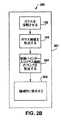
図2A〜図2Cは、ウェブ521(図5参照)が乾燥又は非水性バインダーを用いて形成されている(260)点を除き図1A〜図1Cの実施形態とほぼ同じ方法の例示の実施形態を示している。図2Aの方法200は、全体として、図1Aの方法100に対応している。図2Bの方法250は、全体として、図1Bの方法150に対応している。図2Cの方法270は、全体として、図1Cの方法170に対応している。 2A-2C are exemplary embodiments of the same method as the embodiment of FIGS. 1A-1C, except that the web 521 (see FIG. 5) is formed (260) using a dry or non-aqueous binder. Is shown. The
図2Dは、図2Cの方法270に類似した方法290を示している。図2Dでは、破線のボックスに入れて示されたステップは、オプションである。図2Dに示された例示の実施形態では、ウェブを形成する前ではなく(これに加えて)乾燥バインダーをオプションとして、ステップ292でウェブに添加すると共に/或いはステップ294で層状ウェブに添加することができる。例えば、ステップ292が設けられる場合、ウェブを乾燥バインダーなしで形成し、次に、層状化前且つ/或いは層状化中、乾燥バインダーをウェブに添加するのが良い。ステップ294が設けられる場合、ウェブを乾燥バインダーなしで形成して層状化するのが良く、次に乾燥バインダーを層状ウェブに添加する。 FIG. 2D shows a
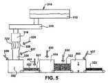
図5を参照すると、乾燥バインダー(大きな矢印で示されている)をプロセス中、様々な互いに異なる箇所で繊維322及び/又はウェブ521に添加するのが良い。矢印525は、乾燥バインダーを収集部材のところ又はこの上で繊維322に添加するのが良いことを示している。矢印527は、乾燥バインダーをダクト330中の繊維322に添加するのが良いことを示している。矢印529は、乾燥バインダーを形成装置332内で繊維322に添加するのが良いことを示している。矢印531は、乾燥バインダーをウェブが形成装置332を出た後にウェブ321に添加するのが良いことを示している。矢印533は、乾燥バインダーをウェブが層状化装置334によって層状にされているときにウェブ321に添加するのが良いことを示している。矢印535は、ウェブを層状にした後に乾燥バインダーをウェブ321に添加するのが良いことを示している。矢印537は、乾燥バインダーをオーブン550内でウェブ321又は層状ウェブに添加するのが良いことを示している。乾燥バインダーを繊維322又はウェブ321に添加して何らかの仕方で乾燥バインダーを含むウェブ521を形成するのが良い。 Referring to FIG. 5, dry binder (shown by large arrows) may be added to the
例示の一実施形態では、乾燥バインダーを繊維化装置318から見て下流側の相当な距離のところに位置する場所で繊維322に塗布する。例えば、乾燥バインダーを繊維の温度及び/又は繊維の周りの空気の温度が繊維化装置のところの繊維の温度及び周りの空気の温度よりも著しく低い場所で繊維に塗布するのが良い。例示の一実施形態では、乾燥バインダーを繊維の温度及び/又は繊維の周りの空気の温度が乾燥バインダーが溶融する温度又は乾燥バインダーが完全に硬化し又は反応する温度よりも低い場所で塗布する。例えば、熱可塑性バインダーを繊維322の温度及び/又はこれら繊維の周りの空気の温度が熱可塑性バインダーの融点よりも低い製造ライン中の箇所で塗布するのが良い。熱硬化性バインダーを繊維322の温度及び/又はこれら繊維の周りの空気の温度が熱硬化性バインダーの硬化温度よりも低い製造ライン中の箇所で塗布するのが良い。すなわち、熱硬化性バインダーを繊維322の温度及び/又はこれら繊維の周りの空気の温度が、熱可塑性バインダーが完全に反応し又は熱硬化性バインダーの完全な架橋が起こる温度よりも低い箇所で塗布するのが良い。例示の一実施形態では、乾燥バインダーを繊維322の温度及び/又はこれら繊維の周りの空気の温度が250°F(121.1℃)未満である製造ライン中の場所で塗布する。例示の一実施形態では、図5の矢印527,529,531,533,535によって示されている場所のところでの繊維の温度及び/又はこれら繊維の周りの空気の温度は、乾燥バインダーが溶融し又は完全に硬化する温度よりも低い。 In one exemplary embodiment, the dry binder is applied to the
例示の一実施形態では、バインダーアプリケータは、乾燥粉末用に構成された噴霧器である。噴霧器は、スプレーの力が調節可能であるように構成されているのが良く、それにより繊維材料の連続ウェブ中への乾燥粉末の幾分かの入り込みが可能である。変形例として、バインダーアプリケータは、例えば、乾燥バインダーをガラス繊維の連続ウェブ320中に引き込むのに十分な他の構造体、機構体若しくは装置又はこれらの組み合わせ、例えば、真空装置であっても良い。 In one exemplary embodiment, the binder applicator is a nebulizer configured for dry powder. The atomizer may be configured so that the spray force is adjustable, thereby allowing some penetration of the dry powder into the continuous web of fibrous material. Alternatively, the binder applicator may be, for example, other structures, mechanisms or devices or combinations thereof sufficient to draw the dry binder into the
オプションとしての乾燥バインダーは、多種多様な形態を取ることができる。ウェブ521を形成するよう繊維322を互いに保持する非水性媒体を用いることができる。例示の一実施形態では、乾燥バインダーは、当初、繊維に塗布されている間、実質的に100%の固形分で構成される。本明細書で用いられる「実質的に100%固形分」という表現は、バインダーの重量を基準として約2パーセント以下、好ましくは約1パーセント以下の量の希釈剤、例えば水を含む結合剤を意味する(バインダーが乾燥し又は硬化した後ではなく、バインダーが塗布されているとき)。しかしながら、理解されるべきこととして、或る特定の実施形態では、バインダーが、特定の用途及び設計上の要件に応じて所望の量の希釈剤、例えば水を含んでも良い。例示の一実施形態では、乾燥バインダーは、液体の形態では塗布されず、更に水を主成分としない熱可塑性樹脂を主成分とする材料である。他の実施形態では、乾燥バインダーは、他の物質又は物質の他の組み合わせであって良く、かかる物質としては、非限定的な例として、ポリマー熱硬化性樹脂が挙げられる。乾燥バインダーは、任意の形態又は形態の任意の組み合わせを有することができ、かかる形態としては、非限定的な例として、粉末、粒子、繊維及び/又はホットメルトが挙げられる。ホットメルトポリマーの例としては、エチレン‐ビニルアセテートコポリマー、エチレン‐アクリレートコポリマー、低密度ポリエチレン、高密度ポリエチレン、アタクチクポリプロピレン、ポリブタジエン‐1、スチレンブロックコポリマー、ポリアミド、熱可塑性ポリウレタン、スチレンブロックコポリマー、ポリエステル等が挙げられるが、これらには限定されない。例示の一実施形態では、硬化繊維状パックを包装、貯蔵及び輸送のために圧縮するのが良いが、設置時にその厚さを取り戻す(「ロフト回復」と呼ばれるプロセス)よう十分な乾燥バインダーを塗布する。 The optional dry binder can take a wide variety of forms. A non-aqueous medium that holds the
図2A〜図2D及び図5に示された実施例では、ガラス繊維322をオプションとして乾燥バインダーがガラス繊維に塗布される前又は後に潤滑剤で被覆し又は部分的に被覆するのが良い。例示の実施形態では、潤滑剤を乾燥バインダー後に塗布してガラス繊維322に対する乾燥バインダーの接着性を向上させる。潤滑剤は、上述した潤滑剤のうちの任意のものであって良い。 In the embodiment shown in FIGS. 2A-2D and FIG. 5,
図5を参照すると、未反応乾燥バインダー521を含む連続ウェブを形成装置332からオプションとしての層状化機構体334に移送する。層状化機構体は、多種多様な形態を取ることができる。例えば、層状化機構体は、ウェブ321を縦方向D1に層状にする重ね機構体であっても良く、ウェブを縦方向と実質的に直交した方向に重ねる交差重ね機構体であっても良い。バインダーレスウェブ321を層状にする上述した交差重ね装置を用いると、未反応乾燥バインダーを含むウェブ521を層状にすることができる。 Referring to FIG. 5, a continuous web containing unreacted
例示の実施形態では、連続ウェブ521の乾燥バインダーは、硬化オーブン550内で熱的に硬化されるよう構成されている。例示の実施形態では、硬化オーブン550は、絡ませ機構体345に取って代わっている。というのは、乾燥バインダーは、繊維322を互いに保持するからである。別の例示の実施形態では、硬化オーブン550と絡ませ機構体345の両方が設けられる。 In the illustrated embodiment, the dry binder of
図6及び図7は、全体が符号610で示されている繊維材料からパックを形成する方法の別の例示の実施形態を概略的に示している。図6を参照すると、溶融ガラス612を溶融室614からフォアハース616に供給する。溶融ガラス612を所望の化学組成物を与えるような比率で組み合わされた種々の原料で作られるのが良い。溶融ガラス612は、フォアハース616から複数個の回転繊維化装置618に流れる。 6 and 7 schematically illustrate another exemplary embodiment of a method of forming a pack from a fibrous material generally designated 610. Referring to FIG. 6,
図6を参照すると、回転繊維化装置618は、溶融ガラス612を受け入れ、その後、高温ガスの流れ中に同伴されたガラス繊維622のベール620を形成する。以下に詳細に説明するように、回転繊維化装置618により形成されたガラス繊維622は、長く且つ細い。したがって、長く且つ細いガラス繊維622を形成するのに十分な任意所望の繊維化装置(回転式又はその他の形式)を利用することができる。図6及び図7に示されている実施形態は、所与の数の、例えば2つの回転繊維化装置618を示しているが、理解されるべきこととして、任意所望の数の回転繊維化装置618を用いることができる。 Referring to FIG. 6, a
高温ガスの流れをオプションとしての吹き込み機構体、例えば非限定的な例として、環状ブロワ(図示せず)又は環状バーナ(図示せず)によって作ることができる。一般に、吹き込み機構体は、ガラス繊維622のベール620を所与の方向に、通常下向きに差し向けるよう構成されている。理解されるべきこととして、高温ガスの流れを任意所望の構造体、機構体若しくは装置又はこれらの任意の組み合わせによって作ることができる。 The hot gas flow can be produced by an optional blowing mechanism, such as, by way of non-limiting example, an annular blower (not shown) or an annular burner (not shown). Generally, the blowing mechanism is configured to direct the
図6に示されているように、オプションとしての吹き付け機構体626が回転繊維化装置618の下に配置されるのが良く、かかる吹き付け機構体は、水又は他の流体の微細な液滴をベール620中の高温ガスに吹き付けて高温ガスの流れの冷却を助けて繊維622を接触による損傷から保護すると共に/或いは繊維622の結合性能を高めるよう構成されている。吹き付け機構体626は、微細な水滴をベール620中の高温ガスに吹き付けて高温ガスの流れの冷却を助けて繊維622を接触による損傷から保護すると共に/或いは繊維622の結合性能を高めるのに十分な任意所望の構造体、機構体又は装置であって良い。図6に示された実施形態は、吹き付け機構体626の使用を示しているが、理解されるべきこととして、吹き付け機構体626の使用は、オプションであり、パック繊維材料610から形成する方法を吹き付け機構体626の使用なしで実施することができる。 As shown in FIG. 6, an
オプションとして、ガラス繊維622をガラス繊維が形成された後に潤滑剤で被覆するのが良い。図示の実施形態では、複数個のノズル628が回転繊維化装置618よりも下の位置でベール620周りに配置されるのが良い。ノズル628は、潤滑剤(図示せず)を潤滑剤源(図示せず)からガラス繊維622に供給するよう構成されているのが良い。 Optionally, the glass fibers 622 may be coated with a lubricant after the glass fibers are formed. In the illustrated embodiment, a plurality of nozzles 628 may be disposed around the
潤滑剤の塗布は、任意所望の構造体、機構体又は装置、例えば非限定的な例として弁(図示せず)によって正確に制御することができる。或る特定の実施形態では、潤滑剤は、シリコーン化合物、例えばシロキサン、ジメチルシロキサン及び/又はシランであるのが良い。潤滑剤は、他の物質又は物質の組み合わせ、例えば油又は油乳濁液であっても良い。油又は油乳濁液は、鉱物油又は鉱物油乳濁液及び/又は野菜油又は野菜油乳濁液であっても良い。例示の実施形態では、潤滑剤は、結果として得られる繊維状材料のパックの重量を基準として約1.0パーセント油及び/又はシリコーン化合物の量で塗布される。しかしながら、他の実施形態では、潤滑剤の量は、約1.0重量パーセントよりも多い又は少ない油及び/又はシリコーン化合物であって良い。 The application of lubricant can be accurately controlled by any desired structure, mechanism or device, such as a valve (not shown) as a non-limiting example. In certain embodiments, the lubricant may be a silicone compound, such as siloxane, dimethylsiloxane and / or silane. The lubricant may be another substance or combination of substances such as oil or oil emulsion. The oil or oil emulsion may be mineral oil or mineral oil emulsion and / or vegetable oil or vegetable oil emulsion. In an exemplary embodiment, the lubricant is applied in an amount of about 1.0 percent oil and / or silicone compound, based on the weight of the resulting fibrous material pack. However, in other embodiments, the amount of lubricant may be greater than or less than about 1.0 weight percent oil and / or silicone compound.
図6に示されている実施形態は、潤滑剤(図示せず)をガラス繊維622に供給するためのノズル628の使用を示しているが、理解されるべきこととして、ノズル628の使用は、オプションであり、パックを繊維材料610から形成する方法をノズル628の使用なしで実施することができる。 Although the embodiment shown in FIG. 6 illustrates the use of nozzle 628 to supply lubricant (not shown) to glass fiber 622, it should be understood that the use of nozzle 628 includes Optionally, the method of forming the pack from the
図示の実施形態では、高温ガスの流れ中に同伴されたガラス繊維622をオプションとしての収集部材624によって収集するのが良い。収集部材624は、ガラス繊維622及び高温ガスの流れを容易に受け入れるような寸法形状のものである。収集部材624は、ガラス繊維622及び高温ガスの流れを下流側の処理ステーション、例えば形成装置632a,632bに移送するためにダクト630にそらすよう構成されている。他の実施形態では、ガラス繊維622を運搬機構体(図示せず)上に収集して例えばブランケット又はバット(図示せず)を形成することができる。バットを運搬機構体によって次の処理ステーション(図示せず)に運搬することができる。収集部材624及びダクト630は、ガラス繊維622及び高温ガスの流れを受け入れて運搬するのに適した全体として中空の形態を備えた任意の構造体であって良い。図6に示されている実施形態は、収集部材624の使用を示しているが、理解されるべきこととして、ガラス繊維622及び高温ガスの流れをダクト630にそらすための収集部材624の使用は、オプションであり、パックを繊維材料610から形成する方法を収集部材624の使用なしで実施することができる。 In the illustrated embodiment, glass fibers 622 entrained in the hot gas stream may be collected by an optional collection member 624. The collection member 624 is sized and shaped to readily accept the flow of glass fibers 622 and hot gas. The collection member 624 is configured to divert the glass fiber 622 and hot gas flow to the
図6及び図7に示されている実施形態では、単一の繊維化装置618が個々のダクト630と関連しており、その結果、単一の繊維化装置618からのガラス繊維622及び高温ガスの流れがダクト630に入るガラス繊維622及び高温ガスの流れの唯一の源である。変形例として、個々のダクト630が多数の繊維化装置618(図示せず)からガラス繊維622及び高温ガスの流れを受け取るよう構成されていても良い。 In the embodiment shown in FIGS. 6 and 7, a
再び図6を参照すると、オプションとして、ヘッダシステム(図示せず)が形成装置632a,632bと繊維化装置618との間に配置されるのが良い。ヘッダシステムは、複数個の繊維化装置618から流れ出たガラス繊維622及びガスを組み合わせる一方で結果として得られた組み合わせ流の特性を制御することができるチャンバとして構成されるのが良い。或る特定の実施形態では、ヘッダシステムは、繊維化装置618からのガラス繊維622とガスの流れを組み合わせるよう構成され、更に、結果として得られた組み合わせ流を形成装置632a,632bに差し向けるよう構成された制御システム(図示せず)を含むのが良い。かかるヘッダシステムは、或る特定の繊維化装置618の保守及びクリーニングを残りの繊維化装置618の作動停止の必要なく可能にすることができる。オプションとして、ヘッダシステムは、ガラス繊維622及びガスの流れを制御すると共に差し向ける任意所望の手段を含むのが良い。 Referring again to FIG. 6, as an option, a header system (not shown) may be placed between the forming
次に図7を参照すると、同伴ガラス繊維622を含むガスの流れの運動量により、ガラス繊維622は、引き続きダクト630を通って形成装置632a,632bに流れる。形成装置632a,632bは、幾つかの機能を実行するよう構成されているのが良い。第1に、形成装置632a,632bは、同伴ガラス繊維622をガスの流れから分離するよう構成されているのが良い。第2に、形成装置632a,632bは、所望の厚さを有する繊維材料の連続して薄く且つ乾燥状態のウェブを形成するよう構成されているのが良い。第3に、形成装置632a,632bは、ガラス繊維622を「ランダム性」の任意所望の度合いでウェブ内で配向させることができる仕方でガラス繊維622をガスの流れから分離することができるよう構成されているのが良い。本明細書に用いられる「ランダム性」という用語は、ガラス繊維622又はガラス繊維622の部分をX、Y又はZ寸法のうちの任意のものに非優先的に配向させることができることを意味するものと定められる。或る特定の場合、高いランダム性度を有することが望ましい場合がある。他の場合、繊維622が非ランダム的に配向され、換言すると、繊維622が実質的に互いに同一平面内に位置し又は実質的に互いに平行であるよう繊維622のランダム性を制御することが望ましい場合がある。第4に、形成装置632a,632bは、繊維材料の連続ウェブを他の下流側の操作に移送するよう構成されているのが良い。 Referring now to FIG. 7, due to the momentum of the gas flow including the entrained glass fibers 622, the glass fibers 622 continue to flow through the
図7に示されている実施形態では、形成装置632a,632bは、回転可能に構成されたドラム(図示せず)を有する。このドラムは、任意所望の量のフォルアミナス(foraminous)表面及び高圧又は低圧の領域を有するのが良い。変形例として、形成装置632a,632bの各々は、同伴ガラス繊維622をガスの流れから分離し、所望の厚さを有する繊維材料の連続ウェブを形成し、そしてこの繊維材料の連続ウェブを他の下流側の操作に移送するのに十分な他の構造体、機構体及び装置で形成されても良い。図7に示されている例示の実施形態では、形成装置632a,632bの各々は、互いに同一である。しかしながら、他の実施形態では、形成装置632a,632bの各々は、互いに異なっていても良い。 In the embodiment shown in FIG. 7, the forming
再び図7を参照すると、繊維材料の連続ウェブを形成装置632a,632bからオプションとしてのバインダーアプリケータ646に移送する。バインダーアプリケータ646は、「乾燥バインダー」を繊維材料の連続ウェブに塗布するよう構成されている。「乾燥バインダー」という用語は、バインダーが繊維に塗布されている間、実質的に100%の固形分で構成される。本明細書で用いられる「実質的に100%固形分」という表現は、バインダーの重量を基準として約2パーセント以下、好ましくは約1パーセント以下の量の希釈剤、例えば水を含む結合剤を意味する(バインダーが乾燥し又は硬化した後ではなく、バインダーが塗布されているとき)。しかしながら、理解されるべきこととして、或る特定の実施形態では、バインダーが特定の用途及び設計上の要件に応じて所望の任意の量の希釈剤、例えば水を含んでも良い。バインダーは、硬化オーブン650内で熱的に硬化するよう構成されているのが良い。本明細書において、「硬化する」及び「熱的に硬化する」という用語は、乾燥バインダーがウェブの繊維を互いに結合するようにする化学反応及び/又は1回又は2回以上の相変化を意味している。例えば、熱硬化性の乾燥バインダー(又は乾燥バインダーの熱硬化性成分)は、熱を加えた結果として生じる化学反応の結果として硬化し又は熱的に硬化する。熱可塑性乾燥バインダー(又は乾燥バインダーの熱可塑性成分)は、軟化又は溶融相への加熱、そして次に固体相への冷却の結果として、固まり又は熱的に硬化する。 Referring again to FIG. 7, a continuous web of fibrous material is transferred from the forming
例示の一実施形態では、乾燥バインダーは、液体の形態では塗布されず、更に水を主成分としない熱可塑性樹脂を主成分とする材料である。他の実施形態では、乾燥バインダーは、他の物質又は物質の他の組み合わせであって良く、かかる物質としては、非限定的な例として、ポリマー熱硬化性樹脂が挙げられる。乾燥バインダーは、任意の形態又は形態の任意の組み合わせを有することができ、かかる形態としては、非限定的な例として、粉末、粒子、繊維及び/又はホットメルトが挙げられる。ホットメルトポリマーの例としては、エチレン‐ビニルアセテートコポリマー、エチレン‐アクリレートコポリマー、低密度ポリエチレン、高密度ポリエチレン、アタクチクポリプロピレン、ポリブタジエン‐1、スチレンブロックコポリマー、ポリアミド、熱可塑性ポリウレタン、スチレンブロックコポリマー、ポリエステル等が挙げられるが、これらには限定されない。硬化済み繊維状パックを包装、貯蔵及び輸送のために圧縮するのが良いが、設置時にその厚さを取り戻す(「ロフト回復」と呼ばれるプロセス)よう十分な乾燥バインダーを塗布する。乾燥バインダーを繊維材料の連続ウェブに塗布すると、オプションとして未反応バインダーを含む連続ウェブが形成される。 In one exemplary embodiment, the dry binder is a material based on a thermoplastic resin that is not applied in liquid form and that is not water based. In other embodiments, the dry binder may be other materials or other combinations of materials, such materials include, but are not limited to, polymeric thermosetting resins. The dry binder can have any form or any combination of forms, such forms include, but are not limited to, powders, particles, fibers and / or hot melts. Examples of hot melt polymers include ethylene-vinyl acetate copolymer, ethylene-acrylate copolymer, low density polyethylene, high density polyethylene, atactic polypropylene, polybutadiene-1, styrene block copolymer, polyamide, thermoplastic polyurethane, styrene block copolymer, polyester However, it is not limited to these. The cured fibrous pack may be compressed for packaging, storage and transportation, but sufficient dry binder is applied to restore its thickness upon installation (a process called “loft recovery”). Applying the dried binder to a continuous web of fiber material optionally forms a continuous web containing unreacted binder.
図6及び図7に示されている実施形態では、バインダーアプリケータ646は、乾燥粉末向きに構成された噴霧器である。噴霧器は、スプレーの力が調節可能であるように構成されているのが良く、それにより繊維材料の連続ウェブ中への乾燥粉末の幾分かの入り込みが可能である。変形例として、バインダーアプリケータ646は、例えば、「乾燥バインダー」をガラス繊維の連続ウェブ中に引き込むのに十分な他の構造体、機構体若しくは装置又はこれらの組み合わせ、例えば、真空装置であっても良い。 In the embodiment shown in FIGS. 6 and 7, the
図7に示されている実施形態は、乾燥バイダーを繊維材料の連続ウェブに塗布するよう構成されたバインダーアプリケータ646を示しているが、或る特定の実施形態では、繊維材料の連続ウェブにバインダーを塗布しないことは、本発明の範囲に含まれる。 Although the embodiment shown in FIG. 7 shows a
再び図7を参照すると、オプションとして未反応バインダーを含む連続ウェブをバインダーアプリケータ646から対応の交差重ね機構体634a,634bに移送する。図7に示されているように、形成装置632aは、交差重ね機構体634aと関連し、形成装置632bは、交差重ね機構体634bと関連している。交差重ね機構体634a,634bは、第1のコンベヤ636と連係して機能する。第1のコンベヤ636は、矢印D1で示されている縦方向に動くよう構成されている。交差重ね機構体634aは、オプションとして未反応バインダーを含む連続ウェブをオプションとしてのバインダーアプリケータ646から受け入れるよう構成されると共に更にオプションとして未反応バインダーを含む連続ウェブの交互の層を第1のコンベヤ636が縦方向に動いているときに第1のコンベヤ636上に堆積させるよう構成され、それにより、繊維本体の初期層が形成される。堆積プロセスでは、交差重ね機構体634aは、矢印D2で示されているように横方向に交互の層を形成する。したがって、オプションとして未反応バインダーを含む堆積状態の連続ウェブが交差重ね機構体634aから縦方向D1に動いているとき、追加の層が下流側交差重ね機構体634bによって繊維本体上に堆積される。交差重ね機構体634a,634bによって堆積された繊維本体の結果として生じる層は、パックを形成する。 Referring again to FIG. 7, a continuous web optionally containing unreacted binder is transferred from the
図示の実施形態では、交差重ね機構体634a,634bは、未反応バインダーを含む連続ウェブの運動を正確に制御して未反応バインダーを含む連続ウェブを第1のコンベヤ636上に堆積させるよう構成された装置であり、その結果、オプションとして未反応バインダーを含む連続ウェブが損傷を受けないようになる。交差重ね機構体634a,634bは、任意所望の構造体を含むことができ、これら交差重ね機構体は、任意所望の仕方で作動するよう構成されるのが良い。一実施例では、交差重ね機構体634a,634bは、横方向D2に前後に動くよう構成されたヘッド(図示せず)を有するのが良い。この実施形態では、可動ヘッドの速度は、横方向における前後のヘッドの運動が実質的に同一であり、それにより繊維本体の結果として生じる層の一様性が得られるよう協調される。別の実施例では、第1のコンベヤ636の中心線上に心出しされるよう構成された垂直コンベヤ(図示せず)を利用するのが良い。垂直コンベヤは、更に、第1のコンベヤ636の上方に設けられたピボット機構体から揺動して例えばオプションとして未反応バインダーを含む連続ウェブを第1のコンベヤ636上に堆積させるよう構成されている。交差重ね機構体の幾つかの例を上述したが、理解されるべきこととして、交差重ね機構体634a,634bは、他の構造体、機構体若しくは装置又はこれらの組み合わせであって良い。 In the illustrated embodiment, the
再び図7を参照すると、オプションとして、第1のコンベヤ636上へのオプションとして未反応バインダーを含む連続ウェブの位置決めは、例えばパックの一様性を向上させるようコントローラ(図示せず)によって達成されるのが良い。コントローラは、任意所望の構造体、機構体若しくは装置又はこれらの組み合わせであって良い。 Referring again to FIG. 7, the positioning of the continuous web, optionally including unreacted binder, on the
層状ウェブ又はパックは、任意所望の厚さを有することができる。パックの厚さは、幾つかの変数の関数である。第1に、パックの厚さは、形成装置632a,632bの各々によって形成されるオプションとして未反応バインダーを含む連続ウェブの厚さの関数である。第2に、パックの厚さは、交差重ね機構体634a,634bがオプションとして未反応バインダーを含む連続ウェブの層を第1のコンベヤ636上に堆積させる速度の関数である。第3に、パックの厚さは、第1のコンベヤ636の速度の関数である。例示の実施形態では、パックは、約0.1インチ(0.25cm)から約20.0インチ(50.80cm)までの範囲の厚さを有するのが良い。他の実施形態では、パックは、約0.1インチ(0.25cm)以下又は約20.0インチ(50.80cm)以上の厚さを有しても良い。 The layered web or pack can have any desired thickness. The pack thickness is a function of several variables. First, the pack thickness is a function of the thickness of the continuous web that optionally includes unreacted binder formed by each of the forming
上述したように、交差重ね機構体634a,634bは、第1のコンベヤ636が縦方向D1に動いているときにオプションとして未反応バインダーを含む連続ウェブの交互の層を第1のコンベヤ636上に堆積させるよう構成され、それにより、繊維本体の層が形成される。図示の実施形態では、交差重ね機構体634a,634b及び第1のコンベヤ636は、例えば約1個から約60個の範囲の量の層を有する繊維本体を形成するよう協調される。他の実施形態では、交差重ね機構体634a,634b及び第1のコンベヤ636は、例えば60個の層を超える繊維本体を含む任意所望の量の層を有する繊維本体を形成するよう協調させられるのが良い。 As described above, the
オプションとして、交差重ね機構体634a,634bは、調節可能であるのが良く、それにより、交差重ね機構体634a,634bは、任意所望の幅を有するパックを形成することができる。或る特定の実施形態では、パックは、約98.0インチ(248.92cm)から約236.0インチ(599.44cm)までの範囲の全体幅を有するのが良い。変形例として、パックは、約98.0インチ(248.92cm)以下又は約236.0インチ(599.44cm)以上の全体幅を有しても良い。 Optionally, the cross-over features 634a, 634b can be adjustable, so that the cross-over features 634a, 634b can form packs having any desired width. In certain embodiments, the pack may have an overall width ranging from about 98.0 inches (248.92 cm) to about 236.0 inches (599.44 cm). Alternatively, the pack may have an overall width of about 98.0 inches (248.92 cm) or less, or about 236.0 inches (599.44 cm) or more.
交差重ね機構体634a,634bを繊維本体の形成の際に共同して関与するものとして上述したが、理解されるべきこととして、他の実施形態では、交差重ね機構体634a,634bは、例えば繊維本体の別々のレーンを形成するよう互いに別個独立に作動しても良い。 Although the cross-over features 634a, 634b have been described above as jointly involved in forming the fiber body, it should be understood that in other embodiments, the cross-over features 634a, 634b may be, for example, fibers It may operate independently of each other to form separate lanes of the body.
図6及び図7を参照すると、交差重ね機構体634a,634bによって形成された層を有するパックを第1のコンベヤ636によってオプションとしてのトリム機構体640に運ぶ。オプションとしてのトリム機構体640は、例えばパックの所望の幅を形成するようパックの縁部をトリムするよう構成されている。例示の実施形態では、パックは、約98.0インチ(248.92cm)から約236.0インチ(599.44cm)までの範囲のトリム後幅を有するのが良い。変形例として、パックは、約98.0インチ(248.92cm)未満又は約236.0インチ(599.44cm)を超えるトリム後幅を有しても良い。 Referring to FIGS. 6 and 7, a pack having a layer formed by
図示の実施形態では、オプションとしてのトリム機構体640は、パックの各側に配置された複数個の回転ソー(図示せず)を備えたソーシステムを含む。変形例として、トリム機構体640は、非限定的な例として水ジェット、圧縮ナイフを含む他の構造体、機構体若しくは装置又はこれらの組み合わせであっても良い。 In the illustrated embodiment,
図示の実施形態では、トリム機構体640は、有利には、硬化オーブン650から見て上流側に配置される。トリム機構体640を硬化オーブン650から見て上流側に配置することにより、パックをこれが硬化オーブン650内で熱的に硬化される前にトリムすることができる。オプションとして、トリム機構体640によってパックからトリムされた材料をダクト630中のガスの流れ及びガラス繊維に戻して形成装置632a,632b内で再利用するのが良い。トリム材料の再利用により、有利には、トリム材料の処分と関連した潜在的な環境上の問題の発生が防止される。図6に示されているように、管路642がトリム機構体640をダクト630に連結し、この管路は、形成装置632a,632bへのトリム材料の戻りを容易にするよう構成されている。図6及び図7に示されている実施形態は、トリム材料の再利用を示しているが、理解されるべきこととして、トリム材料の再利用は、オプションであり、パックを繊維材料610から形成する方法は、トリム材料の再利用なしで実施できる。別の例示の実施形態では、トリム機構体640は、硬化オーブン650から見て下流側に配置される。この位置決めは、トリム材料が再利用されない場合に特に有用である。パックをトリムすることにより、トリム済みパックが形成される。 In the illustrated embodiment, the
トリム済みパックを第1のコンベヤ636によって第2のコンベヤ644に運搬する。図6に示されているように、第2のコンベヤ644は、第1のコンベヤ636から「ステップダウン」されるよう配置されるのが良い。本明細書で用いられる「ステップダウンされ」という用語は、第2のコンベヤ644の上面が第1のコンベヤ636の上面よりも垂直方向下に位置するよう配置されることを意味するものとする。コンベヤのステップダウンの仕方について以下に詳細に説明する。 The trimmed pack is conveyed by the
再び図6及び図7を参照すると、トリム済みパックを第2のコンベヤ644によってオプションとしての絡ませ機構体645に運搬する。絡ませ機構体645は、トリム済みパックの層を形成する個々の繊維622を互いに絡ませるよう構成されている。パック内のガラス繊維622を互いに絡ませることにより、パックが結束される。乾燥バインダーが含まれる実施形態では、ガラス繊維622を互いに絡ませることにより、有利には、機械的性質、例えば引張り強度及び剪断強度を向上させることができる。図示の実施形態では、絡ませ機構体645は、ニードリング機構体である。他の実施形態では、絡ませ機構体645は、非限定的な例として縫合機構体を含む他の構造体、機構体若しくは装置又はこれらの組み合わせを有しても良い。図6及び図7に示されている実施形態は、絡ませ機構体645の使用を示しているが、理解されるべきこととして、絡ませ機構体645の使用は、オプションであり、パックを繊維材料610から形成する方法を絡ませ機構体645の使用なしで実施することができる。パック内の繊維を互いに絡ませることにより、絡み合いパックが形成される。 Referring again to FIGS. 6 and 7, the trimmed pack is transported by the
第2のコンベヤ644は、オプションとしての乾燥バインダー入りの、オプションとしてトリムされると共に/或いはオプションとして絡み合ったパック(以下、トリム済みパックと絡み合いパックの両方を、単に「パック」と言う)を第3のコンベヤ648に運搬する。パックが乾燥バインダーを含む場合、第3のコンベヤ648は、このパックをオプションとしての硬化オーブン650に運搬するよう構成されている。硬化オーブン650は、流体、例えば加熱空気をパック中に吹き込んで乾燥バインダーを硬化させると共にガラス繊維622を全体としてランダムな三次元構造の状態にしっかりと結合するよう構成されている。パックを硬化オーブン650内で硬化させることにより、硬化済みパックが形成される。 The
上述したように、パックは、オプションとして、乾燥バインダーを含む。伝統的な液状バインダーではなく、乾燥バインダーの使用により、有利には、硬化オーブン650が乾燥バインダーをパック内で硬化させるのに少ないエネルギーを用いることができる。図示の実施形態では、硬化オーブン650内での乾燥バインダーの使用の結果として、従来型硬化オーブンにより液状又は水性バインダーに用いられるエネルギーと比較して約30.0%から約80.0%までの範囲のエネルギーの節約が得られる。さらに別の実施形態では、エネルギー節約は、80.0%を超える場合がある。硬化オーブン650は、任意所望の硬化構造体、機構体若しくは装置又はこれらの組み合わせであって良い。 As described above, the pack optionally includes a dry binder. The use of a dry binder rather than a traditional liquid binder advantageously allows the curing
第3のコンベヤ648は、硬化済みパックを第4のコンベヤ652に運搬する。第4のコンベヤ652は、硬化済みパックを切断機構体654に運搬するよう構成されている。オプションとして、切断機構体654は、数個の切断モード向きに構成されているのが良い。第1のオプションとしての切断モードでは、切断機構体は、硬化済みパックを縦方向D1に沿って垂直方向に切断してレーンを形成するよう構成されている。形成されたレーンは、任意所望の幅を有することができる。第2のオプションとしての切断モードでは、切断機構体は、硬化済みパックを水平方向に2等分して厚さを有する連続パックを形成するよう構成されている。結果として得られる2等分されたパックは、任意所望の厚さを有することができる。硬化済みパックを切断することにより、切断済みパックが形成される。 Third conveyor 648 conveys the cured pack to
図示の実施形態では、切断機構体654は、ソー及びナイフのシステムを含む。変形例として、切断機構体654は、他の構造体、機構体若しくは装置又はこれらの組み合わせであって良い。再び図6及び図7を参照すると、切断機構体654は、有利には、切断作業中に形成されるダスト及び他の屑材料の捕捉を可能にするよう配置される。オプションとして、切断機構体に由来するダスト及び他の屑材料をダクト630中のガスの流れ及びガラス繊維に戻して形成装置632a,632b内で再利用するのが良い。ダスト及び屑材料の再利用により、有利には、ダスト及び屑材料の処分と関連した潜在的な環境上の問題の発生が防止される。図6及び図7に示されているように、管路655が切断機構体654をダクト630に連結し、この管路は、形成装置632a,632bへのダスト及び屑材料の戻りを容易にするよう構成されている。図6及び図7に示されている実施形態は、ダスト及び屑材料の再利用を示しているが、理解されるべきこととして、ダスト及び屑材料の再利用は、オプションであり、パックを繊維材料610から形成する方法は、ダスト及び屑材料の再利用なしで実施できる。 In the illustrated embodiment, the
オプションとして、切断機構体654への硬化済みパックの運搬に先立って、硬化済みパックの主要(major )表面を図6に示されているような表面仕上げ機構体662a,662bによって1つ又は複数の表面仕上げ材料で表面仕上げするのが良い。図示の実施形態では、硬化済みパックの主要な上面は、表面仕上げ機構体662aによって提供される表面仕上げ材料663aで表面仕上げされ、硬化済みパックの主要な下面は、表面仕上げ機構体662bにより提供される表面仕上げ材料663bで表面仕上げされる。表面仕上げ材料は、任意所望の材料であって良く、かかる材料としては、紙、ポリマー材料又は不織ウェブが挙げられる。表面仕上げ機構体662a,662bは、任意所望の構造体、機構体若しくは装置又はこれらの組み合わせであって良い。図示の実施形態では、表面仕上げ材料663a,663bを硬化済みパック(パックがバインダーを含む場合)に接着剤で貼り付ける。他の実施形態では、表面仕上げ材料663a,663bを他の方法で硬化済みパックに貼り付けても良く、かかる方法としては、非限定的な例として、音波溶接が挙げられる。図6に示されている実施形態は、硬化済みパックの主要な表面への表面仕上げ材料663a,663bの貼り付けを示しているが、理解されるべきこととして、硬化済みパックの主要表面への表面仕上げ材料663a,663bの貼り付けは、オプションであり、パックを繊維材料610から形成する方法は、硬化済みパックの主要表面への表面仕上げ材料663a,663bの貼り付けなしで実施できる。 Optionally, prior to transporting the cured pack to the
図6及び図7を参照すると、第4のコンベヤ652は、切断済みパックをオプションとしての細断機構体656に運搬する。細断機構体656は、切断済みパックを縦方向D1を横切って所望の長さに切断するよう構成されている。図示の実施形態では、細断機構体656は、切断済みパックが縦方向D1に連続的に動いているときに切断済みパックを切断するよう構成されている。変形例として、細断機構体656は、バッチ式細断作業向きに構成されているのが良い。切断済みパックを所定の長さに切断することにより、寸法決めパックが形成される。細断済みパックの長さは、任意所望の寸法を有することができる。 With reference to FIGS. 6 and 7, the
細断機構体は、当該技術分野においては知られており、これにつき本明細書において説明することはしない。細断機構体656は、任意所望の構造体、機構体若しくは装置又はこれらの組み合わせであって良い。 Shredding mechanisms are known in the art and will not be described herein. The
オプションとして、細断機構体656への切断済みパックの運搬に先立って、切断済みパックの非主要(minor )表面を図7に示されているように縁取り機構体666a,666bによって1つ又は複数の縁取り材料で表面仕上げするのが良い。縁取り材料は、任意所望の材料であって良く、かかる材料としては、紙、ポリマー材料又は不織ウェブが挙げられる。縁取り機構体666a,666bは、任意所望の構造体、機構体若しくは装置又はこれらの組み合わせであって良い。図示の実施形態では、縁取り材料667a,667bを切断済みパックに接着剤で貼り付ける。他の実施形態では、縁取り材料667a,667bを他の方法で硬化済みパックに貼り付けても良く、かかる方法としては、非限定的な例として、音波溶接が挙げられる。図7に示されている実施形態は、切断済みパックの非主要表面への縁取り材料667a,667bの貼り付けを示しているが、理解されるべきこととして、切断済みパックの非主要表面への縁取り材料667a,667bの貼り付けは、オプションであり、パックを繊維材料610から形成する方法は、切断済みパックの非主要表面への縁取り材料667a,667bの貼り付けなしで実施できる。 Optionally, prior to transporting the cut pack to the
再び図6を参照すると、第4のコンベヤ652は、寸法決めパックを第5のコンベヤ658に運搬する。第5のコンベヤ658は、寸法決めパックを包装機構体660に運搬するよう構成されている。包装機構体660は、寸法決めパックを将来の作業のために包装するよう構成されている。本明細書で用いられている「将来の作業」という用語は、寸法決めパックの形成に続く行為を含むものと定義され、かかる行為とは、非限定的な例として、貯蔵、輸送、販売及び設置が挙げられる。 Referring again to FIG. 6, the
図示の実施形態では、包装機構体660は、寸法決めパックをロールの形態のパッケージに形成するよう構成されている。他の実施形態では、包装機構体660は、他の所望の形状、例えば、非限定的な例として、スラブ、バット及び不規則な形状の片又はダイカット片を有するパッケージを形成することができる。包装機構体660は、任意所望の構造体、機構体若しくは装置又はこれらの組み合わせであって良い。 In the illustrated embodiment, the
再び図6を参照すると、コンベヤ636,644,648,652,658は、縦方向D1に「ステップダウンされた」関係にある。「ステップダウンされた」関係は、連続して位置するコンベヤの上面が先のコンベヤの上面の垂直方向下に位置するよう配置されることを意味している。コンベヤの「ステップダウンされた」関係は、有利には、パックの運搬に対して自己押込み特徴をもたらす。図示の実施形態では、隣り合うコンベヤ相互間の垂直方向オフセットは、約3.0インチ(7.62cm)から約10.0インチ(25.40cm)までの範囲にある。他の実施形態では、隣り合うコンベヤの垂直方向オフセットは、約約3.0インチ(7.62cm)未満であっても良く又は約10.0インチ(25.40cm)を超えても良い。 Referring again to FIG. 6, the
図6及び図7に示されているように、パックを繊維材料610から形成する方法は、液状バインダーを不要にしており、それにより洗浄水及び洗浄水関連構造体、例えば成形フード、戻りポンプ及び管類の伝統的な必要性がなくなる。冷却性を除く水の使用及び潤滑剤、着色剤及び他のオプションとしての化学物質の利用がなくなることにより、有利には、製造ラインの全体サイズ(又は「フットプリント」)を著しく減少させると共に実施の費用、運転費、保守及び補修費を減少させることができる。 As shown in FIGS. 6 and 7, the method of forming the pack from the
さらに図6及び図7に示されているように、パックを繊維材料610から形成する方法は、有利には、形成装置632a,632b上へのなお且つ細い繊維の一様且つ首尾一貫した堆積を可能にする。図示の実施形態では、繊維622は、約0.25インチ(0.64cm)から約10.0インチ(25.40cm)までの範囲の長さ及び約9HTから約35HTまでの範囲の直径寸法を有する。他の実施形態では、繊維622は、約1.0インチ(2.54cm)から約5.0インチ(12.70cm)までの範囲の長さ及び約14HTから約25HTまでの範囲の直径寸法を有する。さらに別の実施形態では、繊維622は、約0.25インチ(0.64cm)未満又は約10.0インチ(25.40cm)を超える長さ及び約9HT未満又は約35HTを超える直径寸法を有しても良い。理論によって束縛されるわけではないが、比較的長く且つ細い繊維の使用により、有利には、例示の短くて太い繊維を有する類似のサイズのパックよりも良好な断熱性能及び防音性能を備えたパックが提供される。 As further shown in FIGS. 6 and 7, the method of forming the pack from the
図6及び図7に示されている実施形態を繊維材料のパックを形成するものとして上記において全体的に説明したが、理解されるべきこととして、同じ装置は、「非結合状態のルーズ充填断熱材」を形成するよう構成できる。本明細書で用いられる「非結合状態のルーズ充填断熱材」という用語は、空気流中に利用可能に構成された任意の状態調節断熱材料を意味するものとする。 Although the embodiments shown in FIGS. 6 and 7 have been generally described above as forming a pack of fibrous material, it should be understood that the same apparatus is described as “loose-filled insulation in an unbonded state”. It can be configured to form a “material”. As used herein, the term “unbonded loose-fill insulation” shall mean any conditioning thermal insulation material configured to be available in an air stream.
パック及びパックを繊維材料610から形成する方法の例示の実施形態を上記において全体的に説明したが、理解されるべきこととして、方法610の他の実施形態及び変形例が利用でき、これらについて以下に全体的に説明する。 While exemplary embodiments of packs and methods of forming packs from
図7を参照すると、方法610の別の実施形態では、交差重ね機構体634a,634bは、第1のコンベヤ636上に連続ウェブの交互の層の正確な堆積を可能にするよう構成されており、それにより下流側のトリム機構体640を不要にすることができる。 With reference to FIG. 7, in another embodiment of the
再び図7を参照すると、方法610の別の実施形態では、パックの種々の層を「層別化」するのが良い。本明細書で用いる「層別化され」という用語は、層の各々が種々の特性を備えた状態で構成できることを意味するものとし、かかる特性としては、非限定的な例として、繊維直径、繊維長さ、繊維向き、密度、厚さ及びガラス組成が挙げられる。層を形成する関連の機構体、即ち、関連の繊維化装置、形成装置及び交差重ね機構体は、特定の且つ所望の特性を備えた層を提供するよう構成できることが想定される。したがって、パックを互いに異なる特性を備えた層から形成することができる。 Referring again to FIG. 7, in another embodiment of the
別の実施形態では、乾燥バインダーは、所望の特性をパックに与える添加剤を含み又はこれで被覆されるのが良い。添加剤の非限定的な一例は、難燃剤、例えば重曹である。添加剤の非限定的な別の例は、パックに対する紫外線の透過を阻止する材料である。添加剤の更に別の非限定的な例は、パック中への赤外線の透過を阻止する材料である。 In another embodiment, the dry binder may include or be coated with an additive that imparts the desired properties to the pack. One non-limiting example of an additive is a flame retardant, such as baking soda. Another non-limiting example of an additive is a material that blocks the penetration of ultraviolet light into the pack. Yet another non-limiting example of an additive is a material that blocks infrared transmission into the pack.
図6を参照すると、方法610の別の実施形態では、上述したように、高温ガスの流れをオプションとしての吹き込み機構体、例えば非限定的な例として、環状ブロワ(図示せず)又は環状バーナ(図示せず)によって作ることができる。当該技術分野において知られているように、熱を環状ブロワ及び環状バーナにより「繊維化の熱」として生じさせることができる。この実施形態では、繊維化の熱を捕捉し、そして他の機構体又は装置で使用できるよう再利用する。繊維化の熱を方法610における幾つかの場所で捕捉することができる。図6及び図7に示されているように、管路670は、繊維化装置618から出た熱を捕捉し、この熱を他の機構体、例えばオプションとしての硬化オーブン650内で使用できるよう運搬するよう構成されている。同様に、管路672は、ダクト630内の高温ガスの流れから出た熱を捕捉するよう構成され、管路674は、形成装置632a,632bから出た熱を捕捉するよう構成されている。再利用される熱は又、繊維状パックの形成以外の目的、例えばオフィスの暖房のために使用できる。 Referring to FIG. 6, in another embodiment of the
或る特定の実施形態では、ダクト630は、熱捕捉装置、例えば高温ガスの流れ及び同伴ガラス繊維622の運動量をそれほど邪魔しないで熱を捕捉するよう構成された熱抽出装備品を有するのが良い。他の実施形態では、繊維化の熱を捕捉するのに十分な任意所望の構造体、装置又は機構体を用いることができる。 In certain embodiments, the
図6を参照すると、方法610の別の実施形態では、他の所望の特性を備えた繊維又は他の材料をガスの流れ中に同伴されたガラス繊維622と混合するのが良い。この実施形態では、他の材料、例えば合成又はセラミック繊維、着色剤及び/又は粒子の源676を提供してかかる材料をダクト678中に導入することができるようにするのが良い。 Referring to FIG. 6, in another embodiment of the
ダクト678は、ガスの流れ中に同伴されたガラス繊維622との混合を可能にするようダクト630に連結されるのが良い。このように、結果として得られるパックの特性を所望の特性、例えば非限定的な例として、防音特性、熱増強特性又はUV遮断特性が得られるよう設計し又は設定することができる。 Duct 678 may be coupled to
さらに別の実施形態では、第1のコンベヤ636上に交差重ね機構体634a,634bによって堆積させた層相互間に他の材料を配置できるということが想定される。他の材料は、シート材料、例えば表面仕上げ材、蒸気バリヤ又はネット又は他の非シート材料を含み、かかる非シート材料としては、非限定的な例として、粉末、粒子又は接着剤が挙げられる。他の材料を任意所望の仕方で層相互間に配置することができる。このように、結果として得られたパックの特性を更に所望に応じて設計し又は設定することができる。 In yet another embodiment, it is envisioned that other materials can be placed between the layers deposited on the
図6に示されている実施形態は、バインダーアプリケータ646による乾燥バインダーの塗布を示しているが、理解されるべきこととして、他の実施形態では、乾燥バインダーをガスの流れ中に同伴されたガラス繊維622に塗布することができる。この実施形態では、乾燥バインダーの源680をダクト682中に導入するのが良い。ダクト682は、ガスの流れ中に同伴されたガラス繊維622との乾燥バインダーの混合を可能にするようダクト630に連結されるのが良い。乾燥バインダーは、ガラス繊維を静電プロセスを含む任意所望の仕方で取り付けるよう構成されているのが良い。 While the embodiment shown in FIG. 6 illustrates the application of a dry binder by the
図6に示された実施形態は、交差重ね機構体634a,634bによる連続ウェブの使用を示しているが、理解されるべきこととして、他の実施形態では、ウェブを形成装置632a,632bから取り出して後での使用のために貯蔵することができる。 While the embodiment shown in FIG. 6 illustrates the use of a continuous web with
上述したように、オプションとして、トリムされた材料をダクト630内のガスの流れ及びガラス繊維に戻して形成装置632a,632b内で再利用するのが良い。例示の実施形態では、オプションとしてのバインダーがパック中に含まれる場合、形成装置632a,632bの作動温度を乾燥バインダーの軟化温度よりも下に保ち、それにより、乾燥バインダーが硬化オーブン650の下流側での作動に先立って硬化するのを阻止する。この実施形態では、硬化オーブン650の最大作動温度は、約165°F(73.9℃)から約180°F(82.2℃)までの範囲にある。他の実施形態では、硬化オーブン650の最大作動温度は、約165°F(73.9℃)未満であっても良く、約180°F(82.2℃)を超えても良い。 As mentioned above, the trimmed material may optionally be recycled back into the forming
鉱物繊維ウェブ及びパック並びに鉱物繊維ウェブ及びパックを製造する方法の幾つかの例示の実施形態が本願において開示されている。本発明による鉱物繊維ウェブ及びパック並びに鉱物繊維ウェブ及びパックの製造方法は、本願に開示された特徴の任意のコンビネーション又はサブコンビネーションを含むことができる。 Several exemplary embodiments of mineral fiber webs and packs and methods of making mineral fiber webs and packs are disclosed herein. Mineral fiber webs and packs and methods of making mineral fiber webs and packs according to the present invention can include any combination or sub-combination of the features disclosed herein.
特許法の規定に従って、パックを繊維材料から形成する改良方法の原理及びモードをその好ましい実施形態に関して説明すると共に図示した。しかしながら、理解されなければならないこととして、パックを繊維材料から形成する改良方法は、本発明の精神又は範囲から逸脱することなく、具体的に説明すると共に図示した形態以外の形態で実施できる。 In accordance with the provisions of the patent law, the principles and modes of the improved method of forming a pack from a fiber material are described and illustrated with respect to its preferred embodiments. However, it should be understood that the improved method of forming the pack from the fibrous material may be practiced in forms other than those specifically described and illustrated without departing from the spirit or scope of the present invention.
Claims (15)
Translated fromJapanese機械的に絡み合ったガラス繊維の第1のウェブと、
前記ガラス繊維の第1のウェブ上に設けられた、ガラス繊維の少なくとも1つの追加のウェブとを含み、
前記前記第1のウェブの前記ガラス繊維は、前記少なくとも1つの追加のウェブの前記ガラス繊維と機械的に絡み合っており、
前記第1のウェブは、1平方フィート(0.093m2)当たり約5〜約50グラムの面積重量を有し、
前記ガラス繊維は、約9HT(2.3μm)から約35HT(8.9μm)までの直径を有し、
前記ガラス繊維は、約3.0インチ(7.62cm)から約10.0インチ(25.40cm)までの長さ範囲を有し、
前記ガラス繊維の層状バインダーレスウェブは、3〜15ポンド/平方フィート(14.6〜73.2kg/m2)の引張強さを有する、ガラス繊維の層状バインダーレスウェブ。Alayered binderless web of glass fibers,
Afirst web ofmechanically intertwined glass fibers;
At least one additional web of glass fibers provided on the first web of glass fibers ,
The glass fibers of the first web are mechanically intertwined with the glass fibers of the at least one additional web;
The first web has an area weight of about 5 to about 50 grams per square foot (0.093 m2 );
The glass fiber has a diameter from about 9HT(2.3μm) to about 35HT(8.9 μm) ;
The glass fiber has a length range fromabout 3.0 inches (7.62 cm) to about 10.0 inches (25.40cm);
The glass fiber layered binderless web isa glass fiberlayered binderless webhaving a tensile strength of 3 to15 pounds per square foot (14.6 to 73.2 kg / m2) .
ガラス繊維からなる第1のウェブと、
前記ガラス繊維の第1のウェブ上に設けられ、ガラス繊維からなる層状バインダーレスウェブを形成する、ガラス繊維からなる少なくとも1つの追加のウェブとを含み、
前記第1のウェブのガラス繊維は、ニードリングによって前記少なくとも1つの追加のウェブのガラス繊維と機械的に絡み合っており、
前記第1のウェブは、1平方フィート(0.093m2)当たり約5〜約50グラムの面積重量を有し、
前記第1のウェブのガラス繊維及び前記第2のウェブのガラス繊維は、約9HT(2.3μm)から約35HT(8.9μm)までの直径範囲を有し、
前記第1のウェブのガラス繊維及び前記第2のウェブのガラス繊維は、約3.0インチ(7.62cm)から約10.0インチ(25.40cm)までの長さ範囲を有し、
前記ガラス繊維の層状バインダーレスウェブは、約0.2ポンド/立方フィート(3.206kg/m3)から約0.6ポンド/立方フィート(9.618kg/m3)までの範囲の密度を有する、ガラス繊維の層状バインダーレスウェブ。A layered binderless web of glass fibers,
A first web of glass fibers;
At least one additional web ofglass fibers provided on the first web ofglass fibers to form a layered binderless web of glass fibers;
The glass fibers of the first web are mechanically intertwined with the glass fibers of the at least one additional web by needling;
The first web has an area weight of about 5 to about 50 grams per square foot (0.093 m2 );
The glass fibers of the first web and the glass fibers of the second web have a diameter range from about 9HT(2.3μm) to about 35HT(8.9 μm) ;
The glass fibers and glass fibers of the second web of the first webhave a length ranging from about3.0 inches(7.62 cm) to about 10.0 inches(25.40cm),
The glass fiber layered binderless web hasa density rangingfrom about0.2 pounds / cubic foot (3.206 kg / m3) to about 0.6 pounds / cubic foot (9.618 kg / m3). A glass fiber layered binderless web.
Applications Claiming Priority (3)
| Application Number | Priority Date | Filing Date | Title |
|---|---|---|---|
| US201161541162P | 2011-09-30 | 2011-09-30 | |
| US61/541,162 | 2011-09-30 | ||
| PCT/US2012/058339WO2013049835A2 (en) | 2011-09-30 | 2012-10-01 | Method of forming a web from fibrous materails |
Publications (3)
| Publication Number | Publication Date |
|---|---|
| JP2014531526A JP2014531526A (en) | 2014-11-27 |
| JP2014531526A5 JP2014531526A5 (en) | 2015-11-19 |
| JP6249951B2true JP6249951B2 (en) | 2017-12-20 |
Family
ID=47992850
Family Applications (3)
| Application Number | Title | Priority Date | Filing Date |
|---|---|---|---|
| JP2014533481AActiveJP6249951B2 (en) | 2011-09-30 | 2012-10-01 | Method for forming a web from a fibrous material |
| JP2019089976APendingJP2019194386A (en) | 2011-09-30 | 2019-05-10 | Method of forming web from fibrous material |
| JP2020123477APendingJP2020193710A (en) | 2011-09-30 | 2020-07-20 | Method of forming web from fibrous material |
Family Applications After (2)
| Application Number | Title | Priority Date | Filing Date |
|---|---|---|---|
| JP2019089976APendingJP2019194386A (en) | 2011-09-30 | 2019-05-10 | Method of forming web from fibrous material |
| JP2020123477APendingJP2020193710A (en) | 2011-09-30 | 2020-07-20 | Method of forming web from fibrous material |
Country Status (12)
| Country | Link |
|---|---|
| US (5) | US20130084445A1 (en) |
| EP (5) | EP3128059B1 (en) |
| JP (3) | JP6249951B2 (en) |
| KR (4) | KR102327955B1 (en) |
| CN (3) | CN103958755B (en) |
| AU (1) | AU2012315361A1 (en) |
| BR (1) | BR112014007777A2 (en) |
| CA (1) | CA2850215C (en) |
| ES (2) | ES2992152T3 (en) |
| PL (3) | PL2761072T3 (en) |
| SI (2) | SI3848489T1 (en) |
| WO (2) | WO2013049835A2 (en) |
Cited By (3)
| Publication number | Priority date | Publication date | Assignee | Title |
|---|---|---|---|---|
| JP2016518534A (en)* | 2013-03-15 | 2016-06-23 | オウェンス コーニング インテレクチュアル キャピタル リミテッド ライアビリティ カンパニー | Method for forming a web from a fibrous material |
| JP2019194386A (en)* | 2011-09-30 | 2019-11-07 | Owens Corning Intellectual Capital Llc | Method of forming web from fibrous material |
| JP2022095642A (en)* | 2011-09-30 | 2022-06-28 | オウェンス コーニング インテレクチュアル キャピタル リミテッド ライアビリティ カンパニー | How to form a web from fibrous material |
Families Citing this family (12)
| Publication number | Priority date | Publication date | Assignee | Title |
|---|---|---|---|---|
| US9989262B2 (en) | 2013-03-15 | 2018-06-05 | Owens Corning Intellectual Capital, Llc | Appliance thermal management systems |
| US9487953B2 (en) | 2013-10-30 | 2016-11-08 | Owens Corning Intellectual Capital, Llc | Vacuum insulated panel |
| US20150285426A1 (en)* | 2014-04-02 | 2015-10-08 | Alan Shaw | Single layer fire barrier wrap for grease ducts |
| KR20160119476A (en)* | 2015-04-06 | 2016-10-14 | 삼성전자주식회사 | Vacuum heat insulating material and refrigerator including the same |
| CN107709867A (en)* | 2015-05-19 | 2018-02-16 | 欧文斯科宁知识产权资产有限公司 | Insulating pad for pipes and containers |
| EP4306699A3 (en) | 2017-10-09 | 2024-04-03 | Owens Corning Intellectual Capital, LLC | Aqueous binder compositions |
| JP7482148B2 (en)* | 2019-04-09 | 2024-05-13 | オウェンス コーニング インテレクチュアル キャピタル リミテッド ライアビリティ カンパニー | Insulation products formed using aqueous binder compositions |
| CA3161972A1 (en) | 2019-12-09 | 2021-06-17 | Owens Corning Intellectual Capital, Llc | Fiberglass insulation product |
| BR112022010567A2 (en)* | 2019-12-09 | 2022-08-23 | Owens Corning Intellectual Capital Llc | FIBERGLASS INSULATION PRODUCT |
| US11813833B2 (en) | 2019-12-09 | 2023-11-14 | Owens Corning Intellectual Capital, Llc | Fiberglass insulation product |
| US20220106419A1 (en) | 2020-10-01 | 2022-04-07 | Owens Corning Intellectual Capital, Llc | B-stageable aqueous binder compositions |
| CN113308795A (en)* | 2021-05-14 | 2021-08-27 | 安徽吉曜玻璃微纤有限公司 | Online continuous production system and method for glass microfiber dry-process insulation board core material |
Family Cites Families (301)
| Publication number | Priority date | Publication date | Assignee | Title |
|---|---|---|---|---|
| US1827035A (en) | 1927-11-25 | 1931-10-13 | Gen Insulating And Mfg Company | Insulating jacket |
| US2083132A (en) | 1934-07-30 | 1937-06-08 | Owens Illinois Glass Co | Method and product for treating glass wool |
| US2150040A (en) | 1935-12-26 | 1939-03-07 | Johns Manville | Apparatus and method for making mineral wool |
| US2325940A (en) | 1937-07-21 | 1943-08-03 | Johns Manville | Method and apparatus for producing mineral wool |
| US2288072A (en)* | 1938-06-22 | 1942-06-30 | Owens Corning Fiberglass Corp | Method and apparatus for making bonded fibrous products |
| US2477555A (en)* | 1944-08-18 | 1949-07-26 | Owens Corning Fiberglass Corp | Mineral fiber mat and process of manufacture |
| US2467291A (en)* | 1944-10-09 | 1949-04-12 | Gustin Bacon Mfg Co | Process for forming felted fibrous insulating material |
| US2514170A (en) | 1945-10-12 | 1950-07-04 | Raybestos Manhattan Inc | Insulating material |
| US2684206A (en) | 1948-04-05 | 1954-07-20 | Johns Manville | Brush roll apparatus for opening and tufting fibrous materials and mixing the fiberswith binders |
| US2644780A (en) | 1949-01-11 | 1953-07-07 | Johns Manville | Method of forming fluffed filamentary masses and article produced thereby |
| US2682085A (en) | 1949-09-24 | 1954-06-29 | Johns Manville | Apparatus for cleaning and opening fragile fibers |
| BE527064A (en)* | 1950-03-23 | 1900-01-01 | ||
| US2736362A (en)* | 1951-06-29 | 1956-02-28 | Owens Corning Fiberglass Corp | Fibrous mat and method and apparatus for producing same |
| USB202877I5 (en)* | 1954-10-26 | |||
| US2921342A (en)* | 1955-02-14 | 1960-01-19 | Owens Corning Fiberglass Corp | Methods for producing fibrous glass |
| US3092529A (en) | 1955-07-01 | 1963-06-04 | Owens Corning Fiberglass Corp | Duct or conduit blank |
| BE556660A (en) | 1956-04-23 | 1900-01-01 | ||
| US3231453A (en)* | 1959-06-08 | 1966-01-25 | Owens Corning Fiberglass Corp | Bituminous weathering sheet including continuous glass fibers and method of making same |
| GB1096640A (en)* | 1964-12-07 | 1967-12-29 | Monsanto Co | Micro-fiber spinning process |
| US3357878A (en)* | 1965-10-05 | 1967-12-12 | Kendall & Co | Autogenously-bonded needled nonwoven fabric and method of making same |
| US3338777A (en)* | 1966-05-11 | 1967-08-29 | Pittsburgh Plate Glass Co | Fiber glass mat and method of making same |
| FR1575765A (en) | 1968-05-02 | 1969-07-25 | ||
| US3670348A (en)* | 1968-05-13 | 1972-06-20 | Ppg Industries Inc | Resilient, fire-resistant article |
| US3616928A (en)* | 1969-10-02 | 1971-11-02 | Du Pont | Permeation separation device for separating fluids |
| BE791905A (en)* | 1971-11-25 | 1973-05-24 | Saint Gobain | ELEMENT OF CONSTRUCTION FOR ACOUSTIC INSULATION |
| US3872044A (en) | 1972-09-25 | 1975-03-18 | Ferro Corp | Thermoplastic screen process inks |
| US4058386A (en)* | 1972-12-22 | 1977-11-15 | Johns-Manville Corporation | Method and apparatus for eliminating external hot gas attenuation in the rotary fiberization of glass |
| US3849223A (en)* | 1973-02-26 | 1974-11-19 | Armstrong Cork Co | Method of making a non-woven needled fabric having a random linear streaked design |
| JPS5433312B2 (en) | 1974-02-28 | 1979-10-19 | ||
| US4266960A (en) | 1975-05-09 | 1981-05-12 | Owens-Corning Fiberglas Corporation | Method and apparatus for producing fibrous wool packs |
| US4237180A (en) | 1976-01-08 | 1980-12-02 | Jaskowski Michael C | Insulation material and process for making the same |
| NL7602824A (en)* | 1976-03-18 | 1977-09-20 | Philips Nv | PROCESS FOR MANUFACTURING A LOW-PRESSURE GAS DISCHARGE LAMP. |
| JPS52124977A (en)* | 1976-04-12 | 1977-10-20 | Tokuyama Soda Kk | Glass fiber mat |
| FR2357353A1 (en)* | 1976-07-08 | 1978-02-03 | Chrysler France | Continuous thick glass fibre blank mfr. - used in plastic moulding for car bumpers, by forming thick fibre mat from several mats and punching holes in mat |
| US4167404A (en) | 1977-03-24 | 1979-09-11 | Johns-Manville Corporation | Method and apparatus for collecting fibrous material |
| GB1604680A (en)* | 1978-05-31 | 1981-12-16 | Esplen & Co Ltd Alexander | Cleaning contaminated liquids for example oily water |
| US4368755A (en)* | 1978-12-20 | 1983-01-18 | Copeland Corporation | Valve assembly |
| US4279610A (en) | 1979-10-22 | 1981-07-21 | Crown Zellerbach Corporation | Cross-lapped web forming system |
| US4263033A (en) | 1979-12-26 | 1981-04-21 | Owens-Corning Fiberglas Corporation | Method and apparatus for collecting mineral fibers |
| US4354986A (en)* | 1980-03-28 | 1982-10-19 | Kennecott Corporation | Process for manufacturing boron nitride fiber mats using a needler |
| US4300931A (en) | 1980-04-24 | 1981-11-17 | Owens-Corning Fiberglas Corporation | Method and apparatus for collecting fibrous material |
| CY1389A (en)* | 1980-07-31 | 1987-12-18 | Insituform Pipes & Structures | Felt containing filler |
| US4404717A (en)* | 1980-12-11 | 1983-09-20 | Ppg Industries, Inc. | Environmental control of needled mat production |
| US4361619A (en)* | 1981-05-20 | 1982-11-30 | E. I. Du Pont De Nemours And Company | Filter of poly(tetrafluoroethylene) and glass fibers |
| DE3277120D1 (en) | 1981-06-09 | 1987-10-08 | Mitsubishi Chem Ind | Process for producing porous film or sheet |
| US4442585A (en) | 1982-03-31 | 1984-04-17 | Mcgehee Sr Fred N | Method of construction for thermal and acoustic insulation blankets |
| US4522673A (en) | 1982-04-30 | 1985-06-11 | Hexcel Corporation | Heat insulating blanket |
| US4466151A (en)* | 1982-06-30 | 1984-08-21 | Ppg Industries, Inc. | Applicator for applying a coating to a surface |
| US4518408A (en)* | 1983-07-14 | 1985-05-21 | Owens-Corning Fiberglas Corporation | Method for producing glass fiber |
| US4556082A (en) | 1983-08-16 | 1985-12-03 | Energy Systems, Inc. | Removable thermal insulation jacket for valves and fittings |
| US4550045A (en) | 1983-09-28 | 1985-10-29 | Knytex Proform | Biased multi-layer structural fabric composites stitched in a vertical direction |
| US4468504A (en)* | 1983-10-13 | 1984-08-28 | August Krempel Soehne Gmbh & Co. | Thermosetting resin masses based upon aminoplast |
| US4514450A (en)* | 1983-11-01 | 1985-04-30 | Union Carbide Corporation | Peg supported thermal insulation panel |
| US4522876A (en)* | 1984-07-05 | 1985-06-11 | Lydall, Inc. | Integral textile composite fabric |
| US4847140A (en) | 1985-04-08 | 1989-07-11 | Helmic, Inc. | Nonwoven fibrous insulation material |
| FR2583087B1 (en) | 1985-06-07 | 1987-08-07 | Muller Robert | PROCESS AND DEVICE FOR BUILDING REINFORCED CONCRETE FACADES INSULATED WITH A COVERING FIXED ON A FRAMEWORK |
| US4671979A (en) | 1985-09-30 | 1987-06-09 | Pall Corporation | Insulating structure |
| JPS62124977A (en) | 1985-11-27 | 1987-06-06 | Sanyo Kokusaku Pulp Co Ltd | How to create transparency sheet for OHP |
| US5272000A (en) | 1987-05-22 | 1993-12-21 | Guardian Industries Corp. | Non-woven fibrous product containing natural fibers |
| US4889764A (en) | 1987-05-22 | 1989-12-26 | Guardian Industries Corp. | Non-woven fibrous product |
| US4946738A (en) | 1987-05-22 | 1990-08-07 | Guardian Industries Corp. | Non-woven fibrous product |
| US4923547A (en)* | 1987-08-20 | 1990-05-08 | Sekisui Kagaku Kogyo Kabushiki Kaisha | Process for producing composite molded articles from nonwoven mat |
| JPH0171298U (en) | 1987-10-30 | 1989-05-12 | ||
| WO1989010513A1 (en) | 1988-04-20 | 1989-11-02 | Applied Insulation Pty Ltd. | Thermal insulation blanket |
| US4971604A (en) | 1989-02-08 | 1990-11-20 | Fiberglas Canada Inc. | Degassification elbow |
| DE3921399A1 (en)* | 1989-06-29 | 1991-01-10 | Gruenzweig & Hartmann | METHOD AND DEVICE FOR THE PRODUCTION OF MINERAL WOOL FABRICS FROM PARTICULAR STONE WOOL |
| JP2745423B2 (en) | 1989-07-06 | 1998-04-28 | 株式会社三桂 | Non-combustible insulation board for vehicles |
| US5277955A (en) | 1989-12-08 | 1994-01-11 | Owens-Corning Fiberglas Technology Inc. | Insulation assembly |
| US5236754A (en)* | 1989-12-08 | 1993-08-17 | Owens-Corning Fiberglas Technology, Inc. | Reoriented insulation assembly and method |
| US5601929A (en) | 1990-08-01 | 1997-02-11 | Armstrong World Industries, Inc. | Floor covering having a highly filled terpolymer ink |
| DE4027762C1 (en) | 1990-09-01 | 1991-09-12 | Ostma Maschinenbau Gmbh, 5352 Zuelpich, De | |
| US5500305A (en) | 1990-09-24 | 1996-03-19 | Aladdin Industries, Inc. | Vacuum insulated panel and method of making a vacuum insulated panel |
| US5055428A (en) | 1990-09-26 | 1991-10-08 | Owens-Corning Fiberglass Corporation | Glass fiber compositions |
| DK165926B (en) | 1990-12-07 | 1993-02-08 | Rockwool Int | PROCEDURE FOR THE MANUFACTURE OF INSULATION PLATES COMPOSED BY INVOLVED CONNECTED STABLE MINERAL FIBER ELEMENTS |
| US5169700A (en)* | 1991-02-22 | 1992-12-08 | Manville Corporation | Faced fiber glass insulation |
| FR2678289B1 (en) | 1991-06-28 | 1994-01-14 | Asselin Ets | PROCESS FOR MAKING A NON-WOVEN, NON-WOVEN OBTAINED IN PARTICULAR BY THIS PROCESS AND PLANT FOR THE MANUFACTURE OF THIS NON-WOVEN. |
| US5221371A (en) | 1991-09-03 | 1993-06-22 | Lockheed Corporation | Non-toxic corrosion resistant conversion coating for aluminum and aluminum alloys and the process for making the same |
| FI95154C (en) | 1992-03-09 | 1995-12-27 | Roctex Oy Ab | Process for making mineral fibers and adhesives containing matte product |
| US5336275A (en) | 1992-05-11 | 1994-08-09 | Hollingsworth & Vose Company | Method for assembling battery cells containing pre-compressed glass fiber separators |
| DE4222207C3 (en) | 1992-07-07 | 2002-04-04 | Rockwool Mineralwolle | Process for producing mineral fiber products and device for carrying out the process |
| AT398438B (en)* | 1992-07-17 | 1994-12-27 | Kuehnsdorfer Gmbh | METHOD FOR THE FLOW-DYNAMIC PRODUCTION OF DEFORMABLE FIBER MATS OF HIGH TENSILE STRENGTH, AND DEVICE FOR THE PRODUCTION THEREOF |
| US5601629A (en) | 1992-12-29 | 1997-02-11 | Helbing; Clarence H. | Apparatus for producing a fiberglass pack with two steps of binder application |
| DK3793D0 (en) | 1993-01-14 | 1993-01-14 | Rockwool Int | A METHOD OF PRODUCING A MINERAL FIBER INSULATING WEB A PLANT FOR PRODUCING A MINERAL WEB, AND A MINERAL FIBER INSULATED PLATE |
| US5374477A (en) | 1993-02-09 | 1994-12-20 | Minnesota Mining And Manufacturing Company | Barrier laminate and method for sealing gaps in building construction |
| JPH06330599A (en) | 1993-05-24 | 1994-11-29 | Du Pont Kk | Exterior wall material for building |
| US5318644A (en)* | 1993-06-02 | 1994-06-07 | Owens-Corning Fiberglas Technology Inc. | Method and apparatus for making an insulation assembly |
| US5571610A (en)* | 1993-06-21 | 1996-11-05 | Owens Corning Fiberglass Technology, Inc. | Glass mat thermoplastic product |
| US5458822A (en) | 1993-06-21 | 1995-10-17 | Owens-Corning Fiberglas Technology, Inc. | Method for manufacturing a mineral fiber product |
| US5490961A (en) | 1993-06-21 | 1996-02-13 | Owens-Corning Fiberglas Technology, Inc. | Method for manufacturing a mineral fiber product |
| US5352260A (en)* | 1993-09-16 | 1994-10-04 | Industrial Fibers, Inc. | Manufacture of mineral fiber |
| CN1090154C (en) | 1993-11-05 | 2002-09-04 | 欧文斯科尔宁格公司 | Method of making glass fiber insulation product |
| US5786082A (en) | 1993-11-05 | 1998-07-28 | Owens Corning Fiberglas Technology, Inc. | Loose-fill insulation having irregularly shaped fibers |
| US5629089A (en) | 1993-11-05 | 1997-05-13 | Owens-Corning Fiberglas Technology, Inc. | Glass fiber insulation product |
| US5618328A (en) | 1993-11-05 | 1997-04-08 | Owens Corning Fiberglass Technology, Inc. | Spinner for manufacturing dual-component fibers |
| EP0741827B2 (en) | 1994-01-28 | 2011-03-02 | Rockwool International A/S | A method of producing a mineral fibre web |
| US5509953A (en) | 1994-05-02 | 1996-04-23 | Owens-Corning Fiberglas Technology, Inc. | Spinner for manufacturing dual-component fibers |
| CN1149325A (en)* | 1994-05-02 | 1997-05-07 | 欧文斯科尔宁格公司 | Wool pack forming process using high speed rotating drums and low frequency sound distribution |
| US5595585A (en) | 1994-05-02 | 1997-01-21 | Owens Corning Fiberglas Technology, Inc. | Low frequency sound distribution of rotary fiberizer veils |
| US5486401A (en) | 1994-05-09 | 1996-01-23 | Owens-Corning Fiberglas Technology, Inc. | Insulation assembly and method of making |
| DE69518151T2 (en)* | 1994-05-10 | 2001-03-29 | Owens Corning, Toledo | DIRECT FORM METHOD FOR COLLECTING LONG WOOL THREADS |
| US5437909A (en) | 1994-05-20 | 1995-08-01 | Minnesota Mining And Manufacturing Company | Multilayer nonwoven thermal insulating batts |
| EP0686494A3 (en)* | 1994-06-06 | 1996-06-05 | Owens Corning Fiberglass Corp | Polymer coated glass fiber mat |
| DE4422844A1 (en) | 1994-06-30 | 1996-01-11 | Hoechst Ag | Process for needling material webs, device suitable therefor and its use |
| WO1996002695A1 (en) | 1994-07-18 | 1996-02-01 | Owens Corning | Bicomponent and long fiber product definition for splittable pack |
| JPH10503557A (en)* | 1994-07-25 | 1998-03-31 | オウェンス コーニング | Bicomponent and long fiber product formation |
| US5508079A (en) | 1994-08-15 | 1996-04-16 | Owens-Corning Fiberglas Technology, Inc. | Conformable insulation assembly |
| US5602629A (en) | 1994-09-17 | 1997-02-11 | Konica Corporation | Image forming apparatus with a purge control means |
| US5871830A (en) | 1994-09-21 | 1999-02-16 | Owens Corning Fiberglas Technology, Inc. | Needled encapsulated fibrous product |
| US5885390A (en)* | 1994-09-21 | 1999-03-23 | Owens-Corning Fiberglas Technology Inc. | Processing methods and products for irregularly shaped bicomponent glass fibers |
| US5980680A (en) | 1994-09-21 | 1999-11-09 | Owens Corning Fiberglas Technology, Inc. | Method of forming an insulation product |
| US5609934A (en)* | 1995-01-05 | 1997-03-11 | Schuller International, Inc. | Method of manufacturing heat bonded glass fiber insulation boards |
| US5603743A (en) | 1995-03-31 | 1997-02-18 | Owens-Corning Fiberglas Technology Inc. | High frequency air lapper for fibrous material |
| US5523264A (en) | 1995-03-31 | 1996-06-04 | Owens-Corning Fiberglas Technology, Inc. | Glass compositions and fibers therefrom |
| US5605556A (en)* | 1995-03-31 | 1997-02-25 | Owens-Corning Fiberglas Technology Inc. | Linear ramped air lapper for fibrous material |
| US5837621A (en)* | 1995-04-25 | 1998-11-17 | Johns Manville International, Inc. | Fire resistant glass fiber mats |
| US5622903A (en) | 1995-05-04 | 1997-04-22 | Owens-Corning Fiberglas Technology, Inc. | Irregularly shaped glass fibers and insulation therefrom |
| GB9509782D0 (en) | 1995-05-15 | 1995-07-05 | Rockwool Int | Man-made vitreous fibre products and processes and apparatus for their production |
| US5679126A (en) | 1995-11-15 | 1997-10-21 | Owens-Corning Fiberglas Technology, Inc. | Method for collecting fibers from rotary fiberizer |
| US5674307A (en)* | 1995-12-12 | 1997-10-07 | Owens-Corning Fiberglas Technology, Inc. | Hollow mineral fibers using rotary process |
| US5641368A (en) | 1995-12-14 | 1997-06-24 | Guardian Fiberglass, Inc. | Fiberglass spray insulation system and method with reduced density |
| US5666780A (en) | 1995-12-14 | 1997-09-16 | Guardian Industries Corp. | Fiberglass/dry adhesive mixture and method of applying same in a uniform manner |
| GB9604241D0 (en) | 1996-02-28 | 1996-05-01 | Rockwool Int | Production of a lapped product from a web, and apparatus for this |
| HU223013B1 (en)* | 1996-03-25 | 2004-03-01 | Rockwool International A/S | Process and apparatus for the production of a mineral fibreboard |
| US5665300A (en)* | 1996-03-27 | 1997-09-09 | Reemay Inc. | Production of spun-bonded web |
| CZ297188B6 (en) | 1996-05-29 | 2006-09-13 | E. I. Du Pont De Nemours And Company | Moisture vapor permeable composite sheet material and process for producing such breathable composite sheet material |
| US5733624A (en) | 1996-07-22 | 1998-03-31 | Guardian Fiberglass, Inc. | Mineral fiber insulation batt impregnated with coextruded polymer layering system |
| US5900298A (en) | 1996-07-22 | 1999-05-04 | Guardian Fiberglass, Inc. | Mineral fiber insulation batt impregnated with extruded synthetic fibers, and apparatus for making same |
| US5879615A (en) | 1996-07-22 | 1999-03-09 | Guardian Fiberglass, Inc. | Method of impregnating a mineral fiber insulation batt with extruded synthetic fibers |
| US5755900A (en) | 1996-08-30 | 1998-05-26 | Owens-Corning Fiberglas Technology, Inc. | Method of making multilayer insulation product |
| AU4593697A (en) | 1996-09-20 | 1998-04-14 | Johns Manville International, Inc. | Resilient mat; a method of making the resilient mat and a battery including the resilient mat |
| DE29616963U1 (en) | 1996-09-28 | 1997-01-02 | Deutsche Rockwool Mineralwoll-Gmbh, 45966 Gladbeck | Fiber insulation |
| US5873150A (en) | 1997-04-09 | 1999-02-23 | N.V. Owens-Corning Sa | Method and apparatus for distributing long fibers |
| US5932499A (en) | 1997-06-17 | 1999-08-03 | Johns Manville International, Inc. | Glass compositions for high thermal insulation efficiency glass fibers |
| US5918436A (en) | 1997-07-08 | 1999-07-06 | Alderman; Robert J. | Radiant barrier facing material |
| US5972500A (en) | 1997-08-28 | 1999-10-26 | Johns Manville International, Inc. | Non-linear multicomponent glass fibers from linear primaries |
| US6071641A (en)* | 1997-09-02 | 2000-06-06 | Zguris; George C. | Glass fiber separators and batteries including such separators |
| US6821672B2 (en)* | 1997-09-02 | 2004-11-23 | Kvg Technologies, Inc. | Mat of glass and other fibers and method for producing it |
| US6113818A (en) | 1997-11-24 | 2000-09-05 | Owens Corning Fiberglas Technology, Inc. | Method and apparatus for integrating organic fibers with mineral fibers |
| US5876529A (en)* | 1997-11-24 | 1999-03-02 | Owens Corning Fiberglas Technology, Inc. | Method of forming a pack of organic and mineral fibers |
| US5983586A (en) | 1997-11-24 | 1999-11-16 | Owens Corning Fiberglas Technology, Inc. | Fibrous insulation having integrated mineral fibers and organic fibers, and building structures insulated with such fibrous insulation |
| US5900206A (en)* | 1997-11-24 | 1999-05-04 | Owens Corning Fiberglas Technology, Inc. | Method of making a fibrous pack |
| CA2278856A1 (en) | 1997-12-05 | 1999-06-17 | Illbruck Gmbh | Insulation element |
| US6010785A (en)* | 1998-02-25 | 2000-01-04 | E. I. Du Pont De Nemours And Company | Cardable blends of dual glass fibers |
| CA2265067A1 (en) | 1998-03-09 | 1999-09-09 | Grant Reuter | Module-controlled building drying system and process |
| DE19815170C5 (en) | 1998-04-04 | 2006-04-06 | Deutsche Rockwool Mineralwoll Gmbh & Co. Ohg | Insulating element for heat and / or sound insulation purposes, and method and apparatus for treatment, in particular coating of insulating materials |
| EP1086054B2 (en) | 1998-04-06 | 2010-04-14 | Rockwool International A/S | Apparatus for forming a man-made vitreous fibre web |
| US5979131A (en) | 1998-04-15 | 1999-11-09 | Sto Corp. | Exterior insulation and finish system |
| US20030082369A1 (en) | 2001-10-30 | 2003-05-01 | Arndt William R. | Insulation facing material |
| EP1144330A2 (en)* | 1998-10-30 | 2001-10-17 | HOLBEK, Kjeld | Binder systems derived from amorphous silica and bases |
| US6258739B1 (en) | 1998-10-30 | 2001-07-10 | Ppg Industries Ohio, Inc. | Double sided needled fiber glass mat for high flow thermoplastic composite |
| US6227009B1 (en) | 1998-12-14 | 2001-05-08 | Michael John Cusick | Method of making long, fine diameter glass fibers and products made with such glass fibers |
| DE19919004A1 (en) | 1999-04-27 | 2000-11-02 | Rockwool Mineralwolle | Process and device for producing insulating materials from mineral fibers and insulating element from mineral fibers |
| US6357504B1 (en)* | 1999-07-29 | 2002-03-19 | Owens Corning Fiberglas Technology, Inc. | Technology for attaching facing system to insulation product |
| US6412154B1 (en) | 1999-07-30 | 2002-07-02 | Johns Manville International, Inc. | Hydrodynamically bounded carrier webs and use thereof |
| EP1650022B1 (en) | 1999-09-27 | 2008-11-26 | E.I. Du Pont De Nemours And Company | Laminate structure useful as liquid impermeable moisture vapor permeable membrane |
| WO2001023312A1 (en) | 1999-09-28 | 2001-04-05 | Rockwool International A/S | Bonded fibre products |
| US6244075B1 (en) | 1999-10-22 | 2001-06-12 | Owens Corning Fiberglas Technology, Inc. | Blower for lifting insulation pack |
| US7299405B1 (en) | 2000-03-08 | 2007-11-20 | Ricoh Company, Ltd. | Method and system for information management to facilitate the exchange of ideas during a collaborative effort |
| US6527014B1 (en) | 1999-11-30 | 2003-03-04 | Owens Corning Fiberglas Technology, Inc. | Flexible duct insulation having improved flame resistance |
| DE19960694B4 (en) | 1999-12-16 | 2005-02-10 | Johns Manville Europe Gmbh | Process for producing an insulating body molding and Isolierkörperformteil for cryogenic insulation |
| KR100359056B1 (en) | 2000-05-12 | 2002-11-07 | 한국과학기술연구원 | Vacuum insulator using glass white wool and its fabrication method |
| US6669265B2 (en)* | 2000-06-30 | 2003-12-30 | Owens Corning Fiberglas Technology, Inc. | Multidensity liner/insulator |
| US6399694B1 (en) | 2000-06-30 | 2002-06-04 | Owens Corning Fiberglas Technology, Inc. | Colorable fiberglass insulation |
| AUPQ883000A0 (en)* | 2000-07-19 | 2000-08-10 | I.N.C. Corporation Pty Ltd | A thermoformable acoustic sheet |
| EP1178161A1 (en) | 2000-08-02 | 2002-02-06 | AOC Technology AG | Insulation product and method for making it |
| MY120396A (en) | 2000-08-18 | 2005-10-31 | Tencate Geosynthetics Asia Sdn Bhd | Method and apparatus for manufacturing non-woven fabrics |
| GB2368814B (en) | 2000-11-07 | 2004-04-28 | Celotex Ltd | Laminated sheet or board as building material |
| US6852391B2 (en) | 2000-11-14 | 2005-02-08 | Sealed Air Corporation (Us) | Insulating composite materials and methods for producing and using same |
| DE60234313D1 (en)* | 2001-01-24 | 2009-12-24 | Univ Auburn | IMPACT-ABSORBING MATERIAL |
| DE10109476C1 (en) | 2001-02-28 | 2002-06-27 | Gunter Schmidt | Multi-layer nonwoven fabric production, takes part-webs from the card at different speeds for the faster part-web to be deflected into zigzags and laid on the slower part-web for bonding |
| FR2821631B1 (en) | 2001-03-01 | 2003-09-19 | Saint Gobain Vetrotex | METHOD AND DEVICE FOR MANUFACTURING A COMPOSITE PLATE WITH MULTIAXIAL FIBROUS REINFORCEMENT |
| US6794321B2 (en)* | 2001-03-28 | 2004-09-21 | Johns Manville International, Inc. | Glass compositions for ultrafine fiber information |
| JP3579372B2 (en)* | 2001-06-18 | 2004-10-20 | ニチハ株式会社 | Method for producing woody molded body |
| US20030022580A1 (en) | 2001-07-24 | 2003-01-30 | Bogrett Blake B. | Insulation batt and method of making the batt |
| US6900145B2 (en) | 2001-08-24 | 2005-05-31 | Owens Corning Fiberglas Technology, Inc. | Trim panel insulator for a vehicle |
| US7815967B2 (en)* | 2001-09-06 | 2010-10-19 | Alain Yang | Continuous process for duct liner production with air laid process and on-line coating |
| US20070060005A1 (en) | 2001-09-06 | 2007-03-15 | Certainteed Corporation | Insulation product from rotary and textile inorganic fibers with improved binder component and method of making same |
| US20040163724A1 (en) | 2001-09-06 | 2004-08-26 | Mark Trabbold | Formaldehyde-free duct liner |
| US20040000112A1 (en) | 2002-06-28 | 2004-01-01 | Alderman Robert J. | Blanket heat insulation with facing radiant barrier |
| US6857238B2 (en) | 2002-06-28 | 2005-02-22 | J. A. Effect, Llc | Heat insulator with air gap and reflector |
| US6645598B2 (en) | 2002-01-04 | 2003-11-11 | Robert J. Alderman | Cell insulation blanket with phase change material, and method of making |
| US20040163345A1 (en) | 2002-01-04 | 2004-08-26 | Alderman Robert J. | Blanket heat insulation with facing radiant barrier |
| FR2836490B1 (en)* | 2002-02-27 | 2007-07-13 | Saint Gobain Vetrotex | MAT OF NATURAL FIBERS AND GLASS |
| US6854166B2 (en) | 2002-05-08 | 2005-02-15 | Atlantic Integrated Technologies | Insulative non-woven fabric and method for forming same |
| US6864297B2 (en)* | 2002-07-22 | 2005-03-08 | University Of Southern California | Composite foam made from polymer microspheres reinforced with long fibers |
| US20050026527A1 (en)* | 2002-08-05 | 2005-02-03 | Schmidt Richard John | Nonwoven containing acoustical insulation laminate |
| CN2572395Y (en) | 2002-08-23 | 2003-09-10 | 中国科学院生物物理研究所 | Double support point, position exchanging device |
| US7159620B2 (en) | 2002-09-04 | 2007-01-09 | Knauf Insulation Gmbh | Pipe blanket to fit a variety of pipe diameters |
| US6776013B2 (en) | 2002-10-30 | 2004-08-17 | Certainteed Corporation | Aerodynamic mineral wool forming bucket |
| US7202322B2 (en) | 2002-11-08 | 2007-04-10 | Noveon, Inc. | Heat resistant high moisture vapor transmission thermoplastic polyurethane |
| US7393799B2 (en) | 2002-12-10 | 2008-07-01 | Saint-Gobain Technical Fabrics Canada, Ltd | Breathable, waterproofing, tear-resistant fabric |
| US6984709B2 (en) | 2002-12-20 | 2006-01-10 | Noveon Ip Holdings Corp. | Organometallic-free polyurethanes having low extractables |
| US6878427B2 (en) | 2002-12-20 | 2005-04-12 | Kimberly Clark Worldwide, Inc. | Encased insulation article |
| US6905563B2 (en) | 2002-12-24 | 2005-06-14 | Owens Corning Fiberglas Technology, Inc. | Method and apparatus for melt-blown fiber encapsulation |
| EP1447213A1 (en)* | 2003-02-11 | 2004-08-18 | Saint-Gobain Vetrotex France S.A. | Complex comprising a drylaid veil of glass fibres and a veil of organic fibres |
| US20040180176A1 (en) | 2003-03-14 | 2004-09-16 | Rusek Stanley J. | Vaccum insulation article |
| CA2518858A1 (en) | 2003-03-14 | 2004-09-30 | Avery Dennison Corporation | Housewrap |
| FR2854626B1 (en) | 2003-05-07 | 2006-12-15 | Saint Gobain Isover | MINERAL FIBER-BASED PRODUCT AND FIBER OBTAINING DEVICE |
| CN2633912Y (en)* | 2003-06-13 | 2004-08-18 | 中材科技股份有限公司 | High silica glass fiber punched felt |
| US20050118390A1 (en) | 2003-08-19 | 2005-06-02 | Wagner Thomas C. | Continuous strand mats, methods of producing continuous strand mats, and systems for producing continuous strand mats |
| US20070017625A1 (en) | 2003-09-03 | 2007-01-25 | Paramount Glass Manufacturing Co., Ltd. | Glass wool molded product and method for molding the same |
| NL1024350C2 (en) | 2003-09-23 | 2005-03-24 | R & D Injector Ag | Delivery unit for concentrated injection. |
| US7097728B2 (en) | 2003-09-25 | 2006-08-29 | Knauf Fiber Glass Gmbh | Frangible fiberglass insulation batts |
| US7294218B2 (en) | 2003-10-17 | 2007-11-13 | Owens Corning Intellectual Capital, Llc | Composite material with improved structural, acoustic and thermal properties |
| US7780886B2 (en) | 2003-10-21 | 2010-08-24 | Certainteed Corporation | Insulation product having directional facing layer thereon and method of making the same |
| US20080197316A1 (en)* | 2007-02-15 | 2008-08-21 | Certainteed Corporation | Mineral fiber insulation having thermoplastic polymer binder and method of making the same |
| FR2862987B1 (en)* | 2003-11-28 | 2006-09-22 | Saint Gobain Vetrotex | GLASS MAT NEEDLED |
| US7730685B1 (en) | 2003-12-11 | 2010-06-08 | Keene Building Products Co., Inc. | Mortar and debris collection system for masonry cavity walls |
| US20050142335A1 (en) | 2003-12-30 | 2005-06-30 | Berdan Clarke Ii | Translating an aesthetically pleasing surface on an acoustic substrate to the edge of the finished acoustical product |
| US20060035054A1 (en) | 2004-01-05 | 2006-02-16 | Aspen Aerogels, Inc. | High performance vacuum-sealed insulations |
| US7252868B2 (en)* | 2004-01-08 | 2007-08-07 | Certainteed Corporation | Reinforced fibrous insulation product and method of reinforcing same |
| US7487624B2 (en) | 2004-01-09 | 2009-02-10 | E.I. Du Pont De Nemours And Company | Breathable waterproof laminate structure |
| WO2005081226A1 (en)* | 2004-02-25 | 2005-09-01 | I.N.C. Corporation Pty Ltd | Thermoformable acoustic product |
| EP1730236A1 (en) | 2004-03-05 | 2006-12-13 | E.I.Du pont de nemours and company | Ethylene copolymer-modified polyamide product |
| US7264422B2 (en) | 2004-03-25 | 2007-09-04 | Owens-Corning Fiberglas Technology Inc. | Rotary separator for mineral fibers |
| ATE365821T1 (en) | 2004-04-05 | 2007-07-15 | Dilo Kg Maschf Oskar | METHOD AND DEVICE FOR PRODUCING A FIBER FLEECE |
| US7160599B2 (en) | 2004-04-19 | 2007-01-09 | Owens Corning Fiberglas Technology, Inc. | Recyclable tufted carpet with improved stability and durability |
| JP2006002429A (en) | 2004-06-17 | 2006-01-05 | Nihon Glassfiber Industrial Co Ltd | Radio wave acoustic insulation |
| US20050281979A1 (en)* | 2004-06-17 | 2005-12-22 | Toas Murray S | Loose fill insulation product having phase change material therein |
| JP2008505261A (en) | 2004-06-29 | 2008-02-21 | アスペン エアロジェルス,インク. | Energy-efficient building insulation with insulating properties |
| US8042094B2 (en)* | 2004-07-08 | 2011-10-18 | Ellis Amalgamated LLC | Architecture for rendering graphics on output devices |
| US20060040091A1 (en) | 2004-08-23 | 2006-02-23 | Bletsos Ioannis V | Breathable low-emissivity metalized sheets |
| US8404330B2 (en) | 2004-08-23 | 2013-03-26 | E I Du Pont De Nemours And Company | Breathable low-emissivity metallized sheets |
| GB0423523D0 (en) | 2004-10-22 | 2004-11-24 | Hunt Tech Ltd | Multi-layer vapour permeable thermal insulation system |
| WO2006059752A1 (en) | 2004-12-01 | 2006-06-08 | Paramount Glass Manufacturing Co., Ltd. | Glass wool formed product and method of producing the same |
| US7814896B2 (en)* | 2005-03-01 | 2010-10-19 | Owens Corning Intellectual Capital, Llc | Range design for surface temperature control |
| US7824762B2 (en)* | 2005-03-08 | 2010-11-02 | Johns Manville | Nonwoven fibrous mat laminate |
| JP3712129B1 (en) | 2005-06-07 | 2005-11-02 | 株式会社マグ | Manufacturing method of glass wool molded body, glass wool molded body, and vacuum heat insulating material |
| US20070014995A1 (en)* | 2005-07-12 | 2007-01-18 | Jacob Chacko | Thin rotary-fiberized glass insulation and process for producing same |
| US7281622B2 (en)* | 2006-02-28 | 2007-10-16 | Owens Corning Intellectual Capital, Llc | Conveyor system for high speed, high performance bagger |
| US8621799B2 (en) | 2006-03-01 | 2014-01-07 | Rovshan Sade | External wall and roof systems |
| JP4984027B2 (en)* | 2006-03-09 | 2012-07-25 | 信越石英株式会社 | Method for producing quartz glass nonwoven fabric |
| WO2007123687A2 (en) | 2006-03-31 | 2007-11-01 | Manville, Johns | Method of insulating overhead cavities using spray-applied fibrous insulation and the insulation material resulting from the same |
| EP2722425B1 (en)* | 2006-04-24 | 2016-01-20 | Coloplast A/S | Gelatin non-woven structures produced by a non-toxic dry solvent spinning process |
| US7493679B2 (en)* | 2006-04-28 | 2009-02-24 | Bgf Industries, Inc. | Method for forming a relatively thick, lightweight, nonwoven insulating mat |
| US8104311B2 (en)* | 2006-05-09 | 2012-01-31 | Johns Manville | Rotary fiberization process for making glass fibers, an insulation mat, and pipe insulation |
| US20070281562A1 (en) | 2006-06-02 | 2007-12-06 | Kohlman Randolph S | Building construction composite having one or more reinforcing scrim layers |
| JP4783218B2 (en) | 2006-06-15 | 2011-09-28 | 旭ファイバーグラス株式会社 | Fibrous material distribution method and distribution device |
| CA2656369A1 (en) | 2006-07-03 | 2008-01-10 | Nagoya Oilchemical Co., Ltd. | Fiber sheet |
| JP4984037B2 (en)* | 2006-07-14 | 2012-07-25 | 信越石英株式会社 | Dry short fiber web and nonwoven fabric containing quartz glass fiber |
| US8453393B2 (en) | 2006-08-25 | 2013-06-04 | Raytheon Company | Encapsulated and vented particulate thermal insulation |
| US8652288B2 (en)* | 2006-08-29 | 2014-02-18 | Ocv Intellectual Capital, Llc | Reinforced acoustical material having high strength, high modulus properties |
| CN101168926A (en)* | 2006-10-27 | 2008-04-30 | 韩楠林 | Fiber product and manufacturing and application method thereof |
| US8637629B2 (en) | 2007-01-18 | 2014-01-28 | Lubrizol Advanced Materials, Inc. | High moisture vapor transmissive polyurethanes |
| US8062985B2 (en) | 2007-03-26 | 2011-11-22 | Owens Corning Intellectual Capital, Llc | Flexible composite multiple layer fire-resistant insulation structure |
| US8402961B2 (en) | 2007-04-09 | 2013-03-26 | Owens Corning Intellectual Capital, Llc | Insulation configuration for thermal appliances |
| US7993724B2 (en)* | 2007-05-09 | 2011-08-09 | Owens Corning Intellectual Capital, Llc | Insulation for high temperature applications |
| EP1997944A1 (en) | 2007-05-11 | 2008-12-03 | Rockwool International A/S | Method of making mineral wool |
| MX2010002182A (en) | 2007-08-31 | 2010-03-18 | Unifrax I Llc | Substrate mounting system. |
| US7842631B2 (en)* | 2007-10-04 | 2010-11-30 | Johns Manville | Glass compositions with high softening point temperatures |
| US20090107068A1 (en) | 2007-10-31 | 2009-04-30 | Ralph Michael Fay | Insulation system and method |
| EP2065534A1 (en) | 2007-11-30 | 2009-06-03 | Fiberweb Berlin GmbH | Construction material comprising a long-term UV stabilised, multilayered material |
| US7896943B2 (en) | 2008-02-07 | 2011-03-01 | Bgf Industries, Inc. | Frustum-shaped insulation for a pollution control device |
| KR101516845B1 (en) | 2008-02-18 | 2015-05-04 | 아사히 파이바 그라스 가부시끼가이샤 | Method of and device for collecting fibrous materials |
| DE102008011634A1 (en) | 2008-02-28 | 2009-09-03 | Bayerische Motoren Werke Aktiengesellschaft | Starting clutch, especially for racing and sports vehicles |
| FR2928146B1 (en) | 2008-02-28 | 2010-02-19 | Saint Gobain Isover | MINERAL FIBER PRODUCT AND PROCESS FOR OBTAINING THE SAME. |
| WO2009115384A1 (en) | 2008-03-19 | 2009-09-24 | Alstom Technology Ltd | Guide blade having hooked fastener for a gas turbine |
| WO2009126793A1 (en)* | 2008-04-11 | 2009-10-15 | North Carolina State University | Staple fiber durable nonwoven fabrics |
| WO2009143355A2 (en) | 2008-05-22 | 2009-11-26 | Snyder Leland D | Insulative and weather-resistant building construction |
| US20100000170A1 (en) | 2008-07-03 | 2010-01-07 | Parks Jerry M | Pre-Applied Waterless Adhesive On HVAC Facings With Sealable Flange |
| US20100007135A1 (en) | 2008-07-10 | 2010-01-14 | Pil-Se Lee | Fiberglass Pipe-shaped Insulator and Method of Manufacturing the Same |
| CN101392433B (en)* | 2008-10-30 | 2010-06-23 | 王常义 | Method for producing nonwoven gridding reinforced composite nonwoven fabrics |
| EP2182269A1 (en) | 2008-10-31 | 2010-05-05 | Rockwool International A/S | Composite insulating product |
| US20100154338A1 (en) | 2008-12-18 | 2010-06-24 | Joseph Riccelli | Composite house wrap |
| JP2010196220A (en)* | 2009-02-27 | 2010-09-09 | Mitsubishi Paper Mills Ltd | Low density nonwoven fabric |
| US20100260997A1 (en)* | 2009-04-10 | 2010-10-14 | Aubourg Patrick F | Phosphate coating for glass wool insulation for use as flexible duct media |
| CN102449218A (en)* | 2009-04-13 | 2012-05-09 | 欧文斯科宁知识产权资产有限公司 | Soft fiber insulation product |
| US8613181B2 (en) | 2009-05-07 | 2013-12-24 | Georgia-Pacific Wood Products Llc | Apparatus and methods for installing a penetration in a sheathing assembly |
| JP2010276184A (en) | 2009-06-01 | 2010-12-09 | Kobe Kizai:Kk | Heat insulating cover for flexible pipe, and heat insulating structure of flexible pipe using the same |
| JP2011026755A (en)* | 2009-07-01 | 2011-02-10 | Ibiden Co Ltd | Mat material and exhaust gas treatment apparatus |
| JP5460229B2 (en) | 2009-10-15 | 2014-04-02 | 日立アプライアンス株式会社 | Cooker |
| US8156703B2 (en) | 2009-11-24 | 2012-04-17 | Alderman Robert J | Multiple phase PCM heat insulation blanket |
| US8245381B2 (en)* | 2009-11-30 | 2012-08-21 | Owens Corning Intellectual Capital, Llc | Method of providing flexible duct having different insulative values |
| US8793952B2 (en) | 2009-12-16 | 2014-08-05 | Fatemeh Nassreen Olang | Apparatus and methods for application of foam and foam/loosefill insulation systems |
| CN102770630B (en) | 2009-12-17 | 2016-02-17 | 尤尼弗瑞克斯I有限责任公司 | For the multilayer mounting mat of pollution control device |
| US8806825B2 (en) | 2010-02-15 | 2014-08-19 | Construction Research & Technology Gmbh | Exterior finish system |
| US20110206897A1 (en) | 2010-02-19 | 2011-08-25 | Knapp Kenneth D | Lapped rolls of insulation and process for manufacturing same |
| JP5372807B2 (en) | 2010-02-26 | 2013-12-18 | ニチアス株式会社 | Heating device |
| CH702833A8 (en) | 2010-03-15 | 2011-10-31 | Swiss Building Components Ag | Wall for separating the inside of a building from the outside. |
| US9040143B2 (en) | 2010-05-21 | 2015-05-26 | Environmentally Safe Products, Inc. | Low-E housewrap |
| CN101984178B (en)* | 2010-11-10 | 2012-05-23 | 山东新力环保材料有限公司 | Acupuncture material and manufacturing method thereof |
| WO2012135445A1 (en)* | 2011-03-30 | 2012-10-04 | Owens Corning Intellectual Capital, Llc | High thermal resistivity insulation material with opacifier uniformly distributed throughout |
| US8882483B2 (en) | 2011-04-15 | 2014-11-11 | Owens Corning Intellectual Capital, Llc | Contained foam envelope for insulating and sealing large volumes |
| JP5782316B2 (en) | 2011-07-12 | 2015-09-24 | ニチアス株式会社 | Piping cover, piping structure and vehicle |
| US20130052401A1 (en) | 2011-08-30 | 2013-02-28 | VaproShield, LLC | Recyclable air barrier building membrane |
| US20140364031A1 (en) | 2011-09-30 | 2014-12-11 | Owens Corning Intellectual Capital, Llc | Method of forming a web from fibrous materials |
| US20150247270A1 (en) | 2011-09-30 | 2015-09-03 | Owens Corning Intellectual Capital, Llc | Insulation pad for pipes and vessels |
| WO2013049835A2 (en) | 2011-09-30 | 2013-04-04 | Owens Corning Intellectual Capital, Llc | Method of forming a web from fibrous materails |
| US8741393B2 (en) | 2011-12-28 | 2014-06-03 | E I Du Pont De Nemours And Company | Method for producing metalized fibrous composite sheet with olefin coating |
| US20130280314A1 (en) | 2012-04-19 | 2013-10-24 | Pest Control Insulation, LLC | Fiberglass insulation treated with a pesticide |
| US20130295303A1 (en) | 2012-05-02 | 2013-11-07 | Owens Corning Intellectual Capital, Llc | Duct liner |
| US8881479B2 (en) | 2012-08-09 | 2014-11-11 | Bluescope Buildings North America, Inc. | Wall system with vapor barrier securement |
| PL3483322T3 (en)* | 2013-03-15 | 2024-03-11 | Owens Corning Intellectual Capital, Llc | Method of forming a web from fibrous materials |
| US9487953B2 (en) | 2013-10-30 | 2016-11-08 | Owens Corning Intellectual Capital, Llc | Vacuum insulated panel |
| US8966845B1 (en) | 2014-03-28 | 2015-03-03 | Romeo Ilarian Ciuperca | Insulated reinforced foam sheathing, reinforced vapor permeable air barrier foam panel and method of making and using same |
| US20150361653A1 (en) | 2014-06-13 | 2015-12-17 | Owens Corning Intellectual Capital, Llc | Building insulation system |
| CN115710779A (en)* | 2016-06-06 | 2023-02-24 | 欧文斯科宁知识产权资产有限公司 | Binder system |
| JP7288246B2 (en)* | 2017-12-05 | 2023-06-07 | 日本電気硝子株式会社 | Glass fiber and its manufacturing method |
| JP7216103B2 (en)* | 2017-12-29 | 2023-01-31 | オウェンス コーニング インテレクチュアル キャピタル リミテッド ライアビリティ カンパニー | PIPE INSULATION AND METHOD FOR MANUFACTURING THE SAME AND SYSTEM THEREOF |
| KR102808901B1 (en)* | 2018-06-27 | 2025-05-15 | 비트로 플랫 글래스 엘엘씨 | High alumina low soda glass composition |
| US11813833B2 (en)* | 2019-12-09 | 2023-11-14 | Owens Corning Intellectual Capital, Llc | Fiberglass insulation product |
- 2012
- 2012-10-01WOPCT/US2012/058339patent/WO2013049835A2/enactiveApplication Filing
- 2012-10-01PLPL12836804Tpatent/PL2761072T3/enunknown
- 2012-10-01KRKR1020217016036Apatent/KR102327955B1/enactiveActive
- 2012-10-01AUAU2012315361Apatent/AU2012315361A1/ennot_activeAbandoned
- 2012-10-01KRKR1020217036876Apatent/KR102450905B1/enactiveActive
- 2012-10-01ESES21151479Tpatent/ES2992152T3/enactiveActive
- 2012-10-01SISI201232074Tpatent/SI3848489T1/enunknown
- 2012-10-01JPJP2014533481Apatent/JP6249951B2/enactiveActive
- 2012-10-01CNCN201280058632.2Apatent/CN103958755B/enactiveActive
- 2012-10-01BRBR112014007777Apatent/BR112014007777A2/ennot_activeApplication Discontinuation
- 2012-10-01PLPL21151479.9Tpatent/PL3848489T3/enunknown
- 2012-10-01SISI201231909Tpatent/SI3128059T1/enunknown
- 2012-10-01KRKR1020197015737Apatent/KR102259293B1/enactiveActive
- 2012-10-01CACA2850215Apatent/CA2850215C/enactiveActive
- 2012-10-01EPEP16186016.8Apatent/EP3128059B1/enactiveActive
- 2012-10-01EPEP21151479.9Apatent/EP3848489B1/enactiveActive
- 2012-10-01CNCN201810382145.0Apatent/CN108589029B/enactiveActive
- 2012-10-01PLPL16186016Tpatent/PL3128059T3/enunknown
- 2012-10-01ESES16186016Tpatent/ES2864599T3/enactiveActive
- 2012-10-01KRKR1020147011613Apatent/KR101986673B1/enactiveActive
- 2012-10-01USUS13/632,895patent/US20130084445A1/ennot_activeAbandoned
- 2012-10-01EPEP12836804.0Apatent/EP2761072B1/enactiveActive
- 2013
- 2013-03-15USUS13/839,350patent/US20130266784A1/ennot_activeAbandoned
- 2013-12-10USUS14/101,680patent/US10703668B2/enactiveActive
- 2014
- 2014-03-14EPEP18190560.5Apatent/EP3483322B1/enactiveActive
- 2014-03-14EPEP14765782.9Apatent/EP2971321B1/enactiveActive
- 2014-03-14CNCN201480026976.4Apatent/CN105229214B/enactiveActive
- 2014-03-14WOPCT/US2014/028836patent/WO2014144427A1/enactiveApplication Filing
- 2014-05-16USUS14/279,554patent/US11939255B2/enactiveActive
- 2014-05-16USUS14/279,566patent/US20140248815A1/enactivePending
- 2019
- 2019-05-10JPJP2019089976Apatent/JP2019194386A/enactivePending
- 2020
- 2020-07-20JPJP2020123477Apatent/JP2020193710A/enactivePending
Cited By (4)
| Publication number | Priority date | Publication date | Assignee | Title |
|---|---|---|---|---|
| JP2019194386A (en)* | 2011-09-30 | 2019-11-07 | Owens Corning Intellectual Capital Llc | Method of forming web from fibrous material |
| JP2022095642A (en)* | 2011-09-30 | 2022-06-28 | オウェンス コーニング インテレクチュアル キャピタル リミテッド ライアビリティ カンパニー | How to form a web from fibrous material |
| JP7345004B2 (en) | 2011-09-30 | 2023-09-14 | オウェンス コーニング インテレクチュアル キャピタル リミテッド ライアビリティ カンパニー | Method of forming webs from fibrous materials |
| JP2016518534A (en)* | 2013-03-15 | 2016-06-23 | オウェンス コーニング インテレクチュアル キャピタル リミテッド ライアビリティ カンパニー | Method for forming a web from a fibrous material |
Also Published As
Similar Documents
| Publication | Publication Date | Title |
|---|---|---|
| JP6249951B2 (en) | Method for forming a web from a fibrous material | |
| JP2024164082A (en) | Method for forming a web from a fibrous material | |
| JP6563895B2 (en) | Method for forming a web from a fibrous material | |
| NZ623187B2 (en) | Method of forming a web from fibrous materials |
Legal Events
| Date | Code | Title | Description |
|---|---|---|---|
| A521 | Request for written amendment filed | Free format text:JAPANESE INTERMEDIATE CODE: A523 Effective date:20151001 | |
| A621 | Written request for application examination | Free format text:JAPANESE INTERMEDIATE CODE: A621 Effective date:20151001 | |
| A977 | Report on retrieval | Free format text:JAPANESE INTERMEDIATE CODE: A971007 Effective date:20160915 | |
| A131 | Notification of reasons for refusal | Free format text:JAPANESE INTERMEDIATE CODE: A131 Effective date:20160928 | |
| A601 | Written request for extension of time | Free format text:JAPANESE INTERMEDIATE CODE: A601 Effective date:20161226 | |
| A601 | Written request for extension of time | Free format text:JAPANESE INTERMEDIATE CODE: A601 Effective date:20170223 | |
| A521 | Request for written amendment filed | Free format text:JAPANESE INTERMEDIATE CODE: A523 Effective date:20170328 | |
| RD04 | Notification of resignation of power of attorney | Free format text:JAPANESE INTERMEDIATE CODE: A7424 Effective date:20170413 | |
| A131 | Notification of reasons for refusal | Free format text:JAPANESE INTERMEDIATE CODE: A131 Effective date:20170419 | |
| TRDD | Decision of grant or rejection written | ||
| A01 | Written decision to grant a patent or to grant a registration (utility model) | Free format text:JAPANESE INTERMEDIATE CODE: A01 Effective date:20171023 | |
| A61 | First payment of annual fees (during grant procedure) | Free format text:JAPANESE INTERMEDIATE CODE: A61 Effective date:20171121 | |
| R150 | Certificate of patent or registration of utility model | Ref document number:6249951 Country of ref document:JP Free format text:JAPANESE INTERMEDIATE CODE: R150 | |
| R250 | Receipt of annual fees | Free format text:JAPANESE INTERMEDIATE CODE: R250 | |
| R250 | Receipt of annual fees | Free format text:JAPANESE INTERMEDIATE CODE: R250 | |
| R250 | Receipt of annual fees | Free format text:JAPANESE INTERMEDIATE CODE: R250 | |
| R250 | Receipt of annual fees | Free format text:JAPANESE INTERMEDIATE CODE: R250 | |
| R250 | Receipt of annual fees | Free format text:JAPANESE INTERMEDIATE CODE: R250 |