JP6247854B2 - Hemostatic connector, catheter with connector and connector catheter kit - Google Patents
Hemostatic connector, catheter with connector and connector catheter kitDownload PDFInfo
- Publication number
- JP6247854B2 JP6247854B2JP2013155193AJP2013155193AJP6247854B2JP 6247854 B2JP6247854 B2JP 6247854B2JP 2013155193 AJP2013155193 AJP 2013155193AJP 2013155193 AJP2013155193 AJP 2013155193AJP 6247854 B2JP6247854 B2JP 6247854B2
- Authority
- JP
- Japan
- Prior art keywords
- passage
- hub
- guide wire
- hole
- catheter
- Prior art date
- Legal status (The legal status is an assumption and is not a legal conclusion. Google has not performed a legal analysis and makes no representation as to the accuracy of the status listed.)
- Active
Links
- 230000002439hemostatic effectEffects0.000titleclaimsdescription49
- 238000003780insertionMethods0.000claimsdescription112
- 230000037431insertionEffects0.000claimsdescription112
- 230000002093peripheral effectEffects0.000claimsdescription67
- 230000023597hemostasisEffects0.000claimsdescription53
- 239000000463materialSubstances0.000claimsdescription15
- 230000007423decreaseEffects0.000claimsdescription12
- 229920001971elastomerPolymers0.000claimsdescription10
- 230000000149penetrating effectEffects0.000claimsdescription4
- 239000008280bloodSubstances0.000description21
- 210000004369bloodAnatomy0.000description18
- 239000012530fluidSubstances0.000description7
- 229920005989resinPolymers0.000description6
- 239000011347resinSubstances0.000description6
- 230000017531blood circulationEffects0.000description4
- 230000001194anti-hemostatic effectEffects0.000description3
- 210000004204blood vesselAnatomy0.000description3
- 230000000694effectsEffects0.000description3
- 238000012966insertion methodMethods0.000description2
- 239000004417polycarbonateSubstances0.000description2
- 229920000515polycarbonatePolymers0.000description2
- 230000003014reinforcing effectEffects0.000description2
- 229920002379silicone rubberPolymers0.000description2
- 229920003002synthetic resinPolymers0.000description2
- 239000000057synthetic resinSubstances0.000description2
- 239000004677NylonSubstances0.000description1
- 208000031481Pathologic ConstrictionDiseases0.000description1
- 230000000740bleeding effectEffects0.000description1
- 230000006835compressionEffects0.000description1
- 238000007906compressionMethods0.000description1
- 230000003247decreasing effectEffects0.000description1
- 239000013013elastic materialSubstances0.000description1
- 238000000034methodMethods0.000description1
- 229920001778nylonPolymers0.000description1
- 238000009751slip formingMethods0.000description1
- 230000036262stenosisEffects0.000description1
- 208000037804stenosisDiseases0.000description1
Images


Landscapes
- Infusion, Injection, And Reservoir Apparatuses (AREA)
Description
Translated fromJapanese本発明は、止血用コネクタ、コネクタ付きカテーテル及びコネクタカテーテルキットに関する。 The present invention relates to a hemostatic connector, a catheter with a connector, and a connector catheter kit.
従来より、体内に導入されて用いられる医療用器具として、バルーンカテーテル等のカテーテルが知られている。カテーテルは、予め体内に導入されたガイドワイヤに沿わせて体内における治療対象箇所へと導入されるのが一般的である。この場合、カテーテルは、予め体内に導入された上記ガイドワイヤを内部に挿通させ、その挿通状態でガイドワイヤに沿って体内へと導入される。 2. Description of the Related Art Conventionally, catheters such as balloon catheters are known as medical instruments that are introduced into the body and used. In general, a catheter is introduced to a treatment target site in the body along a guide wire previously introduced into the body. In this case, the catheter is inserted into the body along the guide wire in the inserted state through the guide wire introduced into the body in advance.
ガイドワイヤの挿通方式としては、例えばオーバーザワイヤ方式が知られている(例えば特許文献1参照)。オーバーザワイヤ方式では、カテーテルとして、ガイドワイヤを挿通可能なルーメンを有するカテーテルチューブと、カテーテルチューブの基端部に取り付けられるとともに上記ルーメンと連通する内部通路を有するハブと、を備えたものが用いられる。この挿通方式では、ガイドワイヤがカテーテルチューブの先端開口を通じて同チューブのルーメンに導入されるとともに、ハブの内部通路を通じてカテーテル基端側に導出されることで、ガイドワイヤがカテーテルに挿通される。 As a guide wire insertion method, for example, an over-the-wire method is known (for example, see Patent Document 1). In the over-the-wire system, a catheter including a catheter tube having a lumen through which a guide wire can be inserted and a hub attached to the proximal end portion of the catheter tube and having an internal passage communicating with the lumen is used. . In this insertion method, the guide wire is introduced into the lumen of the tube through the distal end opening of the catheter tube and led out to the proximal side of the catheter through the internal passage of the hub, whereby the guide wire is inserted into the catheter.
ガイドワイヤには、外径の異なる複数種類のものが存在し、使用するカテーテル(詳しくはカテーテルチューブ)の径に応じて適切な外径のガイドワイヤが用いられる。具体的には、カテーテルチューブのルーメン径よりも若干小さい外径のガイドワイヤが用いられる。このため、ガイドワイヤをカテーテルチューブのルーメン内へ挿通した状態では、通常ガイドワイヤの外周面とルーメンの内周面との間の隙間は小さくなっている。したがって、ガイドワイヤの挿通状態でカテーテルを体内へ導入する際には、その隙間を通じて血液が基端側に流れにくくなっており、ひいては血液がハブの内部通路を通じて外部に漏れ出しにくくなっている。 There are a plurality of types of guide wires having different outer diameters, and a guide wire having an appropriate outer diameter is used according to the diameter of a catheter (specifically, a catheter tube) to be used. Specifically, a guide wire having an outer diameter slightly smaller than the lumen diameter of the catheter tube is used. For this reason, when the guide wire is inserted into the lumen of the catheter tube, the gap between the outer peripheral surface of the guide wire and the inner peripheral surface of the lumen is usually small. Therefore, when the catheter is introduced into the body with the guide wire inserted, blood is less likely to flow to the proximal end side through the gap, and thus blood is less likely to leak outside through the internal passage of the hub.
ところで、ガイドワイヤは、その外径が異なれば、体内への挿通時における操作性能や使い勝手が異なってくるため、施術者にとってはできるだけ使い慣れた同じ外径のものを使用したいという要望があると考えられる。そのため、場合によっては、使用するカテーテルは比較的径の大きなものであるにもかかわらず、ガイドワイヤとしては外径の小さい使い慣れたものが用いられるといったことがありうると考えられる。その場合、ガイドワイヤの外周面とカテーテルチューブのルーメンの内周面との隙間が大きくなってしまうため、その隙間を通じて血液が基端側へと流れ易くなり、ハブの内部通路を通じて血液が外部に漏れ出し易くなることが懸念される。 By the way, if the outer diameter of the guide wire is different, the operation performance and usability at the time of insertion into the body will be different, so there is a demand for the practitioner to use the same outer diameter as familiar to the practitioner as much as possible. It is done. Therefore, in some cases, although a catheter to be used has a relatively large diameter, it is considered that a familiar guide wire having a small outer diameter may be used. In this case, the gap between the outer peripheral surface of the guide wire and the inner peripheral surface of the lumen of the catheter tube becomes large, so that blood easily flows to the proximal end side through the gap, and the blood passes outside through the internal passage of the hub. There is a concern that it may easily leak.
本発明は、上記事情に鑑みてなされたものであり、ガイドワイヤに沿ってカテーテルを体内へ導入する際における血液漏れの抑制を図ることができる止血用コネクタ、コネクタ付きカテーテル及びコネクタカテーテルキットを提供することを主たる目的とするものである。 The present invention has been made in view of the above circumstances, and provides a hemostatic connector, a catheter with a connector, and a connector catheter kit capable of suppressing blood leakage when a catheter is introduced into the body along a guide wire. The main purpose is to do.
上記課題を解決すべく、第1の発明の止血用コネクタは、ガイドワイヤを挿通可能なガイドワイヤルーメンを有するカテーテルチューブと、前記カテーテルチューブの基端部に設けられるとともに、前記ガイドワイヤルーメンと連通しかつ前記ガイドワイヤを挿通可能なハブ内通路を有するハブと、を備えるカテーテルにおいて、前記ハブに接続した状態で用いられる止血用コネクタであって、前記ハブの基端側に接続される接続部と、前記ハブとの前記接続状態において前記ハブ内通路と連通しかつ前記ガイドワイヤを挿通可能な挿通通路と、を備え、前記挿通通路は、その軸線方向における少なくとも一部が、前記ガイドワイヤルーメンよりも通路断面積が小さく絞られた絞り通路部とされていることを特徴とする。 In order to solve the above problems, a hemostatic connector according to a first invention is provided at a proximal end portion of a catheter tube having a guide wire lumen through which a guide wire can be inserted, and communicated with the guide wire lumen. And a hub having a passage in the hub through which the guide wire can be inserted, and a hemostatic connector used in a state of being connected to the hub, wherein the connecting portion is connected to the proximal end side of the hub And an insertion passage that communicates with the passage in the hub and allows the guide wire to be inserted in the connection state with the hub, and at least a part of the insertion passage in the axial direction thereof is the guide wire lumen. Further, the present invention is characterized in that the passage cross-sectional area is a narrowed passage portion that is narrowed down.
本発明によれば、カテーテルチューブの基端部に設けられたハブに対して止血用コネクタの接続部が接続され、その接続状態において止血用コネクタの挿通通路とハブのハブ内通路とが連通される。この場合、ガイドワイヤがカテーテルチューブの先端部よりガイドワイヤルーメンに導入されるとともにハブのハブ内通路と止血用コネクタの挿通通路とを通じて基端側へ導出されることで、ガイドワイヤがカテーテル内に挿通される。そして、その挿通状態でカテーテルがガイドワイヤに沿って体内へ導入される。 According to the present invention, the connection portion of the hemostasis connector is connected to the hub provided at the proximal end portion of the catheter tube, and the insertion passage of the hemostasis connector and the passage in the hub of the hub are communicated in the connected state. The In this case, the guide wire is introduced into the guide wire lumen from the distal end portion of the catheter tube and led out to the proximal end side through the hub inner passage of the hub and the insertion passage of the hemostatic connector, so that the guide wire enters the catheter. It is inserted. Then, the catheter is introduced into the body along the guide wire in the inserted state.
また、本発明によれば、挿通通路における軸線方向の少なくとも一部にガイドワイヤルーメンよりも通路断面積が小さく絞られた絞り通路部が設けられているため、その絞り通路部においてはガイドワイヤの外周面と挿通通路(すなわち絞り通路部)の内周面との間の隙間を極めて小さくすることができる又は隙間自体をなくすことができる。これにより、ガイドワイヤの外周面とガイドワイヤルーメンの内周面との隙間を通じて血液が基端側へ流れ易くなっている場合でも、絞り通路部においてその血液の流れを抑制又は防止することができるため、ガイドワイヤに沿ってカテーテルを体内へ導入する際における血液漏れの抑制又は防止を図ることができる。 Further, according to the present invention, the throttle passage portion having a passage cross-sectional area smaller than the guide wire lumen is provided in at least a part of the insertion passage in the axial direction. The gap between the outer peripheral surface and the inner peripheral surface of the insertion passage (that is, the throttle passage portion) can be made extremely small or the gap itself can be eliminated. As a result, even when blood easily flows to the proximal end side through the gap between the outer peripheral surface of the guide wire and the inner peripheral surface of the guide wire lumen, the blood flow can be suppressed or prevented in the throttle passage portion. Therefore, it is possible to suppress or prevent blood leakage when the catheter is introduced into the body along the guide wire.
第2の発明の止血用コネクタは、第1の発明において、前記挿通通路は、前記軸線方向における一部が前記絞り通路部とされ、それ以外の部分が前記絞り通路部よりも通路断面積が拡張された拡張通路部とされていることを特徴とする。 According to a second aspect of the present invention, there is provided the hemostatic connector according to the first aspect, wherein a part of the insertion passage in the axial direction is the throttle passage portion, and the other portion has a passage cross-sectional area larger than that of the throttle passage portion. An extended passage portion is provided.
本発明によれば、挿通通路における軸線方向の一部が絞り通路部とされ、それ以外の部分が絞り通路部よりも通路断面積の大きい拡張通路部とされているため、挿通通路における軸線方向全域が絞り通路部とされている場合と比べて、カテーテルをガイドワイヤに沿って体内へ導入する際における、ガイドワイヤの外周面と挿通通路の内周面との間の摺動抵抗を低減させることができる。これにより、カテーテルの体内への導入作業をし易くすることができる。 According to the present invention, a portion of the insertion passage in the axial direction is a throttle passage portion, and the other portion is an expansion passage portion having a passage cross-sectional area larger than that of the throttle passage portion. Compared to the case where the entire region is a throttle passage portion, the sliding resistance between the outer peripheral surface of the guide wire and the inner peripheral surface of the insertion passage is reduced when the catheter is introduced into the body along the guide wire. be able to. Thereby, it is possible to facilitate introduction of the catheter into the body.
第3の発明の止血用コネクタは、第2の発明において、前記拡張通路部は、前記絞り通路部に対して前記ハブ内通路側に設けられ、当該ハブ内通路に連通していることを特徴とする。 According to a third aspect of the present invention, there is provided the hemostatic connector according to the second aspect, wherein the extended passage portion is provided on the side of the hub passage with respect to the throttle passage portion and communicates with the hub passage. And
挿通通路において絞り通路部はその通路断面積が極めて小さいため、絞り通路部をハブ内通路に向けて開口する構成とすると、その開口よりガイドワイヤを挿通通路に導入する際、その導入作業が極めて困難になることが想定される。その点本発明によれば、挿通通路において拡張通路部がハブ内通路と連通されて、当該ハブ内通路に開口しているため、その開口からガイドワイヤを挿通通路に導入する作業をし易くすることができる。 In the insertion passage, the throttle passage portion has an extremely small passage cross-sectional area. Therefore, if the throttle passage portion is configured to open toward the hub inner passage, when the guide wire is introduced from the opening into the insertion passage, the introduction work is extremely difficult. It will be difficult. In that respect, according to the present invention, since the expansion passage portion is communicated with the hub internal passage in the insertion passage and opens to the hub internal passage, the operation of introducing the guide wire into the insertion passage from the opening is facilitated. be able to.
第4の発明の止血用コネクタは、第3の発明において、前記拡張通路部は、前記ハブ内通路側から前記絞り通路部側に向かうにつれて通路断面積が徐々に小さくなるように形成されたテーパ通路部を有していることを特徴とする。 According to a fourth aspect of the present invention, there is provided the hemostatic connector according to the third aspect, wherein the expansion passage portion is formed such that a passage cross-sectional area gradually decreases from the hub inner passage side toward the throttle passage portion side. It has a passage part.
本発明によれば、拡張通路部に、ハブ内通路側から絞り通路部側に向かうにつれて通路断面積が徐々に小さくなるように形成されたテーパ通路部が設けられているため、ガイドワイヤを拡張通路部から絞り通路部へと押し進めていく際、ガイドワイヤを絞り通路部へ容易に導くことができる。これにより、ガイドワイヤの挿通通路への挿通作業を容易にすることができる。 According to the present invention, the guide wire is expanded because the extended passage portion is provided with the tapered passage portion formed so that the passage cross-sectional area gradually decreases from the hub inner passage side toward the throttle passage portion side. When pushing from the passage portion to the throttle passage portion, the guide wire can be easily guided to the throttle passage portion. Thereby, the insertion operation | work to the insertion channel | path of a guide wire can be made easy.
第5の発明の止血用コネクタは、第4の発明において、前記テーパ通路部は、前記絞り通路部に対して前記ハブ内通路側に連続して形成されており、前記テーパ通路部と前記絞り通路部とは、互いの通路断面が両通路部の境界部にて連続していることを特徴とする。 According to a fifth aspect of the present invention, there is provided the hemostatic connector according to the fourth aspect, wherein the tapered passage portion is continuously formed on the side of the in-hub passage with respect to the throttle passage portion. The passage portion is characterized in that the passage sections of each other are continuous at the boundary portion between both passage portions.
本発明によれば、絞り通路部とテーパ通路部との境界部にて互いの通路断面が連続しているため、それら両通路部の境界部において互いの周面の間に段差が生じないようにすることができる。これにより、ガイドワイヤをテーパ通路部から絞り通路部へ導入する際に、ガイドワイヤが両通路部間の段差に引っ掛かって導入しづらくなるといった不都合を生じにくくすることができる。 According to the present invention, since the cross sections of the passages are continuous at the boundary portion between the throttle passage portion and the tapered passage portion, no step is generated between the peripheral surfaces of the boundary portions of the two passage portions. Can be. Thus, when the guide wire is introduced from the tapered passage portion into the throttle passage portion, it is possible to make it difficult to cause the inconvenience that the guide wire is difficult to introduce due to being caught by a step between the two passage portions.
第6の発明の止血用コネクタは、第1乃至第5のいずれかの発明において、前記接続部を有する本体部と、その本体部に設けられた板状の止血弁とを備え、前記止血弁には、厚み方向に貫通するスリットが前記絞り通路部として形成されており、前記本体部には、前記スリットと連通しかつ当該スリットととともに前記挿通通路を構成する本体通路部が形成されており、前記ガイドワイヤが前記スリットに挿通された状態では、当該ガイドワイヤの外周面に前記止血弁のスリット内面が密接されることを特徴とする。 The connector for hemostasis according to a sixth aspect of the present invention is the hemostatic connector according to any one of the first to fifth aspects, comprising: a main body having the connection portion; and a plate-like hemostasis valve provided on the main body. Is formed with a slit penetrating in the thickness direction as the throttle passage portion, and the main body portion is formed with a main body passage portion that communicates with the slit and constitutes the insertion passage together with the slit. In the state where the guide wire is inserted through the slit, the inner surface of the slit of the hemostasis valve is in close contact with the outer peripheral surface of the guide wire.
本発明によれば、ガイドワイヤが止血弁のスリットに挿通され、その挿通状態においてガイドワイヤの外周面にスリット内面が密着されるため、ガイドワイヤの挿通状態における止血性能を高めることができる。また、絞り通路部をスリット構造とし、しかもそのスリット構造を止血弁の板状部分に形成したため、ガイドワイヤを絞り通路部(すなわちスリット)に押し込んで挿通させる際それ程大きな押し込み力を付与しなくても、スリットを押し拡げて挿通させることができる。これにより、極細状であるが故にその強度も小さいことが想定されるガイドワイヤであっても、比較的容易に密着状態での挿通を実現することが可能となる。 According to the present invention, since the guide wire is inserted into the slit of the hemostasis valve and the inner surface of the slit is in close contact with the outer peripheral surface of the guide wire in the inserted state, the hemostasis performance in the inserted state of the guide wire can be improved. In addition, since the throttle passage portion has a slit structure, and the slit structure is formed in the plate-like portion of the hemostasis valve, when the guide wire is pushed through the throttle passage portion (that is, the slit) and inserted, a large pushing force is not applied. Also, the slit can be expanded and inserted. As a result, even if the guide wire is assumed to be extremely thin because it is extremely thin, it can be relatively easily inserted in a close contact state.
第7の発明の止血用コネクタは、第6の発明において、前記止血弁には、前記スリットが複数形成されており、それら複数のスリットは、前記止血弁の厚み方向から見て当該止血弁の所定位置を起点として放射状に延びており、前記所定位置は、前記各スリットが互いに連通するスリット連通部となっており、そのスリット連通部が前記絞り通路部とされており、前記本体通路部は、前記スリット連通部と前記ハブ内通路とを連通する案内通路部を有しており、前記案内通路部は、前記ハブ内通路側から前記スリット連通部側に向かうにつれて通路断面積が徐々に小さくなるように形成されていることを特徴とする。 According to a seventh aspect of the present invention, there is provided the hemostatic connector according to the sixth aspect, wherein the hemostasis valve includes a plurality of slits, and the plurality of slits are formed on the hemostasis valve as viewed from the thickness direction of the hemostasis valve. It extends radially from a predetermined position, and the predetermined position is a slit communication portion where the slits communicate with each other, the slit communication portion is the throttle passage portion, and the main body passage portion is The guide passage portion communicates the slit communication portion and the hub internal passage, and the guide passage portion gradually decreases in the cross-sectional area of the passage from the hub internal passage side toward the slit communication portion side. It is formed so that it may become.
本発明によれば、止血弁に複数のスリットがスリット連通部を起点として放射状に形成されており、そのスリット連通部にガイドワイヤが挿通されるようになっている。この場合、ガイドワイヤの挿通状態においてガイドワイヤの外周面における広い範囲にスリット内面を密着させることができるため、止血性能をより一層高めることができる。 According to the present invention, a plurality of slits are radially formed in the hemostasis valve starting from the slit communication portion, and the guide wire is inserted into the slit communication portion. In this case, since the slit inner surface can be brought into close contact with a wide range on the outer peripheral surface of the guide wire in the inserted state of the guide wire, the hemostasis performance can be further enhanced.
また、本体部の本体通路部には、スリット連通部とハブ内通路とを連通する案内通路部が設けられ、その案内通路部はスリット連通部に向かうにつれて通路断面積が徐々に小さくなるように形成されているため、ガイドワイヤを挿通通路(スリット連通部及び本体通路部)に挿通する際、ガイドワイヤを局所的な部位であるスリット連通部へ容易に導くことが可能となる。 In addition, the main body passage portion of the main body portion is provided with a guide passage portion that communicates the slit communication portion and the in-hub passage, and the guide passage portion has a passage cross-sectional area that gradually decreases toward the slit communication portion. Therefore, when the guide wire is inserted into the insertion passage (the slit communication portion and the main body passage portion), the guide wire can be easily guided to the slit communication portion which is a local part.
第8の発明の止血用コネクタは、第1乃至第5のいずれかの発明において、前記挿通通路を内部に有するとともに、当該挿通通路の軸線方向に延びる円柱状のボディを備え、前記ボディは、前記軸線方向における一端側から他端側に向かうにつれて外径が小さくなるように形成されたテーパ部を有しており、前記テーパ部は、ゴム材料からなり、その他端側を挿し込み先端として前記ハブ内通路に基端側から挿し込まれることで接続される前記接続部となっていることを特徴とする。 The hemostatic connector according to an eighth aspect of the present invention is the invention according to any one of the first to fifth aspects, further comprising a cylindrical body extending in the axial direction of the insertion passage, and having the insertion passage therein. It has a taper part formed so that the outer diameter decreases from one end side to the other end side in the axial direction, the taper part is made of a rubber material, and the other end side is inserted as the tip. It is the said connection part connected by being inserted in the channel | path in a hub from the base end side, It is characterized by the above-mentioned.
本発明によれば、ゴム材料よりなるテーパ部の他端側すなわち先細り側をハブの挿通通路に基端側から挿し込むだけで、止血用コネクタ(具体的にはテーパ部)をハブに対して接続することができる。これにより、止血用コネクタのハブへの接続を速やかに行うことができるため、カテーテルの体内への導入作業を迅速に行う上で都合がよい。 According to the present invention, the hemostasis connector (specifically, the taper portion) is attached to the hub only by inserting the other end side of the taper portion made of rubber material, that is, the taper side from the base end side into the insertion passage of the hub. Can be connected. Thereby, since the connection of the hemostatic connector to the hub can be performed quickly, it is convenient to quickly introduce the catheter into the body.
第9の発明の止血用コネクタは、第8の発明において、前記ボディは、その全体が前記ゴム材料により形成されており、前記ボディには、前記挿通通路の内周面から当該ボディの外周面にかけて切り込まれ、かつ前記挿通通路の軸線方向全域に亘って切り込まれた切り込み部が設けられていることを特徴とする。 According to a ninth aspect of the present invention, there is provided the hemostatic connector according to the eighth aspect, wherein the body is entirely formed of the rubber material, and the body includes an outer peripheral surface of the body from an inner peripheral surface of the insertion passage. And a cut portion that is cut over the entire axial direction of the insertion passage is provided.
本発明によれば、ボディに形成された切り込み部を通じてガイドワイヤを挿通通路にボディ側方から導入することができる。この場合、ガイドワイヤを挿通通路にその先端開口から導入する場合と比べて、ガイドワイヤを挿通通路に容易に導入することができる。 According to the present invention, the guide wire can be introduced into the insertion passage from the side of the body through the notch formed in the body. In this case, the guide wire can be easily introduced into the insertion passage as compared with the case where the guide wire is introduced into the insertion passage through the opening at the tip.
第10の発明のコネクタ付きカテーテルは、前記カテーテルと、前記ハブの基端側に接続された第1乃至第9のいずれかの発明の止血用コネクタと、を備えることを特徴とする。 A catheter with a connector according to a tenth invention includes the catheter and the hemostatic connector according to any one of the first to ninth inventions connected to a proximal end side of the hub.
本発明によれば、第1乃至第9の発明と同様の効果を奏するコネクタ付きカテーテルを実現することができる。 According to the present invention, it is possible to realize a catheter with a connector that exhibits the same effects as those of the first to ninth aspects.
第11の発明のコネクタカテーテルキットは、前記カテーテルと、前記ハブの基端側に接続される第1乃至第9のいずれの発明の止血用コネクタと、を備えることを特徴とする。 A connector catheter kit according to an eleventh aspect includes the catheter and the hemostatic connector according to any one of the first to ninth aspects connected to a proximal end side of the hub.
本発明によれば、カテーテルのハブの基端側に止血用コネクタを接続することにより、第1乃至第9の発明と同様の効果を得ることができる。 According to the present invention, the same effect as the first to ninth inventions can be obtained by connecting the hemostatic connector to the proximal end side of the hub of the catheter.
〔第1の実施形態〕
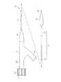
以下に、本発明を具体化した一実施の形態について図面を参照しつつ説明する。本実施形態では、バルーンカテーテルのハブに対して取り付けられる止血用コネクタについて具体化している。図1は、バルーンカテーテルの構成を示す概略全体側面図である。[First Embodiment]
Hereinafter, an embodiment of the present invention will be described with reference to the drawings. In this embodiment, the hemostatic connector attached to the hub of the balloon catheter is embodied. FIG. 1 is a schematic overall side view showing the configuration of a balloon catheter.
図1に示すように、バルーンカテーテル10は、カテーテルチューブ11と、カテーテルチューブ11の基端部(近位端部)に取り付けられたハブ12と、カテーテルチューブ11の先端側(遠位端側)に取り付けられたバルーン13とを備える。カテーテルチューブ11は、外側チューブ15と、その外側チューブ15に内挿された内側チューブ16とを備え、それら両チューブ15,16による二重管構造をなしている。 As shown in FIG. 1, the
外側チューブ15は、管状に形成されており、その内部に軸線方向全域に亘って延びる外側管孔18(図2参照)を有している。外側チューブ15は、基端側チューブ22と、その基端側チューブ22よりも先端側(遠位側)に設けられた先端側チューブ23とを備え、それら両チューブ22,23が互いに接合されることにより構成されている。基端側チューブ22は、ナイロンなどの樹脂材料により形成され、その基端部がハブ12に対して接続されている。先端側チューブ23は、基端側チューブ22に比べて剛性の低い樹脂材料により形成され、その先端部がバルーン13の基端部に対して接合されている。 The
外側チューブ15の外側管孔18はバルーン13の内側空間に通じている。外側管孔18は、バルーン13を膨張又は収縮させる際に圧縮流体が流通する流体用ルーメンとなっており、この外側管孔18を通じて圧縮流体が当該バルーン13内に供給されるとバルーン13が膨張状態となり、外側管孔18に陰圧が付与されて圧縮流体がバルーン13内から排出されるとバルーン13が収縮状態となる。 The
内側チューブ16は、樹脂材料により管状に形成されており、その内部に軸線方向全域に亘って延びる内側管孔19(図2参照)を有している。内側チューブ16は、その基端部がハブ12に対して接続されている。また、内側チューブ16は、外側チューブ15よりも先端側に延出しており、その延出部分がバルーン13により外側から覆われている。当該延出部分の先端部は、バルーン13の先端部に接合されている。 The
内側チューブ16の内側管孔19は、ガイドワイヤGが挿通されるガイドワイヤ用ルーメンとなっている。内側管孔19は、バルーンカテーテル10の先端から基端側へ向けてハブ12まで延びている。つまり、本バルーンカテーテル10は所謂オーバー・ザ・ワイヤ型のカテーテルとなっている。 The
また、本バルーンカテーテル10では、内側チューブ16の内側管孔19の孔径D1が0.95mmに設定されている。この場合、ガイドワイヤGとしては、その外径D2が0.889mm(0.035インチ)のものを用いることが適切であるが、本実施形態では、ガイドワイヤGとしてそれよりも外径D2の小さいもの、具体的には外径D2が0.3556mm(0.014インチ)又は0.4572mm(0.018インチ)のものを用いることとしている。このため、内側管孔19にガイドワイヤGが挿通された状態において、ガイドワイヤGの外周面と内側管孔19の内周面との間に比較的大きな隙間が形成されるようになっている。 Further, in the
続いて、ハブ12の構成について図2に基づいて説明する。図2はハブ周辺の構成を示す縦断面図である。 Next, the configuration of the
図2に示すように、ハブ12は、ポリカーボネート等の合成樹脂材料によりY字状に形成されている。ハブ12は、管状をなす第1管部25と、第1管部25の途中位置から分岐させて設けられ、管状をなす第2管部26とを備える。第1管部25は、その軸線方向全域に亘って延びるとともに両端にて開放された管孔25aを有している。管孔25aは、その途中位置において第2管部26の管孔26aと連通している。なお、管孔25aがハブ内通路に相当する。 As shown in FIG. 2, the
第1管部25の管孔25aには、その先端側から外側チューブ15と内側チューブ16とが挿入されている。これら各チューブ15,16はそれぞれ、その挿入状態において第1管部25と接合されている。外側チューブ15の外側管孔18は第1管部25の管孔25aを介して第2管部26の管孔26aと連通している。これにより、第2管部26に加圧器等の流体供給機器(図示略)を接続することで、同機器より管孔26a及び外側管孔18を通じてバルーン13内へ圧縮流体を供給することが可能となっている。 The
なお、第1管部25の先端部には、柔軟性を有する樹脂材料により形成された補強部材34が取り付けられており、その補強部材34により外側チューブ15の基端側が覆われた状態となっている。 A reinforcing
内側チューブ16は、外側チューブ15よりも基端側に延出しており、その延出した部分が管孔25aの縮径部分28に入り込んでいる。管孔25aにおいて縮径部分28よりも基端側であってかつ当該管孔25aの基端を含む所定範囲は、当該基端に向かうにつれて孔径が大きくされた拡径部分29となっている。この拡径部分29では、その内周面が予め規格化された形状を有するテーパ面29aとなっている。 The
また、第1管部25の基端部には、その外周面に環状の突出部37が設けられている。その突出部37にはおねじ部(図示略)が形成されている。 An annular projecting
ハブ12の第1管部25には、その基端側に止血用コネクタ30が接続されている。以下、この止血用コネクタ30の構成について図3に基づいて説明する。なお、図3は、止血用コネクタ30の構成を示しており、(a)が同構成を示す正面図、(b)が軸線方向の一方側から見た図、(c)が縦断面図、(d)が分解縦断面図である。なお、図3(c)及び(d)はいずれも、図3(b)のA−A線断面図に相当する。 A
図3(a)〜(d)に示すように、止血用コネクタ30(以下、単にコネクタという)は、本体部31と、止血弁32と、キャップ部33とを有する。本体部31は、透明性又は半透明性を有する樹脂材料により形成されており、例えばポリカーボネートにより形成されている。本体部31は、有底の円筒状に形成された筒状部35と、その筒状部35の底板部35aから筒状部35の内側へ向けて延びる接続部36とを有する。なお、本体部31は、必ずしも透明性又は半透明性を有していなくてもよく、着色された樹脂材料により形成されていてもよい。 As shown in FIGS. 3A to 3D, the hemostatic connector 30 (hereinafter simply referred to as a connector) has a
筒状部35において接続部36を囲む周壁部38には、その内周面にめねじ部39が形成されている。また、周壁部38の外周面には、軸線方向に延びる複数のリブ41が周方向に所定間隔(詳しくは等間隔)で形成されている。これらのリブ41により、筒状部35の強度が高められているとともに、筒状部35を手に持ってコネクタ30をハブ12に接続する際手が滑ることが抑制されている。 An
筒状部35の底板部35aは円板状に形成されている。この底板部35aには、軸線方向において接続部36側とは反対側に突出する凸部42が形成されている。この凸部42は、底板部35aよりも外径の小さい円形状をなしており、その外周面に周方向全域に亘って延びる溝部43が形成されている。 The
接続部36は、筒状部35と同軸に延びる円管状(円筒状)をなしており、その一部が筒状部35よりも底板部35aとは反対側(換言すると止血弁32とは反対側)に延出している。接続部36には、その内部にガイドワイヤGが挿通される挿通孔部45が形成されている。挿通孔部45は、接続部36のみならず底板部35aにも跨がって延びており、接続部36及び底板部35a(換言すると本体部31)を軸線方向に貫通している。なお、挿通孔部45が案内通路部に相当する。 The connecting
挿通孔部45は、その孔径が、軸線方向において底板部35a側(換言すると止血弁32側)の端部から反底板部35a側(換言すると反止血弁32側)の端部へ向けて徐々に大きくなっている。換言すると、挿通孔部45は、反止血弁32側から止血弁32側へ向けて徐々に縮径されたテーパ形状をなしている。これにより、挿通孔部45における軸線方向両端の開口のうち、止血弁32側の開口45aはその開口径(換言すると開口面積)が小さくなっているのに対して、反止血弁32側の開口45bはその開口径が大きくなっている。具体的には、開口45aの開口径はガイドワイヤGの外径D2よりも若干大きい寸法に設定されており、例えば0.5mmに設定されている。それに対して、開口45bの開口径はガイドワイヤGの外径D2よりも十分大きい寸法に設定されており、例えば3.4mmに設定されている。 The hole diameter of the
また、挿通孔部45の内周面には、その反止血弁32側の端部にR部57(湾曲部)が形成されている。このR部57は、反止血弁32側に向かうにつれて挿通孔部45の径方向外側に湾曲するように形成されている。このR部57が形成されていることで接続部36は、その反止血弁32側の端部においてエッジ状をなしている(肉厚が極めて薄くなっている)。但し、反止血弁32側の端部がエッジ状をなすのであれば、R部57(湾曲部)に代えて直線状のテーパ部としてもよい。 Further, an R portion 57 (curved portion) is formed on the inner peripheral surface of the
なお、挿通孔部45における止血弁32側の端部には、一定の孔径(テーパの最小径)で形成された短い小径部47が形成されている。 A short small-
止血弁32は、シリコンゴム等の弾性を有する材料により円板状に形成されている。止血弁32は、底板部35a(凸部42)において接続部36側とは反対側の面に設けられ、凸部42に対して同軸に配置されている。止血弁32には、その厚み方向に貫通する複数(本実施形態では3つ)のスリット48が形成されている(図3(b)参照)。これらのスリット48はそれぞれ、止血弁32の中心部から径方向外側へ向けて放射状に延びている。具体的には、各スリット48は、後述するキャップ部33の貫通孔部54よりも径方向外側まで延びている。 The
止血弁32の中心部は各スリット48同士が互いに連通するスリット連通部49となっている。なお、このスリット連通部49が絞り通路部に相当する。スリット連通部49は、本体部31の挿通孔部45(開口45a)の軸線延長上に位置しており、開口45aを介して挿通孔部45と連通している。また、各スリット48は、通常状態(自然状態)では、対向するスリット内面同士が互いに当接又は近接している。 The central portion of the
なお、放射状に形成されるスリット48の個数は必ずしも3つに限ることなく、4つ以上であってもよい。 The number of radially formed slits 48 is not necessarily limited to three and may be four or more.
キャップ部33は、円柱状をなしており、その軸線方向の一方側に開放された凹部51を有している。キャップ部33は、その凹部51に止血弁32を収容した状態で本体部31の凸部42に被せられている。キャップ部33において凹部51を囲む周壁部52には、その内周面に周方向に延びる突出部53が形成されている。この突出部53は、凸部42の溝部43に入り込んで当該溝部43と係合されており、その係合によってキャップ部33が凸部42ひいては本体部31に取り付けられている。 The
キャップ部33において凹部51の底面を規定する底板部33aには、厚み方向に貫通する円形状の貫通孔部54が形成されている。この貫通孔部54により、止血弁32の一部詳しくは止血弁32において少なくともスリット連通部49を含む一部がコネクタ30外部に露出している。なお、この貫通孔部54と止血弁32のスリット48(スリット連通部49)と本体部31の挿通孔部45とにより本コネクタ30の挿通通路50が構成されている。 A circular through-
続いて、上記コネクタ30のハブ12に対する取付構成について図2を参照しながら説明する。 Next, a configuration for attaching the
上述したように、コネクタ30は、ハブ12の第1管部25に対して基端側から接続されている。コネクタ30において本体部31の接続部36は第1管部25の管孔25a詳しくは拡径部分29に基端側から挿入されており、その挿入状態において拡径部分29の内周面(テーパ面29a)に液密状態で嵌合されている。この嵌合によって、接続部36が第1管部25と接続されている。また、かかる接続状態において、本体部31の筒状部35は第1管部25の外周側に位置し、そのめねじ部39が第1管部25の突出部37のおねじ部に締結されている。これにより、本体部31ひいてはコネクタ30がハブ12に対して取り付けられている。 As described above, the
なお、バルーンカテーテル10と、そのハブ12に取り付けられたコネクタ30とによって「コネクタ付きカテーテル」が構成されている。 The
次に、上述したコネクタ30の作用について説明する。以下においては、コネクタ30をバルーンカテーテル10のハブ12に取り付けて同カテーテル10を体内に導入する際における作用を説明する。なお、カテーテル10の導入作業に際しては予めハブ12にコネクタ30を取り付けておく。また、上述したように、本実施形態(後述する第2の実施形態でも)では、ガイドワイヤGとして、その外径D2が内側管孔19の孔径D1に対して小さめのものを用いることとしている。 Next, the operation of the
導入作業に際しては、先ず血管内に挿入されたシースイントロディーサにガイディングカテーテルを挿通し、ガイディングカテーテルの先端開口部を血管内における狭窄部位等の治療対象部位付近まで導入する。次いで、ガイドワイヤGをガイディングカテーテル内に挿通し、その挿通したガイドワイヤGを治療対象部位を越える位置まで導入する。 In the introduction operation, first, a guiding catheter is inserted into a sheath introducer inserted into a blood vessel, and the distal end opening of the guiding catheter is introduced to the vicinity of a treatment target site such as a stenosis site in the blood vessel. Next, the guide wire G is inserted into the guiding catheter, and the inserted guide wire G is introduced to a position beyond the treatment target site.
次に、体内に導入したガイドワイヤGをバルーンカテーテル10内に挿通する作業を行う。この作業では、ガイドワイヤGを、内側チューブ16の先端開口より内側管孔19に導入し、それからハブ12の管孔25aとコネクタ30の挿通通路50とを通じて基端側へと導出させる。これにより、ガイドワイヤGがバルーンカテーテル10に挿通される。なお、ガイドワイヤGをバルーンカテーテル10に挿通する際には、内側管孔19に空気(エア)が存在しているため、コネクタ30を一時的にハブ12から取り外してエア抜きを行うことが望ましい。 Next, an operation of inserting the guide wire G introduced into the body into the
ここで、ガイドワイヤGをコネクタ30の挿通通路50に導入するにあたっては、まずガイドワイヤGをハブ12の管孔25aから本体部31の挿通孔部45へその端部開口45bを介して導入する。この場合、挿通孔部45は、端部開口45a(基端開口)においてその開口径がガイドワイヤGの外径寸法と同程度まで狭められているにもかかわらず、端部開口45b(先端開口)ではその開口径がガイドワイヤGの外径寸法に対して十分大きなものとなっているため、ガイドワイヤGを挿通孔部45へ容易に導入することが可能となっている。 Here, when the guide wire G is introduced into the
また、挿通孔部45の内周面にはその先端部にR部57が形成され、そのR部57によって接続部36の先端がエッジ状をなしているため、ガイドワイヤGを挿通孔部45に端部開口45bを通じて導入する際に、ガイドワイヤGが接続部36の先端に引っ掛かってしまうことが抑制されている。そのため、この点においても、ガイドワイヤGを挿通孔部45へ導入し易くなっている。 Further, an
その後、ガイドワイヤGを挿通孔部45において基端側(止血弁32側)へと押し進め、端部開口45aを介して止血弁32のスリット48へと導入する。この際、挿通孔部45は、その孔径が基端側へ向かうにつれて徐々に小さくなっているため、ガイドワイヤGが基端側へ押し進められるとガイドワイヤGは自ずとスリット連通部49へ導かれる。これにより、ガイドワイヤGを、局所的な部位であるスリット連通部49へ容易に挿通させることが可能となっている。 Thereafter, the guide wire G is pushed toward the proximal end side (the
ガイドワイヤGがスリット48に挿通された状態では、ガイドワイヤGの外周面に止血弁32のスリット内面が密接された状態となっている。詳しくは、止血弁32の弾性力によってガイドワイヤGの外周面にスリット内面が圧接された状態となっている。また、本実施形態では、ガイドワイヤGがスリット連通部49に挿通されるため、ガイドワイヤGの外周面における広い範囲にスリット内面が密接された状態となっている。なお、ガイドワイヤGがスリット連通部49に挿通された状態では、同連通部49の開口面積(通路断面積)が内側チューブ16の内側管孔19の通路断面積よりも小さくなっており、詳細にはガイドワイヤGの横断面積よりも若干大きくなっている。 In the state where the guide wire G is inserted through the
また、絞り通路部を上記のようなスリット構造としたことで、ガイドワイヤGを絞り通路部(スリット48)に押し込んで挿通させる際それ程大きな押し込み力を付与しなくてもよく、そのため、極細状であるが故にその強度も小さいことが想定されるガイドワイヤGであっても、比較的容易に密着状態での挿通を実現することが可能となる。特に、本実施形態では、絞り通路部をスリット連通部49により構成したため、ガイドワイヤGの外周面が隣り合うスリット48同士の境界部となるスリット角部にてスリット内面に密接される。このため、ガイドワイヤGをスリット48に押し込む際に発生するガイドワイヤGの外周面とスリット内面との接触抵抗を極めて小さくすることができ、その結果ガイドワイヤGをスリット48に押し込む際の押し込み力を極めて小さくすることが可能となる。 Further, since the throttle passage portion has the slit structure as described above, when the guide wire G is pushed through the throttle passage portion (slit 48) and inserted therethrough, it is not necessary to apply such a large pushing force. Therefore, even in the case of the guide wire G whose strength is assumed to be small, it is possible to realize insertion in a close contact state relatively easily. In particular, in the present embodiment, since the throttle passage portion is constituted by the
次に、かかるガイドワイヤGの挿通状態において、バルーンカテーテル10をガイドワイヤGに沿わせながらガイディングカテーテル内に導入し、押引操作を加えながら治療部位にバルーン13を配置させる作業を行う。ここで、本実施形態では、ガイドワイヤGとして、その外径D2が内側管孔19の孔径D1に対して小さめのものが用いられていることから、ガイドワイヤGの外周面と内側管孔19の内周面との間に比較的大きな隙間が形成されている。そのため、バルーンカテーテル10の導入に際し、その隙間を通じて基端側へ血液が流れ易くなっていると考えられ、ハブ12の管孔25aを通じて血液が外部に漏れ出してしまうことが懸念される。 Next, in the inserted state of the guide wire G, the
この点、上述したように、止血弁32のスリット連通部49では、ガイドワイヤGの外周面における広い範囲にスリット内面が密接し、当該外周面とスリット内面との間の隙間が極めて小さいものとなっているため、内側管孔19における上記隙間を通じて血液が流れ易くなっていても、その血液の流れをスリット連通部49において抑制することができる。これにより、バルーンカテーテル10の体内への導入に際し、血液漏れの抑制を図ることができる。 In this regard, as described above, in the
また、止血弁32の弾性力によってガイドワイヤGの外周面にスリット内面が圧接されているため、ガイドワイヤGの外周面とスリット内面との密接部分において血液漏れを確実に防止することができる。これにより、止血性能の向上を図ることができる。 Further, since the inner surface of the slit is pressed against the outer peripheral surface of the guide wire G by the elastic force of the
また、コネクタ30の挿通通路50において一部にのみスリット連通部49(絞り通路部)を設け、それ以外の部分にスリット連通部49よりも通路断面積が拡張された拡張通路部(具体的には本体部31の挿通孔部45)を設けたため、挿通通路50の軸線方向全域を絞り通路部とする場合に比べて、バルーンカテーテル10を体内へ導入する際におけるガイドワイヤGの外周面と挿通通路50の内周面との間の摺動抵抗を低減させることができる。これにより、バルーンカテーテル10の導入作業をし易くすることができる。 In addition, a slit communication portion 49 (throttle passage portion) is provided only in a part of the
バルーン13を狭窄箇所に配置した後、加圧器を用いてハブ12側から外側チューブ15の外側管孔18を介してバルーン13に圧縮流体を供給する。これにより、バルーン13が膨張し、その膨張したバルーン13により狭窄箇所が拡張される。 After the
〔第2の実施形態〕
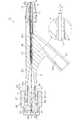
本実施形態では、上記第1の実施形態とは止血用コネクタの構成が相違する。以下、本実施形態における止血用コネクタの構成について図4に基づいて説明する。図4は、本実施形態における止血用コネクタの構成を示しており、(a)が同構成を示す正面図、(b)が軸線方向の一方側から見た図、(c)が縦断面図である。なお、図4(c)は図4(b)のB−B線断面図に相当する。[Second Embodiment]
In this embodiment, the configuration of the hemostatic connector is different from that of the first embodiment. Hereinafter, the configuration of the hemostatic connector according to the present embodiment will be described with reference to FIG. 4A and 4B show the configuration of the hemostatic connector in the present embodiment, in which FIG. 4A is a front view showing the configuration, FIG. 4B is a view seen from one side in the axial direction, and FIG. It is. FIG. 4C corresponds to a cross-sectional view taken along the line BB in FIG.
止血用コネクタ60(以下、単にコネクタという)は、透明性又は半透明性を有するゴム材料からなるボディ61を有する。ボディ61は、例えばシリコンゴムにより形成されている。但し、ボディ61は、必ずしも透明性又は半透明性を有している必要はなく、着色されたゴム材料により形成されていてもよい。 The hemostatic connector 60 (hereinafter simply referred to as a connector) has a
ボディ61は、図4(a)及び(b)に示すように、全体として円柱状をなしており、具体的には軸線方向における一端側から他端側に向けて外径が徐々に小さくなるテーパ形状を有している。ここで、本明細書において、「円柱状」とは、厳密な意味での円柱状、すなわち軸線方向全域に亘って外径が一定である形状のみを指すものではなく、軸線方向における一部又は全部に同方向における一端側から他端側に向けて外径が徐々に小さくなる形状(つまるテーパ形状)を有するものを含む意味となっている。また、本ボディ61は円錐状をなしていると言うこともできるが、本明細書において「円柱状」とはかかる「円錐状」をも含む概念となっている。 As shown in FIGS. 4A and 4B, the
上記構成のボディ61には、軸線方向の両端に互いに平行をなす平坦状の一対の端面部62,63が形成され、それら両端面部62,63の間に曲面状の側面部64が形成されている。また、本実施形態では、ボディ61の外径が、当該ボディ61の軸線方向の中央位置でハブ12(第1管部25)の管孔25a(詳しくは拡径部分29)の基端開口27における開口径と略同じ寸法となっている。 The
なお、以下の説明において、単に一端側という場合には、ボディ61の軸線方向における外径の大きい端面部62側のことをいい、他端側という場合には、外径の小さい端面部63側のことをいう。なお、本コネクタ60では、ボディ61全体がテーパ部に相当する。 In the following description, when it is simply referred to as one end side, it refers to the
図4(c)に示すように、ボディ61には、ガイドワイヤGが挿通される挿通孔部65が形成されている。挿通孔部65は、ボディ61の中心部を軸線方向に貫通して延びており、各端面部62,63にてそれぞれ外部に開口されている。挿通孔部65の各端部開口65a,65bのうち、端部開口65aが端面部62にて開口され、端部開口65bが端面部63にて開口されている。なお、挿通孔部65が挿通通路に相当する。 As shown in FIG. 4C, the
挿通孔部65は、端部開口65aから他端側へ向けて孔径が徐々に小さくなるように形成された第1孔部66と、第1孔部66の他端から他端側へ向けて一定の孔径で形成された第2孔部67と、第2孔部67の他端から他端側へ向けて孔径が徐々に大きくなるように形成されているとともに端部開口65bを含む第3孔部68とを有している。第1孔部66と第2孔部67とは互いの通路断面が連続しており、第2孔部67と第3孔部68とは互いの通路断面が連続している。そのため、第1孔部66と第2孔部67との境界部、及び第2孔部67と第3孔部68との境界部ではいずれも挿通孔部65の内周面に径方向への段差が生じていない。 The
なお、この場合、第1孔部66が拡張通路部に相当し、第2孔部67が絞り通路部に相当し、第3孔部68が拡張通路部に相当する。 In this case, the
第1孔部66と、第2孔部67と、第3孔部68とはいずれも同じ長さで形成されている。また、第1孔部66と第3孔部68とはいずれも同じテーパ形状を有している。したがって、挿通孔部65は、その軸線方向における中心位置を基準として対称形状をなしている。但し、各孔部66〜68の長さは必ずしも同じとする必要はなく、互いに異ならせてもよい。また、第1孔部66のテーパ形状(テーパ角度)と第3孔部68のテーパ形状(テーパ角度)とを互いに異ならせてもよい。 The
第2孔部67は、その孔径D3が内側チューブ16の管孔19の孔径D1よりも小さい寸法に設定されている。具体的には、第2孔部67の孔径D3はガイドワイヤGの外径D2よりも若干大きい寸法に設定されており、本実施形態では、その孔径D3が0.6mmに設定されている。一方、第1孔部66及び第3孔部68の各端部開口65a,65bはその開口径がいずれもガイドワイヤGの外径D2よりも十分大きい寸法に設定されている。本実施形態では、端部開口65a,65bの開口径が2.0mmに設定されている。 The
ボディ61には、側面部64から挿通孔部65の内周面にかけて切り込まれ、かつ、端面部62から端面部63にかけて切り込まれたスリット71が形成されている。このスリット71を介して挿通孔部65がボディ61側方に開放されている。なお、スリット71が切り込み部に相当する。 The
続いて、上記コネクタ60のハブ12に対する取付構成について図5に基づいて説明する。図5は、止血用コネクタ60がハブ12に取り付けられた状態を示す縦断面図である。 Next, the mounting configuration of the
図5に示すように、コネクタ60は、ハブ12の第1管部25の基端側に接続されている。コネクタ60は、その軸線方向における他端側すなわち外径が小さくなっている側を挿し込み先端として第1管部25の管孔25aに基端側から挿し込まれている。具体的には、コネクタ60は、その軸線方向における半分程度の長さ分が管孔25aに挿し込まれ、その挿し込みによって第1管部25の基端部に接続されている(取り付けられている)。また、この挿し込み状態において、コネクタ60の側面部64と管孔25a(詳しくは拡径部分29)のテーパ面29aとは互いに密着しており、それによってそれら両面64,29a間を通じた管孔25aから基端側への血液漏れが防止されている。 As shown in FIG. 5, the
コネクタ60のかかる接続状態では、コネクタ60の挿通孔部65が、その端部開口65bを介して第1管部25の管孔25aと連通され、その端部開口65aを介して外部に開放されている。つまり、挿通孔部65を介してハブ12の管孔25aが外部に開放されている。なお、かかるコネクタ60の接続状態では、挿通孔部65の第2孔部67が管孔25aの基端開口27と軸線方向で同位置に位置している。 In such a connected state of the
なお、バルーンカテーテル10と、そのハブ12に取り付けられたコネクタ60とによって「コネクタ付きカテーテル」が構成されている。 The
次に、上述したコネクタ60の作用について説明する。なお、以下においても、上記第1の実施形態と同様、コネクタ60をバルーンカテーテル10のハブ12に取り付けて同カテーテル10を体内に導入する際における作用を説明する。また、本実施形態では、バルーンカテーテル10の導入に際し、まず同カテーテル10にコネクタ60を取り付けないでおく。 Next, the operation of the
導入作業に際しては、先ず血管内に挿入されたシースイントロディーサにガイディングカテーテルを挿通し、次いで、ガイドワイヤGをガイディングカテーテル内に挿通し、その挿通したガイドワイヤGを治療対象部位を越える位置まで導入する。 In the introduction operation, first, the guiding catheter is inserted into the sheath introducer inserted into the blood vessel, then the guide wire G is inserted into the guiding catheter, and the inserted guide wire G crosses the site to be treated. Introduce to position.
次に、体内に導入したガイドワイヤGをバルーンカテーテル10内に挿通する。この場合、ガイドワイヤGを、内側チューブ16の先端開口より内側管孔19に導入し、それからハブ12の管孔25aを通じて基端側へ導出させる。これにより、ガイドワイヤGがバルーンカテーテル10に挿通される。 Next, the guide wire G introduced into the body is inserted into the
次に、バルーンカテーテル10の基端側に導出されたガイドワイヤGをコネクタ60の挿通孔部65に挿通させる作業を行う。この作業では、ガイドワイヤGを、スリット71を通じて挿通孔部65に導入し挿通させる。この場合、ガイドワイヤGを端部開口65bから挿通孔部65に導入する場合と比べ、ガイドワイヤGを挿通孔部65に容易に導入することができる。 Next, an operation of inserting the guide wire G led out to the proximal end side of the
次に、コネクタ60をハブ12の基端側に接続する作業を行う。この作業では、コネクタ60(ボディ61)の他端側(先細り側)をハブ12の管孔25aに基端側から挿し込むことにより、コネクタ60をハブ12に対して接続する。この場合、コネクタ60を管孔25aに挿し込むだけで接続することができるため、コネクタ60のハブ12への接続作業を速やかに行うことができる。 Next, an operation of connecting the
次に、コネクタ60が接続されたバルーンカテーテル10をガイドワイヤGに沿って体内に導入する作業を行う。上述したように、本コネクタ60では、挿通孔部65の第2孔部67の孔径D3が内側チューブ16の内側管孔19の孔径D1よりも小さくなっているため、第2孔部67ではガイドワイヤGの外周面と挿通孔部65の内周面との隙間が極めて小さくなっている。そのため、バルーンカテーテル10を体内に導入するに際し、血液がガイドワイヤGの外周面と内側管孔19の内周面との隙間を通じて基端側に流れ易くなっていても、その血液の流れを第2孔部67において抑制することができる。これにより、バルーンカテーテル10の体内への導入に際し、血液漏れの抑制を図ることができる。 Next, the operation of introducing the
また、挿通孔部65において軸線方向の一部にのみ第2孔部67(絞り通路部)を設け、それ以外の部分を第2孔部67よりも孔径の大きい第1孔部66及び第3孔部68(拡張通路部)としたため、挿通孔部65の軸線方向全域を絞り通路部とする場合に比べて、バルーンカテーテル10を体内へ導入する際におけるガイドワイヤGの外周面と挿通孔部65の内周面との間の摺動抵抗を低減させることができる。これにより、バルーンカテーテル10の導入作業をし易くすることができる。 In addition, the second hole 67 (throttle passage portion) is provided only in a part of the axial direction in the
〔他の実施形態〕
本発明は上記実施形態に限らず、例えば次のように実施されてもよい。[Other Embodiments]
The present invention is not limited to the above embodiment, and may be implemented as follows, for example.
(1)上記第2の実施形態では、コネクタ60(ボディ61)にスリット71を設けたが、スリット71は必ずしも設ける必要はない。その場合でも、上記第1の実施形態と同様に、コネクタ60の挿通孔部65に端部開口65bよりガイドワイヤGを導入することができる。 (1) In the second embodiment, the connector 71 (body 61) is provided with the
この場合、挿通孔部65において第2孔部67(絞り通路部)の基端側(換言するとハブ12側)に当該孔部67よりも孔径の大きい第3孔部68(拡張通路部)が設けられ、端部開口65bの開口径がガイドワイヤGの外径D2に対して十分大きい寸法に設定されているため、端部開口65bよりガイドワイヤGを挿通孔部65へ導入する作業を比較的容易に行うことができる。 In this case, the third hole portion 68 (expansion passage portion) having a larger hole diameter than the
また、第3孔部68は、その孔径がハブ12側(先端側)から第2孔部67側(基端側)に向かうにつれて徐々に小さくなるテーパ形状を有しているため、ガイドワイヤGを第3孔部68から第2孔部67へ向けて押し進めていく際、ガイドワイヤGを第2孔部67へ容易に導くことができる。 Further, since the
さらに、第2孔部67と第3孔部68とは、互いの通路断面が両孔部67,68の境界部において連続しているため、当該境界部において挿通孔部65の内周面に径方向への段差が生じていない。このため、ガイドワイヤGを第3孔部68から第2孔部67へ導入する際に、ガイドワイヤGがかかる段差に引っ掛かって導入しづらくなるといった不都合を生じにくくすることができる。なお、この場合、第3孔部68がテーパ通路部に相当する。 Further, since the
ちなみに、コネクタ60にスリット71が設けられた上記第2の実施形態において、ガイドワイヤGをコネクタ60の挿通孔部65に端部開口65bを通じて導入するようにしてもよい。その場合にも、上述した各効果を得ることができる。 Incidentally, in the second embodiment in which the
(2)上記第1の実施形態では、止血弁32に形成された複数のスリット48におけるスリット連通部49を絞り通路部としたが、スリット連通部49以外の部位例えばスリット48の(長さ方向の)中間部分を絞り通路部としてもよい。この場合にも、スリット48にガイドワイヤGを挿通した状態で、ガイドワイヤGの外周面にスリット内面を密着させるようにすることで、ガイドワイヤGの挿通状態における止血性能を高めることができる。また、このようなスリット構造であれば、ガイドワイヤGをスリット48(絞り通路部)に押し込んで挿通させる際それ程大きな押し込み力を付与しなくても、スリット48を押し拡げて挿通することができるため、極細状であるが故にその強度も小さいことが想定されるガイドワイヤGであっても、比較的容易に密着状態での挿通を実現することができる。 (2) In the first embodiment, the
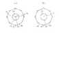
(3)止血弁32に形成されるスリット48の構成は必ずしも上記第1の実施形態に記載されたものに限定されない。例えば図6(a)に示すように、各スリット73を、止血弁32の中心部付近にて短い長さ(例えば挿通孔部45の開口45aの開口径の半分程度の長さ)で形成してもよい。この場合にも、止血弁32の中心部に各スリット73が互いに連通するスリット連通部74が形成されている。また、図6(b)に示すように、スリット75を一文字に形成してもよい。図6(b)では、一文字のスリット75が止血弁32の中心部付近に短い長さ(例えば挿通孔部45の開口45aの開口径と略同じ長さ)で形成されている。 (3) The configuration of the
これら図6(a)及び(b)の場合にも、ガイドワイヤGがスリット73,75に挿通された状態でガイドワイヤGの外周面にスリット内面が密着されるため、ガイドワイヤGの挿通状態における止血性能を高めることができる。また、ガイドワイヤGを絞り通路部(すなわちスリット73,75)に押し込んで挿通させる際それ程大きな押し込み力を付与しなくてもよいため、極細状であるが故にその強度も小さいことが想定されるガイドワイヤGであっても、比較的容易に密着状態での挿通を実現することが可能となる。 6 (a) and 6 (b), since the inner surface of the slit is in close contact with the outer peripheral surface of the guide wire G while the guide wire G is inserted into the
(4)上記第2の実施形態では、コネクタ60全体をテーパ形状に形成したが、コネクタ60の軸線方向の一部だけをテーパ形状に形成してもよい。例えば、コネクタにおいて軸線方向の一端を含む一部分だけを当該一端に向けて先細りしたテーパ形状とし、それ以外の部分を円柱形状(詳細には、厳密な意味での円柱形状)とすることが考えられる。その場合でも、コネクタのテーパ部分をハブ12の管孔25aに挿し込むだけで接続ができるため、コネクタのハブ12への接続を速やかに行うことができる。 (4) In the second embodiment, the
(5)上記第2の実施形態では、拡張通路部としての第1孔部66及び第3孔部68をそれぞれテーパ形状に形成したが、それら各孔部66,68のうち少なくともいずれか一方を非テーパ形状としてもよい。すなわち、各孔部66,68のうち少なくともいずれか一方を第2孔部67の孔径D3よりも大きい一定の孔径で形成してもよい。 (5) In the second embodiment, the
また、上記第2の実施形態では、第1孔部66及び第3孔部68をそれぞれ拡張通路部としたが、それら各孔部66,68のうちいずれか一方を第2孔部67と連続する絞り通路部としてもよい。その場合であっても、挿通孔部65の軸線方向全域を絞り通路部とする場合と比べ、ガイドワイヤGの外周面と挿通孔部65の内周面との間の摺動抵抗を低減させることができる。なお、挿通孔部65の軸線方向全域を絞り通路部としてもよい。 In the second embodiment, the
(6)上記第2の実施形態では、第2孔部67の孔径D3をガイドワイヤGの外径D2よりも若干大きい寸法に設定したが、第2孔部67の孔径D3をガイドワイヤGの外径D2と同じ寸法か又はそれよりも小さい寸法に設定してもよい。例えば、第2孔部67の孔径D3をガイドワイヤGの外径D2よりも小さい寸法に設定すれば、ガイドワイヤGの外周面と第2孔部67の内周面との間に隙間を生じないようにすることができるため、第2孔部67において基端側へ向けた血液の流れを防止することができる。そのため、ガイドワイヤGに沿ってバルーンカテーテル10を体内へ導入する際における血液漏れの防止を図ることが可能となる。 (6) In the second embodiment, the hole diameter D3 of the
(7)上記第2の実施形態では、ボディ61が弾性を有するゴム材料により形成されているため、ボディ61をハブ12に対して接続する際、ボディ61のハブ12の管孔25aへの挿し込み量(押し込み量)を調整することで、ボディ61の径方向への圧縮量を調整することができ、ひいては第2孔部67の孔径D3を大小調整することが可能となる。そこで、この点に着目し、ボディ61(テーパ部)の管孔25aへの挿し込み量を調整することで、第2孔部67の孔径D3を大小調整するようにしてもよい。具体的には、ボディ61の管孔25aへの挿し込み量(押し込み量)を大きくすることで第2孔部67の孔径D3を小さくし、ボディ61の管孔25aへの挿し込み量(押し込み量)を小さくすることで第2孔部67の孔径D3を大きくする。 (7) In the second embodiment, since the
この場合、第2孔部67の孔径D3を小さくすることで、ガイドワイヤGの外周面と第2孔部67の内周面との隙間を小さくすることができる又は当該隙間をなくすことができるため、止血性能を高めることができる。また、第2孔部67の孔径D3を大きくすることで、ガイドワイヤGの外周面と第2孔部67の内周面との摺動抵抗を低減させることができるため、バルーンカテーテル10の体内への導入作業をし易くすることができる。よって、この場合、カテーテル導入時における止血性能と作業性(操作性)とのバランスを図ることが可能となる等、その導入作業をより好適に行うことが可能となる。 In this case, by reducing the hole diameter D3 of the
なお、上記の構成を採用する場合、管孔25aへのボディ61の挿し込み量が、予め定められた所定の調整範囲におけるいずれの量に設定された場合にも、第2孔部67が管孔25aの基端開口27と軸線方向で同位置を含むように形成されていることが望ましい。 In addition, when employ | adopting said structure, even if the insertion amount of the
(8)上記各実施形態ではいずれも、コネクタ30,60のゴム部分に絞り通路部(具体的にはスリット連通部49、第2孔部67)を形成したが、絞り通路部は必ずしもゴム部分に形成する必要はない。例えば、上記第1の実施形態において、止血弁32を不具備とし、合成樹脂製からなる本体部31の挿通孔部45の一部に絞り通路部を形成することが考えられる。具体的には、挿通孔部45の一部(例えば小径部47)の孔径を、内側管孔19の孔径D1よりも小さい寸法に設定することで絞り通路部を形成する。この場合にも、絞り通路部においてガイドワイヤGの外周面と挿通孔部45の内周面との隙間を極めて小さくすることができるため、当該通路部において血液の流れを抑制することができ、血液漏れの抑制を図ることができる。 (8) In each of the above embodiments, the restricting passage portion (specifically, the
(9)上記各実施形態では、0.035インチのガイドワイヤGに適合するバルーンカテーテル10に本発明のコネクタ30,60を取り付けて、同カテーテル10を0.014インチ又は0.018インチのガイドワイヤGを用いて体内に導入した。この場合、コネクタ30,60を販売する際の販売形態を考えると、コネクタ30,60を単品で販売することに加えて、コネクタ30,60とバルーンカテーテル10(0.035インチガイドワイヤG適合品)とをセットにした状態(組み合わせた状態)での販売、コネクタ30,60とガイドワイヤG(0.014インチ品又は0.018インチ品)とをセットにした状態での販売が考えられる。また、コネクタ30,60、バルーンカテーテル10(0.035インチガイドワイヤG適合品)及びガイドワイヤG(0.014インチ品又は0.018インチ品)をセットにした状態で販売してもよい。 (9) In each of the above embodiments, the
また、コネクタ30,60とバルーンカテーテル10とをセットで販売する際には、バルーンカテーテル10のハブ12の基端側にコネクタ30,60を接続した状態(コネクタ付きカテーテルの状態)で販売してもよいし、ハブ12の基端側にコネクタ30,60を接続しないでバルーンカテーテル10とコネクタ30,60とをばらばらにした状態(コネクタカテーテルキットの状態)で販売してもよい。 Further, when the
(10)上記各実施形態では、本発明の止血用コネクタをバルーンカテーテルに接続して用いた場合を説明したが、本発明の止血用コネクタを吸引カテーテル等、他のカテーテルに接続して用いることもできる。要するに、ガイドワイヤGをカテーテル基端側から導出するオーバーザワイヤ型のカテーテルであれば、本発明の止血用コネクタを用いることができる。 (10) In each of the above embodiments, the case where the hemostatic connector of the present invention is connected to a balloon catheter has been described. However, the hemostatic connector of the present invention is used by being connected to another catheter such as a suction catheter. You can also. In short, the hemostasis connector of the present invention can be used in an over-the-wire type catheter in which the guide wire G is led out from the proximal side of the catheter.
10…カテーテルとしてのバルーンカテーテル、12…ハブ、19…ガイドワイヤルーメンとしての内側管孔、25a…ハブ内通路としての管孔、30…止血用コネクタ、31…本体部、32…止血弁、45…拡張通路部、本体通路部及び案内通路部としての挿通孔部、48…スリット、49…絞り通路部としてのスリット連通部、50…挿通通路、60…止血用コネクタ、61…ボディ、65…挿通通路としての挿通孔部、66…拡張通路部としての第1孔部、67…絞り通路部としての第2孔部、68…拡張通路部としての第3孔部、71…切り込み部としてのスリット、G…ガイドワイヤ。 DESCRIPTION OF
Claims (10)
Translated fromJapanese前記カテーテルは、
前記ガイドワイヤを挿通可能なガイドワイヤルーメンを有するカテーテルチューブと、
前記カテーテルチューブの基端部に設けられるとともに、前記ガイドワイヤルーメンと連通しかつ前記ガイドワイヤを挿通可能なハブ内通路を有するハブと、を備え、
前記ハブに接続した状態で用いられる止血用コネクタであって、
前記ハブの基端側に接続される接続部を有する本体部と、
その本体部に設けられた板状の止血弁と、
前記ハブとの前記接続状態において前記ハブ内通路と連通しかつ前記ガイドワイヤを挿通可能な挿通通路と、を備え、
前記挿通通路は、その軸線方向における一部が、前記ガイドワイヤルーメンよりも通路断面積が小さく絞られた絞り通路部とされており、
前記止血弁には、厚み方向に貫通するスリットが前記絞り通路部として形成されており、
前記本体部には、前記スリットと連通しかつ当該スリットとともに前記挿通通路を構成する本体通路部が形成されており、
前記ガイドワイヤが前記スリットに挿通された状態では、当該ガイドワイヤの外周面に前記止血弁のスリット内面が密接されるようになっており、
前記本体通路部は、前記スリットと前記ハブ内通路とを連通する案内通路部を有しており、
前記案内通路部は、前記ハブ内通路側から前記スリット側に向かうにつれて通路断面積が徐々に小さくなるように形成されていることを特徴とする止血用コネクタ。Applied to a catheter introduced into the guiding catheter along a guide wire previously inserted through the guiding catheter;
The catheter is
A catheter tube having an insertion can guidewire lumenthe guide wire,
A hub provided at the proximal end of the catheter tube and having a passage in the hub that communicates with the guide wire lumen and through which the guide wire can be inserted;
A hemostatic connector used in a state of being connected to the hub,
A main body having a connecting portion connected to the proximal end side of the hub;
A plate-like hemostasis valve provided in the main body,
An insertion passage that communicates with the passage in the hub and allows the guide wire to be inserted in the connection state with the hub,
The insertion passagepart that put in its axial direction,are a throttle passage which is cross-sectional area is narrowed smaller than the guide wirelumen,
In the hemostasis valve, a slit penetrating in the thickness direction is formed as the throttle passage portion,
The main body portion is formed with a main body passage portion that communicates with the slit and forms the insertion passage together with the slit,
In the state where the guide wire is inserted through the slit, the inner surface of the slit of the hemostasis valve is brought into close contact with the outer peripheral surface of the guide wire,
The main body passage portion has a guide passage portion that communicates the slit and the passage in the hub,
The hemostasis connector is characterized in that theguide passage portion is formed so that a passage cross-sectional area gradually decreases from the hub inner passage side toward the slit side .
それら複数のスリットは、前記止血弁の厚み方向から見て当該止血弁の所定位置を起点として放射状に延びており、
前記所定位置は、前記各スリットが互いに連通するスリット連通部となっており、そのスリット連通部が前記絞り通路部とされており、
前記案内通路部は、前記スリット連通部と前記ハブ内通路とを連通しており、前記ハブ内通路側から前記スリット連通部側に向かうにつれて通路断面積が徐々に小さくなるように形成されていることを特徴とする請求項1に記載の止血用コネクタ。The hemostasis valve is formed with a plurality of slits,
The plurality of slits extend radially from a predetermined position of the hemostasis valve as seen from the thickness direction of the hemostasis valve,
The predetermined position is a slit communication portion where the slits communicate with each other, and the slit communication portion is the throttle passage portion,
The guide passage portion, said slit communicating portion andhas communicating the hubpassage, and the passage sectional area asbefore Symbol hub passage side toward said slit communicating portion side is formed so as to gradually become smaller The hemostatic connector according to claim1 , wherein the connector is hemostatic.
前記カテーテルは、
前記ガイドワイヤを挿通可能なガイドワイヤルーメンを有するカテーテルチューブと、
前記カテーテルチューブの基端部に設けられるとともに、前記ガイドワイヤルーメンと連通しかつ前記ガイドワイヤを挿通可能なハブ内通路を有するハブと、を備え、
前記ハブに接続した状態で用いられる止血用コネクタであって、
前記ハブの基端側に接続される接続部と、
前記ハブとの前記接続状態において前記ハブ内通路と連通しかつ前記ガイドワイヤを挿通可能な挿通通路と、を備え、
前記挿通通路は、その軸線方向における少なくとも一部が、前記ガイドワイヤルーメンよりも通路断面積が小さく絞られた絞り通路部とされており、
前記挿通通路を内部に有するとともに、当該挿通通路の軸線方向に延びる円柱状のボディを備え、
前記ボディは、前記軸線方向における一端側から他端側に向かうにつれて外径が小さくなるように形成されたテーパ部を有しており、
前記テーパ部は、ゴム材料からなり、前記他端側を挿し込み先端として前記ハブ内通路に基端側から挿し込まれることで接続される前記接続部となっていることを特徴とする止血用コネクタ。Applied to a catheter introduced into the guiding catheter along a guide wire previously inserted through the guiding catheter;
The catheter is
A catheter tube having an insertion can guidewire lumenthe guide wire,
A hub provided at the proximal end of the catheter tube and having a passage in the hub that communicates with the guide wire lumen and through which the guide wire can be inserted;
A hemostatic connector used in a state of being connected to the hub,
A connecting portion connected to a proximal end side of the hub;
An insertion passage that communicates with the passage in the hub and allows the guide wire to be inserted in the connection state with the hub,
The insertion passage is at least a portion of the passage in the axial direction being a throttle passage portion in which a passage cross-sectional area is narrower than the guide wire lumen;
While having the insertion passage inside, a columnar body extending in the axial direction of the insertion passage,
The body has a tapered portion formed such that an outer diameter decreases as it goes from one end side to the other end side in the axial direction,
The taper portion is made of a rubber material and serves as the connection portion that is connected by being inserted from the proximal end side into the hub passage with the other end side inserted as a distal end . connector.
前記ボディには、前記挿通通路の内周面から当該ボディの外周面にかけて切り込まれ、かつ前記挿通通路の軸線方向全域に亘って切り込まれた切り込み部が設けられていることを特徴とする請求項3に記載の止血用コネクタ。The body is entirely formed of the rubber material,
The body is provided with a cut portion that is cut from the inner peripheral surface of the insertion passage to the outer peripheral surface of the body and is cut across the entire axial direction of the insertion passage. The hemostatic connector according to claim3 .
前記テーパ通路部と前記絞り通路部とは、互いの通路断面が両通路部の境界部にて連続していることを特徴とする請求項7に記載の止血用コネクタ。The tapered passage portion is formed continuously on the passage side in the hub with respect to the throttle passage portion,
The hemostatic connector according to claim7 , wherein the tapered passage portion and the throttle passage portion have a passage cross section that is continuous at a boundary portion between the two passage portions.
前記ハブの基端側に接続された請求項1乃至8のいずれか一項に記載の止血用コネクタと、を備えるコネクタ付きカテーテル。The catheter;
A hemostatic connector according to any one of claims 1 to8 , which is connected to a proximal end side of the hub.
前記ハブの基端側に接続される請求項1乃至8のいずれか一項に記載の止血用コネクタと、を備えるコネクタカテーテルキット。The catheter;
A connector catheter kit comprising the hemostatic connector according to any one of claims 1 to8 , which is connected to a proximal end side of the hub.
Priority Applications (1)
| Application Number | Priority Date | Filing Date | Title |
|---|---|---|---|
| JP2013155193AJP6247854B2 (en) | 2013-07-26 | 2013-07-26 | Hemostatic connector, catheter with connector and connector catheter kit |
Applications Claiming Priority (1)
| Application Number | Priority Date | Filing Date | Title |
|---|---|---|---|
| JP2013155193AJP6247854B2 (en) | 2013-07-26 | 2013-07-26 | Hemostatic connector, catheter with connector and connector catheter kit |
Publications (2)
| Publication Number | Publication Date |
|---|---|
| JP2015023987A JP2015023987A (en) | 2015-02-05 |
| JP6247854B2true JP6247854B2 (en) | 2017-12-13 |
Family
ID=52489192
Family Applications (1)
| Application Number | Title | Priority Date | Filing Date |
|---|---|---|---|
| JP2013155193AActiveJP6247854B2 (en) | 2013-07-26 | 2013-07-26 | Hemostatic connector, catheter with connector and connector catheter kit |
Country Status (1)
| Country | Link |
|---|---|
| JP (1) | JP6247854B2 (en) |
Families Citing this family (1)
| Publication number | Priority date | Publication date | Assignee | Title |
|---|---|---|---|---|
| GB201812367D0 (en)* | 2018-07-30 | 2018-09-12 | Vascutek Ltd | Valve component and valve assembly |
Family Cites Families (5)
| Publication number | Priority date | Publication date | Assignee | Title |
|---|---|---|---|---|
| DE8904025U1 (en)* | 1988-04-07 | 1989-05-24 | Schneider (Europe) AG, Zürich | Introducer sheath in a tube connector for a catheter assembly |
| JPH07163666A (en)* | 1993-12-16 | 1995-06-27 | Terumo Corp | Connector |
| US5507732A (en)* | 1994-10-05 | 1996-04-16 | Medtronic, Inc. | Quick assembly catheter manifold |
| JP3618029B2 (en)* | 1996-12-26 | 2005-02-09 | 住友ベークライト株式会社 | Hemostasis valve for catheter introducers |
| JP2008000450A (en)* | 2006-06-23 | 2008-01-10 | Shiyouji Ishida | Connector for catheter |
- 2013
- 2013-07-26JPJP2013155193Apatent/JP6247854B2/enactiveActive
Also Published As
| Publication number | Publication date |
|---|---|
| JP2015023987A (en) | 2015-02-05 |
Similar Documents
| Publication | Publication Date | Title |
|---|---|---|
| US10835712B2 (en) | Medical tube | |
| CN113521492B (en) | A sealing structure, delivery sheath and delivery system | |
| US20170080200A1 (en) | Hemostasis valves and related components and methods | |
| US9044583B2 (en) | Valve for introducer needle | |
| WO2009002828A9 (en) | Tearaway sheath assembly with hemostasis valve | |
| US10188845B2 (en) | Hemostasis valve assembly | |
| CN115814237B (en) | Delivery sheath and delivery system | |
| US11559676B2 (en) | Medical device with hemostatic valve | |
| WO2004098693A3 (en) | Infusion device | |
| WO2015005304A1 (en) | Catheter | |
| US20080262475A1 (en) | Adapter for an introducer | |
| US20220088354A1 (en) | Balloon catheter | |
| US20240181236A1 (en) | Hemostasis seal with low pass-through friction force | |
| US20240108863A1 (en) | Catheter Insertion Devices | |
| JP7126491B2 (en) | catheter | |
| JP6247854B2 (en) | Hemostatic connector, catheter with connector and connector catheter kit | |
| JP2024138209A (en) | Small animal puncture tool | |
| JP6347697B2 (en) | Hemostasis cap, catheter with hemostatic cap and catheter system | |
| CN107614053B (en) | Connector for hemostasis | |
| JP2023110184A (en) | Connection member, medical assembly, and sheath introducer | |
| JP2023136316A (en) | medical valve device | |
| JP2023146443A (en) | introducer | |
| US20190255287A1 (en) | Adjustable catheter straightener | |
| JP2005087264A (en) | Catheter |
Legal Events
| Date | Code | Title | Description |
|---|---|---|---|
| A621 | Written request for application examination | Free format text:JAPANESE INTERMEDIATE CODE: A621 Effective date:20160620 | |
| A977 | Report on retrieval | Free format text:JAPANESE INTERMEDIATE CODE: A971007 Effective date:20170317 | |
| A131 | Notification of reasons for refusal | Free format text:JAPANESE INTERMEDIATE CODE: A131 Effective date:20170411 | |
| A521 | Request for written amendment filed | Free format text:JAPANESE INTERMEDIATE CODE: A523 Effective date:20170525 | |
| TRDD | Decision of grant or rejection written | ||
| A01 | Written decision to grant a patent or to grant a registration (utility model) | Free format text:JAPANESE INTERMEDIATE CODE: A01 Effective date:20171107 | |
| A61 | First payment of annual fees (during grant procedure) | Free format text:JAPANESE INTERMEDIATE CODE: A61 Effective date:20171120 | |
| R150 | Certificate of patent or registration of utility model | Ref document number:6247854 Country of ref document:JP Free format text:JAPANESE INTERMEDIATE CODE: R150 | |
| R250 | Receipt of annual fees | Free format text:JAPANESE INTERMEDIATE CODE: R250 | |
| R250 | Receipt of annual fees | Free format text:JAPANESE INTERMEDIATE CODE: R250 | |
| R250 | Receipt of annual fees | Free format text:JAPANESE INTERMEDIATE CODE: R250 | |
| R250 | Receipt of annual fees | Free format text:JAPANESE INTERMEDIATE CODE: R250 | |
| R250 | Receipt of annual fees | Free format text:JAPANESE INTERMEDIATE CODE: R250 |