JP6246213B2 - Alignment system, method and computer program - Google Patents
Alignment system, method and computer programDownload PDFInfo
- Publication number
- JP6246213B2 JP6246213B2JP2015533720AJP2015533720AJP6246213B2JP 6246213 B2JP6246213 B2JP 6246213B2JP 2015533720 AJP2015533720 AJP 2015533720AJP 2015533720 AJP2015533720 AJP 2015533720AJP 6246213 B2JP6246213 B2JP 6246213B2
- Authority
- JP
- Japan
- Prior art keywords
- curvature
- shape
- instrument
- different
- coordinate system
- Prior art date
- Legal status (The legal status is an assumption and is not a legal conclusion. Google has not performed a legal analysis and makes no representation as to the accuracy of the status listed.)
- Active
Links
Images


Classifications
- A—HUMAN NECESSITIES
- A61—MEDICAL OR VETERINARY SCIENCE; HYGIENE
- A61B—DIAGNOSIS; SURGERY; IDENTIFICATION
- A61B1/00—Instruments for performing medical examinations of the interior of cavities or tubes of the body by visual or photographical inspection, e.g. endoscopes; Illuminating arrangements therefor
- A61B1/00163—Optical arrangements
- A61B1/00165—Optical arrangements with light-conductive means, e.g. fibre optics
- A—HUMAN NECESSITIES
- A61—MEDICAL OR VETERINARY SCIENCE; HYGIENE
- A61B—DIAGNOSIS; SURGERY; IDENTIFICATION
- A61B1/00—Instruments for performing medical examinations of the interior of cavities or tubes of the body by visual or photographical inspection, e.g. endoscopes; Illuminating arrangements therefor
- A61B1/005—Flexible endoscopes
- A61B1/009—Flexible endoscopes with bending or curvature detection of the insertion part
- A—HUMAN NECESSITIES
- A61—MEDICAL OR VETERINARY SCIENCE; HYGIENE
- A61B—DIAGNOSIS; SURGERY; IDENTIFICATION
- A61B34/00—Computer-aided surgery; Manipulators or robots specially adapted for use in surgery
- A61B34/20—Surgical navigation systems; Devices for tracking or guiding surgical instruments, e.g. for frameless stereotaxis
- G—PHYSICS
- G01—MEASURING; TESTING
- G01B—MEASURING LENGTH, THICKNESS OR SIMILAR LINEAR DIMENSIONS; MEASURING ANGLES; MEASURING AREAS; MEASURING IRREGULARITIES OF SURFACES OR CONTOURS
- G01B11/00—Measuring arrangements characterised by the use of optical techniques
- G01B11/002—Measuring arrangements characterised by the use of optical techniques for measuring two or more coordinates
- G—PHYSICS
- G01—MEASURING; TESTING
- G01B—MEASURING LENGTH, THICKNESS OR SIMILAR LINEAR DIMENSIONS; MEASURING ANGLES; MEASURING AREAS; MEASURING IRREGULARITIES OF SURFACES OR CONTOURS
- G01B11/00—Measuring arrangements characterised by the use of optical techniques
- G01B11/24—Measuring arrangements characterised by the use of optical techniques for measuring contours or curvatures
- G—PHYSICS
- G06—COMPUTING OR CALCULATING; COUNTING
- G06T—IMAGE DATA PROCESSING OR GENERATION, IN GENERAL
- G06T7/00—Image analysis
- G06T7/50—Depth or shape recovery
- A—HUMAN NECESSITIES
- A61—MEDICAL OR VETERINARY SCIENCE; HYGIENE
- A61B—DIAGNOSIS; SURGERY; IDENTIFICATION
- A61B34/00—Computer-aided surgery; Manipulators or robots specially adapted for use in surgery
- A61B34/20—Surgical navigation systems; Devices for tracking or guiding surgical instruments, e.g. for frameless stereotaxis
- A61B2034/2046—Tracking techniques
- A61B2034/2061—Tracking techniques using shape-sensors, e.g. fiber shape sensors with Bragg gratings
- A—HUMAN NECESSITIES
- A61—MEDICAL OR VETERINARY SCIENCE; HYGIENE
- A61B—DIAGNOSIS; SURGERY; IDENTIFICATION
- A61B34/00—Computer-aided surgery; Manipulators or robots specially adapted for use in surgery
- A61B34/20—Surgical navigation systems; Devices for tracking or guiding surgical instruments, e.g. for frameless stereotaxis
- A61B2034/2046—Tracking techniques
- A61B2034/2065—Tracking using image or pattern recognition
- A—HUMAN NECESSITIES
- A61—MEDICAL OR VETERINARY SCIENCE; HYGIENE
- A61B—DIAGNOSIS; SURGERY; IDENTIFICATION
- A61B90/00—Instruments, implements or accessories specially adapted for surgery or diagnosis and not covered by any of the groups A61B1/00 - A61B50/00, e.g. for luxation treatment or for protecting wound edges
- A61B90/36—Image-producing devices or illumination devices not otherwise provided for
- A61B2090/364—Correlation of different images or relation of image positions in respect to the body
- F—MECHANICAL ENGINEERING; LIGHTING; HEATING; WEAPONS; BLASTING
- F04—POSITIVE - DISPLACEMENT MACHINES FOR LIQUIDS; PUMPS FOR LIQUIDS OR ELASTIC FLUIDS
- F04C—ROTARY-PISTON, OR OSCILLATING-PISTON, POSITIVE-DISPLACEMENT MACHINES FOR LIQUIDS; ROTARY-PISTON, OR OSCILLATING-PISTON, POSITIVE-DISPLACEMENT PUMPS
- F04C2270/00—Control; Monitoring or safety arrangements
- F04C2270/04—Force
- F04C2270/041—Controlled or regulated
- G—PHYSICS
- G06—COMPUTING OR CALCULATING; COUNTING
- G06T—IMAGE DATA PROCESSING OR GENERATION, IN GENERAL
- G06T2207/00—Indexing scheme for image analysis or image enhancement
- G06T2207/30—Subject of image; Context of image processing
- G06T2207/30004—Biomedical image processing
- G—PHYSICS
- G06—COMPUTING OR CALCULATING; COUNTING
- G06T—IMAGE DATA PROCESSING OR GENERATION, IN GENERAL
- G06T7/00—Image analysis
Landscapes
- Health & Medical Sciences (AREA)
- Life Sciences & Earth Sciences (AREA)
- Engineering & Computer Science (AREA)
- Surgery (AREA)
- Physics & Mathematics (AREA)
- Nuclear Medicine, Radiotherapy & Molecular Imaging (AREA)
- Veterinary Medicine (AREA)
- Public Health (AREA)
- Biomedical Technology (AREA)
- Heart & Thoracic Surgery (AREA)
- Medical Informatics (AREA)
- Molecular Biology (AREA)
- Animal Behavior & Ethology (AREA)
- General Health & Medical Sciences (AREA)
- Optics & Photonics (AREA)
- General Physics & Mathematics (AREA)
- Pathology (AREA)
- Radiology & Medical Imaging (AREA)
- Biophysics (AREA)
- Robotics (AREA)
- Computer Vision & Pattern Recognition (AREA)
- Theoretical Computer Science (AREA)
- Endoscopes (AREA)
- Length Measuring Devices By Optical Means (AREA)
- Image Processing (AREA)
- Length Measuring Devices With Unspecified Measuring Means (AREA)
- Apparatus For Radiation Diagnosis (AREA)
Description
Translated fromJapanese本発明は、医療画像の分野に係り、特に、形状マッチングを用いた3次元レジストレーションに係る。 The present invention relates to the field of medical images, and more particularly to three-dimensional registration using shape matching.
光学形状検知テクノロジは、光ファイバの3D形状を提供する。そのようなファイバをインターベンション装置に組み込むことによって、装置の形状は、その装置の先端に極めて近い点まで知られ得る。しかし、ただ形状だけを知ることは十分ではなく、形状は、処置前及び/又は処置中のイメージングデータとの関連で(すなわち、それとレジストレーションされて)判別されるべきである。形状検知システムの座標系と、処置前及び/又は処置中のイメージングデータの座標系との間の誤りのない(すなわち、正確な)レジストレーションは、形状検知テクノロジの利用及び導入に不可欠である。 Optical shape sensing technology provides a 3D shape of an optical fiber. By incorporating such a fiber into an interventional device, the shape of the device can be known to a point very close to the tip of the device. However, it is not sufficient to know just the shape, and the shape should be determined in relation to (ie, registered with) imaging data before and / or during the procedure. Error-free (ie, accurate) registration between the coordinate system of the shape detection system and the coordinate system of imaging data before and / or during the procedure is essential for the use and implementation of shape detection technology.
形状検知テクノロジの1つの応用において、形状検知光ファイバは、手術器具に取り付けられたテザー及び/又は器具自体に組み込まれ、器具の追跡のために使用されてよい。光ファイバにより追跡される装置は、血管内又は腔内に導入される。器具追跡のために光ファイバを使用するよう、基準座標系に対する光ファイバ座標系の最初のレジストレーションが必要とされる。基準座標系は、例えば、コーンビームコンピュータ断層撮影(Cone Beam Computer Tomography)(CBCT)スキャンをセグメント化することから導出される3D解剖モデルであってよい。 In one application of shape sensing technology, a shape sensing optical fiber may be incorporated into a tether attached to a surgical instrument and / or the instrument itself and used for instrument tracking. Devices tracked by optical fibers are introduced into blood vessels or cavities. Initial registration of the fiber optic coordinate system with respect to the reference coordinate system is required to use the fiber optic for instrument tracking. The reference coordinate system may be, for example, a 3D anatomical model derived from segmenting a Cone Beam Computer Tomography (CBCT) scan.
形状検知ファイバからの仮想装置と、処置前又は処置中のイメージングデータとの間の最初のレジストレーションが使用される場合に、様々な影響によってミスアライメントが引き起こされることがある。それらの影響には、不正確な形状再構成(形状再構成におけるわずかなエラーでさえ大きなミスアライメントを引き起こし得る。)、開始点の移動(形状検知システムの開始点がプロシージャ中に動く場合に、全体の形状が移動してミスアライメントを引き起こす。)、及び患者の移動(最初のレジストレーション後の患者による如何なる動きも、形状検知座標とイメージデータ座標とのミスアライメントを引き起こす。)が含まれる。 Various effects can cause misalignment when initial registration between the virtual device from the shape sensing fiber and the imaging data before or during the procedure is used. These effects include inaccurate shape reconstruction (even small errors in shape reconstruction can cause large misalignment), start point movement (if the start point of the shape detection system moves during the procedure, And movement of the entire shape causing misalignment), and patient movement (any movement by the patient after the initial registration causes misalignment of the shape sensing coordinates with the image data coordinates).
最初のレジストレーションの後又はその間に引き起こされるミスアライメントに対する1つの解決法は、実時間におけるX線イメージングに基づき座標系どうしをレジストレーションすることである。しかし、X線照射は、その有害性により制限されるべきである。また、X線は、装置の2D投影しか提供せず、2D投影と装置内のファイバとの正確な関係は知られず、単に推定され得る。
形状検知システムの座標系を処置前又は処置中のイメージングデータの座標系とレジストレーションするシステム及び方法が提供される。一実施形態に従って、3次元形状は、それらの湾曲によって識別可能であり且つ時間にわたって一貫している形状であって、たとえ必ずしも3次元形状に沿って同じ位置になくても、形状検知再構成において検出される。時間にわたる又は異なるイメージングソースからの2つの形状がこの同じ検出可能な湾曲を備える場合は、それらの座標系は、湾曲どうしをアライメントすることによって、平行移動及び回転の点から、共にレジストレーションされ得る。 Systems and methods are provided for registering a coordinate system of a shape detection system with a coordinate system of imaging data before or during a procedure. According to one embodiment, three-dimensional shapes are shapes that are identifiable by their curvature and are consistent over time, even if not necessarily in the same position along the three-dimensional shape, in shape sensing reconstruction Detected. If two shapes over time or from different imaging sources comprise this same detectable curve, their coordinate systems can be registered together from the point of translation and rotation by aligning the curves. .
この適用のために、語「形状(shape)」及び「曲線(curve)」は、手術器具に配置された又はそれに取り付けられた形状検知光ファイバの形状に対応する形状再構成からの3次元曲線を記述するために使用される。語「湾曲(curvature)」は、3次元曲線のサブセクションの形を記述するために使用される。語「屈曲(bend)」は、方向の単一の変化又は反転により直線でない湾曲を記述するために使用される。 For this application, the terms “shape” and “curve” are three-dimensional curves from shape reconstructions corresponding to the shape of the shape sensing optical fiber placed on or attached to the surgical instrument. Used to describe The word “curvature” is used to describe the shape of a subsection of a three-dimensional curve. The term “bend” is used to describe a curve that is not straight due to a single change or inversion of direction.
本発明の一態様に従って、形状検知システムの座標系を処置前又は処置中のイメージングデータの座標系とレジストレーションするシステムが提供される。当該システムは、形状検知センサを備える光ファイバを組み込む1又はそれ以上の器具を有する。光学コンソールが前記光ファイバと動作上接続され、前記形状検知センサにインタロゲートし、返送信号から前記器具の3次元形状を決定する。プロセッサは、前記光ファイバにおける永続性のある湾曲を異なるソースによる湾曲と整合させることによって前記光ファイバの座標系をイメージングデータの座標系とレジストレーションし、整合された湾曲をアライメントする。 In accordance with one aspect of the present invention, a system is provided for registering a coordinate system of a shape detection system with a coordinate system of imaging data before or during a procedure. The system has one or more instruments that incorporate optical fibers with shape sensing sensors. An optical console is operatively connected to the optical fiber, interrogates the shape detection sensor, and determines the three-dimensional shape of the instrument from the return signal. The processor registers the coordinate system of the optical fiber with the coordinate system of the imaging data by aligning the persistent curvature in the optical fiber with the curvature from different sources, and aligns the aligned curvature.
一実施形態に従って、前記異なるソースは、異なるイメージングモダリティである。一実施形態に従って、前記異なるイメージングモダリティは、処置前又は処置中のイメージングデータから計算された画像である。 According to one embodiment, the different sources are different imaging modalities. According to one embodiment, the different imaging modalities are images calculated from imaging data before or during treatment.
一実施形態に従って、前記プロセッサは、前記処置前又は処置中のイメージングデータを処理するプロセッサでもある。 According to one embodiment, the processor is also a processor that processes imaging data before or during the procedure.
一実施形態に従って、前記異なるソースは、セグメント化された処置前又は処置中のイメージングからの中心線である。 According to one embodiment, the different sources are centerlines from segmented pre-treatment or intra-treatment imaging.
一実施形態に従って、前記異なるソースは、異なる時点からの形状再構成である。 According to one embodiment, the different sources are shape reconstructions from different points in time.
一実施形態に従って、前記異なるソースは、異なる形状検知ファイバからの形状再構成である。例えば、マルチテザー追跡が、形状を検知されるカテーテルのために、及びカテーテル内の形状を検知されるガイドワイヤのために、使用され得る。 According to one embodiment, the different sources are shape reconstructions from different shape sensing fibers. For example, multi-tether tracking can be used for catheters whose shape is sensed and for guidewires whose shape is sensed within the catheter.
本発明の他の態様に従って、形状検知システムの座標系を処置前又は処置中のイメージングデータの座標系とレジストレーションする方法が提供される。永続性のある湾曲が、形状検知ファイバを備えた器具の再構成された画像において識別される。前記永続性のある湾曲は、異なるソースによる湾曲と整合される。次いで、前記整合された湾曲は、アライメントされる。 In accordance with another aspect of the present invention, a method is provided for registering a coordinate system of a shape detection system with a coordinate system of imaging data before or during a procedure. A permanent curvature is identified in the reconstructed image of the instrument with the shape sensing fiber. The permanent curvature is aligned with curvature from different sources. The aligned curvature is then aligned.
一実施形態に従って、前記永続性のある湾曲及び前記異なるソースによる湾曲は、曲げ半径を比較することで整合される。 According to one embodiment, the permanent curvature and the curvature from the different sources are matched by comparing bend radii.
一実施形態に従って、前記永続性のある湾曲及び前記異なるソースによる湾曲は、それらの湾曲における座標の傾きを比較することによって整合される。 According to one embodiment, the permanent curves and the curves from the different sources are matched by comparing the slopes of the coordinates in those curves.
一実施形態に従って、前記異なるソースは、異なるイメージングモダリティである。 According to one embodiment, the different sources are different imaging modalities.
一実施形態に従って、前記異なるイメージングモダリティは、処置前又は処置中のイメージングデータから計算された画像である。 According to one embodiment, the different imaging modalities are images calculated from imaging data before or during treatment.
一実施形態に従って、前記異なるソースは、セグメント化された処置前又は処置中のイメージングからの中心線である。 According to one embodiment, the different sources are centerlines from segmented pre-treatment or intra-treatment imaging.
一実施形態に従って、前記異なるソースは、異なる時点からの形状再構成である。 According to one embodiment, the different sources are shape reconstructions from different points in time.
一実施形態に従って、1よりも多い形状検知ファイバが手術器具において同時に使用され、前記異なるソースは、異なる形状検知ファイバからの形状再構成である。 According to one embodiment, more than one shape sensing fiber is used simultaneously in a surgical instrument, and the different sources are shape reconstructions from different shape sensing fibers.
一実施形態に従って、前記永続性のある湾曲を識別するステップは、前記形状検知ファイバを備えた器具の再構成された画像の形状における少なくとも1つの屈曲の半径を測定するステップと、後の再構成された画像からの屈曲の半径を、前記形状検知ファイバを備えた器具の前の再構成された画像からの屈曲の半径と比較するステップと、前記屈曲の半径が予め定義されたマッチング基準を満たすかどうかを決定するステップと、
前記マッチング基準が満たされる場合に前記屈曲の半径及び位置をセーブするステップとを有する。According to one embodiment, the step of identifying the permanent curvature comprises measuring at least one bend radius in the shape of the reconstructed image of the instrument with the shape sensing fiber, and subsequent reconstruction Comparing the bend radius from the reconstructed image with the bend radius from the previous reconstructed image of the instrument with the shape sensing fiber, and the bend radius satisfies a predefined matching criterion A step of determining whether or not
Saving the radius and position of the bend if the matching criteria are met.
本発明の他の態様に従って形状検知システムの座標系を処置前又は処置中のイメージングデータの座標系とレジストレーションするコンピュータプログラムが提供される。当該プログラムは、形状検知ファイバを備えた器具の再構成された画像において永続性のある湾曲を識別するプログラム命令と、前記永続性のある湾曲を異なるソースによる湾曲と整合させるプログラム命令と、前記整合された湾曲をアライメントするプログラム命令とにより符号化される。 In accordance with another aspect of the present invention, a computer program is provided for registering a coordinate system of a shape detection system with a coordinate system of imaging data before or during a procedure. The program includes program instructions for identifying a permanent curvature in a reconstructed image of an instrument with a shape sensing fiber, program instructions for aligning the permanent curvature with a curvature from a different source, and the matching Is encoded by program instructions for aligning the resulting curvature.
本発明の特徴及び利点は、添付の図面に関連して読まれる場合に好適な実施形態の以下の詳細な説明から、より明らかに理解されるであろう。図面には、次の図が含まれる。 The features and advantages of the present invention will become more clearly understood from the following detailed description of preferred embodiments, when read in conjunction with the accompanying drawings. The drawings include the following figures.
本発明は、異なるソースからの永続性のある湾曲を整合させ且つアライメントすることによって、形状検知システムの座標系を処置前又は処置中のイメージングデータの座標系とレジストレーションする方法及びシステムを提供する。湾曲の不変性は、手術器具に配置された又はそれに取り付けられた形状検知ファイバにおける物理的な制約に由来する。物理的な制約は、例えば、剛性の湾曲したイントロデューサスリーブ、又は器具の導入によっては変形しない解剖学的構造、によって提供され得る。 The present invention provides a method and system for registering a coordinate system of a shape sensing system with a coordinate system of imaging data before or during a procedure by aligning and aligning persistent curves from different sources. . Curvature invariance stems from physical limitations in the shape sensing fiber placed on or attached to the surgical instrument. Physical constraints can be provided, for example, by rigid curved introducer sleeves or anatomical structures that do not deform with the introduction of instruments.
一実施形態に従って、3次元形状は、それらの湾曲によって識別可能であり且つ時間にわたって一貫している形状であって、たとえ必ずしも3次元形状に沿って同じ位置になくても、形状検知再構成において検出される。時間にわたる又は異なるイメージングソースからの2つの形状がこの同じ検出可能な湾曲を備える場合は、それらの座標系は、湾曲どうしをアライメントすることによって、平行移動及び回転の点から、共にレジストレーションされ得る。 According to one embodiment, three-dimensional shapes are shapes that are identifiable by their curvature and are consistent over time, even if not necessarily in the same position along the three-dimensional shape, in shape sensing reconstruction Detected. If two shapes over time or from different imaging sources comprise this same detectable curve, their coordinate systems can be registered together from the point of translation and rotation by aligning the curves. .
図1は、異なるソースからの永続性のある形状を整合させ且つアライメントすることによって、形状検知システムの座標系を処置前又は処置中のイメージングデータの座標系とレジストレーションするイメージングシステム1のブロック図である。本発明の一実施形態に従って、イメージングシステム1は、形状検知座標系と他の座標系とのレジストレーションにおいて使用される形状検知システム10を含む。他の座標系は、例えば、処置前又は処置中のイメージングデータのための座標系であってよい。 FIG. 1 is a block diagram of an imaging system 1 that registers the coordinate system of a shape sensing system with the coordinate system of imaging data before or during a procedure by aligning and aligning persistent shapes from different sources. It is. In accordance with one embodiment of the present invention, the imaging system 1 includes a
形状検知システム10は、手術器具200に配置された又はそれに取り付けられた形状検知ファイバ212を有する。器具200は、インターベンションの間に使用されるあらゆる器具であってよく、機械メス(ランセット)、レーザメス、内視鏡、顕微鏡イメージングプローブ、外科用ステープラー、開創器、焼灼装置(電気式又は光式)、カテーテル、のみ、クランプ、プローブ、トロカール、はさみ、又は同様のものを含むが、それらに限られない。器具200は、インターベンションプロシージャを実行するために医師によって操作されてよい。多くのインターベンションプロシージャにおいて、医師は、1よりも多い器具を使用するであろう。従って、一実施形態に従って、形状検知システム10は、1よりも多い器具200を有する。 The
器具200は、イントロデューサ220を通じて患者の腔内又は血管内に導入されてよい。イントロデューサ220は、1又はそれ以上の可塑性の及び/又は剛性のスリーブを有してよく、それを通じて器具200は伸び縮みされてよい。図2及び3に示される一実施形態に従って、器具200は、可塑性スリーブ222において配置され、可塑性スリーブ222は、器具及び可塑性スリーブを身体の内腔又は脈管構造内に導入するために使用されるより短い剛性スリーブ224において配置される。 The
形状検知ファイバ212は、光学コンソール(OC)210とともに、ひずみ情報を提供する形状検知システム10を形成する。光学コンソール210は、形状検知ファイバ212へ動作上接続される。例えば、形状検知ファイバ212は、光コネクタで光学コンソールへ接続されてよい。形状検知ファイバ212は光ファイバである。複数の光学散乱体(例えば、ファイバブラッググレーティング又はレイリー散乱体)が、ひずみを測定するセンサ又はゲージを形成するようコア又はクラッディングにおいて光ファイバの長さにわたって分散されてよい。光学コンソール210は、光ファイバにインタロゲートし、光ファイバに沿って広帯域光信号を検知し、反射された波長を測定して、光ファイバコアにおける、長さにわたって分解されたひずみを決定する。代替的に、反射スペクトルが狭帯域光源から取得されてよく、これによって波長は時間において掃引される。ひずみデータは、次いで、それぞれのセンサでの局所的な湾曲を計算するために使用され、湾曲データは、形状検知ファイバが配置されているか又は取り付けられている器具の形状に対応する形状検知ファイバ212の3次元形状を計算するためにコンパイルされる。光学コンソール210は、プロセッサを含んでよく、センサからの波長及びひずみデータを処理してよい。代替的に、光学コンソールは、波長又はひずみデータを、処理のために、光学コンソールとは別のプロセッシングシステムへ送信してよい。 The
イメージングシステム1は、プロセッサ(CPU)110と、例えばシステムバス(BUS)120等によって、プロセッサへ動作上接続されるメモリ(MEM)130と、形状検知システム10をプロセッサ110へ動作上接続する入力/出力(I/O)コネクタ(COM)115とを更に有する。プロセッサ110は、例えば1又はそれ以上のマイクロプロセッサ等の、プログラム命令を実行可能なあらゆる装置であってよい。加えて、プロセッサ110は、汎用コンピュータにおいて具現されてよい。 The imaging system 1 includes a processor (CPU) 110, a memory (MEM) 130 that is operatively connected to the processor, such as by a system bus (BUS) 120, and the input / operating that connects the
メモリ130は、例えばリムーバブルディスク、ハードドライブ、CD、ランダムアクセスメモリ(RAM)、読出専用メモリ(ROM)、又は同様のもの等の、データ及びプログラム命令を記憶するのに適したあらゆる揮発性又は不揮発性のメモリ装置であってよい。加えて、メモリ130は、1又はそれ以上のメモリ装置を有してよい。 The
I/Oコネクタ115は、プロセッサ110を形状検知システム210、他のコンピュータ、又はデータソースへ動作上接続するあらゆるハードウェアであってよい。I/Oコネクタは、RS232シリアルインターフェース、イーサネット(登録商標)、及びUSBポートを含んでよいが、それらに限られない。 The I /
プロセッシングシステム100は、形状検知システム10からイメージングデータを受信して処理し、画像をディスプレイ140で表示するために、メモリ130に記憶されてプロセッサ110によって実行されるイメージングプログラム132を更に有する。イメージングプログラム132は、様々な画像処理機能のためのモジュール又はユニットを含んでよい。 The processing system 100 further includes an
プロセッシングシステム100は、形状検知システム10の座標系を処置前又は処置中のイメージングデータの座標系とレジストレーションするために、メモリ130に記憶されてプロセッサ110によって実行されるレジストレーションプログラム134を更に有する。イメージングデータは、MRI、X線、超音波、又は解剖学的構造の画像を取得するのに適したあらゆる他のタイプのイメージングシステムからの記憶されたイメージングデータ又は実時間のイメージングデータであってよい。一実施形態に従って、イメージングシステムのデータは、3次元画像ボリュームを有する。 The processing system 100 further includes a
レジストレーションプログラム134は、イメージングプログラム132の一部、スタンドアローンのプログラム、又はイメージングプログラムによって呼び出し可能なサブルーチンであってよい。
レジストレーションプログラム134は、永続性のある湾曲を決定する。次いで、レジストレーションプログラム134は、他のソースからの湾曲をその永続性のある湾曲と整合させ、整合された湾曲をアライメントする。他のソースは、異なる時間での形状検知システム10からのデータであってよい(時間的比較)。代替的に、他のソースは、他のイメージングモダリティからのイメージングデータであってよい。
他の実施形態に従って、他のソースは、第1の形状検知ファイバと同じ形状制約を受ける構造に配置又は取り付けされた他の形状検知ファイバからの再構成であってよい。例えば、1つの形状検知ファイバは、例えばカテーテル等の器具に配置されるか又はそれに取り付けられてよく、他の形状検知ファイバは、カテーテル内のガイドワイヤに組み込まれ、従って、同じ形状制約を受け得る。 According to other embodiments, the other source may be a reconstruction from other shape sensing fibers placed or attached to a structure subject to the same shape constraints as the first shape sensing fiber. For example, one shape sensing fiber may be placed on or attached to an instrument, such as a catheter, and the other shape sensing fiber may be incorporated into a guide wire in the catheter and thus subject to the same shape constraints. .
図4は、本発明の実施形態に従って、異なるソースからの永続性のある湾曲を整合させ且つアライメントすることによって、形状検知システムの座標系を処置前又は処置中のイメージングデータの座標系とレジストレーションする方法のフロー図である。 FIG. 4 illustrates the registration of the coordinate system of the shape detection system with the coordinate system of the imaging data before or during the treatment by aligning and aligning persistent curves from different sources according to an embodiment of the present invention. It is a flowchart of the method to do.
一実施形態に従って、レジストレーションプログラム134は、形状検知システム10の座標系と処置前又は処置中のイメージングデータの座標系との最初のアライメントを実行する(ステップ410)。この最初のレジストレーションは、様々な既知の方法のいずれかを用いて実行されてよい。例えば、最初のレジストレーションは、形状検知可能な器具を、イメージングデータにおける識別可能な点に対応する基準又は解剖学的ランドマークとすることによって、実行されてよい。 According to one embodiment, the
レジストレーションプログラム134は、永続性のある湾曲を決定する(ステップ420)。永続性のある湾曲を決定するよう、レジストレーションプログラムは最初に、形状検知ファイバ212における曲線を識別する。形状検知ファイバ212は、図5に示されるように、ポリライン曲線500を提供する。ポリライン曲線は、各点が形状検知ファイバ212において前の点の後に起こる複数の点(センサ位置に対応。)によって形成される曲線である。
永続性のある湾曲を決定するステップ420は、図7において、より詳細に示される。レジストレーションプログラム134は、ポリライン曲線500における屈曲501〜506を識別する(ステップ421)。屈曲を識別するよう、レジストレーションプログラムは、ポリライン曲線500の曲げ半径を決定する。曲げ半径は、ポリライン曲線500の点に沿って湾曲の変化率及び方向を確認することによって決定されてよい。湾曲の変化率及び方向は、例えば、ひずみデータから決定されてよい。代替的に、レジストレーションプログラム134は、所定の間隔又はサンプルレートでポリライン曲線上の3つの点をとり、湾曲の目安として最初の点から最後の点までのベクトルに対する中間点からの距離を計算することによって、曲げ半径を決定してよい。 The
他の実施形態に従って、湾曲は、ポリライン曲線の座標から傾斜を計算することによって決定されてよい。 According to other embodiments, the curvature may be determined by calculating the slope from the coordinates of the polyline curve.
レジストレーションプログラム134は、屈曲が不変であることを確認するために時間的に(すなわち、後続の形状再構成に対して)湾曲を比較する(ステップ422)。臨床目的のために、可能な限り形状に沿って遠位に位置付けられる屈曲が望ましい。これは、屈曲に対する器具の先端のずれが最小限にされるからである。形状の起点から器具(形状検知ファイバ)上の不変な物理的制約までの距離が、例えば湾曲したイントロデューサを用いることによって、知られる場合は、曲げ半径のサーチウィンドウは、その既知の不変の物理的制約についての測地的距離での位置に制限され得る。
レジストレーションプログラムは、湾曲又は屈曲が不変であるか否かを決定する(ステップ425)。後続の形状再構成からの曲げ半径が所定の誤差マージン内で一致する場合は、湾曲は、永続性があると決定される(ステップ425からのY分岐)。湾曲が不変でない場合は(ステップ425からN分岐)、別の屈曲が試験される(ステップ421)。The registration program determines whether the curvature or bending is unchanged (step 425). If the bending radius of the subsequent shape reconstruction are matchedwithin a predetermined errormargin, the curvature is determined that there is a persistent (Y branch from step 425). If the curvature is not unchanged (N branch from step 425), another bend is tested (step 421).
図4に戻って、永続性のある湾曲が決定されると(ステップ420)、湾曲は、他のソースからの永続性のある湾曲と整合される(ステップ430)。他のソースは、異なる時点からの他の形状再構成であってよい。代替的に、他のソースは、例えばコンピュータ断層撮影から解剖学的ボリューム再構成等の、処置前又は処置中のイメージングからのデータであってよい。他の実施形態では、他のソースは、第1の形状検知ファイバと同じ形状制約を受ける別の形状検知ファイバであってよい。 Returning to FIG. 4, once a permanent curve is determined (step 420), the curve is aligned with permanent curves from other sources (step 430). Other sources may be other shape reconstructions from different points in time. Alternatively, the other source may be data from pre-procedure or in-procedure imaging, such as computed tomography to anatomical volume reconstruction. In other embodiments, the other source may be another shape sensing fiber subject to the same shape constraints as the first shape sensing fiber.
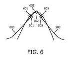
湾曲は、図6に示されるように、異なる曲線の異なる湾曲からの曲げ半径を比較することによって整合される。点501,502,503によって定義される(ステップ420から記憶された)曲線500の曲げ半径は、点601,602,603によって定義される(異なるソースからの)曲線600の曲げ半径と整合される。それらの曲げ半径が所定の誤差マージン内で一致する場合は、それらの湾曲は、一致すると決定される。点は不連続な距離で位置するので、新しい形状の曲線は、基準形状の点の間でシフトされてよい。様々な実施形態に従って、検出を改善するために、極めて小さいサンプルレートが使用されてよく、あるいは、補間がエルミート曲線又はスプラインとともに実行されてよい。The curves are matched by comparing the bend radii from different curves of the different curves, as shown in FIG. The bend radius of curve 500 (stored from step 420) defined by
レジストレーションプログラム134は、一致する湾曲をアライメントする(ステップ440)。平行移動及び回転は、一致する曲げ半径を有する異なるソースからの3次元湾曲を、記憶された永続性のある湾曲からの3次元湾曲とのアライメントに至らせるよう計算される。アライメントに必要とされる平行移動及び回転は、変換行列の形で表現されてよい。変換行列は、それをイメージングデータに適用するよう形状再構成に適用されてよい。行列は、一致する湾曲における点の座標から計算されてよい。
一実施形態に従って、レジストレーションプログラム134は、それぞれの屈曲の面にある三角形を形成するよう湾曲ごとに3つの点(曲げ点、近位点、及び遠位点)をとり、次いで三角形どうしをアライメントすることによって、湾曲どうしをアライメントする。 According to one embodiment,
一実施形態に従って、レジストレーションプログラム134は、レジストレーションと一致する処置前又は処置後の画像構成における新たにレジストレーションされた湾曲についての形状再構成を表示する(ステップ450)。 According to one embodiment,
本発明は、全体としてハードウェアの実施形態、又はハードウェア及びソフトウェアの両方の要素を含む実施形態の形をとることができる。例となる実施形態では、本発明は、ファームウェア、常駐ソフトウェア、マイクロコード、等を含むがそれらに限られないソフトウェアにおいて実施される。 The present invention may take the form of an entirely hardware embodiment or an embodiment containing both hardware and software elements. In an exemplary embodiment, the invention is implemented in software, which includes but is not limited to firmware, resident software, microcode, etc.
加えて、本発明は、コンピュータ又は何らかの命令実行システム若しくは装置によって又はそれらとともに使用されるプログラムコードを提供するコンピュータ利用可能な又はコンピュータ可読の記憶装置からアクセス可能なコンピュータプログラムの形をとってよい。この記載のために、コンピュータ利用可能な又はコンピュータ可読の記憶装置は、命令実行システム、機器、又は装置によって又はそれと共に使用されるプログラムを含む又は記憶することができるあらゆる機器であってよい。 Additionally, the present invention may take the form of a computer program accessible from a computer-usable or computer-readable storage device that provides program code for use by or in conjunction with a computer or any instruction execution system or device. For purposes of this description, a computer-usable or computer-readable storage device may be any device that can contain or store a program used by or in conjunction with an instruction execution system, device, or device.
前述の方法は、例えばコンピュータ等の機械によって実行される場合に、方法のステップを実行する非一時的なコンピュータ可読媒体においてエンコーダされた命令の機械実行可能なプログラムを有する機械可読記憶媒体を含むプログラム製品によって実現されてよい。このプログラムは、コンパクトディスク、フロッピー(登録商標)ディスク、USBメモリ装置、及び同様のものを含むがそれらに限られない様々な既知の機械可読記憶装置のいずれかに記憶されてよい。 The foregoing method, when executed by a machine such as a computer, for example, includes a machine-readable storage medium having a machine-executable program of instructions encoded in a non-transitory computer-readable medium that performs the steps of the method. It may be realized by a product. This program may be stored on any of a variety of known machine-readable storage devices including, but not limited to, compact disks, floppy disks, USB memory devices, and the like.
記憶装置は、電子、磁気、光、電磁気、赤外線、又は半導体システム(又は機器若しくは装置)であることができる。コンピュータ可読記憶装置の例には、半導体若しくはソリッドステートメモリ、磁気テープ、リムーバブルコンピュータディスケット、ランダムアクセスメモリ(RAM)、読出専用メモリ(ROM)、硬質磁気ディスク、及び光ディスクがある。光ディスクの目下の例には、コンピュータディスク−読出専用メモリ(CD−ROM)、コンパクトディスク−リード/ライト(CD−R/W)及びDVDがある。 The storage device can be electronic, magnetic, optical, electromagnetic, infrared, or semiconductor system (or apparatus or device). Examples of computer readable storage devices include semiconductor or solid state memory, magnetic tape, removable computer diskettes, random access memory (RAM), read only memory (ROM), hard magnetic disk, and optical disk. Current examples of optical disks include computer disk-read only memory (CD-ROM), compact disk-read / write (CD-R / W) and DVD.
前述の記載及び添付の図面は、本発明の制限ではなく実例であるよう意図される。本発明の適用範囲は、特許請求の範囲の及ぶ限り等価な変形及び構成を包含するよう意図される。 The foregoing description and accompanying drawings are intended to be illustrative rather than limiting on the present invention. The scope of the present invention is intended to cover equivalent modifications and constructions as long as they are covered by the appended claims.
開示されている実施形態に対する他の変形は、図面、本開示及び添付の特許請求の範囲の検討から、請求される発明を実施する際に当業者によって理解され達成され得る。特許請求の範囲において、語「有する(comprising)」は他の要素又はステップを除外せず、単称(冠詞a又はan)は複数個を除外しない。単一のプロセッサ又は他のユニットは、特許請求の範囲で挙げられている複数の項目の機能を満たしてよい。特定の特徴が相互に異なる請求項において挙げられているという単なる事実は、それらの特徴の組み合わせが有利に使用され得ないことを示すわけではない。特許請求の範囲における如何なる参照符号も、本発明の適用範囲を制限するよう解釈されるべきではない。
Other variations to the disclosed embodiments can be understood and accomplished by those skilled in the art in practicing the claimed invention, from a study of the drawings, this disclosure, and the appended claims. In the claims, the word “comprising” does not exclude other elements or steps, and the single name (article a or an) does not exclude a plurality. A single processor or other unit may fulfill the functions of several items recited in the claims. The mere fact that certain features are recited in mutually different claims does not indicate that a combination of these features cannot be used to advantage. Any reference signs in the claims should not be construed as limiting the scope of the present invention.
Claims (15)
Translated fromJapanese形状検知センサを備える光ファイバを組み込む少なくとも1つの器具と、
前記形状検知センサを用いて、前記器具の3次元形状を決定する光学コンソールと、
前記光ファイバの座標系をイメージングデータの座標系と位置合わせするプロセッサと
を有し、
前記プロセッサは、前記光ファイバにおいて永続性のある湾曲を識別し、前記光ファイバにおける前記永続性のある湾曲及び異なるソースにより取得されたデータにおける湾曲が一致するか否かを決定し、一致すると決定された湾曲を用いることによって、前記光ファイバの座標系を前記イメージングデータの座標系と位置合わせし、前記永続性のある湾曲は、前記器具の中に配置される又は前記器具に取り付けられる光ファイバの物理的制約から導出されるものである、システム。A system foraligning a coordinate system of a shape detection system with a coordinate system of imaging data before or during a treatment,
At least one instrument incorporating an optical fiber comprising a shape detection sensor;
An optical console for determining a three-dimensional shape of the instrumentusing the shape detection sensor;
A processor foraligning the coordinate system of the optical fiber with the coordinate system of the imaging data;
Wherein the processor identifies a curved a persistent in the optical fiber,to determine whether the curvaturematches thein persistence of certain curvatureandacquired Ri by the different sourcesdata in the opticalfiber, consistent by Rukotousing the determined curvature then, the coordinate system of the optical fiber isaligned withthe coordinate system of the imaging data,curvature of the persistence, attached to arranged the or the instrument in the instrument A systemthat is derived from the physical constraints of optical fiber .
請求項1に記載のシステム。The different sources are different imaging modalities;
The system of claim 1.
請求項2に記載のシステム。The curvature in the data acquired by the differentsourcesis the curvature in the image calculated from the imaging data before or during the treatment,
The system according to claim 2.
請求項3に記載のシステム。The processor is also a processor that processes imaging data before or during the procedure.
The system according to claim 3.
請求項3に記載のシステム。Thecurvature in differentacquired data by the source is thecurvature of the centerline of the segmentedthe instrumentin an imaging data in pre-treatment or treatment,
The system according to claim 3.
請求項1に記載のシステム。The curvature in the data acquired by the different sources isobtained by shape reconstruction at different pointsin time,
The system of claim 1.
請求項1に記載のシステム。Curvature in the data acquired by the different sources arecurved in the shape reconstruction ofoptical fiberswith different shape detectionsensor,
The system of claim 1.
プロセッサにおいて、
形状検知センサを備える光ファイバを備えた器具の再構成された画像において永続性のある湾曲を識別するステップであって、前記永続性のある湾曲は、前記器具の中に配置される又は前記器具に取り付けられる光ファイバの物理的制約から導出されるものである、ステップと、
前記永続性のある湾曲及び異なるソースにより取得されたデータにおける湾曲が一致するか否かを決定するステップと、
一致すると決定された湾曲を用いて前記位置合わせを行うステップと
を有する方法。A method ofaligning a coordinate system of a shape detection system with a coordinate system of imaging data before or during a treatment,
In the processor
Identifying a permanent curve in a reconstructed image of an instrument comprising anoptical fiber with a shape sensingsensor, wherein the permanent curve is located in the instrument or the instrument Derived from the physical constraints of the optical fiber attached to the
Determining whether the curvaturematchesthe curvatureandacquired Ri by the different sourcesdata of the persistence,
Performing the alignment using curvaturedetermined to match .
請求項8に記載の方法。Whether curvedto matchthe curvature and theacquired Ri by the differentdata sources of the persistence isdetermined by comparing the bending radius,
The method of claim 8.
請求項8に記載の方法。Whether curvedto matchthe curvature and theacquired Ri by the differentdata sources of the persistence isdetermined by comparing the slopeof their baysongs,
The method of claim 8.
前記形状検知センサを備える光ファイバを備えた器具の再構成された画像の湾曲における少なくとも1つの屈曲の半径を測定するステップと、
第1の時点で再構成された画像からの屈曲の半径を、前記形状検知センサを備える光ファイバを備えた器具についての第2の時点で再構成された画像と比較するステップであって、前記第1及び第2の時点は異なる、ステップと、
前記屈曲の半径が予め定義されたマッチング基準を満たすかどうかを決定するステップと、
前記マッチング基準が満たされる場合に前記屈曲の半径及び位置を記憶するステップと
を有する、請求項8に記載の方法。Identifying the permanent curvature comprises:
Measuring a radius of at least one bend in the curvature of the reconstructed image of an instrument comprising anoptical fiber comprising the shape detectionsensor ;
Comparing a radius of bending from a reconstructed image at afirst time point with a reconstructed image at asecond time point for an instrument comprising anoptical fiber comprising the shape sensingsensor, the stepcomprising: The first and second time points are different, steps ;
Determining whether the radius of bending meets a predefined matching criterion;
9. The method of claim 8, comprisingstoring the radius and position of the bend if the matching criteria are met.
請求項8に記載の方法。Curvature in the data acquired by the different sources arecurved in the shape reconstruction ofoptical fiberswith different shape detectionsensor,
The method of claim 8.
請求項8に記載の方法。The different sources are different imaging modalities;
The method of claim 8.
請求項13に記載の方法。The curvature in the data acquired by the differentsourcesis the curvature in the image calculated from the imaging data before or during the treatment,
The method of claim 13.
Applications Claiming Priority (3)
| Application Number | Priority Date | Filing Date | Title |
|---|---|---|---|
| US201261708206P | 2012-10-01 | 2012-10-01 | |
| US61/708,206 | 2012-10-01 | ||
| PCT/IB2013/058282WO2014053925A1 (en) | 2012-10-01 | 2013-09-04 | Three dimensional polyline registration using shape constraints |
Publications (2)
| Publication Number | Publication Date |
|---|---|
| JP2016502412A JP2016502412A (en) | 2016-01-28 |
| JP6246213B2true JP6246213B2 (en) | 2017-12-13 |
Family
ID=49726812
Family Applications (1)
| Application Number | Title | Priority Date | Filing Date |
|---|---|---|---|
| JP2015533720AActiveJP6246213B2 (en) | 2012-10-01 | 2013-09-04 | Alignment system, method and computer program |
Country Status (7)
| Country | Link |
|---|---|
| US (1) | US9430717B2 (en) |
| EP (1) | EP2903552B1 (en) |
| JP (1) | JP6246213B2 (en) |
| CN (1) | CN104703558B (en) |
| BR (1) | BR112015006948B1 (en) |
| RU (1) | RU2638445C2 (en) |
| WO (1) | WO2014053925A1 (en) |
Families Citing this family (43)
| Publication number | Priority date | Publication date | Assignee | Title |
|---|---|---|---|---|
| EP3025304B1 (en)* | 2013-07-23 | 2021-09-08 | Koninklijke Philips N.V. | Registration system for registering an imaging device with a tracking device |
| CN105934215B (en) | 2014-01-24 | 2019-11-26 | 皇家飞利浦有限公司 | The robot of imaging device with optic shape sensing controls |
| WO2016041793A1 (en) | 2014-09-16 | 2016-03-24 | Koninklijke Philips N.V. | Processing system arranged to cooperate with an optical-shape-sensing-enabled interventional device |
| EP3037056B1 (en) | 2014-12-23 | 2021-04-21 | Stryker European Holdings I, LLC | System for reconstructing a trajectory of an optical fiber |
| JP6584518B2 (en)* | 2015-02-20 | 2019-10-02 | コーニンクレッカ フィリップス エヌ ヴェKoninklijke Philips N.V. | Medical system, apparatus and method for shape detection |
| CN114795471A (en)* | 2015-04-06 | 2022-07-29 | 直观外科手术操作公司 | System and method for registration compensation in image-guided surgery |
| CN107660134B (en)* | 2015-05-22 | 2021-06-29 | 直观外科手术操作公司 | System and method for image-guided surgical recording |
| WO2017051279A1 (en)* | 2015-09-24 | 2017-03-30 | Koninklijke Philips N.V. | System and method to find improved views in transcatheter valve replacement with combined optical shape sensing and ultrasound image guidance |
| CN108135530B (en)* | 2015-10-02 | 2023-01-17 | 皇家飞利浦有限公司 | A hub for device navigation utilizing optical shape-sensing guidewires |
| US20180317554A1 (en) | 2015-10-30 | 2018-11-08 | British American Tobacco (Investments) Limited | Article for use with apparatus for heating smokable material |
| US20170119051A1 (en) | 2015-10-30 | 2017-05-04 | British American Tobacco (Investments) Limited | Article for Use with Apparatus for Heating Smokable Material |
| US11253168B2 (en) | 2015-11-26 | 2022-02-22 | Koninklijke Philips N.V. | Methods and systems for visualizing shapes of tracked devices |
| AU2017289114B2 (en) | 2016-06-29 | 2020-04-30 | Nicoventures Trading Limited | Apparatus for heating smokable material |
| US10132891B2 (en)* | 2016-09-16 | 2018-11-20 | General Electric Company | System and method for attenuation correction of a surface coil in a PET-MRI system |
| DE102016119579B4 (en)* | 2016-10-13 | 2023-08-17 | Fraunhofer-Gesellschaft zur Förderung der angewandten Forschung e.V. | Position determining device for determining a position of an instrument within a tubular structure |
| CN116211467A (en)* | 2016-12-05 | 2023-06-06 | 皇家飞利浦有限公司 | System and method for determining a length of a non-shape sensing interventional device using a shape sensing guidewire and determining a status of the guidewire relative to the interventional device |
| CN110087576B (en)* | 2017-01-09 | 2023-03-17 | 直观外科手术操作公司 | System and method for registering an elongated device to a three-dimensional image in an image-guided procedure |
| EP3606592B1 (en) | 2017-04-07 | 2025-01-08 | Bard Access Systems, Inc. | Optical fiber-based medical device tracking and monitoring system |
| CN111163692B (en)* | 2017-08-17 | 2023-08-15 | 纳维斯国际有限公司 | Reconstruction of anatomy from in vivo measurements |
| MY203861A (en) | 2017-09-15 | 2024-07-22 | Nicoventures Trading Ltd | Apparatus for heating smokable material |
| JPWO2019059031A1 (en)* | 2017-09-21 | 2020-12-24 | パナソニックIpマネジメント株式会社 | Process fiber and laser machining system using it |
| EP3545847A1 (en) | 2018-03-27 | 2019-10-02 | Koninklijke Philips N.V. | Assessing device for assessing an instrument's shape with respect to its registration suitability |
| DE102018108643A1 (en)* | 2018-04-11 | 2019-11-14 | Fraunhofer-Gesellschaft zur Förderung der angewandten Forschung e.V. | A position determining device for determining a position of an object within a tubular structure |
| EP4013338A4 (en) | 2019-08-12 | 2023-08-30 | Bard Access Systems, Inc. | SHAPE DETECTION SYSTEMS AND METHODS FOR MEDICAL DEVICES |
| CN112826497B (en) | 2019-11-25 | 2025-09-09 | 巴德阿克塞斯系统股份有限公司 | Optical tip tracking system and method thereof |
| EP4061272A4 (en) | 2019-11-25 | 2023-11-22 | Bard Access Systems, Inc. | Shape-sensing systems with filters and methods thereof |
| WO2021186330A1 (en)* | 2020-03-16 | 2021-09-23 | St. Jude Medical International Holding S.À.R.L. | System and method for optical sensor reference frame alignment |
| US20230240757A1 (en) | 2020-06-05 | 2023-08-03 | Koninklijke Philips N.V. | System for guiding interventional instrument to internal target |
| CN113842536A (en) | 2020-06-26 | 2021-12-28 | 巴德阿克塞斯系统股份有限公司 | Dislocation detection system |
| WO2022005870A1 (en) | 2020-06-29 | 2022-01-06 | Bard Access Systems, Inc. | Automatic dimensional frame reference for fiber optic |
| WO2022011287A1 (en) | 2020-07-10 | 2022-01-13 | Bard Access Systems, Inc. | Continuous fiber optic functionality monitoring and self-diagnostic reporting system |
| WO2022031613A1 (en) | 2020-08-03 | 2022-02-10 | Bard Access Systems, Inc. | Bragg grated fiber optic fluctuation sensing and monitoring system |
| CN114246583A (en) | 2020-09-25 | 2022-03-29 | 巴德阿克塞斯系统股份有限公司 | Fiber Optic Oximetry Systems for Detection and Confirmation |
| US12376911B2 (en) | 2020-09-30 | 2025-08-05 | Koninklijke Philips N.V. | Interventional medical device tracking |
| EP4221616A1 (en)* | 2020-09-30 | 2023-08-09 | Koninklijke Philips N.V. | Interventional medical device tracking |
| WO2022150411A1 (en) | 2021-01-06 | 2022-07-14 | Bard Access Systems, Inc. | Needle guidance using fiber optic shape sensing |
| US12426954B2 (en) | 2021-01-26 | 2025-09-30 | Bard Access Systems, Inc. | Fiber optic shape sensing system associated with port placement |
| CN113180824B (en)* | 2021-03-29 | 2023-06-20 | 杭州脉流科技有限公司 | Shaping needle form simulation method and device for microcatheter shaping, computer equipment and storage medium |
| CN115886783A (en)* | 2021-09-30 | 2023-04-04 | 巴德阿克塞斯系统股份有限公司 | Shape sensing reference frame |
| US12419694B2 (en) | 2021-10-25 | 2025-09-23 | Bard Access Systems, Inc. | Reference plane for medical device placement |
| US12343117B2 (en) | 2022-06-28 | 2025-07-01 | Bard Access Systems, Inc. | Fiber optic medical systems and methods for identifying blood vessels |
| US12349984B2 (en) | 2022-06-29 | 2025-07-08 | Bard Access Systems, Inc. | System, method, and apparatus for improved confirm of an anatomical position of a medical instrument |
| WO2025171214A2 (en)* | 2024-02-09 | 2025-08-14 | Intuitive Surgical Operations, Inc. | Directional filter and/or translational constraints for coordinate registration |
Family Cites Families (15)
| Publication number | Priority date | Publication date | Assignee | Title |
|---|---|---|---|---|
| US7747312B2 (en)* | 2000-01-04 | 2010-06-29 | George Mason Intellectual Properties, Inc. | System and method for automatic shape registration and instrument tracking |
| US7781724B2 (en)* | 2004-07-16 | 2010-08-24 | Luna Innovations Incorporated | Fiber optic position and shape sensing device and method relating thereto |
| WO2007135609A2 (en)* | 2006-05-24 | 2007-11-29 | Koninklijke Philips Electronics, N.V. | Coordinate system registration |
| US7804989B2 (en)* | 2006-10-30 | 2010-09-28 | Eigen, Inc. | Object recognition system for medical imaging |
| JP2008173397A (en)* | 2007-01-22 | 2008-07-31 | Olympus Corp | Endoscope system |
| JP5283157B2 (en)* | 2007-03-20 | 2013-09-04 | 国立大学法人静岡大学 | Surgery support information display device, surgery support information display method, and surgery support information display program |
| EP2626030A3 (en) | 2007-08-14 | 2017-03-08 | Koninklijke Philips N.V. | Robotic instrument systems and methods utilizing optical fiber sensors |
| US8077943B2 (en)* | 2008-03-10 | 2011-12-13 | General Electric Company | Method and apparatus for aligning a multi-modality imaging system |
| US20100056904A1 (en)* | 2008-09-02 | 2010-03-04 | Saunders John K | Image guided intervention |
| JP2013534433A (en)* | 2010-05-13 | 2013-09-05 | コーニンクレッカ フィリップス エヌ ヴェ | Optical fiber shape reconstruction |
| DE102010020781B4 (en)* | 2010-05-18 | 2019-03-28 | Siemens Healthcare Gmbh | Determination and verification of the coordinate transformation between an X-ray system and a surgical navigation system |
| JP5944395B2 (en)* | 2010-10-08 | 2016-07-05 | コーニンクレッカ フィリップス エヌ ヴェKoninklijke Philips N.V. | Flexible tether with integrated sensor for dynamic instrument tracking |
| WO2012101563A2 (en)* | 2011-01-27 | 2012-08-02 | Koninklijke Philips Electronics N.V. | Integration of fiber optic shape sensing within an nterventional environment |
| US9675304B2 (en) | 2011-06-27 | 2017-06-13 | Koninklijke Philips N.V. | Live 3D angiogram using registration of a surgical tool curve to an X-ray image |
| JP6114748B2 (en) | 2011-08-16 | 2017-04-12 | コーニンクレッカ フィリップス エヌ ヴェKoninklijke Philips N.V. | Curved multiplanar reconstruction using optical fiber shape data |
- 2013
- 2013-09-04EPEP13802423.7Apatent/EP2903552B1/enactiveActive
- 2013-09-04BRBR112015006948-7Apatent/BR112015006948B1/ennot_activeIP Right Cessation
- 2013-09-04JPJP2015533720Apatent/JP6246213B2/enactiveActive
- 2013-09-04USUS14/428,743patent/US9430717B2/enactiveActive
- 2013-09-04CNCN201380051568.XApatent/CN104703558B/enactiveActive
- 2013-09-04RURU2015116615Apatent/RU2638445C2/enactive
- 2013-09-04WOPCT/IB2013/058282patent/WO2014053925A1/enactiveApplication Filing
Also Published As
| Publication number | Publication date |
|---|---|
| RU2015116615A (en) | 2016-11-27 |
| US20150254526A1 (en) | 2015-09-10 |
| US9430717B2 (en) | 2016-08-30 |
| JP2016502412A (en) | 2016-01-28 |
| CN104703558A (en) | 2015-06-10 |
| BR112015006948A2 (en) | 2017-07-04 |
| EP2903552B1 (en) | 2017-07-05 |
| BR112015006948B1 (en) | 2021-06-29 |
| CN104703558B (en) | 2017-10-24 |
| WO2014053925A1 (en) | 2014-04-10 |
| EP2903552A1 (en) | 2015-08-12 |
| RU2638445C2 (en) | 2017-12-13 |
Similar Documents
| Publication | Publication Date | Title |
|---|---|---|
| JP6246213B2 (en) | Alignment system, method and computer program | |
| US20250152254A1 (en) | Device tracking using longitudinal encoding | |
| JP6822955B2 (en) | Automatic tracking and alignment of ultrasonic probes using optical shape detection without tip fixation | |
| CN104349715B (en) | Distributed sensing device for reference to physiological characteristics | |
| EP2830502B1 (en) | Artifact removal using shape sensing | |
| JP6129750B2 (en) | Non-rigid morphing of blood vessel images using the shape of the device in the blood vessel | |
| US11064955B2 (en) | Shape sensing assisted medical procedure | |
| CN105491952B (en) | Probe positioning | |
| JP2017537698A5 (en) | ||
| US20140155737A1 (en) | Curved multi-planar reconstruction using fiber optic shape data | |
| JP7292205B2 (en) | Systems and methods for determining the length of a non-shape sensing interventional device using a shape sensing guidewire and determining the condition of the guidewire relative to the interventional device | |
| US20200163584A1 (en) | Non-rigid-body morphing of vessel image using intravascular device shape | |
| US20160178357A1 (en) | System and Method for Reconstructing a Trajectory of an Optical Fiber | |
| JP6835959B2 (en) | Positioning device for locating instruments within a tubular structure | |
| WO2016207163A1 (en) | System and method for registering a structure using fiber-optical realshape data | |
| WO2015092590A1 (en) | System and method for determining the entry point to the body using optical shape sensing |
Legal Events
| Date | Code | Title | Description |
|---|---|---|---|
| A521 | Request for written amendment filed | Free format text:JAPANESE INTERMEDIATE CODE: A523 Effective date:20150402 | |
| A621 | Written request for application examination | Free format text:JAPANESE INTERMEDIATE CODE: A621 Effective date:20160901 | |
| A977 | Report on retrieval | Free format text:JAPANESE INTERMEDIATE CODE: A971007 Effective date:20170608 | |
| A131 | Notification of reasons for refusal | Free format text:JAPANESE INTERMEDIATE CODE: A131 Effective date:20170711 | |
| A521 | Request for written amendment filed | Free format text:JAPANESE INTERMEDIATE CODE: A523 Effective date:20171002 | |
| TRDD | Decision of grant or rejection written | ||
| A01 | Written decision to grant a patent or to grant a registration (utility model) | Free format text:JAPANESE INTERMEDIATE CODE: A01 Effective date:20171017 | |
| A61 | First payment of annual fees (during grant procedure) | Free format text:JAPANESE INTERMEDIATE CODE: A61 Effective date:20171114 | |
| R150 | Certificate of patent or registration of utility model | Ref document number:6246213 Country of ref document:JP Free format text:JAPANESE INTERMEDIATE CODE: R150 | |
| R250 | Receipt of annual fees | Free format text:JAPANESE INTERMEDIATE CODE: R250 | |
| R250 | Receipt of annual fees | Free format text:JAPANESE INTERMEDIATE CODE: R250 | |
| R250 | Receipt of annual fees | Free format text:JAPANESE INTERMEDIATE CODE: R250 | |
| R250 | Receipt of annual fees | Free format text:JAPANESE INTERMEDIATE CODE: R250 | |
| R250 | Receipt of annual fees | Free format text:JAPANESE INTERMEDIATE CODE: R250 |