JP6244863B2 - Crew protection device - Google Patents
Crew protection deviceDownload PDFInfo
- Publication number
- JP6244863B2 JP6244863B2JP2013252735AJP2013252735AJP6244863B2JP 6244863 B2JP6244863 B2JP 6244863B2JP 2013252735 AJP2013252735 AJP 2013252735AJP 2013252735 AJP2013252735 AJP 2013252735AJP 6244863 B2JP6244863 B2JP 6244863B2
- Authority
- JP
- Japan
- Prior art keywords
- vehicle
- roll bar
- seat
- bent
- protection device
- Prior art date
- Legal status (The legal status is an assumption and is not a legal conclusion. Google has not performed a legal analysis and makes no representation as to the accuracy of the status listed.)
- Active
Links
Images


Landscapes
- Seats For Vehicles (AREA)
- Body Structure For Vehicles (AREA)
Description
Translated fromJapanese本発明は、乗員保護装置に関する。 The present invention relates to an occupant protection device.
従来から、車両の横転時などに乗員を保護するロールバーを備えた車両が公知である。このロールバーのなかには、乗員の居住スペースを効率的に確保するために、車両上下方向の途中部分に屈曲部を有するものがある。このため、車両の横転時などに荷重がロールバーに入力された場合には、入力荷重がロールバーの屈曲部に集中し、ロールバーが折れ変形し易くなるおそれがある。 Conventionally, a vehicle including a roll bar that protects an occupant when the vehicle rolls over is known. Some of these roll bars have a bent portion in the middle of the vehicle in the vertical direction in order to efficiently secure a passenger's living space. For this reason, when a load is input to the roll bar when the vehicle rolls over, the input load may be concentrated on the bent portion of the roll bar, and the roll bar may be easily bent and deformed.
従って、特許文献1では、ロールバーにおいてメインのフレーム部分に別のフレーム部分を組み付けることで、ロールバー全体の強度を向上させている。 Therefore, in patent document 1, the intensity | strength of the whole roll bar is improved by attaching another flame | frame part to the main flame | frame part in a roll bar.
しかし、前記特許文献1記載のロールバーでは、別のフレーム部分を追加することによりロールバーの占有スペースが大きくなるため、乗員の居住スペースが減少してしまうという問題があった。 However, the roll bar described in Patent Document 1 has a problem that the space occupied by the occupant decreases because the space occupied by the roll bar increases by adding another frame portion.
そこで、本発明は、乗員の居住スペースの大きさを維持しつつ、荷重入力時におけるロールバーの折れ変形を抑制することができる乗員保護装置を提供することを目的とする。 Then, an object of this invention is to provide the passenger | crew protection apparatus which can suppress the bending deformation of a roll bar at the time of load input, maintaining the magnitude | size of a passenger | crew's living space.
本発明に係る乗員保護装置においては、座席の背面側にロールバーを設けている。ロールバーのベース部は、車両上方に向かうに従って車両前後方向のいずれか一方側に屈曲する第一屈曲部と、第一屈曲部から車両上方に向けて延在すると共に、車両上方に行くに従って前記一方側へ傾斜して延びる傾斜部と、を有する。さらに、ベース部は、傾斜部の上部に形成され、車両上方に向かうに従って車両前後方向の他方側に屈曲する第二屈曲部を有する。傾斜部よりも前記一方側に、車体フロアと間隔を隔てて対向してロールバーが第一屈曲部を基点に前記一方側へ折れ曲がるように変形したときに車体フロアに突き当たる荷重受け部を有する補助ブラケットがベース部に配設されている。In the occupant protection device according to the present invention, a roll bar is provided on the back side of the seat. The base portion of the roll bar is bent to one side of the vehicle front-rear direction as it goes upwards of the vehicle, and extends from the first bent portion toward the upper side of the vehicle. And an inclined portion extending inclined to one side. Furthermore, the base portion has a second bent portion that is formed on the upper portion of the inclined portion and bends to the other side in the vehicle front-rear direction as it goes upward of the vehicle. On the one side than the inclined portion,a roll bar load receiving portion thatabutting on the vehicle body floor when deformed as bends to the one side of the first bent portion to the base to face at a vehicle floor and spacing An auxiliary bracket having the above is disposed on the base portion.
本発明に係る乗員保護装置によれば、乗員の居住スペースの大きさを維持しつつ、荷重入力時におけるロールバーの折れ変形を抑制することができるという効果を有する。 The occupant protection device according to the present invention has an effect that the roll bar can be prevented from being deformed at the time of load input while maintaining the size of the occupant's living space.
以下、本発明の実施形態を図面と共に詳述する。なお、図面において、矢印FRは車両前方を示し、矢印UPRは車両上方を示す。 Hereinafter, embodiments of the present invention will be described in detail with reference to the drawings. In the drawings, the arrow FR indicates the front of the vehicle, and the arrow UPR indicates the upper side of the vehicle.
図1に示すように、車体上部の左右側部には、車両前後方向に沿って延在するルーフサイドレール1,1が一対に配設されている。このルーフサイドレール1は、剛性を有する車体骨格部材であり、車両上下方向に延びるピラー2の上端部がルーフサイドレール1に接合されている。また、左右のルーフサイドレール1,1間には、車体上部のルーフ部を構成するルーフパネル3が配設されている。具体的には、ルーフサイドレール1は、ルーフサイドレールインナ1aとルーフサイドレールアウタ1bとから閉断面構造に構成されている。ピラー2は、ピラーインナ2aとピラーアウタ2bとから閉断面構造に構成されている。ルーフパネル3には、車両前後方向に沿って延びるビード3aが複数設けられている。 As shown in FIG. 1, a pair of roof side rails 1, 1 extending along the vehicle front-rear direction are disposed on the left and right sides of the upper part of the vehicle body. The roof side rail 1 is a rigid vehicle body skeleton member, and an upper end portion of a
車体下部のフロア部には、車室とエンジンルームとを区画するバルクヘッド4(図6参照)が配設されている。このバルクヘッド4の上面4aに、運転席5および助手席(図示せず)が配設されており、バルクヘッド4と運転席5および助手席との間には、カーペット6が介在されている。このカーペット6は、比較的軟質な表面層と、比較的高い弾力性がある中間層と、比較的硬質な裏面層との三層から構成されている。 A bulkhead 4 (see FIG. 6) for partitioning the vehicle compartment and the engine room is disposed on the floor portion at the bottom of the vehicle body. A driver's seat 5 and a passenger seat (not shown) are disposed on the
運転席5は、シートの座面を形成するシートクッション5aと、シートクッション5aの車両後端部に連結され、シートの背もたれを形成するシートバック5bとから主に構成されている。このシートバック5bの上部には、乗員の頭部を支持するヘッドレスト5cが一体に設けられている。なお、ヘッドレスト5cはシートバック5bとは別体に設けられていてもよく、ヘッドレスト5cがシートバック5bに設けられていなくてもよい。 The driver's seat 5 mainly includes a
そして、運転席5の背面側(本実施形態では、車両後方)には、車両の横転時などに乗員を保護するロールバー7が配設されている。このロールバー7は、車体フロアの一部であるバルクヘッド4に固定されるベース部8と、ベース部8から運転席5のシートバック5bの上端近傍の高さまで車両上方に向けて延設される本体部9とを有する。本実施形態では、ロールバー7とルーフサイドレール1とは、連結ブラケット10により連結されている。この連結ブラケット10は、ロールバー7の本体部9に装着されるロールバー側ブラケット10aと、ルーフサイドレール1のルーフサイドレールインナ1aに装着されるルーフサイドレール側ブラケット10bとから構成されている。また、ルーフサイドレール1におけるルーフサイドレール側ブラケット10bが装着される箇所には、ルーフサイドレールインナ1aとルーフサイドレールアウタ1bとの間にZ型ブラケット11が介在されている。 A
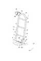
図2から図5に示すように、ロールバー7は、車幅方向に間隔を隔てて一対に配設され、車両上下方向に延びる縦パイプ12,13と、車両上方に凸となるように湾曲させて形成され、左右の縦パイプ12,13の上端同士を連結する湾曲パイプ14とを有する。また、ロールバー7は、車両上下方向に間隔を隔てて配設され、車幅方向に延びて左右の縦パイプ12,13同士を連結する複数(本実施形態では、3本)の横パイプ15を有する。さらに、ロールバー7の上部(本体部9)に、左右の縦パイプ12,13と横パイプ15との間を上側プレート16が架け渡されている。ロールバー7の下部(ベース部8)には、左右の縦パイプ12,13と横パイプ15との間を下側プレート17が架け渡されている。 As shown in FIG. 2 to FIG. 5, the
本実施形態では、ロールバー7における車幅方向内側の縦パイプ12の下端部は、下側プレート17とバルクヘッド4の背面4bとの間に挟まれており、車幅方向外側の縦パイプ13の下端部は、バルクヘッド4の上面4aと間隔C1を隔てて対向している。また、上側プレート16および下側プレート17は、溶接によって左右の縦パイプ12,13および横パイプ15と接合されている。このようなロールバー7が、下側プレート17によって、ボルト18やナット19など(図6参照)を用いてバルクヘッド4の背面4bに取り付けられている。 In the present embodiment, the lower end of the
図6に示すように、ロールバー7のベース部8は、車両上方に向かうに従って車両前方側に屈曲する第一屈曲部20と、第一屈曲部20から車両上方に向けて延在すると共に、車両上方に行くに従って車両前方側へ傾斜して延びる傾斜部21とを有する。また、ロールバー7のベース部8は、傾斜部21の上部に形成され、車両上方に向かうに従って車両後方側に屈曲する第二屈曲部22を有する。本実施形態では、ロールバー7における車幅方向内側の縦パイプ12の下端部を平板状に潰すことにより、平板状に潰した部分の車両上方側に第一屈曲部20および傾斜部21を形成している。つまり、ベース部8の第一屈曲部20は、車幅方向内側の縦パイプ12における車両前方側の表面を車両後方側に向けて凹ませた形状とされている。なお、図6において、符号CLは車幅方向内側の縦パイプ12の中心線を示す。 As shown in FIG. 6, the
さらに、傾斜部21よりも車両前方側に、バルクヘッド4の上面4aと間隔C2を隔てて対向する荷重受け部23を有する補助ブラケット24がロールバー7のベース部8に配設されている。荷重受け部23とバルクヘッド4の上面4aとの間隔C2は、車幅方向外側の縦パイプ13の下端部とバルクヘッド4の上面4aとの間隔C1よりも小さく、例えば10mm程度とされる。具体的には、補助ブラケット24は、車幅方向内側の縦パイプ12および下側プレート17に固定される固定部25と、固定部25から車両下方に向けて延出する延出部26と、延出部26の下端に形成される荷重受け部23とを有する。固定部25は、第一屈曲部20および第二屈曲部22の変形を拘束しないようにするために、第二屈曲部22よりも車両上方側において車幅方向内側の縦パイプ12および下側プレート17に固定されている。延出部26は、外部に露出しないように第一屈曲部20、傾斜部21および第二屈曲部22を車両前方側から覆うカバー部27を有する。荷重受け部23は、平板状に形成されており、バルクヘッド4の上面4aと対向する平面23aを有する。 Further, an
以下に、本実施形態による作用効果を説明する。 Below, the effect by this embodiment is demonstrated.
(1)本実施形態による乗員保護装置は、座席(本実施形態では、運転席5)の背面側に配設されるロールバー7を備えている。ロールバー7は、車体フロアに固定されるベース部8と、ベース部8から運転席5のシートバック5bの上端近傍の高さまで車両上方に向けて延設される本体部9とを有する。ベース部8は、車両上方に向かうに従って車両前後方向のいずれか一方側(本実施形態では、車両前方側)に屈曲する第一屈曲部20と、第一屈曲部20から車両上方に向けて延在すると共に、車両上方に行くに従って前記一方側へ傾斜して延びる傾斜部21とを有する。また、ロールバー7のベース部8は、傾斜部21の上部に形成され、車両上方に向かうに従って車両前後方向の他方側(車両後方側)に屈曲する第二屈曲部22を有する。さらに、前記傾斜部21よりも前記一方側に、前記車体フロアと間隔を隔てて対向する荷重受け部23を有する補助ブラケット24がロールバー7のベース部8に配設されている。 (1) The occupant protection device according to the present embodiment includes a
車両の横転などによりルーフサイドレール1またはピラー2から連結ブラケット10を介してロールバー7に入力された荷重は、図5に示されるように、主に、ロールバー7の車幅方向内側の下端部(図5中のB部)に伝達される。そして、このロールバー7の車幅方向内側の下端部からバルクヘッド4へ入力荷重が伝達される。 The load input to the
ここで、ロールバー7のベース部8は、車両前方側へ屈曲形成された第一屈曲部20と、第一屈曲部20よりも車両上方であって、車両後方側へ屈曲形成された第二屈曲部22とを有する。さらに、ベース部8は、第一屈曲部20と第二屈曲部22との間に形成され、車両上方に行くに従って車両前方側へ傾斜して延びる傾斜部21を有する。このため、ロールバー7への荷重入力時には、図6中の矢印Cで示されるように、ロールバー7が第一屈曲部20および第二屈曲部22を基点に車両前方側へ折れ変形するようにコントロールすることができる。 Here, the
ロールバー7が第一屈曲部20を基点に車両前方側へ折れ変形すると、ベース部8に配設した補助ブラケット24の荷重受け部23がカーペット6を介して車体フロアの一部であるバルクヘッド4に突き当たる。このため、荷重受け部23がバルクヘッド4に突き当たったとき以降は、入力荷重は主に荷重受け部23からバルクヘッド4へ伝達される。 When the
図7に示されるように、ロールバー7の反力は初期(時刻T0〜T1)が大きく、荷重受け部23がバルクヘッド4に突き当たったとき(時刻T1)以降は反力が小さくなっていく。一方、荷重受け部23が設けられる補助ブラケット24の反力は初期(時刻T0〜T1)がゼロであり、荷重受け部23がバルクヘッド4に突き当たったとき(時刻T1)以降は反力がある程度まで大きくなっていく。なお、カーペット6の反力は荷重受け部23の当接初期(時刻T1〜T2)には低いが、時刻T2以降は荷重受け部23がカーペット6の各層を押しつぶしていく段階で反力が徐々に大きくなっていく。 As shown in FIG. 7, the reaction force of the
従って、ロールバー7への入力荷重の集中が緩和され、ロールバー7の反力のピークを低減することができる。また、ロールバー7の本体部9が、第一屈曲部20および第二屈曲部22以外に屈曲部を有しているとしても、この屈曲部への入力荷重の集中も緩和することができる。このため、ロールバー7を破断させることなく荷重入力のエネルギーを吸収することができ、効率的なエネルギー吸収が可能になる。従って、荷重入力時におけるロールバー7の折れ変形を抑制することができる。 Therefore, the concentration of the input load on the
ここで、ロールバー7のベース部8に配設される補助ブラケット24は、ロールバー7全体の強度を向上させることを目的とするものではないため、サイズが比較的小さくても足りる。このため、補助ブラケット24をロールバー7に追加したとしても、ロールバー7の占有スペースはさほど大きくはならない。従って、乗員の居住スペースの大きさを維持することができる。 Here, since the
以上より、本実施形態によれば、乗員の居住スペースの大きさを維持しつつ、荷重入力時におけるロールバー7の折れ変形を抑制することができる。 As described above, according to the present embodiment, it is possible to suppress the bending deformation of the
(2)前記ベース部8の第一屈曲部20は、前記一方側(車両前方側)の表面を他方側(車両後方側)に向けて凹ませた形状とされていてもよい。 (2) The
ベース部8の第一屈曲部20における車両前方側の表面を車両後方側に向けて凹ませておくことで、ロールバー7への荷重入力時に、この凹ませた部位(第一屈曲部20)にてロールバー7が局所変形するようにコントロールすることができる。これにより、ロールバー7によって荷重入力初期のエネルギーを吸収することができ、より効率的なエネルギー吸収が可能になる。 By concave the front surface of the first
(3)前記荷重受け部23は、平板状に形成されており、前記車体フロアと対向する平面23aを有していてもよい。 (3) The
荷重受け部23に車体フロアの一部であるバルクヘッド4と対向する平面23aを形成しておくことで、ロールバー7への荷重入力時において荷重受け部23がバルクヘッド4に突き当たった際に、入力荷重が荷重受け部23からバルクヘッド4へ伝達され易くなる。これにより、補助ブラケット24によって効率的にエネルギーを吸収することができ、より効率的なエネルギー吸収が可能になる。 By forming a
ところで、本発明の乗員保護装置は前述の実施形態に例をとって説明したが、この実施形態に限ることなく本発明の要旨を逸脱しない範囲で他の実施形態を各種採用することができる。 The occupant protection device of the present invention has been described by taking the above embodiment as an example. However, the present invention is not limited to this embodiment, and various other embodiments can be adopted without departing from the gist of the present invention.
例えば、ロールバーを助手席の背面側に配設してもよく、運転席および助手席以外の座席の背面側に配設してもよい。また、「車両前後方向のいずれか一方側」を車両後方側として、ロールバーのベース部に形成する第一屈曲部および第二屈曲部の屈曲方向、傾斜部の傾斜方向などを前述の実施形態とは逆向きにしてもよい。 For example, the roll bar may be disposed on the back side of the passenger seat, or may be disposed on the back side of a seat other than the driver seat and the passenger seat. In addition, the above-described embodiment includes the bending direction of the first bent portion and the second bent portion formed in the base portion of the roll bar, the inclined direction of the inclined portion, etc., with “one side of the vehicle longitudinal direction” as the vehicle rear side. May be reversed.
4 バルクヘッド(車体フロア)
5 運転席(座席)
5a シートクッション
5b シートバック
7 ロールバー
8 ベース部
9 本体部
20 第一屈曲部
21 傾斜部
22 第二屈曲部
23 荷重受け部
23a 平面
24 補助ブラケット4 Bulkhead (body floor)
5 Driver's seat
Claims (4)
Translated fromJapanese前記ベース部は、車両上方に向かうに従って車両前後方向のいずれか一方側に屈曲する第一屈曲部と、前記第一屈曲部から車両上方に向けて延在すると共に、車両上方に行くに従って前記一方側へ傾斜して延びる傾斜部と、前記傾斜部の上部に形成され、車両上方に向かうに従って車両前後方向の他方側に屈曲する第二屈曲部と、を有し、
前記傾斜部よりも前記一方側に、前記車体フロアと間隔を隔てて対向して前記ロールバーが前記第一屈曲部を基点に前記一方側へ折れ曲がるように変形したときに前記車体フロアに突き当たる荷重受け部を有する補助ブラケットが前記ベース部に配設されていることを特徴とする乗員保護装置。A seat having a seat cushion and a seat back; and a roll bar disposed on the back side of the seat, wherein the roll bar is fixed to a vehicle body floor, and the seat of the seat from the base portion. In the occupant protection device having a main body extending toward the vehicle upper side to a height near the upper end of the back,
The base portion is bent to one side in the vehicle front-rear direction as it goes upward of the vehicle, and extends from the first bent portion toward the vehicle upper side, and the one side as it goes upward of the vehicle. An inclined portion extending inclined to the side, and a second bent portion that is formed on the upper portion of the inclined portion and bends to the other side in the vehicle front-rear direction as it goes upward of the vehicle,
Theroll bar abuts against the vehicle body floor when the roll bar is deformed so as to bend toward the one side with the first bent portion as a base point, facing the vehicle body floor at a distance from the inclined portion. occupant protection system support brackets havingother Ru load receiving portion is characterized in that it is arranged on the base portion.
Priority Applications (1)
| Application Number | Priority Date | Filing Date | Title |
|---|---|---|---|
| JP2013252735AJP6244863B2 (en) | 2013-12-06 | 2013-12-06 | Crew protection device |
Applications Claiming Priority (1)
| Application Number | Priority Date | Filing Date | Title |
|---|---|---|---|
| JP2013252735AJP6244863B2 (en) | 2013-12-06 | 2013-12-06 | Crew protection device |
Publications (2)
| Publication Number | Publication Date |
|---|---|
| JP2015110354A JP2015110354A (en) | 2015-06-18 |
| JP6244863B2true JP6244863B2 (en) | 2017-12-13 |
Family
ID=53525638
Family Applications (1)
| Application Number | Title | Priority Date | Filing Date |
|---|---|---|---|
| JP2013252735AActiveJP6244863B2 (en) | 2013-12-06 | 2013-12-06 | Crew protection device |
Country Status (1)
| Country | Link |
|---|---|
| JP (1) | JP6244863B2 (en) |
Family Cites Families (3)
| Publication number | Priority date | Publication date | Assignee | Title |
|---|---|---|---|---|
| JP5254080B2 (en)* | 2009-03-02 | 2013-08-07 | 本田技研工業株式会社 | Body structure |
| JP5444868B2 (en)* | 2009-06-18 | 2014-03-19 | マツダ株式会社 | Lower body structure of the vehicle |
| JP5573242B2 (en)* | 2010-03-05 | 2014-08-20 | マツダ株式会社 | Rear structure of vehicle with airbag device |
- 2013
- 2013-12-06JPJP2013252735Apatent/JP6244863B2/enactiveActive
Also Published As
| Publication number | Publication date |
|---|---|
| JP2015110354A (en) | 2015-06-18 |
Similar Documents
| Publication | Publication Date | Title |
|---|---|---|
| JP5799838B2 (en) | Vehicle seat cushion frame | |
| JP6387258B2 (en) | Seat back frame and vehicle seat | |
| JP6557046B2 (en) | Car body rear structure | |
| JPWO2013187112A1 (en) | Car body rear structure | |
| CN105189197B (en) | Car seat and seat frame thereof | |
| JP5728524B2 (en) | Body structure | |
| JP2012076600A (en) | Vehicle floor framework structure | |
| JP6953481B2 (en) | Cross member structure of the car body | |
| JP2014034226A (en) | Vehicle seat | |
| JP6094380B2 (en) | Mounting structure for vehicle seat | |
| JP2016097783A (en) | Protective structure of power storage device | |
| JP5584879B2 (en) | Rear body structure of automobile | |
| JP2016078658A (en) | Lower body structure of the vehicle | |
| JP2018192948A (en) | Vehicle body understructure | |
| JP6234992B2 (en) | Automotive chassis optimized to absorb front shock | |
| JP2013199203A (en) | Impact absorption structure of vehicle | |
| JP2016052820A (en) | Rear seat back frame structure | |
| JP6244863B2 (en) | Crew protection device | |
| JP6384257B2 (en) | Vehicle floor structure | |
| JP4637249B2 (en) | Vehicle seat | |
| JP6244853B2 (en) | Floor structure at the rear of the vehicle | |
| JP5548022B2 (en) | Side collision prevention structure for vehicle seats | |
| JP2009248737A (en) | Glove box | |
| JP5324288B2 (en) | Reclining seat | |
| JP6303983B2 (en) | Vehicle seat structure |
Legal Events
| Date | Code | Title | Description |
|---|---|---|---|
| A621 | Written request for application examination | Free format text:JAPANESE INTERMEDIATE CODE: A621 Effective date:20160926 | |
| A131 | Notification of reasons for refusal | Free format text:JAPANESE INTERMEDIATE CODE: A131 Effective date:20170627 | |
| A977 | Report on retrieval | Free format text:JAPANESE INTERMEDIATE CODE: A971007 Effective date:20170629 | |
| A521 | Written amendment | Free format text:JAPANESE INTERMEDIATE CODE: A523 Effective date:20170728 | |
| TRDD | Decision of grant or rejection written | ||
| A01 | Written decision to grant a patent or to grant a registration (utility model) | Free format text:JAPANESE INTERMEDIATE CODE: A01 Effective date:20171017 | |
| A61 | First payment of annual fees (during grant procedure) | Free format text:JAPANESE INTERMEDIATE CODE: A61 Effective date:20171030 | |
| R151 | Written notification of patent or utility model registration | Ref document number:6244863 Country of ref document:JP Free format text:JAPANESE INTERMEDIATE CODE: R151 |