JP6238624B2 - Image forming apparatus - Google Patents
Image forming apparatusDownload PDFInfo
- Publication number
- JP6238624B2 JP6238624B2JP2013159297AJP2013159297AJP6238624B2JP 6238624 B2JP6238624 B2JP 6238624B2JP 2013159297 AJP2013159297 AJP 2013159297AJP 2013159297 AJP2013159297 AJP 2013159297AJP 6238624 B2JP6238624 B2JP 6238624B2
- Authority
- JP
- Japan
- Prior art keywords
- unit
- toner
- image forming
- forming apparatus
- container
- Prior art date
- Legal status (The legal status is an assumption and is not a legal conclusion. Google has not performed a legal analysis and makes no representation as to the accuracy of the status listed.)
- Active
Links
Images


Classifications
- G—PHYSICS
- G03—PHOTOGRAPHY; CINEMATOGRAPHY; ANALOGOUS TECHNIQUES USING WAVES OTHER THAN OPTICAL WAVES; ELECTROGRAPHY; HOLOGRAPHY
- G03G—ELECTROGRAPHY; ELECTROPHOTOGRAPHY; MAGNETOGRAPHY
- G03G21/00—Arrangements not provided for by groups G03G13/00 - G03G19/00, e.g. cleaning, elimination of residual charge
- G03G21/16—Mechanical means for facilitating the maintenance of the apparatus, e.g. modular arrangements
- G03G21/1642—Mechanical means for facilitating the maintenance of the apparatus, e.g. modular arrangements for connecting the different parts of the apparatus
- G03G21/1647—Mechanical connection means
- G—PHYSICS
- G03—PHOTOGRAPHY; CINEMATOGRAPHY; ANALOGOUS TECHNIQUES USING WAVES OTHER THAN OPTICAL WAVES; ELECTROGRAPHY; HOLOGRAPHY
- G03G—ELECTROGRAPHY; ELECTROPHOTOGRAPHY; MAGNETOGRAPHY
- G03G15/00—Apparatus for electrographic processes using a charge pattern
- G03G15/06—Apparatus for electrographic processes using a charge pattern for developing
- G03G15/08—Apparatus for electrographic processes using a charge pattern for developing using a solid developer, e.g. powder developer
- G03G15/0822—Arrangements for preparing, mixing, supplying or dispensing developer
- G03G15/0865—Arrangements for supplying new developer
- G03G15/0867—Arrangements for supplying new developer cylindrical developer cartridges, e.g. toner bottles for the developer replenishing opening
- G03G15/0868—Toner cartridges fulfilling a continuous function within the electrographic apparatus during the use of the supplied developer material, e.g. toner discharge on demand, storing residual toner, acting as an active closure for the developer replenishing opening
- G—PHYSICS
- G03—PHOTOGRAPHY; CINEMATOGRAPHY; ANALOGOUS TECHNIQUES USING WAVES OTHER THAN OPTICAL WAVES; ELECTROGRAPHY; HOLOGRAPHY
- G03G—ELECTROGRAPHY; ELECTROPHOTOGRAPHY; MAGNETOGRAPHY
- G03G15/00—Apparatus for electrographic processes using a charge pattern
- G03G15/06—Apparatus for electrographic processes using a charge pattern for developing
- G03G15/08—Apparatus for electrographic processes using a charge pattern for developing using a solid developer, e.g. powder developer
- G03G15/0822—Arrangements for preparing, mixing, supplying or dispensing developer
- G03G15/0865—Arrangements for supplying new developer
- G03G15/0867—Arrangements for supplying new developer cylindrical developer cartridges, e.g. toner bottles for the developer replenishing opening
- G03G15/087—Developer cartridges having a longitudinal rotational axis, around which at least one part is rotated when mounting or using the cartridge
- G03G15/0872—Developer cartridges having a longitudinal rotational axis, around which at least one part is rotated when mounting or using the cartridge the developer cartridges being generally horizontally mounted parallel to its longitudinal rotational axis
- G—PHYSICS
- G03—PHOTOGRAPHY; CINEMATOGRAPHY; ANALOGOUS TECHNIQUES USING WAVES OTHER THAN OPTICAL WAVES; ELECTROGRAPHY; HOLOGRAPHY
- G03G—ELECTROGRAPHY; ELECTROPHOTOGRAPHY; MAGNETOGRAPHY
- G03G15/00—Apparatus for electrographic processes using a charge pattern
- G03G15/06—Apparatus for electrographic processes using a charge pattern for developing
- G03G15/08—Apparatus for electrographic processes using a charge pattern for developing using a solid developer, e.g. powder developer
- G03G15/0822—Arrangements for preparing, mixing, supplying or dispensing developer
- G03G15/0877—Arrangements for metering and dispensing developer from a developer cartridge into the development unit
- G—PHYSICS
- G03—PHOTOGRAPHY; CINEMATOGRAPHY; ANALOGOUS TECHNIQUES USING WAVES OTHER THAN OPTICAL WAVES; ELECTROGRAPHY; HOLOGRAPHY
- G03G—ELECTROGRAPHY; ELECTROPHOTOGRAPHY; MAGNETOGRAPHY
- G03G2215/00—Apparatus for electrophotographic processes
- G03G2215/06—Developing structures, details
- G03G2215/066—Toner cartridge or other attachable and detachable container for supplying developer material to replace the used material
- G03G2215/0663—Toner cartridge or other attachable and detachable container for supplying developer material to replace the used material having a longitudinal rotational axis, around which at least one part is rotated when mounting or using the cartridge
- G03G2215/0678—Bottle shaped container having a bottle neck for toner discharge
Landscapes
- Physics & Mathematics (AREA)
- General Physics & Mathematics (AREA)
- Dry Development In Electrophotography (AREA)
- Control Or Security For Electrophotography (AREA)
Description
Translated fromJapanese本発明は、現像剤が収容された収容容器が装着される画像形成装置に関する。The present invention relates to an image forming apparatus to which a storage container in which adeveloper is stored is mounted.
電子写真方式の画像形成装置は、感光体上に形成された静電潜像を、現像器内の現像剤(以下、トナーと称す。)を用いて現像することによってトナー像を形成する。現像器内に蓄積できるトナーの量は限りがあるので、画像形成装置本体に着脱可能な収容容器から現像器へ適宜現像剤が補給される。An electrophotographic image forming apparatus forms a toner image by developing an electrostatic latent image formed on a photoreceptor using a developer (hereinafter referred to as toner) in a developing device. Since the amount of toner that can be accumulated in the developing device is limited, the developer is appropriatelyreplenished to the developing device from a container that can be attached to and detached from the image forming apparatus main body.
トナーを収容する収容容器として、回転駆動される回転部、トナーを収容した収容部からトナーを排出するために収容部の内圧を変化させるポンプ部、回転部の回転運動をポンプ部の伸縮運動に変換する変換部を備えたものが提案されている(特許文献1)。この収容容器は、収容容器の回転に応じてポンプ部を伸縮させることにより、収容部内のトナーを排出する。即ち、収容容器は、ポンプ部が伸長することに応じて排出口から吸気された空気が収容部内のトナーを解し、次いでポンプ部が圧縮することに応じて収容部が負圧状態となり、収容容器内の空気が排出口を覆っているトナーを排出口から押し出す。 As a container for containing toner, a rotating part that is driven to rotate, a pump part that changes the internal pressure of the containing part in order to discharge the toner from the containing part that contains toner, and a rotational movement of the rotating part to an expansion and contraction movement of the pump part The thing provided with the conversion part to convert is proposed (patent document 1). The container discharges the toner in the container by expanding and contracting the pump unit according to the rotation of the container. That is, in the container, the air sucked from the discharge port as the pump part extends releases the toner in the container part, and then the container part is in a negative pressure state as the pump part compresses. The toner in the container covers the discharge port and pushes out the toner from the discharge port.
このような収容容器では、収容容器から排出される現像剤の量を高精度に制御するためには、収容容器の回転速度を高精度に制御する必要がある。In such a container, in order to control the amount of thedeveloper discharged from the container with high accuracy, it is necessary to control the rotation speed of the container with high accuracy.
そこで、本発明の目的は、収容容器から排出される現像剤の量を高精度に制御することである。Therefore, an object of the present invention is to control the amount of thedeveloper discharged from the container with high accuracy.
上記課題を解決するために請求項1に記載の画像形成装置は、感光体と、静電潜像を形成するために前記感光体を露光する露光手段と、前記感光体上の前記静電潜像を現像剤を用いて現像する現像手段と、現像剤を収容する収容部と前記収容部の内圧を変化させて前記収容部から前記現像手段へ現像剤を供給するために伸縮するポンプ部とを有する収容容器が装着される装着部と、前記装着部に装着された収容容器を回転させ、前記装着された収容容器の回転駆動に伴い前記ポンプ部を伸縮させる駆動手段と、前記回転している収容容器の回転速度に関する情報を取得するために、前記収容容器の所定部分を検出する検出手段と、前記検出手段により取得された前記情報に基づいてフィードバック制御を実行し、前記収容容器の回転速度が所定速度になるように、前記駆動手段を制御する制御手段と、を有し、前記制御手段は更に、前記ポンプ部が圧縮した状態で前記駆動手段を停止させることを特徴とする。In order to solve the above-described problem, an image forming apparatus according to
本発明によれば、収容容器から排出される現像剤の量を高精度に制御することができる。According to the present invention, the amount ofdeveloper discharged from the storage container can be controlled with high accuracy.
(画像形成装置の説明)
図1は画像形成装置200の概略断面図である。画像形成装置200は、各色成分のトナー像を形成する4つの画像形成部Pa、Pb、Pc、及びPdが中間転写ベルト7の搬送方向に並んで配置される。画像形成装置200には、画像形成装置200に着脱可能なトナーボトルTa、Tb、Tc、及びTdが装着される。トナーボトルTaはイエローのトナーが収容されており、トナーボトルTbはマゼンタのトナーが収容されており、トナーボトルTcはシアンのトナーが収容されており、トナーボトルTdはブラックのトナーが収容されている。トナーボトルTa、Tb、Tc、Tdは、トナーを収容する収容容器に相当する。(Description of image forming apparatus)
FIG. 1 is a schematic sectional view of the
画像形成部Paがイエローのトナー像を形成し、画像形成部Pbがマゼンタのトナー像を形成し、画像形成部Pcがシアンのトナー像を形成し、画像形成部Pdがブラックのトナー像を形成する。 The image forming unit Pa forms a yellow toner image, the image forming unit Pb forms a magenta toner image, the image forming unit Pc forms a cyan toner image, and the image forming unit Pd forms a black toner image. To do.
画像形成部Pa、Pb、Pc、及びPdは同様の構成であるため、以下ではイエローのトナー像を形成する画像形成部Paについて説明し、他の画像形成部Pb、Pc、及びPdの構成に関する説明を省略する。 Since the image forming units Pa, Pb, Pc, and Pd have the same configuration, the image forming unit Pa that forms a yellow toner image will be described below, and the configuration of the other image forming units Pb, Pc, and Pd will be described. Description is omitted.
画像形成部Paは、円柱状の金属ローラの表面に感光体として機能する感光層を備えた感光ドラム1aと、この感光ドラム1aを帯電する帯電器2aと、トナーを収容した現像器100aを有する。矢印A方向は、感光ドラム1aが回転する方向である。感光ドラム1aが帯電器2aによって帯電された後、レーザ露光装置3aがイエローの色成分画像データに基づき感光ドラム1aを露光する。これにより、感光ドラム1a上にイエローの色成分の静電潜像が形成される。現像器100aが感光ドラム1a上の静電潜像を、トナーを用いて現像する。これにより、感光ドラム1a上にトナー像が形成される。なお、現像器100aは、現像器100a内のトナーの量を検知する不図示のセンサを備える。現像器100a内のトナーの量が減少したことをセンサが検知した場合、トナーボトルTaから現像器100aにトナーが供給される。 The image forming portion Pa includes a
画像形成部Paは、感光ドラム1a上のトナー像を中間転写ベルト7に転写する一次転写ローラ4aを備える。感光ドラム1aと中間転写ベルト7とが一次転写ローラ4aに押圧されている一次転写ニップ部T1aを、感光ドラム1a上に形成されたトナー像が通過している間、一次転写ローラ4aには一次転写電圧が印加される。これによって、感光ドラム1a上のトナー像が中間転写ベルト7に転写される。画像形成部Paは感光ドラム1a上に残留したトナーを除去するドラムクリーナ6aも有している。 The image forming unit Pa includes a
中間転写ベルト7は、二次転写対向ローラ8、従動ローラ17、第1テンションローラ18、及び第2テンションローラ19に掛け回されている。この中間転写ベルト7は、二次転写対向ローラ8の回転駆動によって矢印B方向に回転する。つまり、中間転写ベルト7上のトナー像は矢印B方向に搬送される。 The intermediate transfer belt 7 is wound around a secondary transfer counter roller 8, a driven
中間転写ベルト7を基準にして二次転写対向ローラ8の反対側には二次転写ローラ9が配設されている。二次転写対向ローラ8に二次転写電圧が印加されることに応じて、二次転写対向ローラ8と中間転写ベルト7とが二次転写ローラ9に押圧されている二次転写ニップ部T2において、中間転写ベルト7上のトナー像が記録材Sに転写される。ベルトクリーナ11は、中間転写ベルト7上に残留したトナーを除去する。 A secondary transfer roller 9 is disposed on the opposite side of the secondary transfer counter roller 8 with respect to the intermediate transfer belt 7. In the secondary transfer nip T2 where the secondary transfer counter roller 8 and the intermediate transfer belt 7 are pressed against the secondary transfer roller 9 in response to the application of the secondary transfer voltage to the secondary transfer counter roller 8. The toner image on the intermediate transfer belt 7 is transferred to the recording material S. The
トナー像が転写される記録材Sはカセット部60に格納されている。給紙ローラ(不図示)はカセット部60に収容された記録材Sを給紙する。搬送ローラ対61は、給紙ローラ(不図示)によって給紙された記録材Sをレジストレーションローラ対62に向けて搬送する。記録材Sがレジストレーションローラ対62に搬送された後、レジストレーションローラ対62は記録材Sが中間転写ベルト7上のトナー像と接触するように記録材Sを搬送する。 The recording material S to which the toner image is transferred is stored in the
二次転写ローラ9によりトナー像が記録材Sに転写された後、記録材Sは定着器13に搬送される。定着器13は、ヒータを有する定着ローラと加圧ローラとを備え、ヒータの熱と、定着ローラと加圧ローラの圧力とによって、記録材S上のトナー像を記録材Sに定着させる。定着器13によってトナー像が定着された記録材Sは排紙ローラ対64により画像形成装置200から排紙される。 After the toner image is transferred to the recording material S by the secondary transfer roller 9, the recording material S is conveyed to the
次に、本実施形態の画像形成装置200が、不図示のPCやスキャナ等から転送される画像データに基づいて印刷物を複製する画像形成動作について説明する。 Next, an image forming operation in which the
感光ドラム1a、1b、1c、及び1dが矢印A方向への回転駆動を開始する。帯電器2a、2b、2c、及び2dが感光ドラム1a、1b、1c、及び1dを一様に帯電する。そして、レーザ露光装置3a、3b、3c、及び3dが画像データに基づいて感光ドラム1a、1b、1c、及び1dを露光する。これにより、感光ドラム1a、1b、1c、及び1dには画像データの色成分毎の静電潜像が形成される。このとき、給紙ローラ(不図示)がカセット部60に格納された記録材Sを給紙し、搬送ローラ対61がレジストレーションローラ対62に向けて記録材Sを搬送し始める。 The
次いで、現像器100a、100b、100c、及び100dが感光ドラム1a、1b、1c、及び1d上の静電潜像を現像することによって、感光ドラム1a、1b、1c、及び1d上に各色成分のトナー像が形成される。感光ドラム1a、1b、1c、及び1d上のトナー像は、感光ドラム1a、1b、1c、及び1dの矢印A方向への回転に伴い、一次転写ニップ部T1a、T1b、T1c、及びT1dへ搬送される。一次転写ニップ部T1a、T1b、T1c、及びT1dにおいて、感光ドラム1a、1b、1c、及び1d上の各色成分のトナー像は中間転写ベルト7上に転写される。一次転写ローラ4a、4b、4c、及び4dは感光ドラム1a、1b、1c、及び1d上に形成されたトナー像を中間転写ベルト7に転写する。これによって、中間転写ベルト7上にフルカラーのトナー像が形成される。なお、感光ドラム1a、1b、1c、及び1dに残留したトナーは、ドラムクリーナ6a、6b、6c、及び6dによって除去される。 Next, the developing
レジストレーションローラ62は、中間転写ベルト7上のトナー像が記録材S上の所望の位置に転写されるように、記録材Sを二次転写ニップ部T2に搬送するタイミングを調整する。二次転写ニップ部T2において、二次転写ローラ9が中間転写ベルト7上のトナー像を記録材Sに転写させる。なお、二次転写ニップ部T2において記録材Sに転写されずに中間転写ベルト7に残留したトナーは、ベルトクリーナ11によって除去される。 The
トナー像を担持した記録材Sは定着器16に搬送される。これにより、定着器16は記録材S上の未定着のトナー像を記録材Sに溶融定着する。そして、定着器16を通過し終えた記録材Sは排紙ローラ64によって画像形成装置200から排紙される。画像形成装置200は、上述の画像形成動作によって、画像データに基づく印刷物を複製することができる。 The recording material S carrying the toner image is conveyed to the fixing device 16. As a result, the fixing device 16 melts and fixes the unfixed toner image on the recording material S onto the recording material S. Then, the recording material S that has passed through the fixing device 16 is discharged from the
(制御部の構成)
図2は、本実施形態における画像形成装置200の制御ブロック図である。以降の説明においてトナーボトルTa、Tb、Tc、及びTdはトナーボトルTと称し、現像器100a、100b、100c、及び100dは現像器100と称す。(Configuration of control unit)
FIG. 2 is a control block diagram of the
制御部600は、画像形成装置200の全体を制御する。制御部600は、CPU601、モータ駆動回路603、センサ出力検知回路607、ROM608、RAM609を備える。 The
CPU601は、画像形成装置200の各デバイスを制御する制御回路である。ROM608は、画像形成装置200で実行される各種処理を制御するための制御プログラムが格納されている。RAM609は、CPU601が制御プログラムを実行するために使用されるシステムワークメモリである。なお、画像形成部Pa、Pb、Pc、及びPdや定着器13は図1において説明しているので、ここでの説明を省略する。また、ボトルセンサ221はトナーボトルTが画像形成装置の装着位置に装着されたか否かを検知し、検知結果をCPU601に出力する。 The
駆動モータ604は、トナーボトルTから現像器100にトナーを補給するために、トナーボトルTを回転させる駆動源である。モータ駆動回路603は、駆動モータ604を制御するために駆動モータ604に供給する電流を制御する。CPU601が微小時間あたりに駆動モータ604に電流を供給すべき時間の割合を示す制御値であるところのPWM設定値を設定することによって、モータ駆動回路603がこのPWM設定値に基づいて駆動モータ604に供給する電流を制御する。本実施形態においては駆動モータ604としてDCモータ(DCブラシモータ)を用いる。そのため、駆動モータ604の回転速度、及び、駆動モータ604の回転駆動力は、微小時間あたりに駆動モータ604に電流が供給された時間の割合に応じて変化する。 The
なお、CPU601がENB信号を出力している間、モータ駆動回路603が駆動モータ604に電流を供給することができる。つまり、CPU601がENB信号を出力している間、モータ駆動回路603が駆動モータ604にPWM設定値に基づく電流を供給する。これによりトナーボトルTが回転駆動される。一方、CPU601がENB信号を停止することに応じて、モータ駆動回路603から駆動モータへの電流の供給が停止される。これによりトナーボトルTが停止される。 Note that the
回転検知センサ203は発光部と受光部とを備えた光学センサであり、受光部の受光量に応じた信号を出力する。トナーボトルTの所定領域が検出位置を通過している間、回転検知センサ203の受光量が閾値未満に低下し、トナーボトルTが回転する回転方向においてトナーボトルTの所定領域以外の領域が検出位置を通過している間、回転検知センサ203の受光量が閾値以上となる。なお、回転検知センサ203の具体的な構成は、図4を用いて後述する。 The
センサ出力検知回路607は、回転検知センサ203の出力信号に基づき、回転検知センサ203の受光量が閾値以上であればハイレベルの信号を出力し、回転検知センサ203の受光量が閾値未満であればローレベルの信号を出力する。即ち、センサ出力検知回路607は、トナーボトルTの所定領域が検出位置を通過している間にローレベルの信号を出力し、トナーボトルTの所定領域以外の領域が検出位置を通過している間にハイレベルの信号を出力する。 The sensor
(装着部の説明)
トナーボトルTは画像形成装置200に設けられた装着部310に装着される。図3を用いて装着部310の構成について説明する。図3(a)は装着部310を正面からトナーボトルTの装着方向について見た部分正面図、図3(b)は装着部310の内部を説明するための斜視図である。なお、トナーボトルTは、図3(b)に示すように、装着部310に対して矢印M方向に装着される。この矢印M方向は、画像形成装置200の感光ドラム1a、1b、1c、及び1dの回転軸線方向と平行である。また、トナーボトルTの装着部310からの取り出し方向は、このM方向とは反対方向となる。(Description of mounting part)
The toner bottle T is mounted on a mounting
装着部310は、駆動モータ604の回転軸に連結された駆動ギア300、トナーボトルTの回転に応じてトナーボトルTのキャップ部222(図4)が回転することを規制する回転方向規制部311、底部321、回転軸線方向規制部312を備える。回転軸線方向規制部312は、トナーボトルTのキャップ部222(図4)を係止することでキャップ部222(図4)の回転軸線方向への移動を規制する。 The mounting
底部321には、トナーボトルTが装着された場合に、トナーボトルTの排出口(排出孔)211(図4)と連通し、トナーボトルTから排出されたトナーを受け入れる受け入れ口(受け入れ孔)313を有する。トナーボトルTの排出口211(図4)から排出されたトナーは受け入れ口313を通って現像器100へと供給される。なお、本実施形態において、受け入れ口の直径は排出口211と同じであり、例えば、約2[mm]である。 When the toner bottle T is attached to the bottom 321, the bottom 321 communicates with the discharge port (discharge hole) 211 (FIG. 4) of the toner bottle T and receives the toner discharged from the toner bottle T (reception hole). 313. The toner discharged from the discharge port 211 (FIG. 4) of the toner bottle T is supplied to the developing
駆動ギア300は、駆動モータ604(図4)の回転軸に固定されており、装着部310に装着されたトナーボトルTに対して駆動モータ604からの回転駆動力を伝達する。 The
(トナーボトルの説明)
図4(a)は、装着部310に装着されたトナーボトルTの外観図である。図4(b)、及び、図4(c)は、装着部310に装着されたトナーボトルTのキャップ部222内の構造を示した概略図である。(Description of toner bottle)
FIG. 4A is an external view of the toner bottle T attached to the
トナーボトルTは、トナーを収容する収容部207、駆動モータ604から回転駆動力が伝達される駆動伝達部206、トナーを排出する排出口211を有する排出部212、排出部212内のトナーを排出口211から排出するためのポンプ部210を備える。さらにトナーボトルTは、ポンプ部210を伸縮させる往復動部材213を備える。駆動伝達部206は、凸部220(所定部分)とカム溝214を有する。カム溝214は、トナーボトルTの駆動伝達部206が回転する回転方向において駆動伝達部206の一周に亘って形成されている。 The toner bottle T includes a
駆動伝達部206に形成されたカム溝214、及び、凸部220は、駆動伝達部206と一体に回転する。駆動モータ604が駆動ギア300を介してトナーボトルTの駆動伝達部206に回転駆動力を伝達することによって、トナーボトルTの駆動伝達部206、及び、駆動伝達部206に連結された収容部207は回転する。収容部207の内部には、螺旋状に凸部205が形成されており、収容部207の回転に伴って収容部207内のトナーを排出口211に向けて搬送する。 The
一方、キャップ部222は、装着部310によって回転が規制されているので、駆動伝達部206が回転したとしても回転しない。トナー排出口211、ポンプ部210、往復動部材213もキャップ部222とともに回転しないように規制されており、駆動伝達部206が回転したとしても、トナー排出口211、ポンプ部210、往復動部材213は回転しない。 On the other hand, since the rotation of the
キャップ部222の内側には駆動伝達部206が回転することによって往復動部材213が回転することを規制する回転規制溝が形成されており、往復動部材213は回転規制溝に係合される(図5)。さらに、往復動部材213は、ポンプ部210に接続されると共に、不図示の爪部が駆動伝達部206のカム溝214に係合する。これにより、駆動伝達部206が回転することに応じて、往復動部材213が回転することを規制された状態で往復動部材213がカム溝214に沿って移動するので、往復動部材213が矢印X方向(トナーボトルTの長手方向)に往復動する。 A rotation restricting groove for restricting the reciprocating
往復動部材213は、ポンプ部210と連結されている。往復動部材213が往復動することによってポンプ部210は伸長と圧縮を交互に繰り返す。往復動部材213が矢印X方向に移動することによりポンプ部210が伸長する。そして、ポンプ部210が伸長することによりトナーボトルT内の内圧が低下し、排出口211から空気が吸い込まれ、排出部212内のトナーを解す。次に、往復動部材213が矢印X方向と逆方向に移動することによりポンプ部210が圧縮する。そして、ンプ部210が圧縮することによりトナーボトルT内の内圧が上昇し、排出口211に堆積したトナーが排出口211からトナー搬送路を通って現像器100に供給される。 The reciprocating
キャップ部222は、このトナーボトルTの装着方向(矢印M方向)の奥側に突起222aを有する。画像形成装置200に設けられているボトルセンサ221は、トナーボトルTが装着部310に装着されたことを検出する。トナーボトルTが装着位置に装着された場合、ボトルセンサ221がキャップ部222の突起222aを検出することに応じてボトルセンサ221がトナーボトルTが装着されていることを示す信号をCPU601に出力する。 The
さらに、キャップ部222は、排出口211を封止するシール部材222bを備えている。このシール部材222により排出口211が封止されていれば、トナーボトルT内のトナーが排出口211から漏れ出すことを防止できる。なお、トナーボトルTが装着部310に装着される前にユーザがシール部材222を除去することによって、トナーボトルTの排出口211が開放される。 Further, the
ここで、図4(b)はトナーボトルTのポンプ部210が最大限伸張された状態、図4(c)はトナーボトルTのポンプ部210が最大限圧縮された状態を示すトナーボトルTの要部断面図である。なお、ポンプ部210は、このポンプ部210の伸縮動作に伴ってポンプ部210の容積が可変する樹脂製の蛇腹状のポンプである。即ち、ポンプ部210は、「山折り」部と「谷折り」部とがトナーボトルTの長手方向に沿って交互に繰り返し並んでいる。 Here, FIG. 4B shows a state in which the
本実施形態では、トナーボトルTが1回転する間に亘って補給動作を2回行う。1回のトナー補給動作は、ポンプ部210が最大圧縮している状態から開始し、ポンプ部210を伸長させ、その後に圧縮させ、ポンプ部210が最大圧縮した状態で終了する。 In the present embodiment, the replenishment operation is performed twice while the toner bottle T rotates once. One toner supply operation starts from a state where the
カム溝214には、2つのピーク部と2つの谷領域が、谷→ピーク→谷→ピークの順番で形成されている。往復動部材213が係合しているカム溝214の位置がピークである場合、ポンプ部210が最大限伸長する。往復動部材213が係合しているカム溝214の位置が谷領域である場合、ポンプ部210が最大限圧縮する。 In the
(回転検知センサの構成)
次に、画像形成装置200に設けられた回転検知センサ203について図5、及び図6に基づいて説明する。回転検知センサ203は、発光部と、発光部から照射された光を受光する受光部とを有する光学センサである。フラグ204は自重によってトナーボトルTの駆動伝達部206に接触する。よって、フラグ204は、駆動伝達部206の凸部220に押されて回転軸204aを中心に揺動し、発光部203からの光を遮光する。つまり、回転検知センサ203によって、フラグ204が凸部220に接触しているか否かを検知することができる。つまり、回転検知センサ203はトナーボトルTの回転位置を検知することができる。図5は、トナーボトルTが装着される方向において凸部220が形成されている領域と重なる位置、且つ、駆動伝達部206が回転する回転方向において凸部220と異なる領域(他の領域)にフラグ204が当接している様子を示している。この場合、フラグ204が発光部と受光部の間に位置していないので、受光部は発光部から発せられた光を受光することができる。本実施形態においては、フラグ204が発光部と受光部の間に位置していなければ、受光部の受光光量が閾値以上となる。ここで、センサ出力検知回路607(図2)は、受光部に受光される光の受光光量が閾値以上であればハイレベルの信号(論理‘H’)を出力し、受光部に受光される光の受光光量が閾値未満であればローレベルの信号(論理‘L’)を出力する。つまり、フラグ204が凸部220以外の領域に接触している場合、センサ出力検知回路607(図2)はハイレベルの信号(論理‘H’)をCPU601に出力する。(Configuration of rotation detection sensor)
Next, the
一方、図6は、フラグ204が凸部220に当接している様子を示している。この場合、フラグ204が発光部と受光部の間に位置しているので、受光部は発光部から発せられた光を受光することができない。つまり、受光部の受光光量は閾値未満となる。つまり、フラグ204が凸部220に接触している場合、センサ出力検知回路607(図2)はローレベルの信号(論理‘L’)をCPU601に出力する。 On the other hand, FIG. 6 shows a state where the
ここで、本実施形態においては、ポンプ部210が圧縮し始めてからポンプ部210が最大限圧縮するまで、凸部220がフラグ204を押し上げる構成とした。センサ出力検知回路607(図2)は、ポンプ部210が圧縮し始めてからポンプ部210が最大限圧縮するまでの間、ローレベルの信号(論理‘L’)を出力する。そして、ポンプ部210が伸長し始めてからポンプ部210が最大限伸長するまでの間、ハイレベルの信号(論理‘H’)を出力する。 Here, in the present embodiment, the
(回転速度制御処理)
本実施形態においては、駆動モータ604としてDCモータ(DCブラシモータ)を用いている。駆動モータ604がトナーボトルTを回転駆動する場合、トナーボトルTの回転速度がトナーボトルTの重量に応じて変動してしまう。つまり、トナーボトルTから現像器100にトナーを供給することにより、トナーボトルTに収容されたトナーの量が少なかった場合、トナーボトルTは軽くなる。よって、所定のPWM設定値に基づき駆動された駆動モータ604がトナーボトルTを回転させた場合、トナーボトルTの回転速度が目標速度よりも速くなる。(Rotation speed control process)
In the present embodiment, a DC motor (DC brush motor) is used as the
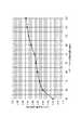
トナーボトルTから現像器100に補給されるトナーの量(補給量)は、トナーボトルTの内圧が変化する速度に応じた値となることが実験によって分かった。つまり、トナーボトルTの重量が減少することによってトナーボトルTの回転速度が目標速度よりも速くなった場合、トナーボトルTの補給量が目標とする補給量よりも増加してしまう。図9は、トナーボトルTの回転速度とトナーボトルTから1回に排出されるトナーの量(トナー排出量)との関係を実験によって測定した結果である。図9に示すように、トナーボトルTの回転速度が増加すれば、トナーボトルTから1回に排出されるトナーの量が増加していることが分かる。具体的には、トナーボトルTの回転速度が120rpmにおけるトナー排出量は、トナーボトルTの回転速度が30rpmにおけるトナー排出量に対して40[%]増加する。トナーボトルTから直接現像器100にトナーを補給する構成において、トナー排出量が40[%]も変化した場合、印刷物の濃度が変化してしまう可能性がある。 It has been experimentally found that the amount of toner replenished from the toner bottle T to the developing device 100 (replenishment amount) is a value corresponding to the speed at which the internal pressure of the toner bottle T changes. That is, when the rotation speed of the toner bottle T becomes faster than the target speed due to the decrease in the weight of the toner bottle T, the replenishment amount of the toner bottle T increases from the target replenishment amount. FIG. 9 shows the result of an experiment measuring the relationship between the rotation speed of the toner bottle T and the amount of toner discharged from the toner bottle T at one time (toner discharge amount). As shown in FIG. 9, it can be seen that if the rotation speed of the toner bottle T increases, the amount of toner discharged from the toner bottle T at one time increases. Specifically, the toner discharge amount when the rotation speed of the toner bottle T is 120 rpm is increased by 40 [%] with respect to the toner discharge amount when the rotation speed of the toner bottle T is 30 rpm. In the configuration in which the toner is directly supplied from the toner bottle T to the developing
本実施形態では、1回のトナー補給動作は、ポンプ部210が最大圧縮している状態から開始し、ポンプ部210を伸長させ、その後に圧縮させ、ポンプ部210が最大圧縮した状態で終了する。図9に示すようにトナーの補給量は、ポンプ部210を圧縮する際の回転速度の影響をうける。そこで、本実施形態では、ポンプ部210が圧縮を開始するまでにDCモータ(DCブラシモータ)が目標回転速度で安定するように、開始状態(すなわち、前回のトナー補給の終了状態)の位置が設計されている。
さらに、本実施形態では、トナーボトルTの回転速度をフィードバック制御することにより、トナーボトルTの重量の変化に応じたトナーボトルTの回転速度の変化を低減させる。In the present embodiment, one toner replenishment operation starts from a state where the
Furthermore, in the present embodiment, the change in the rotation speed of the toner bottle T according to the change in the weight of the toner bottle T is reduced by feedback control of the rotation speed of the toner bottle T.
フィードバック制御を高精度に行うためには、トナーボトルTの回転速度を高精度に測定することが重要である。DCモータ(DCブラシモータ)は、目標回転速度までの立ち上がりおよび停止において時間がかかるという特性を有する。したがって、DCモータ(DCブラシモータ)が目標回転速度で安定しているタイミングを検出し、回転速度を測定する必要がある。 In order to perform feedback control with high accuracy, it is important to measure the rotation speed of the toner bottle T with high accuracy. A DC motor (DC brush motor) has a characteristic that it takes time to start up and stop up to a target rotational speed. Therefore, it is necessary to detect the timing at which the DC motor (DC brush motor) is stable at the target rotational speed and measure the rotational speed.
上述したように本実施形態では、ポンプ部210が圧縮を開始するまでにDCモータ(DCブラシモータ)が目標回転速度で安定するように設計されている。よって、ポンプ部210が圧縮処理しているタイミングで回転速度を測定する。 As described above, in this embodiment, the DC motor (DC brush motor) is designed to be stabilized at the target rotational speed until the
さらに、回転位置がポンプ部210が最大限圧縮された状態で、補給動作後にトナーボトルTが停止するように、カム溝214の谷領域の幅がカム溝のピーク領域の幅に比べて広くなっている。これにより、ポンプ部210が最大限圧縮されていない状態で停止される可能性を低減させている。 Further, the width of the valley region of the
以下、駆動モータ604の回転速度が目標速度となるように、CPU601が駆動モータ604の回転駆動を制御する回転速度制御処理を、図2の制御ブロック図と図7のフローチャートに基づいて説明する。なお、図7に示す回転速度制御処理は、図2に示すCPU601がROM608に格納されたプログラムを読み出すことにより実行される。本実施形態においては、トナーボトルTから現像器100にトナーを補給する場合に、CPU601が図7に示す回転速度制御処理を実行する。つまり、CPU100は、トナー補給指示に基づき、図7に示す回転速度制御処理を実行する。なお、CPU601は、現像器100内のトナーの量が所定量よりも低下した場合にトナーボトルTから現像器100にトナーを補給する補給動作を実施すればよい。 Hereinafter, the rotational speed control process in which the
CPU601は、まず、ステップ100において、センサ出力検知回路607から出力される信号がハイレベル(論理‘H’)であるか否かを判定する。CPU601は、ポンプ部210が圧縮した状態でトナーボトルTが停止されているか否かを、センサ出力検知回路607の出力信号に基づいて判定する。つまり、今回の補給動作を適切な回転位置から開始することができるか否かを判定する。 First, in
ステップS100において、センサ出力回路607の出力信号がハイレベルであれば、CPU601はポンプ部210が最大限圧縮した後にトナーボトルTの回転駆動が停止されたと判定する。そして、CPU601はステップS101aに進み、エラーフラグISの値を0に設定する。 In step S100, if the output signal of the
一方、ステップS100において、センサ出力回路607の出力信号がローレベルであれば、CPU601はポンプ部210が圧縮している途中においてトナーボトルTの回転駆動が停止されたと判定する。ステップS100において、センサ出力回路607の出力信号がローレベルであれば、CPU601はステップS101bに進み、エラーフラグISの値を1に設定する。 On the other hand, if the output signal of the
ステップS102において、CPU601は、RAM609に記憶されたPWM値をモータ駆動回路603に設定するとともに、ENB信号をモータ駆動回路603に出力する。お、RAM609にPWM値が記憶されていなければ、CPU601は、例えば、PWM値として所定値を設定する。 In step S <b> 102, the
駆動モータ604の回転駆動が開始された後、CPU601はステップS103に進み、センサ出力検知回路203からローレベルの信号(論理‘L’)が出力されるまで待機する。 After the rotation drive of the
ステップS103において、センサ出力検知回路203からローレベルの信号が出力されることに応じて、CPU601はステップS104へ進む。 In step S103, in response to the output of the low level signal from the sensor
センサ出力検知回路203からローレベルの信号が出力されたことに応じて、CPU601は、所定クロック信号に応じたカウントを開始する。次いで、CPU601はステップS105へ進み、センサ出力検知回路203からハイレベルの信号(論理‘H’)が出力されるまで待機する。ステップS105において、センサ出力検知回路203から出力される信号がローレベルからハイレベルに変化したことに応じて、CPU601はステップS106へ進む。そして、CPU601は、ステップS106において現在のカウント値Tnを取得し、ステップS107において、駆動モータ604の回転駆動を停止する。 In response to the output of the low level signal from the sensor
カウント値Tnは、トナーボトルTが回転する回転方向において凸部220の前端がセンサフラグ204を押し上げてから、回転方向において凸部220の後端がセンサフラグ204の押し上げを解除するまでの時間を計測した値である。即ち、カウント値Tnは、凸部220によってセンサフラグ204が押し上げられている時間を計測した値である。本実施形態では、ポンプ部210の圧縮処理が終了するとセンサ出力検知回路203から出力される信号がローレベルからハイレベルに変化する。よって、CPU601はトナーボトルTから現像器100にトナーを補給する補給動作が1回(1ブロック)実施されたと判定し、CPU601がモータ駆動回路603に入力していたENB信号を停止する。これにより、駆動モータ604は停止する。 The count value Tn is the time from when the front end of the
CPU601は、ステップS103からステップS106までの処理において、センサ出力検知回路203からローレベルの信号が出力されていた時間を計測する。ここで、センサ出力検知回路203から出力された信号がローレベルとなっている期間は、トナーボトルTの回転に伴ってフラグ204が凸部220に当接していた期間に相当する。 The
CPU601は駆動モータ604の回転駆動を停止させた後、ステップS108に進む。ステップS108において、CPU601はエラーフラグISの値が0であるか否かを判定する。 The
エラーフラグISの値が0である場合は、今回の補給動作は適切な回転位置から開始されている。すなわち、今回の補給動作によって計測されたカウント値Tnが信頼できることを意味する。よって、S109において、CPU601は、カウント値Tnに基づき、RAMに記憶されているPWM設定値を補正し、回転速度制御処理を終了する。 When the value of the error flag IS is 0, the current replenishment operation is started from an appropriate rotational position. That is, it means that the count value Tn measured by the current replenishment operation is reliable. Therefore, in S109, the
CPU601は以下のようにPWM設定値を補正する。まず、カウント値Tnから今回の補給動作の回転速度V(n)を求める。カウント値Tnはフラグ204が凸部220に当接していた時間を示す。凸部220の周長は既知であるので、カウント値Tnに基づき、今回の補給動作の回転速度V(n)を求めることができる。 The
次に、以下の式に基づきPWM設定値の補正値D(n+1)を算出する。 Next, a PWM setting value correction value D (n + 1) is calculated based on the following equation.
D(n+1)=D(n)+Ki*(Vtgt−V(n))
ここで、D(n)は現在のPWM設定値(すなわち、ステップS102において設定されたPWM設定値である)、Kiは所定の比例定数、Vtgtは目標回転速度である。D (n + 1) = D (n) + Ki * (Vtgt−V (n))
Here, D (n) is the current PWM setting value (that is, the PWM setting value set in step S102), Ki is a predetermined proportional constant, and Vtgt is the target rotation speed.
PWM設定値の補正値D(n+1)は、次回の補給動作の際に使用される。 The PWM setting value correction value D (n + 1) is used in the next replenishment operation.
一方、ステップS108において、エラーフラグISの値が1である場合は、今回の補給動作は適切な回転位置から開始されていない。つまり、フラグ204が凸部220に当接している際に、DCモータ(DCブラシモータ)が目標回転速度までの立ち上がり処理の最中である可能性がある。つまり、今回の補給動作によって計測されたカウント値Tnが信頼できないことを意味する。よって、PWM設定値を補正せずに回転速度制御処理を終了させる。 On the other hand, if the value of the error flag IS is 1 in step S108, the current replenishment operation has not started from an appropriate rotational position. That is, when the
このように、本実施形態では、センサ出力検知回路203から出力される信号がローレベルからハイレベルに変化したことに応じて、カウンタ値の取得および駆動モータの停止を実行する。本実施形態において、トナーボトルTが回転する回転方向における凸部220の後端部はポンプ部210の圧縮の終了タイミングに対応するように設計されている。凸部220の後端部の検知結果を回転速度の計測時間の終了と補給動作の終了の両方を示す指標として使用している。このようにすることにより、伝達部206に設けられている凸部220の構成を簡単にすることができるとともに、CPU601の制御も簡単にすることができる。 Thus, in this embodiment, the counter value is acquired and the drive motor is stopped in response to the signal output from the sensor
本実施形態によれば、回転検知センサ203によりトナーボトルTの凸部220が検知される時間に基づいて駆動モータ604の回転速度を制御するPWM設定値を補正することによって、トナーボトルTの回転速度を目標とする回転速度に制御することができる。つまり、ポンプ部210が圧縮し始めてからポンプ部210が最大限圧縮するまでの供給動作を行った時間を計測し、計測結果に基づいて次にトナーボトルTを回転駆動させるときの回転速度を制御している。これにより、トナーボトルTの回転速度を目標とする回転速度に制御することができるので、トナーボトルTのトナー排出量を安定させることができる。 According to the present embodiment, the rotation of the toner bottle T is corrected by correcting the PWM setting value for controlling the rotation speed of the
(駆動モータの回転速度の推移)
図8は、PWM設定値、センサ出力検知回路607の出力信号、駆動モータ604の回転速度、カウント値Tn、供給動作を開始させるスタート信号、カウント開始を示すカウント開始信号、供給動作を終了させるストップ信号を示したタイミングチャート図である。(Changes in the rotational speed of the drive motor)
FIG. 8 shows the PWM set value, the output signal of the sensor
CPU601は、時刻t0においてトナーボトルTから現像器100にトナーを補給する場合、時刻t0においてスタート信号を出力する。このスタート信号が出力されたことに応じて、モータ駆動回路603が駆動モータ604に電流を供給する時間をPWM設定値(図8においてはD(n)[%])に基づいて制御し始める。さらに、CPU601は、時刻t0においてスタート信号を出力することに応じて、カウント値として0を設定する。 When the toner is replenished from the toner bottle T to the developing
モータ駆動回路603により駆動モータ604の回転駆動が開始された後、駆動モータ604の回転速度が増加し始める。このとき、センサ出力検知回路607はハイレベルの信号を出力している。つまり、トナーボトルTのポンプ部210は圧縮していない。 After the drive drive of the
次いで、時刻t1において、センサ出力検知回路607の出力信号がハイレベルの信号からローレベルの信号に変化する。CPU601はセンサ出力検知回路607の出力信号がハイレベルの信号からローレベルの信号に変化することに応じてカウント開始信号を出力する。これにより、カウント値Tnが増加し始める。このとき、センサ出力検知回路607がローレベルの信号を出力しているので、ポンプ部210が圧縮し始めている。 Next, at time t1, the output signal of the sensor
次いで、時刻t2において、センサ出力検知回路607の出力信号がローレベルの信号からハイレベルの信号に変化する。CPU601はセンサ出力検知回路607の出力信号がローレベルの信号からハイレベルの信号に変化することに応じてストップ信号を出力する。これにより、カウント値Tnの増加が停止すると共に、モータ駆動回路603により駆動モータ604の回転駆動が停止される。このとき、トナーボトルTのポンプ部210は最大限圧縮したことを示している。CPU601がモータ駆動回路603により駆動モータ604の回転駆動を停止することによって、ポンプ部210が伸長してしまう前に、トナーボトルTの回転駆動を停止させている。 Next, at time t2, the output signal of the sensor
以上の説明においては、センサ出力検知回路607の出力信号がローレベルからハイレベルに切り替わるタイミングにおいて、ポンプ部210が最大限圧縮する構成とした。ローレベルからハイレベルに切り替わるタイミングにおいてトナーボトルTの回転駆動を停止させることによって、次にトナーボトルTの回転駆動を開始した場合にトナーボトルTが吸気動作を行うことができる。これによって、トナーボトルTの排出口211に堆積したトナーを解すと共に、トナーボトルTの排出口211からトナーを排出できる。 In the above description, the
また、本実施形態によれば、トナーボトルTは駆動伝達部206の1周に亘って凸部220を2箇所設け、トナーボトルTが1回転する間に、供給動作を2回行う構成とした。しかしながら、トナーボトルTが1回転する間に1回だけ供給動作を行う構成としてもよい。この構成とする場合、トナーボトルTは駆動伝達部206に凸部220を1箇所だけ設ける構成とすればよい。なお、回転検知センサ203により凸部220が検知されることに応じてセンサ出力検知回路607からローレベルの信号が出力される間、トナーボトルTが現像器100にトナーを供給する供給動作が行われる。 Further, according to the present embodiment, the toner bottle T is provided with two
また、トナーボトルTが1回転する間に3回以上供給動作を行う構成としてもよい。この構成とする場合、トナーボトルTは駆動伝達部206に凸部220を3箇所以上設ける。なお、回転検知センサ203により凸部220が検知されることに応じてセンサ出力検知回路607からローレベルの信号が出力される間、トナーボトルTが現像器100にトナーを供給する供給動作が行われる。 Further, the supply operation may be performed three times or more while the toner bottle T rotates once. In the case of this configuration, the toner bottle T is provided with three or more
また、本実施形態においては、トナーボトルTが圧縮し始めるタイミングにおいて、センサ出力検知回路607の出力信号がハイレベルからローレベルに切り替わる構成に限定されない。つまり、トナーボトルTが圧縮し始めてから所定時間後にセンサ出力検知回路607の出力信号がハイレベルからローレベルに切り替わる構成としてもよい。同様に、本実施形態においては、トナーボトルTが最大限圧縮した後にセンサ出力検知回路607の出力信号がローレベルからハイレベルに切り替わる構成に限定されない。つまり、トナーボトルTが最大限圧縮する前にセンサ出力検知回路607の出力信号がローレベルからハイレベルに切り替わる構成としてもよい。 Further, the present embodiment is not limited to the configuration in which the output signal of the sensor
また、本実施形態においては、トナーボトルTが供給動作を行っている間に、センサ出力検知回路607がローレベルの信号を出力し、トナーボトルTが供給動作を行っていない間に、センサ出力検知回路607がハイレベルの信号を出力する構成とした。しかしながら、センサ出力検知回路607の出力信号は逆の関係であってもよい。即ち、トナーボトルTが供給動作を行っている間に、センサ出力検知回路607がハイレベルの信号を出力し、トナーボトルTが供給動作を行っていない間に、センサ出力検知回路607がローレベルの信号を出力する構成としてもよい。 In this embodiment, the sensor
また、本実施形態においては、トナーボトルTが供給動作を行っている間、ローレベルの信号が出力され続ける構成としたが、ポンプ部210が圧縮し始めたことを識別できる信号(第1の信号)と、ポンプ部210が最大限圧縮し終えたことを識別できる信号(第2の信号)が出力される構成であってもよい。センサ出力検知回路607が第1の信号を出力してから第2の信号が出力されるまでの時間に基づいて、CPU601がトナーボトルTを回転駆動させる際のPWM設定値を補正する構成とすればよい。 In the present embodiment, the low-level signal is continuously output while the toner bottle T is performing the supply operation. However, a signal (first signal) that can be used to identify that the
また、本実施形態においては、現像器100内のトナーの量が所定量よりも低下した場合に補給動作が実行される構成としたが、現像器100内のトナーの割合が所定の割合よりも低下した場合に補給動作が実施される構成としてもよい。例えば、現像器100は、トナーとキャリアとを有する2成分現像剤を用いて静電潜像を現像する構成とした場合、CPU601が現像剤の量に対するトナーの量の割合と所定の割合を比較すればよい。 In this embodiment, the replenishment operation is performed when the amount of toner in the developing
T 収容容器
100 現像器
203 回転検知センサ
207 収容部
210 ポンプ部
220 凸部
310 装着部
601 CPU
603 モータ駆動回路
604 駆動モータ
607 センサ出力検知回路
603
Claims (12)
Translated fromJapanese静電潜像を形成するために前記感光体を露光する露光手段と、
前記感光体上の前記静電潜像を現像剤を用いて現像する現像手段と、
現像剤を収容する収容部と前記収容部の内圧を変化させて前記収容部から前記現像手段へ現像剤を供給するために伸縮するポンプ部とを有する収容容器が装着される装着部と、
前記装着部に装着された収容容器を回転させ、前記装着された収容容器の回転駆動に伴い前記ポンプ部を伸縮させる駆動手段と、
前記回転している収容容器の回転速度に関する情報を取得するために、前記収容容器の所定部分を検出する検出手段と、
前記検出手段により取得された前記情報に基づいてフィードバック制御を実行し、前記収容容器の回転速度が所定速度になるように、前記駆動手段を制御する制御手段と、を有し、
前記制御手段は更に、前記ポンプ部が圧縮した状態で前記駆動手段を停止させることを特徴とする画像形成装置。A photoreceptor,
Exposure means for exposing the photoreceptor to form an electrostatic latent image;
Developing means for developing the electrostatic latent image on the photoreceptor using a developer;
A mounting portion on which a storage container having a storage portion that stores a developer and a pump portion that expands and contracts to supply developer from the storage portion to the developing unit by changing an internal pressure of the storage portion;
A driving means for rotating the storage container mounted on the mounting section and extending and contracting the pump section in accordance with the rotational drive of the mounted storage container;
Detecting means for detecting a predetermined portion of the container, in order to obtain information on the rotation speed of the container
Control means for performing feedback control based on the information acquired by the detection means, and controlling the driving means so that the rotational speed of the storage container becomes a predetermined speed,
The image forming apparatus according to claim 1, wherein the control unit further stops the driving unit in a state where the pump unit is compressed .
前記制御手段は、前記検出手段が前記所定部分の後端を検出したことに応じて前記駆動手段を停止させることを特徴とする請求項1に記載の画像形成装置。The operation of supplying the developer from the container starts from a state in which the pump unit is compressed, extends the pump unit, compresses the pump, and ends in the compressed state.
The image forming apparatus according to claim 1, wherein the control unit stops the driving unit in response to the detection unit detecting a rear end of the predetermined portion.
前記制御手段は、前記ポンプ部が圧縮し終える度に、前記検出手段により取得された前記情報に基づいて前記制御値を更新することを特徴とする請求項1又は2に記載の画像形成装置。The control means controls the rotation speed of the container based on a control value;
Wherein, every time the pump unit has finished compressed image forming apparatus according to claim 1or 2, characterized in that updating the control value based on the information acquired by the detection means.
前記制御値は前記駆動手段に供給すべき電流を制御するための値であることを特徴とする請求項4または5に記載の画像形成装置。The driving means is a DC motor;
The image forming apparatus according to claim4 or5, characterized in that a value for controlling the current to be supplied to said drive means the control value.
前記ポンプ部は前記カム溝に応じて伸縮することを特徴とする請求項8に記載の画像形成装置。The conversion unit includes a cam groove that rotates with the rotation of the container, and a member that engages with the cam groove and is connected to the pump unit.
The image forming apparatus according to claim8 , wherein the pump unit expands and contracts according to the cam groove.
前記検出手段が前記回転している収容容器の前記所定部分を検出する期間は、前記ポンプ部が前記現像剤を前記収容容器から前記現像手段へ供給する期間に対応することを特徴とする請求項1乃至9のいずれか一項に記載の画像形成装置。The period during which the detection unit detects the predetermined portion of the rotating storage container corresponds to a period during which the pump unit supplies the developer from the storage container to the development unit. The image forming apparatus according to any one of 1 to 9.
Priority Applications (5)
| Application Number | Priority Date | Filing Date | Title |
|---|---|---|---|
| JP2013159297AJP6238624B2 (en) | 2013-07-31 | 2013-07-31 | Image forming apparatus |
| EP14178772.1AEP2833217B1 (en) | 2013-07-31 | 2014-07-28 | Image forming apparatus |
| US14/444,820US9417559B2 (en) | 2013-07-31 | 2014-07-28 | Image forming apparatus |
| CN201410362646.4ACN104345606B (en) | 2013-07-31 | 2014-07-28 | Image forming apparatus with a toner supply device |
| US15/189,848US9746824B2 (en) | 2013-07-31 | 2016-06-22 | Image forming apparatus |
Applications Claiming Priority (1)
| Application Number | Priority Date | Filing Date | Title |
|---|---|---|---|
| JP2013159297AJP6238624B2 (en) | 2013-07-31 | 2013-07-31 | Image forming apparatus |
Publications (3)
| Publication Number | Publication Date |
|---|---|
| JP2015031736A JP2015031736A (en) | 2015-02-16 |
| JP2015031736A5 JP2015031736A5 (en) | 2016-09-08 |
| JP6238624B2true JP6238624B2 (en) | 2017-11-29 |
Family
ID=51224863
Family Applications (1)
| Application Number | Title | Priority Date | Filing Date |
|---|---|---|---|
| JP2013159297AActiveJP6238624B2 (en) | 2013-07-31 | 2013-07-31 | Image forming apparatus |
Country Status (4)
| Country | Link |
|---|---|
| US (2) | US9417559B2 (en) |
| EP (1) | EP2833217B1 (en) |
| JP (1) | JP6238624B2 (en) |
| CN (1) | CN104345606B (en) |
Cited By (1)
| Publication number | Priority date | Publication date | Assignee | Title |
|---|---|---|---|---|
| US11307710B2 (en) | 2019-06-13 | 2022-04-19 | Sharp Kabushiki Kaisha | Position detecting device including antenna function and display device |
Families Citing this family (4)
| Publication number | Priority date | Publication date | Assignee | Title |
|---|---|---|---|---|
| JP6173102B2 (en)* | 2013-07-31 | 2017-08-02 | キヤノン株式会社 | Image forming apparatus |
| JP6202952B2 (en)* | 2013-09-06 | 2017-09-27 | キヤノン株式会社 | Image forming apparatus |
| JP6576208B2 (en)* | 2015-10-26 | 2019-09-18 | キヤノン株式会社 | Image forming apparatus |
| CN205247066U (en)* | 2015-12-09 | 2016-05-18 | 上福全球科技股份有限公司 | Powdered carbon box |
Family Cites Families (19)
| Publication number | Priority date | Publication date | Assignee | Title |
|---|---|---|---|---|
| US5903806A (en)* | 1996-08-07 | 1999-05-11 | Konica Corporation | Developing agent replenishing apparatus and cartridge |
| US5794107A (en)* | 1996-09-09 | 1998-08-11 | Xerox Corporation | Toner container with molded spring |
| US6289182B1 (en)* | 2000-02-18 | 2001-09-11 | Toshiba Tec Kabushiki Kaisha | Method and apparatus for discriminating toner bottle types, stirring toner, and detecting the amount of remaining toner |
| US6731897B2 (en)* | 2002-02-21 | 2004-05-04 | Konica Corporation | Powder or toner accommodating container |
| JP2004196322A (en)* | 2002-12-17 | 2004-07-15 | Konica Minolta Holdings Inc | Powder holding container and powder holding product, toner holding container and toner holding product, and toner supply apparatus |
| JP2005257792A (en)* | 2004-03-09 | 2005-09-22 | Murata Mach Ltd | Toner supply device |
| JP2007093931A (en)* | 2005-09-28 | 2007-04-12 | Brother Ind Ltd | Developing cartridge and image forming apparatus |
| US7447449B2 (en)* | 2006-06-20 | 2008-11-04 | Xerox Corporation | Cleaner subsystem fault detection |
| JP2009265369A (en)* | 2008-04-25 | 2009-11-12 | Toshiba Corp | Image forming apparatus, process cartridge, remaining toner quantity detector, and remaining toner quantity detection means |
| CN103869666B (en)* | 2009-03-30 | 2017-10-03 | 佳能株式会社 | Developer replenishing container and developer supplying system |
| CN104238314B (en)* | 2009-03-30 | 2019-01-15 | 佳能株式会社 | Developer supply case and developer supply system |
| JP5777469B2 (en) | 2010-09-29 | 2015-09-09 | キヤノン株式会社 | Developer supply container and developer supply system |
| JP5836736B2 (en)* | 2010-09-29 | 2015-12-24 | キヤノン株式会社 | Developer supply container, developer supply system, and image forming apparatus |
| JP2012093543A (en)* | 2010-10-27 | 2012-05-17 | Canon Finetech Inc | Image forming device |
| JP5836704B2 (en)* | 2011-08-29 | 2015-12-24 | キヤノン株式会社 | Developer supply container and developer supply system |
| US8653773B2 (en)* | 2012-02-02 | 2014-02-18 | Lexmark Internatonal, Inc. | Method for calibrating a drive motor for a toner metering device in an imaging apparatus |
| JP6192389B2 (en)* | 2013-07-04 | 2017-09-06 | キヤノン株式会社 | Image forming apparatus |
| JP2015014663A (en)* | 2013-07-04 | 2015-01-22 | キヤノン株式会社 | Image forming apparatus and toner storage container |
| JP6173102B2 (en)* | 2013-07-31 | 2017-08-02 | キヤノン株式会社 | Image forming apparatus |
- 2013
- 2013-07-31JPJP2013159297Apatent/JP6238624B2/enactiveActive
- 2014
- 2014-07-28CNCN201410362646.4Apatent/CN104345606B/enactiveActive
- 2014-07-28USUS14/444,820patent/US9417559B2/enactiveActive
- 2014-07-28EPEP14178772.1Apatent/EP2833217B1/enactiveActive
- 2016
- 2016-06-22USUS15/189,848patent/US9746824B2/enactiveActive
Cited By (1)
| Publication number | Priority date | Publication date | Assignee | Title |
|---|---|---|---|---|
| US11307710B2 (en) | 2019-06-13 | 2022-04-19 | Sharp Kabushiki Kaisha | Position detecting device including antenna function and display device |
Also Published As
| Publication number | Publication date |
|---|---|
| US20160299467A1 (en) | 2016-10-13 |
| JP2015031736A (en) | 2015-02-16 |
| US9746824B2 (en) | 2017-08-29 |
| US20150037072A1 (en) | 2015-02-05 |
| EP2833217A1 (en) | 2015-02-04 |
| CN104345606B (en) | 2019-04-26 |
| CN104345606A (en) | 2015-02-11 |
| US9417559B2 (en) | 2016-08-16 |
| EP2833217B1 (en) | 2017-09-06 |
Similar Documents
| Publication | Publication Date | Title |
|---|---|---|
| JP6173102B2 (en) | Image forming apparatus | |
| US9098018B2 (en) | Developing device and image forming apparatus provided therewith | |
| JP6238624B2 (en) | Image forming apparatus | |
| JP6202952B2 (en) | Image forming apparatus | |
| JP2018004792A (en) | Developing device, developer replenishment system including the same, and image forming apparatus | |
| US20140193166A1 (en) | Image forming apparatus | |
| US8406643B2 (en) | Image forming apparatus, method, and program storage medium | |
| JP5623267B2 (en) | Image forming apparatus | |
| JP2019003132A (en) | Image formation apparatus | |
| JP6779750B2 (en) | Image forming device | |
| JP2021179557A (en) | Image forming apparatus, control method of image forming apparatus, and program | |
| JP7302632B2 (en) | Waste toner container and image forming apparatus | |
| JP7338288B2 (en) | image forming device | |
| JP2018025594A (en) | Image forming apparatus | |
| JP2019040093A (en) | Image forming apparatus | |
| JP2018025616A (en) | Image forming apparatus | |
| JP2020091451A (en) | Image forming apparatus | |
| JP2023060921A (en) | Image forming apparatus | |
| JPH10260579A (en) | Image forming device | |
| JP2018049229A (en) | Image forming apparatus and developer supply method | |
| JP2020086165A (en) | Image formation device | |
| JP2015052668A (en) | Image formation device | |
| JP2020091450A (en) | Image forming apparatus | |
| JP2019139048A (en) | Image formation device | |
| JP2019003089A (en) | Developer supply apparatus and image formation apparatus |
Legal Events
| Date | Code | Title | Description |
|---|---|---|---|
| A521 | Request for written amendment filed | Free format text:JAPANESE INTERMEDIATE CODE: A523 Effective date:20160722 | |
| A621 | Written request for application examination | Free format text:JAPANESE INTERMEDIATE CODE: A621 Effective date:20160722 | |
| A977 | Report on retrieval | Free format text:JAPANESE INTERMEDIATE CODE: A971007 Effective date:20170410 | |
| A131 | Notification of reasons for refusal | Free format text:JAPANESE INTERMEDIATE CODE: A131 Effective date:20170425 | |
| A521 | Request for written amendment filed | Free format text:JAPANESE INTERMEDIATE CODE: A523 Effective date:20170623 | |
| TRDD | Decision of grant or rejection written | ||
| A01 | Written decision to grant a patent or to grant a registration (utility model) | Free format text:JAPANESE INTERMEDIATE CODE: A01 Effective date:20171003 | |
| A61 | First payment of annual fees (during grant procedure) | Free format text:JAPANESE INTERMEDIATE CODE: A61 Effective date:20171031 | |
| R151 | Written notification of patent or utility model registration | Ref document number:6238624 Country of ref document:JP Free format text:JAPANESE INTERMEDIATE CODE: R151 |