JP6235591B2 - Sidestream breathing gas sampling system with flexible accessories and removable water trap - Google Patents
Sidestream breathing gas sampling system with flexible accessories and removable water trapDownload PDFInfo
- Publication number
- JP6235591B2 JP6235591B2JP2015527047AJP2015527047AJP6235591B2JP 6235591 B2JP6235591 B2JP 6235591B2JP 2015527047 AJP2015527047 AJP 2015527047AJP 2015527047 AJP2015527047 AJP 2015527047AJP 6235591 B2JP6235591 B2JP 6235591B2
- Authority
- JP
- Japan
- Prior art keywords
- housing
- connector
- patient interface
- assembly
- water trap
- Prior art date
- Legal status (The legal status is an assumption and is not a legal conclusion. Google has not performed a legal analysis and makes no representation as to the accuracy of the status listed.)
- Expired - Fee Related
Links
Images


Classifications
- A—HUMAN NECESSITIES
- A61—MEDICAL OR VETERINARY SCIENCE; HYGIENE
- A61M—DEVICES FOR INTRODUCING MEDIA INTO, OR ONTO, THE BODY; DEVICES FOR TRANSDUCING BODY MEDIA OR FOR TAKING MEDIA FROM THE BODY; DEVICES FOR PRODUCING OR ENDING SLEEP OR STUPOR
- A61M16/00—Devices for influencing the respiratory system of patients by gas treatment, e.g. ventilators; Tracheal tubes
- A61M16/08—Bellows; Connecting tubes ; Water traps; Patient circuits
- A61M16/0808—Condensation traps
- A—HUMAN NECESSITIES
- A61—MEDICAL OR VETERINARY SCIENCE; HYGIENE
- A61B—DIAGNOSIS; SURGERY; IDENTIFICATION
- A61B5/00—Measuring for diagnostic purposes; Identification of persons
- A61B5/08—Measuring devices for evaluating the respiratory organs
- A61B5/082—Evaluation by breath analysis, e.g. determination of the chemical composition of exhaled breath
- A—HUMAN NECESSITIES
- A61—MEDICAL OR VETERINARY SCIENCE; HYGIENE
- A61B—DIAGNOSIS; SURGERY; IDENTIFICATION
- A61B5/00—Measuring for diagnostic purposes; Identification of persons
- A61B5/08—Measuring devices for evaluating the respiratory organs
- A61B5/097—Devices for facilitating collection of breath or for directing breath into or through measuring devices
- A—HUMAN NECESSITIES
- A61—MEDICAL OR VETERINARY SCIENCE; HYGIENE
- A61M—DEVICES FOR INTRODUCING MEDIA INTO, OR ONTO, THE BODY; DEVICES FOR TRANSDUCING BODY MEDIA OR FOR TAKING MEDIA FROM THE BODY; DEVICES FOR PRODUCING OR ENDING SLEEP OR STUPOR
- A61M16/00—Devices for influencing the respiratory system of patients by gas treatment, e.g. ventilators; Tracheal tubes
- A61M16/0057—Pumps therefor
- A—HUMAN NECESSITIES
- A61—MEDICAL OR VETERINARY SCIENCE; HYGIENE
- A61M—DEVICES FOR INTRODUCING MEDIA INTO, OR ONTO, THE BODY; DEVICES FOR TRANSDUCING BODY MEDIA OR FOR TAKING MEDIA FROM THE BODY; DEVICES FOR PRODUCING OR ENDING SLEEP OR STUPOR
- A61M16/00—Devices for influencing the respiratory system of patients by gas treatment, e.g. ventilators; Tracheal tubes
- A61M16/06—Respiratory or anaesthetic masks
- A61M16/0666—Nasal cannulas or tubing
- A—HUMAN NECESSITIES
- A61—MEDICAL OR VETERINARY SCIENCE; HYGIENE
- A61M—DEVICES FOR INTRODUCING MEDIA INTO, OR ONTO, THE BODY; DEVICES FOR TRANSDUCING BODY MEDIA OR FOR TAKING MEDIA FROM THE BODY; DEVICES FOR PRODUCING OR ENDING SLEEP OR STUPOR
- A61M16/00—Devices for influencing the respiratory system of patients by gas treatment, e.g. ventilators; Tracheal tubes
- A61M16/08—Bellows; Connecting tubes ; Water traps; Patient circuits
- A61M16/0816—Joints or connectors
- A61M16/0841—Joints or connectors for sampling
- A61M16/085—Gas sampling
- G—PHYSICS
- G01—MEASURING; TESTING
- G01N—INVESTIGATING OR ANALYSING MATERIALS BY DETERMINING THEIR CHEMICAL OR PHYSICAL PROPERTIES
- G01N33/00—Investigating or analysing materials by specific methods not covered by groups G01N1/00 - G01N31/00
- G01N33/0004—Gaseous mixtures, e.g. polluted air
- G01N33/0009—General constructional details of gas analysers, e.g. portable test equipment
- G01N33/0011—Sample conditioning
- G01N33/0014—Sample conditioning by eliminating a gas
- A—HUMAN NECESSITIES
- A61—MEDICAL OR VETERINARY SCIENCE; HYGIENE
- A61M—DEVICES FOR INTRODUCING MEDIA INTO, OR ONTO, THE BODY; DEVICES FOR TRANSDUCING BODY MEDIA OR FOR TAKING MEDIA FROM THE BODY; DEVICES FOR PRODUCING OR ENDING SLEEP OR STUPOR
- A61M16/00—Devices for influencing the respiratory system of patients by gas treatment, e.g. ventilators; Tracheal tubes
- A61M16/10—Preparation of respiratory gases or vapours
- A61M16/1005—Preparation of respiratory gases or vapours with O2 features or with parameter measurement
- A61M2016/102—Measuring a parameter of the content of the delivered gas
- A61M2016/103—Measuring a parameter of the content of the delivered gas the CO2 concentration
- A—HUMAN NECESSITIES
- A61—MEDICAL OR VETERINARY SCIENCE; HYGIENE
- A61M—DEVICES FOR INTRODUCING MEDIA INTO, OR ONTO, THE BODY; DEVICES FOR TRANSDUCING BODY MEDIA OR FOR TAKING MEDIA FROM THE BODY; DEVICES FOR PRODUCING OR ENDING SLEEP OR STUPOR
- A61M2202/00—Special media to be introduced, removed or treated
- A61M2202/04—Liquids
- A—HUMAN NECESSITIES
- A61—MEDICAL OR VETERINARY SCIENCE; HYGIENE
- A61M—DEVICES FOR INTRODUCING MEDIA INTO, OR ONTO, THE BODY; DEVICES FOR TRANSDUCING BODY MEDIA OR FOR TAKING MEDIA FROM THE BODY; DEVICES FOR PRODUCING OR ENDING SLEEP OR STUPOR
- A61M2205/00—General characteristics of the apparatus
- A61M2205/75—General characteristics of the apparatus with filters
- A61M2205/7536—General characteristics of the apparatus with filters allowing gas passage, but preventing liquid passage, e.g. liquophobic, hydrophobic, water-repellent membranes
Landscapes
- Health & Medical Sciences (AREA)
- Life Sciences & Earth Sciences (AREA)
- Engineering & Computer Science (AREA)
- General Health & Medical Sciences (AREA)
- Pulmonology (AREA)
- Veterinary Medicine (AREA)
- Public Health (AREA)
- Animal Behavior & Ethology (AREA)
- Heart & Thoracic Surgery (AREA)
- Biomedical Technology (AREA)
- Emergency Medicine (AREA)
- Anesthesiology (AREA)
- Hematology (AREA)
- Chemical & Material Sciences (AREA)
- Pathology (AREA)
- Physics & Mathematics (AREA)
- Molecular Biology (AREA)
- Physiology (AREA)
- Surgery (AREA)
- Medical Informatics (AREA)
- Biophysics (AREA)
- Medicinal Chemistry (AREA)
- Combustion & Propulsion (AREA)
- Food Science & Technology (AREA)
- Analytical Chemistry (AREA)
- Immunology (AREA)
- General Physics & Mathematics (AREA)
- Biochemistry (AREA)
- Otolaryngology (AREA)
- Sampling And Sample Adjustment (AREA)
- Measurement Of The Respiration, Hearing Ability, Form, And Blood Characteristics Of Living Organisms (AREA)
Description
Translated fromJapanese換気装置は、患者の呼吸を支援又は代替するために、患者の気道へ加圧された気体の流れ、例えば空気及び/又は空気と追加の(補足の)酸素との混合物を供給する。換気装置は、(吸入に対応する)吸気相の間に気体が患者に提供され、続いて(呼気(吐き出し)に対応する)呼気相の間に患者から受容されるように、周期的に動作する。副流(sidestream)気体分析器は、機械的な換気又は通常の呼吸の間に患者(の呼吸気体流)によって吸入及び吐き出される患者の呼吸気体の一部分を、例えば患者気道インターフェイス及び延長ラインを含むサンプリング管を通して、例えば気体分析ベンチのようなセンサに向かって方向転換させる。 The ventilator provides a pressurized gas flow, such as air and / or a mixture of air and additional (supplemental) oxygen, to the patient's respiratory tract to assist or replace the patient's breathing. The ventilator operates periodically so that gas is provided to the patient during the inspiratory phase (corresponding to inhalation) and subsequently received from the patient during the expiratory phase (corresponding to exhalation (exhaling)) To do. The sidestream gas analyzer includes a portion of the patient's respiratory gas that is inhaled and exhaled by the patient during mechanical ventilation or normal breathing, such as a patient airway interface and an extension line Turn through the sampling tube towards a sensor such as a gas analysis bench.
センサは、呼吸気体流内の少なくとも一つの気体、例えば二酸化炭素(CO2)を検出及び分析するために使用されてもよい。しかしながら、水分の存在は一般的に、呼吸気体流内の様々な気体の正確な検出に影響を及ぼす。ウォーターフィルタ又はウォータートラップ(除水器)は、呼吸気体流から水分を除去又は低減するために使用される。ウォーターフィルタ又はウォータートラップは、しばしば従来型の副流式人工呼吸器気体分析システムの使い捨ての患者インターフェイス内の患者付属品(アクセサリー)の中に含まれ、従って、例えば空気通路及びカニューレのような他の患者付属品と一緒に、使用の度に廃棄される。加えて、サンプリングチャンバは、ウォータートラップフィルタから乾いた呼吸気体流を受容し、制御された体積のサンプル気体を副流気体分析ベンチに分析のために渡す。ウォータートラップと同様に、サンプリングチャンバもまた、従来型の副流式人工呼吸器気体分析システムの患者インターフェイス内に含められる可能性があり、従って使用の度に廃棄される。そのような副流式サンプリングアクセサリーは、使い捨ての患者インターフェイスにウォータートラップ及びサンプリングチャンバの費用の負担をかける。The sensor may be used to detect and analyze at least one gas in the respiratory gas stream, such as carbon dioxide (CO2 ). However, the presence of moisture generally affects the accurate detection of various gases within the respiratory gas stream. Water filters or water traps are used to remove or reduce moisture from the breathing gas stream. Water filters or water traps are often included in patient accessories (accessories) within the disposable patient interface of conventional side-flow ventilator gas analysis systems, and thus other such as air passages and cannulas, for example. Along with any patient accessories, it is discarded with each use. In addition, the sampling chamber receives a dry respiratory gas stream from the water trap filter and passes a controlled volume of sample gas to the sidestream gas analysis bench for analysis. Similar to the water trap, the sampling chamber may also be included in the patient interface of a conventional sidestream ventilator gas analysis system and is therefore discarded with each use. Such sidestream sampling accessories place a cost of water trap and sampling chamber on a disposable patient interface.
本発明の一つの態様において、取り外し可能なウォータートラップ装置は、患者インターフェイス組立品(アセンブリ)から受容された呼吸気体流から水分を取り除き、分析ベンチによる呼吸気体流内の少なくとも一つの気体の監視を可能にする。装置は、ハウジング、上流側ウォータートラップ接続器及びフィルタ組立品を有する。ハウジングは第一の部分を有し、第一の部分はテザー組立品受容器に挿入取り付け可能であり、テザーラインを経由して呼吸気流を供給するために装置の分析ベンチへの接続を可能にする。上流側ウォータートラップ接続器は、サンプル流ラインを経由して呼吸気体流を受容するために、患者インターフェイス組立品内のサンプル流ラインの下流側患者インターフェイス接続器に取り付け可能である。フィルタ組立品は、ハウジング内に挿入可能に収容され、気体流から水分を取り除くように構成される。フィルタ組立品は、テザー組立品受容器内でテザーラインに取り付け可能な下流側ウォータートラップ接続器を含む。フィルタ組立品は、患者インターフェイス組立品とは独立に交換可能である。 In one embodiment of the present invention, the removable water trap device removes moisture from the breathing gas stream received from the patient interface assembly and monitors at least one gas in the breathing gas stream by the analysis bench. to enable. The apparatus has a housing, an upstream water trap connector and a filter assembly. The housing has a first part that is insertable into the tether assembly receptacle and allows connection of the instrument to an analysis bench for supplying respiratory airflow via the tether line To do. An upstream water trap connector can be attached to the patient interface connector downstream of the sample flow line in the patient interface assembly for receiving respiratory gas flow via the sample flow line. The filter assembly is insertably received within the housing and is configured to remove moisture from the gas stream. The filter assembly includes a downstream water trap connector that can be attached to the tether line within the tether assembly receptacle. The filter assembly can be replaced independently of the patient interface assembly.
本発明の一つの他の態様において、副流式呼吸気体分析システムは、患者インターフェイス組立品から受容された呼吸気体流から水分を取り除くための、取り外し可能なウォータートラップ;呼吸気体流内の少なくとも一つの気体を検出及び分析するための、気体分析ベンチ;及び気体分析ベンチに呼吸気体流を供給するために気体分析ベンチと患者インターフェイス組立品との間に接続された、テザー組立品、を含む。テザー組立品は、ウォータートラップを挿入可能に受容するように構成されたテザー組立品受容器を有する。ウォータートラップは、テザー組立品受容器内の受容器開口部に挿入可能な第一の部分を有し、テザー組立品を経由して気体分析ベンチへの呼吸気体流の供給を可能にする、ハウジング;ハウジング内に挿入可能であり、呼吸気体流から水分を取り除くように構成されたフィルタ組立品;水分が取り除かれた状態で呼吸気体を供給するために、テザー組立品受容器を経由してウォータートラップをテザー組立品に接続するための、下流側ウォータートラップ接続器;及び呼吸気体流を受容するために、ウォータートラップを患者インターフェイス組立品に接続させるための、上流側ウォータートラップ接続器、を含む。 In one other aspect of the present invention, a side flow respiratory gas analysis system includes a removable water trap for removing moisture from a respiratory gas flow received from a patient interface assembly; at least one in the respiratory gas flow. A gas analysis bench for detecting and analyzing two gases; and a tether assembly connected between the gas analysis bench and the patient interface assembly for providing a breathing gas flow to the gas analysis bench. The tether assembly has a tether assembly receptacle configured to removably receive a water trap. The water trap has a first portion that can be inserted into a receiver opening in a tether assembly receiver and allows a supply of breathing gas flow to the gas analysis bench via the tether assembly. A filter assembly that is insertable into the housing and configured to remove moisture from the breathing gas stream; to supply breathing gas in a dehydrated state, the water is passed through a tether assembly receptacle A downstream water trap connector for connecting the trap to the tether assembly; and an upstream water trap connector for connecting the water trap to the patient interface assembly for receiving respiratory gas flow. .
本発明の一つの更に他の態様において、患者インターフェイス組立品から受容された呼吸気体流から水分を取り除き、呼吸気体流内の少なくとも一つの気体を分析ベンチによって監視することを可能にするための取り外し可能なウォータートラップ装置は、ハウジング、フィルタ組立品及び接続器を含む。ハウジングは第一の部分及び第二の部分を含み、第一の部分は、テザー組立品受容器内の開口部に挿入可能であり、テザーラインを経由して呼吸気体流を供給するためにウォータートラップ装置の分析ベンチへの接続を可能にする。ハウジングは複数の溝を画成し、複数の溝は対応する複数の案内突起とスライド可能に連絡する(slidably communicate)ように構成され、複数の案内突起はテザー組立品受容器内の開口部の内表面から突出する。複数の溝のそれぞれは曲がっており、ハウジングの第一の部分をテザー組立品受容器の中にロックするために、ハウジングの回転動作を加えることを必要とする。フィルタ組立品は、ハウジング内に挿入可能に収容され、呼吸気体流から水分を取り除くように構成される。フィルタ組立品は、テザー組立品受容器内でテザーラインに接続するように構成されたシール先端を含む。接続器はハウジングの第二の部分を含み、延長ラインを経由して呼吸気体流を受容するために、患者インターフェイス組立品の補完的な接続器に取り付け可能である。 In yet another aspect of the present invention, removal to remove moisture from the respiratory gas stream received from the patient interface assembly and to allow at least one gas in the respiratory gas stream to be monitored by the analysis bench. Possible water trap devices include a housing, a filter assembly and a connector. The housing includes a first portion and a second portion, the first portion being insertable into an opening in the tether assembly receiver and having water to supply a breathing gas flow via the tether line. Allows connection of the trap device to the analysis bench. The housing defines a plurality of grooves, wherein the plurality of grooves are configured to slidably communicate with the corresponding plurality of guide protrusions, the plurality of guide protrusions being defined in the openings in the tether assembly receptacle. Projects from the inner surface. Each of the plurality of grooves is bent and requires the housing to be rotated to lock the first portion of the housing into the tether assembly receptacle. The filter assembly is insertably received within the housing and is configured to remove moisture from the breathing gas stream. The filter assembly includes a seal tip configured to connect to a tether line within a tether assembly receptacle. The connector includes a second portion of the housing and is attachable to a complementary connector of the patient interface assembly for receiving respiratory gas flow via an extension line.
以下の詳細な説明において、説明の目的であって限定の目的でなく、具体的詳細を開示する複数の例示的な実施形態が、本教示による一つの実施形態の完全な理解を提供するために説明される。しかしながら、本明細書において開示される具体的な詳細から離れた、本教示による複数の他の実施形態が、添付の特許請求の範囲の範囲内に留まることが、本開示の利益を有する当業者にとって明らかであろう。さらに、よく知られた装置及び方法の記述は、例示的な実施形態の記述を分かりにくくしないように、省略され得る。そのような方法及び装置は、明確に本教示の範囲内に含まれる。 In the following detailed description, for purposes of explanation and not limitation, multiple exemplary embodiments disclosing specific details are provided in order to provide a thorough understanding of one embodiment in accordance with the present teachings. Explained. However, one of ordinary skill in the art having the benefit of this disclosure will appreciate that other embodiments in accordance with the present teachings, apart from the specific details disclosed herein, remain within the scope of the appended claims. It will be obvious to you. Further, descriptions of well-known devices and methods may be omitted so as not to obscure the description of the exemplary embodiments. Such methods and apparatus are clearly included within the scope of the present teachings.
図1は、一つの代表的な実施形態による取り外し可能なウォータートラップを含む、副流式呼吸気体分析システムの機能ブロック図である。 FIG. 1 is a functional block diagram of a side flow respiratory gas analysis system including a removable water trap according to one exemplary embodiment.
図1を参照すると、副流式呼吸気体分析システム100は、取り外し可能なフィルタ又はウォータートラップ110、モジュール組立品又は気体分析ベンチ(台)120、テザー(tether)組立品130及び患者インターフェイス組立品140を含む。気体分析ベンチ120及びテザー組立品130は、ホスト装置150内に含められてもよい。概して、サンプル流を指示する矢印によって示されるように、採取された呼吸気体流は、患者から患者インターフェイス組立品140を経由して受容され、ウォータートラップ110を経由して気体分析ベンチ120へ向けて通過し、検出器125において分析され、そして排気管151を通ってホスト装置150を出る。 Referring to FIG. 1, a side flow respiratory
ウォータートラップ110は、患者インターフェイス組立品140から受容された呼吸気体流から水分を取り去る。ウォータートラップ110は交換可能であってもよく、その一つの例は、フィリップス(登録商標)整理番号第2011PF02525に記述されている。この出願は参照により本明細書に取り込まれる。ウォータートラップ110はハウジング111を含み、ハウジング111の一部分は、テザー組立品130内のテザー組立品受容器132に(例えば挿入により)取り付け可能である。ウォータートラップ110は、上流側ウォータートラップ接続器115及びハウジング111の反対側の端に下流側ウォータートラップ接続器116を更に含む。上流側ウォータートラップ接続器115は、下流側患者インターフェイス接続器を介して患者インターフェイス組立品140のサンプル流に接続する。サンプル流ラインの例は、(任意的な)延長ライン148及び患者インターフェイス組立品140の空気通路を含む。上流側ウォータートラップ接続器115は、(図1に描かれるように)下流側患者インターフェイス接続器143を介して延長ライン148に接続するように、又は下流側患者インターフェイス接続器141を介して直接的に空気通路145に接続するように構成されている。下流側ウォータートラップ接続器116は、テザー組立品130内のウォータートラップ受容器132を経由してテザーライン136に接続する。ウォータートラップ110は、例えば、テザー組立品受容器132に取り付け可能で、一人以上の患者のために使用され、患者インターフェイス組立品140の複数の要素が取り換え又は交換されるかどうかに関わらず、使い捨て可能(ディスポーザブル)なフィルタカートリッジとして具体化されてもよい。ウォータートラップ110の詳細は、図2乃至9を参照して以下に記述される。 The
テザー組立品130は、気体分析ベンチ120にフィルタ処理した呼吸気体流を供給するために、ウォータートラップ110と気体分析ベンチ120との間に接続される。テザー組立品130は、テザー組立品受容器132を含む。テザー組立品受容器132は、ウォータートラップ110のハウジング111の挿入可能な部分を受容するように構成された開口部を画成してもよい。テザー組立品130は、テザーライン136を経由してテザー組立品受容器132に接続されたサンプリングチャンバ又はサンプルセル134を更に含む。サンプルセル134は、例えば、分析のために副流気体分析ベンチ120に制御された(既知の)体積のサンプル気体を渡す、光学的なサンプルセルであってもよい。図示された実施形態において、サンプルセル134は、気体分析ベンチ120に対して取り外し可能に接続されることができる。例えば、気体分析ベンチ120は、図示された実施例に示されるように、サンプルセル134を挿入可能に受容するように構成されたサンプルセル受容器123を含んでもよい。図示された実施形態において、サンプルセル134は現場交換可能な品物であり、気体分析ベンチ120の内部の物である。それは、必要に応じてのみ、交換されるように意図される。他の構成において、サンプルセル134は、交換の容易さのために外部から交換可能であってもよい。代替的に、サンプルセル134は、使い捨ての患者インターフェイス組立品140の一部として包含されてもよい。 A
図示された実施形態において、気体分析ベンチ120は、ポンプモータ122、ポンプヘッド126、サンプルセル受容器123、検出器125及びプロセッサ127を含む。それらの全て又はいくつかは、プリント基板(PCB)124に乗せられており、呼吸気体流中の、例えばCO2のような少なくとも一つの気体を検出及び分析することを可能にする。ポンプモータ122、ポンプヘッド126は、サンプルセル134を通して、サンプルセル受容器123へ呼吸気体流を送り込み(ポンプし)、排気管151へ出す。検出器125は、サンプルセル受容器123の一部であり、又は気体分析ベンチ120のPCB上に併合されてもよい。検出器125は、サンプルセル134によって渡された呼吸気体流によって信号を受容し、呼吸気体流中の、例えばCO2のような少なくとも一つの気体の量を検出する。検出器125は、例えば、測定されている気体のスペクトル範囲に対して感受性がある、光ダイオード検出器、光導電性検出器又は光起電性検出器若しくは焦電気性検出器を含み得る。例えば、セレン化鉛、ケイ化白金又はアンチモン化インジウムが検出器用であり得る。In the illustrated embodiment, the
プロセッサ127は、検出結果を分析するための、検出器125を含む、気体分析ベンチ120の様々な構成要素の動作を制御するように構成されている。当業者によって明確に理解され得るように、プロセッサ127は、少なくとも一部は、ソフトウェア制御されたマイクロプロセッサ、ハードワイヤードロジック回路又はそれらの組合せを使用して物理的に実装されてもよい。例えば、プロセッサ127は、副流式呼吸気体分析システム100の機能性を提供及び/又は制御するためのメモリ(図示なし)と併用して、気流検出及び分析プロセスを含む一つ以上のソフトウェアアルゴリズムを実行するように構成されたマイクロプロセッサとして実装されてもよい。すなわち、プロセッサ127は、それが本明細書において記述される副流式呼吸気体流分析システム100並びに呼吸気体検出及び分析プロセスの様々な機能を実行することを可能にする実行可能なソフトウェアコードを保存するための不揮発性メモリを含んでもよい。気体分析ベンチ120は、プロセッサ127の制御及びプログラミングを可能にするためのユーザーインターフェイス(図示なし)、分析結果をリアルタイム又はほとんどリアルタイムで表示するためのディスプレイ(図示なし)及び/又は分析結果を保存するためのメモリ(図示なし)を更に含んでもよい。 The
患者インターフェイス組立品140は、患者とウォータートラップ110との間に接続される。患者インターフェイス組立品140は、例えばカニューレ144及び空気通路145のような患者付属品を含む。カニューレ144は、例えば、鼻カニューレ、鼻−口サンプリングカニューレ又は鼻−口酸素供給鼻カニューレであってもよい。特に、患者付属品は、従来の使い捨ての一回使用のウォータートラップのようなウォータートラップを含まない。ウォータートラップの機能性は、記述される、取り外し可能なウォータートラップ110によって異なる方法で提供される。また、様々な実施形態において、患者付属品は、従来の使い捨ての一回使用のサンプルセルを含まなくてもよい。サンプルセルの機能性は、前述の、取り外し可能なサンプルセル134によって異なる方法で提供される。患者インターフェイス組立品140は、延長ライン148を更に有する。延長ライン148は、例えばNAFION(登録商標)で形成された乾燥器ラインを含んでもよい。延長ライン148は、下流側患者インターフェイス接続器141と接続するように構成された上流側患者インターフェイス接続器142、及びウォータートラップ110の上流側ウォータートラップ接続器115と接続するように構成された下流側患者インターフェイス接続器143を含む。下流側患者インターフェイス接続器141及び143のそれぞれ及び上流側患者インターフェイス接続器142並びにウォータートラップ110の上流側ウォータートラップ接続器115は、後述するように副流式呼吸気体分析システム100の組立て及び分解を単純化するために、クイックリリース接続器であってもよい。一つの代替的な実施形態において、患者インターフェイス組立品140は、挿管された患者への使用のための主流気体サンプリングアダプタであってもよい。また、様々な構成において、患者インターフェイス組立品140は、延長ライン148を使用しなくてもよく、その場合は、上流側ウォータートラップ接続器115は下流側患者インターフェイス接続器141に直接的に接続されてもよい。 Patient interface assembly 140 is connected between the patient and
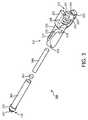
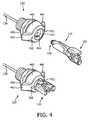
図2は、一つの代表的な実施形態による、取り外し可能なウォータートラップの上面図、側面図及び端面図を提供する。図3は、一つの代表的な実施形態による、取り外し可能なウォータートラップの分解斜視図である。図4は、一つの代表的な実施形態による、取り外し可能なウォータートラップ及びテザー組立品受容器の、接続解除状態及び接続状態における複数の透視図を提供する。図5は、一つの代表的な実施形態による、取り外し可能なウォータートラップ及び患者インターフェイス組立品接続器の、接続状態及び接続解除状態における複数の透視図を提供する。 FIG. 2 provides a top view, a side view, and an end view of a removable water trap, according to one exemplary embodiment. FIG. 3 is an exploded perspective view of a removable water trap, according to one exemplary embodiment. FIG. 4 provides multiple perspective views of the removable water trap and tether assembly receptacle in a disconnected state and a connected state, according to one exemplary embodiment. FIG. 5 provides multiple perspective views of the removable water trap and patient interface assembly connector in the connected and disconnected states, according to one exemplary embodiment.
図2乃至5を参照すると、ウォータートラップ110はハウジング111を含み、ハウジング111は、向かい合う両側に第一の部分210及び第二の部分220を提供する。前述したように、第一の部分210は、テザー組立品130のテザー組立品受容器132の中に取り外し可能に挿入されるように構成され、(フィルタ処理された)呼吸気体流の気体分析ベンチ120への供給を可能にする。図示された実施形態において、第一の部分210は、ハウジング111の外表面上に、代表的な溝215によって表示される、少なくとも一つの溝を画成する。溝215は、図4に示されるように、テザー組立品受容器132内の受容器開口部411の内径から突出する案内突起415とスライド可能に連絡するように構成されている。図2乃至4には一つの溝215が示されているが、本教示の範囲から逸脱することなく、ハウジング111の第一の部分210は、二つ以上の溝を画成してもよいことが理解される。例えは、第一の部分210は、ハウジング111の円周方向反対側に、図4に示されるように、受容器開口部411の内径から突出する案内突起416とスライド可能に連絡する、第二の溝を有してもよい。また、案内突起416は受容器開口部411の内径上で案内突起415の正反対に示されているが、本教示の範囲から逸脱することなく、案内突起415及び案内突起416(加えて対応する複数の溝)は、互いに対して様々な位置に配置されてもよく、且つ/或いは、複数の追加的な案内突起(及び対応する複数の溝)が含まれてもよいことが理解される。 Referring to FIGS. 2-5, the
図示された実施形態において、溝215は、曲線状に曲がって(curved)おり、溝215の全長が案内突起415に沿ってスライドすることを可能にするためには、ハウジング111の第一の部分210をテザー組立品受容器132の中に向けて押すと同時に、ハウジング111の回転動作を必要とする。溝215の曲線は、“J”字型であり、実質的に直線的な部分217が、案内突起415と連絡することによって、最初にハウジング111の第一の部分210を受容器開口部411の中に案内し、そして曲線状端部分218がハウジング111の回転動作を規定し、ロック機構を有効にする。溝215はまた、最初に溝215を案内突起415上に向けて案内するための拡張された開口部を提供する、入口部分219を含んでもよい。例えば、入口部分219は、案内突起415を直線的な部分217の中へ案内する、収束する両側面を含んでもよい。ウォータートラップ110上の押し込み・回転形状は、挿入位置の大きなばらつきを可能にする。ウォータートラップ110は、実質的に如何なる方向から差し込まれた場合でも、それ自身の中心を取り戻すことができ、例えば4分の1回転以内でロックすることができる。ウォータートラップ110は、斜面のアタッチメント又はハウジング440上で底に達して、過剰な締め付けを防止してもよい。 In the illustrated embodiment, the
代替的な実施形態において、本教示の範囲から逸脱することなく、溝215は、直線的(折れ曲がりを有しない)であってもよく、又は図2乃至4に図示された曲線形状とは異なる曲線形状を画成してもよい。例えば、溝215は“L” 字型であってもよく、ロック機構は、最初の直線的な部分から実質的に90度の角度を成すことを含む。様々な実施形態において、ロック機構は、ハウジング111の第一の部分210がテザー組立品受容器132と完全に係合するときに、例えばはじけるように(音を立てて)閉まる(snapping)感覚又はぴったりとはまる(seating)感覚のような、触知可能な応答をもたらしてもよい。例えば、第一の部分210は、案内突起415が曲線状端部分218の末端に配置されるときに、完全に係合される。図3を参照して以下に説明されるように、下流側ウォータートラップ接続器116は、ハウジング111の末端から延び、挿入可能なフィルタ管365に取り付けられてもよい。 In alternative embodiments, the
上流側ウォータートラップ接続器115は、ハウジング111の反対側の端に配置される。図示された実施形態において、上流側ウォータートラップ接続器115は、例えば、ハウジング111の第二の部分220、複数のタブ254,255、突出部材256及びシール部材257を有する。ハウジング111の第二の部分220は、代表的なフランジ221及び222によって表示される、ハウジング111の第一の部分210の外周を超えて延びる少なくとも一つのフランジを含む。フランジ221及び222は、例えば、前述のように溝215を案内突起415とスライド可能に連絡するために回転動作が必要とされるときに、ハウジング111の回転動作に適する(accommodate)ように、実質的に向かい合う第二の部分220の両側に配置されている。図4に示されるように、フランジ221及び222は、ハウジング111の第一の部分210がテザー組立品受容器132と完全に係合又はロックするときに、テザー組立品受容器132上の対応する視覚的整列標識421及び422と整列又は一致してもよい。 The upstream
第二の部分220はまた、少なくとも一つのフランジ221,222に隣接した切欠き部分224を規定する。図示された実施形態において、切欠き部分224は、フランジ221及びフランジ222の間の実質的に“C”形状の切欠きである。上流側ウォータートラップ接続器115の突出部材256は切欠き部分224から延び、そしてシール部材257は突出部材256の周囲を取り囲む。シール部材257は、硬質な機構として且つ突出部材256の一部として形成されてもよい。そのとき延長ライン148の下流側患者インターフェイス接続器143は、軟質な弾性材料で作られることになる。突出部材256及びシール部材257が柔軟な下流側患者インターフェイス接続器143の中にぴったりと適合させられるときに、空気シールの状態が作り出される。下流側患者インターフェイス接続器143は、空気開口部の内表面上に対応する溝(図示なし)を有してもよい。一つの他の実施形態において、シール部材257は、延長ライン148の下流側患者インターフェイス接続器143の中にぴったりと適合させられる(fit)ときに圧縮されて空気シールをもたらす、弾性材料で形成されてもよい。本実施形態において、下流側患者インターフェイス接続器143は、より硬質な材料で作られてもよい。例えば、シール部材257は、下流側患者インターフェイス接続器143内の開口部の内表面内の対応する溝(図示なし)と連絡してもよい。加えて、図示された実施形態は、代表的な接続器タブ254及び255によって表示され、切欠き部分224の内表面から突出する、複数の接続器タブを含む。接続器タブ254及び255は、下流側患者インターフェイス接続器143の対応するスロット(図示なし)の中にぴったりと適合するように構成される。接続器タブ254及び255は、上流側ウォータートラップ接続器115が下流側患者インターフェイス接続器143と完全に係合するときに、触知可能な応答をもたらしてもよい。上流側ウォータートラップ接続器115と下流側患者インターフェイス接続器143との間の接続は、以下で図5を参照して更に説明される。 The
図3を参照すると、ウォータートラップ110はフィルタ組立品360を更に含む。フィルタ組立品360は、呼吸気体流から水分を取り除く(フィルタ処理する)ように構成されている。図示された実施形態において、フィルタ組立品360は、ハウジング111内に挿入可能に収容されるフィルタ管365を含む。フィルタ管365は、例えば、射出成形されてもよく、熱可塑性弾性体、ゴムのような比較的軟質な材料又はコンプライアンスを有する材料、又は柔軟なPVCで形成されてもよい。親水性材料366は、呼吸気体流から水分を吸収するためにフィルタ管365内に配置される。疎水性材料367もまた、親水性材料366によって吸収されない呼吸気体流内の水分を遮断するために、親水性材料366に隣接してフィルタ管365内に配置される。例えば、親水性材料366は、水分をはじいてもよく(又は水分をはじく化学物質で処理されてもよく)、且つ/或いは、呼吸気体流内の水分を遮断するために、濡れた場合に膨張してもよい。図示された実施形態において、親水性材料366及び疎水性材料367のそれぞれは、それらがフィルタ管365の中にぴったりと適合することができるように、形状が実質的に管状である。本教示の範囲から逸脱することなく、例えば疎水性材料367が親水性材料366を同心状に取り囲むような、親水性材料366及び疎水性材料367のその他の配列が含まれ得る。様々な実施形態において、親水性材料366は、ポリエステル/ポリエステル繊維を含んでもよく、疎水性材料367は、例えばPorex(登録商標)Corporationから入手可能な焼結ポリエチレンを含んでもよい。特に、コンプライアンスを有する材料でフィルタ管365を形成することによって、例えば親水性材料366及び疎水性材料367のような複数のフィルタ要素は、フィルタ組立品360の硬質材料内のコンプライアンスを有する材料内に封入される。フィルタ要素の製造上の公差はより容易に調整され、フィルタ要素の圧力低下は、フィルタ要素の圧縮によって悪影響を受けない。 Referring to FIG. 3, the
一つの実施形態において、ウォータートラップ110の全体が、まとめて交換可能であってもよい。フィルタ組立品360が従来のシステムのように患者インターフェイスモジュール140の一部でないので、フィルタ組立品360は、一人一人の患者毎に取り換えられる患者付属品を含む患者インターフェイスモジュール140とは独立して交換されることができ、それ故に時間及び材料を節約する。換言すれば、フィルタ組立品360は、患者インターフェイスモジュール140の使い捨ての一部である場合とは対照的に、それ自体の使用予定によって維持されることができる。他の実施形態において、フィルタ組立品360の一部は、簡単に取り外し及び交換されることが可能であってもよく、一人以上の患者による一回以上の使用の後に、新しい親水性材料366及び/又は疎水性材料367がウォータートラップ110内に提供されることができる。様々な実施形態によって、フィルタ組立品360の複数の異なる部分が交換されてもよい。例えば、本教示の範囲から逸脱することなく、フィルタ組立品360の全体が交換可能であってもよく、又はフィルタ管365の全体が交換可能であってもよく、又はフィルタ管365内の親水性材料366及び/又は疎水性材料367のみが交換可能であってもよい。 In one embodiment, the
図示された実施形態において、フィルタ管365の一端は、テザー組立品130のテザーライン136への接続をもたらす下流側ウォータートラップ接続器116を含む。下流側ウォータートラップ接続器116は、例えばウォータートラップ110とテザー組立品受容器132との間に気密性又は空気シールをもたらすように構成された、シール先端であってもよい。フィルタ組立品360は、このように、テザーライン136を経由してサンプルセル134へ水分が取り除かれた状態で呼吸気体を供給するために、ウォータートラップ110のテザー組立品モジュール130への接続を可能にする。下流側ウォータートラップ接続器116は、肩部分235及び先端部分237を含んでもよい。先端部分237は、肩部分235に至るまで、テザー組立品受容器132内の対応する開口部と連絡するように構成された積み重ねられた同心状の複数の層を含んでもよい。同心状の複数の層は、例えば、弾性材料で形成されてもよい。弾性材料は、ウォータートラップ110がテザー組立品受容器132と完全に係合するときにテザー組立品受容器132内で縮み、空気シールをもたらす。もちろん、本教示の範囲から逸脱することなく、下流側ウォータートラップ接続器116の他の構成が提供されてもよい。 In the illustrated embodiment, one end of the
図4を参照すると、テザー組立品受容器132は、ハウジング440及び少なくとも一つのフランジを含む。少なくとも一つのフランジは、代表的なフランジ441及び442によって表示され、ハウジング440の主要部分の外表面から延びる。フランジ441及び442は、前述したように、ウォータートラップ110を挿入するときに、回転動作に適するように、実質的に向かい合うハウジング440の両側に配置されている。例えば図4の下面図に示されるように、フランジ441及び442は、ハウジング111の第一の部分210がテザー組立品受容器132と完全に係合(又はロック)するときに、それらがハウジング111の第二の部分220のフランジ221及び222と整列するように、視覚的整列標識421及び422とそれぞれ一致してもよい。テザー組立品受容器132は、ハウジング440を適切な位置、例えば人工呼吸器の正面パネル上に固定するための六角ナット450を更に含んでもよい。テザーライン136は、ハウジング440の背面に接続され、前述のように、ウォータートラップ110の下流側ウォータートラップ接続器116と空気シールを形成するように、ハウジング440を通る穴(図示なし)を経由してアクセス可能である。 Referring to FIG. 4, the
図5を参照すると、ウォータートラップ110がテザー組立品受容器132内に挿入されて示されている。加えて、ウォータートラップ110の上流側ウォータートラップ接続器115及び延長ライン148の下流側患者インターフェイス接続器143が、接続状態及び接続解除状態で示されている。図示された実施形態において、下流側患者インターフェイス接続器143はハウジング540を含み、ハウジング540は、ウォータートラップ110のハウジング111の第二の部分220によって画成された切欠き部分224と補完的に適合するように構成された、丸い曲線部分541を有する。ハウジング540は、例えば、軟質で順応性(conforming)の弾性材料で作られてもよい。丸い曲線部分541及び切欠き部分224は、両方とも実質的に“C”形状であり、曲線部分541はフランジ221及び222の間にぴったりと適合する。しかし、本教示の範囲から逸脱することなく、他の形状が組み込まれてもよい。 Referring to FIG. 5, a
下流側患者インターフェイス接続器143のハウジング540は、複数の肩部分521及び522を更に含む。フランジ221及び222は、下流側患者インターフェイス接続器143が上流側ウォータートラップ接続器115に接続されたときに、肩部分521及び522に対してぴったりとはまる。加えて、下流側患者インターフェイス接続器143は、開口部(図示なし)を含む。開口部は、ウォータートラップ110の切欠き部分224から延びる突出部材256(及びシール部材257)を受容するように構成され、上流側ウォータートラップ接続器115が、下流側患者インターフェイス接続器143内の開口部を経由した延長ライン148との連絡のための空気シールをもたらすことを可能にする。また、肩部分521及び522は、前述のように切欠き部分224の内表面から突出する複数の接続器タブ254及び255を受容するための複数のスロット(図示なし)を画成してもよい。上流側ウォータートラップ接続器115と下流側患者インターフェイス接続器143との間の空気シールを作り出すために必要とされる二次的な構成要素は存在せず、総費用の低減及び接続の信頼性をもたらす。 The
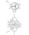
ウォータートラップ110が受容器開口部411内に挿入されていない場合、テザー組立品受容器132は、受容器開口部411を覆うカバーがなく、外部環境からの汚染の影響を受けやすい。図6は、一つの代表的な実施形態による、テザー組立品受容器及びカバーの複数の端面図を提供する。 When the
図6を参照すると、テザー組立品受容器132の端透視図は、ハウジング440、ハウジング440の外周から延びるフランジ441及び442、及び視覚的整列標識421及び422を示す。ハウジング440は、前述のように、受容器開口部411及び受容器開口部411の内表面の向かい合う両側から突出する案内突起415及び416を画成する。 Referring to FIG. 6, an end perspective view of the
加えて、テザー組立品受容器132はカバー460を含む。カバー460は、(ウォータートラップ110が挿入されていない状態で)閉鎖位置で示される。カバー460は、代表的な突出部(lobes)461乃至463並びにスリット464乃至466によって表示される、複数のスリットによって分けられた複数の柔軟な突出部を含む。突出部461乃至463は、それらが自動的に閉鎖するように、弾力のある弾性材料で形成されてもよい。したがって、突出部461乃至463は、ハウジング111の第一の部分210の受容器開口部411の中への挿入によって閉鎖位置から変形してスリット464乃至466の間で互いに分離し、そしてハウジング111の第一の部分210を取り外すことによって閉鎖位置に戻る。閉鎖位置にある突出部461乃至463は、ウォータートラップ110が挿入されていない場合に、例えば汚染物質が受容器開口部411に入ることを防止することによって、テザー組立品受容器132を保護する。図5は3つの突出部461乃至463を図示するが、本教示の範囲から逸脱することなく、如何なる数の突出部であっても含まれ得ることが理解される。 In addition, the
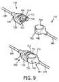
上流側患者インターフェイス接続器142及び下流側患者インターフェイス接続器141のような、互いに付随する様々なラインは、同様に空気接続を必要とする。図7は、一つの代表的な実施形態による、患者インターフェイスライン接続器及び患者付属品接続器の、接続解除状態における上面図及び側面図を提供する。図8は、一つの代表的な実施形態による、患者インターフェイスライン接続器及び患者付属品接続器の、接続状態における上面図及び側面図を提供する。図9は、一つの代表的な実施形態による、患者インターフェイスライン接続器及び患者付属品接続器の、接続解除状態及び接続状態における複数の斜視図を提供する。 Various lines associated with each other, such as the upstream
図7乃至9を参照すると、延長ライン148の上流側患者インターフェイス接続器142が、空気通路145の下流側患者インターフェイス接続器141と共に、接続状態及び接続解除状態で様々に示されている。特に、図示された実施形態において、上流側患者インターフェイス接続器142の構成は上流側ウォータートラップ接続器115の構成と実質的に同一であり、下流側患者インターフェイス接続器141の構成は前述の下流側患者インターフェイス接続器143の構成と実質的に同一である。しかし、本教示の範囲から逸脱することなく、他の接続器構成が組み込まれてもよい。 With reference to FIGS. 7-9, the
図示された実施形態において、上流側患者インターフェイス接続器142は、例えば、ハウジング720、複数のタブ754,755、突出部材756及びシール部材757を有する。ハウジング720は、代表的なフランジ721及び722によって表示され、実質的に向かい合うハウジング720の両側に配置される少なくとも一つのフランジを含む。ハウジング720はまた、少なくとも一つのフランジ721,722に隣接した切欠き部分724を規定する。図示された実施形態において、切欠き部分724は、フランジ721及びフランジ722の間の実質的に“C”形状の切欠きである。上流側患者インターフェイス接続器142の突出部材756は切欠き部分724から延び、そしてシール部材757は突出部材756の周囲を取り囲む。シール部材757は突出部材756の一部として硬質な材料から作られ、下流側患者インターフェイス接続器141は弾性材料で形成されてもよい。一つの他の実施形態において、シール部材757は、下流側患者インターフェイス接続器141の中にぴったりと適合させられるときに圧縮されて空気シールをもたらす、弾性材料で形成されてもよい。シール部材757は、下流側患者インターフェイス接続器141内の開口部の内表面内の対応する溝(図示なし)と連絡してもよい。加えて、図示された実施形態は、代表的な接続器タブ754及び755によって表示され、切欠き部分724の内表面から突出する、複数の接続器タブを含む。接続器タブ754及び755は、例えばスロット765のような、下流側患者インターフェイス接続器141の対応するスロットの中にぴったりと適合するように構成される。接続器タブ754及び755は、上流側患者インターフェイス接続器142が下流側患者インターフェイス接続器141と完全に係合するときに、触知可能な応答をもたらしてもよい。 In the illustrated embodiment, the upstream
下流側患者インターフェイス接続器141はハウジング740を含み、ハウジング740は、ハウジング720によって画成された切欠き部分724と補完的に適合するように構成された、丸い曲線部分741を有する。ハウジング740は、例えば、軟質で順応性の弾性材料で作られてもよい。丸い曲線部分741及び切欠き部分724は、両方とも実質的に“C”形状であり、曲線部分741はフランジ721及び722の間にぴったりと適合する。しかし、本教示の範囲から逸脱することなく、他の形状が組み込まれてもよい。下流側患者インターフェイス接続器141のハウジング740は、複数の肩部分751及び752を更に含む。フランジ721及び722は、下流側患者インターフェイス接続器141が上流側患者インターフェイス接続器142に接続されたときに、肩部分751及び752に対してぴったりとはまる。加えて、下流側患者インターフェイス接続器141は、開口部(図示なし)を含む。開口部は、ハウジング720の切欠き部分724から延びる突出部材756(及びシール部材757)を受容するように構成され、上流側患者インターフェイス接続器142が、下流側患者インターフェイス接続器141内の開口部を経由した空気通路145との連絡のための空気シールをもたらすことを可能にする。また、肩部分751及び752は、スロット765によって表示され、前述のように切欠き部分724の内表面から突出する複数の接続器タブ754及び755をそれぞれ受容するための複数のスロットを画成してもよい。上流側患者インターフェイス接続器142と下流側患者インターフェイス接続器141との間の空気シールを作り出すために必要とされる二次的な構成要素は存在せず、総費用の低減及び接続の信頼性をもたらす。 The downstream
様々な実施形態によれば、副流式呼吸気体分析器のウォーターフィルタ又はウォータートラップは患者インターフェイス組立品から取り外され、交換可能な(使い捨ての)カートリッジ内に入れられる。また、サンプリングチャンバは、患者付属品から交換可能なテザー組立品を経由して気体分析ベンチへ移転されてもよい。サンプル流経路の外に空洞又は余分な内部領域は残らず、死腔が少ない設計を作り出す。この死腔が少ないフィルタカートリッジ及びサンプリングチャンバは、毎回患者インターフェイスが交換されることとは対照的に必要に応じてのみ交換され、患者インターフェイスの総費用を低くする。 According to various embodiments, the side-flow respiratory gas analyzer water filter or water trap is removed from the patient interface assembly and placed in a replaceable (disposable) cartridge. The sampling chamber may also be transferred from the patient accessory to the gas analysis bench via a replaceable tether assembly. No cavity or extra internal area remains outside the sample flow path, creating a design with fewer dead spaces. This low dead space filter cartridge and sampling chamber are replaced only as needed, as opposed to replacing the patient interface each time, reducing the total cost of the patient interface.
本明細書において複数の好ましい実施形態が開示されたが、本発明の構想及び範囲内に留まる多数の変形が可能である。そのような変形は、本出願の詳細な説明、図面及び特許請求の範囲の精査の後に、当業者にとって明らかになるであろう。本発明は、従って、添付の特許請求の範囲の精神及び範囲内を除き、制限されるべきでない。 While several preferred embodiments have been disclosed herein, many variations are possible that remain within the concept and scope of the invention. Such variations will become apparent to those skilled in the art after reviewing the detailed description, drawings, and claims of this application. Accordingly, the invention is not to be restricted except within the spirit and scope of the appended claims.
Claims (20)
Translated fromJapanese第一の部分を有するハウジングであり、前記第一の部分は、テザー組立品受容器に挿入取り付け可能であり、テザーラインを経由して呼吸気体流を供給するために当該装置の分析ベンチへの接続を可能にする、ハウジング、
サンプル流ラインを経由して呼吸気体流を受容するために、患者インターフェイス組立品内の前記サンプル流ラインの下流側患者インターフェイス接続器に取り付け可能である、上流側ウォータートラップ接続器、及び
前記ハウジング内に挿入可能に収容され、呼吸気体流から水分を取り除くように構成されたフィルタ組立品であり、当該フィルタ組立品は、前記テザー組立品受容器内で前記テザーラインに取り付け可能な下流側ウォータートラップ接続器を有し、当該フィルタ組立品は、前記患者インターフェイス組立品とは独立に交換可能である、フィルタ組立品、
を有する、装置。A removable water trap device for removing moisture from a breathing gas stream received from a patient interface assembly and allowing at least one gas in the breathing gas stream to be monitored by an analytical bench, the device Is
A housing having a first portion, the first portion being insertably attachable to a tether assembly receptacle and connected to an analysis bench of the apparatus for supplying respiratory gas flow via a tether line. Housing, which allows connection
An upstream water trap connector, attachable to a patient interface connector downstream of the sample flow line in a patient interface assembly for receiving respiratory gas flow via the sample flow line; and in the housing And a downstream water trap that is attachable to the tether line within the tether assembly receptacle. A filter assembly having a connector, the filter assembly being replaceable independently of the patient interface assembly;
Having a device.
前記第二の部分は、前記ハウジングの前記第一の部分の外表面を超えて延びる少なくとも一つのフランジを規定し、
前記少なくとも一つのフランジは前記ハウジングの回転動作に適している、
請求項4記載の装置。The upstream water trap connector has a second portion of the housing;
The second portion defines at least one flange extending beyond an outer surface of the first portion of the housing;
The at least one flange is suitable for rotational movement of the housing;
The apparatus of claim 4.
前記上流側ウォータートラップ接続器は、前記ハウジングの前記第二の部分の前記切欠き部分から延び、前記下流側患者インターフェイス接続器内の開口部の中に挿入可能な突出部材を更に有する、
請求項6記載の装置。The second portion further defines a notch portion adjacent to the at least one flange;
The upstream water trap connector further includes a protruding member extending from the notched portion of the second portion of the housing and insertable into an opening in the downstream patient interface connector.
The apparatus of claim 6.
請求項7記載の装置。The upstream water trap connector further includes at least one tab extending from an inner surface of the notch portion, the at least one tab being associated with a corresponding slot in the connector of the downstreampatient interface connector. Configured to communicate and the at least one tab provides a tactile response when the upstream water trap connector is fully engaged with the downstreampatient interface connector;
The apparatus of claim 7.
前記ハウジング内に挿入可能に収容されるフィルタ管であり、当該フィルタ管の一端が、前記テザー組立品受容器内の前記テザーラインと共に空気シールをもたらすように構成された前記下流側ウォータートラップ接続器を有する、フィルタ管、
呼吸気体流から水分を吸収するために前記フィルタ管内に配置された、親水性材料、及び
前記親水性材料によって吸収されない呼吸気体流内の水分を遮断するために前記フィルタ管内に配置された、疎水性材料、
を有する、
請求項1記載の装置。The filter assembly is:
The downstream water trap connector, wherein the downstream water trap connector is configured to be insertably received in the housing, wherein one end of the filter tube provides an air seal with the tether line in the tether assembly receptacle. Having a filter tube,
A hydrophilic material disposed in the filter tube to absorb moisture from a breathing gas stream, and a hydrophobic material disposed in the filter tube to block moisture in the breathing gas stream not absorbed by the hydrophilic material Sex material,
Having
The apparatus of claim 1.
患者インターフェイス組立品から受容された呼吸気体流から水分を取り除くための、取り外し可能なウォータートラップ、
呼吸気体流内の少なくとも一つの気体を検出及び分析するための、気体分析ベンチ、及び
前記気体分析ベンチに呼吸気体流を供給するために前記気体分析ベンチと前記患者インターフェイス組立品との間に接続された、テザー組立品であり、当該テザー組立品は、前記ウォータートラップを受容するように構成されたテザー組立品受容器を有する、テザー組立品、
を有し、
前記ウォータートラップは、
前記テザー組立品受容器内の受容器開口部に挿入可能な第一の部分を有し、前記テザー組立品を経由して前記気体分析ベンチへの呼吸気体流の供給を可能にする、ハウジング、
前記ハウジング内に挿入可能であり、呼吸気体流から水分を取り除くように構成されたフィルタ組立品、
水分が取り除かれた状態で呼吸気体を供給するために、前記テザー組立品受容器を経由して前記フィルタ組立品を前記テザー組立品に接続するための、下流側ウォータートラップ接続器、及び
呼吸気体流を受容するために、前記ウォータートラップを前記患者インターフェイス組立品に接続させるための、上流側ウォータートラップ接続器、
を有する、
副流式呼吸気体分析システム。A side flow respiratory gas analysis system,
A removable water trap for removing moisture from the breathing gas stream received from the patient interface assembly;
A gas analysis bench for detecting and analyzing at least one gas in the breathing gas flow; and a connection between the gas analysis bench and the patient interface assembly for providing a breathing gas flow to the gas analysis bench A tether assembly, the tether assembly having a tether assembly receptacle configured to receive the water trap,
Have
The water trap is
A housing having a first portion insertable into a receptacle opening in the tether assembly receptacle, allowing supply of respiratory gas flow to the gas analysis bench via the tether assembly;
A filter assembly insertable into the housing and configured to remove moisture from the breathing gas stream;
A downstream water trap connector for connecting the filter assembly to the tether assembly via the tether assembly receptacle for supplying breathing gas with moisture removed; and breathing gas An upstream water trap connector for connecting the water trap to the patient interface assembly for receiving a flow;
Having
Side flow respiratory gas analysis system.
前記第二の部分は、前記ハウジングの前記第一の部分の外表面を超えて延びる少なくとも一つのフランジを有し且つ前記少なくとも一つのフランジに隣接した切欠き部分を規定し、
前記切欠き部分は、下流側患者インターフェイス組立品接続器の曲線部分と補完的に適合するように構成され、
前記上流側ウォータートラップ接続器は、前記切欠き部分から延び、前記患者インターフェイス組立品の下流側接続器の開口部の中に挿入可能な突出部材を有する、
請求項14記載の副流式呼吸気体分析システム。The housing further comprises a second portion;
The second portion has at least one flange extending beyond an outer surface of the first portion of the housing and defines a notch portion adjacent to the at least one flange;
The notch is configured to complementarily fit with a curved portion of the downstream patient interface assembly connector;
The upstream water trap connector has a protruding member that extends from the notch and is insertable into an opening of the downstream connector of the patient interface assembly.
The side flow type respiratory gas analysis system according to claim 14.
請求項15記載の副流式呼吸気体分析システム。The upstream water trap connector further includes at least one tab extending from an inner surface of the notched portion of the second portion, the at least one tab being the downstream connection of the patient interface assembly. A tactile response when the projecting member is fully engaged with a corresponding opening in the downstream connector of the patient interface assembly. Bring,
The side flow type respiratory gas analysis system according to claim 15.
前記複数の柔軟な突出部は自動的に閉鎖し、前記ハウジングの前記第一の部分が挿入されていない場合に前記複数の柔軟な突出部が閉じて前記受容器開口部を覆う、
請求項13記載の副流式呼吸気体分析システム。The tether assembly further includes a plurality of flexible protrusions that cover the receiver opening, and the first portion of the housing passes through the plurality of flexible protrusions and extends through the receiver opening. Can be inserted inside,
The plurality of flexible protrusions automatically close and the plurality of flexible protrusions close to cover the receiver opening when the first portion of the housing is not inserted;
The side flow type respiratory gas analysis system according to claim 13.
延長ラインであり、当該延長ラインは乾燥器を含む、延長ライン、及び
空気通路、又は鼻カニューレ、鼻−口サンプリングカニューレ又は鼻−口酸素供給鼻カニューレの一つを有する患者インターフェイス、を有し、
下流側患者インターフェイス接続器は、前記延長ラインの下流側端に取り付けられる、
請求項14記載の副流式呼吸気体分析システム。The patient interface assembly is
An extension line, the extension line comprising a dryer, and a patient interface having an air passage, or one of a nasal cannula, nasal-oral sampling cannula or nasal-oral oxygen supply nasal cannula,
A downstream patient interface connector is attached to the downstream end of the extension line;
The side flow type respiratory gas analysis system according to claim 14.
前記上流側患者インターフェイス接続器は、前記延長ラインに取り付けられ且つ前記空気通路上の下流側患者インターフェイス接続器と接続するように構成されており、
前記上流側患者インターフェイス接続器は、
少なくとも一つのフランジ及び前記少なくとも一つのフランジに隣接する切欠き部分を規定するハウジングであり、前記切欠き部分は、前記空気通路の前記下流側患者インターフェイス接続器の曲線部分と補完的に適合するように構成される、ハウジング、及び
前記切欠き部分から延び、前記下流側患者インターフェイス接続器の開口部の中に挿入可能な、突出部材、
を有する、
請求項18記載の副流式呼吸気体分析システム。The patient interface assembly further comprises an upstream patient interface connector;
The upstream patient interface connector is attached to the extension line and configured to connect with a downstream patient interface connector on the air passage;
The upstream patient interface connector is
A housing defining at least one flange and a notch adjacent to the at least one flange, the notch being complementary to a curved portion of the downstream patient interface connector of the air passage. A housing configured to extend from the cutout portion and insertable into an opening of the downstream patient interface connector;
Having
The side-flow type respiratory gas analysis system according to claim 18.
第一の部分及び第二の部分を有するハウジングであり、前記第一の部分は、テザー組立品受容器内の開口部に挿入可能であり、テザーラインを経由して呼吸気体流を供給するために当該ウォータートラップ装置の分析ベンチへの接続を可能にし、当該ハウジングは複数の溝を画成し、前記複数の溝は対応する複数の案内突起とスライド可能に連絡するように構成され、前記複数の案内突起は前記テザー組立品受容器内の開口部の内表面から突出し、前記複数の溝のそれぞれは曲がっており、前記ハウジングの前記第一の部分を前記テザー組立品受容器の中にロックするために、前記ハウジングの回転動作を加えることを必要とする、ハウジング、
前記ハウジング内に挿入可能に収容され、呼吸気体流から水分を取り除くように構成されたフィルタ組立品であり、当該フィルタ組立品は、前記テザー組立品受容器内で前記テザーラインに接続するように構成されたシール先端を有する、フィルタ組立品、及び
前記ハウジングの前記第二の部分を有し、サンプル流ラインを経由して呼吸気体流を受容するために、前記患者インターフェイス組立品の補完的な接続器に取り付け可能な接続器、
を有する、ウォータートラップ装置。A removable water trap device for removing moisture from a breathing gas stream received from a patient interface assembly and allowing at least one gas in the breathing gas stream to be monitored by an analytical bench, the device Is
A housing having a first portion and a second portion, the first portion being insertable into an opening in the tether assembly receptacle for providing a breathing gas flow via a tether line The water trap device can be connected to the analysis bench, the housing defines a plurality of grooves, and the plurality of grooves are configured to slidably communicate with a corresponding plurality of guide protrusions, A guide projection protruding from an inner surface of an opening in the tether assembly receptacle, each of the plurality of grooves being bent to lock the first portion of the housing into the tether assembly receptacle A housing, which requires the rotational movement of the housing to be applied,
A filter assembly housed insertably within the housing and configured to remove moisture from a breathing gas stream, the filter assembly being connected to the tether line within the tether assembly receptacle. A filter assembly having a configured seal tip; and a second assembly of the housing, the complementary portion of the patient interface assembly for receiving respiratory gas flow via a sample flow line A connector that can be attached to the connector
Having a water trap device.
Applications Claiming Priority (3)
| Application Number | Priority Date | Filing Date | Title |
|---|---|---|---|
| US201261683402P | 2012-08-15 | 2012-08-15 | |
| US61/683,402 | 2012-08-15 | ||
| PCT/IB2013/056529WO2014027290A1 (en) | 2012-08-15 | 2013-08-09 | Sidestream respiratory gas sampling system with flexible accessories and removable water trap |
Publications (2)
| Publication Number | Publication Date |
|---|---|
| JP2015526174A JP2015526174A (en) | 2015-09-10 |
| JP6235591B2true JP6235591B2 (en) | 2017-11-22 |
Family
ID=49474646
Family Applications (1)
| Application Number | Title | Priority Date | Filing Date |
|---|---|---|---|
| JP2015527047AExpired - Fee RelatedJP6235591B2 (en) | 2012-08-15 | 2013-08-09 | Sidestream breathing gas sampling system with flexible accessories and removable water trap |
Country Status (5)
| Country | Link |
|---|---|
| US (1) | US9974916B2 (en) |
| EP (1) | EP2885039B1 (en) |
| JP (1) | JP6235591B2 (en) |
| CN (1) | CN104582776B (en) |
| WO (1) | WO2014027290A1 (en) |
Families Citing this family (22)
| Publication number | Priority date | Publication date | Assignee | Title |
|---|---|---|---|---|
| AU2009221772B2 (en) | 2008-03-05 | 2015-01-22 | Solventum Intellectual Properties Company | Dressing and method for applying reduced pressure to and collecting and storing fluid from a tissue site |
| CN103987348B (en) | 2011-12-16 | 2016-05-11 | 凯希特许有限公司 | Releasable Medical Drapes |
| US10940047B2 (en) | 2011-12-16 | 2021-03-09 | Kci Licensing, Inc. | Sealing systems and methods employing a hybrid switchable drape |
| AU2013344686B2 (en) | 2012-11-16 | 2018-06-21 | Solventum Intellectual Properties Company | Medical drape with pattern adhesive layers and method of manufacturing same |
| EP3062751B1 (en)* | 2013-10-30 | 2017-08-09 | KCI Licensing, Inc. | Condensate absorbing and dissipating system |
| US9956120B2 (en) | 2013-10-30 | 2018-05-01 | Kci Licensing, Inc. | Dressing with sealing and retention interface |
| US11026844B2 (en) | 2014-03-03 | 2021-06-08 | Kci Licensing, Inc. | Low profile flexible pressure transmission conduit |
| US20150343163A1 (en)* | 2014-06-02 | 2015-12-03 | Oridion Medical 1987 Ltd. | Breath sampling tube and device |
| JP6640748B2 (en) | 2014-06-05 | 2020-02-05 | ケーシーアイ ライセンシング インコーポレイテッド | Dressing with fluid acquisition and dispensing features |
| WO2016100098A1 (en) | 2014-12-17 | 2016-06-23 | Kci Licensing, Inc. | Dressing with offloading capability |
| US11058842B2 (en) | 2015-08-23 | 2021-07-13 | Pivotal Biotech LLC | Adapter with moisture trap assembly for respiratory circuit |
| EP3741335B1 (en)* | 2015-09-01 | 2023-05-24 | KCI Licensing, Inc. | Dressing with increased apposition force |
| EP3349807B1 (en) | 2015-09-17 | 2021-02-24 | 3M Innovative Properties Company | Hybrid silicone and acrylic adhesive cover for use with wound treatment |
| WO2017063200A1 (en)* | 2015-10-16 | 2017-04-20 | 深圳迈瑞生物医疗电子股份有限公司 | Expiratory end gas measurement system and gas sampling accessories |
| GB201519143D0 (en)* | 2015-10-29 | 2015-12-16 | Gas Measurement Instr Ltd | Gas detection instruments inlet nozzle assembly with integrated particulate filter and hydrophobic filter |
| EP3393352B1 (en)* | 2015-12-21 | 2021-12-08 | Koninklijke Philips N.V. | Sample cells for respired gas sampling and methods of manufacturing same |
| US10820833B2 (en) | 2016-12-09 | 2020-11-03 | Physio-Control, Inc. | Capnograph system further detecting spontaneous patient breaths |
| US20190076057A1 (en)* | 2017-09-13 | 2019-03-14 | Oridion Medical 1987 Ltd. | Filter |
| US11512977B2 (en)* | 2017-12-21 | 2022-11-29 | Mitsubishi Electric Cornoration | Redundant resolver and rotation angle detection device using same |
| US11612846B2 (en)* | 2018-03-12 | 2023-03-28 | Westmed, Inc. | Low dead space laminar flow water filter for side stream CO2 monitoring lines |
| KR102073276B1 (en)* | 2018-06-26 | 2020-02-05 | 경기대학교 산학협력단 | catheter and artificial respirator having the Same |
| DE102019129213A1 (en)* | 2018-11-07 | 2020-05-07 | Löwenstein Medical Technology S.A. | Water trap for a ventilator and respirator with a water trap |
Family Cites Families (11)
| Publication number | Priority date | Publication date | Assignee | Title |
|---|---|---|---|---|
| US4446869A (en) | 1983-03-07 | 1984-05-08 | Trimed, Inc. | Water absorbing trap to protect an infrared exhaled carbon dioxide apnea monitor of a patient's respiration |
| US5131387A (en)* | 1990-05-09 | 1992-07-21 | Marquette Gas Analysis Corp. | Moisture trap |
| IL111162A (en)* | 1994-10-04 | 1998-01-04 | Irad Technologies Ltd | Filtering device utilizable with gas monitors |
| DE19901590C1 (en) | 1999-01-16 | 2000-07-27 | Draeger Medizintech Gmbh | Aqueous condensate trap used in sample gas line of breathing- or anesthetic gas supply apparatus employs microporous PTFE filtration membranes ahead of analyzer, with visible, convenient and reliable condensation collection chamber |
| SE9900351L (en)* | 1999-02-02 | 2000-06-12 | Artema Medical Ab | Liquid separator with holder unit |
| US6390987B1 (en) | 2000-08-03 | 2002-05-21 | Ge Marquette Medical Systems, Inc. | Method and apparatus for separating water and gas in a gas analyzer system |
| US6783573B2 (en)* | 2002-09-27 | 2004-08-31 | Welch Allyn Protocol, Inc. | Gas sampling system |
| US7549316B2 (en)* | 2002-10-08 | 2009-06-23 | Ric Investments, Llc. | Integrated sample cell and filter and system using same |
| US7597733B2 (en) | 2004-01-23 | 2009-10-06 | Ric Investments, Llc | Liquid absorbing filter assembly and system |
| DE102006058164B3 (en)* | 2006-12-09 | 2007-10-31 | Dräger Medical AG & Co. KG | Device used as a monitor for gas analysis and as a respiration device comprises a water trap with a radio frequency marker and a radio frequency acquisition unit having an acquisition region for the marker |
| JP5852587B2 (en)* | 2010-02-22 | 2016-02-03 | クリティケア システムズ インコーポレイテッドCriticare Systems, Inc. | Inline moisture remover |
- 2013
- 2013-08-09USUS14/420,991patent/US9974916B2/enactiveActive
- 2013-08-09EPEP13780195.7Apatent/EP2885039B1/ennot_activeNot-in-force
- 2013-08-09JPJP2015527047Apatent/JP6235591B2/ennot_activeExpired - Fee Related
- 2013-08-09WOPCT/IB2013/056529patent/WO2014027290A1/enactiveApplication Filing
- 2013-08-09CNCN201380043197.0Apatent/CN104582776B/enactiveActive
Also Published As
| Publication number | Publication date |
|---|---|
| US20150217077A1 (en) | 2015-08-06 |
| CN104582776A (en) | 2015-04-29 |
| US9974916B2 (en) | 2018-05-22 |
| EP2885039B1 (en) | 2017-04-26 |
| CN104582776B (en) | 2017-03-08 |
| JP2015526174A (en) | 2015-09-10 |
| WO2014027290A1 (en) | 2014-02-20 |
| EP2885039A1 (en) | 2015-06-24 |
Similar Documents
| Publication | Publication Date | Title |
|---|---|---|
| JP6235591B2 (en) | Sidestream breathing gas sampling system with flexible accessories and removable water trap | |
| JP7134939B2 (en) | Conduit connectors for patient respiratory devices | |
| EP1885460B1 (en) | Fluid drying mechanism | |
| JP5208935B2 (en) | Modular sidestream gas sampling assembly | |
| US7568483B2 (en) | Patient interface with respiratory gas measurement component | |
| US7921846B1 (en) | Heat and moisture filter exchanger and method | |
| US20220031189A1 (en) | Breath sampler | |
| EP1946100A2 (en) | A breath sampling device | |
| US20250261876A1 (en) | Device for measuring a person's ventilation including oxygen-consumption, and a dehumidification cartridge therefor | |
| JP2023096083A (en) | Portable fluid sampling device, system for using the same, and method of making and using the same | |
| US20230330368A1 (en) | Replaceable filter systems for mechanical ventilation | |
| JP4912462B2 (en) | Artificial respiration assembly with carbon dioxide detector | |
| US20160331271A1 (en) | A manual resuscitator and capnograph assembly | |
| GB2622055A (en) | Head wearable air purifier apparatus |
Legal Events
| Date | Code | Title | Description |
|---|---|---|---|
| A521 | Request for written amendment filed | Free format text:JAPANESE INTERMEDIATE CODE: A523 Effective date:20150217 | |
| A621 | Written request for application examination | Free format text:JAPANESE INTERMEDIATE CODE: A621 Effective date:20160808 | |
| A977 | Report on retrieval | Free format text:JAPANESE INTERMEDIATE CODE: A971007 Effective date:20170329 | |
| A131 | Notification of reasons for refusal | Free format text:JAPANESE INTERMEDIATE CODE: A131 Effective date:20170418 | |
| A521 | Request for written amendment filed | Free format text:JAPANESE INTERMEDIATE CODE: A523 Effective date:20170519 | |
| TRDD | Decision of grant or rejection written | ||
| A01 | Written decision to grant a patent or to grant a registration (utility model) | Free format text:JAPANESE INTERMEDIATE CODE: A01 Effective date:20171003 | |
| A61 | First payment of annual fees (during grant procedure) | Free format text:JAPANESE INTERMEDIATE CODE: A61 Effective date:20171026 | |
| R150 | Certificate of patent or registration of utility model | Ref document number:6235591 Country of ref document:JP Free format text:JAPANESE INTERMEDIATE CODE: R150 | |
| R250 | Receipt of annual fees | Free format text:JAPANESE INTERMEDIATE CODE: R250 | |
| R250 | Receipt of annual fees | Free format text:JAPANESE INTERMEDIATE CODE: R250 | |
| R250 | Receipt of annual fees | Free format text:JAPANESE INTERMEDIATE CODE: R250 | |
| R250 | Receipt of annual fees | Free format text:JAPANESE INTERMEDIATE CODE: R250 | |
| LAPS | Cancellation because of no payment of annual fees |