JP6233804B2 - Portable electronic devices - Google Patents
Portable electronic devicesDownload PDFInfo
- Publication number
- JP6233804B2 JP6233804B2JP2013222410AJP2013222410AJP6233804B2JP 6233804 B2JP6233804 B2JP 6233804B2JP 2013222410 AJP2013222410 AJP 2013222410AJP 2013222410 AJP2013222410 AJP 2013222410AJP 6233804 B2JP6233804 B2JP 6233804B2
- Authority
- JP
- Japan
- Prior art keywords
- main body
- apparatus main
- garment
- clothing
- fixture
- Prior art date
- Legal status (The legal status is an assumption and is not a legal conclusion. Google has not performed a legal analysis and makes no representation as to the accuracy of the status listed.)
- Active
Links
- 230000002093peripheral effectEffects0.000claimsdescription37
- 238000001514detection methodMethods0.000claimsdescription23
- 230000004048modificationEffects0.000description7
- 238000012986modificationMethods0.000description7
- 238000005406washingMethods0.000description7
- 229920001971elastomerPolymers0.000description5
- 230000005540biological transmissionEffects0.000description4
- 239000006229carbon blackSubstances0.000description3
- 230000006835compressionEffects0.000description3
- 238000007906compressionMethods0.000description3
- 238000012423maintenanceMethods0.000description3
- 239000000463materialSubstances0.000description3
- 238000005452bendingMethods0.000description2
- 230000007423decreaseEffects0.000description2
- 230000006866deteriorationEffects0.000description2
- 238000010586diagramMethods0.000description2
- 239000000806elastomerSubstances0.000description2
- 238000004519manufacturing processMethods0.000description2
- 125000002066L-histidyl groupChemical group[H]N1C([H])=NC(C([H])([H])[C@](C(=O)[*])([H])N([H])[H])=C1[H]0.000description1
- 239000013013elastic materialSubstances0.000description1
- 230000003203everyday effectEffects0.000description1
- 239000007769metal materialSubstances0.000description1
- 210000003205muscleAnatomy0.000description1
- 229920003225polyurethane elastomerPolymers0.000description1
- 230000001681protective effectEffects0.000description1
- 239000011347resinSubstances0.000description1
- 229920005989resinPolymers0.000description1
- 230000035945sensitivityEffects0.000description1
- 238000000926separation methodMethods0.000description1
- 229920002379silicone rubberPolymers0.000description1
- 210000000707wristAnatomy0.000description1
Images


Classifications
- A—HUMAN NECESSITIES
- A61—MEDICAL OR VETERINARY SCIENCE; HYGIENE
- A61B—DIAGNOSIS; SURGERY; IDENTIFICATION
- A61B5/00—Measuring for diagnostic purposes; Identification of persons
- A61B5/68—Arrangements of detecting, measuring or recording means, e.g. sensors, in relation to patient
- A61B5/6801—Arrangements of detecting, measuring or recording means, e.g. sensors, in relation to patient specially adapted to be attached to or worn on the body surface
- A61B5/6802—Sensor mounted on worn items
- A61B5/6804—Garments; Clothes
- A—HUMAN NECESSITIES
- A41—WEARING APPAREL
- A41D—OUTERWEAR; PROTECTIVE GARMENTS; ACCESSORIES
- A41D1/00—Garments
- A41D1/002—Garments adapted to accommodate electronic equipment
- A—HUMAN NECESSITIES
- A41—WEARING APPAREL
- A41D—OUTERWEAR; PROTECTIVE GARMENTS; ACCESSORIES
- A41D13/00—Professional, industrial or sporting protective garments, e.g. surgeons' gowns or garments protecting against blows or punches
- A41D13/12—Surgeons' or patients' gowns or dresses
- A41D13/1236—Patients' garments
- A41D13/1281—Patients' garments with incorporated means for medical monitoring
- A—HUMAN NECESSITIES
- A61—MEDICAL OR VETERINARY SCIENCE; HYGIENE
- A61B—DIAGNOSIS; SURGERY; IDENTIFICATION
- A61B5/00—Measuring for diagnostic purposes; Identification of persons
- A61B5/0002—Remote monitoring of patients using telemetry, e.g. transmission of vital signals via a communication network
- A61B5/0004—Remote monitoring of patients using telemetry, e.g. transmission of vital signals via a communication network characterised by the type of physiological signal transmitted
- A61B5/0006—ECG or EEG signals
- A—HUMAN NECESSITIES
- A61—MEDICAL OR VETERINARY SCIENCE; HYGIENE
- A61B—DIAGNOSIS; SURGERY; IDENTIFICATION
- A61B5/00—Measuring for diagnostic purposes; Identification of persons
- A61B5/02—Detecting, measuring or recording for evaluating the cardiovascular system, e.g. pulse, heart rate, blood pressure or blood flow
- A61B5/024—Measuring pulse rate or heart rate
- A61B5/02438—Measuring pulse rate or heart rate with portable devices, e.g. worn by the patient
- A—HUMAN NECESSITIES
- A61—MEDICAL OR VETERINARY SCIENCE; HYGIENE
- A61B—DIAGNOSIS; SURGERY; IDENTIFICATION
- A61B5/00—Measuring for diagnostic purposes; Identification of persons
- A61B5/02—Detecting, measuring or recording for evaluating the cardiovascular system, e.g. pulse, heart rate, blood pressure or blood flow
- A61B5/024—Measuring pulse rate or heart rate
- A61B5/0245—Measuring pulse rate or heart rate by using sensing means generating electric signals, i.e. ECG signals
- A—HUMAN NECESSITIES
- A61—MEDICAL OR VETERINARY SCIENCE; HYGIENE
- A61B—DIAGNOSIS; SURGERY; IDENTIFICATION
- A61B5/00—Measuring for diagnostic purposes; Identification of persons
- A61B5/24—Detecting, measuring or recording bioelectric or biomagnetic signals of the body or parts thereof
- A61B5/25—Bioelectric electrodes therefor
- A61B5/251—Means for maintaining electrode contact with the body
- A61B5/256—Wearable electrodes, e.g. having straps or bands
- A—HUMAN NECESSITIES
- A61—MEDICAL OR VETERINARY SCIENCE; HYGIENE
- A61B—DIAGNOSIS; SURGERY; IDENTIFICATION
- A61B5/00—Measuring for diagnostic purposes; Identification of persons
- A61B5/24—Detecting, measuring or recording bioelectric or biomagnetic signals of the body or parts thereof
- A61B5/25—Bioelectric electrodes therefor
- A61B5/279—Bioelectric electrodes therefor specially adapted for particular uses
- A61B5/28—Bioelectric electrodes therefor specially adapted for particular uses for electrocardiography [ECG]
- A61B5/282—Holders for multiple electrodes
- A—HUMAN NECESSITIES
- A61—MEDICAL OR VETERINARY SCIENCE; HYGIENE
- A61B—DIAGNOSIS; SURGERY; IDENTIFICATION
- A61B5/00—Measuring for diagnostic purposes; Identification of persons
- A61B5/68—Arrangements of detecting, measuring or recording means, e.g. sensors, in relation to patient
- A61B5/6801—Arrangements of detecting, measuring or recording means, e.g. sensors, in relation to patient specially adapted to be attached to or worn on the body surface
- A61B5/683—Means for maintaining contact with the body
- A61B5/6831—Straps, bands or harnesses
Landscapes
- Health & Medical Sciences (AREA)
- Life Sciences & Earth Sciences (AREA)
- Engineering & Computer Science (AREA)
- General Health & Medical Sciences (AREA)
- Medical Informatics (AREA)
- Animal Behavior & Ethology (AREA)
- Biophysics (AREA)
- Pathology (AREA)
- Biomedical Technology (AREA)
- Heart & Thoracic Surgery (AREA)
- Veterinary Medicine (AREA)
- Molecular Biology (AREA)
- Surgery (AREA)
- Physics & Mathematics (AREA)
- Public Health (AREA)
- Cardiology (AREA)
- Physiology (AREA)
- Textile Engineering (AREA)
- Signal Processing (AREA)
- Physical Education & Sports Medicine (AREA)
- Computer Networks & Wireless Communication (AREA)
- Measurement And Recording Of Electrical Phenomena And Electrical Characteristics Of The Living Body (AREA)
- Measuring Pulse, Heart Rate, Blood Pressure Or Blood Flow (AREA)
Description
Translated fromJapaneseこの発明は、携帯型電子機器に関するものである。 The present invention relates to a portable electronic device.
身体の生体表面にセンサ電極を取り付け、生体信号を検出する生体情報検出装置が存在する。この種の生体情報検出装置の中には、例えば、心臓の鼓動に伴って発生する心電信号をセンサ電極によって検出し、生体表面から心拍数を計測するものがある。このような生体情報検出装置は、例えば、センサ電極と、センサ電極で検出した心電信号を外部に送信する装置本体(送信部)とを備えたものがある。そして、装置本体から送信された信号を受信した別体の受信ユニットにおいて、心拍数が計測される。 There is a biological information detection device that attaches a sensor electrode to a biological surface of a body and detects a biological signal. Among this type of biological information detection apparatus, for example, there is an apparatus that detects an electrocardiogram signal generated with the heartbeat by a sensor electrode and measures a heart rate from the surface of the living body. Such a biological information detection device includes, for example, a sensor electrode and a device body (transmission unit) that transmits an electrocardiogram signal detected by the sensor electrode to the outside. Then, the heart rate is measured in a separate receiving unit that has received the signal transmitted from the apparatus main body.
センサ電極および装置本体は、ゴム等の伸縮性を有した環状のバンドを用いて使用者の身体に装着される。使用者は、環状のバンドを身体の周囲に沿わせてセンサ電極および装置本体を装着する。これにより、センサ電極が生体表面に押し付けられ、心電信号を検出できる。センサ電極は、心電信号を確実に検出するため、使用中、身体に対し、心電信号の検出に適した所定の位置に保持されている必要がある。
このため、運動中等においても、センサ電極がずれないようにすると、バンドによる締め付け力がきつく、使用者が圧迫感を受けることがある。The sensor electrode and the apparatus main body are attached to the user's body using an annular band having elasticity such as rubber. The user wears the sensor electrode and the apparatus main body along the annular band around the body. Thereby, the sensor electrode is pressed against the surface of the living body, and an electrocardiogram signal can be detected. In order to reliably detect the electrocardiogram signal, the sensor electrode needs to be held at a predetermined position suitable for detecting the electrocardiogram signal with respect to the body during use.
For this reason, even when exercising or the like, if the sensor electrode is not displaced, the tightening force by the band is tight, and the user may feel a sense of pressure.
そこで、例えば特許文献1には、センサ電極を備えたバンドを衣類に一体に取り付けた構成が開示されている。
また、例えば特許文献2には、導電糸を用いることによって、センサ電極が衣類の一部として編み込まれた構成が開示されている。
特許文献1および2のように、センサ電極を衣類に一体に備えることにより、使用者が衣類を身体に装着することで、センサ電極の身体に対する位置が大きくずれることがないとされている。Thus, for example, Patent Document 1 discloses a configuration in which a band including a sensor electrode is integrally attached to clothing.
For example, Patent Document 2 discloses a configuration in which sensor electrodes are knitted as a part of clothing by using conductive yarns.
As in Patent Documents 1 and 2, by providing the sensor electrode integrally with the garment, the position of the sensor electrode with respect to the body is not greatly shifted when the user wears the garment on the body.
しかしながら、特許文献1および2に開示されたような構成にあっては、衣類にセンサ電極を備えているため、衣類の洗濯等によりセンサ電極が劣化しやすい。したがって、生体情報検出装置の寿命の向上という点で改善の余地がある。 However, in the configurations disclosed in Patent Documents 1 and 2, since the clothing is provided with the sensor electrode, the sensor electrode is likely to be deteriorated due to washing of the clothing or the like. Therefore, there is room for improvement in terms of improving the life of the biological information detecting device.
また、センサ電極の位置は、衣類に対するセンサバンドの編み込み位置で決まる。したがって、使用者が、自らの身体に適切なサイズの衣類を選択したとしても、個人差があるため、衣類を身体に着用した状態でセンサ電極が身体に対して適切な位置に配置されるとは限らない。また、センサ電極は、衣類に予め設けられているため、使用者に応じたセンサ電極の位置の調整が行えず、装着位置の自由度が低い。このため、センサ電極の位置が不適切であると、センサ電極における検出性能が低下するおそれがある。また、センサ電極の位置が、使用者が装着した状態で、使用者にとって違和感のある場合もあり、装着性に問題が生じることもある。 The position of the sensor electrode is determined by the position where the sensor band is knitted with respect to the clothing. Therefore, even if the user selects clothing of an appropriate size for his / her body, there are individual differences, and therefore the sensor electrode is placed at an appropriate position with respect to the body with the clothing worn on the body. Is not limited. In addition, since the sensor electrode is provided in the clothing in advance, the position of the sensor electrode cannot be adjusted according to the user, and the degree of freedom of the mounting position is low. For this reason, if the position of the sensor electrode is inappropriate, the detection performance of the sensor electrode may be reduced. In addition, when the position of the sensor electrode is worn by the user, the user may feel uncomfortable, which may cause a problem in wearability.
また、生体情報検出装置に限らず、例えば音楽再生プレーヤや、その他の各種電子機器を、同様にして衣類に備えることも考えられる。このような場合にも、上記したような問題が共通して存在する。 In addition, not only the biological information detection apparatus but also a clothing such as a music player and other various electronic devices can be considered. Even in such a case, there is a common problem as described above.
そこで、本発明は、上記事情に鑑みたものであって、製品寿命を向上させるとともに、任意の位置に装着できる携帯型電子機器を提供することである。 Therefore, the present invention has been made in view of the above circumstances, and it is an object of the present invention to provide a portable electronic device that can improve the product life and can be mounted at an arbitrary position.
上記の課題を解決するため、本発明の携帯型電子機器は、衣類の表裏における一方側に配置され、電子部品が内蔵された装置本体と、前記装置本体とは別体とされて前記衣類の表裏における他方側に配置され、前記衣類の表裏における他方側から前記衣類を前記装置本体との間に挟み込んだ状態で、前記装置本体を前記衣類に対して着脱可能に固定する固定具と、を備え、前記装置本体と、前記装置本体に接続されて生体表面に接触する一対の電極部と、前記一対の電極部に生じる電位差に基づき生体情報を検出する生体情報検出部と、を備えていることを特徴としている。In order to solve the above-described problems, a portable electronic device according to the present invention is disposed on one side of the front and back of a garment, and includes a device main body in which an electronic component is incorporated and a separate device from the device main body. A fixture that is disposed on the other side of the front and back sides and that detachably fixes the apparatus main body to the garment in a state where the garment is sandwiched between the apparatus main body from the other side of the front and back of the garment; Anapparatus body, a pair of electrode parts connected to the apparatus body and in contact with the surface of the living body, and a biological information detection unit for detecting biological information based on a potential difference generated in the pair of electrode parts. It is characterized by that.
本発明によれば、固定具によって装置本体を衣類の任意の位置に着脱自在に固定できる。これにより、使用者は、自身の身体に合わせて装置本体を装着することができるので、装置本体を任意の位置に装着して、所用の機能を発揮させることができる。また、使用者が違和感のない位置に装置本体を装着することができる。
また、固定具による装置本体の固定を解除することで、装置本体および固定具を衣類から取り外し、衣類のみを洗濯することができる。したがって、衣類の交換を自由に行うことができ、装置本体が洗濯によって劣化することもないので、製品寿命を向上させること
ができる。
また、本発明によれば、一対の電極部により、生体表面から生体信号を検出することができる。これにより、衣服に電極を編み込む必要がないので、例えば洗濯等による電極の劣化を防止することができるとともに、検出性能の安定化を図ることができる。According to the present invention, the apparatus main body can be detachably fixed to an arbitrary position of the clothes by the fixing tool. Thereby, since the user can mount | wear with an apparatus main body according to an own body, he can equip an apparatus main body in arbitrary positions and can exhibit a required function. Further, the apparatus main body can be mounted at a position where the user does not feel uncomfortable.
Further, by releasing the fixing of the apparatus main body by the fixing tool, the apparatus main body and the fixing tool can be removed from the clothing, and only the clothing can be washed. Therefore, clothes can be exchanged freely, and the apparatus main body is not deteriorated by washing, so that the product life can be improved.
In addition, according to the present invention, a biological signal can be detected from the biological surface by the pair of electrode portions. Thereby, since it is not necessary to knit the electrode into clothes, for example, deterioration of the electrode due to washing or the like can be prevented, and the detection performance can be stabilized.
また、前記固定具は、前記装置本体の外周部を少なくとも二箇所で固定することを特徴としている。 Moreover, the said fixing tool fixes the outer peripheral part of the said apparatus main body in at least two places, It is characterized by the above-mentioned.
本発明によれば、固定具を衣類に貫通させることなく、簡単に装置本体を固定できる。 According to the present invention, the apparatus main body can be easily fixed without allowing the fixing tool to penetrate the clothing.
また、前記装置本体は、前記固定具が係止される被係止部を備え、前記固定具は、弾性変形可能に形成され、前記被係止部に係止可能な係止部を備えていることを特徴としている。 The apparatus main body includes a locked portion to which the fixing tool is locked, and the fixing tool includes a locking portion that is formed to be elastically deformable and can be locked to the locked portion. It is characterized by being.
本発明によれば、装置本体の被係止部に固定具の係止部を容易に係止させて、装置本体を確実に固定できる。 According to the present invention, the device main body can be reliably fixed by easily locking the locking portion of the fixture to the locked portion of the device main body.
また、前記固定具は、前記装置本体を取り囲む環状に形成されていることを特徴としている。 Further, the fixture is formed in an annular shape surrounding the apparatus main body.
本発明によれば、固定具が簡易な形状であるため、固定具を安価に製造することができる。 According to the present invention, since the fixture has a simple shape, the fixture can be manufactured at low cost.
また、前記固定具の内周面と前記装置本体との間には、前記装置本体を挟んで前記固定具の径方向における少なくとも一方側に、間隙が設けられていることを特徴としている。 Further, a gap is provided between the inner peripheral surface of the fixture and the apparatus main body on at least one side in the radial direction of the fixture with the apparatus main body interposed therebetween.
本発明によれば、固定具の外周面のうち、固定具の内周面と装置本体との間に設けられた間隙に対応する位置を押圧することで、固定具を弾性変形させるとともに、固定具による装置本体の固定を解除することができる。したがって、装置本体を衣類から容易に取り外すことができる。 According to the present invention, the fixing tool is elastically deformed and fixed by pressing a position corresponding to a gap provided between the inner peripheral surface of the fixing tool and the apparatus main body, on the outer peripheral surface of the fixing tool. The device main body can be unlocked by the tool. Therefore, the apparatus main body can be easily detached from the clothing.
また、前記固定具は、前記衣類の表裏における他方側から、前記衣類を介して前記装置本体の少なくとも一部を覆う保護部を備えていることを特徴としている。 Moreover, the said fixing tool is provided with the protection part which covers at least one part of the said apparatus main body through the said clothing from the other side in the front and back of the said clothing.
本発明によれば、固定具により、装置本体や、装置本体を装着した部分の衣類の損傷等を防ぐことができる。 According to the present invention, it is possible to prevent damage to the main body of the apparatus and the clothing to which the apparatus main body is attached by the fixing tool.
また、衣類の表裏における一方側に配置され、電子部品が内蔵された装置本体と、前記装置本体とは別体とされて前記衣類の表裏における他方側に配置され、前記衣類の表裏における他方側から前記衣類を前記装置本体との間に挟み込んだ状態で、前記装置本体を前記衣類に対して着脱可能に固定する固定具と、を備え、前記固定具は、前記装置本体を取り囲む環状に形成されており、前記固定具の内周面と前記装置本体との間には、前記装置本体を挟んで前記固定具の径方向における少なくとも一方側に、間隙が設けられていることを特徴としている。 Also, the apparatus main body that is arranged on one side of the front and back of the garment and in which the electronic component is built, and the apparatus main body are separated from each other and arranged on the other side of the front and back of the garment. A fixture that removably fixes the device body to the clothing in a state where the clothing is sandwiched between the device body, and the fixture is formed in an annular shape surrounding the device body A gap is provided between the inner peripheral surface of the fixture and the apparatus main body on at least one side in the radial direction of the fixture with the apparatus main body interposed therebetween. .
また、前記固定具は、前記衣類の表裏における他方側から、前記衣類を介して前記装置本体の少なくとも一部を覆う保護部を備えていることを特徴としている。 Moreover, the said fixing tool is provided with the protection part which covers at least one part of the said apparatus main body through the said clothing from the other side in the front and back of the said clothing.
本発明によれば、固定具によって装置本体を衣類の任意の位置に着脱自在に固定できる。これにより、使用者は、自身の身体に合わせて装置本体を装着することができるので、装置本体を任意の位置に装着して、所用の機能を発揮させることができる。また、使用者が違和感のない位置に装置本体を装着することができる。
また、固定具による装置本体の固定を解除することで、装置本体および固定具を衣類から取り外し、衣類のみを洗濯することができる。したがって、衣類の交換を自由に行うことができ、装置本体が洗濯によって劣化することもないので、製品寿命を向上させることができる。According to the present invention, the apparatus main body can be detachably fixed to an arbitrary position of the clothes by the fixing tool. Thereby, since the user can mount | wear with an apparatus main body according to an own body, he can equip an apparatus main body in arbitrary positions and can exhibit a required function. Further, the apparatus main body can be mounted at a position where the user does not feel uncomfortable.
Further, by releasing the fixing of the apparatus main body by the fixing tool, the apparatus main body and the fixing tool can be removed from the clothing, and only the clothing can be washed. Therefore, clothes can be exchanged freely, and the apparatus main body is not deteriorated by washing, so that the product life can be improved.
(第一実施形態)
次に、この発明の第一実施形態を図面に基づいて説明する。
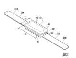
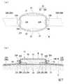
図1は、本発明に係る携帯型電子機器である心拍計測装置を、使用者に取り付けた状態の正面図であり、図2は、心拍計測装置を構成する装置本体の斜視図である。
図1に示すように、心拍計測装置(請求項の「携帯型電子機器」に相当。)10は、使用者Sの生体表面である胸部に装着して心臓の鼓動に伴って発生する心電信号を検出し、この検出した心電信号を無線通信するものである。
心拍計測装置10は、装置本体20と、装置本体20を使用者Sが着用する衣類Wに装着するための固定具30Aと、を備えている。(First embodiment)
Next, a first embodiment of the present invention will be described with reference to the drawings.
FIG. 1 is a front view of a heartbeat measuring device, which is a portable electronic device according to the present invention, attached to a user, and FIG. 2 is a perspective view of a device main body constituting the heartbeat measuring device.
As shown in FIG. 1, a heartbeat measuring device (corresponding to “portable electronic device” in the claims) 10 is attached to a chest that is a biological surface of a user S and is generated as the heart beats. The detected ECG signal is wirelessly communicated.
The
図1および図2に示すように、装置本体20は、平面視で長方形状に形成されたケース21と、このケース21内に設けられている不図示の検出回路基板(請求項の「生体情報検出部」に相当。)と、ケース21の両側に一体的に設けられている一対の心拍検出部22A,22Bと、を備えている。 As shown in FIGS. 1 and 2, the apparatus
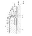
図3は、心拍計測装置を使用者に取り付けた状態の横断面図であり、図4は、図3の要部拡大図である。
図3および図4に示すように、ケース21は、不図示の検出回路基板を収容したケース本体23と、ケース本体23の一面側に装着されたバックプレート24と、を備えている。ケース本体23には、バックプレート24に対向する側において、長方形状のケース本体の長手方向両端部に、心拍検出部22A,22Bの基端部を保持する保持凹部25A,25Bが形成されている。
ケース本体23の外周端面23fには、ケース本体23の中心を挟んで対向する少なくとも二箇所に、固定具30Aを係止させる被係止部として、ケース本体23の内方に向けて凹んだ凹部28A,28B(請求項の「被係止部」に相当。)が形成されている。FIG. 3 is a cross-sectional view of the state in which the heart rate measuring device is attached to the user, and FIG. 4 is an enlarged view of a main part of FIG.
As shown in FIGS. 3 and 4, the
On the outer
検出回路基板は、一対の心拍検出部22A,22Bによって検出された信号に基づいた電気信号を生成する送信回路と、送信回路で生成された電気信号を外部に送出する無線送信部(いずれも不図示)と、を有している。 The detection circuit board includes a transmission circuit that generates an electrical signal based on the signals detected by the pair of
各心拍検出部22A,22Bは、それぞれ帯状の導電エラストマーからなる電極(請求項の「電極部」に相当。)26A,26Bにより構成されている。導電エラストマーとしては、例えば、カーボンブラックを配合した導電シリコンゴムやカーボンブラックを配合した導電ゴム、カーボンブラックを配合した導電ポリウレタンゴム等を用いることができる。
各心拍検出部22A,22Bは、装置本体20を挟んで両側に配置されている。各心拍検出部22A,22Bは、その長手方向一端に形成されている接続部27A,27Bが、ケース本体23の保持凹部25A,25B内に収められた状態で、バックプレート24によりケース本体23との間に挟み込まれて機械的に接続されている。また、電極26A,26Bは、保持凹部25A,25B内で、検出回路基板に電気的に接続されている。
これにより、電極26A,26Bにより検出された信号が検出回路基板に出力されるようになっている。Each of the
Each of the
As a result, signals detected by the
このような装置本体20においては、一対の電極26A,26Bによって心臓の鼓動に伴って発生する心電信号が検出される。装置本体20の不図示の検出回路基板は、一対の電極26A,26Bによって検出された心電信号を無線により外部に出力する。 In such a device
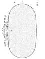
図5は、心拍計測装置を構成する固定具の斜視図である。
図4および図5に示すように、固定具30Aは、装置本体20を取り囲む環状に形成された平面視長円形状のリング状部31と、リング状部31の周方向における二箇所にそれぞれ形成された係止部32A,32Bと、を備えている。FIG. 5 is a perspective view of a fixture constituting the heart rate measuring device.
As shown in FIGS. 4 and 5, the fixing tool 30 </ b> A is formed at two locations in the circumferential direction of the ring-shaped
リング状部31は、装置本体20を構成するケース本体23の外周端面23fに沿うよう、全体の形状が略長円形状とされている。このリング状部31は、例えばゴム系材料や軟質な樹脂材料、金属材料等の弾性変形可能な材料から形成されている。
図5に示すように、リング状部31は、固定具30Aを装置本体20に装着しない状態で、長軸方向に沿う係止部32A,32Bの離間寸法D1がケース本体23の長手方向の外径寸法D3(図2参照)よりも小さく、短軸方向の内径寸法D2が、ケース本体23の短手方向の外径寸法D4(図2参照)よりも大きく形成されている。The entire shape of the ring-shaped
As shown in FIG. 5, in the ring-shaped
係止部32A,32Bは、リング状部31の内周面31fにおいて、長軸方向に対向するように形成されている。図4に示すように、係止部32A,32Bは、それぞれリング状部31の内周面31fから内方に突出するよう形成され、内周面31f側の基部32cから先端部32dに向けて、リング状部31の厚さ方向の寸法が漸次小さくなるよう形成されている。このような係止部32A,32Bは、ケース本体23の外周端面23fに形成された凹部28A,28Bに係止可能とされている。 The locking
また、リング状部31の外周面31gには、係止部32A,32Bが形成された位置に、外周側に向けて突出する突起33A,33Bが形成されている。突起33A,33Bは、リング状部31の外周面31g側の基端部33cから先端部33d側に向かって、リング状部31の厚さ方向の寸法が漸次縮小するよう形成されている。また、突起33A,33Bにおいて、リング状部31の一方の側(本実施形態では使用者S側)を向く面には、滑り止めとなる凹凸34が形成されている。
図5に示すように、さらに、リング状部31の外周面31gには、短軸方向における両端部に、滑り止めとなる凹凸35が形成されている。In addition, on the outer
As shown in FIG. 5, the outer
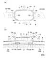
図6は、心拍計測装置を衣類に装着するときの、衣類に対する固定具と装置本体の配置を示す斜視図である。図7は、心拍計測装置を衣類に装着した状態を示す図であり、(a)は正面図であり、(b)は横断面図である。
図6に示すように、上記したような心拍計測装置10は、衣類Wに装着されて使用される。装置本体20は、衣類Wの内側(使用者Sの身体側)に配置される。固定具30Aは、装置本体20が配置された側とは反対側(他方側)となる、衣類Wの外側に配置される。
そして、図3、図4および図7(a),(b)に示すように、固定具30Aは、衣類Wの他方側から衣類Wを装置本体20との間に挟み込んだ状態で、装置本体20の外周部に嵌め込まれる。これによって、装置本体20は、固定具30Aによって衣類Wに着脱可能に固定される。この状態で、衣類Wは、装置本体20の外周面に沿い、ケース本体23の外周端面23fと固定具30Aとの間に挟み込まれる。FIG. 6 is a perspective view showing the arrangement of the fixture and the device main body with respect to the clothing when the heart rate measuring device is attached to the clothing. FIGS. 7A and 7B are diagrams showing a state in which the heart rate measuring device is attached to clothing, where FIG. 7A is a front view and FIG. 7B is a cross-sectional view.
As shown in FIG. 6, the
As shown in FIGS. 3, 4, 7 (a) and 7 (b), the fixture 30 </ b> A has the garment W sandwiched between the garment W from the other side of the garment W and the
また、固定具30Aの係止部32A,32Bは、装置本体20の凹部28A,28Bに係止される。係止部32A,32Bを凹部28A,28Bに係止させるときには、リング状部31の係止部32A,32Bが、ケース本体23の外周端面23fに倣うことで、リング状部31が長軸方向に拡径する方向に弾性変形する。そして、係止部32A,32Bがケース本体23の外周端面23fに沿って移動し、凹部28A,28Bに嵌まり込んで係止される。このとき、固定具30Aは、係止部32A,32Bの離間寸法D1がケース本体23の長手方向の外径寸法D3よりも小さいので、係止部32A,32Bが凹部28A,28Bに入り込んで係止状態が維持される。これにより、固定具30Aが装置本体20から容易には離脱しないようになっている。
このとき、リング状部31は、短軸方向の内径寸法D2(図5参照)が、ケース本体23の短手方向の外径寸法D4(図2参照)よりも大きく形成されている。したがって、固定具30Aの内周面31fと装置本体20との間には、装置本体20を挟んで固定具30Aの短軸方向における両側に、間隙が設けられる。Further, the locking
At this time, the ring-shaped
図8は、心拍計測装置を衣類から取り外すときの状態を示す図であり、(a)は正面図であり、(b)は横断面図である。
また、図8(a),(b)に示すように、固定具30Aを装置本体20から取り外す時には、リング状部31を、凹凸35,35の部分で短軸方向の内側に向けて押圧する。すると、固定具30Aは、リング状部31の短軸方向の内径が小さくなり、その分、長軸方向の外径が大きくなるように弾性変形する。これによって、係止部32A,32Bが凹部28A,28Bから離脱し、係止が解除される。続いて、突起33A,33Bを指で掴み、固定具30Aを衣類Wの表面から引き離す方向に移動させる。これにより、固定具30Aが装置本体20の外周部から外れ、装置本体20及び固定具30Aは、衣類Wへの位置決めが解除される。
なお、固定具30Aを装置本体20から取り外す時には、突起33A,33Bを指で掴み、突起33A,33Bが互いに離間する方向(固定具30Aの長軸方向)に引っ張ることによって、係止部32A,32Bが凹部28A,28Bから離脱させてもよい。FIGS. 8A and 8B are diagrams illustrating a state when the heart rate measuring device is removed from the clothing, in which FIG. 8A is a front view and FIG. 8B is a cross-sectional view.
Further, as shown in FIGS. 8A and 8B, when removing the fixing tool 30 </ b> A from the apparatus
When the fixing
ここで、衣類Wは、伸縮性、弾力性のある素材から形成され、適度に身体を包み込むことによって、筋肉等をサポートする、いわゆるコンプレッションウェアであるのが好ましい。これにより、装置本体20の心拍検出部22A,22Bが使用者Sの身体の表面に密着し、生体信号の検出が高感度に行えるからである。 Here, the garment W is preferably so-called compression wear that is formed of a stretchable and elastic material and supports a muscle or the like by appropriately wrapping the body. This is because the heart
上述した心拍計測装置10は、衣類Wの内側(裏側)に配置され、電子部品が内蔵された装置本体20と、装置本体20とは別体とされて衣類Wの外側(表側)に配置され、衣類Wの外側から衣類Wを装置本体20との間に挟み込んだ状態で、装置本体20を衣類Wに着脱可能に固定する固定具30Aと、を備えている。
このように構成することで、固定具30Aによって装置本体20を衣類Wの任意の位置に着脱自在に固定できる。
したがって、使用者Sの身体に合わせて装置本体20を装着することができる。その結果、装置本体20を任意の位置に装着して、所用の機能を発揮させることができる。また、使用者Sが違和感のない位置に装置本体20を装着することができる。
さらに、衣類Wを洗濯する際には、固定具30Aによる装置本体20の固定を解除することで、装置本体20および固定具30Aを衣類Wから取り外すことができる。したがって、衣類Wの交換を自由に行うことができ、洗濯等に支障が生じることもない。
これにより、心拍計測装置10を装着することによって衣類Wの装着性が低下するのを防ぐことができる。また、心拍計測装置10は、衣類Wとは別体であるために、メンテナンス性、生産性を高めることができ、さらに、製造コストを抑えることができる。また、使用者Sにとっては、心拍計測装置10を連日使用するような場合であっても、心拍計測装置10を複数の衣類W間で付け替えればよい。したがって、心拍計測装置10は一個あればよいため、コスト負担を抑えることができる。The above-described
By comprising in this way, the apparatus
Therefore, the apparatus
Furthermore, when washing the garment W, the
Thereby, it can prevent that the mounting | wearing property of the clothing W falls by mounting | wearing the heart
また、固定具30Aは、装置本体20の外周部を、装置本体20の周方向に間隔を空けた少なくとも二箇所で固定するようにした。
このように構成することで、固定具30Aを衣類Wに貫通させることなく、装置本体20を固定できる。In addition, the fixing tool 30 </ b> A fixes the outer peripheral portion of the apparatus
By comprising in this way, the apparatus
さらに、装置本体20は、固定具30Aが係止される凹部28A,28Bを備え、固定具30Aは、弾性変形可能で、凹部28A,28Bに係止可能な係止部32A,32Bを備えている。
このように構成することで、固定具30Aを弾性変形させて、装置本体20の凹部28A,28Bに固定具30Aの係止部32A,32Bを係止させることによって、装置本体20を容易かつ確実に固定できる。Furthermore, the apparatus
With this configuration, the fixing
また、固定具30Aは、装置本体20を取り囲む環状に形成されている。
このように構成することで、固定具30Aが簡易な形状であるため、固定具30Aを安価に製造することができる。The fixing tool 30 </ b> A is formed in an annular shape surrounding the apparatus
By configuring in this way, the fixing
また、固定具30Aの内周面31fと装置本体20との間には、装置本体20を挟んで固定具30Aの短軸方向における両側に、一対の間隙が設けられている。
これにより、固定具30Aの外周面31gのうち、固定具30Aの内周面31fと装置本体20との間に設けられた間隙に対応する凹凸35を押圧することで、固定具30Aを弾性変形させるとともに、固定具30Aによる装置本体20の固定を解除することができる。したがって、装置本体20を衣類Wから容易に取り外すことができる。A pair of gaps are provided between the inner
Thereby, the fixing
そして、装置本体20は、使用者Sの身体に接触する一対の電極26A,26Bを備えている。
このように構成することで、一対の電極26A,26Bにより、使用者Sから生体信号を検出することができる。これにより、衣類Wに電極26A,26Bを編み込む必要がない。したがって、洗濯による電極劣化がなく、検出性能の安定化を図ることができる。The apparatus
By comprising in this way, a biological signal can be detected from the user S by a pair of
(第二実施形態)
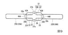
図9は、本発明の第二実施形態における携帯型電子機器である心拍計測装置を示す正面図である。図10は、心拍計測装置を構成する固定具の斜視図である。
次に、本発明にかかる携帯型電子機器の第二実施形態について説明する。
第一実施形態では、固定具30Aが環状に形成されていた(図1参照)。
これに対して、第二実施形態では、図9に示すように、固定具30Bの形状が正面視でクロス状に形成されている点で、第一実施形態とは異なっている。なお、以下に説明する第二の実施形態においては、上記第一の実施形態と共通する構成については図中に同符号を付してその説明を省略する。(Second embodiment)
FIG. 9 is a front view showing a heartbeat measuring device which is a portable electronic device according to the second embodiment of the present invention. FIG. 10 is a perspective view of a fixture constituting the heart rate measuring device.
Next, a second embodiment of the portable electronic device according to the present invention will be described.
In the first embodiment, the fixing
On the other hand, in 2nd embodiment, as shown in FIG. 9, it differs from 1st embodiment by the point by which the shape of the
図9および図10に示すように、心拍計測装置10は、上記第一実施形態と同様の構成を有する装置本体20と、装置本体20を使用者Sが着用する衣類Wに装着するための固定具30Bと、を備えている。
装置本体20を構成するケース本体23の外周端面23fには、ケース本体23の中心を挟んで対向する少なくとも二箇所であって、本実施形態においては、ケース本体23の長手方向における両端部の二箇所に、固定具30Bを係止させる被係止部として、ケース本体23の内方に向けて凹んだ凹部28C,28Dが形成されている。As shown in FIGS. 9 and 10, the
The outer
固定具30Bは、一方向に延びる第一帯状部(請求項の「保護部」に相当。)36と、第一帯状部36の長さ方向中間部において第一帯状部36に直交する第二帯状部(請求項の「保護部」に相当。)37と、を備えたクロス状をなしている。これら第一帯状部36と第二帯状部37とは、固定具30Bを装置本体20に装着した状態で、第一帯状部36が装置本体20の長手方向に沿って延在し、第二帯状部37が装置本体20の短手方向に沿って延在する。
第一帯状部36の両端部36a,36bと、第二帯状部37の両端部37a,37bは、それぞれ、第一帯状部36および第二帯状部37が位置する面に対して一方の側に向けて湾曲している。第一帯状部36の両端部36a,36bの先端部には、それぞれ湾曲方向内側(固定具30Bの中心側)に向けて突出する係止突起(請求項の「係止部」に相当。)42A,42Bが形成されている。さらに、第一帯状部36の両端部36a,36bの先端部には、それぞれ湾曲方向外側に突出する突起44A,44Bが形成されている。突起44A,44Bは、基端部から先端部に向かって、厚さが漸次縮小するよう形成されている。The fixing tool 30 </ b> B includes a first belt-like portion (corresponding to a “protecting portion” in the claims) 36 extending in one direction and a second belt orthogonal to the first belt-
Both
上記したような心拍計測装置10は、使用者Sが着用する衣類Wに装着されて使用される。装置本体20は、衣類Wの内側(使用者Sの身体側)に配置される。固定具30Bは、装置本体20が配置された側とは反対側(他方側)となる、衣類Wの外側に配置される。
そして、固定具30Bは、衣類Wの外側から衣類Wを装置本体20との間に挟み込んだ状態で、装置本体20の外周部に嵌め込まれる。これによって、固定具30Bにより、装置本体20が衣類Wに着脱可能に固定される。この状態で、衣類Wは、装置本体20の外周面に沿い、ケース本体23と固定具30Bの第一帯状部36および第二帯状部37との間に挟み込まれる。The heart
And the fixing
また、第一帯状部36の両端部36a,36bに形成された係止突起42A,42Bは、装置本体20の凹部28C,28Dに係止される。係止突起42A,42Bを凹部28C,28Dに係止させるときには、係止突起42A,42Bが、ケース本体23の外周端面23fに倣うことで、第一帯状部36が弾性変形する。そして、係止突起42A,42Bがケース本体23の外周端面23fに沿って移動し、凹部28C,28Dに嵌まり込んで係止される。
また、固定具30Bにおいて、第一帯状部36と第二帯状部37とが、装置本体20及び衣類Wの外方を向く側を覆っている。これにより、装置本体20および衣類Wが保護される。Further, the locking
Further, in the
固定具30Bを装置本体20から取り外す時には、固定具30Bを、第一帯状部36の両端部36a,36bに形成された突起44A,44Bに指を掛けて引き起こす。すると、第一帯状部36が弾性変形して両端部36a,36bがケース本体23から引き離され、突起44A,44Bが凹部28C,28Dから離脱し、係止が解除される。これにより、固定具30Bが装置本体20の外周部から外れ、装置本体20及び固定具30Bは、衣類Wへの位置決めが解除される。 When the
上述した第二実施形態に係る心拍計測装置10においても、第一実施形態と同様に、心拍計測装置10を装着することによって衣類Wの装着性が低下するのを防ぐことができる。また、心拍計測装置10は、衣類Wとは別体であるために、メンテナンス性、生産性を高めることができ、さらに、製造コストを抑えることができる。また、使用者Sにとっては、心拍計測装置10は一個あればよいため、コスト負担を抑えることができる。
また、固定具30Bは、第一帯状部36と第二帯状部37とが、装置本体20及び衣類Wの外方を向く側の一部を覆っている。これにより、装置本体20および衣類Wが保護され、装置本体20や衣類Wが損傷するのを防ぐことができる。Also in the
In addition, in the fixture 30 </ b> B, the first belt-
(第二実施形態の第一変形例)
次に、上記第二実施形態の各変形例を示す。上記第二実施形態では、固定具30Bを、第一帯状部36と第二帯状部37とが十字状をなすようにしたが、これに限るものではない。
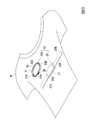
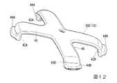
図11は、本発明の第二実施形態の第一変形例としての心拍計測装置を示す正面図である。図12は、心拍計測装置を構成する固定具の斜視図である。図13は、図11のX−X線に沿う断面図である。
例えば、図11から図13に示すように、固定具30Cは、装置本体20に装着した状態で、装置本体20の対角方向に延在する第一帯状部(請求項の「保護部」に相当)45および第二帯状部(保護部)46を備えたX字状をなしている。
そして、第一帯状部45、第二帯状部46の両端部が、ケース本体23に沿うよう、第一帯状部45および第二帯状部46が位置する面に対して一方の側に向けて湾曲している。そして、第一帯状部45、第二帯状部46の両端部には、それぞれ係止突起42A,42B、突起44A,44Bが形成されている。
このような固定具30Cによって衣類Wに固定される装置本体20側には、係止突起42A,42Bに対応した位置に、固定具30Cの係止突起42A,42Bを係止させる被係止部として、ケース本体23の内方に向けて凹んだ凹部28E,28Fが形成されている。(First modification of the second embodiment)
Next, modifications of the second embodiment will be described. In the second embodiment, the fixing
FIG. 11: is a front view which shows the heart rate measuring device as a 1st modification of 2nd embodiment of this invention. FIG. 12 is a perspective view of a fixture constituting the heart rate measuring device. 13 is a cross-sectional view taken along line XX in FIG.
For example, as shown in FIGS. 11 to 13, the fixing tool 30 </ b> C is attached to the apparatus
Then, both end portions of the first belt-
On the side of the apparatus
(第二実施形態の第二変形例)
図14は、本発明の第二実施形態の第二変形例としての心拍計測装置を示す正面図である。図15は、心拍計測装置を構成する固定具の斜視図である。図16は、図14のY−Y線に沿う断面図である。
図14から図16に示すように、固定具30Dは、装置本体20に装着した状態で、装置本体20の中心から、装置本体20の長手方向に沿って互いに隣り合う二つの角部C1,C2に延びる第一帯状部(請求項の「保護部」に相当。)47,第二帯状部(請求項の「保護部」に相当。)48と、角部C1,C2とは反対側の残る二つの角部C3,C4との中間部に向けて延びた第三帯状部(請求項の「保護部」に相当。)49と、を備えたY字状をなしている。
第一帯状部47、第二帯状部48および第三帯状部49の先端部は、第一帯状部47、第二帯状部48および第三帯状部49が位置する面に対して一方の側に向けて湾曲している。そして、第一帯状部47、第二帯状部48および第三帯状部49の先端部には、それぞれ係止突起(請求項の「係止部」に相当。)42A,42B、42Cが形成されている。また、第一帯状部47、第二帯状部48の先端部には、それぞれ突起44A,44Bが形成されている。
このような固定具30Dによって衣類Wに固定される装置本体20側には、係止突起42A,42B、42Cに対応した位置に、固定具30Dを係止させる被係止部として、ケース本体23の内方に向けて凹んだ凹部28G,28H、28Iが形成されている(Second modification of the second embodiment)
FIG. 14 is a front view showing a heartbeat measuring device as a second modified example of the second embodiment of the present invention. FIG. 15 is a perspective view of a fixture constituting the heart rate measuring device. 16 is a cross-sectional view taken along line YY of FIG.
As shown in FIGS. 14 to 16, the fixture 30 </ b> D is mounted on the apparatus
The leading end portions of the first belt-
On the side of the apparatus
(その他の実施形態)
なお、本発明は、図面を参照して説明した上述の各実施形態に限定されるものではなく、その技術的範囲において様々な変形例が考えられる。
例えば、各実施形態においてケース本体23の外周端面23fに形成する凹部28A〜28Iは、ケース本体23の周方向に連続する溝としてもよい。
また、ケース本体23の外周端面23fに形成する凹部28A〜28Iは、固定具30A〜30Dを固定するためだけではなく、例えば、装置本体20を使用者Sの胸部や手首等に装着するためのベルトの端部を保持するための保持部として用いてもよい。(Other embodiments)
The present invention is not limited to the above-described embodiments described with reference to the drawings, and various modifications are conceivable within the technical scope thereof.
For example, the recesses 28 </ b> A to 28 </ b> I formed on the outer
Further, the
また、上記の各実施形態では、ケース本体23側に凹部28A〜28Iを形成し、固定具30A〜30D側に係止部32A,32B、係止突起42A〜42Cを形成したが、これに限定されない。したがって、例えば、ケース本体23の外周端面23f側に被係止部として凸部または周方向に連続する突条を形成し、固定具30A〜30D側に、係止部として凹部または溝を形成してもよい。
また、上記の各実施形態では、固定具30A〜30Dに指を掛けるための突起44A,44Bが設けられていたが、突起44A,44Bの形状は各実施形態に限定されない。
また、突起44A,44Bを設けなくてもよい。ただし、突起44A,44Bを設けることにより、指を突起44A,44Bに掛けて固定具30A〜30Dを弾性変形させるとともに、装置本体20と固定具30A〜30Dとの係合を容易に解除できる点で、各実施形態に優位性がある。In each of the above embodiments, the
Further, in each of the above-described embodiments, the
Further, the
また、上記の各実施形態では、衣類Wとして、使用者Sの上半身に着用されるいわゆるコンプレッションウェアを例に説明をしたが、これに限定されない。したがって、例えば、使用者Sの上半身に着用されるいわゆるコンプレッションウェア以外のシャツでもよいし、使用者Sの下半身に着用されるズボンでもよいし、使用者Sの頭部に着用される帽子であってもよい。 In each of the above embodiments, the so-called compression wear worn on the upper body of the user S is described as an example of the clothing W. However, the present invention is not limited to this. Therefore, for example, a shirt other than the so-called compression wear worn on the upper body of the user S, pants worn on the lower body of the user S, or a hat worn on the head of the user S may be used. May be.
さらに、上記実施形態では、衣類Wの内側に装置本体20を配置し、衣類Wの外側から固定具30A〜30Dによって装置本体20を固定する構成としたが、その表裏を逆転させてもよい。すなわち、衣類Wの外側に装置本体20を配置し、衣類Wの内側から固定具30A〜30Dによって装置本体20を固定する構成としてもよい。 Furthermore, in the said embodiment, although the apparatus
加えて、装置本体20の構成については、何ら限定するものではない。例えば、装置本体20の外形形状は、略長方形状に限らず、各種多角形状や楕円状等、その他さまざまな外形形状とすることができる。
さらに、心拍計測装置10に限らず、携帯型の電子機器であれば、例えば、音楽プレーヤ、カメラ、電話端末、無線通信端末、歩数計、ID(Identification)タグ、GPS(Global Positioning System)装置等、様々な用途の電子機器であってもよい。
また、第一実施形態では、固定具30Aが平面視長円形状に形成されていたが、固定具30Aの形状は平面視長円形状に限定されることはなく、例えば矩形枠状であってもよい。すなわち、第一実施形態の固定具30Aは、弾性変形可能に形成され、かつ装置本体20を取り囲む環状に形成されていればよい。In addition, the configuration of the apparatus
Furthermore, not only the heart
In the first embodiment, the
その他、本発明の趣旨を逸脱しない範囲で、上記した実施の形態における構成要素を周知の構成要素に置き換えることは適宜可能である。 In addition, it is possible to appropriately replace the components in the above-described embodiments with known components without departing from the spirit of the present invention.
10・・・心拍計測装置(携帯型電子機器) 20・・・装置本体 22A,22B・・・心拍検出部 23・・・ケース本体 23f・・・外周端面 26A,26B・・・電極(電極部) 28A〜28I・・・凹部(被係止部) 30A〜30D・・・固定具 31・・・リング状部 32A,32B・・・係止部 36,45,47・・・第一帯状部(保護部) 37,46,48・・・第二帯状部(保護部) 42A〜42C・・・係止突起(係止部) 49・・・第三帯状部(保護部) S・・・使用者 W・・・衣類DESCRIPTION OF
Claims (8)
Translated fromJapanese前記装置本体とは別体とされて前記衣類の表裏における他方側に配置され、前記衣類の表裏における他方側から前記衣類を前記装置本体との間に挟み込んだ状態で、前記装置本体を前記衣類に対して着脱可能に固定する固定具と、
を備え、
前記装置本体と、
前記装置本体に接続されて生体表面に接触する一対の電極部と、
前記一対の電極部に生じる電位差に基づき生体情報を検出する生体情報検出部と、
を備えていることを特徴とする携帯型電子機器。An apparatus body that is arranged on one side of the front and back of the clothing and has electronic components built-in,
The apparatus main body is disposed on the other side of the front and back of the garment and separated from the apparatus main body, and the garment is sandwiched between the apparatus main body and the garment from the other side of the front and back of the garment. A fixing device that is detachably fixed to,
With
The device body;
A pair of electrodes connected to the body of the device and in contact with the surface of the living body;
A biological information detection unit that detects biological information based on a potential difference generated in the pair of electrode units;
A portable electronic device comprising:
前記固定具は、弾性変形可能に形成され、前記被係止部に係止可能な係止部を備えていることを特徴とする請求項1または2に記載の携帯型電子機器。The apparatus main body includes a locked portion to which the fixing tool is locked,
The portable electronic device according to claim 1, wherein the fixing device is formed to be elastically deformable and includes a locking portion that can be locked to the locked portion.
前記装置本体とは別体とされて前記衣類の表裏における他方側に配置され、前記衣類の表裏における他方側から前記衣類を前記装置本体との間に挟み込んだ状態で、前記装置本体を前記衣類に対して着脱可能に固定する固定具と、 The apparatus main body is disposed on the other side of the front and back of the garment and separated from the apparatus main body, and the garment is sandwiched between the apparatus main body and the garment from the other side of the front and back of the garment. A fixture that is detachably fixed to the
を備え、 With
前記固定具は、前記装置本体を取り囲む環状に形成されており、 The fixture is formed in an annular shape surrounding the device body,
前記固定具の内周面と前記装置本体との間には、前記装置本体を挟んで前記固定具の径方向における少なくとも一方側に、間隙が設けられていることを特徴とする携帯型電子機器。 A portable electronic device characterized in that a gap is provided between at least one side in the radial direction of the fixture between the inner peripheral surface of the fixture and the device main body with the device main body interposed therebetween. .
Priority Applications (4)
| Application Number | Priority Date | Filing Date | Title |
|---|---|---|---|
| JP2013222410AJP6233804B2 (en) | 2013-10-25 | 2013-10-25 | Portable electronic devices |
| EP14188625.9AEP2865287B1 (en) | 2013-10-25 | 2014-10-13 | Wearable electronic device |
| US14/518,510US9259182B2 (en) | 2013-10-25 | 2014-10-20 | Portable electronic device |
| CN201410575507.XACN104545876A (en) | 2013-10-25 | 2014-10-24 | Portable electronic device |
Applications Claiming Priority (1)
| Application Number | Priority Date | Filing Date | Title |
|---|---|---|---|
| JP2013222410AJP6233804B2 (en) | 2013-10-25 | 2013-10-25 | Portable electronic devices |
Publications (2)
| Publication Number | Publication Date |
|---|---|
| JP2015083073A JP2015083073A (en) | 2015-04-30 |
| JP6233804B2true JP6233804B2 (en) | 2017-11-22 |
Family
ID=51690915
Family Applications (1)
| Application Number | Title | Priority Date | Filing Date |
|---|---|---|---|
| JP2013222410AActiveJP6233804B2 (en) | 2013-10-25 | 2013-10-25 | Portable electronic devices |
Country Status (4)
| Country | Link |
|---|---|
| US (1) | US9259182B2 (en) |
| EP (1) | EP2865287B1 (en) |
| JP (1) | JP6233804B2 (en) |
| CN (1) | CN104545876A (en) |
Families Citing this family (14)
| Publication number | Priority date | Publication date | Assignee | Title |
|---|---|---|---|---|
| EP2604182B1 (en)* | 2011-09-27 | 2018-12-05 | Under Armour, Inc. | Electronic housing and sensor connection arrangement |
| EP4588433A3 (en) | 2013-11-29 | 2025-07-30 | Ouraring Inc. | Wearable computing device |
| USD777331S1 (en)* | 2014-05-01 | 2017-01-24 | MAD Apparel, Inc. | Electronic module |
| US10660382B2 (en)* | 2015-02-27 | 2020-05-26 | Honeywell Safety Products Usa, Inc. | Apparatus, systems and methods for optimizing and masking compression in a biosensing garment |
| JP6574638B2 (en)* | 2015-05-01 | 2019-09-11 | ケネス フェン シノヅカKenneth Feng Shinozuka | Object attaching / detaching method and object attaching / detaching apparatus |
| US20160367190A1 (en)* | 2015-06-16 | 2016-12-22 | Mondevices Inc. | Method and system of continuous monitoring of body sounds via wearable wireless body sound monitor |
| CN105662337B (en)* | 2015-12-30 | 2018-08-17 | 博迪加科技(北京)有限公司 | A kind of signal processing apparatus and intelligent clothing |
| WO2017125651A1 (en)* | 2016-01-21 | 2017-07-27 | Piq | Assembly comprising an electronic system and a device for attaching said electronic system to a flexible medium |
| JP6514129B2 (en)* | 2016-02-10 | 2019-05-15 | 日本電信電話株式会社 | Wearable electrode |
| US10842205B2 (en) | 2016-10-20 | 2020-11-24 | Nike, Inc. | Apparel thermo-regulatory system |
| USD842481S1 (en) | 2017-01-20 | 2019-03-05 | MAD Apparel, Inc. | Electronic module |
| CN109924959B (en)* | 2017-12-15 | 2022-05-17 | 华为终端有限公司 | Wearable device and control method thereof |
| JP2021020037A (en)* | 2019-07-30 | 2021-02-18 | 美津濃株式会社 | Biological information acquisition garment |
| CN117120965A (en)* | 2021-04-12 | 2023-11-24 | 松下知识产权经营株式会社 | Wearable sensing device |
Family Cites Families (20)
| Publication number | Priority date | Publication date | Assignee | Title |
|---|---|---|---|---|
| US4777954A (en)* | 1986-06-30 | 1988-10-18 | Nepera Inc. | Conductive adhesive medical electrode assemblies |
| US5610877A (en)* | 1995-01-20 | 1997-03-11 | Adams; Kathy S. | Fabric attachable timepiece |
| GB0210889D0 (en) | 2002-05-14 | 2002-06-19 | Koninkl Philips Electronics Nv | Garment and method for producing the same |
| WO2005092177A1 (en)* | 2004-03-22 | 2005-10-06 | Bodymedia, Inc. | Non-invasive temperature monitoring device |
| US7292150B2 (en)* | 2004-04-22 | 2007-11-06 | Mark Shaw | Patient monitoring system |
| US7124447B2 (en)* | 2004-06-29 | 2006-10-24 | Arganese Thomas J | Watch head removably attachable to glove |
| DE102004047650B3 (en)* | 2004-09-30 | 2006-04-13 | W.L. Gore & Associates Gmbh | Garment with inductive coupler and inductive garment interface |
| US7793361B2 (en)* | 2004-11-12 | 2010-09-14 | Nike, Inc. | Article of apparel incorporating a separable electronic device |
| KR100734986B1 (en)* | 2005-09-23 | 2007-07-06 | 한국전자통신연구원 | Bio signal garment |
| US9101264B2 (en)* | 2006-06-15 | 2015-08-11 | Peerbridge Health, Inc. | Wireless electrode arrangement and method for patient monitoring via electrocardiography |
| US7878030B2 (en) | 2006-10-27 | 2011-02-01 | Textronics, Inc. | Wearable article with band portion adapted to include textile-based electrodes and method of making such article |
| CN101138494A (en)* | 2007-10-12 | 2008-03-12 | 杨顺聪 | Magnetic attraction electrode device and portable electrocardiogram measuring system |
| US20110166491A1 (en)* | 2008-09-10 | 2011-07-07 | University Of Tsukuba | Biological signal measuring wearing device and wearable motion assisting apparatus |
| WO2010085688A1 (en)* | 2009-01-22 | 2010-07-29 | Under Armour, Inc. | System and method for monitoring athletic performance |
| US9775561B2 (en)* | 2010-12-23 | 2017-10-03 | Covidien Lp | System method and device for monitoring physiological parameters of a person |
| US8909318B2 (en)* | 2011-03-18 | 2014-12-09 | Nike Inc. | Apparel for physiological telemetry during athletics |
| EP2604182B1 (en)* | 2011-09-27 | 2018-12-05 | Under Armour, Inc. | Electronic housing and sensor connection arrangement |
| JP5441977B2 (en)* | 2011-10-13 | 2014-03-12 | セイコーインスツル株式会社 | Biological information detection device |
| CN103263293B (en)* | 2013-03-08 | 2016-08-10 | 蒋琼橙 | A kind of Detachable body surface fixing device |
| US9402429B2 (en)* | 2013-03-14 | 2016-08-02 | Nike, Inc. | Telemetrically enhanced athletic apparel |
- 2013
- 2013-10-25JPJP2013222410Apatent/JP6233804B2/enactiveActive
- 2014
- 2014-10-13EPEP14188625.9Apatent/EP2865287B1/enactiveActive
- 2014-10-20USUS14/518,510patent/US9259182B2/enactiveActive
- 2014-10-24CNCN201410575507.XApatent/CN104545876A/enactivePending
Also Published As
| Publication number | Publication date |
|---|---|
| US20150119676A1 (en) | 2015-04-30 |
| JP2015083073A (en) | 2015-04-30 |
| CN104545876A (en) | 2015-04-29 |
| EP2865287A1 (en) | 2015-04-29 |
| EP2865287B1 (en) | 2017-02-22 |
| US9259182B2 (en) | 2016-02-16 |
Similar Documents
| Publication | Publication Date | Title |
|---|---|---|
| JP6233804B2 (en) | Portable electronic devices | |
| JP5441977B2 (en) | Biological information detection device | |
| KR100895300B1 (en) | Biosignal garments and biosignal processing systems | |
| US10433782B2 (en) | Electronic button for smart garments | |
| US11259580B2 (en) | Health monitoring garment and system | |
| JP5580801B2 (en) | Biological information detection device | |
| JP5843005B2 (en) | ECG signal measuring apparatus and ECG signal measuring method | |
| KR101573043B1 (en) | Smart clothes having double layer | |
| US10034500B2 (en) | Garment | |
| US20150201856A1 (en) | Electrode and measuring device for acquiring biomedical vital parameters | |
| EP2865327B1 (en) | Heart rate measuring device | |
| KR101675577B1 (en) | sensor module for sensing stiffness of muscle | |
| WO2017109520A1 (en) | A wearable heart rate and activity monitor system | |
| KR102748989B1 (en) | Ring inner diameter adjusting device and Ring-shaped bio-signal detection device including the same | |
| KR20250079713A (en) | Ring-shaped vital signs collection device with optimized rib structure | |
| JP2014033871A (en) | Organism information detector | |
| JP7455405B2 (en) | wearable equipment | |
| CN211750446U (en) | Orthopedic rehabilitation belt with wrist joint provided with shaping sleeve | |
| CN107920756B (en) | Pulse wave detection device | |
| JP2022182637A5 (en) | ||
| US20170354375A1 (en) | Wearable device and electric signal detection unit thereof | |
| JP2016146859A (en) | Electrocardiographic or cardiac beat information acquisition device | |
| JP2006346308A (en) | Device for holding electrode of electrocardiogram |
Legal Events
| Date | Code | Title | Description |
|---|---|---|---|
| A621 | Written request for application examination | Free format text:JAPANESE INTERMEDIATE CODE: A621 Effective date:20160805 | |
| A977 | Report on retrieval | Free format text:JAPANESE INTERMEDIATE CODE: A971007 Effective date:20170728 | |
| A131 | Notification of reasons for refusal | Free format text:JAPANESE INTERMEDIATE CODE: A131 Effective date:20170801 | |
| A521 | Request for written amendment filed | Free format text:JAPANESE INTERMEDIATE CODE: A523 Effective date:20170921 | |
| TRDD | Decision of grant or rejection written | ||
| A01 | Written decision to grant a patent or to grant a registration (utility model) | Free format text:JAPANESE INTERMEDIATE CODE: A01 Effective date:20171003 | |
| RD03 | Notification of appointment of power of attorney | Free format text:JAPANESE INTERMEDIATE CODE: A7423 Effective date:20171017 | |
| A61 | First payment of annual fees (during grant procedure) | Free format text:JAPANESE INTERMEDIATE CODE: A61 Effective date:20171017 | |
| R150 | Certificate of patent or registration of utility model | Ref document number:6233804 Country of ref document:JP Free format text:JAPANESE INTERMEDIATE CODE: R150 | |
| R250 | Receipt of annual fees | Free format text:JAPANESE INTERMEDIATE CODE: R250 | |
| R250 | Receipt of annual fees | Free format text:JAPANESE INTERMEDIATE CODE: R250 | |
| R250 | Receipt of annual fees | Free format text:JAPANESE INTERMEDIATE CODE: R250 | |
| R250 | Receipt of annual fees | Free format text:JAPANESE INTERMEDIATE CODE: R250 | |
| S111 | Request for change of ownership or part of ownership | Free format text:JAPANESE INTERMEDIATE CODE: R313113 | |
| R250 | Receipt of annual fees | Free format text:JAPANESE INTERMEDIATE CODE: R250 | |
| R350 | Written notification of registration of transfer | Free format text:JAPANESE INTERMEDIATE CODE: R350 |