JP6227652B2 - System, method, and computer-accessible medium for fabricating a miniature endoscope using soft lithography - Google Patents
System, method, and computer-accessible medium for fabricating a miniature endoscope using soft lithographyDownload PDFInfo
- Publication number
- JP6227652B2 JP6227652B2JP2015528618AJP2015528618AJP6227652B2JP 6227652 B2JP6227652 B2JP 6227652B2JP 2015528618 AJP2015528618 AJP 2015528618AJP 2015528618 AJP2015528618 AJP 2015528618AJP 6227652 B2JP6227652 B2JP 6227652B2
- Authority
- JP
- Japan
- Prior art keywords
- grating
- elastomeric material
- exemplary
- diffractive
- adhesive formulation
- Prior art date
- Legal status (The legal status is an assumption and is not a legal conclusion. Google has not performed a legal analysis and makes no representation as to the accuracy of the status listed.)
- Expired - Fee Related
Links
Images


Classifications
- B—PERFORMING OPERATIONS; TRANSPORTING
- B29—WORKING OF PLASTICS; WORKING OF SUBSTANCES IN A PLASTIC STATE IN GENERAL
- B29D—PRODUCING PARTICULAR ARTICLES FROM PLASTICS OR FROM SUBSTANCES IN A PLASTIC STATE
- B29D11/00—Producing optical elements, e.g. lenses or prisms
- B29D11/00663—Production of light guides
- B—PERFORMING OPERATIONS; TRANSPORTING
- B29—WORKING OF PLASTICS; WORKING OF SUBSTANCES IN A PLASTIC STATE IN GENERAL
- B29D—PRODUCING PARTICULAR ARTICLES FROM PLASTICS OR FROM SUBSTANCES IN A PLASTIC STATE
- B29D11/00—Producing optical elements, e.g. lenses or prisms
- B29D11/0074—Production of other optical elements not provided for in B29D11/00009- B29D11/0073
- B29D11/00769—Producing diffraction gratings
- B—PERFORMING OPERATIONS; TRANSPORTING
- B32—LAYERED PRODUCTS
- B32B—LAYERED PRODUCTS, i.e. PRODUCTS BUILT-UP OF STRATA OF FLAT OR NON-FLAT, e.g. CELLULAR OR HONEYCOMB, FORM
- B32B37/00—Methods or apparatus for laminating, e.g. by curing or by ultrasonic bonding
- B32B37/14—Methods or apparatus for laminating, e.g. by curing or by ultrasonic bonding characterised by the properties of the layers
- B32B37/16—Methods or apparatus for laminating, e.g. by curing or by ultrasonic bonding characterised by the properties of the layers with all layers existing as coherent layers before laminating
- B32B37/18—Methods or apparatus for laminating, e.g. by curing or by ultrasonic bonding characterised by the properties of the layers with all layers existing as coherent layers before laminating involving the assembly of discrete sheets or panels only
- B—PERFORMING OPERATIONS; TRANSPORTING
- B32—LAYERED PRODUCTS
- B32B—LAYERED PRODUCTS, i.e. PRODUCTS BUILT-UP OF STRATA OF FLAT OR NON-FLAT, e.g. CELLULAR OR HONEYCOMB, FORM
- B32B38/00—Ancillary operations in connection with laminating processes
- B32B38/0008—Electrical discharge treatment, e.g. corona, plasma treatment; wave energy or particle radiation
- B—PERFORMING OPERATIONS; TRANSPORTING
- B32—LAYERED PRODUCTS
- B32B—LAYERED PRODUCTS, i.e. PRODUCTS BUILT-UP OF STRATA OF FLAT OR NON-FLAT, e.g. CELLULAR OR HONEYCOMB, FORM
- B32B38/00—Ancillary operations in connection with laminating processes
- B32B38/10—Removing layers, or parts of layers, mechanically or chemically
- G—PHYSICS
- G02—OPTICS
- G02B—OPTICAL ELEMENTS, SYSTEMS OR APPARATUS
- G02B23/00—Telescopes, e.g. binoculars; Periscopes; Instruments for viewing the inside of hollow bodies; Viewfinders; Optical aiming or sighting devices
- G02B23/24—Instruments or systems for viewing the inside of hollow bodies, e.g. fibrescopes
- G02B23/2407—Optical details
- G02B23/2423—Optical details of the distal end
- G—PHYSICS
- G02—OPTICS
- G02B—OPTICAL ELEMENTS, SYSTEMS OR APPARATUS
- G02B23/00—Telescopes, e.g. binoculars; Periscopes; Instruments for viewing the inside of hollow bodies; Viewfinders; Optical aiming or sighting devices
- G02B23/24—Instruments or systems for viewing the inside of hollow bodies, e.g. fibrescopes
- G02B23/2407—Optical details
- G02B23/2461—Illumination
- G02B23/2469—Illumination using optical fibres
- G—PHYSICS
- G02—OPTICS
- G02B—OPTICAL ELEMENTS, SYSTEMS OR APPARATUS
- G02B23/00—Telescopes, e.g. binoculars; Periscopes; Instruments for viewing the inside of hollow bodies; Viewfinders; Optical aiming or sighting devices
- G02B23/24—Instruments or systems for viewing the inside of hollow bodies, e.g. fibrescopes
- G02B23/26—Instruments or systems for viewing the inside of hollow bodies, e.g. fibrescopes using light guides
- G—PHYSICS
- G02—OPTICS
- G02B—OPTICAL ELEMENTS, SYSTEMS OR APPARATUS
- G02B3/00—Simple or compound lenses
- G02B3/0087—Simple or compound lenses with index gradient
- G—PHYSICS
- G02—OPTICS
- G02B—OPTICAL ELEMENTS, SYSTEMS OR APPARATUS
- G02B5/00—Optical elements other than lenses
- G02B5/18—Diffraction gratings
- G02B5/1847—Manufacturing methods
- G02B5/1852—Manufacturing methods using mechanical means, e.g. ruling with diamond tool, moulding
- G—PHYSICS
- G02—OPTICS
- G02B—OPTICAL ELEMENTS, SYSTEMS OR APPARATUS
- G02B5/00—Optical elements other than lenses
- G02B5/18—Diffraction gratings
- G02B5/1847—Manufacturing methods
- G02B5/1857—Manufacturing methods using exposure or etching means, e.g. holography, photolithography, exposure to electron or ion beams
- G—PHYSICS
- G02—OPTICS
- G02B—OPTICAL ELEMENTS, SYSTEMS OR APPARATUS
- G02B6/00—Light guides; Structural details of arrangements comprising light guides and other optical elements, e.g. couplings
- G02B6/24—Coupling light guides
- G02B6/26—Optical coupling means
- G02B6/34—Optical coupling means utilising prism or grating
- B—PERFORMING OPERATIONS; TRANSPORTING
- B32—LAYERED PRODUCTS
- B32B—LAYERED PRODUCTS, i.e. PRODUCTS BUILT-UP OF STRATA OF FLAT OR NON-FLAT, e.g. CELLULAR OR HONEYCOMB, FORM
- B32B2307/00—Properties of the layers or laminate
- B32B2307/40—Properties of the layers or laminate having particular optical properties
- B32B2307/412—Transparent
- B—PERFORMING OPERATIONS; TRANSPORTING
- B32—LAYERED PRODUCTS
- B32B—LAYERED PRODUCTS, i.e. PRODUCTS BUILT-UP OF STRATA OF FLAT OR NON-FLAT, e.g. CELLULAR OR HONEYCOMB, FORM
- B32B2551/00—Optical elements
- Y—GENERAL TAGGING OF NEW TECHNOLOGICAL DEVELOPMENTS; GENERAL TAGGING OF CROSS-SECTIONAL TECHNOLOGIES SPANNING OVER SEVERAL SECTIONS OF THE IPC; TECHNICAL SUBJECTS COVERED BY FORMER USPC CROSS-REFERENCE ART COLLECTIONS [XRACs] AND DIGESTS
- Y10—TECHNICAL SUBJECTS COVERED BY FORMER USPC
- Y10T—TECHNICAL SUBJECTS COVERED BY FORMER US CLASSIFICATION
- Y10T156/00—Adhesive bonding and miscellaneous chemical manufacture
- Y10T156/10—Methods of surface bonding and/or assembly therefor
Landscapes
- Physics & Mathematics (AREA)
- Engineering & Computer Science (AREA)
- General Physics & Mathematics (AREA)
- Optics & Photonics (AREA)
- Manufacturing & Machinery (AREA)
- Astronomy & Astrophysics (AREA)
- Mechanical Engineering (AREA)
- Health & Medical Sciences (AREA)
- Ophthalmology & Optometry (AREA)
- Thermal Sciences (AREA)
- Plasma & Fusion (AREA)
- Diffracting Gratings Or Hologram Optical Elements (AREA)
- Endoscopes (AREA)
- Instruments For Viewing The Inside Of Hollow Bodies (AREA)
- Lenses (AREA)
Description
Translated fromJapanese [関連出願についての相互参照]
本願は、2012年8月22日出願の米国仮特許出願第61/692,117号および2013年3月13日出願の米国仮特許出願第61/779,671号に関し、そしてその優先権を主張する。そしてその開示内容は、全体として参照により本明細書に組み込まれる。[Cross-reference for related applications]
This application relates to and claims priority to US Provisional Patent Application No. 61 / 692,117 filed on August 22, 2012 and US Provisional Patent Application No. 61 / 779,671 filed on March 13, 2013. To do. The disclosure of which is incorporated herein by reference in its entirety.
[技術分野]
本開示は、概して、ミニチュア顕微鏡の製作に関し、そして特に、ソフトリソグラフィを用いてミニチュア内視鏡を製作するための、そして最少侵襲的画像形成および画像に導かれる治療のための、例示的なシステム、方法、およびコンピュータ・アクセス可能媒体に関する。[Technical field]
The present disclosure relates generally to the fabrication of miniature microscopes, and in particular to exemplary systems for fabricating miniature endoscopes using soft lithography and for minimally invasive imaging and image-guided therapy. , Methods, and computer-accessible media.
スペクトルでコード化された内視鏡検査(「SEE」)は、サブミリメートルの直径のプローブを通して高解像度画像診断を行うことができるミニチュア内視鏡検査技術である。SEEについては、ブロードバンド光は、サンプル上の分散したスペクトルを生じて、ファイバの先端で格子によって回折される。サンプルから反射される光は、分光計を用いて検出される。そして、各分解可能な波長は、サンプルの異なる位置からの反射率に対応する。以前、SEE手順は、350μmの直径のプローブを用いて行われた。そしてそれは、2次元のおよび3次元の高品質の画像を生成した。SEEプローブを製作するための技術的挑戦の1つは、高い回折効率を有するサブミリメートルの透過回折格子を作ること、および、ミニチュア格子をプローブ内の他の光学コンポーネントと正確にアセンブルすること、であった。 Spectrum-encoded endoscopy (“SEE”) is a miniature endoscopy technique that can perform high-resolution imaging through submillimeter diameter probes. For SEE, broadband light produces a dispersed spectrum on the sample and is diffracted by the grating at the tip of the fiber. Light reflected from the sample is detected using a spectrometer. Each resolvable wavelength then corresponds to the reflectance from a different location on the sample. Previously, the SEE procedure was performed using a 350 μm diameter probe. And it produced 2D and 3D high quality images. One of the technical challenges for fabricating SEE probes is to create a submillimeter transmission grating with high diffraction efficiency and to assemble the miniature grating accurately with other optical components in the probe. there were.
したがって、SEEプローブの上記の製作を改善すること、および、従来のデバイスの不足の少なくともいくらかを克服することは、必要でもよい。 Therefore, it may be necessary to improve the above fabrication of the SEE probe and overcome at least some of the deficiencies of conventional devices.
したがって、そのような例示的必要を扱うために、本開示の例示的実施形態によるソフトリソグラフィを用いてミニチュア内視鏡を製作するためのシステム、方法、およびコンピュータ・アクセス可能媒体は、提供されることができる。1つの例示的実施形態によれば、方法、システム、およびコンピュータ・アクセス可能媒体は、SEE画像光学系上のミニチュア回折格子の製作を含む、ソフトリソグラフィを用いてSEEプローブを製作するために提供されることができる。 Accordingly, to address such exemplary needs, systems, methods, and computer-accessible media for fabricating a miniature endoscope using soft lithography according to exemplary embodiments of the present disclosure are provided. be able to. According to one exemplary embodiment, a method, system, and computer-accessible medium are provided for fabricating SEE probes using soft lithography, including fabrication of miniature diffraction gratings on SEE imaging optics. Can.
1つの例示的実施形態において、ミニチュア格子は、最初にPDMS格子マスターパターンを作り、次いで、ミニチュア画像形成レンズ上に格子パターンを複製することによって提供されることができる。この方法によって製作される格子で最小直径は、直径0.1mm未満の超ミニチュアSEEプローブの製作を有効にする、画像形成レンズの最小サイズによって制限されるだけである。そして、ミニチュア格子は、最終的なデバイスを安価にしている紫外光硬化エポキシ、ポリウレタン、または他の低コスト・ポリマーによって容易に製作されることができる。 In one exemplary embodiment, a miniature grating can be provided by first creating a PDMS grating master pattern and then replicating the grating pattern on the miniature imaging lens. The minimum diameter in a grating produced by this method is only limited by the minimum size of the imaging lens that enables the production of ultra-miniature SEE probes with a diameter of less than 0.1 mm. And miniature gratings can be easily fabricated with ultraviolet light curable epoxies, polyurethanes, or other low cost polymers that make the final device inexpensive.
したがって、本開示の特定の例示的実施形態によれば、光学配置において回折する回折構成が提供されることができるための例示的な方法およびシステムは、示されることができる。例えば、エラストマー材料は、少なくとも1つのパターン化した表面を有して提供されることができる。エラストマー材料は、プレポリマー接着剤配合物を用いて導波路配置の少なくとも一部と接続されることができる。さらに、エラストマーモールドの構造または少なくとも1つの特徴を少なくともほぼ複製する回折構成を形成するように、プレポリマー接着剤配合物は、重合させられることがありえる。 Thus, according to certain exemplary embodiments of the present disclosure, exemplary methods and systems for providing a diffractive configuration that diffracts in an optical arrangement can be presented. For example, the elastomeric material can be provided having at least one patterned surface. The elastomeric material can be connected to at least a portion of the waveguide arrangement using a prepolymer adhesive formulation. Further, the prepolymer adhesive formulation can be polymerized so as to form a diffractive configuration that at least substantially replicates the structure or at least one feature of the elastomer mold.
例えば、本開示の1つの例示的実施形態において、回折構成は、格子であることができる。エラストマー材料は、光学配置から取り除かれることができる。光学配置は、回折構成との光通信において少なくとも1つのレンズを含むことができる。エラストマー材料は、堅いエラストマーコンポーネントおよび柔らかいバックサポートを含むことができる。パターン化した表面を形成するためにエラストマースタンプを使用することによって、エラストマー材料は、提供されることができる。プレポリマー接着剤配合物は、重合させるためにプレポリマー接着剤配合物に少なくとも1つの電磁放射線を適用することによって、重合させられることができる。電磁放射線は、導波路配置を介して提供されることができる。プレポリマー接着剤配合物は、1.3〜1.7の屈折率を有することができる。回折構成は、1mm未満の直径または横断面を有することができる。格子は、(i)1000ライン/mmよりも大きい溝密度および(ii)1よりも大きい溝アスペクト比を有することができる。格子は、70%よりも大きい回折効率を有することができる。回折構成は、少なくとも1つのレンズ要素を有することができる。光学配置は、GRINレンズを含むことができる。 For example, in one exemplary embodiment of the present disclosure, the diffractive configuration can be a grating. The elastomeric material can be removed from the optical arrangement. The optical arrangement can include at least one lens in optical communication with the diffractive configuration. The elastomeric material can include a rigid elastomeric component and a soft back support. By using an elastomeric stamp to form a patterned surface, an elastomeric material can be provided. The prepolymer adhesive formulation can be polymerized by applying at least one electromagnetic radiation to the prepolymer adhesive formulation to polymerize. Electromagnetic radiation can be provided via a waveguide arrangement. The prepolymer adhesive formulation can have a refractive index of 1.3 to 1.7. The diffractive configuration can have a diameter or cross section of less than 1 mm. The grating may have (i) a groove density greater than 1000 lines / mm and (ii) a groove aspect ratio greater than 1. The grating can have a diffraction efficiency greater than 70%. The diffractive configuration can have at least one lens element. The optical arrangement can include a GRIN lens.
本開示のこれらのそして他の目的、特徴および利点は、添付の図面および請求項を参照しながら、本開示の例示的実施形態の以下の詳細な説明を読み込むと、即座に明らかになる。 These and other objects, features and advantages of the present disclosure will become readily apparent upon reading the following detailed description of exemplary embodiments of the present disclosure with reference to the accompanying drawings and claims.
本開示のさらなる目的、特徴および利点は、本開示の例示的実施形態の図示の実施形態、結果および/または特徴を示す添付の図に関連してなされる以下の詳述から明らかになる。 Further objects, features and advantages of the present disclosure will become apparent from the following detailed description, taken in conjunction with the accompanying drawings illustrating exemplary embodiments, results and / or features of exemplary embodiments of the present disclosure.
図面の全体を通じて、同一の参照番号および文字は、特に明記しない限り、図示の実施形態の同様の特徴、要素、コンポーネント、または部分を示すために用いる。類似の特徴は、したがって、同一の参照番号によって記載されてよい。そしてそれは、明示的に述べられない限り、異なる実施形態間での特徴の交換がされうることを当業者の読者に示す。さらに、本開示が図に関してここで詳述されるとはいえ、それは図示の実施形態に関連してそうされるのであり、図示される特定の実施形態によって制限されない。添付の請求の範囲により定義される本開示の真の範囲および精神を逸脱しない範囲で、記載された実施形態に改変および変更がなされることができることは、意図される。 Throughout the drawings, the same reference numerals and letters are used to indicate similar features, elements, components, or parts of the illustrated embodiments unless otherwise specified. Similar features may therefore be described by the same reference number. And it indicates to the reader of those skilled in the art that features can be exchanged between different embodiments unless explicitly stated. Further, although the present disclosure is described in detail herein with respect to the figures, it is done in connection with the illustrated embodiment and is not limited by the particular embodiment illustrated. It is intended that modifications and changes may be made to the described embodiments without departing from the true scope and spirit of the present disclosure as defined by the appended claims.
SEEプローブの例示的実施形態の概念図は、本開示の例示的実施形態による図1に示される。この例示的なSEEプローブは、光ファイバ100、集束レンズ110、および回折格子120を含むことができる。図1に示すように、ブロードバンド光または紫外光130は、サンプル140の横の面に沿って分散されることができる。 A conceptual diagram of an exemplary embodiment of a SEE probe is shown in FIG. 1 according to an exemplary embodiment of the present disclosure. This exemplary SEE probe can include an
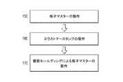
本開示の1つの例示的実施形態において、回折格子120は、図2に示すように、本開示の例示的実施形態による例示的プロセスに基づいて製作されることができる。この例示的プロセスにおいて、格子パターンを有するマスターは、製作されることができる(手順150)。格子マスターは、例えば、電子ビーム・リソグラフィ、フォトリソグラフィ、干渉リソグラフィ、ナノエンボシング、ナノインプリント、または反応性イオンエッチングを含む、さまざまな方法によって作られることができる。格子マスターの例示的なジオメトリは、作業スペクトルでの高い回折効率を提供するために、数値シミュレーションによって決定されることができる。例えば、400〜700ナノメートルの作業スペクトル用に、格子材料の屈折率が約1.47であるときに85%の回折効率を提供するために、格子は、1379ライン/mmの溝密度および1μmの溝深さを有することができる。格子マスターは、エッチングされた石英ガラス格子でありえる。一旦格子マスターが製作されると、例えば、格子マスターを用いて、エラストマースタンプは作られることができる(手順160)。エラストマースタンプの複製モールディングによって、最終的な格子は、製作されることができる(手順170)。
In one exemplary embodiment of the present disclosure, the
図3は、本開示の例示的実施形態によるエラストマースタンプ製作プロセスの概念図を示す。例えば、プレポリマー210は、格子マスター200に適用されることができる。プレポリマー210は、したがって、例えば、エラストマー材料211を形成して硬化することができて、格子パターン220を有するエラストマースタンプを完成するために剥ぎ取られることができる。エラストマースタンプは、例えば、ポリジメチルシロキサン(PDMS)で作られることができる。PDMSの例は、ダウコーニングによるSylgrad184でありえる。他のエラストマー、シリコーン系ポリマー、ゴム、またはラテックス誘導体が、スタンプとして用いられることもできる。スタンプとして用いるプレポリマー210は、熱、化学的触媒反応または水分、および/または電磁放射線によって硬化することができる。 FIG. 3 shows a conceptual diagram of an elastomeric stamp manufacturing process according to an exemplary embodiment of the present disclosure. For example, the
図4は、本開示の例示的実施形態によるSEEプローブ光学部品の先端でミニチュア格子を製作するプロセスの概念図を示す。例えば、プレポリマー400は、集束レンズ110の先端に配置されることができる。格子パターン220を有するエラストマースタンプは、プレポリマー400と接触することができる。プレポリマーは、ミニチュア格子120を完成するために重合410することができる。一旦ミニチュア格子が完成したら、エラストマースタンプ220は、取り外されることができる。プレポリマー300は、熱、水分および/または電磁放射線によって硬化することができる。格子ジオメトリと関連したミニチュア格子120の屈折率は、回折効率を決定する。したがって、ミニチュア格子120の屈折率が高い回折効率を提供する設計屈折率に近づくことができるように、プレポリマー400は、慎重に選択されることができる。 FIG. 4 shows a conceptual diagram of a process for fabricating a miniature grating at the tip of a SEE probe optic according to an exemplary embodiment of the present disclosure. For example, the
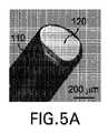
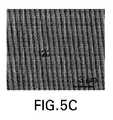
図5Aは、本開示の例示的実施形態による方法によって製作される例示的SEEプローブの先端の例示的に非常に拡大された写真を表す。SEEプローブの遠位先端の中心楕円領域は、緑である。それというのも、プローブの先端で形成される格子は、顕微鏡システムの照明光を回折して、この特定の視野角で顕微鏡カメラに優先的に緑光を向けるからである。緑の範囲の領域は、ミニチュア格子が良好に形成された領域を示した。格子の長軸に沿ったプローブ直径のほぼ86%および短軸に沿った78%は、緑の回折パターンを示した。SEEプローブの走査型電子顕微鏡(SEM)画像(例えば、図5B参照)は、6mmの作動距離で、2kVで、Zeiss Supra55 VP FESEMを用いて得られた。SEM画像取得の前に、画像のコントラストを改良するために、例示的SEEプローブは、シリコンウエハ上に置かれて、15〜45秒間、60mAでPt/Pdでスパッタリング被覆された。高倍率のSEM画像は、格子の規則的なラインパターンを明らかにする(例えば、図5C参照)。溝ピッチの標準偏差は、平均格子ピッチの約1.2%であることが測定された。 FIG. 5A represents an exemplary highly enlarged photograph of an exemplary SEE probe tip fabricated by a method according to an exemplary embodiment of the present disclosure. The central elliptical region of the distal tip of the SEE probe is green. This is because the grating formed at the tip of the probe diffracts the illumination light of the microscope system and directs green light preferentially to the microscope camera at this particular viewing angle. The area in the green range showed the area where the miniature grid was well formed. Approximately 86% of the probe diameter along the major axis of the grating and 78% along the minor axis showed a green diffraction pattern. Scanning electron microscope (SEM) images of the SEE probe (see, eg, FIG. 5B) were obtained using a Zeiss Supra55 VP FESEM at 2 kV with a working distance of 6 mm. Prior to SEM image acquisition, an exemplary SEE probe was placed on a silicon wafer and sputter coated with Pt / Pd at 60 mA for 15-45 seconds to improve image contrast. A high magnification SEM image reveals a regular line pattern of the grid (see, eg, FIG. 5C). The standard deviation of the groove pitch was measured to be about 1.2% of the average grid pitch.
図1に示される例示的ミニチュア格子120の回折性能は、試験された。例示的SEEプローブは、直線の虹として現れる、スペクトルでコード化された照射パターン600を生成した(図6参照)。+1番目の順序の回折効率、入力ビームの強度によって分割される+1番目の順序の強度は、約500のμmのビーム直径および約532ナノメートルの入力波長のための約75%であることが測定された。この回折効率は、マスター格子のそれ(例えば、約85%)よりも低い。格子直径は、プローブ直径よりも小さかった。したがって、光の一部は回折しなかった。そしてそれは、回折効率を減少させた。マスター格子と複製された格子との間の屈折率の差は、回折効率を減少させたかもしれない。 The diffraction performance of the exemplary miniature grating 120 shown in FIG. 1 was tested. The exemplary SEE probe generated a spectrally encoded illumination pattern 600 that appeared as a straight rainbow (see FIG. 6). + 1st order diffraction efficiency, + 1st order intensity divided by input beam intensity measured to be about 75% for beam diameter of about 500 μm and input wavelength of about 532 nanometers It was done. This diffraction efficiency is lower than that of the master grating (eg, about 85%). The grating diameter was smaller than the probe diameter. Therefore, part of the light did not diffract. And it reduced the diffraction efficiency. The refractive index difference between the master grating and the replicated grating may have reduced the diffraction efficiency.
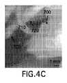
図7A〜図7Dは、本開示の例示的実施形態による方法によって製作される例示的SEEプローブで得られたマウス胚の一組の例示的SEE画像を示す。マウス胚は、ポリプロピレン50ml管の内側にいた。そして、SEE画像は、3.7%のホルムアルデヒド固定液のほぼ10mmの厚みの層を通して行われた。SEE画像(例えば、図7A〜図7C参照)は、頭部、目700、尾部710、および爪を有する足720を含む胚の解剖学的特徴の明白な可視化を容易にする。そしてそれは、同じ動物の写真に示されるそれらと類似している(例えば、図7D参照)。 7A-7D show a set of exemplary SEE images of a mouse embryo obtained with an exemplary SEE probe produced by a method according to an exemplary embodiment of the present disclosure. Mouse embryos were inside polypropylene 50 ml tubes. The SEE image was then passed through an approximately 10 mm thick layer of 3.7% formaldehyde fixative. SEE images (see, eg, FIGS. 7A-7C) facilitate the clear visualization of embryonic anatomical features including the head,
本開示の例示的実施形態による例示的製作方法の利点の1つは、例示的SEEプローブが低コストで作られることができるということである。例示的エラストマースタンプ(例えば、有効格子面積=13.5mm×12.5mm)は、ほぼ500μmの直径の格子を製作するためにスタンプの1mm×1mmの領域が必要であると仮定すると、ほぼ170個のミニチュア格子を製作することが必要でありえる。例えば、複数のエラストマースタンプは、マスターに損害を与えずに作られることができる。低コストは、安価でかつ使い捨て可能なSEEプローブの製作を可能にする。そしてそれは、この技術の臨床使用を容易にすることができる。 One advantage of an exemplary fabrication method according to exemplary embodiments of the present disclosure is that exemplary SEE probes can be made at low cost. An exemplary elastomeric stamp (eg, effective grid area = 13.5 mm × 12.5 mm) is approximately 170 assuming that a 1 mm × 1 mm area of the stamp is required to produce a grid of approximately 500 μm diameter. It may be necessary to make a miniature lattice of. For example, multiple elastomeric stamps can be made without damaging the master. The low cost allows the production of inexpensive and disposable SEE probes. And it can facilitate the clinical use of this technology.
本開示の例示的実施形態による例示的な製作方法が最終工程として画像光学系上にミニチュア格子を形成することができることも、有利である。例示的格子が製作プロセス中に適切に形成されないか、または使用中に損傷されるときに、SEEプローブの先端は、損傷を受けた格子を取り除くために非常に小さい量(〜20μm)によって容易に研磨されることができる。この例示的な修正動作の後、新たな格子は、次いで、同じ画像光学系上に製作されることができる。本開示の例示的実施形態による例示的な方法において、ミニチュア格子を取り扱って正確に整列配置するための手順は、必要でなくてもよい。そしてそれは、整列配置を必要とする方法に比べて例示的な製作プロセスをより簡単にする。 It is also advantageous that an exemplary fabrication method according to exemplary embodiments of the present disclosure can form a miniature grating on the imaging optics as a final step. When the exemplary grating is not properly formed during the fabrication process or is damaged during use, the tip of the SEE probe is easily reduced by a very small amount (˜20 μm) to remove the damaged grating. Can be polished. After this exemplary corrective action, a new grating can then be fabricated on the same imaging optics. In an exemplary method according to exemplary embodiments of the present disclosure, procedures for handling and accurately aligning miniature grids may not be necessary. And it makes the exemplary fabrication process easier than methods that require alignment.
本開示の例示的実施形態による典型的な製作方法の別の利点は、例示的SEEプローブのサイズがさらに減少することができるということである。例えば、約80μmの直径を有する超ミニチュアGRINレンズは、GRINtechによって最近開発された。本開示の例示的実施形態による例示的方法は80μmGRINレンズの先端で格子を作るために用いることができる。そしてそれは、100μmよりも小さい直径を有する超ミニチュアSEEプローブを考慮することを可能にすることができる。例えば、超ミニチュアSEEプローブの小さい直径は、従来の内視鏡画像形成デバイスによって目下アクセス可能でない内部組織の画像形成を容易にすることができる。 Another advantage of an exemplary fabrication method according to exemplary embodiments of the present disclosure is that the size of the exemplary SEE probe can be further reduced. For example, an ultra-miniature GRIN lens having a diameter of about 80 μm was recently developed by GRINtech. An exemplary method according to an exemplary embodiment of the present disclosure can be used to make a grating at the tip of an 80 μm GRIN lens. And it can make it possible to consider ultra-miniature SEE probes with a diameter smaller than 100 μm. For example, the small diameter of an ultra-miniature SEE probe can facilitate imaging of internal tissue that is not currently accessible by conventional endoscopic imaging devices.
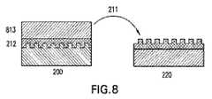
例示的なエラストマースタンプは、例えば、レプリカ成形プロセスの解像度を改善するために、2つの異なる材料で作られることができる。図8は、複合エラストマースタンプを製作するために用いることができる本開示の例示的実施形態による方法の例示的実施形態を示す。図8に示されるこの例示的実施形態において、高い硬化後剛性を有することができるエラストメリック・プレポリマー212は、格子マスター200上に配置されてよい。高い剛性を有するエラストマーの例は、h−PDMSでありえる。次いで、第1のエラストマー材料212よりも低い剛性を有することができる別のエラストメリック・プレポリマー813が、第1のエラストマー材料212の上部に注入されてよい。2つのエラストマー材料は、最終版のエラストマースタンプ220を完成するために、硬化することができて、剥ぎ取られることができる。 Exemplary elastomeric stamps can be made of two different materials, for example, to improve the resolution of the replica molding process. FIG. 8 illustrates an exemplary embodiment of a method according to an exemplary embodiment of the present disclosure that can be used to fabricate a composite elastomeric stamp. In this exemplary embodiment shown in FIG. 8, an
高アスペクト比を有する格子パターンを複製する際に、この例示的実施形態は、有利でありえる。エラストマースタンプ220が例えばSylgrad 184のような柔らかい材料で作られる場合、複製されたパターンは、格子パターンが高アスペクト比を有する場合に圧壊することができておよび/または垂下することができる。この例示的な複合スタンプ220は、(例えば、高解像度パターン転写を達成するに)より堅い層212および(例えば、外圧なしに表面との等角接触を容易にするために)より可撓性のサポート213の両方の利点を結合することができる。 This exemplary embodiment can be advantageous in replicating a grating pattern having a high aspect ratio. If the
図9は、本開示の例示的実施形態による例示的SEEプローブの一組の図を示し、この例示的実施形態において、遠位光学部品は、複数の光学コンポーネントを有する。例えば、ファイバ100からの光および/または他の電磁放射線は、集束レンズ110によって焦束されることができる。そして、サンプルからの光および/または他の電磁放射線は、追加的ファイバ(例えば、検出ファイバ111)によって集められることができる。集束レンズ110および検出ファイバ111は、格子の製作の前にアセンブルされることができる。次いで、ミニチュア格子120を完成するために、プレポリマー300は、集束レンズ110および検出ファイバ111の両方でありえて、硬化310されることができる。使用する光学コンポーネントの数および寸法に関係なく、本発明に記載されている方法は、設計の範囲のいかなる画像光学系のためにも用いられることができる。 FIG. 9 shows a set of views of an exemplary SEE probe according to an exemplary embodiment of the present disclosure, in which the distal optical component has a plurality of optical components. For example, light from the
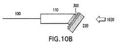
本開示のSEEプローブの別の例示的実施形態によれば、プレポリマーは、UV硬化可能なプレポリマーでありえる。UV硬化可能なプレポリマーは、図10の例示的図に示すようなものを含むさまざまな方法によって硬化することができる。例えば、図10Aに示すように、紫外光130は、ファイバ100に提供されることができておよび/または連結されることができる。この例示的実施形態において、重合するプレポリマー300の領域は、例えば、プローブ直径のサイズに制限されることができる。しかしながら、ファイバ100への硬化紫外光320の結合効率が低いときに、硬化時間は長くなりうる。図10Bにおいて、紫外光320は、エラストマースタンプ220の裏側から解放される。この例示的方法において、硬化は、急速に行われることができる。しかしながら、プレポリマーがプローブ直径よりも大きい領域まで広がる場合、ミニチュア格子の寸法は、プローブ直径よりも大きくなることができる。 According to another exemplary embodiment of the SEE probe of the present disclosure, the prepolymer can be a UV curable prepolymer. The UV curable prepolymer can be cured by a variety of methods including those shown in the exemplary diagram of FIG. For example, as shown in FIG. 10A,
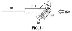
図11に示すように本開示によるSEEプローブの別の例示的実施形態において、硬化は、窒素リッチな環境下で行われることができる。例えば、窒素330は、プレポリマー300の周囲領域に提供されることができる。窒素は、酸素とプレポリマー300との接触を防止することができる。そしてそれは、ミニチュア格子の品質を改善することができる。 In another exemplary embodiment of a SEE probe according to the present disclosure as shown in FIG. 11, curing can be performed in a nitrogen rich environment. For example,
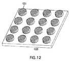
本開示による別の例示的実施態様において、エラストマースタンプ1220は、図12に示すように、複数の円形の柱で作られることができる。例えば、各柱1221は、上部に格子パターンを有することができる。そして、各柱の直径は、画像光学系の直径と同じである。この例示的スタンプは、画像光学系の直径の背後にエポキシが広がらないことを確実にすることができておよび/または容易にすることができて、そして、画像光学系の直径と同じ直径で広がる円形のエポキシを達成することを容易にすることができる。 In another exemplary embodiment according to the present disclosure, the
前述は、単に本発明の原理を例示するだけである。記載された実施形態に対するさまざまな修正および変更は、本明細書における教示からみて当業者にとって明らかである。実際、本発明の例示的実施形態による配置、システムおよび方法は、任意のOCTシステム、OFDlシステム、SD−OCTシステム、または他の画像形成システムとともに、そして、例えば、2004年9月8日出願の国際特許出願PCT/US2004/029148、2005年11月2日出願の米国特許出願第11/266,779号、および2004年7月9日出願の米国特許出願第10/501,276号に記載したそれらとともに、使用されることができる。そしてその開示内容は、全体として参照により本明細書に組み込まれる。明示的に示されないかまたは本明細書において記載されていないにもかかわらず、本発明の原理を具体化して、したがって、本発明の精神および範囲の範囲内である多数のシステム、配置および方法を当業者が考案するのが可能であることは、したがって、認められる。加えて、先行技術知識が上で本明細書において参照により明示的に組み込まれなかった程度まで、それは、全体として本明細書に明示的に組み込まれる。上で本明細書において参照されるすべての刊行物は、全体として参照により本明細書に組み込まれる。 The foregoing merely illustrates the principles of the invention. Various modifications and alterations to the described embodiments will be apparent to those skilled in the art in view of the teachings herein. Indeed, arrangements, systems and methods according to exemplary embodiments of the present invention may be used with any OCT system, OFDl system, SD-OCT system, or other imaging system, and for example, filed on Sep. 8, 2004. International Patent Application No. PCT / US2004 / 029148, U.S. Patent Application No. 11 / 266,779 filed on Nov. 2, 2005, and U.S. Patent Application No. 10 / 501,276 filed on Jul. 9, 2004. With them can be used. The disclosure of which is incorporated herein by reference in its entirety. There are numerous systems, arrangements and methods that embody the principles of the present invention and are therefore within the spirit and scope of the present invention, although not explicitly shown or described herein. It is therefore appreciated that one skilled in the art can devise. In addition, to the extent that prior art knowledge was not explicitly incorporated herein by reference, it is expressly incorporated herein in its entirety. All publications referenced herein above are hereby incorporated by reference in their entirety.
Claims (26)
Translated fromJapanese少なくとも1つのパターン化した表面を有するエラストマー材料を提供する手順、
プレポリマー接着剤配合物を用いて前記エラストマー材料を導波路配置の少なくとも一部と接続する手順、および、
前記エラストマー材料の構造または少なくとも1つの特徴を少なくともほぼ複製する前記回折構成を形成するように、前記プレポリマー接着剤配合物を重合させる手順、
を含む、方法。A method for providing a diffractive arrangement that diffracts in aspectrally encoded endoscopy optical arrangement comprising:
Providing an elastomeric material having at least one patterned surface;
Connecting the elastomeric material to at least a portion of the waveguide arrangement using a prepolymer adhesive formulation; and
Polymerizing the prepolymer adhesive formulation to form the diffractive configuration that at least substantially replicates the structure or at least one feature of the elastomeric material;
Including the method.
a.少なくとも1つのパターン化した表面を有するエラストマー材料を提供するために、
b.プレポリマー接着剤配合物を用いて前記エラストマー材料を導波路配置の少なくとも一部と接続するために、そして、
c.前記エラストマー材料の構造または少なくとも1つの特徴を少なくともほぼ複製する前記回折構成を形成するように、前記プレポリマー接着剤配合物を重合させるために、
プロセス構成をコントロールするように構成される処理コンピュータ装置、
を備える、システム。A system for providing a diffractive arrangement that diffracts in aspectrally encoded endoscopy optical arrangement, comprising:
a. To provide an elastomeric material having at least one patterned surface,
b. Connecting the elastomeric material with at least a portion of the waveguide arrangement using a prepolymer adhesive formulation; and
c. In order to polymerize the prepolymer adhesive formulation so as to form the diffractive configuration that at least substantially replicates the structure or at least one feature of the elastomeric material,
A processing computer device configured to control the process configuration;
A system comprising:
Applications Claiming Priority (5)
| Application Number | Priority Date | Filing Date | Title |
|---|---|---|---|
| US201261692117P | 2012-08-22 | 2012-08-22 | |
| US61/692,117 | 2012-08-22 | ||
| US201361779671P | 2013-03-13 | 2013-03-13 | |
| US61/779,671 | 2013-03-13 | ||
| PCT/US2013/055982WO2014031748A1 (en) | 2012-08-22 | 2013-08-21 | System, method, and computer-accessible medium for fabrication minature endoscope using soft lithography |
Publications (2)
| Publication Number | Publication Date |
|---|---|
| JP2015535941A JP2015535941A (en) | 2015-12-17 |
| JP6227652B2true JP6227652B2 (en) | 2017-11-08 |
Family
ID=50150363
Family Applications (1)
| Application Number | Title | Priority Date | Filing Date |
|---|---|---|---|
| JP2015528618AExpired - Fee RelatedJP6227652B2 (en) | 2012-08-22 | 2013-08-21 | System, method, and computer-accessible medium for fabricating a miniature endoscope using soft lithography |
Country Status (4)
| Country | Link |
|---|---|
| US (1) | US9415550B2 (en) |
| EP (1) | EP2888616A4 (en) |
| JP (1) | JP6227652B2 (en) |
| WO (1) | WO2014031748A1 (en) |
Families Citing this family (28)
| Publication number | Priority date | Publication date | Assignee | Title |
|---|---|---|---|---|
| US10095020B2 (en)* | 2014-01-31 | 2018-10-09 | Canon U.S.A., Inc. | Apparatus and methods for color endoscopy |
| US10261223B2 (en)* | 2014-01-31 | 2019-04-16 | Canon Usa, Inc. | System and method for fabrication of miniature endoscope using nanoimprint lithography |
| WO2015116951A2 (en) | 2014-01-31 | 2015-08-06 | Canon U.S.A., Inc. | Optical probe, light intensity detection, imaging method and system |
| WO2017024234A1 (en) | 2015-08-05 | 2017-02-09 | Canon U.S.A., Inc. | Endoscope probes and systems, and methods for use therewith |
| WO2017024145A1 (en) | 2015-08-05 | 2017-02-09 | Canon U.S.A., Inc. | Forward and angle view endoscope |
| US9869820B2 (en) | 2015-12-09 | 2018-01-16 | Canon U.S.A, Inc. | Optical probe, light intensity detection, imaging method and system |
| US9869854B2 (en) | 2015-12-16 | 2018-01-16 | Canon U.S.A, Inc. | Endoscopic system |
| WO2017117203A1 (en) | 2015-12-28 | 2017-07-06 | Canon U.S.A., Inc. | Optical probe, light intensity detection, imaging method and system |
| US10551245B2 (en) | 2016-02-12 | 2020-02-04 | Canon U.S.A., Inc. | Simple monolithic optical element for forward-viewing spectrally encoded endoscopy |
| US10321810B2 (en) | 2016-06-13 | 2019-06-18 | Canon U.S.A., Inc. | Spectrally encoded endoscopic probe having a fixed fiber |
| US10234694B2 (en) | 2016-07-15 | 2019-03-19 | Canon U.S.A., Inc. | Spectrally encoded probes |
| US10401610B2 (en) | 2016-07-15 | 2019-09-03 | Canon Usa, Inc. | Spectrally encoded probe with multiple diffraction orders |
| US10315371B2 (en)* | 2016-07-28 | 2019-06-11 | Microsoft Technology Licensing, Llc | Multiphase optical grating |
| JP2019534069A (en) | 2016-09-23 | 2019-11-28 | キヤノン ユーエスエイ, インコーポレイテッドCanon U.S.A., Inc | Spectral-coded endoscopy apparatus and method |
| US10898068B2 (en) | 2016-11-01 | 2021-01-26 | Canon U.S.A., Inc. | Multi-bandwidth spectrally encoded endoscope |
| JP2018094395A (en) | 2016-11-03 | 2018-06-21 | キヤノン ユーエスエイ, インコーポレイテッドCanon U.S.A., Inc | Diagnostic spectrally encoded endoscopy apparatuses and systems, and methods for use with the same |
| US10682044B2 (en) | 2017-01-12 | 2020-06-16 | Canon U.S.A., Inc. | Spectrally encoded forward view and spectrally encoded multi-view endoscope using back-reflected light between reflective surfaces |
| US10895692B2 (en) | 2017-06-01 | 2021-01-19 | Canon U.S.A., Inc. | Fiber optic rotary joints and methods of using and manufacturing same |
| US10825152B2 (en)* | 2017-09-14 | 2020-11-03 | Canon U.S.A., Inc. | Distortion measurement and correction for spectrally encoded endoscopy |
| US10357160B2 (en) | 2017-10-05 | 2019-07-23 | Canon U.S.A., Inc. | Image acquiring apparatus, systems, and methods |
| US11224336B2 (en) | 2017-11-17 | 2022-01-18 | Canon U.S.A., Inc. | Rotational extender and/or repeater for rotating fiber based optical imaging systems, and methods and storage mediums for use therewith |
| US10809538B2 (en) | 2017-11-27 | 2020-10-20 | Canon U.S.A., Inc. | Image acquisition apparatus, spectral apparatus, methods, and storage medium for use with same |
| US10506922B2 (en) | 2018-04-06 | 2019-12-17 | Canon U.S.A., Inc. | Spectrometer for color spectrally-encoded endoscopy |
| WO2020159984A1 (en) | 2019-01-30 | 2020-08-06 | Canon U.S.A., Inc. | Apparatuses, systems, methods and storage mediums for performance of co-registration |
| US12171410B2 (en) | 2019-02-05 | 2024-12-24 | Canon U.S.A., Inc. | Endoscope observation window cleaning |
| US11707186B2 (en) | 2019-06-14 | 2023-07-25 | Canon U.S.A., Inc. | Fluorescence or auto-fluorescence trigger or triggers |
| EP4024117B1 (en)* | 2019-08-27 | 2025-07-09 | FUJIFILM Corporation | Lighting optical system for endoscope |
| US12366441B2 (en) | 2020-08-06 | 2025-07-22 | Canon U.S.A., Inc. | Detector or photomultiplier tube (PMT) gain control over time |
Family Cites Families (541)
| Publication number | Priority date | Publication date | Assignee | Title |
|---|---|---|---|---|
| US2339754A (en) | 1941-03-04 | 1944-01-25 | Westinghouse Electric & Mfg Co | Supervisory apparatus |
| GB1257778A (en) | 1967-12-07 | 1971-12-22 | ||
| US3601480A (en) | 1968-07-10 | 1971-08-24 | Physics Int Co | Optical tunnel high-speed camera system |
| JPS4932484U (en) | 1972-06-19 | 1974-03-20 | ||
| FR2253410A5 (en) | 1973-12-03 | 1975-06-27 | Inst Nat Sante Rech Med | |
| US3941121A (en) | 1974-12-20 | 1976-03-02 | The University Of Cincinnati | Focusing fiber-optic needle endoscope |
| US3983507A (en) | 1975-01-06 | 1976-09-28 | Research Corporation | Tunable laser systems and method |
| US3973219A (en) | 1975-04-24 | 1976-08-03 | Cornell Research Foundation, Inc. | Very rapidly tuned cw dye laser |
| US4141362A (en) | 1977-05-23 | 1979-02-27 | Richard Wolf Gmbh | Laser endoscope |
| GB2030313A (en) | 1978-06-29 | 1980-04-02 | Wolf Gmbh Richard | Endoscopes |
| FR2448728A1 (en) | 1979-02-07 | 1980-09-05 | Thomson Csf | ROTATING JOINT DEVICE FOR OPTICAL CONDUCTOR CONNECTION AND SYSTEM COMPRISING SUCH A DEVICE |
| US4295738A (en) | 1979-08-30 | 1981-10-20 | United Technologies Corporation | Fiber optic strain sensor |
| US4300816A (en) | 1979-08-30 | 1981-11-17 | United Technologies Corporation | Wide band multicore optical fiber |
| US4428643A (en) | 1981-04-08 | 1984-01-31 | Xerox Corporation | Optical scanning system with wavelength shift correction |
| US5065331A (en) | 1981-05-18 | 1991-11-12 | Vachon Reginald I | Apparatus and method for determining the stress and strain in pipes, pressure vessels, structural members and other deformable bodies |
| GB2106736B (en) | 1981-09-03 | 1985-06-12 | Standard Telephones Cables Ltd | Optical transmission system |
| US4479499A (en) | 1982-01-29 | 1984-10-30 | Alfano Robert R | Method and apparatus for detecting the presence of caries in teeth using visible light |
| US5302025A (en) | 1982-08-06 | 1994-04-12 | Kleinerman Marcos Y | Optical systems for sensing temperature and other physical parameters |
| US4601036A (en) | 1982-09-30 | 1986-07-15 | Honeywell Inc. | Rapidly tunable laser |
| JPS5996983A (en) | 1982-11-26 | 1984-06-04 | Riso Kagaku Corp | Mimeographic plate printer |
| CH663466A5 (en) | 1983-09-12 | 1987-12-15 | Battelle Memorial Institute | METHOD AND DEVICE FOR DETERMINING THE POSITION OF AN OBJECT IN RELATION TO A REFERENCE. |
| US4639999A (en) | 1984-11-02 | 1987-02-03 | Xerox Corporation | High resolution, high efficiency I.R. LED printing array fabrication method |
| US4763977A (en) | 1985-01-09 | 1988-08-16 | Canadian Patents And Development Limited-Societe | Optical fiber coupler with tunable coupling ratio and method of making |
| EP0590268B1 (en) | 1985-03-22 | 1998-07-01 | Massachusetts Institute Of Technology | Fiber Optic Probe System for Spectrally Diagnosing Tissue |
| US5318024A (en) | 1985-03-22 | 1994-06-07 | Massachusetts Institute Of Technology | Laser endoscope for spectroscopic imaging |
| DE3610165A1 (en) | 1985-03-27 | 1986-10-02 | Olympus Optical Co., Ltd., Tokio/Tokyo | OPTICAL SCAN MICROSCOPE |
| US4607622A (en) | 1985-04-11 | 1986-08-26 | Charles D. Fritch | Fiber optic ocular endoscope |
| US4631498A (en) | 1985-04-26 | 1986-12-23 | Hewlett-Packard Company | CW Laser wavemeter/frequency locking technique |
| JPS62188001U (en) | 1986-05-20 | 1987-11-30 | ||
| US5040889A (en) | 1986-05-30 | 1991-08-20 | Pacific Scientific Company | Spectrometer with combined visible and ultraviolet sample illumination |
| CA1290019C (en) | 1986-06-20 | 1991-10-01 | Hideo Kuwahara | Dual balanced optical signal receiver |
| US4770492A (en) | 1986-10-28 | 1988-09-13 | Spectran Corporation | Pressure or strain sensitive optical fiber |
| CA1339426C (en) | 1987-09-01 | 1997-09-02 | Michael R. Layton | Hydrophone demodulator circuit and method |
| US5202931A (en) | 1987-10-06 | 1993-04-13 | Cell Analysis Systems, Inc. | Methods and apparatus for the quantitation of nuclear protein |
| US4892406A (en) | 1988-01-11 | 1990-01-09 | United Technologies Corporation | Method of and arrangement for measuring vibrations |
| FR2626367B1 (en) | 1988-01-25 | 1990-05-11 | Thomson Csf | MULTI-POINT FIBER OPTIC TEMPERATURE SENSOR |
| FR2626383B1 (en) | 1988-01-27 | 1991-10-25 | Commissariat Energie Atomique | EXTENDED FIELD SCAN AND DEPTH CONFOCAL OPTICAL MICROSCOPY AND DEVICES FOR CARRYING OUT THE METHOD |
| US4925302A (en) | 1988-04-13 | 1990-05-15 | Hewlett-Packard Company | Frequency locking device |
| DE02012428T1 (en) | 1988-07-13 | 2005-12-15 | Optiscan Pty. Ltd., Toorak | Confocal scanning microscope |
| GB8817672D0 (en) | 1988-07-25 | 1988-09-01 | Sira Ltd | Optical apparatus |
| US4868834A (en) | 1988-09-14 | 1989-09-19 | The United States Of America As Represented By The Secretary Of The Army | System for rapidly tuning a low pressure pulsed laser |
| DE3833602A1 (en) | 1988-10-03 | 1990-02-15 | Krupp Gmbh | SPECTROMETER FOR SIMULTANEOUS INTENSITY MEASUREMENT IN DIFFERENT SPECTRAL AREAS |
| US4940328A (en) | 1988-11-04 | 1990-07-10 | Georgia Tech Research Corporation | Optical sensing apparatus and method |
| US4966589A (en) | 1988-11-14 | 1990-10-30 | Hemedix International, Inc. | Intravenous catheter placement device |
| DE68925586T2 (en) | 1988-12-21 | 1996-10-24 | Massachusetts Inst Technology | METHOD FOR LASER-INDUCED FLUORESCENCE OF TISSUE |
| US5046501A (en) | 1989-01-18 | 1991-09-10 | Wayne State University | Atherosclerotic identification |
| US5317389A (en) | 1989-06-12 | 1994-05-31 | California Institute Of Technology | Method and apparatus for white-light dispersed-fringe interferometric measurement of corneal topography |
| US4965599A (en) | 1989-11-13 | 1990-10-23 | Eastman Kodak Company | Scanning apparatus for halftone image screen writing |
| US4984888A (en) | 1989-12-13 | 1991-01-15 | Imo Industries, Inc. | Two-dimensional spectrometer |
| US5251009A (en) | 1990-01-22 | 1993-10-05 | Ciba-Geigy Corporation | Interferometric measuring arrangement for refractive index measurements in capillary tubes |
| DD293205B5 (en) | 1990-03-05 | 1995-06-29 | Zeiss Carl Jena Gmbh | Optical fiber guide for a medical observation device |
| US5039193A (en) | 1990-04-03 | 1991-08-13 | Focal Technologies Incorporated | Fibre optic single mode rotary joint |
| US5262644A (en) | 1990-06-29 | 1993-11-16 | Southwest Research Institute | Remote spectroscopy for raman and brillouin scattering |
| US5197470A (en) | 1990-07-16 | 1993-03-30 | Eastman Kodak Company | Near infrared diagnostic method and instrument |
| GB9015793D0 (en) | 1990-07-18 | 1990-09-05 | Medical Res Council | Confocal scanning optical microscope |
| US5845639A (en) | 1990-08-10 | 1998-12-08 | Board Of Regents Of The University Of Washington | Optical imaging methods |
| US5127730A (en) | 1990-08-10 | 1992-07-07 | Regents Of The University Of Minnesota | Multi-color laser scanning confocal imaging system |
| JP2543516Y2 (en) | 1990-09-25 | 1997-08-06 | 因幡電機産業株式会社 | Connector |
| US5305759A (en) | 1990-09-26 | 1994-04-26 | Olympus Optical Co., Ltd. | Examined body interior information observing apparatus by using photo-pulses controlling gains for depths |
| US5202745A (en) | 1990-11-07 | 1993-04-13 | Hewlett-Packard Company | Polarization independent optical coherence-domain reflectometry |
| JP3035336B2 (en) | 1990-11-27 | 2000-04-24 | 興和株式会社 | Blood flow measurement device |
| US5228001A (en) | 1991-01-23 | 1993-07-13 | Syracuse University | Optical random access memory |
| US5784162A (en) | 1993-08-18 | 1998-07-21 | Applied Spectral Imaging Ltd. | Spectral bio-imaging methods for biological research, medical diagnostics and therapy |
| US6198532B1 (en) | 1991-02-22 | 2001-03-06 | Applied Spectral Imaging Ltd. | Spectral bio-imaging of the eye |
| US5293872A (en) | 1991-04-03 | 1994-03-15 | Alfano Robert R | Method for distinguishing between calcified atherosclerotic tissue and fibrous atherosclerotic tissue or normal cardiovascular tissue using Raman spectroscopy |
| US5956355A (en) | 1991-04-29 | 1999-09-21 | Massachusetts Institute Of Technology | Method and apparatus for performing optical measurements using a rapidly frequency-tuned laser |
| US6134003A (en) | 1991-04-29 | 2000-10-17 | Massachusetts Institute Of Technology | Method and apparatus for performing optical measurements using a fiber optic imaging guidewire, catheter or endoscope |
| US6111645A (en) | 1991-04-29 | 2000-08-29 | Massachusetts Institute Of Technology | Grating based phase control optical delay line |
| US6485413B1 (en) | 1991-04-29 | 2002-11-26 | The General Hospital Corporation | Methods and apparatus for forward-directed optical scanning instruments |
| US5465147A (en) | 1991-04-29 | 1995-11-07 | Massachusetts Institute Of Technology | Method and apparatus for acquiring images using a ccd detector array and no transverse scanner |
| JP3479069B2 (en) | 1991-04-29 | 2003-12-15 | マサチューセッツ・インステチュート・オブ・テクノロジー | Method and apparatus for optical imaging and measurement |
| US6564087B1 (en) | 1991-04-29 | 2003-05-13 | Massachusetts Institute Of Technology | Fiber optic needle probes for optical coherence tomography imaging |
| US5748598A (en) | 1995-12-22 | 1998-05-05 | Massachusetts Institute Of Technology | Apparatus and methods for reading multilayer storage media using short coherence length sources |
| US6501551B1 (en) | 1991-04-29 | 2002-12-31 | Massachusetts Institute Of Technology | Fiber optic imaging endoscope interferometer with at least one faraday rotator |
| US5441053A (en) | 1991-05-03 | 1995-08-15 | University Of Kentucky Research Foundation | Apparatus and method for multiple wavelength of tissue |
| US5281811A (en) | 1991-06-17 | 1994-01-25 | Litton Systems, Inc. | Digital wavelength division multiplex optical transducer having an improved decoder |
| WO1993003672A1 (en) | 1991-08-20 | 1993-03-04 | Redd Douglas C B | Optical histochemical analysis, in vivo detection and real-time guidance for ablation of abnormal tissues using a raman spectroscopic detection system |
| DE4128744C1 (en) | 1991-08-29 | 1993-04-22 | Siemens Ag, 8000 Muenchen, De | |
| US5177488A (en) | 1991-10-08 | 1993-01-05 | Hughes Aircraft Company | Programmable fiber optic delay line, and radar target simulation system incorporating the same |
| ATE150573T1 (en) | 1991-12-30 | 1997-04-15 | Philips Electronics Nv | OPTICAL DEVICE AND DEVICE PROVIDED WITH SUCH AN OPTICAL DEVICE FOR SCANNING AN INFORMATION PLANE |
| US5353790A (en) | 1992-01-17 | 1994-10-11 | Board Of Regents, The University Of Texas System | Method and apparatus for optical measurement of bilirubin in tissue |
| US5217456A (en) | 1992-02-24 | 1993-06-08 | Pdt Cardiovascular, Inc. | Device and method for intra-vascular optical radial imaging |
| US5283795A (en) | 1992-04-21 | 1994-02-01 | Hughes Aircraft Company | Diffraction grating driven linear frequency chirped laser |
| US5248876A (en) | 1992-04-21 | 1993-09-28 | International Business Machines Corporation | Tandem linear scanning confocal imaging system with focal volumes at different heights |
| US5486701A (en) | 1992-06-16 | 1996-01-23 | Prometrix Corporation | Method and apparatus for measuring reflectance in two wavelength bands to enable determination of thin film thickness |
| US5411025A (en) | 1992-06-30 | 1995-05-02 | Cordis Webster, Inc. | Cardiovascular catheter with laterally stable basket-shaped electrode array |
| US5716324A (en) | 1992-08-25 | 1998-02-10 | Fuji Photo Film Co., Ltd. | Endoscope with surface and deep portion imaging systems |
| EP0587514A1 (en) | 1992-09-11 | 1994-03-16 | Welch Allyn, Inc. | Processor module for video inspection probe |
| US5772597A (en) | 1992-09-14 | 1998-06-30 | Sextant Medical Corporation | Surgical tool end effector |
| US5698397A (en) | 1995-06-07 | 1997-12-16 | Sri International | Up-converting reporters for biological and other assays using laser excitation techniques |
| DE69327147T2 (en) | 1992-09-21 | 2000-06-15 | Institut National De La Sante Et De La Recherche Medicale I.N.S.E.R.M., Paris | Probe and method for accurately determining the speed or flow of a liquid |
| US5383467A (en) | 1992-11-18 | 1995-01-24 | Spectrascience, Inc. | Guidewire catheter and apparatus for diagnostic imaging |
| ATE151615T1 (en) | 1992-11-18 | 1997-05-15 | Spectrascience Inc | DIAGNOSTIC IMAGE DEVICE |
| US5785663A (en) | 1992-12-21 | 1998-07-28 | Artann Corporation | Method and device for mechanical imaging of prostate |
| US5400771A (en) | 1993-01-21 | 1995-03-28 | Pirak; Leon | Endotracheal intubation assembly and related method |
| JPH06222242A (en) | 1993-01-27 | 1994-08-12 | Shin Etsu Chem Co Ltd | Optical fiber coupler and manufacturing method thereof |
| US5987346A (en) | 1993-02-26 | 1999-11-16 | Benaron; David A. | Device and method for classification of tissue |
| US5414509A (en) | 1993-03-08 | 1995-05-09 | Associated Universities, Inc. | Optical pressure/density measuring means |
| DE4309056B4 (en) | 1993-03-20 | 2006-05-24 | Häusler, Gerd, Prof. Dr. | Method and device for determining the distance and scattering intensity of scattering points |
| DE4310209C2 (en) | 1993-03-29 | 1996-05-30 | Bruker Medizintech | Optical stationary imaging in strongly scattering media |
| SE501932C2 (en) | 1993-04-30 | 1995-06-26 | Ericsson Telefon Ab L M | Apparatus and method for dispersion compensation in a fiber optic transmission system |
| US5424827A (en) | 1993-04-30 | 1995-06-13 | Litton Systems, Inc. | Optical system and method for eliminating overlap of diffraction spectra |
| DE4314189C1 (en) | 1993-04-30 | 1994-11-03 | Bodenseewerk Geraetetech | Device for the examination of optical fibres made of glass by means of heterodyne Brillouin spectroscopy |
| US5454807A (en) | 1993-05-14 | 1995-10-03 | Boston Scientific Corporation | Medical treatment of deeply seated tissue using optical radiation |
| EP0627643B1 (en) | 1993-06-03 | 1999-05-06 | Hamamatsu Photonics K.K. | Laser scanning optical system using axicon |
| US5840031A (en) | 1993-07-01 | 1998-11-24 | Boston Scientific Corporation | Catheters for imaging, sensing electrical potentials and ablating tissue |
| US5995645A (en) | 1993-08-18 | 1999-11-30 | Applied Spectral Imaging Ltd. | Method of cancer cell detection |
| US5803082A (en) | 1993-11-09 | 1998-09-08 | Staplevision Inc. | Omnispectramammography |
| US5983125A (en) | 1993-12-13 | 1999-11-09 | The Research Foundation Of City College Of New York | Method and apparatus for in vivo examination of subcutaneous tissues inside an organ of a body using optical spectroscopy |
| US5450203A (en) | 1993-12-22 | 1995-09-12 | Electroglas, Inc. | Method and apparatus for determining an objects position, topography and for imaging |
| US5411016A (en) | 1994-02-22 | 1995-05-02 | Scimed Life Systems, Inc. | Intravascular balloon catheter for use in combination with an angioscope |
| US5590660A (en) | 1994-03-28 | 1997-01-07 | Xillix Technologies Corp. | Apparatus and method for imaging diseased tissue using integrated autofluorescence |
| DE4411017C2 (en) | 1994-03-30 | 1995-06-08 | Alexander Dr Knuettel | Optical stationary spectroscopic imaging in strongly scattering objects through special light focusing and signal detection of light of different wavelengths |
| TW275570B (en) | 1994-05-05 | 1996-05-11 | Boehringer Mannheim Gmbh | |
| WO1996002184A1 (en) | 1994-07-14 | 1996-02-01 | Washington Research Foundation | Method and apparatus for detecting barrett's metaplasia of the esophagus |
| US5459325A (en) | 1994-07-19 | 1995-10-17 | Molecular Dynamics, Inc. | High-speed fluorescence scanner |
| US6159445A (en) | 1994-07-20 | 2000-12-12 | Nycomed Imaging As | Light imaging contrast agents |
| WO1996004839A1 (en) | 1994-08-08 | 1996-02-22 | Computed Anatomy, Incorporated | Processing of keratoscopic images using local spatial phase |
| EP1231496B1 (en) | 1994-08-18 | 2004-12-29 | Carl Zeiss AG | Optical coherence tomography assisted surgical apparatus |
| US5491524A (en) | 1994-10-05 | 1996-02-13 | Carl Zeiss, Inc. | Optical coherence tomography corneal mapping apparatus |
| US5740808A (en) | 1996-10-28 | 1998-04-21 | Ep Technologies, Inc | Systems and methods for guilding diagnostic or therapeutic devices in interior tissue regions |
| US5817144A (en) | 1994-10-25 | 1998-10-06 | Latis, Inc. | Method for contemporaneous application OF laser energy and localized pharmacologic therapy |
| US6033721A (en) | 1994-10-26 | 2000-03-07 | Revise, Inc. | Image-based three-axis positioner for laser direct write microchemical reaction |
| JPH08136345A (en) | 1994-11-10 | 1996-05-31 | Anritsu Corp | Double monochromator |
| JPH08160129A (en) | 1994-12-05 | 1996-06-21 | Uniden Corp | Speed detector |
| US5600486A (en) | 1995-01-30 | 1997-02-04 | Lockheed Missiles And Space Company, Inc. | Color separation microlens |
| RU2100787C1 (en) | 1995-03-01 | 1997-12-27 | Геликонов Валентин Михайлович | Fibre-optical interferometer and fiber-optical piezoelectric transducer |
| WO1996028212A1 (en) | 1995-03-09 | 1996-09-19 | Innotech Usa, Inc. | Laser surgical device and method of its use |
| US5868731A (en) | 1996-03-04 | 1999-02-09 | Innotech Usa, Inc. | Laser surgical device and method of its use |
| US5526338A (en) | 1995-03-10 | 1996-06-11 | Yeda Research & Development Co. Ltd. | Method and apparatus for storage and retrieval with multilayer optical disks |
| US5697373A (en) | 1995-03-14 | 1997-12-16 | Board Of Regents, The University Of Texas System | Optical method and apparatus for the diagnosis of cervical precancers using raman and fluorescence spectroscopies |
| US5735276A (en) | 1995-03-21 | 1998-04-07 | Lemelson; Jerome | Method and apparatus for scanning and evaluating matter |
| US5565983A (en) | 1995-05-26 | 1996-10-15 | The Perkin-Elmer Corporation | Optical spectrometer for detecting spectra in separate ranges |
| US5785651A (en) | 1995-06-07 | 1998-07-28 | Keravision, Inc. | Distance measuring confocal microscope |
| US5621830A (en) | 1995-06-07 | 1997-04-15 | Smith & Nephew Dyonics Inc. | Rotatable fiber optic joint |
| WO1997001167A1 (en) | 1995-06-21 | 1997-01-09 | Massachusetts Institute Of Technology | Apparatus and method for accessing data on multilayered optical media |
| ATA107495A (en) | 1995-06-23 | 1996-06-15 | Fercher Adolf Friedrich Dr | COHERENCE BIOMETRY AND TOMOGRAPHY WITH DYNAMIC COHERENT FOCUS |
| JP3654309B2 (en) | 1995-06-28 | 2005-06-02 | 株式会社日立メディコ | Acicular ultrasonic probe |
| US5829439A (en) | 1995-06-28 | 1998-11-03 | Hitachi Medical Corporation | Needle-like ultrasonic probe for ultrasonic diagnosis apparatus, method of producing same, and ultrasonic diagnosis apparatus using same |
| US6104945A (en) | 1995-08-01 | 2000-08-15 | Medispectra, Inc. | Spectral volume microprobe arrays |
| AU1130797A (en) | 1995-08-24 | 1997-03-19 | Purdue Research Foundation | Fluorescence lifetime-based imaging and spectroscopy in tissues and other random media |
| US6615071B1 (en) | 1995-09-20 | 2003-09-02 | Board Of Regents, The University Of Texas System | Method and apparatus for detecting vulnerable atherosclerotic plaque |
| US5742419A (en) | 1995-11-07 | 1998-04-21 | The Board Of Trustees Of The Leland Stanford Junior Universtiy | Miniature scanning confocal microscope |
| DE19542955C2 (en) | 1995-11-17 | 1999-02-18 | Schwind Gmbh & Co Kg Herbert | endoscope |
| US5719399A (en) | 1995-12-18 | 1998-02-17 | The Research Foundation Of City College Of New York | Imaging and characterization of tissue based upon the preservation of polarized light transmitted therethrough |
| JP3699761B2 (en) | 1995-12-26 | 2005-09-28 | オリンパス株式会社 | Epifluorescence microscope |
| US5840023A (en) | 1996-01-31 | 1998-11-24 | Oraevsky; Alexander A. | Optoacoustic imaging for medical diagnosis |
| US5862273A (en) | 1996-02-23 | 1999-01-19 | Kaiser Optical Systems, Inc. | Fiber optic probe with integral optical filtering |
| US5843000A (en) | 1996-05-07 | 1998-12-01 | The General Hospital Corporation | Optical biopsy forceps and method of diagnosing tissue |
| ATA84696A (en) | 1996-05-14 | 1998-03-15 | Adolf Friedrich Dr Fercher | METHOD AND ARRANGEMENTS FOR INCREASING CONTRAST IN OPTICAL COHERENCE TOMOGRAPHY |
| US5795295A (en) | 1996-06-25 | 1998-08-18 | Carl Zeiss, Inc. | OCT-assisted surgical microscope with multi-coordinate manipulator |
| US5842995A (en) | 1996-06-28 | 1998-12-01 | Board Of Regents, The Univerisity Of Texas System | Spectroscopic probe for in vivo measurement of raman signals |
| US6296608B1 (en) | 1996-07-08 | 2001-10-02 | Boston Scientific Corporation | Diagnosing and performing interventional procedures on tissue in vivo |
| US5840075A (en) | 1996-08-23 | 1998-11-24 | Eclipse Surgical Technologies, Inc. | Dual laser device for transmyocardial revascularization procedures |
| US6544193B2 (en) | 1996-09-04 | 2003-04-08 | Marcio Marc Abreu | Noninvasive measurement of chemical substances |
| US5801831A (en) | 1996-09-20 | 1998-09-01 | Institute For Space And Terrestrial Science | Fabry-Perot spectrometer for detecting a spatially varying spectral signature of an extended source |
| RU2108122C1 (en) | 1996-09-24 | 1998-04-10 | Владимир Павлович Жаров | Method and device for physiotherapeutic irradiation with light |
| US6249349B1 (en) | 1996-09-27 | 2001-06-19 | Vincent Lauer | Microscope generating a three-dimensional representation of an object |
| DE19640495C2 (en) | 1996-10-01 | 1999-12-16 | Leica Microsystems | Device for confocal surface measurement |
| US5843052A (en) | 1996-10-04 | 1998-12-01 | Benja-Athon; Anuthep | Irrigation kit for application of fluids and chemicals for cleansing and sterilizing wounds |
| US5904651A (en) | 1996-10-28 | 1999-05-18 | Ep Technologies, Inc. | Systems and methods for visualizing tissue during diagnostic or therapeutic procedures |
| US5752518A (en) | 1996-10-28 | 1998-05-19 | Ep Technologies, Inc. | Systems and methods for visualizing interior regions of the body |
| US6044288A (en) | 1996-11-08 | 2000-03-28 | Imaging Diagnostics Systems, Inc. | Apparatus and method for determining the perimeter of the surface of an object being scanned |
| US5872879A (en) | 1996-11-25 | 1999-02-16 | Boston Scientific Corporation | Rotatable connecting optical fibers |
| US6437867B2 (en) | 1996-12-04 | 2002-08-20 | The Research Foundation Of The City University Of New York | Performing selected optical measurements with optical coherence domain reflectometry |
| US6249630B1 (en) | 1996-12-13 | 2001-06-19 | Imra America, Inc. | Apparatus and method for delivery of dispersion-compensated ultrashort optical pulses with high peak power |
| US5906759A (en) | 1996-12-26 | 1999-05-25 | Medinol Ltd. | Stent forming apparatus with stent deforming blades |
| US5871449A (en) | 1996-12-27 | 1999-02-16 | Brown; David Lloyd | Device and method for locating inflamed plaque in an artery |
| WO1998029768A1 (en) | 1996-12-31 | 1998-07-09 | Corning Incorporated | Optical couplers with multilayer fibers |
| US5991697A (en) | 1996-12-31 | 1999-11-23 | The Regents Of The University Of California | Method and apparatus for optical Doppler tomographic imaging of fluid flow velocity in highly scattering media |
| US5760901A (en) | 1997-01-28 | 1998-06-02 | Zetetic Institute | Method and apparatus for confocal interference microscopy with background amplitude reduction and compensation |
| JP3213250B2 (en) | 1997-01-29 | 2001-10-02 | 株式会社生体光情報研究所 | Optical measurement device |
| US5801826A (en) | 1997-02-18 | 1998-09-01 | Williams Family Trust B | Spectrometric device and method for recognizing atomic and molecular signatures |
| US5836877A (en) | 1997-02-24 | 1998-11-17 | Lucid Inc | System for facilitating pathological examination of a lesion in tissue |
| US6010449A (en) | 1997-02-28 | 2000-01-04 | Lumend, Inc. | Intravascular catheter system for treating a vascular occlusion |
| US5968064A (en) | 1997-02-28 | 1999-10-19 | Lumend, Inc. | Catheter system for treating a vascular occlusion |
| US6120516A (en) | 1997-02-28 | 2000-09-19 | Lumend, Inc. | Method for treating vascular occlusion |
| JP2001515382A (en) | 1997-03-06 | 2001-09-18 | マサチューセッツ インスティチュート オブ テクノロジー | Equipment for optical scanning of living tissue |
| US6201989B1 (en) | 1997-03-13 | 2001-03-13 | Biomax Technologies Inc. | Methods and apparatus for detecting the rejection of transplanted tissue |
| US6078047A (en) | 1997-03-14 | 2000-06-20 | Lucent Technologies Inc. | Method and apparatus for terahertz tomographic imaging |
| US5994690A (en) | 1997-03-17 | 1999-11-30 | Kulkarni; Manish D. | Image enhancement in optical coherence tomography using deconvolution |
| JPH10267830A (en) | 1997-03-26 | 1998-10-09 | Kowa Co | Optical measuring device |
| JPH10267631A (en) | 1997-03-26 | 1998-10-09 | Kowa Co | Optical measuring device |
| GB9707414D0 (en) | 1997-04-11 | 1997-05-28 | Imperial College | Anatomical probe |
| DE69820867T2 (en) | 1997-04-29 | 2004-11-18 | Amersham Health As | LIGHT IMAGING CONTRAST AGENTS |
| US6117128A (en) | 1997-04-30 | 2000-09-12 | Kenton W. Gregory | Energy delivery catheter and method for the use thereof |
| US5887009A (en) | 1997-05-22 | 1999-03-23 | Optical Biopsy Technologies, Inc. | Confocal optical scanning system employing a fiber laser |
| JP4138027B2 (en) | 1997-06-02 | 2008-08-20 | イザット,ジョーゼフ,エイ. | Imaging Doppler flow using optical coherence tomography |
| US6002480A (en) | 1997-06-02 | 1999-12-14 | Izatt; Joseph A. | Depth-resolved spectroscopic optical coherence tomography |
| US6208415B1 (en) | 1997-06-12 | 2001-03-27 | The Regents Of The University Of California | Birefringence imaging in biological tissue using polarization sensitive optical coherent tomography |
| EP0989822A4 (en) | 1997-06-23 | 2004-07-28 | Focus Surgery Inc | Methods and devices for providing acoustic hemostasis |
| US5920390A (en) | 1997-06-26 | 1999-07-06 | University Of North Carolina | Fiberoptic interferometer and associated method for analyzing tissue |
| US6048349A (en) | 1997-07-09 | 2000-04-11 | Intraluminal Therapeutics, Inc. | Systems and methods for guiding a medical instrument through a body |
| US6058352A (en) | 1997-07-25 | 2000-05-02 | Physical Optics Corporation | Accurate tissue injury assessment using hybrid neural network analysis |
| US5921926A (en) | 1997-07-28 | 1999-07-13 | University Of Central Florida | Three dimensional optical imaging colposcopy |
| US5892583A (en) | 1997-08-21 | 1999-04-06 | Li; Ming-Chiang | High speed inspection of a sample using superbroad radiation coherent interferometer |
| US6014214A (en) | 1997-08-21 | 2000-01-11 | Li; Ming-Chiang | High speed inspection of a sample using coherence processing of scattered superbroad radiation |
| US6069698A (en) | 1997-08-28 | 2000-05-30 | Olympus Optical Co., Ltd. | Optical imaging apparatus which radiates a low coherence light beam onto a test object, receives optical information from light scattered by the object, and constructs therefrom a cross-sectional image of the object |
| US5920373A (en) | 1997-09-24 | 1999-07-06 | Heidelberg Engineering Optische Messysteme Gmbh | Method and apparatus for determining optical characteristics of a cornea |
| US5951482A (en) | 1997-10-03 | 1999-09-14 | Intraluminal Therapeutics, Inc. | Assemblies and methods for advancing a guide wire through body tissue |
| US6193676B1 (en) | 1997-10-03 | 2001-02-27 | Intraluminal Therapeutics, Inc. | Guide wire assembly |
| US6091984A (en) | 1997-10-10 | 2000-07-18 | Massachusetts Institute Of Technology | Measuring tissue morphology |
| US6052186A (en) | 1997-11-05 | 2000-04-18 | Excel Precision, Inc. | Dual laser system for extended heterodyne interferometry |
| US6134010A (en) | 1997-11-07 | 2000-10-17 | Lucid, Inc. | Imaging system using polarization effects to enhance image quality |
| US6037579A (en) | 1997-11-13 | 2000-03-14 | Biophotonics Information Laboratories, Ltd. | Optical interferometer employing multiple detectors to detect spatially distorted wavefront in imaging of scattering media |
| US6107048A (en) | 1997-11-20 | 2000-08-22 | Medical College Of Georgia Research Institute, Inc. | Method of detecting and grading dysplasia in epithelial tissue |
| GB2349730B (en) | 1998-01-28 | 2003-04-09 | Ht Medical Systems Inc | Interface device and method for interfacing instruments to medical procedure simulation system |
| US6165170A (en) | 1998-01-29 | 2000-12-26 | International Business Machines Corporation | Laser dermablator and dermablation |
| JP4709969B2 (en) | 1998-02-26 | 2011-06-29 | ザ ジェネラル ホスピタル コーポレイション | Confocal microscopy using multispectral coding |
| US6134033A (en) | 1998-02-26 | 2000-10-17 | Tyco Submarine Systems Ltd. | Method and apparatus for improving spectral efficiency in wavelength division multiplexed transmission systems |
| US6048742A (en) | 1998-02-26 | 2000-04-11 | The United States Of America As Represented By The Secretary Of The Air Force | Process for measuring the thickness and composition of thin semiconductor films deposited on semiconductor wafers |
| US6831781B2 (en) | 1998-02-26 | 2004-12-14 | The General Hospital Corporation | Confocal microscopy with multi-spectral encoding and system and apparatus for spectroscopically encoded confocal microscopy |
| RU2148378C1 (en) | 1998-03-06 | 2000-05-10 | Геликонов Валентин Михайлович | Device for performing optic coherent tomography, optic fiber scanning device and method for diagnosing biological tissue in vivo |
| US6174291B1 (en) | 1998-03-09 | 2001-01-16 | Spectrascience, Inc. | Optical biopsy system and methods for tissue diagnosis |
| US6066102A (en) | 1998-03-09 | 2000-05-23 | Spectrascience, Inc. | Optical biopsy forceps system and method of diagnosing tissue |
| US6151522A (en) | 1998-03-16 | 2000-11-21 | The Research Foundation Of Cuny | Method and system for examining biological materials using low power CW excitation raman spectroscopy |
| US6175669B1 (en) | 1998-03-30 | 2001-01-16 | The Regents Of The Universtiy Of California | Optical coherence domain reflectometry guidewire |
| US6384915B1 (en) | 1998-03-30 | 2002-05-07 | The Regents Of The University Of California | Catheter guided by optical coherence domain reflectometry |
| DE19814057B4 (en) | 1998-03-30 | 2009-01-02 | Carl Zeiss Meditec Ag | Arrangement for optical coherence tomography and coherence topography |
| US5975699A (en) | 1998-04-29 | 1999-11-02 | Carl Zeiss, Inc. | Method and apparatus for simultaneously measuring the length and refractive error of an eye |
| US6996549B2 (en) | 1998-05-01 | 2006-02-07 | Health Discovery Corporation | Computer-aided image analysis |
| WO1999057507A1 (en) | 1998-05-01 | 1999-11-11 | Board Of Regents, The University Of Texas System | Method and apparatus for subsurface imaging |
| US6053613A (en) | 1998-05-15 | 2000-04-25 | Carl Zeiss, Inc. | Optical coherence tomography with new interferometer |
| FR2778838A1 (en) | 1998-05-19 | 1999-11-26 | Koninkl Philips Electronics Nv | METHOD FOR DETECTING VARIATIONS IN ELASTICITY AND ECHOGRAPHIC APPARATUS FOR CARRYING OUT THIS METHOD |
| JPH11352409A (en) | 1998-06-05 | 1999-12-24 | Olympus Optical Co Ltd | Fluorescence detector |
| US6549801B1 (en) | 1998-06-11 | 2003-04-15 | The Regents Of The University Of California | Phase-resolved optical coherence tomography and optical doppler tomography for imaging fluid flow in tissue with fast scanning speed and high velocity sensitivity |
| AU5101699A (en) | 1998-07-15 | 2000-02-07 | Corazon Technologies, Inc. | Methods and devices for reducing the mineral content of vascular calcified lesions |
| US6166373A (en) | 1998-07-21 | 2000-12-26 | The Institute For Technology Development | Focal plane scanner with reciprocating spatial window |
| JP2000046729A (en) | 1998-07-31 | 2000-02-18 | Takahisa Mitsui | Apparatus and method for high-speed measurement of optical topographic image by using wavelength dispersion |
| US20040140130A1 (en) | 1998-08-31 | 2004-07-22 | Halliburton Energy Services, Inc., A Delaware Corporation | Roller-cone bits, systems, drilling methods, and design methods with optimization of tooth orientation |
| US6741884B1 (en) | 1998-09-03 | 2004-05-25 | Hypermed, Inc. | Infrared endoscopic balloon probes |
| US8024027B2 (en) | 1998-09-03 | 2011-09-20 | Hyperspectral Imaging, Inc. | Infrared endoscopic balloon probes |
| IL141864A0 (en) | 1998-09-11 | 2002-03-10 | Spectrx Inc | Multi-modal optical tissue diagnostic system |
| JP2000131222A (en) | 1998-10-22 | 2000-05-12 | Olympus Optical Co Ltd | Optical tomographic imaging system |
| WO2000019889A1 (en) | 1998-10-08 | 2000-04-13 | University Of Kentucky Research Foundation | Methods and apparatus for in vivo identification and characterization of vulnerable atherosclerotic plaques |
| JP2000121961A (en) | 1998-10-13 | 2000-04-28 | Olympus Optical Co Ltd | Confocal optical scanning probe system |
| US6274871B1 (en) | 1998-10-22 | 2001-08-14 | Vysis, Inc. | Method and system for performing infrared study on a biological sample |
| US6324419B1 (en) | 1998-10-27 | 2001-11-27 | Nejat Guzelsu | Apparatus and method for non-invasive measurement of stretch |
| JP2000126116A (en) | 1998-10-28 | 2000-05-09 | Olympus Optical Co Ltd | Photo-diagnosis system |
| US6524249B2 (en) | 1998-11-11 | 2003-02-25 | Spentech, Inc. | Doppler ultrasound method and apparatus for monitoring blood flow and detecting emboli |
| US6516014B1 (en) | 1998-11-13 | 2003-02-04 | The Research And Development Institute, Inc. | Programmable frequency reference for laser frequency stabilization, and arbitrary optical clock generator, using persistent spectral hole burning |
| RU2149464C1 (en) | 1999-01-19 | 2000-05-20 | Таганрогский государственный радиотехнический университет | Dynamic memory unit for storage of radio signals |
| US6191862B1 (en) | 1999-01-20 | 2001-02-20 | Lightlab Imaging, Llc | Methods and apparatus for high speed longitudinal scanning in imaging systems |
| US6272376B1 (en) | 1999-01-22 | 2001-08-07 | Cedars-Sinai Medical Center | Time-resolved, laser-induced fluorescence for the characterization of organic material |
| US6445944B1 (en) | 1999-02-01 | 2002-09-03 | Scimed Life Systems | Medical scanning system and related method of scanning |
| US6615072B1 (en) | 1999-02-04 | 2003-09-02 | Olympus Optical Co., Ltd. | Optical imaging device |
| US6185271B1 (en) | 1999-02-16 | 2001-02-06 | Richard Estyn Kinsinger | Helical computed tomography with feedback scan control |
| US20070048818A1 (en) | 1999-03-12 | 2007-03-01 | Human Genome Sciences, Inc. | Human secreted proteins |
| CA2367804A1 (en) | 1999-03-29 | 2000-10-05 | Mark A. Hamm | Single mode optical fiber coupling systems |
| US6264610B1 (en) | 1999-05-05 | 2001-07-24 | The University Of Connecticut | Combined ultrasound and near infrared diffused light imaging system |
| US6353693B1 (en) | 1999-05-31 | 2002-03-05 | Sanyo Electric Co., Ltd. | Optical communication device and slip ring unit for an electronic component-mounting apparatus |
| US6611833B1 (en) | 1999-06-23 | 2003-08-26 | Tissueinformatics, Inc. | Methods for profiling and classifying tissue using a database that includes indices representative of a tissue population |
| JP2001004447A (en) | 1999-06-23 | 2001-01-12 | Yokogawa Electric Corp | Spectroscope |
| US6993170B2 (en) | 1999-06-23 | 2006-01-31 | Icoria, Inc. | Method for quantitative analysis of blood vessel structure |
| US6208887B1 (en) | 1999-06-24 | 2001-03-27 | Richard H. Clarke | Catheter-delivered low resolution Raman scattering analyzing system for detecting lesions |
| US7426409B2 (en) | 1999-06-25 | 2008-09-16 | Board Of Regents, The University Of Texas System | Method and apparatus for detecting vulnerable atherosclerotic plaque |
| GB9915082D0 (en) | 1999-06-28 | 1999-08-25 | Univ London | Optical fibre probe |
| US6359692B1 (en) | 1999-07-09 | 2002-03-19 | Zygo Corporation | Method and system for profiling objects having multiple reflective surfaces using wavelength-tuning phase-shifting interferometry |
| AU6093400A (en) | 1999-07-13 | 2001-01-30 | Chromavision Medical Systems, Inc. | Automated detection of objects in a biological sample |
| CA2381223C (en) | 1999-07-30 | 2009-11-24 | Ceramoptec Industries, Inc. | Dual wavelength medical diode laser system |
| DE60020566T2 (en) | 1999-07-30 | 2006-05-04 | Boston Scientific Ltd., St. Michael | CATHETER WITH DRIVE AND CLUTCH FOR TURNING AND LENGTH SHIFTING |
| US6445939B1 (en) | 1999-08-09 | 2002-09-03 | Lightlab Imaging, Llc | Ultra-small optical probes, imaging optics, and methods for using same |
| US6725073B1 (en) | 1999-08-17 | 2004-04-20 | Board Of Regents, The University Of Texas System | Methods for noninvasive analyte sensing |
| US6687010B1 (en) | 1999-09-09 | 2004-02-03 | Olympus Corporation | Rapid depth scanning optical imaging device |
| JP4464519B2 (en) | 2000-03-21 | 2010-05-19 | オリンパス株式会社 | Optical imaging device |
| US6198956B1 (en) | 1999-09-30 | 2001-03-06 | Oti Ophthalmic Technologies Inc. | High speed sector scanning apparatus having digital electronic control |
| JP2001174744A (en) | 1999-10-06 | 2001-06-29 | Olympus Optical Co Ltd | Optical scanning probe device |
| JP4363719B2 (en) | 1999-10-08 | 2009-11-11 | オリンパス株式会社 | Ultrasound-guided puncture system device |
| US6308092B1 (en) | 1999-10-13 | 2001-10-23 | C. R. Bard Inc. | Optical fiber tissue localization device |
| US6393312B1 (en) | 1999-10-13 | 2002-05-21 | C. R. Bard, Inc. | Connector for coupling an optical fiber tissue localization device to a light source |
| JP2001125009A (en) | 1999-10-28 | 2001-05-11 | Asahi Optical Co Ltd | Endoscope device |
| IL132687A0 (en) | 1999-11-01 | 2001-03-19 | Keren Mechkarim Ichilov Pnimit | System and method for evaluating body fluid samples |
| CA2392228A1 (en) | 1999-11-19 | 2001-05-25 | Ming Xiao | Compact spectrofluorometer |
| WO2001038820A1 (en) | 1999-11-24 | 2001-05-31 | Haag-Streit Ag | Method and device for measuring the optical properties of at least two regions located at a distance from one another in a transparent and/or diffuse object |
| EP1240476A1 (en) | 1999-12-09 | 2002-09-18 | Oti Ophthalmic Technologies Inc. | Optical mapping apparatus with adjustable depth resolution |
| JP2001174404A (en) | 1999-12-15 | 2001-06-29 | Takahisa Mitsui | Apparatus and method for measuring optical tomographic image |
| US6680780B1 (en) | 1999-12-23 | 2004-01-20 | Agere Systems, Inc. | Interferometric probe stabilization relative to subject movement |
| AU2001229916A1 (en) | 2000-01-27 | 2001-08-07 | National Research Council Of Canada | Visible-near infrared spectroscopy in burn injury assessment |
| JP3660185B2 (en) | 2000-02-07 | 2005-06-15 | 独立行政法人科学技術振興機構 | Tomographic image forming method and apparatus therefor |
| US6556305B1 (en) | 2000-02-17 | 2003-04-29 | Veeco Instruments, Inc. | Pulsed source scanning interferometer |
| US6618143B2 (en) | 2000-02-18 | 2003-09-09 | Idexx Laboratories, Inc. | High numerical aperture flow cytometer and method of using same |
| AU2001251114A1 (en) | 2000-03-28 | 2001-10-08 | Board Of Regents, The University Of Texas System | Enhancing contrast in biological imaging |
| US6692430B2 (en) | 2000-04-10 | 2004-02-17 | C2Cure Inc. | Intra vascular imaging apparatus |
| AU2001259188A1 (en) | 2000-04-27 | 2001-11-07 | Iridex Corporation | Method and apparatus for real-time detection, control and recording of sub-clinical therapeutic laser lesions during ocular laser photocoagulation |
| US6711283B1 (en) | 2000-05-03 | 2004-03-23 | Aperio Technologies, Inc. | Fully automatic rapid microscope slide scanner |
| AU2001259435A1 (en) | 2000-05-03 | 2001-11-12 | Stephen T Flock | Optical imaging of subsurface anatomical structures and biomolecules |
| US6441959B1 (en) | 2000-05-19 | 2002-08-27 | Avanex Corporation | Method and system for testing a tunable chromatic dispersion, dispersion slope, and polarization mode dispersion compensator utilizing a virtually imaged phased array |
| US6301048B1 (en) | 2000-05-19 | 2001-10-09 | Avanex Corporation | Tunable chromatic dispersion and dispersion slope compensator utilizing a virtually imaged phased array |
| US6560259B1 (en) | 2000-05-31 | 2003-05-06 | Applied Optoelectronics, Inc. | Spatially coherent surface-emitting, grating coupled quantum cascade laser with unstable resonance cavity |
| US6975898B2 (en) | 2000-06-19 | 2005-12-13 | University Of Washington | Medical imaging, diagnosis, and therapy using a scanning single optical fiber system |
| JP4460117B2 (en) | 2000-06-29 | 2010-05-12 | 独立行政法人理化学研究所 | Grism |
| JP2002035005A (en) | 2000-07-21 | 2002-02-05 | Olympus Optical Co Ltd | Therapeutic device |
| US6441356B1 (en) | 2000-07-28 | 2002-08-27 | Optical Biopsy Technologies | Fiber-coupled, high-speed, angled-dual-axis optical coherence scanning microscopes |
| AU2001279603A1 (en) | 2000-08-11 | 2002-02-25 | Crystal Fibre A/S | Optical wavelength converter |
| US7625335B2 (en) | 2000-08-25 | 2009-12-01 | 3Shape Aps | Method and apparatus for three-dimensional optical scanning of interior surfaces |
| DE10042840A1 (en) | 2000-08-30 | 2002-03-14 | Leica Microsystems | Device and method for exciting fluorescence microscope markers in multiphoton scanning microscopy |
| US6459487B1 (en) | 2000-09-05 | 2002-10-01 | Gang Paul Chen | System and method for fabricating components of precise optical path length |
| JP2002095663A (en) | 2000-09-26 | 2002-04-02 | Fuji Photo Film Co Ltd | Method of acquiring optical tomographic image of sentinel lymph node and its device |
| JP2002113017A (en) | 2000-10-05 | 2002-04-16 | Fuji Photo Film Co Ltd | Laser treatment device |
| US7231243B2 (en) | 2000-10-30 | 2007-06-12 | The General Hospital Corporation | Optical methods for tissue analysis |
| AU1210502A (en) | 2000-10-31 | 2002-05-15 | Forskningsct Riso | Optical amplification in coherent optical frequency modulated continuous wave reflectometry |
| JP3842101B2 (en) | 2000-10-31 | 2006-11-08 | 富士写真フイルム株式会社 | Endoscope device |
| US6687036B2 (en) | 2000-11-03 | 2004-02-03 | Nuonics, Inc. | Multiplexed optical scanner technology |
| JP2002148185A (en) | 2000-11-08 | 2002-05-22 | Fuji Photo Film Co Ltd | Oct apparatus |
| US9295391B1 (en) | 2000-11-10 | 2016-03-29 | The General Hospital Corporation | Spectrally encoded miniature endoscopic imaging probe |
| US6665075B2 (en) | 2000-11-14 | 2003-12-16 | Wm. Marshurice University | Interferometric imaging system and method |
| DE10057539B4 (en) | 2000-11-20 | 2008-06-12 | Robert Bosch Gmbh | Interferometric measuring device |
| US6558324B1 (en) | 2000-11-22 | 2003-05-06 | Siemens Medical Solutions, Inc., Usa | System and method for strain image display |
| US6856712B2 (en) | 2000-11-27 | 2005-02-15 | University Of Washington | Micro-fabricated optical waveguide for use in scanning fiber displays and scanned fiber image acquisition |
| US7027633B2 (en) | 2000-11-30 | 2006-04-11 | Foran David J | Collaborative diagnostic systems |
| JP4786027B2 (en) | 2000-12-08 | 2011-10-05 | オリンパス株式会社 | Optical system and optical apparatus |
| US6687007B1 (en) | 2000-12-14 | 2004-02-03 | Kestrel Corporation | Common path interferometer for spectral image generation |
| US6501878B2 (en) | 2000-12-14 | 2002-12-31 | Nortel Networks Limited | Optical fiber termination |
| US6515752B2 (en) | 2000-12-28 | 2003-02-04 | Coretek, Inc. | Wavelength monitoring system |
| WO2002054046A1 (en) | 2000-12-28 | 2002-07-11 | Dmitri Olegovich Lapotko | Method and device for photothermal examination of microinhomogeneities |
| EP1700573A3 (en) | 2000-12-28 | 2010-12-01 | Palomar Medical Technologies, Inc. | Apparatus for therapeutic EMR treatment of the skin |
| EP1221581A1 (en) | 2001-01-04 | 2002-07-10 | Universität Stuttgart | Interferometer |
| JP2002205434A (en) | 2001-01-10 | 2002-07-23 | Seiko Epson Corp | Image output device and printing system |
| US7177491B2 (en) | 2001-01-12 | 2007-02-13 | Board Of Regents The University Of Texas System | Fiber-based optical low coherence tomography |
| JP3628615B2 (en) | 2001-01-16 | 2005-03-16 | 独立行政法人科学技術振興機構 | Heterodyne beat image synchronous measurement device |
| US6697652B2 (en) | 2001-01-19 | 2004-02-24 | Massachusetts Institute Of Technology | Fluorescence, reflectance and light scattering spectroscopy for measuring tissue |
| EP1358443A2 (en) | 2001-01-22 | 2003-11-05 | Jonathan E. Roth | Method and apparatus for polarization-sensitive optical coherence tomography |
| US7973936B2 (en) | 2001-01-30 | 2011-07-05 | Board Of Trustees Of Michigan State University | Control system and apparatus for use with ultra-fast laser |
| GB0104378D0 (en) | 2001-02-22 | 2001-04-11 | Expro North Sea Ltd | Improved tubing coupling |
| US6654127B2 (en) | 2001-03-01 | 2003-11-25 | Carl Zeiss Ophthalmic Systems, Inc. | Optical delay line |
| US7244232B2 (en) | 2001-03-07 | 2007-07-17 | Biomed Solutions, Llc | Process for identifying cancerous and/or metastatic cells of a living organism |
| IL142773A (en) | 2001-03-08 | 2007-10-31 | Xtellus Inc | Fiber optical attenuator |
| JP2002263055A (en) | 2001-03-12 | 2002-09-17 | Olympus Optical Co Ltd | Tip hood for endoscope |
| US6563995B2 (en) | 2001-04-02 | 2003-05-13 | Lightwave Electronics | Optical wavelength filtering apparatus with depressed-index claddings |
| US6552796B2 (en) | 2001-04-06 | 2003-04-22 | Lightlab Imaging, Llc | Apparatus and method for selective data collection and signal to noise ratio enhancement using optical coherence tomography |
| US7139598B2 (en) | 2002-04-04 | 2006-11-21 | Veralight, Inc. | Determination of a measure of a glycation end-product or disease state using tissue fluorescence |
| US8046057B2 (en) | 2001-04-11 | 2011-10-25 | Clarke Dana S | Tissue structure identification in advance of instrument |
| DE10118760A1 (en) | 2001-04-17 | 2002-10-31 | Med Laserzentrum Luebeck Gmbh | Procedure for determining the runtime distribution and arrangement |
| WO2002088684A1 (en) | 2001-04-30 | 2002-11-07 | The General Hospital Corporation | Method and apparatus for improving image clarity and sensitivity in optical coherence tomography using dynamic feedback to control focal properties and coherence gating |
| DE60219627T2 (en) | 2001-06-04 | 2008-02-07 | The General Hospital Corp., Boston | IDENTIFICATION AND THERAPY OF SENSITIVE PLAQUE WITH PHOTODYNAMIC COMPOUNDS |
| US6879851B2 (en) | 2001-06-07 | 2005-04-12 | Lightlab Imaging, Llc | Fiber optic endoscopic gastrointestinal probe |
| EP1191321B1 (en) | 2001-06-07 | 2002-12-11 | Agilent Technologies, Inc. (a Delaware corporation) | Determination of properties of an optical device |
| DE10129651B4 (en) | 2001-06-15 | 2010-07-08 | Carl Zeiss Jena Gmbh | Method for compensation of the dispersion in signals of short-coherence and / or OCT interferometers |
| US6702744B2 (en) | 2001-06-20 | 2004-03-09 | Advanced Cardiovascular Systems, Inc. | Agents that stimulate therapeutic angiogenesis and techniques and devices that enable their delivery |
| US6685885B2 (en) | 2001-06-22 | 2004-02-03 | Purdue Research Foundation | Bio-optical compact dist system |
| US20040166593A1 (en) | 2001-06-22 | 2004-08-26 | Nolte David D. | Adaptive interferometric multi-analyte high-speed biosensor |
| US6723090B2 (en) | 2001-07-02 | 2004-04-20 | Palomar Medical Technologies, Inc. | Fiber laser device for medical/cosmetic procedures |
| US6795199B2 (en) | 2001-07-18 | 2004-09-21 | Avraham Suhami | Method and apparatus for dispersion compensated reflected time-of-flight tomography |
| AU2002337666A1 (en) | 2001-08-03 | 2003-02-17 | Joseph A. Izatt | Aspects of basic oct engine technologies for high speed optical coherence tomography and light source and other improvements in oct |
| WO2003011764A2 (en) | 2001-08-03 | 2003-02-13 | Volker Westphal | Real-time imaging system and method |
| US6900899B2 (en) | 2001-08-20 | 2005-05-31 | Agilent Technologies, Inc. | Interferometers with coated polarizing beam splitters that are rotated to optimize extinction ratios |
| US20030045798A1 (en) | 2001-09-04 | 2003-03-06 | Richard Hular | Multisensor probe for tissue identification |
| US7001541B2 (en)* | 2001-09-14 | 2006-02-21 | Inphase Technologies, Inc. | Method for forming multiply patterned optical articles |
| EP1293925A1 (en) | 2001-09-18 | 2003-03-19 | Agfa-Gevaert | Radiographic scoring method |
| US6961123B1 (en) | 2001-09-28 | 2005-11-01 | The Texas A&M University System | Method and apparatus for obtaining information from polarization-sensitive optical coherence tomography |
| JP2003102672A (en) | 2001-10-01 | 2003-04-08 | Japan Science & Technology Corp | Method and apparatus for automatically detecting and treating or collecting a target site such as a lesion |
| DE10150934A1 (en) | 2001-10-09 | 2003-04-10 | Zeiss Carl Jena Gmbh | Depth resolved measurement and imaging of biological samples using laser scanning microscopy, whereby heterodyne detection and optical modulation is used to allow imaging of deep sample regions |
| US7822470B2 (en) | 2001-10-11 | 2010-10-26 | Osypka Medical Gmbh | Method for determining the left-ventricular ejection time TLVE of a heart of a subject |
| US6980299B1 (en) | 2001-10-16 | 2005-12-27 | General Hospital Corporation | Systems and methods for imaging a sample |
| US6658278B2 (en) | 2001-10-17 | 2003-12-02 | Terumo Cardiovascular Systems Corporation | Steerable infrared imaging catheter having steering fins |
| US7006231B2 (en) | 2001-10-18 | 2006-02-28 | Scimed Life Systems, Inc. | Diffraction grating based interferometric systems and methods |
| US6749344B2 (en) | 2001-10-24 | 2004-06-15 | Scimed Life Systems, Inc. | Connection apparatus for optical coherence tomography catheters |
| EP1463441A4 (en) | 2001-12-11 | 2009-01-21 | C2Cure Inc | Apparatus, method and system for intravascular photographic imaging |
| US20030216719A1 (en) | 2001-12-12 | 2003-11-20 | Len Debenedictis | Method and apparatus for treating skin using patterns of optical energy |
| US20040246583A1 (en) | 2001-12-14 | 2004-12-09 | Emmerich Mueller | Retro-reflecting device in particular for tunable lasers |
| US7365858B2 (en) | 2001-12-18 | 2008-04-29 | Massachusetts Institute Of Technology | Systems and methods for phase measurements |
| US7736301B1 (en) | 2001-12-18 | 2010-06-15 | Advanced Cardiovascular Systems, Inc. | Rotatable ferrules and interfaces for use with an optical guidewire |
| US6947787B2 (en) | 2001-12-21 | 2005-09-20 | Advanced Cardiovascular Systems, Inc. | System and methods for imaging within a body lumen |
| US20080154090A1 (en) | 2005-01-04 | 2008-06-26 | Dune Medical Devices Ltd. | Endoscopic System for In-Vivo Procedures |
| EP1468245B1 (en) | 2002-01-11 | 2011-03-30 | The General Hospital Corporation | Apparatus for OCT imaging with axial line focus for improved resolution and depth of field |
| US7072045B2 (en) | 2002-01-16 | 2006-07-04 | The Regents Of The University Of California | High resolution optical coherence tomography with an improved depth range using an axicon lens |
| JP2005516187A (en) | 2002-01-24 | 2005-06-02 | ザ ジェネラル ホスピタル コーポレーション | Apparatus and method for ranging with parallel detection of spectral bands and noise reduction of low coherence interferometry (LCI) and optical coherence tomography (OCT) signals |
| US7355716B2 (en) | 2002-01-24 | 2008-04-08 | The General Hospital Corporation | Apparatus and method for ranging and noise reduction of low coherence interferometry LCI and optical coherence tomography OCT signals by parallel detection of spectral bands |
| EP1475606A4 (en) | 2002-02-14 | 2007-04-04 | Imalux Corp | Method for studying an object and an optical interferometer for carrying out said method |
| US20030165263A1 (en) | 2002-02-19 | 2003-09-04 | Hamer Michael J. | Histological assessment |
| US7116887B2 (en) | 2002-03-19 | 2006-10-03 | Nufern | Optical fiber |
| US6704590B2 (en) | 2002-04-05 | 2004-03-09 | Cardiac Pacemakers, Inc. | Doppler guiding catheter using sensed blood turbulence levels |
| US7006232B2 (en) | 2002-04-05 | 2006-02-28 | Case Western Reserve University | Phase-referenced doppler optical coherence tomography |
| US7113818B2 (en) | 2002-04-08 | 2006-09-26 | Oti Ophthalmic Technologies Inc. | Apparatus for high resolution imaging of moving organs |
| US20030236443A1 (en) | 2002-04-19 | 2003-12-25 | Cespedes Eduardo Ignacio | Methods and apparatus for the identification and stabilization of vulnerable plaque |
| JP4135551B2 (en) | 2002-05-07 | 2008-08-20 | 松下電工株式会社 | Position sensor |
| JP3834789B2 (en) | 2002-05-17 | 2006-10-18 | 独立行政法人科学技術振興機構 | Autonomous ultra-short optical pulse compression, phase compensation, waveform shaping device |
| RU2242710C2 (en) | 2002-06-07 | 2004-12-20 | Геликонов Григорий Валентинович | Method and device for building object image and device for delivering low coherence optical radiation |
| US7272252B2 (en) | 2002-06-12 | 2007-09-18 | Clarient, Inc. | Automated system for combining bright field and fluorescent microscopy |
| JP4045140B2 (en) | 2002-06-21 | 2008-02-13 | 国立大学法人 筑波大学 | Polarization-sensitive optical spectral interference coherence tomography apparatus and method for measuring polarization information inside a sample using the apparatus |
| RU2213421C1 (en) | 2002-06-21 | 2003-09-27 | Южно-Российский государственный университет экономики и сервиса | Dynamic radio-signal memory device |
| US20040039252A1 (en) | 2002-06-27 | 2004-02-26 | Koch Kenneth Elmon | Self-navigating endotracheal tube |
| JP3621693B2 (en) | 2002-07-01 | 2005-02-16 | フジノン株式会社 | Interferometer device |
| WO2004006751A2 (en) | 2002-07-12 | 2004-01-22 | Volker Westphal | Method and device for quantitative image correction for optical coherence tomography |
| JP3950378B2 (en) | 2002-07-19 | 2007-08-01 | 新日本製鐵株式会社 | Synchronous machine |
| JP4258015B2 (en) | 2002-07-31 | 2009-04-30 | 毅 椎名 | Ultrasonic diagnostic system, strain distribution display method, and elastic modulus distribution display method |
| JP4373651B2 (en) | 2002-09-03 | 2009-11-25 | Hoya株式会社 | Diagnostic light irradiation device |
| JP2004113780A (en) | 2002-09-06 | 2004-04-15 | Pentax Corp | Endoscope and optical tomography endoscope device |
| US7283247B2 (en) | 2002-09-25 | 2007-10-16 | Olympus Corporation | Optical probe system |
| US20040110206A1 (en) | 2002-09-26 | 2004-06-10 | Bio Techplex Corporation | Waveform modulated light emitting diode (LED) light source for use in a method of and apparatus for screening to identify drug candidates |
| EP1551273A4 (en) | 2002-10-18 | 2011-04-06 | Arieh Sher | Atherectomy system with imaging guidewire |
| US20040092829A1 (en) | 2002-11-07 | 2004-05-13 | Simon Furnish | Spectroscope with modified field-of-view |
| JP4246986B2 (en) | 2002-11-18 | 2009-04-02 | 株式会社町田製作所 | Vibration object observation system and vocal cord observation processing apparatus |
| US6847449B2 (en) | 2002-11-27 | 2005-01-25 | The United States Of America As Represented By The Secretary Of The Navy | Method and apparatus for reducing speckle in optical coherence tomography images |
| EP1426799A3 (en) | 2002-11-29 | 2005-05-18 | Matsushita Electric Industrial Co., Ltd. | Optical demultiplexer, optical multi-/demultiplexer, and optical device |
| GB0229734D0 (en) | 2002-12-23 | 2003-01-29 | Qinetiq Ltd | Grading oestrogen and progesterone receptors expression |
| JP4148771B2 (en) | 2002-12-27 | 2008-09-10 | 株式会社トプコン | Laser device for medical machine |
| US8054468B2 (en) | 2003-01-24 | 2011-11-08 | The General Hospital Corporation | Apparatus and method for ranging and noise reduction of low coherence interferometry LCI and optical coherence tomography OCT signals by parallel detection of spectral bands |
| CA2514189A1 (en) | 2003-01-24 | 2004-08-12 | The General Hospital Corporation | System and method for identifying tissue using low-coherence interferometry |
| US7075658B2 (en) | 2003-01-24 | 2006-07-11 | Duke University | Method for optical coherence tomography imaging with molecular contrast |
| US7474407B2 (en) | 2003-02-20 | 2009-01-06 | Applied Science Innovations | Optical coherence tomography with 3d coherence scanning |
| JP4338412B2 (en) | 2003-02-24 | 2009-10-07 | Hoya株式会社 | Confocal probe and confocal microscope |
| US7271918B2 (en) | 2003-03-06 | 2007-09-18 | Zygo Corporation | Profiling complex surface structures using scanning interferometry |
| EP2436307B1 (en) | 2003-03-31 | 2015-10-21 | The General Hospital Corporation | Speckle reduction in optical coherence tomography by path length encoded angular compounding |
| JP2004317437A (en) | 2003-04-18 | 2004-11-11 | Olympus Corp | Optical imaging apparatus |
| JP4135550B2 (en) | 2003-04-18 | 2008-08-20 | 日立電線株式会社 | Semiconductor light emitting device |
| CN100522043C (en) | 2003-05-12 | 2009-08-05 | 富士能株式会社 | Air bag type endoscope |
| SE527164C2 (en) | 2003-05-14 | 2006-01-10 | Spectracure Ab | Interactive therapy/diagnosis system for tumor, has operation mode selector to optically direct non-ionizing electromagnetic therapeutic and/or diagnostic radiation to tumor site, through radiation conductor |
| US7376455B2 (en) | 2003-05-22 | 2008-05-20 | Scimed Life Systems, Inc. | Systems and methods for dynamic optical imaging |
| WO2004111929A2 (en) | 2003-05-28 | 2004-12-23 | Duke University | Improved system for fourier domain optical coherence tomography |
| US7362500B2 (en) | 2003-05-29 | 2008-04-22 | The Regents Of The University Of Michigan | Double-clad fiber scanning microscope |
| US6943881B2 (en) | 2003-06-04 | 2005-09-13 | Tomophase Corporation | Measurements of optical inhomogeneity and other properties in substances using propagation modes of light |
| US7263394B2 (en) | 2003-06-04 | 2007-08-28 | Tomophase Corporation | Coherence-gated optical glucose monitor |
| US7458683B2 (en) | 2003-06-16 | 2008-12-02 | Amo Manufacturing Usa, Llc | Methods and devices for registering optical measurement datasets of an optical system |
| US7170913B2 (en) | 2003-06-19 | 2007-01-30 | Multiwave Photonics, Sa | Laser source with configurable output beam characteristics |
| US20040260182A1 (en) | 2003-06-23 | 2004-12-23 | Zuluaga Andres F. | Intraluminal spectroscope with wall contacting probe |
| JP4677208B2 (en) | 2003-07-29 | 2011-04-27 | オリンパス株式会社 | Confocal microscope |
| US20050038322A1 (en) | 2003-08-11 | 2005-02-17 | Scimed Life Systems | Imaging endoscope |
| US7307734B2 (en) | 2003-08-14 | 2007-12-11 | University Of Central Florida | Interferometric sensor for characterizing materials |
| US7539530B2 (en) | 2003-08-22 | 2009-05-26 | Infraredx, Inc. | Method and system for spectral examination of vascular walls through blood during cardiac motion |
| US20050083534A1 (en) | 2003-08-28 | 2005-04-21 | Riza Nabeel A. | Agile high sensitivity optical sensor |
| JP4590171B2 (en) | 2003-08-29 | 2010-12-01 | オリンパス株式会社 | Capsule type medical device and medical device equipped with the capsule type medical device |
| JP2005077964A (en) | 2003-09-03 | 2005-03-24 | Fujitsu Ltd | Spectroscope apparatus |
| US20050059894A1 (en) | 2003-09-16 | 2005-03-17 | Haishan Zeng | Automated endoscopy device, diagnostic method, and uses |
| US7935055B2 (en) | 2003-09-19 | 2011-05-03 | Siemens Medical Solutions Usa, Inc. | System and method of measuring disease severity of a patient before, during and after treatment |
| US8172747B2 (en) | 2003-09-25 | 2012-05-08 | Hansen Medical, Inc. | Balloon visualization for traversing a tissue wall |
| WO2005031320A1 (en) | 2003-09-26 | 2005-04-07 | The Kitasato Gakuen Foundation | Variable-wavelength light generator and light interference tomograph |
| JP3796550B2 (en) | 2003-09-26 | 2006-07-12 | 日本電信電話株式会社 | Optical interference tomography device |
| US7292792B2 (en) | 2003-09-30 | 2007-11-06 | Lucent Technologies Inc. | High speed modulation of optical subcarriers |
| DE10349230A1 (en) | 2003-10-23 | 2005-07-07 | Carl Zeiss Meditec Ag | Apparatus for interferometric eye length measurement with increased sensitivity |
| EP2280256B1 (en) | 2003-10-27 | 2016-11-16 | The General Hospital Corporation | Method and apparatus for performing optical imaging using frequency-domain interferometry |
| DE10351319B4 (en) | 2003-10-31 | 2005-10-20 | Med Laserzentrum Luebeck Gmbh | Interferometer for optical coherence tomography |
| JP5214883B2 (en) | 2003-11-28 | 2013-06-19 | ザ ジェネラル ホスピタル コーポレイション | Method and apparatus for three-dimensional spectrally encoded imaging |
| DE10358735B4 (en) | 2003-12-15 | 2011-04-21 | Siemens Ag | Catheter device comprising a catheter, in particular an intravascular catheter |
| US7145661B2 (en) | 2003-12-31 | 2006-12-05 | Carl Zeiss Meditec, Inc. | Efficient optical coherence tomography (OCT) system and method for rapid imaging in three dimensions |
| JP4414771B2 (en) | 2004-01-08 | 2010-02-10 | オリンパス株式会社 | Confocal microspectroscope |
| RU2255426C1 (en) | 2004-02-19 | 2005-06-27 | Южно-Российский государственный университет экономики и сервиса | Radio-signal dynamic memory device having series binary fiber- optic system |
| JP4462959B2 (en) | 2004-02-25 | 2010-05-12 | 富士通株式会社 | Microscope image photographing system and method |
| EP1722669A4 (en) | 2004-02-27 | 2009-05-27 | Optiscan Pty Ltd | Optical element |
| CN101427182B (en)* | 2004-04-27 | 2011-10-19 | 伊利诺伊大学评议会 | Composite patterning equipment for soft lithography |
| US20050254059A1 (en) | 2004-05-14 | 2005-11-17 | Alphonse Gerard A | Low coherence interferometric system for optical metrology |
| US7190464B2 (en) | 2004-05-14 | 2007-03-13 | Medeikon Corporation | Low coherence interferometry for detecting and characterizing plaques |
| KR101239250B1 (en) | 2004-05-29 | 2013-03-05 | 더 제너럴 하스피탈 코포레이션 | Process, system and software arrangement for a chromatic dispersion compensation using reflective layers in optical coherence tomography (oct) imaging |
| AU2005270037B2 (en) | 2004-07-02 | 2012-02-09 | The General Hospital Corporation | Endoscopic imaging probe comprising dual clad fibre |
| DE102004035269A1 (en) | 2004-07-21 | 2006-02-16 | Rowiak Gmbh | Laryngoscope with OCT |
| US7420735B2 (en)* | 2004-07-26 | 2008-09-02 | Nippon Sheet Glass Co., Ltd. | Transmission type diffraction grating |
| EP1782020B1 (en) | 2004-08-06 | 2012-10-03 | The General Hospital Corporation | Process, system and software arrangement for determining at least one location in a sample using an optical coherence tomography |
| WO2006020605A2 (en) | 2004-08-10 | 2006-02-23 | The Regents Of The University Of California | Device and method for the delivery and/or elimination of compounds in tissue |
| US7113625B2 (en) | 2004-10-01 | 2006-09-26 | U.S. Pathology Labs, Inc. | System and method for image analysis of slides |
| SE0402435L (en) | 2004-10-08 | 2006-04-09 | Trajan Badju | Process and system for generating three-dimensional images |
| JP2008517281A (en) | 2004-10-22 | 2008-05-22 | ファーミスカン・オーストラリア・ピーティーワイ・リミテッド | Analysis method and apparatus |
| WO2006050320A2 (en) | 2004-10-29 | 2006-05-11 | The General Hospital Corporation | Polarization-sensitive optical coherence tomography |
| WO2006050453A1 (en) | 2004-11-02 | 2006-05-11 | The General Hospital Corporation | Fiber-optic rotational device, optical system and method for imaging a sample |
| US7417740B2 (en) | 2004-11-12 | 2008-08-26 | Medeikon Corporation | Single trace multi-channel low coherence interferometric sensor |
| DE102005045071A1 (en) | 2005-09-21 | 2007-04-12 | Siemens Ag | Catheter device with a position sensor system for the treatment of a partial and / or complete vascular occlusion under image monitoring |
| US8617152B2 (en) | 2004-11-15 | 2013-12-31 | Medtronic Ablation Frontiers Llc | Ablation system with feedback |
| GB0425419D0 (en) | 2004-11-18 | 2004-12-22 | Sira Ltd | Interference apparatus and method and probe |
| WO2006058187A2 (en) | 2004-11-23 | 2006-06-01 | Robert Eric Betzig | Optical lattice microscopy |
| WO2006058346A1 (en)* | 2004-11-29 | 2006-06-01 | The General Hospital Corporation | Arrangements, devices, endoscopes, catheters and methods for performing optical imaging by simultaneously illuminating and detecting multiple points on a sample |
| JP2006165371A (en)* | 2004-12-09 | 2006-06-22 | Canon Inc | Transfer apparatus and device manufacturing method |
| US8315282B2 (en) | 2005-01-20 | 2012-11-20 | Massachusetts Institute Of Technology | Fourier domain mode locking: method and apparatus for control and improved performance |
| US7330270B2 (en) | 2005-01-21 | 2008-02-12 | Carl Zeiss Meditec, Inc. | Method to suppress artifacts in frequency-domain optical coherence tomography |
| US7342659B2 (en) | 2005-01-21 | 2008-03-11 | Carl Zeiss Meditec, Inc. | Cross-dispersed spectrometer in a spectral domain optical coherence tomography system |
| HU227859B1 (en) | 2005-01-27 | 2012-05-02 | E Szilveszter Vizi | Real-time 3d nonlinear microscope measuring system and its application |
| US7664300B2 (en) | 2005-02-03 | 2010-02-16 | Sti Medical Systems, Llc | Uterine cervical cancer computer-aided-diagnosis (CAD) |
| DE102005007574B3 (en) | 2005-02-18 | 2006-08-31 | Siemens Ag | catheter device |
| WO2006090320A1 (en) | 2005-02-23 | 2006-08-31 | Lyncee Tec S.A. | Wave front sensing method and apparatus |
| JP4628820B2 (en) | 2005-02-25 | 2011-02-09 | サンテック株式会社 | Wavelength scanning fiber laser light source |
| US7530948B2 (en) | 2005-02-28 | 2009-05-12 | University Of Washington | Tethered capsule endoscope for Barrett's Esophagus screening |
| DE102005010790A1 (en) | 2005-03-09 | 2006-09-14 | Basf Ag | Photovoltaic cell with a photovoltaically active semiconductor material contained therein |
| US20060224053A1 (en) | 2005-03-30 | 2006-10-05 | Skyline Biomedical, Inc. | Apparatus and method for non-invasive and minimally-invasive sensing of venous oxygen saturation and pH levels |
| KR20080013919A (en) | 2005-04-22 | 2008-02-13 | 더 제너럴 하스피탈 코포레이션 | Apparatus, Systems and Methods for Providing Spectral Domain Polarization Sensitive Optical Coherence Tomography |
| US9599611B2 (en) | 2005-04-25 | 2017-03-21 | Trustees Of Boston University | Structured substrates for optical surface profiling |
| EP2453241B1 (en) | 2005-05-23 | 2017-01-11 | Harald F. Hess | Optical microscopy with phototransformable optical labels |
| US7859679B2 (en) | 2005-05-31 | 2010-12-28 | The General Hospital Corporation | System, method and arrangement which can use spectral encoding heterodyne interferometry techniques for imaging |
| US9060689B2 (en) | 2005-06-01 | 2015-06-23 | The General Hospital Corporation | Apparatus, method and system for performing phase-resolved optical frequency domain imaging |
| WO2006131859A2 (en) | 2005-06-07 | 2006-12-14 | Philips Intellectual Property & Standards Gmbh | Laser optical feedback tomography sensor and method |
| US20080218696A1 (en) | 2005-07-01 | 2008-09-11 | Jose Mir | Non-Invasive Monitoring System |
| US7479404B2 (en)* | 2005-07-08 | 2009-01-20 | The Board Of Trustees Of The University Of Illinois | Photonic crystal biosensor structure and fabrication method |
| DE102005034443A1 (en) | 2005-07-22 | 2007-02-22 | Carl Zeiss Jena Gmbh | Sample e.g. cell particle, luminescence microscopy method, involves prevailing one of sample regions for image of sample, so that image has local resolution which is enhanced in relation to excitation radiation distribution |
| US7292347B2 (en) | 2005-08-01 | 2007-11-06 | Mitutoyo Corporation | Dual laser high precision interferometer |
| EP2267404B1 (en) | 2005-08-09 | 2016-10-05 | The General Hospital Corporation | Apparatus and method for performing polarization-based quadrature demodulation in optical coherence tomography |
| WO2007030835A2 (en) | 2005-09-10 | 2007-03-15 | Baer Stephen C | High resolution microscopy using an optically switchable fluorophore |
| JP4708937B2 (en) | 2005-09-15 | 2011-06-22 | Hoya株式会社 | OCT observation instrument, fixing instrument, and OCT system |
| WO2007035553A2 (en) | 2005-09-15 | 2007-03-29 | The Regents Of The University Of California | Methods and compositions for detecting neoplastic cells |
| US7843572B2 (en) | 2005-09-29 | 2010-11-30 | The General Hospital Corporation | Method and apparatus for optical imaging via spectral encoding |
| US7450241B2 (en) | 2005-09-30 | 2008-11-11 | Infraredx, Inc. | Detecting vulnerable plaque |
| US7400410B2 (en) | 2005-10-05 | 2008-07-15 | Carl Zeiss Meditec, Inc. | Optical coherence tomography for eye-length measurement |
| US7545504B2 (en) | 2005-10-07 | 2009-06-09 | Biotigen, Inc. | Imaging systems using unpolarized light and related methods and controllers |
| US7408649B2 (en) | 2005-10-26 | 2008-08-05 | Kla-Tencor Technologies Corporation | Method and apparatus for optically analyzing a surface |
| DK1973466T3 (en) | 2006-01-19 | 2021-02-01 | Massachusetts Gen Hospital | BALLOON IMAGING CATHETER |
| US8145018B2 (en) | 2006-01-19 | 2012-03-27 | The General Hospital Corporation | Apparatus for obtaining information for a structure using spectrally-encoded endoscopy techniques and methods for producing one or more optical arrangements |
| US7787129B2 (en) | 2006-01-31 | 2010-08-31 | The Board Of Trustees Of The University Of Illinois | Method and apparatus for measurement of optical properties in tissue |
| JP2007212547A (en)* | 2006-02-07 | 2007-08-23 | Nikon Corp | Optical element manufacturing method and optical element |
| US9777053B2 (en) | 2006-02-08 | 2017-10-03 | The General Hospital Corporation | Methods, arrangements and systems for obtaining information associated with an anatomical sample using optical microscopy |
| US8184367B2 (en) | 2006-02-15 | 2012-05-22 | University Of Central Florida Research Foundation | Dynamically focused optical instrument |
| DE102006008990B4 (en) | 2006-02-23 | 2008-05-21 | Atmos Medizintechnik Gmbh & Co. Kg | Method and arrangement for generating a signal corresponding to the opening state of the vocal folds of the larynx |
| TWI414543B (en) | 2006-02-24 | 2013-11-11 | Toray Industries | Fiber reinforced thermoplastic resin molded body, molding material, and process for manufacturing the same |
| JP5135324B2 (en) | 2006-04-05 | 2013-02-06 | ザ ジェネラル ホスピタル コーポレイション | Method, arrangement and system for polarization sensitive optical frequency domain imaging of samples |
| US20070253901A1 (en) | 2006-04-27 | 2007-11-01 | David Deng | Atherosclerosis genes and related reagents and methods of use thereof |
| WO2007127395A2 (en) | 2006-04-28 | 2007-11-08 | Bioptigen, Inc. | Methods, systems and computer program products for optical coherence tomography (oct) using automatic dispersion compensation |
| US7782464B2 (en) | 2006-05-12 | 2010-08-24 | The General Hospital Corporation | Processes, arrangements and systems for providing a fiber layer thickness map based on optical coherence tomography images |
| US7460248B2 (en) | 2006-05-15 | 2008-12-02 | Carestream Health, Inc. | Tissue imaging system |
| EP1859727A1 (en) | 2006-05-26 | 2007-11-28 | Stichting voor de Technische Wetenschappen | optical triggering system for stroboscopy and a stroboscopic system |
| JP5061525B2 (en)* | 2006-08-04 | 2012-10-31 | 株式会社日立製作所 | Imprint method and imprint apparatus |
| US8838213B2 (en) | 2006-10-19 | 2014-09-16 | The General Hospital Corporation | Apparatus and method for obtaining and providing imaging information associated with at least one portion of a sample, and effecting such portion(s) |
| US8554035B2 (en) | 2006-10-26 | 2013-10-08 | Cornell Research Foundation, Inc. | Production of optical pulses at a desired wavelength using soliton self-frequency shift in higher-order-mode fiber |
| WO2008053474A2 (en) | 2006-10-30 | 2008-05-08 | Elfi-Tech Ltd. | System and method for in vivo measurement of biological parameters |
| AU2007316112B2 (en)* | 2006-10-31 | 2012-03-15 | Modilis Holdings Llc | Method and arrangement for manufacturing optical products with complex three-dimensional forms |
| DE102006054556A1 (en) | 2006-11-20 | 2008-05-21 | Zimmer Medizinsysteme Gmbh | Apparatus and method for non-invasive, optical detection of chemical and physical blood values and body constituents |
| US20080204762A1 (en) | 2007-01-17 | 2008-08-28 | Duke University | Methods, systems, and computer program products for removing undesired artifacts in fourier domain optical coherence tomography (FDOCT) systems using integrating buckets |
| WO2008089406A2 (en) | 2007-01-19 | 2008-07-24 | The General Hospital Corporation | Apparatus and method for simultaneous inspection at different depths based on the principle of frequency domain optical coherence tomography |
| US20080226029A1 (en) | 2007-03-12 | 2008-09-18 | Weir Michael P | Medical device including scanned beam unit for imaging and therapy |
| JP5227525B2 (en) | 2007-03-23 | 2013-07-03 | 株式会社日立製作所 | Biological light measurement device |
| JP5683946B2 (en) | 2007-04-10 | 2015-03-11 | ユニヴァーシティー オブ サザン カリフォルニア | Method and system for blood flow measurement using Doppler optical coherence tomography |
| WO2008137637A2 (en) | 2007-05-04 | 2008-11-13 | The General Hospital Corporation | Methods, arrangements and systems for obtaining information associated with a sample using brillouin microscopy |
| US7799558B1 (en) | 2007-05-22 | 2010-09-21 | Dultz Shane C | Ligand binding assays on microarrays in closed multiwell plates |
| US8166967B2 (en) | 2007-08-15 | 2012-05-01 | Chunyuan Qiu | Systems and methods for intubation |
| WO2009033064A2 (en) | 2007-09-05 | 2009-03-12 | The General Hospital Corporation | Systems, methods and computer-accessible medium for providing spectral-domain optical coherence phase microscopy for cell and deep tissue imaging |
| WO2009049296A2 (en) | 2007-10-12 | 2009-04-16 | The General Hospital Corporation | Systems and processes for optical imaging of luminal anatomic structures |
| US9332942B2 (en) | 2008-01-28 | 2016-05-10 | The General Hospital Corporation | Systems, processes and computer-accessible medium for providing hybrid flourescence and optical coherence tomography imaging |
| JP5192247B2 (en) | 2008-01-29 | 2013-05-08 | 並木精密宝石株式会社 | OCT probe |
| US7898656B2 (en) | 2008-04-30 | 2011-03-01 | The General Hospital Corporation | Apparatus and method for cross axis parallel spectroscopy |
| US8184298B2 (en) | 2008-05-21 | 2012-05-22 | The Board Of Trustees Of The University Of Illinois | Spatial light interference microscopy and fourier transform light scattering for cell and tissue characterization |
| CN102046071B (en) | 2008-06-02 | 2013-11-06 | 光学实验室成像公司 | Quantitative methods for obtaining tissue characteristics from optical coherence tomography images |
| JP5324839B2 (en) | 2008-06-19 | 2013-10-23 | 株式会社トプコン | Optical image measuring device |
| JP5546112B2 (en) | 2008-07-07 | 2014-07-09 | キヤノン株式会社 | Ophthalmic imaging apparatus and ophthalmic imaging method |
| WO2010009136A2 (en)* | 2008-07-14 | 2010-01-21 | The General Hospital Corporation | Apparatus and methods for color endoscopy |
| US8133127B1 (en) | 2008-07-21 | 2012-03-13 | Synder Terrance W | Sports training device and methods of use |
| JP5371315B2 (en) | 2008-07-30 | 2013-12-18 | キヤノン株式会社 | Optical coherence tomography method and optical coherence tomography apparatus |
| US20110160681A1 (en) | 2008-12-04 | 2011-06-30 | Searete Llc, A Limited Liability Corporation Of The State Of Delaware | Systems, devices, and methods including catheters having light removable coatings based on a sensed condition |
| CN101744601B (en) | 2008-12-05 | 2013-04-24 | 德昌电机(深圳)有限公司 | Capsule type imaging device and internal image capturing system |
| JP5215833B2 (en)* | 2008-12-11 | 2013-06-19 | 株式会社日立ハイテクノロジーズ | Stamper for fine pattern transfer and manufacturing method thereof |
| US8864669B2 (en) | 2008-12-29 | 2014-10-21 | Perseus-Biomed Inc. | Method and system for tissue imaging and analysis |
| US20110277922A1 (en)* | 2009-02-03 | 2011-11-17 | Konica Minolta Holdings, Inc. | Base material manufacturing method, nanoimprint lithography method and mold duplicating method |
| US8457715B2 (en) | 2009-04-08 | 2013-06-04 | Covidien Lp | System and method for determining placement of a tracheal tube |
| US9089331B2 (en) | 2009-07-31 | 2015-07-28 | Case Western Reserve University | Characterizing ablation lesions using optical coherence tomography (OCT) |
| US20120228523A1 (en) | 2009-11-09 | 2012-09-13 | Tata Institute Of Fundamental Research | Biological laser plasma x-ray point source |
| JP2011170224A (en)* | 2010-02-22 | 2011-09-01 | Konica Minolta Opto Inc | Method for manufacturing optical element |
| KR20130004326A (en) | 2010-03-05 | 2013-01-09 | 더 제너럴 하스피탈 코포레이션 | Systems, methods and computer-accessible medium which provide microscopic images of at least one anatomical structure at a particular resolution |
| EP2693241A4 (en)* | 2011-03-28 | 2014-08-27 | Jx Nippon Oil & Energy Corp | METHOD FOR MANUFACTURING SUBSTRATE WITH TEXTURED STRUCTURE, AND METHOD FOR MANUFACTURING ORGANIC ELECTROLUMINESCENT ELEMENTS USING THE SAME |
- 2013
- 2013-08-21JPJP2015528618Apatent/JP6227652B2/ennot_activeExpired - Fee Related
- 2013-08-21WOPCT/US2013/055982patent/WO2014031748A1/enactiveApplication Filing
- 2013-08-21EPEP13831286.3Apatent/EP2888616A4/ennot_activeWithdrawn
- 2013-08-21USUS14/422,960patent/US9415550B2/ennot_activeExpired - Fee Related
Also Published As
| Publication number | Publication date |
|---|---|
| US20150231841A1 (en) | 2015-08-20 |
| JP2015535941A (en) | 2015-12-17 |
| US9415550B2 (en) | 2016-08-16 |
| WO2014031748A1 (en) | 2014-02-27 |
| EP2888616A1 (en) | 2015-07-01 |
| EP2888616A4 (en) | 2016-04-27 |
Similar Documents
| Publication | Publication Date | Title |
|---|---|---|
| JP6227652B2 (en) | System, method, and computer-accessible medium for fabricating a miniature endoscope using soft lithography | |
| JP6725421B2 (en) | Small endoscope using nanoimprint lithography | |
| Wang et al. | Two-photon polymerization lithography for imaging optics | |
| Li et al. | Femtosecond laser 3D printed micro objective lens for ultrathin fiber endoscope | |
| US10234694B2 (en) | Spectrally encoded probes | |
| Kang et al. | Miniature grating for spectrally-encoded endoscopy | |
| JP5753186B2 (en) | Multi-spot laser surgical probe using an optical element having a cut surface | |
| CN114019596A (en) | Low contrast silicon nitride based metasurfaces | |
| US7212723B2 (en) | Monolithic waveguide arrays | |
| Trisno et al. | 3D printed fiber sockets for plug and play micro-optics | |
| WO2007123586A2 (en) | Biomimetic microfabricated compound eyes | |
| CN103975256A (en) | Microlens array and manufacturing method thereof | |
| TWI747446B (en) | Sensor apparatus and detection system | |
| KR20210093245A (en) | Multimode waveguide imaging | |
| CN111830716A (en) | Waveguide display device and augmented reality display apparatus | |
| Shi et al. | Multilevel Diffractive Lenses: Recent Advances and Applications | |
| US10610105B2 (en) | Optical probe including wavefront modulator for enhancing lateral resolution and focal depth | |
| Yang et al. | Pattern projector using superposition of double microlens arrays for hybrid 3D endoscope | |
| US20200249377A1 (en) | Diffractive optical device, endoscopic probe, and fabrication methods therefor | |
| CN112326077B (en) | Micro contact force optical fiber sensing probe based on polymer hollow microtube and preparation method thereof | |
| KR101884092B1 (en) | Phase spatial filter and method for manufacturing method thereof | |
| TWI633348B (en) | Polymer optical wavelength filter element with surface relief Bragg grating structure and manufacturing method thereof | |
| Papachristopoulou et al. | Bioarchitectonic Nanophotonics by Replication and Systolic Miniaturization of Natural Forms | |
| JP6666792B2 (en) | Optical image measurement device, optical image measurement method | |
| Kim et al. | Intergration of micro-optical elements on an optical fiber tip using DMD-based maskless lithography |
Legal Events
| Date | Code | Title | Description |
|---|---|---|---|
| A621 | Written request for application examination | Free format text:JAPANESE INTERMEDIATE CODE: A621 Effective date:20160726 | |
| A977 | Report on retrieval | Free format text:JAPANESE INTERMEDIATE CODE: A971007 Effective date:20170329 | |
| A131 | Notification of reasons for refusal | Free format text:JAPANESE INTERMEDIATE CODE: A131 Effective date:20170411 | |
| A601 | Written request for extension of time | Free format text:JAPANESE INTERMEDIATE CODE: A601 Effective date:20170711 | |
| A521 | Request for written amendment filed | Free format text:JAPANESE INTERMEDIATE CODE: A523 Effective date:20170901 | |
| TRDD | Decision of grant or rejection written | ||
| A01 | Written decision to grant a patent or to grant a registration (utility model) | Free format text:JAPANESE INTERMEDIATE CODE: A01 Effective date:20170912 | |
| A61 | First payment of annual fees (during grant procedure) | Free format text:JAPANESE INTERMEDIATE CODE: A61 Effective date:20171011 | |
| R150 | Certificate of patent or registration of utility model | Ref document number:6227652 Country of ref document:JP Free format text:JAPANESE INTERMEDIATE CODE: R150 | |
| R250 | Receipt of annual fees | Free format text:JAPANESE INTERMEDIATE CODE: R250 | |
| R250 | Receipt of annual fees | Free format text:JAPANESE INTERMEDIATE CODE: R250 | |
| R250 | Receipt of annual fees | Free format text:JAPANESE INTERMEDIATE CODE: R250 | |
| LAPS | Cancellation because of no payment of annual fees |