JP6227608B2 - Dose counter for inhaler, inhaler and its shaft - Google Patents
Dose counter for inhaler, inhaler and its shaftDownload PDFInfo
- Publication number
- JP6227608B2 JP6227608B2JP2015193577AJP2015193577AJP6227608B2JP 6227608 B2JP6227608 B2JP 6227608B2JP 2015193577 AJP2015193577 AJP 2015193577AJP 2015193577 AJP2015193577 AJP 2015193577AJP 6227608 B2JP6227608 B2JP 6227608B2
- Authority
- JP
- Japan
- Prior art keywords
- inhaler
- canister
- dose counter
- tape
- dose
- Prior art date
- Legal status (The legal status is an assumption and is not a legal conclusion. Google has not performed a legal analysis and makes no representation as to the accuracy of the status listed.)
- Active
Links
Images


Classifications
- A—HUMAN NECESSITIES
- A61—MEDICAL OR VETERINARY SCIENCE; HYGIENE
- A61M—DEVICES FOR INTRODUCING MEDIA INTO, OR ONTO, THE BODY; DEVICES FOR TRANSDUCING BODY MEDIA OR FOR TAKING MEDIA FROM THE BODY; DEVICES FOR PRODUCING OR ENDING SLEEP OR STUPOR
- A61M15/00—Inhalators
- A61M15/0001—Details of inhalators; Constructional features thereof
- A—HUMAN NECESSITIES
- A61—MEDICAL OR VETERINARY SCIENCE; HYGIENE
- A61M—DEVICES FOR INTRODUCING MEDIA INTO, OR ONTO, THE BODY; DEVICES FOR TRANSDUCING BODY MEDIA OR FOR TAKING MEDIA FROM THE BODY; DEVICES FOR PRODUCING OR ENDING SLEEP OR STUPOR
- A61M15/00—Inhalators
- A61M15/0065—Inhalators with dosage or measuring devices
- A61M15/0068—Indicating or counting the number of dispensed doses or of remaining doses
- A61M15/007—Mechanical counters
- A61M15/0071—Mechanical counters having a display or indicator
- A61M15/0078—Mechanical counters having a display or indicator on a strip
- A—HUMAN NECESSITIES
- A61—MEDICAL OR VETERINARY SCIENCE; HYGIENE
- A61M—DEVICES FOR INTRODUCING MEDIA INTO, OR ONTO, THE BODY; DEVICES FOR TRANSDUCING BODY MEDIA OR FOR TAKING MEDIA FROM THE BODY; DEVICES FOR PRODUCING OR ENDING SLEEP OR STUPOR
- A61M15/00—Inhalators
- A—HUMAN NECESSITIES
- A61—MEDICAL OR VETERINARY SCIENCE; HYGIENE
- A61M—DEVICES FOR INTRODUCING MEDIA INTO, OR ONTO, THE BODY; DEVICES FOR TRANSDUCING BODY MEDIA OR FOR TAKING MEDIA FROM THE BODY; DEVICES FOR PRODUCING OR ENDING SLEEP OR STUPOR
- A61M11/00—Sprayers or atomisers specially adapted for therapeutic purposes
- A—HUMAN NECESSITIES
- A61—MEDICAL OR VETERINARY SCIENCE; HYGIENE
- A61M—DEVICES FOR INTRODUCING MEDIA INTO, OR ONTO, THE BODY; DEVICES FOR TRANSDUCING BODY MEDIA OR FOR TAKING MEDIA FROM THE BODY; DEVICES FOR PRODUCING OR ENDING SLEEP OR STUPOR
- A61M15/00—Inhalators
- A61M15/0001—Details of inhalators; Constructional features thereof
- A61M15/0021—Mouthpieces therefor
- A61M15/0025—Mouthpieces therefor with caps
- A61M15/0026—Hinged caps
- A—HUMAN NECESSITIES
- A61—MEDICAL OR VETERINARY SCIENCE; HYGIENE
- A61M—DEVICES FOR INTRODUCING MEDIA INTO, OR ONTO, THE BODY; DEVICES FOR TRANSDUCING BODY MEDIA OR FOR TAKING MEDIA FROM THE BODY; DEVICES FOR PRODUCING OR ENDING SLEEP OR STUPOR
- A61M15/00—Inhalators
- A61M15/0028—Inhalators using prepacked dosages, one for each application, e.g. capsules to be perforated or broken-up
- A61M15/0063—Storages for pre-packed dosages
- A—HUMAN NECESSITIES
- A61—MEDICAL OR VETERINARY SCIENCE; HYGIENE
- A61M—DEVICES FOR INTRODUCING MEDIA INTO, OR ONTO, THE BODY; DEVICES FOR TRANSDUCING BODY MEDIA OR FOR TAKING MEDIA FROM THE BODY; DEVICES FOR PRODUCING OR ENDING SLEEP OR STUPOR
- A61M15/00—Inhalators
- A61M15/0065—Inhalators with dosage or measuring devices
- A61M15/0068—Indicating or counting the number of dispensed doses or of remaining doses
- A61M15/007—Mechanical counters
- A61M15/0071—Mechanical counters having a display or indicator
- A—HUMAN NECESSITIES
- A61—MEDICAL OR VETERINARY SCIENCE; HYGIENE
- A61M—DEVICES FOR INTRODUCING MEDIA INTO, OR ONTO, THE BODY; DEVICES FOR TRANSDUCING BODY MEDIA OR FOR TAKING MEDIA FROM THE BODY; DEVICES FOR PRODUCING OR ENDING SLEEP OR STUPOR
- A61M15/00—Inhalators
- A61M15/009—Inhalators using medicine packages with incorporated spraying means, e.g. aerosol cans
- A—HUMAN NECESSITIES
- A61—MEDICAL OR VETERINARY SCIENCE; HYGIENE
- A61M—DEVICES FOR INTRODUCING MEDIA INTO, OR ONTO, THE BODY; DEVICES FOR TRANSDUCING BODY MEDIA OR FOR TAKING MEDIA FROM THE BODY; DEVICES FOR PRODUCING OR ENDING SLEEP OR STUPOR
- A61M15/00—Inhalators
- A61M15/06—Inhaling appliances shaped like cigars, cigarettes or pipes
- G—PHYSICS
- G06—COMPUTING OR CALCULATING; COUNTING
- G06M—COUNTING MECHANISMS; COUNTING OF OBJECTS NOT OTHERWISE PROVIDED FOR
- G06M1/00—Design features of general application
- G06M1/22—Design features of general application for visual indication of the result of count on counting mechanisms, e.g. by window with magnifying lens
- G06M1/24—Drums; Dials; Pointers
- G06M1/246—Bands; Sheets
- A—HUMAN NECESSITIES
- A61—MEDICAL OR VETERINARY SCIENCE; HYGIENE
- A61M—DEVICES FOR INTRODUCING MEDIA INTO, OR ONTO, THE BODY; DEVICES FOR TRANSDUCING BODY MEDIA OR FOR TAKING MEDIA FROM THE BODY; DEVICES FOR PRODUCING OR ENDING SLEEP OR STUPOR
- A61M2202/00—Special media to be introduced, removed or treated
- A61M2202/0007—Special media to be introduced, removed or treated introduced into the body
- A—HUMAN NECESSITIES
- A61—MEDICAL OR VETERINARY SCIENCE; HYGIENE
- A61M—DEVICES FOR INTRODUCING MEDIA INTO, OR ONTO, THE BODY; DEVICES FOR TRANSDUCING BODY MEDIA OR FOR TAKING MEDIA FROM THE BODY; DEVICES FOR PRODUCING OR ENDING SLEEP OR STUPOR
- A61M2202/00—Special media to be introduced, removed or treated
- A61M2202/06—Solids
- A61M2202/064—Powder
- A—HUMAN NECESSITIES
- A61—MEDICAL OR VETERINARY SCIENCE; HYGIENE
- A61M—DEVICES FOR INTRODUCING MEDIA INTO, OR ONTO, THE BODY; DEVICES FOR TRANSDUCING BODY MEDIA OR FOR TAKING MEDIA FROM THE BODY; DEVICES FOR PRODUCING OR ENDING SLEEP OR STUPOR
- A61M2205/00—General characteristics of the apparatus
- A61M2205/60—General characteristics of the apparatus with identification means
- A61M2205/6063—Optical identification systems
- A—HUMAN NECESSITIES
- A61—MEDICAL OR VETERINARY SCIENCE; HYGIENE
- A61M—DEVICES FOR INTRODUCING MEDIA INTO, OR ONTO, THE BODY; DEVICES FOR TRANSDUCING BODY MEDIA OR FOR TAKING MEDIA FROM THE BODY; DEVICES FOR PRODUCING OR ENDING SLEEP OR STUPOR
- A61M2207/00—Methods of manufacture, assembly or production
- A61M2207/10—Device therefor
- A—HUMAN NECESSITIES
- A61—MEDICAL OR VETERINARY SCIENCE; HYGIENE
- A61M—DEVICES FOR INTRODUCING MEDIA INTO, OR ONTO, THE BODY; DEVICES FOR TRANSDUCING BODY MEDIA OR FOR TAKING MEDIA FROM THE BODY; DEVICES FOR PRODUCING OR ENDING SLEEP OR STUPOR
- A61M2210/00—Anatomical parts of the body
- A61M2210/10—Trunk
- A61M2210/1025—Respiratory system
- Y—GENERAL TAGGING OF NEW TECHNOLOGICAL DEVELOPMENTS; GENERAL TAGGING OF CROSS-SECTIONAL TECHNOLOGIES SPANNING OVER SEVERAL SECTIONS OF THE IPC; TECHNICAL SUBJECTS COVERED BY FORMER USPC CROSS-REFERENCE ART COLLECTIONS [XRACs] AND DIGESTS
- Y10—TECHNICAL SUBJECTS COVERED BY FORMER USPC
- Y10T—TECHNICAL SUBJECTS COVERED BY FORMER US CLASSIFICATION
- Y10T29/00—Metal working
- Y10T29/49—Method of mechanical manufacture
- Y10T29/49764—Method of mechanical manufacture with testing or indicating
- Y—GENERAL TAGGING OF NEW TECHNOLOGICAL DEVELOPMENTS; GENERAL TAGGING OF CROSS-SECTIONAL TECHNOLOGIES SPANNING OVER SEVERAL SECTIONS OF THE IPC; TECHNICAL SUBJECTS COVERED BY FORMER USPC CROSS-REFERENCE ART COLLECTIONS [XRACs] AND DIGESTS
- Y10—TECHNICAL SUBJECTS COVERED BY FORMER USPC
- Y10T—TECHNICAL SUBJECTS COVERED BY FORMER US CLASSIFICATION
- Y10T29/00—Metal working
- Y10T29/49—Method of mechanical manufacture
- Y10T29/49826—Assembling or joining
Landscapes
- Health & Medical Sciences (AREA)
- Engineering & Computer Science (AREA)
- Life Sciences & Earth Sciences (AREA)
- Animal Behavior & Ethology (AREA)
- Anesthesiology (AREA)
- Biomedical Technology (AREA)
- Heart & Thoracic Surgery (AREA)
- Hematology (AREA)
- General Health & Medical Sciences (AREA)
- Public Health (AREA)
- Veterinary Medicine (AREA)
- Pulmonology (AREA)
- Bioinformatics & Cheminformatics (AREA)
- Biophysics (AREA)
- Physics & Mathematics (AREA)
- General Physics & Mathematics (AREA)
- Theoretical Computer Science (AREA)
- Infusion, Injection, And Reservoir Apparatuses (AREA)
- Medical Preparation Storing Or Oral Administration Devices (AREA)
- Acyclic And Carbocyclic Compounds In Medicinal Compositions (AREA)
- Storage Of Web-Like Or Filamentary Materials (AREA)
- Containers And Packaging Bodies Having A Special Means To Remove Contents (AREA)
- Medicinal Preparation (AREA)
- Pharmaceuticals Containing Other Organic And Inorganic Compounds (AREA)
- Surgical Instruments (AREA)
- Catching Or Destruction (AREA)
- Special Spraying Apparatus (AREA)
- Control Of Indicators Other Than Cathode Ray Tubes (AREA)
Description
Translated fromJapanese本発明は、吸入器のための用量カウンタ、吸入器及びそのシャフト、並びにその組み立て方法に関する。本発明は特に、ドライパウダー薬剤吸入器、呼吸作動式吸入器及び手動操作式計量式薬剤吸入器を含む、計量式薬剤吸入器に適用可能である。 The present invention relates to a dose counter for an inhaler, an inhaler and its shaft, and a method for assembling the same. The present invention is particularly applicable to metered drug inhalers, including dry powder drug inhalers, breath-actuated inhalers, and manually operated metered drug inhalers.
計量式吸入器は、活性薬剤と推進剤との混合物を収容する、薬剤収容加圧キャニスタを含むことができる。このようなキャニスタは通常、計量バルブアッセンブリを保持する、圧着された蓋を有する深絞りアルミニウムカップから形成される。計量バルブアッセンブリは、突出したバルブ軸を備えており、使用においては、薬剤送達出口を有する吸入器のアクチュエータ本体中の軸ブロックに、当該バルブ軸が押し込み挿入される。手動操作式吸入器を作動させるために、ユーザは、手でキャニスタの閉端に圧力を加える‐計量バルブアッセンブリの内部部品はばね仕掛けであり、約15から30Nの圧縮力が、いくつかの典型的な状況で装置を作動させるために要求される。この圧縮力に応答して、キャニスタはバルブ軸に関して軸方向に動き、この軸方向の運動は、計量バルブを作動させ、また、計量された量の薬剤と推進剤とがバルブ軸を通って排出されるようにするために十分である。続いてこれは軸ブロックのノズルを通じて吸入器のマウスピースの中に放出され、ゆえに、吸入器の出口を通じて呼吸をするユーザは、計量された用量の薬剤を受け取るだろう。 The metered dose inhaler can include a drug containing pressurized canister that contains a mixture of active agent and propellant. Such canisters are typically formed from a deep drawn aluminum cup with a crimped lid that holds a metering valve assembly. The metering valve assembly includes a protruding valve shaft, and in use, the valve shaft is pushed and inserted into a shaft block in the actuator body of the inhaler having a drug delivery outlet. To activate a manually operated inhaler, the user manually applies pressure to the closed end of the canister—the internal parts of the metering valve assembly are spring loaded, and a compression force of about 15 to 30 N is some typical Required to operate the device in a typical situation. In response to this compressive force, the canister moves axially with respect to the valve shaft, this axial movement actuates the metering valve, and metered amounts of drug and propellant are discharged through the valve shaft. Enough to be done. This is then released through the nozzle of the shaft block into the mouthpiece of the inhaler, so a user breathing through the outlet of the inhaler will receive a metered dose of medication.
吸入器からの自己投与の欠点は、吸入器の中にどのくらいの活性薬剤及び/又は推進剤、とりわけ活性薬剤が残存しているかを確定することが難しいことである。そして、投薬が信頼できないものとなり、バックアップの装置がいつも有るとは限らないので、このことはユーザにとって潜在的に危険である。
ゆえに、用量カウンタが組み込まれた吸入器が知られてきた。The disadvantage of self-administration from an inhaler is that it is difficult to determine how much active agent and / or propellant, especially active agent, remains in the inhaler. And this is potentially dangerous for the user because the medication is unreliable and there is not always a backup device.
Therefore, inhalers have been known that incorporate a dose counter.
WO98/280733は、テープ駆動の用量カウンタを動かすためのラチェット機構を有する吸入器を開示している。上にテープが巻かれたシャフトは、逆回転に対してシャフトを抑止するために、摩擦クラッチもしくはスプリングを有している。 WO 98/280733 discloses an inhaler having a ratchet mechanism for moving a tape-driven dose counter. The shaft on which the tape is wound has a friction clutch or spring to deter the shaft against reverse rotation.
EP−A−1486227は、吸入器のマウスピースが閉じている時に操作される、テープ用量カウンタのためのラチェット機構を有するドライパウダー薬剤のための吸入器を開示している。マウスピースの開閉の状態によって、ヨークに取り付けられた装置の作動歯止めが、マウスピースの開閉に応じて一定距離の公知の長さのストロークで動く。 EP-A-1486227 discloses an inhaler for dry powder medicament having a ratchet mechanism for a tape dose counter that is operated when the mouthpiece of the inhaler is closed. Depending on the opening / closing state of the mouthpiece, the operating pawl of the device attached to the yoke moves with a stroke of a known length of a certain distance according to the opening / closing of the mouthpiece.
WO2008/119552は、3.04mm±0.255mmの公知で一定なキャニスタのストローク距離で動作し、呼吸作動式装置に好適な計量式吸入器を開示している。テープが巻き出されるカウンタのストックボビンは、ストックボビンの緊張を保持するようにされたスプリットピンを有するシャフト上で回転する。 WO 2008/119552 discloses a metered dose inhaler which operates at a known constant canister stroke distance of 3.04 mm ± 0.255 mm and which is suitable for breath-actuated devices. The stock bobbin of the counter from which the tape is unwound rotates on a shaft having a split pin adapted to hold the stock bobbin tension.
より最近ではさらに用量カウンタを改良することが望まれるようになっており、特に、手動操作式のキャニスタタイプの計量式吸入器のために極めて正確な用量カウンタを提供することが有益であると感じられている。不運にも、本発明の途上で、これらの吸入器では、使用におけるキャニスタのストローク距離は、ユーザの操作による各投薬でとても広い範囲にわたって調節されることが判明した。それゆえ、ストローク距離は極めて多様であり、これらの適用の為に信頼性の高い用量カウンタを提供することは極めて難しいことが見いだされた。キャニスタが発射しなかった時には、用量カウンタはカウントしてはならない。なぜなら、これはユーザに対して投薬がなされたと間違って示すかもしれないからである。そして、もしそれが繰り返されれば、ユーザは、本当に装置を交換すべき時よりも前にキャニスタや装置全体を捨ててしまうであろう。また、用量カウンタがカウントすること無しにキャニスタが発射してはならない。なぜなら、ユーザはキャニスタが発射していないものと考えてさらに投薬をする可能性があるからであり、これが繰り返されれば、カウンタによれば装置はまだ使用できるとユーザが考えているうちに、活性薬剤及び/又は推進剤が使い尽くされてしまうかもしれないからである。また、ある公知の吸入装置とそのための用量カウンタの組み合わせは相当難しいことが見いだされた。さらに、吸入器が水洗された後にそれを簡単に使用できるようにすることによって、吸入器を改良することが望まれていると思われた。例えば、固い面の上に落とされた場合などに、特に信頼できるカウントを維持することができない恐れのある用量カウンタもある。 More recently, it has become desirable to further improve the dose counter, and in particular, it would be beneficial to provide a very accurate dose counter for a manually operated canister type metered dose inhaler. It has been. Unfortunately, in the course of the present invention, it has been found that in these inhalers, the stroke distance of the canister in use is adjusted over a very wide range with each dosing by the user's operation. Therefore, it has been found that stroke distances are very diverse and it is extremely difficult to provide a reliable dose counter for these applications. The dose counter should not count when the canister has not fired. This is because it may incorrectly indicate to the user that the medication has been made. And if it repeats, the user will throw away the canister or the entire device before the time when the device should really be replaced. Also, the canister must not fire without the dose counter counting. This is because the user may think that the canister has not fired and may do more medication, and if this is repeated, the device can still be used according to the counter while the user still thinks it can be used. This is because the medicine and / or propellant may be used up. It has also been found that the combination of a certain known inhalation device and a dose counter therefor is quite difficult. Furthermore, it would have been desirable to improve the inhaler by making it easier to use after the inhaler has been washed. Some dose counters may not be able to maintain a particularly reliable count, for example when dropped on a hard surface.
本発明は、先行技術の問題の一又は複数を少なくともある程度まで軽減することを目的とする。
本発明の第一の局面によれば、所与の形態の薬剤キャニスタを保持し、本体に関するキャニスタの動作のために配置された本体を有する、計量式吸入器のための用量カウンタがここに提供される;用量カウンタは次のものを有する。The present invention aims to alleviate one or more of the problems of the prior art to at least some extent.
According to a first aspect of the present invention, there is now provided a dose counter for a metered dose inhaler holding a given form of drug canister and having a body arranged for operation of the canister with respect to the body. The dose counter has:
用量をカウントするための増加カウントシステム、当該増加カウントシステムは、主本体と、キャニスタの動きに応答して駆動され、また、キャニスタの動きに応答して増加出力部材を動かすよう配置されたアクチュエータとを有し、前記アクチュエータと増加出力部材は、キャニスタの発射シークエンス中に予め決められたキャニスタの発射及びカウント形態を有するよう設定されており、前記キャニスタの発射形態は、キャニスタが薬剤を発射する基準(datum)に関するアクチュエータの位置によって決められ、前記カウント形態は、増加カウントシステムが増加カウントをする基準(datum)に関するアクチュエータの位置によって決められ、前記アクチュエータは、前記キャニスタの発射形態の位置又は後ろにおいて、前記カウント形態の位置に到達するよう配置されている。 An incremental counting system for counting doses, the incremental counting system being driven in response to canister movement and an actuator arranged to move the incremental output member in response to canister movement; And the actuator and incremental output member are configured to have a predetermined canister firing and counting configuration during a canister firing sequence, the canister firing configuration being a reference by which the canister fires a drug. The counting form is determined by the position of the actuator with respect to the reference (datum) on which the increment counting system counts and the actuator is located at or behind the firing form of the canister. The counting form It is arranged to reach the position.
この配置はきわめて有利であることが見いだされた。なぜならそれは、手動操作式の計量式吸入器と共に使用するために好適である、極めて正確な用量カウンタを提供するものだからである。これらの特徴を有する用量カウンタは、100万回の完全なキャニスタ作動をさせる加圧に対して50未満のミスカウントというミス割合を有することが見いだされた。本発明の途上で、予想外にも、キャニスタが発射する点又はすぐ後でカウントをする用量カウンタによって、信頼性の高いカウントが達成されることが見いだされた。本発明者らによって、キャニスタの発射に関連する運動量と運動や、いくつかの実施態様ではキャニスタ発射時におけるユーザへのキャニスタ背圧のわずかな減少が、カウント点の後のさらなる付加的な運動を非常に確実に招来することが発見された。 This arrangement has been found to be very advantageous. This is because it provides a very accurate dose counter that is suitable for use with a manually operated metered dose inhaler. A dose counter with these characteristics was found to have a miss rate of less than 50 miscounts for pressurization that allowed 1 million complete canister operations. In the course of the present invention, it has been unexpectedly found that a reliable count is achieved with a dose counter that counts at the point where the canister fires or immediately after. By the inventors, the momentum and movement associated with canister firing, and in some embodiments, a slight decrease in canister back pressure to the user during canister firing, may cause further additional movement after the count point. It was discovered that it was very sure to be invited.
アクチュエータと増加カウントシステムは、アクチュエータが、カウント形態と発射形態の位置の間で、本体に対する変位が1mmであるよう配置されていてもよく、典型的には0.25から0.75mmであり、より好ましくは0.4から0.6mmであり、約0.48mmが好ましい。実質的にアクチュエータに従って動き得るキャニスタは、この付加的な距離を確実に動くことができ、ゆえに、非常に確実なカウントを達成する。 The actuator and incremental counting system may be arranged such that the actuator is 1 mm in displacement relative to the body between the counting and firing positions, typically 0.25 to 0.75 mm; More preferably, it is 0.4 to 0.6 mm, and about 0.48 mm is preferable. A canister that can move substantially according to the actuator can reliably move this additional distance and thus achieves a very reliable count.
増加カウントシステムはラチェット機構を含んでもよく、増加出力部材はアクチュエータに係合するように配置された、円周方向に離間した複数の歯を有するラチェットホイールを含んでもよい。 The incremental count system may include a ratchet mechanism and the incremental output member may include a ratchet wheel having a plurality of circumferentially spaced teeth arranged to engage the actuator.
アクチュエータは、ラチェットホイールの歯に係合するように配置されたアクチュエータ歯止めを有してもよい。アクチュエータ歯止めは、薬剤キャニスタの下部フランジに係合され、また、それによって圧縮されるように配置されたアクチュエータピンと結合され、又は一体になるように配置されていてもよい。アクチュエータ歯止めは、それに実質的に垂直に配置された中央歯止め部材を引っ張るように配置された、2つの並行な腕を有する大略的にU字型でありうる。これは、ラチェットホイールの歯を確実に引き付けることができる、非常に確実なアクチュエータ歯止めを提供する。 The actuator may have an actuator pawl arranged to engage the ratchet wheel teeth. The actuator pawl may be coupled to or integral with an actuator pin that is arranged to engage and be compressed by the lower flange of the drug canister. The actuator pawl can be generally U-shaped with two parallel arms arranged to pull a central pawl member disposed substantially perpendicular thereto. This provides a very secure actuator pawl that can reliably attract the ratchet wheel teeth.
増加カウントシステムは、そこに位置する増加用量マークを有するテープを有するテープカウンタを含んでもよい。テープは、テープストックボビンに設置され、そこから巻き出されるように配置されている。 The incremental count system may include a tape counter having a tape with an incremental dose mark located thereon. The tape is placed on a tape stock bobbin and arranged to be unwound from there.
アクチュエータと増加出力部材は、アクチュエータがラチェット出力部材から離間しているスタート形態と、アクチュエータがキャニスタ発射シークエンスの間、増加出力部材と係合するようにされるリセット形態と、アクチュエータがキャニスタ発射シークエンスの間、ラチェット出力から外れているエンド形態を提供するように設計されている。 The actuator and incremental output member include a start configuration in which the actuator is spaced from the ratchet output member, a reset configuration in which the actuator is engaged with the incremental output member during the canister firing sequence, and an actuator in the canister firing sequence. While being designed to provide an end configuration that deviates from the ratchet output.
アクチュエータは、スタート形態のとき、発射形態におけるアクチュエータの位置から約1.5から2.0mmに位置することができ、約1.8mmが好ましい。 The actuator can be located about 1.5 to 2.0 mm from the position of the actuator in the firing configuration when in the starting configuration, preferably about 1.8 mm.
アクチュエータは、リセット形態のとき、発射形態におけるアクチュエータの位置から約1.0から1.2mmに位置することができ、約1.11mmが好ましい。 The actuator can be located about 1.0 to 1.2 mm from the position of the actuator in the firing configuration when in the reset configuration, preferably about 1.11 mm.
アクチュエータは、エンド形態のとき、発射形態におけるアクチュエータの位置から約1.1から1.3mmに位置することができ、約1.18mmが好ましい。 When in the end configuration, the actuator can be located about 1.1 to 1.3 mm from the position of the actuator in the firing configuration, preferably about 1.18 mm.
これらの配置は、特に手動操作式のキャニスタタイプの計量式吸入器で、極めて確実な用量カウントを提供する。 These arrangements provide extremely reliable dose counts, especially with manually operated canister type metered dose inhalers.
主本体は、アクチュエータが、アクチュエータがエンド形態を過ぎて動かされた時、増加出力部材から外れるようにさせるための構造を含んでいてもよい。当該構造は、キャニスタの発射シークエンスの間、それに対してアクチュエータが係合し、またそれに沿ってスライドするよう配置されている、別の大略的に直線的な表面の突起部材を有していてもよい。 The main body may include a structure for causing the actuator to disengage from the increased output member when the actuator is moved past the end configuration. The structure may have another generally linear surface protrusion that is arranged to engage and slide along the actuator during the canister firing sequence. Good.
用量カウンタは、カウンタ歯止めを含んでもよい。カウンタ歯止めは、増加出力部材に係合するよう配置された歯を有し、当該歯と増加出力部材は、それらの相対的な増加運動において一方向のみが許容されるように配置されている。増加出力部材がラチェットホイールを含む時、前記の歯はすなわち、ラチェットホイールのための逆行抑止歯としての役割を果たすことができる。 The dose counter may include a counter pawl. The counter pawl has teeth arranged to engage the increasing output member, the teeth and the increasing output member being arranged such that only one direction is allowed in their relative increasing movement. When the augmented output member includes a ratchet wheel, the tooth can thus serve as a retrograde deterrent tooth for the ratchet wheel.
カウンタ歯止めは、増加カウントシステムの主本体上に実質的に固定して備えられてもよく、カウンタ歯止めは、カウンタが動くにつれて、逆行抑止インターロック配置における増加出力部材の等間隔の歯で繰り返し係合が可能であるように設計されてもよい。カウンタ歯止めは、アクチュエータと増加出力部材とがそのエンド形態にある時に、増加出力部材が、一つの逆行抑止インターロック配置から次への半分又は実質的に半分、動かされるように配置されてもよい。これは、用量カウンタのダブルカウント又はノーカウントのリスクを最小化する点で非常に有利である。 The counter pawl may be provided substantially fixed on the main body of the increment count system, and the counter pawl is repeatedly engaged with the equally spaced teeth of the increment output member in the retrograde inhibit interlock arrangement as the counter moves. It may be designed to be able to combine. The counter pawl may be arranged such that when the actuator and the increasing output member are in their end configuration, the increasing output member is moved half or substantially half from one retrograde interlock arrangement to the next. . This is very advantageous in that it minimizes the risk of double counting or no counting of the dose counter.
本発明のさらなる局面によれば、所与の形態の薬剤キャニスタを保持するように配置された主本体と、当該主本体に取り付けられた用量カウンタとを含む吸入器が提供される。当該用量カウンタは、本発明の少なくとも一つのさらなる局面を提示するものである。 According to a further aspect of the present invention, an inhaler is provided that includes a main body arranged to hold a given form of drug canister and a dose counter attached to the main body. The dose counter presents at least one further aspect of the present invention.
吸入器主本体は、キャニスタ受け部材と分離したカウンタチャンバを含んでもよく、用量カウンタは前記主本体の中に位置されており、増加出力部材とアクチュエータはカウンタチャンバの内側にあり、吸入器の主本体は、キャニスタ受け部とカウンタチャンバとを分ける壁面を有し、当該壁面は導通孔を備え、アクチュエータ部材は前記導通孔を通って、キャニスタの動きをアクチュエータに伝達するよう延在している。 The inhaler main body may include a counter chamber separate from the canister receiving member, the dose counter being located in the main body, the incremental output member and the actuator being inside the counter chamber, and the main body of the inhaler The main body has a wall surface that separates the canister receiving portion and the counter chamber. The wall surface includes a conduction hole, and the actuator member extends through the conduction hole so as to transmit the movement of the canister to the actuator.
本発明のさらなる局面によれば、計量式薬剤吸入のための吸入器がここに提供される。吸入器は、そこでの動作のために薬剤キャニスタを保持するように配置されているキャニスタハウジングを有する主本体と用量カウンタとを含み、当該用量カウンタは、薬剤キャニスタの動きによる操作のための、キャニスタハウジング内に位置する部材を少なくとも有するアクチュエータ部材を有しており、前記キャニスタハウジングは、内壁と、前記アクチュエータ部材に直接隣接するよう位置している第一の内壁キャニスタ支持構造とを有している。これは、第一の内壁キャニスタ支持構造が、キャニスタの吸入器の主本体に関する過度の揺動を回避するという点で極めて有利である。キャニスタが用量カウンタのアクチュエータ部材を操作することもできるので、これは本質的に用量カウントを改良し、カウンタエラーを回避するものである。 According to a further aspect of the present invention, there is provided herein an inhaler for metered drug inhalation. The inhaler includes a main body having a canister housing arranged to hold a drug canister for operation therein, and a dose counter, the dose counter for operation by movement of the drug canister An actuator member having at least a member located within the housing, the canister housing having an inner wall and a first inner wall canister support structure located directly adjacent to the actuator member; . This is very advantageous in that the first inner wall canister support structure avoids excessive rocking of the main body of the canister inhaler. This essentially improves the dose count and avoids counter errors, since the canister can also operate the actuator member of the dose counter.
キャニスタハウジングは、中央出口ポートを貫通する長手方向軸を有していてもよく、当該中央出口ポートは、薬剤キャニスタの外側キャニスタ発射軸、内壁キャニスタ支持構造、アクチュエータ部材、及び、前記長手方向軸と一致する共通面に位置している出口ポートと会合するように配置されている。さらにこの構造は、キャニスタが用量カウンタアクチュエータ部品の位置に向かって揺動することを回避しうるので、すなわち、カウントにおけるエラーを最小化する。 The canister housing may have a longitudinal axis that extends through the central outlet port, the central outlet port including an outer canister firing axis of the drug canister, an inner wall canister support structure, an actuator member, and the longitudinal axis. It is arranged to meet with an exit port located on a common plane that coincides. Furthermore, this structure can avoid the canister from swinging towards the position of the dose counter actuator part, i.e. minimizes errors in counting.
キャニスタハウジングは、アクチュエータ部材の逆側又は実質的に逆側の内壁に位置する、さらなる内壁キャニスタ支持構造を有してもよい。さらに、キャニスタは、カウントのエラーを最小化するように、アクチュエータ部材から離間し、揺動に対抗して支持されていてもよい。 The canister housing may have additional inner wall canister support structures located on the opposite or substantially opposite inner wall of the actuator member. Further, the canister may be spaced from the actuator member and supported against swinging to minimize counting errors.
キャニスタハウジングは、大略的に真っ直ぐで管状であり、前記の各内壁支持構造は、内壁に沿って長手方向に延在するレールを含む配置を有してもよい。 The canister housing is generally straight and tubular, and each of the inner wall support structures may have an arrangement including a rail extending longitudinally along the inner wall.
前記各レールは段階的であってもよく、各レールは、内壁の主表面から第一の距離で内側に延在する、薬剤出口端又はキャニスタハウジングのステムブロックに向かって位置する第一の部分、及び、内壁の主表面から第二の、より少ない距離で内側に延在する、キャニスタチャンバの逆側の端に向かって位置する第二の部分を有することができる。つまりこれは、キャニスタハウジングにキャニスタを容易に挿入することを可能にし、キャニスタはキャニスタハウジングに挿入されると、ステップワイズな機能で段階的に調整されうる。 Each rail may be stepped and each rail extends inward at a first distance from a major surface of the inner wall and is positioned toward a drug outlet end or canister housing stem block. And a second portion extending toward the opposite end of the canister chamber that extends inwardly at a second, lesser distance from the main surface of the inner wall. That is, this allows the canister to be easily inserted into the canister housing, which can be adjusted step by step with a stepwise function once inserted into the canister housing.
吸入器は、キャニスタハウジングの内壁の内側辺縁の周囲から離間し、それに沿って長手方向に延在する、さらなるキャニスタ支持レールを含むことができる。 The inhaler can include additional canister support rails spaced apart from and extending longitudinally along the inner edge of the inner wall of the canister housing.
前記のさらなるレールの少なくとも一本は、内壁の主表面から内側に一定の距離で延在することができる。 At least one of the further rails may extend a certain distance inward from the main surface of the inner wall.
さらなるレールの少なくとも1本は、第一の内壁キャニスタ支持構造と同様の形態として形成されていてもよい。 At least one of the additional rails may be formed in the same form as the first inner wall canister support structure.
用量カウンタは、前記のアクチュエータ部材の少なくとも一部から離れて、キャニスタハウジングから分離されたカウンタチャンバの中に位置されることができ、アクチュエータ部材は、カウンタチャンバとキャニスタハウジングとを隔てる壁の開口を通じて延在するピンを含む。 The dose counter can be located in a counter chamber separated from the canister housing, away from at least a portion of the actuator member, the actuator member through an opening in the wall separating the counter chamber and the canister housing. Includes an extending pin.
本発明のさらなる局面によれば、薬剤を吸入するための吸入器が提供され、吸入器は;薬剤収容部を保持する本体を有し;当該本体は用量カウンタを含み、当該用量カウンタは可動なアクチュエータと当該アクチュエータのための戻りばねとを有し、当該戻りばねは大略的に円筒状で環状の端部を有し、前記本体は前記戻りばねの前記端を支持するための支持構造を有し、当該支持構造は、前記端が係合可能である棚と、当該棚の下の凹部とを含む。 According to a further aspect of the invention, an inhaler for inhaling a medicament is provided, the inhaler; having a body holding a medicament housing; the body includes a dose counter, the dose counter being movable An actuator and a return spring for the actuator, the return spring having a generally cylindrical and annular end, and the body having a support structure for supporting the end of the return spring. The support structure includes a shelf with which the end can be engaged and a recess under the shelf.
この棚と凹部の配置は非常に有利である。なぜなら、その配置は、その棚の上にアクチュエータの戻りばねを置くために工具(例えば、手動又は機械的なピンセット)が用いられることや、その後、その凹部を少なくとも部分的に通じて当該工具を引き出すことを可能とするからである。 This arrangement of shelves and recesses is very advantageous. This is because the tool (e.g., manual or mechanical tweezers) is used to place the actuator return spring on the shelf, and the tool is then passed at least partially through the recess. This is because it can be pulled out.
前記棚は、U字型であってもよい。
前記支持構造は、U字型の棚の周囲に延在するU字型の立壁を含み、すなわち棚と立壁とが階段状の配置の蹴上げ(riser)と段(step)とを形成していてもよい。The shelf may be U-shaped.
The support structure includes a U-shaped standing wall extending around a U-shaped shelf, that is, the shelf and the standing wall form a step-like arrangement of risers and steps. Also good.
前記の棚の下の凹部もまたU字型でありえる。
少なくとも一つの面取りされた面が棚の入口に設けられうる。これは、アクチュエータ及び戻りばねを所定の位置に挿入するときに役に立つ。The recess under the shelf can also be U-shaped.
At least one chamfered surface may be provided at the shelf entrance. This is useful when inserting the actuator and return spring into place.
本発明のさらなる局面は、前記棚の上に、前記ばねの端を組み立て具で配置し、続いて、少なくとも部分的に前記凹部を通じて前記組み立て具を取り外すステップを含む、吸入器の組み立て方法を提供する。この組み立て方法は、ばねの挿入が困難で、工具の取り外しがばねまでも外してしまうことのあった従来技術の方法と比較して非常に有利である。 A further aspect of the invention provides a method for assembling an inhaler comprising the steps of placing an end of the spring on the shelf with an assembly and subsequently removing the assembly at least partially through the recess. To do. This assembly method is very advantageous compared to the prior art method in which the spring is difficult to insert and the removal of the tool may even remove the spring.
ばねの円筒形で環状の端は、前記棚の中に位置される間、その円筒方向を横断する方向に可動でありえる。 The cylindrical and annular end of the spring can be movable in a direction transverse to its cylindrical direction while positioned in the shelf.
本発明のさらなる局面によれば、薬剤を吸入するための吸入器であって、薬剤収容部を保持するための本体;及び用量カウンタを有し、当該用量カウンタは可動なアクチュエータ及び本体に取り付けられたシャーシを有し;当該シャーシは前記本体に熱かしめされている、吸入器が提供される。 According to a further aspect of the invention, there is an inhaler for inhaling a medicament comprising a body for holding a medicament reservoir; and a dose counter, the dose counter being attached to a movable actuator and the body. An inhaler is provided, wherein the chassis is heat staked to the body.
シャーシは極めて正確に配置されることができ、その場所に堅固に保持され、そのため、スナップ固定で、本体に対してシャーシがいくらか動くことが容認されていた先行技術の配置と比較して。カウントの正確さがさらに改良されるという点で、非常に有利である。 The chassis can be positioned very accurately and is held firmly in place, so compared to prior art arrangements where it was acceptable for the chassis to move somewhat relative to the body with a snap lock. This is very advantageous in that the accuracy of the count is further improved.
前記シャーシは、各開口又は本体のピンに熱かしめされた、少なくとも一つのピン又は開口を有してもよい。 The chassis may have at least one pin or opening thermally squeezed into each opening or body pin.
前記シャーシは、そこに取り付けられたラチェットカウンタ出力部材を有してもよい。
ラチェットカウンタ出力部材は、用量マークが付けられた用量計量テープを増加の方向に巻き取るよう配置されているラチェットホイールを含んでもよい。The chassis may have a ratchet counter output member attached thereto.
The ratchet counter output member may include a ratchet wheel arranged to wind the dose metering tape with the dose mark in the direction of increase.
本発明のさらなる局面によれば、前記の発明の局面に従った吸入器を組み立てる方法であって、シャーシを本体に熱かしめするステップを含む方法が提供される。熱かしめのステップは、組み立てられた吸入器において非常に正確な用量カウントを成し遂げるために、本体にシャーシを固定的に配置することにおいて非常に有利である。 According to a further aspect of the present invention, there is provided a method of assembling an inhaler according to the above aspect of the invention, comprising the step of heat caulking the chassis to the body. The heat staking step is very advantageous in placing the chassis fixedly on the body in order to achieve a very accurate dose count in the assembled inhaler.
前記組み立て方法は、シャーシを所定の位置に熱かしめする前に、ばね戻り式のラチェットアクチュエータを本体に取り付けることを含んでもよい。 The assembling method may include attaching a spring return type ratchet actuator to the main body before heat-caching the chassis to a predetermined position.
前記方法は、シャーシを所定位置に熱かしめするステップの前に、用量計量テープをシャーシに予め組み付けることを含んでもよい。 The method may include pre-assembling dose metering tape to the chassis prior to the step of heat staking the chassis in place.
前記方法は、熱かしめステップの後に、本体に、用量メータカバーを取り付けることを含んでもよい。カバーは、本体に溶接されてもよいし、又は、ある態様では糊付けされ、または所定位置に付けられてもよい。 The method may include attaching a dose meter cover to the body after the heat staking step. The cover may be welded to the body, or in some embodiments, glued or in place.
本発明のさらなる局面によれば、薬剤を吸入するための、本体を有する吸入器であって、当該本体は薬剤収容部を保持するための主要部と;用量カウンタとを含み、当該用量カウンタは、本体主要部から分離された本体の用量カウンタチャンバに位置しており、当該本体の用量カウンタチャンバは、用量ディスプレイを有し、用量カウンタチャンバ内の水蒸気又は水性物質を大気へ放出できるよう穴が開いている吸入器が提供される。 According to a further aspect of the invention, an inhaler having a main body for inhaling a medicament, the main body including a main part for holding a medicine container; and a dose counter, Located in a body dose counter chamber separated from the main body, the body dose counter chamber having a dose display and a hole for releasing water vapor or aqueous material in the dose counter chamber to the atmosphere. An open inhaler is provided.
これは、吸入器が完全に洗浄されることを可能にし、また、用量カウントチャンバはその後完全に乾燥させられることができるので、非常に有利である。 This is very advantageous because it allows the inhaler to be thoroughly cleaned and the dose count chamber can then be completely dried.
前記ディスプレイは、用量カウンタチャンバ内の機械的なカウンタディスプレイと、当該機械的なカウンタディスプレイを見るための窓を含んでもよい。当該機械的なカウンタディスプレイは、テープを含んでもよい。穴の開けられた用量カウンタチャンバは、使用者が望む時に、吸入器の確実に洗浄し、ディスプレイ窓が曇ることなく乾燥させることを可能にする。 The display may include a mechanical counter display in the dose counter chamber and a window for viewing the mechanical counter display. The mechanical counter display may include a tape. The perforated dose counter chamber ensures that the inhaler is cleaned when the user desires and that the display window can be dried without fogging.
用量カウンタチャンバは、本体の外穴を通って形成されるドレイン孔によって穴が開けていてもよい。当該ドレイン孔は、吸入器本体の底部部材に配置されていてもよく、それゆえ、洗浄後に吸入器を上向きにした時、吸入器は完全に排水されるよう促される。 The dose counter chamber may be pierced by a drain hole formed through an outer hole in the body. The drain hole may be located in the bottom member of the inhaler body so that when the inhaler is turned up after cleaning, the inhaler is encouraged to drain completely.
本発明のさらなる局面によれば、吸入器のための用量カウンタが提供され、当該用量カウンタは、増加テープ巻き上げ操作シャフト上に、テープストックボビンから漸増的に動かされるように配置されたディスプレイテープを有し、当該ボビンは支持シャフトに支持された、支持シャフト周りの回転のための内部ボアを有し、ボア及び支持シャフトの少なくとも一方は、ボア及び支持シャフトの他方と弾性的に付勢され、長手方向に延在する相互摩擦相互作用で摩擦係合する突起を有している。 According to a further aspect of the present invention, there is provided a dose counter for an inhaler, the dose counter having a display tape disposed on an incremental tape winding operating shaft so as to be incrementally moved from a tape stock bobbin. The bobbin has an internal bore for rotation about the support shaft supported by the support shaft, and at least one of the bore and the support shaft is elastically biased with the other of the bore and the support shaft; Protrusions are frictionally engaged by mutual frictional interaction extending in the longitudinal direction.
この配置はボビンに良好な摩擦を提供し、ゆえに、テープカウンタディスプレイの正確さを改良し、例えば吸入器が突発的に落とされた時などに、ボビンが望まずほどけることが回避される。 This arrangement provides good friction for the bobbin, thus improving the accuracy of the tape counter display and avoiding undesired bobbin unraveling when the inhaler is accidentally dropped, for example.
前記支持シャフトは、支持シャフトとボアを摩擦係合させるよう弾性的に付勢するためにフォーク状に分岐し、弾性を有していてもよい。 The support shaft may have elasticity by branching into a fork in order to elastically urge the support shaft and the bore to frictionally engage.
前記支持シャフトは二股、又はある態様ではより多くの分岐を有し、各々は、長手方向の摩擦相互作用で支持シャフトのボアを摩擦係合するための、支持シャフトの長手方向軸に平行な方向の摩擦端を有し、放射状に延在する突起を有してもよい。 The support shaft is bifurcated or has more branches in some embodiments, each in a direction parallel to the longitudinal axis of the support shaft for frictionally engaging the bore of the support shaft with longitudinal friction interaction There may be a radially extending projection having a friction end.
前記ボアは、平滑で円形で円筒状、又は実質的に円筒状のボアでありうる。 The bore can be a smooth, circular, cylindrical, or substantially cylindrical bore.
本発明の局面による上記の吸入器の各々は、そこに取り付けられた薬剤キャニスタを有してもよい。 Each of the above inhalers according to aspects of the present invention may have a drug canister attached thereto.
前記キャニスタは、キャニスタから延在する相互可動軸を有し、例えばキャニスタ本体内部の計量バルブを操作することによって、圧力下において計量された薬剤を放出するためにメインキャニスタ部材へと動き得る、加圧された計量キャニスタを含んでもよい。キャニスタは、メインキャニスタ本体を手で加圧することで操作されるのでもよい。 The canister has an inter-movable shaft extending from the canister and can be moved to the main canister member to release the metered drug under pressure, for example, by operating a metering valve inside the canister body. A pressurized metering canister may be included. The canister may be operated by manually pressing the main canister body.
一又は複数の支持レール又は内壁支持構造が備えられる場合、キャニスタは、キャニスタチャンバ内では常に、第一の内壁支持構造から約0.25から0.35mmのクリアランスを有することができる。クリアランスはほぼ正確に0.3mmでありえる。キャニスタ本体自体に適用されるか、一旦標識が付けられたキャニスタに適用されるこのクリアランスは、吸入器におけるキャニスタのスムーズな動作を可能にし、同時に、特にキャニスタの下部面がカウントのために用量カウンタのアクチュエータ部材と係合するように配置されている時、吸入器の用量カウンタによる不正確なカウントを招来する、キャニスタの実質的な揺動を回避するのに十分である。 If one or more support rails or inner wall support structures are provided, the canister can always have a clearance of about 0.25 to 0.35 mm from the first inner wall support structure in the canister chamber. The clearance can be approximately exactly 0.3 mm. This clearance, applied to the canister body itself or applied to the canister once labeled, allows for smooth operation of the canister in the inhaler while at the same time the dose counter is used for counting, especially when the lower face of the canister When arranged to engage the actuator members of the inhaler, it is sufficient to avoid substantial rocking of the canister, which results in inaccurate counting by the dose counter of the inhaler.
本発明のさらなる局面は、吸入器のための用量カウンタを組み立てる方法であって:
用量マークの付いたテープを準備すること;
当該テープにテープ位置マークを付けること;及び、
センサで当該テープ位置マークをモニターしながら、テープを収容すること、を含む方法を提供する。A further aspect of the invention is a method of assembling a dose counter for an inhaler comprising:
Preparing a tape with a dose mark;
Putting a tape position mark on the tape; and
Receiving the tape while monitoring the tape position mark with a sensor.
当該方法は、例えば巻き取りによって効率的かつ確実にテープを収容することを可能とする。 The method makes it possible to accommodate the tape efficiently and reliably, for example by winding.
前記方法は、用量マークを数字として備えることを含んでもよい。 The method may include providing dose marks as numbers.
前記方法は、テープ位置マークを、テープを横断する1又は複数のラインとして備えることを含んでもよい。 The method may include providing the tape position mark as one or more lines across the tape.
前記の収容には、テープをボビン又はシャフト上にテープを巻くことを含んでもよい。 Said accommodation may comprise winding the tape on a bobbin or shaft.
前記の方法は、位置マークが所定の位置にある時に巻き取りをストップすることを含んでもよい。 The method may include stopping winding when the position mark is in a predetermined position.
前記の方法は、位置マークからテープに沿って離間した位置に、ピクセルで表されたマークを有するテープを備えることを含んでもよい。 The method may include providing a tape having a mark represented in pixels at a location spaced along the tape from the position mark.
前記の方法は、プライミングドット(priming dot)のあるテープを備えることを含んでもよい。 The method may include providing a tape with priming dots.
本発明のさらなる局面は、吸入器の用量カウンタのためのテープシステムを提供し、当該テープシステムは、メインの細長テープ構造物を有し、当該テープ構造物には用量マークとテープ位置マークとが付されている。 A further aspect of the present invention provides a tape system for a dose counter of an inhaler, the tape system having a main elongated tape structure, the tape structure having a dose mark and a tape position mark. It is attached.
前記テープ位置マークは、テープ構造物を横切って延在する少なくとも一つのラインを含んでもよい。 The tape position mark may include at least one line extending across the tape structure.
前記テープシステムは、テープ構造物の上に付され、位置マークから離間している、ピクセルで表されたマークを含んでもよい。 The tape system may include a mark, expressed in pixels, that is applied over the tape structure and spaced from the position mark.
前記テープシステムは、テープ構造物に付されたプライミングドット(priming dot)を含んでもよい。 The tape system may include priming dots applied to the tape structure.
前記位置マークは、タイミングドットとピクセルで表されたマークの間に付されていてもよい。 The position mark may be attached between a mark represented by a timing dot and a pixel.
前記メインの細長テープ構造物は、少なくともその一端がボビン又はシャフト上に巻かれていてもよい。 At least one end of the main elongated tape structure may be wound on a bobbin or a shaft.
本発明のさらなる局面は、吸入器のための増加用量カウンタをデザインする方法であって:
吸入器の用量カウンタアクチュエータのために、キャニスタ発射と吸入器の用量カウンタの公称(nominal)位置を計算すること、前記用量カウンタアクチュエータが適用される吸入器の各発射をカウントするための許容範囲(tolerance)レベルで作られた用量カウンタの正/誤割合を計算すること;及び、
前記の正/誤割合が、所与の値と同じ又は低く/高くなるように、許容誤差範囲を選定すること、
を含む方法を提供する。A further aspect of the invention is a method of designing an incremental dose counter for an inhaler comprising:
For the inhaler dose counter actuator, calculating the nominal position of the canister firing and inhaler dose counter, the tolerance for counting each inhaler firing to which the dose counter actuator is applied ( calculating the correct / wrong ratio of the dose counter made at the tolerance level; and
Selecting a tolerance range such that the right / wrong ratio is the same or lower / higher than a given value;
A method comprising:
これは、前記デザインに従って作られた一連の吸入カウンタの信頼性の効果的かつ正確な予測を可能とするため、非常に有利である。 This is very advantageous as it allows an effective and accurate prediction of the reliability of a series of inhalation counters made according to the design.
前記方法は、正/誤割合が、5000万分の1を超えない過誤割合となるよう選定することを含んでもよい。 The method may include selecting the correct / error rate to be an error rate not exceeding 1/50 million.
前記方法は、許容範囲がキャニスタ発射動作の間の平均的な発射位置、又はその後ろであるよう構築された、用量カウンタのための平均カウント位置を設定することを含んでもよい。 The method may include setting an average count position for the dose counter that is constructed such that the tolerance is an average firing position during or after the canister firing operation.
前記方法は、平均カウント位置が、平均発射位置の約0.4から0.6mm、例えば約0.48mm後ろであるよう設定することを含んでもよい。 The method may include setting the average count position to be about 0.4 to 0.6 mm, eg, about 0.48 mm after the average firing position.
前記方法は、許容範囲が約0.12から0.16mm、例えば約0.141mmであるように構築された用量カウンタにおける、発射位置の標準偏差のための許容範囲を設定することを含んでもよい。 The method may include setting a tolerance for a standard deviation of the firing position in a dose counter constructed such that the tolerance is about 0.12 to 0.16 mm, for example about 0.141 mm. .
前記方法は、許容範囲が約0.07mmから0.09mm、例えば約0.08mmであるよう構築された用量カウンタにおける、カウント位置の標準偏差のための許容範囲を設定することを含んでもよい。 The method may include setting a tolerance for the standard deviation of the count position in a dose counter constructed such that the tolerance is about 0.07 mm to 0.09 mm, for example about 0.08 mm.
本発明のさらなる局面は、直前で述べられた本発明の局面の方法を含む吸入器のための増加用量カウンタをデザインする、コンピュータで実行される方法を含む。当該コンピュータで実行される方法は、上述のいずれの付加的な特徴を含んでもよい。 A further aspect of the invention includes a computer-implemented method of designing an incremental dose counter for an inhaler comprising the method of the aspect of the invention just described. The computer-implemented method may include any of the additional features described above.
本発明のさらなる局面は、一連の吸入器のための増加用量カウンタの生産工程における製造方法であって、少なくとも一つの前述の発明の局面に開示されたデザイン方法に従って、一連の用量カウンタを製造することを含む方法を提供する。 A further aspect of the invention is a manufacturing method in the production process of an incremental dose counter for a series of inhalers, wherein the series of dose counters are manufactured according to at least one of the design methods disclosed in the aforementioned inventive aspects. A method comprising:
本発明のさらなる局面は、一連の吸入器のための増加用量カウンタを製造する方法であって、用量カウンタシャーシ(又は吸入器本体)に対する用量カウンタアクチュエータのキャニスタ発射及び用量カウント公称位置を有する用量カウンタを製造することを含み、また、キャニスタ発射プロセスにおいて、一連中の平均用量カウント位置が一連中の平均キャニスタ発射位置、又は後ろである前記用量カウンタを構築すること含む方法を含む。 A further aspect of the present invention is a method of manufacturing an incremental dose counter for a series of inhalers, the dose counter having a canister firing and dose count nominal position of a dose counter actuator relative to a dose counter chassis (or inhaler body). And in the canister firing process, constructing the dose counter wherein the average dose count position in the series is, or behind, the average canister firing position in the series.
前記方法は、一連中の平均用量カウント位置が、一連の平均発射位置の後ろ、約0.4から0.6mm、例えば約0.48mmである用量カウンタを構築することを含んでもよい。 The method may include constructing a dose counter where the average dose count position in the series is about 0.4 to 0.6 mm, such as about 0.48 mm, after the series of average firing positions.
前記方法は、一連中の発射位置の標準偏差が約0.12から0.16mm、例えば約0.14mmである用量カウンタを構築することを含んでもよい。 The method may include constructing a dose counter that has a standard deviation of the firing position in the series from about 0.12 to 0.16 mm, such as about 0.14 mm.
前記方法は、一連中の用量カウント位置の標準偏差が約0.07から0.09mm、例えば約0.08mmである用量カウンタを構築することを含んでもよい。 The method may include constructing a dose counter having a standard deviation of dose count positions in the series of about 0.07 to 0.09 mm, for example about 0.08 mm.
本発明のさらなる局面は、一連の吸入器を製造するための方法であって、少なくとも一つの前述の発明の局面の方法を実行することを含み、また、一連の増加用量カウンタの中の各用量カウンタを、対応する吸入器の本体に取り付けることを含む方法を提供する。 A further aspect of the invention is a method for manufacturing a series of inhalers, comprising performing the method of at least one of the foregoing inventive aspects, and each dose in the series of incremental dose counters. A method is provided that includes attaching a counter to a corresponding inhaler body.
これらの局面は、操作において信頼性のある一連の吸入器や用量カウンタの製造工程を有利に提供するものである。 These aspects advantageously provide a series of inhaler and dose counter manufacturing processes that are reliable in operation.
本発明のさらなる局面は、本体に対するキャニスタの動作のためにキャニスタを保持するよう配置された本体を有する、計量式吸入器のための増加用量カウンタであって、当該増加用量カウンタは、主本体と、キャニスタの動作に応答してカウント方向へ増加出力部材を動かし、動かされるアクチュエータとを有し、当該アクチュエータはカウント方向と逆方向への出力部材の動きを制限するよう構成されている、増加用量カウンタを提供する。これは、吸入器の用量カウンタが例えば落下したり揺さぶられたりしても、残存用量の正しいカウントを維持することを有利に可能とする。 A further aspect of the present invention is an incremental dose counter for a metered dose inhaler having a body arranged to hold the canister for operation of the canister relative to the body, the incremental dose counter comprising: An increasing output member in a counting direction in response to the operation of the canister, and an actuator that is moved, the actuator being configured to limit movement of the output member in a direction opposite to the counting direction Provide a counter. This advantageously makes it possible to maintain a correct count of the remaining dose even if the dose counter of the inhaler falls or shakes, for example.
前記出力部材は、ラチェットホイールを含んでもよい。 The output member may include a ratchet wheel.
前記アクチュエータは歯止めを有し、ラチェットホイールと歯止めとは、歯止めに対するホイールの一方向のラチェット動作のみを許容するよう設計されていてもよい。 The actuator may have a pawl, and the ratchet wheel and pawl may be designed to allow only one-way ratcheting motion of the wheel relative to the pawl.
前記用量カウンタは、主本体に固定された逆回転防止部材を含んでもよい。 The dose counter may include a reverse rotation preventing member fixed to the main body.
用量カウンタの休止位置では、前記ラチェットホイールは、ホイールの一つの歯の裏面が逆回転防止部材と係合し、歯止めとホイールの間には、有効な動作/ブロック係合が無い状態で、歯止めがラチェットホイールの別の歯の裏面に隣接して離間している形態をとることを許容するようになっていてもよい。 In the rest position of the dose counter, the ratchet wheel has a pawl with the back of one tooth of the wheel engaged with the anti-rotation member and there is no effective motion / block engagement between the pawl and the wheel. May be configured to be spaced adjacent to the back of another tooth of the ratchet wheel.
少なくとも一つの前述の発明の局面において、増加カウントシステムは、カウンタディスプレイが、アクチュエータへの入力に応答して、第一ステーションから第二ステーションへ第一の方向へ増加的(incrementally)に動くように配置されており、第一ステーションのカウンタディスプレイの増加動作を調整するために、第一ステーションのカウンタディスプレイに作用するように配置されたレギュレータが備えられていてもよい。 In at least one aforementioned aspect of the invention, the increment counting system is configured such that the counter display moves incrementally in a first direction from the first station to the second station in response to an input to the actuator. A regulator may be provided that is arranged and arranged to act on the counter display of the first station to adjust the incremental operation of the counter display of the first station.
本発明の他の局面によれば、吸入器のための用量カウンタが提供され、当該用量カウンタは、用量情報を示すよう配置されたカウンタディスプレイと、アクチュエータへの入力に応答して第一ステーションから第二ステーションへ第一の方向へ増加的(incrementally)に動くカウンタディスプレイを動かすよう配置されたドライブシステムを有し、第一ステーションのカウンタディスプレイの増加動作を調整するために第一ステーションのカウンタディスプレイに作用するように配置されたレギュレータが備えられている、用量カウンタが提供される。 According to another aspect of the invention, a dose counter for an inhaler is provided, the dose counter being arranged from a first station in response to an input to an actuator and a counter display arranged to show dose information. The first station counter display has a drive system arranged to move the counter display that moves incrementally in the first direction to the second station, and adjusts the incremental operation of the counter display of the first station. A dose counter is provided, which is provided with a regulator arranged to act on.
レギュレータは、例えカウンタが落下しても、カウンタディスプレイの望まない動きを回避する助けになるために有利である。 The regulator is advantageous because it helps to avoid unwanted movement of the counter display even if the counter falls.
好ましくは、カウンタはテープを含む。
好ましくは、当該テープはそこに表示された用量カウントマークを有する。前記第一ステーションは、テープが保持される用量カウンタ領域を含んでも良く、当該箇所は、カウントマークのためのディスプレイ領域(例えばディスプレイ窓)の前に位置する。Preferably, the counter includes a tape.
Preferably, the tape has a dose count mark displayed thereon. The first station may include a dose counter area where a tape is held, which is located in front of a display area (e.g. a display window) for a count mark.
前記第一ステーションは、第一シャフトとテープを含んでもよく、当該テープは当該第一シャフト上にあり、カウンタディスプレイの動きに応じて引きだされる。 The first station may include a first shaft and a tape that is on the first shaft and is drawn in response to movement of the counter display.
前記第一シャフトは、用量カウンタの実質的に回転可能に固定された部材に関する、回転のために装着されていてもよい。 The first shaft may be mounted for rotation with respect to a substantially rotatably fixed member of the dose counter.
前記レギュレータは、第一シャフト及び実質的に回転可能に固定された部材の一方の上に少なくとも一つの突起を含み、当該突起は、第一シャフト及び実質的に回転固定された部品の他方の上の一又は複数の形状と増加的に係合するように配置されてもよい。 The regulator includes at least one protrusion on one of the first shaft and the substantially rotatably fixed member, the protrusion on the other of the first shaft and the substantially rotationally fixed component. May be arranged to incrementally engage one or more shapes.
少なくとも二つの前記突起が備えられてもよい。正確に二つの突起が備えられてもよい。 At least two of the protrusions may be provided. Exactly two protrusions may be provided.
各突起は、放射状の表面を含んでもよい。 Each protrusion may include a radial surface.
前記少なくとも一つの突起は、用量カウンタの主本体に固定された固定シャフトを含みうる実質的に固定された部材に位置してもよく、前記第一シャフトは、固定シャフトに回転可能に取り付けられている。 The at least one protrusion may be located on a substantially fixed member that may include a fixed shaft fixed to the main body of the dose counter, and the first shaft is rotatably attached to the fixed shaft. Yes.
好ましくは、前記固定シャフトは、少なくとも二つの弾性的でフレキシブルな脚部(もしくはフォーク状分岐)を有する。各脚部は外向きに面する方向に形成された少なくとも一つの前述の突起を有してもよく、前記一又は複数の形状は第一シャフトの内向きに面する係合表面に形成されており、前記少なくとも一つの突起は、前記一又は複数の形状に弾性的に係合するように配置されている。好ましくは、前記の形状の一連が備えられている。また偶数の前述の形状が備えられる。8ないし12の前述の形状が備えられる。一つの態様では、10の前記形状が備えられる。 Preferably, the fixed shaft has at least two elastic and flexible legs (or fork-like branches). Each leg may have at least one of the aforementioned protrusions formed in an outwardly facing direction, the one or more shapes being formed on an inwardly facing engagement surface of the first shaft. The at least one protrusion is disposed so as to be elastically engaged with the one or more shapes. Preferably, a series of said shapes is provided. An even number of the aforementioned shapes is also provided. Eight to twelve of the aforementioned shapes are provided. In one embodiment, ten such shapes are provided.
各前記形状は、係合表面に形成された凹面を含んでもよい。各凹面は、少なくとも一面が平坦な壁部分表面と結合している、放射状の表面壁部材を含んでもよい。係合表面は、一連の前記凹面を含んでもよく、隣接する二つの前記凹面の間に、凸状の放射状壁部分である、係合表面の凸状壁部分が形成されていてもよい。 Each said shape may include a concave surface formed on the engagement surface. Each concave surface may include a radial surface wall member that is bonded at least on one side to a flat wall portion surface. The engagement surface may include a series of the concave surfaces, and a convex wall portion of the engagement surface, which is a convex radial wall portion, may be formed between two adjacent concave surfaces.
各凸状壁部分の各凸状放射状壁部分は、各隣接する凹面に、前記の平坦壁部分面によって連結されていてもよい。 Each convex radial wall portion of each convex wall portion may be connected to each adjacent concave surface by the flat wall portion surface.
固定シャフトは、フォーク状に分岐した脚部のあるスプリットピンを含んでもよく、各突起は当該フォーク状に分岐した脚部に位置していてもよい。 The fixed shaft may include a split pin having a leg portion branched in a fork shape, and each protrusion may be positioned on the leg portion branched in the fork shape.
第一シャフトは実質的に空洞のボビンを含んでもよい。 The first shaft may include a substantially hollow bobbin.
前記少なくとも一つの形状は、ボビンの内部表面に位置していてもよい。他の態様では、外側表面に位置していてもよい。前記係合表面は、部分的に前記ボビンに沿って延在してもよく、各内/外表面の残余部又は他部は、少なくとも一部がそれに沿っている大略的に平滑なジャーナル部材を有してもよい。 The at least one shape may be located on an internal surface of the bobbin. In other embodiments, it may be located on the outer surface. The engagement surface may extend partially along the bobbin, and the remainder or other portion of each inner / outer surface comprises a generally smooth journal member at least partially along it. You may have.
ドライブシステムは、第二ステーションに位置する第二シャフトに作用するよう配置されている歯付きラチェットホイールを含んでもよく、当該第二シャフトは、第二シャフト上にテープを巻くために回転可能となっている。 The drive system may include a toothed ratchet wheel arranged to act on a second shaft located at the second station, the second shaft being rotatable to wind tape on the second shaft. ing.
第二シャフトは第一シャフトと平行に離間して用量カウンタの主本体に位置してもよい。 The second shaft may be located in the main body of the dose counter spaced parallel to the first shaft.
前記ラチェットホイールは、第二シャフトに固定されそこで回転するよう配置されていてもよい。ラチェットホイールは、第二シャフトの末端に固定され、第二シャフトと同軸に配置されてもよい。 The ratchet wheel may be fixed to the second shaft and arranged to rotate there. The ratchet wheel may be fixed to the end of the second shaft and arranged coaxially with the second shaft.
用量カウンタは、第二シャフトの動きを制限するよう配置された逆回転防止システムを含んでもよい。当該逆回転防止システムは、ラチェットホイールの歯に作用するよう配置された実質的に固定された歯を含みうる。 The dose counter may include a reverse rotation prevention system arranged to limit movement of the second shaft. The reverse rotation prevention system may include substantially fixed teeth arranged to act on the teeth of the ratchet wheel.
本発明のさらなる局面によれば、吸入器の用量カウンタにおけるカウンタテープを保持するためのシャフトが提供される。当該シャフトはシャフトの辺縁周りに位置する、増加的に離間した形状を含む係合表面を有し、当該形状は、一連の湾曲した凹面と凸状部分とを含む。 According to a further aspect of the invention, a shaft is provided for holding a counter tape in a dose counter of an inhaler. The shaft has an engagement surface that includes an incrementally spaced shape located about the periphery of the shaft, the shape including a series of curved concave surfaces and convex portions.
シャフトは空洞のボビンを含んでもよい。
係合表面は、大略的に円筒形で内部向きの表面でもよい。The shaft may include a hollow bobbin.
The engagement surface may be a generally cylindrical and inward facing surface.
係合表面は、各凹面及び凸状壁面を連結する、平坦な表面壁部分を含んでもよい。 The engagement surface may include a flat surface wall portion connecting each concave and convex wall surface.
各凹面は放射状の壁部分を含んでもよい。 Each concave surface may include a radial wall portion.
各凸状壁部材は放射状の壁部材を含んでもよい。 Each convex wall member may include a radial wall member.
前記の凹面は、シャフトの長手方向軸周りに等間隔に離間していてもよい。 The concave surfaces may be equally spaced around the longitudinal axis of the shaft.
前記の凸面壁部材は、シャフトの長手方向軸周りに等間隔に離間していてもよい。 The convex wall members may be equally spaced around the longitudinal axis of the shaft.
ある態様では、長手方向軸周りに等間隔に離間して、8ないし12の凹面及び/又は凸面があってもよい。 In some embodiments, there may be 8 to 12 concave and / or convex surfaces spaced equidistantly about the longitudinal axis.
一つの態様では、シャフトの長手方向軸の周囲に等間隔に離間して、10の前記の凹面及び/又は凸状壁部分を含む。 In one embodiment, the ten concave and / or convex wall portions are spaced equidistantly around the longitudinal axis of the shaft.
本発明のさらなる局面によれば、吸入器の用量カウンタでの使用のためのシャフト及びカウンタテープアセンブリが提供され、当該アセンブリは、回転可能なシャフトと、シャフトの周りに巻かれ、吸入器の動きに応じてそこから巻き出されるよう配置されたカウンタテープを含み、当該シャフトは、シャフト辺縁の周囲に位置する増加的に離間した形状を含む係合表面を有している。 According to a further aspect of the invention, there is provided a shaft and counter tape assembly for use in a dose counter of an inhaler, the assembly being wound around the shaft and the movement of the inhaler And a counter tape arranged to be unwound therefrom, the shaft having an engagement surface comprising an increasingly spaced shape located around the periphery of the shaft.
本発明のさらなる局面によれば、薬剤及び類似体の吸入のための吸入器であって、本発明の第二から最後までの局面の用量カウンタを含むものが提供される。 According to a further aspect of the present invention there is provided an inhaler for inhalation of medicaments and analogues comprising the dose counter of the second to last aspect of the present invention.
好ましい態様は、キャニスタの動きによってアクチュエートされるアクチュエータ歯止めによって順に動かされるラチェットホイールによって動かされ、吸入器の使用中にストックボビンから巻き出される用量ディスプレイテープを含む用量カウンタチャンバを含む、手動操作式の計量式用量カウンタであって、ストックボビンのために備えられ、スプリットピンの弾性的なフォーク状分岐の上の突起の形態でコントロール部材に対して係合する凹面のある波状の係合表面を含む、回転レギュレータを有し、ゆえに、ストックボビンの増加的な巻き出しは許容する一方で、吸入器が固い表面に落とされても、過剰な回転には対抗する。 A preferred embodiment is manually operated, including a dose counter chamber that includes a dose display tape that is moved by a ratchet wheel that is sequentially moved by an actuator pawl actuated by canister movement and is unwound from a stock bobbin during use of the inhaler. A metered dose counter comprising a concave wavy engagement surface provided for a stock bobbin and engaging against a control member in the form of a protrusion on the elastic fork-like branch of the split pin Including a rotation regulator, thus allowing an incremental unwinding of the stock bobbin, while counteracting excessive rotation even if the inhaler is dropped on a hard surface.
本発明は多様な方法で実行されることができ、用量カウンタ、シャフト、吸入器及び組み立て方法、デザイン、製造の方法の好ましい態様は、添付の図面を参照して説明される。 The present invention can be implemented in a variety of ways, and preferred embodiments of the dose counter, shaft, inhaler and assembly method, design, method of manufacture will be described with reference to the accompanying drawings.
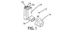
図1は、本発明の好ましい態様に従った手動操作式の計量式用量吸入器12のメイン本体10を示している。メイン本体のマウスピース16に固定されうるマウスピースキャップ14を有している。 FIG. 1 shows a
メイン本体はキャニスタチャンバ18を有しており、その中にはキャニスタ20(図7A)をスライド収容できる。キャニスタ20は、大略的に円筒状の主側壁24を有し、テーパ部26によって頭部28へとつながっている。頭部28は実質的に平坦な下面30を有し、下面30は外環状駆動面32を有し、外環状駆動面32は、後述されるように、用量カウンタ36のアクチュエーションピン34に連結してそれを動かすように設計されている。下面30から中央に軸方向に延在するバルブ軸38があり、バルブ軸38は、吸入器12のメイン本体10のバルブ軸ブロック40に密着して係合するよう設計されている。バルブ軸ブロック40は、キャニスタ20の内容物、特に、活性薬剤や推進剤を吸入器メイン本体12の空気出口46に向かって導くために、ノズル44につながる経路42を有する。キャニスタ20と吸入器12のメイン本体10の内壁50との間にあるギャップ48によって、メイン本体10の開口上面52が、空気出口46のある経路54を通じて貫通して、吸入器12への空気口を形成していることは注目されるべきであり、それゆえに、ノズル44にあるキャニスタ内容物は空気経路54を通じて使用者によって吸い込まれた空気と混合し、ともに空気出口を通じて使用者の口中に流れるようになる(不図示)。 The main body has a
ここで用量カウンタ36が説明される。用量カウンタ36は、メイン本体10に組み込まれた戻りばね56によって下から上に付勢されるアクチュエーションピン34を含む。
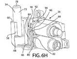
図4A、6H及び8Aに最も示されるように、ピン34は側面58、60を有し、側面58、60は、メイン本体10の用量カウンタチャンバ66にあるガイド面62、64に対応してその間をスライドするよう設計されている。同様に終端面68は、用量カウンタチャンバ66に形成された末端70で係合するよう設計されて、ピン34の上方への動きを制限する。ピン34は、上部72を有し、上部72は円環筒状であり、用量カウンタチャンバ66からキャニスタチャンバ18を分離する分離壁76を通って形成される開口74を通って延在する。ピン34の上部72は、キャニスタ20の外環状駆動面32に係合するよう配置された平坦な上面78を有している。The
As best shown in FIGS. 4A, 6H and 8A,
アクチュエーションピン34は、ドライブ又はアクチュエータ歯止め80と一体的に形成される。アクチュエータ歯止め80は、大略的に逆U字型であり、2つの並行する互いに離間したアーム82、84を有し、アーム82、84はアクチュエーションピン34の下部から延在しており、各々は末端88で、アーム82、84と実質的に垂直方向に延在する歯止め歯部材90の逆端を保持している。そのために、用量カウンタ36の増加ドライブシステム96又はラチェットメカニズム96のラチェットホイール94の11個のドライブ歯92の各々を引っ張るための「鞍状」ドライブと考えられるものが提供される。例えば図10Bに示されるように、歯止め歯部材90は、ドライブ歯92に係合するよう配置された鋭い下部長手側端98を有し、この係合によってもたらされる端‐面接触は、アクチュエータ歯止め80の非常に正確な位置と、それによるラチェットホイール94の回転位置を提供する。 The
用量カウンタ36はまた、図4A及び6Aに示されるように、テープリールシャフト106に固定されたラチェットホイール94を受ける第一シャフト104と、第一シャフト104と平行して離間しており、テープストックボビン110をスライド可能かつ回転可能な状態で受ける第二シャフト(又はスプリットピン)108とを有するシャーシ102を含む、シャーシプレアッセンブリ100を有する。 The
図6Bに示されるように、吸入器が全く使用されていない時、テープ112のほとんどはテープストックボビン110上に巻かれ、テープ112は、キャニスタ20内に残る用量を示す数字を示す、テープに沿って等間隔に付された一連の数字114を有している。吸入器が繰り返し使用されるにつれて、ラチェットホイール94は、キャニスタ20によるアクチュエーションピン34の動作に起因するアクチュエータ歯止め80によって回転させられる。テープ112は、第二シャフト108から漸増的・段階的に、テープリールシャフト106に巻かれる。テープ112はシャーシ102のテープガイド116に沿って通過し、それによって、数字114は、用量マーカー132が作られ又は付けられている用量カウンタチャンバカバー120にある窓118を通して、表示される。 As shown in FIG. 6B, when the inhaler is not used at all, most of the
図6A及び6Dに示されるように、第二シャフト108は2つの分枝124、126に分岐している。分枝124、126は互いに離れる方向に付勢されている。これら分枝は、それぞれの分枝の、第二シャフト108上の半径方向逆側に、摩擦又はコントロール部品128、130を備えられている。各コントロール部品は、各分枝124、136に沿って長手方向に延在しており、長手方向に延在する摩擦面132、134を有している。摩擦面132、134は、第二シャフトの長手方向軸に実質的に平行に延在し、テープストックボビン110の内側の実質的に円筒形のボア136に内側係合するのに適している。この、ボア136とコントロール部品128、130との間で提供されるコントロール設計は、テープストックボビン110に良好な回転コントロールをもたらす。ゆえに、例えば吸入器が落下した時などに、望まないテープの緩みなどが生じることがない。テープストックボビン110を緩ませ、この摩擦力を克服するために必要なテープの力は、約0.1Nである。 As shown in FIGS. 6A and 6D, the
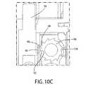
図6Dや、図6G及び10Aから10Fに見られるように、シャーシ102は、そこに弾性的かつ実質的に固定して配設された逆回転防止歯138又はカウント歯止め138を備えている。下記で説明され、また、図10Aから10Fに見られるように、アクチュエーションピン34が、キャニスタ20内部の計量バルブ(不図示)を発射させるように完全に圧縮された時、アクチュエータ歯止め80は、ラチェットホイール94の歯の一つ92を引き下げ、図6Dに示されるようにホイール94を逆時計回りに回転させ、そうして一つの歯92がカウント歯止め138を飛んで過ぎ、ゆえに、1用量分が使用されたことを示すように、用量カウンタチャンバ120上の用量マーカー122に関する増加方向の距離分だけテープ112が巻かれる。 As seen in FIG. 6D and FIGS. 6G and 10A to 10F, the
図10Bを参照すると、ラチェットホイール94の歯は、平坦面140、142の間に、半径0.1mmの先端143を有している。ラチェットホイール94は、基準面220(図9)より0.11mm上である中心軸145を有している。逆回転防止歯138の先端/ノーズ面147は基準面220より0.36mm上に位置している。逆回転防止歯の先端ノーズ面147の間の垂直距離(すなわち、図9の基準面を横切る方向)は、ホイール94の中心軸145から0.25mmである。隆起面144は側方向長さが0.20mmで平面145´自体の垂直方向長さが1mmであり、隆起表面の幅が1.22mm(軸145の方向)であり、隆起表面144の先端149は軸145の垂直方向下3.02mmであり、平面145´は軸145から横向きに2.48mm離間して(すなわち基準面220と平行)いる。ピン34(図6H)の先端面78は、アクチュエータ歯止め80とピン34がスタート形態にある時、基準面220(図9)から11.20mmである。バルブステム22の長さは11.39mmであり、キャニスタ20のドライブ面32は、キャニスタが作動されるのを待機してレスト形態である時、基準面220の上11.39mmである。すなわち、この設定では、キャニスタ20とピン34の間のクリアランスは0.19mmである。 Referring to FIG. 10B, the teeth of the
図10A及び10Bは、アクチュエータ歯止め80と、スタート位置にあって、ピン34の平坦な先端78が未だキャニスタ20の外環状駆動面32によって係合していないか、又は少なくともキャニスタが圧縮されて押し下げられていない状態である、ラチェットホイール94とカウンタ歯止め138を示している。 10A and 10B show that the
この“スタート”位置では、カウンタ歯止め138はラチェットホイール94の一つの歯92の非逆回転面140と係合している。アクチュエータ歯止めの下部側端98はバルブブロック40の底面又は肩41を通る基準面220より上1.33mm(距離「D」)にある。基準面220は、吸入器12のメイン本体10の主軸「X」に垂直であり、バルブ軸ブロックボア43の中心と同軸で、キャニスタが発射される時、吸入器12のメイン本体10でのキャニスタ20のスライド方向と平行である。 In this “start” position, the
図10Bに示されるように、この構造の有利な特徴は、歯止め歯/アクチュエータ90が、吸入器12が吸入の為に使用されない時には、補充的な逆回転防止部材として作用することである。特に、吸入器12が偶然に落下して、用量カウンタ36が揺動し、ホイール94が図10Bに示されるように時計回り(逆回転)に回転しようとすれば、歯の裏面140が係合して歯止め80の歯部材90によってブロックされる。つまり、例えそのような揺動で後退防止ドライブ歯138が一時的に折れたり乗り越えられたりしても、正しい位置に保持するためにホイール94の望まない逆回転は回避され、それゆえに用量カウンタ36は正しい用量指示を提供し続ける。 As shown in FIG. 10B, an advantageous feature of this construction is that the pawl /
図10Cは、アクチュエータ歯止め80が、キャニスタ20によってピン34で、歯止め歯部材90の側端98がちょうど一つの歯92に係合する位置まで押圧されている形態を示しており、すなわち、さらなるピン34の押圧がホイール94を回し始めるだろう。これは「リセット」位置又は形態と称される。この形態では、アクチュエータ80の下部側端98が、基準面220より0.64mm大きい。 FIG. 10C shows a configuration in which the
図10Dは、アクチュエータ歯止め80が図10Cで示されたよりも低い位置にある形態であって、ノズル44を通じて活性薬剤と推進剤とを放出するために、まさにこの位置でキャニスタ内部の計量式用量バルブ(不図示)が発射する形態を示している。この形態では、カウンタ歯止め138は、図10Dの形態では係合していた同じ歯92の裏面140から非常に僅かに離間していることに注目すべきである。図10Dに示される形態は、「発射」形態として知られる。この形態において、アクチュエータ80の下部側端98は基準面220の0.47mm下である。 FIG. 10D shows a configuration in which the
図10Eは、シークエンスのさらなるステップを示しており、「カウント」形態と呼ばれ、当該形態では、アクチュエータ歯止め80が、二つの歯92の間の円周方向の角度分だけラチェットホイール94を回転させており、カウンタ歯止め138は、歯92の一つの前面142に沿って進み、弾性的に歯を飛び越えて、次の歯の裏面140と係合したところである。さらにこの「カウント」形態では、ピン34の十分に長いストローク運動が、用量カウンタ36のテープ112の、1用量分のカウントダウンをもたらしている。この形態では、アクチュエータの下部側端98は基準面220の0.95mm下である。さらにこの位置では、端98も含む一般的なアクチュエータ80は、発射形態から0.48mm下である。カウント形態は発射形態よりもさらに先で起こるにも関わらず、カウントは非常に高信頼性を有することが見いだされており、100万中50分の1を超えない割合である。これは少なくとも部分的には、運動量効果と、いくつかの実施態様では、内部計量バルブが発射するときにキャニスタが使用者に何らかの背圧を発出することによっている。 FIG. 10E shows a further step in the sequence, referred to as the “count” configuration, in which the
図10Fの形態において、歯止め80はキャニスタ20によってピン34で、歯92の一つから離合する位置へとさらに圧縮され、アクチュエータ歯止め80はこの離合において、アーム84の一つとシャーシ102(図6G参照)の隆起表面144との係合によってアシストされ、この離合の点(「エンド」形態と呼ばれる)においては、カウンタ歯止め138は2つのドライブ歯92の正確に中間か、実質的に中間に位置している。すなわちこの有用性は、望まれないダブルカウントやノーカウント(カウントされないこと)のあらゆる可能性を最小限の機会とすることを意味している。エンド形態において、アクチュエータの側端98は基準面の1.65mm下である。図10Fに示される「エンド」形態を過ぎたさらなるアクチュエータ歯止め80とピン34のどんな圧縮も、用量カウンタ36によって表示されるテープ112の位置に何の影響も与えない。なぜなら、図10Fに示されたよりも下の位置にあるときには、アクチュエータ歯止め80はラチェットホイール94から離合しているからである。 In the configuration of FIG. 10F,
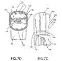
図7C及び7Dに示されるように、主本体10の内壁50は、メイン本体内側に沿って長手方向に延在し、開口74に隣接する2段階の支持レール144が備えられている。図7Bに示されるように、半径方向逆側に2段階レール146がまた備えられており、この半径方向逆側とは、垂直面(不図示)が、実質的に直接に第一レール144、開口74、バルブ軸ブロック40の中央開口148(ここにキャニスタ25が位置する)、及び第二の2段階レール146を通りうるという意味である。図7Aに示され、図7Bに概略的に示されるように、レール144、146は、キャニスタ20とレール144、146の間に、半径方向にほぼ正確に0.3mm、典型的には約0.25mmから0.35mmの範囲で、最大クリアランスを備える。この面におけるこのクリアランスは、キャニスタ20が、アクチュエーションピン34から離れる方へ向かって、この面で後ろ向き又は前向きのみに揺動しうることを意味している。相対的に小さな距離とこの構成はすなわち、キャニスタがぐらつき、また、アクチュエーションピン34の高さを変化させて、用量カウンタ36の正確性を望まず改変してしまうことを回避できる。 As shown in FIGS. 7C and 7D, the
吸入器12の内部で自由なキャニスタの動きを許容しながらも、過度の揺れを回避するために、内壁50の辺縁の周辺に離間して設けられている全てのレール144、146、150、152、154について、キャニスタ20周りの最大クリアランスがほぼ正確に0.3mmになるように、メイン本体10の内壁50は、2つのさらなる2段階レール150と、内壁50から内側に異なる一定の半径方向量で延在している2ペアのレール152、154とを備えている。例えば2段階レールがキャニスタチャンバ18の出口端156近くの第一部分を有し、当該第一部分は実質的に一定の半径又は内向きに延在する幅を有し、第一のステップ160はレールの第二の段階162に続き、第二部分102は第一部分156よりも小さい半径又は内向きの延在範囲を有し、第二ステップ164の最後ではレールはメイン内壁50の主表面に結合していることが、図7Cから明らかになるであろう。 All
吸入器12の組み立て方法が説明される。 A method for assembling the
図8Aを参照すると、吸入器12の主本体10は、互いに連結されて示された形態となる、2又はそれ以上のプラスチックの成形品で形成されている。 Referring to FIG. 8A, the
図8Bに示されるように、アクチュエータ歯止め80とピン34が、用量カウンタチャンバ66にあるピン受けエリア166の中の位置へとまっすぐ前向きに入れられる。また、ピン34とアクチュエータ80は、ピン34が開口74を通って出るまで持ち上げられる。 As shown in FIG. 8B, the
次に、戻りばね56がピン34の下に挿入されて、ばね56の大略的に円筒形で環状の下部端168が、ピンセットかピンセット様の組み立て工具(不図示)で動かされて、用量カウンタチャンバ66にあるばね受け172の棚170に係合させられる。ばね受け172はU字型であり、棚170はU字型であってその下に形成された凹部174を有する。図4B、4C及び12に示されるように、棚170は、ばね168の下端を、組み立て工具(不図示)を用いて棚の上の位置に動かすときにアシストするように配置された3つの面取り面176、178、180を含んでいる。ばね168の下端を一度位置すれば、組み立て工具(不図示)は、ばね56の下端168の下の凹部174を少なくとも部分的に通じて、簡単に取り除かれる。 Next, the
テープ112はテープストックボビン110に一端(不図示)が付けられており、ボビンの六角形のソケット204(図6B)に係合している六角形の出力シャフト202を有するモータ200(図13)によってボビン上に巻かれている。巻いている間、テープはセンサ206でモニターされており、モニター206はカメラまたはレーザースキャナの形式であって、モータ200のためにコンピュータコントローラ205へデータをフィードする。コントローラ205はテープ112を横切るラインの形状である3つの位置マーカ210を認識し、テープ112がほぼ全部がボビンに巻かれた時に、テープ112の遠い方の端が例えば接着によってテープリールシャフト106に固定されるように、モータ202を止める。前記コントローラ205はまた、センサ206に観察されるピクセルで表されたテープサイズマーカ214を認識し、例えば、120や200といったテープ上の数字の数114などのテープ112の詳細をデータストア217のストックシステムに記録する。続いて、テープリールシャフトがライン210の適切な位置まで巻かれる。当該位置は、ボビン110及びリールシャフト106が第二シャフト108及び第二シャフト104の上にスライド挿入され、吸入器112が完全に組み立てられた時に、プライミングドット(一点破線)216が窓118に位置することになる位置である。実施形態では、ボビン110とリールシャフト106は、テープ112がリールシャフト106に固定される前にシャフト108、104にスライド挿入されてもよく、それから、リールシャフトがプライミングドット216に位置合わせするように巻かれるのでもよい。 The
続いて、図6Bに示されるシャーシプレアッセンブリ100の組み立てられた用量カウンタ部品が、図8Cに示されるように、用量カウンタチャンバ66の主本体10に形成されたピン182、184、186をシャーシ102に形成された開口又はスロット188、190、192に通して、ピン182、184、186が開口又はスロット188、190、192に貫通する(少なくとも入る)ようにして、用量カウンタチャンバ66に挿入される。シャーシ102はメイン本体10に向かって相対的に確実に押し込まれ、そして、ピン182、184、186は熱かしめされる。ゆえに、シャーシ102はこの後この位置で主本体に対して非常に堅固に保持され、動くことができなくなる。ゆえに、用量カウンタ36の高い正確性が提供される。次に、図8Dに示されるように、用量カウンタチャンバカバー120が用量カウンタチャンバ66にかぶせ合され、プライミングドット216が窓から表示されている状態で、例えば溶着によって所定位置に固定される。 Subsequently, the assembled dose counter component of the
最初の使用のために吸入器12を準備する時、ユーザはキャニスタを3回押圧することによって吸入器を準備することができる。3回の押圧はプライミングドット216があった窓118に、テープの最初の数字114をもたらす。図8Dに示された数字「200」は、キャニスタ20及び吸入器12から吐出される薬剤200用量分が残存していることを表示している。 When preparing the
図8D及び図5に示されるように、開口したドレイン孔194が、吸入器の主本体10の下部表面198にある半円の切欠き又は凹部形状196で、用量カウンタチャンバ66の底部に設けられている。さらに、例えば非衛生的な状況に遭遇した後や単なる選択事項として、ユーザ(不図示)が吸入器の主本体10を洗おうと決めた場合、ドレイン孔194は、用量カウンタチャンバ66の内側からの水の初期的な排出と、またそれゆえに用量カウンタチャンバ66内の水又は何らかの水性の物質の蒸発とを可能とするので、窓118が望まず曇ることがない。 As shown in FIGS. 8D and 5, an
図14は、用量カウンタ36をデザインするためのコンピュータシステム、特に、基準面220(図9)に関するアクチュエータの下部側端98、つまり、吸入器12のラチェットホイール94、シャーシ102及び吸入器12が完全に組み立てられた時には主本体10のスタート、リセット、発射、カウント及びエンド位置の吸入器の一連の生産物における平均位置と標準偏差を表す分布を計算するためのコンピュータシステム230を示す。コンピュータシステム230はデータストア232、CPU234、入力デバイス236(例えばキーボード又はコミュニケーションポート)及び出力デバイス238(例えばコミュニケーションポート、ディスプレイ画面及び/又はプリンタ)を含む。使用者は、入力デバイス236を通じてデータを入力することができる。データは、CPU234によって、一連の、所与の平均値と標準偏差がセットされた用量カウンタ位置を備え、あらゆる運動量/慣性の影響と所与のタイプのキャニスタを発射させるときに生じる計量バルブの使用者背圧減少効果とを考慮して、様々な用量カウンタが製造されるとき、カウント失敗率を予測するための数学的な計算において使用されてもよい。コンピュータシステム230はこのように分布をデザインするために数学的に使用される。用量カウンタ36とキャニスタ20でここに説明された吸入器12のために、図11に示されるように分布がデザインされる。X軸は基準面220上のアクチュエータ80の下部側面98の距離を示しており、Y軸は分布を示している。曲線240は、スタート位置は基準面200の上、平均1.33mm(標準偏差は0.1mm)であることを示しており、曲線242は、リセット位置は基準面220の上、平均0.64mmであることを示しており、曲線244は、発射位置は基準面220の下0.47mm(標準偏差は0.141mm)であることを示しており、曲線246は、カウント位置では基準面220より下平均0.95mm(標準偏差は0.080m)であることを示しており、曲線248は基準面220より下平均1.65mm(標準偏差は0.144mm)であることを示している。 FIG. 14 shows a computer system for designing the
図15から20は、本発明に沿った好ましい態様を示しており、図1から14を参照して説明された態様を変更したものである。これらの図では、以前の図において用いられた符号は同等の要素を意味するよう用いられる。吸入器12は次の点を除いて図1から14と同様である。 15 to 20 show a preferred embodiment in accordance with the present invention, which is a modification of the embodiment described with reference to FIGS. In these figures, the symbols used in the previous figures are used to denote equivalent elements. The
第一に、ラチェットホイール94のドライブ歯92が図1から14と異なる輪郭を有する点で変更点がある。この態様ではラチェット歯94は11ではなく9だけである。 First, there is a change in that the
さらに、図18C及び19Cに示されるように、第二のシャフト108のフォーク124、126上のコントロール部材128、130が、図6Fに示されたコントロール部材128、130の輪郭と異なるテーパ形状を有している。いずれにしても、いずれの輪郭も図15から20の態様においても使用され得る。 Further, as shown in FIGS. 18C and 19C, the
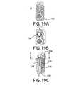
さらに、図15に示されるように、テープストックボビン110は、部分的にそこに延在する波状の、内部に面した大略的に円筒形の係合表面300を有する。係合表面300は、それに忠実に沿うストックボビン110の長手方向長さに垂直な横断面301を有する。この横断面301は図16にも見られ、10の一定間隔の凹面と10の凸状壁部材304の一連を形成しうる。凸状壁部材304は凹部302の間に等間隔である。各凹部302は半径0.2mmである。各凸状壁部材304もまた半径0.2mmである。最後に、横断面301もまた、凹部302と凸状表面304の全ての曲面状壁部材の間の平坦な壁部分306も含む。横断面301の形状はゆえに、凹部302及び凸状壁部材304、平坦壁部分306の半径と、10の凹部302と凸状壁部材304とがあるという事項によって定義される。 Further, as shown in FIG. 15, the
係合表面300の小半径、つまり、凸状壁部材304と逆の先端の間、は2.46mmである。係合表面300の大半径、つまり、凹部302の最外部分の間は2.70mmである。スプリットピン(第二シャフト)108のフォーク124、126の変形されていない先端から先端への最大直径、つまり、コントロール要素128、130の最大径方向長さの領域においては3.1mmであり、すなわち、ひとたびストックボビン110がスプリットピン108に組み付けられると、スプリットピン108に関してストックボビン110の全ての回転配置において、フォーク124、126は弾性的に圧縮されていることが理解される。図18C及び19Cの横断平面においてフォーク124、126の間の最小のギャップは、スプリットピン108が変形されておらず挿入前の状態であるとき、1mmである。スプリットピン108が最大圧縮されているとき、図18Aから18Cに示されるように、コントロール要素128、130が凸状壁部材304の先端に係合されるように示されるとき、フォーク124、126の先端310、312の間のギャップ308は0.36mmである。一方、スプリットピン108が、図19Aから19Cまでに示されるように最小の圧縮(ストックボビンに入れられた後)であるとき、コントロール要素128、130が凹部302内に留まっているとき、フォーク124,126の先端310、312の間のギャップは0.6mmである。コントロール部材128、130は、半径がまた0.2mmで外向きに放射状になっており、完全に全体が接触して、ガタつきなく、凹部302に固定して又は接触しないで、凹部302に留まっている(少なくとも、テーパ状のコントロール要素がその最大放射方向位置にある状態の、スプリットピンの軸方向位置において)。コントロール部材128、130の半径は、ゆえに、実質的に凹部302の半径と同じである。 The small radius of the
一方、図18B及び19Bはストックボビン110とスプリットピン108の同軸である軸に沿った端面図であり、図18A及び図19Aは断面図であることが認められるであろう。図19Aは、図19CのA−A´平面における断面であり、図18Aは同じ平面の断面であるが、言うまでもなく、スプリットピン108に関して回転したストックボビン110を伴うものである。 On the other hand, it will be appreciated that FIGS. 18B and 19B are end views along a coaxial axis of the
吸入器12が使用され、ラチェットホイール94が使用用量をカウントするために回転するにつれて、ストックボビンは回転に抵抗する回転位置を通って増加的に回転する(つまり、そのような回転位置でのスプリットピン108の増加する圧力による)、そして、その回転における回転位置に進められる(つまり、そのような回転位置でのスプリットピン108の減少する圧力による)、そしてこのことが、図19Aから19Cではスプリットピンのコントロール部材128、130が凹部302の位置しているのと同じように、ストックボビン110を次の位置へと段階的に進めることになる。この機能は第一に、ストックボビンが使用中に要求に応じて巻き出されることを許容する、しかしまた、移動中に吸入器12が例えば固い表面の上などに落とされたとしても、テープ112が緩むことを回避できる。このことは極めて有利である、なぜなら、テープ11は、キャニスタの用量数に関して不正確な読みを与えるかもしれない位置に動くことが回避されるからである。 As the
図18C及び19Cに示された2つの形態の間の、放射状方向におけるフォークの拡張と加圧の間、フォーク124、126はスプリットピン上の点316の周りを回転する、その位置にはフォーク124、126がともにやってくる。この回転運動はフォーク124、126と係合表面300との間には著しい摩擦のないカム作用があることを意味する、しかしながら、それにも関わらず、係合表面300とフォーク124、126とによって形成されるレギュレータによって提供される弾性力はテープの巻き出しを調節することができ、そして、移動中や吸入器12が落とされた場合に、簡単には巻き出し(緩み)が生じないようになる。テストの間に、0.3から0.4Nの力が、ストックボビン110でレギュレータを克服するためにテープ112に与えられねばならないことが見いだされた。図19Cに示される形状を有するコントロール部材128では0.32Nが得られ、図6Fを参照して説明されて示されたコントロール部材128の形状では0.38Nが得られた。これらの力は、上述された0.1Nの力よりも実質的に大きく、テープの望まない動きが、吸入器が固い表面上に落とされた時でも、実質的に回避される。図15から20の改変された配置は、この力を「定常的に」提供することがない、ゆえに、テープ112が用量カウンタの他の部材を通過するときのテープ112の望まない大きな摩擦は生じることがない。なぜなら、レギュレータでの弾性力の漸増的な特性によって、テープ112は固定されたシャーシ部材上をスライドしながら、漸増的に弛緩することが可能だからである。 During fork expansion and pressurization in the radial direction between the two configurations shown in FIGS. 18C and 19C, the
10の凹部302と凸状壁部材304を有する代わりに、例えば8や12など異なる数も用いられ得る。しかしながら、偶数が好ましい、なぜなら、特にコントロール部材128、130が設けられており、ゆえにコントロール部材128、130の全部が同時に拡張し、縮小しうるからである。しかしながら、3以上のフォークを有する他の配置も考えられ、凹部/凸状壁部材の数は、同時に拡張/縮小するという機構を維持するためにフォークの数で割り切れる整数とされることもできる。例えば、3つのフォークを有し、9、12、15の凹部/凸状壁部材を用いることが考えられる。 Instead of having ten
ストックボビン110の内側に係合表面300を有する代わりに、係合表面300は、フレキシブルな外部脚/歯止めによって係合されるように、ストックボビン110の外側に配置されるのでもよい。 Instead of having an
係合表面300とフォーク124、126によってもたらされるレギュレータは、ラチェットホイール94の場合のように一方向のみのストックボビンの回転を許容するものではないことは留意されるべきである。両方向、すなわち前方及び後方への回転が可能である。このことは、組み立ての際、ストックボビン110は、ボビン100、シャフト106及びテープ112がキャリッジ112上に取り付けられる間に又はその後に、所望に応じて後方に巻き戻されうることを意味している。 It should be noted that the regulator provided by the
スプリットピン108を含むストックボビン110及びキャリッジ102はいずれも、ポリプロピレン材料で成型される。 Both the
図16からは、横断面の形態301は六角形のソケット204の中でシンメトリーでないことが見て取れるだろう。このことは、六角形のソケット204と六角形状と干渉することなくフィットするために横断面301のサイズと配置を所望のものとしつつも、六角形のソケット204が使いやすいサイズに維持されることを許容する。また、製造において成型することを可能にする。 From FIG. 16, it can be seen that the
図17に示されるように、ストックボビン110は一連の4つの円周状のリブ330をその内側にそれに沿う間隔を開けて有する。これらは、ストックボビン110を、成型の間、成型ツールの正しい側に保持しておく。 As shown in FIG. 17, the
図21と22は、患者の吸入のために、計量された用量でドライパウダー薬剤を吐出するための吸入器510の発明に沿った、好ましい態様を示す。吸入器510はEP−A−1330280の図1から16に開示されたもので、その内容はここに全体的に参照によって引用される、しかし、用量カウンタ516のストックボビン110と第二シャフト108は、本願の図15から20のもののように改変されている。すなわちドライパウダー吸入器510は、大略的にハウジング518と、ハウジングに受容されるアッセンブリ512を含む(図21を参照)、ハウジング518は、患者の吸入のために開口端522とマウスピース524(図25)を有するケース520と、ケース520に取り付けられて開口端522を閉じるキャップ526と、そして、マウスピース524をカバーするためにケース520に枢動可能に取り付けられたカバー528とを含む。図22に示されるように、吸入器510はまた、アクチュエータばね569、開口572のある第一ヨーク566、冠部574のあるべローズ540、貯蔵部514、ホッパー542のある第二ヨーク568、及び、そこに備え付けられた用量カウンタ516を含み、ケース520は、用量カウントテープマーク5128を見るためにそこに透明な窓5130を有している。用量カウントシステムはまた、マウスピースカバー528に備えられ、開及び閉位置の間でカバー528と共に可動である、二つのカム570を含む。カム570の各々は、ケース520の外側に延在するヒンジ584が、カバー528の第一の凹部584へと貫通し、受容されることを許容するための開口580を含む。カム570はまた、外側向きに延在し、カバー528の第二の凹部588に受容されるボス586を含み、ゆえに、カバー528はヒンジ582に関して枢動し、カム570はヒンジ582に関してカバー528と共に動く。EP−A−1330280で説明されたように、カム570は第二のヨーク568を上下に動かすためにカムサポータ578に作用し、それで、歯5136のある第二のヨーク568の歯止め5138の係合によって、用量カウンタを操作する。吸入器の残りの部材は、EP−A−1330280で説明されたように設けられ、操作される。 FIGS. 21 and 22 show a preferred embodiment along the invention of an
すなわち用量カウントシステム516は、印刷された連続数の、又は他の適切なマークを有し、ハウジング18(図22参照)に備えられた透明の窓5130に一致する、リボン又はテープ5128(図23、24)を含む。用量カウントシステム516は、回転可能なストックボビン110(上述)と、一方向に回転可能なインテックススプール5134と、リボン5128とを含み、リボン5128は、ボビン110上で回転し、ボビン110に支持され、スプール5134に固定された第一端5127を有しており、スプール5128ではリボン5128はボビン110から巻き出されて、マークは、スプール5134が回転し前進するにつれて、連続的にディスプレイされる。図23及び24ではボビン110の波状の係合表面300は明瞭性の観点から示されていない。 That is, the
スプール134は、貯蔵部514からの薬剤用量の送達に作用するヨーク566、568の動きにつれて回転して、リボン5128上の数字は、吸入器510によって吐出された用量を表示するために前進する。リボン5128は、スプール5134の回転に従って、数字又は他の適切なマークを、増加又は減少させるように設計されうる。例えば、リボン5128は、吸入器510に残存している用量の数を表示するために、スプールの回転に従って、数字又は他の適切なマークが減少するように設計され得る。代替的に、リボン5128は、吸入器10によって吐出された用量の数を表示するために、スプール5134の回転に従って、数字又は他の適切なマークが増加するように設計されてもよい。 The spool 134 rotates with the movement of the
インデックススプール5134は、放射状に延在する歯5136を含み、当該歯は、インデックススプール5134を回転させ又は前進させるためのヨークの動きに従って、第二ヨーク568のカムサポータ578から延在する歯止め5138によって係合されている。より特定的には、歯止め5138は、歯5136と係合し、インデックススプール5134を、マウスピースカバー528が閉じられ、ヨーク566、568がハウジング518のキャップ526に逆戻りしているときのみ、インデックススプール5134を前進させるように形成され、配置されている。 The
用量カウントシステム516はまた、用量カウントシステムをホッパ542に固定するシャーシ5140を含み、ボビン110とインデックススプール5134を受けるためのシャフト108、5144を含む。図15から20を参照して上述されたように、ボビンシャフト108はフォーク状に分岐していて、ボビン110の内側の波状係合表面300と係合することによって、シャフト108上のボビン110の回転への弾性抵抗を作り出す放射状に突出する突起5146を含む。クラッチばね5148は、インデキシングスプール5134の端に受けられ、スプール5134の回転を一方向のみに許容するようにロックされている。 The
特許法下で解釈される添付の請求項によって定義される発明の射程から解離することなく、上記に示され説明された態様には、様々な改変が加えられ得る。 Various modifications may be made to the embodiments shown and described above without departing from the scope of the invention as defined by the appended claims as interpreted under patent law.
Claims (4)
Translated fromJapanese当該テープストックボビンは支持シャフトに支持され、支持シャフト周りの回転のための内部ボアを有し、
ボア及び支持シャフトの少なくとも一方は、ボア又は支持シャフトの長手方向軸に平行な方向に延在する摩擦端を有する、放射状に延在する突起部を有し、
前記突起部は、ボア及び支持シャフトの他方の波状係合表面と弾性的に付勢され、長手方向に延在する相互的な摩擦相互作用で摩擦係合する、用量カウンタ。A dose counter for an inhaler, comprising a display tape arranged on thetape reel shaft to be moved incrementally from a tape stock bobbin;
Thetape stock bobbin is supported on a support shaft and has an internal bore for rotation around the support shaft;
At least one of the bore and the support shaft has a radially extending protrusion having a friction end extending in a direction parallel to the longitudinal axis of the bore or support shaft;
The dose counter is resiliently biased with the other wavy engagement surface of the bore and support shaft and frictionally engages with a longitudinally extending frictional interaction.
Applications Claiming Priority (4)
| Application Number | Priority Date | Filing Date | Title |
|---|---|---|---|
| US34576310P | 2010-05-18 | 2010-05-18 | |
| US61/345,763 | 2010-05-18 | ||
| US41765910P | 2010-11-29 | 2010-11-29 | |
| US61/417,659 | 2010-11-29 |
Related Parent Applications (1)
| Application Number | Title | Priority Date | Filing Date |
|---|---|---|---|
| JP2014042633ADivisionJP5820006B2 (en) | 2010-05-18 | 2014-03-05 | Dose counter for inhaler, inhaler and its shaft |
Publications (2)
| Publication Number | Publication Date |
|---|---|
| JP2015231584A JP2015231584A (en) | 2015-12-24 |
| JP6227608B2true JP6227608B2 (en) | 2017-11-08 |
Family
ID=44971401
Family Applications (14)
| Application Number | Title | Priority Date | Filing Date |
|---|---|---|---|
| JP2013510519AActiveJP5497964B2 (en) | 2010-05-18 | 2011-05-18 | Dose counter for inhaler, inhaler and its shaft |
| JP2014042630AExpired - Fee RelatedJP5933607B2 (en) | 2010-05-18 | 2014-03-05 | Dose counter for inhaler, inhaler and its shaft |
| JP2014042633AExpired - Fee RelatedJP5820006B2 (en) | 2010-05-18 | 2014-03-05 | Dose counter for inhaler, inhaler and its shaft |
| JP2014042629AExpired - Fee RelatedJP5896487B2 (en) | 2010-05-18 | 2014-03-05 | Dose counter for inhaler, inhaler and its shaft |
| JP2014042632AExpired - Fee RelatedJP5820005B2 (en) | 2010-05-18 | 2014-03-05 | Dose counter for inhaler, inhaler and its shaft |
| JP2014042627AExpired - Fee RelatedJP5806354B2 (en) | 2010-05-18 | 2014-03-05 | Dose counter for inhaler, inhaler and its shaft |
| JP2014042628AExpired - Fee RelatedJP5806355B2 (en) | 2010-05-18 | 2014-03-05 | Dose counter for inhaler, inhaler and its shaft |
| JP2014042631AActiveJP5900932B2 (en) | 2010-05-18 | 2014-03-05 | Dose counter for inhaler, inhaler and its shaft |
| JP2014042634AActiveJP5820007B2 (en) | 2010-05-18 | 2014-03-05 | Dose counter for inhaler, inhaler and its shaft |
| JP2015193578AExpired - Fee RelatedJP6273242B2 (en) | 2010-05-18 | 2015-09-30 | Dose counter for inhaler, inhaler and its shaft |
| JP2015193577AActiveJP6227608B2 (en) | 2010-05-18 | 2015-09-30 | Dose counter for inhaler, inhaler and its shaft |
| JP2015193579APendingJP2016025944A (en) | 2010-05-18 | 2015-09-30 | Dose counter for inhalator, inhalator and shaft thereof |
| JP2015256386AActiveJP6301904B2 (en) | 2010-05-18 | 2015-12-28 | Dose counter for inhaler, inhaler and its shaft |
| JP2017149821AActiveJP6564820B2 (en) | 2010-05-18 | 2017-08-02 | Dose counter for inhaler, inhaler and its shaft |
Family Applications Before (10)
| Application Number | Title | Priority Date | Filing Date |
|---|---|---|---|
| JP2013510519AActiveJP5497964B2 (en) | 2010-05-18 | 2011-05-18 | Dose counter for inhaler, inhaler and its shaft |
| JP2014042630AExpired - Fee RelatedJP5933607B2 (en) | 2010-05-18 | 2014-03-05 | Dose counter for inhaler, inhaler and its shaft |
| JP2014042633AExpired - Fee RelatedJP5820006B2 (en) | 2010-05-18 | 2014-03-05 | Dose counter for inhaler, inhaler and its shaft |
| JP2014042629AExpired - Fee RelatedJP5896487B2 (en) | 2010-05-18 | 2014-03-05 | Dose counter for inhaler, inhaler and its shaft |
| JP2014042632AExpired - Fee RelatedJP5820005B2 (en) | 2010-05-18 | 2014-03-05 | Dose counter for inhaler, inhaler and its shaft |
| JP2014042627AExpired - Fee RelatedJP5806354B2 (en) | 2010-05-18 | 2014-03-05 | Dose counter for inhaler, inhaler and its shaft |
| JP2014042628AExpired - Fee RelatedJP5806355B2 (en) | 2010-05-18 | 2014-03-05 | Dose counter for inhaler, inhaler and its shaft |
| JP2014042631AActiveJP5900932B2 (en) | 2010-05-18 | 2014-03-05 | Dose counter for inhaler, inhaler and its shaft |
| JP2014042634AActiveJP5820007B2 (en) | 2010-05-18 | 2014-03-05 | Dose counter for inhaler, inhaler and its shaft |
| JP2015193578AExpired - Fee RelatedJP6273242B2 (en) | 2010-05-18 | 2015-09-30 | Dose counter for inhaler, inhaler and its shaft |
Family Applications After (3)
| Application Number | Title | Priority Date | Filing Date |
|---|---|---|---|
| JP2015193579APendingJP2016025944A (en) | 2010-05-18 | 2015-09-30 | Dose counter for inhalator, inhalator and shaft thereof |
| JP2015256386AActiveJP6301904B2 (en) | 2010-05-18 | 2015-12-28 | Dose counter for inhaler, inhaler and its shaft |
| JP2017149821AActiveJP6564820B2 (en) | 2010-05-18 | 2017-08-02 | Dose counter for inhaler, inhaler and its shaft |
Country Status (24)
| Country | Link |
|---|---|
| US (23) | US8978966B2 (en) |
| EP (12) | EP2436414B8 (en) |
| JP (14) | JP5497964B2 (en) |
| KR (12) | KR101618936B1 (en) |
| CN (6) | CN106063964A (en) |
| AU (1) | AU2011254958A1 (en) |
| BR (1) | BR112012029106A2 (en) |
| CA (5) | CA2799625C (en) |
| DK (9) | DK2514465T3 (en) |
| EA (12) | EA026600B1 (en) |
| ES (9) | ES2529229T3 (en) |
| HK (10) | HK1219069A1 (en) |
| HR (2) | HRP20150102T1 (en) |
| HU (6) | HUE029937T2 (en) |
| IL (13) | IL263904B2 (en) |
| MX (1) | MX339742B (en) |
| NZ (1) | NZ603466A (en) |
| PL (9) | PL2502644T3 (en) |
| PT (3) | PT2436414E (en) |
| RS (2) | RS53871B1 (en) |
| SI (3) | SI2514467T1 (en) |
| SM (2) | SMT201500026B (en) |
| WO (1) | WO2011144326A2 (en) |
| ZA (8) | ZA201307993B (en) |
Families Citing this family (77)
| Publication number | Priority date | Publication date | Assignee | Title |
|---|---|---|---|---|
| GB0910537D0 (en) | 2009-06-18 | 2009-07-29 | Ivax Pharmaceuticals Ireland | Inhaler |
| ES2529229T3 (en) | 2010-05-18 | 2015-02-18 | Ivax Pharmaceuticals Ireland | Dose counters for inhalers and inhalers |
| US9128664B1 (en)* | 2012-01-18 | 2015-09-08 | Google Inc. | Invertible clamshell notebook computer |
| GB201306471D0 (en)* | 2013-04-10 | 2013-05-22 | Astrazeneca Ab | Counter mechansim for a drug administration device |
| DK2983739T3 (en) | 2013-04-10 | 2020-06-29 | Sanofi Sa | DRIVE MECHANISM FOR A PHARMACEUTICAL ADMINISTRATION DEVICE |
| EP2983754B1 (en)* | 2013-04-10 | 2021-01-20 | Sanofi | Drive mechanism of a drug delivery device |
| HK1214979A1 (en)* | 2013-04-26 | 2016-08-12 | Sanofi Sa | Mechanism for a drug delivery device |
| TWI572377B (en)* | 2013-10-04 | 2017-03-01 | 財團法人國家實驗研究院 | Medication recording apparatus and method |
| USD783807S1 (en)* | 2013-10-07 | 2017-04-11 | Teva Pharmaceutical Industries Limited | Respiratory apparatus |
| AU355051S (en)* | 2013-10-07 | 2014-04-16 | Teva Uk Ltd | Respiratory apparatus |
| AU355166S (en)* | 2013-10-07 | 2014-04-28 | Teva Uk Ltd | Respiratory apparatus |
| USD783151S1 (en)* | 2013-10-07 | 2017-04-04 | Teva Pharmaceutical Industries Limited | Respiratory apparatus |
| USD783159S1 (en)* | 2013-10-07 | 2017-04-04 | Teva Pharmaceutical Industries Limited | Respiratory apparatus |
| AU355177S (en)* | 2013-10-07 | 2014-04-29 | Teva Uk Ltd | Respiratory apparatus |
| AU355165S (en)* | 2013-10-07 | 2014-04-28 | Teva Uk Ltd | Respiratory apparatus |
| AU355175S (en)* | 2013-10-07 | 2014-04-29 | Teva Uk Ltd | Respiratory apparatus |
| USD782648S1 (en)* | 2013-10-08 | 2017-03-28 | Teva Pharmaceutical Industries Limited | Respiratory apparatus |
| USD783148S1 (en)* | 2013-10-08 | 2017-04-04 | Teva Pharmaceutical Industries Limited | Respiratory apparatus |
| AU355204S (en)* | 2013-10-08 | 2014-05-02 | Teva Uk Ltd | Respiratory apparatus |
| USD782647S1 (en)* | 2013-10-08 | 2017-03-28 | Teva Pharmaceutical Industries Limited | Respiratory apparatus |
| USD783147S1 (en)* | 2013-10-08 | 2017-04-04 | Teva Pharmaceutical Industries Limited | Respiratory appartus |
| AU355172S (en)* | 2013-10-08 | 2014-04-29 | Teva Uk Ltd | Respiratory Apparatus |
| USD783152S1 (en)* | 2013-10-08 | 2017-04-04 | Teva Pharmaceutical Industries Limited | Respiratory apparatus |
| USD782653S1 (en)* | 2013-10-08 | 2017-03-28 | Teva Pharmaceutical Industries Limited | Respiratory apparatus |
| AU355168S (en)* | 2013-10-08 | 2014-04-29 | Teva Uk Ltd | Respiratory apparatus |
| AU355245S (en)* | 2013-10-08 | 2014-05-02 | Teva Branded Pharmaceutical Products R&D | Respiratory apparatus |
| AU355203S (en)* | 2013-10-08 | 2014-05-01 | Teva Uk Ltd | Respiratory apparatus |
| USD783154S1 (en)* | 2013-10-08 | 2017-04-04 | Teva Pharmaceutical Industries Limited | Respiratory apparatus |
| USD783155S1 (en)* | 2013-10-08 | 2017-04-04 | Teva Pharmaceutical Industries Limited | Respiratory apparatus |
| USD783149S1 (en)* | 2013-10-08 | 2017-04-04 | Teva Pharmaceutical Industries Limited | Respiratory apparatus |
| AU355164S (en)* | 2013-10-08 | 2014-04-28 | Teva Uk Ltd | Respiratory apparatus |
| AU355056S (en)* | 2013-10-08 | 2014-04-16 | Teva Uk Ltd | Respiratory apparatus |
| AU356086S (en)* | 2013-11-29 | 2014-06-23 | Norton Waterford Ltd | Respiratory apparatus |
| USD772395S1 (en)* | 2013-11-29 | 2016-11-22 | Norton (Waterford) Limited | Respiratory apparatus |
| AU356105S (en)* | 2013-11-29 | 2014-06-24 | Norton Waterford Ltd | Respiratory apparatus |
| AU356104S (en)* | 2013-11-29 | 2014-06-24 | Norton Waterford Ltd | Respiratory apparatus |
| GB2522664B (en) | 2014-01-31 | 2016-05-04 | Consort Medical Plc | Dose counter and dispensing apparatus |
| USD755367S1 (en)* | 2014-03-10 | 2016-05-03 | Civitas Therapeutics, Inc. | Indicator for an inhaler |
| USD752204S1 (en)* | 2014-03-10 | 2016-03-22 | Civitas Therapeutics, Inc. | Indicator for an inhaler |
| USD752734S1 (en) | 2014-03-10 | 2016-03-29 | Civitas Therapeutics, Inc. | Inhaler grip |
| US9272102B1 (en)* | 2014-08-05 | 2016-03-01 | National Applied Research Laboratories | Medicine box counter |
| CN106714880B (en) | 2014-08-28 | 2021-12-03 | 诺顿(沃特福特)有限公司 | Compliance monitoring module for breath-actuated inhaler |
| IL316543A (en) | 2014-08-28 | 2024-12-01 | Norton Waterford Ltd | Compliance Monitoring Unit for Inhaler |
| MA41378A (en)* | 2015-01-20 | 2017-11-28 | Teva Branded Pharmaceutical Prod R & D Inc | DRY POWDER INHALER CONSISTING OF FLUTICASONE PROPIONATE AND SALMETEROL XINAFOATE |
| IL294323B2 (en)* | 2015-04-22 | 2024-08-01 | Altria Client Services Llc | E-vapor devices including pre-sealed cartridges |
| US10602774B2 (en) | 2015-04-22 | 2020-03-31 | Altria Client Services Llc | E-vapor devices including pre-sealed cartridges |
| CN104907621B (en)* | 2015-06-17 | 2017-03-01 | 营口瀚为科技有限公司 | Dynamic wheel balancing special balancing block automatic cutting device |
| RU2738578C2 (en) | 2015-07-20 | 2020-12-14 | Перл Терапьютикс, Инк. | Aerosol delivery systems and corresponding methods |
| WO2017085624A1 (en) | 2015-11-20 | 2017-05-26 | Advanced Microfluidics Sa | Micropump |
| US20170361036A1 (en)* | 2016-06-15 | 2017-12-21 | Virgilant Technologies Limited | Electronic inhaling device |
| USD837365S1 (en)* | 2016-06-16 | 2019-01-01 | Koninklijke Philips N.V. | Handheld secretion clearance device |
| KR101700816B1 (en) | 2016-09-07 | 2017-01-31 | 주식회사 보은기계 | Soft Ground Reinforced spinning top pile |
| USD832998S1 (en)* | 2016-10-21 | 2018-11-06 | Norton (Waterford) Limited | Inhaler |
| USD832997S1 (en)* | 2016-10-21 | 2018-11-06 | Norton (Waterford) Limited | Inhaler |
| USD852947S1 (en)* | 2016-10-21 | 2019-07-02 | Norton (Waterford) Limited | Inhaler |
| JP7014791B2 (en)* | 2016-11-18 | 2022-02-01 | ノートン (ウォーターフォード) リミテッド | Inhaler |
| USD853555S1 (en)* | 2017-01-03 | 2019-07-09 | Norton (Waterford) Limited | Inhaler |
| GB201702408D0 (en) | 2017-02-14 | 2017-03-29 | Norton (Waterford) Ltd | Inhalers and related methods |
| GB201702406D0 (en) | 2017-02-14 | 2017-03-29 | Norton (Waterford) Ltd | Inhalers and related methods |
| GB201702407D0 (en) | 2017-02-14 | 2017-03-29 | Norton (Waterford) Ltd | Inhalers and related methods |
| WO2019110839A1 (en) | 2017-12-08 | 2019-06-13 | Advanced Microfluidics Sa | Drug delivery device |
| CN108108560B (en)* | 2017-12-21 | 2021-09-07 | 大连大华中天科技有限公司 | Finger position arrangement method of multi-finger dexterous hand |
| GB201801309D0 (en) | 2018-01-26 | 2018-03-14 | Norton Waterford Ltd | Breath actuated inhaler |
| EP3746161B1 (en)* | 2018-01-31 | 2023-07-05 | Newtec Pro Manufacturing Private Limited | Inhaler dose counter |
| WO2019215471A1 (en)* | 2018-05-11 | 2019-11-14 | Biocorp Production S.A. | Handheld metered dose inhaler |
| USD960349S1 (en)* | 2019-02-04 | 2022-08-09 | Orion Corporation | Inhaler |
| WO2020163468A1 (en)* | 2019-02-06 | 2020-08-13 | Lupin Inc. | Dose feedback mechanisms and assemblies for user feedback |
| US11419995B2 (en) | 2019-04-30 | 2022-08-23 | Norton (Waterford) Limited | Inhaler system |
| AU2020264799A1 (en) | 2019-04-30 | 2021-11-25 | Norton (Waterford) Limited | Inhaler system |
| CA3140949A1 (en) | 2019-05-17 | 2020-11-26 | Norton (Waterford) Limited | Drug delivery device with electronics |
| FR3098420B1 (en)* | 2019-07-10 | 2021-07-09 | Aptar France Sas | Nasal powder dispenser |
| CN111238260B (en)* | 2020-02-22 | 2020-09-22 | 吉林化工学院 | U-shaped pipe positive displacement heat exchanger |
| US11857757B2 (en) | 2021-06-01 | 2024-01-02 | Tandem Diabetes Care Switzerland Sàrl | Systems and methods for delivering microdoses of medication |
| US11529464B1 (en) | 2021-06-01 | 2022-12-20 | Amf Medical Sa | Systems and methods for monitoring delivery of microdoses of medication |
| US11679199B2 (en) | 2021-06-01 | 2023-06-20 | Amf Medical Sa | Systems and methods for delivering microdoses of medication |
| US12414916B2 (en) | 2021-06-10 | 2025-09-16 | Belhaven BioPharma Inc. | Dry powder formulations of epinephrine and associated methods |
| EP4436639A1 (en) | 2021-11-24 | 2024-10-02 | Norton (Waterford) Limited | Drug delivery device with electronics |
Family Cites Families (72)
| Publication number | Priority date | Publication date | Assignee | Title |
|---|---|---|---|---|
| US3456644A (en)* | 1967-01-19 | 1969-07-22 | Dart Ind Inc | Inhalation-actuated aerosol dispensing device |
| JPS495913Y1 (en)* | 1968-09-24 | 1974-02-12 | ||
| US4174890A (en) | 1976-08-03 | 1979-11-20 | Bell & Howell Company | Electronically controlled microfilm photographic image utilization device |
| IL58720A (en)* | 1979-01-11 | 1984-02-29 | Scherico Ltd | Inhalation device |
| US4687359A (en)* | 1984-04-11 | 1987-08-18 | Printronix, Inc. | Color printer |
| DK481884D0 (en)* | 1984-10-09 | 1984-10-09 | Karl Holm | MEDICAL ORAL OR SWALLOW SPRAY APPLIANCES |
| US4669838A (en)* | 1984-12-28 | 1987-06-02 | Infoquest Corporation | Roll film document image storage and retrieval apparatus and system |
| US4994117A (en) | 1986-08-13 | 1991-02-19 | Fehder Carl G | Quantitative carbon dioxide detector |
| JPH0450059A (en) | 1990-06-20 | 1992-02-19 | Mazda Motor Corp | Burglar preventing device for vehicle |
| JPH0450059U (en)* | 1990-09-05 | 1992-04-27 | ||
| JP3023520B2 (en)* | 1990-09-13 | 2000-03-21 | 富士写真フイルム株式会社 | Film image input device |
| GB9025654D0 (en) | 1990-11-26 | 1991-01-09 | Riker Laboratories Inc | Device |
| JPH0732679B2 (en) | 1991-06-21 | 1995-04-12 | 朋和産業株式会社 | Packaging for rice balls |
| JPH07100205A (en) | 1993-10-01 | 1995-04-18 | Machida Endscope Co Ltd | Supplying device for liquid for medical treatment |
| US5482030A (en)* | 1994-06-13 | 1996-01-09 | Klein; David | Aerosol and non-aerosol spray counter |
| NZ304285A (en) | 1995-03-14 | 1998-12-23 | Siemens Ag | Ultrasonic atomizer device with a removable precision dosing unit |
| GB2320489A (en) | 1996-12-20 | 1998-06-24 | Norton Healthcare Ltd | Inhaler dose counter |
| TW533865U (en)* | 1997-06-10 | 2003-05-21 | Glaxo Group Ltd | Dispenser for dispensing medicament and actuation indicating device |
| AU753568B2 (en) | 1998-01-16 | 2002-10-24 | Trudell Medical International | Indicating device for use with a dispensing device |
| US6142339A (en) | 1998-01-16 | 2000-11-07 | 1263152 Ontario Inc. | Aerosol dispensing device |
| SE9801077D0 (en)* | 1998-03-27 | 1998-03-27 | Shl Medical Ab | Inhaler |
| GB2348928B (en) | 1999-04-07 | 2001-10-31 | Bespak Plc | Improvements in or relating to dispensing apparatus |
| GB2337040B (en)* | 1999-06-21 | 2000-06-07 | Bespak Plc | Improvements in or relating to dispensing apparatus |
| MXPA02003784A (en) | 1999-10-16 | 2002-12-13 | Glaxo Group Ltd | Device housing for an aerosol container. |
| FR2799858B1 (en) | 1999-10-19 | 2002-01-18 | Valois Sa | DOSAGE COUNTER AND FLUID PRODUCT DISPENSER INCORPORATING SUCH A COUNTER |
| EP1235606A1 (en)* | 1999-12-11 | 2002-09-04 | Glaxo Group Limited | Medicament dispenser |
| GB2364649A (en)* | 2000-05-17 | 2002-02-06 | Orion Corp | Inhaler with Dose Counter |
| PE20020163A1 (en)* | 2000-06-23 | 2002-03-04 | Norton Healthcare Ltd | PRESSURIZED RECEPTACLE SYSTEM FOR MEDICATION INHALER |
| HK1056125A1 (en)* | 2000-07-15 | 2004-02-06 | Glaxo Group Limited | Medicament dispenser |
| US6850209B2 (en)* | 2000-12-29 | 2005-02-01 | Vert, Inc. | Apparatuses, methods, and computer programs for displaying information on vehicles |
| GB0209531D0 (en)* | 2002-04-26 | 2002-06-05 | Glaxo Group Ltd | Medicament dispenser |
| EP1369139A1 (en)* | 2002-06-03 | 2003-12-10 | 3M Innovative Properties Company | Dose indicators and dispensing canister-indicator assemblies |
| GB0212896D0 (en)* | 2002-06-05 | 2002-07-17 | Trumeter Company Ltd | Counter |
| AU2002325239A1 (en) | 2002-06-12 | 2003-12-31 | Steag Mikcroparts Gmbh | Counter for counting metered doses of liquid, pasty, or solid products and device for the metered dispensing of such products |
| MXPA04012753A (en)* | 2002-06-21 | 2005-08-15 | Glaxo Group Ltd | Actuation indicator for a dispensing device. |
| GB0226020D0 (en)* | 2002-11-07 | 2002-12-18 | Glaxo Group Ltd | A holder |
| US7494243B2 (en) | 2002-11-18 | 2009-02-24 | Whitegate Partners, Llc | Multi-color illumination display apparatus |
| US20050028815A1 (en)* | 2003-07-23 | 2005-02-10 | Deaton Daniel M. | Apparatus for electronic dosage counter |
| US7621273B2 (en)* | 2003-10-28 | 2009-11-24 | Trudell Medical International | Indicating device with warning dosage indicator |
| WO2005039345A1 (en) | 2003-10-29 | 2005-05-06 | Young-Jun Kim | Portable combination umbrella and chair |
| GB0328635D0 (en) | 2003-12-10 | 2004-01-14 | 3M Innovative Properties Co | Dose counter for dispensers |
| US7100530B2 (en) | 2003-12-15 | 2006-09-05 | Trudell Medical International, Inc. | Dose indicating device |
| GB0409197D0 (en)* | 2004-04-24 | 2004-05-26 | Innovata Biomed Ltd | Device |
| JP4762230B2 (en)* | 2004-04-29 | 2011-08-31 | バルワー エス.アー.エス. | Indicator and fluid dispenser device for powder or fluid dispenser device |
| WO2006062449A1 (en)* | 2004-12-10 | 2006-06-15 | Ernst Hörlins Ingenjörsbyra AB | Breath actuated dose inhaler |
| CA2501726A1 (en)* | 2005-03-21 | 2006-09-21 | Sluggo Lighting Ltd. | Modular scroll sign display system |
| TWI442951B (en) | 2005-04-14 | 2014-07-01 | Astrazeneca Ab | Inhaler meter |
| CA2607743A1 (en)* | 2005-05-12 | 2006-11-23 | Kos Life Sciences, Inc. | Dose counter for metered dose inhalers |
| GB2429167A (en) | 2005-07-27 | 2007-02-21 | Cambridge Consultants | Counting mechanism for inhaler |
| EP2436453B1 (en)* | 2005-08-24 | 2013-10-02 | Boehringer Ingelheim International Gmbh | Atomiser comprising a counter and an end of operation lock |
| CN100556038C (en) | 2005-10-28 | 2009-10-28 | 中兴通讯股份有限公司 | A kind of content distribution method based on outer condition trigger node action |
| WO2007062518A1 (en) | 2005-11-29 | 2007-06-07 | Sport Maska Inc. | Visor accessory with warning device |
| KR20090014155A (en)* | 2006-04-05 | 2009-02-06 | 마이크로도스 테크놀로지즈 인코포레이티드 | Variable dose dose inhalation device |
| US8141550B2 (en) | 2006-08-01 | 2012-03-27 | Trudell Medical International | Dispensing device |
| ES2788450T3 (en) | 2006-08-22 | 2020-10-21 | Glaxo Group Ltd | Medicine dispenser |
| RU2009105643A (en) | 2006-08-22 | 2010-09-27 | Глаксо Груп Лимитед (GB) | MEDICINE DISTRIBUTION DEVICE |
| US8225790B2 (en) | 2007-01-02 | 2012-07-24 | Astrazeneca Ab | Inhaler 624 |
| US7614974B2 (en)* | 2007-03-28 | 2009-11-10 | Thyssenkrupp Presta Ag | Transmission for vehicle steering apparatus |
| GB0706405D0 (en) | 2007-04-02 | 2007-05-09 | 3M Innovative Properties Co | Dose counter |
| GB0706999D0 (en)* | 2007-04-11 | 2007-05-16 | Ivax Pharmaceuticals Ireland | Metered-dose inhaler |
| JP2008261423A (en) | 2007-04-12 | 2008-10-30 | Nsk Ltd | Telescopic rotation transmission shaft |
| GB0712305D0 (en)* | 2007-06-25 | 2007-08-01 | Kind Group Ltd | A system comprising a simulated cigarette device and a refill unit |
| BRPI0817327A2 (en)* | 2007-09-26 | 2015-03-24 | Otsuka Pharma Co Ltd | MEASURED DOSE INHALER |
| JP2008094103A (en) | 2007-10-26 | 2008-04-24 | Brother Ind Ltd | Label writer tape and tape cassette storing the same |
| JP2009257392A (en) | 2008-04-14 | 2009-11-05 | Jtekt Corp | Power transmission shaft |
| WO2010035251A2 (en)* | 2008-09-26 | 2010-04-01 | Stamford Devices Limited | A supplemental oxygen delivery system |
| JP5062135B2 (en) | 2008-10-17 | 2012-10-31 | 日本精工株式会社 | Telescopic rotation transmission shaft |
| CA2683353C (en)* | 2008-10-22 | 2015-12-15 | Trudell Medical International | Modular aerosol delivery system |
| DK2687253T3 (en)* | 2009-07-30 | 2015-12-14 | Ivax Internat Bv | The dose counter for metered dose inhaler |
| EP3488886A1 (en)* | 2009-07-30 | 2019-05-29 | Ivax International B.V. | Dose counter for a metered-dose inhaler |
| US8539945B2 (en)* | 2009-08-18 | 2013-09-24 | Teva Pharmaceutical Industries Ltd. | Dose counter and recording method |
| ES2529229T3 (en)* | 2010-05-18 | 2015-02-18 | Ivax Pharmaceuticals Ireland | Dose counters for inhalers and inhalers |
- 2011
- 2011-05-18ESES11010214.2Tpatent/ES2529229T3/enactiveActive
- 2011-05-18PLPL12003933Tpatent/PL2502644T3/enunknown
- 2011-05-18PLPL11010215Tpatent/PL2514468T3/enunknown
- 2011-05-18BRBR112012029106Apatent/BR112012029106A2/ennot_activeApplication Discontinuation
- 2011-05-18KRKR1020137023380Apatent/KR101618936B1/ennot_activeExpired - Fee Related
- 2011-05-18DKDK11010212.6Tpatent/DK2514465T3/enactive
- 2011-05-18DKDK15185978.2Tpatent/DK2987522T3/enactive
- 2011-05-18ILIL263904Apatent/IL263904B2/enunknown
- 2011-05-18EAEA201291267Apatent/EA026600B1/ennot_activeIP Right Cessation
- 2011-05-18DKDK11010213.4Tpatent/DK2514466T3/enactive
- 2011-05-18ESES11010213.4Tpatent/ES2544501T3/enactiveActive
- 2011-05-18DKDK11004101Tpatent/DK2436414T3/enactive
- 2011-05-18EAEA201300236Apatent/EA026245B1/ennot_activeIP Right Cessation
- 2011-05-18DKDK11010215.9Tpatent/DK2514468T3/enactive
- 2011-05-18EPEP20110004101patent/EP2436414B8/enactiveActive
- 2011-05-18ESES11004101.9Tpatent/ES2534668T3/enactiveActive
- 2011-05-18KRKR1020127033175Apatent/KR101471739B1/enactiveActive
- 2011-05-18SISI201130384Tpatent/SI2514467T1/enunknown
- 2011-05-18EAEA201300230Apatent/EA027886B1/ennot_activeIP Right Cessation
- 2011-05-18EPEP15185977.4Apatent/EP2987521B1/ennot_activeRevoked
- 2011-05-18HUHUE11010209Apatent/HUE029937T2/enunknown
- 2011-05-18JPJP2013510519Apatent/JP5497964B2/enactiveActive
- 2011-05-18CNCN201510977271.7Apatent/CN106063964A/enactivePending
- 2011-05-18CACA2799625Apatent/CA2799625C/enactiveActive
- 2011-05-18CACA3111537Apatent/CA3111537A1/enactivePending
- 2011-05-18WOPCT/EP2011/002462patent/WO2011144326A2/enactiveApplication Filing
- 2011-05-18CACA2887315Apatent/CA2887315C/enactiveActive
- 2011-05-18AUAU2011254958Apatent/AU2011254958A1/ennot_activeAbandoned
- 2011-05-18RSRS20150064Apatent/RS53871B1/enunknown
- 2011-05-18PLPL11010214Tpatent/PL2514467T3/enunknown
- 2011-05-18PLPL11010211Tpatent/PL2514464T3/enunknown
- 2011-05-18EAEA201300235Apatent/EA024635B1/ennot_activeIP Right Cessation
- 2011-05-18SISI201130456Tpatent/SI2436414T1/enunknown
- 2011-05-18RSRS20150063Apatent/RS53885B1/enunknown
- 2011-05-18EPEP11010211.8Apatent/EP2514464B1/ennot_activeNot-in-force
- 2011-05-18KRKR1020137023375Apatent/KR101618932B1/ennot_activeExpired - Fee Related
- 2011-05-18KRKR1020137023381Apatent/KR101618937B1/enactiveActive
- 2011-05-18KRKR1020137023376Apatent/KR101618933B1/enactiveActive
- 2011-05-18HUHUE11010215Apatent/HUE026806T2/enunknown
- 2011-05-18CNCN201510974757.5Apatent/CN105597206B/enactiveActive
- 2011-05-18PTPT110041019Tpatent/PT2436414E/enunknown
- 2011-05-18PLPL15185978Tpatent/PL2987522T3/enunknown
- 2011-05-18EPEP11010213.4Apatent/EP2514466B1/ennot_activeNot-in-force
- 2011-05-18PLPL11010213Tpatent/PL2514466T3/enunknown
- 2011-05-18DKDK11010209.2Tpatent/DK2514462T3/enactive
- 2011-05-18ESES12003933.4Tpatent/ES2529358T3/enactiveActive
- 2011-05-18EAEA201300233Apatent/EA026217B1/ennot_activeIP Right Cessation
- 2011-05-18NZNZ603466Apatent/NZ603466A/enunknown
- 2011-05-18EPEP11010209.2Apatent/EP2514462B1/ennot_activeNot-in-force
- 2011-05-18KRKR1020167014643Apatent/KR101718674B1/enactiveActive
- 2011-05-18CNCN201510974740.XApatent/CN105597204A/enactivePending
- 2011-05-18EPEP15185978.2Apatent/EP2987522B1/ennot_activeRevoked
- 2011-05-18KRKR1020137023327Apatent/KR101618931B1/ennot_activeExpired - Fee Related
- 2011-05-18KRKR1020137023374Apatent/KR101628934B1/ennot_activeExpired - Fee Related
- 2011-05-18EAEA201300231Apatent/EA024597B1/ennot_activeIP Right Cessation
- 2011-05-18EPEP20110010210patent/EP2514463A3/ennot_activeCeased
- 2011-05-18CNCN201510974755.6Apatent/CN105597205B/enactiveActive
- 2011-05-18ESES15185978Tpatent/ES2707498T3/enactiveActive
- 2011-05-18ESES11010212.6Tpatent/ES2544437T3/enactiveActive
- 2011-05-18ESES11010209.2Tpatent/ES2607956T3/enactiveActive
- 2011-05-18SISI201130386Tpatent/SI2502644T1/enunknown
- 2011-05-18CNCN201510976651.9Apatent/CN105903110A/enactivePending
- 2011-05-18KRKR1020137023379Apatent/KR101618935B1/ennot_activeExpired - Fee Related
- 2011-05-18EAEA201690640Apatent/EA032332B1/ennot_activeIP Right Cessation
- 2011-05-18HUHUE11010212Apatent/HUE026789T2/enunknown
- 2011-05-18EAEA201300234Apatent/EA026306B1/ennot_activeIP Right Cessation
- 2011-05-18CACA3019694Apatent/CA3019694C/enactiveActive
- 2011-05-18KRKR1020137023329Apatent/KR101618421B1/ennot_activeExpired - Fee Related
- 2011-05-18DKDK12003933.4Tpatent/DK2502644T3/enactive
- 2011-05-18HUHUE11010211Apatent/HUE026808T2/enunknown
- 2011-05-18EAEA201300237Apatent/EA023985B1/ennot_activeIP Right Cessation
- 2011-05-18DKDK11010214.2Tpatent/DK2514467T3/enactive
- 2011-05-18ESES11010215.9Tpatent/ES2544278T3/enactiveActive
- 2011-05-18EPEP11010215.9Apatent/EP2514468B1/ennot_activeNot-in-force
- 2011-05-18EAEA201690642Apatent/EA201690642A1/enunknown
- 2011-05-18EAEA201300232Apatent/EA024598B1/ennot_activeIP Right Cessation
- 2011-05-18PLPL11010209Tpatent/PL2514462T3/enunknown
- 2011-05-18HUHUE15185978Apatent/HUE042291T2/enunknown
- 2011-05-18EPEP15185979.0Apatent/EP2987523A1/ennot_activeWithdrawn
- 2011-05-18CACA2936362Apatent/CA2936362C/enactiveActive
- 2011-05-18EPEP12003933.4Apatent/EP2502644B8/enactiveActive
- 2011-05-18EPEP11010212.6Apatent/EP2514465B1/ennot_activeNot-in-force
- 2011-05-18KRKR1020137023378Apatent/KR101618934B1/ennot_activeExpired - Fee Related
- 2011-05-18PTPT120039334Tpatent/PT2502644E/enunknown
- 2011-05-18PLPL11010212Tpatent/PL2514465T3/enunknown
- 2011-05-18EPEP11010214.2Apatent/EP2514467B1/enactiveActive
- 2011-05-18USUS13/110,532patent/US8978966B2/enactiveActive
- 2011-05-18CNCN201180024350.6Apatent/CN102892448B/enactiveActive
- 2011-05-18PLPL11004101Tpatent/PL2436414T3/enunknown
- 2011-05-18HUHUE11010213Apatent/HUE026784T2/enunknown
- 2011-05-18MXMX2012012956Apatent/MX339742B/enactiveIP Right Grant
- 2011-05-18ESES11010211.8Tpatent/ES2544277T3/enactiveActive
- 2011-05-18PTPT110102142Tpatent/PT2514467E/enunknown
- 2011-05-18DKDK11010211.8Tpatent/DK2514464T3/enactive
- 2011-05-18KRKR1020137023377Apatent/KR101559643B1/enactiveActive
- 2011-05-18EAEA201690641Apatent/EA201690641A1/enunknown
- 2012
- 2012-11-18ILIL223117Apatent/IL223117A/enactiveIP Right Grant
- 2012-11-18ILIL223116Apatent/IL223116A/enactiveIP Right Grant
- 2012-11-18ILIL223118Apatent/IL223118A/enactiveIP Right Grant
- 2013
- 2013-05-10HKHK16107154.9Apatent/HK1219069A1/enunknown
- 2013-10-29ZAZA2013/07993Apatent/ZA201307993B/enunknown
- 2013-10-29ZAZA2013/07995Apatent/ZA201307995B/enunknown
- 2013-10-29ZAZA2013/07991Apatent/ZA201307991B/enunknown
- 2013-10-29ZAZA2013/07994Apatent/ZA201307994B/enunknown
- 2013-10-29ZAZA2013/07992Apatent/ZA201307992B/enunknown
- 2013-10-29ZAZA2013/07989Apatent/ZA201307989B/enunknown
- 2013-10-29ZAZA2013/07996Apatent/ZA201307996B/enunknown
- 2013-10-29ZAZA2013/07990Apatent/ZA201307990B/enunknown
- 2013-12-11USUS14/103,363patent/US9108010B2/enactiveActive
- 2013-12-11USUS14/103,343patent/US9174013B2/enactiveActive
- 2013-12-11USUS14/103,324patent/US9463289B2/enactiveActive
- 2013-12-11USUS14/103,353patent/US9526850B2/enactiveActive
- 2013-12-11USUS14/103,392patent/US9216260B2/enactiveActive
- 2014
- 2014-03-05JPJP2014042630Apatent/JP5933607B2/ennot_activeExpired - Fee Related
- 2014-03-05JPJP2014042633Apatent/JP5820006B2/ennot_activeExpired - Fee Related
- 2014-03-05JPJP2014042629Apatent/JP5896487B2/ennot_activeExpired - Fee Related
- 2014-03-05JPJP2014042632Apatent/JP5820005B2/ennot_activeExpired - Fee Related
- 2014-03-05JPJP2014042627Apatent/JP5806354B2/ennot_activeExpired - Fee Related
- 2014-03-05JPJP2014042628Apatent/JP5806355B2/ennot_activeExpired - Fee Related
- 2014-03-05JPJP2014042631Apatent/JP5900932B2/enactiveActive
- 2014-03-05JPJP2014042634Apatent/JP5820007B2/enactiveActive
- 2015
- 2015-01-28HRHRP20150102TTpatent/HRP20150102T1/enunknown
- 2015-01-28HRHRP20150103TTpatent/HRP20150103T1/enunknown
- 2015-01-29SMSM201500026Tpatent/SMT201500026B/enunknown
- 2015-01-29SMSM201500025Tpatent/SMT201500025B/enunknown
- 2015-04-29USUS14/699,567patent/US10086156B2/enactiveActive
- 2015-04-29USUS14/699,584patent/US20150231342A1/ennot_activeAbandoned
- 2015-04-29USUS14/699,578patent/US9731087B2/enactiveActive
- 2015-05-15USUS14/713,612patent/US9526851B2/enactiveActive
- 2015-05-15USUS14/713,643patent/US9533111B2/enactiveActive
- 2015-05-15USUS14/713,633patent/US10391267B2/enactiveActive
- 2015-05-15USUS14/713,620patent/US20150246191A1/ennot_activeAbandoned
- 2015-09-30JPJP2015193578Apatent/JP6273242B2/ennot_activeExpired - Fee Related
- 2015-09-30JPJP2015193577Apatent/JP6227608B2/enactiveActive
- 2015-09-30JPJP2015193579Apatent/JP2016025944A/enactivePending
- 2015-12-28JPJP2015256386Apatent/JP6301904B2/enactiveActive
- 2016
- 2016-08-21ILIL247396Apatent/IL247396B/enactiveIP Right Grant
- 2016-08-21ILIL247398Apatent/IL247398A/enactiveIP Right Grant
- 2016-08-21ILIL247397Apatent/IL247397B/enactiveIP Right Grant
- 2016-08-21ILIL247395Apatent/IL247395B/enactiveIP Right Grant
- 2016-08-21ILIL247400Apatent/IL247400A/enactiveIP Right Grant
- 2016-08-21ILIL247401Apatent/IL247401A/enactiveIP Right Grant
- 2016-08-21ILIL247399Apatent/IL247399A/enactiveIP Right Grant
- 2016-08-21ILIL247394Apatent/IL247394A/enactiveIP Right Grant
- 2016-08-21ILIL247402Apatent/IL247402B/enactiveIP Right Grant
- 2016-08-23HKHK16110026.9Apatent/HK1221919A1/enunknown
- 2016-08-23HKHK16110025.0Apatent/HK1222138A1/enunknown
- 2016-09-12USUS15/262,818patent/US10561808B2/enactiveActive
- 2016-09-15HKHK16110926.0Apatent/HK1222811A1/enunknown
- 2016-09-15HKHK16110931.3Apatent/HK1222813A1/enunknown
- 2016-09-15HKHK16110930.4Apatent/HK1222812A1/enunknown
- 2016-09-19USUS15/269,249patent/US9808587B2/enactiveActive
- 2016-09-19USUS15/269,102patent/US10022509B2/enactiveActive
- 2016-09-21USUS15/271,738patent/US10022510B2/enactiveActive
- 2016-09-30HKHK16111461.9Apatent/HK1223311A1/enunknown
- 2016-09-30HKHK16111457.5Apatent/HK1223310A1/enunknown
- 2016-09-30HKHK16111456.6Apatent/HK1223309A1/enunknown
- 2016-09-30HKHK16111462.8Apatent/HK1223312A1/enunknown
- 2016-10-10USUS15/289,553patent/US9737674B2/enactiveActive
- 2017
- 2017-06-08USUS15/617,769patent/US10124131B2/enactiveActive
- 2017-08-02JPJP2017149821Apatent/JP6564820B2/enactiveActive
- 2017-11-06USUS15/804,735patent/US10695512B2/enactiveActive
- 2020
- 2020-06-29USUS16/915,558patent/US11395889B2/enactiveActive
- 2022
- 2022-06-29USUS17/853,131patent/US20220323699A1/ennot_activeAbandoned
- 2024
- 2024-02-13USUS18/440,147patent/US20250009995A1/enactivePending
Also Published As
Similar Documents
| Publication | Publication Date | Title |
|---|---|---|
| JP6564820B2 (en) | Dose counter for inhaler, inhaler and its shaft | |
| HK1178825B (en) | Dose counters for inhalers, inhalers and shafts thereof | |
| HK1178825A (en) | Dose counters for inhalers, inhalers and shafts thereof | |
| HK1226975A1 (en) | Dose counters for inhalers, inhalers and shafts thereof | |
| HK1226975A (en) | Dose counters for inhalers, inhalers and shafts thereof |
Legal Events
| Date | Code | Title | Description |
|---|---|---|---|
| A621 | Written request for application examination | Free format text:JAPANESE INTERMEDIATE CODE: A621 Effective date:20151026 | |
| A977 | Report on retrieval | Free format text:JAPANESE INTERMEDIATE CODE: A971007 Effective date:20160810 | |
| A131 | Notification of reasons for refusal | Free format text:JAPANESE INTERMEDIATE CODE: A131 Effective date:20160817 | |
| A521 | Request for written amendment filed | Free format text:JAPANESE INTERMEDIATE CODE: A523 Effective date:20161111 | |
| A02 | Decision of refusal | Free format text:JAPANESE INTERMEDIATE CODE: A02 Effective date:20170104 | |
| A521 | Request for written amendment filed | Free format text:JAPANESE INTERMEDIATE CODE: A523 Effective date:20170427 | |
| A521 | Request for written amendment filed | Free format text:JAPANESE INTERMEDIATE CODE: A523 Effective date:20170517 | |
| A911 | Transfer to examiner for re-examination before appeal (zenchi) | Free format text:JAPANESE INTERMEDIATE CODE: A911 Effective date:20170605 | |
| A131 | Notification of reasons for refusal | Free format text:JAPANESE INTERMEDIATE CODE: A131 Effective date:20170802 | |
| A521 | Request for written amendment filed | Free format text:JAPANESE INTERMEDIATE CODE: A523 Effective date:20170925 | |
| TRDD | Decision of grant or rejection written | ||
| A01 | Written decision to grant a patent or to grant a registration (utility model) | Free format text:JAPANESE INTERMEDIATE CODE: A01 Effective date:20171004 | |
| A61 | First payment of annual fees (during grant procedure) | Free format text:JAPANESE INTERMEDIATE CODE: A61 Effective date:20171011 | |
| R150 | Certificate of patent or registration of utility model | Ref document number:6227608 Country of ref document:JP Free format text:JAPANESE INTERMEDIATE CODE: R150 | |
| R250 | Receipt of annual fees | Free format text:JAPANESE INTERMEDIATE CODE: R250 | |
| R250 | Receipt of annual fees | Free format text:JAPANESE INTERMEDIATE CODE: R250 | |
| R250 | Receipt of annual fees | Free format text:JAPANESE INTERMEDIATE CODE: R250 | |
| R250 | Receipt of annual fees | Free format text:JAPANESE INTERMEDIATE CODE: R250 | |
| R250 | Receipt of annual fees | Free format text:JAPANESE INTERMEDIATE CODE: R250 |