JP6227211B1 - Information processing apparatus, information processing method, and information processing program - Google Patents
Information processing apparatus, information processing method, and information processing programDownload PDFInfo
- Publication number
- JP6227211B1 JP6227211B1JP2017539046AJP2017539046AJP6227211B1JP 6227211 B1JP6227211 B1JP 6227211B1JP 2017539046 AJP2017539046 AJP 2017539046AJP 2017539046 AJP2017539046 AJP 2017539046AJP 6227211 B1JP6227211 B1JP 6227211B1
- Authority
- JP
- Japan
- Prior art keywords
- image data
- facility
- vehicle
- sensor
- priority
- Prior art date
- Legal status (The legal status is an assumption and is not a legal conclusion. Google has not performed a legal analysis and makes no representation as to the accuracy of the status listed.)
- Active
Links
Images


Classifications
- G—PHYSICS
- G08—SIGNALLING
- G08G—TRAFFIC CONTROL SYSTEMS
- G08G1/00—Traffic control systems for road vehicles
- G08G1/005—Traffic control systems for road vehicles including pedestrian guidance indicator
- B—PERFORMING OPERATIONS; TRANSPORTING
- B62—LAND VEHICLES FOR TRAVELLING OTHERWISE THAN ON RAILS
- B62D—MOTOR VEHICLES; TRAILERS
- B62D15/00—Steering not otherwise provided for
- B62D15/02—Steering position indicators ; Steering position determination; Steering aids
- B62D15/027—Parking aids, e.g. instruction means
- B62D15/0285—Parking performed automatically
- G—PHYSICS
- G05—CONTROLLING; REGULATING
- G05D—SYSTEMS FOR CONTROLLING OR REGULATING NON-ELECTRIC VARIABLES
- G05D1/00—Control of position, course, altitude or attitude of land, water, air or space vehicles, e.g. using automatic pilots
- G05D1/02—Control of position or course in two dimensions
- G05D1/021—Control of position or course in two dimensions specially adapted to land vehicles
- G05D1/0212—Control of position or course in two dimensions specially adapted to land vehicles with means for defining a desired trajectory
- G05D1/0214—Control of position or course in two dimensions specially adapted to land vehicles with means for defining a desired trajectory in accordance with safety or protection criteria, e.g. avoiding hazardous areas
- G—PHYSICS
- G05—CONTROLLING; REGULATING
- G05D—SYSTEMS FOR CONTROLLING OR REGULATING NON-ELECTRIC VARIABLES
- G05D1/00—Control of position, course, altitude or attitude of land, water, air or space vehicles, e.g. using automatic pilots
- G05D1/02—Control of position or course in two dimensions
- G05D1/021—Control of position or course in two dimensions specially adapted to land vehicles
- G05D1/0231—Control of position or course in two dimensions specially adapted to land vehicles using optical position detecting means
- G05D1/0246—Control of position or course in two dimensions specially adapted to land vehicles using optical position detecting means using a video camera in combination with image processing means
- G—PHYSICS
- G05—CONTROLLING; REGULATING
- G05D—SYSTEMS FOR CONTROLLING OR REGULATING NON-ELECTRIC VARIABLES
- G05D1/00—Control of position, course, altitude or attitude of land, water, air or space vehicles, e.g. using automatic pilots
- G05D1/02—Control of position or course in two dimensions
- G05D1/021—Control of position or course in two dimensions specially adapted to land vehicles
- G05D1/0287—Control of position or course in two dimensions specially adapted to land vehicles involving a plurality of land vehicles, e.g. fleet or convoy travelling
- G05D1/0291—Fleet control
- G05D1/0297—Fleet control by controlling means in a control room
- G—PHYSICS
- G08—SIGNALLING
- G08G—TRAFFIC CONTROL SYSTEMS
- G08G1/00—Traffic control systems for road vehicles
- G08G1/01—Detecting movement of traffic to be counted or controlled
- G08G1/0104—Measuring and analyzing of parameters relative to traffic conditions
- G08G1/0108—Measuring and analyzing of parameters relative to traffic conditions based on the source of data
- G08G1/0116—Measuring and analyzing of parameters relative to traffic conditions based on the source of data from roadside infrastructure, e.g. beacons
- G—PHYSICS
- G08—SIGNALLING
- G08G—TRAFFIC CONTROL SYSTEMS
- G08G1/00—Traffic control systems for road vehicles
- G08G1/01—Detecting movement of traffic to be counted or controlled
- G08G1/0104—Measuring and analyzing of parameters relative to traffic conditions
- G08G1/0137—Measuring and analyzing of parameters relative to traffic conditions for specific applications
- G08G1/0145—Measuring and analyzing of parameters relative to traffic conditions for specific applications for active traffic flow control
- G—PHYSICS
- G08—SIGNALLING
- G08G—TRAFFIC CONTROL SYSTEMS
- G08G1/00—Traffic control systems for road vehicles
- G08G1/01—Detecting movement of traffic to be counted or controlled
- G08G1/04—Detecting movement of traffic to be counted or controlled using optical or ultrasonic detectors
- G—PHYSICS
- G08—SIGNALLING
- G08G—TRAFFIC CONTROL SYSTEMS
- G08G1/00—Traffic control systems for road vehicles
- G08G1/14—Traffic control systems for road vehicles indicating individual free spaces in parking areas
- G08G1/141—Traffic control systems for road vehicles indicating individual free spaces in parking areas with means giving the indication of available parking spaces
- G08G1/143—Traffic control systems for road vehicles indicating individual free spaces in parking areas with means giving the indication of available parking spaces inside the vehicles
- G—PHYSICS
- G08—SIGNALLING
- G08G—TRAFFIC CONTROL SYSTEMS
- G08G1/00—Traffic control systems for road vehicles
- G08G1/14—Traffic control systems for road vehicles indicating individual free spaces in parking areas
- G08G1/145—Traffic control systems for road vehicles indicating individual free spaces in parking areas where the indication depends on the parking areas
- G08G1/146—Traffic control systems for road vehicles indicating individual free spaces in parking areas where the indication depends on the parking areas where the parking area is a limited parking space, e.g. parking garage, restricted space
- H—ELECTRICITY
- H04—ELECTRIC COMMUNICATION TECHNIQUE
- H04N—PICTORIAL COMMUNICATION, e.g. TELEVISION
- H04N7/00—Television systems
- H04N7/18—Closed-circuit television [CCTV] systems, i.e. systems in which the video signal is not broadcast
Landscapes
- Physics & Mathematics (AREA)
- General Physics & Mathematics (AREA)
- Engineering & Computer Science (AREA)
- Remote Sensing (AREA)
- Aviation & Aerospace Engineering (AREA)
- Radar, Positioning & Navigation (AREA)
- Automation & Control Theory (AREA)
- Chemical & Material Sciences (AREA)
- Analytical Chemistry (AREA)
- Multimedia (AREA)
- Electromagnetism (AREA)
- Computer Vision & Pattern Recognition (AREA)
- Combustion & Propulsion (AREA)
- Transportation (AREA)
- Mechanical Engineering (AREA)
- Traffic Control Systems (AREA)
- Closed-Circuit Television Systems (AREA)
- Astronomy & Astrophysics (AREA)
- Theoretical Computer Science (AREA)
Abstract
Translated fromJapaneseDescription
Translated fromJapanese本発明は、自動運転車両の監視に関する。 The present invention relates to monitoring of autonomous driving vehicles.
近年、自動ブレーキやAdaptive Cruise Control等に代表される先進運転支援システム(ADAS:Advanced Driver Assistance System)が販売されている。また自動運転走行技術の研究開発も進んでおり、複数の自動車メーカーが公道による実証実験を実施している。この自動運転走行技術の一つとして自動駐車技術の研究開発も盛んに行われており、複数の自動車メーカーが自動駐車機能を車両に搭載して販売している。
多くの自動駐車機能では、運転手が駐車位置をタッチパネルで選択すると、選択された駐車位置へ駐車するように車両が自動走行する。In recent years, advanced driver assistance systems (ADAS: Advanced Driver Assistance Systems) represented by automatic brakes, Adaptive Cruise Control, and the like have been sold. Research and development of autonomous driving technology is also progressing, and several automobile manufacturers are conducting demonstration experiments on public roads. Research and development of automatic parking technology has been actively conducted as one of the autonomous driving technology, and a plurality of automobile manufacturers have an automatic parking function mounted on a vehicle for sale.
In many automatic parking functions, when the driver selects a parking position on the touch panel, the vehicle automatically travels so as to park at the selected parking position.
ホテル又はレストランではバレット駐車サービスが提供されることがある。バレット駐車では、車両の鍵をホテル入口又はレストラン入口で管理人に渡すと、管理人が運転手の代わりに車両を駐車する。このバレット駐車を自動駐車機能によって実現しようとすると、車両は無人状態で自動走行する必要がある。自動運転技術の進歩により、通常は無人でも自動駐車が可能である。しかし、駐車場が混雑している場合は、安全確保のために、自動運転車両同士がお互いに走行を停止する場合がある。また、駐車場に自動運転車両と手動運転車両との両方が混在する場合は、自動運転車両だけの場合よりも自動駐車が困難になる。 A valet parking service may be provided at a hotel or restaurant. In valet parking, when the vehicle key is passed to the manager at the hotel entrance or restaurant entrance, the manager parks the vehicle on behalf of the driver. In order to realize this valet parking by the automatic parking function, the vehicle needs to automatically run in an unattended state. Due to advances in autonomous driving technology, automatic parking is usually possible even without an attendant. However, when the parking lot is congested, the autonomous driving vehicles may stop traveling with each other to ensure safety. In addition, when both an automatic driving vehicle and a manual driving vehicle are mixed in the parking lot, automatic parking becomes more difficult than when only the automatic driving vehicle is used.
前述のように、駐車場が混雑している場合及び駐車場に自動運転車両と手動運転車両とが混在する場合は、自動駐車が困難になる。このような状況を想定すると、自動運転車両の自動駐車機能を人が補助して、事故が起きないようにする必要がある。 As described above, when the parking lot is congested and when the automatic driving vehicle and the manual driving vehicle are mixed in the parking lot, automatic parking becomes difficult. Assuming such a situation, it is necessary for a person to assist the automatic parking function of an autonomous driving vehicle so that an accident does not occur.
この点につき、特許文献1では、駐車支援システムが開示されている。特許文献1では、駐車しようとする車両の車載カメラの撮影画像が駐車場の管理者へ送信される。管理者は、車載カメラの撮影画像を参照し、擬似ステアリングで運転手の代わりに車両を運転し、車両を駐車する。
特許文献1の技術により、駐車場の管理者は離れた場所にいても、運転手の代わりに車両を運転可能である。In this regard,
With the technique of
また、特許文献2では、スマートフォンを用いて自動運転車両を停止する技術が開示されている。特許文献2では、運転手のスマートフォンに自動運転車両の位置と自動運転車両周囲の人や障害物を表す運転状況通知画像を提示する。そして、運転手が自動運転車両を停止する必要があると判断した場合に、運転手は停止ボタンを操作して、自動運転車両を停止する。
特許文献2の技術により、運転手は自動駐車中の自動運転車両の運転状況を確認して、危険な場合には停止ボタンを操作して、自動運転車両を停止させることができる。Moreover, in patent document 2, the technique which stops an autonomous driving vehicle using a smart phone is disclosed. In Patent Document 2, a driving situation notification image representing the position of an autonomous driving vehicle and people or obstacles around the autonomous driving vehicle is presented on the driver's smartphone. When the driver determines that the autonomous driving vehicle needs to be stopped, the driver operates the stop button to stop the autonomous driving vehicle.
With the technique of Patent Document 2, the driver can check the driving situation of the automatic driving vehicle during automatic parking, and if it is dangerous, the driver can operate the stop button to stop the automatic driving vehicle.
特許文献1及び2の技術では、一台の自動運転車両につき、1人の管理者が運転支援する必要がある。このため、特許文献1の技術及び特許文献2の技術では、駐車場等の施設において、自動運転車両の台数が多くなると、管理者の支援が不十分になり、駐車場等の施設において自動駐車中の自動運転車両による事故が発生する可能性が高くなるという課題がある。 In the techniques of
本発明は、このような課題を解決することを主な目的とする。より具体的には、本発明は、施設における自動運転車両による事故を有効に防止する構成を得ることを主な目的とする。 The main object of the present invention is to solve such problems. More specifically, the main object of the present invention is to obtain a configuration that effectively prevents an accident caused by an autonomous driving vehicle in a facility.
本発明に係る情報処理装置は、
自動運転車両が自動走行する施設内の異なる領域が映された複数の画像データを取得する画像データ取得部と、
前記複数の画像データの各々に映されている状況を解析して、各画像データに優先度を設定する優先度設定部と、
前記優先度設定部により設定された優先度に従い、前記複数の画像データを表示する際の表示形態を決定する表示制御部とを有する。An information processing apparatus according to the present invention includes:
An image data acquisition unit for acquiring a plurality of image data in which different areas in a facility where an autonomous driving vehicle automatically travels are reflected;
A priority setting unit that analyzes a situation reflected in each of the plurality of image data and sets a priority for each image data;
And a display control unit that determines a display mode when displaying the plurality of image data according to the priority set by the priority setting unit.
本発明によれば、1人の管理者が複数の自動運転車両の運転支援を行うことができ、施設における自動運転車両による事故を有効に防止することができる。 According to the present invention, one manager can perform driving support for a plurality of autonomous driving vehicles, and accidents caused by the autonomous driving vehicles in a facility can be effectively prevented.
以下、本発明の実施の形態について、図を用いて説明する。以下の実施の形態の説明及び図面において、同一の符号を付したものは、同一の部分または相当する部分を示す。 Hereinafter, embodiments of the present invention will be described with reference to the drawings. In the following description of the embodiments and drawings, the same reference numerals denote the same or corresponding parts.
実施の形態1.
***構成の説明***
本実施の形態では、自動運転車両が自動走行する施設を管理するシステムを説明する。自動運転車両が自動走行する施設には、例えば、駐車場施設、倉庫、工場等が含まれる。
以下では、駐車場施設を管理する駐車管理システムを説明する。
*** Explanation of configuration ***
In this embodiment, a system for managing a facility where an autonomous driving vehicle automatically travels will be described. Facilities where an autonomous driving vehicle automatically travels include, for example, parking facilities, warehouses, factories, and the like.
Below, the parking management system which manages a parking lot facility is demonstrated.
図1は、本実施の形態に係る駐車場管理システムの構成例を示す。 FIG. 1 shows a configuration example of a parking lot management system according to the present embodiment.
駐車場施設20には、駐車場200が含まれる。
駐車場200では、1台以上の自動走行車両が自動走行し、また、自動駐車を行う。
駐車場施設20には、施設センサデバイス21が設置されている。施設センサデバイス21は、駐車場200を監視する。施設センサデバイス21は、例えば、カメラセンサ(監視カメラ)、赤外線センサ、光レーダセンサ等である。図1では、1台の施設センサデバイス21のみが図示されているが、駐車場施設20には複数台の施設センサデバイス21が設置されている。各施設センサデバイス21は、駐車場200内の異なる領域を監視する。各施設センサデバイス21は、監視により得られた画像データ(以下、施設センサ画像データという)を後述する駐車場管理室30の監視装置31に送信する。The
In the
A
駐車場管理室30は、駐車場施設20を管理するための部屋である。本実施の形態では、駐車場管理室30は、駐車場施設20から離れた場所にある。但し、駐車場管理室30は駐車場施設20に近接した場所にあってもよい。
駐車場管理室30において、監視装置31は、複数の施設センサデバイス21から送信された複数の施設センサ画像データを受信し、受信した複数の施設センサ画像データに優先度を設定する。監視装置31は、優先度に基づいて複数の施設センサ画像データを表示する際の表示形態を決定する。そして、監視装置31は、決定した表示形態にて複数の施設センサ画像データを表示する。また、監視装置31は、管理者300からの制御指示を駐車場200内の自動走行車両に送信する。
管理者300は、監視装置31を利用する。より具体的には、監視装置31により表示された複数の施設センサ画像データを閲覧して、駐車場200での自動走行車両の状況、歩行者の状況等を把握し、必要であれば、監視装置31に制御指示を入力する。The parking
In the parking
The
乗車位置40は、運転手400が自動運転車両41から降車する場所である。運転手400は、乗車位置40で自動運転車両41を停止して、自動運転車両41から降車する。運転手400が自動運転車両41から降車すると、自動運転車両の運転権限が管理者300へ委譲される。運転手400は、降車のほか、自動運転車両41に搭載されているカーナビゲーションのタッチパネル又は運転手400が所有するモバイル端末を用いて明示的に運転権限の委譲を指示してもよい。
自動運転車両41は、運転手400から管理者300に運転権限が委譲された後、駐車場施設20へ自動走行する。自動運転車両の走行状況は施設センサデバイス21によって感知され、施設センサデバイス21により施設センサ画像データが監視装置31に送信される。前述したように、管理者300が施設センサ画像データを閲覧して、自動運転車両41の走行状況を監視する。自動運転車両41の走行によって、他車両との衝突、歩行者との衝突等の危険が生じる可能性がある場合には、管理者300は自動運転車両41の走行停止を監視装置31に指示する。管理者300の走行停止指示により、監視装置31から自動運転車両41へ走行の停止を指示する車両制御情報が送信され、自動運転車両41は走行を停止する。
ここでは、自動運転車両41の走行停止を説明したが、駐車場200内が混雑して、自動走行が困難となって自動運転車両41が停止した場合は、管理者300が自動運転車両41の周辺の安全性を確認し、監視装置31を介して走行開始を指示する車両制御情報を送信してもよい。The
The
Here, the stop of traveling of the
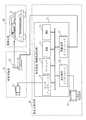
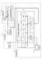
図2は、駐車場管理システムのハードウェア構成例を示す。 FIG. 2 shows a hardware configuration example of the parking lot management system.
駐車場施設20には、施設センサデバイス21と無線通信デバイス22との組が配置される。図2では、1組の施設センサデバイス21と無線通信デバイス22が示されるが、駐車場施設20には複数組の施設センサデバイス21と無線通信デバイス22が配置されているものとする。 In the
駐車場管理室30には、監視装置31と表示操作デバイス32が配置されている。
監視装置31は、センサインタフェース12、プロセッサ13、RAM(Random Access Memory)14、ROM(Read Only Memory)15、表示操作インタフェース16、無線通信インタフェース17で構成される。監視装置31は、コンピュータである。監視装置31は、一般的なパーソナルコンピュータを用いて実現してもよい。また、監視装置31は、組込機器、FPGA(Field−Programmable Gate Array)ボード等で実現されてもよい。
監視装置31は、情報処理装置に相当する。また、監視装置31により行われる動作は、情報処理方法及び情報処理プログラムに相当する。A
The
The
駐車場施設20に設置された複数の施設センサデバイス21の各々は、監視装置31と接続されている。複数の施設センサデバイス21と監視装置31は、例えばインターネットで接続される。複数の施設センサデバイス21と監視装置31がインターネットで接続されることにより、監視装置31が駐車場施設20から離れた場所にあっても、複数の施設センサデバイス21と監視装置31は通信可能である。
各施設センサデバイス21で得られた施設センサ画像データは監視装置31に送信される。監視装置31では、センサインタフェース12が各施設センサデバイス21から送信された施設センサ画像データを受信する。受信された施設センサ画像データは、RAM14に一時的に保存される。次に、プロセッサ13が、施設センサ画像データの優先度を算出する。優先度が高い施設センサ画像データは、表示操作インタフェース16を介して接続した表示操作デバイス32に優先的に表示される。
表示操作デバイス32は、例えば表示ディスプレイ付きのタッチパネルである。
管理者300が表示操作デバイス32に入力した自動運転車両41への指示は、表示操作インタフェース16で受信される。プロセッサ13が、管理者300からの指示に従って車両制御情報を生成する。生成された車両制御情報は無線通信インタフェース17から駐車場施設20に設置された無線通信デバイス22に送信される。
無線通信デバイス22は、監視装置31から送信された車両制御情報を受信し、受信した車両制御情報を配信する。Each of the plurality of
Facility sensor image data obtained by each
The
The instruction to the
The
自動運転車両41は、無線通信デバイス42を搭載している。
無線通信デバイス42は、無線通信デバイス22から配信された車両制御情報を受信する。
通常は、自動運転車両41は、自動駐車機能によって走行する。しかし、自動運転車両41は、無線通信デバイス42が車両制御情報を受信した際は、車両制御情報の指示を優先して走行停止や走行開始を行う。The
The
Normally, the
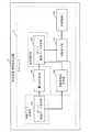
図3は、監視装置31の機能構成例を示す。 FIG. 3 shows a functional configuration example of the
監視装置31は、第1の画像データ取得部101、優先度設定部102、第1の画像データ表示部103、制御指示部104及び移動制御部105を有する。
第1の画像データ取得部101、優先度設定部102、第1の画像データ表示部103、制御指示部104及び移動制御部105は、プログラムにより実現される。第1の画像データ取得部101、優先度設定部102、第1の画像データ表示部103、制御指示部104及び移動制御部105を実現するプログラムはROM15に格納されている。当該プログラムはROM15からRAM14にロードされる。そして、当該プログラムはプロセッサ13により読み出され、プロセッサ13により実行される。
図3は、プロセッサ13が第1の画像データ取得部101、優先度設定部102、第1の画像データ表示部103、制御指示部104及び移動制御部105の機能を実現するプログラムを実行している状態を模式的に表している。The
The first image
In FIG. 3, the
第1の画像データ取得部101は、センサインタフェース12を介して、複数の無線通信デバイス22から送信された複数の施設センサ画像データを取得する。 The first image
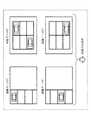
図4は、施設センサデバイス21がカメラセンサである場合の施設センサ画像データの例を示す。
画像データA、画像データB、画像データC及び画像データDは、それぞれ、異なる位置に配置された施設センサデバイス21により撮影された施設センサ画像データである。画像データA、画像データB、画像データC及び画像データDは、駐車場施設20の異なる領域の状況を表す。
また、施設センサデバイス21として、赤外線センサ又は光レーザセンサを使用することができる。赤外線センサは、温度変化を計測可能である。このため、施設センサデバイス21として赤外線センサを用いる場合は、施設センサデバイス21は、駐車場200内の歩行者を検知することができる。光レーザセンサは、投射光が物体に反射して到達するまでの時間から距離情報を算出する。レーザ光を様々な角度へ投射することで、光レーザセンサは、駐車場施設20の3次元形状を計測する。
第1の画像データ取得部101は、このように、駐車場200内の自動運転車両41の位置や外観、歩行者の有無、駐車場施設20の3次元形状等の情報を取得することができる。
第1の画像データ取得部101は、画像データ取得部に相当する。また、第1の画像データ取得部101により行われる処理は、画像データ取得処理に相当する。FIG. 4 shows an example of facility sensor image data when the
Image data A, image data B, image data C, and image data D are facility sensor image data photographed by
Further, an infrared sensor or an optical laser sensor can be used as the
In this way, the first image
The first image
優先度設定部102は、第1の画像データ取得部101により取得された複数の施設センサ画像データの各々に優先度を設定する。この優先度は、管理者300に施設センサ画像データを表示するための優先度である。
優先度が高い施設センサ画像データほど、視認性の高い表示形態で表示される。
優先度設定部102は、危険度をもとに優先度を算出する。優先度設定部102は、各施設センサ画像データに映されている状況を解析して、各施設センサ画像データに映されている領域の危険度を推定する。優先度設定部102は、例えば、車両同士の距離と混雑度、歩行者の有無、手動運転車両の有無のうちのいずれか又はこれらのうちのいずれかの組み合わせにより危険度を推定する。そして、優先度設定部102は、推定した危険度に基づき各施設センサ画像データに優先度を設定する。優先度設定部102は、危険度の高い施設センサ画像データほど高い優先度を設定する。
優先度設定部102により行われる処理は、優先度設定処理に相当する。The
The facility sensor image data with higher priority is displayed in a display form with higher visibility.
The
The processing performed by the
図5は、駐車場200の鳥瞰画像図の一例を示す。つまり、図5は、駐車場200の全体を上方から撮影した場合に得られる画像データである。図5の枠線(駐車場200の白枠)内にある車両は駐車中の車両であり、停止状態にある。図5の枠線外にある車両A、車両B及び車両Cは自動駐車のための自動走行中の車両であり、移動状態にある。
優先度設定部102は、自動走行中の車両が映されている施設センサ画像データの危険度を、停止中の車両が映されている施設センサ画像データの危険度よりも高く設定する。FIG. 5 shows an example of a bird's-eye view image of the
The
また、優先度設定部102は、他の車両との距離が近い車両が映されている施設センサ画像データほど危険度を高く設定する。
優先度設定部102は、第1の画像データ取得部101が取得した車両の位置情報を使用して、車両同士の距離を算出する。なお、優先度設定部102は、車両間の直線距離を算出するのではなく、駐車場内での移動距離(道のり)を算出する。図5の車両Aと車両Bの直線距離と、車両Aと車両Cの直線距離はほぼ等しいが、車両Aと車両Cの間には枠線(白枠)(駐車スペース)が存在するため、車両Aの位置から車両Cの位置までの移動距離は車両Aの位置から車両Bの位置までの移動距離よりも長くなる。従って、車両Aが映されている施設センサ画像データの危険度及び車両Bが映されている施設センサ画像データの危険度は、車両Cが映されている施設センサ画像データの危険度よりも高くなる。なお、優先度設定部102は、後述する鳥瞰画像図生成部106により生成された鳥瞰画像図を解析して、車両間の距離を算出する。Further, the
The
また、優先度設定部102は、車両の混雑度が高い施設センサ画像データほど危険度を高く設定する。
優先度設定部102は、鳥瞰画像図を解析して駐車場200内の一定の面積において車両が占める割合を算出して、車両の混雑度を判定する。Further, the
The
また、優先度設定部102は、歩行者が映っている施設センサ画像データほど危険度を高く設定する。つまり、優先度設定部102は、施設センサ画像データを解析して歩行者を検出する。そして、優先度設定部102は、施設センサ画像データに映っている歩行者の数が多い施設センサ画像データほど危険度を高くする。 Further, the
また、優先度設定部102は、手動運転車両が映っている施設センサ画像データの危険度を、手動運転車両が映っていない施設センサ画像データの危険度よりも高く設定する。
後述する移動制御部105によって、制御不能な車両は手動運転車両と判定される。優先度設定部102は、施設センサ画像データに映っている車両のナンバープレートに基づいて施設センサ画像データに車道運転車両が映っているか否かを判定する。The
A vehicle that cannot be controlled is determined to be a manually operated vehicle by a
また、優先度設定部102は、車道において走行を停止している自動運転車両が映っている施設センサ画像データの危険度を、走行を停止している自動運転車両が映っていない施設センサ画像データよりも危険度よりも高く設定する。
自動運転車両は、近くに車両が所在している場合は安全を考慮して走行を停止する。このため、優先度設定部102は、車道において走行を停止している自動運転車両が映っている施設センサ画像データの危険度を高く設定する。
また、優先度設定部102は、自動運転車両に自動走行時の難易度を算出させてもよい。そして、優先度設定部102は、難易度情報を第1の画像データ取得部101を介して取得し、難易度が高い車両が映っている施設センサ画像データの危険度を高くしてもよい。In addition, the
The autonomous driving vehicle stops traveling in consideration of safety when the vehicle is nearby. For this reason, the
Further, the
以上の手順にて、優先度設定部102は、複数の施設センサデバイス21で得られた施設センサ画像データの各々に優先度を算出する。 With the above procedure, the
第1の画像データ表示部103は、優先度設定部102により設定された優先度に従い、複数の施設センサ画像データを表示する際の表示形態を決定する。そして、第1の画像データ表示部103は、表示操作インタフェース16を介して、決定した表示形態で複数の施設センサ画像データを表示操作デバイス32に表示する。
第1の画像データ表示部103は、表示制御部に相当する。また、第1の画像データ表示部103により行われる処理は、表示制御処理に相当する。The first image
The first image
図6は、施設センサ画像データの表示例を示す。
図6は、表示操作デバイス32に、優先度の順に施設センサ画像データを並べて表示する例を示す。図6の例では、画面の左上の領域に最も優先度の高い施設センサ画像データが表示される。また、画面の右上の領域に2番目に優先度が高い施設センサ画像データが表示される。また、画面の左下の領域に3番目に優先度が高い施設センサ画像データが表示される。また、画面の右下の領域に最も優先度の低い施設センサ画像データが表示される。
また、監視装置31がn(n≧3)個の施設センサデバイス21により得られたn個の施設センサ画像データを受信している場合に、第1の画像データ表示部103は、優先度に基づき、m(2≦m<n)個の施設センサ画像データを選択し、m個の施設センサ画像データのみを表示操作デバイス32に表示させるようにしてもよい。FIG. 6 shows a display example of facility sensor image data.
FIG. 6 shows an example in which the facility sensor image data is arranged and displayed on the
In addition, when the
また、図6では4つの施設センサ画像データを同じサイズで表示しているが、優先度に応じて、施設センサ画像データの表示サイズを変更してもよい。
図7は、優先度に応じて施設センサ画像データの表示サイズを変化させている例を示す。
図7の例では、優先度が高い施設センサ画像データほど表示サイズが大きい。In FIG. 6, the four facility sensor image data are displayed in the same size, but the display size of the facility sensor image data may be changed according to the priority.
FIG. 7 shows an example in which the display size of the facility sensor image data is changed according to the priority.
In the example of FIG. 7, the facility sensor image data with higher priority has a larger display size.
また、第1の画像データ表示部103は、図5に例示した駐車場200の鳥瞰画像図を表示してもよい。第1の画像データ表示部103が駐車場200の鳥瞰画像図を表示する場合は、図8に示すように、図3の機能構成例に鳥瞰画像図生成部106が追加される。
鳥瞰画像図生成部106は、複数の施設センサデバイス21で得られた複数の施設センサ画像データから鳥瞰画像図を生成する。
鳥瞰画像図生成部106も、第1の画像データ取得部101、優先度設定部102、第1の画像データ表示部103、制御指示部104及び移動制御部105と同様にプログラムで実現される。
なお、図8に示す機能構成では、第1の画像データ表示部103及び鳥瞰画像図生成部106が表示制御部に相当する。The first image
The bird's-eye image
The bird's-eye image
In the functional configuration shown in FIG. 8, the first image
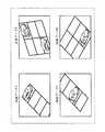
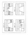
図9、図10及び図11に鳥瞰画像図生成部106による鳥瞰画像図の生成手順を示す。 9, 10, and 11 show a procedure for generating a bird's-eye image map by the bird's-eye image
図9の画像データA、画像データB、画像データC及び画像データDは、それぞれ、図4に示した画像データA、画像データB、画像データC及び画像データDと同じである。カメラセンサの設置位置と設置方向が既知であれば、鳥瞰画像図生成部106は、施設センサ画像データをアフィン変換(画像データの拡大縮小、回転及び平行移動)する。具体的には、鳥瞰画像図生成部106はアフィン変換により、画像データA、画像データB、画像データC及び画像データDを、図10に示すように、駐車場200を真上から見た画像データである画像データA’、画像データB’、画像データC’及び画像データD’に変換することができる。また、カメラセンサの設置方向が既知でない場合は、鳥瞰画像図生成部106が、駐車場200の枠線(白枠)の形状を参照して、画像変換を行ってもよい。また、カメラセンサの設置位置が既知でない場合は、鳥瞰画像図生成部106は、駐車場200の路面に印字された番号情報等を施設センサ画像データから認識し、カメラセンサの設置位置を推定してもよい。 Image data A, image data B, image data C, and image data D in FIG. 9 are the same as image data A, image data B, image data C, and image data D shown in FIG. If the installation position and the installation direction of the camera sensor are known, the bird's-eye image
次に、鳥瞰画像図生成部106は、アフィン変換により得られた画像データA’、画像データB’、画像データC’及び画像データD’を合成して、図11に示すように、駐車場200の全体の鳥瞰画像図を生成する。
鳥瞰画像図生成部106は、隣接するカメラセンサの施設センサ画像データの一部が相互に重なり合うようにして施設センサ画像データを合成する。このため、鳥瞰画像図生成部106は、カメラセンサのズーム機能を調整してもよい。より具体的には、鳥瞰画像図生成部106は、カメラセンサのズーム機能を調整して、カメラセンサの撮影領域を拡大又は縮小し、施設センサ画像データの一部が相互に重なり合うように制御する。Next, the bird's-eye view
The bird's-eye image
以上より、鳥瞰画像図生成部106は、複数台のカメラセンサの複数の施設センサ画像データを合成して駐車場200の全体の鳥瞰画像図を生成することができる。
そして、第1の画像データ表示部103は、鳥瞰画像図を、管理者300に提示することができる。As described above, the bird's-eye image
Then, the first image
また、第1の画像データ表示部103は、図12に示すように、優先度設定部102により設定された優先度が規定の条件に合致する施設センサ画像データが反映されている鳥瞰画像図の部分を強調表示するようにしてもよい。
つまり、第1の画像データ表示部103は、閾値以上の優先度が設定されている施設センサ画像データが反映されている部分を強調表示してもよい。図12では、歩行者が映っている施設センサ画像データの優先度が閾値以上であるため、鳥瞰画像図内で歩行者が映っている部分が円で囲まれて強調表示されている。同様に、図12では、車両Aと車両Bの距離が短いため、車両Aが映っている施設センサ画像データの優先度と車両Bが映っている施設センサ画像データの優先度が閾値以上であり、このため、鳥瞰画像図内で車両Aと車両Bとが映っている部分が円で囲まれて強調表示されている。
図12に示すように、第1の画像データ表示部103は優先度が高い部分を強調表示することで、管理者300が危険を認識しやすくなる。In addition, as shown in FIG. 12, the first image
That is, the first image
As shown in FIG. 12, the first image
制御指示部104は、管理者300が例えば表示操作デバイス32に入力した自動運転車両41への指示に基づき、コマンドを生成する。そして、制御指示部104は、生成したコマンドを移動制御部105に出力する。
制御指示部104が生成するコマンドは、全自動運転車両41の停止を指示する全停止コマンド、特定の自動運転車両41の停止を指示する停止コマンド及び特定の自動運転車両41の移動を指示する移動コマンドのいずれかである。The
The commands generated by the
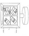
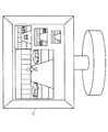
本実施の形態では、例えば図13に示す表示操作デバイス32が用いられる。図13の表示操作デバイス32は表示ディスプレイ付きタッチパネルである。
図13の表示操作デバイス32の表示画面には、鳥瞰画像図生成部106が生成した駐車場200の全体の鳥瞰画像図が表示されている。表示画面の右側には全停止ボタン、停止ボタン及び移動ボタンが表示されている。これら全停止ボタン、停止ボタン及び移動ボタンは第1の画像データ表示部103により表示される。In the present embodiment, for example, a
On the display screen of the
管理者300が駐車場200を走行している全ての自動運転車両41の走行を停止する場合は、管理者300は表示画面の全停止ボタンをタッチする。全停止ボタンのタッチにより制御指示部104に駐車場200を走行している全ての自動運転車両41の走行を停止させる旨の指示が通知される。この結果、管理者300は、全ての自動運転車両41の走行を停止させることができる。 When the
管理者300が特定の自動運転車両41の走行を停止する場合は、管理者300は、初めに表示画面の停止ボタンをタッチする。次に、管理者300は、停止させる自動運転車両41を鳥瞰画像図上でタッチする。これらの操作により、制御指示部104に特定の自動運転車両41の走行を停止させる旨の指示が通知される。この結果、管理者300は特定の自動運転車両41の走行の停止させることができる。 When the
また、管理者300が特定の自動運転車両41を特定の場所へ移動させる場合は、管理者300は、初めに表示画面の移動ボタンをタッチする。次に、管理者300は、移動させる自動運転車両41を鳥瞰画像図上でタッチし、自動運転車両41をタッチした状態で任意の移動先まで指を移動させる。指の移動軌跡が当該自動運転車両41の走行経路となる。これらの操作により、制御指示部104に特定の自動運転車両41を特定の場所に移動させる旨の指示が通知される。この結果、管理者300は特定の自動運転車両41を特定の場所に移動させることができる。
なお、指を用いた走行経路の指示は指示精度が低いため、指がタッチパネル上で駐車場200の走行路面から外れた場合には、制御指示部104が、走行経路が走行路面内にとどまるように走行経路を修正する。When the
In addition, since the instruction accuracy of the travel route using the finger is low, the
また、図14に示すように、表示操作デバイス32に全停止ボタン33が接続されていてもよい。管理者300が全停止ボタン33を押すと、制御指示部104に駐車場200を走行している全ての自動運転車両41の走行を停止させる旨の指示が通知される。この結果、管理者300は、全ての自動運転車両41の走行を停止させることができる。
なお、図14に示すように表示操作デバイス32に全停止ボタン33が接続されている場合も、特定の自動運転車両41の停止及び特定の自動運転車両41の移動は、図13に示した停止ボタン及び移動ボタンを用いて行われる。Further, as shown in FIG. 14, a
In addition, also when the all
制御指示部104は、管理者300からの指示が特定の自動運転車両41の停止指示であれば、表示操作インタフェース16を介して、当該自動運転車両41の現在位置の地理座標を表示操作デバイス32から取得する。次に、制御指示部104は、表示操作デバイス32から取得した当該自動運転車両41の現在位置の地理座標の近傍に配置されている無線通信デバイス22を特定する。そして、制御指示部104は、特定した無線通信デバイス22の識別子と停止コマンドとを移動制御部105に出力する。ROM15には、各無線通信デバイス22の識別子と各無線通信デバイス22の配置位置の地理座標とが示される無線通信デバイス座標情報が記憶されている。制御指示部104は、無線通信デバイス座標情報を用いて、自動運転車両41の現在位置の近傍に配置されている無線通信デバイス22を特定する。
また、制御指示部104は、管理者300からの指示が特定の自動運転車両41の移動指示であれば、表示操作インタフェース16を介して、当該自動運転車両41の現在位置の地理座標と、当該自動運転車両41の移動先の地理座標と、当該自動運転車両41の現在位置と移動先との間の1つ以上の中間地点の地理座標を表示操作デバイス32から取得する。次に、制御指示部104は、表示操作デバイス32から取得した当該自動運転車両41の現在位置の地理座標の近傍に配置されている無線通信デバイス22を特定する。そして、制御指示部104は、特定した無線通信デバイス22の識別子と、移動先の地理座標と、中間地点の地理座標と、移動コマンドとを移動制御部105に出力する。
また、制御指示部104は、管理者300からの指示が全自動運転車両41の停止指示であれば、駐車場200に配置されている全ての無線通信デバイス22の識別子を抽出する。そして、制御指示部104は、全ての無線通信デバイス22の識別子と、全停止コマンドとを移動制御部105に出力する。If the instruction from the
In addition, if the instruction from the
Further, if the instruction from the
移動制御部105は、制御指示部104により出力されたコマンドが含まれる車両制御情報を自動運転車両41に送信する。
具体的には、移動制御部105は、制御指示部104から停止コマンドと無線通信デバイス22の識別子が出力された場合は、停止コマンドが含まれる車両制御情報を、制御指示部104から出力された識別子に対応する無線通信デバイス22に送信する。
また、移動制御部105は、制御指示部104から移動コマンドと、無線通信デバイス22の識別子と、移動先の地理座標と、中間地点の地理座標とが出力された場合は、移動コマンドと移動先の地理座標と中間地点の地理座標とが含まれる車両制御情報を、制御指示部104から出力された識別子に対応する無線通信デバイス22に送信する。
また、移動制御部105は、全停止コマンドと全ての無線通信デバイス22の識別子が出力された場合は、全停止コマンドが含まれる車両制御情報を、全ての無線通信デバイス22に送信する。
車両制御情報を受信した無線通信デバイス22は、車両制御情報を周囲に配信する。
車両制御情報の送信先の自動運転車両41の無線通信デバイス42は、車両制御情報を配信する無線通信デバイス22の近傍に所在するため、車両制御情報を受信することができる。The
Specifically, when the stop command and the identifier of the
In addition, the
Further, when the all stop command and the identifiers of all the
The
Since the
***動作の説明***
次に、本実施の形態に係る監視装置31の動作例を説明する。
図15は、施設センサ画像データの取得から施設センサ画像データの表示までの監視装置31の手順を示すフローチャートである。*** Explanation of operation ***
Next, an operation example of the
FIG. 15 is a flowchart illustrating a procedure of the
ステップS11において、第1の画像データ取得部101が、施設センサデバイス21で得られた施設センサ画像データを取得する。 In step S <b> 11, the first image
次に、ステップS12において、優先度設定部102が、ステップS11で取得された施設センサ画像データの優先度を算出する。前述したように、優先度設定部102は、車両の混雑度、歩行者の有無、走行停止中の自動運転車両41の有無等に基づき危険度を算出し、危険度に基づき優先度を設定する。 Next, in step S12, the
次に、ステップS13では、第1の画像データ表示部103が、ステップS12で設定された優先度に従い、表示操作デバイス32に施設センサ画像データを表示する際の表示形態を決定し、決定した表示形態で表示画面を生成する。そして、第1の画像データ表示部103は、表示操作インタフェース16を介して、生成した表示画面を表示操作デバイス32に出力する。
つまり、図6のように施設センサ画像データを表示する場合は、第1の画像データ表示部103は、左上の領域に最も優先度の高い施設センサ画像データAを表示し、右上の領域に2番目に優先度が高い施設センサ画像データBを表示するというように、優先度に従った表示形態を決定する。
また、図7のように施設センサ画像データを表示する場合は、第1の画像データ表示部103は、最も優先度の高い画像データAを最も大きく表示し、2番目に優先度が高い画像データBを画像データAよりも小さいサイズで画像データAの右に表示するというように、優先度に従った表示形態を決定する。Next, in step S13, the first image
That is, when the facility sensor image data is displayed as shown in FIG. 6, the first image
Further, when the facility sensor image data is displayed as shown in FIG. 7, the first image
ステップS14では、第1の画像データ表示部103が、施設センサ画像データの表示を継続するか否かを判定する。施設センサ画像データの表示を継続する場合は、ステップS11〜S13の処理が繰り返し行われる。 In step S14, the first image
以上より、監視装置31は、駐車場施設20に設置された複数の施設センサデバイス21で得られた複数の施設センサ画像データに優先度を設定し、優先度に応じて複数の施設センサ画像データを管理者300が視認しやすい表示形態で表示する。 As described above, the
図16は、管理者300からの指示の取得から車両制御情報の送信までの監視装置31の手順を示すフローチャートである。 FIG. 16 is a flowchart illustrating a procedure of the
ステップS21では、制御指示部104が、管理者300からの指示が入力されるのを待つ。 In step S21, the
表示操作デバイス32及び表示操作インタフェース16を介して管理者300から指示が入力された場合(ステップS22でYES)に、制御指示部104は、ステップS23で、コマンドを生成する。
前述したように、管理者300からの指示が特定の自動運転車両41の停止指示であれば、制御指示部104は、停止コマンドを生成する。管理者300からの指示が特定の自動運転車両41の移動指示であれば、制御指示部104は、移動コマンドを生成する。管理者300からの指示が全自動運転車両41の停止指示であれば、制御指示部104は、全停止コマンドを生成する。
また、前述したように、制御指示部104は、管理者300からの指示が特定の自動運転車両41の停止指示であれば、表示操作インタフェース16を介して、当該自動運転車両41の現在位置の地理座標を表示操作デバイス32から取得する。次に、制御指示部104は、表示操作デバイス32から取得した当該自動運転車両41の現在位置の地理座標の近傍に配置されている無線通信デバイス22を特定する。そして、制御指示部104は、特定した無線通信デバイス22の識別子と停止コマンドとを移動制御部105に出力する。
また、制御指示部104は、管理者300からの指示が特定の自動運転車両41の移動指示であれば、表示操作インタフェース16を介して、当該自動運転車両41の現在位置の地理座標と、当該自動運転車両41の移動先の地理座標と、当該自動運転車両41の現在位置と移動先との間の1つ以上の中間地点の地理座標を表示操作デバイス32から取得する。次に、制御指示部104は、表示操作デバイス32から取得した当該自動運転車両41の現在位置の地理座標の近傍に配置されている無線通信デバイス22を特定する。そして、制御指示部104は、特定した無線通信デバイス22の識別子と、移動先の地理座標と、中間地点の地理座標と、移動コマンドとを移動制御部105に出力する。
また、制御指示部104は、管理者300からの指示が全自動運転車両41の停止指示であれば、駐車場200に配置されている全ての無線通信デバイス22の識別子を抽出する。そして、制御指示部104は、全ての無線通信デバイス22の識別子と、全停止コマンドとを移動制御部105に出力する。When an instruction is input from the
As described above, if the instruction from the
Further, as described above, if the instruction from the
In addition, if the instruction from the
Further, if the instruction from the
次に、ステップS24において、移動制御部105が、制御指示部104により出力されたコマンドが含まれる車両制御情報を無線通信デバイス22に送信する。
具体的には、移動制御部105は、制御指示部104から停止コマンドと無線通信デバイス22の識別子が出力された場合は、停止コマンドが含まれる車両制御情報を、制御指示部104から出力された識別子に対応する無線通信デバイス22に送信する。
また、移動制御部105は、制御指示部104から移動コマンドと、無線通信デバイス22の識別子と、移動先の地理座標と、中間地点の地理座標とが出力された場合は、移動コマンドと移動先の地理座標と中間地点の地理座標とが含まれる車両制御情報を、制御指示部104から出力された識別子に対応する無線通信デバイス22に送信する。
また、移動制御部105は、全停止コマンドと全ての無線通信デバイス22の識別子が出力された場合は、全停止コマンドが含まれる車両制御情報を、全ての無線通信デバイス22に送信する。Next, in step S <b> 24, the
Specifically, when the stop command and the identifier of the
In addition, the
Further, when the all stop command and the identifiers of all the
ステップS25では、制御指示部104が、自動運転車両41の制御を継続するか否かを判定する。自動運転車両41の制御を継続する場合は、ステップS21〜S24の処理が繰り返し行われる。 In step S25, the
以上のように、監視装置31は、管理者300の指示に従って、自動運転車両41の走行制御を行う。 As described above, the
***実施の形態の効果の説明***
本実施の形態では、監視装置31は、駐車場施設20に設置された複数の施設センサデバイス21で得られた複数の施設センサ画像データに優先度を設定し、優先度に応じて複数の施設センサ画像データを管理者300が視認しやすい表示形態で表示する。このため、本実施の形態によれば、管理者300は、優先度の高い施設センサ画像データに着目して自動運転車両41の走行状況を監視することができる。従って、本実施の形態では、1人の管理者300が複数の自動運転車両41の運転支援を行うことができ、駐車場施設20における自動運転車両による事故を有効に防止することができる。*** Explanation of the effect of the embodiment ***
In the present embodiment, the
実施の形態2.
実施の形態2に係る監視装置31は、駐車場施設20に設置した施設センサデバイス21だけでなく、自動運転車両41に搭載したセンサデバイスで得られた画像データを使用する。このようにすることで、管理者300がより効率的に自動運転車両41の運転支援を行うことができる。
本実施の形態では、主に実施の形態1との差異を説明する。
なお、以下で説明していない事項は、実施の形態1と同様である。Embodiment 2. FIG.
The
In the present embodiment, differences from the first embodiment will be mainly described.
Note that matters not described below are the same as those in the first embodiment.
***構成の説明***
本実施の形態でも、駐車場管理システムの全体構成は図1に示す通りである。
図17は、本実施の形態に係る駐車場管理システムのハードウェア構成例を示す。*** Explanation of configuration ***
Also in this embodiment, the overall configuration of the parking lot management system is as shown in FIG.
FIG. 17 shows a hardware configuration example of the parking lot management system according to the present embodiment.
図17では、図2のハードウェア構成と比較して、自動運転車両41に車両センサデバイス43が搭載されている。車両センサデバイス43は、カメラセンサ、赤外線センサ、光レーザセンサ、ミリ波レーダセンサ、超音波センサ等である。
車両センサデバイス43で得られた画像データ(以下、車両センサ画像データという)は、無線通信デバイス42により、無線通信デバイス22に送信される。
無線通信デバイス22は、車両センサ画像データを監視装置31に送信する。
監視装置31では、センサインタフェース12が車両センサ画像データを受信する。
図17において、車両センサデバイス43以外の構成要素は、図2に示したものと同じであるため、説明を省略する。In FIG. 17, the vehicle sensor device 43 is mounted on the
Image data (hereinafter referred to as vehicle sensor image data) obtained by the vehicle sensor device 43 is transmitted to the
The
In the
In FIG. 17, the components other than the vehicle sensor device 43 are the same as those shown in FIG.
図18は、本実施の形態に係る監視装置31の機能構成例を示す。 FIG. 18 shows a functional configuration example of the
図18では、図3の機能構成例と比較して、第2の画像データ取得部201と第2の画像データ表示部202が追加されている。
第2の画像データ取得部201及び第2の画像データ表示部202は、第1の画像データ取得部101、優先度設定部102、第1の画像データ表示部103、制御指示部104及び移動制御部105と同様にプログラムにより実現される。
第2の画像データ取得部201は、センサインタフェース12を介して、複数の車両センサデバイス43から送信された複数の車両センサ画像データを取得する。
図19は、車両センサデバイス43がカメラセンサである場合の車両センサ画像データの例を示す。画像データP、画像データQ、画像データR及び画像データSは、異なる自動運転車両41に配置された車両センサデバイス43により撮影された撮影画像である。
画像データPでは、画像データPを撮影した車両センサデバイス43を搭載した自動運転車両41の左右に駐車車両が存在している。画像データQでは、画像データPを撮影した車両センサデバイス43を搭載した自動運転車両41の前方に歩行者が歩行している。画像データRでは、画像データRを撮影した車両センサデバイス43を搭載した自動運転車両41の前方に走行中の他車両が存在している。画像データSでは、画像データSを撮影した車両センサデバイス43を搭載した自動運転車両41の周囲に他車両や歩行者が存在しない。
また、車両センサデバイス43として、赤外線センサ、光レーザセンサ、ミリ波レーダセンサ、超音波センサ等を使用することができる。赤外線センサ、光レーザセンサは実施の形態1で説明した通りであり、歩行者の有無や駐車場施設20の3次元形状を計測することができる。ミリ波レーダセンサは、ミリ波帯域の電波を使用することで、霧の中や降雨又は降雪時であっても車両や歩行者などの障害物を検出することができる。超音波センサは、他センサと比べて安価であり、近距離にある障害物を検出することができる。第2の画像データ取得部201は、このように、自動運転車両41の周辺にある障害物(歩行者又は他車両)、自動運転車両41の周辺の駐車場200内の状況、自動運転車両41の周辺の3次元形状等を取得することができる。
なお、本実施の形態では、第1の画像データ取得部101及び第2の画像データ取得部201が、画像データ取得部に相当する。また、第1の画像データ取得部101及び第2の画像データ取得部201により行われる処理が、画像データ取得処理に相当する。In FIG. 18, a second image
The second image
The second image
FIG. 19 shows an example of vehicle sensor image data when the vehicle sensor device 43 is a camera sensor. The image data P, the image data Q, the image data R, and the image data S are captured images that are captured by the vehicle sensor device 43 disposed in different
In the image data P, parked vehicles exist on the left and right of the
As the vehicle sensor device 43, an infrared sensor, an optical laser sensor, a millimeter wave radar sensor, an ultrasonic sensor, or the like can be used. The infrared sensor and the optical laser sensor are as described in the first embodiment, and can measure the presence or absence of a pedestrian and the three-dimensional shape of the
In the present embodiment, the first image
本実施の形態に係る優先度設定部102は、第2の画像データ取得部201により取得された複数の車両センサ画像データの各々に優先度を設定する。この優先度は、管理者300に車両センサ画像データを表示するための優先度である。優先度が高い車両センサ画像データほど、視認性の高い表示形態で表示される。優先度設定部102は、実施の形態1と同様に、危険度をもとに優先度を算出する。
図19の画像データP、画像データQ、画像データR、画像データSの例では、優先度設定部102は、自動運転車両41の前方に歩行者が存在する画像データQの危険度を最も高く設定する。優先度設定部102は、次に自動運転車両41の前方に走行中の他車両が存在する画像データRの危険度を2番目に高く設定する。優先度設定部102は、自動運転車両41の左右に駐車車両が存在する画像データPの危険度を3番目に高く設定する。そして、優先度設定部102は、自動運転車両41の周辺に歩行者及び車両が存在しない画像データSの危険度を最も低く設定する。
この結果、図19の画像データの優先度は、画像データQ→画像データR→画像データP→画像データSの順に下がっていく。
また、優先度設定部102は、実施の形態1と同様に、優先度設定部102は、車道において走行を停止している自動運転車両の車両センサ画像データの危険度を高く設定してもよい。The
In the example of the image data P, image data Q, image data R, and image data S in FIG. 19, the
As a result, the priority of the image data in FIG. 19 decreases in the order of image data Q → image data R → image data P → image data S.
In addition, the
また、優先度設定部102は、複数の施設センサ画像データと複数の車両センサ画像データとを解析して、各車両センサ画像データに映されている領域の危険度を推定し、推定した危険度に基づき各車両センサ画像データに優先度を設定してもよい。
また、優先度設定部102は、複数の施設センサ画像データと複数の車両センサ画像データとを解析して、各施設センサ画像データに映されている領域の危険度を推定し、推定した危険度に基づき各施設センサ画像データに優先度を設定してもよい。
優先度設定部102は、自動運転車両41の周囲にある障害物(他車両及び歩行者)の有無、障害物の位置は、車両センサ画像データを用いても、施設センサ画像データを用いても検知可能である。従って、優先度設定部102は、車両センサ画像データと施設センサ画像データの両方を参照して、危険度を推定し、優先度を設定してもよい。
一方で、車両センサ画像データと施設センサ画像データに同一の障害物が映されていても、車両センサ画像データを用いた障害物の認識結果と施設センサ画像データを用いた障害物の認識結果とが異なる場合がある。図20に示す駐車場200の鳥瞰画像図を用いて、認識結果の違いについて説明する。
図20の車両Bに搭載した車両センサデバイス43と、駐車場施設20に設置されている施設センサデバイス21は同一の障害物である歩行者Aを撮影する。
しかしながら、車両センサデバイス43と施設センサデバイス21は撮影方向が異なるため、図21のように撮影画像も異なる。従って、画像データPの解析及び画像データAの解析のいずれかで誤認識が生じる可能性がある。図21の画像データPにおける歩行者の画像範囲は、画像データAにおける歩行者の画像範囲よりも小さい。小さい画像範囲の対象物を画像認識するのは一般的に困難である。このため、施設センサデバイス21では歩行者を正しく検知できるが、車両Bの車両センサデバイス43では歩行者を検知できない可能性がある。この場合に、優先度設定部102は、画像データPと画像データAとの両者を解析することで、歩行者が歩行していることを正しく認識することができ、正しく危険度を推定することができる。自動運転車両41が走行経路上の障害物を未検知である場合は、危険性が非常に高い。従って、車両センサ画像データに対する解析結果と施設センサ画像データに対す解析結果とが異なる場合には、優先度設定部102は、当該車両センサ画像データの優先度を高くしてもよい。In addition, the
The
The
On the other hand, even if the same obstacle is reflected in the vehicle sensor image data and the facility sensor image data, the obstacle recognition result using the vehicle sensor image data and the obstacle recognition result using the facility sensor image data May be different. Differences in recognition results will be described using the bird's-eye view image of the
The vehicle sensor device 43 mounted on the vehicle B in FIG. 20 and the
However, since the vehicle sensor device 43 and the
以上より、優先度設定部102は、複数台の自動運転車両41に搭載された車両センサデバイス43により得られた車両センサ画像データと、駐車場施設20に設置された複数の施設センサデバイス21により得られた施設センサ画像データとを参照して、画像データの優先度を算出することができる。 As described above, the
第2の画像データ表示部202は、優先度設定部102により設定された優先度に従い、複数の車両センサ画像データを表示する際の表示形態を決定する。そして、第2の画像データ表示部202は、表示操作インタフェース16を介して、決定した表示形態で複数の車両センサ画像データを表示操作デバイス32に表示する。
本実施の形態では、第1の画像データ表示部103及び第2の画像データ表示部202が、表示制御部に相当する。また、第1の画像データ表示部103及び第2の画像データ表示部202により行われる処理が、表示制御処理に相当する。The second image
In the present embodiment, the first image
図22は、車両センサ画像データの表示例を示す。
図22では、表示操作デバイス32に、優先度の順に車両センサ画像データを並べて表示する例を示す。図22の例では、画面の左上の領域に最も優先度の高い車両センサ画像データが表示される。右上の領域に2番目に優先度が高い車両センサ画像データが表示される。左下の領域に3番目に優先度が高い車両センサ画像データが表示される。右下の領域には最も優先度の低い車両センサ画像データが表示される。
また、監視装置31がn(n≧3)個の車両センサデバイス43により得られたn個の車両センサ画像データを受信している場合に、第2の画像データ表示部202は、優先度に基づき、m(2≦m<n)個の車両センサ画像データを選択し、m個の車両センサ画像データのみを表示操作デバイス32に表示させるようにしてもよい。FIG. 22 shows a display example of vehicle sensor image data.
FIG. 22 shows an example in which the vehicle sensor image data is arranged and displayed on the
In addition, when the
また、図22では4つの車両センサ画像データを同じサイズで表示しているが、優先度に応じて、車両センサ画像データの表示サイズを変更してもよい。
図23は、優先度に応じて車両センサ画像データの表示サイズを変化させている例を示す。
図23の例では、優先度が高い車両センサ画像データほど表示サイズが大きい。In FIG. 22, the four vehicle sensor image data are displayed in the same size, but the display size of the vehicle sensor image data may be changed according to the priority.
FIG. 23 shows an example in which the display size of the vehicle sensor image data is changed according to the priority.
In the example of FIG. 23, the vehicle sensor image data with higher priority has a larger display size.
また、第2の画像データ表示部202は、第1の画像データ表示部103又は図8に示す鳥瞰画像図生成部106が生成する表示画面と連動する表示画面を生成してもよい。
図24は、鳥瞰画像図生成部106が生成する鳥瞰画像図と連動させて、第2の画像データ表示部202が車両センサ画像データを表示する例を示す。
図24では、テーブル型表示操作デバイス321に駐車場200の鳥瞰画像図が表示され、複数台の表示操作デバイス322に複数の車両センサ画像データが表示されている。
なお、第1の画像データ表示部103は、鳥瞰画像図に車両センサ画像データに挿入してもよい。
また、鳥瞰画像図では、実施の形態1と同様に優先度が高い部分が強調表示される。また、第2の画像データ表示部202は、鳥瞰画像図で強調表示された部分に対応する車両センサ画像データを表示操作デバイス322に表示してもよい。Further, the second image
FIG. 24 shows an example in which the second image
In FIG. 24, a bird's-eye view image of the
In addition, you may insert the 1st image data display
In the bird's-eye view image diagram, as in the first embodiment, the high priority portion is highlighted. Further, the second image
以上より、監視装置31は、危険度の高い自動運転車両41の車両センサ画像データを表示操作デバイス32に優先的に表示する。このため、管理者300は、優先度の高い車両センサ画像データに着目して自動運転車両41の走行状況を監視することができる。
***動作の説明***
次に、本実施の形態に係る監視装置31の動作例を説明する。
図25は、施設センサ画像データの取得から施設センサ画像データの表示までの監視装置31の手順を示すフローチャートである。As described above, the
*** Explanation of operation ***
Next, an operation example of the
FIG. 25 is a flowchart showing the procedure of the
ステップS31において、第2の画像データ取得部201が、車両センサデバイス43で得られた車両センサ画像データを取得する。 In step S <b> 31, the second image
次に、ステップS32において、優先度設定部102が、ステップS31で取得された車両センサ画像データの優先度を算出する。前述したように、優先度設定部102は、車両の混雑度、歩行者の有無、走行停止中の自動運転車両41の有無等に基づき危険度を算出し、危険度に基づき優先度を設定する。 Next, in step S32, the
次に、ステップS33では、第2の画像データ表示部202が、ステップS32で設定された優先度に従い、表示操作デバイス32へ表示する表示形態を決定し、決定した表示形態で表示画面を生成する。そして、第2の画像データ表示部202は、表示操作インタフェース16を介して、生成した表示画面を表示操作デバイス32に出力する。
つまり、図22のように車両センサ画像データを表示する場合は、第2の画像データ表示部202は、左上の領域に最も優先度の高い画像データQを表示し、右上の領域に2番目に優先度が高い画像データRを表示するというように、優先度に従った表示形態を決定する。
また、図23のように車両センサ画像データを表示する場合は、第2の画像データ表示部202は、最も優先度の高い画像データQを最も大きく表示し、2番目に優先度が高い画像データRを画像データQよりも小さいサイズで画像データRの右に表示するというように、優先度に従った表示形態を決定する。Next, in step S33, the second image
That is, when the vehicle sensor image data is displayed as shown in FIG. 22, the second image
Further, when the vehicle sensor image data is displayed as shown in FIG. 23, the second image
ステップS34では、第2の画像データ表示部202が、車両センサ画像データの表示を継続するか否かを判定する。車両センサ画像データの表示を継続する場合は、ステップS31〜S33の処理が繰り返し行われる。 In step S34, the second image
以上より、監視装置31は、複数の自動運転車両41に搭載された複数の車両センサデバイス43で得られた複数の車両センサ画像データに優先度を設定し、優先度に応じて複数の車両センサ画像データを管理者300が視認しやすい表示形態で表示する。 As described above, the
***実施の形態の効果の説明***
本実施の形態によれば、管理者300は、優先度の高い車両センサ画像データに着目して自動運転車両41の走行状況を監視することができる。従って、本実施の形態では、1人の管理者300が複数の自動運転車両41の運転支援を行うことができ、駐車場施設20における自動運転車両による事故を有効に防止することができる。*** Explanation of the effect of the embodiment ***
According to the present embodiment, the
以上、本発明の実施の形態について説明したが、これら2つの実施の形態を組み合わせて実施しても構わない。
あるいは、これら2つの実施の形態のうち、1つを部分的に実施しても構わない。
あるいは、これら2つの実施の形態を部分的に組み合わせて実施しても構わない。
なお、本発明は、これらの実施の形態に限定されるものではなく、必要に応じて種々の変更が可能である。Although the embodiments of the present invention have been described above, these two embodiments may be combined and implemented.
Alternatively, one of these two embodiments may be partially implemented.
Alternatively, these two embodiments may be partially combined.
In addition, this invention is not limited to these embodiment, A various change is possible as needed.
また、以上では、駐車場施設20における自動走行車両の管理を説明したが、本実施の形態に係る監視装置31を、倉庫、工場等の施設における自動走行車両の管理に適用可能である。 Moreover, although the management of the automatic traveling vehicle in the
***ハードウェア構成の説明***
最後に、監視装置31のハードウェア構成の補足説明を行う。
プロセッサ13は、プロセッシングを行うIC(Integrated Circuit)である。
プロセッサ13は、CPU(Central Processing Unit)、DSP(Digital Signal Processor)等である。
ROM15には、OS(Operating System)も記憶されている。
そして、OSの少なくとも一部がRAM14にロードされ、また、プロセッサ13により読み出される。プロセッサ13は、少なくとも一部のOSを実行する。
プロセッサ13はOSの少なくとも一部を実行しながら、第1の画像データ取得部101、優先度設定部102、第1の画像データ表示部103、制御指示部104、移動制御部105、鳥瞰画像図生成部106、第2の画像データ取得部201及び第2の画像データ表示部202の機能を実現するプログラムを実行する。
プロセッサ13がOSを実行することで、タスク管理、メモリ管理、ファイル管理、通信制御等が行われる。
また、監視装置31は、プロセッサ13を代替する複数のプロセッサを備えていてもよい。これら複数のプロセッサは、第1の画像データ取得部101、優先度設定部102、第1の画像データ表示部103、制御指示部104、移動制御部105、鳥瞰画像図生成部106、第2の画像データ取得部201及び第2の画像データ表示部202の機能を実現するプログラムの実行を分担する。それぞれのプロセッサは、プロセッサ13と同じように、プロセッシングを行うICである。
また、第1の画像データ取得部101、優先度設定部102、第1の画像データ表示部103、制御指示部104、移動制御部105、鳥瞰画像図生成部106、第2の画像データ取得部201及び第2の画像データ表示部202の処理の結果を示す情報、データ、信号値及び変数値の少なくともいずれかが、RAM14、プロセッサ13内のレジスタ及びキャッシュメモリの少なくともいずれかに記憶される。
また、第1の画像データ取得部101、優先度設定部102、第1の画像データ表示部103、制御指示部104、移動制御部105、鳥瞰画像図生成部106、第2の画像データ取得部201及び第2の画像データ表示部202の機能を実現するプログラムは、磁気ディスク、フレキシブルディスク、光ディスク、コンパクトディスク、ブルーレイ(登録商標)ディスク、DVD等の可搬記憶媒体に記憶されてもよい。*** Explanation of hardware configuration ***
Finally, a supplementary explanation of the hardware configuration of the
The
The
The
Then, at least a part of the OS is loaded into the
While executing at least a part of the OS, the
When the
The
Also, the first image
Also, the first image
また、第1の画像データ取得部101、優先度設定部102、第1の画像データ表示部103、制御指示部104、移動制御部105、鳥瞰画像図生成部106、第2の画像データ取得部201及び第2の画像データ表示部202の「部」を、「回路」又は「工程」又は「手順」又は「処理」に読み替えてもよい。
また、監視装置31は、ロジックIC(Integrated Circuit)、GA(Gate Array)、ASIC(Application Specific Integrated Circuit)、FPGAといった電子回路により実現されてもよい。
この場合は、第1の画像データ取得部101、優先度設定部102、第1の画像データ表示部103、制御指示部104、移動制御部105、鳥瞰画像図生成部106、第2の画像データ取得部201及び第2の画像データ表示部202は、それぞれ電子回路の一部として実現される。
なお、プロセッサ及び上記の電子回路を総称してプロセッシングサーキットリーともいう。Also, the first image
The
In this case, the first image
The processor and the electronic circuit are also collectively referred to as a processing circuit.
12 センサインタフェース、13 プロセッサ、14 RAM、15 ROM、16 表示操作インタフェース、17 無線通信インタフェース、20 駐車場施設、21 施設センサデバイス、22 無線通信デバイス、30 駐車場管理室、31 監視装置、32 表示操作デバイス、33 全停止ボタン、40 乗車位置、41 自動運転車両、42 無線通信デバイス、43 車両センサデバイス、101 第1の画像データ取得部、102 優先度設定部、103 第1の画像データ表示部、104 制御指示部、105 移動制御部、106 鳥瞰画像図生成部、200 駐車場、201 第2の画像データ取得部、202 第2の画像データ表示部、300 管理者、400 運転手。 12 sensor interface, 13 processor, 14 RAM, 15 ROM, 16 display operation interface, 17 wireless communication interface, 20 parking facility, 21 facility sensor device, 22 wireless communication device, 30 parking management room, 31 monitoring device, 32 display Operation device, 33 all stop button, 40 boarding position, 41 autonomous driving vehicle, 42 wireless communication device, 43 vehicle sensor device, 101 first image data acquisition unit, 102 priority setting unit, 103 first image data display unit , 104 control instruction unit, 105 movement control unit, 106 bird's-eye view image generation unit, 200 parking lot, 201 second image data acquisition unit, 202 second image data display unit, 300 administrator, 400 driver.
Claims (15)
Translated fromJapanese前記複数の画像データの各々に映されている状況を解析して、各画像データに優先度を設定する優先度設定部と、
前記複数の画像データを合成して鳥瞰画像図を生成し、前記優先度設定部により設定された優先度が規定の条件に合致する画像データが反映されている前記鳥瞰画像図の部分を強調表示する表示制御部とを有する情報処理装置。An image data acquisition unit for acquiring a plurality of image data in which different areas in a facility where an autonomous driving vehicle automatically travels are reflected;
A priority setting unit that analyzes a situation reflected in each of the plurality of image data and sets a priority for each image data;
A bird's-eye view image map is generated by combining the plurality of image data, and a portion of the bird's-eye view image image that reflects image data whose priority set by the priority setting unit matches a prescribed condition is highlighted. An information processing apparatus havinga display control unit.
各画像データに映されている状況を解析して、各画像データに映されている領域の危険度を推定し、推定した危険度に基づき各画像データに優先度を設定する請求項1に記載の情報処理装置。The priority setting unit
The situation reflected in each image data is analyzed, the risk level of the area reflected in each image data is estimated, and priority is set for each image data based on the estimated risk level. Information processing device.
1つ以上の自動運転車両が自動走行し、1人以上の歩行者が歩行する施設内の異なる領域が映された複数の画像データを取得し、
前記優先度設定部は、
各画像データに映されている状況として、自動運転車両の状況及び歩行者の状況を解析して、各画像データに映されている領域の危険度を推定する請求項2に記載の情報処理装置。The image data acquisition unit
One or more self-driving vehicles automatically travel and obtain a plurality of image data showing different areas in a facility where one or more pedestrians walk;
The priority setting unit
The information processing apparatus according to claim 2, wherein as the situation reflected in each image data, the situation of an autonomous driving vehicle and the situation of a pedestrian are analyzed to estimate a risk level of an area reflected in each image data. .
前記施設に所在する複数の自動走行車両に設置されている複数のセンサデバイスで生成された複数の画像データを取得する請求項1に記載の情報処理装置。The image data acquisition unit
The information processing apparatus according to claim 1, wherein a plurality of image data generated by a plurality of sensor devices installed in a plurality of automatic traveling vehicles located in the facility are acquired.
前記複数の施設センサ画像データと前記複数の車両センサ画像データとを解析して、各施設センサ画像データに映されている領域の危険度を推定し、推定した危険度に基づき各施設センサ画像データに優先度を設定する優先度設定部と、
前記優先度設定部により設定された優先度に従い、前記複数の施設センサ画像データを表示する際の表示形態を決定する表示制御部とを有する情報処理装置。Aplurality of facility sensor image data ,which is a plurality of image datain which different regions in the facility are imaged, aregenerated by a plurality of sensor devices installed in afacility where the autonomous driving vehicle automatically travels, and the facility An image data acquisition unitthat acquires a plurality of vehicle sensor image data that is a plurality of image data generated by a plurality of sensor devices installed in a plurality of automatic traveling vehicles located in
Analyzing the plurality of facility sensor image data and the plurality of vehicle sensor image data to estimate a risk level of an area shown in each facility sensor image data, andeach facility sensor image databased on the estimated risk level A priority setting unit for setting the priority to
An information processing apparatus comprising: a display control unit that determines a display form when displaying the plurality offacility sensor image data according to the priority set by the priority setting unit.
前記複数の施設センサ画像データと前記複数の車両センサ画像データとを解析して、各車両センサ画像データに映されている領域の危険度を推定し、推定した危険度に基づき各車両センサ画像データに優先度を設定する優先度設定部と、
前記優先度設定部により設定された優先度に従い、前記複数の車両センサ画像データを表示する際の表示形態を決定する表示制御部とを有する情報処理装置。Aplurality of facility sensor image data ,which is a plurality of image datain which different regions in the facility are imaged, aregenerated by a plurality of sensor devices installed in afacility where the autonomous driving vehicle automatically travels, and the facility An image data acquisition unitthat acquires a plurality of vehicle sensor image data that is a plurality of image data generated by a plurality of sensor devices installed in a plurality of automatic traveling vehicles located in
Analyzing the plurality of facility sensor image data and the plurality of vehicle sensor image data to estimate a risk level of an area shown in each vehicle sensor image data, andeach vehicle sensor image databased on the estimated risk level A priority setting unit for setting the priority to
An information processing apparatus comprising: a display control unit that determines a display mode when displaying the plurality ofvehicle sensor image data according to the priority set by the priority setting unit.
前記自動運転車両の走行停止を指示する制御指示部を有する請求項1、5又は6に記載の情報処理装置。The information processing apparatus further includes:
The information processing apparatus according to claim 1, further comprising a control instruction unit that instructs to stop traveling of the autonomous driving vehicle.
走行経路を指定するとともに、前記走行経路に沿った前記自動運転車両の走行を指示する制御指示部を有する請求項1、5又は6に記載の情報処理装置。The information processing apparatus further includes:
The information processing apparatus according to claim 1, further comprising a control instruction unit that designates a travel route and instructs the travel of the autonomous driving vehicle along the travel route.
前記施設に複数の自動運転車両が所在する場合に、前記複数の自動運転車両の走行停止を指示する制御指示部を有する請求項1、5又は6に記載の情報処理装置。The information processing apparatus further includes:
The information processing apparatus according to claim 1, further comprising: a control instruction unit that instructs to stop traveling of the plurality of autonomous driving vehicles when the facility has a plurality of autonomous driving vehicles.
前記コンピュータが、前記複数の画像データの各々に映されている状況を解析して、各画像データに優先度を設定し、
前記コンピュータが、前記複数の画像データを合成して鳥瞰画像図を生成し、設定された優先度が規定の条件に合致する画像データが反映されている前記鳥瞰画像図の部分を強調表示する情報処理方法。A computer acquires a plurality of image data showing different areas in a facility where an autonomous driving vehicle automatically travels,
The computer analyzes the situation reflected in each of the plurality of image data, sets a priority for each image data,
Informationthat the computergenerates a bird's-eye image diagram by combining the plurality of image data, and highlights a portion of the bird's-eye image diagram in which image data whose set priority matches a specified condition is reflected Processing method.
前記コンピュータが、前記複数の施設センサ画像データと前記複数の車両センサ画像データとを解析して、各施設センサ画像データに映されている領域の危険度を推定し、推定した危険度に基づき各施設センサ画像データに優先度を設定し、
前記コンピュータが、設定された優先度に従い、前記複数の施設センサ画像データを表示する際の表示形態を決定する情報処理方法。Computer, automatically driven vehicleis generated by the plurality of sensor devices installed in the facility for automaticallyrunning theplurality ofacquiredproperty sensor image data different regionsis a plurality of image data imaged with the facilityObtaining a plurality of vehicle sensor image data that is a plurality of image data generated by a plurality of sensor devices installed in a plurality of autonomous vehicles located in the facility;
The computeranalyzes the plurality of facility sensor image data and the plurality of vehicle sensor image data, estimates a risk level of an area shown in each facility sensor image data, and determines each risk based on the estimated risk level. Set priority tofacility sensor image data,
An information processing method for determining a display form when the computer displays the plurality offacility sensor image data according to a set priority.
前記コンピュータが、前記複数の施設センサ画像データと前記複数の車両センサ画像データとを解析して、各車両センサ画像データに映されている領域の危険度を推定し、推定した危険度に基づき各車両センサ画像データに優先度を設定し、
前記コンピュータが、設定された優先度に従い、前記複数の車両センサ画像データを表示する際の表示形態を決定する情報処理方法。Computer, automatically driven vehicleis generated in a plurality of sensor devices installed in the facility for automaticallyrunning theplurality ofacquiredproperty sensor image data different regionsis a plurality of image data imaged with the facilityObtaining a plurality of vehicle sensor image data that is a plurality of image data generated by a plurality of sensor devices installed in a plurality of autonomous vehicles located in the facility;
The computeranalyzes the plurality of facility sensor image data and the plurality of vehicle sensor image data, estimates a risk level of an area shown in each vehicle sensor image data, and determines each risk based on the estimated risk level. Set priority tovehicle sensor image data,
An information processing method for determining a display form when the computer displays the plurality ofvehicle sensor image data according to a set priority.
前記複数の画像データの各々に映されている状況を解析して、各画像データに優先度を設定する優先度設定処理と、
前記複数の画像データを合成して鳥瞰画像図を生成し、前記優先度設定処理により設定された優先度が規定の条件に合致する画像データが反映されている前記鳥瞰画像図の部分を強調表示する表示制御処理とをコンピュータに実行させる情報処理プログラム。An image data acquisition process for acquiring a plurality of image data in which different areas in a facility where an autonomous driving vehicle automatically travels are reflected;
Analyzing the situation shown in each of the plurality of image data, a priority setting process for setting a priority for each image data,
The bird's-eye view image map is generated by combining the plurality of image data, and the bird's-eye view image portion in which the image data in which the priority set by the priority setting process matches a specified condition is highlighted. An information processing program for causing a computer to execute display control processing.
前記複数の施設センサ画像データと前記複数の車両センサ画像データとを解析して、各施設センサ画像データに映されている領域の危険度を推定し、推定した危険度に基づき各施設センサ画像データに優先度を設定する優先度設定処理と、
前記優先度設定処理により設定された優先度に従い、前記複数の施設センサ画像データを表示する際の表示形態を決定する表示制御処理とをコンピュータに実行させる情報処理プログラム。Aplurality of facility sensor image data ,which is a plurality of image datain which different regions in the facility are imaged, aregenerated by a plurality of sensor devices installed in afacility where the autonomous driving vehicle automatically travels, and the facility Image data acquisition processingfor acquiring a plurality of vehicle sensor image data, which are a plurality of image data generated by a plurality of sensor devices installed in a plurality of automatic traveling vehicles located in
Analyzing the plurality of facility sensor image data and the plurality of vehicle sensor image data to estimate a risk level of an area shown in each facility sensor image data, andeach facility sensor image databased on the estimated risk level Priority setting processing for setting the priority to
An information processing program for causing a computer to execute a display control process for determining a display form when displaying the plurality offacility sensor image data according to the priority set by the priority setting process.
前記複数の施設センサ画像データと前記複数の車両センサ画像データとを解析して、各車両センサ画像データに映されている領域の危険度を推定し、推定した危険度に基づき各車両センサ画像データに優先度を設定する優先度設定処理と、
前記優先度設定処理により設定された優先度に従い、前記複数の車両センサ画像データを表示する際の表示形態を決定する表示制御処理とをコンピュータに実行させる情報処理プログラム。Aplurality of facility sensor image data ,which is a plurality of image datain which different regions in the facility are imaged, aregenerated by a plurality of sensor devices installed in afacility where the autonomous driving vehicle automatically travels, and the facility Image data acquisition processingfor acquiring a plurality of vehicle sensor image data, which are a plurality of image data generated by a plurality of sensor devices installed in a plurality of automatic traveling vehicles located in
Analyzing the plurality of facility sensor image data and the plurality of vehicle sensor image data to estimate a risk level of an area shown in each vehicle sensor image data, andeach vehicle sensor image databased on the estimated risk level Priority setting processing for setting the priority to
An information processing program for causing a computer to execute a display control process for determining a display mode when displaying the plurality ofvehicle sensor image data according to the priority set by the priority setting process.
Applications Claiming Priority (1)
| Application Number | Priority Date | Filing Date | Title |
|---|---|---|---|
| PCT/JP2017/010502WO2018167891A1 (en) | 2017-03-15 | 2017-03-15 | Information processing device, information processing method, and information processing program |
Publications (2)
| Publication Number | Publication Date |
|---|---|
| JP6227211B1true JP6227211B1 (en) | 2017-11-08 |
| JPWO2018167891A1 JPWO2018167891A1 (en) | 2019-03-28 |
Family
ID=60265754
Family Applications (1)
| Application Number | Title | Priority Date | Filing Date |
|---|---|---|---|
| JP2017539046AActiveJP6227211B1 (en) | 2017-03-15 | 2017-03-15 | Information processing apparatus, information processing method, and information processing program |
Country Status (5)
| Country | Link |
|---|---|
| US (1) | US11366477B2 (en) |
| JP (1) | JP6227211B1 (en) |
| CN (1) | CN110419211B (en) |
| DE (1) | DE112017007050B4 (en) |
| WO (1) | WO2018167891A1 (en) |
Cited By (4)
| Publication number | Priority date | Publication date | Assignee | Title |
|---|---|---|---|---|
| JP2019128687A (en)* | 2018-01-22 | 2019-08-01 | トヨタホーム株式会社 | Monitoring system |
| JP2020061120A (en)* | 2018-10-05 | 2020-04-16 | パナソニック インテレクチュアル プロパティ コーポレーション オブ アメリカPanasonic Intellectual Property Corporation of America | Information processing method and information processing system |
| JP2022034034A (en)* | 2020-12-25 | 2022-03-02 | アポロ インテリジェント コネクティビティ (ベイジン) テクノロジー カンパニー リミテッド | Method for detecting obstacle, electronic device, roadside device and cloud control platform |
| CN116343483A (en)* | 2018-07-19 | 2023-06-27 | 松下知识产权经营株式会社 | Information processing method and information processing apparatus |
Families Citing this family (19)
| Publication number | Priority date | Publication date | Assignee | Title |
|---|---|---|---|---|
| JP6611994B2 (en)* | 2017-06-01 | 2019-11-27 | 三菱電機株式会社 | Object detection apparatus, object detection method, and object detection program |
| JP6989429B2 (en)* | 2018-03-28 | 2022-01-05 | 株式会社東芝 | The platooning operation system and the platooning operation method |
| CN111038521A (en)* | 2018-10-11 | 2020-04-21 | 顾泽苍 | Method for forming automatic driving consciousness decision model |
| KR102651410B1 (en)* | 2018-12-28 | 2024-03-28 | 현대자동차주식회사 | Automated Valet Parking System, and infrastructure and vehicle thereof |
| CN113396104B (en)* | 2019-02-13 | 2024-08-20 | 索尼集团公司 | Mobile body, communication method, and program |
| JP7297055B2 (en)* | 2019-03-29 | 2023-06-23 | 本田技研工業株式会社 | Display control device, display control method and program |
| JP7363084B2 (en)* | 2019-04-24 | 2023-10-18 | 三菱電機株式会社 | control system |
| DE102019206945A1 (en)* | 2019-05-14 | 2020-11-19 | Volkswagen Aktiengesellschaft | Method for detecting a potential collision of a vehicle with a living being and a parking garage management system |
| DE102019114673A1 (en)* | 2019-05-31 | 2020-12-03 | Fraba B.V. | Vehicle control arrangement for the automatic control of at least one vehicle and method for its control |
| JP2021149704A (en)* | 2020-03-19 | 2021-09-27 | 本田技研工業株式会社 | Accommodation area management apparatus |
| CN111524347B (en)* | 2020-04-13 | 2022-05-06 | 东风柳州汽车有限公司 | Pre-intervention remote control parking control method |
| US12198550B2 (en) | 2020-04-16 | 2025-01-14 | Nippon Telegraph And Telephone Corporation | Video distribution apparatus, video distribution method and program |
| WO2022070619A1 (en)* | 2020-09-30 | 2022-04-07 | 株式会社デンソー | Relay device, data relay method, and data relay program |
| CN112885087A (en)* | 2021-01-22 | 2021-06-01 | 北京嘀嘀无限科技发展有限公司 | Method, apparatus, device and medium for determining road condition information and program product |
| JP7517246B2 (en)* | 2021-05-11 | 2024-07-17 | トヨタ自動車株式会社 | Vehicle management system and vehicle management method |
| JPWO2023068062A1 (en)* | 2021-10-18 | 2023-04-27 | ||
| US20230249588A1 (en)* | 2022-02-10 | 2023-08-10 | Matthew BAYES | Vehicle seat adjustment system and method |
| US20250091611A1 (en)* | 2022-03-28 | 2025-03-20 | Nec Corporation | Control device, control method, and recording medium |
| FR3147657A1 (en)* | 2023-04-06 | 2024-10-11 | Psa Automobiles Sa | Vehicle parking infrastructure managing autonomous parking of autonomous vehicles |
Citations (5)
| Publication number | Priority date | Publication date | Assignee | Title |
|---|---|---|---|---|
| JP2010117800A (en)* | 2008-11-11 | 2010-05-27 | Toshiba It & Control Systems Corp | Parking lot monitoring device and method |
| JP2015072651A (en)* | 2013-10-04 | 2015-04-16 | 株式会社デンソーアイティーラボラトリ | Traffic control system, traffic control method, and program |
| JP2015228152A (en)* | 2014-06-02 | 2015-12-17 | 住友電気工業株式会社 | Communication method, road side device, mobile communication apparatus, vehicle, control unit of vehicle, and operation determination method of vehicles |
| JP2016173682A (en)* | 2015-03-16 | 2016-09-29 | シャープ株式会社 | Abnormality determination device and abnormality determination method |
| WO2017002471A1 (en)* | 2015-07-02 | 2017-01-05 | ソニー株式会社 | Vehicle control device, vehicle control method, and program |
Family Cites Families (14)
| Publication number | Priority date | Publication date | Assignee | Title |
|---|---|---|---|---|
| CN100429101C (en)* | 2005-09-09 | 2008-10-29 | 中国科学院自动化研究所 | Safety monitoring system for running car and monitoring method |
| CN101710943A (en)* | 2009-12-14 | 2010-05-19 | 奇瑞汽车股份有限公司 | Method and device for displaying auto-panorama and night vision |
| JP2012126193A (en)* | 2010-12-14 | 2012-07-05 | Denso Corp | Automatic parking system for parking lot |
| US9400183B1 (en)* | 2011-11-10 | 2016-07-26 | Google Inc. | Method and apparatus to transition between levels using warp zones |
| DE102012200636A1 (en)* | 2012-01-17 | 2013-07-18 | Robert Bosch Gmbh | Display system for a vehicle |
| US9129524B2 (en)* | 2012-03-29 | 2015-09-08 | Xerox Corporation | Method of determining parking lot occupancy from digital camera images |
| DE102012222562A1 (en)* | 2012-12-07 | 2014-06-12 | Robert Bosch Gmbh | System for managing parking spaces in e.g. public park for transferring vehicle from start to target position, has central processing unit to generate speed control signals and pass to transfer unit for transmission to vehicle |
| JP6120371B2 (en) | 2013-10-23 | 2017-04-26 | クラリオン株式会社 | Automatic parking control device and parking assist device |
| JP5983680B2 (en) | 2014-06-06 | 2016-09-06 | トヨタ自動車株式会社 | Automatic parking system |
| JP6354542B2 (en)* | 2014-11-26 | 2018-07-11 | 株式会社デンソー | Automatic vehicle driving system |
| KR101850795B1 (en)* | 2015-11-09 | 2018-04-20 | 엘지전자 주식회사 | Apparatus for Parking and Vehicle |
| CN205609015U (en)* | 2016-03-18 | 2016-09-28 | 邦奇智能科技(上海)有限公司 | System for parking management based on image recognition |
| CN205862609U (en)* | 2016-08-01 | 2017-01-04 | 北京博锐尚格节能技术股份有限公司 | Parking lot dispatching patcher |
| US20180178840A1 (en)* | 2016-12-28 | 2018-06-28 | Automotive Research & Testing Center | Automatic vehicle parking assistance correcting system with instant environmental detection and correcting method thereof |
- 2017
- 2017-03-15CNCN201780088182.4Apatent/CN110419211B/ennot_activeExpired - Fee Related
- 2017-03-15WOPCT/JP2017/010502patent/WO2018167891A1/ennot_activeCeased
- 2017-03-15JPJP2017539046Apatent/JP6227211B1/enactiveActive
- 2017-03-15DEDE112017007050.3Tpatent/DE112017007050B4/ennot_activeExpired - Fee Related
- 2017-03-15USUS16/475,576patent/US11366477B2/enactiveActive
Patent Citations (5)
| Publication number | Priority date | Publication date | Assignee | Title |
|---|---|---|---|---|
| JP2010117800A (en)* | 2008-11-11 | 2010-05-27 | Toshiba It & Control Systems Corp | Parking lot monitoring device and method |
| JP2015072651A (en)* | 2013-10-04 | 2015-04-16 | 株式会社デンソーアイティーラボラトリ | Traffic control system, traffic control method, and program |
| JP2015228152A (en)* | 2014-06-02 | 2015-12-17 | 住友電気工業株式会社 | Communication method, road side device, mobile communication apparatus, vehicle, control unit of vehicle, and operation determination method of vehicles |
| JP2016173682A (en)* | 2015-03-16 | 2016-09-29 | シャープ株式会社 | Abnormality determination device and abnormality determination method |
| WO2017002471A1 (en)* | 2015-07-02 | 2017-01-05 | ソニー株式会社 | Vehicle control device, vehicle control method, and program |
Cited By (8)
| Publication number | Priority date | Publication date | Assignee | Title |
|---|---|---|---|---|
| JP2019128687A (en)* | 2018-01-22 | 2019-08-01 | トヨタホーム株式会社 | Monitoring system |
| CN116343483A (en)* | 2018-07-19 | 2023-06-27 | 松下知识产权经营株式会社 | Information processing method and information processing apparatus |
| JP7576781B2 (en) | 2018-07-19 | 2024-11-01 | パナソニックIpマネジメント株式会社 | Information processing method and information processing device |
| JP2020061120A (en)* | 2018-10-05 | 2020-04-16 | パナソニック インテレクチュアル プロパティ コーポレーション オブ アメリカPanasonic Intellectual Property Corporation of America | Information processing method and information processing system |
| JP7249879B2 (en) | 2018-10-05 | 2023-03-31 | パナソニック インテレクチュアル プロパティ コーポレーション オブ アメリカ | Information processing method and information processing system |
| JP2022034034A (en)* | 2020-12-25 | 2022-03-02 | アポロ インテリジェント コネクティビティ (ベイジン) テクノロジー カンパニー リミテッド | Method for detecting obstacle, electronic device, roadside device and cloud control platform |
| JP7351892B2 (en) | 2020-12-25 | 2023-09-27 | 阿波▲羅▼智▲聯▼(北京)科技有限公司 | Obstacle detection method, electronic equipment, roadside equipment, and cloud control platform |
| US12125287B2 (en) | 2020-12-25 | 2024-10-22 | Apollo Intelligent Connectivity (Beijing) Technology Co., Ltd. | Detecting obstacle |
Also Published As
| Publication number | Publication date |
|---|---|
| JPWO2018167891A1 (en) | 2019-03-28 |
| DE112017007050B4 (en) | 2020-12-31 |
| DE112017007050T5 (en) | 2019-10-24 |
| CN110419211A (en) | 2019-11-05 |
| US11366477B2 (en) | 2022-06-21 |
| WO2018167891A1 (en) | 2018-09-20 |
| CN110419211B (en) | 2020-12-22 |
| US20210173400A1 (en) | 2021-06-10 |
Similar Documents
| Publication | Publication Date | Title |
|---|---|---|
| JP6227211B1 (en) | Information processing apparatus, information processing method, and information processing program | |
| US20230311749A1 (en) | Communication between autonomous vehicle and external observers | |
| US11067986B2 (en) | Autonomous driving vehicle, method of stopping autonomous driving vehicle, and recording medium | |
| JP6830936B2 (en) | 3D-LIDAR system for autonomous vehicles using dichroic mirrors | |
| CN110831819B (en) | Parking assist method and parking assist device | |
| US9809218B2 (en) | System and method for autonomous valet parking using plenoptic cameras | |
| US10733879B2 (en) | Roadside device, method of controlling roadside device and non-transitory storage medium | |
| RU2744447C1 (en) | Parking control method and parking control equipment | |
| KR102215428B1 (en) | Parking control method and parking control device | |
| JP2018079916A (en) | Visual communication system for autonomous vehicles (ADV) | |
| US20170116862A1 (en) | Driving support apparatus and driving support method | |
| US11485354B2 (en) | Parking control method and parking control device | |
| RU2746684C1 (en) | Parking control method and parking control equipment | |
| JPWO2018235274A1 (en) | Parking control method and parking control device | |
| JP2020530618A (en) | Autonomous vehicle notification system and method | |
| JP2010026708A (en) | Driver assistance device, driver assistance method and driver assistance processing program | |
| EP3693230A1 (en) | Parking control method and parking control device | |
| JPWO2017145364A1 (en) | Parking assistance device | |
| US20190189014A1 (en) | Display control device configured to control projection device, display control method for controlling projection device, and vehicle | |
| JP2022011837A (en) | vehicle | |
| JP2019166992A (en) | Vehicle control device and computer program | |
| JP6996228B2 (en) | Parking control method and parking control device | |
| US20250218283A1 (en) | Information processing method and roadside device | |
| TW201025218A (en) | Traffic information system, and its providing method and computer program product | |
| JP2021179759A (en) | Electronic control device |
Legal Events
| Date | Code | Title | Description |
|---|---|---|---|
| A521 | Request for written amendment filed | Free format text:JAPANESE INTERMEDIATE CODE: A523 Effective date:20170724 | |
| A621 | Written request for application examination | Free format text:JAPANESE INTERMEDIATE CODE: A621 Effective date:20170724 | |
| A871 | Explanation of circumstances concerning accelerated examination | Free format text:JAPANESE INTERMEDIATE CODE: A871 Effective date:20170724 | |
| A975 | Report on accelerated examination | Free format text:JAPANESE INTERMEDIATE CODE: A971005 Effective date:20170901 | |
| TRDD | Decision of grant or rejection written | ||
| A01 | Written decision to grant a patent or to grant a registration (utility model) | Free format text:JAPANESE INTERMEDIATE CODE: A01 Effective date:20170912 | |
| A61 | First payment of annual fees (during grant procedure) | Free format text:JAPANESE INTERMEDIATE CODE: A61 Effective date:20171010 | |
| R150 | Certificate of patent or registration of utility model | Ref document number:6227211 Country of ref document:JP Free format text:JAPANESE INTERMEDIATE CODE: R150 | |
| R250 | Receipt of annual fees | Free format text:JAPANESE INTERMEDIATE CODE: R250 | |
| R250 | Receipt of annual fees | Free format text:JAPANESE INTERMEDIATE CODE: R250 | |
| R250 | Receipt of annual fees | Free format text:JAPANESE INTERMEDIATE CODE: R250 | |
| R250 | Receipt of annual fees | Free format text:JAPANESE INTERMEDIATE CODE: R250 | |
| R250 | Receipt of annual fees | Free format text:JAPANESE INTERMEDIATE CODE: R250 |