JP6227201B2 - Endoscope objective optical system - Google Patents
Endoscope objective optical systemDownload PDFInfo
- Publication number
- JP6227201B2 JP6227201B2JP2017525422AJP2017525422AJP6227201B2JP 6227201 B2JP6227201 B2JP 6227201B2JP 2017525422 AJP2017525422 AJP 2017525422AJP 2017525422 AJP2017525422 AJP 2017525422AJP 6227201 B2JP6227201 B2JP 6227201B2
- Authority
- JP
- Japan
- Prior art keywords
- optical system
- plano
- endoscope objective
- objective optical
- lens
- Prior art date
- Legal status (The legal status is an assumption and is not a legal conclusion. Google has not performed a legal analysis and makes no representation as to the accuracy of the status listed.)
- Active
Links
- 230000003287optical effectEffects0.000titleclaimsdescription130
- 238000010521absorption reactionMethods0.000claimsdescription44
- 230000014509gene expressionEffects0.000claimsdescription29
- 230000004075alterationEffects0.000description61
- 201000009310astigmatismDiseases0.000description40
- 238000010586diagramMethods0.000description14
- 239000012790adhesive layerSubstances0.000description10
- 238000000034methodMethods0.000description7
- 230000001954sterilising effectEffects0.000description5
- 238000004659sterilization and disinfectionMethods0.000description5
- 238000009826distributionMethods0.000description4
- 238000003780insertionMethods0.000description3
- 230000037431insertionEffects0.000description3
- 206010007027Calculus urinaryDiseases0.000description2
- 208000009911Urinary CalculiDiseases0.000description2
- 238000005520cutting processMethods0.000description2
- 239000011521glassSubstances0.000description2
- 238000003384imaging methodMethods0.000description2
- 239000000463materialSubstances0.000description2
- 230000002093peripheral effectEffects0.000description2
- 239000004575stoneSubstances0.000description2
- 230000035882stressEffects0.000description2
- 241000894006BacteriaSpecies0.000description1
- 206010010071ComaDiseases0.000description1
- 229910052779NeodymiumInorganic materials0.000description1
- 238000004140cleaningMethods0.000description1
- 239000006059cover glassSubstances0.000description1
- 230000000249desinfective effectEffects0.000description1
- 238000003745diagnosisMethods0.000description1
- 238000004519manufacturing processMethods0.000description1
- QEFYFXOXNSNQGX-UHFFFAOYSA-Nneodymium atomChemical compound[Nd]QEFYFXOXNSNQGX-UHFFFAOYSA-N0.000description1
- 238000004904shorteningMethods0.000description1
- 230000008646thermal stressEffects0.000description1
- 238000002834transmittanceMethods0.000description1
Images


Classifications
- G—PHYSICS
- G02—OPTICS
- G02B—OPTICAL ELEMENTS, SYSTEMS OR APPARATUS
- G02B23/00—Telescopes, e.g. binoculars; Periscopes; Instruments for viewing the inside of hollow bodies; Viewfinders; Optical aiming or sighting devices
- G02B23/24—Instruments or systems for viewing the inside of hollow bodies, e.g. fibrescopes
- G02B23/2476—Non-optical details, e.g. housings, mountings, supports
- G02B23/2492—Arrangements for use in a hostile environment, e.g. a very hot, cold or radioactive environment
- A—HUMAN NECESSITIES
- A61—MEDICAL OR VETERINARY SCIENCE; HYGIENE
- A61B—DIAGNOSIS; SURGERY; IDENTIFICATION
- A61B1/00—Instruments for performing medical examinations of the interior of cavities or tubes of the body by visual or photographical inspection, e.g. endoscopes; Illuminating arrangements therefor
- A61B1/00064—Constructional details of the endoscope body
- A61B1/00071—Insertion part of the endoscope body
- A61B1/0008—Insertion part of the endoscope body characterised by distal tip features
- A61B1/00096—Optical elements
- A—HUMAN NECESSITIES
- A61—MEDICAL OR VETERINARY SCIENCE; HYGIENE
- A61B—DIAGNOSIS; SURGERY; IDENTIFICATION
- A61B1/00—Instruments for performing medical examinations of the interior of cavities or tubes of the body by visual or photographical inspection, e.g. endoscopes; Illuminating arrangements therefor
- A61B1/00163—Optical arrangements
- A61B1/00186—Optical arrangements with imaging filters
- A—HUMAN NECESSITIES
- A61—MEDICAL OR VETERINARY SCIENCE; HYGIENE
- A61B—DIAGNOSIS; SURGERY; IDENTIFICATION
- A61B1/00—Instruments for performing medical examinations of the interior of cavities or tubes of the body by visual or photographical inspection, e.g. endoscopes; Illuminating arrangements therefor
- A61B1/00163—Optical arrangements
- A61B1/00188—Optical arrangements with focusing or zooming features
- A—HUMAN NECESSITIES
- A61—MEDICAL OR VETERINARY SCIENCE; HYGIENE
- A61B—DIAGNOSIS; SURGERY; IDENTIFICATION
- A61B1/00—Instruments for performing medical examinations of the interior of cavities or tubes of the body by visual or photographical inspection, e.g. endoscopes; Illuminating arrangements therefor
- A61B1/04—Instruments for performing medical examinations of the interior of cavities or tubes of the body by visual or photographical inspection, e.g. endoscopes; Illuminating arrangements therefor combined with photographic or television appliances
- A61B1/05—Instruments for performing medical examinations of the interior of cavities or tubes of the body by visual or photographical inspection, e.g. endoscopes; Illuminating arrangements therefor combined with photographic or television appliances characterised by the image sensor, e.g. camera, being in the distal end portion
- A61B1/051—Details of CCD assembly
- G—PHYSICS
- G02—OPTICS
- G02B—OPTICAL ELEMENTS, SYSTEMS OR APPARATUS
- G02B23/00—Telescopes, e.g. binoculars; Periscopes; Instruments for viewing the inside of hollow bodies; Viewfinders; Optical aiming or sighting devices
- G02B23/24—Instruments or systems for viewing the inside of hollow bodies, e.g. fibrescopes
- G02B23/2407—Optical details
- G02B23/2423—Optical details of the distal end
- G02B23/243—Objectives for endoscopes
- G—PHYSICS
- G02—OPTICS
- G02B—OPTICAL ELEMENTS, SYSTEMS OR APPARATUS
- G02B5/00—Optical elements other than lenses
- G02B5/20—Filters
- G02B5/208—Filters for use with infrared or ultraviolet radiation, e.g. for separating visible light from infrared and/or ultraviolet radiation
- G—PHYSICS
- G02—OPTICS
- G02B—OPTICAL ELEMENTS, SYSTEMS OR APPARATUS
- G02B9/00—Optical objectives characterised both by the number of the components and their arrangements according to their sign, i.e. + or -
- G02B9/04—Optical objectives characterised both by the number of the components and their arrangements according to their sign, i.e. + or - having two components only
- G02B9/10—Optical objectives characterised both by the number of the components and their arrangements according to their sign, i.e. + or - having two components only one + and one - component
- G—PHYSICS
- G02—OPTICS
- G02B—OPTICAL ELEMENTS, SYSTEMS OR APPARATUS
- G02B13/00—Optical objectives specially designed for the purposes specified below
- G02B13/04—Reversed telephoto objectives
- G—PHYSICS
- G02—OPTICS
- G02B—OPTICAL ELEMENTS, SYSTEMS OR APPARATUS
- G02B7/00—Mountings, adjusting means, or light-tight connections, for optical elements
- G02B7/02—Mountings, adjusting means, or light-tight connections, for optical elements for lenses
- G02B7/028—Mountings, adjusting means, or light-tight connections, for optical elements for lenses with means for compensating for changes in temperature or for controlling the temperature; thermal stabilisation
Landscapes
- Health & Medical Sciences (AREA)
- Life Sciences & Earth Sciences (AREA)
- Physics & Mathematics (AREA)
- Surgery (AREA)
- Optics & Photonics (AREA)
- Biomedical Technology (AREA)
- Animal Behavior & Ethology (AREA)
- Radiology & Medical Imaging (AREA)
- Nuclear Medicine, Radiotherapy & Molecular Imaging (AREA)
- Engineering & Computer Science (AREA)
- Biophysics (AREA)
- Heart & Thoracic Surgery (AREA)
- Medical Informatics (AREA)
- Molecular Biology (AREA)
- Pathology (AREA)
- General Health & Medical Sciences (AREA)
- Public Health (AREA)
- Veterinary Medicine (AREA)
- General Physics & Mathematics (AREA)
- Astronomy & Astrophysics (AREA)
- Toxicology (AREA)
- Lenses (AREA)
- Endoscopes (AREA)
Description
Translated fromJapanese本発明は、内視鏡対物光学系、特に医療用途の電子内視鏡、特にレーザー光を用いた処置やオートクレーブ滅菌に対応した内視鏡対物光学系に関するものである。 The present invention relates to an endoscope objective optical system, particularly an electronic endoscope for medical use, and more particularly to an endoscope objective optical system compatible with treatment using laser light and autoclave sterilization.
従来、医療用の内視鏡は患者への負担を減らし低侵襲な診断、治療を実現するため、体内への挿入部の小型化が必要とされている。挿入部の小型化には先端光学系の全長、外径の小型化が不可欠である。しかしながら、光学系が小型化になるにしたがって、光学素子の加工性は悪化し、組立も難しくなる。このことから生産性が悪化してしまう。 2. Description of the Related Art Conventionally, medical endoscopes have been required to reduce the size of an insertion portion in the body in order to reduce burden on a patient and realize minimally invasive diagnosis and treatment. To reduce the size of the insertion part, it is essential to reduce the overall length and outer diameter of the tip optical system. However, as the optical system becomes smaller, the workability of the optical element deteriorates and the assembly becomes difficult. As a result, productivity deteriorates.
また、再使用が可能な内視鏡においては、内視鏡の洗浄消毒が重要となる。洗浄消毒方法として、例えばオートクレーブ滅菌は、簡易で、なおかつ効果的な滅菌方法である。このため、再使用する内視鏡は、オートクレーブ滅菌に対応していることが望ましい。 Further, in an endoscope that can be reused, it is important to clean and disinfect the endoscope. As a cleaning and disinfecting method, for example, autoclave sterilization is a simple and effective sterilization method. For this reason, it is desirable that the endoscope to be reused be compatible with autoclave sterilization.
一方で、オートクレーブ滅菌では、機器を高温・高圧の水蒸気雰囲気下に置き、付着した細菌類を死滅させる。内視鏡の光学素子に関しては、その保持枠と硝材との熱膨張率が異なる。このことから、機器をオートクレーブ滅菌する場合、オートクレーブ時の温度変化により、硝材が大きな応力を受け破損することがある。そのため、光学素子は、オートクレーブに耐えられる耐久性を有することが望ましい。 On the other hand, in autoclave sterilization, the equipment is placed in a high-temperature, high-pressure steam atmosphere to kill attached bacteria. Regarding the optical element of the endoscope, the thermal expansion coefficient differs between the holding frame and the glass material. For this reason, when the equipment is autoclaved, the glass material may be damaged due to great stress due to temperature changes during autoclaving. Therefore, it is desirable that the optical element has durability that can withstand an autoclave.
さらに、内視鏡を、尿路結石治療などレーザー光による治療に用いる場合がある。この場合、結石に照射するNd−YAGレーザー(ネオジウム・ヤグレーザー、波長1064nm)等の破砕光が撮像素子に入射すると、内視鏡画像がハレーションしてしまう。 Furthermore, an endoscope may be used for treatment with laser light such as urinary calculus treatment. In this case, when crushing light such as an Nd-YAG laser (neodymium / yag laser, wavelength 1064 nm) that irradiates the stone is incident on the image sensor, the endoscopic image is halated.
また、破砕用レーザー光の照射位置を確認するために、標的用のレーザー光として可視光領域の波長、例えば赤外領域に近い波長のレーザー光を照射する場合がある。この場合、標的用のレーザー光が撮像素子に入射すると、内視鏡画像がハレーションしてしまう。 Further, in order to confirm the irradiation position of the crushing laser light, there is a case where laser light having a wavelength in the visible light region, for example, a wavelength close to the infrared region, is irradiated as the target laser light. In this case, when the target laser beam is incident on the image sensor, the endoscopic image is halated.
このような内視鏡画像のハレーションを防ぐには、光学系に十分な光学的濃度を有するカットフィルターを設けることが有効である。このため、ハレーションの原因となる所定の波長域のレーザー光をカットするフィルターを光路中に挿入する。 In order to prevent such halation of the endoscopic image, it is effective to provide a cut filter having a sufficient optical density in the optical system. For this reason, a filter for cutting laser light in a predetermined wavelength range that causes halation is inserted into the optical path.
ここで、カットフィルターは、反射型カットフィルターと、吸収型カットフィルターとに大別される。反射型カットフィルターは、所定の波長域の光を反射し、透過させない。反射型カットフィルターを用いる場合、反射された光が、さらに光学的に望ましくないハレーションの原因となってしまう。 Here, the cut filter is roughly classified into a reflection type cut filter and an absorption type cut filter. The reflective cut filter reflects light in a predetermined wavelength range and does not transmit it. When using a reflective cut filter, the reflected light further causes optically undesirable halation.
これに対して、吸収型カットフィルターは、所定帯域の光をフィルターにより吸収する。このため、吸収型カットフィルターは、不要な反射光を生じない。したがって、ハレーションを防止するために、光学系に十分な光学的濃度を有する吸収型カットフィルターを光路内に配置することが望ましい。 On the other hand, the absorption cut filter absorbs light in a predetermined band by the filter. For this reason, an absorption type cut filter does not produce unnecessary reflected light. Therefore, in order to prevent halation, it is desirable to arrange an absorption cut filter having a sufficient optical density in the optical system in the optical path.
以上のようなことから、内視鏡対物光学系は、オートクレーブ時の力学的な耐久性を有し、レーザー光によるハレーションを防ぐための十分な厚みの吸収型カットフィルターを有し、コンパクトで生産性の良好な構成を実現することが望ましい。 Because of the above, the endoscope objective optical system has mechanical durability during autoclaving, has an absorption-type cut filter with sufficient thickness to prevent halation caused by laser light, and is compact and produced. It is desirable to realize a configuration with good characteristics.
内視鏡対物光学系における光学素子の小型化や所定波長域の光をカットするフィルターを配置している構成として、例えば特許文献1、2、3に開示された構成がある。 For example,
特許文献1は、小型内視鏡のための対物レンズを開示している。特許文献1は、小型で、かつ生産性の良好な光学系に関する技術に関するものである。この技術は、レンズ群ごとのパワー配分、素子の外径や曲率を規定している。
しかしながら、特許文献1は、内視鏡の挿入部の小型化において重要な全長の短小化については考慮されていない。また、再使用が可能な内視鏡対物光学系においては、内視鏡の洗浄・消毒が必要である。このため、最も物体側の第1レンズの物体側面は、洗浄の容易な平面であることが望ましい。特許文献1の構成において、第1レンズの物体側面を平面にする場合、カバーガラスが必要である。従って、全長が長大化してしまう。 However,
さらに、光学系の加工・生産性は、パワー配分や外径、曲率というパラメータに加えて、光学素子の厚みと外径の関係、レンズ群の長さと全長の関係も重要な要素となる。特許文献1は、光学素子の厚みや群の長さについても考慮していないため、小型で生産性の高い光学系を実現する技術としては不十分である。 Furthermore, in addition to parameters such as power distribution, outer diameter, and curvature, the relationship between the thickness of the optical element and the outer diameter, and the relationship between the length of the lens group and the total length are important factors in the processing and productivity of the optical system. Since
特許文献2は、正の2群構成において、加工性を良好に保ちつつ、小型で赤外線吸収フィルターの挿入が可能な光学系を開示している。 Patent Document 2 discloses an optical system that is compact and can be inserted with an infrared absorption filter while maintaining good workability in a positive two-group configuration.
レーザー光によるハレーションを防ぐためには、赤外線吸収フィルターは十分な光学濃度を有することが望ましい。吸収フィルターにおいて十分な光学濃度を得るとき、赤外線吸収型フィルターの厚さが大きくなる。このため、赤外線吸収型フィルターの十分な厚さを維持しつつ、光学系全系の小型化を実現する場合、小型化が進むにつれてレンズ全長に占める赤外線吸収フィルターの厚みが大きくなる。 In order to prevent halation due to laser light, the infrared absorption filter desirably has a sufficient optical density. When a sufficient optical density is obtained in the absorption filter, the thickness of the infrared absorption filter increases. For this reason, when miniaturization of the entire optical system is realized while maintaining a sufficient thickness of the infrared absorption filter, the thickness of the infrared absorption filter occupying the entire lens length increases as the miniaturization progresses.
特許文献2は、十分な厚みを有する赤外線吸収フィルターを光路内に挿入する場合、光線高が高くなり光学系の外径の大型化を招いてしまう。このため、特許文献2は、光学系の小型化を実現する技術としては十分ではない。 In Patent Document 2, when an infrared absorption filter having a sufficient thickness is inserted into an optical path, the height of light increases and the outer diameter of the optical system increases. For this reason, Patent Document 2 is not sufficient as a technique for realizing miniaturization of the optical system.
特許文献3は、加工・組立の容易な小型の内視鏡対物光学系を開示している。特許文献3では、個々の光学部品の厚さが薄いため、加工性が悪くなってしまう。さらに、小型な光学系の場合、光学素子のサイズと比較した枠の内径やレンズ外径の寸法公差は大きくなる。そのため、厚さの薄い光学素子を用いると、傾き(チルト)偏心が大きく発生し、調整が必要になる場合がある。このため、小型の光学系において、光学素子は薄くないほうが好ましい。この点からも、特許文献3の構成は、組立性の良好な小型の光学系を実現するために十分ではない。
本発明は、上記に鑑みてなされたものであって、レーザー光によるハレーションを防止し、光学系の全長が短く、かつレンズの加工・組立が容易であり、オートクレーブ時の温度変化に耐性を有する内視鏡対物光学系を提供することを目的とする。 The present invention has been made in view of the above, and prevents halation due to laser light, the total length of the optical system is short, the lens can be easily processed and assembled, and is resistant to temperature changes during autoclaving. An object of the present invention is to provide an endoscope objective optical system.
上述した課題を解決し、目的を達成するために、本発明は、固体撮像素子と組合せる内視鏡対物光学系であって、物体側から順に、平凹負レンズと、吸収型フィルターと、明るさ絞りと、平凸正レンズと、を有し、以下の条件式(1)、(2−1)、(3−1)、(4−1)、(4−2)を満足することを特徴とする内視鏡対物光学系である。
0.5≦tg1/tl≦0.8 (1)
0.9<|fn/ft|<2.1 (2−1)
0.15≦tIRCF/tl (3−1)
1.2<|fp/ft|<1.7 (4−1)
0.85<|tp’/rp|<1.3 (4−2)
ここで、
tg1は、平凹負レンズの物体側面から平凸正レンズの像側面までの光軸に沿った長さ、
tlは、内視鏡対物光学系の全長、
fnは、平凹負レンズの焦点距離、
ftは、内視鏡対物光学系全系の焦点距離、
tIRCFは、吸収型フィルターの光軸上の厚み、
fpは、前記平凸正レンズの焦点距離、
tp’は、前記平凸正レンズの光軸上の厚み、
rpは、前記平凸正レンズの凸面の曲率半径、
である。In order to solve the above-described problems and achieve the object, the present invention is an endoscope objective optical system combined with a solid-state imaging device, in order from the object side, a planoconcave negative lens, an absorption filter, It has an aperture stop and a plano-convex positive lens, and satisfies the following conditional expressions (1),(2-1), (3-1), (4-1), and (4-2) Is an endoscope objective optical system.
0.5 ≦ tg1 / tl ≦ 0.8 (1)
0.9 <| fn / ft | <2.1 (2-1)
0.15 ≦ tIRCF / tl (3-1)
1.2 <| fp / ft | <1.7 (4-1)
0.85 <| tp ′ / rp | <1.3 (4-2)
here,
tg1 is the length along the optical axis from the object side surface of the plano-concave negative lens to the image side surface of the plano-convex positive lens;
tl is the total length of the endoscope objective optical system,
fn is the focal length of the plano-concave negative lens,
ft is the focal length of the entire endoscope objective optical system,
tIRCF isthe thickness on the optical axis of the absorption filter,
fp is the focal length of the plano-convex positive lens,
tp ′ is the thickness on the optical axis of the planoconvex positive lens,
rp is the radius of curvature of the convex surface of the planoconvex positive lens,
It is.
本発明は、レーザー光によるハレーションを防止し、光学系の全長が短く、かつレンズの加工・組立が容易であり、オートクレーブ時の温度変化に耐性を有する内視鏡対物光学系を提供できるという効果を奏する。 The present invention provides an endoscope objective optical system that prevents halation due to laser light, has a short overall optical system length, is easy to process and assemble lenses, and is resistant to temperature changes during autoclaving. Play.
以下に、実施形態に係る内視鏡対物光学系を図面に基づいて詳細に説明する。なお、この実施形態により、この発明が限定されるものではない。 Hereinafter, an endoscope objective optical system according to an embodiment will be described in detail based on the drawings. In addition, this invention is not limited by this embodiment.
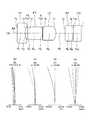
図1は、実施形態に係る内視鏡対物光学系のレンズ断面を示す図である。 FIG. 1 is a diagram illustrating a lens cross section of an endoscope objective optical system according to an embodiment.
本実施形態は、固体撮像素子と組合せる内視鏡対物光学系であって、物体側から順に、物体側に平面を向けた平凹負レンズL1と、フレア絞りFSと、吸収型フィルター(平行平板)F1と、明るさ絞りSと、物体側に平面を向けた平凸正レンズL2と、を有し、以下の条件式(1)を満足することを特徴とする。
0.5≦tg1/tl≦0.8 (1)
ここで、
tg1は、平凹負レンズL1の物体側面から平凸正レンズL2の像側面までの光軸AXに沿った長さ、
tlは、内視鏡対物光学系の全長、即ち、平凹負レンズL1の物体側面から像面までの光軸AXに沿った長さ、
である。The present embodiment is an endoscope objective optical system combined with a solid-state imaging device, and in order from the object side, a plano-concave negative lens L1 having a plane directed toward the object side, a flare stop FS, and an absorption filter (parallel). A flat plate) F1, an aperture stop S, and a planoconvex positive lens L2 having a plane directed toward the object side, and satisfies the following conditional expression (1).
0.5 ≦ tg1 / tl ≦ 0.8 (1)
here,
tg1 is the length along the optical axis AX from the object side surface of the plano-concave negative lens L1 to the image side surface of the plano-convex positive lens L2,
tl is the total length of the endoscope objective optical system, that is, the length along the optical axis AX from the object side surface of the plano-concave negative lens L1 to the image plane,
It is.
パラメータtg1は、パワーを有するレンズのほぼ全てを含む部分の長さに対応する。条件式(1)は、パラメータtg1がレンズ全長に占める割合について規定している。 The parameter tg1 corresponds to the length of the portion including almost all the lenses having power. Conditional expression (1) defines the ratio of the parameter tg1 to the total lens length.
条件式(1)の下限値を下回らないことで、内視鏡対物光学系のバックフォーカスが短くなり全長の短縮化が図れる。また、個々の光学素子の厚さが大きくなり、部品の加工や把持、組立が容易になる。 By not falling below the lower limit value of conditional expression (1), the back focus of the endoscope objective optical system is shortened and the overall length can be shortened. In addition, the thickness of each optical element is increased, which facilitates processing, gripping, and assembly of parts.
また、光学素子の厚さが厚いことは、オートクレーブ時に保持枠から加わる熱応力に対する光学素子の耐久性向上にも寄与する。 Moreover, the thick thickness of the optical element also contributes to improving the durability of the optical element against thermal stress applied from the holding frame during autoclaving.
また、光学素子、例えば吸収型フィルター(平行平板)F1の厚さが厚いことは、所定の波長域のレーザー光を十分な吸収によりカットできる。これにより、例えば、標的用のレーザー光による内視鏡画像のハレーションを防止できる。 In addition, the thick optical element, for example, the absorption filter (parallel plate) F1, can cut a laser beam in a predetermined wavelength region by sufficient absorption. Thereby, for example, it is possible to prevent halation of the endoscopic image by the target laser beam.
さらに、上述したように、内視鏡を、尿路結石治療などのレーザー光による治療に用いる場合、結石にNd−YAGの破砕用レーザー光を照射する。このようなレーザー光も撮像素子に入射すると、内視鏡画像がハレーションしてしまう。 Furthermore, as described above, when the endoscope is used for treatment with laser light such as urinary calculus treatment, the stone is irradiated with Nd-YAG crushing laser light. When such laser light is also incident on the image sensor, the endoscopic image is halated.
このため、吸収型フィルターF1の少なくとも一方の面に、Nd−YAGレーザー光を反射する反射膜をコーティングすることが望ましい。 For this reason, it is desirable to coat at least one surface of the absorption filter F1 with a reflective film that reflects Nd-YAG laser light.
条件式(1)の上限値を上回ると、ピント調整に必要なバックフォーカス長を確保することができない。 If the upper limit of conditional expression (1) is exceeded, the back focus length necessary for focus adjustment cannot be secured.
条件式(1)に代えて、以下の条件式(1’)を満足することが好ましい。
0.5≦tg1/tl≦0.65 (1’)It is preferable to satisfy the following conditional expression (1 ′) instead of conditional expression (1).
0.5 ≦ tg1 / tl ≦ 0.65 (1 ′)
本実施形態の内視鏡対物光学系では、吸収型フィルターは、赤外線吸収フィルターであることが望ましい。 In the endoscope objective optical system of the present embodiment, it is desirable that the absorption filter is an infrared absorption filter.
例えば、標的用のレーザー光として、可視である赤外域のレーザー光を用いることがある。これにより、赤外域のレーザー光をカットすることで、内視鏡画像のハレーションを低減できる。 For example, visible laser light in the infrared region may be used as the target laser light. Thereby, the halation of the endoscopic image can be reduced by cutting the laser beam in the infrared region.
また、本実施形態の内視鏡対物光学系は、以下の条件式(2)、(3)、(4)を満足することが望ましい。
0.32≦tn/φn≦1.4 (2)
0.32≦tIRCF/φIRCF≦1.4 (3)
0.32≦tp/φp≦1.4 (4)
ここで、
tnは、平凹負レンズL1の総肉厚、
φnは、平凹負レンズL1の外径、
tIRCFは、吸収型フィルター(平行平板)F1の肉厚、
φIRCFは、吸収型フィルター(平行平板)F1の外径、
tpは、平凸正レンズL2の総肉厚、
φpは、平凸正レンズL2の外径、
である。
なお、「総肉厚」とは、光学素子の外周部の肉厚をいう。「肉厚」とは、光学素子の光軸上の肉厚をいう。Moreover, it is desirable that the endoscope objective optical system of the present embodiment satisfies the following conditional expressions (2), (3), and (4).
0.32 ≦ tn / φn ≦ 1.4 (2)
0.32 ≦ tIRCF / φIRCF ≦ 1.4 (3)
0.32 ≦ tp / φp ≦ 1.4 (4)
here,
tn is the total thickness of the plano-concave negative lens L1,
φn is the outer diameter of the plano-concave negative lens L1,
tIRCF is the thickness of the absorption filter (parallel plate) F1,
φIRCF is the outer diameter of the absorption filter (parallel plate) F1,
tp is the total thickness of the planoconvex positive lens L2,
φp is the outer diameter of the plano-convex positive lens L2,
It is.
The “total thickness” refers to the thickness of the outer peripheral portion of the optical element. “Thickness” refers to the thickness on the optical axis of the optical element.
条件式(2)、(3)、(4)は、それぞれ平凹負レンズL1、吸収型フィルター(平行平板)F1、平凸正レンズL2の外径と厚さの関係を規定している。 Conditional expressions (2), (3), and (4) define the relationship between the outer diameter and thickness of the plano-concave negative lens L1, the absorption filter (parallel plate) F1, and the plano-convex positive lens L2, respectively.
条件式(2)、(3)、(4)の下限値を下回ると、光学系の加工・組立性が悪化し、かつオートクレーブに対する耐性も低下してしまう。 If the lower limit value of conditional expressions (2), (3), and (4) is not reached, the processing and assembling properties of the optical system will be deteriorated, and the resistance to the autoclave will also be reduced.
また、条件式(2)、(3)、(4)の下限値を下回ると、平凹負レンズL1、吸収型フィルター(平行平板)F1、平凸正レンズL2が傾き偏心を有し、非点収差、コマ収差が発生してしまう。 If the lower limit value of conditional expressions (2), (3), and (4) is not reached, the planoconcave negative lens L1, the absorption filter (parallel plate) F1, and the planoconvex positive lens L2 have tilt decentering and non- Point aberration and coma will occur.
条件式(2)、(3)、(4)の上限値を上回ると、光学系全長の長大化を招いてしまう。 If the upper limit value of conditional expressions (2), (3) and (4) is exceeded, the total length of the optical system will be lengthened.
また、小型な光学系においては、製造誤差によって光学素子と枠との間に素子の外径の4%程度のクリアランスが生じる。光学性能上、クリアランスによるレンズ枠内での光学素子の傾き(チルト)は10°以下に抑えることが望ましい。 In a small optical system, a clearance of about 4% of the outer diameter of the element is generated between the optical element and the frame due to a manufacturing error. In view of optical performance, it is desirable to suppress the tilt of the optical element within the lens frame due to the clearance to 10 ° or less.
図12は、外径φを有する平行平板形状の光学素子Lの鏡枠FRに対する傾きを示す図である。光学素子Lの傾きの角度αを10°以下に抑えるには、(光学素子Lの総肉厚)/(光学素子Lの外径φ)の値は、0.32より大きいことが必要である。 FIG. 12 is a diagram illustrating the inclination of the parallel plate-shaped optical element L having the outer diameter φ with respect to the lens frame FR. In order to suppress the inclination angle α of the optical element L to 10 ° or less, the value of (total thickness of the optical element L) / (outer diameter φ of the optical element L) needs to be larger than 0.32. .
(光学素子Lの肉厚)/(光学素子Lの外径φ)の値、即ち条件式(2)、(3)、(4)の下限値を0.32より大きくすることで、光学素子Lの角度調整が不要になり、組立性が向上する。さらに、光学素子Lの外径に対して肉厚を厚くするとオートクレーブ時に生じる外周部からの応力に対する耐久性も向上する。 By making the value of (thickness of optical element L) / (outer diameter φ of optical element L), that is, the lower limit values of conditional expressions (2), (3), and (4) greater than 0.32, the optical element The angle adjustment of L becomes unnecessary, and the assemblability improves. Furthermore, when the wall thickness is increased with respect to the outer diameter of the optical element L, durability against stress from the outer peripheral portion generated during autoclaving is also improved.
条件式(2)、(3)、(4)に代えて、以下の条件式(2’)、(3’)、(4’)を満足することが好ましい。
0.33≦tn/φn≦1.34 (2’)
0.33≦tIRCF/φIRCF≦1.34 (3’)
0.33≦tp/φp≦1.34 (4’)It is preferable that the following conditional expressions (2 ′), (3 ′), and (4 ′) are satisfied instead of conditional expressions (2), (3), and (4).
0.33 ≦ tn / φn ≦ 1.34 (2 ′)
0.33 ≦ tIRCF / φIRCF ≦ 1.34 (3 ′)
0.33 ≦ tp / φp ≦ 1.34 (4 ′)
また、本実施形態の内視鏡対物光学系は、以下の条件式(2−1)、(3−1)、(4−1)、(4−2)を満足することが望ましい。
0.9<|fn/ft|<2.1 (2−1)
0.15≦tIRCF/tl (3−1)
1.2<|fp/ft|<1.7 (4−1)
0.85<|tp’/rp|<1.3 (4−2)
ここで、
fnは、平凹負レンズL1の焦点距離、
ftは、内視鏡対物光学系全系の焦点距離、
tIRCFは、吸収型フィルター(平行平板)F1の肉厚、
tlは、内視鏡対物光学系の全長、
fpは、平凸正レンズL1の焦点距離、
tp’は、平凸正レンズL1の肉厚、
rpは、平凸正レンズL1の凸面の曲率半径、
である。Moreover, it is desirable that the endoscope objective optical system of the present embodiment satisfies the following conditional expressions (2-1), (3-1), (4-1), and (4-2).
0.9 <| fn / ft | <2.1 (2-1)
0.15 ≦ tIRCF / tl (3-1)
1.2 <| fp / ft | <1.7 (4-1)
0.85 <| tp ′ / rp | <1.3 (4-2)
here,
fn is the focal length of the plano-concave negative lens L1,
ft is the focal length of the entire endoscope objective optical system,
tIRCF is the thickness of the absorption filter (parallel plate) F1,
tl is the total length of the endoscope objective optical system,
fp is the focal length of the planoconvex positive lens L1,
tp ′ is the thickness of the plano-convex positive lens L1,
rp is the radius of curvature of the convex surface of the planoconvex positive lens L1,
It is.
条件式(2−1)は、平凹負レンズL1と内視鏡対物光学系全体のパワー配分を規定している。 Conditional expression (2-1) defines the power distribution of the plano-concave negative lens L1 and the entire endoscope objective optical system.
条件式(2−1)の上限値を上回ると、平凹負レンズL1の物体側の第1面への入射光線高が高くなりフレアが生じてしまう。 When the upper limit of conditional expression (2-1) is exceeded, the height of incident light on the first surface on the object side of the plano-concave negative lens L1 becomes high and flare occurs.
条件式(2−1)の下限値を下回ると、平凹負レンズL1の凹面の曲率が強くなり、レンズの加工性が悪化してしまう。 If the lower limit of conditional expression (2-1) is not reached, the curvature of the concave surface of the plano-concave negative lens L1 will become strong, and the processability of the lens will deteriorate.
条件式(3−1)は、吸収型フィルター(平行平板)F1の厚みと全長の関係を規定している。上述した構成の内視鏡対物光学系において、条件式(3−1)の下限値を下回らないことで、吸収型フィルターの十分な厚さを確保できる。このため、ハレーションの原因となる波長域の光を吸収によりカットし、ハレーションを防ぐことができる。 Conditional expression (3-1) defines the relationship between the thickness and the total length of the absorption filter (parallel plate) F1. In the endoscope objective optical system having the above-described configuration, a sufficient thickness of the absorption filter can be secured by not falling below the lower limit value of the conditional expression (3-1). For this reason, the light in the wavelength region that causes halation can be cut by absorption to prevent halation.
条件式(4−1)は、平凸正レンズL2と内視鏡対物光学系全体のパワー配分を規定している。 Conditional expression (4-1) defines the power distribution of the planoconvex positive lens L2 and the entire endoscope objective optical system.
条件式(4−1)の下限値を下回ると、ピント調整に必要なバックフォーカス長を確保することができない。 If the lower limit of conditional expression (4-1) is not reached, the back focus length necessary for focus adjustment cannot be secured.
条件式(4−1)の上限値を上回ると、平凸正レンズL2のパワーが不足し、光学系全長が長くなってしまう。 If the upper limit of conditional expression (4-1) is exceeded, the power of the planoconvex positive lens L2 will be insufficient, and the total length of the optical system will be long.
条件式(4−2)は、平凸正レンズL2の厚さと曲率半径の関係を規定している。条件式(4−2)の下限値を下回る、または上限値を上回ると、レンズの心取り加工性が悪化してしまう。 Conditional expression (4-2) defines the relationship between the thickness of the planoconvex positive lens L2 and the radius of curvature. If the lower limit value of conditional expression (4-2) is exceeded or the upper limit value is exceeded, the centering processability of the lens will deteriorate.
(実施例1)
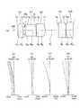
実施例1に係る内視鏡対物光学系について説明する。図2(a)は、本実施例に係る内視鏡対物光学系のレンズ断面図である。Example 1
An endoscope objective optical system according to Example 1 will be described. FIG. 2A is a lens cross-sectional view of the endoscope objective optical system according to the present embodiment.
本実施例では、物体側から順に、平凹負レンズL1と、フレア絞りFSと、平行平板F1と、明るさ絞りSと、平凸正レンズL2と、平行平板F2と、平行平板CGと、から構成される。 In this embodiment, in order from the object side, a plano-concave negative lens L1, a flare stop FS, a parallel plate F1, a brightness stop S, a plano-convex positive lens L2, a parallel plate F2, a parallel plate CG, Consists of
平行平板F1は、赤外線吸収フィルターである。平行平板F2と平行平板CGとは接合されている。d9は接着層である。 The parallel plate F1 is an infrared absorption filter. The parallel plate F2 and the parallel plate CG are joined. d9 is an adhesive layer.
図2(b)、(c)、(d)、(e)は、本実施例の球面収差(SA)、非点収差(AS)、歪曲収差(DT)、倍率色収差(CC)を示す。諸収差図は、656.27nm(C線)、587.56nm(d線)、540.07nm(e線)、486.13nm(F線)及び435.83nm(g線)の各波長について示されている。また、各図中、FNOはFナンバーを、”ω”は半画角を示す。以下、収差図に関しては、同様である。 2B, 2C, 2D, and 2E show the spherical aberration (SA), astigmatism (AS), distortion (DT), and lateral chromatic aberration (CC) of this example. The aberration diagrams are shown for each wavelength of 656.27 nm (C line), 587.56 nm (d line), 540.07 nm (e line), 486.13 nm (F line), and 435.83 nm (g line). ing. In each figure, FNO indicates an F number, and “ω” indicates a half angle of view. The same applies to the aberration diagrams.
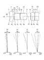
(実施例2)
実施例2に係る内視鏡対物光学系について説明する。図3(a)は、本実施例に係る内視鏡対物光学系のレンズ断面図である。(Example 2)
An endoscope objective optical system according to Example 2 will be described. FIG. 3A is a lens cross-sectional view of the endoscope objective optical system according to the present embodiment.
本実施例では、物体側から順に、平凹負レンズL1と、フレア絞りFSと、平行平板F1と、明るさ絞りSと、平凸正レンズL2と、凸平正レンズL3と、平行平板CGと、から構成される。 In this embodiment, in order from the object side, a plano-concave negative lens L1, a flare stop FS, a parallel plate F1, an aperture stop S, a plano-convex positive lens L2, a convex plano-positive lens L3, and a parallel plate CG Is composed of.
平行平板F1は、赤外線吸収フィルターである。凸平正レンズL3は、フィールドレンズである。凸平正レンズL3と平行平板CGとは接合されている。d9は接着層である。 The parallel plate F1 is an infrared absorption filter. The convex positive lens L3 is a field lens. The convex positive lens L3 and the parallel plate CG are joined. d9 is an adhesive layer.
図3(b)、(c)、(d)、(e)は、本実施例の球面収差(SA)、非点収差(AS)、歪曲収差(DT)、倍率色収差(CC)を示す。 FIGS. 3B, 3C, 3D, and 3E show the spherical aberration (SA), astigmatism (AS), distortion (DT), and lateral chromatic aberration (CC) of this example.
(実施例3)
実施例3に係る内視鏡対物光学系について説明する。図4(a)は、本実施例に係る内視鏡対物光学系のレンズ断面図である。(Example 3)
An endoscope objective optical system according to Example 3 will be described. FIG. 4A is a lens cross-sectional view of the endoscope objective optical system according to the present embodiment.
本実施例では、物体側から順に、平凹負レンズL1と、フレア絞りFSと、平行平板F1と、明るさ絞りSと、平凸正レンズL2と、凸平正レンズL3と、平行平板CGと、から構成される。 In this embodiment, in order from the object side, a plano-concave negative lens L1, a flare stop FS, a parallel plate F1, an aperture stop S, a plano-convex positive lens L2, a convex plano-positive lens L3, and a parallel plate CG Is composed of.
平行平板F1は、赤外線吸収フィルターである。凸平正レンズL3は、フィールドレンズである。凸平正レンズL3と平行平板CGとは接合されている。d9は接着層である。 The parallel plate F1 is an infrared absorption filter. The convex positive lens L3 is a field lens. The convex positive lens L3 and the parallel plate CG are joined. d9 is an adhesive layer.
図4(b)、(c)、(d)、(e)は、本実施例の球面収差(SA)、非点収差(AS)、歪曲収差(DT)、倍率色収差(CC)を示す。 4B, 4C, 4D, and 4E show the spherical aberration (SA), astigmatism (AS), distortion (DT), and lateral chromatic aberration (CC) of this example.
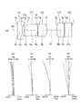
(実施例4)
実施例4に係る内視鏡対物光学系について説明する。図5(a)は、本実施例に係る内視鏡対物光学系のレンズ断面図である。Example 4
An endoscope objective optical system according to Example 4 will be described. FIG. 5A is a lens cross-sectional view of the endoscope objective optical system according to the present example.
本実施例では、物体側から順に、平凹負レンズL1と、フレア絞りFSと、平行平板F1と、明るさ絞りSと、平凸正レンズL2と、平行平板F2と、平行平板CGと、から構成される。 In this embodiment, in order from the object side, a plano-concave negative lens L1, a flare stop FS, a parallel plate F1, a brightness stop S, a plano-convex positive lens L2, a parallel plate F2, a parallel plate CG, Consists of
平行平板F1は、赤外線吸収フィルターである。平行平板F2と平行平板CGとは接合されている。d9は接着層である。 The parallel plate F1 is an infrared absorption filter. The parallel plate F2 and the parallel plate CG are joined. d9 is an adhesive layer.
図5(b)、(c)、(d)、(e)は、本実施例の球面収差(SA)、非点収差(AS)、歪曲収差(DT)、倍率色収差(CC)を示す。 FIGS. 5B, 5C, 5D, and 5E show the spherical aberration (SA), astigmatism (AS), distortion (DT), and lateral chromatic aberration (CC) of this example.
(実施例5)
実施例5に係る内視鏡対物光学系について説明する。図6(a)は、本実施例に係る内視鏡対物光学系のレンズ断面図である。(Example 5)
An endoscope objective optical system according to Example 5 will be described. FIG. 6A is a lens cross-sectional view of the endoscope objective optical system according to the present example.
本実施例では、物体側から順に、平凹負レンズL1と、フレア絞りFSと、平行平板F1と、明るさ絞りSと、平凸正レンズL2と、平行平板F2と、平行平板CGと、から構成される。 In this embodiment, in order from the object side, a plano-concave negative lens L1, a flare stop FS, a parallel plate F1, a brightness stop S, a plano-convex positive lens L2, a parallel plate F2, a parallel plate CG, Consists of
平行平板F1は、赤外線吸収フィルターである。平行平板F2と平行平板CGとは接合されている。d9は接着層である。 The parallel plate F1 is an infrared absorption filter. The parallel plate F2 and the parallel plate CG are joined. d9 is an adhesive layer.
図6(b)、(c)、(d)、(e)は、本実施例の球面収差(SA)、非点収差(AS)、歪曲収差(DT)、倍率色収差(CC)を示す。 FIGS. 6B, 6C, 6D, and 6E show the spherical aberration (SA), astigmatism (AS), distortion (DT), and lateral chromatic aberration (CC) of this example.
(実施例6)
実施例6に係る内視鏡対物光学系について説明する。図7(a)は、本実施例に係る内視鏡対物光学系のレンズ断面図である。(Example 6)
An endoscope objective optical system according to Example 6 will be described. FIG. 7A is a lens cross-sectional view of the endoscope objective optical system according to the present example.
本実施例では、物体側から順に、平凹負レンズL1と、フレア絞りFSと、平行平板F1と、明るさ絞りSと、平凸正レンズL2と、平行平板F2と、平行平板CGと、から構成される。 In this embodiment, in order from the object side, a plano-concave negative lens L1, a flare stop FS, a parallel plate F1, a brightness stop S, a plano-convex positive lens L2, a parallel plate F2, a parallel plate CG, Consists of
平行平板F1は、赤外線吸収フィルターである。平行平板F2と平行平板CGとは接合されている。d9は接着層である。 The parallel plate F1 is an infrared absorption filter. The parallel plate F2 and the parallel plate CG are joined. d9 is an adhesive layer.
図7(b)、(c)、(d)、(e)は、本実施例の球面収差(SA)、非点収差(AS)、歪曲収差(DT)、倍率色収差(CC)を示す。 FIGS. 7B, 7C, 7D, and 7E show the spherical aberration (SA), astigmatism (AS), distortion (DT), and lateral chromatic aberration (CC) of this example.
(実施例7)
実施例7に係る内視鏡対物光学系について説明する。図8(a)は、本実施例に係る内視鏡対物光学系のレンズ断面図である。(Example 7)
An endoscope objective optical system according to Example 7 will be described. FIG. 8A is a lens cross-sectional view of the endoscope objective optical system according to the present example.
本実施例では、物体側から順に、平凹負レンズL1と、フレア絞りFSと、平行平板F1と、明るさ絞りSと、平凸正レンズL2と、平行平板F2と、平行平板CGと、から構成される。 In this embodiment, in order from the object side, a plano-concave negative lens L1, a flare stop FS, a parallel plate F1, a brightness stop S, a plano-convex positive lens L2, a parallel plate F2, a parallel plate CG, Consists of
平行平板F1は、赤外線吸収フィルターである。平行平板F2と平行平板CGとは接合されている。d9は接着層である。 The parallel plate F1 is an infrared absorption filter. The parallel plate F2 and the parallel plate CG are joined. d9 is an adhesive layer.
図8(b)、(c)、(d)、(e)は、本実施例の球面収差(SA)、非点収差(AS)、歪曲収差(DT)、倍率色収差(CC)を示す。 8B, 8C, 8D, and 8E show the spherical aberration (SA), astigmatism (AS), distortion (DT), and lateral chromatic aberration (CC) of this example.
(実施例8)
実施例8に係る内視鏡対物光学系について説明する。図9(a)は、本実施例に係る内視鏡対物光学系のレンズ断面図である。(Example 8)
An endoscope objective optical system according to Example 8 will be described. FIG. 9A is a lens cross-sectional view of the endoscope objective optical system according to the present example.
本実施例では、物体側から順に、平凹負レンズL1と、フレア絞りFSと、平行平板F1と、明るさ絞りSと、平凸正レンズL2と、平行平板F2と、平行平板CGと、から構成される。 In this embodiment, in order from the object side, a plano-concave negative lens L1, a flare stop FS, a parallel plate F1, a brightness stop S, a plano-convex positive lens L2, a parallel plate F2, a parallel plate CG, Consists of
平行平板F1は、赤外線吸収フィルターである。平行平板F2と平行平板CGとは接合されている。d9は接着層である。 The parallel plate F1 is an infrared absorption filter. The parallel plate F2 and the parallel plate CG are joined. d9 is an adhesive layer.
図9(b)、(c)、(d)、(e)は、本実施例の球面収差(SA)、非点収差(AS)、歪曲収差(DT)、倍率色収差(CC)を示す。 FIGS. 9B, 9C, 9D, and 9E show the spherical aberration (SA), astigmatism (AS), distortion (DT), and lateral chromatic aberration (CC) of this example.
(実施例9)
実施例9に係る内視鏡対物光学系について説明する。図10(a)は、本実施例に係る内視鏡対物光学系のレンズ断面図である。Example 9
An endoscope objective optical system according to Example 9 will be described. FIG. 10A is a lens cross-sectional view of the endoscope objective optical system according to the present example.
本実施例では、物体側から順に、平凹負レンズL1と、フレア絞りFSと、平行平板F1と、明るさ絞りSと、平凸正レンズL2と、平行平板F2と、平行平板CGと、から構成される。 In this embodiment, in order from the object side, a plano-concave negative lens L1, a flare stop FS, a parallel plate F1, a brightness stop S, a plano-convex positive lens L2, a parallel plate F2, a parallel plate CG, Consists of
平行平板F1は、赤外線吸収フィルターである。平行平板F2と平行平板CGとは接合されている。d9は接着層である。 The parallel plate F1 is an infrared absorption filter. The parallel plate F2 and the parallel plate CG are joined. d9 is an adhesive layer.
図10(b)、(c)、(d)、(e)は、本実施例の球面収差(SA)、非点収差(AS)、歪曲収差(DT)、倍率色収差(CC)を示す。 FIGS. 10B, 10C, 10D, and 10E show the spherical aberration (SA), astigmatism (AS), distortion (DT), and lateral chromatic aberration (CC) of this example.
(実施例10)
実施例10に係る内視鏡対物光学系について説明する。図11(a)は、本実施例に係る内視鏡対物光学系のレンズ断面図である。(Example 10)
An endoscope objective optical system according to Example 10 will be described. FIG. 11A is a lens cross-sectional view of the endoscope objective optical system according to the present example.
本実施例では、物体側から順に、平凹負レンズL1と、フレア絞りFSと、平行平板F1と、明るさ絞りSと、平凸正レンズL2と、凸平正レンズL3と、平行平板CGと、から構成される。 In this embodiment, in order from the object side, a plano-concave negative lens L1, a flare stop FS, a parallel plate F1, an aperture stop S, a plano-convex positive lens L2, a convex plano-positive lens L3, and a parallel plate CG Is composed of.
平行平板F1は、赤外線吸収フィルターである。凸平正レンズL3は、フィールドレンズである。凸平正レンズL3と平行平板CGとは接合されている。d9は接着層である。 The parallel plate F1 is an infrared absorption filter. The convex positive lens L3 is a field lens. The convex positive lens L3 and the parallel plate CG are joined. d9 is an adhesive layer.
図11(b)、(c)、(d)、(e)は、本実施例の球面収差(SA)、非点収差(AS)、歪曲収差(DT)、倍率色収差(CC)を示す。 11 (b), (c), (d), and (e) show the spherical aberration (SA), astigmatism (AS), distortion (DT), and lateral chromatic aberration (CC) of this example.
以下に、上記各実施例の数値データを示す。記号は、rは各レンズ面の曲率半径、dは各レンズ面間の間隔、neは各レンズのe線の屈折率、νdは各レンズのアッベ数、FnoはFナンバー、ωは半画角、IHは像高である。また、ERは有効直径、FSはフレア絞り、Sは明るさ絞りである。T650は650nmにおける吸収型フィルターの内部透過率である。Below, the numerical data of each said Example are shown. Symbols r are the radius of curvature of each lens surface, d is the distance between the lens surfaces, ne is the refractive index of the e-line of each lens, νd is the Abbe number of each lens, Fno is the F number, and ω is the half field angle , IH is the image height. ER is an effective diameter, FS is a flare stop, and S is a brightness stop. T650 is the internal transmittance of the absorption filter at650 nm.
数値実施例1
単位 mm
面データ
面番号 r d ne νd ER
1 ∞ 0.200 1.77066 71.79 0.80
2 0.300 0.100
3 (FS) ∞ 0.030 0.30
4 ∞ 0.450 1.52300 65.13 0.50
5 (S) ∞ 0.010 0.17
6 ∞ 0.410 1.88815 40.76 0.55
7 -0.427 0.474
8 ∞ 0.300 1.51825 64.14 0.62
9 ∞ 0.020 1.50688 64.00 0.62
10 ∞ 0.300 1.61350 50.49 0.62
像面 ∞
各種データ
焦点距離 (mm) 0.334
視野角 (°) 90.6
Fno 4.186
T650 (%) 12.28
tl (mm) 2.29
Numerical example 1
Unit mm
Surface data surface number rd ne νd ER
1 ∞ 0.200 1.77066 71.79 0.80
2 0.300 0.100
3 (FS) ∞ 0.030 0.30
4 ∞ 0.450 1.52300 65.13 0.50
5 (S) ∞ 0.010 0.17
6 ∞ 0.410 1.88815 40.76 0.55
7 -0.427 0.474
8 ∞ 0.300 1.51825 64.14 0.62
9 ∞ 0.020 1.50688 64.00 0.62
10 ∞ 0.300 1.61350 50.49 0.62
Image plane ∞
Various data focal length (mm) 0.334
Viewing angle (°) 90.6
Fno 4.186
T650 (%) 12.28
tl (mm) 2.29
数値実施例2
単位 mm
面データ
面番号 r d ne νd ER
1 ∞ 0.200 1.77066 71.79 0.80
2 0.300 0.090
3 (FS) ∞ 0.030 0.30
4 ∞ 0.450 1.52300 65.13 0.50
5 (S) ∞ 0.010 0.16
6 ∞ 0.390 1.88815 40.76 0.55
7 -0.459 0.520
8 0.951 0.340 1.51825 64.14 0.65
9 ∞ 0.020 1.50688 64.00 0.65
10 ∞ 0.300 1.61350 50.49 0.65
像面 ∞
各種データ
焦点距離 (mm) 0.310
視野角 (°) 96.9
Fno 4.079
T650 (%) 12.28
tl (mm) 2.35
Numerical example 2
Unit mm
Surface data surface number rd ne νd ER
1 ∞ 0.200 1.77066 71.79 0.80
2 0.300 0.090
3 (FS) ∞ 0.030 0.30
4 ∞ 0.450 1.52300 65.13 0.50
5 (S) ∞ 0.010 0.16
6 ∞ 0.390 1.88815 40.76 0.55
7 -0.459 0.520
8 0.951 0.340 1.51825 64.14 0.65
9 ∞ 0.020 1.50688 64.00 0.65
10 ∞ 0.300 1.61350 50.49 0.65
Image plane ∞
Various data focal length (mm) 0.310
Viewing angle (°) 96.9
Fno 4.079
T650 (%) 12.28
tl (mm) 2.35
数値実施例3
単位 mm
面データ
面番号 r d ne νd ER
1 ∞ 0.210 1.77066 71.79 0.80
2 0.408 0.050
3 (FS) ∞ 0.030 0.32
4 ∞ 0.360 1.52300 65.13 0.80
5 (S) ∞ 0.010 0.13
6 ∞ 0.350 1.88815 40.76 0.60
7 -0.374 0.300
8 2.963 0.300 1.51825 64.14 0.62
9 ∞ 0.020 1.50688 64.00 0.62
10 ∞ 0.300 1.61350 50.49 0.62
像面 ∞
各種データ
焦点距離 (mm) 0.336
視野角 (°) 87.5
Fno 4.182
T650 (%) 18.67
tl (mm) 1.93
Numerical Example 3
Unit mm
Surface data surface number rd ne νd ER
1 ∞ 0.210 1.77066 71.79 0.80
2 0.408 0.050
3 (FS) ∞ 0.030 0.32
4 ∞ 0.360 1.52300 65.13 0.80
5 (S) ∞ 0.010 0.13
6 ∞ 0.350 1.88815 40.76 0.60
7 -0.374 0.300
8 2.963 0.300 1.51825 64.14 0.62
9 ∞ 0.020 1.50688 64.00 0.62
10 ∞ 0.300 1.61350 50.49 0.62
Image plane ∞
Various data focal length (mm) 0.336
Viewing angle (°) 87.5
Fno 4.182
T650 (%) 18.67
tl (mm) 1.93
数値実施例4
単位 mm
面データ
面番号 r d ne νd ER
1 ∞ 0.300 1.77066 71.79 0.80
2 0.540 0.050
3 (FS) ∞ 0.030 0.36
4 ∞ 0.450 1.52300 65.13 0.50
5 (S) ∞ 0.010 0.17
6 ∞ 0.500 1.88815 40.76 0.55
7 -0.390 0.271
8 ∞ 0.300 1.51825 64.14 0.62
9 ∞ 0.020 1.50688 64.00 0.62
10 ∞ 0.300 1.61350 50.49 0.62
像面 ∞
各種データ
焦点距離 (mm) 0.337
視野角 (°) 87.7
Fno 3.082
T650 (%) 12.28
tl (mm) 2.23
Numerical Example 4
Unit mm
Surface data surface number rd ne νd ER
1 ∞ 0.300 1.77066 71.79 0.80
2 0.540 0.050
3 (FS) ∞ 0.030 0.36
4 ∞ 0.450 1.52300 65.13 0.50
5 (S) ∞ 0.010 0.17
6 ∞ 0.500 1.88815 40.76 0.55
7 -0.390 0.271
8 ∞ 0.300 1.51825 64.14 0.62
9 ∞ 0.020 1.50688 64.00 0.62
10 ∞ 0.300 1.61350 50.49 0.62
Image plane ∞
Various data focal length (mm) 0.337
Viewing angle (°) 87.7
Fno 3.082
T650 (%) 12.28
tl (mm) 2.23
数値実施例5
単位 mm
面データ
面番号 r d ne νd ER
1 ∞ 0.300 1.77066 71.79 0.80
2 0.492 0.070
3 (FS) ∞ 0.030 0.40
4 ∞ 0.570 1.52300 65.13 0.50
5 (S) ∞ 0.010 0.14
6 ∞ 0.500 1.88815 40.76 0.55
7 -0.424 0.346
8 ∞ 0.300 1.51825 64.14 0.62
9 ∞ 0.020 1.50688 64.00 0.62
10 ∞ 0.300 1.61350 50.49 0.62
像面 ∞
各種データ
焦点距離 (mm) 0.335
視野角 (°) 87.7
Fno 4.214
T650 (%) 7.02
tl (mm) 2.45
Numerical Example 5
Unit mm
Surface data surface number rd ne νd ER
1 ∞ 0.300 1.77066 71.79 0.80
2 0.492 0.070
3 (FS) ∞ 0.030 0.40
4 ∞ 0.570 1.52300 65.13 0.50
5 (S) ∞ 0.010 0.14
6 ∞ 0.500 1.88815 40.76 0.55
7 -0.424 0.346
8 ∞ 0.300 1.51825 64.14 0.62
9 ∞ 0.020 1.50688 64.00 0.62
10 ∞ 0.300 1.61350 50.49 0.62
Image plane ∞
Various data focal length (mm) 0.335
Viewing angle (°) 87.7
Fno 4.214
T650 (%) 7.02
tl (mm) 2.45
数値実施例6
単位 mm
面データ
面番号 r d ne νd ER
1 ∞ 0.200 1.77066 71.79 0.80
2 0.476 0.070
3 (FS) ∞ 0.030 0.42
4 ∞ 0.670 1.52300 65.13 0.50
5 (S) ∞ 0.010 0.15
6 ∞ 0.390 1.88815 40.76 0.55
7 -0.428 0.361
8 ∞ 0.300 1.51825 64.14 0.62
9 ∞ 0.020 1.50688 64.00 0.62
10 ∞ 0.300 1.61350 50.49 0.62
像面 ∞
各種データ
焦点距離 (mm) 0.334
視野角 (°) 87.2
Fno 4.213
T650 (%) 4.40
tl (mm) 2.35
Numerical Example 6
Unit mm
Surface data surface number rd ne νd ER
1 ∞ 0.200 1.77066 71.79 0.80
2 0.476 0.070
3 (FS) ∞ 0.030 0.42
4 ∞ 0.670 1.52300 65.13 0.50
5 (S) ∞ 0.010 0.15
6 ∞ 0.390 1.88815 40.76 0.55
7 -0.428 0.361
8 ∞ 0.300 1.51825 64.14 0.62
9 ∞ 0.020 1.50688 64.00 0.62
10 ∞ 0.300 1.61350 50.49 0.62
Image plane ∞
Various data focal length (mm) 0.334
Viewing angle (°) 87.2
Fno 4.213
T650 (%) 4.40
tl (mm) 2.35
数値実施例7
単位 mm
面データ
面番号 r d ne νd ER
1 ∞ 0.200 1.77066 71.79 0.60
2 0.270 0.090
3 (FS) ∞ 0.030 0.28
4 ∞ 0.450 1.52300 65.13 0.50
5 (S) ∞ 0.010 0.18
6 ∞ 0.390 1.88815 40.76 0.55
7 -0.425 0.554
8 ∞ 0.300 1.51825 64.14 0.65
9 ∞ 0.020 1.50688 64.00 0.65
10 ∞ 0.300 1.61350 50.49 0.65
像面 ∞
各種データ
焦点距離 (mm) 0.333
視野角 (°) 87.7
Fno 4.133
T650 (%) 12.28
tl (mm) 2.34
Numerical Example 7
Unit mm
Surface data surface number rd ne νd ER
1 ∞ 0.200 1.77066 71.79 0.60
2 0.270 0.090
3 (FS) ∞ 0.030 0.28
4 ∞ 0.450 1.52300 65.13 0.50
5 (S) ∞ 0.010 0.18
6 ∞ 0.390 1.88815 40.76 0.55
7 -0.425 0.554
8 ∞ 0.300 1.51825 64.14 0.65
9 ∞ 0.020 1.50688 64.00 0.65
10 ∞ 0.300 1.61350 50.49 0.65
Image plane ∞
Various data focal length (mm) 0.333
Viewing angle (°) 87.7
Fno 4.133
T650 (%) 12.28
tl (mm) 2.34
数値実施例8
単位 mm
面データ
面番号 r d ne νd ER
1 ∞ 0.480 2.01169 28.27 0.60
2 0.44 0.050
3 (FS) ∞ 0.030 0.24
4 ∞ 0.450 1.52300 65.13 0.50
5 (S) ∞ 0.010 0.20
6 ∞ 0.390 1.80922 39.59 0.55
7 -0.416 0.650
8 ∞ 0.300 1.51825 64.14 0.65
9 ∞ 0.020 1.50688 64.00 0.65
10 ∞ 0.300 1.61350 50.49 0.65
像面 ∞
各種データ
焦点距離 (mm) 0.428
視野角 (°) 66.0
Fno 4.063
T650 (%) 12.28
tl (mm) 2.68
Numerical Example 8
Unit mm
Surface data surface number rd ne νd ER
1 ∞ 0.480 2.01169 28.27 0.60
2 0.44 0.050
3 (FS) ∞ 0.030 0.24
4 ∞ 0.450 1.52300 65.13 0.50
5 (S) ∞ 0.010 0.20
6 ∞ 0.390 1.80922 39.59 0.55
7 -0.416 0.650
8 ∞ 0.300 1.51825 64.14 0.65
9 ∞ 0.020 1.50688 64.00 0.65
10 ∞ 0.300 1.61350 50.49 0.65
Image plane ∞
Various data focal length (mm) 0.428
Viewing angle (°) 66.0
Fno 4.063
T650 (%) 12.28
tl (mm) 2.68
数値実施例9
単位 mm
面データ
面番号 r d ne νd ER
1 ∞ 0.300 2.01169 28.27 0.80
2 0.718 0.050
3 (FS) ∞ 0.030 0.36
4 ∞ 0.430 1.52300 65.13 0.50
5 (S) ∞ 0.010 0.12
6 ∞ 0.550 2.01169 28.27 0.50
7 -0.446 0.273
8 ∞ 0.300 1.51825 64.14 0.62
9 ∞ 0.020 1.50688 64.00 0.62
10 ∞ 0.300 1.61350 50.49 0.62
像面 ∞
各種データ
焦点距離 (mm) 0.342
視野角 (°) 87.5
Fno 4.349
T650 (%) 13.48
tl (mm) 2.26
Numerical Example 9
Unit mm
Surface data surface number rd ne νd ER
1 ∞ 0.300 2.01169 28.27 0.80
2 0.718 0.050
3 (FS) ∞ 0.030 0.36
4 ∞ 0.430 1.52300 65.13 0.50
5 (S) ∞ 0.010 0.12
6 ∞ 0.550 2.01169 28.27 0.50
7 -0.446 0.273
8 ∞ 0.300 1.51825 64.14 0.62
9 ∞ 0.020 1.50688 64.00 0.62
10 ∞ 0.300 1.61350 50.49 0.62
Image plane ∞
Various data focal length (mm) 0.342
Viewing angle (°) 87.5
Fno 4.349
T650 (%) 13.48
tl (mm) 2.26
数値実施例10
単位 mm
面データ
面番号 r d ne νd ER
1 ∞ 0.200 1.77066 71.79 0.80
2 0.420 0.070
3 (FS) ∞ 0.030 0.42
4 ∞ 0.560 1.52300 65.13 0.50
5 (S) ∞ 0.010 0.15
6 ∞ 0.390 1.88815 40.76 0.55
7 -0.440 0.410
8 2.100 0.300 1.51825 64.14 0.62
9 ∞ 0.020 1.50688 64.00 0.62
10 ∞ 0.300 1.61350 50.49 0.62
像面 ∞
各種データ
焦点距離 (mm) 0.333
視野角 (°) 87.7
Fno 4.182
T650 (%) 7.35
tl (mm) 2.29
Numerical Example 10
Unit mm
Surface data surface number rd ne νd ER
1 ∞ 0.200 1.77066 71.79 0.80
2 0.420 0.070
3 (FS) ∞ 0.030 0.42
4 ∞ 0.560 1.52300 65.13 0.50
5 (S) ∞ 0.010 0.15
6 ∞ 0.390 1.88815 40.76 0.55
7 -0.440 0.410
8 2.100 0.300 1.51825 64.14 0.62
9 ∞ 0.020 1.50688 64.00 0.62
10 ∞ 0.300 1.61350 50.49 0.62
Image plane ∞
Various data focal length (mm) 0.333
Viewing angle (°) 87.7
Fno 4.182
T650 (%) 7.35
tl (mm) 2.29
各実施例の条件式対応値を以下に示す。
条件式 実施例1 実施例2 実施例3 実施例4 実施例5
(1) tg1/tl 0.52 0.50 0.52 0.60 0.61
(2) tn/φn 0.38 0.36 0.33 0.44 0.46
(3) tIRCF/φIRCF 0.90 0.90 0.45 0.90 1.14
(4) tp/φp 0.56 0.54 0.33 0.70 0.72
(2-1) |fn/ft| 1.17 1.26 1.58 2.08 1.91
(3-1) tIRCF/tl 0.20 0.19 0.19 0.20 0.23
(4-1) |fp/ft| 1.44 1.67 1.25 1.30 1.43
(4-2) |tp'/rp| 0.96 0.85 0.94 1.28 1.18
条件式 実施例6 実施例7 実施例8 実施例9 実施例10
(1) tg1/tl 0.58 0.50 0.53 0.61 0.55
(2) tn/φn 0.53 0.53 0.52 0.95 0.53
(3) tIRCF/φIRCF 1.34 0.90 0.90 0.86 1.12
(4) tp/φp 0.71 0.71 0.71 1.10 0.71
(2-1) |fn/ft| 1.85 1.05 1.02 2.07 1.63
(3-1) tIRCF/tl 0.28 0.19 0.17 0.19 0.24
(4-1) |fp/ft| 1.44 1.44 1.20 1.29 1.49
(4-2) |tp'/rp| 0.91 0.92 0.94 1.23 0.89
The values corresponding to the conditional expressions in each example are shown below.
Conditional Example 1 Example 2 Example 3 Example 4 Example 5
(1) tg1 / tl 0.52 0.50 0.52 0.60 0.61
(2) tn / φn 0.38 0.36 0.33 0.44 0.46
(3) tIRCF / φIRCF 0.90 0.90 0.45 0.90 1.14
(4) tp / φp 0.56 0.54 0.33 0.70 0.72
(2-1) | fn / ft | 1.17 1.26 1.58 2.08 1.91
(3-1) tIRCF / tl 0.20 0.19 0.19 0.20 0.23
(4-1) | fp / ft | 1.44 1.67 1.25 1.30 1.43
(4-2) | tp '/ rp | 0.96 0.85 0.94 1.28 1.18
Conditional Example Example 6 Example 7 Example 8 Example 9 Example 10
(1) tg1 / tl 0.58 0.50 0.53 0.61 0.55
(2) tn / φn 0.53 0.53 0.52 0.95 0.53
(3) tIRCF / φIRCF 1.34 0.90 0.90 0.86 1.12
(4) tp / φp 0.71 0.71 0.71 1.10 0.71
(2-1) | fn / ft | 1.85 1.05 1.02 2.07 1.63
(3-1) tIRCF / tl 0.28 0.19 0.17 0.19 0.24
(4-1) | fp / ft | 1.44 1.44 1.20 1.29 1.49
(4-2) | tp '/ rp | 0.91 0.92 0.94 1.23 0.89
以上、本発明の種々の実施形態について説明したが、本発明は、これらの実施形態のみに限られるものではなく、その趣旨を逸脱しない範囲で、これら実施形態の構成を適宜組合せて構成した実施形態も本発明の範疇となるものである。 Although various embodiments of the present invention have been described above, the present invention is not limited to these embodiments, and may be implemented by appropriately combining the configurations of these embodiments without departing from the spirit of the present invention. The form is also within the scope of the present invention.
以上のように、本発明は、レーザー光によるハレーションを防止し、光学系の全長が短く、かつレンズの加工・組立が容易であり、オートクレーブ時の温度変化に耐性を有する内視鏡対物光学系に有用である。 As described above, the present invention is an endoscope objective optical system that prevents halation due to laser light, has a short overall optical system length, is easy to process and assemble lenses, and is resistant to temperature changes during autoclaving. Useful for.
L1、L2 レンズ
F1、F2、CG 平行平板
FS フレア絞り
S 明るさ絞り
AX 光軸
I 像面L1, L2 Lens F1, F2, CG Parallel plate FS Flare stop S Brightness stop AX Optical axis I Image plane
Claims (3)
Translated fromJapanese物体側から順に、平凹負レンズと、吸収型フィルターと、明るさ絞りと、平凸正レンズと、を有し、以下の条件式(1)、(2−1)、(3−1)、(4−1)、(4−2)を満足することを特徴とする内視鏡対物光学系。
0.5≦tg1/tl≦0.8 (1)
0.9<|fn/ft|<2.1 (2−1)
0.15≦tIRCF/tl (3−1)
1.2<|fp/ft|<1.7 (4−1)
0.85<|tp’/rp|<1.3 (4−2)
ここで、
tg1は、前記平凹負レンズの物体側面から前記平凸正レンズの像側面までの光軸に沿った長さ、
tlは、前記内視鏡対物光学系の全長、
fnは、前記平凹負レンズの焦点距離、
ftは、前記内視鏡対物光学系全系の焦点距離、
tIRCFは、前記吸収型フィルターの光軸上の厚み、
fpは、前記平凸正レンズの焦点距離、
tp’は、前記平凸正レンズの光軸上の厚み、
rpは、前記平凸正レンズの凸面の曲率半径、
である。An endoscope objective optical system combined with a solid-state image sensor,
In order from the object side, there are a plano-concave negative lens, an absorption filter, an aperture stop, and a plano-convex positive lens, and the following conditional expressions (1),(2-1), (3-1)(4-1) and (4-2) are satisfied.
0.5 ≦ tg1 / tl ≦ 0.8 (1)
0.9 <| fn / ft | <2.1 (2-1)
0.15 ≦ tIRCF / tl (3-1)
1.2 <| fp / ft | <1.7 (4-1)
0.85 <| tp ′ / rp | <1.3 (4-2)
here,
tg1 is the length along the optical axis from the object side surface of the plano-concave negative lens to the image side surface of the plano-convex positive lens;
tl is the total length of the endoscope objective optical system,
fn is a focal length of the plano-concave negative lens;
ft is the focal length of the entire endoscope objective optical system;
tIRCF isthe thickness on the optical axis of the absorption filter,
fp is the focal length of the plano-convex positive lens,
tp ′ is the thickness on the optical axis of the planoconvex positive lens,
rp is the radius of curvature of the convex surface of the planoconvex positive lens,
It is.
0.32≦tn/φn≦1.4 (2)
0.32≦tIRCF/φIRCF≦1.4 (3)
0.32≦tp/φp≦1.4 (4)
ここで、
tnは、前記平凹負レンズの外周部の厚み、
φnは、前記平凹負レンズの外径、
tIRCFは、前記吸収型フィルターの光軸上の厚み、
φIRCFは、前記吸収型フィルターの外径、
tpは、前記平凸正レンズの外周部の厚み、
φpは、前記平凸正レンズの外径、
である。The endoscope objective optical system according to claim 1, wherein the following conditional expressions (2), (3), and (4) are satisfied.
0.32 ≦ tn / φn ≦ 1.4 (2)
0.32 ≦ tIRCF / φIRCF ≦ 1.4 (3)
0.32 ≦ tp / φp ≦ 1.4 (4)
here,
tn isthe thickness of theouter periphery of the plano-concave negative lens;
φn is the outer diameter of the plano-concave negative lens,
tIRCF isthe thickness on the optical axis of the absorption filter,
φIRCF is the outer diameter of the absorption filter,
tp isthe thickness of theouter periphery of the planoconvex positive lens,
φp is the outer diameter of the plano-convex positive lens,
It is.
Applications Claiming Priority (3)
| Application Number | Priority Date | Filing Date | Title |
|---|---|---|---|
| JP2015230522 | 2015-11-26 | ||
| JP2015230522 | 2015-11-26 | ||
| PCT/JP2016/080773WO2017090342A1 (en) | 2015-11-26 | 2016-10-18 | Endoscope objective optical system |
Publications (2)
| Publication Number | Publication Date |
|---|---|
| JP6227201B2true JP6227201B2 (en) | 2017-11-08 |
| JPWO2017090342A1 JPWO2017090342A1 (en) | 2017-11-24 |
Family
ID=58763402
Family Applications (1)
| Application Number | Title | Priority Date | Filing Date |
|---|---|---|---|
| JP2017525422AActiveJP6227201B2 (en) | 2015-11-26 | 2016-10-18 | Endoscope objective optical system |
Country Status (5)
| Country | Link |
|---|---|
| US (1) | US10809523B2 (en) |
| EP (1) | EP3382438A1 (en) |
| JP (1) | JP6227201B2 (en) |
| CN (1) | CN108139567B (en) |
| WO (1) | WO2017090342A1 (en) |
Families Citing this family (4)
| Publication number | Priority date | Publication date | Assignee | Title |
|---|---|---|---|---|
| US10620424B1 (en)* | 2016-09-16 | 2020-04-14 | Precision Optics Corporation, Inc. | Lens for use with imaging sensors |
| JP6463566B1 (en)* | 2017-06-02 | 2019-02-06 | オリンパス株式会社 | Endoscope objective optical system, endoscope and endoscope system |
| CN110251049B (en) | 2019-06-14 | 2021-05-04 | 江西联创电子有限公司 | Endoscope lens |
| CN110596878B (en)* | 2019-10-14 | 2021-11-16 | 南京大学 | Double-lens microscope system with ultra-short focal length |
Family Cites Families (13)
| Publication number | Priority date | Publication date | Assignee | Title |
|---|---|---|---|---|
| JP2558333B2 (en)* | 1988-09-06 | 1996-11-27 | オリンパス光学工業株式会社 | Endoscope objective optical system |
| JPH08286128A (en)* | 1995-04-17 | 1996-11-01 | Olympus Optical Co Ltd | Objective optical system for endoscope |
| JPH09325285A (en)* | 1996-05-31 | 1997-12-16 | Olympus Optical Co Ltd | Endoscopic objective lens |
| US6252723B1 (en)* | 1998-03-03 | 2001-06-26 | Olympus Optical Co., Ltd. | Objective optical system |
| JP2001059937A (en)* | 1999-08-24 | 2001-03-06 | Olympus Optical Co Ltd | Objective lens |
| JP4472130B2 (en)* | 2000-07-14 | 2010-06-02 | オリンパス株式会社 | Endoscope device |
| US7280283B1 (en)* | 2006-05-17 | 2007-10-09 | Olympus Corporation | Endoscopic objective optical system, and imaging system using the same |
| US7869140B2 (en) | 2007-04-13 | 2011-01-11 | Karl Storz Imaging, Inc. | Objective lens design for miniature endoscope |
| JP2009288682A (en) | 2008-05-30 | 2009-12-10 | Olympus Medical Systems Corp | Objective optical system for endoscopes |
| JP5107144B2 (en) | 2008-06-06 | 2012-12-26 | オリンパスメディカルシステムズ株式会社 | Objective optical system and endoscope |
| JP5558058B2 (en)* | 2008-09-19 | 2014-07-23 | オリンパスメディカルシステムズ株式会社 | Endoscopic endoscope |
| CN101726832B (en)* | 2008-10-31 | 2011-09-07 | 比亚迪股份有限公司 | Lens assembly of endoscope |
| WO2014017031A1 (en)* | 2012-07-23 | 2014-01-30 | 富士フイルム株式会社 | Endoscope objective lens and endoscope |
- 2016
- 2016-10-18JPJP2017525422Apatent/JP6227201B2/enactiveActive
- 2016-10-18CNCN201680059435.0Apatent/CN108139567B/enactiveActive
- 2016-10-18EPEP16868291.2Apatent/EP3382438A1/ennot_activeWithdrawn
- 2016-10-18WOPCT/JP2016/080773patent/WO2017090342A1/ennot_activeCeased
- 2018
- 2018-04-17USUS15/955,227patent/US10809523B2/enactiveActive
Also Published As
| Publication number | Publication date |
|---|---|
| WO2017090342A1 (en) | 2017-06-01 |
| US10809523B2 (en) | 2020-10-20 |
| EP3382438A1 (en) | 2018-10-03 |
| CN108139567B (en) | 2020-09-22 |
| US20180231763A1 (en) | 2018-08-16 |
| CN108139567A (en) | 2018-06-08 |
| JPWO2017090342A1 (en) | 2017-11-24 |
Similar Documents
| Publication | Publication Date | Title |
|---|---|---|
| JP6081683B1 (en) | Endoscope objective optical system | |
| JP6313241B2 (en) | Endoscope objective lens and endoscope | |
| JP5031930B2 (en) | Endoscope objective lens and endoscope using the same | |
| JP4685510B2 (en) | Endoscope objective lens | |
| JP3051035B2 (en) | Objective lens for endoscope | |
| JP6227201B2 (en) | Endoscope objective optical system | |
| JP4229754B2 (en) | Objective lens and endoscope using the same | |
| JP5989292B1 (en) | Endoscope objective optical system | |
| JP6368065B1 (en) | Endoscope objective optical system | |
| JP5274728B2 (en) | Endoscope objective optical system | |
| JP2009536553A (en) | Optical assembly for medical imaging devices | |
| WO2018042797A1 (en) | Objective optical system for endoscope | |
| JP5107144B2 (en) | Objective optical system and endoscope | |
| JPWO2018235352A1 (en) | Objective optical system for endoscope | |
| JP4197897B2 (en) | Imaging optical system and endoscope using the same | |
| JP6720026B2 (en) | Objective optical system for endoscope | |
| JP2002365535A (en) | Objective lens for endoscope | |
| JP2005148508A (en) | Objective lens for endoscope | |
| JP6774811B2 (en) | Objective optical system for endoscopes and endoscopes | |
| JP2000187155A (en) | Objective optical system for endoscope | |
| JP7047075B2 (en) | Endoscope objective optical system, image pickup device and endoscope | |
| JP3590439B2 (en) | Endoscope objective lens | |
| WO2020208748A1 (en) | Endoscope objective optical system | |
| JP7302034B2 (en) | Objective optical system for endoscope and endoscope | |
| JP4172925B2 (en) | Endoscope objective lens system |
Legal Events
| Date | Code | Title | Description |
|---|---|---|---|
| A975 | Report on accelerated examination | Free format text:JAPANESE INTERMEDIATE CODE: A971005 Effective date:20170711 | |
| A131 | Notification of reasons for refusal | Free format text:JAPANESE INTERMEDIATE CODE: A131 Effective date:20170719 | |
| A521 | Request for written amendment filed | Free format text:JAPANESE INTERMEDIATE CODE: A523 Effective date:20170911 | |
| TRDD | Decision of grant or rejection written | ||
| A01 | Written decision to grant a patent or to grant a registration (utility model) | Free format text:JAPANESE INTERMEDIATE CODE: A01 Effective date:20170927 | |
| A61 | First payment of annual fees (during grant procedure) | Free format text:JAPANESE INTERMEDIATE CODE: A61 Effective date:20171010 | |
| R151 | Written notification of patent or utility model registration | Ref document number:6227201 Country of ref document:JP Free format text:JAPANESE INTERMEDIATE CODE: R151 | |
| R250 | Receipt of annual fees | Free format text:JAPANESE INTERMEDIATE CODE: R250 | |
| R250 | Receipt of annual fees | Free format text:JAPANESE INTERMEDIATE CODE: R250 | |
| R250 | Receipt of annual fees | Free format text:JAPANESE INTERMEDIATE CODE: R250 | |
| R250 | Receipt of annual fees | Free format text:JAPANESE INTERMEDIATE CODE: R250 | |
| R250 | Receipt of annual fees | Free format text:JAPANESE INTERMEDIATE CODE: R250 |