JP6227109B2 - Retraction mechanism for small automatic injection device - Google Patents
Retraction mechanism for small automatic injection deviceDownload PDFInfo
- Publication number
- JP6227109B2 JP6227109B2JP2016500773AJP2016500773AJP6227109B2JP 6227109 B2JP6227109 B2JP 6227109B2JP 2016500773 AJP2016500773 AJP 2016500773AJP 2016500773 AJP2016500773 AJP 2016500773AJP 6227109 B2JP6227109 B2JP 6227109B2
- Authority
- JP
- Japan
- Prior art keywords
- follower
- housing
- plunger element
- shuttle
- syringe
- Prior art date
- Legal status (The legal status is an assumption and is not a legal conclusion. Google has not performed a legal analysis and makes no representation as to the accuracy of the status listed.)
- Active
Links
Images


Classifications
- A—HUMAN NECESSITIES
- A61—MEDICAL OR VETERINARY SCIENCE; HYGIENE
- A61M—DEVICES FOR INTRODUCING MEDIA INTO, OR ONTO, THE BODY; DEVICES FOR TRANSDUCING BODY MEDIA OR FOR TAKING MEDIA FROM THE BODY; DEVICES FOR PRODUCING OR ENDING SLEEP OR STUPOR
- A61M5/00—Devices for bringing media into the body in a subcutaneous, intra-vascular or intramuscular way; Accessories therefor, e.g. filling or cleaning devices, arm-rests
- A61M5/178—Syringes
- A61M5/20—Automatic syringes, e.g. with automatically actuated piston rod, with automatic needle injection, filling automatically
- A61M5/2033—Spring-loaded one-shot injectors with or without automatic needle insertion
- A—HUMAN NECESSITIES
- A61—MEDICAL OR VETERINARY SCIENCE; HYGIENE
- A61M—DEVICES FOR INTRODUCING MEDIA INTO, OR ONTO, THE BODY; DEVICES FOR TRANSDUCING BODY MEDIA OR FOR TAKING MEDIA FROM THE BODY; DEVICES FOR PRODUCING OR ENDING SLEEP OR STUPOR
- A61M5/00—Devices for bringing media into the body in a subcutaneous, intra-vascular or intramuscular way; Accessories therefor, e.g. filling or cleaning devices, arm-rests
- A61M5/178—Syringes
- A61M5/31—Details
- A61M5/32—Needles; Details of needles pertaining to their connection with syringe or hub; Accessories for bringing the needle into, or holding the needle on, the body; Devices for protection of needles
- A61M5/3205—Apparatus for removing or disposing of used needles or syringes, e.g. containers; Means for protection against accidental injuries from used needles
- A61M5/321—Means for protection against accidental injuries by used needles
- A61M5/322—Retractable needles, i.e. disconnected from and withdrawn into the syringe barrel by the piston
- A61M5/3234—Fully automatic needle retraction, i.e. in which triggering of the needle does not require a deliberate action by the user
- A—HUMAN NECESSITIES
- A61—MEDICAL OR VETERINARY SCIENCE; HYGIENE
- A61M—DEVICES FOR INTRODUCING MEDIA INTO, OR ONTO, THE BODY; DEVICES FOR TRANSDUCING BODY MEDIA OR FOR TAKING MEDIA FROM THE BODY; DEVICES FOR PRODUCING OR ENDING SLEEP OR STUPOR
- A61M5/00—Devices for bringing media into the body in a subcutaneous, intra-vascular or intramuscular way; Accessories therefor, e.g. filling or cleaning devices, arm-rests
- A61M5/178—Syringes
- A61M5/31—Details
- A61M5/32—Needles; Details of needles pertaining to their connection with syringe or hub; Accessories for bringing the needle into, or holding the needle on, the body; Devices for protection of needles
- A61M5/3205—Apparatus for removing or disposing of used needles or syringes, e.g. containers; Means for protection against accidental injuries from used needles
- A61M5/321—Means for protection against accidental injuries by used needles
- A61M5/3243—Means for protection against accidental injuries by used needles being axially-extensible, e.g. protective sleeves coaxially slidable on the syringe barrel
- A61M5/326—Fully automatic sleeve extension, i.e. in which triggering of the sleeve does not require a deliberate action by the user
- A—HUMAN NECESSITIES
- A61—MEDICAL OR VETERINARY SCIENCE; HYGIENE
- A61M—DEVICES FOR INTRODUCING MEDIA INTO, OR ONTO, THE BODY; DEVICES FOR TRANSDUCING BODY MEDIA OR FOR TAKING MEDIA FROM THE BODY; DEVICES FOR PRODUCING OR ENDING SLEEP OR STUPOR
- A61M5/00—Devices for bringing media into the body in a subcutaneous, intra-vascular or intramuscular way; Accessories therefor, e.g. filling or cleaning devices, arm-rests
- A61M5/178—Syringes
- A61M5/20—Automatic syringes, e.g. with automatically actuated piston rod, with automatic needle injection, filling automatically
- A61M2005/206—With automatic needle insertion
Landscapes
- Health & Medical Sciences (AREA)
- Engineering & Computer Science (AREA)
- Hematology (AREA)
- Anesthesiology (AREA)
- Biomedical Technology (AREA)
- Heart & Thoracic Surgery (AREA)
- Vascular Medicine (AREA)
- Life Sciences & Earth Sciences (AREA)
- Animal Behavior & Ethology (AREA)
- General Health & Medical Sciences (AREA)
- Public Health (AREA)
- Veterinary Medicine (AREA)
- Environmental & Geological Engineering (AREA)
- Infusion, Injection, And Reservoir Apparatuses (AREA)
Description
Translated fromJapanese本発明は、薬剤注射装置に関し、特に自動注射装置で針の退避を後退させるために使用される機構に関する。 The present invention relates to a drug injection device, and more particularly to a mechanism used for retracting a needle in an automatic injection device.
多数の様々な疾病を抱える患者は、自身で薬剤を注射しなければならないことが多い。こうした注射を簡易化する各種装置が提案されている。その装置の一種が自動注射装置である。この種の装置は、ユーザまたはユーザを助ける人間によって始動されたとき、始動前には装置ハウジングに配置されていた注射器の針をユーザに自動的に挿入し、その後、挿入した針を通じて1回分の薬剤を自動的に注射する。次いで、ある既知な種類の自動注射装置は、投与が完了すると、覆いを自動的に前進させて針を覆う。場合によっては前進する覆いの代わりにより望ましい構造を有する別の種類の自動注射装置では、投与が完了すると、装置が針をハウジング内に自動的に退避させる。注射器の退避前に注射器内の所望される全量が確実に注入されるように、こうした自動注射装置では広範囲な様々な構造の後退機構が提案されている。 Patients with many different diseases often have to inject drugs themselves. Various devices for simplifying such injection have been proposed. One type of device is an automatic injection device. When this type of device is started by a user or a human helping user, the syringe needle that was placed in the device housing was automatically inserted into the user prior to starting, and then a single dose through the inserted needle. Automatically inject drugs. One known type of auto-injection device then automatically advances the cover to cover the needle when administration is complete. In another type of auto-injection device, which may have a more desirable structure instead of an advancement cover in some cases, the device automatically retracts the needle into the housing when administration is complete. A wide variety of different retract mechanisms have been proposed for such automatic injection devices to ensure that the desired total volume in the syringe is injected before the syringe is retracted.
後退機構を有する少なくとも一部の自動注射装置の問題は、ユーザが注射部位に当てるとき、一部のユーザが望むよりも装置が長いことである。他のすべての条件が同じであれば、注射器を短く、しかし径を大きくすることによって、所与の送達量を達成することができる。しかしながら、このような注射器での注射は、より大きな力を印加する必要があり、よってより頑丈な駆動システムを要するため、後退機構を装置ハウジング内に収容する際の制約が生じる可能性がある。さらに、いくつかの後退機構は、後退機構を使用する注射装置を短く小型にするのに望まれるほど軸方向にコンパクトではない。 The problem with at least some automatic injection devices with a retraction mechanism is that when the user hits the injection site, the device is longer than some users want. If all other conditions are the same, a given delivery can be achieved by shortening the syringe but increasing the diameter. However, injection with such a syringe requires the application of a greater force and thus requires a more robust drive system, which can create limitations in housing the retracting mechanism within the device housing. In addition, some retract mechanisms are not as compact in the axial direction as desired to shorten and miniaturize an injection device that uses the retract mechanism.
後退機構を有する少なくとも一部の自動注射装置の別の問題は、使用後に退避位置で針を保持する手段が、所望するほど信頼性が高くないことである。このような装置では、装置に比較的わずかな衝撃または外力がかかっただけで、使用後の針が偶発的に係止位置から解放されるおそれがある。 Another problem with at least some automatic injection devices having a retraction mechanism is that the means for holding the needle in the retracted position after use is not as reliable as desired. In such a device, there is a possibility that the needle after use is accidentally released from the locked position only when a relatively small impact or external force is applied to the device.
よって、従来技術のこれらおよびその他の欠点の1つ以上を克服することのできる自動注射装置を提供することが望まれる。 Accordingly, it is desirable to provide an automatic injection device that can overcome one or more of these and other disadvantages of the prior art.
一形態によると、本発明は、ハウジングと、筒部、ピストン、および注射針を有する薬剤充填注射器とを有する自動注射装置用の後退機構を提供し、該装置はハウジングに対して注射器を第1の方向に移動させて、注射針をハウジングを超えて延長させるように動作可能である。後退機構は、シャトル、フォロア、減衰化合物、少なくとも1つの付勢部材、被付勢プランジャ要素を含む。シャトルは、ハウジングに対して回転可能に固定され、退避のために注射器と係合する。フォロアは、シャトルを第1の方向と反対の方向に変位させる。フォロアは、ハウジングの第1の位置からハウジングの第2の位置への移動のためにハウジングとキー係合し、第2の位置は第1の方向と反対方向に第1の位置から軸方向に間隔をおくとともに、第1の位置から回転可能に間隔をおく。減衰化合物は、フォロアの表面と、シャトルおよびハウジングの少なくとも一方の表面間で、フォロアの回転を防止する。少なくとも1つの付勢部材は、第1の位置から第2の位置へフォロアを推進する力を提供する。被付勢プランジャ要素は、筒部内のピストンを駆動し、注射のために薬剤を注射針へ通す。被付勢プランジャ要素は、第1の箇所から第2の箇所へハウジング内で第1の方向に付勢される。プランジャ要素が第1の箇所に位置するとき、フォロアが第1の位置から第2の位置に向かって移動するのを防止され、プランジャ要素が第1の箇所から第2の箇所に移動すると、フォロアが第1の位置から第2の位置に向かって自由に移動して、少なくとも1つの付勢部材がフォロアを第1の位置から第2の位置へ変位させることによって、注射後に注射針をハウジング内へ退避させるためにシャトルを移動させる。 According to one aspect, the present invention provides a retracting mechanism for an automatic injection device having a housing and a drug-filled syringe having a barrel, a piston, and an injection needle, the device having a syringe first with respect to the housing. And is operable to extend the needle beyond the housing. The retracting mechanism includes a shuttle, a follower, a damping compound, at least one biasing member, and a biased plunger element. The shuttle is rotatably fixed relative to the housing and engages the syringe for retraction. The follower displaces the shuttle in a direction opposite to the first direction. The follower is key-engaged with the housing for movement from the first position of the housing to the second position of the housing, the second position being opposite to the first direction and axially from the first position. In addition to the interval, the interval is set so as to be rotatable from the first position. The damping compound prevents the follower from rotating between the surface of the follower and at least one of the surface of the shuttle and the housing. At least one biasing member provides a force to propel the follower from the first position to the second position. The biased plunger element drives a piston in the cylinder and passes the drug through the needle for injection. The biased plunger element is biased in a first direction within the housing from a first location to a second location. When the plunger element is positioned at the first location, the follower is prevented from moving from the first location toward the second location, and when the plunger element moves from the first location to the second location, Freely moves from the first position toward the second position, and at least one biasing member displaces the follower from the first position to the second position, thereby allowing the injection needle to move within the housing after the injection. Move the shuttle to evacuate.
他の形態によると、本発明は、ハウジングと注射器とを有する自動注射装置用の後退機構を提供する。後退機構は、ハウジング内で第1の方向に注射器を退避させるシャトルと、フォロアと、ハウジングに対して第1の位置から第2の位置までフォロアを移動させる手段と、第1の位置から第2の位置に移動すると、シャトルを移動させて注射器を第1の方向に退避させる前記フォロアと、ハウジングに対する第1の位置から第2の位置へのフォロアの移動を誘導する、フォロアおよびハウジング上の手段と、注射器から薬剤を押し出すプランジャと、プランジャが注射器から薬剤を押し出し始めるまで、フォロアが第1の位置から第2の位置に向かって回転するのを防止する手段と、フォロアが第1の位置から第2の位置に向かって移動するとき、フォロアの回転運動を減衰する手段と、を含む。 According to another aspect, the present invention provides a retracting mechanism for an automatic injection device having a housing and a syringe. The retraction mechanism includes a shuttle for retracting the syringe in a first direction within the housing, a follower, means for moving the follower from a first position to a second position relative to the housing, and a second position from the first position to the second position. The follower for moving the shuttle to retract the syringe in the first direction, and means on the follower and the housing for guiding the movement of the follower from the first position to the second position relative to the housing A plunger for pushing the drug from the syringe; means for preventing the follower from rotating from the first position toward the second position until the plunger begins to push the drug from the syringe; and the follower from the first position. Means for dampening the rotational movement of the follower when moving toward the second position.
本発明の1つの利点は、コンパクトに設計された後退機構が提供できることである。 One advantage of the present invention is that it provides a retracting mechanism that is designed to be compact.
本発明の別の利点は、自動注射装置の退避針を使用後、安全に保持できる後退機構が提供できることである。 Another advantage of the present invention is that it can provide a retraction mechanism that can be safely held after use of the retracting needle of the automatic injection device.
本発明の上記およびその他の利点と目的、ならびにその達成方法は、添付図面と併せて本発明の実施形態の以下の説明を参照することでより自明となり、本発明自体の理解が深まるであろう。 The above and other advantages and objects of the present invention, and how to achieve the same, will become more apparent by referring to the following description of embodiments of the present invention in conjunction with the accompanying drawings, and the understanding of the present invention itself will be deepened. .
全図面を通じて、同一の参照符号は同一の部分を指す。図面は本発明の1実施形態を示すが、必ずしも等縮尺ではなく、本発明をより適切に例示し説明するために、いくつかの図面では特定の特徴を誇張もしくは省略している場合がある。 Like reference numerals refer to like parts throughout the drawings. The drawings illustrate one embodiment of the invention, but are not necessarily to scale, and certain features may be exaggerated or omitted in some drawings to better illustrate and explain the invention.
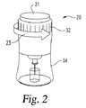
図1において、本発明の後退機構を備えた、概して20と指定される自動注射装置の第1の実施形態による斜視図が示される。図2〜図4では、装置20は簡易な針付き注射器と共に概略的に示されており、使用中の針カバーは収縮し、注射中は貫通されて図示されていない。図2では、装置20は、矢印23で示すように安全スリーブ32をハウジング本体34を中心に非係止角度位置まで回転させることによって解錠されている。装置の解錠後、矢印24で示すように始動ボタン21を押し込むと、装置20の針付き注射器25は自動的に下方に駆動して、注射器25の注射針27が装置ハウジングの下端を超えて突出し、図3に示すようにユーザを貫通する。次いで、装置は前進して、自動的に、すなわちユーザの追加動作なしに針27を通じて注射器25内の薬剤を注射する。その後、注射器は矢印29で示すように自動的に退避して、針27は図4に示すようにハウジング内に戻る。装置20内の本発明の後退機構は、針付き注射器が退避する前に薬剤内容物が適切に送達されるように確保する動作の手助けをする。後退機構は、注射器および他の装置部品における軸方向耐性を補償する手段としても有効である。 In FIG. 1, a perspective view according to a first embodiment of an automatic injection device, generally designated 20, with a retracting mechanism of the present invention is shown. In FIGS. 2-4, the
本発明の後退機構は本願に記載の装置20において有益に適用されるように示されているが、このような用途は単なる例であり、限定することを意図していない。本発明の後退機構は、恩恵が望まれる、構造の異なる多数の自動注射装置でも使用することができる。 Although the retracting mechanism of the present invention has been shown to be beneficially applied in the
図1〜図5を参照すると、装置20は、装置の作業部品が動作可能に配置される外側ハウジング30を含む。ハウジングの上端または遠位端から、ボタン21が軸方向に突出する。安全スリーブ32が回転方向に配向してボタン21を解錠し、その後、ユーザまたはユーザを助ける人がボタンを押すと、押されたボタン21によって係止リング140が図5に示すようにハウジング内で回転し、装置20の自動動作機能を始動または開始するようにプランジャ要素230を解放する。安全スリーブ32と装置の始動アセンブリは、出願第61/782929号として2013年3月14日に米国特許商標庁に提出された仮特許出願と、本願と同日に本件と同じ発明者によって受領庁である米国特許商標庁に提出された国際特許出願「自動注射装置用始動アセンブリ」とにさらに説明されており、両出願の開示全文を引用により本願に組み込む。 With reference to FIGS. 1-5, the
本願で使用される際、遠位と近位は、装置が使用のために方向付けられる際に注射部位に対する軸方向の位置を指し、たとえば、ハウジングの近位端は、上記注射部位に最も近いハウジング端を指す。 As used herein, distal and proximal refer to an axial position relative to the injection site when the device is oriented for use, for example, the proximal end of the housing is closest to the injection site Refers to the housing end.
ハウジング30の軸方向高さは、安全スリーブ32、本体34、ベースプレート35によって形成される。本体34は図6A〜図6Dにも示す。本体34はベース部37と包囲スリーブ部38とによる2つの部分の成形工程から形成される。ベース部37は注射器の内容物が見えるように透明プラスチック材料から成り、スリーブ部38は不透明プラスチック材料から成る。スリーブ部38の上方で、ベース部37の概して41と指定される上領域はディスク部42を含み、安全スリーブ32とボタン21を搭載するように構成される。本体34の放射方向に窪んだ下領域43は中央開口を画定し、雄ネジ45が設けられる。 The axial height of the
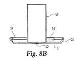
さらに図8Aおよび8Bに示すハウジングベースプレート35は、ベース部37と同じ透明材料から成る。ベースプレート35の縁部52は内周部54に沿って通り、ネジ45と係合してベースプレート35を本体34に固着させる。ベースプレート35と本体34間におけるこの確実な固定戻り止めという特徴もまた、ベースプレートが本体から抜けないことを確実にするために提供されうる。使用中に注射器針がハウジングの内外を行き来するために通る、ベースプレート35のディスク状ベース57の小さな中央孔55は、ベース57から遠位方向に延びる管部60によって環状に形成される。 Further, the
ハウジングは、本体34の中心でハウジングディスク部42から垂れ下がる図5のロッド状部分またはシャフト62によって形成される中央内側部をさらに含む。製造と組付を簡易化するため、シャフト62は別途形成されてから、図示する固定具64などで、ハウジング本体34に対して常に回転可能に軸方向に固定される。 The housing further includes a central inner portion formed by the rod-like portion or
ハウジングシャフト62は、図12A〜図12Eにさらに示す、概して70と指定されるフォロアまたは後退要素を支持する。後退要素70は1つの剛体片として形成され、開放中心76へ放射方向内側に延びる一対の対向リブまたはキー74を有する中央カラー72を含む。キー74は、カラー72の軸高全体にわたって延びる。2つのタブまたは耳部78は、カラー遠位端のカラー72の直径方向対向部から放射方向外側に突出する。リング状減衰フィン80はカラー72と同心である。フィン80は、フィン80の近位端とカラー72の中央軸領域間を延びてまたがるフランジ82によってカラー72に接続される。単独の連続フィンが設けられているが、別の実施形態では異なる形状または数のフィンと置き換えることができる。 The
2つの穴84が、フランジ82を貫通して相互に180度離れて設けられ、プランジャ要素230のキー264の上端を収容する。フィン80を通る2つの開口86は、タブ78の放射方向外側に直接設けられ、穴84間に角度を成して中心に配置される。開口86はタブ78の成型用に製造中に使用され、減衰流体をフィン80の放射方向対向側81、83に移動させるのに供する。 Two
一対の脚部90はフランジ82から近位方向に延びる。脚部90は斜め方向に湾曲して、カラー72下方の円筒状中空部91を部分的に画定する。各脚部90の斜め側面92は頑丈にするために厚く形成され、他方の脚部90の対向側面から斜めに間隔をおいて配置され、直径方向に対向し、軸方向に延びる開口94を設ける。 A pair of
開口94はプランジャ要素キー264用のキー溝としての役割を果たし、図示する実施形態ではキー係合が使用されて、フォロア70を回転可能にハウジングシャフト62に固定させることで、プランジャ要素230が始動後に軸方向へ十分な距離を移動するまでフォロアが他の位置に移動するのを防止し、他の位置では注射器が既に退避している。別の実施形態では、フォロアはプランジャ要素に固定される必要はなく、それ以外の方法でハウジング内の軌道に沿って移動するのを防止することができる。移動の防止は、軸方向に移動するプランジャ要素によっては行われない。たとえば、フォロアは、ハウジング、または掛け金や締め金などを介してシャトルなどのハウジングと回転可能に固定される部分に直接接続することができる、あるいはハウジングに対して回転可能に固定されるが軸方向には摺動可能である係止部材によって移動を阻止することができる。プランジャ要素が近位方向に移動すると、フォロアの掛け金または締め金を外す、あるいはフォロアを阻止する位置から係止部材を外に出すため、フォロアは自由にハウジングの軌道を移動する。このような別の実施形態は国際公開第WO2011/109205号および第WO2008/112472号を参照して一層理解され、同出願は引用により全文を本願に組み込む。 The
ハウジングシャフト62および後退要素70は、シャフト62に対する後退要素70の軸方向および回転方向の移動を誘導するように補完的に設計される。このため、図13A〜図13Cを参照すると、シャフト62は、軸方向に延びるチャンネル106によって接続される一対の凹部またはキー溝領域102と一対の凹部またはキー溝領域104とを有する略円筒状本体100を含み、すべての領域がキー74を密接に収容する。チャンネル106によって接続される領域102および104は、軸方向に細長いキー74用の軌道またはキー溝を形成する。上記のキー溝は1つのみ必要であるが、2つの斜めに間隔をおいたキー溝はこれらの部品のバランスを取る。1セットの凹領域102、104とチャンネル106が図13Bおよび13Cに示されているが、ディスク部132に対する以外に図13Bおよび13Cに示す側と反対側のシャフト62も同様であると理解される。各凹領域102はその領域の角度範囲全体に延びる下側肩部110と、チャンネル106がその領域に対して開放される範囲以外の全角度範囲を延びる上側肩部112と、肩部110および112にまたがり軸方向に延びる肩部114と、チャンネル106につながる端肩部116とを含む。各凹領域104は、チャンネル122以外の領域の全角度範囲に延びる上側肩部120と、チャンネル106がその領域に対して開放される範囲以外の全角度範囲に延びる下側肩部124と、チャンネル106から連続する端肩部126と、下側肩部124からチャンネル122まで軸方向に延びる上側肩部128とを含む。図示される各凹領域102はフォロア70を厳密に回転運動させるように構成されるが、いずれも軸方向成分の運動も生成するように構成することができ、つまり、フォロアは凹領域102を移動する間、回転方向にも軸方向にも移動する。 The
各上側肩部120には、角度範囲の中間部に沿って図示しない切欠きが設けられ、切欠きは組付ステップ中にバネ式フォロアを保持する留め具としての役割を果たす。 Each
凹領域102と軸方向チャンネル106によって形成される軌道は、軌道内に正方形の屈曲を有効に生成する。フォロアの移動中、凹領域102に沿って移動する各キー74が各自の軌道内の正方形の屈曲の位置に達すると、フォロアにおける減衰され緩やかにされた回転が終了し、キー74がチャンネル106に沿って凹領域102へと移動するにつれて、フォロア70における減衰されない迅速な移動が生じる。この迅速な移動はほぼ同時にフォロア退避ももたらすことによって、注射器の退避がユーザにとって視覚的にも聴覚的にも触覚的にも明らかになる。The trajectory formed by the
別の実施形態では、フォロアが装置使用前の回転方向に係止された位置から、さらに移動して係止される前に注射器を退避させる位置まで移動する際、フォロアを誘導するため、フォロアの漸進的な螺旋状のスイープ長の全部または一部に沿って軌道を形成することができる。 In another embodiment, in order to guide the follower when moving the follower from a position locked in the rotational direction prior to use of the device to a position where the syringe is retracted before being moved and locked, Trajectories can be formed along all or part of the gradual spiral sweep length.
凹領域102の近位に位置するシャフト62の溝部130はディスク部132を終端とし、装置組付の際に使用される突出部135が近位方向に拡張する。ディスク部132は軸方向に配向した開口134を含み、付勢部材150の軸方向に突出する近位端または先端152が該開口に挿入される。 The
図14に最も良く示される付勢部材150は、シャフト62に対して回転方向ならびに軸方向にフォロア70を付勢する機能を果たす。付勢部材150は螺旋コイルワイヤ154で形成される円筒状バネとして示す。バネ150は、利用可能な空間で適切な捻り力と軸方向力を提供するように選択され、この選択は所要の後退などの装置の動作や、減衰化合物、フォロア、シャトル構造などの協働部品の設計に依存する。二重の機能を果たす金属またはプラスチック屈曲部などのその他の設計の付勢部材を、単独の金属コイルバネに置き変えることもできる。別の実施形態では、部品数は増大するが、単独の付勢部材150を2つ以上の付勢部材と置き換えて軸方向および回転方向の付勢機能を提供することができる、あるいは追加片またはドライバと連結される軸バネと置き換えてカムまたはネジ面を介して捻り予荷重を提供することができる。 The urging
バネ150の内側開口156がシャフト62を自由に収容する一方、バネ150の外径がフォロア70の円筒状中空部91に自由に嵌合する。バネ150の軸方向に延びる遠位端158は、カラー72の下側に形成されるブラインドポケット(図示せず)に挿入される。バネ150の対向端コイルは、カラー72の底面とシャフトディスク部132の遠位面とに作用する。バネ150は対称であるため端部158と152は互換可能である。 The
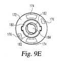
概して170と指定されるシャトル部材は、装置ハウジング30内の後退部材70によって軸方向に保持される。さらに図9A〜図9Eに示すシャトル部材170はシャトルクリップ要素216と協働して、注射器退避用のシャトルを形成する。シャトル部材170は一体成形され、プランジャ要素230を収容する一対の直径方向に対向して配置された弧状スロット174と、装置の製造組付の際に使用される一対の直径方向に対向して配置された開口176とを含む環状プレート部172を含む。プレート部172の中心には、カラー180の遠位面から近位方向に窪んだ中央部182を囲む直立カラー180が設けられる。中央部182は、製造組付中に挿入されるフォロアカラー72とタブ78の遠位端を収容する形状のキー係合する開口184を画定する。この組付中、挿入されたカラー72が回転すると、中央部182がカラータブ78と全域フランジ82間に捕捉されるため、シャトル部材170が装置の動作を通じてフォロア70に軸方向に固定される。一対の直径方向に対向するタブ188はカラー180から放射方向外側に突出し、シャトル部材170に対して軸方向に係止リング140を位置決めする役割を果たす。 A shuttle member, generally designated 170, is held axially by a retracting
カラー180のU字状下部190は環状中空部またはポケット192を画定し、フォロア70がシャトル部材170に対して回転する際に減衰流体に支持面を提供する。 The U-shaped
例えば、ナイ・ルーブリカンツ社からナイフルオロカーボンゲル880として入手可能な、テフロンで濃くされたシリコーングリースのような、図5において195として示される減衰化合物または流体は、環状ポケット192を満たす。フォロアフィン80が中空部192に嵌合するため、減衰化合物195がフィンの放射方向内外両方に配置される結果、フォロアフィン80がカラー下側190に対して回転しようとするとき、粘性減衰流体が動作中にこの回転に対抗する抵抗力を提供して、減衰または後退作用をもたらす。異なる特性を有するその他の化合物も当業者によって選択することができる。 For example, a dampening compound or fluid shown as 195 in FIG. 5, such as a Teflon thickened silicone grease available from Nai Lubricants as Nyfluorocarbon Gel 880 fills the
さらに、別の実施形態では、シャトル部材およびフォロア上に、流体を充填したポケットとそこに挿入されるフィンを配置することは、それぞれフォロアとシャトル部材上への配置に切り換えることができる。 Furthermore, in another embodiment, the placement of the fluid-filled pocket and the fins inserted therein on the shuttle member and follower can be switched to placement on the follower and shuttle member, respectively.
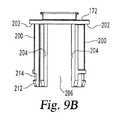
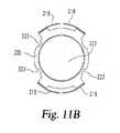
シャトル部材170は、放射方向に湾曲し、環状プレート部172から近位方向に延びる2つの脚部200をさらに含む。脚部200はプレート部172の放射方向外周部から間隔をおいて配置されるため、プレート部172の張出領域202は、プランジャ付勢バネ205の遠位端が直接接する環状面を提供する。一対の直径方向に対向する懸架フック(図示せず)をプレート部172の放射方向外周部に設けて、バネ205がシャトル部材170の中心にとどまるように確保することができる。各脚部200の軸方向に延びる斜めの側面204は他方の脚部200の対向側面から斜めに間隔をおいて配置され、軸方向に延び、直径方向に対向する開口206を形成し、その開口内で嵌合プランジャ要素脚部232はシャトル部材170に対してプランジャ要素230を回転可能に固定する。脚部200は放射方向に湾曲し、円筒状中空部203を部分的に画定する。脚部200の内側放射面207は、注射器がシャトル部材170内で上方に移動するのを防止する止め部としての役割を果たす、縦方向に延びるリブ209を含む。 The
脚部200の放射方向外周部212の下領域は、図11Aおよび11Bにさらに示すように、概して216と指定されるクリップ要素の弾性フランジ218を収容する凹状214である。クリップ要素216は単独のステンレス鋼片から成る。フランジ218は脚部200を弾性的に捕捉してクリップ要素216をシャトル部材170に固定するため両者は一体部品のように作用する。フランジ218は、中央開口222を有するリング状ベース220まで延びる。開口222は、遠位フランジ354は格納しないが、注射器筒部352は格納するような寸法に設定される。リング状ベース220は注射器フランジ354と係合するような寸法に設定され、管部60の頂部を常に軸方向に空けておくように設計される。ベース220の切欠き223は、後述するようにスリーブアーム318の通過を許容する。 The lower region of the radially
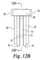
使用中のプランジャ要素はハウジング30内で軸方向に変位して、図7A〜図7Eにさらに示すように針挿入と薬剤送達230の両方を駆動する。プランジャ要素230は、脚部の近位端で外方に向いたフランジ端236を有する、軸方向に延びる脚部232を含む。プレート部248の上方の脚部232の上領域240は、シャトルプレート部172のスロット174に挿入されるような寸法と形状に設定される。上領域240は、係止リング140の補完部分を係合させるカム面244を含む。装置20の始動アセンブリがユーザによって始動されて係止リング部をカム面244から分離させるまで、プランジャ要素230は有効にラッチされ(latched)て、圧縮バネ205の付勢力下で軸方向近位に移動することを防止される。 The plunger element in use is axially displaced within the
プランジャ要素230は、脚部232にまたがる中央プレート部248も含む。部分的に閉鎖した下端252を有する円筒管250は、プランジャ脚部232間でプレート部248から垂れ下がる。下端252は装置の注射器350の封止ピストンまたはプランジャ356に直接係合する。管250は、注射器350の筒部352に挿入できるような横断面の寸法に設定される。管250の放射方向外周部と脚部232の放射方向周部間の放射方向間隙254は、プランジャ要素管250が注射器筒部352に挿入されると、上側範囲、図示されるケースでは、フランジ354と注射器350の隣接する筒部352を収容する寸法に設定される。 The
管250の内側中空部256は、装置が動作するまでフォロア脚部90を収容する寸法に設定される。端部252の4つの開口260は、最初はフォロア脚部90の延在するタブまたは拡張部95と嵌合する間隙をもたらし、該拡張部は、プランジャ要素の長い軸方向移動間にフォロア70とプランジャ要素230とを係合させておくために設けられる。内側中空部256の上領域は、一対の内側に突出するキー264によって割り込まれる。プランジャ要素230が注射中に移動してキー264が開口94の下方に降下し、プランジャ要素230に対してフォロア70が管250から外に出るまで、キー264はフォロア70の開口94に嵌合することによって、フォロア70がプランジャ要素230に対して回転するのを防止する。キー264はプレート部248の上方に拡張して、フォロア70の逃げ穴84に嵌合する。キー264はプレート部248の上方に拡張して、プランジャ要素の長い軸方向移動間にフォロア70とプランジャ要素230とを係合させておく。
The inner
プランジャ要素230は、プランジャ要素脚部232とシャトル部材脚部200との嵌合のため、常に装置20内でシャトル部材170と回転可能にキー係合される。突出リブ部280は、プランジャ脚部側面204と係合する脚部232の部分である。リブ部280は、装置組付中にスリーブアーム318を通過させるため放射方向に縮小される。 The
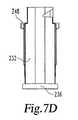
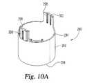
プランジャ要素230は、図10A〜図10Dにさらに示すように、概して290と指定される注射器支持部材によって軸長の大半を囲まれる。注射器支持部材290は、遠位端294から近位端296まで延びる管状本体またはスリーブ292を含む。遠位端294から突出する一対の直径方向に対向するフランジ298はそれぞれ、ベース部37の内面311に形成される縦方向に延びるリブ308を介して、ハウジング本体34に設けられた直径方向に配列されたチャンネルまたはキー溝304内で軸方向に摺動する、放射方向外側に突出するキー300を含む。
スリーブ292は、近位端296近傍の内面312に設けられるバネ支持棚310を含む。棚310は、棚310の下側に沿って斜めに間隔をおいて配置された一連のガセット314によって支持される。2つの反対に配置された対の支持アーム318は、棚310の下方の内面312から斜めに内側へ突出する。アーム318の平坦上端320はスリーブ292の中空325に間隔をおいて配置されて、注射器筒部352のフランジ354の底面と係合する。アーム318は、装置使用前、ハウジング30内の注射器350を保持するために用いられる。 The
薬剤の注射を駆動するバネ205の端コイルは棚310の頂面に接する。図5に最も良く示すように、バネ205は介在する棚310を介してプランジャ要素端236に作用する。プランジャ要素230のフランジ付き端部236はアーム318の下端325間に収まるため、プランジャ要素230は注射器支持部材290、ひいては装置ハウジング30に回転可能に固定される。このように動作可能に接続することにより、注射器支持部材290が、プランジャ要素230を有する装置20の駆動プランジャの一部として機能する。 The end coil of the
本発明の後退機構と共に使用される薬剤を充填した針付き注射器290は、概して図2〜図4に示されるような構造を有する先の尖った針の注射器など、様々な設計の注射器のいずれかであってもよい。異なる針カバーも採用することができる。図5は、針カバー380を備えた、概して350と指定される針注射器を有する装置20を示す。注射器350とカバー380は国際公開第PCT/US2012/051702号に記載される概念上類似の注射器設計を参照することで理解を深められ、同出願の開示は全文を引用により本願に組み込む。 The drug-filled
針注射器350は、遠位端に放射方向外側に延びる周縁リブまたはフランジ354を有する筒部352を含む。フランジ354下の弾性リング355は、フランジ354がシャトルベース220に及ぼす衝撃を和らげる。弾性ピストン356は筒部内部を摺動可能に封止し、薬剤内容物が筒部352の上端から出るのを防止する。筒部352の近位端のカラー部360は、貫通可能隔膜364を形成する弾性部を有するハブ362と接続し、薬剤容器の底部を封止する。
針キャリア370は両端同形のカニューレ372を保持する。針キャリア370は、窪んだ軸方向位置間でハブ362内にキー留めまたは回転可能に固定された状態で軸方向に移動可能である。針キャリア370は図5に概略的に示すが、図15〜図17にさらに示すように、ハブ362の内面に設けられるこぶと係合する戻り止めを上端部に備えた弾性アームを有する。カニューレ372の遠位端374は隔膜364を貫通し、カニューレ近位端376はカバー380とユーザを貫通する。 The
針カバー380は、装置の使用前のカニューレ372を無菌に保ち、単独の気密弾性片から成る。カバー380は、針貫通可能端部領域386を有する折畳み本体384の上端でハブ362とヒンジ領域383に装着されるリング部382を含む。 The
装置20の構造は、動作の説明を考慮に入れることでより一層理解される。該装置は当初、図5および図15に示すように構成され、バネ205は圧縮予荷重下で、シャトル部材170に対する付勢力をプランジャ230に供給する。この付勢力にもかかわらず、プランジャ230は、シャトル部材170に装着される係止リング140で有効にラッチされるため、シャトルに対して軸方向近位に移動することができない。バネ150は捻り予荷重と軸方向予荷重がそれぞれハウジング30、特にシャフト62に対してフォロア70を付勢する。この付勢にもかかわらず、フォロア70の凹領域102への嵌合の結果、キー74が上側肩部112に接するため、フォロアキー74はハウジング内で遠位に移動することができない。また、フォロア70の開口94に嵌合するキー264によるフォロア70とプランジャ要素230との係合のため、フォロアのハウジング内での回転が防止される。フォロア70と、保持されたシャトル部材170とは、フォロアキー74がシャフト肩部110に接するために近位に移動することができない。 The structure of the
注射させるため、ユーザまたはユーザを助ける人が安全スリーブ32を手動で回転させてボタン21を解錠し、装置20を注射部位に配置する。次に、ボタン21を押して始動アセンブリを動作させると、プランジャ要素250が解放されて、バネ205によってハウジング内の近位方向に変位させられる。 To make an injection, the user or someone helping the user manually rotates the
プランジャ要素250は、管250の下端252と注射器プランジャ356との係合により、プランジャ356を近位方向に駆動して、まず筒部352を下方に移動させ、カニューレ先端384をカバー領域386に貫通させ、次いでベースプレート開口55を通って延長させてユーザの肌に貫通させる。筒部352が下方に移動すると、カバー380は軸方向につぶれ始める。カニューレ先端374は、ハブ360内でまだ軸方向に保持されるため、まだ隔膜364を貫通しない。 The
プランジャ要素230がバネ205によって下方に変位され続けるにつれ、注射器筒部352が近位方向に駆動され続け、カバー380はつぶれ続ける。針キャリア370がハウジングベース57に接して、カバー領域386が間に挟まれると、針キャリアはそれ以上近位に移動できなくなる。筒部352の近位運動により、ハブ360が針キャリア370に対して下方に移動して、針先端374が隔膜364を貫通する。 As the
プランジャ要素230がさらに下方に前進すると、リング355によって緩衝された筒部フランジ354がクリップ要素ベース220に接触するまで筒部352は近位方向に移動し続ける。該接触の時点で、筒部352は近位方向に移動できなくなり、カバー380は完全につぶれ、プランジャ要素230のさらなる近位運動により、プランジャ365が筒部352内を下方に進む。管250は筒部352により深く挿入されて、注射器の内容物をカニューレ372を通じてユーザへと押し出す。 As the
プランジャ要素230がバネ205の付勢下で近位方向に移動するにつれ、キー264は開口94内をフォロア脚部90に沿って開放先端95まで降下し、該先端でフォロア70はプランジャ要素230から回転可能に解放される。通常、この解放は、プランジャの近位方向移動の終了直前に発生するように設計されるが、後退機構の後退作用の設計に応じて早めることもできる。図16は、この動作時の装置20を示す。 As the
回転可能に解放されると、フォロア70は付勢部材150の捻り予荷重によって付勢されて、シャフト62の周囲を回転し、キー74は凹領域102内で斜めに摺動する。このシャトル部材170に対するフォロアの回転により、プランジャ要素230とのキー係合を介して、ハウジング内での回転可能な固定が保持される。フォロアフィン80とシャフトカラー180間の粘性減衰化合物195は、このフォロアの回転を減衰させる、あるいはフォロアの回転に対する抵抗を提供し、この抵抗の結果、後述するようにフォロアが遠位方向に変位する前に時間が経過する。この期間に針先端376を通って注射器から適切に残りの薬剤を放出することができる。When released in a rotatable manner, the
バネ150によって駆動されるシャフト62周囲でのフォロア70の回転は、フォロアキー74が端肩部116に接して、そこでキー74がチャンネル106に揃うまで継続する。そのときまでに、プランジャ要素230は近位移動を完了して注射器プランジャ356を注射器筒部112へと完全に移動させ、適切な投与量を放出している。バネ150による軸方向力下で、フォロア70はハウジング30内で遠位方向に駆動されるため、キー74は上側肩部120に接触するまでチャンネル106を通って凹領域104まで摺動する。同時に、このフォロア70の遠位運動により、シャトル部材170とシャトルクリップ要素216も同じく遠位方向に移動する。クリップ要素216がそのように移動し、クリップベース220とフランジ354の下側が係合すると、注射器350は、注射針372の近位376をハウジング30内の保護された位置に退避させるようにシャトルによって遠位方向に搬送される。 The rotation of the
針の退避後、さらにフォロアが回転し、退避した針を係止する。具体的には、キー74が肩部120に接触すると、キー74が凹領域104に配置される。まだ残っている付勢部材150の捻り予荷重により、フォロア70はシャフト62の周囲で同じ角度方向に回転を再開し、キー74は凹領域104で斜めに摺動する。キー74が止め肩部128に接すると、フォロアの回転が止まる。上側肩部120が上述したようにフォロア捕捉機能を提供するため切欠きを有する場合、キー74が切欠きに滑り込んだときにフォロアの回転が止まる。キー74はチャンネル122には延びず、そのチャンネルはフォロア70のシャフト62への組付中に使用され、シャフト62のハウジングディスク部42への組付中、固定具64はチャンネル122をキー74まで有効に通さなくする。フォロア70、ひいてはシャトル部材170を含むシャトルがキー74による肩部124の接触係合のために近位方向に移動できないため、針付き注射器350は退避位置で係止される。この時点で、装置20は図17に示すように構成されており、ユーザは通常通り、装置を配置、あるいはそれ以外に操作することができる。 After the needle is retracted, the follower further rotates to lock the retracted needle. Specifically, when the key 74 contacts the
本発明を好適な設計を有するものとして図示し説明したが、本発明は本開示の精神と範囲内で変更することができる。たとえば、本発明の後退機構は異なる形状の部分を有することができる、あるいは別の始動部などの異なる部品を備えた装置において使用することができる。さらに、別の実施形態では、各種部品をキー係合させる様式や、特定部品を他の部品にキー係合させる事実を変更することができる。たとえば、各種部品のキーおよびキー溝を切り換えることができる、あるいは、プランジャ要素を介してなどのようにシャトルを間接的にキー係合するのではなく、回転可能に固定されるようにシャトルを直接ハウジングとキー係合することができる。さらに、上述のプランジャ要素は注射器の前進と筒部内での注射器ピストンの前進の両方を駆動するが、係合するプランジャ要素が筒部内のピストンの前進のみを駆動する後退機構を装置において採用することができる。さらに、図示する実施形態では減衰化合物はシャトルとフォロア間に直接設けられるが、別の実施形態では、フォロアとシャトルの直接減衰機能の代わりに、またはそれに追加して、フォロアと直接ハウジング間の減衰機能を設けることができるが、この場合、ハウジングに対するフォロアの軸方向移動を遅延させることで、注射器の軸方向の退避を減速させる場合がある。したがって、本願は、一般的原則を用いて、本発明のいかなる変形、使用、または改変も本発明に含めることを目的とする。さらに、本願は、本発明が関連する技術における既知のまたは通例の慣行に属するものとして、本開示からのこのような逸脱も本発明に含めることを目的とする。 While this invention has been illustrated and described as having a preferred design, the present invention can be modified within the spirit and scope of this disclosure. For example, the retracting mechanism of the present invention can have differently shaped parts, or can be used in devices with different parts such as separate starters. Furthermore, in another embodiment, the manner in which various parts are key-engaged and the fact that a specific part is key-engaged with another part can be changed. For example, the keys and keyways of various parts can be switched, or the shuttle can be directly fixed so that it can be rotatably fixed, rather than indirectly keyed, such as via a plunger element. Key-engaged with the housing. Furthermore, the above-described plunger element drives both the advancement of the syringe and the advancement of the syringe piston within the barrel, but the engaging plunger element employs a retraction mechanism in the device that drives only the advancement of the piston within the barrel. Can do. Further, in the illustrated embodiment, the damping compound is provided directly between the shuttle and the follower, but in another embodiment, an attenuation between the follower and the direct housing is provided instead of or in addition to the direct attenuation function of the follower and shuttle. A function can be provided, but in this case, the axial retraction of the syringe may be slowed by delaying the axial movement of the follower relative to the housing. This application is therefore intended to cover any variations, uses, or modifications of the invention using its general principles. Further, this application is intended to cover such departures from the present disclosure as they belong to known or customary practices in the technology to which the invention pertains.
Claims (25)
Translated fromJapaneseハウジングに対して回転可能に固定され、退避のために注射器と係合するシャトルと、
第1の方向と反対の方向に前記シャトルを変位させるフォロアであって、ハウジングの第1の位置からハウジングの第2の位置までの移動のためにハウジングとキー係合し、前記第2の位置が第1の方向と反対方向に前記第1の位置から軸方向に間隔をおくとともに、前記第1の位置から回転方向に間隔をおくフォロアと、
前記フォロアの表面と、前記シャトルおよびハウジングの少なくとも一方の表面間で、前記フォロアが前記第1の位置から前記第2の位置に向かって移動するとき、前記フォロアの回転を減衰する減衰化合物と、
前記フォロアを前記第1の位置から前記第2の位置へ推進する力を提供する少なくとも1つの付勢部材と、
筒部内のピストンを駆動して注射のために薬剤を注射針へ通す被付勢プランジャ要素であって、第1の箇所から第2の箇所へハウジング内の第1の方向に付勢され、ハウジングに対して回転可能に固定されるプランジャ要素と、
を備える後退機構であって、
前記プランジャ要素が前記第1の箇所に位置するとき、前記フォロアが前記第1の位置から前記第2の位置に向かって移動するのを防止され、前記プランジャ要素が前記第1の箇所から前記第2の箇所に移動すると、前記フォロアが前記第1の位置から前記第2の位置に向かって自由に移動して、前記少なくとも1つの付勢部材が前記フォロアを前記第1の位置から前記第2の位置へ変位させることによって、注射後に注射針をハウジング内へ退避させるために前記シャトルを移動させる後退機構。An automatic injection device having a housing and a drug-filled syringe having a barrel, a piston, and an injection needle, wherein the device moves the syringe in a first direction relative to the housing to move the injection needle beyond the housing. Is operable to extend,
A shuttle that is rotatably fixed to the housing and engages the syringe for retraction;
A follower for displacing the shuttle in a direction opposite to a first direction, keyed with the housing for movement from a first position of the housing to a second position of the housing, wherein the second position Is spaced apart in the axial direction from the first position in a direction opposite to the first direction, and follower spaced in the rotational direction from the first position;
A damping compound that attenuates rotation of the follower when the follower moves from the first position toward the second position between the surface of the follower and at least one surface of the shuttle and the housing;
At least one biasing member that provides a force to propel the follower from the first position to the second position;
A biased plunger element for driving a piston in a cylindrical portion to pass a medicine through an injection needle for injection, wherein the plunger is biased in a first direction in the housing from a first location to a second location. A plunger element that is rotatably fixed relative to
A retracting mechanism comprising:
When the plunger element is positioned at the first location, the follower is prevented from moving from the first location toward the second location, and the plunger element is moved from the first location to the first location. When the second follower moves to the second position, the follower freely moves from the first position toward the second position, and the at least one biasing member moves the follower from the first position to the second position. A retraction mechanism for moving the shuttle to retract the injection needle into the housing after injection by displacing the position to
ハウジング内で第1の方向に注射器を退避させるシャトルと、
フォロアと、
ハウジングに対して第1の位置から軸方向および回転方向に間隔を置く第2の位置まで前記フォロアを移動させる付勢手段と、
前記第1の位置から前記第2の位置に移動すると、前記シャトルを移動させて注射器を第1の方向に退避させる前記フォロアと、
ハウジングに対する前記第1の位置から前記第2の位置への前記フォロアの移動を誘導する、前記フォロアおよびハウジング上のキー係合である誘導手段と、
注射器から薬剤を押し出すプランジャと、
前記プランジャが注射器から薬剤を押し出し始めるまで、前記フォロアが前記第1の位置から前記第2の位置に向かって回転するのを防止する手段と、
前記フォロアが前記第1の位置から前記第2の位置に向かって移動するとき、前記フォロアの回転運動を減衰する手段と、
を備える後退機構。A retraction mechanism for an automatic injection device having a housing and a syringe,
A shuttle for retracting the syringe in a first direction within the housing;
Followers,
Biasing means for moving the follower from a first position relative to the housingto a second positionspaced axially and rotationally ;
The follower that moves the shuttle to retract the syringe in a first direction when moving from the first position to the second position;
Guiding meansthat is akey engagement on the follower and the housing for guiding the movement of the follower from the first position to the second position relative to the housing;
A plunger that pushes the drug out of the syringe;
Means for preventing the follower from rotating from the first position toward the second position until the plunger begins to push drug from the syringe;
Means for dampening the rotational movement of the follower as the follower moves from the first position toward the second position;
A retracting mechanism comprising:
Applications Claiming Priority (3)
| Application Number | Priority Date | Filing Date | Title |
|---|---|---|---|
| US201361783007P | 2013-03-14 | 2013-03-14 | |
| US61/783,007 | 2013-03-14 | ||
| PCT/US2014/021485WO2014159017A1 (en) | 2013-03-14 | 2014-03-07 | Delay mechanism suitable for compact automatic injection device |
Publications (3)
| Publication Number | Publication Date |
|---|---|
| JP2016517301A JP2016517301A (en) | 2016-06-16 |
| JP2016517301A5 JP2016517301A5 (en) | 2017-01-05 |
| JP6227109B2true JP6227109B2 (en) | 2017-11-08 |
Family
ID=50349965
Family Applications (1)
| Application Number | Title | Priority Date | Filing Date |
|---|---|---|---|
| JP2016500773AActiveJP6227109B2 (en) | 2013-03-14 | 2014-03-07 | Retraction mechanism for small automatic injection device |
Country Status (13)
| Country | Link |
|---|---|
| US (1) | US9925337B2 (en) |
| EP (1) | EP2968766B1 (en) |
| JP (1) | JP6227109B2 (en) |
| KR (1) | KR20150119092A (en) |
| CN (1) | CN105025958A (en) |
| AU (1) | AU2014241449A1 (en) |
| BR (1) | BR112015020017A2 (en) |
| CA (1) | CA2899558A1 (en) |
| EA (1) | EA201591482A1 (en) |
| ES (1) | ES2927108T3 (en) |
| HK (1) | HK1212641A1 (en) |
| WO (1) | WO2014159017A1 (en) |
| ZA (1) | ZA201505514B (en) |
Families Citing this family (32)
| Publication number | Priority date | Publication date | Assignee | Title |
|---|---|---|---|---|
| US9675754B2 (en) | 2012-10-24 | 2017-06-13 | Nuance Designs, LLC | Autoinjector |
| KR20150119092A (en)* | 2013-03-14 | 2015-10-23 | 일라이 릴리 앤드 캄파니 | Delay mechanism suitable for compact automatic injection device |
| MX388536B (en)* | 2014-05-07 | 2025-03-20 | Amgen Inc | AUTO-INJECTOR WITH SHOCK-REDUCING ELEMENTS. |
| JP6618486B2 (en)* | 2015-01-27 | 2019-12-11 | テルモ株式会社 | Sensor insertion device and sensor insertion device set |
| US10758677B2 (en) | 2015-04-24 | 2020-09-01 | Shl Medical Ag | Drive mechanism |
| CN113181477B (en) | 2015-06-04 | 2023-07-14 | 麦迪麦珀医疗工程有限公司 | Cartridge insertion for drug delivery device |
| FR3036965B1 (en) | 2015-06-05 | 2021-10-01 | Aptar France Sas | AUTOINJECTOR |
| FR3036966B1 (en)* | 2015-06-05 | 2021-10-01 | Aptar France Sas | AUTOINJECTOR |
| CA3027884A1 (en)* | 2015-06-15 | 2016-12-22 | Nuance Designs Of Ct, Llc | Autoinjector |
| CH711240A2 (en)* | 2015-06-23 | 2016-12-30 | Tecpharma Licensing Ag | Auto injection device. |
| CN109152883B (en)* | 2016-05-18 | 2020-12-01 | 艾斯曲尔医疗公司 | Drug delivery mechanism for drug delivery devices |
| CN109310831B (en)* | 2016-06-02 | 2021-11-23 | 西医药服务以色列有限公司 | Three position needle retraction |
| US10549044B2 (en) | 2016-06-09 | 2020-02-04 | Becton, Dickinson And Company | Spacer assembly for drug delivery system |
| US10792432B2 (en) | 2016-06-09 | 2020-10-06 | Becton, Dickinson And Company | Drive assembly and spacer for drug delivery system |
| JP7059251B2 (en) | 2016-08-01 | 2022-04-25 | ウェスト ファーマ サービシーズ イスラエル リミテッド | A spring that prevents the door from closing halfway |
| GB201701935D0 (en) | 2017-02-06 | 2017-03-22 | Owen Mumford Ltd | Medicament delivery devices |
| EP3630226A1 (en) | 2017-05-30 | 2020-04-08 | West Pharma. Services Il, Ltd. | Modular drive train for wearable injector |
| JP7244442B2 (en) | 2017-06-08 | 2023-03-22 | ノバルティス アーゲー | Injection device and injection solution transfer system |
| JP7200134B2 (en) | 2017-06-08 | 2023-01-06 | アムジエン・インコーポレーテツド | Torque driven drug delivery device |
| EP3651833B1 (en)* | 2017-07-12 | 2023-11-22 | Fresenius Vial SAS | Pump device having a holding device for receiving a syringe |
| CN111163817B (en)* | 2017-09-21 | 2022-04-01 | 西部制药服务有限公司(以色列) | Needle insertion mechanism for syringe |
| US11452821B2 (en) | 2017-10-12 | 2022-09-27 | Eli Lilly And Company | Needle shield puller for drug delivery system |
| JP7111809B2 (en) | 2017-10-16 | 2022-08-02 | ベクトン・ディキンソン・アンド・カンパニー | Spacer assembly for drug delivery device |
| JP7402799B2 (en) | 2017-12-22 | 2023-12-21 | ウェスト ファーマ サービシーズ イスラエル リミテッド | Syringes available with different cartridge sizes |
| KR102580064B1 (en)* | 2018-02-16 | 2023-09-20 | 벡톤 디킨슨 프랑스 | Medical injection device for supporting a medical container filled with a pharmaceutical composition |
| CN108434556A (en)* | 2018-05-23 | 2018-08-24 | 苏州鹏烨医疗科技有限公司 | Injection pen |
| KR20250127186A (en)* | 2018-10-15 | 2025-08-26 | 암젠 인크 | Drug delivery device having damping mechanism |
| CA3132163A1 (en) | 2019-03-15 | 2020-09-24 | Eli Lilly And Company | Automatic injection system |
| KR102412806B1 (en)* | 2021-08-27 | 2022-06-23 | 김성우 | Apparatus for injecting liquid medicine |
| EP4426399A4 (en)* | 2021-11-01 | 2025-10-15 | Becton Dickinson Co | ALARM INDICATOR FOR A DRUG DELIVERY DEVICE |
| JP2025025364A (en)* | 2023-08-09 | 2025-02-21 | 大成化工株式会社 | Injection Device |
| KR102810349B1 (en)* | 2024-09-23 | 2025-05-19 | 장원재 | Automatic injector with drug injection dosage control function |
Family Cites Families (69)
| Publication number | Priority date | Publication date | Assignee | Title |
|---|---|---|---|---|
| FR1078911A (en) | 1949-08-17 | 1954-11-24 | Automatic hypodermic syringe and its ampoule | |
| US4561856A (en) | 1983-08-18 | 1985-12-31 | Cochran Ulrich D | Infusion pump |
| US4744786A (en) | 1986-06-17 | 1988-05-17 | Cordis Corporation | Infusion pump |
| CH684086A5 (en) | 1987-08-28 | 1994-07-15 | Ferag Ag | Transport device for printed products and using the same. |
| AU652122B2 (en) | 1989-05-04 | 1994-08-18 | Western Medical Products Pty. Limited | A syringe |
| DE69024815T2 (en) | 1989-09-18 | 1996-05-23 | Robb Pascal Patent Pty. Ltd., Alderley, Queensland | SYRINGE |
| DK0440846T3 (en) | 1990-02-07 | 1993-07-12 | Vetter & Co Apotheker | Double chamber syringe and application method |
| US5393301A (en) | 1992-10-05 | 1995-02-28 | Retrax, Inc. | Retractable syringe |
| GB9111600D0 (en) | 1991-05-30 | 1991-07-24 | Owen Mumford Ltd | Improvements relating to injection devices |
| US5167304A (en) | 1991-10-15 | 1992-12-01 | Allied-Signal Inc. | Drum brake torsion/compression strut spring |
| US5150933A (en) | 1991-10-29 | 1992-09-29 | General Motors Corporation | Latch having torsion spring leg and leaf spring leg |
| US5346480A (en) | 1992-12-14 | 1994-09-13 | Q-Med, Inc. | Syringe with retractable needle |
| US5540664A (en) | 1993-05-27 | 1996-07-30 | Washington Biotech Corporation | Reloadable automatic or manual emergency injection system |
| ES2070782B1 (en) | 1993-11-05 | 1995-12-16 | Vita Invest Sa | IMPROVEMENTS IN SELF-INJECTABLE EQUIPMENT. |
| CA2135706C (en) | 1993-11-15 | 1999-06-15 | Walter E. Cover | Retractable-needle cannula insertion set with refinements to better control leakage, retraction speed, and reuse |
| FR2715071B1 (en) | 1994-01-17 | 1996-03-01 | Aguettant Lab | Automatic drug injector. |
| US5514097A (en)* | 1994-02-14 | 1996-05-07 | Genentech, Inc. | Self administered injection pen apparatus and method |
| JP3568959B2 (en) | 1995-03-07 | 2004-09-22 | イーライ・リリー・アンド・カンパニー | Reusable dosing device |
| GB9612724D0 (en) | 1996-06-18 | 1996-08-21 | Owen Mumford Ltd | Improvements relating to injection devices |
| GB9714948D0 (en) | 1997-07-16 | 1997-09-17 | Owen Mumford Ltd | Improvements relating to injection devices |
| DE29801168U1 (en) | 1998-01-24 | 1999-08-12 | Medico Dev Investment Co | Injection device |
| GB9808408D0 (en) | 1998-04-18 | 1998-06-17 | Owen Mumford Ltd | Improvements relating to injection devices |
| DE19819409A1 (en) | 1998-04-30 | 1999-11-11 | Schering Ag | Injection device |
| DE19821933C1 (en) | 1998-05-15 | 1999-11-11 | Disetronic Licensing Ag | Device for administering an injectable product |
| SE9803662D0 (en) | 1998-10-26 | 1998-10-26 | Pharmacia & Upjohn Ab | autoinjector |
| GB9903475D0 (en) | 1999-02-17 | 1999-04-07 | Owen Mumford Ltd | Improvements relating to injection devices |
| US6368303B1 (en) | 1999-10-15 | 2002-04-09 | Becton, Dickinson And Company | Retracting needle syringe |
| US6475194B2 (en) | 2000-04-05 | 2002-11-05 | Gem Plastics, Inc. | Safety syringe |
| US6387078B1 (en) | 2000-12-21 | 2002-05-14 | Gillespie, Iii Richard D. | Automatic mixing and injecting apparatus |
| US20030105430A1 (en) | 2001-11-30 | 2003-06-05 | Elan Pharma International Limited Wil House | Automatic injector |
| GB2388033A (en) | 2002-05-02 | 2003-11-05 | Pa Consulting Services | Automatic injection device |
| DK1503816T3 (en) | 2002-05-02 | 2007-04-23 | Pa Consulting Services | injection device |
| GB2396298A (en) | 2002-12-17 | 2004-06-23 | Pa Consulting Services | Injection device and drive coupling |
| GB0211294D0 (en)* | 2002-05-17 | 2002-06-26 | Owen Mumford Ltd | Improvements relating to injection devices |
| AU2003257994A1 (en) | 2002-07-31 | 2004-02-16 | Alza Corporation | Injection device providing automatic needle retraction |
| US7699816B2 (en) | 2002-10-15 | 2010-04-20 | Tecpharma Licensing Ag | Injection device with priming stroke |
| JP4339260B2 (en) | 2002-11-25 | 2009-10-07 | テクファーマ・ライセンシング・アクチェンゲゼルシャフト | Injection device with needle protection device |
| GB2396816A (en) | 2002-12-17 | 2004-07-07 | Pa Consulting Services | Injection device |
| AU2003901382A0 (en) | 2003-03-25 | 2003-04-10 | Robert Baird Watson | Hypodermic syringe |
| GB0312852D0 (en) | 2003-06-05 | 2003-07-09 | Owen Mumford Ltd | Improvements relating to syringe firing mechanisms |
| GB0315600D0 (en) | 2003-07-04 | 2003-08-13 | Owen Mumford Ltd | Improvements relating to automatic injection devices |
| DE20311996U1 (en) | 2003-08-01 | 2003-10-16 | Hoelzle Dieter Tech Projekte | injection device |
| GB2410188B (en) | 2004-01-23 | 2006-01-25 | Medical House Plc | Injection device |
| GB2414399B (en) | 2004-05-28 | 2008-12-31 | Cilag Ag Int | Injection device |
| WO2005115514A1 (en) | 2004-05-28 | 2005-12-08 | Cilag Gmbh International | Injection device |
| GB2414404B (en) | 2004-05-28 | 2009-06-03 | Cilag Ag Int | Injection device |
| GB2414406B (en) | 2004-05-28 | 2009-03-18 | Cilag Ag Int | Injection device |
| GB2414400B (en) | 2004-05-28 | 2009-01-14 | Cilag Ag Int | Injection device |
| MX2007006974A (en) | 2004-12-09 | 2007-10-11 | West Pharm Serv Inc | Automatic injection and retraction syringe. |
| GB2425062B (en) | 2005-04-06 | 2010-07-21 | Cilag Ag Int | Injection device |
| GB2424838B (en) | 2005-04-06 | 2011-02-23 | Cilag Ag Int | Injection device (adaptable drive) |
| CN101282756A (en) | 2005-06-21 | 2008-10-08 | 伊莱利利公司 | Apparatus and method for injecting a pharmaceutical |
| US20080195056A1 (en) | 2005-06-21 | 2008-08-14 | Steven Bishop | Apparatus And Method For Injecting A Pharmaceutical |
| US7955304B2 (en) | 2005-07-15 | 2011-06-07 | Shl Group Ab | Injector |
| US20110098656A1 (en) | 2005-09-27 | 2011-04-28 | Burnell Rosie L | Auto-injection device with needle protecting cap having outer and inner sleeves |
| GB0524604D0 (en) | 2005-12-02 | 2006-01-11 | Owen Mumford Ltd | Injection method and apparatus |
| US20070173770A1 (en) | 2006-01-23 | 2007-07-26 | The Medical House Plc | Injection device |
| KR101396797B1 (en) | 2006-06-30 | 2014-05-26 | 애브비 바이오테크놀로지 리미티드 | Automatic injection device |
| DE102006042233B3 (en) | 2006-09-06 | 2008-03-06 | Tecpharma Licensing Ag | Needle guard with distal and proximal needle guard |
| JP5362591B2 (en)* | 2007-03-09 | 2013-12-11 | イーライ リリー アンド カンパニー | Delay mechanism for automatic injection equipment |
| DE102007018868A1 (en) | 2007-04-19 | 2008-10-23 | Lts Lohmann Therapie-Systeme Ag | Disposable injector with at least one towing hook and a sliding wedge gear for unlocking releasing a locking element |
| CA2711653C (en) | 2008-01-23 | 2016-07-05 | Novo Nordisk A/S | Device for injecting apportioned doses of liquid drug |
| US8048029B2 (en) | 2008-06-20 | 2011-11-01 | West Pharmaceutical Services, Inc. | Injector apparatus |
| GB2463034B (en) | 2008-08-28 | 2012-11-07 | Owen Mumford Ltd | Autoinjection devices |
| KR101366427B1 (en) | 2009-03-13 | 2014-02-24 | 일라이 릴리 앤드 캄파니 | Apparatus for injecting a pharmaceutical with automatic syringe retraction following injection |
| DK2536453T3 (en) | 2010-02-18 | 2014-11-24 | Sanofi Aventis Deutschland | autoinjector |
| ES2484266T3 (en)* | 2010-03-01 | 2014-08-11 | Eli Lilly And Company | Automatic injection device with delay mechanism including a double function thrust element |
| ES2682269T3 (en)* | 2012-10-19 | 2018-09-19 | Eli Lilly And Company | Automatic injection device with trigger set |
| KR20150119092A (en)* | 2013-03-14 | 2015-10-23 | 일라이 릴리 앤드 캄파니 | Delay mechanism suitable for compact automatic injection device |
- 2014
- 2014-03-07KRKR1020157024628Apatent/KR20150119092A/ennot_activeCeased
- 2014-03-07JPJP2016500773Apatent/JP6227109B2/enactiveActive
- 2014-03-07EAEA201591482Apatent/EA201591482A1/enunknown
- 2014-03-07ESES14712519Tpatent/ES2927108T3/enactiveActive
- 2014-03-07CACA2899558Apatent/CA2899558A1/ennot_activeAbandoned
- 2014-03-07EPEP14712519.9Apatent/EP2968766B1/enactiveActive
- 2014-03-07CNCN201480015075.5Apatent/CN105025958A/enactivePending
- 2014-03-07BRBR112015020017Apatent/BR112015020017A2/ennot_activeIP Right Cessation
- 2014-03-07AUAU2014241449Apatent/AU2014241449A1/ennot_activeAbandoned
- 2014-03-07HKHK16100628.2Apatent/HK1212641A1/enunknown
- 2014-03-07WOPCT/US2014/021485patent/WO2014159017A1/enactiveApplication Filing
- 2014-03-07USUS14/770,472patent/US9925337B2/enactiveActive
- 2015
- 2015-07-31ZAZA2015/05514Apatent/ZA201505514B/enunknown
Also Published As
| Publication number | Publication date |
|---|---|
| AU2014241449A1 (en) | 2015-08-13 |
| EA201591482A1 (en) | 2016-01-29 |
| CN105025958A (en) | 2015-11-04 |
| ES2927108T3 (en) | 2022-11-02 |
| JP2016517301A (en) | 2016-06-16 |
| WO2014159017A1 (en) | 2014-10-02 |
| ZA201505514B (en) | 2017-05-31 |
| US9925337B2 (en) | 2018-03-27 |
| CA2899558A1 (en) | 2014-10-02 |
| EP2968766A1 (en) | 2016-01-20 |
| HK1212641A1 (en) | 2016-06-17 |
| EP2968766B1 (en) | 2022-08-10 |
| KR20150119092A (en) | 2015-10-23 |
| BR112015020017A2 (en) | 2017-07-18 |
| US20160001004A1 (en) | 2016-01-07 |
Similar Documents
| Publication | Publication Date | Title |
|---|---|---|
| JP6227109B2 (en) | Retraction mechanism for small automatic injection device | |
| JP5833229B2 (en) | Low cost single use syringe | |
| JP6038976B2 (en) | Automatic injection device with delay mechanism including dual function biasing member | |
| JP6326418B2 (en) | Automatic injection device with trigger assembly | |
| JP4588072B2 (en) | Coupling for automatic injection equipment | |
| CN101563125B (en) | Needle protection device with a blocked protection position | |
| JP6667003B2 (en) | Drug injection device with automatic needle retraction after injection | |
| KR102118819B1 (en) | Dosage mechanism for drug delivery devices | |
| JP6132969B2 (en) | Trigger assembly for automatic injection device | |
| JP2010520786A (en) | Delay mechanism for automatic injection equipment | |
| CN109689131A (en) | medicament delivery device | |
| JP2008500859A (en) | Injection device | |
| JP2013529989A (en) | Injection device with needle shield | |
| RU2612844C2 (en) | Previously filled automatically retractable safe syringe | |
| JP2018519086A (en) | Drug delivery device | |
| JP6118848B2 (en) | Low cost single use syringe | |
| JP6080914B2 (en) | Low cost single use syringe | |
| JP4616835B2 (en) | Medical product injection device |
Legal Events
| Date | Code | Title | Description |
|---|---|---|---|
| A521 | Request for written amendment filed | Free format text:JAPANESE INTERMEDIATE CODE: A523 Effective date:20151006 | |
| A621 | Written request for application examination | Free format text:JAPANESE INTERMEDIATE CODE: A621 Effective date:20150911 | |
| A131 | Notification of reasons for refusal | Free format text:JAPANESE INTERMEDIATE CODE: A131 Effective date:20160628 | |
| A601 | Written request for extension of time | Free format text:JAPANESE INTERMEDIATE CODE: A601 Effective date:20160928 | |
| A524 | Written submission of copy of amendment under article 19 pct | Free format text:JAPANESE INTERMEDIATE CODE: A524 Effective date:20161117 | |
| A131 | Notification of reasons for refusal | Free format text:JAPANESE INTERMEDIATE CODE: A131 Effective date:20170110 | |
| A521 | Request for written amendment filed | Free format text:JAPANESE INTERMEDIATE CODE: A523 Effective date:20170403 | |
| TRDD | Decision of grant or rejection written | ||
| A01 | Written decision to grant a patent or to grant a registration (utility model) | Free format text:JAPANESE INTERMEDIATE CODE: A01 Effective date:20170912 | |
| A61 | First payment of annual fees (during grant procedure) | Free format text:JAPANESE INTERMEDIATE CODE: A61 Effective date:20171010 | |
| R150 | Certificate of patent or registration of utility model | Ref document number:6227109 Country of ref document:JP Free format text:JAPANESE INTERMEDIATE CODE: R150 | |
| R250 | Receipt of annual fees | Free format text:JAPANESE INTERMEDIATE CODE: R250 | |
| R250 | Receipt of annual fees | Free format text:JAPANESE INTERMEDIATE CODE: R250 | |
| R250 | Receipt of annual fees | Free format text:JAPANESE INTERMEDIATE CODE: R250 | |
| R250 | Receipt of annual fees | Free format text:JAPANESE INTERMEDIATE CODE: R250 | |
| R250 | Receipt of annual fees | Free format text:JAPANESE INTERMEDIATE CODE: R250 |