JP6224070B2 - Retainer assembly including tissue thickness compensator - Google Patents
Retainer assembly including tissue thickness compensatorDownload PDFInfo
- Publication number
- JP6224070B2 JP6224070B2JP2015503490AJP2015503490AJP6224070B2JP 6224070 B2JP6224070 B2JP 6224070B2JP 2015503490 AJP2015503490 AJP 2015503490AJP 2015503490 AJP2015503490 AJP 2015503490AJP 6224070 B2JP6224070 B2JP 6224070B2
- Authority
- JP
- Japan
- Prior art keywords
- staple
- staple cartridge
- tissue thickness
- thickness compensator
- anvil
- Prior art date
- Legal status (The legal status is an assumption and is not a legal conclusion. Google has not performed a legal analysis and makes no representation as to the accuracy of the status listed.)
- Active
Links
- 230000014759maintenance of locationEffects0.000claimsdescription502
- 238000005520cutting processMethods0.000claimsdescription158
- 230000007246mechanismEffects0.000claimsdescription127
- 239000000853adhesiveSubstances0.000claimsdescription90
- 230000001070adhesive effectEffects0.000claimsdescription90
- 238000007906compressionMethods0.000claimsdescription64
- 230000006835compressionEffects0.000claimsdescription64
- 239000003795chemical substances by applicationSubstances0.000claimsdescription40
- 210000001519tissueAnatomy0.000description1949
- 239000010410layerSubstances0.000description824
- 239000000463materialSubstances0.000description366
- 238000010304firingMethods0.000description341
- 239000011159matrix materialSubstances0.000description341
- 239000012636effectorSubstances0.000description326
- 239000003814drugSubstances0.000description144
- 239000002585baseSubstances0.000description130
- 229940079593drugDrugs0.000description118
- 229920000954PolyglycolidePolymers0.000description94
- 239000004633polyglycolic acidSubstances0.000description93
- 230000033001locomotionEffects0.000description88
- 229920000642polymerPolymers0.000description88
- 230000036961partial effectEffects0.000description78
- 238000000034methodMethods0.000description77
- 239000000203mixtureSubstances0.000description76
- 239000004632polycaprolactoneSubstances0.000description76
- 229920001610polycaprolactonePolymers0.000description76
- 229920000747poly(lactic acid)Polymers0.000description59
- 229920000117poly(dioxanone)Polymers0.000description49
- 230000008569processEffects0.000description48
- 239000000835fiberSubstances0.000description47
- 238000003780insertionMethods0.000description39
- 230000037431insertionEffects0.000description39
- 230000015572biosynthetic processEffects0.000description38
- 238000005755formation reactionMethods0.000description38
- 239000005014poly(hydroxyalkanoate)Substances0.000description37
- 239000006260foamSubstances0.000description35
- -1for exampleSubstances0.000description35
- 239000011248coating agentSubstances0.000description34
- 238000000576coating methodMethods0.000description34
- 239000012530fluidSubstances0.000description30
- 239000004627regenerated celluloseSubstances0.000description30
- 229920001432poly(L-lactide)Polymers0.000description28
- JVTAAEKCZFNVCJ-REOHCLBHSA-NL-lactic acidChemical compoundC[C@H](O)C(O)=OJVTAAEKCZFNVCJ-REOHCLBHSA-N0.000description27
- 239000000560biocompatible materialSubstances0.000description27
- 239000007800oxidant agentSubstances0.000description27
- 229920003023plasticPolymers0.000description26
- 239000004033plasticSubstances0.000description26
- 229920000903polyhydroxyalkanoatePolymers0.000description26
- 229920002463poly(p-dioxanone) polymerPolymers0.000description25
- 239000000622polydioxanoneSubstances0.000description25
- 230000001681protective effectEffects0.000description25
- 238000011068loading methodMethods0.000description24
- 230000006870functionEffects0.000description19
- 239000004626polylactic acidSubstances0.000description19
- RTAQQCXQSZGOHL-UHFFFAOYSA-NTitaniumChemical compound[Ti]RTAQQCXQSZGOHL-UHFFFAOYSA-N0.000description18
- 229940124597therapeutic agentDrugs0.000description18
- 239000010936titaniumSubstances0.000description18
- 230000008878couplingEffects0.000description17
- 238000010168coupling processMethods0.000description17
- 238000005859coupling reactionMethods0.000description17
- 230000000717retained effectEffects0.000description17
- 229910001220stainless steelInorganic materials0.000description17
- 239000010935stainless steelSubstances0.000description17
- 102000009123FibrinHuman genes0.000description15
- 108010073385FibrinProteins0.000description15
- BWGVNKXGVNDBDI-UHFFFAOYSA-NFibrin monomerChemical compoundCNC(=O)CNC(=O)CNBWGVNKXGVNDBDI-UHFFFAOYSA-N0.000description15
- 230000007423decreaseEffects0.000description15
- 229950003499fibrinDrugs0.000description15
- 238000004519manufacturing processMethods0.000description15
- 239000013543active substanceSubstances0.000description14
- 239000000017hydrogelSubstances0.000description14
- 229910052751metalInorganic materials0.000description14
- 239000002184metalSubstances0.000description14
- 238000003466weldingMethods0.000description14
- 108010035532CollagenProteins0.000description13
- 102000008186CollagenHuman genes0.000description13
- 229920001436collagenPolymers0.000description13
- 229920001577copolymerPolymers0.000description13
- 230000002439hemostatic effectEffects0.000description13
- 239000011148porous materialSubstances0.000description13
- LCSKNASZPVZHEG-UHFFFAOYSA-N3,6-dimethyl-1,4-dioxane-2,5-dione;1,4-dioxane-2,5-dioneChemical groupO=C1COC(=O)CO1.CC1OC(=O)C(C)OC1=OLCSKNASZPVZHEG-UHFFFAOYSA-N0.000description12
- 108010010803GelatinProteins0.000description12
- 229920000159gelatinPolymers0.000description12
- 239000008273gelatinSubstances0.000description12
- 235000019322gelatineNutrition0.000description12
- 235000011852gelatine dessertsNutrition0.000description12
- 239000004094surface-active agentSubstances0.000description12
- 210000004027cellAnatomy0.000description11
- 238000004891communicationMethods0.000description11
- 239000006261foam materialSubstances0.000description11
- 229920001282polysaccharidePolymers0.000description11
- 239000005017polysaccharideSubstances0.000description11
- 150000004804polysaccharidesChemical class0.000description11
- XLYOFNOQVPJJNP-UHFFFAOYSA-NwaterSubstancesOXLYOFNOQVPJJNP-UHFFFAOYSA-N0.000description11
- 102000016942ElastinHuman genes0.000description10
- 108010014258ElastinProteins0.000description10
- 102000003886GlycoproteinsHuman genes0.000description10
- 108090000288GlycoproteinsProteins0.000description10
- 102000016611ProteoglycansHuman genes0.000description10
- 108010067787ProteoglycansProteins0.000description10
- 229940030225antihemorrhagicsDrugs0.000description10
- 210000004369bloodAnatomy0.000description10
- 239000008280bloodSubstances0.000description10
- 239000002775capsuleSubstances0.000description10
- 239000002131composite materialSubstances0.000description10
- 229920002549elastinPolymers0.000description10
- 239000002874hemostatic agentSubstances0.000description10
- 239000011859microparticleSubstances0.000description10
- 239000002105nanoparticleSubstances0.000description10
- 102000004169proteins and genesHuman genes0.000description10
- 108090000623proteins and genesProteins0.000description10
- 230000008093supporting effectEffects0.000description10
- 229910052719titaniumInorganic materials0.000description10
- PAPBSGBWRJIAAV-UHFFFAOYSA-Nε-CaprolactoneChemical compoundO=C1CCCCCO1PAPBSGBWRJIAAV-UHFFFAOYSA-N0.000description10
- 238000010586diagramMethods0.000description9
- 239000007788liquidSubstances0.000description9
- 230000000149penetrating effectEffects0.000description9
- 239000000843powderSubstances0.000description9
- 230000002265preventionEffects0.000description9
- 229910001200FerrotitaniumInorganic materials0.000description8
- 239000004696Poly ether ether ketoneSubstances0.000description8
- 108090000190ThrombinProteins0.000description8
- 229920001971elastomerPolymers0.000description8
- 229920001198elastomeric copolymerPolymers0.000description8
- 229920002530polyetherether ketonePolymers0.000description8
- 230000002829reductive effectEffects0.000description8
- 229960004072thrombinDrugs0.000description8
- 238000012546transferMethods0.000description8
- RKDVKSZUMVYZHH-UHFFFAOYSA-N1,4-dioxane-2,5-dioneChemical compoundO=C1COC(=O)CO1RKDVKSZUMVYZHH-UHFFFAOYSA-N0.000description7
- 241000894006BacteriaSpecies0.000description7
- 208000011231Crohn diseaseDiseases0.000description7
- 238000005452bendingMethods0.000description7
- 238000010828elutionMethods0.000description7
- 230000001965increasing effectEffects0.000description7
- 230000001590oxidative effectEffects0.000description7
- 229920001296polysiloxanePolymers0.000description7
- 229920001059synthetic polymerPolymers0.000description7
- YFHICDDUDORKJB-UHFFFAOYSA-Ntrimethylene carbonateChemical compoundO=C1OCCCO1YFHICDDUDORKJB-UHFFFAOYSA-N0.000description7
- 230000002745absorbentEffects0.000description6
- 239000002250absorbentSubstances0.000description6
- 230000005540biological transmissionEffects0.000description6
- 239000000945fillerSubstances0.000description6
- JVTAAEKCZFNVCJ-UHFFFAOYSA-Nlactic acidChemical compoundCC(O)C(O)=OJVTAAEKCZFNVCJ-UHFFFAOYSA-N0.000description6
- 239000004310lactic acidSubstances0.000description6
- JJTUDXZGHPGLLC-UHFFFAOYSA-NlactideChemical compoundCC1OC(=O)C(C)OC1=OJJTUDXZGHPGLLC-UHFFFAOYSA-N0.000description6
- 239000002245particleSubstances0.000description6
- 230000002028prematureEffects0.000description6
- 238000003825pressingMethods0.000description6
- 230000004044responseEffects0.000description6
- 230000002441reversible effectEffects0.000description6
- 230000003068static effectEffects0.000description6
- 239000000758substrateSubstances0.000description6
- VPVXHAANQNHFSF-UHFFFAOYSA-N1,4-dioxan-2-oneChemical compoundO=C1COCCO1VPVXHAANQNHFSF-UHFFFAOYSA-N0.000description5
- XEFQLINVKFYRCS-UHFFFAOYSA-NTriclosanChemical compoundOC1=CC(Cl)=CC=C1OC1=CC=C(Cl)C=C1ClXEFQLINVKFYRCS-UHFFFAOYSA-N0.000description5
- 230000004913activationEffects0.000description5
- 239000012298atmosphereSubstances0.000description5
- QVGXLLKOCUKJST-UHFFFAOYSA-Natomic oxygenChemical compound[O]QVGXLLKOCUKJST-UHFFFAOYSA-N0.000description5
- 230000008901benefitEffects0.000description5
- 210000001124body fluidAnatomy0.000description5
- 239000010839body fluidSubstances0.000description5
- 239000013013elastic materialSubstances0.000description5
- 239000000806elastomerSubstances0.000description5
- 238000001125extrusionMethods0.000description5
- 239000000499gelSubstances0.000description5
- 238000001746injection mouldingMethods0.000description5
- KBOPZPXVLCULAV-UHFFFAOYSA-NmesalamineChemical compoundNC1=CC=C(O)C(C(O)=O)=C1KBOPZPXVLCULAV-UHFFFAOYSA-N0.000description5
- 239000001301oxygenSubstances0.000description5
- 229910052760oxygenInorganic materials0.000description5
- 238000001356surgical procedureMethods0.000description5
- 230000001225therapeutic effectEffects0.000description5
- 238000013519translationMethods0.000description5
- 229960003500triclosanDrugs0.000description5
- 239000011800void materialSubstances0.000description5
- IJGRMHOSHXDMSA-UHFFFAOYSA-NAtomic nitrogenChemical compoundN#NIJGRMHOSHXDMSA-UHFFFAOYSA-N0.000description4
- CURLTUGMZLYLDI-UHFFFAOYSA-NCarbon dioxideChemical compoundO=C=OCURLTUGMZLYLDI-UHFFFAOYSA-N0.000description4
- AOJJSUZBOXZQNB-TZSSRYMLSA-NDoxorubicinChemical compoundO([C@H]1C[C@@](O)(CC=2C(O)=C3C(=O)C=4C=CC=C(C=4C(=O)C3=C(O)C=21)OC)C(=O)CO)[C@H]1C[C@H](N)[C@H](O)[C@H](C)O1AOJJSUZBOXZQNB-TZSSRYMLSA-N0.000description4
- MHAJPDPJQMAIIY-UHFFFAOYSA-NHydrogen peroxideChemical compoundOOMHAJPDPJQMAIIY-UHFFFAOYSA-N0.000description4
- 239000002202Polyethylene glycolSubstances0.000description4
- BQCADISMDOOEFD-UHFFFAOYSA-NSilverChemical compound[Ag]BQCADISMDOOEFD-UHFFFAOYSA-N0.000description4
- FAPWRFPIFSIZLT-UHFFFAOYSA-MSodium chlorideChemical compound[Na+].[Cl-]FAPWRFPIFSIZLT-UHFFFAOYSA-M0.000description4
- 239000003242anti bacterial agentSubstances0.000description4
- 239000004599antimicrobialSubstances0.000description4
- 238000013459approachMethods0.000description4
- 230000000740bleeding effectEffects0.000description4
- 230000005611electricityEffects0.000description4
- 238000007373indentationMethods0.000description4
- 230000003993interactionEffects0.000description4
- 235000014655lactic acidNutrition0.000description4
- 210000002429large intestineAnatomy0.000description4
- 230000000670limiting effectEffects0.000description4
- 239000000314lubricantSubstances0.000description4
- 230000035515penetrationEffects0.000description4
- 239000004417polycarbonateSubstances0.000description4
- 229920000515polycarbonatePolymers0.000description4
- 229920001223polyethylene glycolPolymers0.000description4
- 229920000223polyglycerolPolymers0.000description4
- 229920002994synthetic fiberPolymers0.000description4
- KIUKXJAPPMFGSW-DNGZLQJQSA-N(2S,3S,4S,5R,6R)-6-[(2S,3R,4R,5S,6R)-3-Acetamido-2-[(2S,3S,4R,5R,6R)-6-[(2R,3R,4R,5S,6R)-3-acetamido-2,5-dihydroxy-6-(hydroxymethyl)oxan-4-yl]oxy-2-carboxy-4,5-dihydroxyoxan-3-yl]oxy-5-hydroxy-6-(hydroxymethyl)oxan-4-yl]oxy-3,4,5-trihydroxyoxane-2-carboxylic acidChemical compoundCC(=O)N[C@H]1[C@H](O)O[C@H](CO)[C@@H](O)[C@@H]1O[C@H]1[C@H](O)[C@@H](O)[C@H](O[C@H]2[C@@H]([C@@H](O[C@H]3[C@@H]([C@@H](O)[C@H](O)[C@H](O3)C(O)=O)O)[C@H](O)[C@@H](CO)O2)NC(C)=O)[C@@H](C(O)=O)O1KIUKXJAPPMFGSW-DNGZLQJQSA-N0.000description3
- MZOFCQQQCNRIBI-VMXHOPILSA-N(3s)-4-[[(2s)-1-[[(2s)-1-[[(1s)-1-carboxy-2-hydroxyethyl]amino]-4-methyl-1-oxopentan-2-yl]amino]-5-(diaminomethylideneamino)-1-oxopentan-2-yl]amino]-3-[[2-[[(2s)-2,6-diaminohexanoyl]amino]acetyl]amino]-4-oxobutanoic acidChemical compoundOC[C@@H](C(O)=O)NC(=O)[C@H](CC(C)C)NC(=O)[C@H](CCCN=C(N)N)NC(=O)[C@H](CC(O)=O)NC(=O)CNC(=O)[C@@H](N)CCCCNMZOFCQQQCNRIBI-VMXHOPILSA-N0.000description3
- JJTUDXZGHPGLLC-IMJSIDKUSA-N4511-42-6Chemical compoundC[C@@H]1OC(=O)[C@H](C)OC1=OJJTUDXZGHPGLLC-IMJSIDKUSA-N0.000description3
- OUYCCCASQSFEME-QMMMGPOBSA-NL-tyrosineChemical compoundOC(=O)[C@@H](N)CC1=CC=C(O)C=C1OUYCCCASQSFEME-QMMMGPOBSA-N0.000description3
- 102100022365NAD(P)H dehydrogenase [quinone] 1Human genes0.000description3
- 239000004743PolypropyleneSubstances0.000description3
- 108060008682Tumor Necrosis FactorProteins0.000description3
- 102000000852Tumor Necrosis Factor-alphaHuman genes0.000description3
- 239000002253acidSubstances0.000description3
- 108010066657azoreductaseProteins0.000description3
- 230000008859changeEffects0.000description3
- 238000004140cleaningMethods0.000description3
- 239000004020conductorSubstances0.000description3
- 238000013270controlled releaseMethods0.000description3
- 239000013536elastomeric materialSubstances0.000description3
- 230000009477glass transitionEffects0.000description3
- 230000023597hemostasisEffects0.000description3
- 229920002674hyaluronanPolymers0.000description3
- 229960003160hyaluronic acidDrugs0.000description3
- WQYVRQLZKVEZGA-UHFFFAOYSA-NhypochloriteChemical compoundCl[O-]WQYVRQLZKVEZGA-UHFFFAOYSA-N0.000description3
- 239000007943implantSubstances0.000description3
- 229960000598infliximabDrugs0.000description3
- 229960004963mesalazineDrugs0.000description3
- 239000007769metal materialSubstances0.000description3
- 238000000465mouldingMethods0.000description3
- 229920000728polyesterPolymers0.000description3
- 229920000139polyethylene terephthalatePolymers0.000description3
- 239000005020polyethylene terephthalateSubstances0.000description3
- 229920001155polypropylenePolymers0.000description3
- 229920002635polyurethanePolymers0.000description3
- 239000004814polyurethaneSubstances0.000description3
- 229940002612prodrugDrugs0.000description3
- 239000000651prodrugSubstances0.000description3
- 230000005855radiationEffects0.000description3
- 239000005060rubberSubstances0.000description3
- 239000000565sealantSubstances0.000description3
- 238000007789sealingMethods0.000description3
- 229940116351sebacateDrugs0.000description3
- CXMXRPHRNRROMY-UHFFFAOYSA-Lsebacate(2-)Chemical compound[O-]C(=O)CCCCCCCCC([O-])=OCXMXRPHRNRROMY-UHFFFAOYSA-L0.000description3
- 239000002356single layerSubstances0.000description3
- 239000011780sodium chlorideSubstances0.000description3
- MWNQXXOSWHCCOZ-UHFFFAOYSA-Lsodium;oxido carbonateChemical compound[Na+].[O-]OC([O-])=OMWNQXXOSWHCCOZ-UHFFFAOYSA-L0.000description3
- 208000024891symptomDiseases0.000description3
- 210000003813thumbAnatomy0.000description3
- OUYCCCASQSFEME-UHFFFAOYSA-NtyrosineNatural productsOC(=O)C(N)CC1=CC=C(O)C=C1OUYCCCASQSFEME-UHFFFAOYSA-N0.000description3
- CIWBSHSKHKDKBQ-JLAZNSOCSA-NAscorbic acidNatural productsOC[C@H](O)[C@H]1OC(=O)C(O)=C1OCIWBSHSKHKDKBQ-JLAZNSOCSA-N0.000description2
- 0C1CC*CC1Chemical compoundC1CC*CC10.000description2
- OYPRJOBELJOOCE-UHFFFAOYSA-NCalciumChemical compound[Ca]OYPRJOBELJOOCE-UHFFFAOYSA-N0.000description2
- 229920002134Carboxymethyl cellulosePolymers0.000description2
- 239000001856Ethyl celluloseSubstances0.000description2
- ZZSNKZQZMQGXPY-UHFFFAOYSA-NEthyl celluloseChemical compoundCCOCC1OC(OC)C(OCC)C(OCC)C1OC1C(O)C(O)C(OC)C(CO)O1ZZSNKZQZMQGXPY-UHFFFAOYSA-N0.000description2
- 239000004812Fluorinated ethylene propyleneSubstances0.000description2
- 229930182566GentamicinNatural products0.000description2
- CEAZRRDELHUEMR-URQXQFDESA-NGentamicinChemical compoundO1[C@H](C(C)NC)CC[C@@H](N)[C@H]1O[C@H]1[C@H](O)[C@@H](O[C@@H]2[C@@H]([C@@H](NC)[C@@](C)(O)CO2)O)[C@H](N)C[C@@H]1NCEAZRRDELHUEMR-URQXQFDESA-N0.000description2
- PEDCQBHIVMGVHV-UHFFFAOYSA-NGlycerineChemical compoundOCC(O)COPEDCQBHIVMGVHV-UHFFFAOYSA-N0.000description2
- 229930192392MitomycinNatural products0.000description2
- NWIBSHFKIJFRCO-WUDYKRTCSA-NMytomycinChemical compoundC1N2C(C(C(C)=C(N)C3=O)=O)=C3[C@@H](COC(N)=O)[C@@]2(OC)[C@@H]2[C@H]1N2NWIBSHFKIJFRCO-WUDYKRTCSA-N0.000description2
- 239000004677NylonSubstances0.000description2
- 229920002732PolyanhydridePolymers0.000description2
- 239000004698PolyethyleneSubstances0.000description2
- 229920001710PolyorthoesterPolymers0.000description2
- WCUXLLCKKVVCTQ-UHFFFAOYSA-MPotassium chlorideChemical compound[Cl-].[K+]WCUXLLCKKVVCTQ-UHFFFAOYSA-M0.000description2
- 229910000831SteelInorganic materials0.000description2
- 108010022394Threonine synthaseProteins0.000description2
- 229920004738ULTEM®Polymers0.000description2
- 238000010521absorption reactionMethods0.000description2
- 230000009471actionEffects0.000description2
- 230000003213activating effectEffects0.000description2
- 239000002313adhesive filmSubstances0.000description2
- 229940009456adriamycinDrugs0.000description2
- 229940088710antibiotic agentDrugs0.000description2
- 239000002246antineoplastic agentSubstances0.000description2
- 229960005070ascorbic acidDrugs0.000description2
- 235000010323ascorbic acidNutrition0.000description2
- 239000011668ascorbic acidSubstances0.000description2
- 230000003115biocidal effectEffects0.000description2
- 229920000249biocompatible polymerPolymers0.000description2
- 238000006065biodegradation reactionMethods0.000description2
- 230000004071biological effectEffects0.000description2
- 239000011575calciumSubstances0.000description2
- 229910052791calciumInorganic materials0.000description2
- 239000001569carbon dioxideSubstances0.000description2
- 229910002092carbon dioxideInorganic materials0.000description2
- 239000001768carboxy methyl celluloseSubstances0.000description2
- 235000010948carboxy methyl celluloseNutrition0.000description2
- 239000008112carboxymethyl-celluloseSubstances0.000description2
- 229910010293ceramic materialInorganic materials0.000description2
- DQLATGHUWYMOKM-UHFFFAOYSA-LcisplatinChemical compoundN[Pt](N)(Cl)ClDQLATGHUWYMOKM-UHFFFAOYSA-L0.000description2
- 229960004316cisplatinDrugs0.000description2
- 238000011443conventional therapyMethods0.000description2
- 230000001186cumulative effectEffects0.000description2
- 230000000994depressogenic effectEffects0.000description2
- 102000004419dihydrofolate reductaseHuman genes0.000description2
- 229960003722doxycyclineDrugs0.000description2
- XQTWDDCIUJNLTR-CVHRZJFOSA-Ndoxycycline monohydrateChemical compoundO.O=C1C2=C(O)C=CC=C2[C@H](C)[C@@H]2C1=C(O)[C@]1(O)C(=O)C(C(N)=O)=C(O)[C@@H](N(C)C)[C@@H]1[C@H]2OXQTWDDCIUJNLTR-CVHRZJFOSA-N0.000description2
- 239000008393encapsulating agentSubstances0.000description2
- 235000019325ethyl celluloseNutrition0.000description2
- 229920001249ethyl cellulosePolymers0.000description2
- 229920000295expanded polytetrafluoroethylenePolymers0.000description2
- 239000004744fabricSubstances0.000description2
- 239000002657fibrous materialSubstances0.000description2
- 238000009472formulationMethods0.000description2
- 239000007789gasSubstances0.000description2
- 210000001035gastrointestinal tractAnatomy0.000description2
- 229960002518gentamicinDrugs0.000description2
- 230000035876healingEffects0.000description2
- JYGXADMDTFJGBT-VWUMJDOOSA-NhydrocortisoneChemical compoundO=C1CC[C@]2(C)[C@H]3[C@@H](O)C[C@](C)([C@@](CC4)(O)C(=O)CO)[C@@H]4[C@@H]3CCC2=C1JYGXADMDTFJGBT-VWUMJDOOSA-N0.000description2
- 230000001976improved effectEffects0.000description2
- 238000002347injectionMethods0.000description2
- 239000007924injectionSubstances0.000description2
- 230000001788irregularEffects0.000description2
- TYQCGQRIZGCHNB-JLAZNSOCSA-Nl-ascorbic acidChemical compoundOC[C@H](O)[C@H]1OC(O)=C(O)C1=OTYQCGQRIZGCHNB-JLAZNSOCSA-N0.000description2
- 230000007774longtermEffects0.000description2
- 210000004379membraneAnatomy0.000description2
- 239000012528membraneSubstances0.000description2
- GLVAUDGFNGKCSF-UHFFFAOYSA-NmercaptopurineChemical compoundS=C1NC=NC2=C1NC=N2GLVAUDGFNGKCSF-UHFFFAOYSA-N0.000description2
- 150000002739metalsChemical class0.000description2
- 229960004857mitomycinDrugs0.000description2
- 238000012986modificationMethods0.000description2
- 230000004048modificationEffects0.000description2
- 229910052757nitrogenInorganic materials0.000description2
- 229920001778nylonPolymers0.000description2
- 230000037361pathwayEffects0.000description2
- 229920009441perflouroethylene propylenePolymers0.000description2
- 229920001308poly(aminoacid)Polymers0.000description2
- 229920003229poly(methyl methacrylate)Polymers0.000description2
- 239000002745poly(ortho ester)Substances0.000description2
- 229920000573polyethylenePolymers0.000description2
- 229920001195polyisoprenePolymers0.000description2
- 239000004926polymethyl methacrylateSubstances0.000description2
- 229920001343polytetrafluoroethylenePolymers0.000description2
- 239000004810polytetrafluoroethyleneSubstances0.000description2
- 229920002620polyvinyl fluoridePolymers0.000description2
- 238000002360preparation methodMethods0.000description2
- 239000011241protective layerSubstances0.000description2
- 230000006825purine synthesisEffects0.000description2
- 230000009467reductionEffects0.000description2
- NZCRJKRKKOLAOJ-XRCRFVBUSA-NrifaximinChemical compoundOC1=C(C(O)=C2C)C3=C4N=C5C=C(C)C=CN5C4=C1NC(=O)\C(C)=C/C=C/[C@H](C)[C@H](O)[C@@H](C)[C@@H](O)[C@@H](C)[C@H](OC(C)=O)[C@H](C)[C@@H](OC)\C=C\O[C@@]1(C)OC2=C3C1=ONZCRJKRKKOLAOJ-XRCRFVBUSA-N0.000description2
- 229960003040rifaximinDrugs0.000description2
- 238000000926separation methodMethods0.000description2
- 229910052709silverInorganic materials0.000description2
- 239000004332silverSubstances0.000description2
- 239000007787solidSubstances0.000description2
- 239000011343solid materialSubstances0.000description2
- 239000000243solutionSubstances0.000description2
- 239000010959steelSubstances0.000description2
- 238000003860storageMethods0.000description2
- 239000000126substanceSubstances0.000description2
- NCEXYHBECQHGNR-QZQOTICOSA-NsulfasalazineChemical compoundC1=C(O)C(C(=O)O)=CC(\N=N\C=2C=CC(=CC=2)S(=O)(=O)NC=2N=CC=CC=2)=C1NCEXYHBECQHGNR-QZQOTICOSA-N0.000description2
- 239000000725suspensionSubstances0.000description2
- 230000002459sustained effectEffects0.000description2
- 238000013268sustained releaseMethods0.000description2
- 239000012730sustained-release formSubstances0.000description2
- 238000003856thermoformingMethods0.000description2
- MYPYJXKWCTUITO-UHFFFAOYSA-NvancomycinNatural productsO1C(C(=C2)Cl)=CC=C2C(O)C(C(NC(C2=CC(O)=CC(O)=C2C=2C(O)=CC=C3C=2)C(O)=O)=O)NC(=O)C3NC(=O)C2NC(=O)C(CC(N)=O)NC(=O)C(NC(=O)C(CC(C)C)NC)C(O)C(C=C3Cl)=CC=C3OC3=CC2=CC1=C3OC1OC(CO)C(O)C(O)C1OC1CC(C)(N)C(O)C(C)O1MYPYJXKWCTUITO-UHFFFAOYSA-N0.000description2
- LOGFVTREOLYCPF-KXNHARMFSA-N(2s,3r)-2-[[(2r)-1-[(2s)-2,6-diaminohexanoyl]pyrrolidine-2-carbonyl]amino]-3-hydroxybutanoic acidChemical compoundC[C@@H](O)[C@@H](C(O)=O)NC(=O)[C@H]1CCCN1C(=O)[C@@H](N)CCCCNLOGFVTREOLYCPF-KXNHARMFSA-N0.000description1
- MSTNYGQPCMXVAQ-RYUDHWBXSA-N(6S)-5,6,7,8-tetrahydrofolic acidChemical compoundC([C@H]1CNC=2N=C(NC(=O)C=2N1)N)NC1=CC=C(C(=O)N[C@@H](CCC(O)=O)C(O)=O)C=C1MSTNYGQPCMXVAQ-RYUDHWBXSA-N0.000description1
- FFJCNSLCJOQHKM-CLFAGFIQSA-N(z)-1-[(z)-octadec-9-enoxy]octadec-9-eneChemical compoundCCCCCCCC\C=C/CCCCCCCCOCCCCCCCC\C=C/CCCCCCCCFFJCNSLCJOQHKM-CLFAGFIQSA-N0.000description1
- RYHBNJHYFVUHQT-UHFFFAOYSA-N1,4-DioxaneChemical compoundC1COCCO1RYHBNJHYFVUHQT-UHFFFAOYSA-N0.000description1
- KKGSHHDRPRINNY-UHFFFAOYSA-N1,4-dioxan-2-oneChemical compoundO=C1COCCO1.O=C1COCCO1KKGSHHDRPRINNY-UHFFFAOYSA-N0.000description1
- MFRCZYUUKMFJQJ-UHFFFAOYSA-N1,4-dioxane-2,5-dione;1,3-dioxan-2-oneChemical compoundO=C1OCCCO1.O=C1COC(=O)CO1MFRCZYUUKMFJQJ-UHFFFAOYSA-N0.000description1
- IXPNQXFRVYWDDI-UHFFFAOYSA-N1-methyl-2,4-dioxo-1,3-diazinane-5-carboximidamideChemical compoundCN1CC(C(N)=N)C(=O)NC1=OIXPNQXFRVYWDDI-UHFFFAOYSA-N0.000description1
- HDBQZGJWHMCXIL-UHFFFAOYSA-N3,7-dihydropurine-2-thioneChemical compoundSC1=NC=C2NC=NC2=N1HDBQZGJWHMCXIL-UHFFFAOYSA-N0.000description1
- JRWROCIMSDXGOZ-UHFFFAOYSA-N4-tert-butyl-n-[4-chloro-2-(1-oxidopyridin-1-ium-4-carbonyl)phenyl]benzenesulfonamideChemical compoundC1=CC(C(C)(C)C)=CC=C1S(=O)(=O)NC1=CC=C(Cl)C=C1C(=O)C1=CC=[N+]([O-])C=C1JRWROCIMSDXGOZ-UHFFFAOYSA-N0.000description1
- 229910000984420 stainless steelInorganic materials0.000description1
- 229910000825440 stainless steelInorganic materials0.000description1
- 2299100010946061 aluminium alloyInorganic materials0.000description1
- 2299100010087075 aluminium alloyInorganic materials0.000description1
- BOJKULTULYSRAS-OTESTREVSA-NAndrographolideChemical compoundC([C@H]1[C@]2(C)CC[C@@H](O)[C@]([C@H]2CCC1=C)(CO)C)\C=C1/[C@H](O)COC1=OBOJKULTULYSRAS-OTESTREVSA-N0.000description1
- BSYNRYMUTXBXSQ-UHFFFAOYSA-NAspirinChemical compoundCC(=O)OC1=CC=CC=C1C(O)=OBSYNRYMUTXBXSQ-UHFFFAOYSA-N0.000description1
- UXVMQQNJUSDDNG-UHFFFAOYSA-LCalcium chlorideChemical compound[Cl-].[Cl-].[Ca+2]UXVMQQNJUSDDNG-UHFFFAOYSA-L0.000description1
- 239000004343Calcium peroxideSubstances0.000description1
- 229920006051Capron®Polymers0.000description1
- OKTJSMMVPCPJKN-UHFFFAOYSA-NCarbonChemical compound[C]OKTJSMMVPCPJKN-UHFFFAOYSA-N0.000description1
- 229920003043Cellulose fiberPolymers0.000description1
- 102000009410Chemokine receptorHuman genes0.000description1
- 108050000299Chemokine receptorProteins0.000description1
- 239000004971Cross linkerSubstances0.000description1
- 229920001651CyanoacrylatePolymers0.000description1
- 102100033270Cyclin-dependent kinase inhibitor 1Human genes0.000description1
- 229920004937Dexon®Polymers0.000description1
- 241000196324EmbryophytaSpecies0.000description1
- 102000004190EnzymesHuman genes0.000description1
- 108090000790EnzymesProteins0.000description1
- 235000009161Espostoa lanataNutrition0.000description1
- 240000001624Espostoa lanataSpecies0.000description1
- JOYRKODLDBILNP-UHFFFAOYSA-NEthyl urethaneChemical compoundCCOC(N)=OJOYRKODLDBILNP-UHFFFAOYSA-N0.000description1
- 229920003136Eudragit® L polymerPolymers0.000description1
- 229920003137Eudragit® S polymerPolymers0.000description1
- IWDQPCIQCXRBQP-UHFFFAOYSA-MFenaminosulfChemical compound[Na+].CN(C)C1=CC=C(N=NS([O-])(=O)=O)C=C1IWDQPCIQCXRBQP-UHFFFAOYSA-M0.000description1
- 206010016717FistulaDiseases0.000description1
- AEMRFAOFKBGASW-UHFFFAOYSA-NGlycolic acidPolymersOCC(O)=OAEMRFAOFKBGASW-UHFFFAOYSA-N0.000description1
- 229920000544Gore-TexPolymers0.000description1
- 239000008961HMPL-004Substances0.000description1
- 244000043261Hevea brasiliensisSpecies0.000description1
- 101001002508Homo sapiens Immunoglobulin-binding protein 1Proteins0.000description1
- 229920000663Hydroxyethyl cellulosePolymers0.000description1
- 239000004354Hydroxyethyl celluloseSubstances0.000description1
- DGAQECJNVWCQMB-PUAWFVPOSA-MIlexoside XXIXChemical compoundC[C@@H]1CC[C@@]2(CC[C@@]3(C(=CC[C@H]4[C@]3(CC[C@@H]5[C@@]4(CC[C@@H](C5(C)C)OS(=O)(=O)[O-])C)C)[C@@H]2[C@]1(C)O)C)C(=O)O[C@H]6[C@@H]([C@H]([C@@H]([C@H](O6)CO)O)O)O.[Na+]DGAQECJNVWCQMB-PUAWFVPOSA-M0.000description1
- 102000008394Immunoglobulin FragmentsHuman genes0.000description1
- 108010021625Immunoglobulin FragmentsProteins0.000description1
- 102100021042Immunoglobulin-binding protein 1Human genes0.000description1
- 206010061218InflammationDiseases0.000description1
- 102000003777Interleukin-1 betaHuman genes0.000description1
- 108090000193Interleukin-1 betaProteins0.000description1
- UETNIIAIRMUTSM-UHFFFAOYSA-NJacareubinNatural productsCC1(C)OC2=CC3Oc4c(O)c(O)ccc4C(=O)C3C(=C2C=C1)OUETNIIAIRMUTSM-UHFFFAOYSA-N0.000description1
- FBOZXECLQNJBKD-ZDUSSCGKSA-NL-methotrexateChemical compoundC=1N=C2N=C(N)N=C(N)C2=NC=1CN(C)C1=CC=C(C(=O)N[C@@H](CCC(O)=O)C(O)=O)C=C1FBOZXECLQNJBKD-ZDUSSCGKSA-N0.000description1
- SPAGIJMPHSUYSE-UHFFFAOYSA-NMagnesium peroxideChemical compound[Mg+2].[O-][O-]SPAGIJMPHSUYSE-UHFFFAOYSA-N0.000description1
- MWCLLHOVUTZFKS-UHFFFAOYSA-NMethyl cyanoacrylateChemical compoundCOC(=O)C(=C)C#NMWCLLHOVUTZFKS-UHFFFAOYSA-N0.000description1
- CMWTZPSULFXXJA-UHFFFAOYSA-NNaproxenNatural productsC1=C(C(C)C(O)=O)C=CC2=CC(OC)=CC=C21CMWTZPSULFXXJA-UHFFFAOYSA-N0.000description1
- 229920002292Nylon 6Polymers0.000description1
- 229920002302Nylon 6,6Polymers0.000description1
- 208000034530PLAA-associated neurodevelopmental diseaseDiseases0.000description1
- 239000002033PVDF binderSubstances0.000description1
- 229920003171Poly (ethylene oxide)Polymers0.000description1
- 229930182556PolyacetalNatural products0.000description1
- 239000004952PolyamideSubstances0.000description1
- 229920000331PolyhydroxybutyratePolymers0.000description1
- 108010093965Polymyxin BProteins0.000description1
- 239000004721Polyphenylene oxideSubstances0.000description1
- 229920001213Polysorbate 20Polymers0.000description1
- 239000004793PolystyreneSubstances0.000description1
- ONIBWKKTOPOVIA-UHFFFAOYSA-NProlineNatural productsOC(=O)C1CCCN1ONIBWKKTOPOVIA-UHFFFAOYSA-N0.000description1
- 108091006627SLC12A9Proteins0.000description1
- FOIXSVOLVBLSDH-UHFFFAOYSA-NSilver ionChemical compound[Ag+]FOIXSVOLVBLSDH-UHFFFAOYSA-N0.000description1
- 239000005708Sodium hypochloriteSubstances0.000description1
- 229920002125Sokalan®Polymers0.000description1
- 210000001744T-lymphocyteAnatomy0.000description1
- 229910001069Ti alloyInorganic materials0.000description1
- 239000004775TyvekSubstances0.000description1
- 229920000690TyvekPolymers0.000description1
- 108010059993VancomycinProteins0.000description1
- 229960001138acetylsalicylic acidDrugs0.000description1
- 239000012190activatorSubstances0.000description1
- 229960002964adalimumabDrugs0.000description1
- 230000006978adaptationEffects0.000description1
- 239000003570airSubstances0.000description1
- 235000010443alginic acidNutrition0.000description1
- 229920000615alginic acidPolymers0.000description1
- 239000000783alginic acidSubstances0.000description1
- 229960001126alginic acidDrugs0.000description1
- 150000004781alginic acidsChemical class0.000description1
- 229910052783alkali metalInorganic materials0.000description1
- OFCNXPDARWKPPY-UHFFFAOYSA-NallopurinolChemical compoundOC1=NC=NC2=C1C=NN2OFCNXPDARWKPPY-UHFFFAOYSA-N0.000description1
- 229960003459allopurinolDrugs0.000description1
- 229910045601alloyInorganic materials0.000description1
- 239000000956alloySubstances0.000description1
- 229910052782aluminiumInorganic materials0.000description1
- XAGFODPZIPBFFR-UHFFFAOYSA-NaluminiumChemical compound[Al]XAGFODPZIPBFFR-UHFFFAOYSA-N0.000description1
- 229960000723ampicillinDrugs0.000description1
- AVKUERGKIZMTKX-NJBDSQKTSA-NampicillinChemical compoundC1([C@@H](N)C(=O)N[C@H]2[C@H]3SC([C@@H](N3C2=O)C(O)=O)(C)C)=CC=CC=C1AVKUERGKIZMTKX-NJBDSQKTSA-N0.000description1
- 239000003945anionic surfactantSubstances0.000description1
- 239000005557antagonistSubstances0.000description1
- 230000000844anti-bacterial effectEffects0.000description1
- 229940121363anti-inflammatory agentDrugs0.000description1
- 239000002260anti-inflammatory agentSubstances0.000description1
- 230000003110anti-inflammatory effectEffects0.000description1
- 230000000845anti-microbial effectEffects0.000description1
- 239000003963antioxidant agentSubstances0.000description1
- 235000006708antioxidantsNutrition0.000description1
- 229940072224asacolDrugs0.000description1
- 210000003567ascitic fluidAnatomy0.000description1
- 230000000712assemblyEffects0.000description1
- 238000000429assemblyMethods0.000description1
- 229960002170azathioprineDrugs0.000description1
- LMEKQMALGUDUQG-UHFFFAOYSA-NazathioprineChemical compoundCN1C=NC([N+]([O-])=O)=C1SC1=NC=NC2=C1NC=N2LMEKQMALGUDUQG-UHFFFAOYSA-N0.000description1
- 229940064856azulfidineDrugs0.000description1
- 230000001580bacterial effectEffects0.000description1
- 230000004888barrier functionEffects0.000description1
- 239000011324beadSubstances0.000description1
- 210000000941bileAnatomy0.000description1
- 239000011230binding agentSubstances0.000description1
- 229920002988biodegradable polymerPolymers0.000description1
- 239000004621biodegradable polymerSubstances0.000description1
- 230000008512biological responseEffects0.000description1
- 229920001400block copolymerPolymers0.000description1
- 230000017531blood circulationEffects0.000description1
- 238000005219brazingMethods0.000description1
- 230000001680brushing effectEffects0.000description1
- 230000002308calcificationEffects0.000description1
- 239000001110calcium chlorideSubstances0.000description1
- 229910001628calcium chlorideInorganic materials0.000description1
- LHJQIRIGXXHNLA-UHFFFAOYSA-Ncalcium peroxideChemical compound[Ca+2].[O-][O-]LHJQIRIGXXHNLA-UHFFFAOYSA-N0.000description1
- 235000019402calcium peroxideNutrition0.000description1
- 229910052799carbonInorganic materials0.000description1
- 125000002057carboxymethyl groupChemical group[H]OC(=O)C([H])([H])[*]0.000description1
- 239000003054catalystSubstances0.000description1
- 239000003093cationic surfactantSubstances0.000description1
- 230000030833cell deathEffects0.000description1
- 230000012292cell migrationEffects0.000description1
- 210000002421cell wallAnatomy0.000description1
- 210000001175cerebrospinal fluidAnatomy0.000description1
- 229960005091chloramphenicolDrugs0.000description1
- WIIZWVCIJKGZOK-RKDXNWHRSA-NchloramphenicolChemical compoundClC(Cl)C(=O)N[C@H](CO)[C@H](O)C1=CC=C([N+]([O-])=O)C=C1WIIZWVCIJKGZOK-RKDXNWHRSA-N0.000description1
- 239000000701coagulantSubstances0.000description1
- 230000000112colonic effectEffects0.000description1
- 239000003086colorantSubstances0.000description1
- 238000002485combustion reactionMethods0.000description1
- 150000001875compoundsChemical class0.000description1
- 239000012141concentrateSubstances0.000description1
- 238000010924continuous productionMethods0.000description1
- 230000008602contractionEffects0.000description1
- 238000007796conventional methodMethods0.000description1
- 238000001816coolingMethods0.000description1
- 230000001054cortical effectEffects0.000description1
- LKFHUFAEFBRVQX-UHFFFAOYSA-Ndecanedioic acid;propane-1,2,3-triolChemical compoundOCC(O)CO.OC(=O)CCCCCCCCC(O)=OLKFHUFAEFBRVQX-UHFFFAOYSA-N0.000description1
- 230000003111delayed effectEffects0.000description1
- 238000013461designMethods0.000description1
- 238000011161developmentMethods0.000description1
- 230000018109developmental processEffects0.000description1
- 229910003460diamondInorganic materials0.000description1
- 239000010432diamondSubstances0.000description1
- 229960001259diclofenacDrugs0.000description1
- DCOPUUMXTXDBNB-UHFFFAOYSA-NdiclofenacChemical compoundOC(=O)CC1=CC=CC=C1NC1=C(Cl)C=CC=C1ClDCOPUUMXTXDBNB-UHFFFAOYSA-N0.000description1
- 238000007598dipping methodMethods0.000description1
- VTIIJXUACCWYHX-UHFFFAOYSA-Ldisodium;carboxylatooxy carbonateChemical compound[Na+].[Na+].[O-]C(=O)OOC([O-])=OVTIIJXUACCWYHX-UHFFFAOYSA-L0.000description1
- 238000006073displacement reactionMethods0.000description1
- 238000004090dissolutionMethods0.000description1
- 239000000975dyeSubstances0.000description1
- 229960002017echothiophateDrugs0.000description1
- BJOLKYGKSZKIGU-UHFFFAOYSA-NecothiopateChemical compoundCCOP(=O)(OCC)SCC[N+](C)(C)CBJOLKYGKSZKIGU-UHFFFAOYSA-N0.000description1
- 239000003792electrolyteSubstances0.000description1
- 238000010894electron beam technologyMethods0.000description1
- 238000005538encapsulationMethods0.000description1
- 238000002674endoscopic surgeryMethods0.000description1
- 229940088598enzymeDrugs0.000description1
- JBKVHLHDHHXQEQ-UHFFFAOYSA-Nepsilon-caprolactamChemical compoundO=C1CCCCCN1JBKVHLHDHHXQEQ-UHFFFAOYSA-N0.000description1
- 150000002148estersChemical class0.000description1
- HQQADJVZYDDRJT-UHFFFAOYSA-Nethene;prop-1-eneChemical groupC=C.CC=CHQQADJVZYDDRJT-UHFFFAOYSA-N0.000description1
- 230000016691extracellular matrix constituent secretionEffects0.000description1
- 230000002550fecal effectEffects0.000description1
- 230000003176fibrotic effectEffects0.000description1
- 230000003890fistulaEffects0.000description1
- 229940063190flagylDrugs0.000description1
- 238000007667floatingMethods0.000description1
- 238000005242forgingMethods0.000description1
- 229920001002functional polymerPolymers0.000description1
- 230000002496gastric effectEffects0.000description1
- 239000011521glassSubstances0.000description1
- 239000003292glueSubstances0.000description1
- 235000011187glycerolNutrition0.000description1
- 238000000227grindingMethods0.000description1
- 230000012010growthEffects0.000description1
- 238000010438heat treatmentMethods0.000description1
- 208000007386hepatic encephalopathyDiseases0.000description1
- HCDGVLDPFQMKDK-UHFFFAOYSA-NhexafluoropropyleneChemical groupFC(F)=C(F)C(F)(F)FHCDGVLDPFQMKDK-UHFFFAOYSA-N0.000description1
- 229960000890hydrocortisoneDrugs0.000description1
- 235000019447hydroxyethyl celluloseNutrition0.000description1
- QWPPOHNGKGFGJK-UHFFFAOYSA-Nhypochlorous acidChemical compoundClOQWPPOHNGKGFGJK-UHFFFAOYSA-N0.000description1
- AAUNBWYUJICUKP-UHFFFAOYSA-NhypoioditeChemical compoundI[O-]AAUNBWYUJICUKP-UHFFFAOYSA-N0.000description1
- 230000036039immunityEffects0.000description1
- 230000006872improvementEffects0.000description1
- 230000001939inductive effectEffects0.000description1
- 208000015181infectious diseaseDiseases0.000description1
- 230000004054inflammatory processEffects0.000description1
- 230000002401inhibitory effectEffects0.000description1
- 230000005764inhibitory processEffects0.000description1
- 230000002452interceptive effectEffects0.000description1
- 210000004347intestinal mucosaAnatomy0.000description1
- 235000000396ironNutrition0.000description1
- 238000005304joiningMethods0.000description1
- 239000002648laminated materialSubstances0.000description1
- 238000002357laparoscopic surgeryMethods0.000description1
- 238000012830laparoscopic surgical procedureMethods0.000description1
- 238000003698laser cuttingMethods0.000description1
- 150000004668long chain fatty acidsChemical class0.000description1
- 210000004880lymph fluidAnatomy0.000description1
- 238000012792lyophilization processMethods0.000description1
- 229960004995magnesium peroxideDrugs0.000description1
- 238000005259measurementMethods0.000description1
- 229960001428mercaptopurineDrugs0.000description1
- 229960000485methotrexateDrugs0.000description1
- 229920000609methyl cellulosePolymers0.000description1
- 239000001923methylcelluloseSubstances0.000description1
- 238000012978minimally invasive surgical procedureMethods0.000description1
- 238000002156mixingMethods0.000description1
- 239000002991molded plasticSubstances0.000description1
- GKTNLYAAZKKMTQ-UHFFFAOYSA-Nn-[bis(dimethylamino)phosphinimyl]-n-methylmethanamineChemical compoundCN(C)P(=N)(N(C)C)N(C)CGKTNLYAAZKKMTQ-UHFFFAOYSA-N0.000description1
- 229960002009naproxenDrugs0.000description1
- CMWTZPSULFXXJA-VIFPVBQESA-NnaproxenChemical compoundC1=C([C@H](C)C(O)=O)C=CC2=CC(OC)=CC=C21CMWTZPSULFXXJA-VIFPVBQESA-N0.000description1
- 229960005027natalizumabDrugs0.000description1
- 229920003052natural elastomerPolymers0.000description1
- 229920001194natural rubberPolymers0.000description1
- 210000002569neuronAnatomy0.000description1
- 230000007935neutral effectEffects0.000description1
- 239000002736nonionic surfactantSubstances0.000description1
- 235000015097nutrientsNutrition0.000description1
- 229920002114octoxynol-9Polymers0.000description1
- QQBDLJCYGRGAKP-FOCLMDBBSA-NolsalazineChemical compoundC1=C(O)C(C(=O)O)=CC(\N=N\C=2C=C(C(O)=CC=2)C(O)=O)=C1QQBDLJCYGRGAKP-FOCLMDBBSA-N0.000description1
- 229960004110olsalazineDrugs0.000description1
- 238000002355open surgical procedureMethods0.000description1
- 239000011368organic materialSubstances0.000description1
- 230000008520organizationEffects0.000description1
- 230000024241parasitismEffects0.000description1
- 229940072223pentasaDrugs0.000description1
- 150000002978peroxidesChemical class0.000description1
- 125000000951phenoxy groupChemical group[H]C1=C([H])C([H])=C(O*)C([H])=C1[H]0.000description1
- 239000000049pigmentSubstances0.000description1
- 210000002381plasmaAnatomy0.000description1
- 210000004623platelet-rich plasmaAnatomy0.000description1
- 229920001245poly(D,L-lactide-co-caprolactone)Polymers0.000description1
- 229920001279poly(ester amides)Polymers0.000description1
- 229920006211poly(glycolic acid-co-trimethylene carbonate)Polymers0.000description1
- 229920002492poly(sulfone)Polymers0.000description1
- 239000004584polyacrylic acidSubstances0.000description1
- 229920002647polyamidePolymers0.000description1
- 229920001230polyarylatePolymers0.000description1
- 229920006149polyester-amide block copolymerPolymers0.000description1
- 229920000570polyetherPolymers0.000description1
- 229920005594polymer fiberPolymers0.000description1
- 229920000024polymyxin BPolymers0.000description1
- 229960005266polymyxin bDrugs0.000description1
- 229920000259polyoxyethylene lauryl etherPolymers0.000description1
- 239000000256polyoxyethylene sorbitan monolaurateSubstances0.000description1
- 235000010486polyoxyethylene sorbitan monolaurateNutrition0.000description1
- 229920006324polyoxymethylenePolymers0.000description1
- 229920001451polypropylene glycolPolymers0.000description1
- 229920000166polytrimethylene carbonatePolymers0.000description1
- 239000004800polyvinyl chlorideSubstances0.000description1
- 229920000131polyvinylidenePolymers0.000description1
- 229920002981polyvinylidene fluoridePolymers0.000description1
- 239000001103potassium chlorideSubstances0.000description1
- 235000011164potassium chlorideNutrition0.000description1
- 239000006041probioticSubstances0.000description1
- 235000018291probioticsNutrition0.000description1
- 230000035755proliferationEffects0.000description1
- 230000002787reinforcementEffects0.000description1
- 230000003252repetitive effectEffects0.000description1
- 239000012858resilient materialSubstances0.000description1
- 210000003296salivaAnatomy0.000description1
- 230000035807sensationEffects0.000description1
- 239000000779smokeSubstances0.000description1
- 229910052708sodiumInorganic materials0.000description1
- 239000011734sodiumSubstances0.000description1
- 235000010413sodium alginateNutrition0.000description1
- 239000000661sodium alginateSubstances0.000description1
- 229940005550sodium alginateDrugs0.000description1
- UKLNMMHNWFDKNT-UHFFFAOYSA-Msodium chloriteChemical compound[Na+].[O-]Cl=OUKLNMMHNWFDKNT-UHFFFAOYSA-M0.000description1
- 229960002218sodium chloriteDrugs0.000description1
- SUKJFIGYRHOWBL-UHFFFAOYSA-Nsodium hypochloriteChemical compound[Na+].Cl[O-]SUKJFIGYRHOWBL-UHFFFAOYSA-N0.000description1
- 229960005076sodium hypochloriteDrugs0.000description1
- 229960001922sodium perborateDrugs0.000description1
- 229940045872sodium percarbonateDrugs0.000description1
- YKLJGMBLPUQQOI-UHFFFAOYSA-Msodium;oxidooxy(oxo)boraneChemical compound[Na+].[O-]OB=OYKLJGMBLPUQQOI-UHFFFAOYSA-M0.000description1
- 239000007779soft materialSubstances0.000description1
- 210000004872soft tissueAnatomy0.000description1
- 239000002904solventSubstances0.000description1
- 238000009987spinningMethods0.000description1
- 238000005507sprayingMethods0.000description1
- 239000003381stabilizerSubstances0.000description1
- 230000000087stabilizing effectEffects0.000description1
- 238000007655standard test methodMethods0.000description1
- 230000001954sterilising effectEffects0.000description1
- 238000004659sterilization and disinfectionMethods0.000description1
- 229960002211sulfapyridineDrugs0.000description1
- 229960001940sulfasalazineDrugs0.000description1
- NCEXYHBECQHGNR-UHFFFAOYSA-NsulfasalazineNatural productsC1=C(O)C(C(=O)O)=CC(N=NC=2C=CC(=CC=2)S(=O)(=O)NC=2N=CC=CC=2)=C1NCEXYHBECQHGNR-UHFFFAOYSA-N0.000description1
- 229960000894sulindacDrugs0.000description1
- MLKXDPUZXIRXEP-MFOYZWKCSA-NsulindacChemical compoundCC1=C(CC(O)=O)C2=CC(F)=CC=C2\C1=C/C1=CC=C(S(C)=O)C=C1MLKXDPUZXIRXEP-MFOYZWKCSA-N0.000description1
- 230000003874surgical anastomosisEffects0.000description1
- 210000001179synovial fluidAnatomy0.000description1
- 238000003786synthesis reactionMethods0.000description1
- HWCKGOZZJDHMNC-UHFFFAOYSA-Mtetraethylammonium bromideChemical compound[Br-].CC[N+](CC)(CC)CCHWCKGOZZJDHMNC-UHFFFAOYSA-M0.000description1
- 239000005460tetrahydrofolateSubstances0.000description1
- 239000004753textileSubstances0.000description1
- 239000003106tissue adhesiveSubstances0.000description1
- 229940075469tissue adhesivesDrugs0.000description1
- 239000002407tissue scaffoldSubstances0.000description1
- 230000007704transitionEffects0.000description1
- 230000005945translocationEffects0.000description1
- 229940046728tumor necrosis factor alpha inhibitorDrugs0.000description1
- 239000002452tumor necrosis factor alpha inhibitorSubstances0.000description1
- AQLJVWUFPCUVLO-UHFFFAOYSA-Nurea hydrogen peroxideChemical compoundOO.NC(N)=OAQLJVWUFPCUVLO-UHFFFAOYSA-N0.000description1
- 210000002700urineAnatomy0.000description1
- LSGOVYNHVSXFFJ-UHFFFAOYSA-Nvanadate(3-)Chemical compound[O-][V]([O-])([O-])=OLSGOVYNHVSXFFJ-UHFFFAOYSA-N0.000description1
- 229960003165vancomycinDrugs0.000description1
- MYPYJXKWCTUITO-LYRMYLQWSA-NvancomycinChemical compoundO([C@@H]1[C@@H](O)[C@H](O)[C@@H](CO)O[C@H]1OC1=C2C=C3C=C1OC1=CC=C(C=C1Cl)[C@@H](O)[C@H](C(N[C@@H](CC(N)=O)C(=O)N[C@H]3C(=O)N[C@H]1C(=O)N[C@H](C(N[C@@H](C3=CC(O)=CC(O)=C3C=3C(O)=CC=C1C=3)C(O)=O)=O)[C@H](O)C1=CC=C(C(=C1)Cl)O2)=O)NC(=O)[C@@H](CC(C)C)NC)[C@H]1C[C@](C)(N)[C@H](O)[C@H](C)O1MYPYJXKWCTUITO-LYRMYLQWSA-N0.000description1
- 230000002792vascularEffects0.000description1
- 230000035899viabilityEffects0.000description1
- 238000010618wire wrapMethods0.000description1
- 239000002759woven fabricSubstances0.000description1
- 230000037303wrinklesEffects0.000description1
Images


Classifications
- A—HUMAN NECESSITIES
- A61—MEDICAL OR VETERINARY SCIENCE; HYGIENE
- A61B—DIAGNOSIS; SURGERY; IDENTIFICATION
- A61B17/00—Surgical instruments, devices or methods
- A61B17/064—Surgical staples, i.e. penetrating the tissue
- A61B17/0643—Surgical staples, i.e. penetrating the tissue with separate closing member, e.g. for interlocking with staple
- A—HUMAN NECESSITIES
- A61—MEDICAL OR VETERINARY SCIENCE; HYGIENE
- A61B—DIAGNOSIS; SURGERY; IDENTIFICATION
- A61B17/00—Surgical instruments, devices or methods
- A61B17/068—Surgical staplers, e.g. containing multiple staples or clamps
- A—HUMAN NECESSITIES
- A61—MEDICAL OR VETERINARY SCIENCE; HYGIENE
- A61B—DIAGNOSIS; SURGERY; IDENTIFICATION
- A61B17/00—Surgical instruments, devices or methods
- A61B17/064—Surgical staples, i.e. penetrating the tissue
- A—HUMAN NECESSITIES
- A61—MEDICAL OR VETERINARY SCIENCE; HYGIENE
- A61B—DIAGNOSIS; SURGERY; IDENTIFICATION
- A61B17/00—Surgical instruments, devices or methods
- A61B17/068—Surgical staplers, e.g. containing multiple staples or clamps
- A61B17/072—Surgical staplers, e.g. containing multiple staples or clamps for applying a row of staples in a single action, e.g. the staples being applied simultaneously
- A61B17/07207—Surgical staplers, e.g. containing multiple staples or clamps for applying a row of staples in a single action, e.g. the staples being applied simultaneously the staples being applied sequentially
- A—HUMAN NECESSITIES
- A61—MEDICAL OR VETERINARY SCIENCE; HYGIENE
- A61B—DIAGNOSIS; SURGERY; IDENTIFICATION
- A61B17/00—Surgical instruments, devices or methods
- A61B17/068—Surgical staplers, e.g. containing multiple staples or clamps
- A61B17/072—Surgical staplers, e.g. containing multiple staples or clamps for applying a row of staples in a single action, e.g. the staples being applied simultaneously
- A61B17/07292—Reinforcements for staple line, e.g. pledgets
- A—HUMAN NECESSITIES
- A61—MEDICAL OR VETERINARY SCIENCE; HYGIENE
- A61B—DIAGNOSIS; SURGERY; IDENTIFICATION
- A61B17/00—Surgical instruments, devices or methods
- A61B17/10—Surgical instruments, devices or methods for applying or removing wound clamps, e.g. containing only one clamp or staple; Wound clamp magazines
- A61B17/105—Wound clamp magazines
- A—HUMAN NECESSITIES
- A61—MEDICAL OR VETERINARY SCIENCE; HYGIENE
- A61B—DIAGNOSIS; SURGERY; IDENTIFICATION
- A61B17/00—Surgical instruments, devices or methods
- A61B17/28—Surgical forceps
- A61B17/29—Forceps for use in minimally invasive surgery
- A61B17/2909—Handles
- A—HUMAN NECESSITIES
- A61—MEDICAL OR VETERINARY SCIENCE; HYGIENE
- A61B—DIAGNOSIS; SURGERY; IDENTIFICATION
- A61B17/00—Surgical instruments, devices or methods
- A61B17/30—Surgical pincettes, i.e. surgical tweezers without pivotal connections
- A—HUMAN NECESSITIES
- A61—MEDICAL OR VETERINARY SCIENCE; HYGIENE
- A61B—DIAGNOSIS; SURGERY; IDENTIFICATION
- A61B17/00—Surgical instruments, devices or methods
- A61B17/00491—Surgical glue applicators
- A—HUMAN NECESSITIES
- A61—MEDICAL OR VETERINARY SCIENCE; HYGIENE
- A61B—DIAGNOSIS; SURGERY; IDENTIFICATION
- A61B17/00—Surgical instruments, devices or methods
- A61B17/064—Surgical staples, i.e. penetrating the tissue
- A61B17/0644—Surgical staples, i.e. penetrating the tissue penetrating the tissue, deformable to closed position
- A—HUMAN NECESSITIES
- A61—MEDICAL OR VETERINARY SCIENCE; HYGIENE
- A61B—DIAGNOSIS; SURGERY; IDENTIFICATION
- A61B17/00—Surgical instruments, devices or methods
- A61B17/11—Surgical instruments, devices or methods for performing anastomosis; Buttons for anastomosis
- A61B17/115—Staplers for performing anastomosis, e.g. in a single operation
- A61B17/1155—Circular staplers comprising a plurality of staples
- A—HUMAN NECESSITIES
- A61—MEDICAL OR VETERINARY SCIENCE; HYGIENE
- A61B—DIAGNOSIS; SURGERY; IDENTIFICATION
- A61B17/00—Surgical instruments, devices or methods
- A61B2017/00004—(bio)absorbable, (bio)resorbable or resorptive
- A—HUMAN NECESSITIES
- A61—MEDICAL OR VETERINARY SCIENCE; HYGIENE
- A61B—DIAGNOSIS; SURGERY; IDENTIFICATION
- A61B17/00—Surgical instruments, devices or methods
- A61B2017/00477—Coupling
- A—HUMAN NECESSITIES
- A61—MEDICAL OR VETERINARY SCIENCE; HYGIENE
- A61B—DIAGNOSIS; SURGERY; IDENTIFICATION
- A61B17/00—Surgical instruments, devices or methods
- A61B17/00491—Surgical glue applicators
- A61B2017/00495—Surgical glue applicators for two-component glue
- A—HUMAN NECESSITIES
- A61—MEDICAL OR VETERINARY SCIENCE; HYGIENE
- A61B—DIAGNOSIS; SURGERY; IDENTIFICATION
- A61B17/00—Surgical instruments, devices or methods
- A61B2017/00526—Methods of manufacturing
- A—HUMAN NECESSITIES
- A61—MEDICAL OR VETERINARY SCIENCE; HYGIENE
- A61B—DIAGNOSIS; SURGERY; IDENTIFICATION
- A61B17/00—Surgical instruments, devices or methods
- A61B2017/00526—Methods of manufacturing
- A61B2017/0053—Loading magazines or sutures into applying tools
- A—HUMAN NECESSITIES
- A61—MEDICAL OR VETERINARY SCIENCE; HYGIENE
- A61B—DIAGNOSIS; SURGERY; IDENTIFICATION
- A61B17/00—Surgical instruments, devices or methods
- A61B2017/00743—Type of operation; Specification of treatment sites
- A61B2017/00818—Treatment of the gastro-intestinal system
- A—HUMAN NECESSITIES
- A61—MEDICAL OR VETERINARY SCIENCE; HYGIENE
- A61B—DIAGNOSIS; SURGERY; IDENTIFICATION
- A61B17/00—Surgical instruments, devices or methods
- A61B2017/00831—Material properties
- A61B2017/00884—Material properties enhancing wound closure
- A—HUMAN NECESSITIES
- A61—MEDICAL OR VETERINARY SCIENCE; HYGIENE
- A61B—DIAGNOSIS; SURGERY; IDENTIFICATION
- A61B17/00—Surgical instruments, devices or methods
- A61B2017/00831—Material properties
- A61B2017/00893—Material properties pharmaceutically effective
- A—HUMAN NECESSITIES
- A61—MEDICAL OR VETERINARY SCIENCE; HYGIENE
- A61B—DIAGNOSIS; SURGERY; IDENTIFICATION
- A61B17/00—Surgical instruments, devices or methods
- A61B2017/00982—General structural features
- A61B2017/00991—Telescopic means
- A—HUMAN NECESSITIES
- A61—MEDICAL OR VETERINARY SCIENCE; HYGIENE
- A61B—DIAGNOSIS; SURGERY; IDENTIFICATION
- A61B17/00—Surgical instruments, devices or methods
- A61B17/068—Surgical staplers, e.g. containing multiple staples or clamps
- A61B17/072—Surgical staplers, e.g. containing multiple staples or clamps for applying a row of staples in a single action, e.g. the staples being applied simultaneously
- A61B2017/07214—Stapler heads
- A61B2017/07228—Arrangement of the staples
- A—HUMAN NECESSITIES
- A61—MEDICAL OR VETERINARY SCIENCE; HYGIENE
- A61B—DIAGNOSIS; SURGERY; IDENTIFICATION
- A61B17/00—Surgical instruments, devices or methods
- A61B17/068—Surgical staplers, e.g. containing multiple staples or clamps
- A61B17/072—Surgical staplers, e.g. containing multiple staples or clamps for applying a row of staples in a single action, e.g. the staples being applied simultaneously
- A61B2017/07214—Stapler heads
- A61B2017/07235—Stapler heads containing different staples, e.g. staples of different shapes, sizes or materials
- A—HUMAN NECESSITIES
- A61—MEDICAL OR VETERINARY SCIENCE; HYGIENE
- A61B—DIAGNOSIS; SURGERY; IDENTIFICATION
- A61B17/00—Surgical instruments, devices or methods
- A61B17/068—Surgical staplers, e.g. containing multiple staples or clamps
- A61B17/072—Surgical staplers, e.g. containing multiple staples or clamps for applying a row of staples in a single action, e.g. the staples being applied simultaneously
- A61B2017/07214—Stapler heads
- A61B2017/07242—Stapler heads achieving different staple heights during the same shot, e.g. using an anvil anvil having different heights or staples of different sizes
- A—HUMAN NECESSITIES
- A61—MEDICAL OR VETERINARY SCIENCE; HYGIENE
- A61B—DIAGNOSIS; SURGERY; IDENTIFICATION
- A61B17/00—Surgical instruments, devices or methods
- A61B17/068—Surgical staplers, e.g. containing multiple staples or clamps
- A61B17/072—Surgical staplers, e.g. containing multiple staples or clamps for applying a row of staples in a single action, e.g. the staples being applied simultaneously
- A61B2017/07214—Stapler heads
- A61B2017/0725—Stapler heads with settable gap between anvil and cartridge, e.g. for different staple heights at different shots
- A—HUMAN NECESSITIES
- A61—MEDICAL OR VETERINARY SCIENCE; HYGIENE
- A61B—DIAGNOSIS; SURGERY; IDENTIFICATION
- A61B17/00—Surgical instruments, devices or methods
- A61B17/068—Surgical staplers, e.g. containing multiple staples or clamps
- A61B17/072—Surgical staplers, e.g. containing multiple staples or clamps for applying a row of staples in a single action, e.g. the staples being applied simultaneously
- A61B2017/07214—Stapler heads
- A61B2017/07257—Stapler heads characterised by its anvil
- A61B2017/07264—Stapler heads characterised by its anvil characterised by its staple forming cavities, e.g. geometry or material
- A—HUMAN NECESSITIES
- A61—MEDICAL OR VETERINARY SCIENCE; HYGIENE
- A61B—DIAGNOSIS; SURGERY; IDENTIFICATION
- A61B17/00—Surgical instruments, devices or methods
- A61B17/068—Surgical staplers, e.g. containing multiple staples or clamps
- A61B17/072—Surgical staplers, e.g. containing multiple staples or clamps for applying a row of staples in a single action, e.g. the staples being applied simultaneously
- A61B2017/07214—Stapler heads
- A61B2017/07271—Stapler heads characterised by its cartridge
- A—HUMAN NECESSITIES
- A61—MEDICAL OR VETERINARY SCIENCE; HYGIENE
- A61B—DIAGNOSIS; SURGERY; IDENTIFICATION
- A61B17/00—Surgical instruments, devices or methods
- A61B17/068—Surgical staplers, e.g. containing multiple staples or clamps
- A61B17/072—Surgical staplers, e.g. containing multiple staples or clamps for applying a row of staples in a single action, e.g. the staples being applied simultaneously
- A61B2017/07214—Stapler heads
- A61B2017/07278—Stapler heads characterised by its sled or its staple holder
- A—HUMAN NECESSITIES
- A61—MEDICAL OR VETERINARY SCIENCE; HYGIENE
- A61B—DIAGNOSIS; SURGERY; IDENTIFICATION
- A61B17/00—Surgical instruments, devices or methods
- A61B17/068—Surgical staplers, e.g. containing multiple staples or clamps
- A61B17/072—Surgical staplers, e.g. containing multiple staples or clamps for applying a row of staples in a single action, e.g. the staples being applied simultaneously
- A61B2017/07214—Stapler heads
- A61B2017/07285—Stapler heads characterised by its cutter
- A—HUMAN NECESSITIES
- A61—MEDICAL OR VETERINARY SCIENCE; HYGIENE
- A61B—DIAGNOSIS; SURGERY; IDENTIFICATION
- A61B17/00—Surgical instruments, devices or methods
- A61B17/28—Surgical forceps
- A61B17/29—Forceps for use in minimally invasive surgery
- A61B2017/2901—Details of shaft
- A61B2017/2908—Multiple segments connected by articulations
- A—HUMAN NECESSITIES
- A61—MEDICAL OR VETERINARY SCIENCE; HYGIENE
- A61B—DIAGNOSIS; SURGERY; IDENTIFICATION
- A61B17/00—Surgical instruments, devices or methods
- A61B17/28—Surgical forceps
- A61B17/29—Forceps for use in minimally invasive surgery
- A61B17/2909—Handles
- A61B2017/2912—Handles transmission of forces to actuating rod or piston
- A61B2017/2913—Handles transmission of forces to actuating rod or piston cams or guiding means
- A61B2017/2916—Handles transmission of forces to actuating rod or piston cams or guiding means pins in guiding slots
- A—HUMAN NECESSITIES
- A61—MEDICAL OR VETERINARY SCIENCE; HYGIENE
- A61B—DIAGNOSIS; SURGERY; IDENTIFICATION
- A61B17/00—Surgical instruments, devices or methods
- A61B17/28—Surgical forceps
- A61B17/29—Forceps for use in minimally invasive surgery
- A61B17/2909—Handles
- A61B2017/2912—Handles transmission of forces to actuating rod or piston
- A61B2017/2919—Handles transmission of forces to actuating rod or piston details of linkages or pivot points
- A—HUMAN NECESSITIES
- A61—MEDICAL OR VETERINARY SCIENCE; HYGIENE
- A61B—DIAGNOSIS; SURGERY; IDENTIFICATION
- A61B17/00—Surgical instruments, devices or methods
- A61B17/28—Surgical forceps
- A61B17/29—Forceps for use in minimally invasive surgery
- A61B17/2909—Handles
- A61B2017/2912—Handles transmission of forces to actuating rod or piston
- A61B2017/2923—Toothed members, e.g. rack and pinion
- A—HUMAN NECESSITIES
- A61—MEDICAL OR VETERINARY SCIENCE; HYGIENE
- A61B—DIAGNOSIS; SURGERY; IDENTIFICATION
- A61B17/00—Surgical instruments, devices or methods
- A61B17/28—Surgical forceps
- A61B17/29—Forceps for use in minimally invasive surgery
- A61B2017/2926—Details of heads or jaws
- A61B2017/2927—Details of heads or jaws the angular position of the head being adjustable with respect to the shaft
- A—HUMAN NECESSITIES
- A61—MEDICAL OR VETERINARY SCIENCE; HYGIENE
- A61B—DIAGNOSIS; SURGERY; IDENTIFICATION
- A61B17/00—Surgical instruments, devices or methods
- A61B17/28—Surgical forceps
- A61B17/29—Forceps for use in minimally invasive surgery
- A61B2017/2926—Details of heads or jaws
- A61B2017/2932—Transmission of forces to jaw members
- A61B2017/2933—Transmission of forces to jaw members camming or guiding means
- A61B2017/2936—Pins in guiding slots
- A—HUMAN NECESSITIES
- A61—MEDICAL OR VETERINARY SCIENCE; HYGIENE
- A61B—DIAGNOSIS; SURGERY; IDENTIFICATION
- A61B17/00—Surgical instruments, devices or methods
- A61B17/28—Surgical forceps
- A61B17/29—Forceps for use in minimally invasive surgery
- A61B2017/2926—Details of heads or jaws
- A61B2017/2932—Transmission of forces to jaw members
- A61B2017/2933—Transmission of forces to jaw members camming or guiding means
- A61B2017/2937—Transmission of forces to jaw members camming or guiding means with flexible part
- A—HUMAN NECESSITIES
- A61—MEDICAL OR VETERINARY SCIENCE; HYGIENE
- A61B—DIAGNOSIS; SURGERY; IDENTIFICATION
- A61B17/00—Surgical instruments, devices or methods
- A61B17/32—Surgical cutting instruments
- A61B2017/320052—Guides for cutting instruments
Landscapes
- Health & Medical Sciences (AREA)
- Life Sciences & Earth Sciences (AREA)
- Surgery (AREA)
- Heart & Thoracic Surgery (AREA)
- Engineering & Computer Science (AREA)
- Biomedical Technology (AREA)
- Nuclear Medicine, Radiotherapy & Molecular Imaging (AREA)
- Medical Informatics (AREA)
- Molecular Biology (AREA)
- Animal Behavior & Ethology (AREA)
- General Health & Medical Sciences (AREA)
- Public Health (AREA)
- Veterinary Medicine (AREA)
- Ophthalmology & Optometry (AREA)
- Surgical Instruments (AREA)
Description
Translated fromJapanese (関連出願の相互参照)
本特許非仮出願は、米国特許法第120条に基づく、米国特許出願第13/097,891号「Tissue Thickness Compensator For A Surgical Stapler Comprising An Adjustable Anvil」(2011年4月29日出願)の一部継続出願であり、これは、米国特許法第120条に基づく、米国特許出願第12/894,377号「Selectively Orientable Implantable Fastener Cartridge」(2010年9月30日出願)の一部継続出願であり、これらの全開示が本明細書において参照として組み込まれる。(Cross-reference of related applications)
This non-provisional application is filed under US Patent Application No. 13 / 097,891, “Tissue Thickness Compensator For A Surgical Stapler Completing An Adjustable Anvil”, filed April 29, 2011. This is a continuation-in-part application of US patent application Ser. No. 12 / 894,377 “Selective Orientable Implantable Fastener Cartridge” (filed on Sep. 30, 2010) based on US Patent Law Section 120. The entire disclosures of which are incorporated herein by reference.
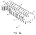
本発明は、外科用器具に関するものであり、様々な実施形態において、組織の切断及びステープル留めのために設計された、外科用切断及びステープル留め器具並びにステープルカートリッジに関する。 The present invention relates to surgical instruments and, in various embodiments, to surgical cutting and stapling instruments and staple cartridges designed for tissue cutting and stapling.
以下は請求されることも、されないこともある、本発明の実施形態の非網羅的なリストである。
1.外科用ステープラーのためのステープルカートリッジアセンブリであって、外科用ステープラーは、ステープルカートリッジアセンブリと面する関係にあるように構成されたアンビルを含み、ステープルカートリッジアセンブリは、
複数のステープル空洞を含むカートリッジ本体と、
ステープル空洞内に位置付けられた複数のステープルと、
第1組織厚さコンペンセータと、
カートリッジ本体に連結された保持具であって、第1組織厚さコンペンセータは、カートリッジ本体と保持具との中間に位置付けられる、保持具と、
保持具及び第1組織厚さコンペンセータの少なくとも一方に取り付けられた第2組織厚さコンペンセータであって、第2組織厚さコンペンセータは、アンビル取り付け部分を含み、保持具は第1組織厚さコンペンセータと第2組織厚さコンペンセータとの中間に位置付けられ、保持具は第1組織厚さコンペンセータと、組織厚さコンペンセータとの間から取り除かれるように構成され、第1及び第2組織厚さコンペンセータは、ステープル内に捕捉され、異なるステープル内で異なる圧迫された高さを呈するように構成される、第2組織厚さコンペンセータと、を含む、ステープルカートリッジアセンブリ。
2.第2組織厚さコンペンセータが表面を含み、アンビル取り付け部が第2組織厚さコンペンセータの表面上の接着剤を含む、実施形態1に記載のステープルカートリッジアセンブリ。
3.第2組織厚さコンペンセータの表面上の接着剤が、アンビルに第1保持力をもたらし、第2組織厚さコンペンセータと保持具及び第1組織厚さコンペンセータの少なくとも一方との間の取り付けが、第2保持力をもたらし、第1保持力は、第2保持力よりも高い、実施形態2に記載のステープルカートリッジアセンブリ。
4.第2組織厚さコンペンセータは更に、アンビル上の対応する位置合わせ機構と位置合わせするように構成された位置合わせ機構を含む、実施形態1〜3のいずれか1つに記載のステープルカートリッジアセンブリ。
5.第2組織厚さコンペンセータを保持具に取り外し可能に取り付けるように構成された接着剤を更に含む、実施形態1〜4のいずれか1つに記載のステープルカートリッジアセンブリ。
6.保持具はカートリッジ本体と取り外し可能に係合可能な複数のクリップを含み、クリップは、第1組織厚さコンペンセータが位置する隙間を画定するために、カートリッジ本体と係合するように構成されている、実施形態1〜5のいずれか1つに記載のステープルカートリッジアセンブリ。
7.保持具がアンビルの少なくとも一部に適合するように構成された複数の突起部を含み、複数の突起部は、保持具をアンビルと位置合わせさせるように構成される、実施形態1〜6のいずれか1つに記載のステープルカートリッジアセンブリ。
8.第2組織厚さコンペンセータは開口部を画定し、保持具は、開口部を通じて延びる突起部を含み、突起部はアンビルのチャネルと係合するように構成されている、実施形態1〜7のいずれか1つに記載のステープルカートリッジアセンブリ。
9.第2組織厚さコンペンセータが、アンビルの少なくとも一部と適合するように構成された複数の突起部を含み、複数の突起部はアンビルに対して移動し、第2厚さコンペンセータをアンビルに対して位置合わせするように構成されている、実施形態1〜8のいずれか1つに記載のステープルカートリッジアセンブリ。
10.第2組織厚さコンペンセータと連結されたソックス部を更に含み、ソックス部はアンビルに対し、その上を摺動するように構成される、実施形態1〜9のいずれか1つに記載のステープルカートリッジアセンブリ。
11.ソックス部及び第2組織厚さコンペンセータの少なくとも一方が、第2組織厚さコンペンセータがソックス部から引き離されることを可能にするように構成された穿孔部を画定する、実施形態10に記載のステープルカートリッジアセンブリ。
12.保持具が開口部を画定し、第2組織厚さコンペンセータが、保持具の開口部から延びるコネクタにより、第1組織厚さコンペンセータに接続される、実施形態1〜11のいずれか1つに記載のステープルカートリッジアセンブリ。
13.保持具により画定される開口部は、保持具が第1組織厚さコンペンセータ及び第2組織厚さコンペンセータから取り除かれる場合に、コネクタを切断するように構成された、切断縁部を含む、実施形態12に記載のステープルカートリッジアセンブリ。
14.保持具は、第2組織厚さコンペンセータと解放可能に係合するように構成された複数のクリップを含み、第2組織厚さコンペンセータは、アンビルと接着するように構成された接着剤表面を含み、複数のクリップは、接着剤表面がアンビルに接着した後に、第2組織厚さコンペンセータから外れるように構成されている、請求項1〜13のいずれか一項に記載のステープルカートリッジアセンブリ。
15.
ステープルカートリッジであって、
複数のステープル空洞を含むカートリッジ本体、及び
ステープル空洞内に位置付けられた複数のステープルを含むステープルカートリッジと、
保持具であって、
第1保持具プレート、
第2保持具プレート、
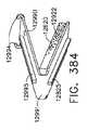
第1保持具プレート及び第2保持具プレートを接続するコネクタであって、第1保持具プレートは、第2保持具プレートに対し、コネクタを中心として枢動可能である、コネクタ、及び
第1保持具プレート及び第2保持具プレートの一方の上の第1カムを含む、保持具と、
カートリッジ本体に取り外し可能に取り付けられ、第1保持具プレートに取り外し可能に取り付けられた、第1生体適合性層と、
第2保持具プレートに取り外し可能に取り付けられた第2生体適合性層であって、第1生体適合性層及び第2生体適合性層は、ステープル内に捕捉されるように構成され、異なるステープル内で異なる圧迫された高さを呈する、第2生体適合性層と、
第1保持具プレートと第2保持具プレートとの中間に配置されるように構成され、第1位置と第2位置との間で保持具に対して移動するように構成されたスプレッダーであって、スプレッダーは、第1カムと係合するように構成された第2カムを含み、スプレッダーが第1位置から第2位置へと移動することにより、第1カム及び第2カムが相対移動し、第1保持具プレート及び第2保持具プレートが互いに離れるように枢動する、スプレッダーとを含む、カートリッジアセンブリシステム。
16.少なくとも1つの組織厚さコンペンセータを、外科用ステープラーに適用するための保持具アセンブリであって、外科用ステープラーは、ステープルカートリッジアセンブリと面する関係になるように構成されたアンビルを含み、保持具アセンブリは、
把持具と、
第1表面と、
第1表面と反対側に配置された第2表面と、
少なくとも1つの組織厚さコンペンセータと、
第2表面から延びる複数のクリップであって、クリップは、外科用ステープラーのステープルカートリッジ、及びステープルカートリッジチャネルの少なくとも一方に取り付けられるように構成される、複数のクリップとを含む、保持具アセンブリ。
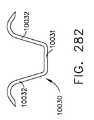
17.第1表面は、第1組織厚さコンペンセータ上の、対応する係合機構と連結するように構成された係合機構を含む、実施形態16に記載の保持具アセンブリ。
18.第2表面は、第2組織厚さコンペンセータ上の対応する係合機構に連結するように構成された係合機構を含む、実施形態16又は17に記載の保持具アセンブリ。
19.複数のクリップは第1の複数のクリップであり、保持具アセンブリは更に、第1表面から延びる第2の複数のクリップを更に含み、第2の複数のクリップは少なくとも1つの組織厚さコンペンセータと解放可能に係合するように構成され、第2の複数のクリップは、組織厚さコンペンセータが、外科用ステープラーのアンビルと結合した後に、組織厚さコンペンセータから係合離脱するように構成される、実施形態16〜18のいずれか1つに記載の保持具アセンブリ。
20.第1表面及び第2表面を通じて延びる開口部を更に含み、開口部を通じて第1及び第2組織厚さコンペンセータが接続され得る、実施形態16〜19のいずれか1つに記載の保持具アセンブリ。
21.開口部は、保持具が、第1及び第2組織厚さコンペンセータから取り除かれるときに、第1及び第2組織厚さコンペンセータを切り離すように構成された切断縁部を含む、実施形態20に記載の保持具アセンブリ。
22.第1表面から延びる複数の突起部を更に含み、突起部は外科用ステープラーのアンビルの少なくとも一部に適合するように構成され、突起部はアンビルに対して移動し、かつ少なくとも1つの組織厚さコンペンセータをアンビルと位置合わせするように構成される、実施形態16〜21のいずれか1つに記載の保持具アセンブリ。The following is a non-exhaustive list of embodiments of the present invention that may or may not be claimed.
1. A staple cartridge assembly for a surgical stapler, wherein the surgical stapler includes an anvil configured to face the staple cartridge assembly, the staple cartridge assembly comprising:
A cartridge body including a plurality of staple cavities;
A plurality of staples positioned within the staple cavity;
A first tissue thickness compensator;
A holder coupled to the cartridge body, wherein the first tissue thickness compensator is positioned intermediate the cartridge body and the holder;
A second tissue thickness compensator attached to at least one of the retainer and the first tissue thickness compensator, the second tissue thickness compensator including an anvil attachment portion, and the retainer includes the first tissue thickness compensator and Positioned intermediate the second tissue thickness compensator, the retainer is configured to be removed from between the first tissue thickness compensator and the tissue thickness compensator, the first and second tissue thickness compensators comprising: And a second tissue thickness compensator configured to be captured in the staple and exhibit different compressed heights in the different staples.
2. The staple cartridge assembly of
3. The adhesive on the surface of the second tissue thickness compensator provides a first retention force to the anvil, and attachment between the second tissue thickness compensator and the retainer and at least one of the first tissue thickness compensators is The staple cartridge assembly of
4). 4. The staple cartridge assembly according to any one of embodiments 1-3, wherein the second tissue thickness compensator further includes an alignment mechanism configured to align with a corresponding alignment mechanism on the anvil.
5.
6). The retainer includes a plurality of clips removably engageable with the cartridge body, the clips configured to engage the cartridge body to define a gap in which the first tissue thickness compensator is located. The staple cartridge assembly according to any one of Embodiments 1-5.
7). Any of Embodiments 1-6, wherein the retainer includes a plurality of protrusions configured to fit at least a portion of the anvil, the plurality of protrusions configured to align the holder with the anvil. A staple cartridge assembly according to any one of the preceding claims.
8). The second tissue thickness compensator defines an opening, and the retainer includes a protrusion extending through the opening, the protrusion configured to engage the channel of the anvil, any of embodiments 1-7 A staple cartridge assembly according to any one of the preceding claims.
9. The second tissue thickness compensator includes a plurality of protrusions configured to match at least a portion of the anvil, the plurality of protrusions moving relative to the anvil, and the second thickness compensator relative to the anvil. Embodiment 9. The staple cartridge assembly according to any one of the preceding embodiments, configured to align.
10. The staple cartridge of any one of embodiments 1-9, further comprising a sock portion coupled to the second tissue thickness compensator, wherein the sock portion is configured to slide over the anvil. assembly.
11. The staple cartridge of
12
13. Embodiments in which the opening defined by the retainer includes a cutting edge configured to cut the connector when the retainer is removed from the first tissue thickness compensator and the second tissue thickness compensator. The staple cartridge assembly according to
14 The retainer includes a plurality of clips configured to releasably engage a second tissue thickness compensator, and the second tissue thickness compensator includes an adhesive surface configured to adhere to the anvil. The staple cartridge assembly of
15.
A staple cartridge,
A cartridge body including a plurality of staple cavities, and a staple cartridge including a plurality of staples positioned within the staple cavities;
A holding tool,
A first retainer plate,
A second retainer plate,
A connector for connecting a first holder plate and a second holder plate, the first holder plate being pivotable about the connector with respect to the second holder plate, and a first holder A retainer including a first cam on one of the retainer plate and the second retainer plate;
A first biocompatible layer removably attached to the cartridge body and removably attached to the first retainer plate;
A second biocompatible layer removably attached to the second retainer plate, wherein the first biocompatible layer and the second biocompatible layer are configured to be captured within the staple and are different staples. A second biocompatible layer presenting different compressed heights therein,
A spreader configured to be disposed between the first holder plate and the second holder plate and configured to move relative to the holder between a first position and a second position. The spreader includes a second cam configured to engage the first cam, and the first cam and the second cam move relative to each other when the spreader moves from the first position to the second position. A spreader assembly including a spreader, wherein the first retainer plate and the second retainer plate pivot away from each other.
16. A holder assembly for applying at least one tissue thickness compensator to a surgical stapler, the surgical stapler including an anvil configured to face the staple cartridge assembly, the holder assembly Is
A gripping tool;
A first surface;
A second surface disposed opposite the first surface;
At least one tissue thickness compensator;
A plurality of clips extending from a second surface, the clips including a staple cartridge of a surgical stapler and a plurality of clips configured to be attached to at least one of the staple cartridge channels.
17. 17. The retainer assembly according to embodiment 16, wherein the first surface includes an engagement mechanism configured to couple with a corresponding engagement mechanism on the first tissue thickness compensator.
18. Embodiment 18. The retainer assembly according to
19. The plurality of clips is a first plurality of clips, the retainer assembly further includes a second plurality of clips extending from the first surface, the second plurality of clips being released with at least one tissue thickness compensator. The second plurality of clips configured to engage and disengage from the tissue thickness compensator after the tissue thickness compensator is coupled to the anvil of the surgical stapler. The retainer assembly according to any one of Forms 16-18.
20.
21.
22. The projection further includes a plurality of protrusions extending from the first surface, the protrusions configured to fit at least a portion of the anvil of the surgical stapler, the protrusions moving relative to the anvil, and at least one tissue thickness.
本発明の特徴及び利点、並びにそれらを実現する方法は、本発明の実施形態の以下の説明文を添付の図面と併せて参照することでより明らかとなり、また発明自体のより深い理解が得られるであろう。
対応する参照符合は、複数の図面を通じて対応する部材を示す。本明細書において説明される例示は、一形態による本発明の特定の実施形態を例示し、このような例示は、いかなる方法によっても本発明の範囲を限定するものとして解釈されない。 Corresponding reference characters indicate corresponding parts throughout the several views. The illustrations described herein illustrate specific embodiments of the invention according to one aspect, and such illustrations are not to be construed as limiting the scope of the invention in any way.
本出願の出願人はまた、以下に示す米国特許出願も所有し、それらのそれぞれの全内容が参照により本明細書に組み込まれる。
米国特許出願番号第12/894,311号、表題「SURGICAL INSTRUMENTS WITH RECONFIGURABLE SHAFT SEGMENTS」(代理人整理番号第6734USNP/100058号);
米国特許出願番号第12/894,340号、表題「SURGICAL STAPLE CARTRIDGES SUPPORTING NON−LINEARLY ARRANGED STAPLES AND SURGICAL STAPLING INSTRUMENTS WITH COMMON STAPLE−FORMING POCKETS」(代理人整理番号第END6735USNP/100059号);
米国特許出願番号第12/894,327号、表題「JAW CLOSURE ARRANGEMENTS FOR SURGICAL INSTRUMENTS」、(代理人整理番号第ENDEND6736USNP/100060号);
米国特許出願番号第12/894,351号、表題「SURGICAL CUTTING AND FASTENING INSTRUMENTS WITH SEPARATE AND DISTINCT FASTENER DEPLOYMENT AND TISSUE CUTTING SYSTEMS」(代理人整理番号第END6839USNP/100524号);
米国特許出願番号第12/894,338号、表題「IMPLANTABLE FASTENER CARTRIDGE HAVING A NON−UNIFORM ARRANGEMENT」(代理人整理番号第END6840USNP/100525号);
米国特許出願番号第12/894,369号、表題「IMPLANTABLE FASTENER CARTRIDGE COMPRISING A SUPPORT RETAINER」(代理人整理番号第END6841USNP/100526号);
米国特許出願番号第12/894,312号、表題「IMPLANTABLE FASTENER CARTRIDGE COMPRISING MULTIPLE LAYERS」(代理人整理番号第END6842USNP/100527);
米国特許出願番号第12/894,377号、表題「SELECTIVELY ORIENTABLE IMPLANTABLE FASTENER CARTRIDGE」、(代理人整理番号第END6843USNP/100528号);
米国特許出願番号第12/894,339号、表題「SURGICAL STAPLING INSTRUMENT WITH COMPACT ARTICULATION CONTROL ARRANGEMENT」、(代理人整理番号第END6847USNP/100532号);
米国特許出願番号第12/894,360号、表題「SURGICAL STAPLING INSTRUMENT WITH A VARIABLE STAPLE FORMING SYSTEM」、(代理人整理番号第END6848USNP/100533号);
米国特許出願番号第12/894,322号、表題「SURGICAL STAPLING INSTRUMENT WITH INTERCHANGEABLE STAPLE CARTRIDGE ARRANGEMENTS」、(代理人整理番号第END6849USNP/100534号);
米国特許出願番号第12/894,350号、表題「SURGICAL STAPLE CARTRIDGES WITH DETACHABLE SUPPORT STRUCTURES AND SURGICAL STAPLING INSTRUMENTS WITH SYSTEMS FOR PREVENTING ACTUATION MOTIONS WHEN A CARTRIDGE IS NOT PRESENT」、(代理人整理番号第END6855USNP/100540号);
米国特許出願番号第12/894,383号、表題「IMPLANTABLE FASTENER CARTRIDGE COMPRISING BIOABSORBABLE LAYERS」、(代理人整理番号第END6856USNP/100541号);
米国特許出願番号第12/894,389号、表題「COMPRESSIBLE FASTENER CARTRIDGE」、(代理人整理番号第END6857USNP/100542号);
米国特許出願番号第12/894,345号、表題「FASTENERS SUPPORTED BY A FASTENER CARTRIDGE SUPPORT」、(代理人整理番号第END6858USNP/100543号);
米国特許出願番号第12/894,306号、表題「COLLAPSIBLE FASTENER CARTRIDGE」、(代理人整理番号第END6859USNP/100544号);
米国特許出願番号第12/894,318号、表題「FASTENER SYSTEM COMPRISING A PLURALITY OF CONNECTED RETENTION MATRIX ELEMENTS」、(代理人整理番号第END6860USNP/100546号);
米国特許出願番号第12/894,330号、表題「FASTENER SYSTEM COMPRISING A RETENTION MATRIX AND AN ALIGNMENT MATRIX」、(代理人整理番号第END6861USNP/100547号);
米国特許出願番号第12/894,361号、表題「FASTENER SYSTEM COMPRISING A RETENTION MATRIX」、(代理人整理番号第END6862USNP/100548号);
米国特許出願番号第12/894,367号、表題「FASTENING INSTRUMENT FOR DEPLOYING A FASTENER SYSTEM COMPRISING A RETENTION MATRIX」、(代理人整理番号第END6863USNP/100549号);
米国特許出願番号第12/894,388号、表題「FASTENER SYSTEM COMPRISING A RETENTION MATRIX AND A COVER」、(代理人整理番号第END6864USNP/100550号);
米国特許出願番号第12/894,376号、表題「FASTENER SYSTEM COMPRISING A PLURALITY OF FASTENER CARTRIDGES」、(代理人整理番号第END6865USNP/100551号);
米国特許出願番号第13/097,865号、表題「SURGICAL STAPLER ANVIL COMPRISING A PLURALITY OF FORMING POCKETS」、(代理人整理番号第END6735USCIP1/100059CIP1号);
米国特許出願番号第13/097,936号、表題「TISSUE THICKNESS COMPENSATOR FOR A SURGICAL STAPLER」、(代理人整理番号第END6736USCIP1/100060CIP1号);
米国特許出願番号第13/097,954号、表題「STAPLE CARTRIDGE COMPRISING A VARIABLE THICKNESS COMPRESSIBLE PORTION」、(代理人整理番号第END6840USCIP1/100525CIP1号);
米国特許出願番号第13/097,856号、表題「STAPLE CARTRIDGE COMPRISING STAPLES POSITIONED WITHIN A COMPRESSIBLE PORTION THEREOF」、(代理人整理番号第END6841USCIP1/100526CIP1号);
米国特許出願番号第13/097,928号、表題「TISSUE THICKNESS COMPENSATOR FOR A SURGICAL STAPLER」、(代理人整理番号第END6842USCIP1/100527CIP1号);
米国特許出願番号第13/097,891号、表題「TISSUE THICKNESS COMPENSATOR FOR A SURGICAL STAPLER COMPRISING AN ADJUSTABLE ANVIL」、(代理人整理番号第END6843USCIP1/100528CIP1号);
米国特許出願番号第13/097,948号、表題「STAPLE CARTRIDGE COMPRISING AN ADJUSTABLE DISTAL PORTION」、(代理人整理番号第END6847USCIP1/100532CIP1);
米国特許出願番号第13/097,907号、表題「TISSUE THICKNESS COMPENSATOR FOR A SURGICAL STAPLER」、(代理人整理番号第END6848USCIP1/100533CIP1号);
米国特許出願番号第13/097,861号、表題「TISSUE THICKNESS COMPENSATOR COMPRISING PORTIONS HAVING DIFFERENT PROPERTIES」、(代理人整理番号第END6849USCIP1/100534CIP1号);
米国特許出願番号第13/097,869号、表題「STAPLE CARTRIDGE LOADING ASSEMBLY」、(代理人整理番号第END6855USCIP1/100540CIP1号);
米国特許出願番号第13/097,917号、表題「COMPRESSIBLE STAPLE CARTRIDGE COMPRISING ALIGNMENT MEMBERS」、(代理人整理番号第END6856USCIP1/100541CIP1号);
米国特許出願番号第13/097,873号、表題「STAPLE CARTRIDGE COMPRISING A RELEASABLE PORTION」、(代理人整理番号第END6857USCIP1/100542CIP1号);
米国特許出願番号第13/097,938号、表題「STAPLE CARTRIDGE COMPRISING COMPRESSIBLE DISTORTION RESISTANT COMPONENTS」、(代理人整理番号第END6858USCIP1/100543CIP1号);
米国特許出願番号第13/097,924号、表題「STAPLE CARTRIDGE COMPRISING A TISSUE THICKNESS COMPENSATOR」、(代理人整理番号第END6859USCIP1/100544CIP1号);
米国特許出願番号第13/242,029号、表題「SURGICAL STAPLER WITH FLOATING ANVIL」、(代理人整理番号第END6841USCIP2/100526CIP2号);
米国特許出願番号第13/242,066号、表題「CURVED END EFFECTOR FOR A STAPLING INSTRUMENT」、(代理人整理番号第END6841USCIP3/100526CIP3号);
米国特許出願番号第13/242,086号、表題「STAPLE CARTRIDGE INCLUDING COLLAPSIBLE DECK」、(代理人整理番号第END7020USNP/110374号);
米国特許出願番号第13/241,912号、表題「STAPLE CARTRIDGE INCLUDING COLLAPSIBLE DECK ARRANGEMENT」、(代理人整理番号第END7019USNP/110375号);
米国特許出願番号第13/241,922号、表題「SURGICAL STAPLER WITH STATIONARY STAPLE DRIVERS」、(代理人整理番号第END7013USNP/110377号);
米国特許出願番号第13/241,637号、表題「SURGICAL INSTRUMENT WITH TRIGGER ASSEMBLY FOR GENERATING MULTIPLE ACTUATION MOTIONS」、(代理人整理番号第END6888USNP3/110378号);及び
米国特許出願番号第13/241,629号、表題「SURGICAL INSTRUMENT WITH SELECTIVELY ARTICULATABLE END EFFECTOR」、(代理人整理番号第END6888USNP2/110379号)。The applicant of this application also owns the following US patent applications, the entire contents of each of which are incorporated herein by reference:
US patent application Ser. No. 12 / 894,311, titled “SURGICAL INSTRUMENTS WITH RECONFIGURE SHAFFT SEGMENTS” (Attorney Docket No. 6734 USNP / 100058);
US Patent Application No. 12 / 894,340, Title “SURGICAL STAPLE CARTRIDGES SUPPORTING NON-LINEARLY ARRANGED STAPLES AND SURGICAL STAPLING INSTRUMENTS WITH COMMAND STAMP
US patent application Ser. No. 12 / 894,327, entitled “JAW CLOSER ARRANGEMENTS FOR SURGITAL INSTRUMENTS” (Attorney Docket No. ENDEND6736USNP / 100060);
US Patent Application No. 12 / 894,351, Title “SURGICAL CUTTING AND FASTENING INSTRUMENTS WITH SEPARATE AND DISTINCT FASTENER DEPLOYMENT AND TISSUE CUTTING SYSTEMS”;
US patent application Ser. No. 12 / 894,338, titled “IMPLANTABLE FASTENER CARTRIGAGE HAVING A NON-UNIFORM ARRANGEMENT” (Attorney Docket No. END 6840 USNP / 100525);
US patent application Ser. No. 12 / 894,369, titled “IMPLANTABLE FASTENER CARTRIDGE COMPRISING A SUPPORT RETAINER” (Attorney Docket No. END6841USNP / 100526);
US patent application Ser. No. 12 / 894,312, titled “IMPLANTABLE FASTENER CARTRIDGE COMPRISING MULTIPLE LAYERS” (Attorney Docket No. END6842USNP / 100527);
US patent application Ser. No. 12 / 894,377, titled “SELECTIVELY ORIENTABLE IMPLANTABLE FASTENER CARTRIDGE” (Attorney Docket No. END6843USNP / 100528);
US patent application Ser. No. 12 / 894,339, title “SURGICAL STAPLING INSTRUMENT WITH COMPACT ACTULATION CONTROL ARRANGEMENT” (Attorney Docket No. END6847USNP / 100532);
US patent application Ser. No. 12 / 894,360, titled “SURGICAL STAPLING INSTRUMENT WITH A VARIABLE STAPLE FORMING SYSTEM”, (Attorney Docket No. END6848USNP / 100533);
US patent application Ser. No. 12 / 894,322, title “SURGICAL STAPLING INSTRUMENT WITH INTERCHANGABLE STAPLE CARTRIDGE ARRANGEMENTS” (Attorney Docket No. END6849USNP / 100534);
U.S. Patent Application No. 12 / 894,350, entitled "SURGICAL STAPLE CARTRIDGES WITH DETACHABLE SUPPORT STRUCTURES AND SURGICAL STAPLING INSTRUMENTS WITH SYSTEMS FOR PREVENTING ACTUATION MOTIONS WHEN A CARTRIDGE IS NOT PRESENT", (Attorney Docket No. END6855USNP / 100540) ;
US patent application Ser. No. 12 / 894,383, title “IMPLANTABLE FASTENER CARTRIDGE COMPRISING BIO ABSORBABLE LAYERS” (Attorney Docket No. END 6856 USNP / 100541);
US patent application Ser. No. 12 / 894,389, title “COMPRESSABLE FASTENER CARTRIDGE” (Attorney Docket No. END6857USNP / 100542);
US patent application Ser. No. 12 / 894,345, entitled “FASTENERS SUPPORTED BY A FASTENER CARTRIDGE SUPPORT” (Attorney Docket No. END6858USNP / 100543);
US patent application Ser. No. 12 / 894,306, title “COLLAPSIBLE FASTENER CARTRIDGE” (Attorney Docket No. END6859USNP / 1100454);
US patent application Ser. No. 12 / 894,318, titled “FASTENER SYSTEM COMPRISING A PLULARITY OF CONNECTED RETENTION MATRIX ELEMENTS”, (Attorney Docket No. END6860USNP / 100546);
US patent application Ser. No. 12 / 894,330, titled “FASTENER SYSTEM COMPRISING A RETENTION MATRIX AND AN ALIGNMENT MATRIX” (Attorney Docket No. END6681USNP / 100547);
US patent application Ser. No. 12 / 894,361, entitled “FASTENER SYSTEM COMPRISING A RETENTION MATRIX”, (Attorney Docket No. END 6862 USNP / 100548);
US patent application Ser. No. 12 / 894,367, titled “FASTENING INSTRUMENT FOR DEPLOYING A FASTENER SYSTEM COMPRISING A RETENTION MATRIX” (Attorney Docket No. END 6863USNP / 100549);
US patent application Ser. No. 12 / 894,388, titled “FASTENER SYSTEM COMPRISING A RETENTION MATRIX AND A COVER” (Attorney Docket No. END 6864 USNP / 100550);
US patent application Ser. No. 12 / 894,376, entitled “FASTENER SYSTEM COMPRISING A PLULARITY OF FASTENER CARTRIDGES” (Attorney Docket No. END6865USNP / 100551);
U.S. Patent Application No. 13 / 097,865, entitled "SURGICAL STAPLLER ANVIL COMPRISING A PLURALITY OF FORMING POCKETS", (Attorney Docket No. END 6735 USCIP1 / 100059CIP1);
US Patent Application No. 13 / 097,936, entitled “TISSUE THICKNESS COMPENSATOR FOR A SURGICAL STAPLER” (Attorney Docket No. END6736USCIP1 / 100060CIP1);
U.S. Patent Application No. 13 / 097,954, entitled "STAPLE CARTRIDGE COMPRISING A VARIABLE THICKNESS COMPRESIBLE POTION", (Attorney Docket No. END6840USCIP1 / 100525CIP1);
US Patent Application No. 13 / 097,856, entitled “STAPLE CARTRIDGE COMPRISING STAPLES POSITIONED WITHIN A COMPRESIBLE PORTION THEREOF” (Attorney Docket No. END6841USCIP1 / 100526CIP1);
US Patent Application No. 13 / 097,928, title “TISSUE THICKNESS COMPENSATOR FOR A SURGICAL STAPLER” (Attorney Docket No. END6842USCIP1 / 100527CIP1);
US Patent Application No. 13 / 097,891, entitled “TISSUE THICKNESS COMPENSATOR FOR A SURGICAL STAPLERS COMPRISING AN ADJUSTABLE ANVIL” (Attorney Docket No. END6843USCIP1 / 100528CIP1);
US Patent Application No. 13 / 097,948, entitled “STAPLE CARTRIDGE COMPRISING AN ADJUSTABLE DISPORTION” (Attorney Docket No. END 6847 USCIP1 / 10032 CIP1);
US Patent Application No. 13 / 097,907, titled “TISSUE THICKNESS COMPENSATOR FOR A SURGICAL STAPLER” (Attorney Docket No. END6848USCIP1 / 1003353CIP1);
US Patent Application No. 13 / 097,861, title “TISSUE THICKNESS COMPENSOR COMPRISING PORTIONS HAVING DIFFERENT PROPERITES” (Attorney Docket No. END6849USCIP1 / 100534CIP1);
U.S. Patent Application No. 13 / 097,869, entitled "STAPLE CARTRIDGE LOADING ASSEMBLY" (Attorney Docket No. END6855 USCIP1 / 100540CIP1);
U.S. Patent Application No. 13 / 097,917, title "COMPRESSABLE STAPLE CARTRIDGE COMPRISING ALIGNMENT MEMBERS" (Attorney Docket No. END6856USCIP1 / 1001541CIP1)
U.S. Patent Application No. 13 / 097,873, entitled "STAPLE CARTRIDGE COMPRISING A RELEASABLE PORTITION" (Attorney Docket No. END6857USCIP1 / 100542CIP1);
U.S. Patent Application No. 13 / 097,938, title "STAPLE CARTRIDGE COMPRISING COMPRESIBLE DISTORTION RESISTANT COMPONENTS" (Attorney Docket No. END6858USCIP1 / 1003153CIP1);
U.S. Patent Application No. 13 / 097,924, entitled "STAPLE CARTRIDGE COMPRISING A TISSUE TICHKNESS COMPENSATOR" (Attorney Docket No. END6859USCIP1 / 100544CIP1);
US patent application Ser. No. 13 / 242,029, title “SURGICAL STAPLER WITH FLOATING ANVIL” (Attorney Docket No. END6841 USCIP2 / 100526CIP2);
US patent application Ser. No. 13 / 242,066, title “CURVED END EFFECTOR FOR A STAPLING INSTRUMENT” (Attorney Docket No. END6841 USCIP3 / 100526CIP3);
US Patent Application No. 13 / 242,086, titled “STAPLE CARTRIDGE INCLUDING COLLAPSIBLE DECK” (Attorney Docket No. END 7020 USNP / 110374);
US Patent Application No. 13 / 241,912, entitled “STAPLE CARTRIDGE INCLUDING COLLAPSIBLE DECK ARRANGEMENT” (Attorney Docket No. END7019 USNP / 110375);
U.S. Patent Application No. 13 / 241,922, entitled "SURGICAL STAPLIER WITH STATIONARY STAY DRIVER" (Attorney Docket No. END7013 USNP / 110377);
US patent application no. 13 / 241,637, title “SURGICAL INSTRUMENT WITH TRIGGER ASSEMBLY FOR GENERATION MULTIPACTION MOTIONS”, (Attorney Docket Number END6888USNP3 / 11378); , Title "SURGICAL INSTRUMENT WITH SELECTIVELY ARTICULABLE END EFFECTOR" (Attorney Docket No. END6888USNP2 / 110379).
本出願の出願人はまた、本明細書と同日に出願され、それらの全ての内容がそれぞれ、参照によって本明細書に組み込まれる、以下に示す米国特許出願も所有する。
米国特許出願番号第_______________号、表題「TISSUE THICKNESS COMPENSATOR COMPRISING A PLURALITY OF CAPSULES」(代理人整理番号第END6864USCIP1/100550CIP1号);
米国特許出願番号第_______________号、表題「TISSUE THICKNESS COMPENSATOR COMPRISING A PLURALITY OF LAYERS」(代理人整理番号第END6864USCIP2/100550CIP2);
米国特許出願番号第_______________号、表題「EXPANDABLE TISSUE THICKNESS COMPENSATOR」(代理人整理番号第END6843USCIP2/100528CIP2号);
米国特許出願番号第_______________号、表題「TISSUE THICKNESS COMPENSATOR COMPRISING A RESERVOIR」(代理人整理番号第END6843USCIP3/100528CIP3号);
米国特許出願番号第_______________号、表題「TISSUE THICKNESS COMPENSATOR COMPRISING AT LEAST ONE MEDICAMENT」(代理人整理番号第END6843USCIP5/100528CIP5号);
米国特許出願番号第_______________号、表題「TISSUE THICKNESS COMPENSATOR COMPRISING CONTROLLED RELEASE AND EXPANSION」(代理人整理番号第END6843USCIP6/100528CIP6号);
米国特許出願番号第_______________号、表題「TISSUE THICKNESS COMPENSATOR COMPRISING FIBERS TO PRODUCE A RESILIENT LOAD」(代理人整理番号第END6843USCIP7/100528CIP7号);
米国特許出願番号第_______________号、表題「TISSUE THICKNESS COMPENSATOR COMPRISING STRUCTURE TO PRODUCE A RESILIENT LOAD」(代理人整理番号第END6843USCIP8/100528CIP8号);
米国特許出願番号第_______________号、表題「TISSUE THICKNESS COMPENSATOR COMPRISING RESILIENT MEMBERS」(代理人整理番号第END6843USCIP9/100528CIP9号);
米国特許出願番号第_______________号、表題「METHODS FOR FORMING TISSUE THICKNESS COMPENSATOR ARRANGEMENTS FOR SURGICAL STAPLERS」(代理人整理番号第 END6843USCIP10/100528CP10号);
米国特許出願番号第_______________号、表題「TISSUE THICKNESS COMPENSATORS」(代理人整理番号第END6843USCIP11/100528CP11号);
米国特許出願番号第_______________号、表題「LAYERED TISSUE THICKNESS COMPENSATOR」(代理人整理番号第END6843USCIP12/100528CP12号);
米国特許出願番号第_______________号、表題「TISSUE THICKNESS COMPENSATORS FOR CIRCULAR SURGICAL STAPLERS」(代理人整理番号第END6843USCIP13/100528CP13号);
米国特許出願番号第_______________号、表題「TISSUE THICKNESS COMPENSATOR COMPRISING CAPSULES DEFINING A LOW PRESSURE ENVIRONMENT」(代理人整理番号第END7100USNP/110601号);
米国特許出願番号第_______________号、表題「TISSUE THICKNESS COMPENSATOR COMPRISED OF A PLURALITY OF MATERIALS」(代理人整理番号第END7101USNP/110602号);
米国特許出願番号第_______________号、表題「MOVABLE MEMBER FOR USE WITH A TISSUE THICKNESS COMPENSATOR」(代理人整理番号第END7107USNP/110603号);
米国特許出願番号第_______________号、表題「TISSUE THICKNESS COMPENSATOR COMPRISING A PLURALITY OF MEDICAMENTS」(代理人整理番号第END7102USNP/110604号);
米国特許出願番号第_______________号、表題「TISSUE THICKNESS COMPENSATOR AND METHOD FOR MAKING THE SAME」(代理人整理番号第END7103USNP/110605号);
米国特許出願番号第_______________号、表題「TISSUE THICKNESS COMPENSATOR COMPRISING CHANNELS」(代理人整理番号第END7104USNP/110606号);
米国特許出願番号第_______________号、表題「TISSUE THICKNESS COMPENSATOR COMPRISING TISSUE INGROWTH FEATURES」(代理人整理番号第END7105USNP/110607号);及び
米国特許出願番号第_______________号、表題「DEVICES AND METHODS FOR ATTACHING TISSUE THICKNESS COMPENSATING MATERIALS TO SURGICAL STAPLING INSTRUMENTS」(代理人整理番号第END7106USNP/110608号)。The applicant of this application also owns the following US patent applications filed on the same day as this specification, the entire contents of each of which are hereby incorporated by reference:
U.S. Patent Application No. ______________, title "TISSUE THICKNESS COMPENSATOR COMPRISING A PLULARITY OF CAPSULES" (Attorney Docket No. END 6864 USCIP1 / 100550CIP1);
U.S. Patent Application No. ______________, title "TISSUE THICKNESS COMPENSATOR COMPRISING A PLULARITY OF LAYERS" (Attorney Docket No. END 6864USCIP2 / 100550CIP2);
US Patent Application No. ______________, title "EXPANDABLE TISSUE TICHKNESS COMPENSATOR" (Attorney Docket No. END6843USCIP2 / 100528CIP2);
US patent application number ______________, title "TISSUE THICKNESS COMPENSATOR COMPRISING A RESERVOIR" (Attorney Docket Number END6843USCIP3 / 100528CIP3);
US patent application number ______________, title "TISSUE THICKNESS COMPENSATOR COMPRISING AT LEAST ONE MEDIACAMENT" (Attorney Docket Number END6843USCIP5 / 100528CIP5);
U.S. Patent Application No. ______________, title "TISSUE THICKNESS COMPENSATOR COMPRISING CONTROLLED RELEASE AND EXPANSION" (Attorney Docket No. END6843USCIP6 / 100528CIP6);
US patent application number ______________, title "TISSUE THICKNESS COMPENSATOR COMPRISING FIBERS TO PRODUCE A RESILIENT LOAD" (Attorney Docket Number END6843USCIP7 / 100528CIP7)
US Patent Application No. ______________, title "TISSUE THICKNESS COMPENSATOR COMPRISING STRUCTURE TO PRODUCE A RESILIENT LOAD" (Attorney Docket No. END6843USCIP8 / 100528CIP8)
U.S. Patent Application No. ______________, title "TISSUE THICKNESS COMPENSATOR COMPRISING COMPRISING RESILENT MEMBERS" (Attorney Docket No. END6843USCIP9 / 100528CIP9);
US Patent Application No. ______________, title "METHODS FOR FORMING TISSUE THICKNESS COMPENSATOR ARRANGEMENTS FOR SURGICAL STAPLERS" (Attorney Docket No. END6843USCIP10)
US Patent Application No. ______________, title “TISSUE THICKNESS COMPENSATORS” (Attorney Docket No. END6843USCIP11 / 100528CP11);
US patent application number ______________, title "LAYERED TISSUE THICKNESS COMPENSATOR" (Attorney Docket No. END6843USCIP12 / 100528CP12);
US Patent Application No. ______________, title "TISSUE THICKNESS COMPENSATORS FOR CIRCULAR SURGICAL STAPLERS" (Attorney Docket No. END6843USCIP13 / 100528CP13);
U.S. Patent Application No. ______________, title "TISSUE THICKNESS COMPENSATOR COMPRISING CAPSULES DEFING A LOW PRESURE ENVIRONMENT" (Attorney Docket No. END7100USNP / 110601)
U.S. Patent Application No. ______________, title "TISSUE THICKNESS COMPENSATOR COMPRISED OF A PLULARITY OF MATERIALS" (Attorney Docket Number END7101USNP / 110602);
US patent application number ______________, title "MOVABLE MEMBER FOR USE WITH A TISSUE TICHKNESS COMPENSATOR" (Attorney Docket No. END7107USNP / 110603);
US Patent Application No. ______________, title "TISSUE THICKNESS COMPENSATOR COMPRISING A PLULARITY OF MEDICAMENTS" (Attorney Docket No. END7102USNP / 110604);
U.S. Patent Application No. ______________, title "TISSUE THICKNESS COMPENSATOR AND METHOD FOR MAKING THE SAME" (Attorney Docket No. END 7103 USNP / 110605);
U.S. Patent Application No. ______________, title "TISSUE THICKNESS COMPENSATOR COMPRISING CHANNELS" (Attorney Docket No. END7104 USNP / 110606);
U.S. Patent Application Serial No. _______________, entitled "TISSUE THICKNESS COMPENSATOR COMPRISING TISSUE INGROWTH FEATURES" (Attorney Docket No. END7105USNP / 110607); and U.S. Patent Application Serial No. _______________, entitled "DEVICES AND METHODS FOR ATTACHING TISSUE THICKNESS COMPENSATING MATERIALS TO SURGICAL STAPLING INSTRUMENTS "(agent reference number END7106USNP / 110608).
本明細書で開示される装置並びに方法の構造、機能、製造、及び使用の原理の全体的な理解が与えられるよう、特定の例示的実施形態について以下に説明する。これらの実施形態の1つ又は2つ以上の例を添付図面に示す。通常の当業者は、本明細書に明確に記載され、添付の図面に示される装置及び方法が、非限定の代表的な実施形態であることを理解するであろう。1つの例示的な実施形態との関連において例示又は説明された特徴は、他の実施形態の特徴と組み合わせることができる。このような修正及び変形は、本発明の範囲に含まれる。 Certain exemplary embodiments are described below to provide a general understanding of the principles of structure, function, manufacture, and use of the devices and methods disclosed herein. One or more examples of these embodiments are illustrated in the accompanying drawings. Those of ordinary skill in the art will appreciate that the devices and methods specifically described herein and illustrated in the accompanying drawings are non-limiting exemplary embodiments. Features illustrated or described in the context of one exemplary embodiment may be combined with features of other embodiments. Such modifications and variations are included in the scope of the present invention.
物品又は製品を形成するか、ないしは別の方法により生成するための、本明細書において開示又は請求される方法のいずれかが、問題の物品又は製品の全部又は一部を製造、形成、ないしは別の方法で生成するために利用されてもよく、このような方法が、問題の物品又は製品の一部を製造、形成、ないしは別の方法で製造するために利用される場合、物品又は製品の残りは、本明細書において開示及び請求される、物品又は製品を製造、形成ないしは別の方法で生成するための、他の方法のいずれかを利用することを含む、いずれかの方法により生成され得、このように生成された様々な部分がなんらかの方法により組み合わされてもよい。同様に、本明細書において開示又は請求される物品又は製品が、単独で存在してもよく、これと適合する、このように開示されるいずれかの他の物品又は製品と、組み合わされるか、若しくはその一体部分として存在してもよい。したがって、物品、製品、又は方法に関連して例示又は記載される特定の特徴、構造、又は特性は、1つ又は2つ以上の他の適合する物品、製品、又は方法の特徴、構造、又は特性と、全体的又は部分的に、制限なく組み合わせることができる。このような修正及び変形は、本発明の範囲に含まれる。 Any of the methods disclosed or claimed herein for forming or otherwise producing an article or product may produce, form, or otherwise produce all or part of the article or product in question. And if such a method is used to manufacture, form, or otherwise manufacture a portion of the article or product in question, The remainder is produced by any method, including utilizing any of the other methods disclosed and claimed herein for manufacturing, forming or otherwise producing the article or product. Thus, the various parts thus generated may be combined in some way. Similarly, an article or product disclosed or claimed herein may be present alone or in combination with any other article or product so disclosed that is compatible therewith, Alternatively, it may exist as an integral part thereof. Thus, a particular feature, structure, or characteristic illustrated or described in connection with an article, product, or method is a feature, structure, or characteristic of one or more other suitable articles, products, or methods. The properties can be combined in whole or in part without limitation. Such modifications and variations are included in the scope of the present invention.
特定の図面又はそれ以外を参照として、本発明の一定の実施形態又は一定の物品、製品、又は方法が一定の構造、特性、又は特徴を含むことが開示される場合、これは、これらの構造、特性、又は特徴が、いずれかの適合性のある組み合わせにおいて、問題の物品、製品、又は方法において具現化され得ることを意味することが読者により理解される。特に、多くの任意の構造、特性、又は特徴はまた、構造、特性、又は特徴が互いに代替として開示される場合を除き、構造、特性、又は特徴の全ての組み合わせを開示するものとしても理解されるべきである。このような構造、特性、又は特徴が、互いの代替として開示される場合、これは互いに置換されたこれらの代替物を開示するものとして理解されるべきである。 Where certain embodiments of the invention or certain articles, products, or methods are disclosed with reference to certain drawings or otherwise, it is disclosed that these structures include certain structures, features, or characteristics. It is understood by the reader that the feature, characteristic, or feature may be embodied in the article, product, or method in question in any compatible combination. In particular, many arbitrary structures, properties, or characteristics are also understood to disclose all combinations of structures, characteristics, or features, except where structures, characteristics, or features are disclosed as alternatives to each other. Should be. Where such structures, characteristics, or features are disclosed as alternatives to each other, this is to be understood as disclosing those alternatives that are substituted for each other.
「近位」及び「遠位」という用語は、本明細書において、外科用器具のハンドル部分を操作する臨床医を基準にして用いられている。「近位」という用語は、臨床医に最も近い部分を指し、「遠位」という用語は、臨床医から離れた位置にある部分を指す。便宜上、及び明確性のために、「垂直」、「水平」、「上」、「下」などの、空間的用語は、本明細書では、図面に関連して使用し得ることが更に理解されよう。しかしながら、外科用器具は、多くの向き及び位置で使用されるものであり、これらの用語は、限定的及び/又は絶対的であることを意図したものではない。 The terms “proximal” and “distal” are used herein with reference to the clinician operating the handle portion of the surgical instrument. The term “proximal” refers to the portion closest to the clinician, and the term “distal” refers to the portion that is remote from the clinician. For convenience and clarity, it is further understood that spatial terms such as “vertical”, “horizontal”, “top”, “bottom” may be used herein in connection with the drawings. Like. However, surgical instruments are used in many orientations and positions, and these terms are not intended to be limiting and / or absolute.
腹腔鏡下及び最小侵襲の外科手技を実施するための様々な例示的な装置及び方法が提供される。しかしながら、本明細書で開示する様々な方法及び装置が、例えば開放的な外科手技を含めて、多数の外科手技及び用途で用いられ得ることが、読者には容易に理解されよう。本明細書の「発明を実施するための形態」を読み進むにつれて、読者は、本明細書に開示される様々な器具が、例えば、天然の開口部を通じて、組織に形成された切開又は穿刺穴を通じてなど、任意のやり方で体内に挿入され得ることを更に理解するであろう。これらの器具の実働部分すなわちエンドエフェクタ部分は、患者の体内に直接に挿入されてもよく、又は、外科用器具のエンドエフェクタ及び細長シャフトを進めることが可能な実働チャネルを有するトロカールのようなアクセス装置を通じて挿入されてもよい。 Various exemplary devices and methods are provided for performing laparoscopic and minimally invasive surgical procedures. However, the reader will readily appreciate that the various methods and devices disclosed herein can be used in numerous surgical procedures and applications, including, for example, open surgical procedures. As one proceeds with the “Mode for Carrying Out the Invention” herein, the reader will be aware that the various instruments disclosed herein may be incised or puncture holes formed in tissue, eg, through natural openings. It will be further understood that it can be inserted into the body in any manner, such as through. The active or end effector portions of these instruments may be inserted directly into the patient's body, or a trocar-like access having a working channel capable of advancing the end effector and elongated shaft of the surgical instrument. It may be inserted through the device.
図面に戻り、図面では、同様の参照符号が、複数の図を通じて同様の構成要素を示している。図1は、いくつかの固有の利点を実施できる外科用器具10を示している。外科用ステープリング器具10は、これに動作可能に取り付けられた、様々な形状及び大きさのエンドエフェクタ12を操作及び/又は作動させるように設計される。図1〜1Eにおいて、エンドエフェクタ12は、エンドエフェクタ12の下方ジョー13を形成する細長チャネル14を含む。細長いチャネル14は、「埋め込み可能な」ステープカートリッジ30を支持するように構成され、またエンドエフェクタ12の上方ジョー15として機能するアンビル20を動作可能に支持する。 Returning to the drawings, like reference numerals indicate like elements throughout the several views. FIG. 1 illustrates a
細長チャネル14は、300 & 400シリーズ、17−4 & 17−7ステンレススチール、チタンなどから作製されてもよく、離間した側壁16で形成されてもよい。アンビル20は、例えば、300 & 400シリーズ、17−4 & 17−7ステンレススチール、チタンなどから作製されてもよく、内部に形成される複数のステープル形成ポケット23を有する、一般的に22として標識される、ステープル形成下面を有し得る。図1B〜1Eを参照されたい。加えて、アンビル20は、そこから近位方向に突出する、二又の傾斜アセンブリ24を有する。アンビルピン26は、細長いチャネル14の側壁16内の対応するスロット又は開口部18内に受容される、傾斜アセンブリ24の各側壁から突出し、ここに可動又は枢動可能に取り付けることを容易にする。 The
埋め込み可能なステープルカートリッジが、本明細書において開示される外科用器具の様々な実施形態で利用され得る。特定のステープルカートリッジ構成及び構造は、以下で更に詳細に記載される。しかしながら、図1Aにおいて、埋め込み可能なステープルカートリッジ30が示される。ステープルカートリッジ30は、内部に形成されていない金属ステープル32が支持されている、例えば、酸化再生セルロース(「ORC」)又は生体吸収性フォームなどの圧縮可能な止血材料からなる、本体部分31を有する。ステープルが影響を受け、止血材料が導入及び配置処理中に活性化することを防ぐため、カートリッジ全体が、生分解性フィルム38、例えば、商標名PDS(登録商標)において販売されるポリジオキサノンフィルム、又はポリグリセロールセバケート(PGS)フィルム、又はPGA(商標Vicrylの商標名で販売されるポリグリセロール酸)、PCL(ポリカプロラクトン)、PLA、若しくはPLLA(ポリ乳酸)、PHA(ポリヒドロキシアルカノエート)、PGCL(商標名Monocrylで販売されるポリグレカプロン25)、又はPGA、PCL、PLA、PDSの複合物(破裂するまでは不透過性である)から形成される他の生分解性フィルムで、コーティング又は被覆され得る。ステープルカートリッジ30の本体31は、図示されるように、細長いチャネル14内に取り外し可能に支持されるような大きさであり、それによって、アンビル20がステープルカートリッジ30と接触する際に、内部の各ステープル32が、アンビル内の対応するステープル形成ポケット23と位置合わせされる。 Implantable staple cartridges can be utilized in various embodiments of the surgical instruments disclosed herein. Specific staple cartridge configurations and structures are described in further detail below. However, in FIG. 1A, an
使用中、一度エンドエフェクタ12が標的組織に隣接するように位置付けられると、エンドエフェクタ12は、ステープルカートリッジ30の上面36と、アンビル20のステープル形成表面22との間に、標的組織を捕捉又はクランプするように操作される。ステープル32は、細長いチャネル14と実質的に平行な経路内でアンビル20を動かして、ステープル形成表面22、及びより具体的には内部のステープル形成ポケット23を、ステープルカートリッジ30の上面36と実質的に同時に接触されることによって形成される。アンビル20がステープルカートリッジ30内に動き続けると、ステープル32の脚部34はアンビル20内の対応するステープル形成ポケット23に接触して、ステープル脚部34を折り曲げ、ステープル32を「B字型」に形成するように機能する。アンビル20の細長チャネル14への移動は、ステープル32を更に圧縮して、所望の最終的に形成される高さ「FF」へと形成する。 In use, once the
上記のステープル形成プロセスは、図1B〜1E内で一般的に示される。例えば図1Bは、アンビル20と埋め込み可能なステープルカートリッジ30の上面36との間に標的組織「T」を有する、エンドエフェクタ12を例示する。図1Cは、アンビル20の初期クランピング位置を例示し、アンビル20は標的組織「T」の上に閉鎖されて、アンビル20とステープルカートリッジ30の上面36との間に標的組織「T」をクランプする。図1Dは、初期ステープル形成を例示し、アンビル20はステープルカートリッジ30を圧縮しはじめ、それによってステープル32の脚部34は、アンビル20内のステープル形成ポケット23によって形成され始めている。図1Eは、明確性の目的のためにアンビル20が取り除かれた、標的組織「T」を貫通してその最終的な形成状態にある、ステープル32を例示する。一度ステープル32が標的組織「T」に形成及び締結されると、外科医はアンビル20を開放位置へと移動させて、エンドエフェクタ12が患者から引き抜かれる間、カートリッジ本体31及びステープル32が標的組織に固定されたままとなることを可能にする。エンドエフェクタ12は、2つのジョー13、15が一緒にクランピングされると、全てのステープルを同時に形成する。残っている「折り畳み式」本体材料31は、止血剤(ORC)及びステープルのライン補強部(PGA、PDS又は上記の他のいずれかのフィルム組成38)の両方として機能する。また、ステープル32は、形成中において、カートリッジ本体31を離れることはないため、ステープル32が形成中に不適切に形成される可能性は極小化される。本明細書において使用するとき、用語「埋め込み可能な」とは、ステープルに加えて、ステープルを支持するカートリッジ本体の材料もまた、患者内に留まり、最終的には患者の身体に吸収され得ることを意味する。そのような埋め込み可能なステープルカートリッジは、発射された後に全体がエンドエフェクタ内に位置したまま残る従来のカートリッジ構成とは区別される。 The above staple forming process is shown generally in FIGS. For example, FIG. 1B illustrates the
様々な実施において、エンドエフェクタ12は、ハンドルアセンブリ100から突出する細長いシャフトアセンブリ40と連結されるように構成される。エンドエフェクタ12(閉鎖時)及び細長いシャフトアセンブリ40は、同様の断面形状を有してもよく、トロカール管又は別の形状のアクセス器具内の作業チャネルを動作可能に通過するような大きさであり得る。本明細書において使用するとき、用語「動作可能に通過」とは、エンドエフェクタ及び細長いシャフトアセンブリの少なくとも一部分が、チャネル又はチューブ開口部を通じて挿入されるか、又は通過することができ、外科用ステープリング手技を完了するために必要性に応じて内部で操作され得ることを意味する。閉鎖位置にあるとき、エンドエフェクタ12のジョー13及び15は、およそ円形の横断面形状をエンドエフェクタに与えることができ、その形状により、エンドエフェクタが円形の通路/開口部を通り抜けることが容易となる。しかしながら、本発明のエンドエフェクタ、並びに細長シャフトアセンブリは、考えられる限りでは、非円形の横断面形状を有するアクセス通路及び開口部を通り抜けることができる他の横断面形状を与えられ得る。したがって、閉鎖したエンドエフェクタの横断面の全体的な大きさは、エンドエフェクタを通すことが意図される通路又は開口部の大きさに関連付けられる。したがって、あるエンドエフェクタは例えば、「5mmの」エンドエフェクタと呼ばれてもよく、これは、直径が少なくとも約5mmである開口部をそのエンドエフェクタが動作可能に通り抜け得ることを意味する。 In various implementations, the
細長シャフトアセンブリ40は、閉鎖位置にあるときのエンドエフェクタ12の外径と実質的に同じである外径を有してもよい。例えば、5mmエンドエフェクタは、5mmの断面直径を有する、細長いシャフトアセンブリ40と連結されてもよい。しかしながら、本発明の詳細な説明を読み進めると、本発明が、異なる大きさのエンドエフェクタに関連して有効に使用され得ることが明らかにある。例えば、10mmのエンドエフェクタが、5mmの横断面直径を有する細長シャフトに結合されてもよい。逆に、10mm以上のアクセス開口部又は経路が提供されるこれらの用途において、細長いシャフトアセンブリ40は、10mm(又はそれ以上)の断面直径を有してもよいが、また5mm又は10mmのエンドエフェクタを作動させることもできる。したがって、外側シャフト40は、これに取り付けられる閉鎖したエンドエフェクタ12の外径と同じ、又はこれと異なる外径を有してもよい。 The
示されるように、細長いシャフトアセンブリ40は、ハンドルアセンブリ100からほぼ直線上に遠位方向に延びて、長手方向軸A−A画定する。例えば、細長シャフトアセンブリ40は、約229〜406mm(9〜16インチ)の長さであり得る。しかし、細長シャフトアセンブリ40は別の長さであり得、その内側に接合箇所を有することができ、下記で詳しく説明されているように、シャフト又はハンドルアセンブリの他の部分に対してエンドエフェクタ12のアーティキュレーションを容易にするように構成し得る。細長シャフトアセンブリ40は、ハンドルアセンブリ100からエンドエフェクタ12まで延びる、スパイン部材50を含む。エンドエフェクタ12の細長チャネル14の近位端は、そこから突出する一対の保持トラニオン17を有し、これはスパイン部材50の遠位端内に提供される、対応するトラニオン開口部又は受台52に受容される大きさであり、エンドエフェクタ12が、細長シャフトアセンブリ40に取り外し可能に連結されることを可能にする。スパイン部材50は、例えば、6061又は7075アルミニウム、ステンレススチール、チタンなどから作製されてもよい。 As shown, the
ハンドルアセンブリ100は、組み立てる目的のために、2つ又は3つ以上の部品で作製され得る、ピストルグリップタイプのハウジングを含む。例えば、図示されるハンドルアセンブリ100は、右手ケース部材102、及び左手ケース部材を含み(図示なし)を含み、これらは、ポリマー又はプラスチック部材から作製され、互いに噛み合うように設計される。このような場合、部材は、スナップ機能、ペグ、及びその内側に成形又は形成されたソケットにより、及び/又は接着剤、ねじ等により貼り合わせることができる。脊椎部材50は、その上部に形成されたフランジ56を有する近位端54を有する。フランジ56は、各ケース部材102、104から内側に突出する噛み合うリブ108により形成される溝106内に回転可能に支持されるように構成される。このような構成は、スパイン部材50のハンドルアセンブリ100への取り付けを促進し、一方でスパイン部材50がハンドルアセンブリ100に対し、長手方向軸A−Aを中心に360°の起動で回転することを可能にする。 The
図1に更に見られるように、スパイン部材50は、ハンドルアセンブリ100に回転可能に取り付けられた、取り付けブッシング60を通過し、これによって支持される。取り付けブッシング60は、近位フランジ62、及び遠位フランジ64を有し、これらは、その間のハンドルアセンブリ100の鼻部分101を回転可能に受容するように構成される回転可能な溝65を画定する。このような構成は、取り付けブッシング60が、ハンドルアセンブリ100に対し、長手方向軸A−Aを中心に回転することを可能にする。スパイン部材50は、スパインピン66により、取り付けブッシング60に回転不可能にピン留めされている。加えて、回転ノブ70は、取り付けブッシング60に取り付けられる。例えば、回転ノブ70は、内部に取り付けブッシング60の一部分を受容するような大きさの中空の取り付けフランジ部分72を有する。回転ノブ70は、例えば、ガラス又は炭素充填ナイロン、ポリカーボネート、Ultem(登録商標)などから作製されてもよく、また同様にスパインピン66によって取り付けブッシング60に取り付けられる。加えて、内側に突出する保持フランジ74は、取り付けフランジ部分72上に形成され、取り付けブッシング60内に形成された放射状の溝68内に延びるように構成される。したがって、外科医は、回転ノブ70を把持し、これをハンドルアセンブリ100に対して回転させることによって、スパイン部材50(及びこれに取り付けられたエンドエフェクタ12)を長手方向軸A−Aを中心に、360°の経路で回転させてもよい。 As further seen in FIG. 1, the
アンビル20は、アンビルばね21、及び/又は他の付勢構成によって開放位置に維持される。アンビル20は、一般的に109として指定される、発射システムによって、開放位置から様々な閉鎖又はクランピング及び発射位置へと、選択的に可動である。発射システム109は、「発射部材」110を含み、中空発射管110を含む。中空発射管110は、スパイン部材50上で軸方向に可動であり、したがって、細長いシャフトアセンブリ40の外部を形成する。発射管110は、ポリマー、又は他の好適な材料から作製されてもよく、発射システム109の発射ヨーク114に取り付けられる近位端を有してもよい。例えば、発射ヨーク114は、発射管110の近位端にオーバーモールドされてもよい。しかしながら、他の締結具配置が利用されてもよい。 The
図1に見られるように、発射ヨーク114は、ハンドルアセンブリ100内で軸方向に動くように構成された、支持カラー120内で回転可能に支持されてもよい。支持カラー120は、一対の横方向に貫通して延在するフィンを有し、これはそれぞれ、右手ケース部材及び左手ケース部材に形成される、フィンスロット内に摺動可能に受容されるような大きさである。したがって、支持カラー120はハンドルハウジング100内に軸方向に摺動可能であり得、一方で発射ヨーク114及び発射管110がこれに対して、長手方向軸A−Aを中心に回転することを可能にする。本発明により、細長スロットが、発射管110を通じて提供され、スパインピン66が内部を通じてスパイン部材50内に延びることを可能にし、一方で、スパイン部材50上における発射管110の軸方向の移動を促進する。 As seen in FIG. 1, the
発射システム109は更に、スパイン部材50上の発射管110の軸方向の移動を制御するように機能する、発射トリガー130を更に含む。図1を参照されたい。発射管110を遠位方向、軸方向に移動させて、発射のためにアンビル20と相互作用させることは、ここでは「発射運動」と称される。図1に見られるように、発射トリガー130は枢動ピン132によってハンドルアセンブリ100に可動、又は枢動可能に連結されている。発射トリガー130を、ハンドルアセンブリ100のピストルグリップ部分107から、非作動の「解放」又は開始位置へと付勢するために、トーションばね135が利用される。図1に見られるように、発射トリガー130は、支持カラー120に可動に取り付けられた(ピン留めされた)発射リンク136に可動に取り付けられた(ピン留めされ)上部134を有する。したがって、発射位置(図1)から、ハンドルアセンブリ100のピストルグリップ部分107に隣接する終了位置への、発射トリガーの移動により、発射ヨーク114及び発射管110を遠位方向「DD」に移動させる。発射トリガー130のハンドルアセンブリ100のピストルグリップ部分107から離れる動き(トーションばね135の付勢により)により、発射ヨーク114及び発射管110は、スパイン部材50において近位方向「PD」に移動する。 The
本発明、異なる大きさ及び構成の埋め込み可能なステープルカートリッジと利用することができる。例えば、外科用器具10は、第1発射アダプタ140と共に使用されるとき、埋め込み可能なステープルカートリッジ30を支持する、およそ20mm長さ(又は他の長さ)の、5mmエンドエフェクタ12と共に使用され得る。このようなエンドエフェクタの大きさは、例えば、比較的細かい切開、及び血管横切(transactions)を完成させるために、特に好適である。しかしながら、以下でより詳細に記載されるように、外科用器具10はまた、例えば、第1発射アダプタ140を第2発射アダプタと交換することにより、他の大きさのエンドエフェクタ及びステープルカートリッジと共に利用され得る。更なる代替として、細長いシャフトアセンブリ40は、少なくとも1つの形状又は大きさのエンドエフェクタに取り付けられるように構成され得る。 The present invention can be utilized with implantable staple cartridges of different sizes and configurations. For example, the
エンドエフェクタ12をスパイン部材50に取り外し可能に連結する1つの方法が説明される。連結プロセスは、細長チャネル14上の保持トラニオン17を、スパイン部材50のトラニオン受台52内に挿入することにより開始される。その後、外科医が発射トリガー130を、ハウジングアセンブリ100のピストルグリップ107の方に前進させ、発射管110及び第1発射アダプタ140を、細長チャネル14の近位端部分47を超えて遠位方向に前進させ、それによってトラニオン17をこれらの各受台52に保持する。トラニオン17を超える第1発射アダプタ140のこのような位置は、本明細書において「連結位置」と称される。本発明はまた、エンドエフェクタ12がスパイン部材50に取り付けられた後、発射トリガー130を適所に固定するために、エンドエフェクタ固定アセンブリを有し得る。 One method of removably coupling the
より具体的に、エンドエフェクタ固定アセンブリ160の一実施形態は、発射トリガー130の上部134内に可動に支持される、保持ピン162を含む。上記のように、発射管110は最初に、第1発射アダプタ140がエンドエフェクタ12の保持トラニオン17をスパイン部材50のトラニオン受台52内に保持する、連結位置へと、遠位方向に前進されなくてはならない。外科医は、発射トリガー130を開始位置からピストルグリップ107へと引くことによって、発射アダプタ140を連結位置へと遠位方向に前進させる。発射トリガー130が最初に作動されると、保持ピン162は、発射管110が第1発射アダプタ140を連結位置まで前進させるまで、遠位方向に動き、この連結位置の点において保持ピン162は、ケース部材内に形成される固定空洞164内に付勢される。任意により、保持ピン162が固定空洞164に入るとき、ピン162は、可聴「クリック音」、又は他の音を生じてもよく、またエンドエフェクタ12がスパイン部材50に「固定された」という触覚的指示を外科医に提供してもよい。加えて、外科医は、保持ピン162を固定空洞164から意図的に付勢しない限り、不注意により発射トリガー130を作動し続けて、ステープル32をエンドエフェクタ12内に形成し始めることはない。同様に、外科医が発射トリガー130を、これが連結位置にあるときに解放するとき、これは保持ピン162によってこの位置に保持され、発射トリガー130が開始位置に戻り、よってエンドエフェクタ12がスパイン部材50から解放するのを防ぐ。 More specifically, one embodiment of the end effector fixation assembly 160 includes a
本発明は、ハンドルアセンブリ100に枢動可能に取り付けられた、発射システム固定ボタン137を更に含み得る。一形態において、発射システム固定ボタン137は、その遠位端上に形成されたラッチ138を有し、これは、発射解放ボタンが第1ラッチング位置にあるときに、発射ヨーク114と係合するように向けられる。図1に見られるように、ラッチばね139は、発射システム固定ボタン137を、第1ラッチング位置へと付勢するように機能する。様々な状況において、ラッチ138は、スパイン部材50上の発射ヨーク114の位置が、第1発射アダプタ140がアンビル20上のクランピング傾斜面28を遠位方向へと前進して上り始める点と対応する点において、発射ヨーク114と係合するように機能する。第1発射アダプタ140がクランピング傾斜面28を軸方向に前進して延びると、アンビル20が、そのステープル形成表面部分22がステープルカートリッジ30の上面36と実質的に平行となるようにして経路を移動する。 The present invention may further include a firing
エンドエフェクタ12がスパイン部材50と連結すると、ステープル形成プロセスは、発射システム固定ボタン137を最初に押圧することによって開始され、発射ヨーク114がスパイン部材50上で遠位方向に更に移動され、最終的にアンビル20をステープルカートリッジ30へと圧迫する。発射システム固定ボタン137を押圧した後、外科医は発射トリガー130をピストルグリップ107の方に作動し続け、それによって第1ステープルカラー140を、対応するステープル形成傾斜面29を登るように駆動し、アンビル20を、ステープルカートリッジ30内のステープル32と接触するように形成する。発射システム固定ボタン137は、外科医がプロセスに備えるまで、ステープル32の不注意による形成を防ぐ。この実施形態において、外科医は、発射トリガー130が更に作動されてステープル形成プロセスを開始する前に、発射システム固定ボタン137を押圧しなくてはならない。 When the
外科用器具10は、所望される場合、単に、所望により組織ステープリング装置として使用され得る。しかしながら、本発明はまた、一般的に170として指定される、組織切断システムを含み得る。少なくとも一形態において、組織切断システム170は、ナイフ部材172を含み、これは、ナイフ前進トリガー200を作動することによって、エンドエフェクタ12の近位端に隣接する非作動位置から、作動位置へと選択的に前進し得る。ナイフ部材172は、スパイン部材50内に可動に支持され、取り付けられ、ないしは別の方法によりナイフロッド180から突出する。ナイフ部材172は、例えば、38HRC超の硬度(Rockwell硬度Cスケール)を有する420又は440ステンレススチールから作製されてもよく、かつその遠位端174上に形成される組織切断縁部176を有し、アンビル20のスロット、及びステープルカートリッジ30の中央に配置されたスロット33を通じて摺動可能に延びて、エンドエフェクタ12内でクランプされた組織を通じて切断する。ナイフロッド180は、スパイン部材50を貫通して延在し、ナイフ伝達器と駆動可能に接合する近位端部分を有し、このナイフ伝達器はナイフ前進トリガー200に操作可能に取り付けられている。ナイフ前進トリガー200は、駆動ピン132に取り付けられ、それによってこれは、発射トリガー130を作動することなく、枢動するかないしは別の方法で作動し得る。本発明により、第1ナイフギア192はまた、枢動ピン132に取り付けられ、それによってナイフ前進トリガー200の作動がまた第1ナイフギア192を枢動させる。発射戻りばね202は、第1ナイフギア192とハンドルハウジング100との間に取り付けられて、ナイフ前進トリガー200を開始又は非作動位置に付勢する。 The
ナイフ伝達器はまた、第2ギアスピンドル上に回転可能に支持され、第1ナイフギア192と噛合係合する、第2ナイフギア194を含む。第2ナイフギア194は、第3ギアスピンドル上に支持される第3ナイフギア196と噛合係合する。第4ナイフギア198もまた、第3ギアスピンドル195に支持される。第4ナイフギア198は、ナイフロッド180の近位端上で一連の環状ギア歯又はリングと駆動しながら係合するように適合される。このような配置は、第4ナイフギア198がナイフロッド180を遠位方向「DD」、又は近位方向「PD」に軸方向に駆動することを可能にし、一方で、発射ロッド180が第4ナイフギア198に対して長手方向軸A−Aを中心に回転することを可能にする。したがって、外科医は、ナイフ前進トリガー200をハンドルアセンブリ100のピストルグリップ107の方に引くことによって、発射ロッド180を軸方向に前進させ、最終的にナイフ部材172を遠位方向に前進させることができる。 The knife transmitter also includes a
本発明は更にナイフロックアウトシステム210を含み、これは、発射トリガー130が完全な発射位置に引かれるとき以外、ナイフ部材172の前進を防ぐ。このような特徴はしたがって、ステープルが組織内に最初に発射されるか形成されるとき以外、ナイフ前進システム170の作動を防ぐ。図1に見られるように、ナイフロックアウトシステム210の様々な実施は、ハンドルアセンブリ100のピストルグリップ部分107内に枢動可能に支持される、ナイフロックアウトバー211を含む。ナイフロックアウトバー211は、発射トリガー130が完全に発射位置にあるときに、発射トリガー130と係合するように適合される、作動端部212を有する。加えて、ナイフロックアウトバー211は、その他端に保持フック214を有し、これは第1切断ギア192上のラッチロッド216に引っ掛けるようにして係合するように適合される。ナイフ固定ばね218は、ナイフロックアウトバー211を、「固定」位置に付勢するように利用され、ここで保持フック214はラッチロッド216と係合した状態に維持され、それによって、発射トリガー130が完全に発射位置にある場合を除いてナイフ前進トリガー200の作動を防ぐ。 The present invention further includes a
ステープルが、標的組織内に「発射」(形成)された後、外科医は発射トリガー解放ボタン167を押圧して、発射トリガー130が、トーションばね135の付勢力により開始位置に戻ることを可能にし、これによりアンビル20はばね21の付勢力により開放位置に付勢される。開放位置にあるとき、外科医は、埋め込み可能なステープルカートリッジ30及びステープル32を後ろに残してエンドエフェクタ12を引いてもよい。エンドエフェクタが経路、作業チャネルなどを通じて挿入される用途において、外科医は、経路又は作業チャネルを通じてエンドエフェクタ12を後退できるようにするために、発射トリガー130を起動することによりアンビル20を閉じた位置に戻す。しかしながら、ステープルの発射の後に外科医が標的組織を切断することを所望する場合、外科医はナイフ前進トリガー200を上記の方法で起動して、標的組織を通じてナイフバー172を、エンドエフェクタの端部まで駆動する。その後、外科医はナイフ前進トリガー200を解放し、これにより発射戻しばね202は、発射伝達器がナイフバー172を開始(非作動)位置に戻すことを可能にする。一度ナイフバー172が開始位置に戻ると、外科医はエンドエフェクタジョー13、15を開き、埋め込み可能なカートリッジ30を患者内で解放し、その後エンドエフェクタ12を患者から引き抜く。したがって、このような外科用器具は、比較的小さな作業チャネル及び経路を通じて挿入され得、一方で、外科医に、組織を切断せずにステープルを発射するか、又は所望によりまたステープルが発射された後に組織を切断する選択肢を提供する、小さい埋め込み可能ステープルカートリッジの使用を促進する。 After the staple has been “fired” (formed) into the target tissue, the surgeon presses the fire trigger release button 167 to allow the
本発明の様々な固有かつ新規の実施形態は、アンビルと接触する実質的に静的な位置にステープルを支持する、圧縮可能なステープルカートリッジを利用する。アンビルは未形成ステープルに対して駆動され、例えば、達成されるステープル形成の度合いは、アンビルがどの程度までステープルに対して駆動されたかに依存する。このような構成は、外科医に、ステープルに適用される形成又は発射圧力の度合いを調節し、それによって最終的に形成されるステープルの高さを変更する能力を提供する。本発明の他の様々な実施形態において、外科用ステープリング構成は、ステープルをアンビルに向かって持ち上げることができるステープル駆動要素を採用することができる。これらは以下でより詳細に記載される。 Various unique and novel embodiments of the present invention utilize a compressible staple cartridge that supports staples in a substantially static position in contact with the anvil. The anvil is driven against unformed staples, for example, the degree of staple formation achieved depends on how far the anvil is driven against the staples. Such a configuration provides the surgeon with the ability to adjust the degree of forming or firing pressure applied to the staples, thereby changing the height of the final formed staples. In various other embodiments of the present invention, the surgical stapling arrangement can employ a staple driving element that can lift the staples toward the anvil. These are described in more detail below.
任意により、上記に関し、可動性アンビルに適用される発射運動の量は、発射トリガーの差動の度合いに依存する。例えば、外科医が部分的にのみ形成されたステープルを得ることを所望する場合、発射トリガーは、ピストルグリップ107の方に向かって内側に、部分的にのみ押圧される。更なるステープルの形成を得るため、外科医は単純に更に発射トリガーを圧縮し、これによりアンビルは、ステープルとより深く接触するように更に駆動される。本明細書において使用するとき、用語「接触する」とは、ステープル形成表面又はステープル形成ポケットがステープル脚部の端部と接触し、脚部を形成した位置へと形成又は屈曲させ始めたことを意味する。ステープル形成の度合いとは、ステープル脚部がどれだけ折り畳まれたかを指し、ひいては、上記のステープル形成高さに関連する。当業者は更に、アンビル20が、発射運動がそこに適用される際に、ステープルカートリッジと実質的に平行な関係で移動するため、ステープルが実質的に同時に、実質的に同じ形成高さで形成されることを理解する。 Optionally, with respect to the above, the amount of firing motion applied to the movable anvil depends on the differential degree of the firing trigger. For example, if the surgeon wants to obtain a partially formed staple, the firing trigger is only partially pressed inwardly toward the
図2及び図3は、上記のエンドエフェクタ12’と同様の別のエンドエフェクタ12”を例示するが、ただしナイフバー172’に適合するように構成された、以下の差異を含むものとする。ナイフバー172’は、ナイフロッド180に連結されるか、又はこれから突出し、他の点においては、ナイフバー172に関連する上記の方法で操作される。しかしながら、本実施形態において、ナイフバー172’は、エンドエフェクタ12”の全長を横断するために十分な長さであり、したがって別個の遠位ナイフ部材はエンドエフェクタ12”で利用されない。ナイフバー172’は、その上に形成される、上方横断部材173’、及び下方横断部材175’を有する。上方横断部材173’は、アンビル20”の対応する細長いスロット250を摺動自在に横断するように向けられ、下方横断部材175’は、エンドエフェクタ12”の細長いチャネル14”の細長いスロット252を横断するように向けられる。係合離脱スロット(図示されない)がまたアンビル20”内に提供され、それによりナイフバー172’が薄いエンドエフェクタ12”と共に終了位置に駆動されるとき、上方横断部材173’は対応するスロットを通じて降下し、アンビル20”が開放位置へと移動して、ステープリング及び切断された組織と係合離脱する。アンビル20”は、その他の点においては上記のアンビル20と同一であり得、細長いチャネル14”はその他の点においては、上記の細長いチャネル14と同一であり得る。 2 and 3 illustrate another
これらの実施形態において、アンビル20”は、ばね又は他の開口部構成(図示なし)によって、完全に開いた位置(図2)に付勢される。アンビル20”は、上記の方法により、発射アダプタ150の軸方向の移動によって、開放位置と、完全にクランプした位置との間で移動する。一度発射アダプタ150が完全にクランプした位置(図3)まで前進すると、外科医は次にナイフバー172”を上記の方法で遠位方向に前進させてもよい。外科医がエンドエフェクタを、組織を操作するための把持装置として使用すると、発射アダプタは近位方向に移動されて、アンビル20”が細長チャネル14”から離れるように移動することを可能にする(図4に破線で表される)。この実施形態において、ナイフバー172”が遠位方向に移動すると、上方横断部材173’、及び下方横断部材175’は、アンビル20”及び細長いチャネル14”を一緒に引き、ナイフバー172”がエンドエフェクタ12”を通じて遠位方向に前進するに伴い、所望のステープル形成を達成する。図5を参照されたい。したがって、この実施形態において、ステープル形成は組織切断と同時に生じるが、ステープル自体は、ナイフバー172”が遠位方向に駆動される際に順次形成されてもよい。 In these embodiments, the
本発明の様々な外科用ステープルカートリッジ、及び外科用器具の固有かつ新規の特徴は、これらのカートリッジのステープルが1つ又は2つ以上の線形又は非線形のラインに構成されることを可能にする。複数のこのようなステープルのラインは、内部を通じて組織切断部材を受容するために、ステープルカートリッジ内に中央に配置された、細長いスロットの両側に提供されてもよい。一構成において、例えば、1つのライン上のステープルは、ステープルの隣接するラインのステープルと実質的に平行であるが、ここからオフセットされていてもよい。更なる代替として、1つ又は2つ以上のステープルのラインは、非線形の性質を有してもよい。すなわち、ステープルのラインの少なくとも1つのステープルの基部は、同じステープルのラインの他のステープルの基部と、実質的に横方向である、軸に沿って延びてもよい。例えば、以下でより詳細に記載されるように、あるいは、細長いスロットの各側のステープルのラインは、ジグザグの外観を有し得る。このような非線形のステープル構成は、従来のステープルカートリッジにおいて利用された様々な線形ステープル構成よりも少ないステープルでより良好な組織締結の結果を得ることがある。 The unique and novel features of the various surgical staple cartridges and surgical instruments of the present invention allow the staples of these cartridges to be configured in one or more linear or non-linear lines. A plurality of such staple lines may be provided on either side of an elongated slot centrally disposed within the staple cartridge for receiving a tissue cutting member therethrough. In one configuration, for example, staples on one line are substantially parallel to staples on adjacent lines of staples, but may be offset therefrom. As a further alternative, the line of one or more staples may have a non-linear nature. That is, the base of at least one staple in the staple line may extend along an axis that is substantially transverse to the other staple base in the same staple line. For example, as described in more detail below, or the staple lines on each side of the elongated slot may have a zigzag appearance. Such a non-linear staple configuration may yield better tissue fastening results with fewer staples than the various linear staple configurations utilized in conventional staple cartridges.
図6は、エンドエフェクタ実施形態612’の外科用ステープルカートリッジ実施形態900の使用を例示する。図6及び図7に見られるように、外科用ステープルカートリッジ900の実施形態は、近位端903を通じて遠位端905に隣接する領域まで延びる、中央に配置された細長スロット904を有する、カートリッジ本体902を有する。細長スロット904は、上記の方法による組織切断操作中において、ナイフ本体が内部を通じて軸方向に移動することを可能にするように構成される。カートリッジ本体902は、圧縮可能な止血材料、例えば、酸化再生セルロース(「ORC」)、並びに例えば、PGA(商標名Vicrylで販売されるポリグリコール酸)、PCL(ポリカプロラクトン)、PLA若しくはPLLA(ポリ乳酸)、PDS(ポリジオキサノン)、PHA(ポリヒドロキシアルカノエート)、PGCL(商標名Monocrylで販売されたポリグレカプロン25)又はPGA、PCL、PLA及びPDSの複合物から作製される生分解性フォームからなり、この中で形成されてないステープル922のライン920、930が支持される。しかしながら、カートリッジ本体902は、所望の向きで非形成ステープル922を支持するように機能する他の材料から作製されてもよく、これらは、アンビル910’がこれらと接触する際に圧縮され得る。ステープルカートリッジ900は、埋め込み可能であり、ステープリング手術が完了した後に、ステープリングした組織に取り付けられたまま残される。ステープル922が影響を受け、止血材料が導入及び配置処理中に活性化することを防ぐため、カートリッジ900全体が、生分解性フィルム906、例えば、商標名PDS(登録商標)において販売されるポリジオキサノンフィルム、又はポリグリセロールセバケート(PGS)フィルム、又は例えば、PGA(商標Vicrylの商標名で販売されるポリグリコール酸)、PCL(ポリカプロラクトン)、PLA、若しくはPLLA(ポリ乳酸)、PHA(ポリヒドロキシアルカノエート)、PGCL(商標名Monocrylで販売されるポリグレカプロン25)、又はPGA、PCL、PLA、PDSの複合物(破裂するまでは不透過性である)から作製される他の生分解性フィルムで、コーティング又は被覆され得る。ステープルカートリッジ900のカートリッジ本体902は、エンドエフェクタ612’の細長チャネル内に取り外し可能に支持されるような大きさである。 FIG. 6 illustrates the use of the surgical
図6、10及び11において、外科用ステープルカートリッジ900は、細長いスロット904の一方の横方向側部907のステープル922の第1ライン920、及び細長いスロット904の他方の横方向側部909のステープル922の第2ライン930を動作可能に支持する。ステープル922は、例えば、チタン、チタン合金(例えば、6AI−4Vチタン、3al−2.5Vチタン)、ステンレス鋼などの金属材料から作製されてもよく、ステープル基部924、及びそこから突出する2つの起立するステープル脚部926を有する。各ステープル脚部926は、上部に形成された組織貫通先端部928を有し得る。ステープル922の第1ライン920において、少なくとも1つのステープル922のステープル基部924は、別のステープル922のステープル基部と重複する。好ましくは、各ステープル922のステープル基部924は、第1ステープルのライン920の各端部上の最後のステープル922の基部924を除き、2つの隣接するステープル922のステープル基部924と重複する。図10を参照されたい。したがって、第1ステープルのライン920は、実質的に非線形の形状である。より具体的に、上から見ると、第1ステープルのライン920は、実質的にジグザグの外観を有する。 6, 10, and 11, the surgical
図9に見られるように、アンビル90は、ポケット912を形成する2つの連続的な長手方向ステープルを有し、それぞれは、ステープル922の第1ライン920の形状に対応する実質的にジグザグの形状を有し、それにより、アンビル910がステープル922と形成接触する際に、その脚部926が図11に示されるように形成される。したがって、1つのステープルの遠位脚部が、長手方向に続く次のステープルの近位脚部と、同じポケットを共有する。このような構成は、更にステープル自体が相互作用する(例えば、互いに折り畳まれる)点まで、より密度の高いポケットパターンを可能にする。従来のステープルポケット構成において、一般的に、1組のポケットから次の組まで、0.13〜0.38mm(0.005〜0.015インチ)の金属/間隔が存在するべきである。本発明の実施形態は、しかしながら、1つのステープルが次のステープルと係合するため、例えば、0〜0.5mm(0〜0.02インチ)の連動/重複(本質的には、−0.5mm(−0.020インチ))の離間構成を有する。このような構成は、同じ空間に、15〜30%多いステープルを可能にする。更に、ステープルが連結するとき、ステープルの複数の横方向の列に対する必要性がより少ない。従来の構成は、一般的に組織切断線の両側に3つの列を利用し、血液が通過し得る開いた経路の存在を防止する。連結ステープルのラインは、血液が通過し得る経路を残す可能性がより低い。本発明の様々な連結ステープル構成により提供される別の利益は、改善された「破裂強度」に関連し、これはステープルのラインを引き裂いて開くために必要な力の量に関連する。 As seen in FIG. 9, the anvil 90 has two continuous longitudinal staples that form a
別のステープル形成ポケット構成は、共通のステープル形成ポケットを含み得る。本明細書において使用するとき、用語「共通のステープル形成ポケット」は、形成される各ステープルの各脚部に対して別個の形成ポケットが提供された従来的なアンビル設計とは異なり、1つの形成ポケットが、ステープルの単一のライン内で全てのステープルを形成し得ることを意味する。 Another staple forming pocket configuration may include a common staple forming pocket. As used herein, the term “common staple forming pocket” refers to one formation unlike conventional anvil designs in which a separate forming pocket is provided for each leg of each staple to be formed. A pocket means that all staples can be formed within a single line of staples.
図12は、基部924’が、基部924’のより狭い重複を促進する、オフセット部分929を有する、更に別のステープル実施形態922’を例示する。上記のように、ステープルカートリッジ900は、細長いスロット904の第2の横方向側部909上に支持される、ステープル922の第2ライン930を有する。ステープル922の第2ライン930は、ステープル922の第1ライン920と実質的に同一である。したがって、アンビル910は、内部で形成接触する、ステープルの第2ライン930と対応する、第2の共通ステープル形成ポケット912を有する。しかしながら、あるいは、ステープル922の第2ライン930は、ステープルの第1ライン920と、形状、及び恐らくはステープルの数において異なる。 FIG. 12 illustrates yet another staple embodiment 922 ', where the base 924' has an offset
図8は、内部に支持されるステープル922のライン920’、930’を除き、上記のステープルカートリッジ900と実質的に同一である、外科用ステープルカートリッジ900’を例示する。例えば、この実施形態において、ステープル922のライン920’は、少なくとも1つのステープル基部924の基軸S−Sが、少なくとも1つの他の隣接するステープル922のステープル基部924の基軸S−Sと実質的に横切るようにして互いに配置される。ステープルのこのような規定のパターンは、上から見た際に、実質的にジグザグの構成を含む。図13において、ステープル922の各基部924は更に、図示されるように上部にオーバーモールドされる、基本支持部材927を有する。基部支持材料927は、例えば、ポリエーテルエーテルケトン「PEEK」などの非吸収性プラスチック、又はポリグリコール酸「PGA」、ポリ乳酸「PLA」又は「PLLA」、ポリジオキサノン「PDS」、PCL(ポリカプロラクトン)、PHA(ポリヒドロキシアルカノエート)、PGCL(ポリグレカプロン25、商標面Monocrylから販売)、若しくはPGS、PDS、PLA、PGA及びPCLの様々な合成混合物などの吸収性プラスチックから作製されてもよい。基部支持部材927は、ステープル自体を重複させることなく、ステープルの間の連結を促進する。したがって、このような構成は、ステープルの脚部を互いに重複させることなく、「B」字型、又は反転した「W」字型の形状を形成することができる。しかしながら、クラウンは、基部支持部材によって接続され、よってこれらは重複するステープルとして機能する。このような構成は、組み合わされたポケットが、各脚部のために、2つの別個の経路を有することを可能にする。 FIG. 8 illustrates a surgical staple cartridge 900 'that is substantially identical to the
図14に示される実施形態は、ステープルのライン920”を利用し、ここで隣接するステープル922の脚部926は、成形ないしは別の方法でこれに取り付けられた連結部929によって互いに連結される。各連結部分929は、例えば、ポリエーテルエーテルケトン「PEEK」、又はポリグリコール酸「PGA」、ポリ乳酸「PLA」又は「PLLA」、ポリジオキサノン「PDS」、PCL(ポリカプロラクトン)、PHA(ポリヒドロキシアルカノエート)、PGCL(ポリグレカプロン25、商標Monocrylで販売)、若しくはPGS、PDS、PLA、PGA及びPCLの様々な合成混合物、などの吸収性プラスチックから作製されてもよい。このようなステープルのライン920”は、上から見た際に、実質的にジグザグの外観を有する。様々な外科用ステープルカートリッジ実施形態900、900’が、エンドエフェクタ612’との使用に関連して説明されてきたが、ステープリングカートリッジ900、900’は、本明細書において先に記載された他の様々なエンドエフェクタ及び外科用器具と共に効果的に利用され得ることが理解され、アンビルが移動してステープルと形成接触する際に、所望の量のステープル形成を達成するために、これらの器具のアンビル内に、適切なステープル形成ポケット構成が提供される。 The embodiment shown in FIG. 14 utilizes a
図15及び図16は、外科用器具10の細長チャネル14内に支持される別の外科用ステープルカートリッジ940実施形態を例示する。外科用ステープルカートリッジ940は、内部を通じて少なくとも部分的に延びる、中央に配置された細長いスロット944を有する、カートリッジ本体942を含む。細長いスロット944は、上記の方法による組織切断操作中において、外科用器具10のナイフ本体が内部を通じて軸方向に移動することを可能にするように構成される。カートリッジ本体942は、非形成ステープル922のライン946、948、950、952が内部に支持される、上記又は下記の種類の酸化再生セルロース(「ORC」)、又は生分解性フォームなど、圧縮可能な止血材料からなる。ステープル922が影響を受け、止血材料が導入及び配置処理中に活性化することを防ぐため、カートリッジ全体940が、生分解性フィルム954、例えば、商標名PDS(登録商標)において販売されるポリジオキサノンフィルム、又はポリグリセロールセバケート(PGS)フィルム、又は例えば、PGA(商標Vicrylの商標名で販売されるポリグリコール酸)、PCL(ポリカプロラクトン)、PLA、若しくはPLLA(ポリ乳酸)、PHA(ポリヒドロキシアルカノエート)、PGCL(商標名Monocrylで販売されるポリグレカプロン25)、又はPGA、PCL、PLA、PDSの複合物(破裂するまでは不透過性である)から作製される他の生分解性フィルムで、コーティング又は被覆され得る。 15 and 16 illustrate another surgical
図15において、カートリッジ940は、カートリッジ本体942に連結される、カートリッジ支持部材960を更に含む。カートリッジ支持部材960は、例えば、チタン、ステンレススチール、アルミニウム、これらの合金などの剛体材料から作製されてもよく、かつカートリッジ本体942内に部分的に埋め込まれてもよい。カートリッジ支持部材960は、例えば、フィルム954によって適所に保持されてもよい。あるいは、限定的な結合が所望される場合、2つの構成要素を一緒に「接着」するために、シアノアクリレートの断続的な使用が用いられる。別の実施形態において、カートリッジ本体942は、加熱されて、カートリッジ支持部材960に「溶接」又は「融着」され得る。細長いチャネル14と係合するために、カートリッジ支持部材960は、カートリッジ本体942の底面の少なくとも一部分を形成する。カートリッジ支持部材960は、カートリッジ支持部材960を細長いチャネル14に解放可能に連結するために、そこから突出する1つ又は2つ以上のスナップ機構962を有する。カートリッジ支持部材960を細長いチャネル14に解放可能に連結するために、他の形態のスナップ機構/締結配置が利用され得る。 In FIG. 15, the
カートリッジ支持部材960は、上部に形成された、一連の支持隆起部964、966、968、970、972、974、976を有し、図15に示されるように、ステープルのライン946、948、950、952のステープル922の基部924にいくつかの横方向の支持を提供する。したがって、支持リッジはステープルラインと実質的に同一の広がりを有する。図17は、ステープル922に追加的な横方向の支持を提供するために、各支持隆起部964、966、968、970、972、976から突出する、起立フィン部分978、979、980、981、982、983を含むことを除き、カートリッジ940と実質的に同一である、別のステープルカートリッジ実施形態940’を例示する。フィン部分は、カートリッジ支持部材960と一体的に形成されてもよく、カートリッジの高さの約1/2以下の高さを有する。したがって、例えば、フォームを支持する起立機構は、フォームの最大圧縮高さを超えて延在することができない。したがって、例えば、発射される際にその元の高さの1/3まで圧縮するようにカートリッジが設計されると、フィンは、非圧縮高さの66%から、非圧縮高さの10%までもの範囲に及ぶ。 The
使用中、上記のように、一度ステープル922がアンビル20との接触により形成されると、アンビル20が解放されて、エンドエフェクタ12がステープリングされた組織から引かれる。エンドエフェクタ12がステープリングされた組織から引かれると、カートリッジ本体942は、ステープリングされた組織に締結されたままであり、その後細長いチャネル14と連結されたままであるカートリッジ支持部材960から独立している。カートリッジ支持部材960は、カートリッジ本体942を含む材料の色、並びに細長いチャネル14の色と異なる色を備える。このような構成は、エンドエフェクタ内にステープルカートリッジが存在しないことを示す、容易に認識可能な指示を外科医にもたらす。したがって、外科医は、不注意により、最初に内部に新しいステープルカートリッジを挿入することなく、エンドエフェクタを再挿入/使用しようとすることがない。そのため、外科医は、新しいステープルカートリッジ940のカートリッジ支持部材960が内部に配置されることを可能にするため、カートリッジ支持部材960のスナップ機構を細長いチャネル14から単純に分離する。ステープルカートリッジ940、940’を、外科用器具10との関連において説明してきたが、これらのカートリッジは、本発明の趣旨及び範囲から逸脱することなく、本発明に開示される他の外科用器具の多くと効果的に利用されてもよいことが理解される。 In use, as described above, once the staple 922 is formed by contact with the
本発明により、ステープルカートリッジは、カートリッジ本体、及びカートリッジ本体内に収容される複数のステープルを含み得る。使用中、ステープルカートリッジは、手術部位に組み込まれ、処理される組織の側に組み込まれ得る。加えて、ステープル形成アンビルは、組織の反対側に位置し得る。アンビルは、第1ジョーにより保持され得、ステープルカートリッジは、第2ジョーによって保持され得、第1ジョー及び/又は第2ジョーは互いに向かって移動し得る。一度ステープルカートリッジ及びアンビルが組織に対して位置付けられると、ステープルがステープルカートリッジ本体から発射され得、ステープルが組織を貫通してスープル形成アンビルと接触し得る。一度ステープルがステープルカートリッジ本体から展開されると、ステープルカートリッジ本体がその後、手術部位から取り除かれてもよい。ステープルカートリッジ又はステープルカートリッジの少なくとも一部分が、ステープルと共に埋め込まれ得る。例えば、以下でより詳細に記載されるように、ステープルカートリッジは、アンビルが開放位置から閉鎖位置へと移動するときに、アンビルにより圧縮、圧壊、及び/又は折り畳まれ得る、カートリッジ本体を含み得る。カートリッジ本体が圧縮、圧壊及び/又は折り畳みされるとき、カートリッジ本体内に位置付けられるステープルは、アンビルによって変形され得る。あるいは、ステープルカートリッジを支持するジョーは、アンビルに向かい、閉鎖位置へと移動し得る。いずれにせよ、様々な実施形態において、ステープルは、これらが少なくとも部分的にカートリッジ本体内に位置付けられるときに、変形され得る。いくつかの場合において、ステープルはステープルカートリッジから発射されなくてもよく、一方で、他の場合においては、ステープルは、カートリッジ本体の一部分と共に、ステープルカートリッジから発射され得る。 In accordance with the present invention, a staple cartridge can include a cartridge body and a plurality of staples housed within the cartridge body. In use, the staple cartridge can be incorporated at the surgical site and on the side of the tissue to be processed. In addition, the staple forming anvil may be located on the opposite side of the tissue. The anvil can be held by the first jaw, the staple cartridge can be held by the second jaw, and the first jaw and / or the second jaw can move toward each other. Once the staple cartridge and anvil are positioned with respect to the tissue, the staple can be fired from the staple cartridge body and the staple can penetrate the tissue and contact the spleating anvil. Once the staples are deployed from the staple cartridge body, the staple cartridge body may then be removed from the surgical site. The staple cartridge or at least a portion of the staple cartridge can be embedded with the staples. For example, as described in more detail below, a staple cartridge can include a cartridge body that can be compressed, crushed, and / or folded by the anvil as the anvil moves from an open position to a closed position. When the cartridge body is compressed, crushed and / or folded, staples positioned within the cartridge body can be deformed by the anvil. Alternatively, the jaws that support the staple cartridge can move toward the anvil and into the closed position. In any case, in various embodiments, the staples can be deformed when they are positioned at least partially within the cartridge body. In some cases, staples may not be fired from the staple cartridge, while in other cases, staples may be fired from the staple cartridge along with a portion of the cartridge body.
ここで図18A〜18Dを参照し、例えば、ステープルカートリッジ1000などの圧縮可能なステープルカートリッジは、圧縮可能な、埋め込み可能なカートリッジ本体1010、及び、加えて、圧縮可能なカートリッジ本体1010内に位置付けられる、複数のステープル1020を含んでもよいが、図18A〜18Dでは、1つのステープル1020のみが示されている。図18Aは、ステープルカートリッジ支持体、又はステープルカートリッジチャネル1030によって支持されるカートリッジ1000を例示し、ステープルカートリッジ1000は、非圧縮状態で例示される。このような非圧縮状態において、アンビル1040は、組織Tと接触してもしなくてもよい。使用中、アンビル1040は、図18Bに見られるように、開放位置から組織Tへと接触させ、組織Tを、カートリッジ本体1010に対して位置付けるように移動してもよい。図18Bを再び参照し、アンビル1040は、組織Tをステープルカートリッジ本体1010の組織接触表面1019に対して位置付けることができるが、ステープルカートリッジ本体1010は、このような時点において、圧縮力又は圧力を(受けたとしても)ほとんど受けないことがあり、ステープル1020は、非形成又は非発射状態にあり得る。図18A及び図18Bに例示されるように、ステープルカートリッジ本体1010は、1つ又は2つ以上の層を含む場合があり、ステープル1020のステープル脚部1021は、これらの層を通じて上方に延びる場合がある。カートリッジ本体1010は、第1層1011、第2層1012、第3層1013を含む場合があり、第2層1012は、第1層1011と第3層1013及び第4層1014との中間に位置付けられてもよく、第3層1013は、第2層1012と第4層1014との中間に位置付けられてもよい。ステープル1020の基部1022は、第4層1014の空洞1015内に位置付けられてもよく、ステープル脚部1021は、基部1022から第4層1014、第3層1013、及び第2層1012を通じて上方に延在してもよい。任意により、各変形可能な脚部1021は、先端部、例えば、鋭い先端部1023を含んでもよく、これは、例えば、ステープルカートリッジ1000が非圧縮状態にあるときに、第2層1012内に位置付けられてもよい。例えば、先端部1023は、第1層1011内に及び/又はこれを通じて延在しない場合があり、先端部1023は、ステープルカートリッジ1000が非圧縮状態にあるときに、組織接触表面1019を通じて突出しないことがある。ステープルカートリッジが非圧縮状態にあるときに、鋭い先端1023は、第3層1013、及び/又は他の任意の好適な層内に位置付けられてもよい。あるいは、ステープルカートリッジのカートリッジ本体は、例えば、3層以下、又は5層以上など、任意の好適な数の層を有してもよい。 Referring now to FIGS. 18A-18D, a compressible staple cartridge, such as, for example, a
任意により、以下でより詳細に記載されるように、第1層1011は、バットレス材料及び/又はプラスチック材料、例えば、ポリジオキサノン(PDS)及び/又はポリグリコール酸(PGA)からなることがあり、第2層1012は、生吸収性フォーム材料及び/又は圧縮可能な止血材料、例えば、酸化再生セルロース(ORC)から構成されることがある。任意により、1つ又は2つ以上の第1層1011、第2層1012、第3層1013、及び第4層1014は、ステープルカートリッジ本体1010内にステープル1020を保持してもよく、加えて、ステープル1020を、互いに位置合わせした状態に維持してもよい。第3層1013は、バットレス材料、又は高度に非圧縮性又は非弾性の材料から構成される場合があり、これはステープル1020のステープル脚部1021を互いに対して適所に保持するように構成され得る。更に、第3層1013の両側に配置される、第2層1012及び第4層1014は、第2層1012及び第4層1014が、圧縮可能なフォーム又は弾性材料を含み得るにもかかわらず、ステープル1020の移動を安定化又は低減することができる。ステープル脚部1021のステープル先端部1023は、少なくとも一部分が第1層1011内に埋め込まれていてもよい。例えば、第1層1011及び第3層1013は、協調して、かつしっかりと、ステープル脚部1021を適所に保持するように構成され得る。第1層1011及び第3層1013はそれぞれ、生吸収性プラスチックのシート、例えば、商標名Vicrylで販売されるポリグリコール酸(PGA)、ポリ乳酸(PLA又はPLLA)、ポリジオキサノン(PDS)、ポリヒドロキシアルカノエート(PHA)、商標名Monocrylで販売されるポリグレカプロン25(PGCL)、ポリカプロラクトン(PCL)、及び/又はPGA、PLA、PDS、PHA、PGCL及び/若しくはPCLの複合物を含んでもよく、第2層1012及び第4層1014はそれぞれ、少なくとも1つの止血材料又は薬剤を含んでもよい。 Optionally, as described in more detail below, the
第1層1011は、圧縮可能であり得、第2層1012は、第1層1011よりも実質的に圧縮可能である。例えば、第2層1012は、第1層1011の約2倍圧縮可能、約3倍圧縮可能、約4倍圧縮可能、約5倍圧縮可能、及び/又は約10倍圧縮可能であり得る。換言すると、第2層1012は、所定の力により第1層1011の約2倍、約3倍、約4倍、約5倍、及び/又は約10倍圧縮し得る。第2層1012は、第1層1011の、約2倍〜約10倍圧縮可能であり得る。第2層1012は、内部に画定される複数の空隙を含むことがあり、第2層1012における空隙の量及び/又は大きさは、第2層1012の所望の圧縮性を提供するために制御され得る。上記と同様に、第3層1013は圧縮可能である場合があり、第4層1014は、第3層1013よりも実質的に圧縮可能であり得る。例えば、第4層1014は、第3層1013の約2倍圧縮可能、約3倍圧縮可能、約4倍圧縮可能、約5倍圧縮可能、及び/又は約10倍圧縮可能であり得る。換言すると、第4層1014は、所定の力により第3層1013の約2倍、約3倍、約4倍、約5倍、及び/又は約10倍圧縮し得る。第4層1014は、第3層1013の、約2倍〜約10倍圧縮可能であり得る。第4層1014は、内部に画定される複数の空隙を含むことがあり、第4層1014における空隙の量及び/又は大きさは、第4層1014の所望の圧縮性を提供するために制御され得る。様々な状況において、カートリッジ本体の圧縮性、又はカートリッジ本体層は、圧縮率(すなわち、所定量の力において層が圧縮される距離)という観点で表現され得る。例えば、高い圧縮率を有する層は、層に適用される所定量の圧縮力において、より低い圧縮率を有する層と比較して、より大きな距離だけ圧縮する。すなわち、第2層1012は、第1層1011よりも高い圧縮率を有することがあり、同様に第4層1014は、第3層1013よりも高い圧縮率を有することがある。第2層1012及び第4層1014は、同じ材料から構成される場合があり、同じ圧縮率を含む場合がある。第2層1012及び第4層1014は、異なる圧縮率を有する材料から構成され得る。同様に第1層1011及び第3層1013は、同じ材料を含むことがあり、同じ圧縮率を含む場合がある。第1層1011及び第3層1013は、異なる圧縮率を有する材料から構成されてもよい。 The
図18Cに例示されるように、アンビル1040が閉鎖位置に移動すると、アンビル1040は、組織Tに接触し、組織T及びステープルカートリッジ1000に圧縮力を適用することができる。このような状況において、アンビル1040は、カートリッジ本体1010の頂面又は組織接触表面1019を、ステープルカートリッジ支持体1030に向かって下方に押すことができる。ステープルカートリッジ支持体1030は、カートリッジ支持表面1031を含むことができ、これは、ステープルカートリッジ1000がカートリッジ支持表面1031と、アンビル1040の組織接触表面1041との間で圧縮される際に、ステープルカートリッジ1000を支持するように構成され得る。アンビル1040により適用される圧力により、カートリッジ本体1010は圧縮され得、アンビル1040がステープル1020と接触し得る。より具体的に、カートリッジ本体1010の圧縮、及び組織接触表面1019の下方移動により、ステープル脚部1021の先端1023がカートリッジ本体1010の第1層1011を貫通し、組織Tを貫通し、アンビル1040の形成ポケット1042内に入ることがある。カートリッジ本体1010が、アンビル1040によって更に圧縮されると、先端部1023は形成ポケット1042を画定する壁部に接触することができ、結果として脚部1021は例えば、図18Cに例示されるように、変形するか、内側に湾曲し得る。やはり図18Cに見られるように、ステープル脚部1021が変形すると、ステープル1020の基部1022は、ステープルカートリッジ支持体1030と接触するか、又はこれによって支持され得る。任意により、以下により詳細に記載されるように、ステープルカートリッジ支持体1030は例えば、複数の支持機構、例えば、ステープル支持溝、スロット又はトラフ1032を含むことができ、これらは、ステープル1020が変形される際に、ステープル1020のステープル1020又は少なくとも基部1022を支持するように構成され得る。また図18Cに例示されるように、第4層1014の空洞1015は、ステープルカートリッジ本体1010に適用された圧縮力の結果として折り畳まれ得る。空洞1015に加えて、ステープルカートリッジ本体1010は、1つ又は2つ以上の空隙、例えば空隙1016を更に含むことがあり、これは、内部に位置付けられたステープルの一部分を含んでも、含まなくてもよく、これは、カートリッジ本体1010が折り畳まれることを可能にするように構成され得る。空洞1015及び/又は空隙1016は、空洞及び/又は壁部を画定する壁部が下方に屈曲して、カートリッジ支持表面1031と接触し並びに/又は空洞及び/若しくは空隙の下に位置付けられるカートリッジ本体1010の層と接触するようにして、潰れるように構成される。 As illustrated in FIG. 18C, when the
図18B及び図18Cを比較すると、第2層1012及び第4層1014が、アンビル1040によって適用される圧縮圧力によって実質的に圧縮されていることが明らかである。第1層1011及び第3層1013が同様に圧縮されたことが認識され得る。アンビル1040がその閉鎖位置に移動されると、アンビル1040は、組織接触表面1019をステープルカートリッジ支持体1030に向かって下方に押すことによって、カートリッジ本体1010を更に圧縮し続けてもよい。図18Dに例示されるように、カートリッジ本体1010が更に圧縮されると、アンビル1040は、ステープル1020を、これらの完全に形成された形状に変形し得る。図18Dを参照し、各ステープル1020の脚部1021は、変形可能な脚部1021と基部1022との間に、組織T、第1層1011、第2層1012、第3層1013、及び第4層1014の少なくとも一部分を捕捉するため、各ステープル1020の基部1022の方に向かって下方に変形され得る。図18C及び図18Dを比較すると、第2層1012及び第4層1014が、アンビル1040によって適合される圧縮圧力によって実質的に圧縮されていることが明らかである。同様に、図18C及び図18Dを比較した際に、第1層1011及び第3層1013が更に圧縮されたことに留意し得る。ステープル1020が完全に又は少なくとも十分に形成された後、アンビル1040が組織Tから離れるように持ち上げられる場合があり、ステープルカートリッジ1030が、ステープルカートリッジ1000から離れるように動かされる、及び/又はこれから分離されることがある。図18Dに示されるように、上記の結果として、カートリッジ本体1010は、ステープル1020と共に埋め込まれ得る。様々な状況において、埋め込まれたカートリッジ本体1010は、ステープルのラインに沿って組織を支持し得る。いくつかの状況において、埋め込まれたカートリッジ本体1010内に含まれる止血剤及び/又は他の任意の好適な治療用薬剤は、時間と共に組織を治療し得る。上記のように、止血剤は、ステープリング及び/又は切開された組織の出血を低減させ得る一方で、結合剤又は組織接着剤は、時間と共に組織に強度をもたらし得る。埋め込まれたカートリッジ本体1010は、例えば、ORC(酸化再生セルロース)、タンパク質マトリックス、商標名Vircylで販売されるポリグリコール酸(PGA)、ポリ乳酸(PLA又はPLLA)、ポリジオキサノン(PDS)、ポリヒドロキシアルカノエート(PHA)、商標名Monocrylで販売されるポリグレカプロン25(PGCL)、ポリカプロラクトン(PCL)、並びに/又はPGA、PLA、PDS、PHA、PGCL及び/若しくはPCLの混合物などの材料から構成され得る。いくつかの状況において、カートリッジ本体1010は、抗生物質及び/又は抗菌剤物質、例えば、コロイド状銀及び/又はトリクロサンを含んでもよく、これらは、手術部位における感染の可能性を低減させることができる。 Comparing FIGS. 18B and 18C, it is clear that the
カートリッジ本体1010の層は、互いに接続され得る。例えば、繊維素及び/又はタンパク質ヒドロゲルなどの少なくとも1つの接着剤を使用して、第2層1012が第1層1011に接着されてもよく、第3層1013が第2層1012に接着されてもよく、第4層1014が第3層1013に接着されてもよい。例示されないが、カートリッジ本体1010の層は、連結機械機構によって互いに連結され得る。例えば、第1層1011及び第2層1012はそれぞれ、例えば、舌部及び溝部構成及び/又はあり継手構成などの、対応する連結機構を含み得る。同様に、第2層1012及び第3層1013はそれぞれ、対応する連結機構を含む場合があり、一方で第3層1013及び第4層1014はそれぞれ、対応する連結機構を含み得る。例示されないが、ステープリングカートリッジ1000は、例えば、カートリッジ本体1010の1つ又は2つ以上の層を通じて延び得る1つ又は2つ以上のリベットを含み得る。例えば、各リベットは、第1層1011と隣接するように位置付けられる第1端又はヘッド、及び第2ヘッドであって、このリベットの第2端によって組み立てられるか、又は形成され得る第4層1014と隣接するように位置付けられた、第2ヘッドを含み得る。カートリッジ本体1010の圧縮可能な性質により、リベットはカートリッジ本体1010を圧縮してもよく、これにより、リベットのヘッドは、例えば、組織接触表面1019、及び/又はカートリッジ本体1010の底面1018に対して窪んでいることがある。例えば、リベットは、商標名Vircylで販売されるポリグリコール酸(PGA)、ポリ乳酸(PLA又はPLLA)、ポリジオキサノン(PDS)、ポリヒドロキシアルカノエート(PHA)、商標名Monocrylで販売されるポリグレカプロン25(PGCL)、ポリカプロラクトン(PCL)、並びに/又はPGA、PLA、PDS、PHA、PGCL及び/若しくはPCLの混合物などの生吸収性材料を含み得る。カートリッジ本体1010の層は、内部に含まれるステープル1020によって以外は、互いに接続されないことがある。例えば、ステープル脚部1021と、カートリッジ本体1010との間の摩擦係合は、カートリッジ本体1010の層を一緒に保持することができ、一度ステープルが形成されると、層はステープル1020内に捕捉され得る。ステープル脚部1021の少なくとも一部分は、非平坦化表面又は非平坦なコーティングを含むことができ、これは、ステープル1020とカートリッジ本体1010との間の摩擦力を増加させ得る。 The layers of the
上記のように、外科用器具は、ステープルカートリッジ1030を含む第1ジョー、及びアンビル1040を含む第2ジョーを含み得る。任意により、以下でより詳細に記載されるように、ステープルカートリッジ1000は、1つ又は2つ以上の保持機構を含んでもよく、これはステープルカートリッジ支持体1030と係合するように構成されてもよく、結果として、ステープルカートリッジ1000をステープルカートリッジ支持体1030に解放可能に保持する。ステープルカートリッジ1000は、例えば、繊維素及び/又はタンパク質ヒドロゲルなどの少なくとも1つの接着剤によって、ステープルカートリッジ支持体1030に接着され得る。使用中、少なくとも1つの状況において、特に腹腔鏡及び/又は内視鏡手術において、例えば、第2ジョーは第1ジョーと反対側の閉鎖位置に移動され得、それによって第1及び第2ジョーがトロカールを通じて手術部位に挿入され得る。例えば、トロカールは、およそ5mmの開口部又はカニューレを画定する場合があり、これを通じて第1及び第2ジョーが挿入され得る。第2ジョーは、開放位置と閉鎖位置との中間の部分的に閉鎖した位置に移動することができ、これは、ステープルカートリッジ本体1010内に含まれるステープル1020を変形することなく、トロカールを通じて第1及び第2ジョーが挿入されることを可能にし得る。少なくとも1つの実施形態において、第2ジョーがその部分的に閉じた中間位置にあるとき、アンビル1040は圧縮力をステープルカートリッジ本体1010に適用しないことがあり、第2ジョーが部分的に閉じた中間位置にあるときに、アンビル1040はステープルカートリッジ本体1010を圧縮し得る。アンビル1040が、そのような中間位置にあるときに、ステープルカートリッジ本体1010を圧縮し得るにもかかわらず、アンビル1040は、アンビル1040がステープル1020と接触するために、及び/又はステープル1020がアンビル1040によって変形されるために、ステープルカートリッジ本体1010を十分に圧縮しないことがある。一度第1及び第2ジョーが、トロカールを通じて手術部位に挿入されると、第2ジョーはもう一度開放されることがあり、アンビル1040及びステープルカートリッジ1000は、上記のように標的組織に対して位置付けられることがある。 As described above, the surgical instrument may include a first jaw that includes a
ここで図19A〜19Dを参照し、外科用ステープラーのエンドエフェクタは、アンビル1140とステープルカートリッジ支持体1130との中間に位置付けられた埋め込み可能なステープルカートリッジ1100を含み得る上記と同様に、アンビル1140は、組織接触表面1141を含むことがあり、ステープルカートリッジ1100は、組織接触表面1119を含むことがあり、ステープルカートリッジ支持体1130は支持表面1131を含むことがあり、これはステープルカートリッジ1100を支持するように構成されている。図19Aを参照し、アンビル1140は、ステープルカートリッジ1100を変形することなく、ステープルカートリッジ1100の組織接触表面1119に対して組織Tを位置付けるために使用され得、アンビル1140がこのような位置にあるとき、組織接触表面1141は、ステープルカートリッジ支持表面1131から距離1101aで位置付けられ得、組織接触表面1119は、ステープルカートリッジ支持表面1131から距離1102aで位置付けられ得る。その後、アンビル1140がステープルカートリッジ支持体1130に向かって移動され、図19Bを参照して、アンビル1140は、ステープルカートリッジ1100の頂面又は組織接触表面1119を下方に押し、カートリッジ本体1110の第1層1111及び第2層1112を圧縮することができる。図19Bを参照し、層1111及び1112が圧縮されると、第2層1112が圧壊し、ステープル1120の脚部1121が、第1層1111を通過して組織T内に貫通し得る。例えば、ステープル1120は第2層1112のステープル空洞又は空隙1115内に少なくとも一部分が位置付けられ得、第2層1112が圧縮されると、ステープル空洞1115が折り畳まれ、結果として、第2層1112がステープル1120の周囲で折り畳まれる。第2層1112は、カバー部分1116を含んでもよく、これはステープル空洞1115上に延在し、かつステープル空洞1115を包囲するか又は少なくとも一部分を包囲し得る。図19Bは、ステープル空洞1115内へと下方に圧壊される、カバー部分1116を例示する。第2層1112は、1つ又は2つ以上の弱化部分を含んでもよく、これは第2層1112が折り畳まれるのを促進し得る。任意により、このような弱化部分は、例えば、刻んだ線、穿孔、及び/又は薄い断面を含んでもよく、これはカートリッジ本体1110の制御された潰れを促進し得る。第1層1111は、1つ又は2つ以上の弱くした部分を含んでもよく、これは、第1層1111を通じてステープル脚部1121の貫通し易くし得る。任意により、このような弱化部分は、例えば、刻んだ線、穿孔、及び/又は薄い断面を含んでもよく、これはステープル脚部1121と位置合わせされるか又は少なくとも実質的に位置合わせされ得る。 Referring now to FIGS. 19A-19D, the end effector of the surgical stapler may include an
図19Aを再び参照し、アンビル1140が、部分的に閉じた、発射していない位置にあるとき、アンビル1140は、カートリッジ支持表面1131から、その間に空隙が画定されるように、距離1101aで位置付けられ得る。空隙はステープルカートリッジ高さ1102aを有するステープルカートリッジ1100、及び組織Tで充填され得る。図19Bを再び参照し、アンビル1140が下方に移動されてステープルカートリッジ1100を圧縮すると、組織接触表面1141とカートリッジ支持表面1131との間の距離は、距離1101aよりも短い距離1101bによって画定され得る。様々な状況において、距離1101bにより画定される、アンビル1140の組織接触表面1141と、カートリッジ支持表面1131との間の空隙は、元々の変形していないステープルカートリッジ高さ1102aよりも大きいことがある。ここで図19Cを参照し、アンビル1140がカートリッジ支持表面1131により近く移動されると、第2層1112は、折り畳み続け、ステープル脚部1121と形成ポケット1142との間の距離は減少し得る。同様に、組織接触表面1141とカートリッジ支持表面1131との間の距離は1101cまで減少することがあり、これは元の変形してないカートリッジ高さ1102aより大きい、これと等しい、又はこれより小さいことがある。図19Dを参照し、アンビル1140は、ステープル1120が完全に形成された又は少なくとも所望の高さまで形成された、最終的な、発射位置まで移動され得る。このような位置において、アンビル1140の組織接触表面1141は、カートリッジ支持表面1131から距離1101dの距離であり得、距離1101dは、元の変形していないカートリッジ高さ1102aより短い場合がある。また図19Dに例示されるように、ステープル空洞1115は、完全に又は少なくとも実質的に、折り畳まれており、ステープル1120は完全に又は少なくとも実質的に、折り畳まれた第2層1112によって囲まれる。様々な状況において、アンビル1140はその後、ステープルカートリッジ1100から離れるように動く場合がある。一度アンビル1140がステープルカートリッジ1100から係合離脱すると、カートリッジ本体1110は、様々な位置において(すなわち、例えばステープル1120に隣接するステープルの中間の位置)、少なくとも部分的に再拡張し得る。圧壊したカートリッジ本体1110は、弾性的に再拡張しないことがある。形成されたステープル1120及び、加えて、隣接するステープル1120の中間に位置付けられるカートリッジ本体1110は、組織Tに圧力、又は圧縮力を適用することがあり、これは様々な治療的効果を提供し得る。 Referring back to FIG. 19A, when the
上記のように、図19Aを再び参照し、各ステープル1120は、そこから延びるステープル脚部1121を含み得る。ステープル1120は、2つのステープル脚部1121を含むものとして示されるが、1つのステープル脚部、又はあるいは2つを超えるステープル脚部、例えば、3つのステープル脚部、又は4つのステープル脚部を含む様々なステープルが使用される場合がある。図19Aに例示されるように、各ステープル脚部1121は、ステープル1120が第2層1112内に固定されるように、カートリッジ本体1110の第2層1112内に埋め込まれ得る。ステープル1120は、ステープル脚部1121の先端部1123が、基部1122の前に空洞1115内に入るようにして、カートリッジ本体1110のステープル空洞1115内に挿入されることがある。先端1123が、空洞1115内に挿入された後、先端1123は、カバー部分1116に押し込まれて、第2層1112を切開する。ステープル1120は、ステープル1120が第2層1112に対して動かないか、又は少なくとも実質的に動かないように、第2層1112内の十分な深さに据え付けられ得る。ステープル1120は、基部1122がステープル空洞1115内に位置付けられるか又は埋め込まれるように、第2層1112内の十分な深さに据え付けられ得る。あるいは、基部1122は、第2層1112内に位置付けられないか、又は埋め込まれない場合もある。図19Aを参照し、基部1122は、カートリッジ本体1110の底面1118の下に延びてもよい。基部1122は、カートリッジ支持表面1130上に位置し得るか、又はこれに対して直接位置付けられ得る。カートリッジ支持表面1130は、ここから貫通して延在するか、及び/又は内部に画定される支持機構を備える場合があり、例えば、ステープル1120の基部1122は、以下でより詳細に記載されるように、ステカートリッジ支持体1130内の、1つ又は2つ以上の支持溝、スロット、又はトラフ1132内に位置付けられ、これによって支持され得る。 As noted above, referring again to FIG. 19A, each staple 1120 may include a
上記に加え、図20を参照すると、ステープル1120の基部1122は、ステープルカートリッジ支持体1130の支持表面1131に対して直接配置し得る。任意により、ステープル基部1122が円形又は弓状の底面1124を含む場合を含め、ステープル基部1122は、ステープルカートリッジ支持表面1131に沿って移動又は摺動し得る。このような摺動は、アンビル1140がステープル形成プロセス中に、ステープル脚部1121の先端部1123に対して押し付けられる際に生じ得る。上記のように、かつ図21を参照し、ステープルカートリッジ支持体1130は、内部に1つ又は2つ以上の支持スロット1132を含むことができ、これは、ステープル基部1122とカートリッジ支持表面1131との間の相対移動を排除するか又は少なくとも低減するように構成され得る。例えば、各支持スロット1132は、内部に位置付けられたステープルの底面の輪郭と適合するか、又は少なくとも実質的に適合する、表面輪郭によって画定され得る。例えば、図21に示される基部1122の底面1124は、円形又は少なくとも実質的に円形の表面を含む場合があり、支持スロット1132はまた、円形の又は少なくとも実質的に円形の表面を含み得る。例えば、スロット1132を画定する表面は、底面1124を画定する曲率半径を超える又はこれと等しい、曲率半径によって画定され得る。スロット1132は、ステープル1120と、ステープルカートリッジ支持体1130との間の相対的な摺動運動を防ぐ又は低減することを補助し得るが、スロット1132はまたステープル1120とステープルカートリッジ支持体1130との間の回転運動もまた防ぐか又は低減するように構成され得る。より具体的に、スロット1132は、ステープル1120が、これが変形する際に回転しないか又は捻れないように、ステープル1120の軸1129を中心とした回転を防ぐか又は低減するため、基部1122を緊密に受容するように構成され得る。 In addition to the above, referring to FIG. 20, the
上記に加え、各ステープル1120は、丸い、又は少なくとも実質的に丸いワイヤから形成され得る。各ステープルの脚部及び基部は、例えば、矩形の断面など、非円形の断面を有するワイヤから形成されることがある。例えば、ステープルカートリッジ1130は、例えば、このようなステープルの基部を受容するように構成された矩形のスロットなどの、対応する非円形のスロットを含み得る。図22を参照し、各ステープル1120は、例えば、基部1122にオーバーモールドされた、クラウン1125などのクラウンを含むことができ、各クラウン1125は、ステープルカートリッジ支持体1130内の支持スロット内に位置付けられ得る。例えば、各クラウン1125は、正方形及び/又は矩形の断面を備える場合があり、これは例えば、ステープルカートリッジ支持体1130内の正方形及び/又は矩形のスロット1134内に受容されるように構成され得る。クラウン1125は、商標名Vicrylで市販されるポリグリコール酸(PGA)、ポリ乳酸(PLA又はPLLA)、ポリジオキサノン(PDS)、ポリヒドロキシアルカノエート(PHA)、商標名Monocrylで市販されるポリグレカプロン25(PGCL)、ポリカプロラクトン(PCL)、並びに/又はPGA、PLA、PDS、PHA、PGCL及び/若しくはPCLの複合物などの生吸収性プラスチックから構成される場合があり、例えば、射出成形プロセスによって、ステープル1120の基部1122の周囲に形成され得る。様々なクラウン及び様々なクラウンを形成する方法は、2006年9月29日に出願された、米国特許出願第11/541,123号、表題「SURGICAL STAPLES HAVING COMPRESSIBLE OR CRUSHABLE MEMBERS FOR SECURING TISSUE THEREIN AND STAPLING INSTRUMENTS FOR DEPLOYING THE SAME」に開示され、その全開時は、本明細書において参照として組み込まれる。再び図22を参照し、スロット1134は、クラウン1125をスロット1134に挿入することを促進するように構成され得る、導入部又はベベル1135を更に含み得る。ステープル1120の基部及び/又はクラウンは、ステープルカートリッジ1100が、ステープルカートリッジ支持体1130に組み立てられる際に、スロット1134内に位置付けられることがある。ステープル1120のクラウン1125は、ステープルカートリッジ1100が、ステープルカートリッジ支持体1130に組み立てられる際に、スロット1134位置合わせされることがある。クラウン1125は、圧縮力がステープル脚部1121に適用され、ステープル1120の基部及び/又はクラウンが、スロット1134内へと下方に押されるまで、スロット1134に入らないことがある。 In addition to the above, each staple 1120 may be formed from round or at least substantially round wire. The legs and base of each staple may be formed from a wire having a non-circular cross section, for example, a rectangular cross section. For example, the
ここで図23及び図24を参照し、例えば、ステープルカートリッジ1200などのステープルカートリッジは、外層1211及び内層1212を含む、圧縮可能な、埋め込み可能なカートリッジ本体1210を含む場合がある。上記と同様に、ステープルカートリッジ1200は、カートリッジ本体1210内に位置付けられた、複数のステープル1220を含む場合がある。任意により、各ステープル1220は、基部1222及びここから延びる1つ又は2つ以上のステープル脚部1221を含み得る。例えば、ステープル脚部1221は、内層1212に挿入され、例えば、ステープル1220の基部1222が、内層1212の底面1218と隣接する、及び/又は隣接するように位置付けられるような深さに配置され得る。図23及び図24内に示されるように、内層1212は、ステープル1220の一部分を受容するように構成されたステープル空洞を含まず、あるいは、内層1212は、このようなステープル空洞を含み得る。上記に加え、内層1212は、例えば、生吸収性フォーム及び/又は酸化再生セルロース(ORC)などの、圧縮性材料を含む場合があり、これは、カートリッジ本体1210が圧縮負荷がそこに適用される際に折り畳まれることを可能にするように構成され得る。内層1212は、例えば、ポリ乳酸(PLA)及び/又はポリグリコール酸(PGA)を含む凍結乾燥フォームから構成される場合がある。ORCは、商標名Surgicelで市販で入手し得て、緩く編まれた(外科用スポンジのような)ファブリック、(コットンボールのような)緩い繊維、及び/又はフォームを備え得る。内層1212は、例えば、水で活性化すること及び/又は例えば患者の体液によって活性化することが可能な、そこに包含されている及び/又はそこに塗布されている凍結乾燥トロンビン及び/又は繊維素のような、医薬品を含む材料で構成され得る。例えば、凍結乾燥したトロンビン及び/又は繊維素がVicryl(PGA)マトリックス上に保持され得る。しかし、特定の状況では、ステープルカートリッジ1200が、例えば患者の体内の外科的部位に挿入されたときに、活性化可能な医薬品が、意図せずして、活性化され得る。再度図23及び図24を参照すると、外層1211は、水不透過性、又は少なくとも実質的に水不透過性の材料から構成され得、それによりカートリッジ本体1210が圧縮されてステープル脚部が外層1211を貫通した後、及び/又は外層1211が何らかの様式により切開された後まで、液体が内層1212と接触しないか、又は少なくとも実質的に接触しない。外層1211は、例えば、ポリジオキサノン(PDS)、及び/又はポリグリコール酸(PGA)などのバットレス材料及び/又はプラスチック材料から構成され得る。外層1211は、内層1212及びステープル1220を囲むラップを含み得る。より具体的に、ステープル1220は、内層1212内に挿入されることがあり、外層1211は、内層1212及びステープル1220を含むサブアセンブリの周囲に巻かれ、その後封止され得る。 Referring now to FIGS. 23 and 24, for example, a staple cartridge such as
ここで図25及び図26を参照し、例えば、ステープルカートリッジ1300などのステープルカートリッジは、外層1311及び内層1312を含む、圧縮可能な、埋め込み可能なカートリッジ本体1310を含む場合がある。上記と同様に、ステープルカートリッジ1300は、カートリッジ本体1310内に位置付けられる、ステープル1320を更に含む場合があり、各ステープル1320は、基部1322、及びそこから延びる1つ又は2つ以上の脚部1321を含む場合がある。ステープルカートリッジ1200と同様に、ステープル1320の基部1322は、内層1312の底面1318の下に延びる場合があり、外層1311が基部1322を囲み得る。例えば、外層1311は、外層1311が基部1322の輪郭に適合するように、各ステープル基部1322を包囲するように、十分に可撓性であり得る。あるいは、図24を参照し、外層1211は、これが各基部1222に適合することなく、基部1222の周囲に延びるように、十分に剛性であり得る。いずれにせよ、外層1311は、ステープル1320の基部1322と、例えば、ステープルカートリッジ1300を支持する支持表面1031又は1131などの、ステープルカートリッジ支持表面との中間に位置付けられることがある。例えば、外層1311は、基部1322と、例えば、ステープルカートリッジ支持表面内に画定される、スロット1032又は1132などの支持スロットとの中間に位置付けられることがある。例えば、上記に加え、外層1311は、基部1322の移動を制限し、並びに/又は基部1322と、ステープルカートリッジ支持表面及び/若しくは支持スロットとの間の摩擦係数を、その間の相対的な移動を低減させるため、増加させるように構成され得る。あるいは、図27及び図28を参照し、例えば、ステープルカートリッジ1400などのステープルカートリッジの外層が、内部に位置付けられたステープルを全体的に囲まないことがある。例えば、圧縮可能な、埋め込み可能なカートリッジ本体1410の外層1411は、ステープル1420のステープル脚部1421が、カートリッジ本体1410内に挿入される前に、内層1412に組み立てられ得る。上記の結果として、ステープル1420の基部1422は、外層1411の外側に延びてもよく、例えば、基部1422は、例えば、カートリッジ支持表面1031又は1131内の支持スロット1032又は1132内に直接位置付けられることがある。ステープル脚部1421は、これらが内部を通じて挿入される際に、外層1411を切開してもよい。様々な状況において、ステープル脚部1421によって生成される孔は、ステープル脚部1421と外層1411との間で流体が(漏れたとしても)ほとんど漏れないように、ステープル脚部1421を緊密に囲むことがあり、これは、ステープルカートリッジ本体1410内に収容される薬剤が、時期尚早に活性化され、及び/又はカートリッジ本体1410から漏れる可能性を低減するか、又はこれを防ぐことがある。 Referring now to FIGS. 25 and 26, for example, a staple cartridge such as
上記のように、図23及び図24を再度参照して、ステープル1220の脚部1221は、カートリッジ本体1210内に埋め込まれることがあり、ステープル1220の基部1222が、内層1212の底面1218から外側に延びることがある。上記に加え、内層1212は、ステープル1220を受容するように構成されたステープル空洞を含まない場合がある。あるいは、図29及び図30を参照し、例えば、ステープルカートリッジ1500などのステープルカートリッジは、内部にステープル1520の少なくとも一部分を受容するように構成され得る、ステープル空洞1515を含む、圧縮可能で埋め込み可能なカートリッジ本体1510を含み得る。例えば、ステープル1520のステープル脚部1521の頂部は、内層1512内に埋め込まれてもよく、一方で、ステープル脚部1521の底部、及び基部1522は、ステープル空洞1515内に位置付けられてもよい。基部1522は、ステープル空洞1515内に全体的に位置付けられてもよく、基部1522は、少なくともその一部分が、内層1512の底面1518の下に延びてもよい。上記と同様に、外層1511は、内層1512及び内部に位置付けられたステープル1520を包囲してもよい。あるいは、ここで図31を参照し、ステープルカートリッジ1600は、圧縮可能な、埋め込み可能なカートリッジ本体1610内のステープル空洞1615内に位置付けられたステープル1620を含んでもよく、ステープル1620の少なくとも一部分が外層1611によって囲まれない。例えば、ステープル1620は、内層1612内に少なくとも一部分が埋め込まれたステープル脚部1621、及び加えて、外層1611の周囲で外側に貫通して延在する基部1622を備える場合がある。 As described above, referring again to FIGS. 23 and 24, the
ここで図32及び図33を参照し、例えば、ステープルカートリッジ1700などのステープルカートリッジは、圧縮可能な、埋め込み可能なカートリッジ本体1710、及び少なくとも一部分がカートリッジ本体1710内に位置付けられた、複数のステープル1720を含み得る。カートリッジ本体1710は、外層1711、内層1712、及び加えて、ステープル1720をカートリッジ本体1710内の適所に位置合わせ及び/又は保持するように構成され得る、位置合わせマトリックス1740を含み得る。内層1712は、内部に位置合わせマトリックス1740を受容するように構成され得る、凹部1741を含み得る。位置合わせマトリックス1140は、凹部1741内に圧力嵌めされ得るか、及び/ないしは別の方法により、例えば、繊維素及び/又はタンパク質ヒドロゲルなどの少なくとも1つの接着剤を使用して、内層1712に好適に固定され得る。凹部1741は、位置合わせマトリックス1740の底面1742が、内層1712の底面1718と位置合わせされるか又は少なくとも実質的に位置合わせされるように、構成され得る。位置合わせマトリックスの底面1742は、第2層1712の底面1718に対して窪み得る、及び/又はここから延在し得る。任意により、各ステープル1720は、基部1722、及び基部1722から延びる1つ又は2つ以上の脚部1721を含む場合があり、ステープル脚部1721の少なくとも一部分が位置合わせマトリックス1740を通じて延びることがある。位置合わせマトリックス1740は、例えば、内部を通じて延びる複数の開口部及び/又はスロットを更に含む場合があり、これは、内部にステープル脚部1721を受容するように構成され得る。例えば、ステープル脚部1721と開口部の側壁との間に(あったとして)ほとんど相対移動が存在しないように、各開口部は、ステープル脚部1721を緊密に受容するように構成される場合がある。位置合わせマトリックス開口部は、位置合わせマトリックス1740を通じて全体的に貫通して延在しないことがあり、ステープル脚部1721は、ステープル脚部1721がこれを通じて押される際に、位置合わせマトリックス1740を切開することを必要とする場合がある。 Referring now to FIGS. 32 and 33, for example, a staple cartridge such as
位置合わせマトリックス1740は、例えば、内層1712及び/又は外層1711よりも剛性であるか、又はより圧縮可能でない、形成されたプラスチック本体から構成される場合がある。例えば、位置合わせマトリックス1740は、プラスチック材料及び/又は他の任意の好適な材料、例えば、ポリジオキサノン(PDS)及び/又はポリグリコール酸(PGA)などから構成される場合がある。位置合わせマトリックス1740は、内層1712に組み合わされる場合があり、ステープル脚部1721は、その後、位置合わせマトリックス1740を通じて挿入され、内層1712に埋め込まれる場合がある。位置合わせマトリックス1740の底面1742は、例えば、1つ又は2つ以上の溝、スロット又はトラフを含む場合があり、これは、ステープル1720の基部1722の少なくとも一部分を受容するように構成され得る。上記と同様に外層1711は、その後、内層1712、位置合わせマトリックス1740、及びステープル1720を含む、サブアセンブリの周囲に配置される場合がある。あるいは、外層1711は、内層1712及び位置合わせマトリックス1740を含む、サブアセンブリの周囲に配置される場合があり、ステープル1720はその後、外層1711、位置合わせマトリックス1740、及び内層1712を通じて挿入され得る。いずれにせよ、上記の結果として、内層1712、位置合わせマトリックス1740、及び/又は外層1711は、上記のようにこれらがアンビルによって変形されるまで及び/又はその後に適所にステープル1720を保持するように構成され得る。例えば、位置合わせマトリックス1740、ステープルカートリッジ1700が患者内に埋め込まれる前に、ステープル1720を適所に保持するように機能し、ステープルカートリッジ1700が埋め込まれた後に、ステープルのラインに沿って組織を固定するように機能し得る。例えば、ステープル1720は、内層1712及び/又は外層1711内に埋め込まれることなく、位置合わせマトリックス1740内に固定され得る。 The
ここで図34〜40を参照し、例えば、ステープルカートリッジ1800などの、ステープルカートリッジは、内層1812を圧縮し、例えば、ステープル1820などのステープルを内層1812内に挿入し、内層1812を外層1811で包むことによって組み立てることができる。主に図34を参照し、圧縮可能な内層1812が、内部に画定される複数のステープル空洞1815を含むものとして例示されるが、内層1812が上記のステープル空洞を含まない代替物が想到され得る。図35を参照し、圧縮可能な内層1812は、移送プレート1850及び支持プレート1860の中間に位置付けられ、かつその、それぞれの圧縮表面1852と1862との間で圧縮され得る。図35に例示されるように、内層1812の頂面及び底面は、これに対応して、互いに圧縮されることがあり、内層1812は横方向外側に膨らむことがある。内層1812は、例えば、その元々の高さのおよそ1/3の高さまで圧縮されることがあり、例えば、その圧縮状態においておよそ1.5mm(0.06インチ)〜およそ2.0mm(0.08インチ)の高さ又は厚さを有し得る。また図35に例示されるように、移送プレート1850は、複数のステープルウェル1853内に位置付けられた、例えば、ステープル1820などの、複数のステープルを更に含み得る。加えて、移送プレート1850は、複数のドライバー1851を更に含むことができ、これは、ステープル1820を上方に、ステープルウェル1853の外側に押すように構成され得る。図36を参照し、ドライバー1851は、ステープル1820のステープル脚部1821を、圧縮された内層1812を通じて圧縮された内層1812の内部に押すために使用され得る。ドライバー1851は、その頂面が、ステープル1820が移送プレート1850のステープルウェル1853から完全に展開された際に、移送プレート1850の圧縮表面1852と、同一平面になるか、又は少なくとも同一平面に近くなるように構成される。図36にも例示されるように、支持プレート1860は複数の受容開口部1861を含むことがあり、これはステープル脚部1821、又は少なくともステープル脚部1821の先端部を、これらが内層1812を通じて押された後に、受容するように構成され得る。受容開口部1861などは、内層1812がステープル1820の高さよりも低い高さまで圧縮され、したがって、ステープル1820がステープルウェル1853から完全に排出された際に、ステープル脚部1821が圧縮された内層1812の頂面から突出し得る場合において必要とされ得る。内層1812は、ステープル1820の高さよりも高い高さまで圧縮されてもよく、その結果、支持プレート1860の受容開口部1861は不必要であり得る。 Referring now to FIGS. 34-40, a staple cartridge, such as, for example, a
ステープル1820が内層1812内に挿入された後、図37を参照すると、支持プレート1860は、内層1812を減圧させるために、移送プレート1850から遠ざかるように移動され得る。このような状況において、内層1812は、弾性的にその元の高さ、又は少なくとも元の高さに近い非圧縮高さまで弾力的に再拡張し得る。内層1812が再拡張すると、内層1812の高さは、これがステープル1820の高さを超えるように増加することがあり、それによりステープル1820のステープル脚部1821は、内層1812の頂面からもはや突出しない。様々な実施形態により、受容開口部1861は、少なくとも、脚部1821が受容開口部1861内にもはや位置付けられないように、支持プレート1860が十分に離れるように移動されまで、適所にステープル脚部1821を保持するように構成され得る。このような状況において、受容開口部1861は、内層1812内で、これが再拡張する際に、ステープル1820の相対的位置合わせを維持することを補助し得る。様々な状況において、内層1812及び内部に位置付けられたステープル1820は、サブアセンブリ1801を含む場合があり、これは例えば、図38を参照すると、外層1811内に挿入され得る。例えば、外層1811は、内部に画定された空洞1802を備える場合があり、これは、内部にサブアセンブリ1801を受容するように構成され得る。様々な状況において、例えば、プライヤ1855などのツールが、外層1811をサブアセンブリ1801上に引くために利用され得る。ここで図39を参照し、一度サブアセンブリ1801が外層1811内に十分に位置付けられると、外層1811が封止され得る。外層1811は、その一部分への熱エネルギーの適用を利用して封止され得る。より具体的に、外層1811は、プラスチック材料から構成される場合があり、外層1811の開放端部は、外層1811の開放端部の外辺部を一緒に結合及び/又は封止するために、1つ又は2つ以上の熱要素又はアイロン1856により熱頭造され得る。例えば、図40を参照し、外層1811の超過部分1857は、取り除かれてもよく、ステープルカートリッジ1800はその後、本明細書に記載されるように使用され得る。 After the
上記のように、ステープルカートリッジは、ステープルカートリッジ取り付け部分内に位置付けられ、及び/又はこれに固定され得る。ここで図41及び図42を参照し、様々な実施形態において、ステープルカートリッジ取り付け部分は、例えば、ステープルカートリッジチャネル1930などの、ステープルカートリッジを含む場合があり、これは、内部に例えば、ステープルカートリッジ1900などのステープルカートリッジの少なくとも一部分を受容するように構成され得る。ステープルカートリッジチャネル1930は、底部支持表面1931、第1横方向支持壁部1940、及び第2横方向支持壁部1941を含み得る。使用中、ステープルカートリッジ1900は、ステープルカートリッジ1900が、底部支持表面1931に対して及び/又はこれに隣接するように位置付けられ、第1横方向支持壁部1940と第2横方向支持壁部1941との中間に位置付けられるように、ステープルカートリッジチャネル1930内に位置付けられ得る。第1横方向支持壁部1940及び第2横方向支持壁部1941は、その間に横方向空隙を画定し得る。例えば、ステープルカートリッジ1900は、横方向幅1903を備える場合があり、これは、支持壁部1940と1941との間で画定される横方向空隙と同じである及び/又はこれより広い横方向幅を備える場合があり、ステープルカートリッジ1900の圧縮可能な、埋め込み可能なカートリッジ本体1910が、壁部1940と1941との間にしっかりと適合し得る。ステープルカートリッジ1900の横方向幅1903は、第1側壁1940と第2側壁1941との間に画定される空隙よりも短くてよい。任意により、壁部1940及び1941、並びに底部支持表面1931の少なくとも一部分は、スタンピングした金属チャネルによって画定される場合があり、あるいは、横方向支持壁部1940及び/又は横方向支持壁部1941の少なくとも一部分が、例えば、エラストマー材などの可撓性材料を含む場合がある。主に図41を参照し、ステープルカートリッジチャネル1930の第1側壁1940及び第2側壁1941はそれぞれ、底部支持表面1931から上方に延びる剛性部分1933、及び剛性部分1933から上方に延びる可撓性部分1934から構成され得る。 As described above, the staple cartridge may be positioned within and / or secured to the staple cartridge mounting portion. Referring now to FIGS. 41 and 42, in various embodiments, the staple cartridge mounting portion may include a staple cartridge, such as, for example, a
上記に加え、ステープルカートリッジ1900のカートリッジ本体1910は、例えば、第1層1911、及び第2層1912などの1つ又は2つ以上の圧縮可能な層を含み得る。カートリッジ本体1910が、上記のように、アンビルによって下方支持表面1931に対して圧縮される場合、カートリッジ本体1910の側部が横方向に伸張し得る。ステープルカートリッジ1930が剛性の側壁を含む場合において、カートリッジ本体1910の横方向拡張は、剛性の側壁によって防がれるか、又は少なくとも制限され得、結果として、かなりの量の、内部圧力又は応力が、カートリッジ本体1910内で生じ得る。ステープルカートリッジ1930の少なくとも一部が可撓性側壁を含む場合において、可撓性側壁は、横方向に屈曲し、可撓性1910の側部が横方向に拡張することを可能にし、それによってカートリッジ本体1910内で生じる内部圧力又は応力を低減する。カートリッジチャネルが横方向側壁を含むか、又はステープルカートリッジよりも比較的短い横方向側壁を含む場合において、ステープルカートリッジの側部は、阻害されずに、又は少なくとも実質的に阻害されずに拡張し得る。いずれにせよ、ここで図42を参照し、ステープルカートリッジチャネル2030は、横方向側壁2040及び2041を含む場合があり、これらは、例えば、エラストマー材などの可撓性材料から全体的に構成され得る。ステープルカートリッジ2030は、ステープルカートリッジチャネル2030の底部支持表面2031の側部に沿って延びる横方向スロット2033を更に含む場合があり、これは、内部に横方向側部2040及び2041の少なくとも一部分を受容し、固定するように構成され得る。横方向側壁2040及び2041は、スナップ嵌め及び/又は圧力嵌め構成によりスロット2033内に固定されてもよいが、横方向側壁2040及び2041は、1つ又は2つ以上の接着剤によってスロット2033内に固定されてもよい。側壁2040及び2041は、使用中に底部支持表面2031から分離可能であり得る。いずれにせよ、圧縮可能な、埋め込み可能なカートリッジ本体2010は、カートリッジ本体2010がステープル2020と共に埋め込まれるときに、横方向側壁2040及び2041から分離、及び/又は係合離脱し得る。 In addition to the above, the
ここで図43を参照し、外科用器具は、シャフト2150、及びシャフト2150の遠位端から延びるエンドエフェクタを含み得る。エンドエフェクタは、上記と同様に、ステープルカートリッジチャネル2130、開放位置と閉鎖位置との間で可動なアンビル2140、及びステープルカートリッジチャネル2130とアンビル2140との中間に位置付けられ得るステープルカートリッジ2100を含み得る。また上記と同様に、ステープルカートリッジ2100は、圧縮可能な、埋め込み可能なカートリッジ本体2110、及びカートリッジ本体内2110に位置付けられる、複数のステープル2120を含み得る。ステープルカートリッジチャネル2130は、1)ステープルカートリッジ2100がそこに位置付けられ得る底部支持表面2131、2)遠位端2135、及び3)近位端2136を含み得る。図43に例示されるように、ステープルカートリッジ2100は、ステープルカートリッジチャネル2130の遠位端2135内に位置付けることができる、第1端部2105と、ステープルカートリッジチャネル2130の近位端2136に位置付けることができる第2端部2106とを含み得る。ステープルカートリッジチャネル2130の遠位端2135は、例えば、保持壁部2137などの少なくとも1つの遠位保持機構を備える場合があり、及び同様に、近位端2136は、例えば、保持壁部2138などの少なくとも1つの近位保持機構を含み得る。例えば、遠位保持壁部2137及び近位保持壁部2138は、その間に空隙を画定することがあり、これは、ステープルカートリッジ2100の長さと同等以下であり得、それによって、ステープルカートリッジ2100は、ステープルカートリッジ2100が内部に挿入されるときに、ステープルカートリッジチャネル2130内にしっかりと適合し得る。 Referring now to FIG. 43, the surgical instrument can include a
図23及び図24を再度参照すると、ステープルカートリッジ1200などのステープルカートリッジは、平坦な、又は少なくとも実質的に平坦な、組織接触表面1219を含み得る。例えば、ステープルカートリッジ1200のステープルカートリッジ本体1210は、第1の高さ又は厚さ1207によって画定され得る第1端1205、及び第2高さ又は厚さ1208によって画定され得る第2端1206を含むことがあり、第1高さ1207は、第2高さ1208と同等であるか、又は少なくとも実質的に同等であり得る。カートリッジ本体1210は、一定の又は少なくとも実質的に一定の、第1端部1205と第2端部1206との間の高さ又は厚さを含み得る。例えば、組織接触表面1219は、カートリッジ本体1210の底面1218と平行であるか、又は少なくとも実質的に平行であり得る。再び図43を参照し、ステープルカートリッジ2100のカートリッジ本体2110の第1端部2105は、第2端部2106の第2高さ2108とは異なる第1高さ2107により画定され得る。例示されるように、第1高さ2107は、第2高さ2108よりも大きいが、第2高さ2108は、代替的に、第1高さ2107よりも大きいことがある。カートリッジ本体2110の高さは、第1端2105と第2端2106との間で直線的に及び/又は幾何級数的に減少し得る。例えば、第1端部2105と第2端部2106との間で貫通して延在する、組織接触表面2119は、その間に画定される角度に沿って向けられてもよい。例えば、組織接触表面2119は、カートリッジ本体2110の底面2118と、及び/又はステープルカートリッジチャネル2130の支持表面2131と平行でないことがある。 Referring again to FIGS. 23 and 24, a staple cartridge, such as
再び、図43及び図44を参照すると、アンビル2140は、組織接触表面2141を備える場合があり、これは、図44に例示されるように、アンビル2140が閉鎖位置にあるときに、ステープルカートリッジチャネル2130の支持表面2131と平行であり得るか、又は少なくとも実質的に平行であり得る。アンビル2140が、閉鎖位置にあるとき、アンビル2140は、第1端部2105のより高い高さ、及び第2端部2106のより低い高さにより、ステープルカートリッジ2100の第1端部2105を、第2端部2106よりも圧縮するように構成され得る。組織接触表面2119と2141との中間に位置付けられる組織Tが一定の、又は少なくとも実質的に一定の厚さを有する状況を含む、いくつかの実施形態において、組織Tとカートリッジ2100との間に生じる圧力は、エンドエフェクタの遠位端において、エンドエフェクタの近位端におけるよりも大きい場合がある。より具体的に、アンビル2140とステープルカートリッジ2100との間の組織Tが実質的に一定の厚さを有する場合、アンビル2140の遠位端2145と、ステープルカートリッジ2100の第1端部2105との中間に位置付けられる組織Tは、アンビル2140の近位端2146と、ステープルカートリッジ2100の第2端部2106との中間に位置付けられる組織Tよりも圧縮されている場合がある。本発明により、圧力勾配がエンドエフェクタの近位端と遠位端との間の組織内に生成され得る。より具体的に、アンビル2140とステープルカートリッジ2100との間の組織Tが実質的に一定の厚さを有し、ステープルカートリッジ2100の高さがエンドエフェクタの遠位端から近位端へと直線的に減少する際、組織T内の圧力は、エンドエフェクタの遠位端から、エンドエフェクタの近位端まで直線的に減少し得る。同様に、アンビル2140とステープルカートリッジ2100との間の組織Tが実質的に一定の厚さを有し、ステープルカートリッジ2100の高さがエンドエフェクタの遠位端から近位端へと幾何級数的に減少する際、組織T内の圧力は、エンドエフェクタの遠位端から、エンドエフェクタの近位端まで幾何級数的に減少し得る。 Referring again to FIGS. 43 and 44, the
図43を再び参照すると、ステープルカートリッジ2100とアンビル2140との中間に位置付けられる組織Tは、全体を通じて一定の厚さを有さないことがある。少なくとも1つのこのような状況において、アンビル2140の近位端2146と、ステープルカートリッジ2100の第2端部2106との間に位置付けられる組織Tは、アンビル2140の遠位端2145と、ステープルカートリッジ2100の第1端部2105との間に位置付けられる組織Tよりも厚い場合がある。このような状況において、結果として、より厚い組織Tは、ステープルカートリッジ2100のより短い近位端2106の上に一般的に位置付けられてもよく、より薄い組織Tは、より高い遠位端2105の上に一般的に位置付けられてもよい。図44に例示されるように、使用中、シャフト2150の発射カラー2152は、発射カラー2152がアンビル2140のカム位置2143に係合し、アンビル2140を、ステープルカートリッジ2100の方に回転させるようにして、シャフトスパイン2151に沿って遠位方向に前進することができる。一度アンビル2140が完全に閉鎖した位置へと回転すると、組織Tは、組織接触表面2119と2141との間で圧縮されてもよく、ステープルカートリッジ2100の高さがエンドエフェクタの近位端と遠位端との間で一定でないことがあるにもかかわらず、組織Tに適用される圧力又は圧縮力はこれにわたって、一定であるか、少なくとも実質的に一定であり得る。より具体的に、より薄い組織Tはステープルカートリッジ2100のより高い高さと関連することがあり、より厚い組織Tは、ステープルカートリッジ2100のより短い高さと関連することがあるため、組織T及びステープルカートリッジ2100の累積又は合計高さは、エンドエフェクタの近位端と遠位端との間で、一定又は少なくとも実質的に一定であり得、結果として、アンビル2140によるこの累積高さの圧縮は、これにわたって一定、又は少なくとも実質的に一定であり得る。 Referring again to FIG. 43, the tissue T positioned intermediate the
図43及び44を参照し、ステープルカートリッジ2100は、非対称の構成を含むことができる。例えば、ステープルカートリッジ2100の、その第1端2105における高さは、カートリッジ2100のその第2端2106における高さよりも高い場合がある。ステープルカートリッジ2100及び/又はステープルカートリッジチャネル2130は、1つ又は2つ以上の位置合わせ及び/又は保持機構を含む場合があり、これは、ステープルカートリッジ2100が、ステープルカートリッジチャネル2130内において一方向(すなわち、第1端部2105がステープルカートリッジ2130の遠位端2135に位置付けられ、第2端部2106が近位端2136に位置付けられるような方向)でのみ位置付けられ得ることを確実にするように構成され得る。あるいは、ステープルカートリッジ2100及び/又はステープルカートリッジチャネル2130は、1つ又は2つ以上の位置合わせ及び/又は保持機構を含む場合があり、これは、ステープルカートリッジ2100が、ステープルカートリッジチャネル2130内において、2つ以上の向きで位置付けられることを可能にするように構成され得る。例えば、図45を参照し、ステープルカートリッジ2100は、ステープルカートリッジ2100の第1端部2105がステープルカートリッジチャネル2130の近位端2136内に位置付けられ得、第2端部2106が遠位端2135内に位置付けられ得るようにして、ステープルカートリッジチャネル2130内に位置付けられ得る。任意により、様々な実施形態において、結果として、ステープルカートリッジ2100のより短い高さが、遠位保持壁部2137の近位に位置付けられ、ステープルカートリッジ2100のより高い高さが、近位保持壁部2138の近位に位置付けられる場合がある。例えば、ステープルカートリッジ2100は、エンドエフェクタの遠位端内においてより厚い部分を有し、エンドエフェクタの近位端内においてより薄い部分を有する、組織Tに一定の、又は少なくとも実質的に一定のクランピング圧力を適用するように、好適に構成され得る。ステープルカートリッジ2100は例えば、ステープルカートリッジチャネル2130内で選択的に向けられることがある。例えば、ステープルカートリッジ2100の位置合わせ及び/又は保持機構は対称であり得、外科医は、ステープルカートリッジチャネル2130内のステープルカートリッジ2100を、例えば、図43及び図45に示される向きで選択的に配置することができる。 Referring to FIGS. 43 and 44, the
上記に加え、埋め込み可能なカートリッジ本体2110は、長手方向軸2109を含む場合があり、これは、ステープルカートリッジ2100がステープルカートリッジチャネル2130内に位置付けられる際に、エンドエフェクタの近位端と遠位端との間に延びることがある。カートリッジ本体2110の厚さは、第1端2105と、第2端2106との間で、長手方向軸2109に沿って一般的に減少し得る、及び/又は一般的に増加し得る。例えば、底面2118と組織接触表面2119との間の距離又は高さは、第1端2105と、第2端2106との間で一般的に減少する及び/又は一般的に増加し得る。カートリッジ本体2110の厚さは、長手方向軸2109に沿って増加し、かつ減少する。例えば、カートリッジ本体2110の厚さは、厚さが増加する1つ又は2つ以上の部分、及び厚さが減少し得る1つ又は2つ以上の部分を含み得る。ステープルカートリッジ2100は、内部に位置付けられた複数のステープル2120を含み得る。使用中、上記のように、ステープル2120は、アンビル2140が閉鎖位置に動かされる際に、変形され得る。各ステープル2120は、同じ又は少なくとも実質的に同じ高さを有し得る。例えば、ステープルの高さは、例えば、ステープルの基部の底部から、ステープルの最も高い脚部の頂部又は先端部まで測定され得る。 In addition to the above, the
ステープルカートリッジ内のステープルは、異なるステープル高さを有し得る。例えば、ステープルカートリッジは、圧縮可能な本体の第1部分内に位置付けられた第1ステープル高さを有する第1群のステープルと、圧縮可能なカートリッジ本体の第2部分内に位置付けられた第2ステープル高さを有する第2群のステープルとを含み得る。第1ステープル高さは、第2ステープル高さよりも高いことがあり、第1群のステープルが、ステープルカートリッジ2100の第1端2105に位置付けられ得る一方で、第2群のステープルは、第2端2106に位置付けられ得る。あるいは、より高い第1群のステープルは、ステープルカートリッジ2100の第2端部2106に位置付けられることがあり、ステープルのより短い第2端部は、第1端部2105に位置付けられることがある。複数のステープル群(各群は、異なるステープル高さを有する)が使用され得る。例えば、中間的なステープル高さを有する第3群は、カートリッジ本体2110内において、第1群のステープルと第2群のステープルとの中間に位置付けられる場合がある。任意により、ステープルカートリッジ内のステープル列内の各ステープルは、異なるステープル高さを含み得る。ステープル列内の最も高いステープルは、ステープル列の第1端部内に位置付けられる場合があり、最も短いステープルは、ステープル列の反対側の端部に位置付けられる場合がある。少なくとも1つのこのような実施形態において、最も高いステープルと、最も短いステープルとの中間に位置付けられるステープルは、例えば、最も高いステープルと、最も短いステープルとの間でステープル高さが下降するように構成され得る。 The staples in the staple cartridge can have different staple heights. For example, the staple cartridge includes a first group of staples having a first staple height positioned within the first portion of the compressible body and a second staple positioned within the second portion of the compressible cartridge body. A second group of staples having a height. The first staple height may be higher than the second staple height, and the first group of staples may be positioned at the
ここで図46を参照し、様々な実施形態において、外科用ステープラーのエンドエフェクタは、アンビル2240、ステープルカートリッジチャネル2230、及びステープルカートリッジチャネル2230によって支持されるステープルカートリッジ2200を含む場合がある。ステープルカートリッジ2200は、圧縮可能な、埋め込み可能なカートリッジ本体2210、並びに例えば、内部に位置付けられる、複数のステープル、例えば、ステープル2220a、及びステープル2220bを含み得る。ステープルカートリッジチャネル2230は、カートリッジ支持表面2231、並びに例えば、内部に画定される、複数のステープル支持スロット、例えば、支持スロット2232a、及び2232bを含み得る。例えば、ステープルカートリッジ2200は、2つの外側列のステープル2220a、及び2つの内側列のステープル2220bを含む場合があり、支持スロット2232aは、ステープル2220aを支持するように構成され得、支持スロット2232bは、ステープル2220bを支持するように構成され得る。図46及び図47を参照し、アンビル2240は、内部に画定される複数のステープル形成ポケット2242を含む場合があり、これは、アンビル2240がステープルカートリッジ2200の方に動かされる場合に、ステープル2220a及び2220bを受容及び変形するように構成され得る。例えば、支持スロット2232aの底面は、ステープル形成ポケット2242の頂面から第1距離2201aだけ離れている場合があり、一方で支持スロット2232bの底面は、ステープル形成ポケット2242の頂面から第2距離2201bだけ離れていることがある。例えば、第2支持スロット2232bは、支持表面2231内に画定される、隆起ステップにより、アンビル2240の近くに位置付けられる。異なる距離2201a及び2201bにより、ステープル2220aの外側列、及びステープル2220bの内側列は、異なる形成される高さへと変形され得る。様々な状況において、異なる形成された高さへと変形されたステープルは、ステープリングされた組織Tに対して異なるクランピング圧力又は力を適用することができる。上記に加え、ステープルは、異なる非形成ステープル高さで開始することができる。例えば、図46を再び参照すると、外側ステープル2220aは、内側ステープル2220bの、初期の非形成高さよりも高い、初期の非形成高さを有し得る。図46及び図47を参照し、外側ステープル2220aよりも短い、非形成高さを有する、内側ステープル2220bはまた、外側ステープル2220bよりも低い形成高さを有し得る。あるいは、内側ステープル2220bは、外側ステープル2220aよりも高い非形成高さを有し得るが、外側ステープル2220aよりも低い変形されたステープル高さを有する。 Referring now to FIG. 46, in various embodiments, an end effector of a surgical stapler may include an
上記に加え、アンビル2240は、カートリッジ本体2210を圧縮し、ステープル2220a及び2220bを変形するために、図47に例示されるように、閉鎖位置に動かされる場合がある。例えば、図46及び図47に示されるエンドエフェクタを含む外科用ステープラーは、更に切断部材を含む場合があり、これはアンビル2240とステープルカートリッジ2200との中間に位置付けられる組織Tを横切するように構成され得る。例えば、アンビル2240、ステープルカートリッジチャネル2230、及び/又はステープルカートリッジ2200は、内部に切断部材を摺動可能に受容するように構成されたスロットを画定し得る。より具体的に、アンビル2240はスロット部分2249を含む場合があり、ステープルカートリッジ2230は、スロット部分2239を含む場合があり、ステープルカートリッジ2200は、アンビル2240が閉鎖した、又は少なくとも実質的に閉鎖した位置にある際に、互いに位置合わせされるか、又は少なくとも実質的に位置合わせされ得る、スロット部分2203を含み得る。切断部材は、アンビル2240が閉鎖し、ステープル2220a、2220bが変形された後に、エンドエフェクタの近位端からエンドエフェクタの遠位端の方へと動かされ得る。切断部材は、ステープル変形プロセスとは別個に動かされ得る。切断部材は、ステープルが変形されるのと同時に、前進させられることがある。いずれにせよ、切断部材は、ステープル2220bの内側列の中間に位置付けられた経路に沿って、組織を切開するように構成され得る。 In addition to the above, the
図47に例示されるように、任意により、内側ステープル2220bは、外側ステープル2220aよりも低い高さまで形成されることができ、内側ステープル2220bは、切断部材によって生成される切断線に隣接する組織により大きさクランピング圧力又は力を適用することができる。例えば、内側ステープル2220bによって生成されるより大きなクランピング圧力又は力は、切開した組織Tからの出血の低減などの、様々な治療的効果をもたらすことがあり、一方で、外側ステープル2220aによって生成されるより小さいクランピング圧力は、ステープリングされた組織内に可撓性を提供し得る。図46及び図47を参照すると、アンビル2240は、例えば、これに取り付けられた、バットレス材料2260など、少なくとも一片のバットレス材料を更に含む場合がある。例えば、ステープル2220a、2220bの脚部は、ステープルカートリッジ2200がアンビル2240により圧縮される際に、バットレス材料2260を切開し、及び/又はバットレス材料2260内の開口部を通過し、その後、アンビル2240のステープル形成ポケット2242と接触するように構成され得る。ステープル2220a、2220bの脚部が変形されると、脚部がバットレス材料2260と再び接触し、及び/又はこれを切開し得る。バットレス材料2260は、ステープリングされる組織の止血を改善し及び/又は強度を提供することができる。 Optionally, as illustrated in FIG. 47, the
図46及び図47を参照すると、カートリッジ本体2210の底面は、ステップ付きの輪郭を備える場合があり、これは、カートリッジ支持表面2231のステップ付きの輪郭と、適合するか又は少なくとも実質的に適合する。カートリッジ本体2210の底面は、カートリッジ支持表面2231の輪郭と適合するか、又は少なくとも実質的に適合するように変形し得る。ここで図48を参照すると、例えば、図46に示されるエンドエフェクタと同様のエンドエフェクタは、内部に位置付けられたステープルカートリッジ2300を含み得る。ステープルカートリッジ2300は、内層2312及び外層2311を含む、圧縮可能な、埋め込み可能な本体2310を備える場合があり、上記に加えて外層2311は、水不透過性材料から構成される場合がある。外層2311は、ステープル2220a、2220bの周囲に貫通して延在する場合があり、それぞれ、ステープル2220a、2220bと、支持スロット2232a、2232bとの中間に位置付けられる場合がある。ここで図49を参照すると、例えば、図46に示されるエンドエフェクタと同様のエンドエフェクタは、内部に位置付けられたステープルカートリッジ2400を含み得る。ステープルカートリッジ2300と同様に、ステープルカートリッジ2400の、圧縮可能な、埋め込み可能なカートリッジ本体2410は、内層2412及び外層2411を含み得るが、カートリッジ本体2410は、内部に切断部材スロットを含まないことがある。例えば、切断部材は、これがステープルカートリッジを通じて前進する際に、例えば、内層2412及び/又は外層2411を切開することを必要とされることがある。 Referring to FIGS. 46 and 47, the bottom surface of the
ここで図50を参照し、外科用ステープラーのエンドエフェクタは、アンビル2540、ステープルカートリッジチャネル2530、及びステープルカートリッジチャネル2530内に位置するステープルカートリッジ2500を含む場合がある。上記と同様に、ステープルカートリッジ2500は、圧縮可能な、埋め込み可能なカートリッジ本体2510、外側列のステープル2220a、及び内側列のステープル2220bを含む場合がある。ステープルカートリッジチャネル2530は、平坦な、又は少なくとも実質的に平坦なカートリッジ支持表面2531、及び内部に画定されるステープル支持スロット2532を含む場合がある。アンビル2540は、ステップ付き表面2541、及び内部に画定される、複数のステープル形成ポケット、例えば、形成ポケット2542a及び2542bを含む場合がある。上記と同様に、形成ポケット2542a及び支持スロット2532はその間に、形成ポケット2452bと、支持スロット2532との間の距離よりも大きな距離を画定し得る。アンビル2540は、アンビル2540のステップ付き表面2541に取り付けられた、一片のバットレス材料2560を更に含む場合がある。例えば、バットレス材料2560は、ステップ付き表面2541と一致するか、少なくとも実質的に一致し得る。バットレス材料2560は、例えば、繊維素及び/又はタンパク質ヒドロゲルなどの、少なくとも1つの接着剤によって、表面2541に取り外し可能に取り付けられ得る。カートリッジ本体2510はまた、ステップ付き輪郭を含むことができ、これは例えば、アンビル2540のステップ付き表面2541と平行であるか、又は少なくとも実質的に平行である。より具体的に、アンビル2540は、ステープルカートリッジ2500まで延びるステップ2548を含む場合があり、ステップ2548は、カートリッジ本体2510から延びる、ステップ2508のステップ高さと同等であるか、又は少なくとも実質的に同等であるステップ高さを含み得る。例えば、上記の結果として、第1ステープル2220a内に捕捉され得る、圧縮可能なカートリッジ本体2510の量は、例えば、第2ステープル2220b内に捕捉され得る圧縮可能なカートリッジ本体2510の量と異なる場合がある。 Referring now to FIG. 50, the surgical stapler end effector may include an
ここで図51を参照し、エンドエフェクタは、アンビル2640、ステープルカートリッジチャネル2530、及びその間に位置付けられたステープルカートリッジ2600を含み得る。ステープルカートリッジ2600は、内層2612、外層2611、並びにその間に位置付けられたステープル2220a及び2200bなどの複数のステープルを含む、圧縮可能な、埋め込み可能なカートリッジ本体2610を含み得る。アンビル2640は、表面2641に複数のステープル形成ポケット2642を備える場合があり、かつステープルカートリッジチャネル2530は、支持表面2531内に画定された複数のステープル形成スロット2532を含み得る。図51に例示されるように、アンビル表面2641は、カートリッジ支持表面2531と平行又は実質的に平行であり得、各形成ポケット2642は、反対の、対応するステープル支持スロット2532から、等距離又は少なくとも実質的に等距離に位置付けられ得る。ステープルカートリッジ2600は、同じ、又は少なくとも実質的に同じ、初期の非形成ステープル高さ、及び加えて、同じ又は少なくとも実質的に同じ形成されたステープル高さを有する、ステープルを含み得る。ステープルの外側列はステープル2220aを含むことができ、ステープルの内側列はステープル2220bを含むことができ、上記のように、ステープル2220a及び2220bは、異なる非形成ステープル高さを有し得る。アンビル2640が、ステープルカートリッジ2600に向かって閉鎖位置へと動かされるとき、ステープル2220a及び2220bは、これらが同じ、又は少なくとも実質的に同じ形成されたステープル高さを有するようにして、形成され得る。例えば、上記の結果として、形成された外側ステープル2220a、及び内側ステープル2220bは、同じ又は少なくとも実質的に同じ、内部に収容される圧縮可能なカートリッジ本体2610の量を有してもよいが、外側ステープル2220aが、内側ステープル2220bよりも高い非形成ステープル高さを有しながらも、同じ形成されたステープル高さを有するため、外側ステープル2220aにおいて、例えば内側ステープル2220bよりも高いクランピング圧力が生成され得る。 Referring now to FIG. 51, the end effector may include an
ここで図52を参照し、外科用ステープラーのエンドエフェクタは、アンビル2740、ステープルカートリッジチャネル2530、及びステープルカートリッジチャネル2530内に位置するステープルカートリッジ2700を含む場合がある。上記と同様に、ステープルカートリッジ2700は、内層2712、外層2711、並びに、例えば、内部に位置付けられたステープル2220a及び2220bなどの、複数のステープルを含む、圧縮可能な、埋め込み可能なステープルカートリッジ本体2710を含み得る。カートリッジ本体2710の厚さは、その幅にわたって変化し得る。例えば、カートリッジ本体2710は、中央部分2708及び側部2709を含む場合があり、中央部分2708は、側部2709の厚さよりも大きな厚さを含み得る。カートリッジ本体2710の最も厚い部分は、中央部分2708に位置する場合があり、カートリッジ本体2710の最も薄い部分は、側部2709に位置する場合がある。例えば、カートリッジ本体2710の厚さは、中央部分2708と側部2709との間で段階的に減少し得る。カートリッジ本体2710の厚さが、中央部分2708と側部2709との間で直線的に及び/又は幾何学的に減少し得る。例えば、カートリッジ本体2710の組織接触表面2719は、中央部分2708から側部2709に向かって下方に傾斜している2つの傾いた、又は角度を有する表面を含む場合がある。アンビル2740は、傾斜した組織接触表面2719と平行であるか、又は少なくとも実質的に平行である、2つの傾いた、又は角度を有する表面を含み得る。アンビル2740は、アンビル2740の傾いた表面に取り付けられた、少なくとも一片のバットレス材料2760を更に含む場合がある。 With reference now to FIG. 52, the end effector of a surgical stapler may include an
上記に加え、ステープルカートリッジ2700内の内側列のステープルは、より高いステープル2220aを含むことができ、外側列のステープルは、より短いステープル2220bを含み得る。より高いステープル2220aは、より厚い中央部分2708内、及び/又はこれに隣接するように位置付けられることがあり、一方でステープル2220bは、側部2709内及び/又はこれに隣接するように位置付けられることがある。例えば、上記の結果として、より高いステープル2220aは、より短いステープル2220bよりも、埋め込み可能なカートリッジ本体2710の材料をより多く捕捉し得る。このような状況は、ステープル2220bよりも大きなクランピング圧力を組織Tに適用する、ステープル2220aを生じ得る。ステープリング形成ポケット2742a及び2742bの傾斜した構成により、より高いステープル2220aは、より短いステープル2220bよりも、カートリッジ本体2710の材料をより多く捕捉し得るにもかかわらず、ステープル2220aは、より短いステープル2220bよりも、より高い形成されたステープル高さを有し得る。ステープル2220a及び2220bによって捕捉される組織内において、所望のクランピング圧力を達成するために、このような検討が行われ、結果として、ステープル2220a内のクランピング圧力は、例えば、ステープル2220bによって組織に適用されるクランピング圧力よりも大きいか、少ないか、又は同等であり得る。図52に例示されるエンドエフェクタに対する様々な代替的実施形態において、より短いステープル2220bは、カートリッジ本体2710のより厚い中央部分2708内、及び/又はこれに隣接するように配置され得て、より高いステープル2220aは、より薄い側部2709内に配置され得るか及び/又はこれらに隣接するように位置付けることができる。更に、ステープルカートリッジ2700が、ステープルの内側列及び外側列を含むものとして示されるにもかかわらず、ステープルカートリッジ2700は、例えば、ステープルの内側列と外側列との中間に位置付けられるステープル列などの、追加的なステープル列を含み得る。例えば、中間ステープル列は、ステープル2220a及び2220bの非形成ステープル高さ、並びに、例えば、ステープル2220a及び2220bの形成されたステープル高さの中間の形成ステープル高さを有する、ステープルを含み得る。 In addition to the above, the inner rows of staples in
ここで図53を参照し、外科用ステープラーのエンドエフェクタは、アンビル2840、ステープルカートリッジチャネル2530、及びステープルカートリッジチャネル2530内に位置するステープルカートリッジ2800を含む場合がある。上記と同様に、ステープルカートリッジ2800は、内層2812、外層2811、並びに、例えば、内部に位置付けられたステープル2220a及び2220bなどの、複数のステープルを含む、圧縮可能な、埋め込み可能なステープルカートリッジ本体2810を含み得る。カートリッジ本体2810の厚さは、その幅にわたって変化し得る。例えば、カートリッジ本体2810は、中央部分2808及び側部2809を含む場合があり、中央部分2808は、側部2809の厚さよりも小さな厚さを含み得る。カートリッジ本体2810の最も薄い部分は、中央部分2808に位置する場合があり、カートリッジ本体2810の最も厚い部分は、側部2809に位置する場合がある。例えば、カートリッジ本体2810の厚さは、中央部分2808と側部2809との間で段階的に増加し得る。カートリッジ本体2810の厚さが、中央部分2808と側部2809との間で直線的に及び/又は幾何級数的に増加し得る。例えば、カートリッジ本体2810の組織接触表面2819は、中央部分2808から側部2809に向かって上方に傾斜している2つの傾いた、又は角度を有する表面を含む場合がある。アンビル2840は、傾斜した組織接触表面2819と平行であるか、又は少なくとも実質的に平行である、2つの傾いた、又は角度を有する表面を含み得る。アンビル2840は、アンビル2840の傾いた表面に取り付けられた、少なくとも一片のバットレス材料2860を更に含む場合がある。上記に加え、ステープルカートリッジ2800内の内側列のステープルは、より高いステープル2220aを含むことができ、外側列のステープルは、より短いステープル2220bを含み得る。より高いステープル2220aは、より厚い中央部分2809内、及び/又はこれに隣接するように位置付けられることがあり、一方でステープル2220bは、側部2808内及び/又はこれに隣接するように位置付けられることがある。例えば、上記の結果として、より高いステープル2220aは、より短いステープル2220bよりも、埋め込み可能なカートリッジ本体2810の材料をより多く捕捉し得る。 Referring now to FIG. 53, a surgical stapler end effector may include an
例えば、図46に関連して先に記載されたように、ステープルカートリッジチャネル2230は、アンビル2240に対して異なる高さでステープル2220a及び2220bを支持するように構成され得る、ステップ付き支持表面2231を含み得る。ステープルカートリッジチャネル2230は、金属を含んでもよく、支持表面2231のステップは、例えば、粉砕操作によって支持表面2231に形成されてもよい。図54を参照し、様々な実施形態において、外科用器具のエンドエフェクタは、内部に位置付けられた、支持インサート2935を含む、ステープルカートリッジチャネル2930を含み得る。より具体的に、ステープルカートリッジチャネル2930は、これが、例えば、平坦な、又は少なくとも実質的に平坦な支持表面2931を有するようにして形成され得て、これは、ステープルカートリッジ2200のステープル2220a及び2220bを異なる高さで支持するためのステップ付き表面を含む、インサート2935を支持するものとして構成され得る。例えば、挿入部2935は、支持表面2931に対して位置付けられ得る、平坦な又は少なくとも実質的に平面な底面を含み得る。挿入部2935は、支持スロット、溝又はトラフ2932a及び2932bを更に含む場合があり、これらはそれぞれ、ステープル2220a及び2220bを異なる高さで支持するように構成され得る。上記と同様に、インサート2935は、内部に画定されたナイフスロット2939を含む場合があり、これは、切断部材が内部を通過することを可能にするように構成され得る。ステープルカートリッジチャネル2930は、支持インサート2935と同じ材料又はこれと異なる材料を含み得る。ステープルカートリッジチャネル2930及び支持インサート2935は両方とも、例えば、金属から構成されてもよく、あるいは、ステープルカートリッジチャネル2930は、例えば、金属から構成されてもよく、支持インサート2935は例えば、プラスチックから構成されてもよい。支持インサート2935は、ステープルカートリッジチャネル2930に締結され及び/又はこれに溶接され得る。支持インサート2935は、ステープルカートリッジチャネル2930にスナップ嵌め及び/又は圧力嵌めされ得る。支持インサート2935は、接着剤を使用して、ステープルカートリッジチャネル2930に固定され得る。 For example, as described above in connection with FIG. 46, the
図55をここで参照すると、外科用ステープラーのエンドエフェクタは、アンビル3040、ステープルカートリッジチャネル3030、及びステープルカートリッジチャネル3030内に位置する圧縮可能な、埋め込み可能なステープルカートリッジ3000を備える場合がある。上記と同様に、アンビル3040は、内部に画定された複数のステープル形成ポケット3042、及び内部に切断部材を摺動自在に受容するように構成され得るナイフスロット3049を含む場合がある。上記と同様に、ステープルカートリッジチャネル3030は、内部に画定された複数のステープル支持スロット3032、及びやはり内部に切断部材を摺動自在に受容するように構成され得るナイフスロット3039を含む場合がある。ステープルカートリッジ3000は、第1層3011、第2層3012、並びに、例えば内部に位置付けられたステープル3020a及び3020bなどの、複数のステープルを含む場合がある。ステープル3020aは、ステープル3020bの非形成ステープル高さよりも高い、非形成ステープル高さを含み得る。第1層3011は、第1圧縮可能材料から構成される場合があり、第2層3012は、第2圧縮可能材料から構成される場合がある。第1圧縮可能材料は、第2圧縮可能材料よりも高い速さで圧縮され得て、第1圧縮可能材料は、第2圧縮可能材料よりも低い速度で圧縮され得る。第1圧縮可能材料は、第1ばね速度を含み得る弾性材料を含むことができ、第2圧縮可能材料は、第1ばね速度とは異なる第2ばね速度を含み得る、弾性材料を含み得る。様々な実施形態において、第1圧縮可能材料は、第2圧縮可能材料のばね速度よりも高いばね速度を含み得る。様々な実施形態において、第1圧縮可能材料は、第2圧縮可能材料のばね速度よりも小さいばね速度を含み得る。第1圧縮可能層は、第1剛性を含む場合があり、第2圧縮可能層は、第2剛性を含む場合があり、第1剛性は、第2剛性とは異なる。第1圧縮可能層は、第2圧縮可能層の剛性よりも大きい剛性を含む場合がある。第1圧縮可能層は、第2圧縮可能層の剛性よりも小さい剛性を含む場合がある。 Referring now to FIG. 55, the surgical stapler end effector may comprise an
図55を再び参照し、ステープルカートリッジ3000の第2層3012は、その幅にわたって一定の、又は少なくとも実質的に一定の厚さを含む場合がある。第1層3011は、その幅にわたって変動する厚さを含み得る。例えば、第1層3011は、例えば、中央部分などの、カートリッジ本体3010の中央部分において、カートリッジ3010の厚さを増加させ得る、1つ又は2つ以上のステップ3008を含み得る。再び図55を参照すると、より短いステープル3020bは、ステップ3008(すなわち、カートリッジ本体3010のより厚い部分)に位置付けられるか又はこれと位置合わせされることがあり、より高いステープル3020aは、カートリッジ本体3010のより薄い部分に位置付けられるか、これと位置合わせされ得る。任意により、カートリッジ本体3010のより厚い部分及びより薄い部分の結果として、カートリッジ本体3010の剛性は、ステープルの内側列3020bに沿って、ステープル3020aの外側列よりも高い場合がある。第1層3011は、第2層3012に接続され得る。例えば、第1層3011及び第2層3012は、層3011及び3012を一緒に保持し得る、連結機構を含み得る。第1層3011は、第1ラミネートを含む場合があり、第2層3012は、第2ラミネートを含む場合があり、第1ラミネートは、1つ又は2つ以上の接着剤により第2ラミネートに接着され得る。ステープルカートリッジ3000は、内部に切断部材を摺動自在に受容するように構成され得る、ナイフスロット3003を含み得る。 Referring again to FIG. 55, the
ここで図56を参照し、ステープルカートリッジ3100は、単一層の圧縮性材料、及び加えて、例えば、内部に配置されたステープル3020bなどの複数のステープルを含む、圧縮可能な、埋め込み可能なカートリッジ本体3110を含み得る。カートリッジ本体3110の厚さは、その幅にわたって変化し得る。例えば、カートリッジ本体3110は、その側部に沿って延びるステップ3108を含み得る。ここで図57を参照し、ステープルカートリッジ3200は、単一層の圧縮性材料、及び加えて、例えば、内部に配置されたステープル3020bなどの複数のステープルを含む、圧縮可能な、埋め込み可能なカートリッジ本体3210を含み得る。カートリッジ本体3210の厚さは、その幅にわたって変化し得る。例えば、カートリッジ本体3210は、その中央部に沿って延びるステップ3208を含み得る。ここで図58を参照すると、ステープルカートリッジ3300は、圧縮可能な、埋め込み可能なカートリッジ本体3310を備える場合があり、上記と同様に、カートリッジ本体3310の厚さは、その幅にわたって変動し得る。カートリッジ本体3310の厚さが、カートリッジ本体3310の中央部分と側部との間で幾何級数的に増加し得る。例えば、カートリッジ本体3310の厚さは、弓状又は湾曲した輪郭によって画定されることがあり、弓状又は湾曲した組織接触表面3319を備える場合がある。本体3310の厚さ、及び組織接触表面3319の輪郭は、例えば、1つの曲率半径、あるいはいくつかの曲率半径によって画定され得る。ここで図59を参照し、ステープルカートリッジ3400は、圧縮可能な、埋め込み可能なカートリッジ本体3410を含む場合があり、カートリッジ本体3410の厚さは、カートリッジ本体3410の側部と中央部分との間で直線的に、又は少なくとも実質的に直線的に増加し得る。 Referring now to FIG. 56, a
ここで図60を参照し、ステープルカートリッジ3500は、圧縮可能な、埋め込み可能なカートリッジ本体3510、及び内部に位置付けられる、複数のステープル3520を含み得る。埋め込み可能な本体3510は、第1内層3512、第2内層3513、及び外層3511を含み得る。第1内層3512は第1厚さを備える場合があり、第2内層3513は、第2厚さを備える場合があり、第2内層3513は、第1層3512よりも厚い場合がある。あるいは、第1内層3512は、第2内層3513よりも厚い場合がある。更なる代替として、第1内層3512は、第2内層3513と、同じ又は実質的に同じ厚さを有し得る。各ステープル3520は、基部3522、及び基部3522から延在する1つ又は2つ以上の変形可能な脚部3521を含み得る。任意により、各脚部3521は、第1内層3511内に埋め込まれた先端部3523を備える場合があり、加えて、ステープル3520の各基部3522は、第2内層3512内に埋め込まれ得る。第1内層3512及び/又は第2層3513は、内部に保存された少なくとも1つの薬剤を含む場合があり、外層3511は、第1内層3512及び第2内層3513を封入する場合があり、外層3511がステープル3520によって穿孔される後まで、薬剤はステープルカートリッジ本体3510から流出しない。より具体的に、上記に加え、アンビルは、ステープルカートリッジ3500の組織接触表面3519に対して位置付けられた組織に対して下方に押し付けられることがあり、それによりカートリッジ本体3510が圧縮されて表面3519が、下方に、少なくとも部分的にステープル先端部3523の下に動かされ、先端部3523が外層3511を破裂させるか又は穿孔する。外層3511がステープル脚部3521によって破断された後、少なくとも1つの薬剤Mが、ステープル脚部3521の周囲のカートリッジ本体3510から流出し得る。様々な状況において、カートリッジ本体3510の追加的な圧縮は、図61に例示される、カートリッジ本体3510の追加的な薬剤Mを絞り出す。 Referring now to FIG. 60, a
図60をもう一度参照し、外層3511は、水不透過性の、又は少なくとも実質的に不透過性のラップを含んでもよく、これは1)薬剤がステープルカートリッジ3500から時期尚早に流出するのを防ぎ、2)手術部位の流体が、ステープルカートリッジ3500に時期尚早に流入するのを防ぐように、構成され得る。第1内層3512は、内部に保存又は吸収される第1薬剤を含むことができて、第2内層3513は、内部に保存又は吸収された第2薬剤を含むことができ、第2薬剤は、第1薬剤と異なり得る。外層3511の破断を生じる、カートリッジ本体3510の最初の圧縮は一般的に、第1薬剤を第1内層3512から絞り出すことができ、その後カートリッジ本体3510の圧縮が、一般的に第2薬剤を第2内層3513から絞り出すことができる。しかしながら、第1薬剤及び第2薬剤の一部分が同時に搾り出されてもよいが、最初に搾り出される薬剤の大部分が第1薬剤を含むことがあり、その後搾り出される薬剤の大部分が、第2薬剤を含む場合がある。上記に加え、第1内層3512は、第2内層3513よりも多くの圧縮可能材料を含むことができ、それにより後の圧縮力又は圧力よりも低い場合がある、最初の圧縮力又は圧力が、第1内層3512内において、第2内層3513よりも大きい最初の屈曲を生じ得る。第1内層3512内のこのようなより大きな最初の屈曲により、第1薬剤が第1内層3512から、第2内層3513からの第2薬剤よりも、多く搾り出される。第1内層3512は、第2内層3513よりも多孔質及び/又は可撓性であり得る。少なくとも1つのこのような実施形態において、第1内層3512は、内部に画定された複数の孔又は空隙3508を備える場合があり、第2内層3513は、内部に画定された複数の孔又は空隙3509を備える場合があり、孔3508は、第1内層3512内の第1薬剤を保存するように構成され得、孔3509は、第2内層3513内の第2薬剤を保存するように構成され得る。第1内層3512内の孔3508、及び第2内層3513内の孔3509の大きさ及び密度は、本明細書において所望の結果をもたらすために選択され得る。 Referring once again to FIG. 60, the
図60及び図61を参照し、外層3511、第1内層3512、及び/又は第2内層3513は、生吸収性材料から構成され得る。第1内層3512は、第1生吸収性材料を含んでもよく、第2内層3513は、第2生吸収性材料を含んでもよく、外層3511は、第3生吸収性材料を含んでもよく、第1生吸収解性材料、第2生吸収性材料、及び/又は第3生吸収性材料は、異なる材料を含んでもよい。第1生吸収性材料は、第1速度において生吸収されてもよく、第2生吸収性材料は、第2速度で生吸収されてもよく、かつ第3生吸収性材料は、第3速度で生吸収されてもよく、第1速度、第2速度及び/又は第3速度は異なる場合がある。例えば、材料が特定の速度で生吸収されるとき、このような速度は、単位時間において患者の身体により吸収される材料の質量として定義され得る。既知であるように、異なる患者の身体は、異なる材料を異なる速度で吸収することがあり、したがってこのような速度は、このようなばらつきを考慮するために、平均速度として表され得る。いずれにせよ、より速い速度とは、より遅い速度に比べ、単位時間において、より多くの質量が生吸収され得るような速度である。図60及び図61を再び参照し、第1内層3512及び/又は第2内層3513は、外層3511を含む材料よりも早く生吸収する材料から構成される場合がある。少なくとも1つのこのような実施形態において、第1内層3512及び/又は第2内層3513は、生吸収性フォーム、組織封止材、及び/又は、例えば、酸化再生セルロース(ORC)などの止血材料から構成される場合があり、外層3511は、バットレス材料及び/又は例えば、ポリグリコール酸(PGA)(これは、商標名Vicrylで市販される)、ポリ乳酸(PLA又はPLLA)、ポリジオキサン(PDS)、ポリヒドロキシアルカノエート(PHA)、ポリグレカプロン25(PGCL)(これは、商標名Monocrylで市販される)、ポリカプロラクトン(PCL)、及び/又はPGA、PLA、PDS、PHA、PGCL及び/又はPCLの複合物などのプラスチック材料から構成される場合がある。このような場合おいて、第1内層3512及び/又は第2内層3513は、即座に組織を治療することができ、かつ組織からの出血を低減することができ、例えば、外層3514は、長期の構造的支持をもたらすことができ、より遅い速度で生吸収され得る。 60 and 61, the
上記に加えて、外層3511の生吸収性のより遅い速度により、外層3511は、ステープルのライン内の組織を、これが治癒するに伴って、強化又は構造的に補強することができる。第1内層3512及び第2内層3513の一方が、他方よりも早く生吸収され得る材料を含むことができ、その結果、層の一方が治療物質の初期放出をもたらすことができ、他方の層が、同じ治療物質及び/又は異なる治療物質の持続放出をもたらすことができる。少なくとも1つのこのような実施形態において、治療物質が層3512、3513から放出され得る速度は、薬剤が吸収又は分散される基材層の生吸収性の関数であり得る。例えば、第1内層3512を含む基材は、第2内層3513を含む基材よりも早く生吸収されることがあり、結果として、薬剤は、例えば、第2層3513よりも早く、第1内層3512から放出され得る。任意により、本明細書において記載されるように、カートリッジ本体3510の層3511、3512及び3513の1つ又は2つ以上が、例えば、繊維素及び/又はタンパク質ヒドロゲルなどの、少なくとも1つの接着剤によって互いに接着され得る。接着剤は、水溶性であり、ステープルカートリッジ3500が埋め込まれる際に、及び/又はその少し後に、層間の接続を解放するように構成され得る。例えば、接着剤は、外層3511、第1内層3512及び/又は第2内層3513よりも早く生吸収するように構成され得る。 In addition to the above, the slower rate of bioabsorbability of the
図62及び図63を参照すると、例えば、ステープルカートリッジ3600などのステープルカートリッジは、圧縮可能な第1層3611、第1層3611に取り付けられた第2層3612、及び第2層3612に取り付けられた取り外し可能な圧縮可能層3613を含む、カートリッジ本体3610を備える場合がある。例えば、第1層3611は、圧縮可能なフォーム材料を含む場合があり、第2層3612は、1つ又は2つ以上の接着剤を使用して、第1層3611に接着された積層体材料を含む場合があり、第3層3613は、例えば、1つ又は2つ以上の接着剤を使用して、第2層3612に取り外し可能に取り付けられた圧縮可能フォーム材料を含み得る。ステープルカートリッジ3600は、カートリッジ本体3610内に位置付けられた、例えば、ステープル3620などの、複数のステープルを更に含み得る。例えば、少なくとも1つのこのような実施形態において、各ステープル3620は、第3層3613内に位置付けられた基部3622、及び基部3622から第2層3612を通じて、第1層3611へと上方に延びる1つ又は2つ以上の変形可能な脚部3621を含み得る。上記に加え、使用中、ステープルカートリッジ本体3610の頂面3619は、ステープル脚部3621が、頂面3619及び標的組織を通じて、貫通し、アンビルと接触するまで、アンビルにより下方に押され得る。ステープル脚部3621が、十分に変形された後、アンビルはステープルカートリッジ3600から、その圧縮可能な層が少なくとも部分的に再拡張されるように、離すように動かされ得る。様々な状況において、組織を通じたステープルの挿入は、組織の出血を生じる場合がある。第3層3613は、例えば、タンパク質ヒドロゲルなどの、吸収性材料から構成される場合があり、これは、ステープリングされた組織から血液を回収することができる。上記に加え、又はその代わりに、第3層3613は、止血物質及び/又は組織封止材、例えば、凍結乾燥トロンビン及び/又は繊維素を含む場合があり、これは、組織からの流血を低減するように構成され得る。第3層3613は、第1層3611及び第2層3612に構造的支持を提供する場合があり得、第3層3613は、生吸収性材料及び/又は非生吸収性材料からなることがあり得る。いずれにせよ、第3層3613は、ステープルカートリッジ3610が埋め込まれた後に、第2層3612から分離される場合がある。第3層3613が埋め込み可能な品質の材料を含む場合において、外科医は、カートリッジ本体3610の第3層3613を取り除くかどうかを選択することができる。第3層3613は、第2層3612から1つの断片としてとり除かれるように構成され得る。 Referring to FIGS. 62 and 63, for example, a staple cartridge such as
第1層3611は、第1フォーム材料を含む場合があり、第3層3613は、第1フォーム材料とは異なり得る第2フォーム材料を含む場合がある。第1フォーム材料は、第1密度を含む場合があり、第2フォーム材料は、第2密度を有する場合があり、第1密度は、第2密度と異なる場合がある。例えば、第2密度は、第1密度よりも高い場合があり、結果として、第3層3613は第1層3611より圧縮性が低く、又は第1層3611より低い圧縮速度を有してもよい。あるいは、第1密度は、第2密度よりも高い場合があり、結果として、第1層3611は第3層3613より圧縮性が低く、又は第3層3613より低い圧縮速度を有してもよい。ここで図64及び図65を参照すると、ステープルカートリッジ3600と同様に、ステープルカートリッジ3700は、第1圧縮可能フォーム層3711、第1層3711に取り付けられた第2層3712、及び第2層3712に取り外し可能に取り付けられた分離可能な第3圧縮可能フォーム層3713を含む、カートリッジ本体3710を含み得る。例えば、第3層3713は、複数のステープル受容スロット又は切り抜き部3709を含む場合があり、これらはそれぞれ、内部に、例えばステープル基部3622などの、ステープル3620の少なくとも一部分を受容するように構成され得る。ステープル3620は、ステープル受容スロット3709内で摺動するように構成され得て、又は換言すると、第3層3713は、ステープルカートリッジ3700が標的組織に対して位置付けられ、アンビルによって圧縮される際に、ステープル3620に対して摺動するように構成され得る。少なくとも1つの実施形態において、受容スロット3709は、ステープル3620と、受容スロット3709の側壁との間に隙間が存在するように構成され得る。例えば、図64及び図65に例示されるように、上記の結果として、ステープル3620は、ステープル3620が変形されるときに、内部に第3層3713の一部分を捕捉しないことがある。第2層3712に隣接する、スロット3709を受容するステープルの端は、第3層3713の一部分によって閉鎖されることがあり、結果として、第3層3713の少なくとも一部分が、ステープル3620内に、これらが変形する際に捕捉され得る。いずれにせよ、第3層3713は例えば、1つ又は2つ以上の穿孔及び/又は刻んだ線3708を含む場合があり、これは、図64に例示されるように、第3層3713が、2つ又は3つ以上の断片として、第2層3712から取り除かれることを可能にするように構成され得る。図64において、第3層3713の断片の1つが、ツール3755から取り除かれるものとして例示される。穿孔3708は、第1列のステープルと、第2列のステープルとの中間に位置付けられたラインに沿って配置され得る。 The
図64及び図65を参照し、ステープル3620の基部3622は、受容スロット3709内に位置付けられる場合があり、受容スロット3709の側壁は、ステープル脚部3621と接触して、これらを適所に解放可能に保持するように構成され得る。例示されないが、第3層3713は、ステープルのライン内のステープルの全てを囲む、細長いスロットを含む場合がある。例えば、4つのステープル列を含むステープルカートリッジは、ステープルカートリッジの底層内の各ステープル列と位置合わせされた細長いスロットを含み得る。上記に加え、ステープルカートリッジ3600及び/又はステープルカートリッジ3700の少なくとも一部分が、患者内の埋め込まれる場合があり、ステープルカートリッジの少なくとも一部分が、患者から取り外し可能であってもよい。図64及び図65を参照すると、第1層3711及び第2層3712は、ステープル3620内に捕捉される場合があり、及びステープル3620と共に埋め込まれる場合があり、一方で、第3層3713は、任意により、ステープルカートリッジ3700から取り除かれるか、又はここから分離される。様々な状況において、埋め込まれたステープルカートリッジの一部分の除去は、様々な治療的効果をもたらし得る、患者の身体が再吸収すべき物質の量を低減することができる。例えば、ステープルカートリッジの一部分が腹腔鏡3755によって、分離され、取り除かれる場合、分離されたステープルカートリッジ部分は、例えば、5mmの開口部を有するトロカールなどの、トロカールを通じて手術部位から取り除かれ得る。カートリッジ本体は、取り除かれ得る、2つ以上の層を含む場合がある。例えば、カートリッジ本体3710は、第4層を含む場合があり、カートリッジ本体3710の第3層3713は、止血材料を含む場合があり、第4層は、支持層を含む場合がある。例えば、外科医は支持層を取り除き、その後例えば、止血層を取り除くかどうか選択することができる。 Referring to FIGS. 64 and 65, the
ここで図66を参照し、例えば、ステープルカートリッジ3800などのステープルカートリッジは、外層3811及び内層3812を含む、カートリッジ本体3810を含み得る。内層3812は、圧縮可能なフォーム材料から構成される場合があり、外層3811は、少なくともその一部分が、内層3812の周囲に巻かれる場合がある。外層3811は、内層3812の第1側部上に位置付けられるように構成された第1部分3811a、及び内層3812の第2側部上に位置付けられるように構成された第2部分3811bを備える場合があり、第1部分3811a及び第2部分3811bは、例えば、ヒンジ3809などの可撓性ヒンジによって接続され得る。例えば、繊維素及び/又はタンパク質ヒドロゲルなどの少なくとも1つの接着剤は、そこに外層3811の部分を固定するために、内層3812の第1側部及び/又は第2側部に適用され得る。外層3811は、そこから延びる1つ又は2つ以上の締結部材を含む場合がある。例えば、外層3811は、圧縮可能な内層3812内に位置し得る、外層3811の一方の側部から延在する、複数の変形可能な脚部3821を備える場合がある。例えば、脚部3821は、内層3812の第2の側部から突出しなくてもよく、あるいは脚部3821は、内層3812から少なくとも一部突出してもよい。圧縮可能なカートリッジ本体3810が使用中に圧縮される際、脚部3821は、内層3812、及び外層3811の第2部分3811bを貫通するように構成され得る。外層3811の第2部分3811bは、ステープル脚部3821を受容するように構成され得る、内部に画定された、例えば開口部3808などの、開口部を含み得る。ステープルカートリッジ3800の少なくとも部分が、内部に切断部材を摺動自在に受容するように構成され得る、ナイフスロット3803を備える場合がある。例えば、ナイフスロット3803は、カートリッジ本体3810の厚さを通じて全体的に延在しないことがあり、結果として、切断部材は、カートリッジ本体3810を、これに対して動かす際に切開することがある。 Referring now to FIG. 66, for example, a staple cartridge such as
図67を参照して、ステープルカートリッジ3900は、ステープルカートリッジ3800と同様に、内層3812及び外層3811を含むカートリッジ本体3910を含むことができ、外層3811は、内層3812の第1側部に隣接するように位置付けられた第1部分3811a、及び内層3812の第2側部に隣接するように位置付けられた第2部分3811bを含み得る。上記と同様に、外層3811は、そこから延在する1つ又は2つ以上の締結部材を含み得る。例えば、外層3811は、圧縮可能な内層3812内に位置し得る、外層3811の一方の側部から延在する、複数の変形可能な脚部3921を備える場合がある。各変形可能な脚部3921は、そこから延在する少なくとも1つのフック又は返し部3923を備える場合があり、これは、外層3811の第2部分3811bと係合するように構成される場合があり、結果として、内層3812の外層3811を保持する。例えば、返し部3923は、内層3812の第2側部から突出し、外層3811の第2部分3811bの開口部3808を貫通して延在するように構成される場合があり、それによって返し部3923は、外層3811の外側表面と係合して、外層3811を内層3812に固定することができる。ステープルカートリッジ3900を構成するために、内層3812は少なくとも一部分が圧縮されて、そこから返し部を突出させ、開口部3808に入れる。例えば、ステープルカートリッジ3900は、例えば、これがステープルカートリッジに挿入される際に少なくとも一部分が事前に圧縮されてもよい。上記に加え、脚部3921の少なくとも一部分が、外層3811の第1部分3811a内に埋め込まれる場合があり、外層3811は、例えば、ポリジオキサノン(PDS)及び/又はポリグリコール酸(PGA)などのプラスチック材料を含む場合があり、例えば、プラスチック材料は、脚部3921の少なくとも一部分の周囲でオーバーモールドされることがある。 Referring to FIG. 67, the
図68〜72を参照し、ステープルカートリッジ4000などのステープルカートリッジは、圧縮可能な第1層4011及び第2層4012を含む、カートリッジ本体4010、加えて、カートリッジ本体4010内に位置付けられた複数のステープル4020を含む場合がある。図70を参照し、各ステープル4020は、基部4022、及び基部4022から延び変形可能な少なくとも1つの脚部4023を含み得る。図68を参照し、ステープルカートリッジ4000は、ステープルカートリッジチャネル4030と、外科用ステープラーのエンドエフェクタのアンビル4040との間に位置付けられることがあり、カートリッジ本体4010の第2層4012及び/又はステープル4020の基部4022は、ステープルカートリッジチャネル4030に対して位置付けられ得る。ここで図69を参照すると、第2層4012は、プレジット支持フレーム4061によって互いに接続されたプレジットの層4060を含み得る。例えば、プレジット4060及びプレジット支持フレーム4061は、例えば、ポリグリコール酸(PGA)などの、成形されたプラスチック材料を含む場合がある。各プレジット4060は、図70及び図71において例示されるように、内部を通じて延びるステープル脚部4021を受容するように構成され得る、1つ又は2つ以上の開口部又はスロット4062を含む場合がある。各プレジット4060は、ステープル4020の基部4022を受容するように構成され得る、内部に画定された受容スロット4063を更に含む場合がある。再び図69を参照すると、プレジット4060及び/又はプレジット支持フレーム4061は、複数の刻んだ線、穿孔などを備える場合があり、これは、プレジット4060が、所望の位置において、プレジット支持フレーム4061から分離されることを可能にするような、構成であり得る。同様に、図71を参照し、1つ又は2つ以上のプレジット4060は、例えば、穿孔及び/又は刻み線4064を含む線に沿って互いに接続され得る。使用中、圧縮可能なフォーム層4011は、標的組織Tに対して位置付けられる場合があり、カートリッジ本体4010は、アンビル4040がステープル4020を変形し得るように、アンビル4040によって圧縮される場合がある。ステープル4020が変形されると、各ステープル4020のステープル脚部4021が、組織T、第1層4011の一部分、及びプレジット4060を、変形されたステープル内に捕捉し得る。例えば、ステープルカートリッジチャネル4030が、埋め込まれたステープルカートリッジ4060から離れるように動かされると、プレジット支持フレーム4061は、プレジット4060から分離される場合があり、及び/又はプレジット4060が互いに取り外される場合がある。いくつかの状況において、プレジット4060は、上記のようにステープル4020がアンビル4040によって変形される際に、フレーム4061から、及び/又は互いに分離される場合がある。 Referring to FIGS. 68-72, a staple cartridge, such as
本明細書において記載されるように、ステープルカートリッジのステープルは、アンビルが閉鎖位置に動かされるときに、アンビルによって完全に形成され得る。あるいは、図73〜76を参照し、例えば、ステープルカートリッジ4100などのステープルカートリッジのステープルは、アンビルが閉鎖位置へと動くときにアンビルによって、加えて、ステープルを閉鎖したアンビルの方へ動かすステープルドライバーシステムによって、変形され得る。ステープルカートリッジ4100は、例えば、フォーム材料、及び圧縮可能なカートリッジ本体4110内に少なくとも一部分が位置付けられた、複数のステープル4120を含み得る、圧縮可能なカートリッジ本体4110を含み得る。ステープルドライバーシステムは、ドライバーホルダ4160、ドライバーホルダ4160内に位置付けられた複数のステープルドライバー4162、及びドライバーホルダ4160内にステープルドライバー4162を保持するように構成され得るステープルカートリッジパン4180を含み得る。例えば、ステープルドライバー4162は、ドライバーホルダ4160の1つ又は2つ以上のスロット4163内に位置付けられることがあり、スロット4163の側壁は、ステープルドライバー4162をアンビルに向かって上方に案内することを補助し得る。ステープル4120は、ステープルドライバー4162によってスロット4163内に支持されることがあり、ステープル4120は、ステープル4120及びステープルドライバー4162がこれらの非発射位置にある際に、スロット4163内に完全に位置付けられることがある。あるいは、ステープル4120の少なくとも一部分は、ステープル4120及びステープルドライバー4162がこれらの非発射位置にあるときに、スロット4163の開放端部4161を通じて上方に延び得る。例えば、ここで図74を参照し、ステープル4120の基部は、ドライバーホルダ4160内に位置付けられることがあり、ステープル4120の先端部は、圧縮可能なカートリッジ本体4110内に埋め込まれることがある。ステープル4120の高さのおよそ1/3がドライバーホルダ4160内に位置付けられる場合があり、ステープル4120の高さのおよそ2/3が、カートリッジ本体4110内に位置付けられることがある。図73Aを参照し、ステープルカートリッジ4100は、例えば、カートリッジ本体4110及びドライバーホルダ4160を囲む、水不透過性ラップ又は膜4111を更に含む場合がある。 As described herein, the staples of the staple cartridge can be completely formed by the anvil when the anvil is moved to the closed position. Alternatively, referring to FIGS. 73-76, staples of a staple cartridge such as, for example,
使用中、ステープルカートリッジ4100は、例えば、ステープルカートリッジチャネル内に位置付けられることがあり、アンビルは、ステープルカートリッジ4100に向かって閉鎖位置へと動かされ得る。アンビルは、アンビルがその閉鎖位置に動かされるときに、圧縮可能カートリッジ本体4110と接触し、かつこれを圧縮することができる。アンビルは、アンビルがその閉鎖位置にあるときに、ステープル4120に接触しなくてもよい。アンビルは、アンビルがその閉鎖位置に動かされる際に、ステープル4120の脚部に接触し、少なくとも部分的にステープル4120を変形させてもよい。いずれにせよ、ステープルカートリッジ4100は、1つ又は2つ以上のスレッド4170を更に含むことがあり、これは、ステープルカートリッジ4100内で長手方向に前進させられることがあり、それによって、スレッド4170は、連続的にステープルドライバー4162と係合し、ステープルドライバー4162及びステープル4120をアンビルの方に動かすことができる。スレッド4170は、ステープルカートリッジパン4180と、ステープルドライバー4162との間で摺動し得る。アンビルのクロージャが、ステープル4120の形成プロセスを開始した場合において、ステープル4120のアンビルに向かう上方への移動は、形成プロセスを完了し、ステープル4120をこれらの完全に形成した、又は少なくとも所望の高さへと変形させることができる。アンビルのクロージャが、ステープル4120を変形させていない場合において、ステープル4120のアンビルの方への上方への移動は、形成プロセスを開始及び完了し、ステープル4120をこれらの完全に形成した、又は少なくとも所望の高さへと変形させることができる。スレッド4170は、ステープルカートリッジ4100の近位端から、ステープルカートリッジ4100の遠位端まで前進することができ、それによって、ステープルカートリッジ4100の近位端内に位置付けられるステープル4120は、ステープルカートリッジ4100の遠位端に位置付けられるステープル4120が完全に形成される前に、完全に形成される。図75を参照し、スレッド4170は、それぞれ、少なくとも1つの角度付き、又は傾いた表面4711を含むことができ、これは、図76に例示されるように、ステープルドライバー4162の下を摺動し、ステープルドライバー4162を持ち上げるように構成され得る。 In use, the
上記に加え、ステープル4120は、組織Tの少なくとも一部分、及びステープルカートリッジ4100の圧縮可能なカートリッジ本体4110の少なくとも一部分を内部に捕捉するために、形成され得る。ステープル4120が形成された後、外科用ステープラーのアンビル及びステープルカートリッジチャネル4130は、埋め込まれたステープルカートリッジ4100から離れるように動かされ得る。様々な状況において、カートリッジパン4180は、ステープルカートリッジチャネル4130としっかりと固定され得、その結果、カートリッジパン4180は、ステープルカートリッジチャネル4130が、埋め込まれたカートリッジ本体4110から引き離される際に、圧縮可能なカートリッジ本体4110から取り外され得る。図73を再び参照し、カートリッジパン4180は、その間にカートリッジ本体4110が取り外し可能に取り付けられ得る、対向する側壁4181を含む場合がある。例えば、圧縮可能なカートリッジ本体4110は、側壁4181の間で圧縮され得、カートリッジ本体4110は使用中にその間に取り外し可能に保持され、カートリッジパン4180が引き離される際にカートリッジパン4180から解放可能に係合離脱される。例えば、ドライバーホルダ4160は、カートリッジパン4180が手術部位から取り外すときに、ドライバーホルダ4160、ドライバー4162、及び/又はスレッド4170が、カートリッジパン4180内に留まり得るようにして、カートリッジパン4180内に接続され得る。ドライバー4162は、ドライバーホルダ4160から排出されて、手術部位に残されることができる。例えば、ドライバー4162は、商標名Vircylで販売されるポリグリコール酸(PGA)、ポリ乳酸(PLA又はPLLA)、ポリジオキサノン(PDS)、ポリヒドロキシアルカノエート(PHA)、商標名Monocrylで販売されるポリグレカプロン25(PGCL)、ポリカプロラクトン(PCL)、並びに/又はPGA、PLA、PDS、PHA、PGCL及び/若しくはPCLの混合物などの生吸収性材料を含み得る。ドライバー4162は、ドライバー4162が、ステープル4120と共に配備されるように、ステープル4120に取り付けられることができる。各ドライバー4162は、例えば、ステープル4120の基部を受容するように構成されたトラフを備える場合があり、トラフは、圧力嵌め及び/又はスナップ嵌めの方法により、ステープル基部を受容するように構成され得る。 In addition to the above, the
更に上記に加え、いくつかの実施形態において、ドライバーホルダ4160及び/又はスレッド4170は、カートリッジパン4180から排出され得る。例えば、スレッド4170は、カートリッジパン4180と、ドライバーホルダ4160との間で摺動する場合があり、それにより、スレッド4170がステープルドライバー4162及びステープル4120を上方に駆動するために前進する際に、スレッド4170がドライバーホルダ4160も同様に、カートリッジパン4180の外側に上方へと移動させることができる。例えば、ドライバーホルダ4160及び/又はスレッド4170は、商標名Vircylで販売されるポリグリコール酸(PGA)、ポリ乳酸(PLA又はPLLA)、ポリジオキサノン(PDS)、ポリヒドロキシアルカノエート(PHA)、商標名Monocrylで販売されるポリグレカプロン25(PGCL)、ポリカプロラクトン(PCL)、並びに/又はPGA、PLA、PDS、PHA、PGCL及び/若しくはPCLの混合物などの生吸収性材料を含み得る。スレッド4170は、ドライバーバー又は切断部材に一体的に形成される及び/又はこれに取り付けられる場合があり、これはステープルカートリッジ4100を通じてスレッド4170を押す。このような場合において、スレッド4170は、カートリッジパン4180から排出されなくてもよく、外科用ステープラーと共に留まってもよいが、スレッド4170がドライバーバーに取り付けられていない他の場合において、スレッド4170は、手術部位に残ってもよい。いずれにせよ、上記に加え、カートリッジ本体4110の圧縮性は、ステープルのアンビルが閉じるときにカートリッジ本体4110が圧縮又は収縮し得る際に、より厚いステープルカートリッジが、外科用ステープラーのエンドエフェクタ内で使用されることを可能にし得る。アンビルの閉鎖の際に少なくとも一部分が変形されるステープルの結果として、例えば、およそ4.6mm(0.18インチ)を有するステープルなどのより高いステープルが使用される場合があり、およそ3.0mm(0.12インチ)のステープル高さが圧縮可能な層4110内に位置付けられる場合があり、圧縮可能な層4110は、例えば、およそ3.6mm(0.14インチ)の非圧縮高さを有し得る。 Further to the above, in some embodiments, the
ここで図77〜80を参照し、例えば、ステープルカートリッジ4200などのステープルカートリッジは、圧縮可能なカートリッジ本体4210、内部に位置付けられた複数のステープル4220、及び複数の可撓性横方向支持部材4234を含み得る。ここで図78を参照し、ステープルカートリッジ4200は、アンビル4240とステープルカートリッジチャネル4230との中間に位置付けられることがあり、横方向支持部材4234は、ステープルカートリッジチャネル4230に取り付けられる場合がある。図79に例示されるように、アンビル4240が下方に動かされてカートリッジ本体4210を圧縮し、少なくとも部分的にステープル4220を変形させるとき、カートリッジ本体4210の側部は、横方向に膨らんで横方向支持部材4234を外側に押すことがある。例えば、横方向支持部材4234は、カートリッジ本体4210に取り付けられることがあり、上記のようにカートリッジ本体4210が横方向に膨らむときに、横方向支持部材4234は、図79に例示されるように、カートリッジ本体4210から分離され得る。横方向支持部材4234は、繊維素及び/又はタンパク質ヒドロゲルなどの少なくとも1つの接着剤を使用して、カートリッジ本体4210に接着され得る。上記と同様に、アンビル4240の閉鎖は、部分的にのみステープル4220を変形させることがあり、ステープル4220の形成は、図80に例示されるようにステープルカートリッジ4200を通じた1つ又は2つ以上のスレッド4270の前進によって完成される場合がある。図82及び図83を参照し、スレッド4270は、切断部材4280によって、ステープルカートリッジ4200の近位端から、ステープルカートリッジ4200の遠位端へと、前進させることができる。例えば、切断部材4280は、切断要素又はナイフ4283を含むことがあり、これは、組織T及び/又は圧縮可能なカートリッジ本体4210によって前進することができる。切断部材4280は、カム部材4282を含むことができ、これは、ジョー4230及び4240の外側表面に沿って移動し、ジョーを適所に保持することができる。任意により、上記の結果として、ステープル4220は、組織Tが切開されるのと同時に、又は少なくとも実質的に同時に、これらの最終的な形状へと形成され得る。例えば、スレッド4270は、ナイフ4283に対して遠位方向に位置付けられることがあり、それにより組織Tは、例えば、組織の処置部分が完全にステープリングしたときにのみ切開される。 Referring now to FIGS. 77-80, for example, a staple cartridge, such as
再び図82及び図83を参照し、スレッド4270は、切断部材4280によって一緒に前進する、別個の摺動自在な部材を含み得る。例えば、スレッド4270は、ステープルカートリッジ4200内に収容されることができ、切断部材4280は発射バー4281によってステープルカートリッジ4200内に前進させられることができ、それによって切断部材4280がスレッド4270に係合し、スレッド4270を遠位方向に前進させる。スレッド4270は、互いに接続され得る。いずれにせよ、各スレッド4270は、角度を有する表面又はカム4271を含む場合があり、これは、ステープル列内で位置合わせされたステープル4220を持ち上げるように構成され得る。角度を有する表面4271は、切断部材4280と一体的に形成され得る。再び図82及び図83を参照すると、各ステープル4200は、基部、基部から延在する少なくとも1つの変形可能な部材、並びにステープル4200の基部及び/又は変形可能な部材の少なくとも一部分の周囲にオーバーモールドされた及び/又は位置付けられた、クラウン4229を備える場合がある。任意により、このようなクラウン4229は、例えば、スレッド4270によって直接駆動されるように構成され得る。より具体的に、ステープル4220のクラウン4229は、スレッド4270の角度を有する表面4271が下方で摺動し、その間にステープルドライバーが位置付けられることなく、クラウン4229と直接接触するように構成される。このような場合において、各クラウン4229は、少なくとも1つの協働する角度を有する、又は傾いた表面を備える場合があり、これはスレッド4270の角度を有する表面4271と係合することがあり、スレッド4270がステープル4220の下で摺動する際に、協働する角度を有する表面がステープル4220を上方に駆動し得る。 Referring again to FIGS. 82 and 83, the
ここで図81を参照し、例えば、ステープルカートリッジ4300などのステープルカートリッジは、圧縮可能な本体4310及び圧縮可能な本体4310内に位置付けられる複数のステープル4320を備える場合がある。上記と同様に、ステープルカートリッジ4300は、可撓性の横方向の支持体4334を含む場合があり、これらは、ステープルカートリッジチャネルに取り付けられ及び/又は圧縮可能な本体4310に接着され得る。上記に加え、可撓性横方向支持体4334は、横方向支持体4334を一緒に保持するように構成され得る、1つ又は2つ以上の支材、又は接続部材4335によって一緒に接続され得る。使用中、接続部材4335は、横方向の支持体4334が、カートリッジ本体4310から時期尚早に分離されることを防ぐか、又は少なくとも抑制するように構成され得る。接続部材4335は、ステープルカートリッジ4300がアンビルによって圧縮された後に、横方向支持体4334を一緒に保持するように構成され得る。このような場合において、横方向支持体4334は、カートリッジ本体4310の横方向部分の、横方向への膨らみ、又は変位に抵抗することがある。例えば、切断部材4280などの切断部材は、切断部材4280が、カートリッジ本体4310内で遠位方向に動く際に、接続部材4335を横切するように構成され得る。例えば、切断部材4280は、アンビルに対してステープル4320を形成するために、例えば、スレッド4270などの1つ又は2つ以上のスレッドを遠位方向に押すように構成され得る。切断部材4280が切断部材4335を、この接続部材4335に隣接するステープル4320が、完全に形成されるか、又は少なくとも所望の高さに形成されるまで、横切しないように、スレッド4270は、切断部材4283を導くことができる。様々な状況において、接続部材4335は、横方向支持体4334と協働して、圧縮可能なカートリッジ本体4310の横方向の移動を防ぐか又は少なくとも低減することができ、かつ同時に、カートリッジ本体4310内に位置付けられたステープル4320の横方向の移動を防ぐか、又は少なくとも低減することができる。いくつかの状況において、接続部材4335は、ステープル4320を、これらが変形されるまで適所に保持することができ、接続部材4335はその後カートリッジ本体4310の横方向部分を解放するために切断され得る。上記のように、横方向支持体4334は、ステープルカートリッジチャネルに接続される場合があり、結果として、ステープルカートリッジ4300が埋め込まれた後に、ステープルカートリッジチャネルと共に、手術部位から取り外され得る。横方向支持体4334は、埋め込み可能な材料を含む場合があり、手術部位に残される場合がある。接続部材4335は、カートリッジ本体4310と組織Tとの中間に位置付けられることがあり、接続部材4335が横方向支持体4334から分離された後に、接続部材4335は、患者の中に埋め込まれたままであり得る。接続部材4335は、埋め込み可能な材料を含む場合があり、接続部材4335は、例えば、横方向支持体4334と同じ材料を含み得る。接続部材4335及び/又は横方向支持体4334は、商標名Vircylで販売されるポリグリコール酸(PGA)、ポリ乳酸(PLA又はPLLA)、ポリジオキサノン(PDS)、ポリヒドロキシアルカノエート(PHA)、商標名Monocrylで販売されるポリグレカプロン25(PGCL)、ポリカプロラクトン(PCL)、並びに/又はPGA、PLA、PDS、PHA、PGCL及び/若しくはPCLの混合物などの可撓性生吸収性材料を含み得る。本発明により、接続部材は、横方向支持体4334を接続する材料のシートを含む場合がある。ステープルカートリッジは、カートリッジ本体4310の頂面にわたって延びる接続部材と、加えてカートリッジ本体4310の底面の周囲に延びる接続部材とを含み得る。 Referring now to FIG. 81, for example, a staple cartridge such as
ここで図84を参照し、様々な実施形態において、ステープルカートリッジは、ステープル4420などのステープルを含む場合があり、これは、クラウン部分に挿入されたワイヤ部分を含み得る。ワイヤ部分は、例えば、チタン及び/ステンレススチールなどの金属、並びに/又は、例えば、ポリジオキサノン(PDS)及び/若しくはポリグリコール酸(PGA)などのプラスチックから構成され得る。クラウン部分は、例えば、チタン及び/ステンレススチールなどの金属、並びに/又は、例えば、ポリジオキサノン(PDS)及び/若しくはポリグリコール酸(PGA)などのプラスチックから構成され得る。各ステープル4420のワイヤ部分は、基部4422及び基部4422から延在する変形可能な脚部4421を備える場合があり、各ステープル4420のクラウン部分は、基部4422の少なくとも一部分を内部に受容するように構成され得る、クラウン4429を備え得る。ここで図85A〜85Cを参照し、各ステープル4420の部分を組み立てるために、ワイヤ部分の脚部4421が、クラウン4429の開口部4426内に挿入される場合があり、開口部4426は、脚部4421を基部チャンバ4427に案内するように構成され得る。ワイヤ部分は更に、脚部4421が基部チャンバ4427を出て、ワイヤ部分の基部4422が基部チャンバ4427内に入るように、クラウン4429内に挿入され得る。例えば、ステープル脚部4421が、上方向、又は少なくとも実質的に上方向を向くようにして、基部4422が基部チャンバ4427に入る際に、クラウン4429内でワイヤ部分が回転するように、基部チャンバ4427は構成され得る。再び図84を参照すると、クラウン4429は、内部にステープル脚部4421を受容するように構成され得る、出口孔4425を備える場合がある。 Referring now to FIG. 84, in various embodiments, a staple cartridge may include staples, such as
上記に加え、外科用ステープラーは、ステープルカートリッジ4400及びステープルカートリッジチャネル4430を横切し、カートリッジ本体4410内に受容されたステープル4420をアンビルの方に動かすように構成されたスレッド4470を備える場合がある。様々な状況において、スレッド4470は、カートリッジ本体4410及びステープル4420を埋め込むために、ステープルカートリッジチャネル4430の近位端から、カートリッジチャネル4430の遠位端へと動かされる場合がある。いくつかの状況において、スレッド4470は、カートリッジチャネル4430の近位端に後退するか又は戻される場合があり、別のステープルカートリッジ4400は、カートリッジチャネル4430内に挿入される場合がある。一度新しいステープルカートリッジ4400が、カートリッジチャネル4430内に位置付けられると、スレッド4470は、再び遠位方向に前進し得る。外科用ステープラーは、新しいカートリッジ4400がカートリッジチャネル4430内に位置付けられることなく、スレッド4470が遠位方向に再び前進することを防ぎ得る、1つ又は2つ以上のロックアウト機構を備える場合がある。例えば、再び図84を参照し、ステープルカートリッジチャネル4430は、スレッド4470の遠位方向の動きを防ぐか、又は少なくとも制限するように構成され得る、ロックアウト肩部4439を含み得る。より具体的に、スレッド4470は、ステープルカートリッジ4400内で、最近位ステープル4420の間で延びる、持ち上げ機構4428によって、スレッド4470が肩部4439の上で少なくとも部分的に上方に持ち上げられない限り、肩部4439に隣接するように構成され得る。換言すれば、新しいステープルカートリッジ4400内の最近位ステープル4420の存在がない限り、ステープル4470は前進することができない。したがって、拡張したステープルカートリッジ4400がカートリッジチャネル4430内に存在するとき、又はステープルカートリッジ4400が、カートリッジチャネル4430内に全く存在しない場合、スレッド4470は、カートリッジチャネル4430内で前進し得ない。 In addition to the above, the surgical stapler may comprise a
図86を参照し、上記に加え、例えば、ステープルカートリッジ4500などのステープルカートリッジは、ステープルカートリッジチャネル4530内に位置付けられる場合があり、圧縮カートリッジ本体4510、カートリッジ本体4510内に位置付けられた複数のステープル4520、及びカートリッジパン又は保持具4580を含み得る。様々な実施形態において、圧縮可能なカートリッジ本体4510は、外層4511及び内層4512を含む場合があり、外層4511は、内層4512を封止しながら閉鎖し得る。例えば、外層4511は、内層4512とカートリッジパン4580との間で延びることがある。外層4511は、内層4512を部分的にのみ囲む場合があり、外層4511及びカートリッジパン4580は、協働して、内層4512を包囲するか、又は少なくとも実質的に包囲する。上記に加え、ステープル4520は、カートリッジパン4580により支持される場合があり、カートリッジパン4580は、ステープル4520を支持するように構成された1つ又は2つ以上のステープル支持チャネルを含み得る。カートリッジパン4580は、カートリッジ本体4510に取り付けられることがあり、例えば、カートリッジ本体4510は、カートリッジパン4580の対向する側壁の間で横方向に圧縮され得る。カートリッジパン4580の側壁は、カートリッジ本体4510を横方向に支持することができ、例えば、カートリッジパン4580は、下方支持体4583からカートリッジ本体4510まで上方に延びる1つ又は2つ以上の壁部又はフィン4582を含み得る。例えば、カートリッジ本体4510は、内部に1つ又は2つ以上のスロット又はチャネルを含む場合があり、これらは壁部4582を受容する、及び/又はこれと連結するように構成され得る。壁部4582は、カートリッジ本体4510を通じて部分的に又はほぼ全体的に延び得る。例えば、壁部4582は、ステープルの第1列4520と、ステープルの第2列4520との間で、ステープルカートリッジ4500を通じて長手方向に延びる場合がある。 Referring to FIG. 86, in addition to the above, a staple cartridge such as, for example, staple cartridge 4500 may be positioned within
カートリッジ本体4510及び/又はカートリッジパン4580は、協働する保持機構を含むことができ、これらは、カートリッジパン4580とカートリッジ本体4510との間にスナップ嵌めを提供し得る。ステープルカートリッジ4500は、カートリッジチャネル4530内に位置付けられる場合があり、それによってカートリッジパン4580は、カートリッジチャネル4530に対して位置付けられるか、及び/又はこれに取り付けられる。カートリッジパン4580は、カートリッジチャネル4530に分離可能に連結される場合があり、それにより、ステープルカートリッジ4500がアンビル4540によって圧縮されて、ステープル4520が変形された後、カートリッジパン4580は、カートリッジチャネル4530から分離されることがあり、カートリッジ本体4510と共に埋め込まれることがある。例えば、カートリッジパン4580は、商標名Vircylで販売されるポリグリコール酸(PGA)、ポリ乳酸(PLA又はPLLA)、ポリジオキサノン(PDS)、ポリヒドロキシアルカノエート(PHA)、商標名Monocrylで販売されるポリグレカプロン25(PGCL)、ポリカプロラクトン(PCL)、並びに/又はPGA、PLA、PDS、PHA、PGCL及び/若しくはPCLの混合物などの生吸収性材料を含み得る。外科用ステープラーは、ステープルカートリッジチャネル4530と、カートリッジパン4580上の底部駆動表面との中間で摺動され得る、発射機構及び/又はドライバーを更に備える場合があり、これは、カートリッジパン4580を、カートリッジチャネル4530から持ち上げるか、又は発射するように構成され得る。カートリッジ本体4510は、カートリッジパン4580に分離可能に連結されることがあり、それによって、ステープルカートリッジ4500がアンビル4540によって圧縮され、ステープル4520が変形された後にカートリッジ本体4510がカートリッジパン4580から分離され得る。例えば、カートリッジパン4580は、カートリッジチャネル4530としっかりと係合したままであり、それにより、カートリッジパン4580は、カートリッジチャネル4530と共に手術部位から取り外される。外科用ステープラーは、ステープルカートリッジパン4580と、カートリッジパン4510上の底部駆動表面との中間で摺動され得る、発射機構及び/又はドライバーを更に含む場合があり、これは、カートリッジ本体4510を、カートリッジパン4580から持ち上げるか、又は排出するように構成され得る。例えば、ステープルカートリッジ4500は、カートリッジパン4580とステープル4520との中間に位置付けられたステープルドライバーを更に含む場合があり、それにより、発射機構が遠位方向に摺動する際に、ステープルドライバー及びステープル4520がアンビルに向かって上方に駆動され得る。例えば、ステープルドライバーは、少なくとも一部分が圧縮可能なカートリッジ本体4510内に埋め込まれ得る。 The
任意により、様々な実施形態において、ステープルカートリッジ4500は、未発射ステープルカートリッジ4500がステープルカートリッジチャネル4530内に位置付けられない限り、切断部材の遠位方向の移動を防ぐか又は少なくとも制限するように構成され得る、ロックアウト機構を備え得る。ステープルカートリッジパン4580は、例えば、ステープルカートリッジチャネル4530内で切断部材を上方に、かつ固定表面の上に持ち上げる、表面を備える場合がある。カートリッジパン4580を含むステープルカートリッジ4500が、カートリッジチャネル4530内に存在しない場合、切断部材は前進し得ない。ステープルカートリッジ4500内の最近位ステープル、及び/又は他の任意の好適なステープルは、固定表面の上で切断部材を十分に持ち上げることができる、持ち上げ表面を含み得る。上記に加え、又はその代わりに、ステープルカートリッジ4500の様々な部分が、異なる色を有する材料を含み得る。このような場合において、外科医は未発射及び/又は発射済みステープルカートリッジが、ステープルカートリッジチャネル4530内に存在するときに、これを視覚的に特定することができる場合がある。例えば、カートリッジ本体4510の外層4511は、第1の色を有することがあり、カートリッジパン4580は、第2の色を有することがあり、ステープルカートリッジチャネル4530は、第3の色を有することがある。外科医が第1の色を見るとき、外科医は非発射のカートリッジ4500がステープルカートリッジチャネル4530内に存在することを知ることがあり、外科医が第2の色を見るとき、外科医は、発射したカートリッジ4500がステープルカートリッジチャネル4530内に存在し、残っているカートリッジパン4580が取り外される必要があることを知ることがあり、外科医が第3の色を見るとき、外科医は、ステープルカートリッジ4500のいずれの部分も、カートリッジチャネル4530内に残っていないことを知ることがある。 Optionally, in various embodiments, staple cartridge 4500 is configured to prevent or at least limit distal movement of the cutting member unless unfired staple cartridge 4500 is positioned within
図87を参照し、例えば、ステープルカートリッジ4600などのステープルカートリッジは、圧縮可能な、埋め込み可能なカートリッジ本体4610、及び内部に位置付けられた複数のステープル4620を含む場合がある。カートリッジ本体4610は、外層4611、及び内層4612を含む場合がある。内層4612は、内部に画定された、複数のポケット、例えば、ポケット又は空洞4615を含む場合があり、これは、カートリッジ本体4610の折り畳みを促進し得る。例えば、内層4612は、波形の又は蜂の巣状の格子を備える場合があり、圧縮力又は圧力が一定の閾値を超えない限りにおいて、圧縮力又は圧力に耐えるように構成され得る。閾値を超えていないとき、内層4612は、適用される圧縮力又は圧力に対して、線形又は少なくとも実質的に線形の割合で変形し得る。圧縮力又は圧力が閾値を超えた後、内層4612は、圧縮負荷の結果として、突然、大きな屈曲及び折り畳み、又は座屈を被る場合がある。内層4612の格子は、一緒に接続され得る複数の副層4612aを含み得る。各副層4612aは、複数の交互のわだち及び隆起部、又は波形部を含むことができ、これは、隣接する交互の副層4612aのわだち及び隆起部と位置合わせされ得る。例えば、第1副層4612aのわだちが、第2副層4612aの隆起部と隣接するように位置付けられる場合があり、同様に、第1副層4612aの隆起部は、第2副層4612aのわだちと隣接するように位置付けられ得る。隣接する副層4612aは、例えば、繊維素及び/又はタンパク質ヒドロゲルなどの少なくとも1つの接着剤によって、互いに及び/又は外層4611に接着され得る。図88は、カートリッジ本体4610に対して組織Tを捕捉及び保持するために、カートリッジ本体4610が折り畳まれ、ステープル4620が変形した後の、ステープルカートリッジ4600を例示する。 Referring to FIG. 87, for example, a staple cartridge such as
図89〜91を参照すると、例えば、ステープルカートリッジ4700などのステープルカートリッジは、圧縮可能な、埋め込み可能なカートリッジ本体4710、及びカートリッジ本体4710内に位置付けられる複数のステープル4720を備える得る。上記と同様に、カートリッジ本体4710は、外層4711及び内層4712を含む場合があり、内層4712は、複数の副層4712aを含み得る。上記と同様に、各副層4712aは、交互のわだち4717及び隆起部4718を含む場合があり、これらはその間にポケット又は空洞4715を画定するために、互いに位置合わせされ得る。例えば、わだち4717及び/又は隆起部4718は、互いに平行であり及び/又は長手方向軸4709と平行である軸に沿って延在し得る。ステープル4720は、互いに平行であり及び/又は長手方向軸4709と平行である軸に沿って延在し得る複数のステープル列内に位置合わせされることがある。図87及び図88を参照し、カートリッジ本体4600内に収容されるステープル4620は、副層4612aのわだち及び隆起部によって画定される軸に対して横方向又は垂直である、軸に沿って延びることがある。図89〜91を再び参照し、ステープル4720は、わだち4717及び隆起部4718を通じて延びることがあり、ステープル4720と副層4712aとの間の摩擦力が、カートリッジ本体4710内のステープル4720を保持し得る。複数の副層4712aは、バットレス材料及び/又はプラスチック材料、例えば、ポリジオキサノン(PDS)及び/又はポリグリコール酸(PGA)などを含む場合があり、これは、例えば、図89及び図90に例示されるように、ステープル4720を直立向きに保持し及び/又はステープル4720を、互いに対して位置合わせするように構成され得る。図91は、カートリッジ本体4700に対して組織Tを捕捉及び保持するために、カートリッジ本体4710が折り畳まれ、ステープル4720が変形した後の、ステープルカートリッジ4710を例示する。 With reference to FIGS. 89-91, for example, a staple cartridge such as
再び図89〜91を参照し、様々な実施形態において、カートリッジ本体4710は、これが圧縮されるときに、弾力的に又は弾性的に折り畳み得る。例えば、わだち4717及び隆起部4718によって各副層4712a内で形成される波形部は、カートリッジ本体4710が圧縮されたときに平坦化するか、又は少なくとも実質的に平坦化され得、これは、その間に画定される空洞4715を折り畳むか、又は少なくとも実質的に折り畳み得る。様々な状況において、カートリッジ本体4710又はカートリッジ本体4710の少なくとも部分が、圧縮力又は圧力が、カートリッジ本体4710から取り外された後に弾力的又は弾性的に再拡張し得る。カートリッジ本体4710が圧縮されるときに、隣接する副層4712aのわだち4717と隆起部4718との間の接続が、無傷又は実質的に無傷のままであり得て、その結果、圧縮力がカートリッジ本体4710から取り外された後に、副層4712aは、これら自体を互いから離すように付勢し、結果としてカートリッジ本体4710を少なくとも部分的に再拡張し得る。カートリッジ本体4710は、これが圧縮されたときに、塑性的に変形又は圧壊することがあり、その結果、カートリッジ本体4710は、圧縮力又は圧力がカートリッジ本体4710から取り外された後に再拡張しないことがある。図92を参照すると、例えば、ステープルカートリッジ4800などのステープルカートリッジは、外層4811及び内層4812を備え、圧壊可能なカートリッジ本体4810を備える場合があり、内層4812は、内部に画定された複数のポケット又は空洞4815を有する、波形の、蜂の巣状の格子を備える場合がある。内層4812の格子を画定する壁部は、1つ又は2つ以上の弱化した、又は薄い断面4819を備えることがあり、これらは、カートリッジ本体4810が圧縮される際に、格子を画定する壁部が破断することを可能にするように構成され得る。このような状況において、カートリッジ本体4810は、ステープルカートリッジ4800が埋め込まれる際に圧壊し得る。 Referring again to FIGS. 89-91, in various embodiments, the
ここで図93〜95を参照し、例えば、ステープルカートリッジ4900などのステープルカートリッジは、外層4911、及び外層4911の上部と下部との中間に位置付けられる複数の折り畳み可能な要素4912を含むをカートリッジ本体4910を含み得る。主に図93及び図94を参照し、ステープルカートリッジ4900は、複数のステープル4920を更に含む場合があり、各ステープル4920は、折り畳み可能な要素4912内に位置付けられることがある。より具体的に、各折り畳み可能な要素4912は、第1部分4912a、第2部分4012b、及び第3部分4012cを含む場合があり、これらは協働して内部に空洞4915を画定し、これはステープル4920を受容するように構成される。上記に加え、使用中、ステープルカートリッジ4900は、ステープルカートリッジチャネル内に位置付けられ、カートリッジ本体4910を圧縮するために、組織接触表面4919に圧縮力が適用され得る。組織接触表面4919が下方に動かされると、折り畳み可能な要素4912が折り畳まれ得る。このような状況において、折り畳み可能要素4912の第2部分4912bは、対応する第1部分4912aへと折り畳まれることができ、同様に、各折り畳み可能な要素4912の第3部分4912cは、対応する第2部分4912bに折り畳まれることができる。カートリッジ本体4910が圧縮され、折り畳み可能な要素4912が折り畳まれるとき、折り畳み可能な要素4912内に位置付けられるステープル4920は、図95に例示されるように変形され得る。各折り畳み可能な要素4912の第2部分4912bは、対応する第1部分4912a内に摩擦しながら係合及び/又は圧力嵌めされることがあり、それによって、一度折り畳み可能な要素4912に適用される圧縮力が、第1部分4912a及び第2部分4912bをその延長位置(図94)に保持する保持力を超えると、第1部分4912a及び第2部分4912bは、互いに対して摺動し始める。同様に、各折り畳み可能な要素4912の第3部分4912cは、対応する第2部分4912b内に摩擦しながら係合及び/又は圧力嵌めされることがあり、それによって、一度折り畳み可能な要素4912に適用される圧縮力が、第2部分4912b及び第3部分4912cをその延長位置(図94)に保持する保持力を超えると、第2部分4912b及び第3部分4912cは、互いに対して摺動し始める。 93-95, a staple cartridge such as, for example, a
本明細書において記載されるように、ステープルカートリッジは、内部に複数のステープルを備えることができる。任意により、このようなステープルは、2つのステープル脚部を有する実質的にU字型の構成に変形される金属ワイヤから構成されることがある。ステープルが、2つ又は3つ以上のステープル脚部を有する、一緒に結合された2つ又は3つ以上のワイヤなどの異なる構成を備え得る、代替案が想到される。ステープルを形成するために使用される、ワイヤが、丸い、又は少なくとも実質的に丸い断面を含み得る。ステープルワイヤは、例えば、正方形及び/又は矩形の断面などの、他の任意の好適な断面を含み得る。ステープルは、プラスチックワイヤを含み得る。ステープルは、プラスチックコーティングされた金属ワイヤを含み得る。本発明により、カートリッジは、ステープルに加えて、又はその代わりに、任意の好適な種類の締結具を含み得る。例えば、このような締結具は、アンビルと係合する際に折られ得る、枢動可能なアームを含み得る。二部構成の締結具が使用され得る。例えば、ステープルカートリッジは、複数の第1締結部分を含む場合があり、アンビルは、アンビルがステープルカートリッジに対して圧縮される際に、第1締結部分に接続される、複数の第2締結部分を含む場合がある。上記のように、スレッド又はドライバーは、ステープルの形成プロセスを完了するために、ステープルカートリッジ内で前進し得る。スレッド又はドライバーは、1つ又は2つ以上の形成部材を、内部に位置付けられた、対向するステープルカートリッジ及びステープル又は締結具と係合するように、下方に動かすために、アンビル内で前進し得る。 As described herein, a staple cartridge can have a plurality of staples therein. Optionally, such a staple may be composed of a metal wire that is deformed into a substantially U-shaped configuration having two staple legs. Alternatives are envisioned where the staple may comprise different configurations such as two or more wires joined together having two or more staple legs. The wire used to form the staple may include a round or at least substantially round cross section. The staple wire may include any other suitable cross section, such as, for example, a square and / or rectangular cross section. The staple may include a plastic wire. Staples can include plastic-coated metal wires. In accordance with the present invention, the cartridge may include any suitable type of fastener in addition to or instead of staples. For example, such fasteners can include a pivotable arm that can be folded upon engagement with an anvil. A two-part fastener may be used. For example, the staple cartridge may include a plurality of first fastening portions, and the anvil includes a plurality of second fastening portions that are connected to the first fastening portions when the anvil is compressed against the staple cartridge. May include. As described above, the sled or driver may be advanced within the staple cartridge to complete the staple forming process. The sled or driver may be advanced within the anvil to move one or more forming members downwardly to engage opposing staple cartridges and staples or fasteners positioned therein. .
本明細書において記載される、ステープルカートリッジは、内部に保存された4列のステープルを含み得る。4つのステープル列は、2つの内側ステープル列、及び2つの外側ステープル列に構成され得る。例えば、内側ステープル及び外側ステープル列は、ステープルカートリッジ内の切断部材又はナイフスロットの第1側部に位置付けられることがあり、同様に、内側ステープル列及び外側ステープル列は、切断部材又はナイフスロットの第2側部に位置付けられることがある。ステープルカートリッジは、切断部材スロットを備えない場合があるが、このようなステープルカートリッジは、ステープルカートリッジスロットの代わりに、切断部材によって切開されるように構成された指定部分を備え得る。内側ステープル列は、ステープルカートリッジ内において、これらが切断部材スロットから均等に、又は少なくとも実質的に均等に離間するように配置され得る。同様に、外側ステープル列は、ステープルカートリッジ内において、これらが切断部材スロットから均等に、又は少なくとも実質的に均等に離間するように配置され得る。本発明により、ステープルカートリッジは、ステープルカートリッジ内に保存された5列以上、又は3列以下のステープルを備え得る。ステープルカートリッジは、6列のステープルを含み得る。例えば、ステープルカートリッジは、切断部材スロットの第1側部に3列のステープルを備え、切断部材スロットの第2側部に3列のステープルを備え得る。ステープルカートリッジは、奇数のステープル列を備える。例えば、ステープルカートリッジは、切断部材スロットの第1側部に2列のステープルを含み、切断部材スロットの第2側部に3列のステープルを含む。ステープル列は、同じ又は少なくとも実質的に同じ、形成されていないステープル高さを含み得る。あるいは、1つ又は2つ以上のステープル列は、他のステープルとは異なる非形成ステープル高さを有するステープルを含み得る。例えば、切断部材スロットの第1側部のステープルは、第1の非形成高さを有し、切断部材スロットの第2側部は、第2の非形成高さを有し、これは、例えば、第1高さとは異なる。 The staple cartridge described herein may include four rows of staples stored therein. The four staple rows can be configured into two inner staple rows and two outer staple rows. For example, the inner staple row and the outer staple row may be positioned on a first side of a cutting member or knife slot in the staple cartridge, and similarly, the inner staple row and the outer staple row are the first of the cutting member or knife slot. May be positioned on two sides. Staple cartridges may not include a cutting member slot, but such a staple cartridge may include a designated portion configured to be incised by a cutting member instead of a staple cartridge slot. The inner staple rows may be arranged within the staple cartridge such that they are evenly or at least substantially evenly spaced from the cutting member slots. Similarly, the outer staple rows may be arranged within the staple cartridge such that they are evenly or at least substantially evenly spaced from the cutting member slots. According to the present invention, the staple cartridge may comprise 5 or more rows, or 3 or less rows of staples stored in the staple cartridge. The staple cartridge can include six rows of staples. For example, the staple cartridge may comprise three rows of staples on the first side of the cutting member slot and three rows of staples on the second side of the cutting member slot. The staple cartridge includes an odd number of staple rows. For example, the staple cartridge includes two rows of staples on the first side of the cutting member slot and three rows of staples on the second side of the cutting member slot. The staple rows can include the same or at least substantially the same unformed staple height. Alternatively, one or more staple rows may include staples having a non-formed staple height that is different from other staples. For example, the staple on the first side of the cutting member slot has a first non-forming height, and the second side of the cutting member slot has a second non-forming height, for example , Different from the first height.
図96A〜96Dを参照し、外科用ステープラーのエンドエフェクタは、例えば、ステープルカートリッジ5030などのカートリッジ取り付け部分、ステープルカートリッジ5000などの、ステープルカートリッジチャネル5030内に取り外し可能に位置付けられた締結カートリッジ、並びに、ステープルカートリッジ5000及びステープルカートリッジチャネル5030の反対側に位置付けられた、ジョー5040を含み得る。ステープルカートリッジ5000は、圧縮可能な本体5010、及び複数のステープル5020、並びに/又は少なくとも一部分が圧縮可能な本体5010内に位置付けられた、他の任意の好適な締結具を含み得る。例えば、各ステープル5020は、基部5022、及び加えて、基部5022から上方に延びる脚部5021を含むことができ、脚部5021の少なくとも一部分が、カートリッジ本体5010内に埋め込まれることがある。圧縮可能な本体5010は、頂面又は組織接触表面5019、及び下面5018を含むことができ、下面5018は、ステープルカートリッジチャネル5030の支持表面5031に対して位置付けられるか、これによって支持され得る。上記と同様に、支持表面5031は、例えば、内部に画定された複数の支持スロット5032(図96D)を含むことができ、これは、ステープル5020の基部5022を受容して支持するように構成され得る。外科用ステープラーのエンドエフェクタは、例えば、保持マトリックス5050などの保持マトリックスを更に含む場合があり、これは、ステープル5020と係合し、その間に組織を捕捉するように構成され得る。例えば、保持マトリックス5050は、ジョー5040に取り外し可能に取り付けることができる。使用中、一度カートリッジ5000が、ステープルカートリッジチャネル5030内に位置付けられると、ジョー5040及びこれに取り付けられる保持マトリックス5050は、ステープルカートリッジ5000及びステープルカートリッジチャネル5030へと動かされ得る。ジョー5040は、ジョー5040及びステープルカートリッジチャネル5030が、ジョー5040が閉鎖する際に、平行、又は少なくとも実質的に平行なままであるように、軸5099に沿って下方に動かされ得る。より具体的に、例えば、ジョー5040は、ジョー5040がステープルカートリッジ5000の方に動く際に、保持マトリックス5050の組織接触表面5051が、ステープルカートリッジ5000の組織接触表面5019と平行又は少なくとも実質的に平行であるような方法で閉鎖され得る。 96A-96D, the surgical stapler end effector includes, for example, a cartridge mounting portion, such as a
ここで図96Aを参照し、保持マトリックス5050は、保持マトリックス5050がジョー5040に取り付けられる際に、保持マトリックス5050とジョー5040との間に、ほとんど(あるとしても)相対移動が存在しないように、ジョー5040に分離可能に固定され得る。ジョー5040は、保持マトリックス5050を適所に保持するように構成され得る、1つ又は2つ以上の保持機構を備え得る。例えば、保持マトリックス5050は、ジョー5040にスナップ嵌め、及び/又は圧力嵌めされ得る。保持マトリックス5050は、少なくとも1つの接着剤を使用して、ジョー5040に接着され得る。いずれにせよ、ジョー5040は、保持マトリックス5050が組織Tと接触し、組織Tがステープルカートリッジ5000の組織接触表面5019に対して位置付けられるような位置に動かされ得る。組織Tがジョー5040によってステープルカートリッジ5000に対して位置付けられるとき、ステープルカートリッジ5000の圧縮本体5010は、ジョー5040によって圧縮されても、されなくてもよい。いずれにせよ、ステープル5200の脚部5021は、図96Aに例示されるように、ステープルカートリッジ5000の組織接触表面5019を通じて突出しないことがある。更に、図96Aにも例示されるように、ジョー5040は、保持マトリックス5050とステープル5020を係合させることなく、圧縮可能な本体5010に対して組織Tを保持し得る。これらにより、外科医は、例えば組織Tを損傷することなく、手術部位内でエンドエフェクタの望ましい位置を達成するために、ジョー5040を複数回開閉することができる。ただし、カートリッジ本体5010がアンビル5040によって圧縮される前に、ステープル先端部5023が組織接触表面5019から突出し得る代替案も想到される。ここで図96Bを参照し、一度エンドエフェクタが好適に位置付けられると、ジョー5040は、ステープルカートリッジチャネル5030に向かって下方に動かされることがあり、それによって圧縮可能な本体5010は、アンビル5040によって圧縮され、組織接触表面5019は、ステープル5020に対して下方に押される。組織接触表面5019が下方に押されると、ステープル脚部5021の先端部5023が組織接触表面5019を貫通し、更に組織Tの少なくとも一部に貫通し得る。そのような状況において、保持マトリックス5050はステープル5020の上に配置することができ、これによって保持マトリックス5050の保持開口部5052が、ステープル脚部5021の先端部5023と揃い、あるいは少なくとも実質的に揃うようにできる。 Referring now to FIG. 96A, the
ここで図96Cを参照し、保持マトリックス5050が軸5099に沿って下方に押されると、ステープル5020のステープル脚部5021は、保持開口部5052内に入り得る。ステープル脚部5021は、保持開口部5052の側壁と係合し得る。以下でより詳細に記載されるように、保持マトリックス5050は、ステープル脚部5021と係合し得る、保持開口部5052内及び/又は周囲に延びる、1つ又は2つ以上の保持部材を含み得る。いずれにせよ、ステープル脚部5021は、保持開口部5052内に保持される場合がある。様々な状況において、ステープル脚部5021の先端部5023は、保持開口部5052内に入る場合があり、開口部5052の保持部材及び/又は側壁と摩擦しながら係合することがある。保持マトリックス5050が、ステープル5020の基部5022の方に押されると、ステープル脚部5021は、側壁及び/又は保持部材に対して摺動し得る。上記の結果、ステープル脚部5021と、保持マトリックス5050との間に摺動摩擦力が生じる場合があり、このような摺動摩擦力は、保持マトリックス5050のステープル5020への挿入に抵抗し得る。保持マトリックス5050と、ステープル5020との間の摺動摩擦力は、ステープル5020のステープル脚部5021に沿って保持マトリックス5050が下方に摺動する際に一定であるか、又は少なくとも実質的に一定であり得る。例えば、ステープル脚部5021、保持開口部5052、及び/又は保持開口部5052内に及び/又は周囲に延びる保持部材の形状のばらつきにより、保持マトリックス5050がステープル脚部5021に沿って下方に摺動する際に、摺動摩擦力は増加及び/又は低減することがある。保持マトリックス5050のステープル5020への挿入はまた、ステープルカートリッジ5000の圧縮可能な本体5010により抵抗を受け得る。より具体的に、圧縮可能な本体5010は、例えば、弾性材料を含む場合があり、これは保持マトリックス5050に抵抗力を適用することがあり、これは圧縮可能な本体5010の圧縮距離が増加するに伴って増加する。例えば、カートリッジ本体5010によって生じる抵抗力の増加は、カートリッジ本体5010の圧縮距離に直線的に比例、又は少なくとも実質的に直線的に比例し得る。カートリッジ本体5010により生じる抵抗力の増加は、カートリッジ本体5010の圧縮距離に対して幾何級数的に比例し得る。 Referring now to FIG. 96C, when the
上記に加え、上記の抵抗及び摩擦力を克服するために、十分な発射力が、ジョー5040及び保持マトリックス5050に適用される場合がある。使用中、保持マトリックス5050は、ステープル5020に対して、任意の好適な深さに配置され得る。保持マトリックス5050は、組織の2つ又は3つ以上の層を一緒に固定し、組織内に圧縮力又は圧力を生成するために、ステープル5020の基部5022に対してある深さで配置され得る。様々な状況において、保持マトリックス5050及びステープル5020を含むシステムは、外科医が、保持マトリックス5050が配置される深さを選択することによって、組織に適用される圧縮力又は圧力の量を選択することを可能にし得る。保持マトリックス5050は、保持マトリックス5050が支持スロット5032の底部から一定の深さ5011だけ離れて配置されるまで、ステープル5020のステープル基部5022に向かって下方に押されることがあり、より短い深さ5011は、組織Tに適用されるより低い圧縮力又は圧力を生じ得るより高い深さ5011よりも、組織Tに適用されるより高い圧縮力又は圧力を生じることがある。組織Tに適用される圧縮力又は圧力は、保持マトリックス5050が配置される深さ5011に対して線形に比例するか、又は少なくとも実質的に線形に比例し得る。様々な状況において、組織Tに適用される圧縮力又は圧力は、保持マトリックス5050とステープルカートリッジ5020との間に位置付けられる、組織Tの厚さに依存する場合がある。より具体的に、所定の距離5011において、より厚い組織Tの存在は、より薄い組織Tよりも高い圧縮力又は圧力を生じ得る。 In addition to the above, sufficient firing force may be applied to the
上記に加え、様々な実施形態において、外科医は、エンドエフェクタ内に位置付けられた、より厚い及び/又はより薄い組織を考慮し、組織の厚さにかかわらず組織Tに一定の、又は所定の圧力を適用するために、保持マトリックス5050が配置される深さを調節することができる。例えば、組織内において、同じ又は実質的に同じ圧縮圧力を達成するために、外科医は保持マトリックス5050を、より薄い組織Tを締結する際にはより短い深さ5011に、又はより厚い組織Tを締結する際にはより高い深さ5011に配置することができる。いくつかの実施形態において、外科医は、保持マトリックス5050とステープルカートリッジ5010との間に位置付けられた組織Tに適用する圧縮圧力の量を選択的に決定することができる。様々な状況において、組織に第1圧縮圧力を適用するために、外科医は保持マトリックス5050をステープル5020と係合させ、保持マトリックス5050を、ステープル5020の基部5022から第1距離だけ離れるように位置付けることができる。外科医は代替的に、組織に第1圧力よりも高い第2圧縮圧力を適用するために、第1距離よりも短い、第2距離だけ基部5022から離れた場所に、保持マトリックス5050を位置付けることができる。外科医は代替的に、組織に第2圧力よりも高い第3圧縮圧力を適用するために、第2距離よりも短い、第3距離だけ基部5022から離れた場所に、保持マトリックス5050を位置付けることができる。保持マトリックス5050及びステープル5020を備える締結システムは、外科医が標的組織に広範な圧縮圧力を適用することを可能にするように構成され得る。 In addition to the above, in various embodiments, the surgeon considers thicker and / or thinner tissue positioned within the end effector, and a constant or predetermined pressure on the tissue T regardless of tissue thickness. In order to apply, the depth at which the
ここで図96Dを参照し、ステープル脚部5021は、ステープル脚部先端部5023が、保持マトリックス5050の頂面の上に延びるように、保持マトリックス5050を通じて挿入され得る。再び図96Cを参照し、ジョー5040は更に、内部に画定される隙間開口部5042を含むことができ、これは、ステープル脚部先端5023が保持マトリックス5050内の保持開口部5052を通過する際に、ステープル脚部先端5023を受容するように構成され得る。例えば、隙間開口部5042は、脚部5021がジョー5040と接触しないように、保持開口部5052と位置合わせされ得る。隙間開口部5042は、保持マトリックス5050が配置される距離にかかわらず、ステープル脚部5021がジョー5040と接触しないように十分な深さを有し得る。ここで図96Dを参照し、保持マトリックス5050がステープル5020と係合して望ましい位置に納まった後、ステープルカートリッジチャネル5030とジョー5040が動いて組織Tから離れることができる。より具体的には、ステープルカートリッジチャネル5030が、埋め込まれたステープルカートリッジ5000から離れることができ、アンビル5040が、埋め込まれた保持マトリックス5050から離れることができる。ジョー5040が保持マトリックス5050から取り除かれ、ステープル支持体5032がステープル基部5022から取り除かれる場合、保持マトリックス5050と基部5022の底部との間の距離5011は、ジョー5040及びステープルカートリッジチャネル5030がもはやそこに支持を提供していないにもかかわらず、維持され得る。圧縮されたカートリッジ本体5010及び/又は圧縮された組織Tによって保持マトリックス5050に対して付加される付勢力にもかかわらず、ステープル脚部5021と保持マトリックス5050との間の静摩擦力は、保持マトリックス5050を定位置に維持するのに十分であり得る。例えば、カートリッジ本体5010は弾力性材料から構成されることができ、これは圧縮されると、保持マトリックス5050及びステープル5020に対して弾性付勢力を、保持マトリックス5050とステープル5020を押し分けようとする様相で適用し得るが、そのような動きはステープル脚部5021と保持マトリックス5050との間の摩擦係合に対抗する。 Referring now to FIG. 96D, the
任意により、上記のように、保持マトリックスは複数の保持開口部を含む場合があり、このような保持開口部は、内部に締結具脚部を受容するように構成され得る。ここで図97を参照し、保持マトリックス5150の一部分がそこに例示され、これは、外辺部5156によって画定される保持開口部5152を含み得る。開口部5152の外辺部5156は、円形の、又は少なくとも実質的に円形の輪郭、及び/又は他の任意の好適な輪郭を含み得る。保持マトリックス5150は、例えば、保持部材5153などの1つ又は2つ以上の保持部材を備える場合があり、これは、開口部5152内に延在し、締結具脚部が内部を通じて挿入される際に、締結具脚部と係合するように構成され得る。例えば、各保持部材5153は、中央軸5159に向かって、すなわち、開口部5152の中央に向かって内側に延びる、カンチレバーを含み得る。任意により、保持マトリックス本体5158に取り付けられた第1端部、及び保持開口部5152の外辺部5156を形成する第2端部を含む場合がある。保持開口部5152の外辺部5156は、第1直径又は幅によって画定される場合があり、締結脚部は、第2直径又は幅によって画定される場合があり、第2直径は、第1直径よりも大きい場合がある。例えば、締結具脚部が内部を通じて挿入される際に、保持開口部5152の直径を増加させるために、締結部脚部は、保持部材5153の1つ又は2つ以上と接触して、これらを屈曲させるように構成され得る。上記に加え、締結具脚部は、保持開口部5152の外辺部5156よりも大きい外辺部を画定する場合があり、これにより締結具脚部は、締結具脚部が内部に挿入される際に、外辺部5156を拡張することができる。 Optionally, as described above, the retention matrix may include a plurality of retention openings, and such retention openings may be configured to receive fastener legs therein. With reference now to FIG. 97, a portion of a
図97を参照すると、開口部5152は、変形可能な部材5153によって画定される場合があり、各変形可能な部材5153は、他の変形可能な部材5153に対して、又はこれと別個に屈曲するように構成され得る。例えば、隣接する変形可能な部材5153は、各変形可能な部材5153が他のものに対して屈曲することを可能にするように構成され得る、スロット5154によって独立し得る。各スロット5154は、保持マトリックス本体5158内の第1端部5155、保持開口部5152内に開く第2端部、及び第1端部5155と第2端部との間で延在する、一定の又は少なくとも実質的に一定の幅を含み得る。あるいは、各スロット5154の幅は、一定でないことがあり、各スロット5154は、その第1端と第2端との間で幅を増加及び/又は減少させることがある。スロット5154の第1端5155は、円形部分などの、細長い部分を含むことができ、これは、1)保持マトリックス本体5158に取り付けられた、変形可能な部材5153の基部にひずみ解放を、及び2)変形可能部材5153の可撓性を増加させるための手段を提供し得る。変形可能な部材5153、及び/又はスロット5154の形状は、変形可能な部材5153に、所望の可撓性を提供するように選択され得る。例えば、スロット5154は、より短い長さを有する変形可能な部材5153よりも、より可撓性であり得るより長い変形可能部材5153を生じるために、長くされてもよい。各変形可能部材5153の幅は、その所望の可撓性を提供するように選択され得る。より具体的に、より薄い幅を有する変形可能部材は、より厚い幅を有する変形可能部材よりもより可撓性であり得る。図97を参照し、保持マトリックス本体5158に取り付けられた、変形可能な部材5153のカンチレバーの第1端は、カンチレバーの第2端よりも幅が広い場合がある。例えば、カンチレバーは、その第1端と第2端との間で、直線的又は実質的に直線的な様式でテーパ状になっていることがある。 Referring to FIG. 97, the
再び図97を参照すると、保持マトリックス本体5158は、組織接触表面5151、及び頂面5157を有する平坦な、又は少なくとも実質的に平坦な材料のシートを備える場合がある。例えば、組織接触表面5151及び頂面5157は、互いに平行であるか、又は少なくとも実質的に平行であり得る。任意により、各変形可能部材5153は、第1部分5153a及び第2部分5153bを備える場合があり、第1部分5153aは、第1方向で延在することがあり、第2部分5153bは異なる、又は第2方向に延在することがある。例えば、保持マトリックス5158は平面を画定することがあり、変形可能な部材5153の第1部分5153aは、このような平面内に位置し得る。変形可能部材5153の第2部分5153bは、第1部分5153aに対して角度を成すように延在することがある。例えば、第2部分5153bは、保持マトリックス本体5158の頂面5157から離れる方向を向くように延びることがあり、第2部分5153bは、保持開口部5152の中央軸5159の方に収束することがある。いずれにせよ、第2部分5153bは、締結具脚部が内部を通じて挿入される際に、中央軸5159から離れるように屈曲するように構成され得る。ステープル5020のステープル脚部5021が、保持開口部5152内に挿入される場合において、変形可能部材5153は、ステープル5120の基部5122から一般的に離れる方向で変形することができる。結果として、変形可能な部材5153は、ステープル脚部5021が挿入される方向と同じ、又は少なくとも実質的に同じ、一般的な方向において屈曲し得る。 Referring again to FIG. 97, the
図BDを参照すると、変形可能部材5153の第2部分5153bはそれぞれ、例えば、鋭利な先端部を備える場合があり、これはステープル脚部5021が内部に挿入される際にステープル脚部5021に対して摺動するように構成され得る。第2先端部5153bの鋭利な先端部はまた、ステープル脚部5021が反対方向(すなわち、ステープル脚部5021を保持開口部5052から取り除く方向)で引かれる場合に、ステープル脚部5021と噛み合うように構成され得る。いくつかの実施形態において、第2部分5153bは、90°超である角度でステープル脚部5021の側部に対してある角度で傾斜する場合があり、その結果、第2部分5153bは、ステープル脚部5021がステープル脚部5021を保持開口部5052から引く傾向がある力を経験する際に、ステープル脚部5021の側部に穴を掘るか、又は入り込むことがある。ステープル脚部5021はその表面に、凹部及び/又は凹部、例えば微小凹部を含むことができ、これは例えば内部に変形部材5053の先端を受容するように構成され得る。例えば、変形可能部材5053の先端部は、引き出し力がステープル脚部5021に適用される際に、ステープル脚部5021の凹部に適合し、これに入り込むことができる。任意により、第2部分5153bをステープル脚部5021内に入り込ませた結果として、ステープル脚部5021を保持開口部5022から取り除くために働く力は、単に第2部分5153bをステープル脚部5021内へとより深く配置させ、ステープル脚部5021を取り除くために必要な力を増加させ得る。更に、第2部分5153bの上方への傾斜により、第2部分5153bは、保持開口部5152内のステープル脚部5021の挿入をより可能にし、かつステープル脚部5021の引き抜きにより抵抗することがある。結果として、ステープル脚部5021を保持開口部5022内に挿入するために必要な力は、ステープル脚部5021を保持開口部5022から取り外すために必要な力よりも小さいことがある。ステープル脚部5021を保持開口部5022から取り外すために必要な力は、例えば、ステープル脚部5021を保持開口部5022に挿入するために必要な力よりもおよそ50%大きいことがある。あるいは、例えば、ステープル脚部5021を取り外すために必要な力は、ステープル脚部5021を挿入するために必要な力よりもおよそ10%〜100%大きい場合がある。ステープル脚部5021を取り外すために必要な力は、例えば、ステープル脚部5021を挿入するために必要な力よりもおよそ100%、およそ150%、およそ200%、及び/又はおよそ200%超大きいことがある。 Referring to FIG. BD, each
図97を参照し、第2部分5153bは、開口部5152の周囲で周囲方向に配置され、その間にポケットを画定することがある。より具体的に、第2部分5153bは、ポケット5160を画定することがあり、これは、保持開口部5152に挿入される際に、締結脚部の先端部を受容するように構成される場合がある。例えば、変形可能な部材5153の第2部分5153bは、環状、又は少なくとも実質的に環状の輪郭を備える場合があり、これは協働してポケット1560の環状、又は少なくとも実質的に環状の輪郭を動作可能に画定することがある。例えば、第2部分5153bは、円錐形又は円錐台形のポケットを画定し得る。ポケットは、好適な数の変形可能部材、例えば、4つの変形可能部材5153(図97)、6つの変形可能部材5153(図98)、又は8つの変形可能部材5153(図99)によって画定し得る。図100を参照し、保持マトリックス5250などの、保持マトリックスの変形可能部材は、角錐形状、又は少なくとも実質的に角錐の形状を形成し得る。本発明により、保持マトリックス5250は、保持開口部5252などの複数の保持開口部を含む場合があり、例えばこれは、外辺部5256によって画定され得る。外辺部5256は、多角形又は少なくとも実質的に多角形の輪郭、及び/又は他の任意の好適な輪郭を含む場合がある。保持マトリックス5250は、例えば、保持部材5253などの1つ又は2つ以上の保持部材を備える場合があり、これは、開口部5252内に延在し、締結具脚部が内部を通じて挿入される際に、締結具脚部と係合するように構成され得る。例えば、各保持部材5253は、中央軸5259に向かって、すなわち、開口部5252の中央に向かって内側に延びる、カンチレバーを含み得る。任意により、各カンチレバーは、保持マトリックス5258に取り付けられた第1端部、及び保持開口部5252の外辺部5256を形成する第2端部を含み得る。保持開口部5252の外辺部5256は、第1直径又は幅によって画定される場合があり、締結脚部は、第2直径又は幅によって画定される場合があり、第2直径は、第1直径よりも大きい場合がある。例えば、締結具脚部が内部を通じて挿入される際に、保持開口部5252の直径を増加させるために、締結部脚部は、保持部材5253の1つ又は2つ以上と接触して、これらを屈曲させるように構成され得る。上記に加え、締結具脚部は、保持開口部5252の外辺部5256よりも大きい外辺部を画定する場合があり、これにより締結具脚部は、締結具脚部が内部に挿入される際に、外辺部5256を拡張することができる。 Referring to FIG. 97, the
図100を参照すると、開口部5252は、変形可能な部材5253によって画定される場合があり、各変形可能な部材5253は、他の変形可能な部材5253に対して、又はこれと別個に屈曲するように構成され得る。例えば、隣接する変形可能な部材5253は、各変形可能な部材5253が他のものに対して屈曲することを可能にするように構成され得る、スロット5254によって独立し得る。保持マトリックス本体5258は、組織接触表面5251及び頂面5257を有する、平坦な、又は少なくとも実質的に平坦な材料のシートを含み得る。例えば、組織接触表面5251及び頂面5257は、互いに平行であるか、又は少なくとも実質的に平行であり得る。任意により、各変形可能部材5253は、第1部分5253a及び第2部分5253bを備える場合があり、第1部分5253aは、第1方向で延在することがあり、第2部分5253bは異なる方向又は第2方向に延在することがある。例えば、保持マトリックス5258は平面を画定することがあり、変形可能な部材5253の第1部分5253aは、このような平面内に位置し得る。変形可能部材5253の第2部分5253bは、第1部分5253aに対して角度を成すように延在することがある。例えば、第2部分5253bは、保持マトリックス本体5258の頂面5257から離れる方向を向くように延びることがあり、第2部分5253bは、保持開口部5252の中央軸5259の方に収束することがある。いずれにせよ、第2部分5253bは、締結具脚部が内部を通じて挿入される際に、中央軸5259から離れるように屈曲するように構成され得る。図100を参照し、第2部分5253bは、開口部5252の周囲で周囲方向に配置され、その間にポケットを画定することがある。より具体的に、第2部分5253bは、締結具脚部の先端部を、これが保持開口部5252に挿入される際に受容するように構成され得る、ポケットを画定し得る。変形可能な部材5253の第2部分5253bは例えば、多角形の、又は少なくとも実質的に多角形のポケットを画定し得る。ポケットは例えば、正方形を画定し得る4つの変形可能部材5253(図100)、六角形を画定し得る6つの変形可能な部材5253(図101)、又は八角形を画定し得る8つの変形可能な部材5253(図102)などの、任意の数の変形可能部材により画定され得る。 Referring to FIG. 100, the
ここで図103を参照すると、例えば、保持マトリックス5350などの保持マトリックスは、例えば、チタン及び/又はステンレスシートなどの、平坦な、又は少なくとも実質的に平坦な材料のシートから形成され得る。例えば、複数の開口部5352は、1つ又は2つ以上のスタンピングプロセスにより、保持マトリックス5350の本体5358内に形成され得る。材料のシートが、スタンピングダイ内に位置付けられる場合があり、これは、作動されると、スロット5354、スロット5354の開口部5355、及び/又は保持開口部5352の外辺部5356を形成するために、材料のいくつかの部分を型抜きすることができる。スタンピングダイはまた、変形可能な部材5353を好適な構成に曲げるように構成され得る。例えば、スタンピングダイは、第2部分5353bを、しわライン5353cに沿って、第1部分5353aに対して上方に変形することができる。ここで図104を参照し、例えば、保持マトリックス5450などの保持マトリックスは、複数の保持開口部5452を含む場合がある。上記と同様に、各保持開口部5452の外辺部5456は、スロット又はスリット5454によって隔てられる複数の変形可能な部材5453によって画定され得る。例えば、各変形可能な部材5453の全体は、上方に曲げられることがあり、変形可能な部材5453を含むカンチレバーの自由端は、外辺部5456を画定し得る。保持マトリックス5450は、保持開口部5452を囲むか、少なくとも実質的に囲む、複数の開口部5455を含み得る。例えば、開口部5455は、変形可能部材5453のカンチレバーの固定端によって画定される外辺部を囲むか又はこれを包囲する、円形の配列に配置される場合がある。各開口部5455は、円形、又は少なくとも実質的に円形の外辺部及び/又は他の任意の好適な外辺部を含み得る。使用中、開口部5455は、1)保持マトリックス本体5458に取り付けられた変形可能部材5453の基部に歪み解放を、及び2)変形可能部材5453の可撓性を増加させるための手段を、提供することができる。任意により、より大きな開口部5455は、より小さい開口部5455と比較して、より多くの可撓性を変形可能部材5453にもたらすことができる。更に、変形可能部材5453により近い開口部5455は、より遠い開口部5455と比較して、より多くの可撓性を提供し得る。 Referring now to FIG. 103, a retention matrix such as, for example,
ここで図105を参照し、例えば、保持マトリックス5550などの保持マトリックスは、複数の保持開口部5552を含む場合がある。各保持開口部5552は、細長い円形の、又は少なくとも実質的に円形の端部5555を有する、細長いスロット5554を含む場合がある。例えば、端5555は、スロット5554よりも広い直径により画定され得る。細長いスロット5554及び端部5555は、長手方向軸5559に沿って位置付けられ、及び/又はこれにそって中央にあわせられ得る。スロット5554及び端5555は、2つの対向するタブ5553を画定することができ、これらは、締結具脚部が内部を通じて挿入される際に、締結具の脚部に係合し、屈曲するように構成され得る。より大きな外辺部、又は直径を有する端5555はより長いタブ5553を画定することができ、これは、より小さい外辺部又は直径を有する端5555によって画定されるタブ5553よりも可撓性であり得る。端部5555は、同じ外辺部及び直径を有し、各タブ5553は、長手方向軸5559と垂直であるか、又は少なくとも実質的に垂直な、軸を中心に対称であり得る。あるいは、端部5555は、異なる外辺部及び/又は直径を有する場合があり、各端部5553は、その軸を中心に対称でなくてもよい。例えば、タブ5553は、締結具脚部が保持開口部5552を通じて挿入される際に、これらの軸を中心に捩れてもよい。ここで図106を参照し、例えば、保持マトリックス5650などの保持マトリックスは、複数の保持開口部5652を含む場合がある。各保持開口部5652は、細長い円形の、又は少なくとも実質的に円形の端部5655を有する、細長いスロット5654を含む場合がある。例えば、細長いスロット5654及び端部5655は、長手方向軸5659に沿って位置付けられ、及び/又はこれに沿って中央にあわせられ得る。任意により、各端部5655は、スロット5654の幅と同じ又は少なくとも実質的に同じ、直径によって画定される場合がある。 Referring now to FIG. 105, for example, a retention matrix such as
ここで図107を参照し、例えば、保持マトリックス5750などの保持マトリックスは、複数の保持開口部5752を含む場合がある。各保持開口部5752は、細長い端部5755を有する、例えば、スロット5754などの、複数のスロットを含み得る。例えば、細長いスロット5754及び端部5755は、長手方向軸5759に沿って位置付けられる、及び/又はこれに沿って中央に合わされる場合がある。軸5759は、互いに垂直又は横切する方向に延びる場合がある。スロット5754及び端5755は、例えば、4つのタブ5753を画定することができ、これは、締結具脚部が、保持開口部5752を通じて挿入されるときに、締結具脚部と係合し、屈曲するように構成され得る。各タブ5753は、三角形、又は少なくとも実質的に三角形の構成(例えば、正三角形)を含み得る。あるいは、ここで図108を参照し、例えば、保持マトリックス5850などの保持マトリックスは、複数の保持開口部5852を含む場合がある。各保持開口部5852は、端部5855を含む、例えばスロット5854などの複数のスロットを含む場合があり、スロット5854及び端部5855は、長手方向軸5859に沿って位置付けられる、及び/又は中央に合わせられる場合がある。軸5859は、互いに垂直又は横切する方向に延びる場合がある。スロット5854及び端部5855は、例えば、タブ5853を画定し得る場合があり、これは、締結具脚部が、保持開口部5852を通じて挿入されるときに、締結具脚部と係合し、屈曲するように構成され得る。各タブ5853は、弓状の外径を含み得る。より具体的に、各タブ5853は、締結具脚部と接触するように構成され得る、図105に示された先のとがった端部に相対する、湾曲した端部を含み得る。 Referring now to FIG. 107, for example, a retention matrix such as
ここで図109を参照し、例えば、保持マトリックス5950などの保持マトリックスは、複数の保持開口部5952を含む場合がある。各保持具開口部5952は、例えば、スロット5954などの複数のスロットを含む場合があり、各スロット5954は、軸5959に沿って延びる及び/又はこれに沿って中央に合わせられる場合がある。軸5959は、互いを横切っており、軸5959は、全ての軸5959が保持開口部5952の中央を通じて延在し、互いに等間隔、又は少なくとも実質的に等間隔で離間するように構成され得る。各スロット5954は、保持開口部5952の中央に面する開放端部、及びスロット5954の反対側の端部に、第2の閉鎖端部5955を含み得る。上記と同様に、スロット5954及び端部5955は、例えば、3つのタブ5953を画定することがあり、これは、締結具脚部が保持開口部5952に挿入される際に、締結具脚部と係合して屈曲するように構成され得る。任意により、各端部5953は、スロット5954の隣接する端部5955の間に延在する弓状の構成を含み得る。ここで図110を参照し、例えば、保持マトリックス6050などの保持マトリックスは、複数の保持開口部6052を含む場合がある。各保持開口部6052はタブ6053を含む場合があり、これは、締結具脚部が保持開口部6052に挿入される際に締結具脚部と係合し、屈曲するように構成される場合がある。例えば、タブ6053は、保持マトリックス本体6058に固定された基部、及び締結具脚部に接触するように構成され得る、弓状又は湾曲した輪郭6056を含む自由端を含み得る。締結具脚部は、丸いワイヤを含むステープル脚部であり得、湾曲した輪郭6056は、丸いワイヤの湾曲した外側表面と適合するか、又は少なくとも実質的に適合するように構成され得る。 Referring now to FIG. 109, for example, a retention matrix such as
図110を参照し、保持マトリックス本体6058は、複数のスロット6054及び開口部6055を含み、これらは保持開口部6052のタブ6053及び様々な部分を画定するように構成され得る。タブ6053は、平行な又は少なくとも実質的に平行な側部を含む矩形の構成を含み得る。ここで図111を参照し、例えば、保持マトリックス6150などの保持マトリックスは、複数の保持開口部6152を含む場合がある。各保持開口部6152はタブ6153を含む場合があり、これは、締結具脚部が保持開口部6152に挿入される際に締結具脚部と係合し、屈曲するように構成される場合がある。例えば、タブ6153は、保持マトリックス本体6158に固定された基部、及び締結具脚部に接触するように構成され得る、弓状又は湾曲した輪郭6156を含む自由端を含み得る。保持マトリックス本体6158は、複数のスロット6154及び開口部6155を含み、これらは保持開口部6152のタブ6153及び様々な部分を画定するように構成され得る。タブ6153は、弓状の側部を含む、テーパ状の構成を含み得る。例えば、タブ6153は、例えば、基部が自由端部よりも広くなるようにして、テーパ状の形状であり得る。 Referring to FIG. 110, the retention matrix body 6058 includes a plurality of
上記のように、任意により、締結システムは、保持マトリックスの複数の保持開口部を通じて挿入される、ステープル脚部を含む、複数のステープルを含む場合がある。以下でより詳細に記載されるように、ステープルは、第1ジョーに保持され得、保持マトリックスは第2ジョーに保持され得、第1ジョー及び第2ジョーの少なくとも一方が、互いに対して動かされ得る。様々な状況において、第1ジョー内に位置付けられるステープルは内部に固定され得、それによって保持マトリックスがステープル脚部と係合する際に、ステープル脚部は保持開口部と位置合わせされる。図112及び図113を参照し、外科用ステープラーの第1ジョー内に位置付けられるステープルカートリッジ6200、及び外科用ステープラーの第2ジョー内に位置付けられる、保持マトリックス6250を含む場合がある。上記に加え、図119及び図120を参照し、保持マトリックス6250は複数の保持開口部6252を含む場合があり、各保持開口部6252は、1つ又は2つ以上の屈曲可能な部材6253により画定される外辺部6256を含み得る。上記に加え、例えば、各開口部6252を画定する屈曲可能な部材6253は、ポケット6201を画定し得る。任意により、各ポケット6201は例えば、湾曲した及び/又は凹状の表面を備える場合があり、これは例えば、ステープル脚部が保持開口部6252とずれ、屈曲可能な部材6253及び/又は組織接触表面6251と最初に接触する場合に、ステープル脚部の先端部を開口部6252に案内するように構成され得る。 As noted above, optionally, the fastening system may include a plurality of staples including staple legs that are inserted through a plurality of retention openings in the retention matrix. As described in more detail below, the staple can be held in the first jaw, the holding matrix can be held in the second jaw, and at least one of the first jaw and the second jaw can be moved relative to each other. obtain. In various situations, staples positioned within the first jaw can be secured therein such that the staple legs are aligned with the retention openings as the retention matrix engages the staple legs. 112 and 113, it may include a
上記に加え、締結システムは、保持開口部6252を通じて、保持マトリックス6250内に挿入され得る、ステープル脚部6221を含む、複数のステープル6220を更に含み得る。例えば、各ステープル6220は、そこから上方にステープル脚部6221が延び得る、基部6222を含む、例えば実質的にU字型の構成を含み得る。ここで図115及び図116を参照し、保持マトリックス6250内の保持開口部6252は、例えば、2つの平行な、又は少なくとも実質的に平行な長手方向列に構成される場合があり、これは、保持マトリックスの長手方向軸に沿って、又はこれと平行に延びる場合がある。第1列の保持開口部6252は、第2列の保持開口部6252に対してオフセットされているか、又は互い違いになっている。例えば、各ステープル6220は、第1列の保持開口部6252に位置付けられた第1ステープル脚部6221、及び第2列の保持開口部6252に位置付けられた第2ステープル脚部6221を備える場合があり、結果として、基部6222は、保持マトリックス6250の長手方向軸と横切する方向に延在し得る。例えば、ステープル6220は、互いに平行であるか、又は少なくとも実質的に平行であり得る。より具体的に、例えば、ステープル6220aの基部6222aは、ステープル6220bの基部6222bと平行、又は少なくとも実質的に平行であり、これは、ステープル6220cの基部6222cと平行又は少なくとも実質的に平行である。例えば、ステープル6220aのステープル脚部6221aは平面を画定することがあり、これはステープル6220bのステープル脚部6221bにより画定される平面と平行又は少なくとも実質的に平行であり、この平面は例えば、ステープル6220cのステープル脚部6221により画定される平面と平行であるか、又は少なくとも実質的に平行であり得る。 In addition to the above, the fastening system can further include a plurality of
図112及び図114を参照し、ステープルカートリッジ6200は、複数のステープル6220、並びに加えて、例えば、ステープル6220を位置合わせするように構成され得る、スロット、溝及び/又は開口部などの複数の位置合わせガイドを含む、位置合わせマトリックス6260を含み得る。様々な実施形態において、位置合わせマトリックス6260は、保持マトリックス6250がステープル脚部6221と係合する前に、ステープル6220のステープル脚部6221が、保持マトリックス6250の保持開口部6252と位置合わせされるように構成され得る。ここで図117及び図118を参照すると、位置合わせマトリックス6260は、複数の位置合わせ開口部6262を備える場合があり、これは、ステープル6220のステープル脚部6221を緊密に受容するように構成され得る。例えば、各ステープル6220は、基部6222及び基部6222から延在する2つのステープル脚部6221を備える場合があり、ステープル6220の基部6222は、保持マトリックス6260の底部表面6264の周囲に延在する場合があり、ステープル脚部6221は、位置合わせ開口部6262を通じて上方に延在する場合がある。各位置合わせ開口部6262は、円形、又は少なくとも実質的に円形であり、内部を貫通して延在するステープル脚部6221の直径に等しいか、又は僅かに大きい直径によって画定され得る。位置合わせマトリックス6260は、位置合わせマトリックス6260の頂面6261から上方に延在し、位置合わせ開口部6262を囲むか、又は少なくとも部分的に囲み得る複数の隆起部材6263を更に備え得る。隆起部材6263は、より長い位置合わせ開口部6262を提供することがあり、様々な実施形態において、より長い開口部6262はステープル脚部6221の位置合わせに対し、より短い開口部6262よりも、多くの制御を提供することができる。 112 and 114, the
使用中、ステープルカートリッジ6200を支持する第1ジョーは、ステープリングされる組織の一方の側に位置付けられることがあり、保持マトリックス6250を支持する第2ジョーは、組織の他方の側に位置付けられることがある。一度ジョーが組織に対して好適に位置付けられると、第2ジョー及び保持マトリックス6250は、ステープルカートリッジ6200の方に動かされることがある。ステープル脚部6221は、保持マトリックス6250aの保持開口部6252を通じて挿入されると、保持マトリックス6250の組織接触表面又は底面6251が、組織と接触し、組織を、位置合わせマトリックス6260の組織接触表面又は頂面6261に対して押し付ける。あるいは、様々な実施形態において、ステープルカートリッジ6200は、例えば、位置合わせマトリックス6260の頂面6261の上に位置付けられた圧縮可能なカートリッジ本体を更に備える場合があり、これは、組織と接触する場合がある。図114及び図118を参照すると、位置合わせマトリックス6260は、内部に画定された1つ又は2つ以上の開口部6203を更に備える場合があり、これは、位置合わせマトリックス6260が組織に対して位置付けられるときに、内部に組織の一部分を受容するように構成され得る。圧縮可能なカートリッジ本体が、位置合わせマトリックス6260上、及び/又はこれに対して位置付けられる場合において、カートリッジ本体が圧縮される際に、圧縮可能カートリッジ本体の一部分が開口部6203内に入る場合がある。同様に、保持マトリックス6250が、複数の開口部6202を含む場合があり、これは、保持マトリックス6250が組織に対して位置付けられるときに、内部に組織の少なくとも一部分を受容するように構成され得る。 In use, the first jaw supporting the
上記に加え、ステープル6220のステープル脚部6221が、保持マトリックス6250の保持開口部6252を通じて挿入されるとき、ステープル脚部6221の先端部は、保持マトリックス6250の頂面6257から上方に突出し得る。上記のように、様々な実施形態において、ステープル脚部6221の先端部は、これらが、保持開口部6252を通じて挿入された後に曲がらずに留まることがある。ここで図121〜124を参照し、ステープルカートリッジ6200及び保持マトリックス6250を含む締結システムは、複数の保護キャップ又はカバー、例えばキャップ6270を更に含む場合があり、これらは、保持マトリックス6250上に突出するステープル脚部6221と組み合わせられる。任意により、各キャップ6270は、ステープル脚部6221の鋭利な端を全体的に又は少なくとも部分的に被覆することがあり、これにより鋭利な端は、これに隣接して位置付けられる組織に接触しない。ここで図124を参照し、各キャップ6270は、内部に画定された開口部6271を含むことができ、これは、内部にステープル脚部6221の先端を緊密に受容するように構成され得る。キャップ6270は、例えば、シリコーン、ポリイソプレン、サノプレン、及び/又は天然ゴムなどの、弾性材料を含む場合がある。開口部6271は、内部に挿入されたステープル脚部6221の外辺部又は直径よりも小さい外辺部又は直径を含み得る。例えば、保護キャップ6270内の、開口部6271は、内部にステープル脚部6221を受容するために拡張し得る。あるいは、キャップ6270は、開口部を含まないことがあり、ステープル脚部6221の先端部は、脚部6221が内部に挿入される際に、キャップ6270を切開するように構成され得る。いずれにせよ、各キャップ6270は、キャップ6270の基部6272が、保持マトリックス6250の頂面6257に隣接するか、又はこれに隣接するように位置付けられるまで、ステープル脚部6221上に据え付けられ得る。様々な状況において、キャップ6270は、これらが容易にそこから外れないように、ステープル脚部6221の先端部上にぴったりと配置されるように、構成され得る。各キャップ6270は例えば、円錐、又は少なくとも実質的に円錐の外側表面を備え得る。キャップ6270は、例えば、放物線状、又は少なくとも実質的に放物線状の外側表面を含む形状など、任意の好適な形状を含み得る。 In addition to the above, when the
例えば、上記の締結システムは、例えば、図125〜127に示される外科用ステープラーを使用して配備し得る。エンドエフェクタは、内部にステープルカートリッジ6200を支持するように構成され得る第1ジョー、又はステープルカートリッジチャネル6230と、保持マトリックス6250及び複数の保護キャップ6270を支持するように構成され得る第2ジョー6240とを備え得る。開放構成の第2ジョー6240を例示する図125を主に参照し、組織Tが、保持マトリックス6250とステープルカートリッジ6200との中間に位置付けられるようにして、ジョー6230及び6240が組織Tに対して位置付けられる場合がある。任意により、上記のように、ステープルカートリッジ6200は、内部にステープル6220及び位置合わせマトリックス6260が位置付けられる、例えばカートリッジ本体6210などの圧縮可能カートリッジ本体を更に含む場合がある。少なくとも、組織Tは、カートリッジ本体6210の頂面に対して位置付けられ得る。第2ジョー6240は、複数の保護キャップ6270を受容するように構成された、複数の凹部又は開口部6245と、加えて、保持マトリックス6250をキャップ6270上の適所に保持するように構成され得る1つ又は2つ以上の保持機構又は保持部とを含み得る。例えば、保持マトリックス6250は、開口部6245内にキャップ6270を保持するように構成され得る。図137を参照し、各開口部6245は、キャップ6270の一部分又は全体を内部に受容するように構成され得る。開口部6245は、例えば、キャップ6270が、圧力嵌め及び/又はスナップ嵌め構成の少なくとも一方により内部に固定され得るように、十分な大きさ及び構成であり得る。少なくとも1つの接着剤は、キャップ6270を開口部6245内に固定するために使用され得る。例えば、このような接着剤は、キャップ6270がステープル脚部6221と係合し、第2ジョー6240が埋め込まれた締結アセンブリから離された後に、キャップ6270が第2ジョー6240から取り外され得るように、選択され得る。ここで図138を参照し、第2ジョー6240は、少なくとも1つのカバーシート6246を含むことができ、これは第2ジョー6240に組み合わされ得て、開口部6245内でキャップ6270にわたって延び、これを保持することができる。例えば、カバーシート6246の少なくとも一部分が、例えば、少なくとも1つの接着剤を使用して、ジョー6240に固定され得る。使用中、カバーシート6246は、エンドエフェクタが手術部位に挿入される前に、ジョー6240から少なくとも部分的に取り外されることがある。カバーシート6246は、例えば、PDS及び/又はPGAなどの埋め込み可能な材料から構成される場合があり、これは、ステープル脚部6221が保持マトリックス6250から現れる際に、ステープル脚部6221によって切開され得る。例えば、カバーシート6246は、カバー6270と保持マトリックス6250との間の締結システムに固定され得る。 For example, the fastening system described above may be deployed using, for example, a surgical stapler shown in FIGS. The end effector may include a first jaw or
上記に加え、ここで図126を参照し、ジョー6240は、開放位置から、組織Tが保持マトリックス6250及びカートリッジ本体6210に対して位置付けられる、閉鎖位置へと動かされる場合がある。このような位置において、保持マトリックス6250は、未だステープル6220と係合されないことがある。ジョー6240は、作動装置6235によって、その開放位置とその閉鎖位置との間で動かされ得る。例えば、ジョー6240は、遠位ピン6243及びここから延びる近位ピン6244を含むことができ、遠位ピン6243は、カートリッジチャネル6230内に画定される遠位スロット6233内において垂直に、又は少なくとも実質的に垂直に摺動することができ、近位ピン6244はまた、やはりステープルカートリッジチャネル6230内で画定される近位スロット6234内で垂直に、又は少なくとも実質的に垂直に摺動し得る。図126に例示されるように、使用中、作動装置6235は、ピン6243及び6244を、これらの各スロット6233及び6234の上端部内に駆動するために、近位方向に後退し得る。例えば、作動装置6235は、遠位駆動スロット6236及び近位駆動スロット6237を含む場合があり、駆動スロット6236及び6237の側壁は、遠位ピン6243及び近位ピン6244とそれぞれ接触し、作動装置6235が近位方向に動くと、ピン6243及び6244を上方に駆動するように構成され得る。より具体的に、作動装置6235が近位方向に動くと、遠位ピン6243は、遠位駆動スロット6236の傾いた第1部分6236aを摺動して上り、中間的な又は第2部分6236bへと入り、同様に、近位ピン6244は、遠位駆動スロット6237の傾いた第1部分6237aを摺動して上り、中間的な又は第2部分6237bへと入り得る。ピン6243及び6244が両方とも上方に動くと、ジョー6240は、組織Tに向かって下方に、閉鎖位置へと回転し得る。 In addition to the above, referring now to FIG. 126, the
上記に加え、ここで図127を参照し、作動装置6235は、第2ジョー6240を第1ジョー6230に向かって下方に押し、カートリッジ本体6210を圧縮し、かつ保持マトリックス6250及び複数の保護キャップ6270をステープル6220のステープル脚部と係合させるために、近位方向に更に引かれ得る。例えば、作動装置6235の追加的な近位方向への移動により、駆動スロット6236及び6237の側壁が、ピン6243及び6244と接触し、ピン6243及び6244をそれぞれ、スロット6233及び6234の底端部の方へと下方に駆動する。このような状況において、作動装置6235は、近位方向に引かれる場合があり、それにより、1)遠位ピン6243が駆動スロット6236の第2部分6236bを出て、傾いた第3部分6236cに入り、同様に、近位ピン6244が駆動スロット6237の第2部分6237bから出て、傾いた第3部分6237cに入る。ピン6243及び6244が両方とも下方に動かされると、第2ジョー6240は、第1ジョー6230に向かって、発射位置へと下方に動くことがある。例えば、少なくとも1つのこのような実施形態において、第2ジョー6240が下方に動かされることがあり、保持マトリックス6250は、カートリッジ本体6210の頂面と平行に若しくは少なくとも実質的に平行に、及び/又は位置合わせマトリックス6260と平行に若しくは少なくとも実質的に平行なままである。いずれにせよ、図129に例示されるように、一度保持マトリックス6250及び保護キャップ6270がステープル6220のステープル脚部6221と係合すると、第2ジョー6240は、開放位置、又は少なくとも実質的に開放位置に戻る場合がある。例えば、作動装置6235は遠位方向に押され、ピン6243及び6244を、それぞれスロット6233及び6234の頂端に駆動し、これはその後、ピンが一度各駆動スロット6236及び6237の中間部分6236b及び6237bを通過すると、スロット6233及び6234の底端に向かって下方に駆動される。図128に例示されるように、一度第2ジョー6240が開放されると、第1ジョー6230は、埋め込まれたステープルカートリッジ6200から分離される場合があり、第1ジョー6230及び第2ジョー6240は、埋め込まれた締結アセンブリから取り外され得る。 In addition to the above, and referring now to FIG. 127, the
再び、図127を参照し、読者は、保持マトリックス6250及びキャップ6270は、ステープル脚部6221に係合していないにもかかわらず、ピン6243及び6244は、これらのスロット6233及び6234の最も底部に配置されるものとして例示されていないことを留意するであろう。このような状況は、厚い組織Tが保持マトリックス6250とカートリッジ本体6210との間に位置付けられる際に生じ得る。ここで図130を参照し、より薄い組織Tが保持マトリックス6250とカートリッジ本体6210との間に位置付けられる状況において、ピン6243及び6244は、図132に例示されるように、これらの対応するスロット6233及び6234内へと更に下方に駆動され得る。一般的に例えば、作動装置6235は近位方向に引かれ、上記及び図130〜132に例示される経過によりピン6243及び6244を上方及び下方に駆動し、かつより薄い組織Tにより、保持マトリックス6250及び保護キャップ6270は、図133及び図134に例示されるように、ステープル6220のステープル脚部6221上に更に駆動され得る。任意により、保持マトリックス6250により可能となる調節可能性の結果として、エンドエフェクタ内に捕捉される組織が厚いか薄いかにかかわらず、同じ、又は少なくとも実質的に同じ圧縮圧力が締結された組織内で得られる。保持マトリックス6250によって可能となる調節可能性は、外科医が、保持マトリックス6250が配置される深さを選択することによって、組織に対してより大きな圧縮圧力を適用するか、又はより小さな圧縮圧力を適用するかを選択できるようにする。例えば、保持マトリックス6250がステープル脚部6221に据え付けられ得る範囲は、例えば、スロット6233及び6234の長さ又は範囲によって決定され得る。 Referring again to FIG. 127, the reader will note that the
上記のように、任意により、保護キャップ6270は、例えば、柔らかな又は可撓性材料から構成される場合があり、これは、ステープル脚部6221の端部を把持するように構成され得る。保護キャップ6270は、生体吸収性プラスチック、商標名Vicrylで市販されるポリグリコール酸(PGA)、ポリ乳酸(PLA又はPLLA)、ポリジオキサノン(PDS)、ポリヒドロキシアルカノエート(PHA)、商標名Monocrylで市販されるポリグレカプロン25(PGCL)、ポリカプロラクトン(PCL)、並びに/又はPGA、PLA、PDS、PHA、PGCL及び/若しくはPCLの合成体、並びに/あるいは、チタン及び/又はステンレス鋼などの生体適合性金属から構成され得る。図124に例示されるように、各キャップ6270は、他のキャップ6270に接続されていない場合がある。あるいは、1つ又は2つ以上のキャップ6270は、保持マトリックス6250に取り付けられる場合がある。例えば、キャップ6270は、例えば、少なくとも1つの接着剤によって保持マトリックス6250に接続されることができ、キャップ6270の開口部6271は、保持マトリックス6270内の保持開口部6252と位置合わせされるか、又は少なくとも実質的に位置合わせされ得る。図135を参照し、キャップ6370などの保護キャップは、内側空洞又はドーム6374を画定する場合があり、これは例えば、内部にステープル脚部6221の先端部を受容するように構成され得る。例えば、キャップ6370は、底部6372、及び底部6372を貫通して延在する開口部6371を備える場合がある。開口部6371は、1つ又は2つ以上の屈曲可能部材6373によって画定される場合があり、これは、ステープル脚部6221が内部を通じて挿入される際に屈曲するように構成され得る。例えば、2つ又は3つ以上のキャップ6370は、一緒に接続されてキャップ6370の配列を形成し得る。例えば、図136を参照し、複数のキャップ6370は、材料のシート6375によって一緒に接続され得る。シート6375は、所望の配置及び/又はキャップ6370の位置合わせを維持するために、十分に剛性であり得る。キャップ6370は、チタン及び/又はステンレススチールなどの生体適合性金属を含む場合があり、シート6375は、生吸収性プラスチック、商標名Vicrylで市販されるポリグリコール酸(PGA)、ポリ乳酸(PLA又はPLLA)、ポリジオキサノン(PDS)、ポリヒドロキシアルカノエート(PHA)、商標名Monocrylで市販されるポリグレカプロン25(PGCL)、ポリカプロラクトン(PCL)、並びに/又はPGA、PLA、PDS、PHA、PGCL及び/若しくはPCLの混合物などを含む場合がある。本発明により、シート6375は、例えば、内部に保存及び/又は分散されるコロイド状銀及び/又はトリクロサン、などの抗菌剤を含む、生吸収性材料を含む場合があり、これらは例えば、シート6375が生吸収される際に放出され得る。 As described above, optionally, the
上記に加え、シート6375は、例えば、射出成形プロセスを利用して、キャップ6370の周囲で射出成形され得、それによってキャップ6370は、シート6375内に埋め込まれる。シート6375は、例えば、射出成形プロセスを使用して成形される場合があり、開口部6376は、射出成形プロセス中、及び/又は射出成形プロセスの後に、スタンピングプロセスを使用して、シート6375に形成され得る。いずれにせよ、キャップ6370は、圧力嵌め及び/若しくはスナップ嵌め接続、並びに/又は少なくとも1つの接着剤を利用して、開口部6376に挿入され、固定される場合がある。各キャップ6370は、キャップ6370の外辺部を囲むか、少なくとも部分的に囲む、環状の溝を備える場合があり、これは、内部に開口部6376の外辺部を受容するように構成され得る。シート6375は、可撓性及び/又は柔軟な材料から構成される場合があり、これは、キャップ6370内の相対移動を可能にし得る。例えば、可撓性シート6375は、例えば、ゴム、プラスチック及び/又はシリコーン材料から構成される場合があり、キャップ6370は、例えば、金属などの剛性材料から構成される場合がある。上記と同様に、可撓性材料がキャップ6370の周囲に成形され得る。キャップ6370は例えば、事前に成形したシート6375内に押し込まれ得る。所望の硬度のシート6375を提供するために、可撓性材料のジュロ硬度が選択され得る。シート6375は、これが可撓性バンドを含むように構成され得る。いずれにせよ、シート6375は、複数のキャップ6370が、エンドエフェクタ内で同時に位置付けられる及び/又は位置合わせされる場合に、キャップ6370をエンドエフェクタに組み合わせることを容易にし得る。更に、キャップ6370を接続するシート6375は、一度埋め込まれると、例えば、ステープルのラインに沿った組織を強化又は補強することができる。キャップ6370を接続するシートに加えて、又はその代わりに、キャップ6370は、複数の連結部によって一緒に接続され得る。例えば、このような接続部は、可撓性であり得、キャップ6370の間の相対移動を可能にし得る。 In addition to the above, the
図139及び図140を参照し、例えば、キャップ6470などの保護キャップは、形成表面を含むことがあり、これはステープル脚部の先端部を変形するために構成され得る。例えば、キャップ6470は、内部を貫通して延在する開口部6471を含み得る、基部6472を備える場合がある。開口部6471は、例えば、ステープル脚部6221などのステープル脚部を、内部に緊密に受容するように構成され得る。開口部6471は、ステープル脚部6221の直径又は外辺部と同等以上であり得る、直径又は外辺部によって画定され得る。キャップ6470は、空洞又はドーム6474を更に含む場合があり、これは、ステープル脚部6221の先端部が、キャップ6470に挿入される際にこれを受容するように構成され得る。主に図140を参照し、キャップ6470は、アンビル又は形成表面6473を更に含む場合があり、これは、ステープル脚部6221を屈曲及び変形するように構成され得る。様々な状況において、形成表面6473は、例えば、湾曲している及び/又は凹状である場合があり、ステープル脚部6221がキャップ6470に挿入される際にこれを湾曲させるように構成され得る。ステープル脚部6221は、開口部6471を通じてこれが引き抜かれないように十分に変形することがあり、結果としてキャップ6470は、ステープル脚部6221に固定され得る。例えば、キャップ6470の基部6472は、開口部6471の周囲に延びるリップを画定することができ、変形されたステープル脚部6221が空洞6474から取り外されることを防ぐことができる。様々な状況において、上記の結果として、1つ又は2つ以上のキャップ6470は、例えば、保持マトリックス6250などの保持マトリックスが、ステープル6220から後退するか又は係合離脱することを防ぐか又は抑制する場合がある。例示されないが、任意により、キャップ6470は、対称的に、又は少なくとも実質的に対称的に形成され得、開口部6471は、キャップ6470を通じて延びる中央軸6479に沿って位置し得る。図139を再び参照すると、開口部6471は、中央軸6479に対してオフセットされる場合がある。例えば、オフセット開口部6471は、上記の中央に合わせた開口部6471を含む実施形態において生じ得るように、形成表面6473の中央と接触する代わりに、ステープル脚部6221が形成表面6473の側部に接触し、形成表面6473のもう一方の側部の方へと湾曲することを可能にし得る。 With reference to FIGS. 139 and 140, a protective cap, such as, for example,
任意により、上記のように、保持マトリックス6250などの保持マトリックスは例えば、シート材料及びそこから延在する複数の保持開口部6252を含む場合がある。保持マトリックス6250を含むシート材料は、剛性又は実質的に非可撓性であり得る。あるいは、保持マトリックスは、保持マトリックス要素、保持マトリックス要素を接続する複数の可撓性コネクタ又は連結部の配列を含む場合がある。図141を参照し、保持マトリックス又は保持マトリックス6550の一部分は、1つ又は2つ以上の接続連結部6507によって一緒に接続され得る複数の要素本体6505を含み得る。各要素本体6505は、内部に保持開口部6552を画定する、複数の変形可能な部材6553を備える場合がある。要素本体6505及び保持マトリックス6550の接続連結部6507は、一体的に形成される場合があり、材料の一体型の部品を備える場合がある。保持マトリックス6550は、例えば、チタン及び/又はステンレス鋼などの、金属材料から、例えば、スタンピング又はキャスティングされ得る。保持マトリックス6550はプラスチック、例えば、ポリエーテルエーテルケトン(PEEK)、商標名Proleneで市販されるポリプロピレン、ポリエステル、商標名Ethibond及びMersileneで市販される、ポリエチレンテレフタレート、ポリフッ化ビニリデン、ポリフッ化ビニリデン−co−ヘキサフルオロプロピレン、商標名Pronovaで市販される、ポリヘキサフルオロプロピレン−VDF、及び/又はEthilon & Nurolonで市販される、長鎖脂肪酸ポリマーナイロン6及びナイロン6,6などから構成される場合があり、かつ例えば、射出成形プロセスによって形成され得る。要素本体6505は、接続連結部6507で一体的に形成されない場合がある。本発明により、複数の単一の要素本体6505が作製され、これがその後一緒に接続されて、保持マトリックス内に埋め込まれる場合がある。例えば、要素本体6505は、例えば、チタン及び/又はステンレススチールなどの金属材料からスタンピングされて、プラスチック射出成形型に入れられ、プラスチック材料が成形型に射出されて、1)要素本体6505を囲むか又は少なくとも実質的に囲むリム6506、及び2)リム6506から延びる接続連結部6507を形成し得る。あるいは、複数のリム6506内に画定される開口部を含む1つ又は2つ以上のコネクタ格子が形成されることができ、このような開口部はそれぞれ、内部に要素本体6505を受容するように構成される。各要素本体6505は、円形の又は少なくとも実質的に円形の外側外辺部を含む場合があり、同様に各リム6506は、内部に円形の、又は少なくとも実質的に円形の開口部を画定する場合があり、開口部の直径は、要素本体6505の直径と同等か、又はそれより小さい場合がある。例えば、要素本体6505は、リム6505の開口部内に圧力嵌めされるか、又は埋め込まれ得る。要素本体6505は、少なくとも1つの接着剤を利用して、開口部内に固定され得る。 Optionally, as described above, a retention matrix, such as
上記に加え、例えば、図142〜145に例示されるように、保持マトリックスは、複数の要素本体6505、及び要素本体6505を任意の好適な配列で接続し得る複数の接続連結部6507を備える場合がある。配列のパターンとは関係なく、接続連結部6507は、要素本体6505及び保持開口部6552が、互いに対して動かすことを可能にするように構成され得る。要素本体6505の格子、及び保持マトリックス6550を含む接続連結部6507は、一度組織と係合すると、組織内での少なくともいくらかの移動を可能にしつつ、同時にそのより大きな移動に抵抗するように、伸張、捻り、収縮及び/又は別の方法により屈折するように構成され得る。任意により、各接続連結部6507は、保持マトリックス6550がマトリックス保持要素6505の中間で屈曲することを可能にするために、伸張、捻り及び/又は収縮するように構成された可撓性部材を含み得る。再び図141を参照し、リム6506から延びる各連結部6507は、要素本体6505及び/又はリム6506の幅よりも狭い幅によって画定され得る。図142〜145を参照し、1つ又は2つ以上の連結部6507は、例えば、隣接する要素本体6506の間の直線に沿って延びる、直線部分を含む場合がある。例えば、各リンク6507は、第1リム6506に取り付けられた第1端部、及び第2リム6506に取り付けられた第2端部を備える場合がある。再度図141を参照し、2つ又は3つ以上の連結部6507が互いに接続される場合がある。例えば、2つ又は3つ以上の連結部6507は、例えば、中間ヒンジ6509で接続され得る。ヒンジ6509は、例えば、接続された連結部6507が互いに対して動くことを可能にし得る、連結部6507の断面厚さと比較して、1つ又は2つ以上の方向における断面厚さの低減を含み得る。保持マトリックス6550は、ヒンジ6508を更に含むことができ、これは、連結部6507をリム6506に接続して、連結部6507とリム6506との間の相対的な移動を可能にし得る。ヒンジ6509と同様に、ヒンジ6508は、例えば、連結部6507の断面厚さと比較して、1つ又は2つ以上の方向における断面厚さの低減を含む場合がある。 In addition to the above, for example, as illustrated in FIGS. 142 to 145, the holding matrix includes a plurality of
上記に加え、接続連結部6507は、異なる方向に延在する場合がある。例えば、第1連結部6507は、第1方向に延び、第2連結部6507は第2方向に延び、第1方向は、第2方向とは異なる場合がある。第1連結部6507は、第1ラインに沿って延びる場合があり、第2連結部6507は、第2ラインに沿って延びる場合があり、第1ライン及び第2ラインは、例えば、およそ30°、およそ45°、およそ60°、及び/又はおよそ90°などの角度で互いに交差する場合がある。ヒンジ6508及び/又はヒンジ6509は、リビングヒンジを含むことができ、これは連結部6507が、破断することなく、互いに対して何度も移動することを可能にする。ヒンジ6508及び/又はヒンジ6509は、脆い、又は容易に破断する部分を備える場合があり、これは、屈折しすぎる及び/又は屈折を繰り返しすぎると、破断し得る。例えば、このような脆い部分は、保持マトリックス6550の1つ又は2つ以上の部分が、保持マトリックス6550の別の部分から破断して離れることを可能にし得る。例えば、ヒンジ6508及び/又はヒンジ6509は、保持マトリックス6550の他の部分よりも切開が容易な、保持マトリックス6550の区分を含む場合がある。より具体的に、埋め込まれた保持マトリックス及び埋め込まれた保持マトリックスによって締結される組織は多くの場合において、様々な理由により、切断部材によって切開されることがあり得、かつこのような横切を促進するために、ヒンジ6508及び/又はヒンジ6509は、例えば、それを通じて切断部材がより容易に保持マトリックス6550を通過し得る、通路又は薄い区分を提供し得る。上記に加え、接続連結部6507は、例えば、内部に画定される1つ又は2つ以上の反転したコインの形状又は材料を備える場合があり、これは、接続連結部6507の曲げ、破断、及び/又は切開を促進することができる。 In addition to the above, the
本発明により、保持マトリックスは例えば、マトリックス要素本体6505などの、複数の保持マトリックス要素を備える場合があり、これは、材料の可撓性シート又はバンド内に埋め込まれてもよい。材料の可撓性シートは、生吸収性、エラストマー材料、例えば、シリコーンから形成される場合があり、可撓性シートは、内部に画定される複数の開口部で作製され得る。例えば、固体の可撓性シートが成形され得、可撓性シートに複数の開口部が穿孔され得る。あるいは、可撓性シートが成形され得て、成形プロセス中に、内部に画定される開口部が形成され得る。いずれにせよ、例えば、保持マトリックス要素6505は、可撓性シート内に挿入及び保持され得る。あるいは、上記と同様に、可撓性シートは、マトリックス要素6505の周囲に形成され得る。可撓性シートは、例えば、織布メッシュ、及び/又は他の任意の好適な材料を含む場合がある。上記に加え、このような織布メッシュは、容易に横切され得る。 In accordance with the present invention, the retention matrix may comprise a plurality of retention matrix elements, such as
ここで図146及び図147を参照し、例えば、保持マトリックス6250などの保持マトリックスを含む締結システムは、例えば、カバー6670などのカバーを含む場合があり、これは、ステープル脚部6221が保持マトリックス6250の頂面6257を超えて延びる際に、その先端部を被覆することができる。カバー6670は、保持マトリックス6250に取り付けられることがある。カバー6670、及び/又は保持マトリックス6250は、保持機構を含む場合があり、これは、カバー6670を保持マトリックス6250に保持するように構成され得る。カバー6670を保持マトリックス6250に接着させるために、少なくとも1つの接着剤が使用され得る。カバー6670は、単一の層を含み得るが、以下でより詳細に記載されるように、カバー6670は、2つの層を含むものとして例示されている。主に図147を参照すると、ステープル脚部6221の先端部は、カバー6670の底面6673を貫通して延在する場合があるが、カバー6670は、ステープル先端部がカバー6670の頂面6675を通じて延在しないように、十分な厚さを備え得る。例えば、結果として、ステープル脚部6221の先端部は、カバー6670から突出しないことがある。カバー6670は、複数の層を含む場合がある。例えば、カバー6670が、第1層6671及び第2層6672を含み得る。第1層6671及び第2層6672は、互いに取り付けられることがあり、第2層6672は、第1層6671に接着された、底面6676を含む場合がある。第1層6671及び第2層6672は、異なる厚さを備える場合があるが、これらは同じ厚さを備え得る。第1層6671及び第2層6672は、実質的に同じ幅及び/又は長さを備え得る。あるいは、層6671及び6672は、異なる幅及び/又は長さを含み得る。 With reference now to FIGS. 146 and 147, a fastening system that includes a retention matrix, such as
上記に加え、第1層6671は、例えば、圧縮可能なフォーム、メッシュ材料、及び/又はヒドロゲルから構成される場合があり、これはステープル脚部6211によって切開され得る。第2層6672は、より硬い材料又はスキン、例えば、PGA及び/若しくはPDS、並びに/又は任意の好適なバットレス材料を含む場合がある。ステープル脚部6221は、第1層6671を貫通するように構成されることができが、ステープル脚部6221は、第2層6672を貫通することができないことがある。第2層6672は、十分な弾力性及び/又は強靭性を有する材料から構成される場合があり、これは、第2層6672がステープル脚部6221と接触し、及びこれにより変位されるが、ステープル脚部6221のステープル先端部によって切開されないか又は僅かにのみ切開されることを可能にする。例示されないが、カバーは3層以上を含む場合があり、このような層の1つ又は2つ以上が、貫通に抵抗し得る。使用中、例えば、保持マトリックス6250は、締結される組織に対して位置付けられ、下方に押されることがあり、それによってステープル6220のステープル脚部6221が、組織T及び保持マトリックス6250の保持開口部6252を通じて押され、カバー6270の第1層6271内に入る。ステープル脚部6221の先端部は、カバー6270の第2層6272に入らないか、又は少なくとも実質的に入らないことがある。図146に例示されるように、保持マトリックス6250が好適に位置付けられた後、ジョー6240が開放され、カバー6670及び保持マトリックス6250は、ジョー6240から分離されることがある。図146に例示されるように、ジョー6640は、2つ以上の保持マトリックス6250及びカバー6670を保持するように構成され得る。例えば、ジョー6640は2つのチャネル6679を含むことができ、これらはそれぞれ内部のカバー6670と、その上に位置付けられる保持マトリックス6250を受容するように構成され得て、各保持マトリックス6250の組織接触表面6251は、ジョー6240の底部から下方に位置する。例えば、保持マトリックス6250及びカバー6270は、ナイフスロット6678の各側において、ジョー6640内に収容される。使用中、保持マトリックス6250及びカバー6670は、同時に、及び/又は、例えば、これにわたって位置付けられる、カートリッジ6200などの対向するステープルカートリッジに対して同じ深さに展開される場合がある。その後、締結された組織は、ナイフスロット6678を横断する切断部材によって切断線に沿って切開され得、ジョー6640がその後再び開放される。カバー6670は、保持マトリックス6250に取り付けられないことがある。例えば、カバー6670は、チャネル6679に位置付けられることがあり、ジョー6640に固定され得る保持マトリックス6250によってチャネル6679に保持される場合がある。各保持マトリックス6250は、これらの各カバー6670よりも広い及び/又は長いことがあり、それによって保持マトリックス6250は、カバー6670の全体を適所に保持することができる。各保持マトリックス6250は、例えば、これらの各カバー6670と同じ幅及び/又は長さを含む場合がある。 In addition to the above, the
上記のように、任意により、締結システムは、材料層を含む場合があり、これは、例えば、保持マトリックス6250などの保持マトリックスに取り付けられる場合がある。図150を参照し、材料の層6870は、保持マトリックス6250の底面6251に取り付けられ得る。層6870及び/又は保持マトリックス6250は、保持機構を含む場合があり、これは、層6870を保持マトリックス6250に保持するように構成され得る。層6870を保持マトリックス6250に接着させるために、少なくとも1つの接着剤が使用され得る。いずれにせよ、層6870は、底面又は組織接触表面6873を含む場合があり、これは、保持マトリックス6250がステープル6220に向かって下方に動かされ、保持開口部6252をステープル脚部6221と係合させるときに、組織Tと接触するように構成され得る。例えば、層6870は、例えば生吸収性フォームなどの圧縮性材料から構成される場合があり、これが保持マトリックス6250の底面6251と組織Tとの間で圧縮され得る。層6870は、その内部に保存及び/又は吸収された少なくとも1つの薬剤を更に含むことができ、層6870が圧縮されるとこの層6870からこの薬剤が搾り出される。薬剤は、少なくとも1つの組織封止剤、止血剤、及び/又は抗菌剤物質、例えば、イオン化銀、及び/又はトリクロサンを含み得る。層6870の圧縮は、層6870から薬剤を絞り出すことができ、それにより組織Tの表面の全体、又は少なくとも多くの部分が、薬剤によって被覆される。更に、層6870が圧縮され、ステープル脚部6221が組織T及び層6870を貫通すると、薬剤がステープル脚部6221から流れ落ち、例えば、ステープル脚部6221によって切開されたばかりの組織を治療し得る。保持マトリックス6250の本体は、例えば、チタン及び/又はステンレス鋼などの生体適合性の材料を含む第1層を含んでもよく、底面層6870は、例えば、酸化再生セルロース(ORC)、繊維素及び/又はトロンビンなどの生物学的に活性の薬剤(液状又は乾燥凍結のいずれか)、グリセリン、吸収性ブタゼラチン(煙又はフォーム状)、及び/又は抗菌、例えば、イオン化銀及び/又はトリクロサンなどの生体適合性材料を含む第2層を含んでもよい。追加的な生体適合性材料は、Surgicel Nu−Knit、Surgicel Fibrillar、コラーゲン/ORC(組み込まれたコラーゲンマトリックスとの複合であり、商標名Promogranで市販されている)、ポリグリコール酸(PGA)(商標名Vicrylで市販されている)、ポリ乳酸(PLA又はPLLA)、ポリジオキサノン(PDS)、ポリヒドロキシアルカノエート(PHA)、ポリグレカプロン25(PGCL)(商標名Monocrylで市販される)、ポリカプロラクトン(PCL)、及び/又はPGA、PLA、PDS、PHA、PGCL及び/又はPCLの混合物を含み得る。図150においては1つの層6870のみが例示されるが、任意の好適な数の層が使用され得る。第1薬剤を含む第1層が保持マトリックス6250に取り付けられ得、第2及び異なる薬剤を含む第2層が、第1層に取り付けられ得る。例えば、複数の層が使用され、各層は、異なる薬剤及び/又は内部に受容される薬剤の異なる組み合わせを含む場合がある。 As noted above, optionally, the fastening system may include a material layer, which may be attached to a retention matrix, such as, for example,
ここで図148を参照すると、締結システムは、保持マトリックス6250の底面6251に取り付けられた、材料の層6770を備える場合がある。層6770及び/又は保持マトリックス6250は、保持機構を含む場合があり、これは、層6770を保持マトリックス6250に保持するように構成され得る。層6770を保持マトリックス6250に接着させるために、少なくとも1つの接着剤が使用され得る。いずれにせよ、層6770は、底面又は組織接触表面6773を含む場合があり、これは、保持マトリックス6250がステープル6220に向かって下方に動かされ、保持開口部6252をステープル脚部6221と係合させるときに、組織Tと接触するように構成され得る。例えば、層6770は、例えば生吸収性フォームなどの圧縮性材料から構成される場合があり、これが保持マトリックス6250の表面6251と組織Tとの間で圧縮され得る。層6770は更に1つ又は2つ以上の封入部又はセル6774を備える場合があり、これは内部に少なくとも1つの薬剤を保存するように構成することができる。図149を参照し、封入部6774は、保持開口部6252と位置合わせされるか、少なくとも実質的に位置合わせされ、それによりステープル脚部6221が組織T及び層6770を通じて押される際に、ステープル脚部6221が、封入部6774を穿刺及び/又は別の方法で破裂させることができる。封入部6774が破裂した後、封入部6774内に保存されていた少なくとも1つの薬剤Mが組織Tへと流出し得る。例えば、薬剤Mはステープル脚部6221を流れ落ちるか又は伝って落ちる液体を含み、ステープル脚部によって切開されたばかりの組織Tを治療する。上記の結果として、封入部6774内に保存された薬剤は、組織に対して局所的な治療を提供する。シート6770の封入部6774は、内部に保存された異なる薬剤を含み得る。例えば、封入部6774の第1群は、内部に保存された、第1薬剤又は薬剤の第1の組み合わせを含む場合があり、封入部の第2群は、内部に保存された異なる薬剤、又は異なる薬剤の組み合わせを含む場合がある。層6770は、可撓性シリコーンシートを含む場合があり、封入部6774は、シリコーンシートに空隙をもたらすことができる。例えば、シリコーンシートは、互いに取り付けられ得る2層を含む場合があり、封入部6774は、2層の間で画定され得る。層6770は、1つ又は2つ以上の薄い区分又は弱化部分、例えば、部分的穿孔を備える場合があり、これは、脚部6221による、層6770の切開、及び封入部6774の破裂を促進する場合がある。封入部6774の少なくとも一部分が、ドーム6777内に配置できて、ドーム6777は、シート6770から上方に延び得る。例えば、ドーム6777及び/又は封入部6774の少なくとも一部分が、保持マトリックス6250内に形成されたポケット6201内に位置付けられ得る。封入部6774は、互いに接続されていない別個のセルを含む場合がある。あるいは、封入部6774の1つ又は2つ以上が、例えば、層6770を通じて延びる1つ又は2つ以上の経路、導管及び/又はチャネルを通じて互いに流体連通し得る。2010年8月24日に発行された、米国特許番号第7,780,685号、表題「ADHESIVE AND MECHANICAL FASTENER」は、本明細書において参照としてその全体を組み込まれる。 Referring now to FIG. 148, the fastening system may comprise a layer of
上記に加え、内部にカートリッジ本体、ステープル、及び/又は位置合わせマトリックスを含むステープルカートリッジが、エンドエフェクタの第1ジョー内に充填され得、同様に保持マトリックス及び/又は1つ又は2つ以上のカバーが、エンドエフェクタの第2ジョー内に充填され得る。ここで図151を参照し、例えば、カートリッジ充填器6990などの器具が、2つ又は3つ以上の締結具カートリッジを同時にエンドエフェクタ内に挿入するために使用され得る。カートリッジ充填器6990は、ハンドル6991及びカートリッジキャリア6992を備える場合があり、カートリッジキャリア6992は、そこにステープルカートリッジ6200のカートリッジ本体6210を保持するように構成された第1保持部分と、カートリッジ本体6980を保持するように構成された第2保持部分を備える場合があり、この第2部分は、1)内部に複数の保護キャップ6270を、2)その底部表面に沿って保持マトリックス6250を支持する。第1保持部分及び第2保持部分は、それぞれ、カートリッジ本体6210及び6980を解放可能に係合させるように構成された、1つ又は2つ以上の保持部材を含む場合がある。図152及び図153を参照し、エンドエフェクタは、第1又は底部ジョー6230と、第2又は頂部ジョー6940を含む場合があり、ステープルカートリッジ6200は、第1ジョー6230に充填され得、カートリッジ本体6980は、第2ジョー6940に充填され得る。様々な状況において、頂部ジョー6940は、作動装置6235によって開放位置(図152)から閉鎖位置(図153)に回転される場合があり、作動装置6235の動作は、先に記載されており、簡潔さのためにここで繰り返さない。ここで図153を参照し、一度頂部ジョー6940がその閉鎖位置にくると、カートリッジキャリア6992の遠位端6993は、エンドエフェクタに挿入される場合があり、それによりステープルカートリッジ6200は、第1ジョー6930の遠位端6938を通じて、第1ジョー6230内の第1取り付け部分又はチャネル6939へと摺動する。同様に、カートリッジキャリア6992の遠位端6993は、エンドエフェクタ内に挿入される場合があり、それによりカートリッジ本体6980は、第2ジョー6940の遠位端6948を通じて、第2ジョー6940内の第2取り付け部分又はチャネル6949へと摺動される。カートリッジ充填器6990のハンドル6991を保持する、外科医又は他の臨床医は、ステープルカートリッジ6200及びカートリッジ本体6980を、それぞれチャネル6939及び6949を通じて、ステープルカートリッジ6200及びカートリッジ本体6980が完全に内部に位置するまで、押すことができる。 In addition to the above, a staple cartridge that includes a cartridge body, staples, and / or alignment matrix therein may be loaded into the first jaw of the end effector, as well as the retention matrix and / or one or more covers. Can be filled into the second jaw of the end effector. Referring now to FIG. 151, an instrument such as, for example, a
ステープルカートリッジ6200及びステープル本体6980が位置付けられると、以下でより詳細に記載されるように、ステープルカートリッジ6200及びカートリッジ本体6980はそれぞれ、これらの各ジョー6230及び6940内の1つ又は2つ以上の保持位置に係合することができる。いずれにせよ、ここで図154を参照して、一度ステープルカートリッジ6200及びカートリッジ本体6980が位置付けられると、カートリッジ充填器6990がステープルカートリッジ6200から分離され得、かつカートリッジ本体6980がエンドエフェクタから取り外される。例えば、第1ジョー6230内にステープルカートリッジ6200を保持する保持力は、ステープルカートリッジ6200をカートリッジキャリア6992に保持する保持力よりも大きく、それにより、カートリッジキャリア6992がエンドエフェクタから遠位方向に引き出される際に、ステープルカートリッジ6200は、第1ジョー6230の後ろに残り得る。同様に、カートリッジ本体6980を第2ジョー6940内に保持する保持力は、カートリッジ本体6940をカートリッジキャリア6992に保持する保持力よりも高い場合があり、カートリッジキャリア6992がエンドエフェクタから遠位方向に引き出される際に、カートリッジ本体6940は、第2ジョー6940の後ろに残る場合がある。一度カートリッジ充填器6990がエンドエフェクタから取り外されると、充填された第1ジョー6230及び充填された第2ジョー6940は、ステープリングされる組織Tに対して位置付けられ得る。ここで図155を参照し、第2ジョー6940は、カートリッジ本体6980によって保持される保持マトリックス6250及び複数の保護キャップ6270を、ステープルカートリッジ6200内に位置付けられたステープル6220と係合させるため、開放位置(図154)から発射位置(図155)へと動かされる。 Once the
ここで図156及び図157を参照し、第2ジョー6940は、再び開放され、複数の保護キャップ6270及び保持マトリックス6250は、カートリッジ本体6980から分離され得、それによってキャップ6270及び保持マトリックス6250は、組織T及びステープルカートリッジ6200と係合したままであり得る。カートリッジ本体6980は、複数のキャップ6270が取り外し可能に位置付けられ得る複数のポケットと、そこに保持マトリックス6250を取り外し可能に保持するように構成された1つ又は2つ以上の保持スロットとを含む。カートリッジ本体6980と係合した第2ジョー6940の保持部材が、第2ジョー6940が開放された後に、第2ジョー6940内にカートリッジ本体6980を保持し得る。カートリッジ本体6980は、第2ジョー6940が開放される際に破断するように構成され得て、それにより、カートリッジ本体6980の一部分が、キャップ6270及び保持マトリックス6250と共に埋め込まれ、カートリッジ本体6980の一部分が第2ジョー6940内に残る。同様に、図156及び157を参照し、カートリッジ本体6210と係合した第1ジョー6230の保持部材が、第2ジョー6940が開放された後に、第1ジョー6230内にカートリッジ本体6210を保持し得る。カートリッジ本体6210は、第1ジョー6230が埋め込まれたカートリッジ6200から引き離される際に破断するように構成され得、それによってカートリッジ本体6210の一部分がステープル6220及び位置合わせマトリックス6260と共に埋め込まれ、カートリッジ本体6210の一部分が第1ジョー6230内に残る。図158〜160を参照し、例えば、ステープルカートリッジ6900などのステープルカートリッジは、カートリッジ本体6910の長さに沿って延びる1つ又は2つ以上の細長保持スロット6913を含む場合があり、これは、例えば、ステープルカートリッジ6900がジョー6930内に挿入される際に、内部においてジョー6930から延びる1つ又は2つ以上の長手方向保持レール6916を受容するように構成され得る。使用中、保持スロット6913の端が、ステープルカートリッジ6900が例えば、保持チャネル6939の遠位端6938を通じて摺動する前に、保持レール6916の遠位端と位置合わせされ得る。 Referring now to FIGS. 156 and 157, the
図160を参照し、ジョー6940は、2つの保持チャネル6949を含む場合があり、各保持チャネル6949は、複数のキャップ6270及び保持マトリックス6250を内部に含むカートリッジ本体6980を受容するように構成され得る。各カートリッジ本体6980は、1つ又は2つ以上の長手方向保持肩部6917を含む場合があり、これらは、カートリッジ本体6980が、ジョー6940内のこれらの対応する保持チャネル6949内に挿入される際に、第2ジョー6940の1つ又は2つ以上の長手方向保持レール6918に沿って摺動するように構成され得る。保持レール6918及び保持肩部6917は、カートリッジ本体6980が、内部に保存されるキャップ6270及び保持マトリックス6250から分離される際に、協働してカートリッジ本体6980を第2ジョー6940内に保持し得る。ここで図159を参照すると、第2ジョー6940は、そこから延在する1つ又は2つ以上の遠位突起部、又は保持部材6915を更に含み、これはカートリッジ本体6980をこれらの対応する保持チャネル内に取り外し可能に固定するように構成され得る。例えば、第2ジョー6940は、カートリッジ本体6980がチャネル6949内に挿入される際に、各カートリッジ本体6980が突起部6915の周囲で屈曲し得るようにして、各保持チャネル6949に対して構成され、位置付けられた、遠位突起部6915を備える場合があり、丁度カートリッジ本体6915がチャネル6949内に完全に位置付けられる際に、カートリッジ本体6980の遠位端が突起部6915を超えてその上で嵌る。上記のように、カートリッジ本体6980を、これらが使用された後に取り外すため、カートリッジ本体6980が突起部6915の上で引き戻され、保持チャネル6949から取り外され得る。上記と同様に、第1ジョー6930は、そこから延びる1つ又は2つ以上の遠位保持突起部6914を含む場合があり、これは、ステープルカートリッジ6900が完全に配置された際に、カートリッジ本体6910の1つ又は2つ以上の保持溝又はスロット6912に受容されるように構成され得る(図158)。 Referring to FIG. 160, the
上記に加え、内部位置付けられた複数の第1締結具を含む第1締結カートリッジは、外科用締結装置の第1ジョー内に位置付けられることがあり、内部に位置付けられた複数の第2締結具を含む第2締結カートリッジは、外科用締結装置の第2ジョー内に位置付けられる場合がある。使用中、第1締結具と第2締結具とを係合させ、組織をその間に固定するために、第1ジョー及び/又は第2ジョーは、互いに対して動かされ得る。第1締結カートリッジ、及び第2締結カートリッジは、第1締結具が第2締結具と係合する際に、互いに係合され得る。第1締結カートリッジの本体は、第1圧縮可能材料を含む場合があり、第2締結カートリッジの本体は、第2圧縮可能材料を含む場合があり、第1本体及び/又は第2本体は、締結される組織に対して圧縮される場合がある。組織が締結された後、第1ジョーは、埋め込まれた第1締結カートリッジから動かされる場合があり、第2ジョーは、埋め込まれた締結カートリッジから動かされる場合がある。その後、第1ジョーは、別の第1締結カートリッジなどを再充填される場合があり、第2ジョーは、別の第2締結カートリッジなどを再充填される場合があり、外科用締結器具が再使用され得る。ステープルが使用され得るが、例えば、互いに係合する際に、一緒に固定される二部構成締結具などの、他の種類の締結具を含む代替案が想到される。例えば、第1締結具部分を保存するための第1保存部分を含むことができ、第2締結カートリッジは、第2締結具部分を保存するための第2保存部分を含み得る。本発明において記載される締結システムは、任意の好適な種類の材料及び/又は形状を含む締結具を使用し得る。締結具は、貫通部材を含み得る。このような貫通部材は、例えば、ポリマー、複合物、及び/又は多層基材を含む場合がある。多層基材の例は、エラストマー又はポリマーコーティングを有するワイヤ又はシート基材であり得る。貫通部材が、接続部材に対して垂直、又は少なくとも実質的に垂直に向けられるように形成された薄いシートであり得る。貫通部材は、矩形の輪郭の、半円形の輪郭、及び/又は任意のビーム輪郭を含む場合がある。本明細書において記載される締結具は、例えば、ワイヤ押出プロセスなどの任意の好適なプロセスを使用して製造され得る。別の可能性は、中空の貫通部材を生じるための、微細繊維化の使用である。これらの貫通部材は、ワイヤ押出プロセスとは異なるプロセスで作製される場合があり、材料の組み合わせを使用する場合がある。 In addition to the above, a first fastening cartridge including a plurality of first fasteners positioned therein may be positioned within a first jaw of a surgical fastening device, and includes a plurality of second fasteners positioned therein. The containing second fastening cartridge may be positioned within the second jaw of the surgical fastening device. In use, the first jaw and / or the second jaw can be moved relative to each other to engage the first fastener and the second fastener and secure the tissue therebetween. The first fastening cartridge and the second fastening cartridge can be engaged with each other when the first fastener is engaged with the second fastener. The body of the first fastening cartridge may include a first compressible material, the body of the second fastening cartridge may include a second compressible material, and the first body and / or the second body may be fastened. May be compressed against tissue. After the tissue is tightened, the first jaw may be moved from the implanted first fastening cartridge and the second jaw may be moved from the implanted fastening cartridge. Thereafter, the first jaw may be refilled with another first fastening cartridge or the like, the second jaw may be refilled with another second fastening cartridge or the like, and the surgical fastener is refilled. Can be used. Staples can be used, but alternatives are envisaged that include other types of fasteners, such as, for example, two-part fasteners that are secured together when engaged with each other. For example, a first storage portion for storing the first fastener portion can be included, and the second fastening cartridge can include a second storage portion for storing the second fastener portion. The fastening system described in the present invention may use fasteners that include any suitable type of material and / or shape. The fastener may include a penetrating member. Such penetrating members may include, for example, polymers, composites, and / or multilayer substrates. An example of a multilayer substrate can be a wire or sheet substrate having an elastomer or polymer coating. The penetrating member may be a thin sheet formed to be oriented perpendicularly or at least substantially perpendicular to the connecting member. The penetrating member may include a rectangular profile, a semi-circular profile, and / or any beam profile. The fasteners described herein can be manufactured using any suitable process, such as, for example, a wire extrusion process. Another possibility is the use of microfibrosis to produce a hollow penetrating member. These penetrating members may be made by a process different from the wire extrusion process and may use a combination of materials.
上記のように、保持マトリックスを通じて突出するステープル脚部の先端部は、1つ又は2つ以上のキャップ及び/又はカバーによって被覆され得る。ステープル脚部の先端は、これらが保持マトリックスを通じて挿入された後に、変形され得る。保持マトリックスを保持するジョーは、保持開口部の上に位置付けられる及び/又はこれと位置合わせされるアンビルポケットを更に含む場合があり、これらは、ステープル脚部が保持マトリックスの上に突出する際に、これらを変形させるように構成され得る。各ステープルのステープル脚部は、例えば、互いに向かって内側に、及び/又はステープルの中心に向かって歪曲させられ得る。あるいは、ステープルの1つ又は2つ以上のステープル脚部は、他のステープルから、及び/又はステープルの中央から離れるように外側に歪曲させられる場合がある。任意により、ステープル脚部が歪曲させられる方向とは無関係に、ステープル脚部の先端は、保持マトリックスの本体と接触することができ、ステープルによって締結された組織に再び入らないことがある。保持マトリックスを通過した後のステープル脚部の変形は、保持マトリックスを適所に固定し得る。 As described above, the tips of the staple legs protruding through the retention matrix can be covered by one or more caps and / or covers. The tips of the staple legs can be deformed after they are inserted through the retaining matrix. The jaws holding the retention matrix may further include an anvil pocket positioned over and / or aligned with the retention opening, as these staple legs protrude above the retention matrix. , May be configured to deform them. The staple legs of each staple may be distorted, for example, inward toward each other and / or toward the center of the staple. Alternatively, one or more staple legs of the staple may be distorted outward from the other staples and / or away from the center of the staples. Optionally, regardless of the direction in which the staple legs are distorted, the tips of the staple legs can contact the body of the retention matrix and may not reenter the tissue fastened by the staples. Deformation of the staple legs after passing through the retention matrix can secure the retention matrix in place.
ここで図161及び図162を参照し、例えば、外科用ステープル7000などの外科用ステープリング器具は、第1ジョー7030及び第2ジョー7040を含むことができ、第2ジョー7040は、作動装置6235の動きよって、第1ジョー7030に向かい、及びこれから離れるように動き得る。作動装置6235の動作は上記の通りであり、簡潔さのためにここで繰り返すことはしない。第1ジョー7030は、遠位端7031及び近位端7032を含むことができ、第1ジョー7030は、遠位端7031と近位端7032との間に延びるチャネルを画定することができ、これは、ステープルカートリッジを受容するように構成される。例示目的のため、このようなステープルカートリッジのカートリッジ本体は、図161に示されないが、このようなステープルカートリッジは、カートリッジ本体、カートリッジ本体内に位置付けられるステープル6220、及びステープル6220の下に位置付けられるステープルドライバー7012を含む場合がある。明確性のために図161では例示されないが、第2ジョー7040は、ステープル6220の上で、例えば、保持マトリックス6250などの保持マトリックスを保持し、及び/又は、上記のように、保持マトリックスをステープル6220の脚部と係合させるように動かすように構成され得る。外科用ステープル7000は、第1ジョー7030内に位置付けられるスレッド7010を更に含むことができ、これは例えば、第1ジョー7030の遠位端7031から近位端7032の方へと摺動することができ、ステープルドライバー7012及び上部に支持されるステープル6220を、保持マトリックス及び第2ジョー7040の方に持ち上げる。あるいは、スレッド7010は、例えば、ステープル6020を配備するために、近位端7032から遠位端7031に向かって動かされ得る。スレッド7010は、1つ又は2つ以上の傾斜した傾斜面又はカム7011を含む場合があり、これらは、ステープルドライバー7012の下で摺動し、ステープルドライバー7012を情報に持ち上げるように構成され得る。外科用ステープル7000は更に、スレッド7010に動作可能に連結された、引く又は押すためのロッドを備える場合があり、これは、ハンドル上に位置する作動装置、及び/又は外科用ステープル7000のシャフトによって近位方向及び/又は遠位方向に動かされ得る。 Referring now to FIGS. 161 and 162, a surgical stapling instrument, such as, for example,
再び図161を参照し、外科用ステープラー7000の第2ジョー7040は、フレーム7041、遠位端7048、及び遠位端7048の反対側に位置付けられた近位端部7049を含み得る。第2ジョー7040は、更に、フレーム7041の長手方向軸に沿って延びる、例えば、ガイドレール7045及び7046などの、1つ又は2つ以上のガイドレールを含むガイドシステムを更に含む場合があり、これは、以下でより詳細に記載されるように、ステープル6220のステープル脚部6221が保持マトリックスを通過した後に、ステープル6220のステープル脚部と係合し、変形し得る1つ又は2つ以上のアンビル又はカムを案内するように構成され得る。ガイドレール7045及び7046は、例えば、フレーム7041の頂部又は表面に沿って、遠位ポスト7047の周囲から戻ってフレーム7041の頂部又は頂面に沿って延びるガイドワイヤ又はケーブルを含み得る。任意により、上記のように、かつここで主に図163及び図165を参照し、第2ジョー7040は更に、例えば、第1アンビル7050及び第2アンビル7060などの、1つ又は2つ以上のアンビル又はカムを更に含む場合があり、これは、ステープル6220の脚部が、保持マトリックスを通過した後に、これらを変形させるために、第2ジョー7040に沿って長手方向に動く場合がある。外科用ステープラー7000は更に、第1アンビル7050に接続される及び/又は動作可能に連結された、第1アンビルドライバー又は作動装置7051を更に含む場合があり、これは、第1アンビル7050を近位方向に引く、及び/又は第1アンビル7050を遠位方向に押すように構成され得る。同様に、外科用ステープル7000は更に、第2アンビル7060に接続される及び/又は動作可能に連結された、第2アンビルドライバー又は作動装置を更に備える場合があり、これは、第2アンビル7060を遠位方向に押す、及び/又は第2アンビル7060を近位方向に引くように構成され得る。第1アンビル7050はガイドスロット7052を含むことができ、第2アンビル7060はガイドスロット7062を含むことができ、これらはそれぞれ、内部にガイドレール7045又はガイドレール7046を摺動可能に受容するように構成され得る。例えば、ガイドレール7045及び7046は、ガイドスロット7052及び7062内に緊密に受容され得、それによってその間の相対的な横方向の、又は横から横への移動が防がれるか、又は少なくとも制限される。 Referring again to FIG. 161, the
上記に加え、第1アンビル7050は、近位方向に引かれ得て、第2アンビル7060は遠位方向に引かれ得る。図161を参照し、ガイドレール7045及び7046、並びに遠位ポスト7047は、第2アンビル7060を遠位方向に引き、及び/又は第2アンビル7060を近位方向に引くように構成された滑車システムを含み得る。例えば、ガイドレール7045及びガイドレール7046は、遠位ポスト7047の周囲に延在する、連続的なワイヤ又はケーブルを備える場合があり、連続的なワイヤの一部分が、ワイヤを遠位ポスト7047で周回するように引かれ得る。例えば、ガイドレール7046は、第2アンビル7060に取り付けられることがあり、それにより、連続的なケーブルが第1方向に周回されるときに、第2アンビル7060は、ジョー7040の遠位端7048に向かって遠位方向に引かれることができ、連続的なケーブルが第2又は反対方向に周回するとき、第2アンビル7060は、近位端7049に向かって近位方向に引かれ得る。ここで図163を参照し、ガイドレール7046は、ガイドスロット7062内に固定されることができ、それによりその間に牽引力が伝達され得る。例えば、ガイドレール7045は、他のガイドスロット7062無いで摺動するように構成され得る。第1アンビル7050は、第2アンビル7060と別個に動作することがあり、滑車システム及び第1アンビル7050内に画定されるガイドスロット7052は、その間の相対移動が可能にされるように、ガイドレール7045及び7046を摺動可能に受容するように構成され得る。ガイドレール7045及び7046を含む連続的なケーブルは、上方ジョー7040の開閉に適合するように、十分に可撓性であり得る。連続的なケーブルはまた、第2アンビル7060の下方ジョー7030に向かう、及びこれから離れる垂直運動に適合するために十分に可撓性であり得、これは以下でより詳細に記載される。 In addition to the above, the
図163及び図165を参照し、第1アンビル7050は、そこから延びるカム従動部7055を含むことができ、これは第2ジョー7040のフレーム7041内に画定される、例えばカムスロット7070(図166)などの1つ又は2つ以上のカムスロット又はガイドスロット内に位置するように構成され得る。より具体的に、フレーム7041は、フレーム7041の第1側部に沿って長手方向に延びる第1カムスロット7070、及びフレーム7041の第2の、又は反対側の側部に沿って長手方向に延びる第2カム7070を含む場合があり、第1アンビル7050の第1側部から延びるカム従動部7055は、第1カムスロット7070内に位置する場合があり、第1アンビル7050の第2側部から延びるカム従動部7055は、第2カムスロット7070内に位置する場合がある。例えば、各カムスロット7070の輪郭は、同一又は少なくとも実質的に同一であり、互いに位置合わせされるか、又は少なくとも実質的に位置合わせされる場合がある。同様に、第2アンビル7060は、そこから延在するカム従動部7065を備える場合があり、これは第2ジョー7040のフレーム7041内に画定されるカムスロット7070(図166)内に位置するように構成され得る。より具体的に、第2アンビル7060の第1側部から延びるカム従動部7065は、第1カムスロット7070内に位置する場合があり、第2アンビル7060の第2側部から延びるカム従動部7065は、第2カムスロット7070内に位置し得る。使用中、第1アンビル7050のカム従動部7055、及び第2アンビル7060のカム従動部7065は、カムスロット7070内で摺動することができ、それによって第1アンビル7050及び第2アンビル7060が近位方向に引かれ及び/又は遠位方向に押される際に、第1アンビル7050及び第2アンビル7060は、カムスロット7070の輪郭に従う。任意により、以下でより詳細に記載されるように、各カムスロット7070は、複数の平行部又は上部7071、及び複数のドライバー又は下部7072を含むことができ、これは、アンビル7050及び7060が長手方向に動かされる(すなわち、フレーム7041の遠位端7048と近位端7049との間で)のと同時に、アンビル7050及び7060を垂直方向に動かすように構成され得る(すなわち、下方ジョー7030にむかって、及びこれから離れるように)。 Referring to FIGS. 163 and 165, the
図166を参照し、外科用ステープラー7000が非発射状態にあるとき、第1アンビル7050は、フレーム7041の遠位端7048に位置付けられる場合があり、第2アンビル7060は、フレーム7041の近位端7049に位置付けられる場合があり、更にここで図167を参照し、外科用ステープラー7000が非発射状態にあるとき、第1ジョー7030内に位置付けられたステープル6220はまだ組織Tに挿入されていないことがあり、及び/又は保持マトリックスはその上に位置付けられている。ここで図168を参照し、使用中、ステープル6220は、ステープルドライバー7012によってステープルカートリッジのステープル空洞7033内で上方に駆動される場合があり、加えて、第1アンビル7050は、ステープル6220のステープル脚部6221に係合するために、フレーム7041の遠位端7048から遠位端7049へと近位方向に動かされる場合がある。ステープル6220は、第1アンビル7050がそのステープル脚部6221と係合する前に上方に駆動され得る。任意により、全てのステープル6220は、第1アンビル7050がステープル脚部6221と接触するように前進させられる前に、スレッド7010によって上方に展開されてもよく、あるいは、スレッド7010は、第1アンビル7050が近位方向に動かされるのと同時に近位方向に動かされてもよいが、スレッド7010は、ステープル6220を第1アンビル7050の前方に展開するために、第1アンビル7050を十分に導くことがある。図168に例示されるように、任意により、カムスロット7070は、第1カム7050が平行部又は上部を通過する際に、第1カム7050の例えば、形成又はカム表面7053及び7054などの形成表面が、ステープル脚部6221の少なくとも一部と接触し得るように、構成及び配置され得る。様々な実施形態において、第1アンビル7050のカム従動部7055はそれぞれ、カムスロット7070の平行部7071内に位置付けられ得、それによって形成表面7053及び7054は、隆起部分にあり、ステープル脚部6221は、アンビル7050が平行部においてそこを通過する際に部分的にのみ変形される。図169に例示されるように、第1カム7050は、カムスロット7070に沿って更に動かれる際に、第1アンビル7050のカム従動部7055は、カムスロット7070の駆動された又はより低い部分7072へと駆動される場合があり、それにより形成表面7053及び7054は、ステープル脚部6021をこれらの最終的に形成された構成へと駆動するために、ステープル脚部6021に向かって垂直に下方に動く。その後、第1アンビル7050は、カムスロット7070に沿って更に前進すると、第1アンビル7050は、カムスロット7070の平行部7071の別の組へと垂直に上方に駆動され得る。図168及び図169に例示されるように、読者には、第1アンビル7050がステープル脚部のいくつかとのみ係合し、他のものとはしない場合があることがわかるであろう。例えば、第1アンビル7050は、例えば、ステープル6220の遠位ステープル脚部6221を含むステープル脚部の群のみを変形させるように構成され得る。例えば、第1アンビル7050は、遠位ステープル脚部6221をステープル6220の中心に向かって変形させるように構成され得る。任意により、各近位ステープル脚部6221は、第1アンビル7050と2度、(すなわち、第1形成表面7053、及び第1形成表面7053と位置合わせされた第2形成表面7054と)接触し得る。例えば、第1形成表面7053は、第1アンビル7050がへ平行部又は上部にある際に、遠位ステープル脚部6221を部分的に変形された構成へと変形させることができ、第2形成表面7054は、第1アンビル7050が駆動部又は下部へと移動される際に、遠位ステープル脚部6221を完全に形成された構成へと変形することができる。ここで図163及び図164を参照し、ステープル脚部6221が2つ以上の列又はラインに構成される際に、ステープル6220の遠位ステープル脚部6221を変形させるために、第1アンビル7050は、複数の第1形成表面7053及び複数の第2形成表面7054を含む場合がある。任意により、以下でより詳細に記載されるように、ステープル6020の近位ステープル脚部6221は、例えば、第2アンビル7060によって変形され得る。 Referring to FIG. 166, when the
上記に加え、第1アンビル7050は、ステープル6220の遠位ステープル脚部6221全てを変形させるために、フレーム7041の遠位端部7048から近位端7049へと動かされる場合がある。読者が気付くように、第1アンビル7050は、変形していない近位ステープル脚部6221に対して上下に動かすことができ、かつそのような移動に適合するために、第1アンビル7050は1つ又は2つ以上の隙間スロット7057(図165)を含む場合があり、これは、第1アンビル7050が遠位ステープル脚部6221を曲げる際に、曲がっていない近位ステープル脚部6221を受容するように構成され得る。同様に、図163を再び参照し、第2アンビル7060は、上記のように、アンビル7050がその平行部と駆動部との間で動かされる際に、上下に動く、第1カム作動装置7051の垂直移動に適合されるように構成され得る、隙間スロット7067を含む場合がある。全ての遠位ステープル脚部6221が曲げられた後、第2アンビル7060は、アンビル作動装置7061により、フレーム7041の近位端7049から、遠位端7048へと動かされ得る。ここで図170を参照し、上記と同様に、第2アンビル7060のカム従動部7065は、カムスロット7070内で摺動することができ、近位ステープル脚部6221を、例えば、ステープル6220の中央に向かって内側に変形させるために、第2アンビル7060は、平行部又は上部と、駆動部又は下部との間で動かされ得る。上記と同様に、第2アンビル7060は、複数の第1形成又はカム表面7063と、複数の第2形成又はカム表面7064とを含む場合があり、これらはそれぞれ、近位ステープル脚部6021の1つ又は2つ以上を少なくとも部分的に変形させ、及び/又は完全に変形させるように構成され得る。図164を再び参照し、第2アンビル7060は、複数の第1形成表面7063、及び複数の第2の形成表面7064を含む場合があり、これらは、例えば、複数の列又はラインに配置された、ステープル6220の近位ステープル脚部6221を変形させるように構成され得る。また図164に例示されるように、第2アンビル7060の第1形成表面7063及び第2形成表面7064は、第1アンビル7050の第1形成表面7053及び第2形成表面7054と位置合わせされないことがあり、結果としてステープル6220の近位脚部6221は、ステープル6220の遠位脚部6221とは異なる列又はラインに位置付けられることがある。読者が気付くように、第2アンビル7060は、第2アンビル7060が遠位方向に動かされる際に、第1アンビル7050を押すことがある。例えば、第2アンビル7060は、フレーム7041の遠位端7048内に第1アンビル7050を押し戻し、それにより第1アンビル7050は、その最初の発射前の位置へと戻され得る。ステープル6220の近位ステープル脚部6221の全てが変形された後、第2アンビル7060は、その最初の又は非発射位置へと近位方向に後退し、戻され得る。このようにして、外科用ステープラー7000をもう一度使用するために、新しいステープルカートリッジが第1ジョー7030内に位置付けられ、新しい保持マトリックスが第2ジョー7040内に位置付けられ得るように、外科用ステープル7000はリセットされ得る。 In addition to the above, the
上記のように、任意により、外科用ステープルは、横方向において複数のステープルの脚部に係合するように、長手方向に移動し得る2つ又は3つ以上のアンビルを含む場合がある。外科用ステープラーは、第1群のステープル脚部を変形させるために、近位方向に動かされ、第2群のステープル脚部を変形させるために遠位方向に移動される、アンビルを備え得る。例えば、このようなアンビルは、例えば、近位方向に向く形成表面、及び遠位方向に向く形成表面を備え得る。 As noted above, optionally, the surgical staples may include two or more anvils that can move longitudinally to engage the legs of the plurality of staples in the lateral direction. The surgical stapler may comprise an anvil that is moved proximally to deform the first group of staple legs and moved distally to deform the second group of staple legs. For example, such an anvil may comprise, for example, a forming surface facing proximally and a forming surface facing distally.
ここで図171を参照し、例えば、アンビル7140などのアンビルは、底面又は組織接触表面7141、及び内部に画定される複数の形成ポケット7142を含む場合がある。アンビル7140は、例えば、ポケットプレート7143などの、2つ以上のプレートを備える場合があり、これは、フレーム7144に溶接され得る。例えば、各ポケットプレート7143は、フレーム7144内のプレートチャネル7145内に位置付けられ、長手方向の溶接7147を形成するために、フレーム7144を貫通して延在する溶接スロット7146を通じてフレーム7144に溶接され得る。様々な状況において、長手方向の溶接7147は、溶接スロット7146の全長に沿って延びる連続的な溶接と、その長さに沿って延びる、一連の離間した点溶接とを含む場合がある。任意により、各ポケットプレート7143は、互いに溶接された、2つ又は3つ以上のプレート部分を含み得る。例えば、各ポケットプレート7143は、第1プレート7143a及び第2プレート部分7143bを備える場合があり、これらは、シーム7148に沿って一緒に溶接される場合がある。各プレート7143において、第1プレート部分7143a及び第2プレート部分7143bは、プレート7143がフレーム7144内のプレートチャネル7145に溶接される前に一緒に溶接され得る。例えば、第1プレート部分7143a及び第2プレート部分7143bは、例えば、図171に例示される歯付き輪郭などの協調する輪郭を含むことができ、これらは、互いに適合して緊密なシーム7148を形成する。各プレート7143は、例えば、プレートチャネル7145の深さよりも高いことがある、およそ0.5mm(0.02インチ)の高さを含む場合があり、それによってその組織接触表面7141は、アンビル7040のフレーム7044から延びる。ここで図172を参照し、プレート7143は、例えば、プレート7143の遠位端における少なくとも1つの溶接7149によって一緒に接続され得る。 Referring now to FIG. 171, for example, an anvil such as
図171及び図172に例示されるように、各ポケットプレート7143は、内部に画定される複数の形成ポケット7142を含み得る。形成ポケット7142は例えば、粉砕プロセス及び/又は電極燃焼プロセスなどの、任意の好適な製造プロセスによって、プレート7143内に形成され得る。例えば、ここで図173及び図174を参照し、少なくとも1つのこのような実施形態において、各形成ポケット7142は、最初に深いウェル7150を形成し、その後、深いウェル7150を囲む、弓状の又は湾曲した表面7151を形成し、かつその後湾曲した表面7151内にステープル脚部ガイド溝7152を形成することによって製造され得る。あるいは、これらの工程は、任意の好適な順番で行うことができる。ここで図175を参照し、ステープル形成ポケット7142は、形成ポケットの内縁部7153が、一定の又は少なくとも実質的に一定の空隙7154によって隔てられるように、形成され得る。例えば、空隙7154は、例えば、およそ0.2mm(0.008インチ)であり得る。更に、形成ポケット7142は、2つ又は3つ以上の列又はラインに沿って配置でき、その中央線は、一定又は少なくとも実質的に一定の間隔7155によって隔てられ得る。中央線の間の間隔7155は、例えば、およそ0.89mm(0.035インチ)であり得る。図175を再び参照すると、各形成ポケット7142は、狭い幅7156と広い幅7157との間で先細になる場合がある。例えば、狭い幅7156は、およそ1.1mm(0.045インチ)であり、広い幅7157は、およそ1.9mm(0.075インチ)であり得る。プレート7143は、フレーム7144と同じ材料を含む場合がある。例えば、プレート7143及びフレーム7144は両方とも、例えば、300シリーズ若しくは400シリーズステンレススチールなどの、ステンレススチール、及び/又はチタンなどから構成される場合がある。様々な他の実施形態において、プレート7143及びフレーム7144は、異なる材料を含む場合がある。例えば、プレート7143は、例えば、セラミック材料を含む場合があり、フレーム7144は、ステンレススチール及び/又はチタンなどを含む場合がある。使用される材料により、様々な実施形態において、例えば、上記の溶接プロセスに加えて、又はその代わりに、プレート7143をフレーム7144内に固定するために少なくとも1つの溶接プロセスをが使用され得る。 As illustrated in FIGS. 171 and 172, each
図176〜178を参照すると、アンビル7240は、フレーム7244、及びフレーム7244に挿入され得る複数のポケットプレート7243を備える場合がある。上記と同様に、各ポケットプレート7243は、内部に画定される複数の形成ポケット7242を含む場合がある。アンビルフレーム7244は、内部に画定された保持スロット7246を含むことができ、これらはそれぞれ、ポケットプレート7243から延びる保持レール7247を受容するように構成され得る。ポケットプレート7243をアンビルフレーム7244に組み合わせるため、各保持スロット7246が内部のポケットプレート7243の保持レール7247を受容し得るように、保持スロット7246を広げるため、図177に例示されるように、アンビルフレーム7244の側壁7245は、外側に屈折するか又は広がってもよい。一度保持レール7247が保持スロット7246内に位置付けられると、側壁7245は、図178に例示されるように、解放される場合があり、それによって、フレーム7244がその非屈曲状態へと弾力的に収縮する及び/又は戻ることを可能にする。このような状況において、保持スロット7246は収縮し、かつそれによって内部に保持レール7247を捕捉し得る。保持レール7247及び/又は保持スロット7246は、1つ又は2つ以上の協働するテーパ状表面を含む場合があり、これは、屈折した保持スロット7246が解放された後、カムは保持スロット7246内に保持レール7247を保持し得る、テーパ固定係合を形成し得る。上記と同様に、ポケットプレート7243は、フレーム7244と同じ材料、又はこれとは異なる材料を含む場合がある。例えば、プレート7243は、例えば、セラミック材料を含む場合があり、フレーム7244は、ステンレススチール及び/又はチタンなどを含む場合がある。使用される材料により、様々な状況において、プレート7243をフレーム7244内に固定するために、少なくとも1つの溶接プロセス、及び/又は少なくとも1つの溶接プロセスが使用され得る。 Referring to FIGS. 176-178, the anvil 7240 may comprise a
図179及び180において、外科用ステープリング及び切断器具8010はアンビル8014を含む場合があり、これは細長ステープルチャネル8016への枢動可能取り付けを中心に繰り返し開閉することができる。ステープル適用アセンブリ8012はアンビル8014とチャネル8016を含み、このアセンブリ8012の近位側が細長シャフト8018に近位側に取り付けられて実施部分8022を形成し得る。ステープル適用アセンブリ8012が閉じているとき、又は少なくとも実質的に閉じているとき、実施部分8022は、トロカールにステープル適用アセンブリ8012を挿入するのに好適な、十分に小さな断面を呈し得る。アセンブリ8012は、シャフト8018に接続されたハンドル8020によって操作することができる。このハンドル8020は、例えば、細長シャフト8018とステープル適用アセンブリ8012とをシャフト8018の長手方向軸を中心に回転させる回転ノブ8030などのような、ユーザー制御を含み得る。閉鎖トリガー8026は、ピストルグリップ8036の前で、ハンドルハウジング8154を横断して横方向に係合する閉鎖トリガーピン8152(図181)を中心に枢軸旋回することができ、これを押圧することでステープル適用アセンブリ8012を閉じることができる。本発明により、詳しくは後述されるように、閉鎖トリガー8026がクランプされたとき、閉鎖解放ボタン8038はハンドル8020上の外側にあってもよく、これにより解放ボタン8038を押圧して閉鎖トリガー8026のクランプを解除してステープル適用アセンブリ8012を開くことができる。発射トリガー8034は、閉鎖トリガー8026の前で枢軸旋回することができ、これによりステープル適用アセンブリ8012に、その中にクランプされた組織の切断とステープルを同時に行わせることができる。様々な状況において、詳しくは後述されるように、発射トリガー8034を用いて複数の発射ストロークを利用し、ストローク1回につき、外科医の手がかける必要な力の量を低減することができる。ハンドル8020は、回転可能な右及び/又は左インジケーターホイール8040、8041(図181)を含んでもよく、これが発射の進行を示し得る。例えば、発射全行程は、発射トリガー8034の発射全ストローク3回分を必要としてよく、よってインジケーターホイール8040、8041は、発射トリガー8034の各ストローク当たり3分の1回転まで回転し得る。詳しくは後述されるように、手動発射解放レバー8042は、望ましい場合、発射全行程が完了する前に発射システムを後退させることができ、これに加えて、発射解放レバー8042は、発射システムが固着及び/又は失敗した場合に、外科医又は他の医師が、発射システムを後退させることを可能にする。 In FIGS. 179 and 180, the surgical stapling and cutting
図179及び181を参照して、細長シャフト8018は長手方向に回帰する閉鎖管8024を含む外側構造を含んでいてよく、これが、ハンドル8020の閉鎖トリガー8026の近位方向押圧に応答して、アンビル8014を閉鎖位置方向へと枢軸旋回させ得る。細長チャネル8018は、閉鎖管8024の内部にあるフレーム8028(図181)によってハンドル8020に接続され得る。フレーム8028は回転可能にハンドル8020に対して係合していてよく、これにより回転ノブ8030(図179)の回転が、実施部分8022を回転させることができる。図181を特に参照し、回転ノブ8030は2つの半シェルから構成されていてよく、これらは1つ又は2つ以上の内向き突起8031を含み得、これが、閉鎖管8024内の1つ又は2つ以上の細長側面開口部8070を通って延在し、フレーム8028と係合することが可能である。上記の結果、回転ノブ8030とフレーム8028は一緒、又は同期的に回転することができ、これによりノブ8030の回転位置が、実施部分8022の回転位置を決定する。長い開口部8070の長手方向長さは、閉鎖管8024の長手方向の閉鎖方向の動きと開放方向の動きを可能にするのに十分な長さである。閉鎖管8024の閉じる動きの生成に関して、主に図181及び183を参照して、閉鎖トリガー8026の上部分8160は、閉鎖リンク8164を介して閉鎖ヨーク8162に向かって押すことができる。閉鎖リンク8164は閉鎖ヨークピン8166によってその遠位側が閉鎖ヨーク8162に枢動可能に取り付けられており、また閉鎖リンクピン8168によってその近位側が枢動可能に取り付けられている。閉鎖トリガー8026は、閉鎖トリガー張力ばね8246によって開放位置に付勢され得、このばねは近位側が閉鎖トリガー8026の上部分8160と、右半分及び左半分のシェル8156、8158によって形成されるハンドルハウジング8154とに接続されている。張力ばね8246によって適用された張力は、ヨーク8162、閉鎖リンク8164、及び閉鎖管8024を遠位方向に前進させるために閉鎖トリガー8026に適用される閉鎖力によって打ち負かされ得る。 With reference to FIGS. 179 and 181, the
上記のように閉鎖トリガー8026が作動又は押圧される際、閉鎖解放ボタン8038は、外科医又は他の医師が、望ましい場合に閉鎖解放ボタン8038を押して、閉鎖トリガー8026及び他の外科用器具を、非作動状態へと戻すことを可能にすることができる。閉鎖解放ボタン8038は中央外側旋回軸8173によって枢軸旋回するロッキングアーム8172に接続され得、これにより、解放ボタン8038とロッキングアーム8172との間で動きが伝達され得る。図181を再び参照して、圧縮ばね8174は閉鎖解放ボタン8038を近位側に(すなわち、右から見たときに中央外側旋回軸8173を中心として時計方向に)付勢することができ、閉鎖トリガー8026の上部分8160は、後部ノッチ8171を備えた近位稜8170を含み得る。閉鎖トリガー8026が押圧されると、枢軸旋回ロッキングアーム8172が近位稜8170の上に乗り、閉鎖トリガー8026が完全に押圧された位置に達すると、後部ノッチ8171が枢軸旋回ロッキングアーム8172の下になり、後部ノッチ8171内に落下して後部ノッチ8171に対して、圧縮ばね8174の付勢力の下で固定される。この時点で、閉鎖解放ボタン8038を手動押圧すると、枢軸旋回ロッキングアーム8172を上方向に回転させ、後部ノッチ8171から外れ、これによって閉鎖トリガー8026がアンロックされ、閉鎖トリガー8026が、クランプされていない位置に戻ることができる。 When the
閉鎖トリガー8026が近位側でクランプされると、上述のように、発射ロッド8032をハンドル8020から遠位方向に前進させるために、発射トリガー8034がピストルグリップ8036に向かって引っ張られ得る。発射トリガー8034は横方向に横切る発射トリガーピン8202を中心に枢軸旋回することができ、かつハンドル8020の右半分及び左半分のシェル8156、8158と係合している。発射トリガー8034は、作動されると、リンクされている伝達発射機構8150を前進させ得る。リンクされている伝達発射機構8150は、ばね8184によって後退された未発射位置へと付勢され、詳しくは後述されるように、このばねは第1に、ハンドル8020のピストルグリップ8036に取り付けられ、第2に、リンクされている伝達発射機構8150のリンクの1つに取り付けられる。ばね8184は、ハウジング8154に接続された不動端8186と、スチールバンド8192の近位端8190に接続された移動端8188とを含み得る。スチールバンド8192の遠位側端8194は、連結ラック8200を形成する複数のリンク8196a〜8196dの前側リンク8196a上の取り付け機構8195に取り付けることができる。連結ラック8200は可撓性であってよく、これによりピストルグリップ8036側に容易に後退させてハンドル8020の長さを最小化する一方、まっすぐで剛性のラックアセンブリを形成することができ、これが発射ロッド8032に対して及び/又はこれを通して、顕著な発射力を伝達することができる。詳しくは後述されるように、発射トリガー8034は、発射トリガー8034の第1作動中に第1リンク8196aと係合し、発射トリガー8034の第2作動中に第2リンク8196bと係合し、発射トリガー8034の第3作動中に第3リンク8196cと係合し、及び発射トリガー8034の第4作動中に第4リンク8196dと係合することができ、発射トリガー8034の各作動により、連結ラック8200を遠位側に増分量前進させることができる。上記に対して更に、発射トリガー1034の複数のストロークが左右のインジケーターゲージホイール1040、1041を回転させ、これにより、連結ラック8200が前進した距離を示すことができる。 Once the
ここで図181及び183を参照して、後退防止機構8250は、発射ストロークの合間に、張力/圧縮併用ばね8184が、連結ラック8200を後退させるのを防ぐことができる。連結スライドチューブ8131は第1リンク8196aを支え、発射ロッド8032に接続して、発射運動を伝達する。発射ロッド8032は、フレーム8028の近位端から近位側に出て、後退防止プレート8266の貫通穴8408を通って延在する。貫通穴8408は、垂直に整合しているときに発射ロッド8032を摺動的に受容するが、傾いているときには拘束するような寸法にされている。下側タブアタッチメント8271はフレーム8028の近位端の下側リップから近位側に延び、後退防止プレート8266の下側エッジの開口部8269を通って延在する。この下側タブアタッチメント8271は、後退防止プレート8266の下側部分フレーム8028に近接するよう引っ張り、これによりこの後退防止プレート8266は、発射ロッド8032が遠位側に前進したときに垂直になり、発射ロッド8032が後退しようと試みると、上部後側を拘束状態に傾けることができる。後退防止圧縮ばね8264はフレーム8028の近位端によって遠位方向に拘束され、後退防止プレート8266の上部を近位方向に支えて、この後退防止プレート8266を固定状態に付勢している。ばねの付勢に対抗して、後退防止カムチューブ8268が連結スライドチューブ8131を摺動可能に包囲し、後退防止プレート8266を支える。後退防止カムチューブ8268に取り付けられた、近位側に突出している後退防止ヨーク8256は、閉鎖ヨーク8162の上を覆って延在する。 Referring now to FIGS. 181 and 183, the
図181を参照し、リンクトリガーによる自動後退機8289が、外科用ステープリング及び切断器具8010に組み込まれており、全発射行程の終わりにナイフを後退させる。この際、遠位リンク8196dにはタング8290が含まれ、これは、遠位リンク8196dが、閉鎖ヨーク8162内に形成されたラックチャネル8291(図181)内に前進すると、上向きに突出する。このタング8290は後退防止リリースレバー8248(図186)上の下側近位カム8292を起動するよう整列される。図186及び187を特に参照して、右半分及び左半分のシェル8156、8158内に形成された構造が、後退防止リリースレバー8248の動きを拘束する。右半分及び左半分のシェル8156、8158の間にそれぞれ形成されたピン受容部8296と円形ピン8293が、後退防止リリースレバー8248内に形成された長手方向細長開口部8294を通って下側近位カム8292の遠位側に受容され、これにより、長手方向の並進と共に円形ピン8293を中心とする回転が可能になる。右半分シェル8156において、近位側開放チャネル8295には、近位側水平部8295aが含まれ、この部分は、後退防止リリースレバー8248の近位端近くで右向き後側ピン8297(図187)を受容する、上方及び遠位に角度がつけられた部分8295bと連通しており、これにより、後退防止リリースレバー8248が並進運動の最も遠位の部分に達したときに、上向きの回転を付与する。後退防止リリースレバー8248の近位側にある、右半分シェル8156内に形成されたブロック構造は、近位側開放チャネル8295内の右向き後側ピン8297を維持するよう組み立てられると、その近位側の動きを阻止する。 Referring to FIG. 181, a link trigger
上記に対して更に、図187及び188に示すように、後退防止リリースレバー8248の遠位端8254はこれにより遠位側及び下向きに付勢され、右向き前側ピン8298がこれによって右半分シェル8156内に形成された遠位側開放ステップ構造8299内に落とされ、これは、右向き前側ピン8298と長手方向細長開口部8294との間の後退防止リリースレバー8248に上の左向きフック8301に引っ掛けられた圧縮ばね8300(図188)によってこの係合に付勢されている。圧縮ばね8300のもう一方の端は、閉鎖ヨーク8266の直上の、より近位側で下側の位置にある、右半分シェル8156内に形成されたフック8302(図186、188、189)に取り付けられている。圧縮ばね8300はこのようにして、後退防止リリースレバー8248の遠位端8254を下向き及び後ろ側に引っ張り、これにより、遠位側に前進したときに、右向き前側ピン8298が遠位側開放ステップ構造8299内に固定される。よって、図189を参照し、一旦外されると、後退防止リリースレバー8248が前進したまま後退防止プレート8266を垂直に保持し、よって、連結ラック8200を後退させることができる。エンドエフェクタ8012のクランプを外して、これにより閉鎖ヨーク8266が後退すると、閉鎖ヨーク8266上の、上向きに突出しているリセットタング8303が、後退防止リリースレバー8248の下側遠位カム8305に接触し、右向き前側ピン8298を持ち上げて遠位側開放ステップ構造8299から出し、これにより、後退防止圧縮ばね8264が後退防止カムチューブ8268と後退防止リリースレバー8248を近位側に押して、それらの後退位置にすることができる(図186)。 Further to the above, as shown in FIGS. 187 and 188, the
図179及び189を参照し、発射トリガー8034は、任意の好適な方法で、連結ラック8200に操作可能に係合させることができる。図180及び185を特に参照し、発射トリガー8034は、ハウジング8154に接続された発射トリガーピン8202を中心に枢軸旋回する。発射トリガー8034の上側部分8204は、発射トリガー8034がピストルグリップ8036の方へと押圧されると、発射トリガーピン8202を中心に遠位方向に動き、発射トリガー8034の上側部分8204とハウジング8154との間で近位側に接続された、近位方向に定置された発射トリガー張力ばね8206(図181)を伸張する。発射トリガー8034の上側部分8204は、ばねで付勢された側面つめ機構8210を介して、毎回の発射トリガー押圧の間、連結ラック8200を係合する。発射トリガーが解放されると、この側面つめ機構が、連結ラック8200から外れ、発射トリガーが非押圧(非発射)位置に戻ることができる。使用中、リンク8196a〜8196dのそれぞれにおいて、近位側及び右側に向いた斜面8284によって形成されている、傾斜面右側トラックが、側面つめアセンブリ8285によって係合される。特に、つめスライド8270(図181及び183)は、右下及び左下ガイド8272を有し、これらはそれぞれ、ラックチャネル8291の下の閉鎖ヨーク8266内に形成された左側トラック8274(図181)と、ラックチャネル8291に平行でラックチャネルカバー8277に取り付けられている閉鎖ヨーク8276内の右側トラック8275とに、それぞれ摺動し、ここでチャネルカバー8277は、つめスライド8270の行程に対して遠位側の閉鎖ヨーク8266内で、ラックチャネル8291の右向き開放部分を閉じる。図181、182、及び185において、圧縮ばね8278は、閉鎖ヨークレール8276の上の上側近位位置にあるフック8279と、つめスライド8270の遠位右側にあるフック8280との間に取り付けられており、これが、つめスライド8270を近位側に引っ張って、発射トリガー8034の上側部分8204に接触させた状態にしている。 Referring to FIGS. 179 and 189, the
図181を特に参照し、つめブロック8318は、垂直後方ピン8320を中心に枢軸旋回するつめスライド8270の上に乗っており、このピンはつめブロック8318とつめスライド8270の左近位角を貫通している。キックアウトブロック凹部8322が、垂直ピン8326により枢動可能にピン止めされているキックアウトブロック8324を受容するよう、ブロック8318の上面の遠位部分に形成されており、このピンの下側先端は、つめスライド8270の上面のつめばね凹部8328内へと延在している。つめばね凹部8328内のつめばね8330は、垂直前側ピン8326の右側に延び、つめブロック8318を、上から見て時計方向に回転するよう付勢し、傾斜した右側トラック8282に係合させる。キックアウトブロック凹部8322内の小さなコイルばね8322は、キックアウトブロック8324を、上から見て時計方向に回転するよう付勢し、その近位端は、ラックチャネル8291の上の閉鎖ヨーク8266内に形成された凹凸のあるリップ8334に接触するよう付勢されている。図184に示すように、小さなコイルばね8332よりも、つめばね8330の方がより強い機械的利点を有しているため、このことは、つめブロック8318が、時計方向に回転したキックアウトブロック8324と係合する傾向になることを意味する。図185において、発射トリガー8034が完全に押圧され、解放され始めると、つめスライド8270が後退する際に、キックアウトブロック8324が、凹凸のあるリップ8334内の隆起部8336に当たり、キックアウトブロック8324を上から見て時計方向に回転させ、これによってつめブロック8318を、連結ラック8200との係合から追い出す。キックアウトブロック凹部8322の形状により、キックアウトブロック8324の時計方向回転が停止して、凹凸のあるリップ8334に対して垂直の向きになり、完全後退の間中、この外れた状態を維持し、これによりラチェットノイズを解消する。 Referring specifically to FIG. 181,
図181、183、190、及び195において、外科用ステープリング及び切断器具8010は、発射機構の手動解放、手動後退を提供し、及び1つのバージョン(図196〜202)では更に、完全発射行程の最後に自動後退を実施する、手動後退機構8500を含み得る。ここで図181、190、及び191を参照し、特に、前側アイドラーギア8220は、連結ラック8200の歯のある左上側表面8222に係合し、このとき前側アイドラーギア8220は、小さな右側ラチェットギア8231を有する後側アイドラーギア8230にも係合する。前側アイドラーギア8220と後側アイドラーギア8230は、それぞれ前側アイドラー軸8232と後側アイドラー軸8234の上で、ハンドルハウジング8154に回動可能に接続されている。後側軸8232の両端はそれぞれハウジング右半分シェルと左半分シェル8156、8158を貫通して延在し、左右のインジケーターゲージホイール8040、8041に取り付けられているため、後側軸8234がハンドルハウジング8154内で自由にスピンし後側ギア8230へのキー係合を有していることにより、インジケーターゲージホイール8040、8041が後側ギア8230と共に回転する。連結ラック8200とアイドラーギア8220と後側ギア8230との間のギアの関係は、歯状上方表面8222が好適な強さの歯寸法を有し、連結した伝送発射機構8150の完全な発射移動中に後側ギア8230が1回転未満回転するように、有利に選択され得る。発射行程又は進行を視覚的に示すギア機構8502に加えて、ギア機構8502は更に、ナイフを手動で後退させるのに使用することもできる。後側アイドラーギア8230の右側の小さなラチェットギア8231は、手動後退レバー8042のハブ8506内に延在し、特にハブ8506を二分する、垂直長手方向に揃えて位置合わせされたスロット8508(図190)に位置合わせされる。ハブ8506の横貫通穴8510は、上側凹部8512と連通している。前側部分8514は、近位側に導かれるロックつめ8516を受容するよう形作られ、このロックつめは、上側凹部8512の遠位端に形成された右向き横方向ピン8518を中心に枢軸旋回する。後側部分8520は、L字型ばねタブ8522を受容するよう形作られ、これがロックつめ8516を下方向に付勢し、右側の小さなラチェットギア8231に係合させる。保持構造8524(図186及び193)は右半分シェル8156から上側凹部8512内に突出しており、手動後退レバー8042が下りているときは、右側の小さなラチェットギア8231に係合しないようにロックつめ8516を上に保持する(図193)。コイルばね8525(図181)は、手動後退レバー8042を下方向に付勢する。 In FIGS. 181, 183, 190, and 195, the surgical stapling and cutting
図192及び193に示されるように、使用中、張力/圧縮併用ばね8184は、遠位側に配置された連結ラックとの接続が外れた状態になり得る。図194及び195において、手動後退レバー8042が上がると、ロックつめ8516が時計方向に回転し、保持構造8524により保持されなくなり、小さな右側ラチェットギア8231に係合し、後側アイドラーギア8230を左から見て時計方向に回転させる。よって、前側アイドラーギア8220は反時計方向に動き、連結ラック8200を後退させる。加えて、右側にカーブした稜8510が、ハブ8506から突出し、後退防止リリースレバー8248と接触して遠位方向に動かすような寸法にされており、これにより、手動後退レバー8042が回転すると、後退防止機構8250が解放される。 As shown in FIGS. 192 and 193, in use, the combined tension /
図196〜202において、外科用ステープリング及び切断器具8010a用の自動後退機構8600には、完全発射行程の最後に、歯8602を有する前側アイドラーギア8220aに入り、この歯は、3回の発射ストロークに対応するほぼ完全な1回転を行った後、ブロック8608に当たるまで、カムホイール8606内の円形溝8604内で動くような、自動後退が組み込まれ得る。そのような状況において、右側稜8610は上方向に回転されて下側カム凹部8612に接触し、後退防止リリースレバー8248aを遠位方向に動かす。図197を特に参照して、後退防止リリースレバー8248aには、前述のように作動する遠位端8254が含まれる。右半分及び左半分のシェル8156、8158に形成された円形ピン8293とピン受容部8296は、下側カム8192の後側の後退防止リリースレバー8248a内に形成された、概ね矩形の開口部8294aを通って受容され、これにより、後退防止リリースレバー8248aの遠位端8254の長手方向並進と下向きのロック運動とが可能になる。右半分シェル8156において、水平近位開放チャネル8295aが、後退防止リリースレバー8248aの近位端近くの右向き後側ピン8297を受容する。 In FIGS. 196-202, the
操作中、発射前に、図198、198Aにおいて、連結ラック8200と後退防止カムチューブ8268は後退位置にあり、後退防止圧縮ばね8264が近位側で後退防止プレート8266に接触して、後退防止機構8250を固定している。自動後退機構8600は、後退防止リリースレバー8248aが、前側アイドラーギア8220aに接触するリンク8196aで後退された状態の初期状態である。歯8602は、反時計方向に進行する円形溝8604の全行程で、歯8602のすぐ近位側に右向き稜8610がある状態で、6時の位置にある。図199、199Aにおいて、1回の発射ストロークにより、1つの遠位リンク8196bを前進させ、前側アイドラーギア8220aに接触させる。歯8602は、静止カムホイール8606の円形溝8604を通って3分の1回転進行する。図200、200Aにおいて、第2の発射ストロークにより、もう1つのリンク8196cを前進させ、前側アイドラーギア8220aに接触させる。歯8602は、静止カムホイール8606の円形溝8604を通って3分の2回転進行する。図201、201Aにおいて、第3の発射ストロークにより、1つの遠位リンク8196dを前進させ、前側アイドラーギア8220aに接触させる。歯8602は円形溝8604を完全に1回転してブロック8608に接触し、カムホイール8606の反時計方向回転(右から見たときに)を開始し、右向き稜8608を後退防止リリースレバー8248aに接触させる。図202において、後退防止リリースレバー8248aは、それに応答して遠位側に動き、右向き前側ピン8298を遠位側開放ステップ構造8299に固定し、後退防止機構8250を解放する。同様の外科用ステープリング器具が、米国特許番号第7,083,075号(2006年8月1日発行)に開示されており、その開示全体が参照により本明細書に組み込まれる。 In operation, prior to firing, in FIGS. 198 and 198A, the
図203を参照して、外科用ステープリング器具9010のステープル適用アセンブリ9012は、シャフトフレーム9070に対してシャフト9016を長手方向に下げるよう伝達される2つの異なる動きによって、組織上にクランプし、ステープルを駆動し、組織を切断する機能を達成する。このシャフトフレーム9070は、外科用ステープリング器具のハンドルに近位側が取り付けられ、長手方向軸を中心に回転するよう連結されている。外科用ステープリング及び切断用器具の例示的なマルチストロークハンドルは、その開示の全体が参照により本明細書に組み込まれている、同時係属かつ共同出願の米国特許出願「SURGICAL STAPLING INSTRUMENT INCORPORATING A MULTISTROKE FIRING POSITION INDICATOR AND RETRACTION MECHANISM」、第10/374,026号に詳細が記述されている。本発明と適合する他の用途では、例えば、同時係属かつ共同出願の米国特許出願第10/441,632号「SURGICAL STAPLING INSTRUMENT HAVING SEPARATE DISTINCT CLOSING AND FIRING SYSTEMS」、に記述される単一発射ストロークを組み込むことができ、この開示の全体が参照により本明細書に組み込まれる。 Referring to FIG. 203, the stapling
図204を特に参照して、シャフトフレーム9070の遠位端が、ステープルチャネル9018に取り付けられている。アンビル9022は、ステープルチャネル9018の近位端9074内に枢動可能に受容される近位枢動端9072を有し、これはシャフトフレーム9070との係合のすぐ遠位側である。アンビル9022が下向きに枢軸旋回すると、アンビル9022が、組織接触表面9028を動かし、相対するステープルカートリッジに向かってポケット9026を形成し、これについては下記に詳述される。アンビル9022の枢動端9072には、近位側であるが、ステープルチャネル9018との枢動可能な取り付けよりも遠位側にある、閉鎖機構9076が含まれる。よって、閉鎖管9078は、その遠位端にこの閉鎖機構9076と係合する馬蹄形開口部9080が含まれ、上述と同様に、閉鎖トリガーに応じてシャフトフレーム9070の上を摺動しながら、閉鎖管9078の、近位側長手方向運動中にアンビル9022に対する開放運動と、遠位側長手方向運動中にアンビル9022に対する閉鎖運動とを選択的に付与する。シャフトフレーム9070は、長手方向に往復する2ピースのナイフ及び発射バー9090を介して、ハンドルからの発射運動を包含しガイドする。特に、シャフトフレーム9070には、長手方向に往復する2ピースのナイフ及び発射バー9090の近位部分を受容する長手方向発射バースロット9092が含まれ、具体的にはラミネート先細発射バー9094が含まれる。ラミネート先細発射バー9094は、固体の発射バー及び/又はその他の好適な材料で置き換えられ得ることが理解されよう。 With particular reference to FIG. 204, the distal end of
Eビーム9102は、2ピースのナイフ及び発射バー9090の遠位部分であり、これは別々の閉鎖と発射を促進し、また発射中に細長ステープルチャネル9018からのアンビル9022の間隔あけを促進する。特に図204及び205を参照して、鑞付け又は接着剤などの任意の取り付け処理に加えて、ナイフ及び発射バー9090は、Eビーム9102内に近位側に形成されたメスの垂直取り付け開口部9104で形成され、これが、ラミネート先細発射バー9094により遠位側に置かれる、対応するオスの取り付け部材9106を受容し、これにより、それぞれの部分が、それぞれ異なる機能に好適な選択された材料及びプロセスで形成される(例えば強度、可撓性、摩擦)。Eビーム9102は、一対の上側ピン9110、一対の中間ピン9112、及び下側ピン又は脚部9114を形成するのに好適な材料特性を有し、かつ鋭い刃先9116を得ることができるような材料で、有利なように形成され得る。加えて、刃先9116の各垂直端を支えて保持している、一体形成され近位側に突出している上側ガイド9118及び中間ガイド9120は更に、切断の前に組織を鋭い刃先9116の方へガイドするのを補助する組織準備エリア9122を画定する。中間ガイド9120は更に、ウェッジスレッド9126(図206)の段付き中央部材9124を支えることによりステープル適用器具9012を係合かつ発射するのに使用され、詳しくは後述されるように、ステープル適用アセンブリ9012によるステープル形成を行う。これらの形状(例えば上側ピン9110、中間ピン9112及び下側脚9114)をEビーム9102と共に一体形成することで、複数の部品を組み立てた場合に比べ、互いに対しての許容誤差を小さくして製造することが促進され、これによって、ステープル適用アセンブリ9012の、発射中の望ましい動作及び/又は様々なロックアウト機能との効果的な相互作用が確実になる。 The
図207及び208において、ステープル適用アセンブリ9012は開いた状態で、Eビーム9102は完全に後退した状態で示されている。組立中、Eビーム9102の下側脚9114は、ステープルチャネル9018内の広がった穴9130を通ってこの中に落ち、次にEビーム9102が前進し、これによってEビーム9102が、ステープルチャネル9018内に形成された下側トラック9132に沿って遠位側に摺動する。特に、下側トラック9132には、ステープルチャネル9018の下側表面の広がったスロット9134として開放している狭いスロット9133が含まれ、これは図208及び209に特に示すように、広がった穴9130と連通した、横断面における逆T字型を形成する。一旦組み立てると、ラミネート先細発射バー9094に近位側が連結されたコンポーネントにより、下側脚9114が再び近位側に移動して広がった穴9130に入り係合を外すことは許さない。図210を参照し、ラミネート先細発射バー9094は、ステープル適用アセンブリ9012をトロカールを通して挿入することを促進する。特に、完全に後退したときに、より遠位で下側の突起9136がEビーム9102を持ち上げる。これは、ステープルチャネル9018内の広がった穴9130の近位側エッジに、上向きにカムが係合する点の、下向き突起9136の配置によって達成される。ここで図211を参照し、ラミネート先細発射バー9094は更に、特定のロックアウト機構の操作を強化し、このような機構は、発射行程の最初の部分の間にシャフトフレーム9070によって下向きに付勢される、より近位側の上向き突起9138を含めることによって、ステープルチャネル9018に組み込まれ得る。特に、横方向バー9140は、シャフトフレーム9070内の一対の矩形開口部9142の間で画定される(図204)。横方向バー9140を包むクリップばね9144が、長手方向発射バースロット9092から遠位側に突出しているラミネート先細発射バー9094の一部分を下向きに付勢し、これにより、適切な場合に、特定の有利なロックアウト機構が確実に係合される。この付勢は、上向き突起9138がクリップばね9144に接触するとき、発射行程の一部だけに対していっそう際立ち、又はいっそう制限される。 In FIGS. 207 and 208, the
図207及び208において、Eビーム9102は、アンビル9022の枢動近位端近くのアンビルポケット9150内で、Eビーム9102の上側ピン9110によって後退される。下向きの開放垂直アンビルスロット9152(図203)は、アンビル9022内で横方向に広げてアンビル内部トラック9154にし、発射中にこれが遠位側に前進する際、図210及び211に示すように、ステープルチャネル9018からのアンビル9022の間隔を積極的にあけて、Eビーム9102の上側ピン9110を捕捉する。よって、Eビーム9102が後退した状態で、外科医は、ステープルと切断のために中に捕捉した組織の配置と向きに満足するまで、繰り返して、ステープル適用アセンブリ9012を開閉することができ、しかも、Eビーム9102は、直径が小さく、それに対応して剛性が低減したステープル適用アセンブリ9012にであっても、組織の適切な配置を支援する。図203、204、206、207、209、及び215において、ステープル適用アセンブリ9012が、ウェッジスレッド9126を含む交換可能ステープルカートリッジ9020と共に示されている。長手方向に整列した平行な複数の下向き開放ウェッジスロット9202(図209)は、ウェッジスレッド9126に一体化されたそれぞれのウェッジ9204を受容する。図209〜211において、ウェッジスレッド9126は複数のステープルドライバー9206に上向きにカム係合し、このドライバーはステープルドライバー凹部9208内で垂直に摺動可能である。この例示バージョンにおいて、各ステープルドライバー9206には、2本の垂直の尖った突起があり、それぞれが、それぞれのステープル穴9210又は空洞9024内へと上向きに移動して、ステープル9023を上向きに押し出して変形させ、アンビル9022のステープル形成表面9214(図211)に対して収まるようにする。中央発射凹部9216(図204)は、ステープルチャネル9018に近接するステープルカートリッジ9020内で画定されており、これによりウェッジスレッド9126の下部水平部分9218(図206)と、Eビーム9102の中間ピン9112との通過が可能になる。特に、ステープルカートリッジトレイ9220(図204、209)がポリマー製ステープルカートリッジ本体9222に取り付けられてその下側にあり、このポリマー製ステープルカートリッジ本体は、それ自体に形成されたステープルドライバー凹部9208、ステープル穴9210、及び中央発射凹部9216を有する。ステープル9023がこれによりいずれかの側に形成されると、鋭い刃先9116が、最も遠位の端のみを除き、ステープルカートリッジ9020の長手方向軸を通過するスロット9230を垂直に通って入り込む。 In FIGS. 207 and 208, E-beam 9102 is retracted by
図211に示すように、ステープル適用アセンブリ9012の発射は、2ピースのナイフ及び発射バー9090を、下向き突起9136がEビーム上の中間ガイド9120を上側及び後側にカム係合するまで、近位側に引くことで開始され、これによって、図203及び207に示すように、アンビル9022が開いているときに、新しいステープルカートリッジ9020がステープルチャネル9018に挿入される。図212において、2ピースのナイフ及び発射バー9090は、小さな距離だけ遠位側に前進しており、これにより、ラミネート先細発射バー9094の上向き突起9138に対するクリップばね9144の付勢力の下で、下向き突起9136が下側トラック9132の広がった穴9130の中に落ちる。中間ガイド9120が、ウェッジスレッド9126の段付き中央部材9124の上に乗ることにより、更なる下向き回転を防ぎ、これにより、Eビームの中間ピン9112を、中央発射凹部9216内に保持する。図213において、2ピースのナイフ及び発射バー9090が遠位方向に発射されており、ウェッジスレッド9126が前進してステープル9023を形成させている一方、アンビル9022と、鋭い刃先9116を有するステープルカートリッジ9020との間に挟まれた組織9242を切断する。その後、図214において、2ピースのナイフ及び発射バー9090を後退させ、ウェッジスレッド9126を遠位側に配置されたまま残す。図215において、中間ピン9112は、ステープルチャネル9018内に形成されたロックアウト凹部9240内に平行移動して下りることができる(図208、211も参照)。このようにして、ウェッジスレッド9126(図215には図示なし)が近位側に配置されていない状態(すなわち、ステープルカートリッジ9020又は使用済みステープルカートリッジ9020がない状態)のときに、中間ピン9112がロックアウト凹部9240の遠位エッジに当たる際に、操作者は触覚的指標を受け取ることができる。同様の外科用ステープリング器具が、米国特許番号第7,380,696号(2008年6月3日発行)に開示されており、その開示全体が参照により本明細書に組み込まれる。 As shown in FIG. 211, firing of the
任意により、上述のように、ステープルカートリッジは、内部に画定された複数のステープル空洞を有するカートリッジ本体を含み得る。カートリッジ本体は、デッキ及びデッキ上表面を含み得、各ステープル空洞は、デッキ表面に開口部を画定し得る。上述のように、ステープルは、そこから発射されるまでの間、カートリッジ本体内に保存されるように、各ステープル空洞内に配置することができる。ステープルは、カートリッジ本体から発射される前に、ステープルがデッキ表面の上に突出しないように、カートリッジ本体内に受容され得る。ステープルはデッキ表面の下に配置されているため、そのような場合において、ステープルの損傷及び/又は標的組織に時期尚早に接触する可能性を低減することができる。様々な状況において、ステープルは、カートリッジ本体から突出していない未発射位置と、カートリッジ本体から出現して、ステープルカートリッジに相対して配置されているアンビルに接触することができる発射済み位置との間で、移動することができる。アンビル、及び/又はアンビル内に画定されている形成ポケットは、デッキ表面の上の所定距離に配置することができ、これにより、ステープルがカートリッジ本体から展開される際に、ステープルが所定の形成高さに変形される。いくつかの状況において、アンビルとステープルカートリッジとの間に捕捉された組織の厚さは変化する可能性があり、その結果、より厚い組織が特定のステープル内に捕捉されることがある一方、より薄い組織が他の特定のステープル内に捕捉されることがある。いずれの場合においても、ステープルによって組織にかかるクランプ圧力又はクランプ力は、ステープルによって変化する可能性があり、あるいは、例えば、ステープル列の一方の端にあるステープルと、そのステープル列の他方の端にあるステープルとの間で変わる可能性がある。特定の状況において、アンビルとステープルカートリッジデッキとの間の隙間は、ステープルが各ステープル内に所定の最低クランプ圧力を適用するように制御することができる。しかしながら、いくつかのそのような状況において、異なるステープル内でクランプ圧力の顕著な変動が依然として存在し得る。 Optionally, as described above, the staple cartridge can include a cartridge body having a plurality of staple cavities defined therein. The cartridge body can include a deck and a deck upper surface, and each staple cavity can define an opening in the deck surface. As described above, staples can be placed in each staple cavity such that they are stored in the cartridge body until fired therefrom. The staples can be received within the cartridge body before firing from the cartridge body so that the staples do not protrude above the deck surface. Because the staples are located below the deck surface, in such cases, the damage to the staples and / or the possibility of premature contact with the target tissue can be reduced. In various situations, the staple is between an unfired position that does not protrude from the cartridge body and a fired position that emerges from the cartridge body and can contact an anvil that is positioned relative to the staple cartridge. Can move. The anvil, and / or the forming pocket defined within the anvil, can be located at a predetermined distance above the deck surface so that when the staple is deployed from the cartridge body, the staple has a predetermined forming height. It will be transformed. In some situations, the thickness of the tissue captured between the anvil and the staple cartridge can vary, so that thicker tissue may be captured within a particular staple, while more Thin tissue may be trapped within other specific staples. In any case, the clamping pressure or clamping force exerted on the tissue by the staples can vary with the staples, or, for example, at one end of a staple row and the other end of the staple row. There is a possibility of changing between certain staples. In certain circumstances, the gap between the anvil and the staple cartridge deck can be controlled such that the staples apply a predetermined minimum clamping pressure within each staple. However, in some such situations, there may still be significant fluctuations in clamping pressure within different staples.
本明細書において記載されるように、ステープルカートリッジは、ステープルカートリッジから展開されるステープル内に捕捉される組織の厚さに関して補償を行う手段を備え得る。図216を参照し、ステープルカートリッジ(例えばステープルカートリッジ10000)は、剛性の第1部分(例えば、支持部分10010)と、圧縮可能な第2部分(例えば、組織厚さコンペンセータ10020)とを含み得る。主に図218を参照すると、支持部分10010は、カートリッジ本体、デッキ上側表面10011、及び複数のステープル空洞10012を備え得、上記と同様に、各ステープル空洞10012はデッキ表面10011に開口部を画定し得る。例えばステープル10030は、各ステープル空洞10012内に取り外し可能に配置することができる。例えば、図245を主に参照し、かつ詳しくは後述されるように、各ステープル10030は、底面10031と、底面10031から延びる1つ又は2つ以上のの脚部10032と、を含み得る。ステープル10030が配備される前に、これも詳しくは後述されるように、ステープル10030の底面10031は、支持部分10010内に配置されているステープルドライバーによって支持されることができ、同時に、ステープル10030の脚部10032は、ステープル空洞10012内に少なくとも部分的に収容され得る。ステープル10030は、脚部10032が組織厚さコンペンセータ10020を貫通して動き、組織厚さコンペンセータ10020の上側表面を貫通し、組織Tに入り込み、ステープルカートリッジ10000に相対して配置されるアンビルに接触するよう、未発射位置と発射済み位置との間に配備することができる。脚部10032がアンビルに当たって変形されると、各ステープル10030の脚部10032が、各ステープル10030内で、組織厚さコンペンセータ10020の一部と組織Tの一部とを捕捉し、この組織に圧縮力をかけることができる。上記に対して更に、各ステープル10030の脚部10032は、ステープルの底面10031に向かって下向きに変形して、ステープル捕捉領域10039を形成することができ、組織Tと組織厚さコンペンセータ10020が捕捉され得る。様々な状況において、ステープル捕捉領域10039は、変形した脚部10032の内側表面と、底面10031の内側表面との間で画定され得る。ステープルの捕捉領域の大きさは、例えば脚の長さ、脚の直径、底面の幅、及び/又は脚の変形の程度などのいくつかの要素に依存し得る。 As described herein, the staple cartridge may comprise means for compensating for the thickness of tissue captured in the staple deployed from the staple cartridge. Referring to FIG. 216, a staple cartridge (eg, staple cartridge 10000) can include a rigid first portion (eg, support portion 10010) and a compressible second portion (eg, tissue thickness compensator 10020). Referring primarily to FIG. 218, the
前述のように、外科医はしばしば、ステープルを適用する組織に対して適切なステープル高さを有する適切なステープルを選択する必要があった。例えば外科医は、厚い組織に使用するには長いステープルを選択し、薄い組織に使用するには短いステープルを選択することができた。しかしながらいくつかの状況において、ステープルが適用される組織は均一な厚さを有しておらず、ステープルによっては、望ましい発射形状を達成することができなかった。例えば、図250は、薄い組織に使用された長いステープルを示す。ここで図251を参照し、組織厚さコンペンセータ(例えば組織厚さコンペンセータ10020)を薄い組織に使用した場合、大きなステープルであっても、望ましい発射形状を形成することができる。 As previously mentioned, surgeons often have to select appropriate staples having the appropriate staple height for the tissue to which they are applied. For example, a surgeon could select long staples for use with thick tissue and short staples for use with thin tissue. However, in some situations, the tissue to which the staples are applied does not have a uniform thickness and some staples have not been able to achieve the desired firing shape. For example, FIG. 250 shows a long staple used for thin tissue. Referring now to FIG. 251, when a tissue thickness compensator (eg, tissue thickness compensator 10020) is used with thin tissue, even a large staple can form the desired firing shape.
組織厚さコンペンセータの圧縮性のおかげで、組織厚さコンペンセータは、各ステープル内に捕捉された組織の厚さを補償することができる。より具体的には、ここで図245及び246を参照して、組織厚さコンペンセータ(例えば組織厚さコンペンセータ10020)は、ステープル捕捉領域10039内に捕捉された組織の厚さ及び/又はタイプに応じて、各ステープル10030のステープル捕捉領域10039のより大きな部分及び/又はより小さな部分を占めることができる。例えば、より薄い組織Tがステープル10030内に捕捉された場合、組織厚さコンペンセータ10020は、より厚い組織Tがそのステープル10030内に捕捉された場合に比べ、ステープル捕捉領域10039のより大きな部分を占めることができる。これに対応して、より厚い組織Tがステープル10030内に捕捉された場合、組織厚さコンペンセータ10020は、より薄い組織Tがそのステープル10030内に捕捉された場合に比べ、ステープル捕捉領域10039の中で、より小さな部分を占めることができる。このようにして、組織厚さコンペンセータは、より薄い組織及び/又はより厚い組織を補償することができ、ステープル内に捕捉された組織厚さとは無関係に、又は少なくとも実質的に無関係に、圧縮圧力を組織に適用することができる。上記に加え、組織厚さコンペンセータ10020は、異なるステープル10030内に捕捉された組織の様々なタイプ又は圧縮性を、補償することができる。ここで図246を参照して、組織厚さコンペンセータ10020は、導管Vを含み得る脈管組織Tに対して圧縮力を適用することができ、その結果、圧縮性のより低い管Vを通る血流を制限する一方、周囲の組織Tに対して望ましい圧縮圧力を適用することができる。様々な状況において、上記に対して更に、組織厚さコンペンセータ10020はまた、形成不良ステープルをも補償することができる。図247を参照して、様々なステープル10030の形成不良により、そのようなステープル内で画定される、より大きなステープル捕捉領域10039が生じることがある。組織厚さコンペンセータ10020の弾力性のおかげで、ここで図248を参照すると、形成不良ステープル10030内に配置された組織厚さコンペンセータ10020は、そのような形成不良ステープル10030内に画定されたステープル捕捉領域10039が増大している場合であっても、依然として組織Tに十分な圧縮圧力を適用することができる。様々な状況において、例えば、隣接するステープル10030の中間にある組織厚さコンペンセータ10020は、形成不良ステープル10030を取り囲む適正形成ステープル10030により、組織Tに対して付勢することができ、その結果、周囲の組織、及び/又は形成不良ステープル10030内に捕捉された組織に対して、圧縮圧力を適用することができる。様々な状況において、組織厚さコンペンセータは、例えば石灰化、線維性領域、及び/又は以前にステープル又は治療が行われた組織などによって生じ得る、異なる組織密度を補償することができる。 Thanks to the compressibility of the tissue thickness compensator, the tissue thickness compensator can compensate for the thickness of the tissue captured within each staple. More specifically, referring now to FIGS. 245 and 246, a tissue thickness compensator (eg, tissue thickness compensator 10020) depends on the thickness and / or type of tissue captured in
本発明により、固定された(変更不能な)組織間隔は、支持部分とアンビルとの間で画定することができ、その結果、ステープルは、ステープル内に捕捉された組織の厚さにかかわらず、所定の高さに変形され得る。組織厚さコンペンセータをこれらの場合に使用すると、組織厚さコンペンセータが、アンビルと支持部分ステープルカートリッジとの間に捕捉された組織に対して適合することができ、この組織厚さコンペンセータの弾性のおかげで、組織厚さコンペンセータが追加の圧縮圧力を組織に対して適用することができる。ここで図252〜257を参照して、ステープル10030が、所定の高さHに形成されている。図252に関して、組織厚さコンペンセータは使用されておらず、組織Tがステープル捕捉領域10039の全体を占めている。図259に関して、組織厚さコンペンセータ10020の一部がステープル10030内に捕捉され、組織Tを圧縮し、ステープル捕捉領域10039の少なくとも一部分を占めている。ここで図254を参照して、薄い組織Tがステープル10030内に捕捉されている。この実施形態において、例えば、圧縮された組織Tは約2/9Hの高さを有し、圧縮された組織厚さコンペンセータ10020は約7/9Hの高さを有する。ここで図255を参照し、中間の厚さを有する組織Tが、ステープル10030内に捕捉されている。この実施形態において、例えば、圧縮された組織Tは約4/9Hの高さを有し、圧縮された組織厚さコンペンセータ10020は約5/9Hの高さを有する。ここで図256を参照し、中間の厚さを有する組織Tが、ステープル10030内に捕捉されている。この実施形態において、例えば、圧縮された組織Tは約2/3Hの高さを有し、圧縮された組織厚さコンペンセータ10020は約1/3Hの高さを有する。ここで図255を参照して、厚い組織Tがステープル10030内に捕捉されている。この実施形態において、例えば、圧縮された組織Tは約8/9Hの高さを有し、圧縮された組織厚さコンペンセータ10020は約1/9Hの高さを有する。様々な状況において、この組織厚さコンペンセータは、例えば、ステープル捕捉高さの約10%、ステープル捕捉高さの約20%、ステープル捕捉高さの約30%、ステープル捕捉高さの約40%、ステープル捕捉高さの約50%、ステープル捕捉高さの約60%、ステープル捕捉高さの約70%、ステープル捕捉高さの約80%、及び/又はステープル捕捉高さの約90%を含む圧縮高さを含み得る。 In accordance with the present invention, a fixed (non-changeable) tissue spacing can be defined between the support portion and the anvil so that staples can be used regardless of the thickness of tissue captured within the staples. It can be deformed to a predetermined height. Using a tissue thickness compensator in these cases allows the tissue thickness compensator to conform to the tissue captured between the anvil and the support portion staple cartridge, thanks to the elasticity of this tissue thickness compensator. The tissue thickness compensator can then apply additional compression pressure to the tissue. Referring now to FIGS. 252 to 257, the
ステープル10030は任意の好適な未形成高さを備え得る。ステープル10030は、例えば、約2mm〜4.8mmの未形成高さを備え得る。ステープル10030は、例えば約2.0mm、約2.5mm、約3.0mm、約3.4mm、約3.5mm、約3.8mm、約4.0mm、約4.1mm、及び/又は約4.8mmの未形成高さを含み得る。ステープルが変形され得る高さHは、支持部分10010のデッキ表面10011と、それに相対するアンビルとの間の距離によって規定され得る。デッキ表面10011とアンビルの組織接触表面との間の距離は、例えば約2.5mm(0.097インチ)であり得る。高さHは、アンビル内に画定される形成ポケットの深さによっても規定され得る。形成ポケットは、例えば、組織接触表面から測定される深さを有し得る。任意により、詳しくは後述されるように、ステープルカートリッジ10000は更にステープルドライバーを備え得、これはステープル10030をアンビルに向かって持ち上げることができ、ステープルをデッキ表面10011の上に持ち上げる(又は「オーバードライブさせる」)ことができる。そのような場合において、ステープル10030が形成される高さHは、ステープル10030がオーバードライブされる距離によっても規定され得る。例えば、ステープル10030は、例えば約0.71mm(0.028インチ)オーバードライブされることがあり、これによりステープル10030が例えば約4.80mm(0.189インチ)の高さに形成され得る。ステープル10030は例えば、約0.8mm、約1.0mm、約1.5mm、約1.8mm、約2.0mm、及び/又は約2.25mmの高さに形成され得る。ステープルは例えば、約2.25mm〜約3.0mmの高さに形成され得る。上記に対して更に、ステープルのステープル捕捉領域の高さは、ステープルの形成高さと、そのステープルを構成するワイヤの幅(又は直径)とによって決定され得る。ステープル10030のステープル捕捉領域10039の高さは、ステープルの形成高さHから、ワイヤの直径幅の2倍を引いたものとなり得る。ステープルワイヤは、例えば、約0.23mm(0.0089インチ)の直径を含み得る。ステープルワイヤは、例えば、約0.18mm(0.0069インチ)〜約0.30mm(0.0119インチ)の直径を含み得る。例えば、ステープル10030の形成された高さHは、約4.8mm(0.189インチ)であってもよく、ステープルワイヤ直径は約0.23mm(0.0089インチ)であってもよく、これによりステープル捕捉高さは約4.34mm(0.171インチ)となる。
上記に対して更に、組織厚さコンペンセータは、未圧縮(又は配備前の)高さを有し、複数の圧縮高さの1つに変形されるように構成され得る。組織厚さコンペンセータは例えば、約3.18mm(0.125インチ)の未圧縮高さを備え得る。組織厚さコンペンセータは例えば、約2.0mm(0.080インチ)以上の未圧縮高さを含み得る。組織厚さコンペンセータは、ステープルの未発射高さよりも高い、未圧縮(又は配備前)高さを含み得る。組織厚さコンペンセータの未圧縮(又は配備前)高さは、未発射のステープル高さよりも、例えば、約10%、約20%、約30%、約40%、約50%、約60%、約70%、約80%、約90%、及び/又は約100%高くてもよい。組織厚さコンペンセータの未圧縮(又は配備前)高さは、例えば、未発射のステープル高さよりも、最高約100%高くてもよい。組織厚さコンペンセータの未圧縮(又は配備前)高さは、例えば、未発射のステープル高さよりも、100%以上高くてもよい。組織厚さコンペンセータは、ステープルの未発射高さに等しい未圧縮高さを備え得る。組織厚さコンペンセータは、ステープルの未発射高さより低い未圧縮高さを備え得る。厚さコンペンセータの未圧縮(又は配備前)高さは、例えば、ステープルの未発射高さよりも、約10%、約20%、約30%、約40%、約50%、約60%、約70%、約80%、及び/又は約90%小さくてもよい。圧縮可能な第2部分は、ステープル適用される組織Tの未圧縮高さよりも高い、未圧縮高さを有し得る。組織厚さコンペンセータは、ステープル適用される組織Tの未圧縮高さに等しい未圧縮高さを有し得る。組織厚さコンペンセータは、ステープル適用される組織Tの未圧縮高さより低い未圧縮高さを有し得る。 Further to the above, the tissue thickness compensator can be configured to have an uncompressed (or pre-deployment) height and be deformed to one of a plurality of compressed heights. The tissue thickness compensator may comprise, for example, an uncompressed height of about 0.125 inches. The tissue thickness compensator may include, for example, an uncompressed height of about 2.0 mm (0.080 inches) or greater. The tissue thickness compensator may include an uncompressed (or pre-deployment) height that is higher than the unfired height of the staples. The uncompressed (or pre-deployment) height of the tissue thickness compensator is, for example, about 10%, about 20%, about 30%, about 40%, about 50%, about 60%, than the unfired staple height. About 70%, about 80%, about 90%, and / or about 100% higher. The uncompressed (or pre-deployment) height of the tissue thickness compensator may be, for example, up to about 100% higher than the unfired staple height. The uncompressed (or pre-deployment) height of the tissue thickness compensator may be, for example, 100% higher than the unfired staple height. The tissue thickness compensator may comprise an uncompressed height equal to the unfired height of the staple. The tissue thickness compensator may comprise an uncompressed height that is less than the unfired height of the staples. The uncompressed (or pre-deployment) height of the thickness compensator is, for example, about 10%, about 20%, about 30%, about 40%, about 50%, about 60%, about It may be 70%, about 80%, and / or about 90% smaller. The compressible second portion may have an uncompressed height that is higher than the uncompressed height of the tissue T to be stapled. The tissue thickness compensator may have an uncompressed height equal to the uncompressed height of the tissue T to be stapled. The tissue thickness compensator may have an uncompressed height that is lower than the uncompressed height of the tissue T to be stapled.
上述のように、組織厚さコンペンセータは、ステープル内に捕捉される組織が厚いか薄いかにかかわらず、複数の形成されたステープル内に圧縮され得る。例えば、ステープルライン(列)内のステープルは、各ステープルのステープル捕捉領域が例えば約2.0mmの高さを含むように変形され得、組織Tと組織厚さコンペンセータが、この高さ内に圧縮され得る。特定の状況において、例えば、組織Tは、ステープル捕捉領域内に約1.75mmの圧縮高さを含み得る一方、組織厚さコンペンセータは、ステープル捕捉領域内に約0.25mmの圧縮高さを含み得、これによって合計で約2.0mmのステープル捕捉領域高さとなる。特定の状況において、例えば、組織Tは、ステープル捕捉領域内に約1.50mmの圧縮高さを含み得る一方、組織厚さコンペンセータは、ステープル捕捉領域内に約0.50mmの圧縮高さを含み得、これによって合計で約2.0mmのステープル捕捉領域高さとなる。特定の状況において、例えば、組織Tは、ステープル捕捉領域内に約1.25mmの圧縮高さを含み得る一方、組織厚さコンペンセータは、ステープル捕捉領域内に約0.75mmの圧縮高さを含み得、これによって合計で約2.0mmのステープル捕捉領域高さとなる。特定の状況において、例えば、組織Tは、ステープル捕捉領域内に約1.0mmの圧縮高さを含み得る一方、組織厚さコンペンセータは、ステープル捕捉領域内に約1.0mmの圧縮高さを含み得、これによって合計で約2.0mmのステープル捕捉領域高さとなる。特定の状況において、例えば、組織Tは、ステープル捕捉領域内に約0.75mmの圧縮高さを含み得る一方、組織厚さコンペンセータは、ステープル捕捉領域内に約1.25mmの圧縮高さを含み得、これによって合計で約2.0mmのステープル捕捉領域高さとなる。特定の状況において、例えば、組織Tは、ステープル捕捉領域内に約1.50mmの圧縮高さを含み得る一方、組織厚さコンペンセータは、ステープル捕捉領域内に約0.50mmの圧縮高さを含み得、これによって合計で約2.0mmのステープル捕捉領域高さとなる。特定の状況において、例えば、組織Tは、ステープル捕捉領域内に約0.25mmの圧縮高さを含み得る一方、組織厚さコンペンセータは、ステープル捕捉領域内に約1.75mmの圧縮高さを含み得、これによって合計で約2.0mmのステープル捕捉領域高さとなる。 As described above, the tissue thickness compensator can be compressed into a plurality of formed staples regardless of whether the tissue captured in the staples is thick or thin. For example, the staples in a staple line (row) can be deformed such that the staple capture area of each staple includes a height of, for example, about 2.0 mm, and the tissue T and tissue thickness compensator are compressed into this height. Can be done. In certain circumstances, for example, tissue T may include a compressed height of about 1.75 mm in the staple capture area, while tissue thickness compensator includes a compressed height of about 0.25 mm in the staple capture area. This results in a total staple capture area height of about 2.0 mm. In certain circumstances, for example, tissue T may include a compressed height of about 1.50 mm in the staple capture area, while tissue thickness compensator includes a compressed height of about 0.50 mm in the staple capture area. This results in a total staple capture area height of about 2.0 mm. In certain circumstances, for example, tissue T may include a compressed height of about 1.25 mm within the staple capture region, while tissue thickness compensator includes a compressed height of about 0.75 mm within the staple capture region. This results in a total staple capture area height of about 2.0 mm. In certain circumstances, for example, tissue T may include a compressed height of about 1.0 mm in the staple capture region, while tissue thickness compensator includes a compressed height of about 1.0 mm in the staple capture region. This results in a total staple capture area height of about 2.0 mm. In certain circumstances, for example, tissue T may include a compressed height of about 0.75 mm in the staple capture area, while tissue thickness compensator includes a compressed height of about 1.25 mm in the staple capture area. This results in a total staple capture area height of about 2.0 mm. In certain circumstances, for example, tissue T may include a compressed height of about 1.50 mm in the staple capture area, while tissue thickness compensator includes a compressed height of about 0.50 mm in the staple capture area. This results in a total staple capture area height of about 2.0 mm. In certain circumstances, for example, tissue T may include a compressed height of about 0.25 mm in the staple capture region, while tissue thickness compensator includes a compressed height of about 1.75 mm in the staple capture region. This results in a total staple capture area height of about 2.0 mm.
上記に対して更に、組織厚さコンペンセータは、ステープルの発射済み高さよりも低い未圧縮高さを含み得る。組織厚さコンペンセータは、ステープルの発射高さに等しい未圧縮高さを備え得る。組織厚さコンペンセータは、ステープルの発射高さより高い未圧縮高さを備え得る。例えば、組織厚さコンペンセータの未圧縮高さは例えば、形成済みステープル高さの約110%、形成済みステープル高さの約120%、形成済みステープル高さの約130%、形成済みステープル高さの約140%、形成済みステープル高さの約150%、形成済みステープル高さの約160%、形成済みステープル高さの約170%、形成済みステープル高さの約180%、形成済みステープル高さの約190%、及び/又は形成済みステープル高さの約200%の厚さを備え得る。組織厚さコンペンセータは、ステープルの発射済み高さよりも2倍超高い未圧縮高さを含み得る。組織厚さコンペンセータは例えば、形成済みステープル高さの約85%〜約150%の圧縮高さを含み得る。任意により、上述のように、組織厚さコンペンセータは、未圧縮厚さと圧縮済み厚さとの間まで圧縮され得る。組織厚さコンペンセータの圧縮済み厚さは例えば、未圧縮厚さの約10%、未圧縮厚さの約20%、未圧縮厚さの約30%、未圧縮厚さの約40%、未圧縮厚さの約50%、未圧縮厚さの約60%、未圧縮厚さの約70%、未圧縮厚さの約80%、及び/又は未圧縮厚さの約90%であり得る。組織厚さコンペンセータの未圧縮厚さは例えば、圧縮済み厚さの約2倍、約10倍、約50倍、及び/又は約100倍であり得る。組織厚さコンペンセータの圧縮済み厚さは、未圧縮厚さの約60%〜約99%であり得る。組織厚さコンペンセータの圧縮済み厚さは、圧縮済み厚さより少なくとも50%厚くてもよい。組織厚さコンペンセータの圧縮済み厚さは、圧縮済み厚さより最高100倍厚くてもよい。圧縮可能な第2部分は、弾性、又は少なくとも部分的に弾性であってもよく、ステープルの変形した脚に対して組織Tを付勢し得る。例えば、圧縮可能な第2部分は、組織Tをステープルの脚に対して押し付けるために、組織Tとステープルの底面との間で弾力的に膨張し得る。詳しくは後述されるように、組織厚さコンペンセータは組織Tと変形したステープル脚部との中間に配置され得る。様々な状況において、上記の結果、組織厚さコンペンセータは、ステープル捕捉領域内の任意の隙間を埋めるように構成することができる。 Further to the above, the tissue thickness compensator may include an uncompressed height that is less than the fired height of the staple. The tissue thickness compensator may comprise an uncompressed height equal to the staple firing height. The tissue thickness compensator may comprise an uncompressed height that is higher than the firing height of the staples. For example, the uncompressed height of the tissue thickness compensator is, for example, about 110% of the formed staple height, about 120% of the formed staple height, about 130% of the formed staple height, of the formed staple height. About 140%, about 150% of the formed staple height, about 160% of the formed staple height, about 170% of the formed staple height, about 180% of the formed staple height, of the formed staple height It may comprise a thickness of about 190% and / or about 200% of the formed staple height. The tissue thickness compensator may include an uncompressed height that is more than twice as high as the fired height of the staple. The tissue thickness compensator can include, for example, a compressed height of about 85% to about 150% of the formed staple height. Optionally, as described above, the tissue thickness compensator can be compressed to between an uncompressed thickness and a compressed thickness. The compressed thickness of the tissue thickness compensator is, for example, about 10% of uncompressed thickness, about 20% of uncompressed thickness, about 30% of uncompressed thickness, about 40% of uncompressed thickness, uncompressed It may be about 50% of thickness, about 60% of uncompressed thickness, about 70% of uncompressed thickness, about 80% of uncompressed thickness, and / or about 90% of uncompressed thickness. The uncompressed thickness of the tissue thickness compensator can be, for example, about 2 times, about 10 times, about 50 times, and / or about 100 times the compressed thickness. The compressed thickness of the tissue thickness compensator can be about 60% to about 99% of the uncompressed thickness. The compressed thickness of the tissue thickness compensator may be at least 50% thicker than the compressed thickness. The compressed thickness of the tissue thickness compensator may be up to 100 times thicker than the compressed thickness. The compressible second portion may be elastic or at least partially elastic and may bias the tissue T against the deformed leg of the staple. For example, the compressible second portion can elastically expand between the tissue T and the bottom surface of the staple to press the tissue T against the staple legs. As will be described in detail below, the tissue thickness compensator can be positioned intermediate the tissue T and the deformed staple legs. In various situations, as a result of the above, the tissue thickness compensator can be configured to fill any gaps in the staple capture region.
組織厚さコンペンセータは、ポリマー組成物を含み得る。このポリマー組成物は、1つ又は2つ以上の合成ポリマー及び/又は1つ又は2つ以上の非合成ポリマーを含み得る。この合成ポリマーは、吸収性合成ポリマー及び/又は非吸収性合成ポリマーを含み得る。ポリマー組成物は例えば、生体適合性フォームを含み得る。生体適合性フォームには例えば、多孔質連続気泡フォーム、及び/又は多孔質独立気泡フォームが含まれ得る。生体適合性フォームは均一の孔形態を有していてよく、あるいは勾配のある孔形態(すなわち、フォームの厚さにわたって一方向に、小さい孔から大きい孔へと徐々に大きくなる)を有していてもよい。ポリマー組成物は、多孔質スカフォールド、多孔質マトリックス、ゲルマトリックス、ヒドロゲルマトリックス、溶液マトリックス、繊維状マトリックス、管状マトリックス、複合体マトリックス、膜状マトリックス、生体安定性ポリマー、及び生分解性ポリマー、及びこれらの組み合わせのうち1つ又は2つ以上を含み得る。例えば、組織厚さコンペンセータは、繊維状マトリックスにより補強されたフォームを含んでもよく、また、体液の存在下で膨張して組織に更に圧力を提供する追加のヒドロゲル層を有するフォームを含んでもよい。様々な実施形態において、組織厚さコンペンセータは、更に材料の上のコーティングから構成されてもよく、及び/又は体液の存在下で膨張して組織に更に圧力を提供する第2若しくは第3の層を含んでもよい。そのような層は、例えば、合成及び/又は天然由来の材料であり得るヒドロゲルであってよく、かつ、生体耐久性及び/又は生分解性であってもよい。組織厚さコンペンセータは、追加の柔軟性、剛性、及び/又は強度を提供し得るような、例えば、繊維性不織布材料又は繊維性メッシュタイプ構成要素で強化され得る。本発明において、組織厚さコンペンセータは、多孔質形態を有し、これは例えば、一方の表面に小さい孔、もう一方の表面により大きい孔を備えた勾配構造を呈する。そのような形態は、成長中の組織又は止血処置用に、より最適であり得る。更に、この勾配は、様々な生体吸収性プロフィールと共に構成することもできる。短期的な吸収プロフィールは、止血対処のために好ましいことがあり、一方、長期的な吸収プロフィールは、漏れを生じずにより良い組織治癒を行い得る。 The tissue thickness compensator can include a polymer composition. The polymer composition may include one or more synthetic polymers and / or one or more non-synthetic polymers. The synthetic polymer may include an absorbable synthetic polymer and / or a non-absorbable synthetic polymer. The polymer composition can include, for example, a biocompatible foam. Biocompatible foams can include, for example, porous open cell foams and / or porous closed cell foams. The biocompatible foam may have a uniform pore morphology or a gradient pore morphology (ie, gradually increasing from small to large pores in one direction across the thickness of the foam). May be. The polymer composition comprises a porous scaffold, a porous matrix, a gel matrix, a hydrogel matrix, a solution matrix, a fibrous matrix, a tubular matrix, a composite matrix, a membrane matrix, a biostable polymer, a biodegradable polymer, and these One or more of the combinations may be included. For example, a tissue thickness compensator may include a foam reinforced with a fibrous matrix and may include a foam with an additional hydrogel layer that expands in the presence of body fluid to provide additional pressure to the tissue. In various embodiments, the tissue thickness compensator may further comprise a coating on the material and / or a second or third layer that expands in the presence of body fluid to provide more pressure to the tissue. May be included. Such a layer may be, for example, a hydrogel that may be a synthetic and / or naturally derived material, and may be biodurable and / or biodegradable. The tissue thickness compensator may be reinforced with, for example, a fibrous nonwoven material or a fibrous mesh type component, which may provide additional flexibility, stiffness, and / or strength. In the present invention, the tissue thickness compensator has a porous form, which exhibits, for example, a gradient structure with small pores on one surface and larger pores on the other surface. Such a form may be more optimal for growing tissue or hemostasis treatment. Furthermore, this gradient can be configured with various bioabsorbable profiles. A short-term absorption profile may be preferable for hemostasis management, while a long-term absorption profile may provide better tissue healing without leaks.
非合成ポリマーの例には、凍結乾燥した多糖類、糖たんぱく、エラスチン、プロテオグリカン、ゼラチン、コラーゲン、及び酸化再生セルロースが挙げられるがこれらに限定されない。合成吸収性ポリマーの例には、ポリ(乳酸)(PLA)、ポリ(L−乳酸)(PLLA)、ポリカプロラクトン(PCL)、ポリグリコール酸(PGA)、ポリ(トリメチレンカーボネート)(TMC)、ポリエチレンテレフタレート(PET)、ポリヒドロキシアルカノエート(PHA)、グリコリドとε−カプロラクトンのコポリマー(PGCL)、グリコリドとトリメチレンカーボネートのコポリマー、ポリ(グリセロールセバケート)(PGS)、ポリジオキサノン、ポリ(オルトエステル)、ポリ無水物、多糖類、ポリ(エステル−アミド)、チロシン系ポリアリレート、チロシン系ポリイミノカーボネート、チロシン系ポリカーボネート、ポリ(D,L−ラクチド−ウレタン)、ポリ(B−ヒドロキシブチレート)、ポリ(E−カプロラクトン)、ポリエチレングリコール(PEG)、ポリ[ビス(カルボキシラトフェノキシ)ホスファゼン]、ポリ(アミノ酸)、擬似ポリ(アミノ酸)、吸収性ポリウレタン、及びこれらの組み合わせが挙げられるがこれらに限定されない。このポリマー組成物には例えば、PLLAのポリマー組成物が約50重量%〜約90重量%、PCLのポリマー組成物が約50重量%〜約10重量%含まれ得る。このポリマー組成物には例えば、PLLAが約70重量%、PCLが約30重量%含まれ得る。このポリマー組成物には例えば、PGAのポリマー組成物が約55重量%〜約85重量%、PCLのポリマー組成物が15重量%〜45重量%含まれ得る。このポリマー組成物には例えば、PGAが約65重量%、PCLが約35重量%含まれ得る。このポリマー組成物には例えば、PGAのポリマー組成物が約90重量%〜約95重量%、PLAのポリマー組成物が約5重量%〜約10重量%含まれ得る。 Examples of non-synthetic polymers include, but are not limited to, lyophilized polysaccharides, glycoproteins, elastin, proteoglycans, gelatin, collagen, and oxidized regenerated cellulose. Examples of synthetic absorbent polymers include poly (lactic acid) (PLA), poly (L-lactic acid) (PLLA), polycaprolactone (PCL), polyglycolic acid (PGA), poly (trimethylene carbonate) (TMC), Polyethylene terephthalate (PET), polyhydroxyalkanoate (PHA), copolymer of glycolide and ε-caprolactone (PGCL), copolymer of glycolide and trimethylene carbonate, poly (glycerol sebacate) (PGS), polydioxanone, poly (orthoester) , Polyanhydrides, polysaccharides, poly (ester-amides), tyrosine-based polyarylate, tyrosine-based polyiminocarbonate, tyrosine-based polycarbonate, poly (D, L-lactide-urethane), poly (B-hydroxybutyrate), Poly (E- Caprolactone), polyethylene glycol (PEG), poly [bis (carboxymethyl Lato phenoxy) phosphazene], poly (amino acids), pseudo-poly (amino acids), absorbent polyurethane, and combinations thereof without limitation. The polymer composition can include, for example, about 50% to about 90% by weight of the PLLA polymer composition and about 50% to about 10% by weight of the PCL polymer composition. The polymer composition may include, for example, about 70% PLLA and about 30% PCL. The polymer composition may include, for example, about 55 wt% to about 85 wt% PGA polymer composition and 15 wt% to 45 wt% PCL polymer composition. The polymer composition can include, for example, about 65% by weight of PGA and about 35% by weight of PCL. The polymer composition may include, for example, about 90% to about 95% by weight of the PGA polymer composition and about 5% to about 10% by weight of the PLA polymer composition.
合成吸収性ポリマーは、生体吸収性で生体適合性のエラストマーコポリマーを含み得る。適した生体吸収性、生体適合性のエラストマーコポリマーは、イプシロン−カプロラクトンとグリコリドとのコポリマー(好ましくは、イプシロン−カプロラクトン対グリコリドのモル比が、約30:70〜約70:30、好ましくは35:65〜約65:35、より好ましくは45:55〜35:65);イプシロン−カプロラクトンとラクチド(L−ラクチド、D−ラクチド、これらの配合物、又は乳酸コポリマーを含む)とのエラストマーコポリマー(好ましくは、イプシロン−カプロラクトン対ラクチドのモル比が、約35:65〜約65:35、より好ましくは45:55〜30:70);p−ジオキサノン(1,4−ジオキサン−2−オン)とラクチド(L−ラクチド、D−ラクチド、及び乳酸を含む)とのエラストマーコポリマー(好ましくは、p−ジオキサノン対ラクチドのモル比が、約40:60〜約60:40);イプシロン−カプロラクトンとp−ジオキサノンとのエラストマーコポリマー(好ましくは、イプシロン−カプロラクトン対p−ジオキサノンのモル比が、約30:70〜約70:30);p−ジオキサノンと炭酸トリメチレンとのエラストマーコポリマー(好ましくは、p−ジオキサノン対炭酸トリメチレンのモル比が、約30:70〜約70:30);炭酸トリメチレンとグリコリドとのエラストマーコポリマー(好ましくは、炭酸トリメチレン対グリコリドのモル比が、約30:70〜約70:30);炭酸トリメチレンとラクチド(L−ラクチド、D−ラクチド、これらの配合物、又は乳酸コポリマーを含む)とのエラストマーコポリマー(好ましくは、炭酸トリメチレン対ラクチドのモル比が、約30:70〜約70:30)及びこれらの配合物が挙げられるが、これらに限定されない。エラストマーコポリマーは、グリコリドとイプシロン−カプロラクトンとのコポリマーであり得る。あるいは、エラストマーコポリマーは、ラクチドとイプシロン−カプロラクトンとのコポリマーである。 Synthetic absorbable polymers can include bioabsorbable and biocompatible elastomeric copolymers. Suitable bioabsorbable, biocompatible elastomer copolymers are copolymers of epsilon-caprolactone and glycolide (preferably having a molar ratio of epsilon-caprolactone to glycolide of from about 30:70 to about 70:30, preferably 35: 65 to about 65:35, more preferably 45:55 to 35:65); elastomeric copolymers of epsilon-caprolactone and lactide (including L-lactide, D-lactide, blends thereof, or lactic acid copolymers) (preferably Is a molar ratio of epsilon-caprolactone to lactide of about 35:65 to about 65:35, more preferably 45:55 to 30:70); p-dioxanone (1,4-dioxane-2-one) and lactide Elastomer copoly with L-lactide, D-lactide, and lactic acid -(Preferably a molar ratio of p-dioxanone to lactide of about 40:60 to about 60:40); an elastomeric copolymer of epsilon-caprolactone and p-dioxanone (preferably a mole of epsilon-caprolactone to p-dioxanone. A ratio of about 30:70 to about 70:30); an elastomeric copolymer of p-dioxanone and trimethylene carbonate (preferably a molar ratio of p-dioxanone to trimethylene carbonate of about 30:70 to about 70:30); An elastomeric copolymer of trimethylene carbonate and glycolide (preferably the molar ratio of trimethylene carbonate to glycolide is about 30:70 to about 70:30); trimethylene carbonate and lactide (L-lactide, D-lactide, blends thereof) Or elastomeric copolymer with lactic acid copolymer) (Preferably, the molar ratio of trimethylene carbonate to-lactide is from about 30:70 to about 70:30) and although these formulations include, but are not limited to. The elastomeric copolymer can be a copolymer of glycolide and epsilon-caprolactone. Alternatively, the elastomeric copolymer is a copolymer of lactide and epsilon-caprolactone.
米国特許第5,468,253号「ELASTOMERIC MEDICAL DEVICE」(1995年11月21日発行)、及び同第6,325,810号「FOAM BUTTRESS FOR STAPLING APPARATUS」(2001年12月4日)に開示されており、そのそれぞれの全体が参照により本明細書に組み込まれる。 Disclosure in US Pat. No. 5,468,253 “ELASTOMERIC MEDICAL DEVICE” (issued November 21, 1995) and US Pat. No. 6,325,810 “FOAM BUTTRESS FOR STAPLING APPARATUS” (December 4, 2001) Each of which is incorporated herein by reference in its entirety.
合成吸収性ポリマーは例えば、90/10ポリ(グリコリド−L−ラクチド)コポリマー(Ethicon、Inc.から商品名VICRYL(ポリグラクチン(polyglactic)910)として市販)、ポリグリコリド(American Cyanamid Co.から商品名DEXONとして市販)、ポリジオキサノン(Ethicon、Inc.から商品名PDSとして市販)、ポリ(グリコリド−トリメチレンカーボネート)ランダムブロックコポリマー(American Cyanamid Co.から商品名MAXONとして市販)、75/25ポリ(グリコリド−E−カプロラクトン−ポリグレカプロラクトン25)コポリマー(Ethiconから商品名MONOCRYLとして市販)のうち1つ又は2つ以上を含み得る。 Synthetic absorbent polymers are, for example, 90/10 poly (glycolide-L-lactide) copolymer (commercially available from Ethicon, Inc. under the trade name VICRYL (polyglactic 910)), polyglycolide (trade name DEXON from American Cyanamid Co.). , Polydioxanone (commercially available from Ethicon, Inc. under the trade name PDS), poly (glycolide-trimethylene carbonate) random block copolymer (commercially available from American Cyanamid Co. as trade name MAXON), 75/25 poly (glycolide-E -Caprolactone-polygrecaprolactone 25) may comprise one or more of the copolymers (commercially available from Ethicon under the trade name MONOCRYL).
合成非吸収性ポリマーの例としては、発泡ポリウレタン、ポリプロピレン(PP)、ポリエチレン(PE)、ポリカーボネート、ポリアミド(例えばナイロン)、ポリ塩化ビニル(PVC)、ポリメチルメタクリレート(PMMA)、ポリスチレン(PS)、ポリエステル、ポリエーテルエーテルケトン(PEEK)、ポリテトラフルオロエチレン(PTFE)、ポリトリフルオロクロロエチレン(PTFCE)、ポリフッ化ビニル(PVF)、フッ素化エチレンプロピレン(FEP)、ポリアセタール、ポリスルホン、及びこれらの組み合わせが挙げられるがこれらに限定されない。合成非吸収性ポリマーには、例えばシリコーン、ポリイソプレン、及びゴムなどの発泡エラストマー及び多孔質エラストマーが挙げられ得るが、これらに限定されない。合成ポリマーは、W.L.Gore & Associates,Inc.社から商品名GORE−TEX Soft Tissue patchで市販されている拡大ポリテトラフルオロエチレン(ePTFE)、及び、Polyganics社からNASOPOREという商品名で市販されているco−ポリエーテルエステルウレタン発泡体を含み得る。 Examples of synthetic non-absorbable polymers include foamed polyurethane, polypropylene (PP), polyethylene (PE), polycarbonate, polyamide (eg nylon), polyvinyl chloride (PVC), polymethyl methacrylate (PMMA), polystyrene (PS), Polyester, polyetheretherketone (PEEK), polytetrafluoroethylene (PTFE), polytrifluorochloroethylene (PTFCCE), polyvinyl fluoride (PVF), fluorinated ethylene propylene (FEP), polyacetal, polysulfone, and combinations thereof However, it is not limited to these. Synthetic non-absorbable polymers can include, but are not limited to, foamed elastomers and porous elastomers such as silicone, polyisoprene, and rubber. Synthetic polymers are described in W.W. L. Gore & Associates, Inc. Expanded polytetrafluoroethylene (ePTFE) commercially available from the company under the trade name GORE-TEX Soft Tissue Patch, and co-polyether ester urethane foams marketed under the trade name NASOPORE from Polyganics.
組織厚さコンペンセータのポリマー組成物は、例えば、パーセント有孔率、孔サイズ、及び/又は硬度によって特性付けられ得る。ポリマー組成物は例えば、約30体積%〜約99体積%のパーセント有孔率を有し得る。ポリマー組成物は例えば、約60体積%〜約98体積%のパーセント有孔率を有し得る。ポリマー組成物は例えば、約85体積%〜約97体積%のパーセント有孔率を有し得る。ポリマー組成物は例えば、約70重量%のPLLAと約30重量%のPCLを含み得、例えば約90体積%の有孔率を有し得る。例えば、結果として、ポリマー組成物は約10体積%のコポリマーを含み得る。ポリマー組成物は例えば、約65重量%のPGAと約35重量%のPCLを含み得、例えば、約93体積%〜約95体積%のパーセント有孔率を有し得る。ポリマー組成物は、85%超の有孔率を有し得る。ポリマー組成物は、例えば、約5μm〜約2000μmの孔サイズを有し得る。ポリマー組成物は、例えば、約10μm〜約100μmの孔サイズを有し得る。例えば、ポリマー組成物は例えば、PGAとPCLのコポリマーを含み得る。ポリマー組成物は、例えば、約100μm〜約1000μmの孔サイズを有し得る。例えば、ポリマー組成物は例えば、PLLAとPCLのコポリマーを含み得る。特定の態様により、ポリマー組成物の硬度は、ショア硬度で表わすことができ、これは例えばショアジュロ硬度などのジュロ硬度で測定される、材料の恒久的な陥凹に対する抵抗として定義され得る。所与の材料のジュロ硬度値を評価するために、ASTM手順D2240−00「Standard Test Method for Rubber Property−Durometer Hardness」に従って、ジュロ硬度インデンターフットで、材料に対して圧力が適用される。ジュロ硬度インデンターフットは、例えば15秒間などの十分な時間、材料に対して適用してよく、この測定値が適切な目盛で取得される。使用する目盛のタイプに応じて、インデンターフットが材料に完全に貫入したときに読取り値0が得られ、材料に対する貫入が起こらなかった場合に読取り値100が得られる。この読取り値は無次元である。ジュロ硬度は、ASTM D2240−00に従って、任意の好適なスケール、例えばタイプA及び/又はタイプOOスケールに従って測定され得る。組織厚さコンペンセータのポリマー組成物は、例えば約4A〜約16AのショアA硬度値を有し得、これはショアOO範囲で約45 OO〜約65 OOである。例えば、ポリマー組成物は例えば、PLLA/PCLコポリマー又はPGA/PCLコポリマーを含み得る。組織厚さコンペンセータのポリマー組成物は、15A未満のショアA硬度値を有し得る。組織厚さコンペンセータのポリマー組成物は、10A未満のショアA硬度値を有し得る。組織厚さコンペンセータのポリマー組成物は、5A未満のショアA硬度値を有し得る。ポリマー組成物は例えば、約35 OO〜約75 OOのショアOO組成物値を有し得る。 The tissue composition of the tissue thickness compensator can be characterized, for example, by percent porosity, pore size, and / or hardness. The polymer composition can have, for example, a percent porosity of about 30% to about 99% by volume. The polymer composition can have, for example, a percent porosity of about 60% to about 98% by volume. The polymer composition can have, for example, a percent porosity of about 85% to about 97% by volume. The polymer composition can include, for example, about 70% by weight PLLA and about 30% by weight PCL, for example, can have a porosity of about 90% by volume. For example, as a result, the polymer composition may comprise about 10% by volume of the copolymer. The polymer composition can include, for example, about 65% by weight PGA and about 35% by weight PCL, and can have a percent porosity of, for example, about 93% to about 95% by volume. The polymer composition may have a porosity greater than 85%. The polymer composition can have, for example, a pore size of about 5 μm to about 2000 μm. The polymer composition can have a pore size of, for example, from about 10 μm to about 100 μm. For example, the polymer composition can include, for example, a copolymer of PGA and PCL. The polymer composition can have, for example, a pore size of about 100 μm to about 1000 μm. For example, the polymer composition can include, for example, a copolymer of PLLA and PCL. According to a particular embodiment, the hardness of the polymer composition can be expressed in terms of Shore hardness, which can be defined as the resistance to permanent depression of the material as measured, for example, in the Juror hardness, such as the Shore Durometer. In order to evaluate the durometer value of a given material, pressure is applied to the material with a durometer hardness indenter foot according to ASTM procedure D2240-00 “Standard Test Method for Rubber Property-Durometer Hardness”. The durometer indenter foot may be applied to the material for a sufficient amount of time, for example 15 seconds, and this measurement is taken on an appropriate scale. Depending on the type of scale used, a reading of 0 is obtained when the indenter foot is fully penetrated into the material and a reading of 100 is obtained when no penetration into the material has occurred. This reading is dimensionless. The durometer can be measured according to any suitable scale, for example type A and / or type OO scale, according to ASTM D2240-00. The polymer composition of the tissue thickness compensator may have a Shore A hardness value of, for example, about 4A to about 16A, which is about 45 OO to about 65 OO in the Shore OO range. For example, the polymer composition may include, for example, PLLA / PCL copolymer or PGA / PCL copolymer. The polymer composition of the tissue thickness compensator can have a Shore A hardness value of less than 15A. The polymer composition of the tissue thickness compensator can have a Shore A hardness value of less than 10A. The polymer composition of the tissue thickness compensator can have a Shore A hardness value of less than 5A. The polymer composition can have, for example, a Shore OO composition value of about 35 OO to about 75 OO.
ポリマー組成物は、上述の特性のうち少なくとも2つを有し得る。ポリマー組成物は、上述の特性のうち少なくとも3つを有し得る。ポリマー組成物は、85体積%〜97体積%の有孔率、5μm〜2000μmの孔サイズ、及び4A〜16AのショアA硬度、及び45 OO〜65 OOのショアOO硬度値を有し得る。ポリマー組成物は例えば、ポリマー組成物の70重量%のPLLAと、ポリマー組成物の30重量%のPCLを含み、90体積%の有孔率、100μm〜1000μmの孔径、及び4A〜16AのショアA硬度、及び45 OO〜65 OOのショアOO硬度値を有し得る。ポリマー組成物は例えば、ポリマー組成物の65重量%のPGAと、ポリマー組成物の35重量%のPCLを含み、93〜95体積%の有孔率、10μm〜100μmの孔径、及び4A〜16AのショアA硬度、及び45 OO〜65 OOのショアOO硬度値を有し得る。 The polymer composition may have at least two of the properties described above. The polymer composition may have at least three of the properties described above. The polymer composition may have a porosity of 85% to 97% by volume, a pore size of 5 μm to 2000 μm, and a Shore A hardness of 4A to 16A, and a Shore OO hardness value of 45 OO to 65 OO. The polymer composition includes, for example, 70% PLLA of the polymer composition and 30% PCL of the polymer composition, 90% by volume porosity, 100 μm to 1000 μm pore size, and 4A to 16A Shore A It may have a hardness and a Shore OO hardness value of 45 OO to 65 OO. The polymer composition includes, for example, 65% by weight of PGA of the polymer composition and 35% by weight of PCL of the polymer composition, having a porosity of 93 to 95% by volume, a pore size of 10 μm to 100 μm, and 4A to 16A. It may have a Shore A hardness and a Shore OO hardness value of 45 OO to 65 OO.
ポリマー組成物は、製薬的活性薬剤を含み得る。ポリマー組成物は、治療有効量の製薬的活性薬剤を放出し得る。製薬的活性薬剤は、ポリマー組成物が脱着/吸着される際に放出され得る。製薬的活性薬剤は、そのポリマー組成物の上又は中を通過する液体(例えば、血液)内に放出され得る。製薬的活性薬剤の例としては、止血薬剤及び薬剤(例えばフィブリン、トロンビン、及び酸化再生セルロース(ORC))、抗炎症薬(例えばジクロフェナク、アスピリン、ナプロキセン、スリンダク、及びヒドロコルチゾン)、抗生物質及び抗菌薬剤又は薬剤(例えば、トリクロサン、銀イオン、アンピシリン、ゲンタマイシン、ポリミキシンB、クロラムフェニコール)、並びに抗癌剤(例えばシスプラチン、ミトマイシン、アドリアマイシン)が挙げられ得るがこれらに限定されない。 The polymer composition can include a pharmaceutically active agent. The polymer composition can release a therapeutically effective amount of the pharmaceutically active agent. The pharmaceutically active agent can be released as the polymer composition is desorbed / adsorbed. The pharmaceutically active agent can be released into a liquid (eg, blood) that passes over or through the polymer composition. Examples of pharmaceutically active agents include hemostatic agents and agents (eg, fibrin, thrombin, and oxidized regenerated cellulose (ORC)), anti-inflammatory agents (eg, diclofenac, aspirin, naproxen, sulindac, and hydrocortisone), antibiotics and antibacterial agents Or drugs (eg, triclosan, silver ion, ampicillin, gentamicin, polymyxin B, chloramphenicol), as well as anti-cancer agents (eg, cisplatin, mitomycin, adriamycin).
ここで図216を参照すると、ステープルカートリッジ(例えば、ステープルカートリッジ10000)は、支持部分10010と圧縮可能な組織厚さコンペンセータ10020とを含み得る。ここで図218〜220を参照して、支持部分10010は、支持部分10010内に画定されたデッキ表面10011及び複数のステープル空洞10012を含み得る。各ステープル空洞10012は、例えば、その中にステープル(例えばステープル10030)を取り外し可能に保管するような寸法で構成され得る。ステープルカートリッジ10000は、複数のステープルドライバー10040を更に含み得、これはそれぞれ、ステープル10030とステープルドライバー10040が未発射位置にあるときに、ステープル空洞10012内に1つ又は2つ以上のステープル10030を支持するように構成することができる。例えば、図224及び225を主に参照すると、各ステープルドライバー10040は、例えば、1つ又は2つ以上の受台(又はトラフ)10041を含み得、これはステープルを支持し、かつステープル10030とステープルドライバー10040との間の相対的な動きを制限するように構成することができる。再び図218を参照すると、ステープルカートリッジ10000は、ステープル発射スレッド10050を更に含み得、これは、ステープルドライバー10040とステープル10030とを、それらの未発射位置から、ステープルカートリッジ10000に相対して配置されているアンビルに向かって連続的に持ち上げるために、ステープルカートリッジの近位端10001から遠位端10002へと動くことができる。図218及び220を主に参照すると、各ステープル10030は、底面10031と、その底面10031から延在する1つ又は2つ以上の脚部10032とを含み、各ステープルは例えば、実質的にU字型及び実質的にV字型の少なくとも1つであり得る。ステープル10030は、ステープル10030が未発射位置にあるときに、ステープル脚部10032の先端が支持部分10010のデッキ表面10011に対して引っ込んでいるように構成することができる。ステープル10030は、ステープル10030が未発射位置にあるときに、ステープル脚部10032の先端が支持部分10010のデッキ表面10011と一致するように構成することができる。ステープル10030は、ステープル10030が未発射位置にあるときに、ステープル脚部10032の先端、又はステープル脚部10032の少なくとも一部が、支持部分10010のデッキ表面10011の上に延出するように構成することができる。そのような場合において、ステープル脚部10032は、ステープル10030が未発射位置にあるときに、組織厚さコンペンセータ10020内に延出し、この中に埋め込まれ得る。例えば、ステープル脚部10032は例えば、デッキ表面10011の上に約1.9mm(0.075インチ)延出し得る。ステープル脚部10032は例えば、デッキ表面10011の上に約0.64mm(0.025インチ)〜約3.18mm(0.125インチ)の距離延出し得る。上記に対して更に、組織厚さコンペンセータ10020は例えば、約2.0mm(0.08インチ)〜約3.18mm(0.125インチ)の未圧縮厚さを備え得る。 Referring now to FIG. 216, a staple cartridge (eg, staple cartridge 10000) can include a
上記に対して更に、図233を主に参照して、使用中、アンビル(例えばアンビル10060)は、ステープルカートリッジ10000に相対する閉鎖位置に動くことができる。詳しくは後述されるように、アンビル10060は、組織厚さコンペンセータ10020に対するように組織を配置することができ、かつ、例えば、組織厚さコンペンセータ10020を、支持部分10010のデッキ表面10011に対して圧縮することができる。アンビル10060が好適に配置されると、図233にも示されているように、ステープル10030を配備することができる。任意により、前述のように、ステープル発射スレッド10050は、図234に示すように、ステープルカートリッジ10000の近位端10001から、遠位端10002に向かって動くことができる。スレッド10050が前進すると、スレッド10050がステープルドライバー10040に接触して、ステープルドライバー10040をステープル空洞10012内で上方向に持ち上げる。スレッド10050とステープルドライバー10040はそれぞれ、1つ又は2つ以上の傾斜面(斜めの面)を備え得、これが協働して、ステープルドライバー10040を未発射位置から上側に動かすことができる。例えば、図221〜225を参照して、各ステープルドライバー10040は、少なくとも1つの傾斜面10042を含み得、スレッド10050は、少なくとも1つ又は2つ以上の傾斜面10052を含み得、これは、スレッド10050がステープルカートリッジ内で遠位方向に前進する際に、傾斜面10052が傾斜面10042の下を摺動できるように構成され得る。ステープルドライバー10040がそれぞれのステープル空洞10012内で上側に持ち上げられると、ステープルドライバー10040がステープル10030を上側に持ち上げ、これによりステープル10030がステープルデッキ10011の開口部を通ってステープル空洞10012から上に現われることができる。代表的な発射シーケンス中に、図227〜229を主に参照して、スレッド10050は最初にステープル10030aに接触し、ステープル10030aを上に持ち上げ始めることができる。スレッド10050が更に遠位方向に前進すると、スレッド10050が順に、ステープル10030b、10030c、10030d、10030e、及び10030f、及び他の後続ステープルを、更に持ち上げ始めることができる。図229に示すように、スレッド10050はステープル10030を上方向に駆動することができ、これによりステープル脚部10032が相対するアンビルに接触し、望ましい形状に変形され、支持部分10010から発射される。様々な状況において、スレッド10030は、発射シーケンスの一部として同時に、いくつかのステープルを上側に動かすことができる。図229に示す発射シーケンスに関して、ステープル10030a及び10030bは、完全に発射済みの位置に動かされ、支持部分10010から発射されており、ステープル10030c及び10030dは発射が進行中で、少なくとも部分的に支持部分10010内に収容されており、ステープル10030e及び10030fはまだ未発射位置にある。 Further to the above, referring primarily to FIG. 233, during use, an anvil (eg, anvil 10060) can move to a closed position relative to
前述のように、図235を参照し、ステープル10030のステープル脚部10032は、ステープル10030が未発射位置にあるときに、支持部分10010のデッキ表面10011の上に延出し得る。更に、図229に示されるこの発射シーケンスに関して、ステープル10030e及び10030fは未発射位置に図示されており、そのステープル脚部10032は、デッキ表面10011の上に出て、組織厚さコンペンセータ10020内に延出している。ステープル10030が未発射位置にあるときには、ステープル脚部10032の先端、又はステープル脚部10032のいずれの部分も、組織厚さコンペンセータ10020の組織接触上側表面10021を貫通して突出することはできない。ステープル10030が未発射位置から発射済み位置へと動くと、図229に示すように、ステープル脚部の先端が、組織接触表面10032を貫通して突出し得る。ステープル脚部10032の先端は鋭い先端を備え得、これが組織厚さコンペンセータ10020を切開し貫入することができる。組織厚さコンペンセータ10020は複数の開口部を含み得、これはステープル脚部10032を受容して、ステープル脚部10032が組織厚さコンペンセータ10020に対して相対的に摺動することができるように構成され得る。支持部分10010は、デッキ表面10011から延出する複数のガイド10013を更に含み得る。ガイド10013は、デッキ表面10011内のステープル空洞開口部に隣接して配置することができ、これによりステープル脚部10032は、ガイド10013により少なくとも部分的に支持され得る。ガイド10013は、ステープル空洞開口部の近位端及び/又は遠位端に配置され得る。本発明により、第1のガイド10013は、各ステープル空洞開口部の第1端に配置することができ、第2のガイド10013は、各ステープル空洞開口部の第2端に配置することができ、これにより各第1のガイド10013は、ステープル10030の第1ステープル脚部10032を支持することができ、各第2のガイド10013は、ステープルの第2ステープル脚部10032を支持することができる。図235を参照し、各ガイド10013は、溝又はスロット(例えば溝10016)を含み得、この中にステープル脚部10032が摺動可能に収容され得る。任意により、各ガイド10013は、デッキ表面10011から延出し得る滑り止め、突起、及び/又はスパイクを含んでよく、これが組織厚さコンペンセータ10020内に延びることができる。詳しくは後述されるように、滑り止め、突起、及び/又はスパイクは、組織厚さコンペンセータ10020と支持部分10010との間の相対的な動きを低減させることができる。ステープル脚部10032の先端は、ガイド10013内に配置することができ、ステープル10030が未発射位置にあるときに、ガイド10013の上側表面の上に延びることはできない。例えば、ガイド10013はガイド高さを画定し、ステープル10030は未発射位置にあるときにこのガイド高さを超えて延びることはできない。 As described above, referring to FIG. 235, the
本発明により、組織厚さコンペンセータ(例えば、組織厚さコンペンセータ10020)は、1枚のシート材料から構成され得る。組織厚さコンペンセータは、支持部分10010のデッキ上側表面10011全体を覆うことができる、あるいは、デッキ表面10011全体よりも小さい領域を覆うことができる、1枚の連続シート材料を含み得る。シート材料は、支持部分10010のステープル空洞開口部を覆うことができる一方、シート材料は開口部を含み得、これはステープル空洞開口部と整合、又は少なくとも部分的に整合させることができる。本発明により、組織厚さコンペンセータは、複数層の材料から構成され得る。ここで図217を参照すると、組織厚さコンペンセータは、圧縮可能コアと、その圧縮可能コアを包むラップとを備え得る。ラップ10022は、圧縮可能コアを支持部分10010に対して解放可能に保持するように構成され得る。例えば、支持部分10010は、そこから延出する1つ又は2つ以上の突起(例えば、突起10014(図220))を含み、これは、ラップ10022内に画定された1つ又は2つ以上の開口部及び/又はスロット(例えば、開口部10024)内に受容され得る。突起10014と開口部10024は、突起10014がラップ10022を支持部分10010に対して固定できるように構成され得る。突起10014の端は、例えば、熱カシメ工程などによって変形させることができ、これにより突起10014の端を大きくし、その結果、ラップ10022と支持部分10010の間の相対的動きを制限することができる。図217に示すように、ラップ10022は1つ又は2つ以上の穿孔10025を含み、これがラップ10022を支持部分10010から剥がすのを促進し得る。ここで図226を参照し、組織厚さコンペンセータは、複数の開口部10223を備えるラップ10222を含み得、開口部10223は、支持部分10010のステープル空洞開口部に整合、又は少なくとも部分的に整合し得る。組織厚さコンペンセータのコアも、開口部を備え得、これらは、ラップ10222の開口部10223に整合、又は少なくとも部分的に整合し得る。あるいは、組織厚さコンペンセータのコアは連続体を備え得、これは、連続体がデッキ表面10011のステープル空洞開口部を覆うように、開口部10223の下側に延在させることができる。 In accordance with the present invention, a tissue thickness compensator (eg, tissue thickness compensator 10020) can be constructed from a single sheet of material. The tissue thickness compensator can include a single continuous sheet material that can cover the entire deck
任意により、上述のように、組織厚さコンペンセータは、圧縮可能コアを支持部分10010に対して解放可能に保持しているラップを含み得る。例えば、図218を参照すると、ステープルカートリッジは更に保持クリップ10026を備え得、これは、ラップ及び圧縮可能コアが、支持部分10010から時期尚早に外れるのを阻止するように構成することができる。任意により、各保持クリップ10026は開口部10028を含み得、これは、支持部分10010から延びる突起10014を受容し、これにより保持クリップ10026が支持部分10010に保持され得るように構成され得る。保持クリップ10026は、それぞれ、少なくとも1つの皿状部分10027を備え得、これは支持部分10010の下側に延在し得、ステープルドライバー10040を支持部分10010内に保持することができる。上述のように、組織厚さコンペンセータは、ステープル10030によって支持部分10010に取り外し可能に取り付けることができる。より具体的には、これも上述のように、ステープル10030が未発射位置にあるときに、ステープル10030の脚部が組織厚さコンペンセータ10020内に延びることができ、その結果、組織厚さコンペンセータ10020を支持部分10010に解放可能に保持することができる。ステープル10030の脚部は、各ステープル空洞10012の側壁と接触状態にあり得、ステープル脚部10032と側壁との間の摩擦のおかげで、ステープル10030がステープルカートリッジ10000から配備されるまでの間、ステープル10030と組織厚さコンペンセータ10020が定位置に保持され得る。ステープル10030が配備されたとき、組織厚さコンペンセータ10020は、ステープル10030内に捕捉され、ステープル適用された組織Tに対して保持され得る。次にアンビルが開放位置に動いて組織Tを解放すると、組織に固定されている支持部分10010が組織厚さコンペンセータ10020から離れるように動くことができる。特定の実施形態において、接着剤を使用して、組織厚さコンペンセータ10020を支持部分10010に取り外し可能に保持することができる。2成分接着剤を使用することができ、接着剤第1成分をデッキ表面10011上に配置し、接着剤第2成分を組織厚さコンペンセータ10020上に配置することができ、これにより、組織厚さコンペンセータ10020がデッキ表面10011に相対して配置されたときに、第1成分が第2成分と接触して接着剤を活性化させ、組織厚さコンペンセータ10020を支持部分10010に対して分離可能に結合させることができる。任意により、任意の他の好適な手段を使用して、組織厚さコンペンセータをステープルカートリッジの支持部分に分離可能に保持することができる。 Optionally, as described above, the tissue thickness compensator can include a wrap that releasably holds the compressible core relative to the
上記に対して更に、スレッド10050を近位端10001から遠位端10002に前進させて、ステープルカートリッジ10000内に受容されているステープル10030全てを完全に配備させることができる。ここで図258〜262を参照すると、スレッド10050は、外科用ステープラーの発射部材(又はナイフバー)10052によって、支持部分10010内の長手方向空洞10016内で遠位方向に前進することができる。使用中、ステープルカートリッジ10000は、外科用ステープラーのジョー内のステープルカートリッジチャネル(例えばステープルカートリッジチャネル10070)に挿入され、これにより、図258に示すように、発射部材10052が前進してスレッド10050に接触することができる。スレッド10050が発射部材10052によって遠位方向に前進すると、スレッド10050が最も近位側のステープルドライバー(又はドライバー10040)に接触でき、上述のように、カートリッジ本体10010からステープル10030を発射又は発出させることができる。図258に示すように、発射部材10052は更に刃先10053を含み得、ステープル10030が発射されると、これが、支持部分10010内のナイフスロットを通って遠位方向に前進し得る。本発明により、対応するナイフスロットは、ステープルカートリッジ10000に相対して配置されるアンビルを通って延在することができ、これにより、刃先10053がアンビルと支持部分10010との間に延在し、その間にある組織及び組織厚さコンペンセータを切断することができる。様々な状況において、スレッド10050は、図260に示すように、スレッド10050がステープルカートリッジ10000の遠位端10002に達するまで、発射部材10052により遠位側に前進することができる。その時点において、発射部材10052は近位側に後退させることができる。スレッド10050は、発射部材10052で近位側に後退させることができるが、ここで図261を参照すると、スレッド10050は、発射部材10052が後退したときに、ステープルカートリッジ10000の遠位端10002側に残され得る。発射部材10052が十分に後退すると、アンビルが再び開き、組織厚さコンペンセーター10020が支持部分10010から離れ、消費されたステープルカートリッジ10000の残りの非インプラント部分(支持部分10010を含む)が、ステープルカートリッジチャネル10070から除去され得る。 Further to the above, the
消費されたステープルカートリッジ10000がステープルカートリッジチャネルから除去された後、上記に対して更に、新しいステープルカートリッジ10000、又は任意の他の好適なステープルカートリッジを、ステープルカートリッジチャネル10070に挿入することができる。上記に対して更に、ステープルカートリッジチャネル10070、発射部材10052、及び/又はステープルカートリッジ10000は、協働機能を構成することができ、これは、ステープルカートリッジチャネル10070内に配置される新しい(又は未発射の)ステープルカートリッジ10000なしに、2回目(又は後続)に発射部材10052が遠位側に前進するのを阻止することができる。より具体的には、再び図258を参照して、発射部材10052が前進してスレッド10050に接触し、スレッド10050が近位側の未発射位置にあるとき、発射部材10052の支持ノーズ10055は、スレッド10050の支持棚部10056の上及び/又は上方に配置することができ、これにより、発射部材10052が十分に上側の位置に保持され、発射部材10052から延びるロック(又はビーム)10054が、ステープルカートリッジチャネル内に画定されるロック凹部内に落ちるのを防ぐことができる。ロック10054がロック凹部に落ちない場合、そのような状況において、ロック10054は、発射部材10052が前進する際に、ロック凹部の遠位側側壁10057に接しない。発射部材10052がスレッド10050を遠位側に押すと、発射部材10052は、支持棚部10056の上に乗った支持ノーズ10055のおかげで、上側の発射位置に支持され得る。発射部材10052がスレッド10050に対して後退されると、前述のように、かつ図261に示すように、支持ノーズ10055がスレッド10050の支持棚部10056の上に乗った状態ではなくなり、発射部材10052がその上側位置から下に向かって落ち得る。例えば、外科用ステープルは、ばね10058、及び/又は任意の他の好適な付勢構成要素を含み得、これは、発射部材10052を下側位置に付勢するように構成され得る。発射部材10052が一旦完全に後退すると、図262に示すように、発射部材10052は使用済みステープルカートリッジ10000を通って再び遠位方向に前進することはできない。より具体的には、スレッド10050は、操作シーケンスのこの時点において、ステープルカートリッジ10000の遠位端10002に残されているため、発射部材10052は、スレッド10050によって上位置に保持されることができない。よって、前述のように、発射部材10052が再び、ステープルカートリッジの交換なしに前進された場合、ロックビーム10054がロック凹部の側壁10057に接触し、これにより発射部材10052がステープルカートリッジ10000に対して再び遠位方向に前進するのを妨げる。換言すれば、使用済みステープルカートリッジ10000を新しいステープルカートリッジと交換すれば、その新しいステープルカートリッジは近位側に配置されたスレッド10050を有し、これが発射部材10052を上側位置に保持することができ、発射部材10052が再び遠位方向に前進するのが可能になる。 After the consumed
上述のように、スレッド10050は、支持部分10010からステープル10030を発射するために、第1の未発射位置と、第2の発射済み位置との間で、ステープルドライバー10040を動かすように構成することができる。ステープル10030が支持部分10010から発射された後、ステープルドライバー10040は、ステープル空洞10012内に受容され得る。支持部分10010は1つ又は2つ以上の保持機構を構成することができ、これは、ステープルドライバー10040がステープル空洞10012から発射され又は脱落するのを阻止するように構成され得る。あるいは、スレッド10050は、ステープル10030内の支持部分10010からステープルドライバー10040を発射するように構成することができる。例えば、ステープルドライバー10040は、生体吸収性及び/又は生体適合性の材料(例えばUltemなど)から構成され得る。ステープルドライバーは、ステープル10030に取り付けることができる。例えば、ステープルドライバーは、ドライバーがステープルと一体成形されるように、各ステープル10030の底面の上及び/又は周囲に成形することができる。米国特許出願第11/541,123号「SURGICAL STAPLES HAVING COMPRESSIBLE OR CRUSHABLE MEMBERS FOR SECURING TISSUE THEREIN AND STAPLING INSTRUMENTS FOR DEPLOYING THE SAME」(2006年9月29日出願)が、参照により全体が本明細書に組み込まれる。 As described above, the
様々な状況において、上記に対して更に、圧縮可能な組織厚さコンペンセータは、ステープルカートリッジの下の剛性支持部分に対して、動き、ねじれ、及び/又は屈曲することができる。支持部分、及び/又は任意の他の好適なステープルカートリッジの部分は、組織厚さコンペンセータと支持部分との間での相対的な動きを制限するように構成された1つ又は2つ以上の機構を含み得る。上述のように、ステープル10030の少なくとも一部分が、支持部分10010のデッキ表面10011の上に延びていてよく、特定の状況において、ここで図263及び264を参照し、例えば、組織厚さコンペンセータ10120にかけられた横方向の力は、ステープル10030及び/又は支持部分10010から延びる滑り止め10013による抵抗を受ける。様々な状況において、ステープル10030は、ステープル空洞10012内で傾き及び/又は屈曲することができる一方、組織厚さコンペンセータ10120の横方向の動きに抵抗し、ステープル空洞10012とステープル10030は、ステープル10030の脚部10032と、相対するアンビル10060内の形成ポケット10062との間の相対的な整合を維持するような寸法と構成にすることができ、これによりステープル10000は、ステープル形成プロセス中に適切に形成される。ステープル10030及び/又は滑り止め10013は、図264に示すように、組織厚さコンペンセータ10020内の横方向ひずみを阻止又は少なくとも制限するように構成することができる。例えば、ステープル10030及び/又は滑り止め10013は、例えば、硬化するか、あるいは、組織厚さコンペンセータの第2(下側)表面10029に対する、第1(組織接触側)表面10021の、横方向及び/又は長手方向の動きを制限するように構成することができる。本発明により、ステープルカートリッジ、及び/又はステープルカートリッジが配置されるステープルカートリッジチャネルは、少なくとも1つのひずみ最小化部材を含むことができ、これは上側に延在して、組織厚さコンペンセータの横方向及び/又は長手方向の動き、あるいはひずみを、制限することができる。前述のように、組織厚さコンペンセータを少なくとも部分的に包むラップも、組織厚さコンペンセータの横方向及び/又は長手方向の動き、あるいはひずみを、防止し、あるいは少なくとも制限することができる。 In various situations, in addition to the above, the compressible tissue thickness compensator can move, twist, and / or bend relative to the rigid support portion under the staple cartridge. The support portion, and / or any other suitable staple cartridge portion, is one or more mechanisms configured to limit relative movement between the tissue thickness compensator and the support portion. Can be included. As described above, at least a portion of the
再び図263及び264を参照すると、組織厚さコンペンセータ(例えば、組織厚さコンペンセータ10120)は、コア10128と被覆10122を備え得る。被覆10122と圧縮可能コア10128は、異なる材料から構成することができ、またあるいは、同じ材料から構成することもできる。いずれの場合でも、被覆10122はコア10128よりも高い密度を有し得る。被覆10122が組織厚さコンペンセータ10120の上面を構成する状況において、ステープル脚部10032の先端は、被覆10122内に埋め込まれ得る。被覆が組織厚さコンペンセータ10120の下側を含む場合において、ステープル脚部10032は、被覆を貫通して延び、コア内に入ることができる。いずれの場合でも、組織厚さコンペンセータの被覆は、ステープル脚部10032をアンビル10060の形成ポケット10062と整合させて保持するのに役立ち得る。被覆10122は、例えば、コア10128の密度より約10%高い密度、コア10128の密度より約20%高い密度、コア10128の密度より約30%高い密度、コア10128の密度より約40%高い密度、コア10128の密度より約50%高い密度、コア10128の密度より約60%高い密度、コア10128の密度より約70%高い密度、コア10128の密度より約80%高い密度、コア10128の密度より約90%高い密度、及び/又はコア10128の密度より約100%高い密度を有し得る。被覆10122は、例えば、コア10128の密度より高く、かつコア10128の密度の2倍より低い密度を有し得る。被覆10122は、例えば、コア10128の密度の2倍を超える密度を有し得る。上記に対して更に、被覆10122とコア10128は、同時に形成又は製造することができる。例えば、本明細書に開示される任意の好適な材料を含む液体を、皿又は型に流し込み、液体が固化する際に、この液体が被膜又は層を形成することができ、これが材料の他の部分よりも高い密度を有し得る。任意により、材料内の複数層は、1つ又は2つ以上の後続の材料層をすでに固化した層の上に流し込むプロセスを利用することによって、形成することができる。2層又は3層以上の層を、例えば、接着剤で互いに接着することができる。2層又は3層以上の層を、例えば、1つ又は2つ以上の締結具及び/又は1つ又は2つ以上の機械的係合機構によって、互いに取り付けることができる。例えば、隣接する層は、例えば、1つ又は2つ以上のあり継手で合わせて接合することができる。被覆は、液体の流れを妨げ、又は少なくとも制限することができるような、密封表面を備え得る。被覆は、例えば、開放セル連続気泡構造を備え得る。 Referring again to FIGS. 263 and 264, a tissue thickness compensator (eg, tissue thickness compensator 10120) can comprise a
上記に対して更に、被覆は組織厚さコンペンセータから切り出され得る。組織厚さコンペンセータは、より大きな材料ブロックから切り出し、これにより組織厚さコンペンセータが被覆を含まないようにすることができる。例えば、組織厚さコンペンセータは、例えば、大きな孔を含んだ均質な、又は少なくとも実質的に均質な材料から構成され得る。 Further to the above, the coating can be cut from the tissue thickness compensator. The tissue thickness compensator can be cut from a larger block of material so that the tissue thickness compensator does not contain a coating. For example, the tissue thickness compensator can be composed of, for example, a homogeneous or at least substantially homogeneous material including large pores.
本発明により、ステープルカートリッジは、それぞれが内部に配置されたステープルを含む複数のステープル空洞を含み得、ステープル空洞は複数の列に配列することができ、かつ、ステープルカートリッジに相対して配置されたアンビルは、ステープルカートリッジ内のステープル空洞に対応する複数の形成ポケットを含み得る。換言すれば、アンビルは、複数の形成ポケット列を含み得、各形成ポケットは、ステープルカートリッジ内のステープル空洞に相対して配置され得る。任意により、各形成ポケットは、ステープル10030のステープル脚部10032を受容するように構成された2つの形成カップを備え得、各形成カップは、例えば、ステープル脚部10032を受容し、他のステープル脚部10032に向かってステープル脚部10032を形成又は屈曲させるように構成される。様々な状況において、脚部10032は、形成カップから外れ、又は適切に入らないことがあり、その結果、ステープル脚部10032は発射シーケンス中に形成不良となることがある。本明細書に記述されるように、アンビルは、形成ポケットの配列又はグリッドを備え得、これらはそれぞれ、ステープル脚部を受容して形成するように構成される。例えば、形成ポケットの配列は、ステープルカートリッジ内に含まれるステープルの数を超える、一定量の形成ポケットを備え得る。ステープルカートリッジは、例えば、長手方向に6列のステープル空洞を含み得、アンビルは、6列のステープル空洞に整合した6列の形成ポケットを含み得、加えて、形成ポケットの列の間に配置された形成ポケットも含み得る。例えば、アンビルの一方の面において、アンビルは、第1列のステープル空洞の上に配置することができる第1列の形成ポケットと、第1列のステープル空洞に隣接する第2列のステープル空洞の上に配置することができる第2列の形成ポケットとを含み、加えて、第1列の形成ポケットと第2列の形成ポケットとの中間に配置された1列の形成ポケットを含み得る。図276〜279を参照し、アンビル10260は、6列の形成ポケット10261を含み得、これはステープルカートリッジ10200内のステープル空洞の対応する6列の上に配置されるように構成され得る。例えば、形成ポケット10262の中間列は、形成ポケット10261の列の中間及び/又はこれに隣接して配置され得る。ここで図277、278、及び280を参照し、各形成ポケット10261及び10262は、2つの形成カップを含み得、各形成カップは、ステープル脚部10032を近位側に形成又は屈曲するように構成し得る遠位部分10263と、ステープル脚部10032を遠位側に形成又は屈曲するように構成し得る近位部分10264と、を含み得る。様々なその他の状況において、ステープル10030は、様々な他の方法で形成することができる。例えば、ステープル10030は、一方の脚部10032を外向きに形成し、もう一方の脚部10032を内向きに形成するよう形成することができ(図281)、あるいは、両方の脚部10032を外向きに形成することができ(図282)、これらは例えば、(1)ステープル脚部10032がどの形成カップに入るか、(2)脚部10032が各形成カップの近位部分10263に入るか遠位部分10064に入るか、によって変わる。 In accordance with the present invention, a staple cartridge can include a plurality of staple cavities, each including a staple disposed therein, wherein the staple cavities can be arranged in a plurality of rows and disposed relative to the staple cartridge. The anvil can include a plurality of forming pockets corresponding to staple cavities in the staple cartridge. In other words, the anvil can include a plurality of forming pocket rows, and each forming pocket can be disposed relative to a staple cavity in the staple cartridge. Optionally, each forming pocket may comprise two forming cups configured to receive
上記に対して更に、各形成ポケット10261及び/又は形成ポケット10262は、例えば、三角形又は菱形形状を有し得る。形成ポケットの各遠位部分10263及び/又は各近位部分10264は、三角形形状を有し得、例えば、遠位部分10263と近位部分10264の三角形形状は、頂点が互いに反対を向くように配置することができる。アンビルは、例えば、実質的に正方形の形成ポケットの配列を含み得る。例えば、各正方形形成ポケットの形成表面は、正方形の辺の間に延在する弓状表面を備え得る。アンビルは、例えば、円形又は球形のくぼみの配列を含み得る。上記に対して更に、形成ポケット10261は、1本又は2本以上の線に沿って配置することができ、同様に、形成ポケット10262も1本又は2本以上の線に沿って配置することができる。あるいは、形成ポケット10261及び/又は形成ポケット10262は、1本又は2本以上の円形列に配列することができる。例えば、形成ポケット10261は主円周に沿って配列することができ、形成ポケット10262は別の円周に沿って配列することができる。主円周と別の円周は同心円であり得、又は少なくともほぼ同心円であり得る。例えば、形成ポケット10262は、主円周に対して内側の径方向に配置された内側円周に沿って配置することができ、及び/又は、主円周に対して外側の径方向に配置された外側円周に沿って配置することができる。主円周は、主直径によって画定することができ、内側円周は内側直径によって画定することができ、また外側円周は外側直径によって画定することができる。例えば、内側直径は主直径よりも短くてもよく、外側直径は主直径よりも長くてもよい。 Further to the above, each forming
任意により、上述のように、アンビルは、開放位置から閉鎖位置へと動くことができ、これにより、組織をステープルカートリッジの組織厚さコンペンセータ(例えば、組織厚さコンペンセータ10020)に対して圧縮することができる。様々な状況において、組織厚さコンペンセータは、組織厚さコンペンセータが組織に対して配置されるより前に、ステープルカートリッジの支持部分に隣接して配置することができる。組織厚さコンペンセータ10020は、アンビルが閉鎖位置に移動する前に、支持部分10018に接する位置にあり得る。組織厚さコンペンセータ10020は、組織厚さコンペンセータ10020と支持部分10018との間に隙間が存在するような位置に配置することができる。例えば、アンビルは、組織厚さコンペンセータ10020が支持部分10018に接するまで、組織及び組織厚さコンペンセータ10020を下にずらすことができ、そのような時点で、アンビルは閉鎖位置に移動して、組織内に圧縮をもたらすことができる。アンビルとステープルカートリッジとの間の組織の配置に外科医が満足しない場合には、外科医はアンビルを開き、アンビルとステープルカートリッジの位置を調整し、アンビルを再び閉じることができる。組織に対するステープルカートリッジのそのような配置と再配置のおかげで、様々な状況において、例えば、組織厚さコンペンセータ10020の遠位端が、支持部分10010から外れることがある。いくつかのそのような状況において、組織厚さコンペンセータ10020の遠位端は、組織に接触し、支持部分10010から剥がれ、又は支持部分に対して巻き込まれることがあり得る。任意により、詳しくは後述されるように、ステープルカートリッジは、組織厚さコンペンセータを、ステープルカートリッジの下の支持部分に対して、解放可能に保持するように構成された、1つ又は2つ以上の機能を備え得る。 Optionally, as described above, the anvil can move from the open position to the closed position, thereby compressing the tissue against the tissue thickness compensator (eg, tissue thickness compensator 10020) of the staple cartridge. Can do. In various situations, the tissue thickness compensator can be positioned adjacent to the support portion of the staple cartridge prior to the tissue thickness compensator being positioned against the tissue. The
ここで図265を参照すると、ステープルカートリッジ10300は、支持部分10310と、支持部分10310により支持される組織厚さコンペンセータ10320と、組織厚さコンペンセータ10320の遠位端10325を定位置に解放可能に保持するように構成されたノーズ10303を備えた遠位端10302と、を備え得る。ノーズ10303は、組織厚さコンペンセータ10320の遠位端10325を受容するように構成されたスロット10305を含み得る。遠位端10325は、スロット10305内で圧縮又はくさびで締めることができ、これにより遠位端10325は、ステープルカートリッジ10300が組織に対して配置される際に、定位置に保持され得る。例えば、スロット10305は、支持部分10310のデッキ表面10311に対して平行、又は少なくとも実質的に平行である方向に向き得る。スロット10305は、デッキ表面10311に対して水平であり得る。あるいは、ここで図266を参照すると、ステープルカートリッジ10400は、支持部分と、支持部分により支持される組織厚さコンペンセータ10420と、組織厚さコンペンセータ10420の遠位端10425を定位置に解放可能に保持するように構成されたノーズ10403を備えた遠位端10402と、を備え得る。遠位端10425は、そこから延出する突起を備え得、ノーズ10403は、この遠位端10425の突起を受容するように構成された垂直スロット10405を備え得る。遠位端10425、及び/又はそこから延出する突起は、スロット10405内で圧縮又はくさびで締めることができ、これにより遠位端10425は、ステープルカートリッジ10400が組織に対して配置される際に、定位置に保持され得る。組織厚さコンペンセータ10420は、例えば、スロット10429などのスロットを含み得、これはその中にノーズ10403の少なくとも一部分を受容するように構成され得る。スロット10405は、支持部分のデッキ表面10411に対して垂直、又は少なくとも実質的に垂直である方向に向き得る。ここで図267を参照し、ステープルカートリッジ10500は、支持部分と、支持部分により支持される組織厚さコンペンセータ10520と、組織厚さコンペンセータ10520の遠位端10525を定位置に解放可能に保持するように構成されたノーズを備えた遠位端10502と、を含み得る。ノーズは、組織厚さコンペンセータ10520の遠位端10525を受容するように構成された垂直スロット10505を含み得る。遠位端10525は、スロット10505内で圧縮又はくさびで締めることができ、これにより遠位端10525は、ステープルカートリッジ10500が組織に対して配置される際に、定位置に保持され得る。 Referring now to FIG. 265, the
再び図265を参照すると、組織厚さコンペンセータ10320は、上側表面10324を備え得、これはノーズ10303の上側表面10304の上に配置することができる。組織厚さコンペンセータの上側表面がステープルカートリッジのノーズの上に配置される別の実施例が、図238に示されており、例えば、組織厚さコンペンセータ10720の上側表面10721は、ノーズ10003の上側表面10004の上に配置される。再び図265を参照して、使用中、組織はノーズ10303の上側表面10304の上を摺動することができ、またいくつかの状況において、組織は組織厚さコンペンセータ10320の遠位端10325に接することができ、組織厚さコンペンセータ10320に対して力をかける可能性があり、支持部分10310から組織厚さコンペンセータ10320を剥離させる傾向をもたらす。この剥離力は、ノーズ10303内でくさびにより締め付けられた遠位端10325の部分によって抵抗され得る。いかなる場合でも、組織が一旦、ステープルカートリッジ13000に対して好適に配置されると、アンビルを回転させて閉鎖位置にし、支持部分10310に対して、組織と組織厚さコンペンセータ10320とを圧縮することができる。例えば、アンビルは、ノーズ10303の上側表面10304に接触する位置へと回転することができ、この結果、アンビルが更に回転することが阻止され得る。様々な状況において、組織厚さコンペンセータ10320の上側表面10324がノーズ10303の上側表面10304の上に配置されることにより、例えば、上側表面10324は、アンビルが閉じる際に支持部分10310に向かって下側に押され、またある状況において、上側表面10324は、ノーズ10303の上側表面10304の下に押され得る。ステープルカートリッジ10300内に収容されているステープルが配備され、組織厚さコンペンセータ10320が切断されると、本明細書に記述されるように、支持部分10310とノーズ10303が組織厚さコンペンセータ10320から離れる方向に動くことができ、これにより組織厚さコンペンセータ10320の遠位端10325がスロット10305から滑り出ることができる。 Referring again to FIG. 265, the
上述のように、アンビル(例えばアンビル10060)は、回転して閉鎖位置になることができ、ここでアンビル10060はステープルカートリッジ(例えばステープルカートリッジ10000)のノーズ上側表面10004に接触する。一旦アンビルが閉鎖位置に達すると、組織厚さコンペンセータ(例えば組織厚さコンペンセータ10020)が圧縮される程度は、特に、組織厚さコンペンセータの未圧縮厚さ又は高さと、組織の厚さとに依存する。ここで図236及び237を参照し、組織厚さコンペンセータ10920は、ノーズ10003の上側表面10004に対して同一面である、又は少なくとも実質的に同一面である、上側表面を含み得る。このような実施形態において、組織厚さコンペンセータ10920の上側表面は、ノーズ10003の上側表面10004の下に押され得る。ここで図241及び242を参照し、組織厚さコンペンセータ(例えば組織厚さコンペンセータ10820)は、組織厚さコンペンセータ10820が組織Tとアンビル10060によって圧縮される前に、ノーズ上側表面10004の下に配置される上側表面10821を含み得る。組織Tが比較的薄い状況において、図239及び240に示すように、組織厚さコンペンセータ10920は、比較的小さな圧縮をもたらし得る。ここで図241及び242を参照し、組織厚さコンペンセータ10820は、組織Tが比較的厚い場合に、より大きな圧縮をもたらし得る。組織Tが薄い部分とより厚い部分の両方を有する状況において、図243及び244に示すように、例えば、組織厚さコンペンセータ10820は、より厚い組織Tの下に配置されたときはより大量に圧縮され得、より薄い組織Tの下に配置されたときはより少なく圧縮され得る。このようにして、上述のように、組織厚さコンペンセータは、異なる組織厚さについて補償することができる。 As described above, the anvil (eg, anvil 10060) can be rotated to the closed position, where the
ここで図268〜270を参照すると、外科用ステープリング器具は、(1)ステープルカートリッジ16600を受容するように構成されたカートリッジチャネル16670と、(2)カートリッジチャネル16670に枢動可能に連結されたアンビル16660と、を備え得る。ステープルカートリッジ16600は、支持部分16610と、組織厚さコンペンセータ16620とを含み得、組織厚さコンペンセータ16620の遠位端16625は、ステープルカートリッジ16600の遠位端16602で、ノーズ16603により、支持部分16610に解放可能に保持され得る。ノーズ16603はスロット16605を含み得、可撓性材料から構成され得る。主に図269を参照して、使用中、ノーズ16603は、スロット16605の開口部を拡張するため、下側に曲げることができる。ノーズ16603は、ノッチ又は切り欠き16606を備え得、これはノーズ16603が下側に曲がれるように構成され得る。いかなる場合でも、様々な状況において、スロット16605の拡張された開口部によって、組織厚さコンペンセータ16620の遠位端16625をスロット16605に挿入するのが容易になる。組織厚さコンペンセータ16620が一旦好適に配置されると、ノーズ16603が解放され、ノーズ16603を構成する材料の弾性のおかげで、ノーズ16603は、屈曲されていない状態へと戻るか、少なくとも実質的に戻ることができ、図270に示すように、デッキ表面16611に対して組織厚さコンペンセータ16620の遠位端16625が挟み込まれる。使用中、上記と同様に、支持部分16610がステープルされた組織から離れるよう移動すると、遠位端16625はスロット16605から引き抜かれ得る。様々な状況において、可撓性ノーズ16603は、組織厚さコンペンセータ16620が支持部分16610から外れる際に、屈曲するように構成することができる。再び図270を参照し、組織厚さコンペンセータ16620は、ノーズ16603の上側表面16604に整合している、又は少なくとも実質的に整合している、上側表面16621を含み得る。 Referring now to FIGS. 268-270, a surgical stapling instrument includes (1) a
様々な実施形態において、図271を参照し、外科用ステープリング器具は、(1)ステープルカートリッジ10700を受容するように構成されたチャネル10770と、(2)チャネル10770に回転可能に連結されたアンビル10760と、を含み得る。ステープルカートリッジ10700は、支持部分10710と組織厚さコンペンセータ10720と、を含み得る。組織厚さコンペンセータ10720は、支持部分10710に摺動して重なることができるノーズソックス部10703によって定位置に保持され得る。主に図272を参照し、ノーズソックス部10703は1つ又は2つ以上の側面スロット10707を含み得、これは、例えば、支持部分10710に沿って延在する1つ又は2つ以上の取り付けレールを取り外し可能に受容するように構成することができる。組織厚さコンペンセータ10720は、側面スロット10707の中間に配置され得る。ノーズソックス部10703は更に、遠位端10702と、遠位端10702に画定された空洞10706とを備え得、空洞10706はまた、例えば、支持部分10710の少なくとも一部を受容するように構成され得る。使用中、ノーズソックス部10703は、遠位側から近位側への方向に、支持部分10710の上に滑らせることができる。組織厚さコンペンセータ10720は、ノーズソックス部10703に取り外し可能に取り付けることができ、これにより、ステープルが組織厚さコンペンセータ10720を通って発射された後、支持部分10710とノーズソックス部10703が組織厚さコンペンセータ10720から離れるよう動く際に、組織厚さコンペンセータ10720をノーズソックス部10703から外すことができる。組織厚さコンペンセータ10720の上側表面10721は、ノーズ10703の上側表面10704の下に配置され得る。 In various embodiments, referring to FIG. 271, a surgical stapling instrument includes (1) a
ここで図273及び274を参照すると、外科用ステープリング器具は、(1)ステープルカートリッジ11000を受容するように構成されたステープルカートリッジチャネル11070と、(2)チャネル11070に回転可能に連結されたアンビル11060と、を備え得る。ステープルカートリッジ11000は、支持部分11010と組織厚さコンペンセータ11020とを含み得る。組織厚さコンペンセータ11020は、支持部分11010のデッキ11011から延びる1つ又は2つ以上の長手方向レール11019によって定位置に保持され得る。長手方向レール11019は、組織厚さコンペンセータ11020内に埋め込むことができる。主に図274を参照して、組織厚さコンペンセータ11020は長手方向凹部11029を含み得、これは長手方向レール11019を受容するように構成され得る。例えば、凹部11029は、例えば、押し嵌め配置でレール11019を受容するような寸法及び構成にすることができる。そのような機構は、上記に対して更に、組織厚さコンペンセータ11020と支持部分11010との間の相対的横方向の動きを阻止、又は少なくとも制限するように構成することができ、更に、例えば、支持部分11010からの組織厚さコンペンセータ11020の時期尚早の解放を制限することができる。ここで図275を参照し、外科用ステープリング器具は、(1)ステープルカートリッジ11100を受容するように構成されたチャネル11170と、(2)チャネル11170に回転可能に連結されたアンビル11160と、を含み得る。ステープルカートリッジ11100は、支持部分11110と組織厚さコンペンセータ11120とを含み得る。組織厚さコンペンセータ11120は、支持部分11110のデッキ11111から延在するスパイク(又は歯)11119の、1つ又は2つ以上の長手方向列によって、定位置に保持され得る。スパイク11119の長手方向列は、組織厚さコンペンセータ11120内に埋め込むことができる。 Referring now to FIGS. 273 and 274, a surgical stapling instrument includes (1) a
図273に関して、上記に対して更に、ステープルカートリッジ11000の組織厚さコンペンセータ11020は、その中に画定されたステープル空洞10012からステープルが発射される際に、支持部分11010から順に解放され得る。より具体的には、上記に対して更に、ステープル空洞10012内に配置されたステープルが、ステープルカートリッジ11000の近位端11001とステープルカートリッジ11000の遠位端11002との間で連続的に発射され得、これによって、ステープルが発射される際に、ステープルが組織厚さコンペンセータ11020に対して上向きの付勢力を適用し、これが組織厚さコンペンセータ11020を押してレール11019から外すよう作用する。そのような状況において、組織厚さコンペンセータ11020の近位端11006は、ステープルが最も近位側のステープル空洞10012から発射される際に、支持部分11010から解放され得る。すると、ステープルがステープルカートリッジ11000の近位端11001と遠位端11002との間で支持部分11010から順に発射される際に、組織厚さコンペンセータ11020が、支持部分11010から順に解放され得る。最も遠位側のステープル空洞10012内に配置されたステープルが支持部分11010から発射されるとき、組織厚さコンペンセータ11020の遠位端11007が支持部分11010から解放され得る。図275に関して、組織厚さコンペンセータ11120は、ステープルがステープルカートリッジの近位端11101と遠位端11102との間から順に発射される際に、支持部分11110から延びるスパイク1119から順に解放され得る。 With respect to FIG. 273, further to the above, the
前述のように、組織厚さコンペンセータは、ステープルが支持部分から順に発射されて組織厚さコンペンセータに接触する際に、ステープルカートリッジの支持部分から順に解放され得る。ステープルの脚(例えば、ステープル脚部10032)は、支持部分から組織厚さコンペンセータを解放することなく、組織厚さコンペンセータを貫通することができる。このような場合において、組織厚さコンペンセータは、ステープルの底面(例えば、底面10031)が組織厚さコンペンセータに接触して上側に押し上げるまで、支持部分に係合したままになり得る。任意により、様々な実施形態において、支持部分から延びる滑り止め及び/又はその他の機構が、例えば、支持部分からの組織厚さコンペンセータの解放に対抗し得る。詳しくは後述されるように、ステープルがステープルカートリッジから順に発射される際に、支持部分は、支持部分から組織厚さコンペンセータを順に解放するように構成され得る保持機構を含み得る。ここで図283を参照して、ステープルカートリッジ(例えばステープルカートリッジ11200)は、組織厚さコンペンセータ11220(図284)を支持部分11210に解放可能に保持するように構成することができる保持機構11213を備えた支持部分11210を含み得る。例えば、保持機構11213は、各ステープル空洞11212の端に配置することができ、各保持機構11213は、それ自体の中に画定され、ステープル10030のステープル脚部10032を摺動可能に受容するように構成されたガイド溝11216を備え得る。このような場合において、ステープル脚部10032と保持機構11213は両方とも、組織厚さコンペンセータ11220を支持部分11210に解放可能に保持するように構成することができる。ここで図284を参照して、使用中、上述のように、支持部分11210内に収容されたステープルドライバー10040は、スレッド10050によって上向きに駆動されてよく、ステープルドライバー10040は、保持機構11213に接触し、支持部分11210から保持機構11213を少なくとも部分的に外し、保持機構11213をステープル10030及びステープル空洞11212から外側に離すよう移動させるように構成することができる。図284に示すように、保持機構11213が、支持部分11210から外れるか、及び/又は外側に動かされた場合、保持機構11213は組織厚さコンペンセータ11220をもはや支持部分11210に対して保持することはできなくなり、その結果、組織厚さコンペンセータ11220は支持部分11210から解放され得る。上記と同様に、組織厚さコンペンセータ11220は、ステープル10030がステープルカートリッジからアンビル(例えばアンビル11260)に向かって順に発射される際、支持部分11210から順に解放され得る。例えば、ステープルドライバー10040の上側表面が、支持部分11210のデッキ表面11211と同一平面上、又は少なくとも実質的に同一平面上となった場合、ステープルドライバー10040は、保持機構11213に接触し得る。このような場合において、ステープル10030が完全に形成又は完全に発射された形状に形成されると同時に、及び/又はその直前に、組織厚さコンペンセータ11220は、支持部分11210から解放され得る。例えば、主に図285を参照して、ドライバー10040はオーバードライブすることができ、これによってデッキ表面11211の上方に押されて、ステープル10030を完全に形成し、オーバードライブのプロセス中に、保持機構11213を突破して支持部分11210から離れる。再び図284を参照すると、保持機構11213は、外側に外れるか動かされる前に、ステープル空洞11212内に延出し(又は張り出し)てもよく、これにより、ドライバー10040がデッキ表面11211に到達すると同時に、ドライバー10040は保持機構11213に接触できる。いかなる場合でも、組織厚さコンペンセータ11220が一旦支持部分11210から解放されると、ここで図285を参照して、支持部分11210は、埋め込まれた組織厚さコンペンセータ11220から離れるよう動かすことができる。 As described above, the tissue thickness compensator can be released sequentially from the support portion of the staple cartridge as the staples are fired sequentially from the support portion and contact the tissue thickness compensator. Staple legs (eg, staple legs 10032) can penetrate the tissue thickness compensator without releasing the tissue thickness compensator from the support portion. In such cases, the tissue thickness compensator may remain engaged with the support portion until the staple bottom surface (eg, bottom surface 10031) contacts the tissue thickness compensator and pushes upward. Optionally, in various embodiments, an anti-slip and / or other mechanism extending from the support portion may counter, for example, the release of the tissue thickness compensator from the support portion. As will be described in detail below, the support portion may include a retention mechanism that may be configured to sequentially release the tissue thickness compensator from the support portion as the staples are fired sequentially from the staple cartridge. Referring now to FIG. 283, a staple cartridge (eg, staple cartridge 11200) includes a
上述のように、ステープルカートリッジの圧縮可能な組織厚さコンペンセータは、ステープルがステープルカートリッジから発射又は配備されると、ステープルカートリッジの支持部分又はカートリッジ本体から、順に解放され得る。様々な状況において、そのような解放は、支持部分から組織厚さコンペンセータを順に放つことを含み得、ある状況において、組織厚さコンペンセータの支持部分からの完全な離脱は、アンビルが開いて、埋め込まれた組織厚さコンペンセータから支持部分が離れるよう移動するまでは起こらない。ここで図289を参照すると、ステープルカートリッジ(例えば、ステープルカートリッジ11300)は、支持部分11310に解放可能に保持されている組織厚さコンペンセータ11320を備え得る。支持部分11310は、そこから延在する複数の保持部材11313を含み、これは、組織厚さコンペンセータ11320の長手方向側面を支持部分11310に解放可能に圧縮して保持するように構成される。例えば、各保持部材11313は、内向きのチャネル又はスロット11316を備え得、これは、その中に組織厚さコンペンセータ11320の長手方向側面を受容するように構成され得る。様々な状況において、複数の保持部材11313は、支持部分11310の第1長手方向側面に沿って延在することができ、複数の保持部材11313は、支持部分11310の第2長手方向側面に沿って延在することができ、特定の状況において、保持部材11313は、組織厚さコンペンセータ11320と支持部分11310との間の相対的な横方向の動きを阻止又は少なくとも制限するように構成することができ、更に加えて、組織厚さコンペンセータ11320が支持部分11310から時期尚早に解放されるのを阻止又は少なくとも制限することができる。例えば、保持部材11313は支持部分11310と共に一体成形することができ、図290を参照し、保持部材11313は、支持部分11310から離脱又は少なくとも部分的に離脱するように構成することができ、これによって、図291に示すように、組織厚さコンペンセータ11320が支持部分11310から離脱することができる。アンビル(例えばアンビル11360)は、組織厚さコンペンセータ11320を圧縮するように構成することができ、更に、組織厚さコンペンセータ11320内に生じた圧力に応じて、組織厚さコンペンセータ11320が横方向に膨張して、保持部材11313を組織厚さコンペンセータ11320から少なくとも部分的に離脱させ、又は外すことができる。上述のように、アンビル11360及びステープルカートリッジ11300を通るナイフ部材の前進によって、その中に含まれるステープルを配備することができ、同時に、アンビル11360とステープルカートリッジ11300を互いに近づけるよう押し込み、これが組織厚さコンペンセータ11320への追加の圧縮圧力を適用することができ、よって、ナイフ部材がステープルカートリッジ11300を通過する際に保持部材11313が順に離脱され得る。 As described above, the compressible tissue thickness compensator of the staple cartridge can be released sequentially from the support portion or cartridge body of the staple cartridge as the staple is fired or deployed from the staple cartridge. In various situations, such release may include releasing the tissue thickness compensator in turn from the support portion, and in certain situations, complete disengagement of the tissue thickness compensator from the support portion may cause the anvil to open and implant. It does not occur until the support has moved away from the tissue thickness compensator. Referring now to FIG. 289, a staple cartridge (eg, staple cartridge 11300) can comprise a
ここで図292〜294を参照すると、ステープルカートリッジ(例えば、ステープルカートリッジ11400)は、支持部分11410に取り外し可能に取り付けられた組織厚さコンペンセータ11420を備え得る。ステープルカートリッジ11400は、1つ又は2つ以上の保持バー11413を含み得、これは組織厚さコンペンセータ11420の長手方向側面をデッキ表面11411に対して保持するように構成され得る。例えば、各保持バー11413は、相対するアーム11418を含み得、この間にチャネル11416を画定することができる。このような場合において、アーム11418の一方が組織厚さコンペンセータ11420の上に延びるように構成することができ、もう一方のアーム11418が、支持部分11410から延びるリップ11419の下に延びるように構成され得る。主に図292を参照して、各保持バー11413のチャネル11416は、ステープルカートリッジ11400を使用する前に、組織厚さコンペンセータ11420の長手方向側面に対して圧縮力を適用するような寸法及び構成にすることができる。主に図293を参照して、使用中、ステープルカートリッジ11400は、ステープルカートリッジチャネル内に配置することができ、ステープルカートリッジ11400が一旦好適に配置されると、アンビル(例えばアンビル11460)は、組織厚さコンペンセータ11420を圧縮できる位置に動かすことができる。上記と同様に、組織厚さコンペンセータ11420は、圧縮されると、横方向又は外側に膨張し、その結果、保持バー11413をステープルカートリッジ11400から外すことができる。アンビル11460を閉鎖すると、保持バー11413をステープルカートリッジから外すことはなく、又は完全に外すことはない。例えば、上記の、発射バーをステープルカートリッジ11400を通して前進させることにより、支持部分11410からステープル10030を配備することができ、同時に、アンビル11460とステープルカートリッジ11400を互いに近づけるよう押し込んで、組織厚さコンペンセータ11420に対する圧縮力を適用し、これは、組織厚さコンペンセータ11420を横方向に膨張させて保持バー11413をステープルカートリッジ11400から外すのに十分である。図294を参照して、保持バー11413がステープルカートリッジ11400から一旦外れると、支持部分11410が、埋め込まれた組織厚さコンペンセータ11420から離れるよう移動でき、手術部位から除去され得る。あるいは、ここで図295を参照すると、ステープルカートリッジ11400’は保持バー11413’を備え得、これは上記と同様に、そこから延在するアーム11418’を備え得る。例えば、各アーム11418’は、ウェッジロック斜面11417’を含み得、これはステープルカートリッジ11400’に保持バー11413’を解放可能に引っ掛けるように構成され得る。より具体的には、ステープルカートリッジ11400’の支持部分11410’は、アンダーカット11419’を備え得、これはウェッジロック斜面11417’と協働して、保持バー11413’をステープルカートリッジ11400に対して解放可能に保持し、かつ組織厚さコンペンセータ11420が支持部分11410’から時期尚早に外れるのを防ぐように構成され得る。使用中、上記と同様に、例えば、十分な圧縮力が組織厚さコンペンセータ11420に適用されたとき、保持バー11413’はステープルカートリッジ11400’から外れることができる。 Referring now to FIGS. 292-294, a staple cartridge (eg, staple cartridge 11400) may comprise a
様々な状況において、上述のように、また再び図259及び260を参照し、ステープルカートリッジ10000のスレッド10050と、外科用ステープリング器具の発射部材10052は、ステープルカートリッジ10000の近位端10001からステープルカートリッジ10000の遠位端10002(図219)へと移動でき、これによりステープル10030が支持部分10010から配備される。少なくとも1つのそのような状況において、各ステープル10030は、未発射位置から発射済み位置へと移動でき、支持部分10010から発射されて、アンビル10060とステープルカートリッジ10000との間に配置されている組織に対して、組織厚さコンペンセータ10020を全体に捕捉することができる。特定の状況において、外科医はステープル10030全部をステープルカートリッジ10000から発射する必要はない場合があり、外科医は、ステープルカートリッジ10000の近位端10001と遠位端10002との中間にある点においてスレッド10050と発射バー10052の進行を止めることがある。そのような状況において、組織厚さコンペンセータ10020は、組織Tに部分的にのみ埋め込むことができ、組織厚さコンペンセータ10020の埋め込まれていない部分を支持部分10010から外すために、外科医は、支持部分10010を、部分的に埋め込まれている組織厚さコンペンセータ10020から引っ張って離し、これにより埋め込まれていない部分を支持部分10010から剥離又は引き剥がすことができる。これらは様々な状況において好適であるが、改善が図300〜302に示されており、ステープルカートリッジ11500の組織厚さコンペンセータ(例えば組織厚さコンペンセータ11520)は、互いに外せるように構成できる複数の接続されたセグメントを含み得る。例えば、組織厚さコンペンセータ11520には、第1の(最も近位側の)セグメント11520a、第1セグメント11520aに取り外し可能に接続された第2セグメント11520b、第2セグメント11520bに取り外し可能に接続された第3セグメント11520c、第3セグメント11520cに取り外し可能に接続された第4セグメント11520d、及び第4セグメント11520dに取り外し可能に接続された第5セグメント11520e、が含まれ得る。組織厚さコンペンセータ11520は、任意の2つの隣接するセグメント11520a〜11520eの中間に配置された、少なくとも1つの薄い部分11529を備え得、これは、組織厚さコンペンセータセグメントが互いに独立し得る所定の断裂点又は分離点を画定するように構成できる。組織厚さコンペンセータは、穿孔、薄い部分、及び/又はその他の、組織厚さコンペンセータ内に分離点を形成する任意の他の手段の、任意の好適な配列を含み得る。主に図301を参照して、アンビル11560は閉鎖位置で示されており、発射部材10052はステープルカートリッジ11500内を部分的に前進した状態で示されており、これにより、第1セグメント11520a、第2セグメント11520b、及び第3セグメント11520cの下にあるステープル10030が発射されて、組織Tに対する組織厚さコンペンセータ11520を捕捉する。そのような位置において、例えば、発射部材10052は、まだ第4セグメント11520d及び第5セグメント11520eの下にあるステープル10030を配備するところまで前進していない。ここで図302を参照して、アンビル11560は開放位置に移動しており、ステープルカートリッジ11500の支持部分11510は、埋め込まれている組織厚さコンペンセータ11520の部分から離れるよう移動されている。図302に示すように、第3セグメント11520cと第4セグメント11520dとの中間にある薄い部分11529(図300)によって、組織厚さコンペンセータ11520の埋め込まれていない部分を、埋め込まれた部分から独立することが可能になる。 In various situations, as described above and with reference again to FIGS. 259 and 260, the
上記に対して更に、ステープルカートリッジは、組織厚さコンペンセータをステープルカートリッジの支持部分に対して解放可能に保持するように構成された複数の締結具を含み得る。支持部分は、例えば、デッキ表面に画定された複数の開口部を含み、締結具が組織厚さコンペンセータを貫通して延び、支持部分開口部内に解放可能に保持され得る。使用中、締結具は、ステープルが支持部分から順に発射される際に、支持部分から順に解放され得る。締結具は組織厚さコンペンセータと共に埋め込むことができ、例えば、締結具は少なくとも1つの生体吸収性材料から構成され得る。組織厚さコンペンセータが少なくとも部分的に埋め込まれた後、埋め込まれた組織厚さコンペンセータから支持部分が離れるように移動すると、締結具は支持部分から外れることができる。ここで図323〜325を参照すると、ステープルカートリッジ(例えば、ステープルカートリッジ11600)は、複数の締結具11613によって支持部分11610に解放可能に取り付けられた組織厚さコンペンセータ11620を備え得る。各締結具11613は、組織厚さコンペンセータ11620内に埋め込まれ及び/又はその他の方法で係合されている第1端11618と、支持部分11610に係合している第2端11618と、第1端11618を第2端11618に接続しているコネクタ11616と、を含み得る。締結具11613は、支持部分11610内に画定されたナイフスロット11615を貫通して延在し得る。使用中、上述の発射部材10052は、支持部分11610のナイフスロット11615を通ってナイフエッジを動かし、締結具11613を切断することができ、これにより、組織厚さコンペンセータ11620を支持部分11610から解放することができる。例えば、発射バー10052は、ステープルカートリッジ11600の近位端11601からステープルカートリッジ11600の遠位端11602へと前進させることができ、これによって、(1)前述のように、スレッド10050を遠位が泡に前進させ、順にステープル10030を発射させ、(2)締結具11613を順に切断及び/又は破壊し、組織厚さコンペンセータ11620を支持部分11610から順に解放する。上記と同様に、例えば、組織厚さコンペンセータ11620は、複数の取り外し可能なセグメント11620a〜11620eを備え得、これらはそれぞれ、1つ又は2つ以上の締結具11613によって支持部分11610に対して保持され得る。発射部材10052がステープルカートリッジ11600の近位端11601と遠位端11602との中間で停止した場合、アンビル11660が開き、支持部分11610が組織Tから離れるように動いた後(図325に示される)、締結具11613が支持部分11610に対して組織厚さコンペンセータ11620の埋め込まれていない部分を保持するのを支援する(図324)。上記に対して更に、発射部材10052の刃先10053は、締結具11613を切断及び/又は破壊するように構成され得る。あるいは、ここで図327及び328を参照すると、ステープル配備スレッド(例えば、スレッド11650)は、スレッド11650がステープルカートリッジ11600を横切る際に締結具11613のコネクタ11616を切断するように構成可能な、ナイフエッジ11653を備え得る。例えば、各コネクタ11616は、締結具11613のT字端11618の間に延在する円柱状部材を含み得、ナイフエッジ11653は、例えば円柱状コネクタ11616を受容するように構成され得る凹形状11653を含み得る。 Further to the above, the staple cartridge may include a plurality of fasteners configured to releasably hold the tissue thickness compensator relative to the support portion of the staple cartridge. The support portion may include, for example, a plurality of openings defined in the deck surface, with fasteners extending through the tissue thickness compensator and releasably retained within the support portion openings. In use, the fastener may be released sequentially from the support portion as the staples are fired sequentially from the support portion. The fastener can be implanted with a tissue thickness compensator, for example, the fastener can be composed of at least one bioabsorbable material. After the tissue thickness compensator is at least partially implanted, the fastener can be disengaged from the support portion when the support portion moves away from the implanted tissue thickness compensator. Referring now to FIGS. 323-325, a staple cartridge (eg, staple cartridge 11600) can comprise a
前述のように、ステープルカートリッジは、外科用ステープリング器具のステープルカートリッジチャネルに搭載することができる。様々な状況において、外科医又は他の医師が、ステープルカートリッジに下向きの力をかけて、ステープルカートリッジを定位置にロックすることで、ステープルカートリッジをステープルカートリッジチャネルに挿入することができる。いくつかのそのような状況において、例えば、医師が親指をステープルカートリッジの上側表面に置いて、そのような下向きの力をかけることができる。ステープルカートリッジの上側表面は、組織厚さコンペンセータの上側表面を含み得、上述のように、組織厚さコンペンセータは圧縮可能であり得、組織厚さコンペンセータに下向きの力をかけると、支持部分内に保管されているステープルの先端に医師の親指が接触する程度まで、組織厚さコンペンセータが圧縮され得る。本発明により、ステープルカートリッジアプリケーターを利用して、ステープルカートリッジをステープルカートリッジチャネルに挿入することができ、これは、医師がステープルカートリッジ内のステープルに触れる可能性を阻止するか、少なくとも制限するように構成され得る。ステープルカートリッジがステープルカートリッジチャネル内に好適に配置された後、詳しくは後述されるように、アプリケーターはステープルカートリッジから取り外すことができる。 As previously mentioned, the staple cartridge can be mounted in a staple cartridge channel of a surgical stapling instrument. In various situations, a surgeon or other physician can apply a downward force to the staple cartridge to lock the staple cartridge in place to insert the staple cartridge into the staple cartridge channel. In some such situations, for example, a physician can place such a downward force by placing a thumb on the upper surface of the staple cartridge. The upper surface of the staple cartridge can include the upper surface of the tissue thickness compensator, and as described above, the tissue thickness compensator can be compressible and when a downward force is applied to the tissue thickness compensator, The tissue thickness compensator can be compressed to the extent that the physician's thumb contacts the stored staple tips. In accordance with the present invention, a staple cartridge applicator can be utilized to insert a staple cartridge into a staple cartridge channel, which is configured to prevent or at least limit the possibility of a physician touching the staples in the staple cartridge. Can be done. After the staple cartridge is suitably placed in the staple cartridge channel, the applicator can be removed from the staple cartridge, as will be described in detail below.
ここで図305及び306を参照すると、ステープルカートリッジアプリケーターは、剛性のカバー(例えば、カバー10080)を備え得、これはステープルカートリッジ10000に取り付けることができる。上記に対して、カバー10080は、ステープルカートリッジ10000がステープルカートリッジチャネルに更に挿入されたときに、ステープルカートリッジ10000内に配置されているステープル10030の先端に、例えば、医師の親指が触れる可能性を阻止するか、少なくとも抑制するように構成され得る。ここで図307及び308を参照して、カバー10080は、組織厚さコンペンセータ10020の、上側表面10021の上、又は少なくとも上側表面10021の一部分の上に延在することができ、これには、(1)組織厚さコンペンセータ10020の上に延在及び/又は接し得る下側表面10081と、(2)医師が下向きの力をかけるための押圧表面を提供できる上側表面10082と、が含まれ得る。使用中、医師はカバー10080のハンドル部分10084を握り、ステープルカートリッジ10000の支持部分10010をステープルカートリッジチャネルに整合させ、ステープルカートリッジ10000をステープルカートリッジチャネル内に少なくとも部分的に挿入することができる。この後、医師は、カバー10880の上側表面10082に下向きの力をかけ、支持部分10010に直接下向きの力が伝達し得ることによって、ステープルカートリッジ10000をステープルカートリッジチャネル内に完全に収めることができる。例えば、カバー10080は近位側支持体10087を含み得、これは下側に延びて支持部分のデッキ表面10011に接触することができる。カバー10080は更に、ノーズ10003に接するように構成できる遠位側支持部分10083を備え得る。下向きの力がカバー10080にかかると、この下向きの力は近位側支持体10087及び/又は遠位側支持部分10083を介して伝達され、この下向きの力が、組織厚さコンペンセータ10020を介して支持部分10010に伝達されることはないか、又は少なくとも実質的に伝達されることはない。様々な状況において、上記の結果、医師は組織厚さコンペンセータ10020に直接接触することはない。また上記の結果、ステープルカートリッジ10000がステープルカートリッジチャネルに挿入される際、カバー10080は、組織厚さコンペンセータ10020を圧縮することはなく、又は少なくとも実質的に圧縮することはない。本発明により、カバーは、任意の好適な数の支持体を含むことができ、これらは、下向きの力を組織厚さコンペンセータを介して伝達することなく、又は少なくとも実質的に伝達することなしに、下向きの力を支持部分に伝達するように構成される。支持体は、組織厚さコンペンセータの遠位端、近位端、及び/又は長手方向側面の周囲に延在し得る。支持体は組織厚さコンペンセータを貫通して延在し得る。例えば、支持体は組織厚さコンペンセータ内の開口部を通って延在し、支持部分のデッキに接することができる。支持体の少なくともいくつかは、下向きの力がカバーにかかる前はデッキに接触できない。しかしながら、カバーは、支持体が支持部分のデッキに接触するまで、下向きに屈曲又は動くように構成することができる。そのような点において、カバーの下向きの屈曲又は動きは、更に屈曲しないよう、妨げるか、又は少なくとも実質的に妨げることができる。 Referring now to FIGS. 305 and 306, the staple cartridge applicator can include a rigid cover (eg, cover 10080) that can be attached to the
上述のように、カバー10080はステープルカートリッジ10000に取り付けることができ、ステープルカートリッジ10000の位置を操作するのに使用することができる。カバー10080は、任意の好適な数のグリップ部材を含むことができ、これは例えば、ステープルカートリッジ10000の支持部分10010に対してカバー10080を解放可能に保持するように構成することができる。例えば、カバー10080は更に、例えば、1つ又は2つ以上の保持部材、例えばラッチアーム10088及び/又は10089を含み得る。ラッチアーム10089はノーズ10003の側面周囲に延在し、かつノーズ10003の下側表面10009(図306)に係合するように構成することができる。同様に、ラッチアーム10088は支持部分10010のロック突起10008の側面周囲に延在し、ロック突起10008の下側表面と係合することができる。これらのラッチアームは、ステープルが支持部分10010内に保管されるゾーン又は領域の上に、カバー10080を配置するように構成され得る。いかなる場合でも、ステープルカートリッジ10000が一旦好適に配置されると、カバー10080はステープルカートリッジ10000から取り外すことができる。医師は、カバー10080の遠位端をステープルカートリッジ10000の遠位端10002から外すために、ハンドル10084に上向きの持ち上げ力をかけることができる。ハンドル10084が上側に持ち上げられると、ラッチアーム10088及び10089は外側に屈曲でき、これによりラッチアーム10088及び10089はそれぞれ、ロック突起10008とノーズ10003の回りで屈曲することができる。この後、カバー10080の近位端を、ステープルカートリッジの近位端10001から離すよう持ち上げることができ、カバー10080をステープルカートリッジ10000から離れるよう動かすことができる。 As described above, the
ここで図309及び310を参照し、ステープルカートリッジアプリケーター(例えばステープルカートリッジアプリケーター10680)は、ステープルカートリッジ(例えばステープルカートリッジ10600)を、ステープルカートリッジチャネル内で配置することに加え、例えば、上側組織厚さコンペンセータ(例えば組織厚さコンペンセータ10690)を、アンビルに対して配置するように構成することができる。上記と同様に、アプリケーター10680はラッチアーム10688を含み得、これはステープルカートリッジ10600の支持部分10610から延びるロック突起10608と解放可能に係合することができ、これによってアプリケーター10680は、ステープルカートリッジ10600の組織厚さコンペンセータ10620の上の位置に保持され得る。上側組織厚さコンペンセータ10690は、ステープルカートリッジアプリケーター10680に取り外し可能に取り付けることができ、これによって外科用器具のアンビル(例えば、アンビル10060)が、アプリケーター10680上で閉じ、組織厚さコンペンセータ10690に係合し、組織厚さコンペンセータ10690をアプリケーター10680から外すことができる。組織厚さコンペンセータ10690及び/又はアンビル10060は、1つ又は2つ以上の保持機構を含み得、これは組織厚さコンペンセータ10690をアンビル10060に対して解放可能に保持するように構成することができる。例えば、組織厚さコンペンセータ10690は長手方向レール10695を含み得、これは例えば、組織厚さコンペンセータ10690の上側表面10691から延びて、アンビル10060内に画定された長手方向ナイフスロット10065内に受容され得る。組織厚さコンペンセータ10690と長手方向レール10695は、例えば、本特許出願に記述されているもののような、任意の好適な圧縮可能材料から構成されることができ、例えば、長手方向レール10695は、例えば、ナイフスロット10065内で圧縮及び/又は締め付けられ得る。アンビル10060が一旦組織厚さコンペンセータ10690内で係合すると、アンビル10060は開放位置に戻ることができ、そのような状況において、組織厚さコンペンセータ10690はアプリケーター10680から外れることができる。この後、アプリケーター10680はステープルカートリッジ10600から外すことができ、これによってアンビル10060とステープルカートリッジ10600は、ステープル及び/又は切断される予定の組織に対して配置することができる。使用中、ステープル配備スレッド(例えばスレッド10050(図236))は、発射部材10052(図236)によってステープルカートリッジ10600を通って遠位側に前進し、例えば、これにより、上記で概説したようにステープルがステープルカートリッジ10060から発射される。ステープルが変形されると、各ステープルが、組織の上側表面に対する組織厚さコンペンセータ10690の一部と、組織の下側表面に対する組織厚さコンペンセータ10620の一部とを捕捉することができる。同時に、発射部材10052は、組織厚さコンペンセータ10620及び/又は組織厚さコンペンセータ10690を通ってナイフエッジ10053(図236)を前進させることができ、ここで、長手方向レール10695を切断し組織厚さコンペンセータ10690をアンビル10060から順に分離するために、ナイフエッジ10053は長手方向レール10695を通って前進することができる。ステープルを配備した後、アンビル10060を再び開放し、埋め込まれた組織厚さコンペンセータ10690から離れるよう移動することができ、同様に、ステープルカートリッジ10600の支持部分10610が、埋め込まれた組織厚さコンペンセータ10620から離れるよう移動することができる。上記に対して更に、組織厚さコンペンセータ10620及び/又は組織厚さコンペンセータ10690は、複数の取り外し可能セグメントを備え得、これは、組織厚さコンペンセータ10620及び10690の一部のみがステープルによって埋め込まれている場合に、互いに独立し得るように構成され得る。 Referring now to FIGS. 309 and 310, a staple cartridge applicator (eg, staple cartridge applicator 10680) can be used to place a staple cartridge (eg, staple cartridge 10600) within a staple cartridge channel, for example, an upper tissue thickness compensator (Eg, tissue thickness compensator 10690) can be configured to be placed against the anvil. Similar to the above, the
上記に対して更に、アプリケーター10680は1つ又は2つ以上の保持機構を備え得、これは組織厚さコンペンセータ10690をアプリケーター10680に対して解放可能に保持するように構成され得る。例えば、主に図310を参照すると、アプリケーター10680は長手方向保持レール10685を備え得、これは例えば、組織厚さコンペンセータ10690の下側表面10692内に画定された長手方向保持スロット10694に押し嵌め方式で受容されるように構成することができる。様々な状況において、保持レール10685と保持スロット10694は、上述のように、アンビル10060によって十分な上向きの持ち上げ力が組織厚さコンペンセータ10690に掛けられるまで、組織厚さコンペンセータ10690をアプリケーター10680に対して保持するように構成され得る。例えば、アプリケーター10680から延びる保持レール10685は更に、保持レール10685の近位端と遠位端に配置されたエンドストップ10686を含み得、これは、組織厚さコンペンセータ10690とアプリケーター10680との間の相対的長手方向の動きを阻止又は少なくとも制限するように構成することができる。再び図310を参照すると、例えば、1つ又は2つ以上の接着剤(長手方向接着剤ストリップ10693など)を、組織厚さコンペンセータ10690の接触表面10691に配置することができ、これにより、アンビル10060が組織厚さコンペンセータ10690に接触するとき、上述のように、接着剤が組織厚さコンペンセータ10690をアンビル10060に対して解放可能に接合することができる。任意により、例えば、上述の圧縮可能保持機構に加えて、又はその代わりに、1つ又は2つ以上の接着剤を利用することができる。1つ又は2つ以上の接着剤を利用して、組織厚さコンペンセータをステープルカートリッジアプリケーターに対して解放可能に保持することができる。ここで図310Aを参照して、カバー10080は、例えば、1つ又は2つ以上の接着剤パッド12185を含み得、これは上側組織厚さコンペンセータ(例えば組織厚さコンペンセータ12190)を、カバー10080の上側表面10082に解放可能に保持するように構成できる。例えば、上述の実施形態と同様に、アンビルは、組織厚さコンペンセータ12190に対して閉じ、組織厚さコンペンセータ12190の長手方向保持レール12195に係合することができる。解放機構を、組織厚さコンペンセータ12190とカバー10080との中間に配置することができ、これを利用して、組織厚さコンペンセータ12190をカバー10080に保持している接着剤結合を破壊し、組織厚さコンペンセータ12190をカバー10080から外すことができる。解放機構はプルタブ12196とループ12197を備え得、ループ12197は、プルタブ12196に取り付けられた第1及び第2末端を備え得る。ループ12197は縫合糸を含み得、例えば、これは接着剤パッド12185を取り囲む外周を画定することができ、これにより、プルタブ12196が遠位方向に引っ張られると、縫合糸が組織厚さコンペンセータ12190とカバー10080との間で摺動し、組織パッド12185に接触することができる。そのような状況において、縫合糸は、例えば、接着剤パッド12185を組織厚さコンペンセータ12190から独立すること、接着剤パッド12185をカバー10080から独立すること、及び/又は接着剤パッド12185を切断することのうち、少なくとも1つを行うことができる。 Further to the above,
ここで図311を参照すると、ステープルカートリッジは支持部分10710を備え得、例えば、これは、上記と同様に、それ自体を貫通して延在する長手方向ナイフスロット10715を備え得る。例えば、ステープルカートリッジアプリケーター(例えばアプリケーター10780)は、長手方向保持及び整合部材10786を含み得、これが支持部分10710内のナイフスロット10715に延び得る。保持部材10786は、例えば押し嵌め方式で、ナイフスロット10715の側壁に係合するように構成することができ、これによりアプリケーター10780は、支持部分10710に対して解放可能に保持され得る。図示されていないが、組織厚さコンペンセータの第1部分は保持部材10786の第1側面に配置することができ、組織厚さコンペンセータの第2部分は、保持部材10786の相対する第2側面に配置することができる。上記と同様に、組織厚さコンペンセータの第1及び第2部分は、例えば、保持部材10013を介してステープルカートリッジの支持部分10710に取り付けることができる。また上記と同様に、上側組織厚さコンペンセータ10790は、アプリケーター10780の搭載表面10782から延びる長手方向保持部材10785を介して、アプリケーター10780に取り外し可能に取り付けることができ、保持部材10785は、例えば、組織厚さコンペンセータ10790の下側表面10792に画定された長手方向スロット10794に解放可能に押し嵌めすることができる。任意により、また上記と同様に、組織厚さコンペンセータ10790は更に、組織厚さコンペンセータ10790の上側表面10791から延在する長手方向保持部材10795を備え得、これは、アンビル10060内に画定される長手方向ナイフスロット10065に解放可能に保持され得る。例えば、長手方向保持部材10795は、下側部分より大きい上側部分を含む楔形断面を含み得、下側部分は例えば、保持部材10795を組織厚さコンペンセータ10790に取り付けることができる。 Referring now to FIG. 311, the staple cartridge can include a
ここで図312及び313を参照し、支持部分10810と組織厚さコンペンセータ10820を含むステープルカートリッジ10800は、例えば、ステープルカートリッジアプリケーター10880と共にステープルカートリッジチャネルに搭載することができる。上記と同様に、ステープルカートリッジアプリケーター10880は、例えば、アンビル(例えばアンビル10060)に対して上側組織厚さコンペンセータ10890を配置するように構成することができ、これにより、アンビル10060が閉じているとき、アンビル10060が組織厚さコンペンセータ10890に接触して係合できる。組織厚さコンペンセータ10890は、組織厚さコンペンセータ10890の上側表面10891から延びる複数の保持脚部10895を含み得、これは、アンビル10060と係合し、アンビル10060に対して組織厚さコンペンセータ10890を解放可能に保持するように構成できる。例えば、脚部10895は長手方向の列に配列することができ、各脚部10895は、アンビル10060内に画定されたナイフスロット10065に入って係合するように構成された少なくとも1つの足部を含み得る。脚部10895のうちいくつかの足部は一方向に延在してもよく、他の足部は別の方向に延在していてもよい。いくつかの足部は、反対方向に延び得る。いかなる場合でも、アンビル10060が組織厚さコンペンセータ10890と一旦係合すると、ここで図313及び314を参照して、アンビル10060が再び開き、医師はステープルカートリッジアプリケーター10880を、組織厚さコンペンセータ10820及び10890から離すよう動かすことができる。この後、図314Aを参照し、上側組織厚さコンペンセータ10890は標的組織と組織厚さコンペンセータ10820の第1側面に配置することができ、これは下側組織厚さコンペンセータを含み得、組織の第2側面に配置することができる。組織厚さコンペンセータ10820及び10890が好適に配置された後、ここで図314Bを参照して、発射部材のナイフエッジ(例えばナイフエッジ10053)は、組織及び組織厚さコンペンセータを通って前進することができる。ここで図318を参照し、ステープルカートリッジアプリケーター(例えばアプリケーター12280)は、その上に取り外し可能に取り付けられた組織厚さコンペンセータ12290を含み得、これは、上記と同様に、図319に示すように、ステープルカートリッジチャネルに挿入され、アンビル10060が閉鎖位置に移動すると、アンビル10060によって係合され得る。例えば、組織厚さコンペンセータ12290は、組織厚さコンペンセータ12290の上側表面12291から上向きに延びる複数の保持部材12295を含み得、各保持部材12295は複数の可撓性脚部12296を含み得、これらはアンビル10060内のナイフスロット10065に挿入されるように構成することができる。主に図321及び322を参照して、各保持部材12295の可撓性脚部12296が、隙間12298によって独立されていてよく、これにより、脚部12296がナイフスロット10065に挿入されると、脚部12296が内側に屈曲し、可撓性脚部12296の膨張した足部がナイフスロット10065を通過した後、弾性的に外側に戻ることができる。可撓性脚部12296の膨張した足部が、アンビル10060内に画定された相対する保持リップ12297の向こう側に屈曲でき、脚部12296とリップ12297との相互作用の結果、組織厚さコンペンセータ12290がアンビル10060に保持され得る。その後、ステープルカートリッジアプリケーター12280は、図320に示すように、組織厚さコンペンセータ12290から離れるよう動かすことができる。使用中、組織厚さコンペンセータ12290が、ステープルカートリッジ10000から配備されたステープルによって組織に対して一旦埋め込まれると、例えば、アンビル10060が再び開くことができ、更に、アンビル10060が、埋め込まれた組織厚さコンペンセータ12290から離れるよう動かされると、保持部材12995の脚部12296が内側に屈曲し、これによりナイフスロット10065から引き抜かれ得る。 Referring now to FIGS. 312 and 313, a
ここで図315及び316を参照すると、組織厚さコンペンセータ(例えば、組織厚さコンペンセータ11990)は、アンビル(例えば、アンビル11960)に長手方向に搭載され得る。より具体的には、組織厚さコンペンセータ11990は1つ又は2つ以上の長手方向レール11995を備え得、これは、アンビル11960のナイフスロット11965の遠位側開口部に挿入してから、組織厚さコンペンセータ11990がアンビル11960内に適正に収まるまで、近位側に押し込むことができる。例えば、各レール11995は、長手方向保持足部11996を備え得、これは例えば、ナイフスロット11965を少なくとも部分的に画定している長手方向保持リップ11997の後ろ側に配置することができる。図316に示すように、足部11996は、ナイフスロット11965の反対側に配置される保持リップ11997の向こう側に配置するために、反対方向に延ばすことができる。本発明により、長手方向隙間11998は、レール11995の間に画定され得、これは、組織厚さコンペンセータ11990がアンビル11960から外れた時に、レール11995が互いに内側に向かって屈曲できるように構成され得る。ここで図317を参照すると、組織厚さコンペンセータ(例えば、組織厚さコンペンセータ12090)は、1つ又は2つ以上のロックアーム12098を備え得、これは、アンビル(例えば、アンビル12060)の側面に回り込んで延在し得る。使用中、ロックアーム12098はアンビル12060に係合し、組織厚さコンペンセータ12090をアンビル12060に対して解放可能に保持することができる。例えば、アンビル12060は1つ又は2つ以上のノッチ又はロックショルダー12097を含み得、これはそれぞれ、ロックアーム12098から延びる足部を受容するように構成することができる。使用中、組織厚さコンペンセータ12090が少なくとも部分的に埋め込まれた後、アンビル12060が組織厚さコンペンセータ12090から離れたときに、アーム12098は外側に屈曲してアンビル12060から外れることができる。 Referring now to FIGS. 315 and 316, a tissue thickness compensator (eg, tissue thickness compensator 111990) can be longitudinally mounted to an anvil (eg, anvil 11960). More specifically, the tissue thickness compensator 111990 can include one or more longitudinal rails 111995 that are inserted into the distal opening of the
上述のように、外科用ステープリング器具は、ステープルカートリッジと、ステープルカートリッジチャネルに回転可能に連結されたアンビルと、アンビル及びステープルカートリッジチャネルに対して移動可能なナイフエッジを含む発射部材とを受容するように構成された、ステープルカートリッジチャネルを含み得る。使用中、ステープルカートリッジはステープルカートリッジチャネル内に配置され、ステープルカートリッジが少なくとも部分的に消費された後、ステープルカートリッジをステープルカートリッジチャネルから取り出し、新しいステープルカートリッジに交換することができる。例えば、外科用ステープリング器具のステープルカートリッジチャネル、アンビル、及び/又は発射部材は、交換用ステープルカートリッジと共に再使用することができる。あるいは、ステープルカートリッジは、使い捨て搭載ユニットアセンブリの一部を含むことができ、これには、ステープルカートリッジチャネル、アンビル、及び/又は発射部材が含まれ得、例えば、これは、使い捨て搭載ユニットアセンブリの交換の一環として、ステープルカートリッジと共に交換することができる。特定の使い捨て搭載ユニットアセンブリは、米国特許出願第12/031,817号「END EFFECTOR COUPLING ARRANGEMENTS FOR A SURGICAL CUTTING AND STAPLING INSTRUMENT」(2008年2月15日出願)に開示されており、この開示全体が参照により本明細書に組み込まれる。ここで図370を参照して、使い捨て搭載ユニット(例えば使い捨て搭載ユニット12500)は、支持部分12510、支持部分12510に回転可能に接続されたアンビル12560、及び支持部分12510から延びる細長シャフト12570を含み得る。本明細書に記述されるステープルカートリッジと同様、支持部分12510は、複数のステープル空洞10012と、例えば各ステープル空洞10012に配置されたステープル(例えばステープル10030)とを含み得る。使い捨て搭載ユニット12500は更に発射部材12552を含み得、これは、図370に示す開放位置から閉鎖位置へとアンビル12560を動かすために、遠位方向に前進させることができる。いくつかの実施形態において、使い捨て搭載ユニット12500は、支持部分12510の上に配置及び/又はこれに取り付けられた組織厚さコンペンセータ12520を更に含み得、アンビル12560が閉鎖位置にあるときに、アンビル12560は組織厚さコンペンセータ12520に相対するよう配置することができ、いくつかの場合において、アンビル12560が閉鎖位置にあるとき、アンビル12560は少なくとも部分的に組織厚さコンペンセータ12520を圧縮することができる。いずれの場合でも、発射部材12552は、支持部分12510からステープルを発射するために、更に前進させることができる。ステープルが発射されると、そのステープルはアンビル12560によって変形され、その中に組織厚さコンペンセータ12520の少なくとも一部分を捕らえることができる。その後、発射部材12552を近位側に後退させることができ、アンビル12560は再び開き、支持部分12510は、埋め込まれた組織厚さコンペンセータ12520から離れるよう移動され得る。 As described above, a surgical stapling instrument receives a staple cartridge, an anvil rotatably coupled to the staple cartridge channel, and a firing member that includes a knife edge movable relative to the anvil and the staple cartridge channel. A staple cartridge channel configured as described above. In use, the staple cartridge is disposed within the staple cartridge channel, and after the staple cartridge is at least partially consumed, the staple cartridge can be removed from the staple cartridge channel and replaced with a new staple cartridge. For example, a staple cartridge channel, anvil, and / or firing member of a surgical stapling instrument can be reused with a replacement staple cartridge. Alternatively, the staple cartridge can include a portion of a disposable loading unit assembly, which can include staple cartridge channels, anvils, and / or firing members, for example, replacing a disposable loading unit assembly. As part of this, it can be exchanged with the staple cartridge. A specific disposable mounting unit assembly is disclosed in U.S. Patent Application No. 12 / 031,817 “END EFFECTOR COUPLING ARRANGEMENTS FOR A SURGICAL CUTING AND STAPLING INSTRUMENT” (filed on Feb. 15, 2008). Which is incorporated herein by reference. Referring now to FIG. 370, a disposable loading unit (eg, disposable loading unit 12500) can include a
上記に対して更に、組織厚さコンペンセータ12520は、支持部分12510分離可能に取り付けることができる。例えば、支持部分12510は、その各側メインに取り付けられた長手方向保持レール12526を含み、各レール12526は、1つ又は2つ以上の開口部12528を含み得、これはその中に組織厚さコンペンセータ12520の少なくとも一部分を受容するように構成され得る。組織厚さコンペンセータ12520が一旦、少なくとも部分的に埋め込まれると、支持部分12510が除去され、組織厚さコンペンセータ12520を開口部12528から引き出すことができる。ここで図371〜373を参照して、使い捨て搭載ユニット12600は、支持部分12610、その支持部分12610に分離可能に取り付けられた組織厚さコンペンセータ12620、及び、組織厚さコンペンセータ12620の下に延在しかつ組織厚さコンペンセータ12620を支持部分12610に取り付けるように構成され得る1つ又は2つ以上の保持レール12626を含み得る。各保持レール12626は、例えば複数の保持フック12628を含み得、これは、例えば支持部分12610内に画定される保持スロット12614を介して、支持部分12610に係合され得る。使用中、例えば、組織厚さコンペンセータ12620は、組織厚さコンペンセータ12620が少なくとも部分的に埋め込まれ、かつ支持部分12610が組織厚さコンペンセータ12620から離れるよう動かされた後、保持レール12626から外れるように構成され得る。ここで図374〜376を参照すると、使い捨て搭載ユニット12700は、1つ又は2つ以上の保持レール12726を備え得、これはそれぞれ、組織厚さコンペンセータ12720の下に延在し得る下側バー12725と、組織厚さコンペンセータ12620の上側表面12621の上に延在し得る上側バー12727と、を備え得る。組織厚さコンペンセータ12620は、上側バー12727と下側バー12725との間で少なくとも部分的に圧縮され得、これにより、保持レール12726が、組織厚さコンペンセータ12620を支持部分12610に対して解放可能に保持することができる。例えば、各保持レール12726は、1つ又は2つ以上の保持フック12728を備え得、これが支持部分12610に係合して保持レール12726を支持部分12610に保持することができる。 Further to the above, the
ここで図377及び378を参照して、使い捨て搭載ユニット12800は保持部材12822を含み得、これは組織厚さコンペンセータ12620を支持部分12610に取り付けるように構成することができる。例えば、保持部材12822は、支持部分のデッキ表面12611に対して配置される1枚のシート材料を含み得、組織厚さコンペンセータ12620が、例えば、少なくとも1つの接着剤によって、この1枚のシート材料に取り付けられ得る。保持部材12822は、支持部分12610内に画定されたナイフスロット12615内に下向きに延びるように構成された長手方向保持レール12825を更に含み得る。例えば、保持レール12825は、ナイフスロット12615の側壁間で圧縮されるような寸法及び構成にすることができる。使用中、発射部材12552は、発射部材12552が遠位側に前進して組織厚さコンペンセータ12620と保持レール12825を長手方向に切断する際に、ナイフスロット12615を通過することができるナイフエッジを含み得る。また、使用中、支持部分12610から発射されたステープルは、保持部材12822、組織厚さコンペンセータ12820、及び、組織厚さコンペンセータ12820とアンビル12560との間に配置された組織を、貫通することができる。保持部材12822は、生体適合性及び/又は生体吸収性材料から構成することができる。保持部材12822は、組織厚さコンペンセータ12620の下にある組織厚さコンペンセータを含むよう、十分な圧縮性材料から構成することができる。ここで図379〜381を参照すると、使い捨て搭載ユニット12900は、支持部分12610に取り外し可能に取り付けられ得る下側部分12922と、アンビル12560に取り外し可能に取り付けられ得る上側部分12990と、下側部分12922と上側部分12990を接続する可撓性継手12991とを備えた、搭載アセンブリを備え得る。上記と同様に、長手方向保持レール12825は、下側部分12922から下向きに延びて、支持部分12610内に画定されたナイフスロット12615内に入るようになっていてよく、これにより、下側部分12922が支持部分12610に対して解放可能に保持され得る。同様に、長手方向保持レール12995は、上側部分12990から上向きに延びて、アンビル12560内に画定されたナイフスロット内に入るようになっていてよく、これにより、上側部分12990がアンビル12560に対して解放可能に保持され得る。図380及び381に示すように、組織厚さコンペンセータ12620は搭載アセンブリの下側部分12922に取り付けることができ、組織厚さコンペンセータ12620を支持部分12610に対して配置するために、医師は、上側部分12990と下側部分12922を互いに近づけるよう曲げて、アンビル12560と支持部分12610との間に搭載アセンブリを配置し、曲げた搭載アセンブリを解放することで、弾性的に膨張させて上側部分12990をアンビル12560に対して付勢し、下側部分12922を支持部分12610に対して付勢することができる。ここで図382〜384を参照すると、搭載アセンブリは、それ自体から延在する1つ又は2つ以上のラッチフック(例えば、ラッチフック12994)を更に備え得、これは、上側部分12990をアンビル12560に対して解放可能に接続し、及び/又は下側部分12922を支持部分12610に対して解放可能に接続するように構成することができる。 Referring now to FIGS. 377 and 378, the
ここで図385を参照して、使い捨て搭載ユニット15900は、例えば、アンビル15960とステープルカートリッジチャネル15970を含み得、ステープルカートリッジチャネル15970はアンビル15960に対して回転することができる。例えば、アンビル15960は、回転できないことがある。組織は、アンビル15960とステープルカートリッジチャネル15970との間に配置することができ、その後、ステープルカートリッジチャネル15970を組織に向かって回転させ、組織をアンビルに対してクランプすることができる。例えば、使い捨て搭載ユニット15900は、組織に接触するように構成され得る組織厚さコンペンセータ15920を更に備え得る。 Referring now to FIG. 385, the
前述のように、また図332を参照して、ステープルカートリッジ(例えばステープルカートリッジ10000)は、支持部分10010及び組織厚さコンペンセータ10020を含み得、複数のステープル10030は少なくとも部分的に支持部分10010に保管され得、ステープル10030が未発射位置にあるときに、組織厚さコンペンセータ10020内に延在することができる。ステープル10030が未発射位置にあるときに、ステープル10030の先端は組織厚さコンペンセータ10020から突出しない。ステープル10030がステープルドライバー10040によって、未発射位置から発射済み位置へと動かされると、前述のように、ステープル10030の先端は、組織厚さコンペンセータ10020を貫通でき、及び/又は上側層又は被覆10022を貫通できる。あるいは、ステープル10030が未発射位置にあるときに、ステープル10030の先端は、組織厚さコンペンセータ10020の上側表面及び/又は被覆10022を通って突出できる。いずれの場合でも、ステープル10030は、配備される前に支持部分10010から上向きに延出しているため、上述のように、支持部分に対して傾き及び/又は屈曲することがある。ここで図329を参照し、ステープルカートリッジ(例えばステープルカートリッジ13000)は、複数のガイド部材又は保持具を含み得、これは、ステープルカートリッジ13000の支持部分13010とその中に配置されるステープルの先端との間の相対的な動きを制限するように構成できる。主に図330を参照して、ステープルカートリッジ13000は、支持部分13010に取り付けられた組織厚さコンペンセータ13020を含み得、加えて、組織厚さコンペンセータ13020の上側表面13021に取り付けられた複数のプレジット13022を含み得る。任意により、各プレジット13022は、その中に画定された複数の開口部13029を備え得、これはその中のステープル13030の脚部13022を摺動可能に受容及び/又はガイドするように構成され得る。開口部に加え、又はその代わりに、プレジットは、スロット、ガイド、及び/又は溝などの、任意の好適な開口部を含み得、これらは脚部13022を摺動可能に受容及び/又はガイドするように構成され得る。図330に示すように、ステープル脚部13032の先端は、ステープル13030が未発射位置にあるときに、開口部13029内に配置され得る。例えば、ステープル脚部13032の先端は、ステープルが未発射位置にあるときに、プレジット13022の上に突出し得る。ステープル脚部13032の先端は、ステープル13030が未発射位置にあるときに、プレジット13022のすぐ下にあってもよく、これにより、ステープル13030が組織厚さコンペンセータ13020を通って上に移動すると、ステープル脚部13032がプレジット13022の開口部13029に入り、その中を摺動することができる。いかなる場合でも、ステープル13030の脚部13032がプレジット内に配置されたとき、ステープル脚部13032の横方向及び/又は長手方向の動きは、ステープル13030が配備されるときにステープル脚部13032の上向きの動きを妨げることなく、制限することができる。ここで図331を参照して、ステープル13030が配備されると、ステープル脚部13032はプレジット13022を通って上向きに摺動し、組織Tに侵入し、ステープルカートリッジ13030に相対して配置されているアンビルに接触し、下向きに変形されて、その中にある組織Tと組織厚さコンペンセータ13030とを捕捉することができる。 As described above and with reference to FIG. 332, a staple cartridge (eg, staple cartridge 10000) can include a
上記に対して更に、プレジット13022は、例えば少なくとも1つの生体適合性及び/又は生体吸収性接着剤を利用して、組織厚さコンペンセータ13020に取り付けることができる。プレジット13022、及び/又は各プレジットから延在する保持部材は、組織厚さコンペンセータ13020内に少なくとも部分的に埋め込まれ得る。例えば、組織厚さコンペンセータ13020はその中に画定されたポケットを含み、これはプレジット13022を少なくとも部分的に受容するように構成され得る。組織厚さコンペンセータ13020は、成形製造工程中に、プレジット13022と一体成形されるか又はその周囲に成形することができる。プレジット13022は、互いに独立して動くことができる個別の保持具を有し得る。主に図330を参照して、各プレジット13022は、相互係合及び/又はキー係合機能を含み得、これは、プレジット13022間の相対的な横方向及び長手方向の動きを可能にし、かつある程度制限するように構成することができる。例えば、各プレジット13022は、突起13026と1つ又は2つ以上の凹部13027とを含み得、例えば、第1プレジット13022の突起13026は、隣接する第2及び第3のプレジット13022の凹部13027の中に、かつ/又はこれに対して整合して、配置することができる。任意により、隣接するプレジット13022の間には隙間があってもよく、これによって、プレジット13022が、隣接するプレジット13022に接触するまで、互いに相対的に移動又は摺動することができる。プレジット13022はゆるやかに相互連結させることができる。プレジット13022は分離可能に互いに連結させることができる。例えば、プレジット13022は、相互連結されたプレジットのシートとして製造することができ、十分な力がシートにかかると、1つ又は2つ以上のプレジット13022が破断して他のプレジットから離れ得る。再び図329を参照すると、プレジット13022の第1シート13024は、長手方向スロット13025の第1側面上に配置することができ、プレジット13022の第2シート13024は、スロット13025の第2側面上に配置することができる。上記に対して更に、組織厚さコンペンセータ13020を貫通して延びる長手方向スロット13025は、発射部材のナイフエッジが組織厚さコンペンセータ13020を通るのを促進し、かつ、発射部材が通過する際、発射部材がシート13024に対して圧縮力をかけてプレジット13022の少なくともいくつかを独立又はバラバラにするように、構成することができる。 Further to the above, the
プレジット13022は、例えば、生体適合性及び/又は生体吸収性プラスチックから構成され得る。プレジット13022は、例えば、固体材料、準固体材料、及び/又は可撓性材料から構成され得る。プレジット13022は組織厚さコンペンセータ内に埋め込まれ得、これによりプレジット13022は組織厚さコンペンセータと共に動くことができる。例えば、プレジット13022は十分に可撓性であり得、これにより組織厚さコンペンセータの上側表面と共に屈曲することができる。プレジット13022は組織厚さコンペンセータ内に埋め込まれたままになるように構成することができるが、一方、プレジット13022は、組織厚さコンペンセータから飛び出し、又は外れるように構成することができる。プレジット13022は、組織厚さコンペンセータの上側表面に対して同一面である上側表面を含み得る。プレジット13022の上側表面は、組織厚さコンペンセータの上側表面より上及び/又は下に配置され得る。プレジット13022の上側表面は、組織厚さコンペンセータの上側表面を見たときに見えるように配置することができ、あるいは、プレジット13022の上側表面は例えば、組織厚さコンペンセータの層の下に配置することができる。例えば、組織厚さコンペンセータの上側表面に、ガイド機構を成形することができる。例えば、組織厚さコンペンセータは、複合材料から構成されてはならず、例えば、一体型の材料を含み得る。 The
ここで図338を参照し、ステープルカートリッジは、例えば、組織厚さコンペンセータ13620と、被覆(又は上側層)13621とを含み得る。例えば、1つ又は2つ以上のプレジット又は保持具13622は、例えば、被覆13621内に埋め込むことができる。各保持具13622は、その中に画定された1つ又は2つ以上の開口部13629を備え得、これは、図338に示すように、ステープル13030が未発射位置にあるときに、ステープル13030のステープル脚部13032をその中に受容するように構成することができる。使用中、上記に対して更に、例えば、ステープル13030が未発射位置から発射済み位置まで動くとき、ステープル13030の底面13031が組織厚さコンペンセータ13620に接し、プレジット13622の下側表面に対して組織厚さコンペンセータ13620の少なくとも一部を圧縮するまで、ステープル脚部10032は、開口部13629を通って摺動することができる。ここで図333を参照し、ステープルカートリッジは、例えば、組織厚さコンペンセータ13120と、被覆(又は上側層)13122とを含み得る。例えば、組織厚さコンペンセータ13120は、円錐形隆起、突起、及び/又は突出部13128を含み得、例えば、これは組織厚さコンペンセータ13120の上側表面13121から上向きに延出し得る。この突起13128は、図333に示すように、ステープル13030が未発射位置にあるときに、ステープル13030のステープル脚部13032の先端を受容し包み込むように構成され得る。上側層13122も、円錐形隆起、突起、及び/又は突出部13129を含み得、これらは突起13128と整合、又は少なくとも実質的に整合し得る。使用中、ステープル脚部10032は突起13128及び13129に貫通し、組織厚さコンペンセータ13120から出現し得る。ここで図337を参照し、ステープルカートリッジは、例えば、組織厚さコンペンセータ13520と、被覆(又は上側層)13522とを含み得る。例えば、被覆13522は、円錐形隆起、突起、及び/又は突出部13529を含み得、例えば、これは組織厚さコンペンセータ13520の上側表面13521から上向きに延出し得る。上記と同様に、突起13529は、図337に示すように、ステープル13030が未発射位置にあるときに、ステープル13030のステープル脚部13032の先端を受容し包み込むように構成され得る。使用中、ステープル脚部10032は突起13529に貫通し、被覆13522から出現し得る。 Referring now to FIG. 338, a staple cartridge can include, for example, a
ここで図334を参照し、ステープルカートリッジは、例えば、組織厚さコンペンセータ13220と、被覆(又は上側層)13222とを含み得る。例えば、組織厚さコンペンセータ13220は、円錐形くぼみ及び/又は凹部13128を含み得、例えば、これは組織厚さコンペンセータ13220の上側表面13221に下向きに延在し得る。図334に示すように、ステープル脚部13032の先端は、ステープル13030が未発射位置にあるときに、凹部13128を貫通して延在し得る。上側層13222も、円錐形くぼみ及び/又は凹部13229を備え得、これらは突起13228と整合、又は少なくとも実質的に整合し得る。ここで図335を参照し、ステープルカートリッジは、例えば、組織厚さコンペンセータ13320と、被覆(又は上側層)13322とを含み得る。例えば、被覆13320は、厚い部分13329を含み得、これは組織厚さコンペンセータ13320の上側表面13321内に下向きに延出し得る。様々な状況において、図335に示すように、この厚い部分13329は、ステープル13030が未発射位置にあるときに、ステープル13030のステープル脚部13032の少なくとも一部を受容するように構成することができる。そのような場合において、厚い部分13329は、ステープル脚部13032を定位置に保持することができ、これにより脚部13032は、組織厚さコンペンセータ13320に相対して配置されるアンビルのステープル形成ポケットと整合、又は少なくとも実質的に整合し得る。ここで図336を参照し、ステープルカートリッジは、例えば、組織厚さコンペンセータ13420と、被覆(又は上側層)13422とを含み得る。例えば、被覆13422は、厚い部分13429を含み得、これは組織厚さコンペンセータ13420の上側表面13421から上向きに延出し得る。様々な状況において、図336に示すように、この厚い部分13429は、ステープル13030が未発射位置にあるときに、ステープル13030のステープル脚部13032の少なくとも一部を受容するように構成することができる。そのような場合において、厚い部分13429は、ステープル脚部13032を定位置に保持することができ、これにより脚部13032は、組織厚さコンペンセータ13420に相対して配置されるアンビルのステープル形成ポケットと整合、又は少なくとも実質的に整合し得る。 Referring now to FIG. 334, a staple cartridge can include, for example, a tissue thickness compensator 13220 and a coating (or upper layer) 13222. For example, the tissue thickness compensator 13220 can include a conical depression and / or a
ここで図339及び340を参照すると、ステープルカートリッジは、例えば、組織厚さコンペンセータ13720と、被覆(又は上側層)13721とを備え得る。例えば、組織厚さコンペンセータ13720は角錐形及び/又は階段状隆起、突起及び/又は突出部13728を備え得、例えば、これは組織厚さコンペンセータ13720の上側表面13721から上向きに延出し得る。この突起13728は、図340に示すように、ステープル13030が未発射位置にあるときに、ステープル13030のステープル脚部13032の先端を受容し包み込むように構成され得る。同様に、上側層13721は、角錐形及び/又は階段状隆起、突起及び/又は突出部13729を含み得、これらは突起13728と整合、又は少なくとも実質的に整合し得る。被覆13721は更に、突起13729から上向きに延出する1つ又は2つ以上の歯13727を含み、これは上側層13721に対して配置された組織を係合し、かつ、組織、上側層13721、及び/又はステープル脚部13032の先端の間の相対的な横方向及び/又は長手方向の動きを阻止するか、又は少なくとも制限するように構成することができる。使用中、ステープル脚部13032は、ステープル13030が未発射位置から発射済み位置へと動く際に、突起13728及び13729に貫入し、組織厚さコンペンセータ13720から出現することができる。ここで図341及び342を参照すると、ステープルカートリッジは、例えば、組織厚さコンペンセータ13820と、被覆(又は上側層)13821とを備え得る。例えば、組織厚さコンペンセータ13820は角錐形及び/又は階段状隆起、突起及び/又は突出部13828を備え得、例えば、これは組織厚さコンペンセータ13820の上側表面13821から上向きに延出し得る。この突起13828は、図342に示すように、ステープル13030が未発射位置にあるときに、ステープル13030のステープル脚部13032の先端を受容し包み込むように構成され得る。同様に、上側層13821は、角錐形及び/又は階段状隆起、突起及び/又は突出部13829を含み得、これらは突起13828と整合、又は少なくとも実質的に整合し得る。上側層13821は更に、組織厚さコンペンセータ13820内に向かって下向きに延びる1つ又は2つ以上の歯13827を含み得、これは例えば、上側層13821と組織厚さコンペンセータ13820との間の相対的な横方向及び/又は長手方向の動きを阻止するか、又は少なくとも制限するように構成することができる。使用中、ステープル脚部10032は、ステープル13030が未発射位置から発射済み位置へと動く際に、突起13828及び13829に貫入し、組織厚さコンペンセータ13820から出現することができる。 Referring now to FIGS. 339 and 340, the staple cartridge can comprise, for example, a
ここで図343を参照すると、ステープルカートリッジは組織厚さコンペンセータ(例えば、組織厚さコンペンセータ13920)を備え得、これはその中に画定された稜13923と谷13924を備え、谷13924は稜13923の間に画定され得る。任意により、各稜13923は同じ高さ、実質的に同じ高さ、又は異なる高さを有し得る。同様に、各谷13924は同じ深さ、実質的に同じ深さ、又は異なる深さを有し得る。本発明により、複数のステープル13030が、組織厚さコンペンセータ13920内に少なくとも部分的に保管されていてよく、これによりステープル13030の先端が稜13923内に配置されるようにすることができる。例えば、例えばステープル13030が未発射位置に保管されているときに、ステープル13030のステープル脚部13032は、組織厚さコンペンセータ13920、及び/又は組織厚さコンペンセータ13920に取り付けられている被覆(又は上側層)13921から突出しないことがある。稜13923及び/又は谷13924は、ステープルカートリッジの横断方向に延在し得る。例えば、ステープルカートリッジは長手方向ナイフスロットを含み得、稜13923と谷13924は、横断方向、及び/又はナイフスロットに対して垂直方向に延在し得る。様々な状況において、稜13923は、ステープル13030が未発射位置から発射済み位置へと移動するまで、ステープル脚部13032の先端を定位置に保持するように構成することができる。ここで図344を参照すると、組織厚さコンペンセータ、及び/又は組織厚さコンペンセータを覆う被覆は、長手方向の稜及び/又は谷を備え得る。例えば、組織厚さコンペンセータは、稜14023及び谷14024により画定される上側表面を含み、谷14024は、例えば、稜14023の間に画定され得る。組織厚さコンペンセータは被覆14021を備え得、これは、ステープル脚部13032を受容するようそれぞれ構成され得る、内部に画定された複数の開口部14029を備え得る。開口部14029は稜14023の中に画定することができ、ステープル脚部13032の先端は、稜14029の頂点14028より下に配置され得、頂点14028と同一面に配置され得、及び/又は頂点14028より上に配置され得る。上記に加え、又は上記の代わりに、開口部14029は例えば、谷14024の中に画定することができる。各開口部は、浮き出しによって取り囲まれ、又は浮き出しによって少なくとも部分的に取り囲まれており、開口部を取り囲む被覆及び/又は組織厚さコンペンセータを補強することができる。いかなる場合でも、上記に対して更に、被覆14021は、例えば少なくとも1つの接着剤を含む任意の好適な方法で、組織厚さコンペンセータに取り付けることができる。 Referring now to FIG. 343, the staple cartridge can comprise a tissue thickness compensator (eg, tissue thickness compensator 13920), which comprises
上述のように、再び図233を参照し、外科用ステープリング器具は、アンビル(例えばアンビル10060)を含み得、これは、例えば、ステープルカートリッジ10000の組織厚さコンペンセータ10020に対して組織Tを圧縮するために、開放位置と閉鎖位置との間で動かすことができる。様々な状況において、アンビル10060は、ステープルカートリッジ10000の何らかの部分、及び/又は、ステープルカートリッジ10000が配置されるチャネルの何らかの部分によって、下向きの動きが停止されるまで、ステープルカートリッジ10000に向かって回転することができる。少なくとも1つのそのような状況において、アンビル10060は、下向きの動きがステープルカートリッジ10000のノーズ10003、及び/又は、ノーズ10003とステープルカートリッジ10000の中間に配置された組織Tによって抵抗を受けるまで、下向きに回転することができる。いくつかの状況において、アンビル10060は、組織Tがステープル10030の先端に接触できるよう、組織厚さコンペンセータ10020を十分に圧縮し得る。特定の状況において、組織Tの厚さによっては、アンビル10060は組織厚さコンペンセータ10020を十分に圧縮することができ、これによってアンビル10060は、アンビル10060が完全に閉鎖位置に達する時までに、ステープル10030と接触する。換言すれば、そのような状況において、アンビル10060は、発射部材10052がステープルカートリッジ10000内を前進してステープル10030を発射させるより前に、ステープル10030を変形し得る。そのような状況はいくつかの場合において許容できる場合がある。しかしながら、ここで図358及び359を参照すると、遠位側隙間設定エレメント(例えば、エレメント10059)を利用して、発射バー10052がステープルカートリッジ10000内を前進する前にアンビル10060が閉じることができる距離を制限することができるように構想されている。エレメント10059は、組織厚さコンペンセータ10020の上側表面10021から上向きに延在していてもよく、これにより、組織Tがエレメント10059に対して圧縮され、その間に抵抗力が生じる際に、アンビル10060の下向きの動きを止めることができる。使用中、上述のように、発射部材10052はステープルカートリッジ10000の中を、ステープルカートリッジ10000の遠位端10002に向かって遠位方向に前進することができ、これにより、ステープル10030を支持部分10010から発射させる。同時に、発射部材10052はアンビル10060に係合でき、支持部分10010のデッキ表面10011(図218)からの望ましい距離で、形成されるステープル10030の上にアンビル10060を配置することができる。このようにして、発射部材10052がアンビル10060の組織接触表面とデッキ表面10011との間の距離又は隙間を特定の位置で制御することができ、この特定の位置は、発射部材10052が遠位方向に前進する際に、遠位方向に前進させることができる。様々な状況において、この隙間距離は、組織厚さコンペンセータ10020の遠位端で遠位端で隙間設定エレメント10059により制御又は規定されるアンビル10060とデッキ表面10011との間の隙間よりも、短いことがある。ここで図359を参照して、発射部材10052のナイフエッジ10053は、発射部材10052が組織厚さコンペンセータ10020の遠位端に達するときに、遠位端隙間設定エレメント10059を横断するように構成することができ、これにより、エレメント10059が横断した後、発射部材10052がアンビル10060を支持部分10010に向かって下向きに引っ張り、ステープル10030をステープルカートリッジ10000の遠位端で発射する際の望ましい隙間高さまでこの隙間を閉じる。あるいは、遠位端隙間設定エレメントは、発射部材がステープルカートリッジの遠位端に近づくと潰れるように構成することができる。例えば、遠位端隙間設定エレメントは、上述のようにアンビルに対して抵抗力を提供し得る柱を含み得、これは、発射部材がステープルカートリッジの遠位端に近づいて、隙間設定エレメントの座屈強度に達すると、突然座屈し得る。例えば、座屈力は、およそ44N(10lbf)であり得る。隙間設定エレメントは、例えば、所定量を超える力が隙間設定エレメントにかかったときに、支持部分のデッキ内に下向きに落ちるように構成することができる。遠位端隙間は、ステープルカートリッジのノーズによって制御することができる。例えば、アンビル10060の下向きの動きは、発射部材がカートリッジの遠位端に達するまでの間、ノーズによって制御され得、発射部材がカートリッジの遠位端に達する時点で、ノーズにかかる圧縮力によってノーズを潰すことができる。ノーズは空洞壁によって画定される空洞を有し得、これにより、適用される圧縮力が所定の力を超えると、この空洞が潰れるようにすることができる。例えば、空洞は、折り畳み式壁部によって画定され得る。 As described above, referring again to FIG. 233, the surgical stapling instrument may include an anvil (eg, anvil 10060), which compresses tissue T against
任意により、上述のように、アンビル(例えば、アンビル10060)は、アンビルとステープルカートリッジの支持部分との間の組織厚さコンペンセータを圧縮するために、開放位置と閉鎖位置との間で動くことができる。特定の状況において、ここで図360及び361を参照して、ステープルカートリッジの組織厚さコンペンセータ(例えばステープルカートリッジ14100の組織厚さコンペンセータ14120)は、組織厚さコンペンセータ14120がステープルカートリッジ14100の支持部分14110に対して圧縮されるとき、横方向及び/又は長手方向に膨張し得る。組織厚さコンペンセータ14120の端及び/又は側面は、支持部分14110及び/又はアンビル10060によって拘束されておらず、その結果、組織厚さコンペンセータ14120は、組織厚さコンペンセータ14120内に、圧縮圧力を生成することなく、又は少なくとも望ましくない圧縮圧力を生成することなく、これらの方向に膨張することができる。そのような場合において、組織厚さコンペンセータ14120を通過する発射部材(例えば、発射部材10052(図236))は、例えば、組織厚さコンペンセータ14120内の望ましくない圧縮圧力によって、過度に妨げられることがない。あるいは、再び図360を参照し、組織厚さコンペンセータ14120の遠位端14125は、例えば、ステープルカートリッジ14100のノーズ14103によって拘束され得る。この特定の実施形態において、上記と同様に、組織厚さコンペンセータ14120が時期尚早に支持部分14110から外れる可能性を低減するために、組織厚さコンペンセータ14120の遠位端14125を、ノーズ14103によって拘束ることができる。いかなる場合でも、上記の結果、遠位端14125内に大きな内部圧力が生じ得、これが、特に発射部材10052が遠位端14125に達したときに、発射部材10052の前進を妨げることができる。より具体的には、特定の状況において、発射部材10052は、組織厚さコンペンセータ14120を横断する際に、組織厚さコンペンセータ14120を押し、かき分け、及び/又は遠位方向にずらすことができ、その結果、組織厚さコンペンセータ14120の遠位端14125内に更に大きな内部圧力が生じ得る。組織厚さコンペンセータ14120内のこの圧力を少なくとも部分的に散逸させるために、ノーズ14103は可撓性材料から構成することができ、これによりノーズ14103は例えば遠位方向に屈曲することができ、組織厚さコンペンセータ14120のために追加のスペースを生み出すことができる。ここで図362及び363を参照して、ステープルカートリッジのノーズは、遠位方向に摺動できる部分を含み得る。より具体的には、ステープルカートリッジ14200のノーズ14203は、ノーズ14203に摺動可能に接続され得る摺動可能部分14204を含み得、これにより、アンビル10060が閉じるか、及び/又は発射部材10052がステープルカートリッジの遠位端14200に前進するとき、摺動可能部分14204が遠位方向に摺動し、組織厚さコンペンセータ14200のために追加の余地をつくりだし、その中の内部圧力を少なくとも部分的に緩和することができる。ノーズ14203と摺動可能部分14204のうちいずれか一方が、1つ又は2つ以上のレールを備え得、ノーズ14203と摺動可能部分14204のうちもう一方が、そのレールを摺動可能に受容するように構成された1つ又は2つ以上のチャネルを備え得る。例えば、チャネルとレールは、例えば、長手方向の遠位側経路への摺動可能部分14204の動きを協働的に制限するよう構成され得る。 Optionally, as described above, the anvil (eg, anvil 10060) may move between an open position and a closed position to compress the tissue thickness compensator between the anvil and the support portion of the staple cartridge. it can. In certain circumstances, referring now to FIGS. 360 and 361, a tissue thickness compensator of a staple cartridge (eg,
様々な状況において、上記に対して更に、特定のステープル、例えばステープルカートリッジ内で最も遠位側のステープルは、ステープルカートリッジ内の近位側のステープルよりも、より大きな部分の組織厚さコンペンセータを捕捉し得る。そのような状況において、その結果、遠位側ステープル内には、近位側ステープルに比べ、大きなクランプ圧力が捕捉された組織にかかる可能性がある。このような状況は、上述のように、組織厚さコンペンセータが実質的に均一の厚さを有する実質的に均質な材料から構成されていたとしても、使用中に、組織厚さコンペンセータの少なくとも一部が遠位側にずれた場合、及び/又は遠位側に集まった場合に起こり得る。様々な状況において、特定のステープルが、他のステープルよりも、組織に対してより高いクランプ圧力をかけることが望ましい場合があり、支持部分及び/又は組織厚さコンペンセータは、どのステープルが組織に対してより高いクランプ圧力をかけ得るか、また、どのステープルが組織に対してより低いクランプ圧力をかけ得るかを制御できるよう、構築及び配置することができる。ここで図364を参照し、ステープルカートリッジ14300は支持部分14310と、それに加えて、支持部分14310のデッキ表面14311に配置された組織厚さコンペンセータ14320とを含み得る。平坦な、又は少なくとも実質的に平坦なデッキ表面を有する支持部分14310を含む、本出願に開示されている他の実施形態と比較して、デッキ表面14311は、支持部分14310の遠位端14305と近位端14306との間で上り勾配及び/又は下り勾配であり得る。支持部分14310のデッキ表面14311は、近位端14306でのデッキ高さよりも低い遠位端14305でのデッキ高さを有し得る。例えば、ステープルカートリッジの遠位端14300でのステープル10030は、近位端のステープル10030よりも、デッキ表面14311からより長い距離離れて上に延在し得る。あるいは、支持部分のデッキ表面は、近位端の高さよりも高い遠位端側の高さを備え得る。再び図364を参照し、組織厚さコンペンセータ14320は、その長手方向長さに沿って異なる厚さを有し得る。組織厚さコンペンセータ14320は、例えば、近位端14326での厚さよりも厚い遠位端14325での厚さを備え得る。例えば、組織厚さコンペンセータ14322は、支持部分14310の上り勾配又は下り勾配のデッキ表面14311に合わせ、又は少なくとも実質的に合わせて、上り勾配又は下り勾配になり得る、下側表面14322を備え得る。その結果、組織厚さコンペンセータ14320の上側(又は組織接触)表面14321は、平坦、又は少なくとも実質的に平坦な、組織Tを配置し得る表面を含み得る。いかなる場合でも、組織厚さコンペンセータ14320が遠位端14325でより厚い場合、遠位側ステープル10030は近位側ステープル10030に比べ、内部により大きな部分の組織厚さコンペンセータ14320を捕捉することができ、その結果、特にアンビル10060とデッキ表面14311との間の隙間距離がステープルカートリッジの近位端と遠位端で一定である場合、又は少なくとも実質的に一定である場合に、遠位側ステープル10030は組織Tに対してより大きな圧縮力をかけることができる。しかしながら特定の状況において、アンビル10060は完全な閉鎖位置に達しないことがあり、その結果、アンビル10060とデッキ表面14311との間の隙間距離は、ステープルカートリッジ14300の近位端よりも遠位端でより大きくなり得る。様々な状況において、遠位側ステープル10030は完全に形成されないことがあり、その結果、遠位側ステープル10030は、望ましいクランプ圧力を組織Tにかけることができなくなり得る。組織厚さコンペンセータがステープルカートリッジの遠位端で厚くなっている場合、組織厚さコンペンセータは、ステープルの形成不足を補償することし、組織Tに十分な圧力をかけることができる。 In various circumstances, in addition to the above, certain staples, such as the most distal staple in the staple cartridge, capture a larger portion of the tissue thickness compensator than the proximal staple in the staple cartridge. Can do. In such a situation, the result is that a greater clamping pressure can be applied to the captured tissue in the distal staple as compared to the proximal staple. Such a situation may occur as described above, even if the tissue thickness compensator is composed of a substantially homogeneous material having a substantially uniform thickness, at least one of the tissue thickness compensators during use. This can happen if the parts are displaced distally and / or gathered distally. In various situations, it may be desirable for certain staples to exert a higher clamping pressure on the tissue than other staples, and the support portion and / or tissue thickness compensator may determine which staples are against the tissue. Can be constructed and arranged to control whether higher clamping pressures can be applied and which staples can apply lower clamping pressures on tissue. Referring now to FIG. 364, the
ここで図365を参照し、ステープルカートリッジ(例えばステープルカートリッジ14400)は、支持部分14410と、それに加えて、支持部分14410のデッキ表面14411上に配置された組織厚さコンペンセータ14420とを含み得る。上記と同様に、デッキ表面14411は、上り勾配及び/又は下り勾配であり得、これにより、例えば、支持部分14410の遠位端14405は、近位端14406でのデッキ高さよりも低いデッキ高さを有し得る。組織厚さコンペンセータ14420は、その長さに沿って均一、又は少なくとも実質的に均一の厚さを含み得、その結果、組織厚さコンペンセータ14420の上側(又は組織接触)表面14421は、デッキ表面14411の外形と平行、又は少なくとも実質的に平行であり得る。ステープルカートリッジ14400のステープル10030は、ステープル10030が未発射位置にあるときに、組織厚さコンペンセータ14420及び支持部分14410内に完全に埋め込まれ得る。ステープルカートリッジ14400の近位端に配置されているステープル10030は、ステープル10030が未発射位置にあるときに、組織厚さコンペンセータ14420及び支持部分14410内に完全に埋め込まれている場合があり、一方、デッキ14411と上側表面14421の下り勾配により、特定のステープル10030(ステープルカートリッジの遠位端14400にあるステープル10030を含む)の先端は、ステープル10030が未発射位置にあるときに、組織厚さコンペンセータ14420の上側表面14421を貫通して突出し得る。 Referring now to FIG. 365, a staple cartridge (eg, staple cartridge 14400) may include a support portion 14410 and, in addition, a
任意により、上述のように、組織厚さコンペンセータは単一材料から構成され得、組織厚さコンペンセータ全体が、同じ、又は少なくとも実質的に同じ、例えば、密度、剛性、ばね定数、ジュロ硬度、及び/又は弾性などの材料特性を全体にわたって有し得る。あるいは、ここで図368を参照し、組織厚さコンペンセータ(例えば組織厚さコンペンセータ14520)は、複数の材料又は材料層を含み得る。組織厚さコンペンセータ14520は、第1(中央)層14520aと、第1層14520aの相対する面に取り付けられている第2(中間)層14520bと、各第2層14520bそれぞれに取り付けられている第3(外側)層14520cとを備え得る。中間層14520bは、少なくとも1つの接着剤を用いて中央層14520aに取り付けることができ、同様に、外側層14520cは、少なくとも1つの接着剤を用いて第2層14520に取り付けることができる。接着剤に加えて、又はその代わりに、層14520a〜14520cは、例えば1つ又は2つ以上の相互係合及び/又は締結具によって合わせて保持することができる。いかなる場合でも、内側層14520aは、第1群の材料特性を有する第1材料から構成することができ、中間層14520bは、第2群の材料特性を有する第2材料から構成することができ、かつ外側層14520cは、第3群の材料特性を有する第3材料から構成することができる。これらの材料特性群には、例えば密度、剛性、ばね定数、ジュロ硬度、及び/又は弾性が挙げられ得る。ステープルカートリッジは例えば、6列のステープル10030を備え得、ステープル10030の列は少なくとも、例えば、各外側層14520cと各中間層14520bに、少なくとも部分的に配置することができ、2列のステープル10030が、内側層14520aに、少なくとも部分的に配置することができる。使用中、上記と同様に、ステープル10030は、ステープルカートリッジから発射され得る。ステープル10030のステープル脚部10032が組織厚さコンペンセータ14520の上側表面14521を貫通し、アンビルにより上側表面14521に対して配置されている組織を貫通することができ、次にアンビルに接触して、脚部10032が変形され、ステープル10030内の組織厚さコンペンセータ14520と組織を捕捉することができる。また上記と同様に、発射部材がステープルカートリッジを通って前進する際、組織厚さコンペンセータ14520を発射部材が横断し得る。例えば、発射部材は、例えば、内側層14520aと、軸14529によって画定される経路に沿った組織と、を横断することができる。 Optionally, as described above, the tissue thickness compensator can be composed of a single material, and the entire tissue thickness compensator is the same, or at least substantially the same, e.g., density, stiffness, spring constant, durometer, and It may have material properties such as elasticity, etc. throughout. Alternatively, referring now to FIG. 368, a tissue thickness compensator (eg, tissue thickness compensator 14520) may include multiple materials or layers of materials. The
上記に対して更に、内側層14520a内に配置されたステープル10030の列は、横断された組織の端に最も近いステープル列を備え得る。これに対応して、外側層14520c内に配置されたステープル10030の列は、横断された組織の端から最も遠いステープル列を含み得る。例えば、内側層14520aを含む第1材料は、中間層14520bを含む第2材料の密度よりも高い密度を有し得、同様に、第2材料の密度は、外側層14520cを含む第3材料の密度よりも高い場合があり得る。様々な状況において、その結果、中間層14520b及び外側層14520c内に配置されたステープル10030内に生じる圧縮力に比べて、内側層14520a内に配置されたステープル10030内の方に、より大きな圧縮力が生じ得る。同様に、例えば、外側層14520c内に配置されたステープル10030内に生じる圧縮力に比べて、中間層14520b内に配置されたステープル10030内の方に、より大きな圧縮力が生じ得る。あるいは、例えば、内側層14520aを含む第1材料は、中間層14520bを含む第2材料の密度よりも低い密度を有し得、同様に、第2材料の密度は、外側層14520cを含む第3材料の密度よりも低い場合があり得る。様々な状況において、その結果、中間層14520b及び内側層14520a内に配置されたステープル10030内に生じる圧縮力に比べて、外側層14520c内に配置されたステープル10030内の方に、より大きな圧縮力が生じ得る。同様に、例えば、内側層14520a内に配置されたステープル10030内に生じる圧縮力に比べて、中間層14520b内に配置されたステープル10030内の方に、より大きな圧縮力が生じ得る。あるいは、任意の他の好適な層、材料、及び/又は材料特性を利用することができる。いかなる場合でも、組織厚さコンペンセータ14520の層14520a〜14520cは、埋め込まれた後に互いに取り付けられたままになるように構成され得る。組織厚さコンペンセータ14520の層14520a〜14520cは、埋め込まれた後に互いに分離されるように構成され得る。例えば、層14520a〜14520cは、1つ又は2つ以上の生体吸収性接着剤を利用して合わせて接合することができ、これは最初に層を一緒に保持することができ、時間経過後に層が互いに解放されるようにすることができる。 Further to the above, the row of
上述のように、ステープルカートリッジの組織厚さコンペンセータ(例えば組織厚さコンペンセータ14520)は、複数の長手方向層を含み得る。あるいは、ここで図369を参照すると、ステープルカートリッジは、組織厚さコンペンセータ(例えば、組織厚さコンペンセータ14620)を備え得、これは複数の水平層を備え得る。例えば、組織厚さコンペンセータ14620は、第1(下側)層14620a、下側層14620aに取り付けられた第2(中間)層14620b、及び中間層14620bに取り付けられた第3(上側)層14620cを含み得る。第1層14620aは、例えば、平坦又は実質的に平坦な下側表面14626aと、三角形又は角錐形の上側表面14625aと、を含み得る。例えば、第2層14620bは三角形又は角錐形の下側表面14626bを有し得、これは第1層14620aの上側表面14625aに平行でこれに接するように構成され得る。上記と同様に、第2層14620bは三角形又は角錐形の上側表面14625bを含み得、これは例えば、第3層14620cの三角形又は角錐形の下側表面14626cに平行でこれに接し得る。第3層の上側表面14626cは、平坦、又は少なくとも実質的に平坦な、組織接触表面14621を備え得る。また上記と同様に、組織厚さコンペンセータ14620は、内部に6列のステープル(例えばステープル10030)を少なくとも部分的に保管するように構成することができ、発射部材は、例えば、軸14629を通って延びる経路に沿って最も内側の2列のステープルの間にある組織厚さコンペンセータ14620を横断することができる。上記と同様に、各層14620a、14620b、及び14620cは、異なる材料特性を有し得る異なる材料から構成することができ、層14620a〜14620cの三角形又は角錐形の形状の結果、組織厚さコンペンセータ14620が内部の様々な場所で全体に異なる特性を有し得る。例えば、最も外側の列のステープル10030は、内部に第1層14620aより多くの第3層14620cを捕捉することができ、一方、最も内側の列のステープル10030は、第1層14620aよりも少ない第3層14620cを捕捉することができ、その結果、組織厚さコンペンセータ14620は、例えば、組織厚さコンペンセータ14620は、全体にわたる厚さが同じ、又は少なくとも実質的に同じであるにもかかわらず、最も内側のステープル10030内に捕捉される組織とは異なった程度で、最も外側のステープル10030内に捕捉された組織を圧縮することができる。 As described above, a tissue thickness compensator (eg, tissue thickness compensator 14520) of a staple cartridge can include a plurality of longitudinal layers. Alternatively, referring now to FIG. 369, a staple cartridge can comprise a tissue thickness compensator (eg, tissue thickness compensator 14620), which can comprise a plurality of horizontal layers. For example, the
ここで図286を参照すると、ステープルカートリッジの組織厚さコンペンセータ(例えば、ステープルカートリッジ14700の組織厚さコンペンセータ14720)は、例えば、それ自体の中に画定される中空、ポケット、チャネル、及び/又は溝を備え得、これにより組織厚さコンペンセータ14720の厚さが変わり得る。例えば、組織厚さコンペンセータ14720は、ステープルカートリッジ14700の支持部分14710のデッキ表面14711に対して配置することができ、これにより、組織厚さコンペンセータ14720の下側表面14722内に画定された中空14723は、特定のステープル空洞10012に重なるが、他の場所には重ならない状態になり得る。中空14723は、例えば、支持部分14710のナイフスロット14715を横切って、ナイフスロット14715に対して垂直で、及び/又はナイフスロット14715に平行で、延在し得る。中空14723は、組織厚さコンペンセータ14720の下側表面14722におけるトレッドパターンを画定し得る。ここで図287及び288を参照して、いかなる場合でも、ステープル(例えばステープル10030)が支持部分14710から配備されるとき、特定のステープル10030は、中空14723を含む領域内の組織厚さコンペンセータ14720を捕捉することができる一方、他のステープル10030は、中空14723の中間に配置された領域内の組織厚さコンペンセータ14720を捕捉し得る。上記に加え、又は上記に代わり、組織厚さコンペンセータ14720は、例えば、上側(組織接触)表面14721の中に画定される中空、ポケット、チャネル、及び/又は溝を含み得る。ここで図366及び367を参照し、ステープルカートリッジ14800は、組織厚さコンペンセータ14820を含み得、これには、組織厚さコンペンセータ14820の上側表面14821から上向き方向、中央溝14825に向かって内側方向、及び/又はステープルカートリッジの遠位端14800に向かって遠位方向のうち少なくとも1つの方向に延びる、複数のトレッド14823が含まれ得る。例えば、トレッド14823は、チャネル、スロット、及び/又は溝(例えば、チャネル14824)によって独立し得る。様々な状況において、上記の結果、組織厚さコンペンセータの全体的厚さは、ステープル列の間で変化し、及び/又はステープル列内のステープル間で変化し得る。特定の状況において、トレッド(又は厚い部分)は、組織厚さコンペンセータが圧縮されたときに、望ましい方向(例えば内向き方向)に流れるよう構築及び配置することができる。 Referring now to FIG. 286, a tissue thickness compensator of a staple cartridge (eg,
ここで図303を参照すると、ステープルカートリッジ(例えば、ステープルカートリッジ14900)は、支持部分14910と、それに加えて、支持部分14910に対して配置された組織厚さコンペンセータ14920とを備え得る。上記と同様に、支持部分14910は、支持部分14910内に少なくとも部分的に配置されたステープル(例えばステープル10030)を、ステープルカートリッジ14900に相対して配置されたアンビル(例えばアンビル10060)に向かって持ち上げるために、ステープル配備スレッドにより上に持ち上げることができるステープルドライバーを含み得る。支持部分14910は、例えば、6列のステープル空洞(例えば、外側2列のステープル空洞、内側2列のステープル空洞、及び内側列と外側列の中間に配列された中間2列のステープル空洞)を備え得、アンビル10060は、ステープル空洞に整合、又は少なくとも実質的に整合した、6列の形成ポケット10062を備え得る。ステープル空洞の内側列には、その中に配置されたステープルドライバー14940aが含まれ得、ステープル空洞の中間列には、その中に配置されたステープルドライバー14940bが含まれ得、ステープル空洞の外側列には、その中に配置されたステープルドライバー14940cが含まれ得、ステープルドライバー14940aはそれぞれ、ステープル10030を支えるように構成された受台14949aを含み得、ステープルドライバー14940bはそれぞれ、ステープル10030を支えるように構成された受台14949bを含み得、ステープルドライバー14940cはそれぞれ、ステープル10030を支えるように構成された受台14949cを含み得る。未発射位置において、すなわち、ステープルドライバー14940a〜14940cが、支持部分14910の下側に延在するドライバー支持台14926の上にあるとき、ステープルドライバー14940aの受台14949aは、ステープルドライバー14940bの受台14949b及びステープルドライバー14940cの受台14949cよりも、アンビル10060の近くに配置され得る。そのような位置において、第1形成距離は、受台14949aと、受台14949aの上に配置された形成ポケット10062との間で画定することができ、第2形成距離は、受台14949bと、受台14949bの上に配置された形成ポケット10062との間で画定することができ、第3形成距離は、受台14949cと、受台14949cの上に配置された形成ポケット10062との間で画定することができ、例えば、第1形成距離は第2形成距離よりも短いことがあり、また第2形成距離は第3形成距離よりも短いことがある。ステープルドライバー14940a〜14940cがその未発射位置(図303)から発射済み位置へと移動するとき、各ステープルドライバー14940a〜14940cは、ステープル配備スレッドによりアンビル10060に向かって等距離、又は少なくとも実質的に等距離で上に移動することができ、これにより、第1ドライバー14940aはそれぞれのステープル10030を第1形成高さへと駆動し、第2ドライバー14940bはそれぞれのステープル10030を第2形成高さへと駆動し、第3ドライバー14940cはそれぞれのステープル10030を第3形成高さへと駆動し、例えば、第1形成高さは第2形成高さより短いことがあり、第2形成高さは第3形成高さより短いことがある。様々な代替案が構想され、第1ステープルドライバー14940aは第1距離分上に移動し、第2ステープルドライバー14940bは第2距離分上に移動し、第3ステープルドライバー14940cは第3距離分上に移動し、第1距離、第2距離、及び第3距離のうち1つ又は2つ以上が異なり得る。 Referring now to FIG. 303, a staple cartridge (eg, staple cartridge 14900) can include a
再び図303を参照すると、支持部分14910のデッキ表面14911は、アンビル10060の組織接触表面10061に対する高さが変わり得る。この高さの変動は横方向に生じることがあり、例えば、内側列のステープル空洞を取り囲むデッキ表面14911の高さは、外側列のステープル空洞を取り囲むデッキ表面14911の高さよりも高いことがある。組織厚さコンペンセータ14920の下側表面14922は、支持部分14910のデッキ表面14911に対して平行か、又は少なくとも実質的に平行であるように構成され得る。上記に対して更に、組織厚さコンペンセータ14920は、厚さも変わることがあり、組織厚さコンペンセータ14920の上側(又は組織接触)表面14921は、その外側(又は横方向)エッジから内側に向かって傾斜し得る。例えば、上記の結果、組織厚さコンペンセータ14920は、例えば、内側列のステープル空洞の上に配置された領域で薄く、外側列のステープル空洞の上に配置された領域で厚くなり得る。ここで図304を参照すると、支持部分15010のデッキ表面は、例えば、段付きデッキ表面を備え得、例えば、段付き表面の最も高い段は、内側列のステープル空洞を取り囲むことができ、段付き表面の最も低い段は、外側列のステープル空洞を取り囲むことができる。例えば、中間高さを有する段は、中間列のステープル空洞を取り囲み得る。組織厚さコンペンセータ(例えば、組織厚さコンペンセータ15020)は、支持部分15010のデッキ表面に平行でこれに接し得る下側表面を含み得る。組織厚さコンペンセータの上側(又は組織接触)表面15021は、弓状、放物線状、及び/又は曲面表面を備え得、これは例えば、軸がステープルカートリッジ15000に整合する、又は少なくとも実質的に整合するようにして、組織厚さコンペンセータ15020の第1外側側面から組織厚さコンペンセータ15020の第2外側側面へと延在し得る。ここで図299を参照し、ステープルカートリッジ15300は、例えば、支持部分15310と、その支持部分15310内に画定されたステープル空洞内に移動可能に配置された複数のステープルドライバー15340と、支持部分15310のデッキ表面15311の上方に配置された組織厚さコンペンセータ15320と、を含み得る。ステープルカートリッジ15300は更に、1つ又は2つ以上の下側皿状部分15326を含み得、これは支持部分15310に取り付けられて、支持部分15310の下側を回って延在し、未発射位置にあるドライバー15340、及びステープル15330を支持することができる。ステープル配備スレッドがステープルカートリッジを通って前進すると、スレッドが組織厚さコンペンセータ15320を通してステープルドライバー15340とステープル15330を上に持ち上げる際に、スレッドも、下側皿状部分15326によって支持され得る。組織厚さコンペンセータ15320は、内側列のステープル空洞の上に配置された第1(又は内側)部分15322a、中間列のステープル空洞の上に配置された第2(又は中間)部分15322b、及び外側列のステープル空洞の上に配置された第3(又は外側)部分15322cを含み得、例えば、内側部分15322aは中間部分15322bより厚いことがあり、中間部分15322bは外側部分15322cより厚いことがある。組織厚さコンペンセータ15320は、例えば、その中に画定された長手方向チャネルを含み得、これは組織厚さコンペンセータ15320のより薄い部分15322b及び15322cを形成し得る。あるいは、長手方向チャネルは、組織厚さコンペンセータの上側表面及び/又は下側表面内に画定することができる。組織厚さコンペンセータ15320の上側表面15321は、例えば、平坦な、又は少なくとも実質的に平坦な表面を含み得る。 Referring again to FIG. 303, the
ここで図296を参照し、ステープルカートリッジは、例えば、組織厚さコンペンセータ(組織厚さコンペンセータ15120など)を含み得、これは異なる厚さを有する複数の部分を含み得る。組織厚さコンペンセータ15120は、第1厚さを有し得る第1(又は内側)部分15122aと、それぞれ第2厚さを有し得、第1部分15122aから延在する第2(又は中間)部分15122bと、それぞれ第3厚さを有し得、第2部分15122bから延在する第3(又は中間)部分15122cと、を含み得る。例えば、第3厚さは、第2厚さよりも厚いことがあり、第2厚さは、第1厚さよりも厚いことがあるが、ただし、任意の好適な厚さを利用できる。組織厚さコンペンセータ15120の部分15122a〜15122cは、異なる厚さを有する段を備え得る。上記と同様に、ステープルカートリッジは、いくつかの列のステープル10030と、ステープル10030を異なる形成高さに変形できる、異なる高さを有する複数のステープルドライバーと、を含み得る。また上記と同様に、ステープルカートリッジは、それ自体の上に支持されているステープル10030を第1形成高さに駆動することができる第1ステープルドライバー15140aと、それ自体の上に支持されているステープル10030を第2形成高さに駆動することができる第2ステープルドライバー15140bと、それ自体の上に支持されているステープル10030を第3形成高さに駆動することができる第3ステープルドライバー15140cと、を含み得、例えば、第1形成高さは第2形成高さより短いことがあり、第2形成高さは第3形成高さより短いことがある。任意により、図296に示すように、各ステープル10030は、同じ、又は実質的に同じの未形成又は未発射の高さを備え得る。あるいは、ここで図296Aを参照すると、第1ドライバー15140a、第2ドライバー15140b、及び/又は第3ドライバー15140cは、異なる未形成高さを有するステープルを支持し得る。例えば、第1ステープルドライバー15140aは第1未形成高さを有するステープル15130aを支持することができ、第2ステープルドライバー15140bは第2未形成高さを有するステープル15130bを支持することができ、第3ステープルドライバー15140cは第3未形成高さを有するステープル15130cを支持することができ、例えば、第1未形成高さは第2未形成高さより短いことがあり、第2未形成高さは第3未形成高さより短いことがある。再び図296Aを参照すると、ステープル15130a、15130b、及び/又は15130cの先端は、同じ平面内、又は少なくとも実質的に同じ平面内にあり得、あるいは、ステープル15130a、15130b、及び/又は15130cの先端は、同じ平面内にはないことがある。ここで図297を参照し、上述のように、ステープルカートリッジには、ステープル15130a、15130b、及び/又は15130cによって組織Tに埋め込まれ得る、異なる厚さを有する複数の部分を有する組織厚さコンペンセータ15220が含まれ得る。ここで図298を参照して、ステープル15130a、15130b、及び/又は15130cは、異なる形成高さに変形することができ、第1ステープル15130aは第1形成高さに変形され得、第2ステープル15130bは第2形成高さに変形され得、第3ステープル15130cは第3形成高さに変形され得、例えば、第1形成高さは第2形成高さより短いことがあり、第2形成高さは第3形成高さより短いことがある。代替案が構想され、ステープル15130a、15130b、及び15130cは、任意の好適な形成高さ及び/又は任意の相対的な形成高さに形成することができる。 Referring now to FIG. 296, a staple cartridge can include, for example, a tissue thickness compensator (such as tissue thickness compensator 15120), which can include multiple portions having different thicknesses. The
任意により、上述のように、外科用ステープリング器具のアンビルは、開放位置と閉鎖位置との間を動くことができる。そのような状況において、アンビルの組織接触表面は、アンビルが閉鎖位置に移動する際に、その最終(形成)位置に移動され得る。アンビルが一旦閉鎖位置になると、組織接触表面はもはや調整不能になり得る。あるいは、ここで図351を参照して、外科用ステープラー(例えば外科用ステープラー15500)は、アンビルチャネル15560と、そのアンビルチャネル15560内に配置される調整可能な組織接触アンビル調整プレート15561と、を含み得る。そのような場合において、アンビルプレート15561は、アンビルプレート15561に相対して配置されるステープルカートリッジに対して、アンビルプレート15561の組織接触表面の位置を調整するため、アンビルチャネル15560内で上下させることができる。外科用ステープラー15500は、調整スライド15564を備え得、これは、図356及び357を参照すると、アンビルプレート15561とステープルカートリッジとの間の距離を制御するために、アンビルチャネル15560とアンビルプレート15561の中間で摺動し得る。再び図351及び352を参照すると、外科用ステープラー15500は更に、調整スライド15564に連結されたアクチュエーター15562を備え得、これは、調整スライド15564を近位側に摺動させるために近位側に摺動され、及び/又は調整スライド15564を遠位側に摺動させるために遠位側に摺動され得る。再び図356及び357を参照すると、アクチュエーター15562は、アンビルプレート15561を2つ又は3つ以上のそれぞれの位置の間で調整するために、2つ又は3つ以上の予め規定された位置の間で摺動させることができる。そのような定義済み位置は、例えば、外科用ステープラー15500上に目印15563(図351)として印をつけることができる。図357を参照すると、調整スライド15564は複数の支持表面(例えば、第1支持表面15565a、第2支持表面15565b、及び第3支持表面15565c)を備え得、これは、アンビルプレート15561を第1位置に配置するために、アンビルプレート15561の裏側で、複数のプレート配置表面(例えば、第1配置表面15569a、第2配置表面15569b、及び第3配置表面15569c)とそれぞれ整合させることができる。アンビルプレート15561を第2位置に配置するために、例えば、アンビルプレート15561の配置表面15569a〜15569cに対して、スライド15564の支持表面15565a〜15565cを再整合させるために、アクチュエーター15562とスライド15564を近位側に摺動させることができる。より具体的には、図356を参照して、スライド15564は遠位側に摺動させることができ、これにより、アンビルプレート15561をステープルカートリッジに近づけるために、スライド15564の第1支持表面15565aを、アンビルプレート15561の第2配置表面15569bの向こう側に配置することができ、また、スライド15564の第2支持表面15565bを、アンビルプレート15561の第3配置表面15569cの向こう側に配置することができる。アンビルプレート15561が第1位置から第2位置へと移動されるとき、そのような状況において、調整可能アンビルプレート15561は、アンビルプレート15561とステープルカートリッジとの間に配置されている組織Tを更に圧縮することができる。上記に加え、アンビルプレート15561を調整して、アンビルプレート15561内に画定されている形成ポケットがステープルカートリッジに近づき及び/又は離れるよう動くことによって、ステープルの形成高さは、ステープルカートリッジに対するアンビルプレート15561の位置によって制御され得る。上記では2つの位置のみについて検討したが、スライド15564は、アンビルプレート15561をステープルカートリッジに近づけ及び/又は離すよう動かすのに、好適な数の位置に摺動させることができる。いかなる場合でも、アンビルプレート15561が一旦好適に配置されると、ステープル配備スレッド15550をステープルカートリッジ内で遠位方向に摺動させることができ、これによって、図354に示すように、アンビルプレート15561に向かってステープルドライバー15540とステープル15530を持ち上げ、組織Tにステープルを行うことができる。同様の外科用ステープラーが、米国特許出願第13/036,647号「SURGICAL STAPLING INSTRUMENT」(2011年2月28日出願)に開示されており、この開示の全体が参照により本明細書に組み込まれる。 Optionally, as described above, the anvil of the surgical stapling instrument can move between an open position and a closed position. In such a situation, the tissue contacting surface of the anvil can be moved to its final (forming) position as the anvil moves to the closed position. Once the anvil is in the closed position, the tissue contacting surface can no longer be adjusted. Alternatively, referring now to FIG. 351, a surgical stapler (eg, surgical stapler 15500) includes an
ここで図353を参照すると、ステープルカートリッジは、外科用ステープラー15500のステープルカートリッジチャネル15570内に配置することができ、これは組織厚さコンペンセータ(例えば、組織厚さコンペンセータ15520)を備え得る。アンビルプレート15561がステープルカートリッジに向かって移動すると、上述のように、アンビルプレート15561は、アンビルプレート15561と組織厚さコンペンセータ15520の中間に配置された、組織厚さコンペンセータ15520及び/又は組織Tを圧縮することができる。ステープル15530がステープルカートリッジから配備されると、図355を参照して、ステープル15530は、組織Tに対して組織厚さコンペンセータ15520を圧縮し、埋め込むことができる。アンビルプレート15561がスライド15564に対して配置され、組織がまだアンビルプレート15561と組織厚さコンペンセータ15520との間に配置されていない場合、アンビルプレート15561が第1位置にあるときの組織厚さコンペンセータ15520の上側表面15521とアンビルプレート15561との間に、隙間が画定され得る。アンビルプレート15561が第2位置に移動されると、アンビルプレート15561が組織厚さコンペンセータ15520に接触し得る。あるいは、アンビルプレート15561がスライド15564に対して配置され、組織がまだアンビルプレート15561と組織厚さコンペンセータ15520との間に配置されていない場合、アンビルプレート15561が第1位置及び/又は第2位置にあるときの組織厚さコンペンセータ15520の上側表面15521とアンビルプレート15561との間に、隙間が画定され得る。例えば、アンビルプレート15561は、組織厚さコンペンセータ15520と接触し得ない。あるいは、アンビルプレート15561がスライド15564に対して配置され、組織がまだアンビルプレート15561と組織厚さコンペンセータ15520との間に配置されていない場合、例えば、アンビルプレート15561が第1位置及び/又は第2位置のいずれにあるかにかかわらず、アンビルプレート15561は、組織厚さコンペンセータ15520の上側表面15521に接触し得る。本明細書ではアンビルプレート15611の2つの位置のみについて記述されているが、アンビルプレート15611は、任意の好適な数の位置に配置することができる。 Referring now to FIG. 353, the staple cartridge can be disposed within the
任意により、上記の結果、外科用ステープリング器具はステープルの形成高さを調整するための手段を備え得、これは、様々な状況において、異なる組織厚さの補償を行うことができる。加えて、外科用ステープリング器具は、例えば、異なる組織厚さ及び/又は組織内の厚さ偏差について補償するための他の手段を含み得る。例えば、アンビルプレート15561は、ステープルの形成(又は発射済み)高さを増加させるため、相対するステープルカートリッジから上向きに、又は離れるように調整することができる。同様に、アンビルプレート15561は、ステープルの形成(発射済み)高さを減少させるため、相対するステープルカートリッジから下向きに、又は近づくように調整することができる。アンビルプレート15561の調整には、例えば、アンビルプレート15561内に画定される形成ポケットと、ステープルドライバーの発射高さ、又はより具体的には例えば、ステープルドライバー受台の発射高さとの間の隙間を調整することができる。より厚い及び/又は薄い組織のために、ステープルの形成高さを調整するそのような機能を伴っていても、例えば、組織厚さコンペンセータは更に、より厚い及び/又は薄い組織の補償を行うことができ、及び/又は、上述のように、組織内の厚さ偏差を補償することができる。そのような場合において、外科医には、同じ外科用ステープリング器具内で、いくつかの補償手段が提供され得る。 Optionally, as a result of the above, the surgical stapling instrument may comprise means for adjusting the forming height of the staples, which can compensate for different tissue thicknesses in various situations. In addition, the surgical stapling instrument may include other means, for example, to compensate for different tissue thicknesses and / or thickness variations within the tissue. For example, the
上述のように、外科用ステープリング器具は、ステープル空洞とステープルの線形配列を有するステープルカートリッジを利用することができ、発射部材はステープルカートリッジを通って遠位側に前進し、ステープル空洞からステープルを配備することができる。ステープルカートリッジは、曲線であるステープル空洞及びステープルの列を備え得る。ここで図345及び346を参照すると、外科用ステープリング器具(例えば、ステープラー15600)は、円形又は環状の支持部分15610内に画定された1つ又は2つ以上の円形又は環状のステープル空洞列を備え得る。そのような円形ステープル列は、例えば、内側ステープル空洞15612の円形列と、外側ステープル空洞15613の円形列とを含み得る。例えば、ステープル空洞の円形列は、ステープラー15600内に画定された円形又は環状の開口部15615を取り囲むことができ、これが、その中に移動可能に配置される円形又は環状のナイフを受容し得る。使用中、組織は支持部分15610のデッキ表面15611に対して配置され、アンビル(図示なし)は、開口部15615を通って延在する及び/又はこの中に配置されるアクチュエーターを介して外科用ステープラー15600に組み入れることができ、これによって、アクチュエーターが作動すると、アンビルが支持部分15610に向かってクランプされ、デッキ表面15611に対して組織を圧縮することができる。組織が十分に圧縮されると、ステープル空洞15612及び15613内に配置されたステープルが、支持部分15610から発射されて組織を貫通し、これにより、ステープルがアンビルに接触でき、その中に組織を捕捉するのに十分なように変形され得る。ステープルが発射される際、及び/又はステープルが発射された後、円形ナイフが前進して、組織を切断する。その後、アンビルが支持部分15610から離れ、及び/又は外科用ステープラー15600から外れることができ、これによりアンビルと外科用ステープラー15600を、手術部位から除去することができる。そのような外科用ステープラー15600とそのような外科的技法は、様々な実施形態において、例えば、大腸の2つの部分を接合するのに利用することができる。様々な状況において、大腸の部分を一緒に保持しながら組織を治癒させ、同時に、大腸の各部分を弾性的に膨張させるよう、円形ステープルラインを構成することができる。類似の外科用ステープリング器具及び外科的技法が、米国特許第5,285,945号「SURGICAL ANASTOMOSIS STAPLING INSTRUMENT」(1994年2月15日発行)に開示されており、この開示全体が参照により本明細書に組み込まれる。 As described above, the surgical stapling instrument can utilize a staple cartridge having a linear array of staple cavities and staples, and the firing member is advanced distally through the staple cartridge to remove staples from the staple cavities. Can be deployed. The staple cartridge may comprise a staple cavity and a row of staples that are curved. Referring now to FIGS. 345 and 346, a surgical stapling instrument (eg, stapler 15600) includes one or more circular or annular staple cavity rows defined within a circular or
上記に対して更に、組織厚さコンペンセータは、例えば、外科用ステープラー15600の支持部分15610に対して配置され得るか、及び/又はこれに対して取り付けられ得る。組織厚さコンペンセータは、例えば、内径と外径を含む円形又は環状のリング材料から構成され得る。特定の状況において、組織は、このリング材料に対して配置することができ、アンビルを使って組織を支持部分15610に向かって移動させると、組織厚さコンペンセータが、組織とデッキ表面15611との間で圧縮され得る。使用中、ステープルは組織厚さコンペンセータと組織を貫通して発射することができ、これによりステープルはアンビルに接触してその発射位置で変形され、ステープル内に組織及び組織厚さコンペンセータの一部を捕捉することができる。様々な状況において、上記に対して更に、組織厚さコンペンセータを含むリング材料は、ステープルラインを取り囲む大腸の部分が膨張できるよう、十分に弾力性でなければならない。再び図345及び346を参照すると、可撓性組織厚さコンペンセータ15620は、例えば、円形又は環状の可撓性内側リング15624を備え得、例えばこれは、円形又は環状の開口部15625を画定し得る。内側リング15624は、外科用ステープラー15600から配備されたステープル内に捕捉されないように構成され得る。すなわちむしろ、内側リング15624は、ステープル空洞15612の内側列に対して半径方向内側に配置され得る。例えば、組織厚さコンペンセータ15620は、それ自体から延びる複数のタグ(例えば内側タグ15622及び外側タグ15623)を含み得、これにより、タグは、ステープルが変形されるときにステープル内に少なくとも部分的に捕捉され得る。より具体的には、主に図345を参照して、各内側タグ15622は、外科用ステープラー15600内に画定されたステープル空洞15612の上に配置されるヘッド部を含み得、ヘッド部は、例えばねック部15626によって内側リング15624に取り付けることができ、また同様に、各外側タグ15623は、外科用ステープラー15600内に画定されたステープル空洞15613の上に配置されるヘッド部を含み得、ヘッド部は、例えばねック部15627によって内側リング15624に取り付けることができる。内側タグ15622と外側タグ15623のヘッド部は、例えば円形、卵形、及び/又は楕円形など、任意の好適な形状を含み得る。ネック部15626及び/又は15627も、任意の好適な形状を含み得、外側タグ15623のヘッド部を内側リング15624に接続するネック部15627は、支持部分15610の隣接する内側ステープル空洞15612の間に延在するように構成することができ、これによってネック部15627は、内側ステープル空洞15612から配備されたステープル内には捕捉されない。 Further to the above, the tissue thickness compensator can be positioned and / or attached to, for example, the
ここで図347及び348を参照すると、可撓性組織厚さコンペンセータ15720は、例えば、円形又は環状の可撓性外側リング15724を備え得る。外側リング15724は、これが、外科用ステープラー15600から配備されたステープル内に捕捉されるのではなく、外側リング15724がステープル空洞15613の外側列に対して半径方向外側に配置され得るように構成され得る。例えば、組織厚さコンペンセータ15720は、それ自体から延びる複数のタグ(例えば内側タグ15622及び外側タグ15623)を含み得、これにより、タグは、ステープルが変形されるときにステープル内に少なくとも部分的に捕捉され得る。より具体的には、主に図347を参照して、各内側タグ15622は、外科用ステープラー15600内に画定されたステープル空洞15612の上に配置されるヘッド部を含み得、ヘッド部は、例えば、ネック部15726によって外側リング15724に取り付けることができ、また同様に、各外側タグ15623は、外科用ステープラー15600内に画定されたステープル空洞15613の上に配置されるヘッド部を含み得、ヘッド部は、例えば、ネック部15727によって外側リング15724に取り付けることができる。内側タグ15622と外側タグ15623のヘッド部は、例えば円形、卵形、及び/又は楕円形など、任意の好適な形状を含み得る。ネック部15726及び/又は15727も、任意の好適な形状を備え得、内側タグ15622のヘッド部を外側リング15724に接続するネック部15726は、隣接する外側ステープル空洞15613の間に延在するように構成することができ、これによってネック部15726は、外側ステープル空洞15613から配備されたステープル内には捕捉されない。あるいは、組織厚さコンペンセータは、円形又は環状の可撓性内側リング、円形又は環状の可撓性外側リング、及び、これに加えて、内側リング及び/又は外側リングに接続できる複数のタグを含み得る。特定のタグを内側リングに接続し、特定の他のタグを外側リングに接続することができる。少なくともいくつかのタグが、内側リングと外側リングの両方に接続できる。いかなる場合でも、上記に対して更に、埋め込まれた組織の膨張及び/又は収縮に対処するために、組織厚さコンペンセータ15620の内側リング15624、組織厚さコンペンセータ15720の外側リング15724、及び/又は他の任意の好適な組織厚さコンペンセータを、弾性的に膨張及び/又は収縮するように構成することができる。更に、円形又は環状支持リングを含む様々な実施形態が本明細書で記述されているが、組織厚さコンペンセータは、タグを接続するための任意の好適な形状の支持構造を含み得る。上記に対して更に、アンビルと支持部分との間に捕捉された組織を切断するために、外科用ステープラーによって前進された円形ナイフは、バットレス材料も切断し得る。例えば、ナイフは例えは、ネック部を切断することによって、内側支持リングとタグを独立させることができる。 Referring now to FIGS. 347 and 348, the flexible
上記に対して更に、組織厚さコンペンセータは、分離可能及び/又は相対的に移動可能な部分を備え得、これは、埋め込まれた組織の動きに適応するために、組織厚さコンペンセータが膨張及び/又は収縮できるように構成され得る。ここで図349及び350を参照して、円形又は環状の組織厚さコンペンセータ15820は、外科用ステープラー15600のデッキ表面15611に対して配置され、及び/又はこれによって支持され得、組織に対して埋め込まれたものであるためこれは未膨張位置に保持され得る(図349)。組織厚さコンペンセータ15820が埋め込まれた後、組織厚さコンペンセータ15820は、図350に示すように、外側に膨張するように構成され得る。組織厚さコンペンセータ15820は、例えば、内側リング15824によって一緒に接続され得る複数の弓状部分15822を備え得る。弓状部分15822はシーム15828によって互いに独立し得る。弓状部分15822は互いに接続することができ、例えば、互いに分離するために、穿孔を配置することにより、弓状部分15822を互いに独立し得る。いずれの場合でも、弓状部分15822はそれぞれ、相互係合機構(例えば突起15826及びノッチ15823)を含み得、これが協働して、組織厚さコンペンセータ15820が埋め込まれる前の、弓状部分15822間の相対的な動きを制限することができる。上記に対して更に、各弓状部分15822は、1つ又は2つ以上のコネクタ15827で内側リング15824に接続することができ、例えばこれは、弓状部分15822を定位置で解放可能に保持するように構成することができる。支持部分15610に保管されているステープル(例えばステープル10030)が組織に対して組織厚さコンペンセータ15620を埋め込むのに利用された後、主に図350を参照して、コネクタ15827は、内側リング15824から分離することができ、これにより組織厚さコンペンセータ15820が少なくとも部分的に膨張して、下にある組織内の動きに対応できる。様々な状況において、弓状部分15822のすべてが内側リング15824から取り外せる一方、他の状況においては、弓状部分15822の一部だけが内側リング15824から取り外すことができる。あるいは、弓状部分15822は可撓性部分によって接続することができ、これにより、弓状部分15822が互いに相対的に動くことができるが、互いに分離されることはない。例えば、可撓性部分はその中にステープルを受容することはなく、弓状部分15822の相対的な動きに対処するために伸長及び/又は収縮するように構成することができる。図349及び350において、組織厚さコンペンセータ15820は、例えば、8つの弓状部分15822を含み得る。あるいは、組織厚さコンペンセータは、任意の好適な数の弓状部分を備え得、例えば、2つ又は3つ以上の弓状部分を備え得る。 In addition to the above, the tissue thickness compensator may comprise a separable and / or relatively movable part, which allows the tissue thickness compensator to expand and adapt to accommodate the movement of the implanted tissue. It can be configured to be able to contract. Referring now to FIGS. 349 and 350, a circular or annular
上記に対して更に、組織厚さコンペンセータ15620、15720、及び/又は15820は、例えば、外科用器具15600のアンビルと支持部分15610の間に捕捉された、より厚い及び/又はより薄い組織に対して、補償するように構成することができる。任意により、上記と同様に、ステープルの形成(又は発射済み)高さは、アンビルを支持部分15610に近づけ及び/又は支持部分15610から遠ざける移動によって調整することができる。より具体的には、アンビルを支持部分15610に近づくように移動させて、ステープルの形成高さを減少させることができ、一方、アンビルを支持部分15610から遠ざけるよう移動させて、ステープルの形成高さを増加させることができる。そのような場合において、結果として、外科医は、厚い組織に対応するためにアンビルを支持部分15610から離すように調整し、薄い組織に対応するためにアンビルを支持部分15610に近づけるように調整することができる。様々なその他の状況において、外科医は、より薄い及び/又は厚い組織に対処するために、アンビルを全く調整せず、組織厚さコンペンセータに頼るように判断することができる。任意により、その結果、外科用器具15600は、異なる組織厚さ及び/又は組織厚さの偏差に対する補償のために、少なくとも2つの方法を含み得る。 In addition to the above,
任意により、上述のように、組織厚さコンペンセータは、ステープルカートリッジの支持部分に取り付けることができる。組織厚さコンペンセータの下側表面は、フック層又はループ層のうち一方を含み得、支持部分のデッキ表面は、フック層又はループ層のうちもう一方を含み得る。例えば、このフック層とループ層は互いに係合し、組織厚さコンペンセータを支持部分に解放可能に保持するように構成することができる。任意により、各フックは、例えば、ネック部から延在する膨張したヘッド部を備え得る。例えば、ループを含む複数のパッドを、組織厚さコンペンセータの下側表面に接着することができ、一方、フックを含む複数のパッドを、支持部分のデッキ表面に接着することができる。支持部分は、例えば、1つ又は2つ以上の開口部及び/又は凹部を含み得、これはフック及び/又はループを含みその中に挿入物を受容するように構成することができる。上記に加え、又は上記に代わり、組織厚さコンペンセータは、例えば、そのようなフック・ループの面ファスナー配列を利用してアンビルに取り外し可能に取り付けることができる。フック・ループの面ファスナー配列は繊維性表面を備え得る。 Optionally, as described above, the tissue thickness compensator can be attached to the support portion of the staple cartridge. The lower surface of the tissue thickness compensator can include one of a hook layer or a loop layer, and the deck surface of the support portion can include the other of the hook layer or the loop layer. For example, the hook and loop layers can be configured to engage each other and releasably hold the tissue thickness compensator to the support portion. Optionally, each hook may comprise, for example, an inflated head portion extending from the neck portion. For example, multiple pads including loops can be bonded to the lower surface of the tissue thickness compensator, while multiple pads including hooks can be bonded to the deck surface of the support portion. The support portion can include, for example, one or more openings and / or recesses, which can include hooks and / or loops and can be configured to receive inserts therein. Additionally or alternatively, the tissue thickness compensator can be removably attached to the anvil utilizing, for example, such hook and loop hook-and-loop arrangements. The hook-and-loop hook-and-loop fastener arrangement may comprise a fibrous surface.
任意により、上述のように、ステープルカートリッジは、支持部分と、その支持部分に取り付けられた組織厚さコンペンセータと、を含み得る。これも上述のように、支持部分は、その中に切断部材を受容するように構成された長手方向スロットを備え得、また、組織厚さコンペンセータは、長手方向スロット内に保持され得る保持部材を備え得る。ここで図386を参照し、ステープルカートリッジ16000は、デッキ表面16011と長手方向スロット16015を含む支持部分16010を含み得る。ステープルカートリッジ16000は更に、デッキ表面16011の上方に配置された組織厚さコンペンセータ16020を含み得る。組織厚さコンペンセータ16020は長手方向保持部材16025を含み得、これは下向きに延びて長手方向スロット16015に入る。例えば、保持部材16025はスロット16015に押し嵌めすることができ、これにより、保持部材16025とスロット16015との間の相互作用によって、支持部分16010と組織厚さコンペンセータ16020との間の相対的な動きに抵抗することができる。組織厚さコンペンセータ16020の本体は、第1材料から構成することができ、保持部材16025は、第2の、又は別の材料から構成することができる。組織厚さコンペンセータ16020の本体は、第1ジュロ硬度を有する材料から構成することができ、保持部材16025は、第2ジュロ硬度を有する材料から構成することができ、例えば、第2ジュロ硬度は第1ジュロ硬度よりも高いことがある。使用中、ステープル10030はステープルドライバー10040によって上に押し上げることができ、これによりステープル10030の先端が組織厚さコンペンセータ16020の本体を貫通し、組織接触表面16021から出現し、標的組織に対して、少なくとも一部の組織厚さコンペンセータ16020を捕捉することができる。本発明により、スロット16015を通過する切断部材は、ステープル10030が配備される際に、保持部材16025を横断することができる。組織厚さコンペンセータ16020が一旦埋め込まれると、保持部材16025をスロット16015から引き出すことができる。組織厚さコンペンセータ16020の本体は、保持部材16025から分離するように構成することができる。 Optionally, as described above, the staple cartridge can include a support portion and a tissue thickness compensator attached to the support portion. As also described above, the support portion may include a longitudinal slot configured to receive a cutting member therein, and the tissue thickness compensator includes a retaining member that may be retained within the longitudinal slot. Can be prepared. Referring now to FIG. 386, the
ここで図387及び389を参照し、ステープルカートリッジ17000は、デッキ表面17011と長手方向スロット17015を含む支持部分17010を含み得る。ステープルカートリッジ17000は更に、デッキ表面17011の上方に配置された組織厚さコンペンセータ17020を含み得る。組織厚さコンペンセータ17020は長手方向保持部材17025を含み得、これは下向きに延びて長手方向スロット17015に入る。例えば、保持部材17025はスロット17015に押し嵌めすることができ、これにより、保持部材17025とスロット17015との間の相互作用によって、支持部分17010と組織厚さコンペンセータ17020との間の相対的な動きに抵抗することができる。保持部材17025は、上側表面17021に向かって組織厚さコンペンセータ17020全体を貫通して延び、組織厚さコンペンセータ17020の本体部分17024は、保持部材17025の相対する側に取り付けることができる。例えば、保持部材17025は、例えば、組織厚さコンペンセータ17020の横方向偏向に抵抗するように構成することができる。本体部分17024は第1材料から構成することができ、保持部材17025は、第2の、又は別の材料から構成することができる。本体部分17024は第1ジュロ硬度を有する材料から構成することができ、保持部材17025は、第2ジュロ硬度を有する材料から構成することができ、例えば、第2ジュロ硬度は第1ジュロ硬度よりも高いことがある。上記に対して更に、スロット17015を通過する切断部材は、ステープル10030が配備される際に、保持部材17025を横断することができる。組織厚さコンペンセータ17020が一旦埋め込まれると、保持部材17025をスロット17015から引き出すことができる。本体部分17024は、保持部材17025から分離するように構成することができる。 Referring now to FIGS. 387 and 389, the
ここで図388を参照し、ステープルカートリッジ18000は、デッキ表面18011と長手方向スロット18015を含む支持部分18010を含み得る。ステープルカートリッジ18000は、デッキ表面18011の上方に配置された組織厚さコンペンセータ18020を更に含み得る。組織厚さコンペンセータ18020は、長手方向保持部材18025を含み得、これは下向きに延びて長手方向スロット18015に入る。例えば、保持部材18025はスロット18015に押し嵌めすることができ、これにより、保持部材18025とスロット18015との間の相互作用によって、支持部分18010と組織厚さコンペンセータ18020との間の相対的な動きに抵抗することができる。保持部材18025は、上側表面18021に向かって組織厚さコンペンセータ18020全体を貫通して延び、組織厚さコンペンセータ18020の本体部分18024は、保持部材18025の相対する側に取り付けることができる。保持部材18025は、膨張した部分18026を含み得、これがスロット18015内に画定された空洞18016内に受容され得る。少なくともそのような一実施形態において、膨張した部分18026は、スロット18015からの保持部材18025の脱出に抵抗し得る。 Referring now to FIG. 388, the staple cartridge 18000 can include a
ここで図445を参照し、例えば、組織厚さコンペンセータ22020などの組織厚さコンペンセータは、例えば、アンビル22060などの外科用ステープリング器具のアンビルに取り付けることができる。組織厚さコンペンセータ22020は、第1フィルム22026と、第2フィルム22027との間に画定される空洞22024を含む場合があり、第1フィルム22026の少なくとも一部が、第2フィルム22027に取り付けられる。例えば、第1フィルム22026は、例えば、横方向シーム22028a及び22028bに沿って、第2フィルム22027に取り付けることができる。第1フィルム22026は、空洞22024を封止しながら取り囲むために、封止された外辺部に沿って、第2フィルム22027に取り付けることができる。例えば、第1フィルム22026及び第2フィルム22027は、横方向シーム22028a、22028b、及び/又はフィルム22026及び22027を接続する他のいずれかのシームに沿って熱溶接され得る。図445を再び参照し、アンビル22060は、それぞれステープルの脚部を受け、かつ変形させるように構成され得る複数のステープル形成ポケット22062を含んでもよく、第2フィルム22027は、形成ポケット22062内に延び得る突起22022を含み得る。突起22022は、これらが形成ポケット22062内にぴったりとフィットし、組織厚さコンペンセータ22020をアンビル22060に保持し得るような大きさであり、そのように構成され得る。例えば、例示されるように、アンビル22060は、6列の形成ポケット22062を含む場合があり、組織厚さコンペンセータ22020は同様に、形成ポケット22062と位置合わせされた、6列の突起部22022を含むことができる。5列以下又は7列以上の形成ポケット22062及び/又は突起22022を含む、他の実施形態が使用され得る。組織厚さコンペンセータ22020をアンビル20060に保持するために、1つ又は2つ以上の接着剤が使用され得る。 Referring now to FIG. 445, a tissue thickness compensator, such as, for example, a
上記のように、組織厚さコンペンセータ22020は、内部に画定された空洞22024を含み得る。空洞22024は、アンビル22060に沿って長手方向に延び得る。図445を参照し、組織厚さコンペンセータ22020は、空洞22024内に位置付けられた圧縮性材料を含み得る。ここで図446を参照し、例えば、ステープル22030などのステープルは、ステープルカートリッジから発射することができ、これにより、ステープル22030が組織Tを貫通して、その後、アンビル22060に接触する前に、組織厚さコンペンセータ22020を貫通する。ステープル22030の脚部がアンビル22060により変形されると、脚部が下方に向けられて、組織厚さコンペンセータ22020を再び貫通する。いずれにせよ、一度ステープル22030が組織厚さコンペンセータ22020を貫通すると、例えば、空洞22024に収容される1つ又は2つ以上の流体が、組織厚さコンペンセータ22020から組織Tへと流れ出る、又は滲出する場合がある。例えば、空洞22024は、内部に収容された1つ又は2つ以上の粉末を含む場合があり、これは組織厚さコンペンセータ22020が一度、ステープル22030によって少なくとも一部破裂させられると、空洞22024から逃れる場合がある。例えば、本発明により、空洞22024内に位置付けられた材料22025は、ステープル22030がその発射構成へと変形されるときに、ステープル22030内において、圧迫又は締め付けられる場合があり、これにより材料22025内に保存される流体が、材料22025から押し出される場合がある。再び図446を参照し、ステープル22030はまた、組織Tの反対側に接してステープルカートリッジに取り外し可能に取り付けられた、例えば、コンペンセータ22029などの組織厚さコンペンセータを捕捉するように構成され得る。 As described above, the
例えば、上記に加え、材料22025は、凍結乾燥トロンビン、凍結乾燥フィブリン、及び/又は細繊維不織布酸化再生セルロースを含み得る。材料22025は、圧縮された粉末ウエファーを含み得る。封止された空洞22024は、組織厚さコンペンセータ22020の周囲の雰囲気の圧力を下回る圧力を有する、内部雰囲気を含み得る。このような場合、内部空洞22024内の雰囲気と、大気との間の圧力差により、フィルム22027及び22028が内側に引かれる場合がある。上記のように、内部空洞22024が、ステープル22030によって破裂させられるとき、内部空洞22024内の真空が、周囲雰囲気と平衡化することがあり、材料22025が(やはり上記のように)内部空洞22024から逃れることがある。このような状況において、組織厚さコンペンセータ22020が拡張して、ステープル20030内に捕捉された組織Tに圧縮力をかけることができる。材料22025が組織厚さコンペンセータ22020内で真空包装される場合、材料22025は、内部空洞22024が穿刺された後に拡張し得る。フィルム22026、22027が、生体吸収性材料を含む場合があり、一度患者内に配置されると溶解するように構成され得る。例えば、各フィルム22026、22027が層又はラミネートを含む場合、これはおよそ6.4μm(0.25ミル)〜およそ12.7μm(0.50ミル)厚さである。いずれにせよ、上記に加え、材料22025を含む組織厚さコンペンセータ22020は、ステープル22030がこれらのステープルカートリッジから発射される再に、切断要素によって横切され得る。 For example, in addition to the above,
図445を再び参照し、組織厚さコンペンセータ22020の空洞22024及び材料22025は、内側4列のステープル形成ポケット22062の下に位置付けることができ、一方でシーム22028a、22028bは、形成ポケット22062の外側列の下に位置付けることができる。このような場合において、外側列のステープル内のステープルは、材料22025と係合しなくてもよく、したがって、これらは、材料22025を内部に捕捉しないことがある。むしろこのようなステープルは、シーム22028a、22028bに沿って、フィルム22026及び22027のみを捕捉し得る。あるいは、図447及び448を参照し、組織厚さコンペンセータ22120は、上記と同様に、第1フィルム22126、第2フィルム22127、及びフィルム22126と第2フィルム22127との間に捕捉された複数の材料22125a〜dを含む場合がある。例えば、主に図447を参照し、第1材料22125aは、ステープルカートリッジ22000内のステープル22030の外側列、及びアンビル22060内のステープル空洞22062の外側列と位置合わせされてもよく、第2材料22125b及び第3材料22125cはそれぞれ、ステープル22030及びステープル空洞22062の内側列と位置合わせされ得、第4材料22126dは、ステープル22030及びステープル空洞22062の別の外側列と位置合わせされ得る。このような場合において、図448をここで参照し、ステープル22030の全てが、これらが内部の材料22125a〜22125dの少なくとも1つを捕捉し得るように、構成され得る。上記に加え、図447及び448に例示されるように、ステープル22030は、ステープルカートリッジ22000内に位置付けられたステープルドライバー22040により、未発射位置と発射位置との間で上方に持ち上げられる場合がある。 Referring again to FIG. 445, the
図447及び図448を再び参照し、層22126及び22127は、材料22125a〜dが内部に位置付けられる、1つ又は2つ以上の封止された空洞を画定し得る。層22126及び22127は例えば、熱溶接及び/又はレーザー溶接など、いずれかの好適なプロセスを使用して、横方向シーム22128a及び22128bを含み得る、外辺部に沿って一緒に封止され得る。材料22125a〜22125dのそれぞれは、別個の空洞内に封止されてもよく、あるいは、材料22125a〜22125dの2つ又は3つ以上が、同じ空洞内に封止され得る。材料22125a〜22125dは、同じ材料を含んでもよく、材料22125a〜22125dの1つ又は2つ以上が、異なる材料を含んでもよい。材料22125a〜22125dの1つ又は2つ以上が、例えば、ステアリン酸ナトリウム(sodium sterate)及び/又はLAEを含む場合がある。材料22125a〜22125dは、潤滑剤を含んでもよい。このような場合、ステープル22030の脚部は、ステープル脚部が組織厚さコンペンセータ22120の材料22125a〜22125dを貫通する再に、潤滑剤に暴露されてもよい。脚部が、組織厚さコンペンセータ22120を通過した後、脚部がアンビル22060と接触してもよく、潤滑剤は、ステープル脚部とアンビル22060との間の摩擦係数及び摩擦力を低減させることができる。このような状況において、ステープル22030を発射するために必要な力が低減され得る。アンビル22060に対する組織厚さコンペンセータ22120の位置により、ステープル22030のステープル脚部が、組織厚さコンペンセータ22120を出た直後に、アンビル22060と接触でき、アンビル22060と接触する前に潤滑剤がステープル脚部から拭き取られ得る可能性を低減させる。同様に、ステープル22030のステープル脚部は、組織厚さコンペンセータ22120内の1つ又は2つ以上の薬剤に暴露されたち直後にアンビル22060と接触でき、それにより、薬剤が、ステープル脚部が組織Tに再び入る前にここから拭き取られる可能性を低減させる。いくつかの状況において、例えば、ステープル脚部が組織Tに再び入る前に、薬剤に再び暴露され得るように、ステープル脚部が下方に変形される際に、ステープル脚部が組織厚さコンペンセータ22120に再び入り得る。任意により、上記と同様に、第2フィルム22127は、例えば、複数の突起22122を含む場合があり、これは、例えば、組織厚さコンペンセータ22120をアンビル22060に保持するために、ステープル空洞22062内にぴったりと受容され得る。 Referring again to FIGS. 447 and 448,
ここで図449及び450を参照し、外科用ステープリング器具のエンドエフェクタは、例えば、コンペンセータ22220などの組織厚さコンペンセータを含んでもよく、これはアンビル22060の形成ポケット22062と位置合わせされた複数の空洞22222を含み得る。コンペンセータ22220は、第1層又は下層22226、及び第2層又は上層22227を含む場合があり、第1層22226及び/又は第2層22227は、複数の隆起部又は部分的な気泡を含む場合があり、これらが空洞22222を画定し得る。図449に例示されるように、コンペンセータ22220がアンビル22060に取り付けられてもよく、これにより、空洞22222が、アンビル22060のステープリング形成ポケット22062と少なくとも実質的に位置合わせされる。任意により、各空洞22222は、例えば、酸化再生セルロース、カルシウム、及び/又はアルギン酸などの、1つ又は2つ以上の薬剤を内部に含み得る。使用中、各空洞22222は、例えば、ステープリングカートリッジ22000から発射されたステープル22030によって穿孔される前に、封止された未穿孔状態にあり得る。ステープル22030の脚部が組織Tを通過した後(ここで図450を参照する)、各ステープル脚部が第1層22226を穿刺及び穿孔し、空洞22222に入ることができ、ステープル脚部はその後、第2層22227を穿刺及び貫通する前に内部に含まれた1つ又は2つ以上の薬剤を通過することができる。上記と同様に、ステープル22030の脚部がその後アンビル22060と接触し得る。 Referring now to FIGS. 449 and 450, the end effector of the surgical stapling instrument may include a tissue thickness compensator, such as, for example, a
空洞22222は、破裂する前に、乾燥又は少なくとも実質的に乾燥した状態で、内部に保存された1つ又は2つ以上の薬剤を保持し得る。空洞22222が破裂した後、例えば、血液などの流体が、空洞22222に入り、1つ又は2つ以上の薬剤と混合し得る。流体と薬剤の混合により、薬剤が空洞22222内で拡散し、例えば、薬剤は、例えば少なくとも1つのヒドロゲルを含んでもよい。薬剤は、例えば、少なくとも1つの止血材を含んでもよい。第1層22226及び/又は第2層22227は、薬剤の膨張に適合するように伸張し得る可撓性材料を含んでもよい。層22226、22227は、例えば、CAP/GLYを含む場合がある。いずれにせよ、薬剤の膨張は、例えば、ステープル22030内に捕捉されている、及び/又はその周囲に位置している組織Tに圧縮力を適用し得る。様々な状況において、薬剤の膨張は、空洞22222の破裂を生じ得る。例えば、空洞22222の第1群は、内部に第1薬剤を含み得る一方で、空洞22222の第2群は、内部に第2薬剤を含み得る。例えば、第1薬剤は、第1量及び/又は少なくとも第1速度で拡張するように構成され得、一方で第2薬剤は、第2量及び/又は第2速度で拡張するように構成され得、例えば、第1量は第2量とは異なり得、及び/又は第1速度は第2速度とは異なり得る。上記に加え、1つ又は2つ以上の空洞22222は、各空洞に保存された2つ又は3つ以上の薬剤を含む場合があり、薬剤は、例えば、第1薬剤及び第2薬剤を含む場合がある。空洞22222は、破裂する前に、乾燥した、又は少なくとも実質的に乾燥した状態で、第1薬剤及び第2薬剤を保持し得る。上記のように、空洞22222が破裂した後、例えば血液が空洞22222に入り、第1及び第2薬剤と混合することがあり、第1及び第2薬剤が、拡張するゲルを形成し得る。 The
図451〜453を参照し、例えば、コンペンセータ22320などの組織厚さコンペンセータは、複数の第1空洞22322a及び複数の第2空洞22322bを含む場合があり、これらはそれぞれ、形成ポケット22062a及び22062bを形成するステープルと位置合わせされ得る。図452を主に参照し、ステープル形成ポケット22062a及び22062bは、アンビル22060状の別個のステップ付き表面に画定されてもよい。より具体的には、形成ポケット22062Aは、アンビル22060の第1表面22069A、及び形成ポケット22062bは、第2表面22069b内に画定されてもよく、第1表面22069Aは、例えば、第2表面22069bに対してオフセットされる、又はより高く位置付けられてもよい。組織厚さコンペンセータ22320の第1空洞22322aは、第2空洞22322bよりも大きい場合があり、例えば、第1空洞22322aは、第2空洞22322b高く延びる場合がある。上記の結果として、第1空洞22322aは、第1ステープル形成ポケット22062a内へと上方へと延び得る一方で、同時に、第2空洞22322bは、第2ステープル形成ポケット22062b内へと上方に延びる場合がある。任意により、第1空洞22322aのそれぞれが、例えば、第2空洞22322bよりも多量の薬剤を収容するように構成され得る。あるいは、第1空洞22322a及び第2空洞22322bは、内部に実質的に同じ量の薬剤を含み得るが、空洞22322a及び22322bは、異なる大きさを有してもよい。 Referring to FIGS. 451-453, for example, a tissue thickness compensator, such as
上記に加え、第1空洞22322aは、一定の列に構成され得、一方で第2空洞22322bは、異なる列に構成されてもよい。組織厚さコンペンセータは、各形成ポケットと位置合わせされた空洞を含んでもよく、あるいは、図459を参照し、例えば、コンペンセータ22420などの組織厚さコンペンセータは、形成ポケットのいくつかのみと位置合わせされた空洞を含んでもよい。図452を再び参照し、コンペンセータ22320は、アンビル22060に取り付けられてもよい。空洞22322a及び/又は空洞22322bは、それぞれ、ステープル形成ポケット22062a及び/又は22062b内にぴったりと適合するように構成され得る。コンペンセータ22320は、コンペンセータ22320の第2層22327がアンビル22060の第2表面22069bに対して配置されるように、アンビル22060に組み合わされてもよい。あるいは、ここで図454及び図455を参照し、アンビル22060がステープルカートリッジ22000へと変異し、間の組織Tを圧迫し得るときに、コンペンセータ22320がアンビル22060と当接し得るように、コンペンセータ22320が、アンビル22060へと隣接するように位置付けられてもよい。一度ステープル22030がステープルカートリッジ22000から発射されて、アンビル22060により変形されると(図456を参照する)、コンペンセータ22320が、ステープル22030によって組織Tに対して捕捉され得、アンビル22060がコンペンセータ22320から移動し得る。特定の状況において、ここで図457を参照し、ステープル22030の1つ又は2つ以上が、アンビル22030により適切に変形されなくてもよい。このような状況において、ここで図458を参照し、不発、又は形成し損なったステープルと重なる組織厚さコンペンセータ内の空洞は、ステープルが発射されるときに穿刺されないことがある。例えば、組織厚さコンペンセータは、未穿刺の空洞内に収容される薬剤を溶解させ、続いて解放し得る、生体吸収性材料を含む場合がある。 In addition to the above, the
上記に加え、組織厚さコンペンセータ22320の第1空洞22322a及び/又は第2空洞22322bは例えば、内部に封止された空気、二酸化炭素、及び/又は窒素などの気体を含んでもよい。空洞22322a及び/又は22322bは気泡を含んでもよく、これは、ステープル22030が空洞22322a及び22322bを通じて発射されて、内部に収容された気体を解放する際に、弾ける場合がある。このように気泡が弾けることにより(popping)、空洞22322a及び22322bが破裂したという、可聴フィードバックを外科医にもたらし得る。しかしながら、いくつかの状況において、上記のようにステープル22030のいくつかが不発となる場合があり、これと関連する空洞22322a及び22322bが弾けないことがある。様々な状況において、外科医は、いずれかの弾けていない気泡又は空洞22322a及び22322bに関して、ステープリングした組織を走査し、いずれかの修正作業を行う必要があるかどうかを判断してもよい。 In addition to the above, the
上記のように(ここで図460を参照する)、外科用ステープリング器具は、例えば、発射部材22080などの発射部材を含んでもよく、これは、発射部材22080がカートリッジ22000を通じて前進してそこからステープル22030を展開する際に、組織T及び1つ又は2つ以上の組織厚さコンペンセータを通じて前進し得る、切断部材又は切断縁部22081を含む場合がある。主に図462を参照し、例えばコンペンセータ22520などのコンペンセータは、外科用ステープリング器具のアンビル22060に取り付けられてもよく、アンビル22060は切断部材22081の少なくとも一部を受容するような大きさであり、そのように構成されたナイフスロット22061を含み得る。同様に、ステープルカートリッジ22000は、やはり、切断部材22081の少なくとも一部を受容するような大きさであり、そのように構成され得る、ナイフスロット22011を含み得る。再び図460を参照し、コンペンセータ22520は、コンペンセータ22520の切断線22521に沿って位置付けられた、例えば、空洞22522などの、1つ又は2つ以上の空洞を含む場合があり、空洞22522は、アンビル22060内に画定されるナイフスロット22061と位置合わせされ得る。切断部材22081が、ステープルカートリッジ22000を通じて遠位方向に前進してステープル22030を展開する際、切断部材22081は、組織T、及びコンペンセータ22520の空洞22522を切開し得る。上記に加え(主に図461を参照し)、各空洞22522は、内部に1つ又は2つ以上の薬剤22525を収容し得る、封止された空洞22524を画定し得る。1つ又は2つ以上の空洞22522は、空洞22522が切断部材22081によって少なくとも一部切開されるときに、解放され得る流体を収容するように構成され得る。様々な状況において、切断部材22081は、空洞22522を連続的に切開し、結果としてその後、内部に収容された薬剤を解放することができる。 As described above (see now FIG. 460), a surgical stapling instrument may include a firing member, such as, for example, firing
主に図462を参照し、コンペンセータ22520は、その側部に沿って延びる、横方向の突起又はウィング22529を含み得る。突起22529は、例えば、1つ又は2つ以上の接着剤を使用して、アンビル表面22069a及び/又はアンビル表面22069bに固定され得る。突起22522は、アンビル22060のナイフスロット22061内にぴったりと適合するような大きさであり、そのように構成され得、これにより例えば、突起22522は、コンペンセータ22520をアンビル22060に保持することができる。横方向突起22529は、これらが、ステープル形成ポケット22062b及び/又はステープル形成ポケット22062aの上に延び、又はこれと重なるような大きさであり、そのように構成され得る。あるいは、図463及び図464を参照し、例えば、コンペンセータ22620は、アンビル22060のステープル形成ポケット22062a及び22062b、並びに/又は他のいずれのステープル形成ポケットの上にも延びず、又はこれと重ならない、横方向突起22629を含み得る。例えば、コンペンセータ22620は、ステープルカートリッジ22030から発射されたステープル22030内に捕捉されなくてもよい。いずれにせよ、図460を再び参照し、コンペンセータ22520がステープル22030により組織Tに固定されているときに、切断部材22081は、コンペンセータ22520を横切することができる。このような場合において、コンペンセータ22520はアンビル22060から外れ、組織Tと一緒のままである。図463及び464に例示されるコンペンセータ22620を再び参照し、ステープル22030は、コンペンセータ22620をアンビル22060に固定しないことがあり、切断部材22081がコンペンセータ22620を切断した後も、アンビル22060に取り付けられたままであり得る。 Referring primarily to FIG. 462, the
ここで図465及び466を参照し、外科用ステープリング器具のエンドエフェクタは、例えばコンペンセータ22720などの組織厚さコンペンセータを含む場合があり、これは、とりわけアンビル22760などのアンビルに取り付けられ得るか、又は取り付けられるように構成され得る。上記と同様に、アンビル22760は、複数のステープ形成ポケット22762、及び切断部材がエンドエフェクタを通じて前進する際に、内部に切断部材を受容するように構成された長手方向ナイフスロット22761を含み得る。コンペンセータ22720は、第1フィルム層22726、及び第2フィルム層22727を含む場合があり、これらは、互いに取り付けられて、空洞22724を画定し得る。例えば、第1フィルム層22726は、封止された外側外辺部22728に沿って、第2フィルム層22727に取り付けられてもよく、封止された外辺部22728は、例えば、空洞22724内に少なくとも1つの薬剤22725を含み得る。図466に例示されるように、空洞22724及び薬剤22725は、ステープル空洞22762全ての下で延びてもよく、封止された外辺部22728は、最外ステープル空洞22762に対して横方向に位置付けられ得る。コンペンセータ22720は、例えば、長手方向リブ22721を更に含んでもよく、これは、ナイフスロット22761内へと上方に延びるように構成され得る。例えば、リブ22721は、コンペンセータ22720をアンビル22760に固定するために、ナイフスロット22761内にぴったりと適合するような大きさであり、そのように構成され得る。リブ22721は、コンペンセータ22720をアンビル22760と位置合わせし、又は中心に合わせるように構成され得る。同様に、図467を参照し、組織厚さコンペンセータ22820は保持リブ22821を含む場合があり、これは例えばコンペンセータ22820をアンビル22760に固定するために、ナイフスロット22761内に位置付けられ得る。図466を再び参照し、様々な状況において、切断部材がナイフスロット22761を通じて前進すると、切断部材が、リブ22721を横切し、アンビル22760からコンペンセータ22720を解放することができる。このような切断部材は例えば、図467において、発射部材22080の一部として示されている。 Referring now to FIGS. 465 and 466, the end effector of the surgical stapling instrument may include a tissue thickness compensator, such as a
再び図467を参照し、組織厚さコンペンセータ22820は、第1層22826及び第2層22827を含む場合があり、これらは複数の第1パケット22824、及び複数の第2パケット22824bを画定するように構成及び配置され得る。各第1パケット22824aは、第1薬剤を収容するように構成され、各第2パケット22824bは、第2薬剤を収容するように構成され得、第2薬剤は第1薬剤とは異なる場合がある。第1パケット22824a及び第2パケット22824bは、交互の構成で配置され得る。例えば、第1ポケット22824a及び第2パケット22824bは、組織厚さコンペンセータ22820にわたって横方向に延びる場合があり、例えば、第2パケット22824bは2つの第1パケット22824bは2つの第1パケット22824aの中間に位置付けられ、第1パケット22824aは、2つの第2パケット22824bの中間に位置付けられる。図467に示されるように、コンペンセータ22820を通じて切断部材22080が前進すると、切断部材22080が第1パケット22824a横切することができ、続いて第2パケット22824b、続いて第1パケット22824a、続いて第2パケット22824bなどと続いていく。したがって、このような場合において、切断部材22080は、例えば、交互の構成にある、第1パケット22824a内に収容される第1薬剤、及び第2パケット22824b内に収容される第2薬剤を連続的に解放することができる。第1パケット22824a及び第2パケット22824bは、互いに隣接するように位置付けられる場合、それぞれ第1パケット22824a及び第2パケット22824bから解放されるときに、第1薬剤が第2薬剤と混合するように構成され得る。例えば、コンペンセータ22820を通じて切断部材が前進すると、第1薬剤及び第2薬剤を混合することができる。 Referring again to FIG. 467, the
上記に加え、第1薬剤は、第1粉末を含む一方で、第2薬剤は第2粉末を含み得る。第1薬剤及び/又は第2薬剤は例えば、止血剤、酸化再生セルロース、及び/又はカルシウムを含む場合がある。第1薬剤及び/又は第2薬剤は流体を含み得る。1つ又は2つ以上の第1パケット22824a及び/又は1つ又は2つ以上の第2パケット22824bは、コンペンセータ22820及び/又は組織Tを通じて部材22080を前進させるために必要な力を低減させ得る潤滑剤を含み得る。第1フィルム層22826及び/又は第2フィルム層22827は、例えば、PDSなどの生体吸収性材料を含み得る。第1フィルム層22826及び第2フィルム層22827は、互いに取り付けられてもよく、これにより、発射部材22080により切開される前に、第1パケット22824aは、第2パケット22824bから隔離されている。第1パケット22824a及び/又は第2パケット22825bは、一定の破壊圧力に耐えるために、一定の破壊強度を含み得る。より具体的に、例えば、アンビル22760などのアンビルが、アンビル22760と反対側に位置付けられるステープルカートリッジに向かってコンペンセータ22820を動かすとき、パケット22824a、22824bと、ステープルカートリッジとの中間に位置付けられた組織に対して位置付けられる場合があり、アンビル22760はその後、ステープルカートリッジに向かって下方に押されるか、又はクランプされて、その間に位置付けられた組織を圧迫する。このような状況において、パケット22824a、22824bは、圧縮力に供される場合がある。いくつかの状況において、パケット22824a及び/又はパケット22824bは、これらが切断部材22080により切開される、及び/又はステープルカートリッジから発射されるステープルにより穿刺されるまで、完全なままであることが望ましい場合がある。いくつかの他の状況において、パケット22824a及び/又はパケット22824bは、これに適用される圧縮クランピング負荷により破裂することが好ましい場合がある。 In addition to the above, the first agent may include a first powder while the second agent may include a second powder. The first agent and / or the second agent may include, for example, a hemostatic agent, oxidized regenerated cellulose, and / or calcium. The first agent and / or the second agent can include a fluid. One or more
上記のように、第1パケット22824a及び第2パケット22842bは、コンペンセータ22820にわたり横方向に延び得る。第1パケット22824aは、横方向軸22823aに沿って延び得る一方で、例えば、第2パケット22824bは、横方向軸22823bに沿って延びる場合がある。第1軸22823a及び/又は第2軸22823bは、コンペンセータ22820の長手方向軸22083垂直、又は少なくとも実質的に垂直であり得る。例えば、長手方向軸22083は、発射部材22080の切断経路を画定することができる。第1軸22823a及び/又は第2軸22823bは、長手方向軸22083と垂直でなくてもよく、長手方向軸22083に対して傾いていてもよい。任意により、上記のように、第1パケット22824a及び第2パケット22824bは、交互の構成で配置することができる。あるいは、第1パケット22824a及び第2パケット22824bの他のいずれかの好適な構成が使用されてもよい。例えば、組織厚さコンペンセータに配置される一連のパケットは、第1パケット22824a、第2パケット22824b、第2パケット22824b、及び第1パケット22824aを含む場合がある。組織厚さコンペンセータは、第1薬剤及び第2薬剤とは異なる第3薬剤を含む複数の第3パケットを更に含み得る。例えば、第1パケット、第2パケット、及び第3パケットは、交互の構成で配置され得る。例えば、組織厚さコンペンセータ内に配置される一連のパケットは例えば、第1パケット、次に第2パケット、続いて第3パケットを含み得る。 As described above, the
図467を再び参照して、組織厚さコンペンセータ22820の第1パケット22824a及び/又は第2パケット22824bは、例えば、U字型、又は少なくとも実質的にU字型の断面を画定し得る。ここで図468を参照し、組織厚さコンペンセータ22920のパケット22924は、例えば、円形の、又は少なくとも実質的に円形の断面を画定し得る。ここで図469を参照し、組織厚さコンペンセータ23020のパケット23024は、例えば、卵型及び/又は楕円形の断面図を画定し得る。再び図467を参照し、第1空洞22824a及び第2空洞22824bは、平行、又は実質的に平行に画定された、対称的な、又は少なくともほぼ対称的な構成を含み得る。あるいは、ここで図470を参照し、例えば、コンペンセータ23120などの組織厚さコンペンセータは、内部に画定された非対称的な空洞23122を含む場合があり、これは例えば、不規則な及び/又は反復的でないパターンを有し得る。例えば、各空洞23122は、1つ又は2つ以上の異なる薬剤を内部に収容し得る。 Referring again to FIG. 467, the
図471をここで参照し、例えば、組織厚さコンペンセータ23220などの組織厚さコンペンセータは、内部に空洞23224を画定するケース23226、及び空洞23224内に位置付けられた材料23225を含み得る。ケース23226は、例えば、ポリマー、PDS、PGA、PLLA、Cap Gly、及び/又はPCLを含む場合があり、材料23225は、例えば、止血剤、酸化再生セルロース、ハーキュレス、フィブリン、及び/又はトロンビンを含んでもよく、これらは例えば、粉末、繊維、及び/又はゲルなどの任意の好適な形態を取り得る。ケース23226は、押出プロセスを使用して製造され得る。このような場合、ケース23226は、シーム一緒に溶接させることを必要とせずに形成できる、その長さに沿って一定の、又は少なくとも実質的に一定の断面図を含み得る。例えば、空洞23224は、内部に画定された開口部を有さず、外辺部全体の周囲に延びる側壁によって画定され得る。ケース23226は、内部に画定された開口部を有する、メッシュ及び/又は麦わら様の材料を含み得る。開口部は、例えば、レーザー切削プロセス、及び/又はダイカッティングプロセスによってケース23226内に開けられてもよい。 Referring now to FIG. 471, a tissue thickness compensator, such as, for example,
材料23225の製造の一部として(ここで図474〜476を参照する)、例えば、酸化再生セルロースなどの繊維及び/又は繊維材料を使用して織糸ストランドが形成され得る。図474に示されるより長い繊維23325、及び図475に示されるより短い繊維23425は、図476に例示されるように一緒に混合されて、材料23225の織糸ストランドを形成してもよい。織糸ストランドは、内部に含まれる繊維を長手方向に伸張させるために、延伸される、及び/又は張力をかけられてもよい。ここで図477を参照し、材料23225の織糸ストランドは、織糸ストランドの体積を増加させるために材料23225を把持し、捻ることができる、把持具23290によって毛羽立たせることができる。例えば、把持具23290は、例えば、織糸ストランドが把持具23290に対して移動している際に、材料23225を毛羽立たせることができる。再び477を参照し、切断部材23291を使用して、例えば、材料23225の織糸ストランド内に小さな切開部、及び/又はミクロの切断部を形成してもよい。上記と同様に、切断部材23291は、織糸ストランドが切断部材23291に対して動いているときに、材料23225を切断することができる。材料23225の織糸ストランドは、上記の切開部が形成される前に毛羽立たせてもよく、あるいは、材料23225の織糸ストランドはこれを毛羽立たせる前に切開されてもよい。 As part of the manufacture of material 23225 (refer now to FIGS. 474-476), fibers and / or fiber materials such as, for example, oxidized regenerated cellulose can be used to form woven strands. The
一度材料23225の織糸ストランドが好適に準備されると、材料23225は、ケース23226内に位置付けられ得る。ここで図478を参照し、2つ又は3つ以上のケース23226は上記のように押出プロセスの一部として一緒に形成されてもよく、ケース23226は、チューブ23227の一部として一緒に接続され得る。材料23225の織糸ストランドは、チューブ23227内に画定される空洞23224内に位置付けられるか、又はこれに引き込まれる場合がある。材料23225の織糸ストランドは、空洞23224の第1開放端23221と隣接する、及び/又はその内部に位置付けられ得、把持具23292は、空洞23224の第2開放端23222を通じて挿入され得る。把持具23292はその後、把持具23292のジョー23292a、第1開放端部23222を通過する、及び/又はこれに対して位置付けられるまで、空洞23224を通じて押されてもよく、把持ジョー23292aが材料23225の織糸ストランドを把持するように操作され得るようにする。把持具は、例えば、材料23225の織糸ストランドを把持するように構成され得る、フック部材を含んでもよい。いずれにせよ、把持具23292が材料23225の織糸ストランドを十分に把持すると、把持具23292は、材料23225の織糸ストランドを空洞23224内に引き込むために、空洞23224内に引き戻されてもよい。把持具23292は、織糸ストランドがチューブ23227内に引き込まれる前、最中、及び/又は後に、材料23225の織糸ストランドを捻るように構成され得る。 Once the yarn strand of
一度材料23225の織糸ストランドがチューブ23227内に好適に位置付けられると、把持具23292はその後材料23225の織糸ストランドを解放するように操作され得る。織糸ストランドは、チューブ23227の第2開放端23222を通じて織糸ストランドが引かれる前に解放されてもよく、あるいは、織糸ストランドは、図479に例示されるように、第2開放端23222を通じて織糸ストランドが惹かれた後に解放されてもよい。いくつかの状況において、織糸ストランドは、織糸ストランドが解放されるときに織糸ストランドが開放端23222を通じてチューブ23227へと収縮するか、又は跳ね戻るように、第2開放端23222を通じて引かれてもよい。様々な状況において、織糸ストランドは、第1開放端23221に隣接する位置で切断されてもよく、これにより上記と同様に、織糸ストランドが、第1端部23222を通じてチューブ23227内へと収縮するか、又は跳ね戻ることができる。様々な状況において、上記に加え、把持具23292は、材料23225の織糸ストランドに張力をかけることができ、それにより、把持具23292が織糸ストランドを解放するとき、及び/又は織糸ストランドが切断されるとき、織糸ストランド内の張力が解放されて、これにより織糸ストランドを後退させることができる。 Once the yarn strand of
一度材料23225の織糸ストランドがチューブ23227内に十分に位置付けられると(図480を参照する)、チューブ23227及び材料23225は、複数の区分に切断され得、例えば、各区分は、組織厚さコンペンセータ23220とすることができる。各区分のカバー23226を通じて延びる空洞23224は、その反対側の端部に開放端を含み得る。例えば、開放端の一方又は両方が閉じている、並びに/又は熱鍛造、熱溶接、及び/又はレーザー溶接プロセスにより封止されることがある。図481を参照し、カバー23226、及び内部に材料23225の一部を含む区分が、カバー23226の開放端を閉じる及び/又は封止するように構成されたダイの内部に位置付けられてもよい。より具体的に、例えば、ダイは基部23294及び可動部23296を含む場合があり、区分は、基部23294内に画定された空洞23295内に位置付けることができる。一度位置付けられると、可動部23296は、区分に力を適用するために下方に移動させることができる。任意により、基部23294、及び/又は可動部23296を介して区分に熱を加えることができ、区分にかけられた熱及び/又は力は、カバー23226を歪めさせることができる。より具体的に可動部23296は、ポケット23297を画定する場合があり、これは、組織厚さコンペンセータ23220のこのような部分を閉じる、平坦化する、及び/又は局部的に絞るために、カバー23226の特定の部分(例えば、その開放端)にクランピング力を適用するために、凹凸を有してもよい。例えば、ポケット23297は、組織厚さコンペンセータ23220の閉鎖端23228を形成し、閉鎖端23228の中間に位置付けられた組織厚さコンペンセータ23220の部分を平坦化するように構成され得る。組織厚さコンペンセータ23220が好適に形成された後、可動部23296が開放位置へと移動されてもよく、組織厚さコンペンセータ23220がダイから取り除かれてもよい。組織厚さコンペンセータ23220はその後冷却容器内に位置付けられてもよく、コンペンセータ23220は、室温及び/又は他の好適な温度に冷却させることができる。 Once the yarn strand of
あるいは、上記に加えて、チューブ23227は、材料23225が内部に位置付けられた後に、熱形成ダイ内に位置付けられる場合がある。チューブ23227、及び内部に位置付けられた材料23225が形成された後、チューブ23227及び材料23225はその後、例えば、複数の組織厚さコンペンセータ23220に区分化されてもよい。図471を再び参照し、組織厚さコンペンセータ23220は、横方向のウィング又はクリップ23229を含む場合があり、これは例えば、アンビル22060へと取り付けられるように構成されてもよい。例えば、横方向ウィング23229は、上記のように、組織厚さコンペンセータ23220が大部分23294と23296との間に形成されるときに、カバー23226内に形成されることがある。図472をここで参照し、組織厚さコンペンセータ23320は、カバー23326から延びる横方向ウィング23329を含む場合がある。ここで図473を参照し、組織厚さコンペンセータ23420は、例えば、1つ又は2つ以上の横方向可撓性接合部23428を有するカバー23426を含む場合があり、例えばこれは、カバー23426が上記の熱形成ダイ内で圧縮圧力に供されるときに、これが曲がり、平坦化できるようにする。任意により、上記の結果として、組織厚さコンペンセータ23220は、横方向のシームを含まないことがある。このような場合、図471を再び参照し、材料23225は、例えばアンビル22060の横方向縁部へと延び得る。 Alternatively, in addition to the above, the
上記のように、織糸ストランドがチューブを通じて引かれてもよく、その後1つ又は2つ以上の組織厚さコンペンセータを形成する長さに切断することができる。上記に加え、織糸ストランドは、材料の剛性ストランドを使用して、チューブを通じて引くか、又は押すことができる。例えば、PCLなどのポリマー材料の剛性ストランドは、ガラス転移温度を超えて加熱され、変形した形状へと伸張されてもよい。例えば、剛性ストランドは変形していないS字型を含む場合があり、これは、変形した形状に伸張されるとき、真っ直ぐの、又は少なくとも実質的に真っ直ぐの形状を含み得る。その後、剛性のストランドは、材料のガラス転移温度未満まで冷却されてもよく、一方で剛性ストランドは、剛性ストランドがその変形した形状を維持し得るように拘束される。一度剛性のストランドがその変形された繊維の状態になると、これは剛性ストランドの周囲に形成され得る。ORC織糸ストランドは例えば、剛性のストランドの周りに巻かれる、その上でフロック加工される、及び/又は折られる場合がある。あるいは、剛性のストランドは、例えば、ORC繊維内に挿入されてもよい。剛性のストランドは、ORC繊維内に巻かれる、及び/又は含まれる場合がある、粘着性表面を含み得る。いずれにせよ、剛性のストランド及びORC繊維はその後、上記と同様にチューブに挿入され、剛性のストランドのガラス転移温度より高く加熱される。このような状況において、剛性のストランドは拘束されないか、又は少なくとも実質的に拘束されないことがあり、その元の非変形の形状に戻らせるか、又は少なくとも実質的に戻らせてもよい。例えば、剛性のストランドは、その元の形状に戻るときに収縮し、ORC繊維をチューブ内に後退させることがある。チューブの中央はクランプされて剛性のストランド、及びORC繊維を、剛性チューブが収縮する際にチューブの中央に保持することができる。上記と同様に、剛性のストランド及びORC繊維を内部に包み込むために、チューブの端部が封止されてもよい。 As noted above, the yarn strands may be drawn through the tube and then cut to lengths to form one or more tissue thickness compensators. In addition to the above, the yarn strand can be pulled or pushed through the tube using a rigid strand of material. For example, a rigid strand of polymeric material such as PCL may be heated above the glass transition temperature and stretched to a deformed shape. For example, a rigid strand may include an undeformed sigmoidal shape, which may include a straight or at least substantially straight shape when stretched to a deformed shape. The rigid strand may then be cooled to below the glass transition temperature of the material, while the rigid strand is constrained so that the rigid strand can maintain its deformed shape. Once the rigid strand is in its deformed fiber state, it can be formed around the rigid strand. The ORC yarn strand may be wound, for example, flocked and / or folded around a rigid strand. Alternatively, rigid strands may be inserted into the ORC fibers, for example. The rigid strand may include a tacky surface that may be wound and / or included within the ORC fiber. In any case, the rigid strand and the ORC fiber are then inserted into the tube as above and heated above the glass transition temperature of the rigid strand. In such circumstances, the rigid strand may be unconstrained or at least substantially unconstrained and may return to its original undeformed shape or at least substantially return. For example, a rigid strand may shrink when returning to its original shape, causing the ORC fiber to retract into the tube. The center of the tube can be clamped to hold the rigid strands and ORC fibers in the center of the tube as the rigid tube contracts. Similar to the above, the end of the tube may be sealed to wrap the rigid strands and ORC fibers inside.
ここで図573を参照し、組織厚さコンペンセータ33320は、シェル33326、シェル33326内に位置付けられた圧縮可能な声、及びシェル33326内に圧縮可能なコアを収容するように構成され得る閉鎖端部33328を含み得る。上記に加えて、シェル33326は、連続的な押出プロセスにより生成され得、かつその長さに沿って連続的な断面形状を含み得る。ここで図574〜576を参照し、組織厚さコンペンセータ33420は、シェル33426、シェル33426内に画定された空洞33424、及び空洞33424内に位置付けられたコア33425を含み得る。例えば、シェル33426は、連続的な押し出された形状から形成されるフィルム本体を含む場合があり、コア33425は、例えば、ORCなどの線維性薬剤コアを含む場合がある。シェル33426は、1つ又は2つ以上の可撓性脚部33423を含む場合があり、これはアンビル22060内に画定されたナイフスロット22063内へと延び、組織厚さコンペンセータ33420をアンビル22060内に解放可能に保持するように構成され得る。ここで図577〜579を参照し、組織厚さコンペンセータ33520は、シェル33526、シェル33526内に画定された空洞33524、及び空洞33524内に位置付けられたコア33425を含み得る。例えば、シェル33526は、連続的な押し出された形状から形成されるフィルム本体を含む場合があり、コア33425は、例えば、ORCなどの線維性薬剤コアを含む場合がある。シェル33526は、1つ又は2つ以上の保持部材33528を含む場合があり、これは、アンビル22060の外側表面の周囲に延び、組織厚さコンペンセータ33520をアンビル22060に解放可能に保持するように構成され得る。例えば、図579を主に参照し、シェル33526は、可動部33527、及び可動部33527の間に画定される空隙33523を含む場合があり、組織厚さコンペンセータ33520がアンビル22060から分離された後に、可動部33527ばばねにより開き、内部に収容されるコア33425を露出することができる。ここで図580〜581を参照し、組織厚さコンペンセータ33620は、シェル33626、シェル33626内に画定された空洞33424、及び空洞33424内に位置付けられたコア33425を含み得る。例えば、シェル33626は、連続的な押し出された形状から形成されるフィルム本体を含む場合があり、コア33425は、例えば、ORCなどの線維性薬剤コアを含む場合がある。シェル33626は、アンビル22060内に画定されるナイフスロット22063と位置合わせされ得る薄い区分33623を含む場合があり、これにより、組織厚さコンペンセータ33620を通過する切断部材は、薄い区分33623を通過し、組織厚さコンペンセータ33620を横切するために必要な力又はエネルギーを低減させることができる。ここで図582〜583を参照し、組織厚さコンペンセータ33720は、シェル33726、シェル33726内に画定された空洞33424、及び空洞33424内に位置付けられたコア33425を含み得る。例えば、シェル33726は、連続的な押し出された形状から形成されるフィルム本体を含む場合があり、コア33425は、例えば、ORCなどの線維性薬剤コアを含む場合がある。シェル33726は、1つ又は2つ以上の保持部材33723を含む場合があり、これは、アンビル22060の外側表面の周囲を包み、組織厚さコンペンセータ33720をアンビル22060に解放可能に保持するように構成され得る。ここで図584〜585を参照し、組織厚さコンペンセータ33820は、シェル33826、シェル33826内に画定された空洞33424、及び空洞33424内に位置付けられたコア33425を含み得る。例えば、シェル33826は、連続的な押し出された形状から形成されるフィルム本体を含む場合があり、コア33425は、例えば、ORCなどの線維性薬剤コアを含む場合がある。シェル33826は、実質的に矩形の空洞33424、及び弓状の空洞33424と反対側の実質的に平坦な組織接触表面33829、及び図583に示される組織接触表面を含み得る。ここで図586〜587を参照し、組織厚さコンペンセータ33920は、シェル33926、シェル33926内に画定される複数の空洞33924、及び各空洞33924内に位置付けられるコア33925を含む場合がある。例えば、シェル33926は、連続的な押し出された形状から形成されるフィルム本体を含む場合があり、コア33925はそれぞれ、例えば、ORCなどの線維性薬剤コアを含む場合がある。コア33925は、異なる材料を含む場合がある。シェル33926は、アンビル22060のナイフスロット22063内に延びるように構成され得る、1つ又は2つ以上の保持部材33923を含み得る。 Referring now to FIG. 573, the
ここで図482を参照し、組織厚さコンペンセータは、折り曲げプロセスを使用して形成され得る。本発明により、例えば、酸化再生セルロースなどの材料23525は、カバーシート23526上に配置されてもよく、これは材料23525を封入するために折り曲げられて、その後封止され得る。例えば、カバーシート23526は、例えば、cap/glyを含んでもよい。ホッパー23592下をカバーシート23526を通過させることができる、連続的なプロセスが使用されてもよく、ホッパーは、カバーシート23526上に材料23525を分配するように構成されている。例えば、カバーシート23526は、材料23525がカバーシート23526上に配置される前に、ローラー23591とアンビル23590との間で平坦化されてもよい。材料23525は、カバーシート23526の一方又は半分の上に配置されてもよく、カバーシート23526の他方の側は、材料23526上に折られるか、又は裏返されてもよい。材料23525がカバーシート23526上に配置される前、最中、及び/又はその後に、カバーシート23526は折られるか、又は少なくとも一部が折られてよい。例えば、アンビル23590は、長手方向に移動するカバーシート23526の縁部又は側部を持ち上げ、その後カバーシート23526を例えば半分に折りたたむように構成され得る、カム表面23594を含み得る。噛む表面23594は、三次元カム、又はバレルカムを含む場合があり、これはカバーシート23526がカム表面23594を通過する際に、カバーシート23526の一部を持ち上げ、折り返す。 Referring now to FIG. 482, the tissue thickness compensator can be formed using a folding process. According to the present invention, a
カバーシート23526が材料23525上に折りたたまれた後、折りたたまれたカバーシート23526、及び内部に位置付けられた材料23525は、ダイ23593を通過することができ、ダイは折りたたまれたカバーシート23526及び材料23525を圧縮及び/又は圧迫して、チューブ23527を形成することができる。折りたたまれたカバーシート23526の縁部は、例えば、熱溶接及び/又はレーザー溶接などのいずれかの好適なプロセスを使用して封止して閉じることができる。チューブ23527は、例えば、チューブ23527の側壁が封止される前に1つ又は2つ以上のローラー23595により更に平坦化することができる。チューブ23527は、例えば、チューブ23527の側壁が封止される後に1つ又は2つ以上のローラー23595により更に平坦化することができる。いずれにせよ、チューブ23527は、複数部分に区分化されて、別個の組織厚さコンペンセータを形成し得る。組織厚さコンペンセータの端部は、例えば、熱溶接及び/又はレーザー溶接などのいずれかの好適なプロセスを使用して封止され得、一方で、例えば、代替的に組織厚さコンペンセータの一方又は両方の端が、開いた構成にある。 After the
図483をここで参照し、例えば、コンペンセータは、アンビル22060などのアンビルに取り付けられる場合があり、コンペンセータは、内部に少なくとも1つの薬剤を保存するように構成され得る。コンペンセータ23620は、中央本体部23626、及びアンビル22060に取り付けられるように構成され得る横方向取り付け部23628を含み得る。コンペンセータ23620は、コンペンセータ23620の組織接触表面23625内に画定される毛細管チャネル23627の配列を更に含んでもよく、毛細管チャネル23627は、1つ又は2つ以上の薬剤を内部に保存するように構成され得る。例えば、薬剤は、流体張力により、毛細管チャネル23627の側壁の間に保持され得る流体を含み得る。様々な状況において、コンペンセータ23620がアンビル22060に取り付けられる前に、薬剤がコンペンセータ23620に適用される場合があり、場合により、薬剤は、例えばこれがアンビル22060に取り付けられた後に、コンペンセータ23620に適用されてもよい。いずれにせよ、コンペンセータ23620は、アンビル22060と、アンビル22060の反対側に位置づけられるステープルカートリッジとの間に位置付けられる組織と接触するように構成され得、毛細管チャネル23627に保存された薬剤が組織上に流れる場合がある。様々な状況において、薬剤は、毛細管チャネル23627中に流れる場合がある。 Referring now to FIG. 483, for example, a compensator may be attached to an anvil such as
図483に例示されるコンペンセータ23620を再び参照し、毛細管チャネル23627の配列は、斜交平行模様に構成され、第1量のチャネル23627は、第1方向に延びてもよく、第2量のチャネル23627は第2方向に延びる場合がある。第1量のチャネル23627は交差し、第2量のチャネル23627と流体連通し得る。ここで図484を参照し、コンペンセータ23920は、組織接触表面23925内に画定される毛細管チャネル23927の配列を含む、本体23926を含み得る。チャネル23927は、線形経路に沿って画定され得る一方で、チャネル23927は、非線形経路に沿って画定され得る。例えば、第1量のチャネル23927は、軸23923に沿って延びうる一方で、第2量のチャネル23927は、軸23924に沿って延びる場合があり、軸23923は軸23924と異なる方向に延びる場合が軸23923は、軸23924と垂直であるか、又は少なくとも実質的に垂直であり得、チャネル23627は、その間に島23922を画定し得る。例えば、島23922の上面は、コンペンセータ23920の組織接触表面23925を画定することができる。コンペンセータ23920は、長手方向軸23921を含む場合があり、チャネル23627は、長手方向軸23921を横断するか、又はこれと角度を有する方向に延びる場合がある。図483を参照し、コンペンセータ23720は、本体23726、及び本体23726内に画定される複数の毛細管チャネル23727を含み得る。コンペンセータ23720は更に、毛細管チャネル23727と流体連通し得る長手方向チャネル23721を含み得る。任意により、1つ又は2つ以上の薬剤が長手方向チャネル23721内に保存されてもよく、薬剤は例えば、チャネル23721と毛細管チャネル23727との間に流れる場合がある。チャネル23721は、アンビル22060内に画定される長手方向ナイフスロット22061内へと上方に延び得る、長手方向突起部を画定し得る。 Referring again to the
上記のように、図483を再び参照し、コンペンセータ内に画定される毛細管チャネルの配列は斜交平行模様を含み得る。しかしながら、代替的に、毛細管チャネルの配列が、任意の好適な形状又は構成を含んでもよい。例えば、図483に例示されるコンペンセータ23820を参照し、コンペンセータ23820の本体23826内に画定されるチャネル23827は、例えば、中央チャネル23821に向かって収束する、及び/又はここから広がる平行な、斜めのチャネルを含み得る。ここで図487を参照し、外科用ステープリング器具のエンドエフェクタは、組織厚さコンペンセータ24010を含むステープルカートリッジ24000を含む場合があり、組織厚さコンペンセータ24010は、例えば、内部及び/又は上部に薬剤24001などの少なくとも1つの薬剤を含み得る。ここで図488を参照し、アンビル24060に取り付けられるコンペンセータ24020は、例えば、コンペンセータ24020を、組織厚さコンペンセータ24010と接触させて配置するために、閉鎖位置に動かされてもよい。このような状況において、例えば、薬剤24001は、組織厚さコンペンセータ24010からコンペンセータ24020と移送され得る。ここで図489を参照し、コンペンセータ24020は、組織厚さコンペンセータ24010と接触させることができる組織接触表面24025を含む場合があり、薬剤24001は組織接触表面24025内に画定される毛細管チャネル24027内に流れ込むことがある。ここで図486を参照し、コンペンセータ24020は、例えば上部及び/又は内部に薬剤24002などの少なくとも1つの薬剤を含み場合があり、これはコンペンセータ24020から組織厚さコンペンセータ24010へと移送され得る。 As noted above, referring again to FIG. 483, the array of capillary channels defined in the compensator may include an oblique parallel pattern. However, alternatively, the array of capillary channels may include any suitable shape or configuration. For example, referring to the
図569及び570をここで参照し、組織厚さコンペンセータ33020は、その表面内に画定される複数のチャネル及び/又はウェルを含み得る。組織厚さコンペンセータ33020は、組織厚さコンペンセータ33020を通じて画定される長手方向軸を通じて延びる長手方向チャネル33026を含む場合がある。例えば、長手方向チャネル33026の端部は、組織厚さコンペンセータ33020の外辺部と流体連通し得る。組織厚さコンペンセータ33020は、複数のウェル33022、及び加えて、ウェル33022及び長手方向チャネル33026と流体連通する複数の斜めのチャネル33024を更に含み得る。組織厚さコンペンセータ33020は、組織厚さコンペンセータ33020のウェル33022及び外辺部と流体連通し得る、複数の入口−出口チャネル33027を更に含み得る。任意により、上記の結果として、流体は、これが患者の組織に対して埋め込まれる前、その間、及び/又はその後に、組織厚さコンペンセータ33020内に流入する、及び/又はここから流出する場合がある。組織厚さコンペンセータ33020の組織に接触する表面33025に画定される、チャネルパターン33024、33026、及び33027、並びにウェル33022は、組織と接触して、組織厚さコンペンセータ33020と組織との間の滑りを制限するように構成され得る、グリップ縁部を画定し得る。ここで図569A及び570Aを参照し、組織厚さコンペンセータ33120は、その表面内に画定される複数の円形チャネルを含み得る。組織厚さコンペンセータ33120は、組織厚さコンペンセータ33120の外辺部内に画定された開口部を含む、同心円チャネル33127を含み得る。上記と同様に、流体は、チャネル33127を通じて組織厚さコンペンセータ33120に流入する、及び/又はここから流出する場合がある。組織厚さコンペンセータ33120は、組織厚さコンペンセータ33120の外辺部内に画定された開口部を含まないことがある、同心円チャネル33122を含み得る。図571及び572を参照し、組織厚さコンペンセータ33220は、そこから延びる複数のリッジ33227を含む場合があり、これは組織厚さコンペンセータ33220に対して位置付けられる組織を把持するように構成され得る。リッジ33227は直線的であり得、又はリッジ33227は、例えば湾曲した輪郭を含み得る。リッジ及び上記のチャネルは組織厚さコンペンセータにとって有用であり得るが、このようなリッジ及びチャネルは、任意の好適な生体吸収性及び/又は生体適合性層と共に使用され得る。 Referring now to FIGS. 569 and 570, the
本発明により、コンペンセータは、複数の層を含み得る。コンペンセータは、例えば、第1層に取り付けられた第1層及び第2層を含み得る。第1層は、組織接触表面、及び組織接触表面内に画定される複数の毛細管チャネルを含み得る。第1層はまた、第2層に面し、組織接触表面と反対側を向く側面内に画定された毛細管チャネルを含み得る。第2層は、内部に画定された毛細管チャネルを含み得る。コンペンセータの第1層と第2層との間にウェルが画定され得る。毛細管チャネルは、例えば、層が形成される成形プロセス、及び/又は熱頭造プロセスの間など、任意の好適なプロセスを使用して、コンペンセータの層内に形成され得る。熱頭造プロセスは例えば、コンペンセータの層を互いに取り付けるために使用され得る。例えば、層は、CAP/GLY(36/64)など、熱が適用される際に変形し得る材料を含む場合がある。いずれにせよ、コンペンセータの組織接触面に画定される毛細管チャネルは、その間の把持表面を画定する場合があり、これは、外科用ステープリング器具のアンビルとステープルカートリッジとの間に位置付けられた組織に適用され得る把持又は制御を改善し得る。換言すると、コンペンセータの組織接触表面内に画定される毛細管チャネルは、コンペンセータが組織に接触し得る領域を減少させることができる。このような状況において、より小さな接触面積は、所与の力によりコンペンセータと組織との間により高い圧力を生じ得る。様々な状況において、より高い接触圧力は、コンペンセータと組織との間のすべりを低減させることができる。 In accordance with the present invention, the compensator may include multiple layers. The compensator can include, for example, a first layer and a second layer attached to the first layer. The first layer can include a tissue contacting surface and a plurality of capillary channels defined within the tissue contacting surface. The first layer may also include a capillary channel defined in a side facing the second layer and facing away from the tissue contacting surface. The second layer can include a capillary channel defined therein. A well may be defined between the first and second layers of the compensator. The capillary channels can be formed in the layers of the compensator using any suitable process, such as, for example, during the molding process in which the layers are formed and / or during the thermal heading process. A thermal heading process can be used, for example, to attach layers of compensators together. For example, the layer may comprise a material that can be deformed when heat is applied, such as CAP / GLY (36/64). In any case, the capillary channel defined in the tissue contacting surface of the compensator may define a gripping surface therebetween, which is located in the tissue positioned between the anvil of the surgical stapling instrument and the staple cartridge. The gripping or control that can be applied can be improved. In other words, the capillary channel defined in the tissue contacting surface of the compensator can reduce the area where the compensator can contact the tissue. In such a situation, a smaller contact area can produce a higher pressure between the compensator and the tissue with a given force. In various situations, a higher contact pressure can reduce the slip between the compensator and the tissue.
任意により、1つ又は2つ以上の薬剤が、第1層と第2層との間、及び/又はその内部に画定される毛細管チャネル及び/又は空隙内に位置付けられることがある。コンペンセータを含む複数の層は、治療用層、又は治療効果のパックを含む場合がある。例えば、第1層は、第1薬剤を含む場合があり、第2層は第2薬剤を含む場合があり、第1薬剤は、第2薬剤と異なる場合がある。例えば、第1層内に画定される毛細管チャネルは第3薬剤を保存することができ、第2層内に画定される毛細管チャネルは第4薬剤を保存することができ、例えば、第1、第2、第3、及び/又はダイ4薬剤は異なる場合がある。例えば、第1、第2、第3、及び/又は第4薬剤は異なる場合がある。ここで図490を参照し、コンペンセータ24120は、層24121〜24125などの、複数の層を含む場合がある。第1層24121、及び/又は第5層24125は、第2層24122、第3層24123、及び/又はダイ3層24124を挟むことができる材料の平坦なシートを含み得る。任意により、層24121〜24125の1つ又は2つ以上が、内部に画定された1つ又は2つ以上のチャネル24127を含み得る。チャネル24127は、コンペンセータ24120の一端から他端へと延びることができ、チャネル24127は、コンペンセータ24120の一方の側から他方の側へと延びることができる。チャネル24127は、コンペンセータ24120の任意の好適な側部及び/又は端部の間で、任意の好適な方向に延びることができる。ここで図493及び494を参照し、コンペンセータ24820は、コンペンセータ24820の一方の側から他方へと延びる、横方向チャネル24822を画定し得る、2つ又は3つ以上の内側層24827を含む場合がある。ここで図490を再び参照し、層24121〜24125の1つに画定されるチャネル24127は、これに隣接して位置付けられる層内画定されるチャネルと位置合わせされ得る。層24121〜24125の1つに画定されるチャネル24127は、これに隣接して位置付けられる層上の平坦な表面と面するか、これに向かって開いている場合がある。図490を再び参照し層24121〜24125の1つ又は2つ以上が、内部に画定された少なくとも1つのウェル24129を含み得る。ウェル24129は、層内に画定されたチャネル24127の1つ又は2つ以上と流体連通し得る。上記と同様に、ウェル24129は、隣接する層に向かって開くか、又はこれと面する開口部を含む場合があり、隣接するそうは開口部を被覆することができる。 Optionally, one or more agents may be located in the capillary channels and / or voids defined between and / or within the first layer and the second layer. The plurality of layers containing the compensator may include a therapeutic layer, or a pack of therapeutic effects. For example, the first layer may include a first agent, the second layer may include a second agent, and the first agent may be different from the second agent. For example, a capillary channel defined in the first layer can store a third agent, and a capillary channel defined in the second layer can store a fourth agent, eg, first, first The second, third, and / or die 4 drugs may be different. For example, the first, second, third, and / or fourth medicament may be different. Referring now to FIG. 490,
上記に加え、チャネル24127及び/又はウェル24129は、内部に1つ又は2つ以上の薬剤を収容するように構成され得る。チャネル24127は、薬剤をチャネル24127から流出させることができる、1つ又は2つ以上の開いた端部を含み得る。同様に、チャネル24127は、例えば、血液などの流体をチャネル24127に流入させるように構成され得る、1つ又は2つ以上の開口部を含み得る。このような場合において、流体はコンペンセータ24120内に流入し、薬剤及び/又は層24121〜24125の少なくとも一部を吸収し、その後コンペンセータ24120から流出する。図493及び494を再び参照し、コンペンセータ24820は、例えば、外側層24826内に画定される開口部24828を含み得る。図490を再び参照し、層24121〜24125は、例えば、生体吸収性ポリマー、PLA、及び/又はPGAなどの任意の好適な材料を含み得る。層24121〜24125の全てが、同じ材料を含んでもよい。あるいは、層24121〜24125の1つ又は2つ以上が様々な材料を含み得る。任意により、層24121〜24125の1つ又は2つ以上が、内部を通じて延びる孔24128を含む場合があり、これは、例えば、血液などの流体が、例えば、チャネル24127、ウェル24126、及び/又は2つ又は3つ以上の層24121〜21135に流入させるように構成され得る。層24121〜24125の1つ又は2つ以上が、例えば熱溶接及び/又はレーザー溶接プロセスを使用して互いに接続され得る。このような場合において、コンペンセータ24120内に流入する流体は、層24121〜24125の溶接部分を溶解させ、層24121〜24125を独立及び/又は総剥離させることができる。層24121〜24125の1つ又は2つ以上が、他の層24121〜24125を含む材料よりも早い速度及び/又は遅い速度で溶解する材料を含み得る。例えば、コンペンセータ24120の内側層24122〜24124は、例えば、外側層24121及び24125を含む、材料よりも早い速度で溶解する材料を含み得る。このような場合、コンペンセータ24120は、一定の、又は少なくとも実質的に一定の、全体的な形状を維持し、一方でコンペンセータ24120の内部は溶解する。コンペンセータの最外層は、例えば、コンペンセータの最外層を含む材料よりも早い速度で溶解する材料を含む場合がある。層は例えば、およそ25μm(1ミル)〜およそ102μm(4ミル)の厚さを有する材料シートを含み得る。 In addition to the above,
ここで図491及び図492を参照し、例えばコンペンセータ24220などのコンペンセータは、アンビル22060などのアンビル、及び/又はステープルカートリッジに取り付けられるように構成され得る、支持層24226を含み得る。コンペンセータ24220は、支持層24226に取り付けられたスカフォールド24222を含む場合があり、スカフォールド24222は複数のスカフォールド層24227を含み得る。スカフォールドは、例えば、三次元構造マトリックスを含み得る。任意により、各スカフォールド層24227は、複数の繊維を含み得る。ここで図495を参照し、各スカフォールド層24227第1方向に延びる第1の複数の繊維24228と、第2の又は異なる方向に延びる第2の複数の繊維24229を含む繊維織組織を含み得る。各繊維織組織は複数のポケット又は空洞24223を含む場合があり、層24227、繊維24228、24229、及び空洞24223は、組織及び細胞の内部成長にとって好ましいマトリックスを画定し得る。繊維24228、24229、及び/又は他の好適な繊維は、生体吸収性材料を含む場合がある。繊維は、止血剤、生物学的に及び/若しくは居薬学的に活性であるものなどの結合活性剤、並びに/又は互いに織り込むことができる支持部材を含む場合がある。いずれにせよ、繊維の材料は、スカフォールド24222への細胞移動、ECM分泌、及び/又は構造的支持細胞の増殖などの、望ましい生物学的反応を誘発するように選択され得る。 Referring now to FIGS. 491 and 492, a compensator, such as, for example,
上記に加え、支持層24226は、スカフォールド24222を構造的に支持するように構成され得る。スカフォールド24222は、例えば、1つ又は2つ以上の生体吸収性接着剤を使用して、支持層24226に取り付けられ得る。同様に、支持層24226は、例えば、1つ又は2つ以上の生体適合性接着剤を使用して、アンビル又はステープルカートリッジに取り付けることができる。スカフォールド24222の層24227は、任意の好適な方法で配置、又は積層され得る。各層24227は、複数の繊維を含む場合があり、層24227は、層24227のパターンが互いに位置合わせされるように、スカフォールド24222に構成されてもよい。図496に戻り、層24227は、互いに積層されてもよく、それによって第1層24227内の繊維24228は、第2層24227内の繊維24228と位置合わせされる。同様に、層24227は互いに積層されてもよく、それによって第1層24227の繊維24229が、第2層24227の繊維24229と位置合わせされる。ここで図497を参照し、スカフォールド24422は、複数のスカフォールド層24427を含んでもよく、各スカフォールド層24427の繊維24429が、例えば長手方向など同じ方向に向けられる。ここで図499を参照し、各スカフォールド層24227は、繊維のパターンを含む場合があり、層24227は、スカフォールド24322内に構成されてもよく、層24227のパターンは互いに位置合わせされない。層24227は、互いに積層されてもよく、第1層24227の繊維24228は、第2層24227の繊維24228を横断するか、又はこれと斜めである方向に延びる。同様に、層24227は互いに積層されてもよく、それにより第1層24227の繊維24229は、第2層24227の繊維24229を横断するか、又はこれと斜めである方向に延びる。ここで図500を参照し、スカフォールド24522は、例えば、各スカフォールド層24427内の繊維24229が、例えば様々な方向に向けられるようにして向けられる、複数のスカフォールド層24427を含むことがある。 In addition to the above, the
上記に加え、例えばスカフォールド24222の第1スカフォールド層24227は、第1材料を含んでもよく、一方でスカフォールド24222の第2スカフォールド層24227は、第2の又は異なる材料を含み得る。例えば、第1材料は第1薬剤を含む場合があり、一方で第2材料は第2の、又は異なる薬剤を含み得る。上記に加え、スカフォールド24222の第1スカフォールド層24227は、その繊維内に吸収される第1薬剤を含み得る一方で、スカフォールド24222の第2スカフォールド層24227は、その繊維に吸収される第2の又は異なる薬剤を含み得る。例えば、第1材料は第1薬剤を含む場合があり、一方で第2材料は第2の、又は異なる薬剤を含み得る。スカフォールドは、任意の好適な数の材料を含む、いずれかの好適な密度の繊維を有する、いずれかの好適な数の層を含む場合がある。 In addition to the above, for example, the
組織厚さコンペンセータは、例えば、保持具を使用して、外科用切断及びステープリング装置などの外科用装置内に挿入され得る。保持具は、把持表面を含み、外科医、看護師、技術者、又は他の人が1つ又は2つ以上の組織厚さコンペンセータを、例えば、アンビル及び/又はステープルカートリッジなどの外科用器具の機構と位置合わせできるようにする。保持具は、外科用器具のステープルカートリッジと係合することにより、1つ又は2つ以上の組織厚さコンペンセータを位置合わせする機構を含み得る。保持具は、外科用器具のアンビルと係合することにより、1つ又は2つ以上の組織厚さコンペンセータを位置合わせする機構を含み得る。外科用器具のステープルカートリッジは、保持具を有するものとして含まれ、保持具を外科用器具と位置合わせすることにより、外科用器具内にステープルカートリッジを挿入し、1つ又は2つ以上の組織厚さコンペンセータを位置合わせすることができる。組織厚さコンペンセータが外科用器具と位置合わせされ、これに取り付けられた後、保持具は組織厚さコンペンセータから取り外され、その後外科用器具から除去され得る。 The tissue thickness compensator can be inserted into a surgical device, such as a surgical cutting and stapling device, using a retainer, for example. The retainer includes a gripping surface and allows a surgeon, nurse, technician, or other person to use one or more tissue thickness compensators, eg, a surgical instrument mechanism such as an anvil and / or staple cartridge. Can be aligned with. The retainer may include a mechanism for aligning one or more tissue thickness compensators by engaging the staple cartridge of the surgical instrument. The retainer may include a mechanism for aligning one or more tissue thickness compensators by engaging the anvil of the surgical instrument. The staple cartridge of a surgical instrument is included as having a retainer, and the staple cartridge is inserted into the surgical instrument by aligning the retainer with the surgical instrument, and the one or more tissue thicknesses. The compensator can be aligned. After the tissue thickness compensator is aligned with and attached to the surgical instrument, the retainer can be removed from the tissue thickness compensator and then removed from the surgical instrument.
図390〜396は、例えば、第1組織厚さコンペンセータ19002をアンビル19040に取り付け、第2組織厚さコンペンセータ19004を外科用ステープルのステープルカートリッジ19050に取り付けるために使用され得る、保持具19000の実施形態を例示する。保持具19000、第1組織厚さコンペンセータ19002、及び第2組織厚さコンペンセータ19004を含む、保持具アセンブリ19060がもたらされてもよい。使用中、一般的に、保持具アセンブリ19060は、アンビル19040と、ステープルカートリッジ19050を支持するように構成されたチャネルとの間に挿入されてもよい。その後、アンビル19040が閉鎖されてもよい。アンビル19040を閉じることにより、アンビル19040は、第1組織厚さコンペンセータ19002を下方に押し付けることができ、それによって、第1組織厚さコンペンセータ19002がアンビル19040に取り付けられ得る。アンビル19040を閉じることにより、保持具19000を下方に押し付け、ステープルカートリッジ19050を、外科用器具のチャネル内へと配置する。アンビル19040が再び開かれると、第1組織厚さコンペンセータ19002は、保持具19000から分離することができ、保持具19000がその後外科用装置から取り外され、保持具19000は第2組織厚さコンペンセータ19004から分離することができる。外科用装置はその後、アンビル19040に取り付けられた第1組織厚さコンペンセータ19002、及びステープルカートリッジ19050に取り付けられた第2組織厚さコンペンセータ19004と共に使用できる状態になる。 FIGS. 390-396 illustrate an embodiment of a
図390を参照し、保持具19000は外科医、看護師、又は外科用器具を調製する技術者などが保持具19000を保持し得るための把持具19014を含み得る。保持具19000は、その上に第1組織厚さコンペンセータ19002が位置付けられる第1表面19001、及びその上に第2組織厚さコンペンセータ19004が位置付けられ得る反対側の第2表面19003を含む場合がある。任意により、第1及び第2組織厚さコンペンセータ19002及び19004を取り付けるために、第1表面19001及び/又は第2表面19003に、1つ又は2つ以上の接着剤が適用され得る。保持具19000はまた、例えば、外科用装置のステープルカートリッジ19050と係合し得るクリップを含み得る。図393を参照し、保持具19000は、ステープルカートリッジ19050の遠位端において凹部19056と係合するように構成される遠位クリップ19108、及び/又はステープルカートリッジ19050上のリッジ又は縁部19054と係合するように構成される近位クリップ19106を含み得る。 Referring to FIG. 390, the
図390を参照し、第1組織厚さコンペンセータ19002は、保持具に面する表面19006、及びアンビルに面する表面19010を含み得る。保持具に面する表面19006は、例えば、接着剤及び/又は係合機構により、保持具19000の第1表面19001に取り付けられる場合がある。アンビルに面する表面19010は、上部に少なくとも1つの接着剤を含んでもよく、これは第1組織厚さコンペンセータ19002を、外科用装置のアンビル19040に取り付けることができる。例えば、接着剤は、アンビル19040のステープル形成表面19044(図392)に接着し得る、活性化可能な接着剤を含み得る。 Referring to FIG. 390, the first
図390、及び392〜395を参照し、第1組織厚さコンペンセータのアンビルに面する表面19010は、アンビル19040上の同様の係合機構19042と係合する係合機構19020を含み得る。したがって、第1保持力は、第1組織厚さコンペンセータ19002を保持具19000に保持することができ、第2保持力は第1組織厚さコンペンセータ19002をアンビル19040に保持することができる。第2保持力は、第1保持力よりも大きい場合があり、第1組織厚さコンペンセータ19002は、アンビル19040に取り付けられたままであり、保持具19000がエンドエフェクタから取り外されるときに、保持具19000から独立し得る。 Referring to FIGS. 390 and 392-395, the anvil-facing
図390を再び参照し、第2組織厚さコンペンセータ19004は、保持具に面する表面19008、及びステープルカートリッジに面する表面19012を含み得る。保持具に面する表面19006は、1つ又は2つ以上の接着剤及び/又は係合機構により、保持具19000の第1表面19001に取り付けられる場合がある。ステープルカートリッジに面する表面19012は、その上に接着剤を含むことがあり、これは第2組織厚さコンペンセータ19004を、外科用装置のステープルカートリッジ19050に取り付けることができる。例えば、図393を参照し、接着剤は、第2組織厚さコンペンセータ19004を、ステープルカートリッジ19050のステープルデック19052に接着させてもよい。ステープルカートリッジに面する表面19012はまた、ステープルカートリッジ19050上の協働する係合機構に係合する係合機構を含んでもよい。したがって、第1保持力は第2組織厚さコンペンセータ19004を保持具19000に保持することができ、第2保持力は第2組織厚さコンペンセータ19004をステープルカートリッジ19050に保持することができる。第2保持力は、第1保持力よりも大きい場合があり、第2組織厚さコンペンセータ19004は、ステープルカートリッジ19050に取り付けられたままであり、保持具19000がエンドエフェクタから取り外されるときに、保持具19000から独立し得る。 Referring again to FIG. 390, the second
図393に示されるように、保持具アセンブリ19060は、矢印Aに示されるように、ステープルカートリッジ19050に取り付けられていてもよい。上記のように、保持具19000上の遠位クリップ19018は、ステープルカートリッジ内の凹部19056と係合してもよく、保持具の近位クリップ19016は、ステープルカートリッジ19050上の縁部又はリッジ19054と係合してもよい。このような点において、保持具19000は、図394に示されるように、ステープルカートリッジ19050に取り付けられ、第2組織厚さコンペンセータ19004は、ステープルカートリッジ19050に取り付けられ得る。図395に示されるように、外科用装置のアンビル19040を矢印Bの方向に閉鎖すると、例えば、ステープル形成表面、及び/又は組織接触表面などの、アンビルの表面19044を第1組織厚さコンペンセータ19002へと接触させることができる。上記のように、接触するアンビル19040が第1組織厚さコンペンセータ19002と接触すると、第1組織厚さコンペンセータ19002がアンビル19040に取り付けられる。 As shown in FIG. 393, the
保持具アセンブリ19060が、ステープルカートリッジ19050に取り付けられ、アンビル19040が閉じた後、第1組織厚さコンペンセータ19002がアンビル19040に取り付けられ得、第2組織厚さコンペンセータ19004がステープルカートリッジ19050に取り付けられ得る。上記のように、第1組織厚さコンペンセータ19002を保持具19000に保持する保持力は、第1組織厚さコンペンセータ19002をアンビル19040に保持する保持力よりも小さい場合がある。したがって、アンビル19040が再び開かれると、図396に示されるように、第1組織厚さコンペンセータ19002は、保持具19000から外れ、かつアンビル19040と一緒のままであり得る。上記のように、第2組織厚さコンペンセータ19004を保持具19000に保持する保持力は、第1組織厚さコンペンセータ19004をステープルカートリッジ19050に保持する保持力よりも小さい場合がある。保持具19000が図396の矢印C及びDの方向で取り除かれるとき、保持具19000は、第2組織厚さコンペンセータ19004から外れる場合がある。図396に示される外科用ステープラーは、アンビル19040に取り付けられた第1組織厚さコンペンセータ19002、及びステープルカートリッジ19050に取り付けられた第2組織厚さコンペンセータ19004を含み、使用できる状態にある。 After the
図390〜396は、第1組織厚さコンペンセータ19002及び第2組織厚さコンペンセータ19004と共に使用される保持具19000を示す。保持具19000は、第1組織厚さコンペンセータ19002、及び第2組織厚さコンペンセータ19004の一方のみと共に使用され得る。例えば、第1組織厚さコンペンセータ19002が省略されてもよい。 FIGS. 390-396 show a
図397〜399は、表面19101上に係合機構19108を含み得る、保持具19100の実施形態を示す。図398及び399に示されるように、保持具19100上の係合機構19108は、第1組織厚さコンペンセータ19102上の協働する係合機構19109と係合する。 FIGS. 397-399 illustrate an embodiment of a
図400〜401は、保持具19200の実施形態を示し、これは、組織厚さコンペンセータ19210をアンビル19230と位置合わせし、これに取り付けるように構成された表面19202を含み得る。保持具19200は、表面19202から延びる位置合わせペグ19204を含み得る。図400及び401に示される保持具19200は、4つの位置合わせペグ19204を含むが、より多い又はより少ないペグ19204が存在してもよい。図401を参照し、組織厚さコンペンセータ19210は、本体19212を含んでもよく、これは、保持具19200から延びる位置合わせペグ19204の位置と対応するように位置し得る孔19216を含み得る。組織厚さコンペンセータ19210の各孔19216は、位置合わせペッグ19204上で適合し、孔19216とペグ19204との間の緊密な適合により、組織厚さコンペンセータ19210は保持具19200と位置合わせされ得る。任意により、各孔19216は、その対応するペグ19204より僅かに小さいことがあり、それにより各孔19216は、そのペグ19204上に配置されたときに伸張する。このような伸張は、孔19216をペグ19204上に保持することができる。各孔19216は、内部に接着剤を含み、ペグ19204と、組織厚さコンペンセータ19210との間に取り外し可能な結合を形成してもよい。 400-401 illustrate an embodiment of a
組織厚さコンペンセータ19220は、組織厚さコンペンセータ19220の本体19212から延びるタブ19220を含む場合があり、これはアンビル19230のスロット19234により受容されるように構成され得る。アンビル19230のスロット19234は、例えば、ステープル形成表面19232内に位置してもよい。上記と同様に、保持具19200がステープルカートリッジに取り付けられた後、アンビル19230は、保持具19200上の組織厚さコンペンセータ19210に対して閉じられてもよい。図401を参照し、アンビル19230が閉じると、組織厚さコンペンセータ19210上のタブ19220はスロット19234と係合し、組織厚さコンペンセータ19210をアンビル19230に取り付けることができる。主に図400を参照し、各タブ19220は、タブ19220をアンビル19230のスロット19234に案内するテーパ状部分19222を含み得る。テーパ状部分19222は、傾斜した壁部を含んでもよく、その長さに沿って断面積が増加してもよい。各タブ19220の基部19226は、テーパ状部分19222の最大断面積よりも小さな断面積を有し得る。テーパ状部分19222は、固定表面19224を含むことがあり、タブ19220がスロット19234に入るとき、固定表面19224はスロット19234のリップ19235に留めることができる。結果として、固定表面19224は、スロット19234内にタブ19220を保持し、それによって組織厚さコンペンセータ19210をアンビル19230に保持することができる。組織厚さコンペンセータ19210内に画定され、タブ19220内に延びるスロット19228により、タブ19220が内側に曲がり、スロット19234内に適合することができる。スロット19234で保持されるタブ19220は、組織厚さコンペンセータ19210をアンビル19230に保持する第1保持力を画定することができ、ペグ19204上に保持される組織厚さコンペンセータ19210内の孔19216は第2保持力を画定し得る。第1保持力は、第2保持力よりも大きい場合があり、組織厚さコンペンセータ19210は、アンビル19230に取り付けられたままであり、保持具19200がエンドエフェクタから取り外されるときに、保持具19200から独立し得る。 The
図400及び図401における、組織厚さコンペンセータ19210の本体19212はまた、内部にスロット19214を画定し得る。スロット19214は、組織厚さコンペンセータ19210の長手方向軸に沿って位置合わせされ得る。例えば、スロット19214は長手方向軸上に配置されてもよく、それによりスロット19214は組織厚さコンペンセータ19210がアンビル19230に取り付けられるときに、外科用装置の切断ブレードの長手方向経路と位置合わせされる。スロット19214は、組織厚さコンペンセータ19210を切断するために切断ブレードにより必要とされるエネルギー量を低減させることがある。 The
図402〜412は、保持具19300の第1表面19302上に組織厚さコンペンセータ19340を保持するように構成された、クリップ19310を含む、保持具19300の実施形態を示す。上記と同様に、アンビル19360が保持具19300上で閉じられると、アンビル19360は、クリップ19310を外側に押して、変位させることができ、結果として保持具19300を、組織厚さコンペンセータ19340から係合離脱させる。アンビル19360が組織厚さコンペンセータ19340に対して圧迫されるときに組織厚さコンペンセータ19340はアンビル19360に取り付けられ、アンビル19360が再び開かれるときに保持具19300から取り外されることがある。 FIGS. 402-412 illustrate an embodiment of a
保持具19300は、ステープルカートリッジクリップ19312及び19314を含む場合があり、これらは、図390〜399に関して先に記載されたものと同様であり得る。上記の第1表面19302に加えて、保持具19300はまた、第2組織厚さコンペンセータを担持するように構成され得る第2表面19304を含み得る。第2表面19304は、例えば、隆起リッジ19308などの位置合わせ機構を含み得る。例えば、隆起リッジ19308は、第2組織厚さコンペンセータ内にスロット、及び/又はステープルカートリッジ19370内のスロットと係合してもよい。 The
図404〜406を参照し、使用中、保持具19300はクリップ19314及び19312により、ステープルカートリッジ19370に取り付けられてもよい。第1組織厚さコンペンセータ19340は、保持具19300において第1表面19302上に位置付けられてもよく、かつクリップ19310によって適所に保持され得る。主に図410〜412を参照し、各クリップは、保持具19300の第1表面19302に対して第1組織厚さコンペンセータ19340をクランプし得る、フラット19313を含む。各クリップ19310は、内側に面するテーパ状の、又は湾曲した表面19311を含み得る。図411を参照し、アンビル19360が矢印Eの方向に移動すると、アンビル19360の縁部19366が、クリップ19310の内側に面する湾曲した表面19311と接触し得る。アンビル19360が矢印Eの方向に移動し続けると、アンビル19360の縁部19366とクリップ19310の湾曲した表面19311との間の干渉が、図411に例示されるように、クリップ19310を矢印Fの方向で外側に押し得る。クリップ19310が矢印Fの方向に移動すると、第1組織厚さコンペンセータ19340がクリップ19310のフラット19313から解放される。 404-406, in use, the
アンビル19360が矢印Eの方向に移動し続けると、これはまた組織厚さコンペンセータ19340と接触し、これと接続する。例えば、アンビル19360が矢印Eの方向で移動すると、組織厚さコンペンセータ19340上の、例えば、隆起リッジ19344などの係合機構は、アンビル19360のチャネル19364と係合する。隆起リッジ19344は、組織厚さコンペンセータ19340がアンビル19360に取り付けられるように、チャネル19364と締まりばめするように構成され得る。組織厚さコンペンセータ19340は、アンビル19360の表面に接着する接着剤を含み得る。隆起リッジ19344は、チャネル19364の表面に接着する接着剤を含み得る。同様に、組織厚さコンペンセータ19340の本体19342の表面は、アンビル19360の表面19362に接着する接着剤を含み得る。組織厚さコンペンセータ19340がアンビル19360に取り付けられた後、図412に例示されるように、矢印Gの方向に移動することによりアンビル19360がその解放位置に戻る際に、組織厚さコンペンセータ19340が保持具19300から上がり、アンビル19360と一緒のままであり得る。 As the
図413は、保持具19400の実施形態の側方断面図を示す。第1組織厚さコンペンセータ19410が保持具19400の第1側部19402に位置し、第2組織厚さコンペンセータ19420が、保持具19400の反対側の第2側部19404上に位置する。保持具19400は、内部を通じて延びる1つ又は2つ以上の孔19406を画定する。第1組織厚さコンペンセータ19410及び第2組織厚さコンペンセータ19420は、孔19406を通じて延びるコネクタ19430により孔を通じて接続される。第1組織厚さコンペンセータ19410、第2組織厚さコンペンセータ19420、及びコネクタ19430は全て、単一の材料から形成され得る。例えば、第1組織厚さコンペンセータ19410、第2組織厚さコンペンセータ19420、及びコネクタ19430は保持具19400にオーバーモールドされてもよい。あるいは、コネクタ19430は、例えば、第1組織厚さコンペンセータ19410など、組織厚さコンペンセータの1つの一部として形成されてもよい。コネクタ19430は、孔19406を通され、その後例えば、第2組織厚さコンペンセータ19420など、残りの組織厚さコンペンセータに取り付けられてもよい。コネクタ19430は、例えば、コネクタの端部と、第2組織厚さコンペンセータ19420の受容ポート(図示されない)との間の接着剤、又は締まりばめを使用して、第2組織厚さコンペンセータ19420に取り付けられてもよい。コネクタ19430は、孔19406内に配置される別個の構成要素であってもよく、例えば、コネクタ19430と、第1組織厚さコンペンセータ19410及び第2組織厚さコンペンセータ19420の受容ポートとの間の接着剤又は締まりばめを使用して、ここに第1組織厚さコンペンセータ19410及び第2組織厚さコンペンセータ19410が取り付けられてもよい。 FIG. 413 shows a side cross-sectional view of an embodiment of a
保持具19400がステープルカートリッジ19450上に配置された後、例えば、外科用装置のアンビル19440が、矢印Hの方向で閉鎖位置へと移動されてもよい。第1組織厚さコンペンセータ19410の表面19414上の接着剤及び/又は係合機構は、アンビル19440が閉じる場合に、第1組織厚さコンペンセータ19410をアンビル19440に取り付けることができる。同様に、第2組織厚さコンペンセータ19420の表面19424上の接着剤及び/又は係合機構は、第2組織厚さコンペンセータ19420をステープルカートリッジ19450に取り付けることができる。アンビル19440が閉じ、第1組織厚さコンペンセータ19410及び第2組織厚さコンペンセータ19420が、アンビル19440及びステープルカートリッジ19450にそれぞれ取り付けられた後、保持具19400は、矢印(図417)の方向に引かれて、第1組織厚さコンペンセータ19410と第2組織厚さコンペンセータ19420との間から保持具19400を取り除き、コネクタ19430を破断させてもよい。図418に示されるように、コネクタ19430が破断し、保持具19400が取り除かれた後、アンビル19440が再び開かれ得、第1組織厚さコンペンセータ19410がアンビル19440へと取り付けられ、第2組織厚さコンペンセータ19420がステープルカートリッジ19450に取り付けられる。 After the
本発明により、保持具19400の各孔19406の近位部分19407は、切断縁部を含んでもよい。保持具が矢印I(図417)の方向に引かれるとき、牽引力が、孔19406の近位部19407を伝搬して、コネクタを破断させる。各孔19406の近位部分19407における切断縁部は、伝達された力を各コネクタの比較的小さな領域に集中させる。結果として、コネクタはより容易に破断して、第1組織厚さコンペンセータ19410と第2組織厚さコンペンセータ19420との間から保持具19400を取り除くために必要な牽引力が低くなる。 In accordance with the present invention, the proximal portion 19407 of each
上記のように、保持具アセンブリは、第1組織厚さコンペンセータと第2組織厚さコンペンセータとの間に位置付けられた保持具を含む場合があり、2つの組織厚さコンペンセータが、外科用器具のエンドエフェクタに挿入され、これに取り付けられた後に、保持具が組織厚さコンペンセータの間から引かれ、エンドエフェクタから取り外され得る。保持具は、第1組織厚さコンペンセータと、第2組織厚さコンペンセータとの間にバリアをもたらすことができる。一度保持具が第1組織厚さコンペンセータと第2組織厚さコンペンセータとの間から取り除かれると、例えば、第1組織厚さコンペンセータの内部及び/又は上部の物質が、第2組織厚さコンペンセータの内部及び/又は上部の物質と反応する場合がある。組織厚さコンペンセータの一方又は両方が、組織厚さコンペンセータ内部に物質を収納するためのフィルムを含み得る。フィルムは保持具に取り付けられてもよく、上記のように保持具が組織厚さコンペンセータから引かれるとき、保持具が組織厚さコンペンセータからフィルムを引き離し、内部に収容された物質を暴露する。このような点において、組織厚さコンペンセータそれぞれの内部の物質は、互いに相互作用することができる。 As noted above, the retainer assembly may include a retainer positioned between the first tissue thickness compensator and the second tissue thickness compensator, wherein the two tissue thickness compensators are used in the surgical instrument. After being inserted into and attached to the end effector, the retainer can be pulled from between the tissue thickness compensators and removed from the end effector. The retainer can provide a barrier between the first tissue thickness compensator and the second tissue thickness compensator. Once the retainer has been removed from between the first tissue thickness compensator and the second tissue thickness compensator, for example, the material inside and / or on the top of the first tissue thickness compensator may become the second tissue thickness compensator. May react with internal and / or upper material. One or both of the tissue thickness compensators can include a film for containing a substance within the tissue thickness compensator. The film may be attached to a retainer, and when the retainer is pulled from the tissue thickness compensator as described above, the retainer pulls the film away from the tissue thickness compensator, exposing the material contained therein. In this respect, the materials within each of the tissue thickness compensators can interact with each other.
図419〜429は、例えば、外科用ステープラーなど、外科用装置のアンビルと係合する保持具の実施形態を例示する。保持具は第1組織厚さコンペンセータを、アンビルと、第2組織厚さコンペンセータを、ステープルカートリッジと位置合わせさせてもよい。アンビルを閉じると、第1組織厚さコンペンセータがアンビルに取り付けられ、第2組織厚さコンペンセータがステープルカートリッジに取り付けられる。保持具はまた、ステープルカートリッジを担持してもよく、組織厚さコンペンセータは任意により保持具とステープルカートリッジとの間に配置される。アンビルを閉じると、ステープルカートリッジが外科用ステープラーのチャネルに取り付けられ、第1組織厚さコンペンセータがアンビルに取り付けられる。 419-429 illustrate an embodiment of a retainer that engages an anvil of a surgical device, such as, for example, a surgical stapler. The holder may align the first tissue thickness compensator with the anvil and the second tissue thickness compensator with the staple cartridge. When the anvil is closed, a first tissue thickness compensator is attached to the anvil and a second tissue thickness compensator is attached to the staple cartridge. The retainer may also carry a staple cartridge, and a tissue thickness compensator is optionally disposed between the retainer and the staple cartridge. Upon closing the anvil, the staple cartridge is attached to the channel of the surgical stapler and the first tissue thickness compensator is attached to the anvil.
図419〜422は、保持具19500の実施形態を示す。保持具19500は、外科医、看護師、技術者、又は他の人が保持具19500を操作し得るための、把持具19502を含む。把持具19502は、例えば、隆起部19503などの質感を有する表面を含んでもよく、これはより良好な把持表面をもたらすことがある。保持具19500は表面19504を含む場合があり、この上に組織厚さコンペンセータが載せられてもよい。表面19504は、1つ又は2つ以上の突起19506を含んでもよく、突起19506は、組織厚さコンペンセータ内の凹部と係合して、組織厚さコンペンセータを、保持具19500の表面19504に対して位置合わせしてもよい。組織厚さコンペンセータの凹部は、突起19506よりも微妙に小さくてもよく、それにより、凹部と係合する際に、突起19506は、組織厚さコンペンセータを表面19504に保持することができる。突起19506は、組織厚さコンペンセータ内の孔を通過し、かつ図424に示されるアンビル19550内の切断ブレードスロット19558などスロット係合してもよく、それにより、組織厚さコンペンセータを保持具19500と位置合わせし、また保持具19500とアンビル19550の更なる位置合わせをもたらす。組織厚さコンペンセータ19540は、組織厚さコンペンセータをアンビル19550に取り付けるための、表面19542上の接着剤及び/又は係合機構(上記)を含み得る。 419-422 show an embodiment of a
図423aに示されるように、カートリッジ19530は、保持具19500に取り付けられてもよい。ステープルカートリッジ19530は、保持具19500から延びるクリップ19510及び19512により保持具19500に取り付けられてもよい。保持具19500上のクリップ19512は、ステープルカートリッジ19530内のスロット19534と係合し得る。保持具19500のクリップ19510は、ステープルカートリッジ19532の底部19532を囲むことができる。本発明により、第2組織厚さコンペンセータは、ステープルカートリッジ19530に取り付けられてもよい。第2組織厚さコンペンセータは、ステープルカートリッジ19530のステープルデック19536に取り付けられてもよい。 As shown in FIG. 423a, the
図424及び図425に示されるように、保持具19500、組織厚さコンペンセータ19540、及びステープルカートリッジ19530を含む保持具アセンブリ19590が、外科用ステープラーなどの外科用装置のアンビル19550上へと、矢印Lの方向で摺動してもよい。保持具19500上のガイドタブ19508は、アンビル19550の縁部19552を囲み、保持具アセンブリ19590をアンビル19550に対して位置付けることができる。保持具アセンブリ19590がアンビル19550上に係合する後、図426、及び427に示されるように、アンビルは矢印Mの方向に閉じることができる。アンビル19550を閉鎖することにより、ステープルカートリッジ19530を、外科用装置のチャネル19560内に位置付けることができる。アンビル19550を閉鎖することにより、保持具19500から延びるクリップ19510が、チャネル19560のリッジ19562と係合し、ステープルカートリッジ19530を、チャネル19560内に確実に位置付けるkとおができる。アンビル19550が矢印Nの方向に再び引かれるとき(ここで図428及び図429を参照する)、組織厚さコンペンセータ19540は、アンビル19550に取り付けられたままであり、保持具19500から独立する。保持具19500はその後、ステープルカートリッジ19530を外科用装置のチャネル19560内に残し、組織厚さコンペンセータ19540をアンビル19550に取り付けた状態にしたまま、矢印O(図428、及び429)の方向で外科用器具から取り外され得る。 As shown in FIGS. 424 and 425, a
図430及び431は、組織厚さコンペンセータ19570及び19580の2つの別の実施形態の例をそれぞれ示す。図430は、保持具19501に取り付けられた組織厚さコンペンセータ19570の断面図であり、組織厚さコンペンセータ19570は、アンビル19550の縁部19552に接触し、アンビル19550の外部表面19556の一部を囲む突起19574を含み得る。突起は、アンビル19550を把持する、及び/又は1つ以上の接着剤を使用してアンビル19550に取り付けられてもよい。コンペンセータ19570が患者の組織に対して埋め込まれた後に、アンビル19550から組織厚さコンペンセータ19570を解放するために、突起19574は、アンビル19550から外側に曲がり、それによって組織厚さコンペンセータ19570がアンビル19550から引き離されるのを可能にし得る。図431は、図430に示される保持具19501に取り付けられた組織厚さコンペンセータ19580の断面図である。組織厚さコンペンセータ19580は、組織厚さコンペンセータ19580をアンビル19550と位置合わせし、及び/又は組織厚さコンペンセータ19580をアンビル19550上に保持するように、アンビル19550を囲み得るソックス部19584を含む。ソックス部19584は、組織厚さコンペンセータ19580をアンビル19550上に保持することができる。ソックス部19584をアンビル19550から取り外すために、組織厚さコンペンセータ19580は、例えば、穿孔19586においてソックス部19584から引き裂かれ得る。したがって、ソックス部19584はアンビル19550上に残る一方で、組織厚さコンペンセータ19580の残部は患者の組織にステープリングされたままであり得る。 FIGS. 430 and 431 show examples of two alternative embodiments of
例えば、組織厚さコンペンセータ19570などの組織厚さコンペンセータは、内部に位置付けられた生体適合性物質を含む、内側部分を含み得る。生体適合性物質は、例えば、抗炎症、凝結薬、及び/又は抗生物質を含み得る。本発明により、ウエファーなどの本体が、組織厚さコンペンセータ内の内側部分に挿入されてもよい。例えば、ウエファーは、組織厚さコンペンセータの開放端を通じて、内部に画定される空洞へと挿入されてもよい。ウエファーは、締まりばめにより、組織厚さコンペンセータの空洞内に保持され得る。ウエファーを組織厚さコンペンセータへと組み立てる工程は、組織厚さコンペンセータが膨張するように組織厚さコンペンセータを加熱する第1工程を含み得る。組織厚さコンペンセータが膨張するとき、内部に画定される空洞もまた膨張し得る。第2工程により、組織厚さコンペンセータが膨張状態にあるとき、ウエファーが空洞に挿入されてもよい。したがって、第3工程により、組織厚さコンペンセータが冷却すると、空洞がウエファー上に収縮して、ウエファーを空洞内の適所に保持することができる。 For example, a tissue thickness compensator, such as
図432〜444は、別個の挿入ツールを含む保持具の実施形態を例示する。挿入ツールは、例えば、外科用ステープラーなど、外科用器具にアセンブリを挿入するために使用され得る。挿入ツールはまた、保持具アセンブリのステープルカートリッジ、及び1つ以上の組織厚さコンペンセータを、外科用器具内で適所に押し込むことができる。図432及び433を参照し保持具19600は、第1プレート19620及び第2プレート19622を含み得る。第1プレート19620及び第2プレート19622は、ヒンジ19612によって接続され得る。ヒンジ19612は、第2プレート19622に対してある角度で第1プレート19620を位置付けることができ、かつまた、第1プレート19620がヒンジ19612を中心として第2プレート19622に対して回転できるようにし得る。 FIGS. 432-444 illustrate an embodiment of a holder that includes a separate insertion tool. The insertion tool can be used to insert the assembly into a surgical instrument, such as, for example, a surgical stapler. The insertion tool can also push the staple cartridge of the retainer assembly and one or more tissue thickness compensators into place within the surgical instrument. Referring to FIGS. 432 and 433, the
第1プレート19620は、外側に面する表面19604、及び内側に面する表面19606を含み得る。同様に、第2プレート19622は、外側に面する表面19610、及び内側に面する表面19608を含み得る。第1プレート19620の内側に面する表面19606はカム突起19614を含み得る。同様に、第2プレート19622の内側に面する表面19608は、カム突起19616を含み得る。図439〜444を参照し、第1プレートの外側に面する表面19604が、上部に位置付けられた組織厚さコンペンセータを含み得る。第2プレート19622の外側に面する表面19601はまた、上部に位置付けられた組織厚さコンペンセータを含み得る。接着剤、係合機構、及び/又は他の好適な取り付け手段、例えば、図318〜322に関して先に記載された保持部材12295などを使用して、外側表面19604及び19610に取り付けられてもよい。図439、及び441〜444に示されるように、保持具19600は、第2プレート19622から延びるクリップ19618を含んでもよく、これは、ステープルカートリッジ10690に係合するように構成され得る。 The
ここで図434〜438を参照し、挿入ツール19630は、第1端部19632及び第2端部19634を含み得る。第1端部19632は、例えば、外科医、看護師、及び/又は技術者などが把持するために十分に大きい場合がある。第2端部19634が、空洞19640を画定し、空洞が内部に位置付けられるカム19648を含む場合がある。カム19648の第1側部は、第1ローブ19642、第2ローブ19644、及びその間に位置付けられた第1アンチローブ19646を含む場合がある。カム19648の第2側部は、第3ローブ19643、第4ローブ19645、及びその間に位置付けられた第2アンチローブ19647を含む場合がある。例えば、ローブ及びアンチローブは、鏡像の様式で構成され得る。換言すると、第1ローブ19642は、カム19648の第2側部の第3ローブ19643と正反対に、カム19648の第1側部上に構成され得る。同様に、第2ローブ19644は、カム19648の第2側部の第4ローブと正反対に、カム19648の第1側部上に構成され得る。更に、第1アンチローブ19464は、カム19648の第2側部の第2アンチローブ19647と正反対に、カム19648の第1側部上に構成されてもよい。 Referring now to FIGS. 434-438, the
使用中、例えば、挿入ツール19630の第2端部19634が、保持具19600の第1プレート19620と、第2プレート19622との間に配置され、これにより、プレート19620上のカム突起19614が、アンチローブ19646と係合し、第2プレート19622上のカム突起19616がアンチローブ19647と係合する。図441及び442に示されるように、保持具19600、挿入ツール19630、1つ以上の組織厚さコンペンセータ、及びステープルカートリッジ19690を含む、挿入アセンブリ19700は、外科用器具に挿入される場合がある。外科用ステープラーなどの外科用器具は、ステープルカートリッジ19690を受容するように構成されたチャネル19740、及びアンビル19720を含み得る。挿入アセンブリ19700は、ステープルカートリッジ19690をチャネル19740内に固定するために、矢印P(図442)の方向で外科用器具に挿入され得る。このような位置において、カム19614及び19616はそれぞれ、アンチローブ19646及び19647と位置合わせされ得る。 In use, for example, the
図443に示されるように、ステープルカートリッジ19690がチャネル19740に固定された後、挿入ツール19600は、外科用器具に対し、矢印Qの方向で移動し続けることができる。挿入ツール19600が矢印Qの方向に更に移動すると、第1ローブ19642が第1カム突起19614と、第3ローブ19634が第2カム突起19616と位置合わせし得る。このような位置合わせにより、保持具プレート19620及び19622がヒンジ19612を中心として、矢印R(図443)の方向で互いに離れるように回転することができる。このような状況において、保持具プレート19620及び組織厚さコンペンセータ19670はアンビル19720に向かって移動することができ、保持具プレート19622は、アンビル19720に向かって移動し、これと接触することができる。任意により、上記の結果として、組織厚さコンペンセータ19670は、アンビル19720に位置付けることができる。組織厚さコンペンセータ19670がアンビル19720に取り付けられた後、挿入ツール19630は矢印S(図444に示される)の方向に後退又は移動することができる。挿入ツール19630が矢印Sの方向に移動すると、カム突起19614及び19616が第1ローブ19642及び第3ローブ19643からそれぞれ係合離脱し、第1アンチローブ19646及び第2アンチローブ19647とそれぞれ再び位置合わせされ得る。第2ローブ19642及び第4ローブ19645は、それぞれ突起19614及び19616と当接することができ、挿入ツール19630が保持具19600から完全に分離するのを防ぐことができる。カム突起部19614及び19616がアンチローブ19646及び19647と再び位置合わせされると、第1プレート19620の少なくとも一部がヒンジ19612を中心として第2プレート19622に向かって、かつアンビル19720から離れるように回転し得る。保持具19600はまた、例えば、チャネル19740から取り外され、その後、組織厚さコンペンセータ19670がアンビル19720に取り付けられたままにして、矢印Sの方向に取り外され得る。 As shown in FIG. 443, after the
上記のように、保持具アセンブリは、1つ以上の組織厚さコンペンセータを、外科用ステープリング器具のエンドエフェクタに1つ以上の組織厚さコンペンセータを挿入するために、使用され得る。保持具アセンブリは、組織厚さコンペンセータ以外の層を外科用器具に挿入することができる。層は例えば、吸収性材料及び/又は生体適合性材料を含み得る。 As described above, the retainer assembly may be used to insert one or more tissue thickness compensators and one or more tissue thickness compensators into the end effector of a surgical stapling instrument. The retainer assembly can insert layers other than the tissue thickness compensator into the surgical instrument. The layer can include, for example, an absorbent material and / or a biocompatible material.
図501を参照し、エンドエフェクタ12は、エンドエフェクタインサート25002を受容するように構成され得る。エンドエフェクタ12は、下方ジョー25070、及び下方ジョー25070に対して枢動するように構成されたアンビル25060を含む場合がある。エンドエフェクタインサート25002は、アンビルインサート25004に枢動可能に接続されたステープルカートリッジ25000を含む場合がある。エンドエフェクタ12はエンドエフェクタインサート25002を受容するように構成され得、これによりステープルカートリッジ25000は例えば、下方ジョー25070のステープルカートリッジチャネル25072内に適合し、例えば、アンビルインサート25004はアンビル25060と接触する。より低いジョー25070は、ステープルカートリッジ25000をステープルカートリッジチャネル25072に固定するように構成された複数の固定部材25074を含む場合がある。アンビルインサート25004は、アンビル25060の少なくとも1つの保持溝に係合するように構成された、少なくとも1つの保持突起を含み得る。以下でより詳細に記載されるように、アンビルインサート25004は、アンビル25060が下方ジョー25070に向かって枢動する際に、対応してステープルカートリッジ25000に向かって枢動するように構成され得る。 Referring to FIG. 501,
更に図501を参照し、エンドエフェクタインサート25002は更に、保持具25010を含み得る。保持具25010は、ステープルカートリッジ25000及びアンビルインサート25004の少なくとも一方に確実に係合し得る。保持具25010は、ステープルカートリッジ25000に留める、これと係合する、嵌合する、クランプする、及び/又はこれにかかることができる、少なくとも1つの固定クリップ25012を含み得る。図501に例示されるように、保持具25010は、例えばその各長手方向側部上に、2つの固定クリップ25012を含む場合がある。例えば、固定クリップ25012は、例えば、ステープルカートリッジ25000の一部に留めるように構成され得る。本発明により、組織厚さコンペンセータは、保持具25010によりエンドエフェクタインサート25002に対して保持することができる。例えば、組織厚さコンペンセータは、保持具25010とステープルカートリッジ25000との間に位置付けることができる。 Still referring to FIG. 501, the
任意により、操作者がエンドエフェクタ25002をエンドエフェクタ12に挿入しているときに、保持具25010が、操作者が把持するための硬質又は実質的に硬質の要素をもたらし得る。更に、保持具25010は、例えば、保持具25010に閉じ込められた組織厚さコンペンセータの時期尚早な変形を防ぐことができる。保持具25010は、組織を切断及び/又は締結するためにエンドエフェクタ12を使用する前にエンドエフェクタ12から取り外すことができる。あるいは、保持具25010は、エンドエフェクタ12内に位置付けられたままであり得る。例えば、保持具25010は、ステープルがステープルカートリッジ25000内のステープル空洞25002(図536)から発射される際に、切断要素25052(図536)により横切され得る。保持具25010は、例えば、生体吸収性、生体適合性エラストマーポリマーなどの、ポリマー組成物を含み得る。保持具25010は更に、例えば、凍結乾燥多糖類、糖タンパク質、エラスチン、プロテオグリカン、ゼラチン、コラーゲン、及び/又は酸化再生セルロース(ORC)などの、生体吸収性ポリマーを含み得る。保持具25010は、医薬学的に活性な剤又は薬剤など、少なくとも1つの治療薬を含む場合がある。 Optionally, when the operator is inserting the
図502を参照し、エンドエフェクタ26012は、アンビル26060及び下方ジョー26070を含む場合がある。本発明により、組織厚さコンペンセータ26020は、アンビル26060、下方ジョー26070、並びに/又はアンビル26060及び下方ジョー26070の両方に取り外し可能に固定されてもよい。例えば、組織厚さコンペンセータ26020は、下方ジョー26070のステープルカートリッジ26000に解放可能に固定され得、第2組織厚さコンペンセータ26022は、アンビル26060に解放可能に固定され得る。第1組織厚さコンペンセータ26020、及び第2組織厚さコンペンセータ26022は、本明細書において記載される少なくとも1つの組織厚さコンペンセータと同様に、変形可能及び/又は弾性であり得る。例えば、第1組織厚さコンペンセータ26020及び第2組織厚さコンペンセータ26022は、例えば、生体吸収性、生体適合性エラストマーポリマーなどの、ポリマー組成物を含み得る。第1組織厚さコンペンセータ26020及び第2組織厚さコンペンセータ26022は更に、例えば、凍結乾燥多糖類、糖タンパク質、エラスチン、プロテオグリカン、ゼラチン、コラーゲン、及び/又は酸化再生セルロース(ORC)などの、生体吸収性ポリマーを含み得る。第1組織厚さコンペンセータ26020、及び第2組織厚さコンペンセータ26022は、医薬学的に活性な剤、又は薬剤などの、少なくとも1つの治療薬を含み得る。 Referring to FIG. 502,
組織厚さコンペンセータ26020、26022は、硬い、又は実質的に硬い先端部26024、26026を含み得る。例えば、第1先端部26024が第1組織厚さコンペンセータ26020の遠位端に位置付けられ得、第2先端部26026は、第2組織厚さコンペンセータ26022の遠位端に位置付けられ得る。先端部26024、26026は、組織厚さコンペンセータ26020、26022の時期尚早な変形を防ぐか、又は制限し得る。例えば、先端部26024、26026は、例えば、組織コンペンセータ26020、26022がトロカールを通じて移動される、及び/又は患者の組織の周囲で操作される際に、組織コンペンセータ26020、26022を保護することができる。同様に、図503を参照し、エンドエフェクタ12は、下方ジョー25070内のステープルカートリッジ25000に解放可能に固定された第1組織コンペンセータ25020、及びアンビル25060に解放可能に固定された第2組織コンペンセータ25022を含み得る。本発明により、先端部25026は、第2組織厚さコンペンセータ25022の遠位端に位置付けられる場合がある。先端部25026は、組織厚さコンペンセータ25022の変形可能な及び/又は弾性部分に隣接するように位置付けられる場合がある。先端部25026は、組織コンペンセータ25022の一部の上に、及び/又は周囲に延びる場合があり、それにより先端部25026が、組織コンペンセータ25022の遠位端及び中間部分を保護する。
図504〜531を参照し、スリーブ27010は、例えば、外科用器具のエンドエフェクタ12のアンビル25060と係合するように構成され得る。スリーブ27010は二又部分27040(図505〜508)、ノーズ27080(図515〜518)、及びコンペンセータ27120(図509〜511)を含む場合がある。スリーブ27010は、並進発射バー25052(図525)がエンドエフェクタ12の遠位端に近づく際に、コンペンセータ27020を解放するように構成され得る。コンペンセータ27020は、本明細書において記載される少なくとも1つの組織厚さコンペンセータと同様に、変形可能及び/又は弾性であり得る。例えば、コンペンセータ27020は、例えば、生体吸収性、生体適合性エラストマーポリマーなどの、ポリマー組成物を含み得る。コンペンセータ27020は更に、例えば、凍結乾燥多糖類、糖タンパク質、エラスチン、プロテオグリカン、ゼラチン、コラーゲン、及び/又は酸化再生セルロース(ORC)などの、生体吸収性ポリマーを含み得る。コンペンセータ27020は、医薬学的に活性な剤又は薬剤など、少なくとも1つの治療薬を含む場合がある。主に図504を参照し、二又部分27040は、アンビル25060の外側表面25061の上及び/又は周囲に位置付けられる場合がある。スリーブ27010のノーズ27080は、アンビル25060、及び/又はその周囲に位置付けられる場合がある。コンペンセータ27020は、アンビル25060の上及び/又は周囲に位置付けられる場合がある。 Referring to FIGS. 504-531, the
図504を更に参照し、二又部分27040は、少なくとも1つの突起部27042aを含む場合がある。任意により、図505〜508に例示されるように、二又部分27040は、第1突起部27042a、及び第2突起部27042bを含み得る。例えば、突起部27042a、27042bは、例えば、対称又は実質的に対称であり得る。第1突起部27042aは、第2突起部27042bに対して非対称であり得る。第1突起部27042a及び/又は第2突起部27042bは、その遠位端において狭まっていてもよい。例えば、各突起部27042a、27042bは、狭まった端部27048を含み得る。主に図507を参照し、二又部分27040は、例えば、凹凸を有してもよい。図504を再び参照し、二又部分27040の輪郭は、例えば、アンビル25060の外側表面25061の輪郭と適合するか、又は実質的に適合し得る。主に図507及び508を参照し、二又部分27040はまた、第1突起部27042aから延びる少なくとも1つの留め具27044aを含み得る。第1留め具27044aは、二又部分27040の第1側部に位置付けられてもよく、第2留め具27044bは、突起部27040の第2側部に位置付けられてもよい。留め具27044a、27044bは例えば、突起部27040の近位端、又はその付近に位置付けられてもよい。留め具27044a、27044bは、例えば、第1突起部27042a及び/又は第2突起部27042bに沿って、突起部27040の遠位端、又はその付近に位置付けられてもよい。留め具27044a、27044bは、突起部27040の実質的な長さに沿って、及び/又は突起部27040の短い方の長さに沿って延びてもよい。例えば、複数の留め具27044a、27044bが、二又部分の各長手方向側部に沿って位置付けられる場合がある。主に図508を参照し、第1留め具27044aが第1留め具延長部27046aを含んでもよく、及び/又は第2留め具27044bは、第2留め具延長部27046bを含んでもよい。例えば、第1留め具延長部27046aは留め具27044aの少なくとも一部から突出してもよく、第2留め具延長部27046bは、留め具27044bの少なくとも一部から突出してもよい。更に、本明細書において更に詳細に記載されるように、第1留め具延長部27046a及び第2留め具延長部27046bはそれぞれ、コンペンセータ27020内のギャップ27128(図510)に係合するように構成され得る。 Still referring to FIG. 504, the
ここで図530を参照し、スリーブ27010のコンペンセータ27020は、長手方向突起27024、コンペンセータ27020の各長手方向側部上の縁部27026を含み得る。コンペンセータ27020は、アンビル25060の内側表面25063に隣接するように位置付けられてもよい。更に、スリーブ27010がアンビル25060上に位置付けられるとき、長手方向突起27024は、アンビル25060の長手方向スロット25062と実質的に位置合わせされる、及び/又はその内部に位置付けられる場合がある。コンペンセータ27020の縁部27026は、アンビル25060の周囲で、その外側表面25061に向かって少なくとも一部包むことができる。主に図509〜511を参照し、スリーブ27110のコンペンセータ27120は、本体27122の少なくとも一部に沿って延びる、長手方向突起27124を有する本体27122を含む場合がある。長手方向突起27124は、例えば、本体27122の中央線に沿って長手方向経路を画定し得る。長手方向突起27124は、スリーブ27110がアンビル25060上に位置付けられる際に、アンビル25060の長手方向スロット25062(図530)により受容され得る。主に図511を参照し、長手方向突起27124は、丸い突起を含み得る。例えば、長手方向突起27124の断面は、弧、及び/又は部分的なリングを形成することができる。あるいは、長手方向突起27124は、角度を有する、及び/又はステップ付きの突起を含み得る。コンペンセータ27120は更に、例えば、真っ直ぐ、曲がった、ひだ付き、波状、及び/又はジグザグであり得る、縁部27126を含み得る。縁部27126は、組み立てたスリーブ27110がアンビル25060上に位置付けられるときに、留め具延長部27046a、27046b(図508)を受容するように構成され得る、空隙27128を含み得る。例えば、留め具延長部27046a、27046bは、空隙27128を通じて適合し、アンビル25060と係合することができ、これにより、留め具延長部27046a、27046bは、スリーブ27110をアンビル25060に固定するのを助ける。 Referring now to FIG. 530, the
主に図512〜514を参照し、スリーブ27210のコンペンセータ27220は、本体27222の少なくとも一部に沿って延びる、長手方向突起27224を含むる本体27222を含む場合がある。任意により、上記と同様に、長手方向突起27224は、スリーブ27210がアンビル25060上に位置付けられる際に、アンビル25060の長手方向スロット25062(図531)により受容され得る。図514を主に参照し、長手方向突起27224は、角度を有する突起を含む場合があり、それにより突起70224の断面図が実質的に矩形の形状を形成する。コンペンセータ27220は更に、例えば、真っ直ぐ、曲がった、ひだ付き、波状、及び/又はジグザグであり得る、縁部27226を含み得る。縁部27226は、組み立てたスリーブ27210がアンビル25060上に位置付けられるときに、留め具延長部27046a、27046b(図508)を受容するように構成され得る、空隙27228を含み得る。例えば、留め具延長部27046a、27046bは、空隙27228を通じて適合し、アンビル25060と係合することができ、これにより例えば、留め具延長部27046a、27046bは、スリーブ27210をアンビル25060に固定するのを助ける。コンペンセータ27220は、コンペンセータ27220の本体27222を横断する、複数のリブ27229を更に含み得る。スリーブ27210がアンビル25060上に位置付けられるとき、及び/又はコンペンセータ27220が組織に接するときに、リブ27229がコンペンセータ27220の本体27222を支持することができる。 Referring primarily to FIGS. 512-514, the
図515〜519を参照し、スリーブ27010のノーズ27080は、アンビル25060の長手方向スロット25062(図530)と実質的に位置合わせされ得る、位置合わせリッジ27082を含み得る。位置合わせリッジ27082が長手方向スロット25062と位置合わせされ、スリーブ27010がアンビル25060上に位置付けられるとき、ノーズ27082は、スリーブ27010の二又部分27040の遠位端の少なくとも一部を囲むことができる。例えば、各突起部27042a、27042bの狭まった端部27048は、スリーブ27010がアンビル25060上に位置付けられるときに、ノーズ27080内に位置付けることができる。以下でより詳細に記載されるように、ノーズ27080は、二又部分27042がノーズ27080と係合するときに、突起27042a、27042bをより近く一緒に、及び/又は下方に曲げることができる。更に、図519に例示されるように、二又部分27040の狭まった端部27048がノーズ27080内に位置付けられるとき、二又部分27040状の留め具27044a、27044bが、コンペンセータ27020の縁部27026と係合する場合がある。このような係合の結果として、コンペンセータ27010は、アンビル25060に固定され得る。 Referring to FIGS. 515-519, the
図520〜524を参照し、ノーズ27080がスリーブ27010の二又部分27040と係合するとき、コンペンセータ27020はアンビル25060に固定される場合がある。ノーズ27080は、発射バー25050が、アンビル25060の長手方向スロット25062の一部に沿って並進する際に、二又部分27040と係合したままであり得る。ここで図524〜529を参照し、発射バー25050上の切断要素25052、及び/又は保持フランジ25054などの、発射バー25050の他の任意の好適な部分が、アンビル25060の遠位端に近づくとき、発射バー25050は、ノーズ27080を、二又部分27040から係合離脱させることができる。発射バー25050は例えば、ノーズ27080と接触し、ノーズ27080を押してアンビル25060から外し、それにより、ノーズ27080は、スリーブ27010の二又部分27040から外される。ここで図531を参照し、ノーズ27080が二又部分27040から係合離脱するとき、第1突起部27042a及び第2突起部27042bは、曲がってアンビル25060から離れるように構成され得る。例えば、突起部27070がノーズ27080と係合するとき、突起27042a、27042bは、曲がって互いに近づく、及び/又はアンビル25060に向かって下方に向かい、かつこのような場所においてノーズ27080に保持される。突起部27042a、27042bは、ノーズ27080によりばね荷重下に保持され得、それにより、突起27042a、27042bは、一度ノーズ27080が突起27042a、27042bから係合離脱すると、中立構成に戻ろうとする。あるいは、突起部27042a、27042bは、一度ノーズ27080がそこから係合離脱すると、突起部27042a、27042bが発射バー25050により外側に変形するか、又は広がり得るように、十分に変形可能である。突起27042a、27042bが、アンビル25060から外側に移動するとき、各突起部27042a、27042bの長手方向側部に沿った留め具27044a、27044bは、コンペンセータ27020を係合離脱させることができ、これはコンペンセータ27020がアンビル25060から解放されるのを可能にし得る。 Referring to FIGS. 520-524,
図532〜538を参照し、例えば、外科用器具のエンドエフェクタ12は、エンドエフェクタインサート28010を受容するように構成され得る。エンドエフェクタインサート28010は、コンペンセータ本体28012及び、少なくとも1つのクリップ28014a、28014bを含み得る。エンドエフェクタインサート28010は、例えば、コンペンセータ本体28012の近位端における近位クリップ28014b、及びコンペンセータ本体28012の遠位端における遠位クリップ28014aを含む場合がある。図535を主に参照し、遠位クリップ28014aは、アンビル25060の遠位端又はその付近でエンドエフェクタ12のアンビル25060に固定され得る。例えば、遠位クリップ28014aは、アンビル25060の長手方向スロット25062と実質的に位置合わせされる、及び/又はその内部に部分的に位置付けられることがある。主に図536を参照し、近位クリップ28014bは、エンドエフェクタ12(図537)の下方ジョー25070内のステープルカートリッジ25000に固定され得る。近位クリップ28014bは、ステープルカートリッジ25000の近位端又はその付近でステープルカートリッジ25000に固定されてもよい。例えば、近位クリップ28014bは、ステープルカートリッジ25000内の長手方向スロット25004と実質的に位置合わせされるか、及び/又はその内部に位置付けられ得る。 Referring to FIGS. 532-538, for example, the
図537及び図538をここで参照し、エンドエフェクタインサート28010は、外科用器具のエンドエフェクタ12内に挿入され得る。任意により、例えば、コンペンセータ本体28012、遠位クリップ28014a、及び/又は近位クリップ28014bなどの、エンドエフェクタインサート28010の少なくとも一部が変形可能及び/又は弾性であり得る。エンドエフェクタインサート28010がエンドエフェクタ12に挿入されるとき、遠位クリップ28014a及び/又は近位クリップ28014bが湾曲又は屈曲し得る。例えば、クリップ28014a、28014bが曲がると、クリップ28014a、28014bはその初期のみ変形の構成に戻ろうとし、これに対応してスプリングバック又は復帰力を生成し得る。任意により、エンドエフェクタ28010はエンドエフェクタ12内に位置付けられ、エンドエフェクタインサート28010は、エンドエフェクタ12にばね荷重を適用することができる。エンドエフェクタインサート28010は硬質、又は実質的に硬質であり得、それにより、操作者がエンドエフェクタインサート28010及びステープルカートリッジ25000をエンドエフェクタ12内に挿入する際に、操作者がインサート28010を把持することができる。 Referring now to FIGS. 537 and 538, the
エンドエフェクタインサート28010は、エンドエフェクタ12の切断及び/又は締結操作の前にエンドエフェクタ12から取り除くことができる。あるいは、エンドエフェクタ12インサート28010は、切断及び/又は発射操作の間に、エンドエフェクタ12内に位置付けられたままであり得る。例えば、エンドエフェクタインサート28010は、ステープルがステープルカートリッジ25000内のステープル空洞25002(図536)から発射される際に、切断要素25052により横切され得る。エンドエフェクタインサート28010は、本明細書において記載される組織厚さコンペンセータの少なくとも1つと同様の組織厚さ補償材料を含み得る。例えば、エンドエフェクタインサート28010は、例えば、生体吸収性、生体適合性エラストマーポリマーなどの、ポリマー組成物を含み得る。エンドエフェクタインサート28010は、例えば、凍結乾燥多糖類、糖タンパク質、エラスチン、プロテオグリカン、ゼラチン、コラーゲン、及び/又は酸化再生セルロース(ORC)などの、生体吸収性ポリマーを更に含み得る。エンドエフェクタインサート28010は、医薬学的に活性な剤又は薬剤など、少なくとも1つの治療薬を含む場合がある。
図539〜544を参照し、組織厚さコンペンセータ29020は、外科用器具のエンドエフェクタ12に位置付けられる場合がある。組織厚さコンペンセータ29020は、本明細書において記載される組織厚さコンペンセータの少なくとも1つと実質的に同様であり得る。例えば、組織厚さコンペンセータ29020は、組織厚さコンペンセータ29020の変形がスプリングバック又は復帰力を生成するように、十分に変形可能及び弾性であり得る。主に図540を参照し、静電気が組織厚さコンペンセータ29020をエンドエフェクタ12のアンビル25060に引きつけることができ、それにより静電気が組織厚さコンペンセータ29020をアンビル25060に固定する。静電気は、アンビル25060が組織厚さコンペンセータ29020を解放するように、中和することができる。加えて、又は代替的に、図541をここで参照し、組織厚さコンペンセータ29020は、少なくとも1つの吸引要素29022により、アンビル25060に固定され得る。例えば、組織厚さコンペンセータ29020の表面上の複数の微小吸引要素29022は、組織厚さコンペンセータ29020をアンビル25060に解放可能に固定することができる。加えて、又は代替的に、図542を参照し、フック・ループ締結具29024が、組織厚さコンペンセータ29020をアンビル25060に固定することができる。例えば、組織厚さコンペンセータ29020の表面は、複数のフック締結具29024aを含む場合があり、アンビル25060の表面は複数のループ締結具29024bを含む場合がある。フック締結具29024aはループ締結具29024bと係合することができ、組織厚さコンペンセータ29020は、アンビル25060に解放可能に固定される。 Referring to FIGS. 539-544, a
加えて、又は代替的に、図543をここで参照し、組織厚さコンペンセータ29020は、少なくとも1つのバンド29026により、アンビル25060に固定され得る。バンド29026は弾性ポリマーを含む場合があり、及び/若しくはアンビル25060の周囲に結ばれるか、又は繋がれる場合がある。バンド29026がアンビル25060から取り外されるとき、組織厚さコンペンセータ29020は、アンビル25060から解放されることがある。バンド29026の取り外しを促進するため、例えばこれは伸張させ、及び/又は切断してもよい。本発明により、複数のバンド29026は、組織厚さコンペンセータ29020をアンビル25060に固定することができる。あるいは、又は加えて、図544を参照し、組織厚さコンペンセータ29020が組織厚さコンペンセータ29020の遠位端に位置付けられたソックス部29028により、アンビル25060に固定され得る。ソックス部29028は、例えば、アンビル25060の遠位端を内部に受容するように構成され得る。組織厚さコンペンセータ29020上の位置合わせレッジ29029は、アンビル25060の長手方向スロット25062と位置合わせする、及び/又は内部に位置付けることができる。例えば、位置合わせリッジ29029は、組織厚さコンペンセータ29020がアンビル25060上に位置付けられる、及び/又はそこから取り外される際に、長手方向スロット25062内で摺動することができる。 Additionally or alternatively, referring now to FIG. 543, the
図545〜547を参照し、組織厚さコンペンセータ30020は、外科用器具のエンドエフェクタ12のアンビル25060上に位置付けられる場合がある。組織厚さコンペンセータ30020は、本体30022及びポケット30024を含み得る。コンペンセータ材料30026は例えば、本体30022とポケット30024との間に保持され得る。コンペンセータ材料30026は、例えば、凍結乾燥多糖類、糖タンパク質、エラスチン、プロテオグリカン、ゼラチン、コラーゲン、及び/又は酸化再生セルロース(ORC)などの、生体吸収性ポリマーを含み得る。加えて、又は代替的に、コンペンセータ材料30026は、医薬的に活性の剤又は薬剤など、少なくとも1つの治療薬を含む場合がある。組織厚さコンペンセータ30020は、本明細書において記載される少なくとも1つの組織厚さコンペンセータと同様に、変形可能及び/又は弾性であり得る。例えば、組織厚さコンペンセータ30020は、例えば、生体吸収性、生体適合性エラストマーポリマーなどの、ポリマー組成物を含み得る。組織厚さコンペンセータ30020は、例えば、凍結乾燥多糖類、糖タンパク質、エラスチン、プロテオグリカン、ゼラチン、コラーゲン、及び/又は酸化再生セルロース(ORC)などの、生体吸収性ポリマーを更に含み得る。 Referring to FIGS. 545-547, the
図546を主に参照し、組織厚さコンペンセータ30020の本体30022は、組織厚さコンペンセータ30020がアンビル25060に固定されるときに、アンビル25060の長手方向スロット25062内に受容され得る、位置合わせ要素30028を含み得る。本体30022は、段階的な厚さを含む場合があり、よって本体30022の形状は実質的にアンビル25060の形状と実質的に対応する。更に本体30022は、長手方向フランジ30029を含む場合がある。例えば、長手方向フランジ30029は例えば、組織厚さコンペンセータ30020の本体30022の各長手方向側部に沿って延びる場合がある。長手方向フランジ30029は、組織厚さコンペンセータ30020をアンビル25060に固定するために、アンビル25060の周囲の少なくとも一部を包む場合がある。更に、長手方向フランジ30029は、例えば、長手方向フランジ30029がアンビル25060に適合する、及び/又は係合するように曲がり得るように、十分に弾性であり得る。長手方向フランジ30029は、フランジ30029がアンビル25060に係合するときに、アンビル25060にクランプ力をかけることができる。ポケット30024は、窪み30025を含む場合がある。組織厚さコンペンセータ30020がアンビル25060に固定されるとき、窪み30025は、例えば、アンビル25060内の長手方向スロット25062と実質的に位置合わせされ得る。組織厚さコンペンセータ30020は、窪み30025においてより薄い場合があり、それによって並進切断要素25052(図536)は、組織厚さコンペンセータ30020をそれがより薄い場所において切断する。 Referring primarily to FIG. 546, the
ここで図548及び549を参照すると、組織厚さコンペンセータ30120は、内部に補償材料30026を保持するように構成された本体30122を含む場合がある。組織厚さコンペンセータ30120は、位置合わせ要素30128、窪み30125、及び/又は長手方向フランジ30129を含む場合がある。組織厚さコンペンセータ30120はまた、開放位置と閉鎖位置との間で移動し得るラッチ30124を含む場合がある。図548に例示されるように、ラッチ30124が閉鎖位置にあるとき、コンペンセータ材料30026は、組織厚さコンペンセータ30120の本体30122内に封入されてもよく、図549に例示されるように、ラッチ30124が開放位置にあるとき、補償材料30026は本体30122から逃れることができる。本明細書に記載される組織厚さコンペンセータの少なくとも1つと同様に、組織厚さコンペンセータ30120は、変形可能である、及び/又は弾性であり得る。例えば、組織厚さコンペンセータ30120は、例えば、生体吸収性、生体適合性エラストマーポリマーなどの、ポリマー組成物を含み得る。組織厚さコンペンセータ30120は、例えば、凍結乾燥多糖類、糖タンパク質、エラスチン、プロテオグリカン、ゼラチン、コラーゲン、及び/又は酸化再生セルロース(ORC)などの、生体吸収性ポリマーを更に含み得る。組織厚さコンペンセータ30120の弾力性により、本体30122の少なくとも一部が、曲がってラッチ30124を、開放位置と閉鎖位置との間で移動させ得る。組織厚さコンペンセータ30120の本体30122は、アンビルが手術部位から取り除かれるときに、アンビルに取り付けられたままであり得る。例えば、本体30122は、内部に本体30122を捕捉していることがある、いずれかのステープルから引き離されるように構成され得る。 Referring now to FIGS. 548 and 549, the
図550を参照し、組織厚さコンペンセータ30220は、本体30222及びポケット30224を含む場合がある。コンペンセータ材料30026は、例えば、本体30222とポケット30224との間に保持されてもよい。組織厚さコンペンセータ30220は、位置合わせ要素、窪み、及び/又は長手方向フランジ30229を含み得る。更に、少なくとも1つの長手方向フランジ30229は、溝又はスロット30228を含む場合があり、これは、組織厚さコンペンセータ30220のポケット30224から延びるタブ30225を受容するように構成され得る。このような場合、溝30228及びタブ30225の係合は、本体30222及びポケット30224を接続することができる。更に、このような場合において、溝30028及びタブ30025の接続は、組織厚さコンペンセータ30220内に保証材料30026を封入及び/又は保持することができる。ここで図551を参照して、組織厚さコンペンセータ30320のポケット30324は、そこから延びる固定具30325を含み得る。更に、組織厚さコンペンセータ30320は、開口部30328を有する本体30322を含み得る。固定具30325はポケット30324から延びて、本体30322の開口部30328と係合することができる。このような構成において、ポケット30324及び本体30222は、その間に補償材料30026を封入することができる。組織厚さコンペンセータ30320は、更に本体30322をアンビルに保持するために、アンビルに取り付けられ得る1つ以上のフランジ30229を更に含み得る。 Referring to FIG. 550, the
ここで図552を参照し、組織厚さコンペンセータ30420は、本体30422及びポケット30424を含む場合がある。補償材料30026は、組織厚さコンペンセータ30420の本体30422とポケット30424との間に保持される場合がある。本体30422は開口部30428を含む場合があり、ポケット30424は固定具30425を含む場合がある。固定具30425は例えば、ポケット30424から、本体30422の開口部30428を通じて延びる場合がある。例えば、固定具30425は、組織厚さコンペンセータ30420がアンビル25060に固定されるときに、アンビル25060に係合する場合がある。固定具30525は、固定具30425が、これがアンビル25060と係合するときに曲がるように、十分に変形可能であり、かつ弾力的であり得る。更に、曲がった固定具30425は、クランプ力をアンビル25060に適用して、組織厚さコンペンセータ30420をアンビル25060に固定するか、固定するのを助けることができる。あるいは、固定具は、コンペンセータ本体の開口部を通じて完全に延びないことがある。図553を参照し、組織厚さコンペンセータ30520のポケット30524上の固定具30525は、組織厚さコンペンセータ30520の本体30522の開口部30528と係合することがある。固定具30525は、開口部30528と係合して、ポケット30524を本体30522に固定することができる。例えば、開口部30528は、ソケットから延びるくびれ部分を含み得る。固定具30525は、固定縁部を含んでもよく、これはくびれ部分を通過してソケットと係合し、固定具20525を開口部30528内に固定することができる。組織厚さコンペンセータ30520は、例えば、位置合わせ要素、窪み、及び/又は長手方向フランジ30529を含む場合がある。 Referring now to FIG. 552, the
図554〜556を参照して、組織厚さコンペンセータ31020は、外科用器具のエンドエフェクタ31012のアンビル31060と係合するように構成され得る。組織厚さコンペンセータ31020は、外側フィルム31022、内側フィルム31024、及びその間に位置付けられた補償材料31026を含み得る。組織厚さコンペンセータ31020は、本明細書において記載される組織厚さコンペンセータの少なくとも1つと同様に変形可能及び/又は弾性であり得る。例えば、補償材料31026は、例えば、生体吸収性、生体適合性エラストマーポリマーなどの、ポリマー組成物を含み得る。組織厚さコンペンセータ31020は、例えば、凍結乾燥多糖類、糖タンパク質、エラスチン、プロテオグリカン、ゼラチン、コラーゲン、及び/又は酸化再生セルロース(ORC)などの、生体吸収性ポリマーを更に含み得る。組織厚さコンペンセータ31020は、医薬学的に活性な剤又は薬剤など、少なくとも1つの治療薬を含む場合がある。組織厚さコンペンセータ31020の補償材料31206が、治療薬を含む場合がある。 Referring to FIGS. 554-556, the
例えば、内側フィルム31024は、アンビル31060内のステープル形成ポケット31066に隣接して位置付けられてもよい。図554を主に参照し、内側フィルム31024の形状が実質的にアンビル31060の形状と実質的に対応するように、内側フィルム31024はステップ付きの形状を含んでもよい。内側フィルム31024は位置合わせリッジ31028を更に含んでもよく、これは例えば、アンビル31060の長手方向スロット31062と実質的に位置合わせされ、及び/又はこれと平行であり得る。本明細書において先により詳細に記載されたように、内側フィルム31024は、内側フィルム31024の各長手方向側部から延びて、留め具31027で終わる、内側フランジ31025を含み得る。外側フィルム31022は、例えば、本体31021及び少なくとも1つの外側フランジ31023を含み得る。任意により、外側フランジ31023は、例えば、本体31021の各長手方向側部から延びる場合がある。外側フランジ31023は、補償材料31026が外側フィルム31022と内側フィルム31024との間に保持されるように内側フランジ31025に固定され得る。 For example, the
主に図556を参照し、アンビル31060は、外側表面31061、及び外側表面31061の少なくとも一部に沿った少なくとも1つの溝31064を含み得る。本発明により、内側フィルム31024の内側フランジ31025上の留め具31027は、溝31064内に位置付けられ得る。図555を参照し、例えば、組織厚さコンペンセータ31020は、アンビル31060の周囲で摺動し得る。アンビル31060上の溝31064は、アンビル31060の遠位端へと延びることがある。このような場合、組織厚さコンペンセータ31020の留め具31027は、溝31064内へと、組織厚さコンペンセータ31020の長さに沿って摺動し得る。 Referring primarily to FIG. 556, the
ここで図557及び558を参照し、組織厚さコンペンセータ31120は、補償材料31026、及び少なくとも1つのコネクタ31124を含み得る。各コネクタ31124は、補償材料31026の周囲に延びることができ、その反対側の端部において留め具31127内で終わることができる。留め具31127は、アンビル31060の溝31064内に位置付けられて、組織厚さコンペンセータ31120をアンビル31060に締結することができる。アンビル31060上の溝31164は、アンビル31060の遠位端へと延びることがある。このような場合においてコネクタ31124の留め具31127は、溝31064内に摺動し得る。あるいは、コネクタ31224は、これらがアンビル31060の周囲で曲がり、嵌合し得るように、弾力的であり得る。使用中、コネクタ31224は、補償材料31026が、アンビル31060から外れるまで、補償材料31026を適所に保持することができる。いくつかの状況において、コネクタ31224は、アンビル31060に取り付けられたままであり得、アンビルと共に、手術部位から除去され得る。いくつかの他の状況において、コネクタ31224は、アンビル31060から外れる場合があり、補償材料31026と共に埋め込まれる得る。 Referring now to FIGS. 557 and 558, the
図559〜565を参照し、組織厚さコンペンセータ32020は、本体部分32022、少なくとも1つの長手方向フランジ32024、及び少なくとも1つのポケット32026を含み得る。組織厚さコンペンセータ31020は、本明細書において記載される組織厚さコンペンセータの少なくとも1つと同様に変形可能及び/又は弾性であり得る。例えば、補償材料31026は、例えば、生体吸収性、生体適合性エラストマーポリマーなどの、ポリマー組成物を含み得る。組織厚さコンペンセータ31020は、例えば、凍結乾燥多糖類、糖タンパク質、エラスチン、プロテオグリカン、ゼラチン、コラーゲン、及び/又は酸化再生セルロース(ORC)などの、生体吸収性ポリマーを更に含み得る。長手方向フランジ32024は、本体部分32022の各長手方向側部に沿って延びる場合がある。図562を主に参照し、組織厚さコンペンセータ32020の長手方向フランジ32024が、アンビル25060と係合するように構成され得る。例えば、組織厚さコンペンセータ32020は、アンビル25060、及び長手方向フランジ32024上に摺動することができ、アンビル25060の一部の周囲を少なくとも部分的に包むことができる。このような場合において、例えば、フランジ32024は、組織厚さコンペンセータ32020をアンビル25060に固定することができる。 Referring to FIGS. 559-565, the
任意により、組織厚さコンペンセータ32020がアンビルに固定されるとき、組織厚さコンペンセータ32020の本体部分32022が、アンビル25060の内側表面上のステープル形成ポケット25066と重なる場合がある。上記に加え、複数のポケット32026が、本体部分32022を横方向に横断することができる。主に図563を参照し、複数のポケット32026は、医薬学的に活性の剤、又は薬剤などの少なくとも1つの治療薬を含む場合がある。本発明により、複数の第1ポケット32026aは、第1治療薬又はこれらの組み合わせをふ組む場合があり、複数の第2ポケット32026bは、第2治療薬、又はその組み合わせを含み得る。第1ポケット32026a及び第2ポケット32026bは、例えば、本体部分32022に沿って交互に位置付けられる場合がある。更に、第1治療薬が第1ポケット32026aから放出され、第2治療薬が第2ポケット32026bから放出され、第1及び第2治療薬は、互いに反応するように構成され得る。図565を参照し、ポケット32026は、例えば、発射バー25050上の切断要素25052が、アンビル25060の長手方向スロット25062に沿って往復運動するときに、内部に保持された治療薬を放出することができる。 Optionally, when the
ここで図566を参照し、外科用ステープリング器具のエンドエフェクタは、アンビル32560、及び組織厚さコンペンセータ32520を含むステープルカートリッジ32500を含み得る。上記に加え、ステープルカートリッジ32500は、内部に少なくとも一部収容された複数のステープル32530を含む場合があり、そこから発射されて、内部に組織厚さコンペンセータ32520を捕捉し得る。また上記と同様に、ステープル32530は、組織厚さコンペンセータ32520を貫通し、アンビル32560内に画定されたステープル形成ポケット32562と接触し得る。ここで図568を参照し、アンビル32560は、そこに取り付けられた層32570を更に含む場合があり、これは組織厚さコンペンセータ32580をアンビル32560に保持するように構成され得る。例えば、層32570は、静電荷を保持及び/又は生成し、組織厚さコンペンセータ32580をそこに惹きつけるように構成され得る、充電可能層を含む場合がある。より具体的に、例えば、ファンデルワールス分子力(例えば、能動的又は受動的のいずれに作用するにせよ)は、組織厚さコンペンセータ32580を層32570に保持することができる。充電可能層32570は、外科用ステープリング器具のハンドルと電気通信しることがあり、ハンドルは、充電可能層32570を電源に選択的に連結し、結果として、充電可能層32570内において静電荷が選択的に生成されるようにするように構成されたコントロールを含み得る。例えば、充電可能層32570は、例えば、ポリマー内に埋め込まれた、導電性電極を含み得る。いずれにせよ、静電荷層32570は、組織厚さコンペンセータ32580内に、反対に帯電した粒子を引きつけ、組織厚さコンペンセータ32580をアンビルに保持することができる。ここで図567を参照し、充電可能層32570は、互いに電気的に導通する導電体32571のグリッド、又は格子を含み得る。例えば、導電体はこれらがアンビル32560内に画定されるステープル形成ポケット32562を囲むように、位置付けられ、構成され得る。このような場合、ステープル32530は、ステープルカートリッジ32500から発射され、その後内部に導電体32571を捕捉せずにアンビル32560により変形され得る。様々な状況において、充電可能層32570は、ステープル32530が組織厚さコンペンセータ32580と係合した後に、電源から切断されてもよく、これにより層32570内の静電荷が消散し得る。いくつかの状況において、充電可能層32570は、ステープル32530が発射される前に電源から切断され得る。いずれにせよ、静電荷が消散すると、アンビル32560が再び開かれ得、層32570が組織厚さコンペンセータ32580から離され得る。静電荷は、層32570が組織厚さコンペンセータ32580から取り外される前に完全に消散する必要があり得、一方で代替的に、層32570は、層32570内の静電荷が完全に消散する前に組織厚さコンペンセータ32580から取り外される場合がある。上記の結果として、組織厚さコンペンセータ32580は、化学的接着剤を使用せずに、アンビル32560に取り付けられる場合がある。 Referring now to FIG. 566, the end effector of the surgical stapling instrument can include a
上記に加え、層32570はまた、外科用ステープリング器具のハンドルにフィードバック能力をもたらす場合がある。例えば、層32570は、感圧性であり得、例えばアンビル32560によりそこにかけられるクランプ圧力を検出するように構成され得る。 In addition to the above, the
上記に加え、組織厚さコンペンセータは、生体適合性材料を含む場合がある。フォームなどの生体適合性材料は、材料に所望の特性をもたらすために、粘着剤、界面活性剤、充填剤、架橋剤、顔料、色素、抗酸化剤、及び他の安定化剤、並びに/又はこれらの組み合わせを含み得る。生体適合性フォームは、界面活性剤を含み得る。界面活性剤は、材料の表面に適用される、及び/又は材料ないで消散してもよい。特定の理論に拘束されず、生体適合性材料に適用される界面活性剤は、材料と接触する流体の表面張力を低減させることがある。例えば、界面活性剤は、材料への水の浸透を加速させるために、材料に接触する水の表面張力を低減させることができる。水は触媒として作用し得る。界面活性剤は、材料の親水性を増加させることができる。 In addition to the above, the tissue thickness compensator may include a biocompatible material. Biocompatible materials such as foams can be used to provide the material with the desired properties, such as adhesives, surfactants, fillers, crosslinkers, pigments, dyes, antioxidants, and other stabilizers, and / or These combinations can be included. The biocompatible foam can include a surfactant. The surfactant may be applied to the surface of the material and / or dissipated without the material. Without being bound to a particular theory, a surfactant applied to a biocompatible material may reduce the surface tension of the fluid in contact with the material. For example, surfactants can reduce the surface tension of water in contact with the material in order to accelerate water penetration into the material. Water can act as a catalyst. Surfactants can increase the hydrophilicity of the material.
界面活性剤は、アニオン性界面活性剤、カチオン性界面活性剤、及び/又は非イオン性界面活性剤を含み得る。代表的な界面活性剤には、ポリアクリル酸、メタロース、メチルセルロース、エチルセルロース、プロピルセルロース、ヒドロキシエチルセルロース、カルボキシメチルセルロース、ポリオキシエチレンセチルエーテル、ポリオキシエチレンラウリルエーテル、ポリオキシエチレンオクチルエーテル、ポリオキシエチレンオクチルフェニルエーテル、ポリオキシエチレンオレイルエーテル、ポリオキシエチレンソルビタンモノラウレート、ポリオキシエチレンステアリルエーテル、ポリオキシエチレンノニルフェニルエーテル、ジアルキルフェノキシポリ(エチレンオキシ)エタノール、及びポリオキサマー、並びにこれらの組み合わせが挙げられるが、これらに限定されない。界面活性剤は、ポリエチレングリコール、及びポリプロピレングリコールのコポリマーを含み得る。界面活性剤は、ホスホリン皮質界面活性剤を含み得る。ホスホリン脂質界面活性剤は、生体適合性材料中において、抗菌性安定化特性をもたらし、及び/又は他の材料を分散させることができる。 Surfactants can include anionic surfactants, cationic surfactants, and / or nonionic surfactants. Typical surfactants include polyacrylic acid, metalose, methylcellulose, ethylcellulose, propylcellulose, hydroxyethylcellulose, carboxymethylcellulose, polyoxyethylene cetyl ether, polyoxyethylene lauryl ether, polyoxyethylene octyl ether, polyoxyethylene octyl Phenyl ether, polyoxyethylene oleyl ether, polyoxyethylene sorbitan monolaurate, polyoxyethylene stearyl ether, polyoxyethylene nonylphenyl ether, dialkylphenoxypoly (ethyleneoxy) ethanol, and polyoxamers, and combinations thereof, However, it is not limited to these. Surfactants can include polyethylene glycol and copolymers of polypropylene glycol. The surfactant may comprise a phospholine cortical surfactant. Phosphophospholipid surfactants can provide antimicrobial stabilizing properties and / or disperse other materials in the biocompatible material.
組織厚さコンペンセータは、少なくとも1つの薬剤を含むことができる。組織厚さコンペンセータは、本明細書において記載される、天然物質、非合成材料、及び/又は合成材料の1つ以上を含み得る。組織厚さコンペンセータは、ゼラチン、コラーゲン、ヒアルロン酸、酸化再生セルロース、ポリグリコール酸、ポリカプロラクトン、ポリ乳酸、ポリジオキサノン、ポリヒドロキシアルカノエート、ポリグレカプロン、及びこれらの組み合わせを含む、生体適合性フォームを含み得る。組織厚さコンペンセータは、少なくとも1つの薬剤を含むフィルムを含み得る。組織厚さコンペンセータは、少なくとも1つの薬剤を含む生体適合性フィルムを含み得る。薬剤は、液体、ゲル、及び/又は粉末を含み得る。薬剤は、抗癌剤、例えば、シスプラシン、ミトマイシン、及び/又はアドリアマイシンを含み得る。 The tissue thickness compensator can include at least one drug. The tissue thickness compensator can include one or more of the natural materials, non-synthetic materials, and / or synthetic materials described herein. The tissue thickness compensator comprises a biocompatible foam comprising gelatin, collagen, hyaluronic acid, oxidized regenerated cellulose, polyglycolic acid, polycaprolactone, polylactic acid, polydioxanone, polyhydroxyalkanoate, polygrecapron, and combinations thereof. May be included. The tissue thickness compensator can include a film containing at least one agent. The tissue thickness compensator can include a biocompatible film containing at least one drug. The drug can include a liquid, a gel, and / or a powder. The agent can include an anti-cancer agent, such as cisplatin, mitomycin, and / or adriamycin.
組織厚さコンペンセータは、生分解性物質が分解する際に、少なくとも1つの薬剤の調節された溶出又は放出をもたらすために、生分解性物質を含み得る。生分解性物質は、生分解性物質が、例えば賦活流体などの賦活剤と接触する際に、分解するか(may degrade may decompose)、又は構造的一体性を失い得る。賦活流体は、例えば、生理食塩水、又は他の任意の電解液を含み得る。生体分解性物質は、スプレイ、浸漬、及び/又はブラッシングが挙げられるがこれらに限定されない従来的な技術により、賦活流体と接触し得る。使用中、例えば、外科医は、少なくとも1つの薬剤を含む組織厚さコンペンセータを含むエンドエフェクタ及び/又はステープルカートリッジを、例えば、塩化ナトリウムなどの生理食塩水、塩化カルシウム、及び/又は塩化カリウムを含む、賦活流体に浸漬してもよい。組織厚さコンペンセータは、組織厚さコンペンセータが分解する際に、薬剤を放出してもよい。組織厚さコンペンセータからの薬剤の溶出又は放出は、急速な初期の溶出又は放出、及びより遅い持続的な溶出又は放出速度によって特徴づけることができる。 The tissue thickness compensator can include a biodegradable material to provide controlled elution or release of at least one drug as the biodegradable material degrades. The biodegradable material may degrade (degrade) or lose structural integrity when the biodegradable material contacts an activator, such as an activation fluid. The activation fluid can include, for example, saline or any other electrolyte. The biodegradable material can be contacted with the activation fluid by conventional techniques including, but not limited to, spraying, dipping, and / or brushing. In use, for example, a surgeon includes an end effector and / or staple cartridge that includes a tissue thickness compensator that includes at least one agent, for example, saline, such as sodium chloride, calcium chloride, and / or potassium chloride. You may immerse in an activation fluid. The tissue thickness compensator may release the drug as the tissue thickness compensator degrades. Drug elution or release from the tissue thickness compensator can be characterized by a rapid initial elution or release and a slower sustained elution or release rate.
本発明により、例えば、組織厚さコンペンセータは、酸化剤を含み得る、生体適合性材料を含み得る。酸化剤は、有機化酸化物、及び/又は無機過酸化物であり得る。酸化剤の例としては、過酸化水素、過酸化尿素、過酸化カルシウム、及び過酸化マグネシウム、及び過炭酸ナトリウムが挙げられるがこれらに限定されない。酸化剤は例えば、過酸素系酸化剤、及び次亜ハロゲン酸系酸化剤、例えば、過酸化水素、次亜塩素酸、次亜塩素酸塩、次亜ヨウ素酸塩、及び過炭酸塩を含む場合がある。酸化剤は、アルカリ金属塩、次亜塩素酸塩、及び過ホウ酸塩、例えば、亜塩素酸ナトリウム、次亜塩素酸ナトリウ、及び過ホウ酸ナトリウムを含み得る。酸化剤は、バナジウム酸塩を含み得る。酸化剤は、アスコルビン酸を含み得る。酸化剤は、活性酸素発生剤を含み得る。本発明により、組織スカフォールドは、酸化剤を含む生体適合性材料を含み得る。 In accordance with the present invention, for example, the tissue thickness compensator can include a biocompatible material that can include an oxidizing agent. The oxidizing agent can be an organic oxide and / or an inorganic peroxide. Examples of oxidizing agents include, but are not limited to, hydrogen peroxide, urea peroxide, calcium peroxide, and magnesium peroxide, and sodium percarbonate. The oxidizing agent includes, for example, a peroxygen-based oxidizing agent and a hypohalous acid-based oxidizing agent, for example, hydrogen peroxide, hypochlorous acid, hypochlorite, hypoiodite, and percarbonate. There is. Oxidizing agents can include alkali metal salts, hypochlorites, and perborates such as sodium chlorite, sodium hypochlorite, and sodium perborate. The oxidizing agent can include vanadate. The oxidizing agent can include ascorbic acid. The oxidizing agent can include an active oxygen generator. In accordance with the present invention, the tissue scaffold can include a biocompatible material that includes an oxidizing agent.
生体適合性材料は、液体、ゲル、及び/又は粉末を含み得る。酸化剤は、例えば、ミクロ粒子、及び/又はナノ粒子を含み得る。例えば、酸化剤は、ミクロ粒子、及び/又はナノ粒子へと、粉砕されてもよい。酸化剤は、酸化剤をポリマー溶液中に懸濁することにより、生体適合性材料中に組み込まれてもよい。酸化剤は、凍結乾燥プロセス中に、生体適合性材料に組み込まれてもよい。凍結乾燥語、酸化剤は、接触したときに組織と相互作用するように、生体適合性材料の細胞壁に取り付けられてもよい。酸化剤は、生体適合性材料に化学的に結合されないことがある。過炭酸塩乾燥粉末は、生体適合性フォーム内に埋め込まれて、酸素の緩慢な放出による、より長い生物学的効果をもたらしてもよい。過炭酸塩乾燥粉末は、不織布構造のポリマー繊維内に埋め込まれ、酸素の緩慢な放出によるより長い生物学的効果をもたらしてもよい。生体適合性材料は、酸化剤、及び薬剤、例えば、ドキシサイクリン、及びアスコルビン酸などを含み得る。 Biocompatible materials can include liquids, gels, and / or powders. The oxidizing agent can include, for example, microparticles and / or nanoparticles. For example, the oxidizing agent may be pulverized into microparticles and / or nanoparticles. The oxidizing agent may be incorporated into the biocompatible material by suspending the oxidizing agent in the polymer solution. The oxidizing agent may be incorporated into the biocompatible material during the lyophilization process. The lyophilized term, oxidant, may be attached to the cell wall of the biocompatible material so that it interacts with the tissue when contacted. The oxidizing agent may not be chemically bonded to the biocompatible material. Percarbonate dry powders may be embedded in biocompatible foams to provide longer biological effects due to slow release of oxygen. The percarbonate dry powder may be embedded within the polymer fibers of the nonwoven structure and provide a longer biological effect due to the slow release of oxygen. Biocompatible materials can include oxidizing agents, and drugs such as doxycycline, ascorbic acid, and the like.
生体適合性材料は、急速放出酸化剤、及び/又はより遅い緩慢な持続的放出の酸化剤を含み得る。生体適合性材料からの酸化剤の溶出又は放出は、急速な初期の溶出又は放出、及びより遅い持続的な溶出又は放出速度によって特徴づけることができる。酸化剤は、酸化剤が例えば水などの体液と接触するときに、酸素を生成し得る。体液の例としては、例えば、血液、血漿、腹膜液、大脳脊椎液、尿、リンパ液、滑液、硝子体液、唾液、胃腸管腔内容物、及び/又は胆汁が挙げられるが、これらに限定されない。特定の理論に束縛されず、酸化剤は、細胞死を低減し、組織生存性を高め、及び/又は切断及び/もしくはステープリング中に損傷し得る組織同士の機械的強度を保持し得る。 The biocompatible material may include a rapid release oxidant and / or a slower slow sustained release oxidant. The elution or release of the oxidant from the biocompatible material can be characterized by a rapid initial elution or release and a slower sustained elution or release rate. The oxidant can generate oxygen when the oxidant comes in contact with body fluids such as water. Examples of body fluids include, but are not limited to, blood, plasma, peritoneal fluid, cerebral spinal fluid, urine, lymph fluid, synovial fluid, vitreous fluid, saliva, gastrointestinal lumen contents, and / or bile. . Without being bound to a particular theory, an oxidant may reduce cell death, increase tissue viability, and / or retain the mechanical strength between tissues that can be damaged during cutting and / or stapling.
生体適合性材料は、少なくとも1つのミクロ粒子及び/又はナノ粒子を含み得る。生体適合性材料は、本明細書において記載される、天然物質、非合成材料、及び/又は合成材料の1つ以上を含み得る。生体適合性材料は、約10nm〜約100nm、及び/又は約10μm〜約100μm、例えば、45〜50μm、及び/又は45〜50μmの平均直径を有する粒子を含み得る。生体適合性材料は、内部に埋め込まれた少なくとも1つのミクロ粒子、及び/又はナノ粒子を含む、生体適合性フォームを含み得る。ミクロ粒子及び/又はナノ粒子は、生体適合性材料と化学的に結合していないことがある。ミクロ粒子及び/又はナノ粒子は、薬剤の制御された放出をもたらし得る。ミクロ粒子、及び/又はナノ粒子は、少なくとも1つの薬剤を含み得る。ミクロ粒子及び/又はナノ粒子は例えば、止血剤、抗菌剤、及び/又は酸化剤を含む生体適合性材料を含み得る。組織厚さコンペンセータは、酸化再生セルロースを含む止血剤、ドキシサイクリン及び/又はゲンタマイシンを含む抗菌剤、並びに/又は過炭酸塩(percarbant)を含む酸化剤を含む、生体適合性フォームを含み得る。ミクロ粒子及び/又はナノ粒子は、例えば、最大3日間の薬剤の制御された放出をもたらし得る。 The biocompatible material can include at least one microparticle and / or nanoparticle. The biocompatible material can include one or more of the natural materials, non-synthetic materials, and / or synthetic materials described herein. The biocompatible material may include particles having an average diameter of about 10 nm to about 100 nm, and / or about 10 μm to about 100 μm, such as 45-50 μm, and / or 45-50 μm. The biocompatible material can include a biocompatible foam that includes at least one microparticle and / or nanoparticles embedded therein. The microparticles and / or nanoparticles may not be chemically bonded to the biocompatible material. Microparticles and / or nanoparticles can provide controlled release of the drug. The microparticles and / or nanoparticles can include at least one drug. The microparticles and / or nanoparticles can include biocompatible materials including, for example, hemostatic agents, antimicrobial agents, and / or oxidizing agents. The tissue thickness compensator may comprise a biocompatible foam comprising a hemostatic agent comprising oxidized regenerated cellulose, an antibacterial agent comprising doxycycline and / or gentamicin, and / or an oxidizing agent comprising percarbant. The microparticles and / or nanoparticles can provide, for example, controlled release of the drug for up to 3 days.
ミクロ粒子及び/又はナノ粒子は、製造プロセス中に生体適合性材料中に埋め込まれてもよい。例えば、PGA/PCLなどの、生体適合性ポリマーが、例えば、ジオキサンなどの溶媒と接触して混合物を形成してもよい。生体適合性ポリマーは、粉砕されて粒子を形成し得る。ORC粒子を備える、又は備えない乾燥粒子は、混合物と接触して、懸濁液を形成し得る。懸濁液は凍結乾燥されて、内部に埋め込まれた乾燥粒子及び/又はORC粒子を有する、PGA/PCLを含む、生体適合性フォームを形成し得る。 The microparticles and / or nanoparticles may be embedded in the biocompatible material during the manufacturing process. For example, a biocompatible polymer such as PGA / PCL may be contacted with a solvent such as dioxane to form a mixture. The biocompatible polymer can be crushed to form particles. Dry particles with or without ORC particles can come into contact with the mixture to form a suspension. The suspension can be lyophilized to form a biocompatible foam comprising PGA / PCL with dry and / or ORC particles embedded therein.
本明細書に記載される組織厚さコンペンセータ又は層は、例えば、吸収性ポリマーを含んでもよい。組織厚さコンペンセータは例えば、フォーム、フィルム、線維性織布の、線維性不織布のPGA、PGA/PCL(ポリ(グリコール酸−コ−カプロラクトン))、PLA/PCL(ポリ(乳酸−コ−ポリカプロラクトン))、PLLA/PCL、PGA/TMC(ポリ(グリコール酸−コ−トリメチレン炭酸塩))、PDS、PEPBO、もしくは他の吸収性ポリウレタン、ポリエステル、ポリカーボネート、ポリオルトエステル、ポリ無水物、ポリエステルアミド、及び/又はポリオキサエステルを含み得る。本発明により、組織厚さコンペンセータは例えば、PGA/PLA(ポリ(グリコール酸−コ−乳酸))、及び/又はPDS/PLA(ポリ(p−ジオキサノン−コ−乳酸))を含み得る。本発明により、組織厚さコンペンセータは、例えば、有機材料を含む場合がある。組織厚さコンペンセータは例えば、カルボキシメチルセルロース、アルギン酸ナトリウム、架橋ヒアルロン酸、及び/又は酸化再生セルロースを含み得る。本発明により、組織厚さコンペンセータは、例えば、3〜7ショアA(30〜50ショアOO)の範囲のジュロ硬度を有し、最大硬度は15ショアA(65ショアOO)である。組織厚さコンペンセータは、13N(3lbf)負荷において40%の圧縮、27N(6lbf)負荷において60%の圧縮、及び/又は89N(20lbf)負荷において80%の圧縮を受ける場合がある。例えば、空気、窒素、二酸化炭素、及び/又は酸素など、1つ以上の空気が、組織厚さコンペンセータを通じて起泡され、及び/又は内部に収容され得る。組織厚さコンペンセータは、内部にビーズを含んでもよく、これは組織厚さコンペンセータの材料の、およそ50%〜およそ75%の硬度を含む。 The tissue thickness compensator or layer described herein may include, for example, an absorbable polymer. Tissue thickness compensators include, for example, foam, film, fibrous woven fabric, fibrous nonwoven PGA, PGA / PCL (poly (glycolic acid-co-caprolactone)), PLA / PCL (poly (lactic acid-co-polycaprolactone). )), PLLA / PCL, PGA / TMC (poly (glycolic acid-co-trimethylene carbonate)), PDS, PEPBO, or other absorbent polyurethane, polyester, polycarbonate, polyorthoester, polyanhydride, polyesteramide, And / or polyoxaesters. According to the present invention, the tissue thickness compensator may comprise, for example, PGA / PLA (poly (glycolic acid-co-lactic acid)) and / or PDS / PLA (poly (p-dioxanone-co-lactic acid)). According to the present invention, the tissue thickness compensator may include, for example, an organic material. The tissue thickness compensator can include, for example, carboxymethylcellulose, sodium alginate, crosslinked hyaluronic acid, and / or oxidized regenerated cellulose. According to the present invention, the tissue thickness compensator has, for example, a durometer in the range of 3-7 Shore A (30-50 Shore OO), with a maximum hardness of 15 Shore A (65 Shore OO). The tissue thickness compensator may receive 40% compression at 13N (3 lbf) load, 60% compression at 27N (6 lbf) load, and / or 80% compression at 89N (20 lbf) load. For example, one or more air, such as air, nitrogen, carbon dioxide, and / or oxygen, can be bubbled through and / or contained within the tissue thickness compensator. The tissue thickness compensator may include beads therein, which includes approximately 50% to approximately 75% hardness of the tissue thickness compensator material.
本発明により、組織厚さコンペンセータは例えば、以下を含み得る:ヒアルロン酸、栄養素、フィブリン、トロンビン、血小板に富む血漿、スルファサラジン(Azulfidine(登録商標)−5ASA+スルファピリジンヂアゾ結合))−プロドラッグ−結腸細菌(アゾレダクターゼ)、メサラミン(遅延放出のために、異なるプロドラッグ構成を備える5ASA)、アサコル(登録商標)(5ASA+オイドラギット−Sコーティング−pH>7(コーティング溶解))、ペンタサ(登録商標)(5ASA+エチルセルロースコーティング−時間/pHにより遅い放出)、メササル(登録商標)(5ASA+オイドラギット−Lコーティング−pH>6)、オルサラジン(5ASA+5ASA−結腸細菌(アゾレダクターゼ))、バルサラジド(5ASA+4アミノベンゾイル−B−アラニン)、結腸細菌(アゾレダクターゼ))、粒状化したメサラミン、リアルダ(メサラミンの遅延及びSR処方)、HMPL−004(TNF−α、インターロイキン−1β、及び核因子カッパB活性化を阻害し得る植物混合物)、CCX282−B(Tリンパ球の腸粘膜への移送と干渉する、経口ケモカイン受容体機能アンタゴニスト)、リファキシミン(非吸収性広域スペクトル抗生物質)、インフリキシマブ、マウスキメラ(従来的な治療に十分に反応しなかった、中程度/重度の管腔及び瘻孔クローン病を有する、成人/小児患者における、兆候/症状を軽減し、臨床的寛解を維持するための、TNF−αにより承認された、モノクローナル本体、アダリムマブ、全ヒトIgG1(クローン病の兆候/症状を低減し、従来的な治療に十分に反応しなかった、又は、インフリキシマブに耐えられなくなった、中程度/重度のクローン病を有する、成人の患者の臨床的寛解を生じ、維持するために、承認された抗TNF α)、セルトリズマブペゴール、ヒト化抗TNF FAB’(クローン病の兆候/症状を低減し、従来的な治療に十分に反応しなかった、中程度/重度のクローン病を有する、成人の患者における反応を誘発し、維持するために承認された、ポリエチレングリコールと結合されたモノクローナル抗体断片)、ナタリズマブ、第1非TNF−α阻害剤(クローン病に対して承認された生物学的化合物)、ヒト化モノクローナルlgG4抗体(炎症が明確であり、従来的なクローン病治療、及びTNF−αの阻害剤に耐えることができない、中程度/重度の疾患を有する患者における臨床的反応及び寛解を誘発及び維持するために承認された、α−4インテグリン−FDAに向けた)、インフリキシマブ、アザチオプリン6−メルカプトプリンと共に投与される場合がある、随伴性免疫調製物質(プリン合成抑制物質−プロドラッグ)、メトトレキサート(テトラヒドロ葉酸の合成に関わるジヒドロ葉酸レダクターゼ(DHFR)酵素を結合し、全てのプリン合成を阻害する)、アロプリノール及びチオプリン治療、治癒線(healing line)を保護するために酸を抑制するためにPPI、H2、C−Diff−Flagyl、バンコマイシン(便転位治療、プロバイオティクス、通常の経尿道生理的寄生菌の再増殖)(腔内の細菌への作用により腸管に吸収されない)、及び/又はリファキシミン(細菌の過剰繁殖の治療(特に、肝性脳症);例えば、胃腸管内に吸収されず、管腔内細菌に作用する)。 According to the present invention, tissue thickness compensators may include, for example: hyaluronic acid, nutrients, fibrin, thrombin, platelet rich plasma, sulfasalazine (Azulfidine®-5ASA + sulfapyridine diazo linkage))-prodrug -Colon bacteria (azoreductase), mesalamine (5ASA with different prodrug configurations for delayed release), Asacol (R) (5ASA + Eudragit-S coating-pH> 7 (coating dissolution)), Pentasa (registered trademark) ) (5ASA + ethylcellulose coating—slow release over time / pH), Mesasar® (5ASA + Eudragit-L coating—pH> 6), olsalazine (5ASA + 5ASA-colon bacteria (azoreductase)), ba Salazide (5ASA + 4 aminobenzoyl-B-alanine), colonic bacteria (azoreductase)), granulated mesalamine, Rialda (mesalamine delay and SR formulation), HMPL-004 (TNF-α, interleukin-1β, and nuclear factor) Plant mixture capable of inhibiting kappa B activation), CCX282-B (an oral chemokine receptor functional antagonist that interferes with the transfer of T lymphocytes to the intestinal mucosa), rifaximin (a non-absorbable broad spectrum antibiotic), infliximab, Mouse chimera (to reduce signs / symptoms and maintain clinical remission in adult / pediatric patients with moderate / severe lumen and fistula Crohn's disease who did not respond well to conventional therapy Approved by TNF-α, monoclonal body, adalimumab, all human IgG1 Reduced signs / symptoms of Crohn's disease, resulting in clinical remission of adult patients with moderate / severe Crohn's disease who did not respond well to conventional therapy or could not tolerate infliximab Approved anti-TNF α), Sertolizumab Pegor, humanized anti-TNF FAB ′ (reducing signs / symptoms of Crohn's disease and not responding well to conventional treatment, Approved for eliciting and maintaining response in adult patients with moderate / severe Crohn's disease, a monoclonal antibody fragment conjugated with polyethylene glycol), natalizumab, a first non-TNF-α inhibitor (Crohn's disease) Approved biological compounds), humanized monoclonal lgG4 antibody (clear inflammation, conventional treatment for Crohn's disease, and inhibition of TNF-α) Approved for inducing and maintaining clinical response and remission in patients with moderate / severe illness that cannot tolerate (towards alpha-4 integrin-FDA), infliximab, azathioprine 6-mercaptopurine Concomitant immunity preparation (purine synthesis inhibitor-prodrug), methotrexate (binates dihydrofolate reductase (DHFR) enzyme involved in tetrahydrofolate synthesis and inhibits all purine synthesis) Allopurinol and thiopurine treatment, PPI, H2, C-Diff-Flagyl, vancomycin to suppress acid to protect the healing line (fecal translocation treatment, probiotics, normal transurethral physiological parasitism Re-growth of bacteria) (absorbed by the intestinal tract due to the action of bacteria in the cavity) No), and / or rifaximin (treatment of excess bacterial growth (especially, hepatic encephalopathy); for example, without being absorbed in the gastrointestinal tract, acting on intraluminal bacteria).
本明細書において記載されるように、組織厚さコンペンセータは例えば、ステープルカートリッジから発射されたステープルにより捕捉され、及び/又はステープルライン内に収容された組織厚さのばらつきを補償することができる。換言すると、ステープルライン内のいくつかのステープルが、組織の厚い部分を捕捉する場合があり、ステープルライン内の他のステープルが、組織の薄い部分を捕捉する場合がある。このような状況において、組織厚さコンペンセータは、ステープル内の様々高さ又は厚さを呈して、捕捉された組織が厚いか、薄いかにかかわらず、ステープル内に捕捉された組織に圧縮力をかけることができる。本発明により、組織厚さコンペンセータは、組織の硬さのばらつきを補償することができる。例えば、ステープルライン内のいくつかのステープルは、組織の圧縮性の高い部分を捕捉することができ、一方でステープルライン内の他のステープルは、圧縮性がより低い組織の部分を捕捉することができる。このような状況において、例えば、組織厚さコンペンセータは、圧縮性がより低い、又はより硬い組織を捕捉したステープル内でより低い高さを呈し、これに対応して、圧縮性がより高い、又はより柔らかい捕捉された組織を捕捉したステープル内でより高い高さを有するように構成され得る。いずれにせよ、組織厚さコンペンセータは、これが組織厚さのばらつき、及び/又は組織硬さのばらつきを補償しているかにかかわらず、例えば、「組織コンペンセータ」、及び/又は「コンペンセータ」と称することができる。 As described herein, the tissue thickness compensator can, for example, compensate for variations in tissue thickness captured by staples fired from a staple cartridge and / or contained within a staple line. In other words, some staples in the staple line may capture thick portions of tissue and other staples in the staple line may capture thin portions of tissue. In such situations, the tissue thickness compensator presents various heights or thicknesses within the staple to apply compressive force to the tissue captured within the staple, regardless of whether the captured tissue is thick or thin. be able to. According to the present invention, the tissue thickness compensator can compensate for variations in tissue hardness. For example, some staples in the staple line can capture a highly compressible portion of tissue while other staples in the staple line can capture a portion of tissue that is less compressible. it can. In such a situation, for example, the tissue thickness compensator exhibits a lower height within the staple that captures less compressible or harder tissue, correspondingly more compressible, or Softer captured tissue can be configured to have a higher height within the captured staple. In any case, the tissue thickness compensator is referred to as, for example, “tissue compensator” and / or “compensator” regardless of whether it compensates for variations in tissue thickness and / or tissue hardness. Can do.
本明細書において開示される装置は、1回の使用の後に処分されるような設計とするか、又は複数回使用されるような設計とすることができる。しかしながら、いずれの場合も、デバイスは少なくとも1回の使用後、再使用のために再調整されることができる。再調整は、装置の分解工程、これに続く洗浄工程又は特定部品の交換工程、及びその後の再組み付け工程の任意の組み合わせを含むことができる。詳細には、装置は分解可能であり、装置の任意の数の特定の部品又は部材を、任意の組み合わせで選択的に交換又は取り外すことができる。特定の部材の洗浄及び/又は交換に際し、装置を再調整施設において、あるいは外科手術の直前に手術チームによって再組み付けしてからその後の使用に供することができる。当業者であれば、装置の再調整に、分解、洗浄/交換、及び再組み付けのための様々な技術を利用できる点は認識されるであろう。このような技術の使用、及びその結果として得られる再調整された装置は、全て、本出願の範囲内にある。 The devices disclosed herein can be designed to be disposed of after a single use, or designed to be used multiple times. In either case, however, the device can be reconditioned for reuse after at least one use. Reconditioning can include any combination of equipment disassembly steps, subsequent cleaning steps or specific part replacement steps, and subsequent reassembly steps. In particular, the device can be disassembled, and any number of the particular parts or members of the device can be selectively replaced or removed in any combination. Upon cleaning and / or replacement of particular members, the device can be reassembled at a reconditioning facility or by a surgical team immediately prior to a surgical procedure and then used for subsequent use. One skilled in the art will recognize that various techniques for disassembly, cleaning / replacement, and reassembly can be used to recondition the device. The use of such techniques, and the resulting reconditioned device, are all within the scope of this application.
好ましくは、本明細書で説明した本発明は、外科手術の前に処理される。まず、新しい又は使用済みの器具を得て、必要に応じて洗浄する。次に、器具を滅菌することができる。1つの滅菌法では、プラスチック又はTYVEKバッグなどの閉鎖かつ密封された容器に器具を入れる。次いで容器及び器具を、ガンマ線、X線又は高エネルギー電子線などの、容器を貫通することができる放射線野の中に置く。この放射線によって器具上及び容器内の細菌が殺菌される。滅菌された器具は、その後、無菌容器内で保管することができる。密封容器は医療施設において開封されるまで器具を無菌状態に保つ。 Preferably, the invention described herein is processed before surgery. First, a new or used instrument is obtained and cleaned as necessary. The instrument can then be sterilized. In one sterilization method, the instrument is placed in a closed and sealed container such as a plastic or TYVEK bag. The container and instrument are then placed in a field of radiation that can penetrate the container, such as gamma radiation, x-rays, or high energy electron beams. This radiation kills bacteria on the instrument and in the container. The sterilized instrument can then be stored in a sterile container. The sealed container keeps the instrument sterile until it is opened in the medical facility.
全体又は部分において、本明細書に参照により組み込まれると称されるいずれの特許公報又は他の開示物も、組み込まれた事物が現行の定義、記載、又は本開示に記載されている他の開示物と矛盾しない範囲でのみ本明細書に組み込まれる。このように、また必要な範囲で、本明細書に明確に記載される開示は、参照により本明細書に組み込まれるあらゆる矛盾する内容に優先するものとする。本明細書に参照により援用するものとされているが既存の定義、見解、又は本明細書に記載された他の開示内容と矛盾するすべての内容、又はそれらの部分は、援用された内容と既存の開示内容との間にあくまで矛盾が生じない範囲でのみ援用するものとする。 Any patent publication or other disclosure referred to herein, in whole or in part, is incorporated into the current definition, description, or other disclosure that is incorporated herein by reference. Incorporated in this specification only to the extent that they do not conflict with objects. As such, and to the extent necessary, the disclosure expressly set forth herein shall supersede any inconsistent content incorporated herein by reference. All content, or portions thereof, which is incorporated herein by reference but which contradicts existing definitions, views, or other disclosures contained herein, is incorporated herein by reference. It shall be incorporated only to the extent that no contradiction arises between the existing disclosure content.
以上、本発明を例示的な構成を有するものとして説明したが、本発明は本開示の趣旨及び範囲内で更に改変することができる。したがって、本出願はその一般的原理を利用した本発明のあらゆる変形、使用又は適応を網羅するものとする。更に、本出願は、本発明が関連する技術分野における公知の、又は従来の実施に含まれるところの本開示からの発展形を網羅するものとする。 While the present invention has been described as having an exemplary configuration, the present invention can be further modified within the spirit and scope of the present disclosure. This application is therefore intended to cover any variations, uses, or adaptations of the invention using its general principles. Furthermore, this application is intended to cover developments from the present disclosure as known in the art to which this invention pertains or which are included in conventional practice.
〔実施の態様〕
(1) 外科用ステープラーのステープルカートリッジアセンブリであって、前記外科用ステープラーは、前記ステープルカートリッジアセンブリと面する関係にあるように構成されたアンビルを含み、前記ステープルカートリッジアセンブリは、
複数のステープル空洞を含むカートリッジ本体と、
前記ステープル空洞内に位置付けられた複数のステープルと、
第1組織厚さコンペンセータと、
前記カートリッジ本体に連結された保持具であって、前記第1組織厚さコンペンセータは、前記カートリッジ本体と前記保持具との中間に位置付けられる、保持具と、
前記保持具及び前記第1組織厚さコンペンセータの少なくとも一方に取り付けられた第2組織厚さコンペンセータであって、前記第2組織厚さコンペンセータは、アンビル取り付け部を含み、前記保持具が、前記第1組織厚さコンペンセータと前記第2組織厚さコンペンセータとの中間に位置付けられ、前記保持具が、前記第1組織厚さコンペンセータと前記組織厚さコンペンセータとの間から取り除かれるように構成され、前記第1及び前記第2組織厚さコンペンセータは、前記ステープル内に捕捉され、異なるステープル内で異なる圧迫された高さを呈するように構成される、第2組織厚さコンペンセータと、を含む、ステープルカートリッジアセンブリ。
(2) 前記第2組織厚さコンペンセータが、表面を含み、前記アンビル取り付け部が、前記第2組織厚さコンペンセータの前記表面上の接着剤を含む、実施態様1に記載のステープルカートリッジアセンブリ。
(3) 前記第2組織厚さコンペンセータの前記表面上の前記接着剤が、前記アンビルに第1保持力をもたらし、前記第2組織厚さコンペンセータと前記保持具及び前記第1組織厚さコンペンセータの少なくとも一方との間の前記取り付けが、第2保持力をもたらし、前記第1保持力は、前記第2保持力よりも高い、実施態様2に記載のステープルカートリッジアセンブリ。
(4) 前記第2組織厚さコンペンセータは、前記アンビル上の対応する位置合わせ機構と位置合わせするように構成された位置合わせ機構を更に含む、実施態様1〜3のいずれかに記載のステープルカートリッジアセンブリ。
(5) 前記第2組織厚さコンペンセータを前記保持具に取り外し可能に取り付けるように構成された接着剤を更に含む、実施態様1〜4のいずれかに記載のステープルカートリッジアセンブリ。Embodiment
(1) A staple cartridge assembly of a surgical stapler, wherein the surgical stapler includes an anvil configured to face the staple cartridge assembly, the staple cartridge assembly comprising:
A cartridge body including a plurality of staple cavities;
A plurality of staples positioned within the staple cavity;
A first tissue thickness compensator;
A holder coupled to the cartridge body, wherein the first tissue thickness compensator is positioned intermediate the cartridge body and the holder;
A second tissue thickness compensator attached to at least one of the holder and the first tissue thickness compensator, wherein the second tissue thickness compensator includes an anvil attachment portion, and the holder includes the first tissue thickness compensator. Positioned between the first tissue thickness compensator and the second tissue thickness compensator, wherein the retainer is configured to be removed from between the first tissue thickness compensator and the tissue thickness compensator, A staple cartridge comprising: a first tissue thickness compensator, wherein the first and second tissue thickness compensators are captured in the staple and configured to exhibit different compressed heights in different staples. assembly.
The staple cartridge assembly of
(3) The adhesive on the surface of the second tissue thickness compensator provides a first holding force to the anvil, and the second tissue thickness compensator, the holder, and the first tissue
(4) The staple cartridge according to any of embodiments 1-3, wherein the second tissue thickness compensator further comprises an alignment mechanism configured to align with a corresponding alignment mechanism on the anvil. assembly.
5. The staple cartridge assembly according to any of embodiments 1-4, further comprising an adhesive configured to removably attach the second tissue thickness compensator to the retainer.
(6) 前記保持具は、前記カートリッジ本体と取り外し可能に係合可能な複数のクリップを含み、前記クリップは、前記第1組織厚さコンペンセータが位置する隙間を画定するために、前記カートリッジ本体と係合するように構成されている、実施態様1〜5のいずれかに記載のステープルカートリッジアセンブリ。
(7) 前記保持具が、前記アンビルの少なくとも一部に適合するように構成された複数の突起部を含み、前記複数の突起部は、前記保持具を前記アンビルと位置合わせさせるように構成される、実施態様1〜6のいずれかに記載のステープルカートリッジアセンブリ。
(8) 前記第2組織厚さコンペンセータは、開口部を画定し、前記保持具は、前記開口部を通じて延びる突起部を含み、前記突起部は、前記アンビルのチャネルと嵌合するように構成されている、実施態様1〜7のいずれかに記載のステープルカートリッジアセンブリ。
(9) 前記第2組織厚さコンペンセータが、前記アンビルの少なくとも一部と適合するように構成された複数の突起部を含み、前記複数の突起部は、前記アンビルに対して移動し、前記第2組織厚さコンペンセータを前記アンビルに対して位置合わせするように構成されている、実施態様1〜8のいずれかに記載のステープルカートリッジアセンブリ。
(10) 前記第2組織厚さコンペンセータと連結されたソックス部(sock)を更に含み、前記ソックス部は前記アンビルに対し、かつその上を摺動するように構成される、実施態様1〜9のいずれかに記載のステープルカートリッジアセンブリ。(6) The holder includes a plurality of clips detachably engageable with the cartridge body, and the clips are separated from the cartridge body to define a gap in which the first tissue thickness compensator is located.
(7) The holder includes a plurality of protrusions configured to fit at least part of the anvil, and the plurality of protrusions are configured to align the holder with the anvil.
(8) The second tissue thickness compensator defines an opening, the retainer includes a protrusion extending through the opening, and the protrusion is configured to mate with a channel of the anvil.
(9) the second tissue thickness compensator includes a plurality of protrusions configured to match at least a portion of the anvil, the plurality of protrusions moving relative to the anvil; 9. The staple cartridge assembly according to any of embodiments 1-8, wherein the staple cartridge assembly is configured to align a two tissue thickness compensator with the anvil.
(11) 前記ソックス部及び前記第2組織厚さコンペンセータの少なくとも一方が、前記第2組織厚さコンペンセータが前記ソックス部から引き離されることを可能にするように構成された穿孔部を画定する、実施態様10に記載のステープルカートリッジアセンブリ。
(12) 前記保持具が、開口部を画定し、前記第2組織厚さコンペンセータが、前記保持具の前記開口部を通じて延びるコネクタにより、前記第1組織厚さコンペンセータに接続される、実施態様1〜11のいずれかに記載のステープルカートリッジアセンブリ。
(13) 前記保持具により画定される前記開口部は、前記保持具が前記第1組織厚さコンペンセータ及び前記第2組織厚さコンペンセータから取り除かれる場合に、前記コネクタを切断するように構成された、切断縁部を含む、実施態様12に記載のステープルカートリッジアセンブリ。
(14) 前記保持具は、前記第2組織厚さコンペンセータと解放可能に係合するように構成された複数のクリップを含み、前記第2組織厚さコンペンセータは、前記アンビルと接着するように構成された接着剤表面を含み、前記複数のクリップは、前記接着剤表面が前記アンビルに接着した後に、前記第2組織厚さコンペンセータから外れるように構成されている、実施態様1〜13のいずれかに記載のステープルカートリッジアセンブリ。
(15) 外科用ステープラーのためのカートリッジアセンブリシステムであって、
ステープルカートリッジであって、
複数のステープル空洞を含むカートリッジ本体、及び
前記ステープル空洞内に位置付けられた複数のステープルを含む、ステープルカートリッジと、
保持具であって、
第1保持具プレート、
第2保持具プレート、
前記第1保持具プレート及び前記第2保持具プレートを接続するコネクタであって、前記第1保持具プレートは、前記第2保持具プレートに対し、前記コネクタを中心として枢動可能である、コネクタ、及び
前記第1保持具プレート及び前記第2保持具プレートの一方の上の第1カムを含む、保持具と、
前記カートリッジ本体に取り外し可能に取り付けられ、前記第1保持具プレートに取り外し可能に取り付けられた、第1生体適合性層と、
前記第2保持具プレートに取り外し可能に取り付けられた第2生体適合性層であって、前記第1生体適合性層及び前記第2生体適合性層は、前記ステープル内に捕捉され、異なるステープル内で異なる圧迫された高さを呈するように構成される、第2生体適合性層と、
前記第1保持具プレートと前記第2保持具プレートとの中間に配置されるように構成され、第1位置と第2位置との間で前記保持具に対して移動するように構成されたスプレッダーであって、前記スプレッダーは、前記第1カムと係合するように構成された第2カムを含み、前記スプレッダーが前記第1位置から前記第2位置へと移動することにより、前記第1カム及び前記第2カムが相対移動し、前記第1保持具プレート及び前記第2保持具プレートが互いに離れるように枢動する、スプレッダーと、を含む、カートリッジアセンブリシステム。(11) The implementation wherein at least one of the sock portion and the second tissue thickness compensator defines a perforation portion configured to allow the second tissue thickness compensator to be pulled away from the sock portion. The staple cartridge assembly according to
(12)
(13) The opening defined by the retainer is configured to cut the connector when the retainer is removed from the first tissue thickness compensator and the second tissue thickness compensator. Embodiment 13. The staple cartridge assembly of
(14) The retainer includes a plurality of clips configured to releasably engage the second tissue thickness compensator, and the second tissue thickness compensator is configured to adhere to the anvil. Embodiments any one of embodiments 1-13, wherein the plurality of clips are configured to disengage from the second tissue thickness compensator after the adhesive surface adheres to the anvil. A staple cartridge assembly according to
(15) A cartridge assembly system for a surgical stapler comprising:
A staple cartridge,
A cartridge body including a plurality of staple cavities; and a staple cartridge including a plurality of staples positioned within the staple cavities;
A holding tool,
A first retainer plate,
A second retainer plate,
A connector for connecting the first holder plate and the second holder plate, wherein the first holder plate is pivotable about the connector with respect to the second holder plate. A holder including a first cam on one of the first holder plate and the second holder plate;
A first biocompatible layer removably attached to the cartridge body and removably attached to the first retainer plate;
A second biocompatible layer removably attached to the second retainer plate, wherein the first biocompatible layer and the second biocompatible layer are captured in the staples and are in different staples. A second biocompatible layer configured to exhibit a different compressed height at
A spreader configured to be disposed between the first holder plate and the second holder plate and configured to move relative to the holder between a first position and a second position. The spreader includes a second cam configured to engage with the first cam, and the spreader moves from the first position to the second position, whereby the first cam And a spreader in which the second cam is moved relative to each other and the first holder plate and the second holder plate are pivoted away from each other.
(16) 少なくとも1つの組織厚さコンペンセータを、外科用ステープラーに適用するための保持具アセンブリであって、前記外科用ステープラーは、前記ステープルカートリッジアセンブリと面する関係になるように構成されたアンビルを含み、前記保持具アセンブリは、
把持具と、
第1表面と、
前記第1表面と反対側に配置された第2表面と、
少なくとも1つの組織厚さコンペンセータと、
前記第2表面から延びる複数のクリップであって、前記クリップは、外科用ステープラーのステープルカートリッジ、及びステープルカートリッジチャネルの少なくとも一方に取り付け可能なように構成される、複数のクリップとを含む、保持具アセンブリ。
(17) 前記第1表面は、第1組織厚さコンペンセータ上の、対応する係合機構と連結するように構成された係合機構を含む、実施態様16に記載の保持具アセンブリ。
(18) 前記第2表面は、第2組織厚さコンペンセータ上の対応する係合機構に連結するように構成された係合機構を含む、実施態様16又は17に記載の保持具アセンブリ。
(19) 前記複数のクリップは、第1の複数のクリップであり、前記保持具アセンブリは、前記第1表面から延びる第2の複数のクリップを更に含み、前記第2の複数のクリップは少なくとも1つの組織厚さコンペンセータと解放可能に係合するように構成され、前記第2の複数のクリップは、前記組織厚さコンペンセータが、前記外科用ステープラーのアンビルと結合した後に、前記組織厚さコンペンセータから係合離脱するように構成される、実施態様16〜18のいずれかに記載の保持具アセンブリ。
(20) 前記第1表面及び前記第2表面を通じて延びる開口部を更に含み、前記開口部を通じて第1及び第2組織厚さコンペンセータが接続され得る、実施態様16〜19のいずれかに記載の保持具アセンブリ。16. A retainer assembly for applying at least one tissue thickness compensator to a surgical stapler, the surgical stapler having an anvil configured to face the staple cartridge assembly. Said retainer assembly comprising:
A gripping tool;
A first surface;
A second surface disposed opposite to the first surface;
At least one tissue thickness compensator;
A plurality of clips extending from the second surface, the clips comprising a staple cartridge of a surgical stapler and a plurality of clips configured to be attachable to at least one of the staple cartridge channels. assembly.
17. The retainer assembly according to embodiment 16, wherein the first surface includes an engagement mechanism configured to couple with a corresponding engagement mechanism on a first tissue thickness compensator.
18. The retainer assembly according to
(19) The plurality of clips may be a first plurality of clips, and the holder assembly may further include a second plurality of clips extending from the first surface, and the second plurality of clips is at least one. Wherein the second plurality of clips are disposed from the tissue thickness compensator after the tissue thickness compensator is coupled with the anvil of the surgical stapler. Embodiment 19. A retainer assembly according to any of embodiments 16-18, configured to disengage.
(20) The retention according to any of embodiments 16-19, further comprising an opening extending through the first surface and the second surface, through which the first and second tissue thickness compensators can be connected. Tool assembly.
(21) 前記開口部は、前記保持具が、前記第1及び前記第2組織厚さコンペンセータから取り除かれるときに、前記第1及び前記第2組織厚さコンペンセータを切り離すように構成された切断縁部を含む、実施態様20に記載の保持具アセンブリ。
(22) 前記第1表面から延びる複数の突起部を更に含み、前記突起部は前記外科用ステープラーの前記アンビルの少なくとも一部に適合するように構成され、前記突起部は、前記アンビルに対して移動し、かつ前記少なくとも1つの組織厚さコンペンセータを前記アンビルと位置合わせするように構成されている、実施態様16〜21のいずれかに記載の保持具アセンブリ。(21) The opening includes a cutting edge configured to separate the first and second tissue thickness compensators when the retainer is removed from the first and second tissue thickness compensators. 21. The retainer assembly according to
(22) further comprising a plurality of protrusions extending from the first surface, wherein the protrusions are configured to fit at least a portion of the anvil of the surgical stapler, the protrusions relative to the anvil; 22. The retainer assembly according to any of embodiments 16-21, configured to move and align the at least one tissue thickness compensator with the anvil.
Claims (13)
Translated fromJapanese複数のステープル空洞を含むカートリッジ本体と、
前記ステープル空洞内に位置付けられた複数のステープルと、
第1組織厚さコンペンセータと、
前記カートリッジ本体に連結された保持具であって、前記第1組織厚さコンペンセータは、前記カートリッジ本体と前記保持具との中間に位置付けられる、保持具と、
前記保持具及び前記第1組織厚さコンペンセータの少なくとも一方に取り付けられた第2組織厚さコンペンセータであって、前記第2組織厚さコンペンセータは、アンビル取り付け部を含み、前記保持具が、前記第1組織厚さコンペンセータと前記第2組織厚さコンペンセータとの中間に位置付けられ、前記保持具が、前記第1組織厚さコンペンセータと前記第2組織厚さコンペンセータとの間から取り除かれるように構成され、前記第1及び前記第2組織厚さコンペンセータは、前記ステープル内に捕捉され、異なるステープル内で異なる圧迫された高さを呈するように構成される、第2組織厚さコンペンセータと、を含み、
前記第2組織厚さコンペンセータは、開口部を画定し、前記保持具は、前記開口部を通じて延びる突起部を含み、前記突起部は、前記アンビルのチャネルと嵌合するように構成されている、ステープルカートリッジアセンブリ。A staple cartridge assembly of a surgical stapler, wherein the surgical stapler includes an anvil configured to face the staple cartridge assembly, the staple cartridge assembly comprising:
A cartridge body including a plurality of staple cavities;
A plurality of staples positioned within the staple cavity;
A first tissue thickness compensator;
A holder coupled to the cartridge body, wherein the first tissue thickness compensator is positioned intermediate the cartridge body and the holder;
A second tissue thickness compensator attached to at least one of the holder and the first tissue thickness compensator, wherein the second tissue thickness compensator includes an anvil attachment portion, and the holder includes the first tissue thickness compensator. Positioned midway between one tissue thickness compensator and the second tissue thickness compensator, the retainer is configured to be removed from between the first tissue thickness compensator andthe second tissue thickness compensator. , the first and the second tissue thickness compensator, the trapped within the staple is configured to assume a height which is different compressions in different staples,seen including a second tissue thickness compensator, the ,
The second tissue thickness compensator defines an opening, the retainer includes a protrusion extending through the opening, the protrusion configured to mate with a channel of the anvil; Staple cartridge assembly.
Applications Claiming Priority (3)
| Application Number | Priority Date | Filing Date | Title |
|---|---|---|---|
| US13/433,114 | 2012-03-28 | ||
| US13/433,114US9386988B2 (en) | 2010-09-30 | 2012-03-28 | Retainer assembly including a tissue thickness compensator |
| PCT/US2013/034008WO2013148771A2 (en) | 2012-03-28 | 2013-03-27 | Retainer assembly including a tissue thickness compensator |
Publications (2)
| Publication Number | Publication Date |
|---|---|
| JP2015512720A JP2015512720A (en) | 2015-04-30 |
| JP6224070B2true JP6224070B2 (en) | 2017-11-01 |
Family
ID=52557521
Family Applications (1)
| Application Number | Title | Priority Date | Filing Date |
|---|---|---|---|
| JP2015503490AActiveJP6224070B2 (en) | 2012-03-28 | 2013-03-27 | Retainer assembly including tissue thickness compensator |
Country Status (6)
| Country | Link |
|---|---|
| US (10) | US10258330B2 (en) |
| JP (1) | JP6224070B2 (en) |
| CN (1) | CN104379068B (en) |
| BR (1) | BR112014024194B1 (en) |
| MX (1) | MX353040B (en) |
| RU (1) | RU2644272C2 (en) |
Families Citing this family (658)
| Publication number | Priority date | Publication date | Assignee | Title |
|---|---|---|---|---|
| US20070084897A1 (en) | 2003-05-20 | 2007-04-19 | Shelton Frederick E Iv | Articulating surgical stapling instrument incorporating a two-piece e-beam firing mechanism |
| US9060770B2 (en) | 2003-05-20 | 2015-06-23 | Ethicon Endo-Surgery, Inc. | Robotically-driven surgical instrument with E-beam driver |
| US11998198B2 (en) | 2004-07-28 | 2024-06-04 | Cilag Gmbh International | Surgical stapling instrument incorporating a two-piece E-beam firing mechanism |
| US9072535B2 (en) | 2011-05-27 | 2015-07-07 | Ethicon Endo-Surgery, Inc. | Surgical stapling instruments with rotatable staple deployment arrangements |
| US11890012B2 (en) | 2004-07-28 | 2024-02-06 | Cilag Gmbh International | Staple cartridge comprising cartridge body and attached support |
| US8215531B2 (en) | 2004-07-28 | 2012-07-10 | Ethicon Endo-Surgery, Inc. | Surgical stapling instrument having a medical substance dispenser |
| US7845536B2 (en) | 2004-10-18 | 2010-12-07 | Tyco Healthcare Group Lp | Annular adhesive structure |
| US7717313B2 (en)* | 2004-10-18 | 2010-05-18 | Tyco Healthcare Group Lp | Surgical apparatus and structure for applying sprayable wound treatment material |
| US7938307B2 (en) | 2004-10-18 | 2011-05-10 | Tyco Healthcare Group Lp | Support structures and methods of using the same |
| US9364229B2 (en) | 2005-03-15 | 2016-06-14 | Covidien Lp | Circular anastomosis structures |
| US10159482B2 (en) | 2005-08-31 | 2018-12-25 | Ethicon Llc | Fastener cartridge assembly comprising a fixed anvil and different staple heights |
| US7934630B2 (en) | 2005-08-31 | 2011-05-03 | Ethicon Endo-Surgery, Inc. | Staple cartridges for forming staples having differing formed staple heights |
| US11484312B2 (en) | 2005-08-31 | 2022-11-01 | Cilag Gmbh International | Staple cartridge comprising a staple driver arrangement |
| US11246590B2 (en) | 2005-08-31 | 2022-02-15 | Cilag Gmbh International | Staple cartridge including staple drivers having different unfired heights |
| US7673781B2 (en) | 2005-08-31 | 2010-03-09 | Ethicon Endo-Surgery, Inc. | Surgical stapling device with staple driver that supports multiple wire diameter staples |
| US7669746B2 (en) | 2005-08-31 | 2010-03-02 | Ethicon Endo-Surgery, Inc. | Staple cartridges for forming staples having differing formed staple heights |
| US9237891B2 (en) | 2005-08-31 | 2016-01-19 | Ethicon Endo-Surgery, Inc. | Robotically-controlled surgical stapling devices that produce formed staples having different lengths |
| US20070106317A1 (en) | 2005-11-09 | 2007-05-10 | Shelton Frederick E Iv | Hydraulically and electrically actuated articulation joints for surgical instruments |
| US8186555B2 (en) | 2006-01-31 | 2012-05-29 | Ethicon Endo-Surgery, Inc. | Motor-driven surgical cutting and fastening instrument with mechanical closure system |
| US11793518B2 (en) | 2006-01-31 | 2023-10-24 | Cilag Gmbh International | Powered surgical instruments with firing system lockout arrangements |
| US11278279B2 (en) | 2006-01-31 | 2022-03-22 | Cilag Gmbh International | Surgical instrument assembly |
| US8708213B2 (en) | 2006-01-31 | 2014-04-29 | Ethicon Endo-Surgery, Inc. | Surgical instrument having a feedback system |
| US8820603B2 (en) | 2006-01-31 | 2014-09-02 | Ethicon Endo-Surgery, Inc. | Accessing data stored in a memory of a surgical instrument |
| US7753904B2 (en) | 2006-01-31 | 2010-07-13 | Ethicon Endo-Surgery, Inc. | Endoscopic surgical instrument with a handle that can articulate with respect to the shaft |
| US20120292367A1 (en) | 2006-01-31 | 2012-11-22 | Ethicon Endo-Surgery, Inc. | Robotically-controlled end effector |
| US9861359B2 (en) | 2006-01-31 | 2018-01-09 | Ethicon Llc | Powered surgical instruments with firing system lockout arrangements |
| US20110295295A1 (en) | 2006-01-31 | 2011-12-01 | Ethicon Endo-Surgery, Inc. | Robotically-controlled surgical instrument having recording capabilities |
| US7845537B2 (en) | 2006-01-31 | 2010-12-07 | Ethicon Endo-Surgery, Inc. | Surgical instrument having recording capabilities |
| US20110024477A1 (en) | 2009-02-06 | 2011-02-03 | Hall Steven G | Driven Surgical Stapler Improvements |
| US11224427B2 (en) | 2006-01-31 | 2022-01-18 | Cilag Gmbh International | Surgical stapling system including a console and retraction assembly |
| US8236010B2 (en) | 2006-03-23 | 2012-08-07 | Ethicon Endo-Surgery, Inc. | Surgical fastener and cutter with mimicking end effector |
| US8992422B2 (en) | 2006-03-23 | 2015-03-31 | Ethicon Endo-Surgery, Inc. | Robotically-controlled endoscopic accessory channel |
| US8322455B2 (en) | 2006-06-27 | 2012-12-04 | Ethicon Endo-Surgery, Inc. | Manually driven surgical cutting and fastening instrument |
| US10568652B2 (en) | 2006-09-29 | 2020-02-25 | Ethicon Llc | Surgical staples having attached drivers of different heights and stapling instruments for deploying the same |
| US7506791B2 (en) | 2006-09-29 | 2009-03-24 | Ethicon Endo-Surgery, Inc. | Surgical stapling instrument with mechanical mechanism for limiting maximum tissue compression |
| US10130359B2 (en) | 2006-09-29 | 2018-11-20 | Ethicon Llc | Method for forming a staple |
| US11980366B2 (en) | 2006-10-03 | 2024-05-14 | Cilag Gmbh International | Surgical instrument |
| US8632535B2 (en) | 2007-01-10 | 2014-01-21 | Ethicon Endo-Surgery, Inc. | Interlock and surgical instrument including same |
| US8652120B2 (en) | 2007-01-10 | 2014-02-18 | Ethicon Endo-Surgery, Inc. | Surgical instrument with wireless communication between control unit and sensor transponders |
| US11291441B2 (en) | 2007-01-10 | 2022-04-05 | Cilag Gmbh International | Surgical instrument with wireless communication between control unit and remote sensor |
| US8684253B2 (en) | 2007-01-10 | 2014-04-01 | Ethicon Endo-Surgery, Inc. | Surgical instrument with wireless communication between a control unit of a robotic system and remote sensor |
| US11039836B2 (en) | 2007-01-11 | 2021-06-22 | Cilag Gmbh International | Staple cartridge for use with a surgical stapling instrument |
| US20080169333A1 (en) | 2007-01-11 | 2008-07-17 | Shelton Frederick E | Surgical stapler end effector with tapered distal end |
| EP3087929B1 (en) | 2007-03-06 | 2020-04-29 | Covidien LP | Surgical stapling apparatus |
| US7673782B2 (en) | 2007-03-15 | 2010-03-09 | Ethicon Endo-Surgery, Inc. | Surgical stapling instrument having a releasable buttress material |
| US8893946B2 (en) | 2007-03-28 | 2014-11-25 | Ethicon Endo-Surgery, Inc. | Laparoscopic tissue thickness and clamp load measuring devices |
| US8931682B2 (en) | 2007-06-04 | 2015-01-13 | Ethicon Endo-Surgery, Inc. | Robotically-controlled shaft based rotary drive systems for surgical instruments |
| US11564682B2 (en) | 2007-06-04 | 2023-01-31 | Cilag Gmbh International | Surgical stapler device |
| US7665646B2 (en) | 2007-06-18 | 2010-02-23 | Tyco Healthcare Group Lp | Interlocking buttress material retention system |
| US7753245B2 (en) | 2007-06-22 | 2010-07-13 | Ethicon Endo-Surgery, Inc. | Surgical stapling instruments |
| US8408439B2 (en) | 2007-06-22 | 2013-04-02 | Ethicon Endo-Surgery, Inc. | Surgical stapling instrument with an articulatable end effector |
| US11849941B2 (en) | 2007-06-29 | 2023-12-26 | Cilag Gmbh International | Staple cartridge having staple cavities extending at a transverse angle relative to a longitudinal cartridge axis |
| US8561870B2 (en) | 2008-02-13 | 2013-10-22 | Ethicon Endo-Surgery, Inc. | Surgical stapling instrument |
| US11986183B2 (en) | 2008-02-14 | 2024-05-21 | Cilag Gmbh International | Surgical cutting and fastening instrument comprising a plurality of sensors to measure an electrical parameter |
| JP5410110B2 (en) | 2008-02-14 | 2014-02-05 | エシコン・エンド−サージェリィ・インコーポレイテッド | Surgical cutting / fixing instrument with RF electrode |
| US7819298B2 (en) | 2008-02-14 | 2010-10-26 | Ethicon Endo-Surgery, Inc. | Surgical stapling apparatus with control features operable with one hand |
| US8636736B2 (en) | 2008-02-14 | 2014-01-28 | Ethicon Endo-Surgery, Inc. | Motorized surgical cutting and fastening instrument |
| US7866527B2 (en) | 2008-02-14 | 2011-01-11 | Ethicon Endo-Surgery, Inc. | Surgical stapling apparatus with interlockable firing system |
| US8657174B2 (en) | 2008-02-14 | 2014-02-25 | Ethicon Endo-Surgery, Inc. | Motorized surgical cutting and fastening instrument having handle based power source |
| US9179912B2 (en) | 2008-02-14 | 2015-11-10 | Ethicon Endo-Surgery, Inc. | Robotically-controlled motorized surgical cutting and fastening instrument |
| US8758391B2 (en) | 2008-02-14 | 2014-06-24 | Ethicon Endo-Surgery, Inc. | Interchangeable tools for surgical instruments |
| US8573465B2 (en) | 2008-02-14 | 2013-11-05 | Ethicon Endo-Surgery, Inc. | Robotically-controlled surgical end effector system with rotary actuated closure systems |
| US11272927B2 (en) | 2008-02-15 | 2022-03-15 | Cilag Gmbh International | Layer arrangements for surgical staple cartridges |
| US9585657B2 (en) | 2008-02-15 | 2017-03-07 | Ethicon Endo-Surgery, Llc | Actuator for releasing a layer of material from a surgical end effector |
| US20090206131A1 (en) | 2008-02-15 | 2009-08-20 | Ethicon Endo-Surgery, Inc. | End effector coupling arrangements for a surgical cutting and stapling instrument |
| PL3476312T3 (en) | 2008-09-19 | 2024-03-11 | Ethicon Llc | Surgical stapler with apparatus for adjusting staple height |
| US7954686B2 (en) | 2008-09-19 | 2011-06-07 | Ethicon Endo-Surgery, Inc. | Surgical stapler with apparatus for adjusting staple height |
| US9386983B2 (en) | 2008-09-23 | 2016-07-12 | Ethicon Endo-Surgery, Llc | Robotically-controlled motorized surgical instrument |
| US11648005B2 (en) | 2008-09-23 | 2023-05-16 | Cilag Gmbh International | Robotically-controlled motorized surgical instrument with an end effector |
| US8210411B2 (en) | 2008-09-23 | 2012-07-03 | Ethicon Endo-Surgery, Inc. | Motor-driven surgical cutting instrument |
| US9005230B2 (en) | 2008-09-23 | 2015-04-14 | Ethicon Endo-Surgery, Inc. | Motorized surgical instrument |
| US8608045B2 (en) | 2008-10-10 | 2013-12-17 | Ethicon Endo-Sugery, Inc. | Powered surgical cutting and stapling apparatus with manually retractable firing system |
| US20100147921A1 (en) | 2008-12-16 | 2010-06-17 | Lee Olson | Surgical Apparatus Including Surgical Buttress |
| US8517239B2 (en) | 2009-02-05 | 2013-08-27 | Ethicon Endo-Surgery, Inc. | Surgical stapling instrument comprising a magnetic element driver |
| US8453907B2 (en) | 2009-02-06 | 2013-06-04 | Ethicon Endo-Surgery, Inc. | Motor driven surgical fastener device with cutting member reversing mechanism |
| RU2525225C2 (en) | 2009-02-06 | 2014-08-10 | Этикон Эндо-Серджери, Инк. | Improvement of drive surgical suturing instrument |
| US8444036B2 (en) | 2009-02-06 | 2013-05-21 | Ethicon Endo-Surgery, Inc. | Motor driven surgical fastener device with mechanisms for adjusting a tissue gap within the end effector |
| US7967179B2 (en) | 2009-03-31 | 2011-06-28 | Tyco Healthcare Group Lp | Center cinch and release of buttress material |
| US9486215B2 (en) | 2009-03-31 | 2016-11-08 | Covidien Lp | Surgical stapling apparatus |
| US20150231409A1 (en) | 2009-10-15 | 2015-08-20 | Covidien Lp | Buttress brachytherapy and integrated staple line markers for margin identification |
| US8851354B2 (en) | 2009-12-24 | 2014-10-07 | Ethicon Endo-Surgery, Inc. | Surgical cutting instrument that analyzes tissue thickness |
| US8220688B2 (en) | 2009-12-24 | 2012-07-17 | Ethicon Endo-Surgery, Inc. | Motor-driven surgical cutting instrument with electric actuator directional control assembly |
| US8608046B2 (en) | 2010-01-07 | 2013-12-17 | Ethicon Endo-Surgery, Inc. | Test device for a surgical tool |
| US8783543B2 (en) | 2010-07-30 | 2014-07-22 | Ethicon Endo-Surgery, Inc. | Tissue acquisition arrangements and methods for surgical stapling devices |
| US8360296B2 (en) | 2010-09-09 | 2013-01-29 | Ethicon Endo-Surgery, Inc. | Surgical stapling head assembly with firing lockout for a surgical stapler |
| US8632525B2 (en) | 2010-09-17 | 2014-01-21 | Ethicon Endo-Surgery, Inc. | Power control arrangements for surgical instruments and batteries |
| US9289212B2 (en) | 2010-09-17 | 2016-03-22 | Ethicon Endo-Surgery, Inc. | Surgical instruments and batteries for surgical instruments |
| US9351730B2 (en) | 2011-04-29 | 2016-05-31 | Ethicon Endo-Surgery, Llc | Tissue thickness compensator comprising channels |
| US20220175370A1 (en)* | 2010-09-30 | 2022-06-09 | Cilag Gmbh International | Tissue thickness compensator comprising at least one medicament |
| US9788834B2 (en) | 2010-09-30 | 2017-10-17 | Ethicon Llc | Layer comprising deployable attachment members |
| US9364233B2 (en) | 2010-09-30 | 2016-06-14 | Ethicon Endo-Surgery, Llc | Tissue thickness compensators for circular surgical staplers |
| US12364466B2 (en) | 2010-09-30 | 2025-07-22 | Cilag Gmbh International | Implantable layer comprising a plurality of layers |
| US11812965B2 (en) | 2010-09-30 | 2023-11-14 | Cilag Gmbh International | Layer of material for a surgical end effector |
| US9307989B2 (en) | 2012-03-28 | 2016-04-12 | Ethicon Endo-Surgery, Llc | Tissue stapler having a thickness compensator incorportating a hydrophobic agent |
| US11298125B2 (en) | 2010-09-30 | 2022-04-12 | Cilag Gmbh International | Tissue stapler having a thickness compensator |
| US10945731B2 (en) | 2010-09-30 | 2021-03-16 | Ethicon Llc | Tissue thickness compensator comprising controlled release and expansion |
| US9314246B2 (en) | 2010-09-30 | 2016-04-19 | Ethicon Endo-Surgery, Llc | Tissue stapler having a thickness compensator incorporating an anti-inflammatory agent |
| US9386988B2 (en) | 2010-09-30 | 2016-07-12 | Ethicon End-Surgery, LLC | Retainer assembly including a tissue thickness compensator |
| US9301753B2 (en) | 2010-09-30 | 2016-04-05 | Ethicon Endo-Surgery, Llc | Expandable tissue thickness compensator |
| US9277919B2 (en) | 2010-09-30 | 2016-03-08 | Ethicon Endo-Surgery, Llc | Tissue thickness compensator comprising fibers to produce a resilient load |
| US9629814B2 (en) | 2010-09-30 | 2017-04-25 | Ethicon Endo-Surgery, Llc | Tissue thickness compensator configured to redistribute compressive forces |
| US9055941B2 (en) | 2011-09-23 | 2015-06-16 | Ethicon Endo-Surgery, Inc. | Staple cartridge including collapsible deck |
| US9232941B2 (en) | 2010-09-30 | 2016-01-12 | Ethicon Endo-Surgery, Inc. | Tissue thickness compensator comprising a reservoir |
| US9332974B2 (en) | 2010-09-30 | 2016-05-10 | Ethicon Endo-Surgery, Llc | Layered tissue thickness compensator |
| US9220501B2 (en) | 2010-09-30 | 2015-12-29 | Ethicon Endo-Surgery, Inc. | Tissue thickness compensators |
| RU2013119928A (en) | 2010-09-30 | 2014-11-10 | Этикон Эндо-Серджери, Инк. | A STAPLING SYSTEM CONTAINING A RETAINING MATRIX AND A LEVELING MATRIX |
| US9016542B2 (en) | 2010-09-30 | 2015-04-28 | Ethicon Endo-Surgery, Inc. | Staple cartridge comprising compressible distortion resistant components |
| US11925354B2 (en) | 2010-09-30 | 2024-03-12 | Cilag Gmbh International | Staple cartridge comprising staples positioned within a compressible portion thereof |
| US12213666B2 (en) | 2010-09-30 | 2025-02-04 | Cilag Gmbh International | Tissue thickness compensator comprising layers |
| US8695866B2 (en) | 2010-10-01 | 2014-04-15 | Ethicon Endo-Surgery, Inc. | Surgical instrument having a power control circuit |
| US9211122B2 (en) | 2011-03-14 | 2015-12-15 | Ethicon Endo-Surgery, Inc. | Surgical access devices with anvil introduction and specimen retrieval structures |
| US8789737B2 (en) | 2011-04-27 | 2014-07-29 | Covidien Lp | Circular stapler and staple line reinforcement material |
| AU2012250197B2 (en) | 2011-04-29 | 2017-08-10 | Ethicon Endo-Surgery, Inc. | Staple cartridge comprising staples positioned within a compressible portion thereof |
| US11207064B2 (en) | 2011-05-27 | 2021-12-28 | Cilag Gmbh International | Automated end effector component reloading system for use with a robotic system |
| US9050084B2 (en) | 2011-09-23 | 2015-06-09 | Ethicon Endo-Surgery, Inc. | Staple cartridge including collapsible deck arrangement |
| US9675351B2 (en) | 2011-10-26 | 2017-06-13 | Covidien Lp | Buttress release from surgical stapler by knife pushing |
| US9237892B2 (en) | 2011-12-14 | 2016-01-19 | Covidien Lp | Buttress attachment to the cartridge surface |
| US9351731B2 (en) | 2011-12-14 | 2016-05-31 | Covidien Lp | Surgical stapling apparatus including releasable surgical buttress |
| US9113885B2 (en) | 2011-12-14 | 2015-08-25 | Covidien Lp | Buttress assembly for use with surgical stapling device |
| US8967448B2 (en) | 2011-12-14 | 2015-03-03 | Covidien Lp | Surgical stapling apparatus including buttress attachment via tabs |
| US9326773B2 (en) | 2012-01-26 | 2016-05-03 | Covidien Lp | Surgical device including buttress material |
| US9044230B2 (en) | 2012-02-13 | 2015-06-02 | Ethicon Endo-Surgery, Inc. | Surgical cutting and fastening instrument with apparatus for determining cartridge and firing motion status |
| JP6193351B2 (en)* | 2012-03-28 | 2017-09-06 | エシコン・エンド−サージェリィ・インコーポレイテッドEthicon Endo−Surgery,Inc. | Tissue thickness compensator with at least one drug |
| MX358135B (en) | 2012-03-28 | 2018-08-06 | Ethicon Endo Surgery Inc | Tissue thickness compensator comprising a plurality of layers. |
| BR112014024098B1 (en) | 2012-03-28 | 2021-05-25 | Ethicon Endo-Surgery, Inc. | staple cartridge |
| JP6224070B2 (en) | 2012-03-28 | 2017-11-01 | エシコン・エンド−サージェリィ・インコーポレイテッドEthicon Endo−Surgery,Inc. | Retainer assembly including tissue thickness compensator |
| US9101358B2 (en) | 2012-06-15 | 2015-08-11 | Ethicon Endo-Surgery, Inc. | Articulatable surgical instrument comprising a firing drive |
| BR112014032776B1 (en) | 2012-06-28 | 2021-09-08 | Ethicon Endo-Surgery, Inc | SURGICAL INSTRUMENT SYSTEM AND SURGICAL KIT FOR USE WITH A SURGICAL INSTRUMENT SYSTEM |
| JP6290201B2 (en) | 2012-06-28 | 2018-03-07 | エシコン・エンド−サージェリィ・インコーポレイテッドEthicon Endo−Surgery,Inc. | Lockout for empty clip cartridge |
| US9282974B2 (en) | 2012-06-28 | 2016-03-15 | Ethicon Endo-Surgery, Llc | Empty clip cartridge lockout |
| US11278284B2 (en) | 2012-06-28 | 2022-03-22 | Cilag Gmbh International | Rotary drive arrangements for surgical instruments |
| US9289256B2 (en) | 2012-06-28 | 2016-03-22 | Ethicon Endo-Surgery, Llc | Surgical end effectors having angled tissue-contacting surfaces |
| US20140005718A1 (en) | 2012-06-28 | 2014-01-02 | Ethicon Endo-Surgery, Inc. | Multi-functional powered surgical device with external dissection features |
| US20140001231A1 (en) | 2012-06-28 | 2014-01-02 | Ethicon Endo-Surgery, Inc. | Firing system lockout arrangements for surgical instruments |
| US12383267B2 (en) | 2012-06-28 | 2025-08-12 | Cilag Gmbh International | Robotically powered surgical device with manually-actuatable reversing system |
| US9408606B2 (en) | 2012-06-28 | 2016-08-09 | Ethicon Endo-Surgery, Llc | Robotically powered surgical device with manually-actuatable reversing system |
| US9572576B2 (en) | 2012-07-18 | 2017-02-21 | Covidien Lp | Surgical apparatus including surgical buttress |
| US20140048580A1 (en) | 2012-08-20 | 2014-02-20 | Covidien Lp | Buttress attachment features for surgical stapling apparatus |
| US9161753B2 (en) | 2012-10-10 | 2015-10-20 | Covidien Lp | Buttress fixation for a circular stapler |
| US9386985B2 (en) | 2012-10-15 | 2016-07-12 | Ethicon Endo-Surgery, Llc | Surgical cutting instrument |
| US20140131418A1 (en) | 2012-11-09 | 2014-05-15 | Covidien Lp | Surgical Stapling Apparatus Including Buttress Attachment |
| US9295466B2 (en) | 2012-11-30 | 2016-03-29 | Covidien Lp | Surgical apparatus including surgical buttress |
| US9402627B2 (en) | 2012-12-13 | 2016-08-02 | Covidien Lp | Folded buttress for use with a surgical apparatus |
| US9433420B2 (en) | 2013-01-23 | 2016-09-06 | Covidien Lp | Surgical apparatus including surgical buttress |
| US9192383B2 (en) | 2013-02-04 | 2015-11-24 | Covidien Lp | Circular stapling device including buttress material |
| US9414839B2 (en) | 2013-02-04 | 2016-08-16 | Covidien Lp | Buttress attachment for circular stapling device |
| US9504470B2 (en) | 2013-02-25 | 2016-11-29 | Covidien Lp | Circular stapling device with buttress |
| US20140239047A1 (en) | 2013-02-28 | 2014-08-28 | Covidien Lp | Adherence concepts for non-woven absorbable felt buttresses |
| BR112015021082B1 (en) | 2013-03-01 | 2022-05-10 | Ethicon Endo-Surgery, Inc | surgical instrument |
| US9468438B2 (en) | 2013-03-01 | 2016-10-18 | Eticon Endo-Surgery, LLC | Sensor straightened end effector during removal through trocar |
| RU2672520C2 (en) | 2013-03-01 | 2018-11-15 | Этикон Эндо-Серджери, Инк. | Hingedly turnable surgical instruments with conducting ways for signal transfer |
| US9345481B2 (en) | 2013-03-13 | 2016-05-24 | Ethicon Endo-Surgery, Llc | Staple cartridge tissue thickness sensor system |
| US9808244B2 (en) | 2013-03-14 | 2017-11-07 | Ethicon Llc | Sensor arrangements for absolute positioning system for surgical instruments |
| US9629629B2 (en) | 2013-03-14 | 2017-04-25 | Ethicon Endo-Surgey, LLC | Control systems for surgical instruments |
| US9572577B2 (en) | 2013-03-27 | 2017-02-21 | Ethicon Endo-Surgery, Llc | Fastener cartridge comprising a tissue thickness compensator including openings therein |
| US9795384B2 (en) | 2013-03-27 | 2017-10-24 | Ethicon Llc | Fastener cartridge comprising a tissue thickness compensator and a gap setting element |
| US9332984B2 (en) | 2013-03-27 | 2016-05-10 | Ethicon Endo-Surgery, Llc | Fastener cartridge assemblies |
| BR112015026109B1 (en) | 2013-04-16 | 2022-02-22 | Ethicon Endo-Surgery, Inc | surgical instrument |
| US9826976B2 (en) | 2013-04-16 | 2017-11-28 | Ethicon Llc | Motor driven surgical instruments with lockable dual drive shafts |
| US9574644B2 (en) | 2013-05-30 | 2017-02-21 | Ethicon Endo-Surgery, Llc | Power module for use with a surgical instrument |
| US9775609B2 (en) | 2013-08-23 | 2017-10-03 | Ethicon Llc | Tamper proof circuit for surgical instrument battery pack |
| MX369362B (en) | 2013-08-23 | 2019-11-06 | Ethicon Endo Surgery Llc | Firing member retraction devices for powered surgical instruments. |
| US9681870B2 (en) | 2013-12-23 | 2017-06-20 | Ethicon Llc | Articulatable surgical instruments with separate and distinct closing and firing systems |
| US9724092B2 (en) | 2013-12-23 | 2017-08-08 | Ethicon Llc | Modular surgical instruments |
| US20150173756A1 (en) | 2013-12-23 | 2015-06-25 | Ethicon Endo-Surgery, Inc. | Surgical cutting and stapling methods |
| US9839428B2 (en) | 2013-12-23 | 2017-12-12 | Ethicon Llc | Surgical cutting and stapling instruments with independent jaw control features |
| US9642620B2 (en) | 2013-12-23 | 2017-05-09 | Ethicon Endo-Surgery, Llc | Surgical cutting and stapling instruments with articulatable end effectors |
| US20150173749A1 (en) | 2013-12-23 | 2015-06-25 | Ethicon Endo-Surgery, Inc. | Surgical staples and staple cartridges |
| US20160324519A1 (en)* | 2013-12-31 | 2016-11-10 | Suzhou Touchstone International Medical Science Co ., Ltd. | Linear suturing and cutting device |
| US9962161B2 (en) | 2014-02-12 | 2018-05-08 | Ethicon Llc | Deliverable surgical instrument |
| JP6462004B2 (en) | 2014-02-24 | 2019-01-30 | エシコン エルエルシー | Fastening system with launcher lockout |
| US20140166724A1 (en) | 2014-02-24 | 2014-06-19 | Ethicon Endo-Surgery, Inc. | Staple cartridge including a barbed staple |
| US9913642B2 (en) | 2014-03-26 | 2018-03-13 | Ethicon Llc | Surgical instrument comprising a sensor system |
| US20150272580A1 (en) | 2014-03-26 | 2015-10-01 | Ethicon Endo-Surgery, Inc. | Verification of number of battery exchanges/procedure count |
| US10013049B2 (en) | 2014-03-26 | 2018-07-03 | Ethicon Llc | Power management through sleep options of segmented circuit and wake up control |
| US10004497B2 (en) | 2014-03-26 | 2018-06-26 | Ethicon Llc | Interface systems for use with surgical instruments |
| BR112016021943B1 (en) | 2014-03-26 | 2022-06-14 | Ethicon Endo-Surgery, Llc | SURGICAL INSTRUMENT FOR USE BY AN OPERATOR IN A SURGICAL PROCEDURE |
| US12232723B2 (en) | 2014-03-26 | 2025-02-25 | Cilag Gmbh International | Systems and methods for controlling a segmented circuit |
| US10327764B2 (en) | 2014-09-26 | 2019-06-25 | Ethicon Llc | Method for creating a flexible staple line |
| CN106456159B (en) | 2014-04-16 | 2019-03-08 | 伊西康内外科有限责任公司 | Fastener Cartridge Assembly and Nail Retainer Cover Arrangement |
| CN106456176B (en) | 2014-04-16 | 2019-06-28 | 伊西康内外科有限责任公司 | Fastener Cartridge Including Extensions With Different Configurations |
| US20150297225A1 (en) | 2014-04-16 | 2015-10-22 | Ethicon Endo-Surgery, Inc. | Fastener cartridges including extensions having different configurations |
| BR112016023825B1 (en) | 2014-04-16 | 2022-08-02 | Ethicon Endo-Surgery, Llc | STAPLE CARTRIDGE FOR USE WITH A SURGICAL STAPLER AND STAPLE CARTRIDGE FOR USE WITH A SURGICAL INSTRUMENT |
| US10470768B2 (en) | 2014-04-16 | 2019-11-12 | Ethicon Llc | Fastener cartridge including a layer attached thereto |
| US9844378B2 (en) | 2014-04-29 | 2017-12-19 | Covidien Lp | Surgical stapling apparatus and methods of adhering a surgical buttress thereto |
| BR112016028736B1 (en)* | 2014-06-10 | 2022-09-13 | Ethicon Endo-Surgery, Llc | STAPLER CARTRIDGE FOR USE WITH A SURGICAL STAPLER |
| US10172611B2 (en) | 2014-06-10 | 2019-01-08 | Ethicon Llc | Adjunct materials and methods of using same in surgical methods for tissue sealing |
| US10045781B2 (en) | 2014-06-13 | 2018-08-14 | Ethicon Llc | Closure lockout systems for surgical instruments |
| US9730694B2 (en)* | 2014-07-01 | 2017-08-15 | Covidien Lp | Loading unit including shipping assembly |
| US10135242B2 (en) | 2014-09-05 | 2018-11-20 | Ethicon Llc | Smart cartridge wake up operation and data retention |
| US11311294B2 (en) | 2014-09-05 | 2022-04-26 | Cilag Gmbh International | Powered medical device including measurement of closure state of jaws |
| BR112017004361B1 (en) | 2014-09-05 | 2023-04-11 | Ethicon Llc | ELECTRONIC SYSTEM FOR A SURGICAL INSTRUMENT |
| US10105142B2 (en) | 2014-09-18 | 2018-10-23 | Ethicon Llc | Surgical stapler with plurality of cutting elements |
| CN107427300B (en) | 2014-09-26 | 2020-12-04 | 伊西康有限责任公司 | Surgical suture buttresses and auxiliary materials |
| US11523821B2 (en) | 2014-09-26 | 2022-12-13 | Cilag Gmbh International | Method for creating a flexible staple line |
| US10076325B2 (en) | 2014-10-13 | 2018-09-18 | Ethicon Llc | Surgical stapling apparatus comprising a tissue stop |
| US9924944B2 (en) | 2014-10-16 | 2018-03-27 | Ethicon Llc | Staple cartridge comprising an adjunct material |
| US10517594B2 (en) | 2014-10-29 | 2019-12-31 | Ethicon Llc | Cartridge assemblies for surgical staplers |
| US11141153B2 (en) | 2014-10-29 | 2021-10-12 | Cilag Gmbh International | Staple cartridges comprising driver arrangements |
| US9844376B2 (en) | 2014-11-06 | 2017-12-19 | Ethicon Llc | Staple cartridge comprising a releasable adjunct material |
| US10736636B2 (en) | 2014-12-10 | 2020-08-11 | Ethicon Llc | Articulatable surgical instrument system |
| US10188385B2 (en) | 2014-12-18 | 2019-01-29 | Ethicon Llc | Surgical instrument system comprising lockable systems |
| US9844374B2 (en) | 2014-12-18 | 2017-12-19 | Ethicon Llc | Surgical instrument systems comprising an articulatable end effector and means for adjusting the firing stroke of a firing member |
| US9943309B2 (en) | 2014-12-18 | 2018-04-17 | Ethicon Llc | Surgical instruments with articulatable end effectors and movable firing beam support arrangements |
| MX389118B (en) | 2014-12-18 | 2025-03-20 | Ethicon Llc | SURGICAL INSTRUMENT WITH AN ANVIL THAT CAN BE SELECTIVELY MOVED ON A DISCRETE, NON-MOBILE AXIS RELATIVE TO A STAPLE CARTRIDGE. |
| US10085748B2 (en) | 2014-12-18 | 2018-10-02 | Ethicon Llc | Locking arrangements for detachable shaft assemblies with articulatable surgical end effectors |
| US9987000B2 (en) | 2014-12-18 | 2018-06-05 | Ethicon Llc | Surgical instrument assembly comprising a flexible articulation system |
| US10117649B2 (en) | 2014-12-18 | 2018-11-06 | Ethicon Llc | Surgical instrument assembly comprising a lockable articulation system |
| US9844375B2 (en) | 2014-12-18 | 2017-12-19 | Ethicon Llc | Drive arrangements for articulatable surgical instruments |
| US10180463B2 (en) | 2015-02-27 | 2019-01-15 | Ethicon Llc | Surgical apparatus configured to assess whether a performance parameter of the surgical apparatus is within an acceptable performance band |
| US11154301B2 (en) | 2015-02-27 | 2021-10-26 | Cilag Gmbh International | Modular stapling assembly |
| US9993258B2 (en) | 2015-02-27 | 2018-06-12 | Ethicon Llc | Adaptable surgical instrument handle |
| US10159483B2 (en) | 2015-02-27 | 2018-12-25 | Ethicon Llc | Surgical apparatus configured to track an end-of-life parameter |
| US9993248B2 (en) | 2015-03-06 | 2018-06-12 | Ethicon Endo-Surgery, Llc | Smart sensors with local signal processing |
| US10617412B2 (en) | 2015-03-06 | 2020-04-14 | Ethicon Llc | System for detecting the mis-insertion of a staple cartridge into a surgical stapler |
| US10687806B2 (en) | 2015-03-06 | 2020-06-23 | Ethicon Llc | Adaptive tissue compression techniques to adjust closure rates for multiple tissue types |
| US9924961B2 (en) | 2015-03-06 | 2018-03-27 | Ethicon Endo-Surgery, Llc | Interactive feedback system for powered surgical instruments |
| US9808246B2 (en) | 2015-03-06 | 2017-11-07 | Ethicon Endo-Surgery, Llc | Method of operating a powered surgical instrument |
| US10045776B2 (en) | 2015-03-06 | 2018-08-14 | Ethicon Llc | Control techniques and sub-processor contained within modular shaft with select control processing from handle |
| US10245033B2 (en) | 2015-03-06 | 2019-04-02 | Ethicon Llc | Surgical instrument comprising a lockable battery housing |
| JP2020121162A (en) | 2015-03-06 | 2020-08-13 | エシコン エルエルシーEthicon LLC | Time dependent evaluation of sensor data to determine stability element, creep element and viscoelastic element of measurement |
| US10548504B2 (en) | 2015-03-06 | 2020-02-04 | Ethicon Llc | Overlaid multi sensor radio frequency (RF) electrode system to measure tissue compression |
| US10441279B2 (en) | 2015-03-06 | 2019-10-15 | Ethicon Llc | Multiple level thresholds to modify operation of powered surgical instruments |
| US9901342B2 (en) | 2015-03-06 | 2018-02-27 | Ethicon Endo-Surgery, Llc | Signal and power communication system positioned on a rotatable shaft |
| US9895148B2 (en) | 2015-03-06 | 2018-02-20 | Ethicon Endo-Surgery, Llc | Monitoring speed control and precision incrementing of motor for powered surgical instruments |
| US10433844B2 (en) | 2015-03-31 | 2019-10-08 | Ethicon Llc | Surgical instrument with selectively disengageable threaded drive systems |
| US10154841B2 (en) | 2015-06-18 | 2018-12-18 | Ethicon Llc | Surgical stapling instruments with lockout arrangements for preventing firing system actuation when a cartridge is spent or missing |
| US10314580B2 (en) | 2015-07-28 | 2019-06-11 | Ethicon Llc | Surgical staple cartridge with compression feature at knife slot |
| US10194912B2 (en)* | 2015-07-28 | 2019-02-05 | Ethicon Llc | Surgical staple cartridge with outer edge compression features |
| US10194913B2 (en)* | 2015-07-30 | 2019-02-05 | Ethicon Llc | Surgical instrument comprising systems for assuring the proper sequential operation of the surgical instrument |
| US11154300B2 (en) | 2015-07-30 | 2021-10-26 | Cilag Gmbh International | Surgical instrument comprising separate tissue securing and tissue cutting systems |
| US10835249B2 (en) | 2015-08-17 | 2020-11-17 | Ethicon Llc | Implantable layers for a surgical instrument |
| US10166023B2 (en) | 2015-08-24 | 2019-01-01 | Ethicon Llc | Method of applying a buttress to a surgical stapler end effector |
| US11039832B2 (en) | 2015-08-24 | 2021-06-22 | Cilag Gmbh International | Surgical stapler buttress applicator with spent staple cartridge lockout |
| US10349940B2 (en) | 2015-08-24 | 2019-07-16 | Ethicon Llc | Surgical stapler buttress applicator with state indicator |
| US10639039B2 (en) | 2015-08-24 | 2020-05-05 | Ethicon Llc | Surgical stapler buttress applicator with multi-zone platform for pressure focused release |
| US10342542B2 (en) | 2015-08-24 | 2019-07-09 | Ethicon Llc | Surgical stapler buttress applicator with end effector actuated release mechanism |
| US10342532B2 (en) | 2015-08-24 | 2019-07-09 | Ethicon Llc | Surgical stapler buttress applicator with multi-point actuated release mechanism |
| US10980538B2 (en) | 2015-08-26 | 2021-04-20 | Ethicon Llc | Surgical stapling configurations for curved and circular stapling instruments |
| MX2018002392A (en) | 2015-08-26 | 2018-08-01 | Ethicon Llc | Staple cartridge assembly comprising various tissue compression gaps and staple forming gaps. |
| RU2725081C2 (en) | 2015-08-26 | 2020-06-29 | ЭТИКОН ЭлЭлСи | Strips with surgical staples allowing the presence of staples with variable properties and providing simple loading of the cartridge |
| MX2022009705A (en) | 2015-08-26 | 2022-11-07 | Ethicon Llc | Surgical staples comprising hardness variations for improved fastening of tissue. |
| US10213520B2 (en)* | 2015-08-31 | 2019-02-26 | Ethicon Llc | Surgical adjuncts having medicants controllably releasable therefrom |
| US10285692B2 (en)* | 2015-08-31 | 2019-05-14 | Ethicon Llc | Adjuncts for surgical devices including agonists and antagonists |
| US10349938B2 (en)* | 2015-08-31 | 2019-07-16 | Ethicon Llc | Surgical adjuncts with medicants affected by activator materials |
| US10569071B2 (en) | 2015-08-31 | 2020-02-25 | Ethicon Llc | Medicant eluting adjuncts and methods of using medicant eluting adjuncts |
| MX2022006189A (en) | 2015-09-02 | 2022-06-16 | Ethicon Llc | Surgical staple configurations with camming surfaces located between portions supporting surgical staples. |
| US10238390B2 (en) | 2015-09-02 | 2019-03-26 | Ethicon Llc | Surgical staple cartridges with driver arrangements for establishing herringbone staple patterns |
| US10085751B2 (en) | 2015-09-23 | 2018-10-02 | Ethicon Llc | Surgical stapler having temperature-based motor control |
| US10076326B2 (en) | 2015-09-23 | 2018-09-18 | Ethicon Llc | Surgical stapler having current mirror-based motor control |
| US10363036B2 (en) | 2015-09-23 | 2019-07-30 | Ethicon Llc | Surgical stapler having force-based motor control |
| US10238386B2 (en) | 2015-09-23 | 2019-03-26 | Ethicon Llc | Surgical stapler having motor control based on an electrical parameter related to a motor current |
| US10105139B2 (en) | 2015-09-23 | 2018-10-23 | Ethicon Llc | Surgical stapler having downstream current-based motor control |
| US10327769B2 (en) | 2015-09-23 | 2019-06-25 | Ethicon Llc | Surgical stapler having motor control based on a drive system component |
| US10299878B2 (en) | 2015-09-25 | 2019-05-28 | Ethicon Llc | Implantable adjunct systems for determining adjunct skew |
| US10980539B2 (en) | 2015-09-30 | 2021-04-20 | Ethicon Llc | Implantable adjunct comprising bonded layers |
| US11890015B2 (en) | 2015-09-30 | 2024-02-06 | Cilag Gmbh International | Compressible adjunct with crossing spacer fibers |
| US10478188B2 (en) | 2015-09-30 | 2019-11-19 | Ethicon Llc | Implantable layer comprising a constricted configuration |
| US10433846B2 (en) | 2015-09-30 | 2019-10-08 | Ethicon Llc | Compressible adjunct with crossing spacer fibers |
| US10314588B2 (en)* | 2015-10-29 | 2019-06-11 | Ethicon Llc | Fluid penetrable buttress assembly for a surgical stapler |
| US10368865B2 (en) | 2015-12-30 | 2019-08-06 | Ethicon Llc | Mechanisms for compensating for drivetrain failure in powered surgical instruments |
| US10265068B2 (en) | 2015-12-30 | 2019-04-23 | Ethicon Llc | Surgical instruments with separable motors and motor control circuits |
| US10292704B2 (en) | 2015-12-30 | 2019-05-21 | Ethicon Llc | Mechanisms for compensating for battery pack failure in powered surgical instruments |
| US10413291B2 (en) | 2016-02-09 | 2019-09-17 | Ethicon Llc | Surgical instrument articulation mechanism with slotted secondary constraint |
| US11213293B2 (en) | 2016-02-09 | 2022-01-04 | Cilag Gmbh International | Articulatable surgical instruments with single articulation link arrangements |
| BR112018016098B1 (en) | 2016-02-09 | 2023-02-23 | Ethicon Llc | SURGICAL INSTRUMENT |
| US10420559B2 (en) | 2016-02-11 | 2019-09-24 | Covidien Lp | Surgical stapler with small diameter endoscopic portion |
| US10448948B2 (en) | 2016-02-12 | 2019-10-22 | Ethicon Llc | Mechanisms for compensating for drivetrain failure in powered surgical instruments |
| US11224426B2 (en) | 2016-02-12 | 2022-01-18 | Cilag Gmbh International | Mechanisms for compensating for drivetrain failure in powered surgical instruments |
| US10258331B2 (en) | 2016-02-12 | 2019-04-16 | Ethicon Llc | Mechanisms for compensating for drivetrain failure in powered surgical instruments |
| US10631858B2 (en)* | 2016-03-17 | 2020-04-28 | Intuitive Surgical Operations, Inc. | Stapler with cable-driven advanceable clamping element and distal pulley |
| US10278703B2 (en)* | 2016-03-21 | 2019-05-07 | Ethicon, Inc. | Temporary fixation tools for use with circular anastomotic staplers |
| US10413297B2 (en) | 2016-04-01 | 2019-09-17 | Ethicon Llc | Surgical stapling system configured to apply annular rows of staples having different heights |
| JP7010838B2 (en) | 2016-04-01 | 2022-01-26 | エシコン エルエルシー | Surgical staple fasteners |
| US10420552B2 (en) | 2016-04-01 | 2019-09-24 | Ethicon Llc | Surgical stapling system configured to provide selective cutting of tissue |
| US11284890B2 (en) | 2016-04-01 | 2022-03-29 | Cilag Gmbh International | Circular stapling system comprising an incisable tissue support |
| US10617413B2 (en) | 2016-04-01 | 2020-04-14 | Ethicon Llc | Closure system arrangements for surgical cutting and stapling devices with separate and distinct firing shafts |
| US10531874B2 (en) | 2016-04-01 | 2020-01-14 | Ethicon Llc | Surgical cutting and stapling end effector with anvil concentric drive member |
| US11607239B2 (en) | 2016-04-15 | 2023-03-21 | Cilag Gmbh International | Systems and methods for controlling a surgical stapling and cutting instrument |
| US10335145B2 (en) | 2016-04-15 | 2019-07-02 | Ethicon Llc | Modular surgical instrument with configurable operating mode |
| US10828028B2 (en) | 2016-04-15 | 2020-11-10 | Ethicon Llc | Surgical instrument with multiple program responses during a firing motion |
| US10492783B2 (en) | 2016-04-15 | 2019-12-03 | Ethicon, Llc | Surgical instrument with improved stop/start control during a firing motion |
| US10405859B2 (en) | 2016-04-15 | 2019-09-10 | Ethicon Llc | Surgical instrument with adjustable stop/start control during a firing motion |
| US10426467B2 (en) | 2016-04-15 | 2019-10-01 | Ethicon Llc | Surgical instrument with detection sensors |
| US10357247B2 (en) | 2016-04-15 | 2019-07-23 | Ethicon Llc | Surgical instrument with multiple program responses during a firing motion |
| US11179150B2 (en) | 2016-04-15 | 2021-11-23 | Cilag Gmbh International | Systems and methods for controlling a surgical stapling and cutting instrument |
| US10456137B2 (en) | 2016-04-15 | 2019-10-29 | Ethicon Llc | Staple formation detection mechanisms |
| US11317917B2 (en) | 2016-04-18 | 2022-05-03 | Cilag Gmbh International | Surgical stapling system comprising a lockable firing assembly |
| US10363037B2 (en) | 2016-04-18 | 2019-07-30 | Ethicon Llc | Surgical instrument system comprising a magnetic lockout |
| US20170296173A1 (en) | 2016-04-18 | 2017-10-19 | Ethicon Endo-Surgery, Llc | Method for operating a surgical instrument |
| US10959731B2 (en) | 2016-06-14 | 2021-03-30 | Covidien Lp | Buttress attachment for surgical stapling instrument |
| JP6957532B2 (en) | 2016-06-24 | 2021-11-02 | エシコン エルエルシーEthicon LLC | Staple cartridges including wire staples and punched staples |
| JP6980705B2 (en) | 2016-06-24 | 2021-12-15 | エシコン エルエルシーEthicon LLC | Stapling system for use with wire staples and punched staples |
| USD826405S1 (en) | 2016-06-24 | 2018-08-21 | Ethicon Llc | Surgical fastener |
| USD822206S1 (en) | 2016-06-24 | 2018-07-03 | Ethicon Llc | Surgical fastener |
| USD847989S1 (en) | 2016-06-24 | 2019-05-07 | Ethicon Llc | Surgical fastener cartridge |
| US10893863B2 (en) | 2016-06-24 | 2021-01-19 | Ethicon Llc | Staple cartridge comprising offset longitudinal staple rows |
| USD850617S1 (en) | 2016-06-24 | 2019-06-04 | Ethicon Llc | Surgical fastener cartridge |
| US10500000B2 (en) | 2016-08-16 | 2019-12-10 | Ethicon Llc | Surgical tool with manual control of end effector jaws |
| US10707531B1 (en) | 2016-09-27 | 2020-07-07 | New Dominion Enterprises Inc. | All-inorganic solvents for electrolytes |
| US11026686B2 (en) | 2016-11-08 | 2021-06-08 | Covidien Lp | Structure for attaching buttress to anvil and/or cartridge of surgical stapling instrument |
| US10542981B2 (en)* | 2016-11-14 | 2020-01-28 | Ethicon Llc | Atraumatic stapling head features for circular surgical stapler |
| US10398460B2 (en) | 2016-12-20 | 2019-09-03 | Ethicon Llc | Robotic endocutter drivetrain with bailout and manual opening |
| US10987177B2 (en) | 2016-12-20 | 2021-04-27 | Ethicon Llc | Robotic endocutter drivetrain with bailout and manual opening |
| US10687810B2 (en) | 2016-12-21 | 2020-06-23 | Ethicon Llc | Stepped staple cartridge with tissue retention and gap setting features |
| US10695055B2 (en) | 2016-12-21 | 2020-06-30 | Ethicon Llc | Firing assembly comprising a lockout |
| US11134942B2 (en) | 2016-12-21 | 2021-10-05 | Cilag Gmbh International | Surgical stapling instruments and staple-forming anvils |
| US10993715B2 (en) | 2016-12-21 | 2021-05-04 | Ethicon Llc | Staple cartridge comprising staples with different clamping breadths |
| US11684367B2 (en) | 2016-12-21 | 2023-06-27 | Cilag Gmbh International | Stepped assembly having and end-of-life indicator |
| US10542982B2 (en) | 2016-12-21 | 2020-01-28 | Ethicon Llc | Shaft assembly comprising first and second articulation lockouts |
| JP2020501815A (en) | 2016-12-21 | 2020-01-23 | エシコン エルエルシーEthicon LLC | Surgical stapling system |
| JP7010957B2 (en) | 2016-12-21 | 2022-01-26 | エシコン エルエルシー | Shaft assembly with lockout |
| US10980536B2 (en)* | 2016-12-21 | 2021-04-20 | Ethicon Llc | No-cartridge and spent cartridge lockout arrangements for surgical staplers |
| US11090048B2 (en) | 2016-12-21 | 2021-08-17 | Cilag Gmbh International | Method for resetting a fuse of a surgical instrument shaft |
| US10898186B2 (en) | 2016-12-21 | 2021-01-26 | Ethicon Llc | Staple forming pocket arrangements comprising primary sidewalls and pocket sidewalls |
| US20180168615A1 (en) | 2016-12-21 | 2018-06-21 | Ethicon Endo-Surgery, Llc | Method of deforming staples from two different types of staple cartridges with the same surgical stapling instrument |
| US10426471B2 (en) | 2016-12-21 | 2019-10-01 | Ethicon Llc | Surgical instrument with multiple failure response modes |
| US10758229B2 (en) | 2016-12-21 | 2020-09-01 | Ethicon Llc | Surgical instrument comprising improved jaw control |
| JP6983893B2 (en) | 2016-12-21 | 2021-12-17 | エシコン エルエルシーEthicon LLC | Lockout configuration for surgical end effectors and replaceable tool assemblies |
| US10485543B2 (en) | 2016-12-21 | 2019-11-26 | Ethicon Llc | Anvil having a knife slot width |
| MX2019007426A (en)* | 2016-12-21 | 2019-11-18 | Ethicon Llc | Anvil arrangements for surgical staplers. |
| US10568625B2 (en) | 2016-12-21 | 2020-02-25 | Ethicon Llc | Staple cartridges and arrangements of staples and staple cavities therein |
| US20180168648A1 (en) | 2016-12-21 | 2018-06-21 | Ethicon Endo-Surgery, Llc | Durability features for end effectors and firing assemblies of surgical stapling instruments |
| CN110087565A (en) | 2016-12-21 | 2019-08-02 | 爱惜康有限责任公司 | Surgical stapling system |
| US10945727B2 (en)* | 2016-12-21 | 2021-03-16 | Ethicon Llc | Staple cartridge with deformable driver retention features |
| US10813638B2 (en) | 2016-12-21 | 2020-10-27 | Ethicon Llc | Surgical end effectors with expandable tissue stop arrangements |
| CN110099621B (en)* | 2016-12-21 | 2022-07-22 | 爱惜康有限责任公司 | Surgical instrument with jaws pivotable about a fixed axis and including separate and distinct closure and firing systems |
| US11419606B2 (en) | 2016-12-21 | 2022-08-23 | Cilag Gmbh International | Shaft assembly comprising a clutch configured to adapt the output of a rotary firing member to two different systems |
| US10973516B2 (en) | 2016-12-21 | 2021-04-13 | Ethicon Llc | Surgical end effectors and adaptable firing members therefor |
| MX2019007295A (en) | 2016-12-21 | 2019-10-15 | Ethicon Llc | Surgical instrument system comprising an end effector lockout and a firing assembly lockout. |
| US20180168625A1 (en) | 2016-12-21 | 2018-06-21 | Ethicon Endo-Surgery, Llc | Surgical stapling instruments with smart staple cartridges |
| US10582928B2 (en) | 2016-12-21 | 2020-03-10 | Ethicon Llc | Articulation lock arrangements for locking an end effector in an articulated position in response to actuation of a jaw closure system |
| JP7010956B2 (en) | 2016-12-21 | 2022-01-26 | エシコン エルエルシー | How to staple tissue |
| US10874768B2 (en) | 2017-01-20 | 2020-12-29 | Covidien Lp | Drug eluting medical device |
| US11564687B2 (en) | 2017-02-17 | 2023-01-31 | Cilag Gmbh International | Method of surgical stapling with end effector component having a curved tip |
| US10828031B2 (en)* | 2017-02-17 | 2020-11-10 | Ethicon Llc | Surgical stapler with elastically deformable tip |
| US10716564B2 (en) | 2017-02-17 | 2020-07-21 | Ethicon Llc | Stapling adjunct attachment |
| US11272930B2 (en) | 2017-02-17 | 2022-03-15 | Cilag Gmbh International | Method of surgical stapling with end effector component having a curved tip |
| US11103244B2 (en) | 2017-02-17 | 2021-08-31 | Cilag Gmbh International | Surgical stapling end effector jaw with tip deflecting toward other jaw |
| US11202632B2 (en)* | 2017-02-17 | 2021-12-21 | Cilag Gmbh International | Adjunct material with mating features |
| US11564684B2 (en) | 2017-02-17 | 2023-01-31 | Cilag Gmbh International | Surgical stapling end effector component with tip having varying bend angle |
| US10925607B2 (en) | 2017-02-28 | 2021-02-23 | Covidien Lp | Surgical stapling apparatus with staple sheath |
| US10368868B2 (en) | 2017-03-09 | 2019-08-06 | Covidien Lp | Structure for attaching buttress material to anvil and cartridge of surgical stapling instrument |
| US11096610B2 (en) | 2017-03-28 | 2021-08-24 | Covidien Lp | Surgical implants including sensing fibers |
| US11071554B2 (en) | 2017-06-20 | 2021-07-27 | Cilag Gmbh International | Closed loop feedback control of motor velocity of a surgical stapling and cutting instrument based on magnitude of velocity error measurements |
| US11653914B2 (en) | 2017-06-20 | 2023-05-23 | Cilag Gmbh International | Systems and methods for controlling motor velocity of a surgical stapling and cutting instrument according to articulation angle of end effector |
| USD879808S1 (en) | 2017-06-20 | 2020-03-31 | Ethicon Llc | Display panel with graphical user interface |
| US10888321B2 (en) | 2017-06-20 | 2021-01-12 | Ethicon Llc | Systems and methods for controlling velocity of a displacement member of a surgical stapling and cutting instrument |
| USD890784S1 (en) | 2017-06-20 | 2020-07-21 | Ethicon Llc | Display panel with changeable graphical user interface |
| US10779820B2 (en) | 2017-06-20 | 2020-09-22 | Ethicon Llc | Systems and methods for controlling motor speed according to user input for a surgical instrument |
| US10813639B2 (en) | 2017-06-20 | 2020-10-27 | Ethicon Llc | Closed loop feedback control of motor velocity of a surgical stapling and cutting instrument based on system conditions |
| USD879809S1 (en) | 2017-06-20 | 2020-03-31 | Ethicon Llc | Display panel with changeable graphical user interface |
| US10368864B2 (en) | 2017-06-20 | 2019-08-06 | Ethicon Llc | Systems and methods for controlling displaying motor velocity for a surgical instrument |
| US10624633B2 (en) | 2017-06-20 | 2020-04-21 | Ethicon Llc | Systems and methods for controlling motor velocity of a surgical stapling and cutting instrument |
| US10646220B2 (en) | 2017-06-20 | 2020-05-12 | Ethicon Llc | Systems and methods for controlling displacement member velocity for a surgical instrument |
| US10881396B2 (en) | 2017-06-20 | 2021-01-05 | Ethicon Llc | Surgical instrument with variable duration trigger arrangement |
| US10881399B2 (en) | 2017-06-20 | 2021-01-05 | Ethicon Llc | Techniques for adaptive control of motor velocity of a surgical stapling and cutting instrument |
| US10307170B2 (en) | 2017-06-20 | 2019-06-04 | Ethicon Llc | Method for closed loop control of motor velocity of a surgical stapling and cutting instrument |
| US11090046B2 (en) | 2017-06-20 | 2021-08-17 | Cilag Gmbh International | Systems and methods for controlling displacement member motion of a surgical stapling and cutting instrument |
| US10390841B2 (en) | 2017-06-20 | 2019-08-27 | Ethicon Llc | Control of motor velocity of a surgical stapling and cutting instrument based on angle of articulation |
| US11517325B2 (en) | 2017-06-20 | 2022-12-06 | Cilag Gmbh International | Closed loop feedback control of motor velocity of a surgical stapling and cutting instrument based on measured displacement distance traveled over a specified time interval |
| US10980537B2 (en) | 2017-06-20 | 2021-04-20 | Ethicon Llc | Closed loop feedback control of motor velocity of a surgical stapling and cutting instrument based on measured time over a specified number of shaft rotations |
| US11382638B2 (en) | 2017-06-20 | 2022-07-12 | Cilag Gmbh International | Closed loop feedback control of motor velocity of a surgical stapling and cutting instrument based on measured time over a specified displacement distance |
| US10327767B2 (en) | 2017-06-20 | 2019-06-25 | Ethicon Llc | Control of motor velocity of a surgical stapling and cutting instrument based on angle of articulation |
| US11090049B2 (en) | 2017-06-27 | 2021-08-17 | Cilag Gmbh International | Staple forming pocket arrangements |
| US11324503B2 (en) | 2017-06-27 | 2022-05-10 | Cilag Gmbh International | Surgical firing member arrangements |
| US10993716B2 (en) | 2017-06-27 | 2021-05-04 | Ethicon Llc | Surgical anvil arrangements |
| US11266405B2 (en) | 2017-06-27 | 2022-03-08 | Cilag Gmbh International | Surgical anvil manufacturing methods |
| US10772629B2 (en) | 2017-06-27 | 2020-09-15 | Ethicon Llc | Surgical anvil arrangements |
| US10856869B2 (en) | 2017-06-27 | 2020-12-08 | Ethicon Llc | Surgical anvil arrangements |
| US10211586B2 (en) | 2017-06-28 | 2019-02-19 | Ethicon Llc | Surgical shaft assemblies with watertight housings |
| EP3420947B1 (en) | 2017-06-28 | 2022-05-25 | Cilag GmbH International | Surgical instrument comprising selectively actuatable rotatable couplers |
| US11259805B2 (en) | 2017-06-28 | 2022-03-01 | Cilag Gmbh International | Surgical instrument comprising firing member supports |
| US11484310B2 (en) | 2017-06-28 | 2022-11-01 | Cilag Gmbh International | Surgical instrument comprising a shaft including a closure tube profile |
| US10903685B2 (en) | 2017-06-28 | 2021-01-26 | Ethicon Llc | Surgical shaft assemblies with slip ring assemblies forming capacitive channels |
| USD854151S1 (en) | 2017-06-28 | 2019-07-16 | Ethicon Llc | Surgical instrument shaft |
| US10716614B2 (en) | 2017-06-28 | 2020-07-21 | Ethicon Llc | Surgical shaft assemblies with slip ring assemblies with increased contact pressure |
| US11246592B2 (en) | 2017-06-28 | 2022-02-15 | Cilag Gmbh International | Surgical instrument comprising an articulation system lockable to a frame |
| US11564686B2 (en) | 2017-06-28 | 2023-01-31 | Cilag Gmbh International | Surgical shaft assemblies with flexible interfaces |
| US10758232B2 (en) | 2017-06-28 | 2020-09-01 | Ethicon Llc | Surgical instrument with positive jaw opening features |
| US10765427B2 (en) | 2017-06-28 | 2020-09-08 | Ethicon Llc | Method for articulating a surgical instrument |
| USD851762S1 (en) | 2017-06-28 | 2019-06-18 | Ethicon Llc | Anvil |
| USD869655S1 (en) | 2017-06-28 | 2019-12-10 | Ethicon Llc | Surgical fastener cartridge |
| USD906355S1 (en) | 2017-06-28 | 2020-12-29 | Ethicon Llc | Display screen or portion thereof with a graphical user interface for a surgical instrument |
| US10258418B2 (en) | 2017-06-29 | 2019-04-16 | Ethicon Llc | System for controlling articulation forces |
| US11007022B2 (en) | 2017-06-29 | 2021-05-18 | Ethicon Llc | Closed loop velocity control techniques based on sensed tissue parameters for robotic surgical instrument |
| US10398434B2 (en) | 2017-06-29 | 2019-09-03 | Ethicon Llc | Closed loop velocity control of closure member for robotic surgical instrument |
| US10932772B2 (en) | 2017-06-29 | 2021-03-02 | Ethicon Llc | Methods for closed loop velocity control for robotic surgical instrument |
| US10898183B2 (en) | 2017-06-29 | 2021-01-26 | Ethicon Llc | Robotic surgical instrument with closed loop feedback techniques for advancement of closure member during firing |
| US11471155B2 (en) | 2017-08-03 | 2022-10-18 | Cilag Gmbh International | Surgical system bailout |
| US11974742B2 (en) | 2017-08-03 | 2024-05-07 | Cilag Gmbh International | Surgical system comprising an articulation bailout |
| US11944300B2 (en) | 2017-08-03 | 2024-04-02 | Cilag Gmbh International | Method for operating a surgical system bailout |
| US11304695B2 (en) | 2017-08-03 | 2022-04-19 | Cilag Gmbh International | Surgical system shaft interconnection |
| US10849625B2 (en) | 2017-08-07 | 2020-12-01 | Covidien Lp | Surgical buttress retention systems for surgical stapling apparatus |
| US10945733B2 (en) | 2017-08-23 | 2021-03-16 | Covidien Lp | Surgical buttress reload and tip attachment assemblies for surgical stapling apparatus |
| USD907648S1 (en) | 2017-09-29 | 2021-01-12 | Ethicon Llc | Display screen or portion thereof with animated graphical user interface |
| US11399829B2 (en) | 2017-09-29 | 2022-08-02 | Cilag Gmbh International | Systems and methods of initiating a power shutdown mode for a surgical instrument |
| US10743872B2 (en) | 2017-09-29 | 2020-08-18 | Ethicon Llc | System and methods for controlling a display of a surgical instrument |
| US10765429B2 (en) | 2017-09-29 | 2020-09-08 | Ethicon Llc | Systems and methods for providing alerts according to the operational state of a surgical instrument |
| US10729501B2 (en) | 2017-09-29 | 2020-08-04 | Ethicon Llc | Systems and methods for language selection of a surgical instrument |
| USD907647S1 (en) | 2017-09-29 | 2021-01-12 | Ethicon Llc | Display screen or portion thereof with animated graphical user interface |
| US10796471B2 (en) | 2017-09-29 | 2020-10-06 | Ethicon Llc | Systems and methods of displaying a knife position for a surgical instrument |
| USD917500S1 (en) | 2017-09-29 | 2021-04-27 | Ethicon Llc | Display screen or portion thereof with graphical user interface |
| US11090075B2 (en) | 2017-10-30 | 2021-08-17 | Cilag Gmbh International | Articulation features for surgical end effector |
| US11134944B2 (en) | 2017-10-30 | 2021-10-05 | Cilag Gmbh International | Surgical stapler knife motion controls |
| US10842490B2 (en) | 2017-10-31 | 2020-11-24 | Ethicon Llc | Cartridge body design with force reduction based on firing completion |
| US10779903B2 (en) | 2017-10-31 | 2020-09-22 | Ethicon Llc | Positive shaft rotation lock activated by jaw closure |
| US11141151B2 (en) | 2017-12-08 | 2021-10-12 | Covidien Lp | Surgical buttress for circular stapling |
| US10687813B2 (en) | 2017-12-15 | 2020-06-23 | Ethicon Llc | Adapters with firing stroke sensing arrangements for use in connection with electromechanical surgical instruments |
| US10743875B2 (en) | 2017-12-15 | 2020-08-18 | Ethicon Llc | Surgical end effectors with jaw stiffener arrangements configured to permit monitoring of firing member |
| US10869666B2 (en) | 2017-12-15 | 2020-12-22 | Ethicon Llc | Adapters with control systems for controlling multiple motors of an electromechanical surgical instrument |
| US11071543B2 (en) | 2017-12-15 | 2021-07-27 | Cilag Gmbh International | Surgical end effectors with clamping assemblies configured to increase jaw aperture ranges |
| US10779825B2 (en) | 2017-12-15 | 2020-09-22 | Ethicon Llc | Adapters with end effector position sensing and control arrangements for use in connection with electromechanical surgical instruments |
| US10779826B2 (en) | 2017-12-15 | 2020-09-22 | Ethicon Llc | Methods of operating surgical end effectors |
| US10743874B2 (en) | 2017-12-15 | 2020-08-18 | Ethicon Llc | Sealed adapters for use with electromechanical surgical instruments |
| US11033267B2 (en) | 2017-12-15 | 2021-06-15 | Ethicon Llc | Systems and methods of controlling a clamping member firing rate of a surgical instrument |
| US11006955B2 (en) | 2017-12-15 | 2021-05-18 | Ethicon Llc | End effectors with positive jaw opening features for use with adapters for electromechanical surgical instruments |
| US11197670B2 (en) | 2017-12-15 | 2021-12-14 | Cilag Gmbh International | Surgical end effectors with pivotal jaws configured to touch at their respective distal ends when fully closed |
| US10966718B2 (en) | 2017-12-15 | 2021-04-06 | Ethicon Llc | Dynamic clamping assemblies with improved wear characteristics for use in connection with electromechanical surgical instruments |
| US10828033B2 (en) | 2017-12-15 | 2020-11-10 | Ethicon Llc | Handheld electromechanical surgical instruments with improved motor control arrangements for positioning components of an adapter coupled thereto |
| US11020112B2 (en) | 2017-12-19 | 2021-06-01 | Ethicon Llc | Surgical tools configured for interchangeable use with different controller interfaces |
| US11045270B2 (en) | 2017-12-19 | 2021-06-29 | Cilag Gmbh International | Robotic attachment comprising exterior drive actuator |
| US10835330B2 (en) | 2017-12-19 | 2020-11-17 | Ethicon Llc | Method for determining the position of a rotatable jaw of a surgical instrument attachment assembly |
| US10729509B2 (en) | 2017-12-19 | 2020-08-04 | Ethicon Llc | Surgical instrument comprising closure and firing locking mechanism |
| USD910847S1 (en) | 2017-12-19 | 2021-02-16 | Ethicon Llc | Surgical instrument assembly |
| US10716565B2 (en) | 2017-12-19 | 2020-07-21 | Ethicon Llc | Surgical instruments with dual articulation drivers |
| US12336705B2 (en) | 2017-12-21 | 2025-06-24 | Cilag Gmbh International | Continuous use self-propelled stapling instrument |
| US11076853B2 (en) | 2017-12-21 | 2021-08-03 | Cilag Gmbh International | Systems and methods of displaying a knife position during transection for a surgical instrument |
| US11179151B2 (en) | 2017-12-21 | 2021-11-23 | Cilag Gmbh International | Surgical instrument comprising a display |
| US11311290B2 (en) | 2017-12-21 | 2022-04-26 | Cilag Gmbh International | Surgical instrument comprising an end effector dampener |
| US11129680B2 (en) | 2017-12-21 | 2021-09-28 | Cilag Gmbh International | Surgical instrument comprising a projector |
| US10952724B2 (en) | 2018-02-21 | 2021-03-23 | Ethicon Llc | Three dimensional adjuncts |
| US10813637B2 (en) | 2018-02-21 | 2020-10-27 | Ethicon Llc | Three dimensional adjuncts |
| CN112040884A (en) | 2018-02-21 | 2020-12-04 | 爱惜康有限责任公司 | Knitted tissue scaffold |
| US10695061B2 (en) | 2018-02-21 | 2020-06-30 | Ethicon Llc | Knitted tissue scaffolds |
| USD882782S1 (en) | 2018-02-21 | 2020-04-28 | Ethicon Llc | Three dimensional adjunct |
| USD885574S1 (en) | 2018-02-21 | 2020-05-26 | Ethicon Llc | Knitted tissue scaffold |
| US11065000B2 (en) | 2018-02-22 | 2021-07-20 | Covidien Lp | Surgical buttresses for surgical stapling apparatus |
| US10758237B2 (en) | 2018-04-30 | 2020-09-01 | Covidien Lp | Circular stapling apparatus with pinned buttress |
| US11432818B2 (en) | 2018-05-09 | 2022-09-06 | Covidien Lp | Surgical buttress assemblies |
| US11426163B2 (en) | 2018-05-09 | 2022-08-30 | Covidien Lp | Universal linear surgical stapling buttress |
| US11284896B2 (en) | 2018-05-09 | 2022-03-29 | Covidien Lp | Surgical buttress loading and attaching/detaching assemblies |
| US11219460B2 (en) | 2018-07-02 | 2022-01-11 | Covidien Lp | Surgical stapling apparatus with anvil buttress |
| US10786252B2 (en) | 2018-07-16 | 2020-09-29 | Ethicon Llc | Surgical stapling end effector component with deformable tip having void |
| US11179154B2 (en) | 2018-07-16 | 2021-11-23 | Cilag Gmbh International | Surgical stapling end effector component with deformable tip skewing in multiple planes |
| US10912561B2 (en) | 2018-07-16 | 2021-02-09 | Ethicon Llc | Buttress applier cartridge for surgical stapler having end effector with deflectable curved tip |
| US10912558B2 (en) | 2018-07-16 | 2021-02-09 | Ethicon Llc | Surgical stapling end effector component with deformable tip having thick distal end |
| US10973515B2 (en) | 2018-07-16 | 2021-04-13 | Ethicon Llc | Permanent attachment means for curved tip of component of surgical stapling instrument |
| US11160550B2 (en) | 2018-07-16 | 2021-11-02 | Cilag Gmbh International | Surgical stapling end effector component with articulation and asymmetric deformable tip |
| US11039834B2 (en) | 2018-08-20 | 2021-06-22 | Cilag Gmbh International | Surgical stapler anvils with staple directing protrusions and tissue stability features |
| US20200054321A1 (en) | 2018-08-20 | 2020-02-20 | Ethicon Llc | Surgical instruments with progressive jaw closure arrangements |
| US10842492B2 (en) | 2018-08-20 | 2020-11-24 | Ethicon Llc | Powered articulatable surgical instruments with clutching and locking arrangements for linking an articulation drive system to a firing drive system |
| US11291440B2 (en) | 2018-08-20 | 2022-04-05 | Cilag Gmbh International | Method for operating a powered articulatable surgical instrument |
| US11045192B2 (en) | 2018-08-20 | 2021-06-29 | Cilag Gmbh International | Fabricating techniques for surgical stapler anvils |
| US11253256B2 (en) | 2018-08-20 | 2022-02-22 | Cilag Gmbh International | Articulatable motor powered surgical instruments with dedicated articulation motor arrangements |
| US10779821B2 (en) | 2018-08-20 | 2020-09-22 | Ethicon Llc | Surgical stapler anvils with tissue stop features configured to avoid tissue pinch |
| US10856870B2 (en) | 2018-08-20 | 2020-12-08 | Ethicon Llc | Switching arrangements for motor powered articulatable surgical instruments |
| US11083458B2 (en) | 2018-08-20 | 2021-08-10 | Cilag Gmbh International | Powered surgical instruments with clutching arrangements to convert linear drive motions to rotary drive motions |
| USD914878S1 (en) | 2018-08-20 | 2021-03-30 | Ethicon Llc | Surgical instrument anvil |
| US11207065B2 (en) | 2018-08-20 | 2021-12-28 | Cilag Gmbh International | Method for fabricating surgical stapler anvils |
| US10912559B2 (en) | 2018-08-20 | 2021-02-09 | Ethicon Llc | Reinforced deformable anvil tip for surgical stapler anvil |
| US11324501B2 (en) | 2018-08-20 | 2022-05-10 | Cilag Gmbh International | Surgical stapling devices with improved closure members |
| US10806459B2 (en) | 2018-09-14 | 2020-10-20 | Covidien Lp | Drug patterned reinforcement material for circular anastomosis |
| US10952729B2 (en) | 2018-10-03 | 2021-03-23 | Covidien Lp | Universal linear buttress retention/release assemblies and methods |
| CN109514032B (en)* | 2018-11-22 | 2020-09-29 | 浙江科技学院 | Portable efficient welding equipment |
| US11701109B2 (en) | 2018-12-28 | 2023-07-18 | Cilag Gmbh International | Surgical stapler with sloped staple deck for varying tissue compression |
| US11172929B2 (en) | 2019-03-25 | 2021-11-16 | Cilag Gmbh International | Articulation drive arrangements for surgical systems |
| US11147553B2 (en) | 2019-03-25 | 2021-10-19 | Cilag Gmbh International | Firing drive arrangements for surgical systems |
| US11147551B2 (en) | 2019-03-25 | 2021-10-19 | Cilag Gmbh International | Firing drive arrangements for surgical systems |
| US11696761B2 (en) | 2019-03-25 | 2023-07-11 | Cilag Gmbh International | Firing drive arrangements for surgical systems |
| US11730472B2 (en) | 2019-04-25 | 2023-08-22 | Covidien Lp | Surgical system and surgical loading units thereof |
| US11426251B2 (en) | 2019-04-30 | 2022-08-30 | Cilag Gmbh International | Articulation directional lights on a surgical instrument |
| US11648009B2 (en) | 2019-04-30 | 2023-05-16 | Cilag Gmbh International | Rotatable jaw tip for a surgical instrument |
| US11452528B2 (en) | 2019-04-30 | 2022-09-27 | Cilag Gmbh International | Articulation actuators for a surgical instrument |
| US11903581B2 (en) | 2019-04-30 | 2024-02-20 | Cilag Gmbh International | Methods for stapling tissue using a surgical instrument |
| US20200345359A1 (en)* | 2019-04-30 | 2020-11-05 | Ethicon Llc | Tissue stop for a surgical instrument |
| US11253254B2 (en) | 2019-04-30 | 2022-02-22 | Cilag Gmbh International | Shaft rotation actuator on a surgical instrument |
| US11471157B2 (en) | 2019-04-30 | 2022-10-18 | Cilag Gmbh International | Articulation control mapping for a surgical instrument |
| US11432816B2 (en) | 2019-04-30 | 2022-09-06 | Cilag Gmbh International | Articulation pin for a surgical instrument |
| US11596403B2 (en) | 2019-05-08 | 2023-03-07 | Covidien Lp | Surgical stapling device |
| US11478245B2 (en) | 2019-05-08 | 2022-10-25 | Covidien Lp | Surgical stapling device |
| US11627959B2 (en) | 2019-06-28 | 2023-04-18 | Cilag Gmbh International | Surgical instruments including manual and powered system lockouts |
| US11224497B2 (en) | 2019-06-28 | 2022-01-18 | Cilag Gmbh International | Surgical systems with multiple RFID tags |
| US11478241B2 (en) | 2019-06-28 | 2022-10-25 | Cilag Gmbh International | Staple cartridge including projections |
| US11523822B2 (en) | 2019-06-28 | 2022-12-13 | Cilag Gmbh International | Battery pack including a circuit interrupter |
| US12004740B2 (en) | 2019-06-28 | 2024-06-11 | Cilag Gmbh International | Surgical stapling system having an information decryption protocol |
| US11399837B2 (en) | 2019-06-28 | 2022-08-02 | Cilag Gmbh International | Mechanisms for motor control adjustments of a motorized surgical instrument |
| US11497492B2 (en) | 2019-06-28 | 2022-11-15 | Cilag Gmbh International | Surgical instrument including an articulation lock |
| US11426167B2 (en) | 2019-06-28 | 2022-08-30 | Cilag Gmbh International | Mechanisms for proper anvil attachment surgical stapling head assembly |
| US11464601B2 (en) | 2019-06-28 | 2022-10-11 | Cilag Gmbh International | Surgical instrument comprising an RFID system for tracking a movable component |
| US11298132B2 (en) | 2019-06-28 | 2022-04-12 | Cilag GmbH Inlernational | Staple cartridge including a honeycomb extension |
| US11291451B2 (en) | 2019-06-28 | 2022-04-05 | Cilag Gmbh International | Surgical instrument with battery compatibility verification functionality |
| US11259803B2 (en) | 2019-06-28 | 2022-03-01 | Cilag Gmbh International | Surgical stapling system having an information encryption protocol |
| US11638587B2 (en) | 2019-06-28 | 2023-05-02 | Cilag Gmbh International | RFID identification systems for surgical instruments |
| US11553971B2 (en) | 2019-06-28 | 2023-01-17 | Cilag Gmbh International | Surgical RFID assemblies for display and communication |
| US11246678B2 (en) | 2019-06-28 | 2022-02-15 | Cilag Gmbh International | Surgical stapling system having a frangible RFID tag |
| US11298127B2 (en) | 2019-06-28 | 2022-04-12 | Cilag GmbH Interational | Surgical stapling system having a lockout mechanism for an incompatible cartridge |
| US11660163B2 (en) | 2019-06-28 | 2023-05-30 | Cilag Gmbh International | Surgical system with RFID tags for updating motor assembly parameters |
| US11051807B2 (en) | 2019-06-28 | 2021-07-06 | Cilag Gmbh International | Packaging assembly including a particulate trap |
| US11376098B2 (en) | 2019-06-28 | 2022-07-05 | Cilag Gmbh International | Surgical instrument system comprising an RFID system |
| US11241235B2 (en) | 2019-06-28 | 2022-02-08 | Cilag Gmbh International | Method of using multiple RFID chips with a surgical assembly |
| US11771419B2 (en) | 2019-06-28 | 2023-10-03 | Cilag Gmbh International | Packaging for a replaceable component of a surgical stapling system |
| US11684434B2 (en) | 2019-06-28 | 2023-06-27 | Cilag Gmbh International | Surgical RFID assemblies for instrument operational setting control |
| US11219455B2 (en) | 2019-06-28 | 2022-01-11 | Cilag Gmbh International | Surgical instrument including a lockout key |
| US11229433B2 (en)* | 2019-08-09 | 2022-01-25 | Cilag Gmbh International | Linear surgical stapler |
| US11969169B2 (en) | 2019-09-10 | 2024-04-30 | Covidien Lp | Anvil buttress loading unit for a surgical stapling apparatus |
| JP2022548126A (en)* | 2019-09-16 | 2022-11-16 | シラグ・ゲーエムベーハー・インターナショナル | Compressible non-fibrous backing material |
| EP3791800B1 (en)* | 2019-09-16 | 2024-09-25 | Ethicon LLC | Compressible non-fibrous adjuncts |
| US11490890B2 (en) | 2019-09-16 | 2022-11-08 | Cilag Gmbh International | Compressible non-fibrous adjuncts |
| US11642130B2 (en) | 2019-09-16 | 2023-05-09 | Cilag Gmbh International | Compressible non-fibrous adjuncts |
| US11571208B2 (en) | 2019-10-11 | 2023-02-07 | Covidien Lp | Surgical buttress loading units |
| US11523824B2 (en) | 2019-12-12 | 2022-12-13 | Covidien Lp | Anvil buttress loading for a surgical stapling apparatus |
| JP7397646B2 (en)* | 2019-12-12 | 2023-12-13 | グンゼ株式会社 | Suture reinforcement material for automatic suture device |
| US12383260B2 (en)* | 2019-12-13 | 2025-08-12 | Covidien Lp | Surgical stapler with universal tip reload |
| US11446029B2 (en) | 2019-12-19 | 2022-09-20 | Cilag Gmbh International | Staple cartridge comprising projections extending from a curved deck surface |
| US11304696B2 (en) | 2019-12-19 | 2022-04-19 | Cilag Gmbh International | Surgical instrument comprising a powered articulation system |
| US11291447B2 (en) | 2019-12-19 | 2022-04-05 | Cilag Gmbh International | Stapling instrument comprising independent jaw closing and staple firing systems |
| US12035913B2 (en) | 2019-12-19 | 2024-07-16 | Cilag Gmbh International | Staple cartridge comprising a deployable knife |
| US11911032B2 (en) | 2019-12-19 | 2024-02-27 | Cilag Gmbh International | Staple cartridge comprising a seating cam |
| US11701111B2 (en) | 2019-12-19 | 2023-07-18 | Cilag Gmbh International | Method for operating a surgical stapling instrument |
| US11464512B2 (en) | 2019-12-19 | 2022-10-11 | Cilag Gmbh International | Staple cartridge comprising a curved deck surface |
| US11529139B2 (en) | 2019-12-19 | 2022-12-20 | Cilag Gmbh International | Motor driven surgical instrument |
| US11844520B2 (en) | 2019-12-19 | 2023-12-19 | Cilag Gmbh International | Staple cartridge comprising driver retention members |
| US11529137B2 (en) | 2019-12-19 | 2022-12-20 | Cilag Gmbh International | Staple cartridge comprising driver retention members |
| US11504122B2 (en) | 2019-12-19 | 2022-11-22 | Cilag Gmbh International | Surgical instrument comprising a nested firing member |
| US11931033B2 (en) | 2019-12-19 | 2024-03-19 | Cilag Gmbh International | Staple cartridge comprising a latch lockout |
| US11607219B2 (en) | 2019-12-19 | 2023-03-21 | Cilag Gmbh International | Staple cartridge comprising a detachable tissue cutting knife |
| US11559304B2 (en) | 2019-12-19 | 2023-01-24 | Cilag Gmbh International | Surgical instrument comprising a rapid closure mechanism |
| US11234698B2 (en) | 2019-12-19 | 2022-02-01 | Cilag Gmbh International | Stapling system comprising a clamp lockout and a firing lockout |
| US11576672B2 (en) | 2019-12-19 | 2023-02-14 | Cilag Gmbh International | Surgical instrument comprising a closure system including a closure member and an opening member driven by a drive screw |
| US11547407B2 (en) | 2020-03-19 | 2023-01-10 | Covidien Lp | Staple line reinforcement for surgical stapling apparatus |
| US11337699B2 (en) | 2020-04-28 | 2022-05-24 | Covidien Lp | Magnesium infused surgical buttress for surgical stapler |
| USD975851S1 (en) | 2020-06-02 | 2023-01-17 | Cilag Gmbh International | Staple cartridge |
| USD967421S1 (en) | 2020-06-02 | 2022-10-18 | Cilag Gmbh International | Staple cartridge |
| USD966512S1 (en) | 2020-06-02 | 2022-10-11 | Cilag Gmbh International | Staple cartridge |
| USD975850S1 (en) | 2020-06-02 | 2023-01-17 | Cilag Gmbh International | Staple cartridge |
| USD976401S1 (en) | 2020-06-02 | 2023-01-24 | Cilag Gmbh International | Staple cartridge |
| USD975278S1 (en) | 2020-06-02 | 2023-01-10 | Cilag Gmbh International | Staple cartridge |
| USD974560S1 (en) | 2020-06-02 | 2023-01-03 | Cilag Gmbh International | Staple cartridge |
| US11871925B2 (en) | 2020-07-28 | 2024-01-16 | Cilag Gmbh International | Surgical instruments with dual spherical articulation joint arrangements |
| USD1029255S1 (en) | 2020-09-01 | 2024-05-28 | Cilag Gmbh International | Stapling cartridge assembly with a compressible adjunct |
| US11707276B2 (en) | 2020-09-08 | 2023-07-25 | Covidien Lp | Surgical buttress assemblies and techniques for surgical stapling |
| US11559306B2 (en) | 2020-09-16 | 2023-01-24 | Cilag Gmbh International | Apparatus and method to detect full seating of buttress applicator in end effector of surgical stapler |
| US11564683B2 (en) | 2020-09-16 | 2023-01-31 | Cilag Gmbh International | Apparatus and method to apply buttress to end effector of surgical stapler via driven member |
| US11452523B2 (en) | 2020-09-16 | 2022-09-27 | Cilag Gmbh International | Apparatus and method to apply buttresses separately to jaws of end effector of surgical stapler |
| US11660093B2 (en)* | 2020-09-16 | 2023-05-30 | Cilag Gmbh International | Method of applying buttress to end effector of surgical stapler |
| US11766261B2 (en)* | 2020-09-16 | 2023-09-26 | Cilag Gmbh International | Apparatus and method to apply buttress to end effector of surgical stapler via fixed base |
| US11399833B2 (en) | 2020-10-19 | 2022-08-02 | Covidien Lp | Anvil buttress attachment for surgical stapling apparatus |
| US12053175B2 (en) | 2020-10-29 | 2024-08-06 | Cilag Gmbh International | Surgical instrument comprising a stowed closure actuator stop |
| US11534259B2 (en) | 2020-10-29 | 2022-12-27 | Cilag Gmbh International | Surgical instrument comprising an articulation indicator |
| US11931025B2 (en) | 2020-10-29 | 2024-03-19 | Cilag Gmbh International | Surgical instrument comprising a releasable closure drive lock |
| US11452526B2 (en) | 2020-10-29 | 2022-09-27 | Cilag Gmbh International | Surgical instrument comprising a staged voltage regulation start-up system |
| US11717289B2 (en) | 2020-10-29 | 2023-08-08 | Cilag Gmbh International | Surgical instrument comprising an indicator which indicates that an articulation drive is actuatable |
| US11844518B2 (en) | 2020-10-29 | 2023-12-19 | Cilag Gmbh International | Method for operating a surgical instrument |
| USD980425S1 (en) | 2020-10-29 | 2023-03-07 | Cilag Gmbh International | Surgical instrument assembly |
| USD1013170S1 (en) | 2020-10-29 | 2024-01-30 | Cilag Gmbh International | Surgical instrument assembly |
| US11896217B2 (en) | 2020-10-29 | 2024-02-13 | Cilag Gmbh International | Surgical instrument comprising an articulation lock |
| US11779330B2 (en) | 2020-10-29 | 2023-10-10 | Cilag Gmbh International | Surgical instrument comprising a jaw alignment system |
| US11517390B2 (en) | 2020-10-29 | 2022-12-06 | Cilag Gmbh International | Surgical instrument comprising a limited travel switch |
| US11617577B2 (en) | 2020-10-29 | 2023-04-04 | Cilag Gmbh International | Surgical instrument comprising a sensor configured to sense whether an articulation drive of the surgical instrument is actuatable |
| CN114552277A (en)* | 2020-11-24 | 2022-05-27 | 台达电子工业股份有限公司 | charging gun |
| US11707279B2 (en) | 2020-11-25 | 2023-07-25 | Cilag Gmbh International | Compressible knitted adjuncts with finished edges |
| US11446027B2 (en) | 2020-11-25 | 2022-09-20 | Cilag Gmbh International | Compressible knitted adjuncts with surface features |
| US11678883B2 (en) | 2020-11-25 | 2023-06-20 | Cilag Gmbh International | Compressible knitted adjuncts with varying interconnections |
| US11690617B2 (en) | 2020-11-25 | 2023-07-04 | Cilag Gmbh International | Compressible knitted adjuncts with finished edges |
| US11648007B2 (en) | 2020-11-25 | 2023-05-16 | Cilag Gmbh International | Compressible knitted adjuncts with varying fiber features |
| US11944296B2 (en) | 2020-12-02 | 2024-04-02 | Cilag Gmbh International | Powered surgical instruments with external connectors |
| US11737751B2 (en) | 2020-12-02 | 2023-08-29 | Cilag Gmbh International | Devices and methods of managing energy dissipated within sterile barriers of surgical instrument housings |
| US11678882B2 (en) | 2020-12-02 | 2023-06-20 | Cilag Gmbh International | Surgical instruments with interactive features to remedy incidental sled movements |
| WO2022118168A2 (en)* | 2020-12-02 | 2022-06-09 | Cilag Gmbh International | Surgical instrument with cartridge release mechanisms |
| US11849943B2 (en) | 2020-12-02 | 2023-12-26 | Cilag Gmbh International | Surgical instrument with cartridge release mechanisms |
| US11744581B2 (en) | 2020-12-02 | 2023-09-05 | Cilag Gmbh International | Powered surgical instruments with multi-phase tissue treatment |
| US11890010B2 (en) | 2020-12-02 | 2024-02-06 | Cllag GmbH International | Dual-sided reinforced reload for surgical instruments |
| US11627960B2 (en) | 2020-12-02 | 2023-04-18 | Cilag Gmbh International | Powered surgical instruments with smart reload with separately attachable exteriorly mounted wiring connections |
| US11653915B2 (en) | 2020-12-02 | 2023-05-23 | Cilag Gmbh International | Surgical instruments with sled location detection and adjustment features |
| US11653920B2 (en) | 2020-12-02 | 2023-05-23 | Cilag Gmbh International | Powered surgical instruments with communication interfaces through sterile barrier |
| CN112617933B (en)* | 2020-12-14 | 2022-07-12 | 济南瑞恩医疗器械技术发展有限公司 | Stitching assembly of anastomat and anastomat |
| US11534170B2 (en) | 2021-01-04 | 2022-12-27 | Covidien Lp | Anvil buttress attachment for surgical stapling apparatus |
| US11950779B2 (en) | 2021-02-26 | 2024-04-09 | Cilag Gmbh International | Method of powering and communicating with a staple cartridge |
| US11744583B2 (en) | 2021-02-26 | 2023-09-05 | Cilag Gmbh International | Distal communication array to tune frequency of RF systems |
| US12108951B2 (en) | 2021-02-26 | 2024-10-08 | Cilag Gmbh International | Staple cartridge comprising a sensing array and a temperature control system |
| US11793514B2 (en) | 2021-02-26 | 2023-10-24 | Cilag Gmbh International | Staple cartridge comprising sensor array which may be embedded in cartridge body |
| US12324580B2 (en) | 2021-02-26 | 2025-06-10 | Cilag Gmbh International | Method of powering and communicating with a staple cartridge |
| US11749877B2 (en) | 2021-02-26 | 2023-09-05 | Cilag Gmbh International | Stapling instrument comprising a signal antenna |
| US11812964B2 (en) | 2021-02-26 | 2023-11-14 | Cilag Gmbh International | Staple cartridge comprising a power management circuit |
| US11950777B2 (en) | 2021-02-26 | 2024-04-09 | Cilag Gmbh International | Staple cartridge comprising an information access control system |
| US11730473B2 (en) | 2021-02-26 | 2023-08-22 | Cilag Gmbh International | Monitoring of manufacturing life-cycle |
| US11723657B2 (en) | 2021-02-26 | 2023-08-15 | Cilag Gmbh International | Adjustable communication based on available bandwidth and power capacity |
| US11751869B2 (en) | 2021-02-26 | 2023-09-12 | Cilag Gmbh International | Monitoring of multiple sensors over time to detect moving characteristics of tissue |
| US11980362B2 (en) | 2021-02-26 | 2024-05-14 | Cilag Gmbh International | Surgical instrument system comprising a power transfer coil |
| US11701113B2 (en) | 2021-02-26 | 2023-07-18 | Cilag Gmbh International | Stapling instrument comprising a separate power antenna and a data transfer antenna |
| US11696757B2 (en) | 2021-02-26 | 2023-07-11 | Cilag Gmbh International | Monitoring of internal systems to detect and track cartridge motion status |
| US11925349B2 (en) | 2021-02-26 | 2024-03-12 | Cilag Gmbh International | Adjustment to transfer parameters to improve available power |
| US11806011B2 (en) | 2021-03-22 | 2023-11-07 | Cilag Gmbh International | Stapling instrument comprising tissue compression systems |
| US11826012B2 (en) | 2021-03-22 | 2023-11-28 | Cilag Gmbh International | Stapling instrument comprising a pulsed motor-driven firing rack |
| US11737749B2 (en) | 2021-03-22 | 2023-08-29 | Cilag Gmbh International | Surgical stapling instrument comprising a retraction system |
| US11759202B2 (en) | 2021-03-22 | 2023-09-19 | Cilag Gmbh International | Staple cartridge comprising an implantable layer |
| US11826042B2 (en) | 2021-03-22 | 2023-11-28 | Cilag Gmbh International | Surgical instrument comprising a firing drive including a selectable leverage mechanism |
| US11717291B2 (en) | 2021-03-22 | 2023-08-08 | Cilag Gmbh International | Staple cartridge comprising staples configured to apply different tissue compression |
| US11723658B2 (en) | 2021-03-22 | 2023-08-15 | Cilag Gmbh International | Staple cartridge comprising a firing lockout |
| US11793516B2 (en) | 2021-03-24 | 2023-10-24 | Cilag Gmbh International | Surgical staple cartridge comprising longitudinal support beam |
| US11832816B2 (en) | 2021-03-24 | 2023-12-05 | Cilag Gmbh International | Surgical stapling assembly comprising nonplanar staples and planar staples |
| US11903582B2 (en) | 2021-03-24 | 2024-02-20 | Cilag Gmbh International | Leveraging surfaces for cartridge installation |
| US11786243B2 (en) | 2021-03-24 | 2023-10-17 | Cilag Gmbh International | Firing members having flexible portions for adapting to a load during a surgical firing stroke |
| US11744603B2 (en) | 2021-03-24 | 2023-09-05 | Cilag Gmbh International | Multi-axis pivot joints for surgical instruments and methods for manufacturing same |
| US11896219B2 (en) | 2021-03-24 | 2024-02-13 | Cilag Gmbh International | Mating features between drivers and underside of a cartridge deck |
| US11786239B2 (en) | 2021-03-24 | 2023-10-17 | Cilag Gmbh International | Surgical instrument articulation joint arrangements comprising multiple moving linkage features |
| US11944336B2 (en) | 2021-03-24 | 2024-04-02 | Cilag Gmbh International | Joint arrangements for multi-planar alignment and support of operational drive shafts in articulatable surgical instruments |
| US11896218B2 (en) | 2021-03-24 | 2024-02-13 | Cilag Gmbh International | Method of using a powered stapling device |
| US12102323B2 (en) | 2021-03-24 | 2024-10-01 | Cilag Gmbh International | Rotary-driven surgical stapling assembly comprising a floatable component |
| US11857183B2 (en) | 2021-03-24 | 2024-01-02 | Cilag Gmbh International | Stapling assembly components having metal substrates and plastic bodies |
| US11849945B2 (en) | 2021-03-24 | 2023-12-26 | Cilag Gmbh International | Rotary-driven surgical stapling assembly comprising eccentrically driven firing member |
| US11849944B2 (en) | 2021-03-24 | 2023-12-26 | Cilag Gmbh International | Drivers for fastener cartridge assemblies having rotary drive screws |
| US11602341B2 (en) | 2021-03-30 | 2023-03-14 | Cilag Gmbh International | Compressible adjuncts with drug release features |
| US20220313256A1 (en) | 2021-03-30 | 2022-10-06 | Cilag Gmbh International | Passively powered packaging for tissue adjuncts |
| US11864765B2 (en) | 2021-03-30 | 2024-01-09 | Cilag Gmbh International | Compressible adjuncts with fluid control features |
| US11504125B2 (en) | 2021-03-30 | 2022-11-22 | Cilag Gmbh International | Tissue thickness compensating adjuncts having regions of differential expansion |
| US11786240B2 (en) | 2021-03-30 | 2023-10-17 | Cilag Gmbh International | Using smart packaging in adjusting use of tissue adjuncts |
| US11849950B2 (en) | 2021-03-30 | 2023-12-26 | Cilag Gmbh International | Compressible adjuncts with drug dosage control features |
| US20220313255A1 (en) | 2021-03-30 | 2022-10-06 | Cilag Gmbh International | Smart packaging for tissue adjuncts |
| US20220313262A1 (en) | 2021-03-30 | 2022-10-06 | Cilag Gmbh International | Composite adjuncts that degrade through multiple different mechanisms |
| US11850332B2 (en) | 2021-03-30 | 2023-12-26 | Cilag Gmbh International | Method for treating tissue |
| US11627961B2 (en) | 2021-03-30 | 2023-04-18 | Cilag Gmbh International | Compressible adjuncts with different behavioral zones |
| US11896226B2 (en) | 2021-03-30 | 2024-02-13 | Cilag Gmbh International | Compressible adjuncts with healing-dependent degradation profile |
| US11839374B2 (en) | 2021-03-30 | 2023-12-12 | Cilag Gmbh International | Compressible adjuncts with drug release features |
| US12059153B2 (en) | 2021-03-30 | 2024-08-13 | Cilag Gmbh International | Implantable adjuncts having adjustable degradation profile |
| US20220313145A1 (en) | 2021-03-30 | 2022-10-06 | Cilag Gmbh International | Monitoring healing after tissue adjunct implantation |
| US11826047B2 (en) | 2021-05-28 | 2023-11-28 | Cilag Gmbh International | Stapling instrument comprising jaw mounts |
| US11596399B2 (en) | 2021-06-23 | 2023-03-07 | Covidien Lp | Anvil buttress attachment for surgical stapling apparatus |
| US11510670B1 (en) | 2021-06-23 | 2022-11-29 | Covidien Lp | Buttress attachment for surgical stapling apparatus |
| US11672538B2 (en) | 2021-06-24 | 2023-06-13 | Covidien Lp | Surgical stapling device including a buttress retention assembly |
| US11678879B2 (en) | 2021-07-01 | 2023-06-20 | Covidien Lp | Buttress attachment for surgical stapling apparatus |
| US11684368B2 (en) | 2021-07-14 | 2023-06-27 | Covidien Lp | Surgical stapling device including a buttress retention assembly |
| US12076013B2 (en) | 2021-08-03 | 2024-09-03 | Covidien Lp | Surgical buttress attachment assemblies for surgical stapling apparatus |
| US11801052B2 (en) | 2021-08-30 | 2023-10-31 | Covidien Lp | Assemblies for surgical stapling instruments |
| US11717299B2 (en)* | 2021-10-12 | 2023-08-08 | Covidien Lp | Surgical stapling device with probiotics |
| US11751875B2 (en) | 2021-10-13 | 2023-09-12 | Coviden Lp | Surgical buttress attachment assemblies for surgical stapling apparatus |
| US12239317B2 (en) | 2021-10-18 | 2025-03-04 | Cilag Gmbh International | Anvil comprising an arrangement of forming pockets proximal to tissue stop |
| US11877745B2 (en) | 2021-10-18 | 2024-01-23 | Cilag Gmbh International | Surgical stapling assembly having longitudinally-repeating staple leg clusters |
| US11957337B2 (en) | 2021-10-18 | 2024-04-16 | Cilag Gmbh International | Surgical stapling assembly with offset ramped drive surfaces |
| US11980363B2 (en) | 2021-10-18 | 2024-05-14 | Cilag Gmbh International | Row-to-row staple array variations |
| US11937816B2 (en) | 2021-10-28 | 2024-03-26 | Cilag Gmbh International | Electrical lead arrangements for surgical instruments |
| US12432790B2 (en) | 2021-10-28 | 2025-09-30 | Cilag Gmbh International | Method and device for transmitting UART communications over a security short range wireless communication |
| US12089841B2 (en) | 2021-10-28 | 2024-09-17 | Cilag CmbH International | Staple cartridge identification systems |
| US12268386B2 (en) | 2021-10-29 | 2025-04-08 | Cilag Gmbh International | Displaceable adjunct attachment features for surgical stapler |
| US11998204B2 (en)* | 2021-10-29 | 2024-06-04 | Cilag Gmbh International | Compressible adjunct for surgical stapler |
| US11950781B2 (en) | 2021-10-29 | 2024-04-09 | Cilag Gmbh International | Discrete adjunct attachment features for surgical stapler |
| US11806017B2 (en) | 2021-11-23 | 2023-11-07 | Covidien Lp | Anvil buttress loading system for surgical stapling apparatus |
| EP4482400A1 (en) | 2022-02-24 | 2025-01-01 | Covidien LP | Surgical medical devices |
| IT202200004385A1 (en)* | 2022-03-08 | 2023-09-08 | Univ Degli Studi Di Verona | CARTRIDGE FOR STAPLER |
| US12082834B2 (en) | 2022-03-25 | 2024-09-10 | Cilag Gmbh International | Tissue cushion adjunct with staple leg support features for surgical stapler end effector |
| US12161331B2 (en)* | 2022-03-25 | 2024-12-10 | Cilag Gmbh International | Thermally formed tissue cushion adjunct for surgical stapler end effector |
| US12349933B2 (en)* | 2022-03-25 | 2025-07-08 | Cilag Gmbh International | Tissue cushion adjunct for surgical stapler end effector |
| US12295577B2 (en) | 2022-03-25 | 2025-05-13 | Cilag Gmbh International | Tissue cushion adjuncts for surgical stapler end effector |
| US12114882B2 (en) | 2022-03-25 | 2024-10-15 | Cilag Gmbh International | Surgical stapler features for stapling variable thickness tissue |
| CN115033938B (en)* | 2022-06-27 | 2025-08-05 | 吉林大学 | A contact surface design method for target body pressure distribution |
| US20240423618A1 (en) | 2023-06-22 | 2024-12-26 | Cilag Gmbh International | Modified surgical adjuncts and stapling assemblies |
| WO2025083543A1 (en)* | 2023-10-17 | 2025-04-24 | Covidien Lp | Staple cartridge and buttress loading unit assembly |
Family Cites Families (5406)
| Publication number | Priority date | Publication date | Assignee | Title |
|---|---|---|---|---|
| US1306107A (en) | 1919-06-10 | Assigotob to amebxcak | ||
| DE273689C (en) | 1913-08-07 | 1914-05-08 | ||
| US66052A (en) | 1867-06-25 | smith | ||
| US1314601A (en) | 1919-09-02 | Flexible shaft | ||
| US662587A (en) | 1900-05-18 | 1900-11-27 | Charles Chandler Blake | Insulated support for electric conductors. |
| US670748A (en) | 1900-10-25 | 1901-03-26 | Paul Weddeler | Flexible shafting. |
| US719487A (en) | 1901-09-16 | 1903-02-03 | William E Minor | Dilator. |
| US804229A (en) | 1904-07-27 | 1905-11-14 | Thomas C Hutchinson | Forceps and the like. |
| US951393A (en) | 1909-04-06 | 1910-03-08 | John N Hahn | Staple. |
| FR459743A (en) | 1912-09-14 | 1913-11-12 | Bariquant Et Marre Des Atel | Flexible transmission |
| US1188721A (en) | 1915-05-05 | 1916-06-27 | Frank Bittner | Pipe-wrench. |
| US1677337A (en) | 1924-09-27 | 1928-07-17 | Thomas E Grove | Antrum drill |
| US1849427A (en) | 1927-10-17 | 1932-03-15 | Westminster Tool And Electric | Handle of tools driven by flexible shafts |
| US1794907A (en) | 1929-07-19 | 1931-03-03 | Joseph N Kelly | Worm and gear |
| US1944116A (en) | 1930-05-26 | 1934-01-16 | Edward A Stratman | Lever locking device |
| US1954048A (en) | 1931-01-06 | 1934-04-10 | Jeffrey Mfg Co | Tool holder |
| US2028635A (en) | 1933-09-11 | 1936-01-21 | Wappler Frederick Charles | Forcipated surgical instrument |
| US2037727A (en) | 1934-12-27 | 1936-04-21 | United Shoe Machinery Corp | Fastening |
| US2132295A (en) | 1937-05-05 | 1938-10-04 | Hawkins Earl | Stapling device |
| US2211117A (en) | 1937-09-06 | 1940-08-13 | Rieter Joh Jacob & Cie Ag | Device for drawing rovings in speeders and spinning machines |
| US2161632A (en) | 1937-12-20 | 1939-06-06 | Martin L Nattenheimer | Fastening device |
| US2214870A (en) | 1938-08-10 | 1940-09-17 | William J West | Siding cutter |
| US2224882A (en) | 1939-08-01 | 1940-12-17 | Herbert G Peck | Umbrella |
| US2329440A (en) | 1941-04-02 | 1943-09-14 | Bocjl Corp | Fastener |
| US2318379A (en) | 1941-04-17 | 1943-05-04 | Walter S Davis | Suture package |
| US2406389A (en) | 1942-11-30 | 1946-08-27 | Lee Engineering Res Corp | Electric motor |
| US2377581A (en) | 1944-03-09 | 1945-06-05 | Matthew J Shaffrey | Divided nut construction |
| US2441096A (en) | 1944-09-04 | 1948-05-04 | Singer Mfg Co | Control means for portable electric tools |
| US2448741A (en) | 1945-04-25 | 1948-09-07 | American Cystoscope Makers Inc | Endoscopic surgical instrument |
| US2578686A (en) | 1945-04-27 | 1951-12-18 | Tubing Appliance Co Inc | Open-sided-socket ratchet wrench |
| US2450527A (en) | 1945-10-27 | 1948-10-05 | P & V Quicklocking Co | Semiautomatic coupling |
| US2507872A (en) | 1946-01-18 | 1950-05-16 | Unsinger Ap Corp | Implement or toolholder |
| US2491872A (en) | 1946-06-15 | 1949-12-20 | Int Resistance Co | Liquid cooled resistor |
| US2526902A (en) | 1947-07-31 | 1950-10-24 | Norman C Rublee | Insulating staple |
| US2527256A (en) | 1947-11-07 | 1950-10-24 | Earle R Jackson | Connector for brushes, brooms, and the like |
| FR999646A (en) | 1949-11-16 | 1952-02-04 | Cable clamp device | |
| US2742955A (en) | 1951-01-13 | 1956-04-24 | Richard A Dominguez | Collapsible seat structure |
| US2638901A (en) | 1951-07-30 | 1953-05-19 | Everett D Sugarbaker | Surgical clamp |
| US2701489A (en) | 1951-09-12 | 1955-02-08 | Leonard C Osborn | Cam-actuated slidable jaw wrench |
| US2674149A (en) | 1952-03-01 | 1954-04-06 | Jerry S Benson | Multiple pronged fastener device with spreading means |
| US2711461A (en) | 1953-12-24 | 1955-06-21 | Singer Mfg Co | Portable electric tool handle assemblies |
| US2724289A (en) | 1954-04-27 | 1955-11-22 | Janette Electric Mfg Co | Coupling apparatus |
| US2804848A (en) | 1954-09-30 | 1957-09-03 | Chicago Pneumatic Tool Co | Drilling apparatus |
| FR1112936A (en) | 1954-10-20 | 1956-03-20 | Electric motor and three-speed control enclosed in a sheath | |
| US2887004A (en) | 1954-11-04 | 1959-05-19 | William H Stewart | Staple having flat depressed head with reinforcing ridge |
| US2808482A (en) | 1956-04-12 | 1957-10-01 | Miniature Switch Corp | Toggle switch construction |
| US2853074A (en) | 1956-06-15 | 1958-09-23 | Edward A Olson | Stapling instrument for surgical purposes |
| US2856192A (en) | 1956-10-29 | 1958-10-14 | Hi Shear Rivet Tool Company | Collet with spring jaws |
| US3060972A (en) | 1957-08-22 | 1962-10-30 | Bausch & Lomb | Flexible tube structures |
| US3972734A (en) | 1957-12-27 | 1976-08-03 | Catalyst Research Corporation | Thermal deferred action battery |
| US2959974A (en) | 1958-05-28 | 1960-11-15 | Melvin H Emrick | Forward and reverse friction drive tapping attachment |
| DE1775926U (en) | 1958-06-11 | 1958-10-16 | Rudolf W Dipl Ing Ihmig | BALLPOINT REFILL. |
| US2957353A (en) | 1958-08-26 | 1960-10-25 | Teleflex Inc | Connector |
| US3032769A (en) | 1959-08-18 | 1962-05-08 | John R Palmer | Method of making a bracket |
| US3078465A (en) | 1959-09-09 | 1963-02-26 | Bobrov Boris Sergueevitch | Instrument for stitching gastric stump |
| US3080564A (en) | 1959-09-10 | 1963-03-12 | Strekopitov Alexey Alexeevich | Instrument for stitching hollow organs |
| GB939929A (en) | 1959-10-30 | 1963-10-16 | Vasilii Fedotovich Goodov | Instrument for stitching blood vessels, intestines, bronchi and other soft tissues |
| US3079606A (en) | 1960-01-04 | 1963-03-05 | Bobrov Boris Sergeevich | Instrument for placing lateral gastrointestinal anastomoses |
| US3075062A (en) | 1960-02-02 | 1963-01-22 | J B T Instr Inc | Toggle switch |
| US4034143A (en) | 1960-02-24 | 1977-07-05 | Catalyst Research Corporation | Thermal deferred action battery with interconnecting, foldable electrodes |
| SU143738A1 (en) | 1960-06-15 | 1960-11-30 | А.А. Стрекопытов | Method of suturing lung tissue by double-sided immersion sutures |
| US3026744A (en) | 1960-07-14 | 1962-03-27 | Cutler Hammer Inc | Motor operated and overriding manual drive for rotatable shaft operated devices |
| US3204731A (en) | 1961-05-26 | 1965-09-07 | Gardner Denver Co | Positive engaging jaw clutch or brake |
| US3196869A (en) | 1962-06-13 | 1965-07-27 | William M Scholl | Buttress pad and method of making the same |
| US3166072A (en) | 1962-10-22 | 1965-01-19 | Jr John T Sullivan | Barbed clips |
| US3180236A (en) | 1962-12-20 | 1965-04-27 | Beckett Harcum Co | Fluid motor construction |
| US3266494A (en) | 1963-08-26 | 1966-08-16 | Possis Machine Corp | Powered forceps |
| US3317105A (en) | 1964-03-25 | 1967-05-02 | Niiex Khirurgicheskoi Apparatu | Instrument for placing lateral intestinal anastomoses |
| US3269630A (en) | 1964-04-30 | 1966-08-30 | Fleischer Harry | Stapling instrument |
| US3269631A (en) | 1964-06-19 | 1966-08-30 | Takaro Timothy | Surgical stapler |
| US3359978A (en) | 1964-10-26 | 1967-12-26 | Jr Raymond M Smith | Guide needle for flexible catheters |
| US3317103A (en) | 1965-05-03 | 1967-05-02 | Cullen | Apparatus for handling hose or similar elongate members |
| US3275211A (en) | 1965-05-10 | 1966-09-27 | United States Surgical Corp | Surgical stapler with replaceable cartridge |
| US3357296A (en) | 1965-05-14 | 1967-12-12 | Keuneth W Lefever | Staple fastener |
| US3726755A (en) | 1966-09-29 | 1973-04-10 | Owens Corning Fiberglass Corp | High-strength foam material |
| US3509629A (en) | 1966-10-01 | 1970-05-05 | Mitsubishi Electric Corp | Portable and adjustable contra-angle dental instrument |
| US3490675A (en) | 1966-10-10 | 1970-01-20 | United States Surgical Corp | Instrument for placing lateral gastrointestinal anastomoses |
| GB1210522A (en) | 1966-10-10 | 1970-10-28 | United States Surgical Corp | Instrument for placing lateral gastro-intestinal anastomoses |
| US3494533A (en) | 1966-10-10 | 1970-02-10 | United States Surgical Corp | Surgical stapler for stitching body organs |
| US3377893A (en) | 1967-03-06 | 1968-04-16 | John A. Shorb | Wrench having pivoted jaws adjustable by a lockable exterior camming sleeve |
| US3499591A (en) | 1967-06-23 | 1970-03-10 | United States Surgical Corp | Instrument for placing lateral gastro-intestinal anastomoses |
| US3480193A (en) | 1967-09-15 | 1969-11-25 | Robert E Ralston | Power-operable fastener applying device |
| DE1791114B1 (en) | 1967-09-19 | 1971-12-02 | Vnii Chirurgitscheskoj Apparat | Surgical device for stapling tissues |
| US3503396A (en) | 1967-09-21 | 1970-03-31 | American Hospital Supply Corp | Atraumatic surgical clamp |
| GB1217159A (en) | 1967-12-05 | 1970-12-31 | Coventry Gauge & Tool Co Ltd | Torque limiting device |
| US3583393A (en) | 1967-12-26 | 1971-06-08 | Olympus Optical Co | Bendable tube assembly |
| JPS4711908Y1 (en) | 1968-01-18 | 1972-05-02 | ||
| DE1775926A1 (en) | 1968-08-28 | 1972-01-27 | Ver Deutsche Metallwerke Ag | Verfaerkungen for plastic Bowden cable guide hoses without wire reinforcement |
| US3568675A (en) | 1968-08-30 | 1971-03-09 | Clyde B Harvey | Fistula and penetrating wound dressing |
| US3551987A (en) | 1968-09-12 | 1971-01-05 | Jack E Wilkinson | Stapling clamp for gastrointestinal surgery |
| US4369013A (en) | 1969-02-13 | 1983-01-18 | Velo-Bind, Inc. | Bookbinding strips |
| US3640317A (en) | 1969-03-21 | 1972-02-08 | Jack Panfili | Clip for closing fragile stuffed casings |
| US3661339A (en) | 1969-03-27 | 1972-05-09 | Nippon Kogaku Kk | Film rewinding mechanism for cameras |
| US3572159A (en) | 1969-06-12 | 1971-03-23 | Teleflex Inc | Motion transmitting remote control assembly |
| US3643851A (en) | 1969-08-25 | 1972-02-22 | United States Surgical Corp | Skin stapler |
| US3688966A (en) | 1969-11-10 | 1972-09-05 | Spotnails | Magazine and feed assembly for a fastener-driving tool |
| US3709221A (en) | 1969-11-21 | 1973-01-09 | Pall Corp | Microporous nonadherent surgical dressing |
| US3598943A (en) | 1969-12-01 | 1971-08-10 | Illinois Tool Works | Actuator assembly for toggle switch |
| US3744495A (en) | 1970-01-02 | 1973-07-10 | M Johnson | Method of securing prolapsed vagina in cattle |
| US3608549A (en) | 1970-01-15 | 1971-09-28 | Merrill Edward Wilson | Method of administering drugs and capsule therefor |
| US3662939A (en) | 1970-02-26 | 1972-05-16 | United States Surgical Corp | Surgical stapler for skin and fascia |
| FR2084475A5 (en) | 1970-03-16 | 1971-12-17 | Brumlik George | |
| US3618842A (en) | 1970-03-20 | 1971-11-09 | United States Surgical Corp | Surgical stapling cartridge with cylindrical driving cams |
| US3902247A (en) | 1970-05-15 | 1975-09-02 | Siemens Ag | Device for operating dental hand pieces |
| US3638652A (en) | 1970-06-01 | 1972-02-01 | James L Kelley | Surgical instrument for intraluminal anastomosis |
| US3695646A (en) | 1970-06-18 | 1972-10-03 | Metal Matic Inc | Ball and socket pipe joint with clip spring |
| US3661666A (en) | 1970-08-06 | 1972-05-09 | Philip Morris Inc | Method for making swab applicators |
| US3650453A (en) | 1970-08-13 | 1972-03-21 | United States Surgical Corp | Staple cartridge with drive belt |
| US3740994A (en) | 1970-10-13 | 1973-06-26 | Surgical Corp | Three stage medical instrument |
| US3837555A (en) | 1970-12-14 | 1974-09-24 | Surgical Corp | Powering instrument for stapling skin and fascia |
| US3717294A (en) | 1970-12-14 | 1973-02-20 | Surgical Corp | Cartridge and powering instrument for stapling skin and fascia |
| US3799151A (en) | 1970-12-21 | 1974-03-26 | Olympus Optical Co | Controllably bendable tube of an endoscope |
| US3727904A (en) | 1971-03-12 | 1973-04-17 | E Gabbey | Concentricity coil for screw threads |
| US3746002A (en) | 1971-04-29 | 1973-07-17 | J Haller | Atraumatic surgical clamp |
| US3836171A (en) | 1971-07-07 | 1974-09-17 | Tokai Rika Co Ltd | Safety belt locking device |
| CA960189A (en) | 1971-07-12 | 1974-12-31 | Hilti Aktiengesellschaft | Nail holder assembly |
| US3752161A (en) | 1971-08-02 | 1973-08-14 | Minnesota Mining & Mfg | Fluid operated surgical tool |
| US3747692A (en) | 1971-08-30 | 1973-07-24 | Parrott Bell Seltzer Park & Gi | Stonesetter{40 s hand tool |
| US3851196A (en) | 1971-09-08 | 1974-11-26 | Xynetics Inc | Plural axis linear motor structure |
| US3747603A (en) | 1971-11-03 | 1973-07-24 | B Adler | Cervical dilators |
| US3883624A (en) | 1971-11-18 | 1975-05-13 | Grandview Ind Limited | Recovery and utilization of scrap in production of foamed thermoplastic polymeric products |
| US3734207A (en) | 1971-12-27 | 1973-05-22 | M Fishbein | Battery powered orthopedic cutting tool |
| US3940844A (en) | 1972-02-22 | 1976-03-02 | Pci Group, Inc. | Method of installing an insulating sleeve on a staple |
| US3751902A (en) | 1972-02-22 | 1973-08-14 | Emhart Corp | Apparatus for installing insulation on a staple |
| US4198734A (en) | 1972-04-04 | 1980-04-22 | Brumlik George C | Self-gripping devices with flexible self-gripping means and method |
| GB1339394A (en) | 1972-04-06 | 1973-12-05 | Vnii Khirurgicheskoi Apparatur | Dies for surgical stapling instruments |
| US3819100A (en) | 1972-09-29 | 1974-06-25 | United States Surgical Corp | Surgical stapling instrument |
| USRE28932E (en) | 1972-09-29 | 1976-08-17 | United States Surgical Corporation | Surgical stapling instrument |
| US3892228A (en) | 1972-10-06 | 1975-07-01 | Olympus Optical Co | Apparatus for adjusting the flexing of the bending section of an endoscope |
| US3821919A (en) | 1972-11-10 | 1974-07-02 | Illinois Tool Works | Staple |
| US3959879A (en) | 1973-02-26 | 1976-06-01 | Rockwell International Corporation | Electrically powered grass trimmer |
| US3944163A (en) | 1973-03-24 | 1976-03-16 | Kabushiki Kaisha Tokai Rika Denki Seisakusho | Seat belt retractor |
| US3826978A (en) | 1973-04-03 | 1974-07-30 | Dynalysis Of Princeton | Waveguide refractometer |
| US3863940A (en) | 1973-04-04 | 1975-02-04 | Philip T Cummings | Wide opening collet |
| US3808452A (en) | 1973-06-04 | 1974-04-30 | Gte Automatic Electric Lab Inc | Power supply system having redundant d. c. power supplies |
| SU511939A1 (en) | 1973-07-13 | 1976-04-30 | Центральная Научно-Исследовательская Лаборатория При 4-М Главном Управлении | Apparatus for imposing arcuate suture on the greater curvature of the stomach |
| JPS5033988U (en) | 1973-07-21 | 1975-04-11 | ||
| US3885491A (en) | 1973-12-21 | 1975-05-27 | Illinois Tool Works | Locking staple |
| JPS552966Y2 (en) | 1974-02-08 | 1980-01-24 | ||
| JPS543B2 (en) | 1974-02-28 | 1979-01-05 | ||
| US3952747A (en) | 1974-03-28 | 1976-04-27 | Kimmell Jr Garman O | Filter and filter insertion instrument |
| US3863639A (en) | 1974-04-04 | 1975-02-04 | Richard N Kleaveland | Disposable visceral retainer |
| CA1015829A (en) | 1974-05-23 | 1977-08-16 | Kurt Pokrandt | Current sensing circuitry |
| US4459519A (en) | 1974-06-24 | 1984-07-10 | General Electric Company | Electronically commutated motor systems and control therefor |
| US4169990A (en) | 1974-06-24 | 1979-10-02 | General Electric Company | Electronically commutated motor |
| US3894174A (en) | 1974-07-03 | 1975-07-08 | Emhart Corp | Insulated staple and method of making the same |
| DE2442260A1 (en) | 1974-09-04 | 1976-03-18 | Bosch Gmbh Robert | CRAFT MACHINE |
| US3955581A (en) | 1974-10-18 | 1976-05-11 | United States Surgical Corporation | Three-stage surgical instrument |
| DE2530261C2 (en) | 1974-10-22 | 1986-10-23 | Asea S.p.A., Mailand/Milano | Programming device for a manipulator |
| US4129059A (en) | 1974-11-07 | 1978-12-12 | Eck William F Van | Staple-type fastener |
| US3950686A (en) | 1974-12-11 | 1976-04-13 | Trw Inc. | Series redundant drive system |
| GB1491083A (en) | 1975-03-19 | 1977-11-09 | Newage Kitchens Ltd | Joint assemblies |
| US4108211A (en) | 1975-04-28 | 1978-08-22 | Fuji Photo Optical Co., Ltd. | Articulated, four-way bendable tube structure |
| SU566574A1 (en) | 1975-05-04 | 1977-07-30 | Всесоюзный научно-исследовательский и испытательный институт медицинской техники | Apparatus for applying linear agraffe suture on organs and tissue |
| US4185701A (en) | 1975-05-19 | 1980-01-29 | Sps Technologies, Inc. | Tightening apparatus |
| US4060089A (en) | 1975-09-03 | 1977-11-29 | United States Surgical Corporation | Surgical fastening method and device therefor |
| US4027746A (en) | 1975-09-05 | 1977-06-07 | Shimano Industrial Company, Limited | Center-pull type caliper brake for a bicycle |
| US4085337A (en) | 1975-10-07 | 1978-04-18 | Moeller Wolfgang W | Electric drill multi-functional apparatus |
| DE2628508A1 (en) | 1976-06-25 | 1977-12-29 | Hilti Ag | SWIVEL NUT WITH TWO U-SHAPED DISCS |
| US4054108A (en) | 1976-08-02 | 1977-10-18 | General Motors Corporation | Internal combustion engine |
| US4100820A (en) | 1976-09-13 | 1978-07-18 | Joel Evett | Shift lever and integral handbrake apparatus |
| US4127227A (en) | 1976-10-08 | 1978-11-28 | United States Surgical Corporation | Wide fascia staple cartridge |
| US4226242A (en) | 1977-09-13 | 1980-10-07 | United States Surgical Corporation | Repeating hemostatic clip applying instruments and multi-clip cartridges therefor |
| AU518664B2 (en) | 1976-10-08 | 1981-10-15 | K. Jarvik Robert | Surgical' clip applicator |
| SU674747A1 (en) | 1976-11-24 | 1979-07-25 | Всесоюзный научно-исследовательский и испытательный институт медицинской техники | Apparatus for mechanical suturing of tissues |
| FR2446509A1 (en) | 1977-04-29 | 1980-08-08 | Garret Roger | PROGRAMMER |
| SU728848A1 (en) | 1977-05-24 | 1980-04-25 | Всесоюзный научно-исследовательский и испытательный институт медицинской техники | Surgical suturing arrangement |
| US4304236A (en) | 1977-05-26 | 1981-12-08 | United States Surgical Corporation | Stapling instrument having an anvil-carrying part of particular geometric shape |
| US4573468A (en) | 1977-05-26 | 1986-03-04 | United States Surgical Corporation | Hollow body organ stapling instrument and disposable cartridge employing relief vents |
| US4135517A (en) | 1977-07-21 | 1979-01-23 | Minnesota Mining And Manufacturing Company | Femoral prosthesis trial fitting device |
| CA1124605A (en) | 1977-08-05 | 1982-06-01 | Charles H. Klieman | Surgical stapler |
| US4452376A (en) | 1977-08-05 | 1984-06-05 | Charles H. Klieman | Hemostatic clip applicator |
| USD261356S (en) | 1977-09-07 | 1981-10-20 | Ofrex Group Limited | Strip of insulated cable clips |
| US5133727A (en) | 1990-05-10 | 1992-07-28 | Symbiosis Corporation | Radial jaw biopsy forceps |
| US6264617B1 (en) | 1977-09-12 | 2001-07-24 | Symbiosis Corporation | Radial jaw biopsy forceps |
| US4154122A (en) | 1977-09-16 | 1979-05-15 | Severin Hubert J | Hand-powered tool |
| US4106620A (en) | 1977-10-03 | 1978-08-15 | Brimmer Frances M | Surgical blade dispenser |
| JPS6060024B2 (en) | 1977-10-19 | 1985-12-27 | 株式会社日立製作所 | Engine control method |
| US4241861A (en) | 1977-12-20 | 1980-12-30 | Fleischer Harry N | Scissor-type surgical stapler |
| US4900303A (en) | 1978-03-10 | 1990-02-13 | Lemelson Jerome H | Dispensing catheter and method |
| US4190042A (en) | 1978-03-16 | 1980-02-26 | Manfred Sinnreich | Surgical retractor for endoscopes |
| US4321002A (en) | 1978-03-27 | 1982-03-23 | Minnesota Mining And Manufacturing Company | Medical stapling device |
| US4207898A (en) | 1978-03-27 | 1980-06-17 | Senco Products, Inc. | Intralumenal anastomosis surgical stapling instrument |
| US4274304A (en) | 1978-03-29 | 1981-06-23 | Cooper Industries, Inc. | In-line reversing mechanism |
| SU1036324A1 (en) | 1978-03-31 | 1983-08-23 | Всесоюзный научно-исследовательский и испытательный институт медицинской техники | Surgical suturing device |
| US4198982A (en) | 1978-03-31 | 1980-04-22 | Memorial Hospital For Cancer And Allied Diseases | Surgical stapling instrument and method |
| GB2024012B (en) | 1978-04-10 | 1982-07-28 | Johnson & Johnson | Oxygen-generating surgical dressing |
| US4180285A (en) | 1978-05-11 | 1979-12-25 | Reneau Bobby J | Articulated ball connector for use with pipeline |
| DE2839990C2 (en) | 1978-09-14 | 1980-05-14 | Audi Nsu Auto Union Ag, 7107 Neckarsulm | Method for remelt hardening the surface of a workpiece rotating about its axis of rotation, which surface is at a different distance from the axis of rotation |
| US4321746A (en) | 1978-11-01 | 1982-03-30 | White Consolidated Industries, Inc. | Tool changer for vertical boring machine |
| SU886897A1 (en) | 1978-12-25 | 1981-12-07 | Всесоюзный Научно-Исследовательский Институт Медицинской Техники | Surgical apparatus for applying side gastroenterostomy |
| SE419421B (en) | 1979-03-16 | 1981-08-03 | Ove Larson | RESIDENTIAL ARM IN SPECIAL ROBOT ARM |
| SU886900A1 (en) | 1979-03-26 | 1981-12-07 | Всесоюзный научно-исследовательский и испытательный институт медицинской техники | Surgical apparatus for applying line sutures |
| US4340331A (en) | 1979-03-26 | 1982-07-20 | Savino Dominick J | Staple and anviless stapling apparatus therefor |
| JPS55138634A (en) | 1979-04-16 | 1980-10-29 | Kansai Electric Power Co Inc:The | Fault diagnosis apparatus of apparatus |
| US4512038A (en) | 1979-04-27 | 1985-04-23 | University Of Medicine And Dentistry Of New Jersey | Bio-absorbable composite tissue scaffold |
| US4261244A (en) | 1979-05-14 | 1981-04-14 | Senco Products, Inc. | Surgical staple |
| US4274398A (en) | 1979-05-14 | 1981-06-23 | Scott Jr Frank B | Surgical retractor utilizing elastic tubes frictionally held in spaced notches |
| US4289131A (en) | 1979-05-17 | 1981-09-15 | Ergo Instruments, Inc. | Surgical power tool |
| US4272662A (en) | 1979-05-21 | 1981-06-09 | C & K Components, Inc. | Toggle switch with shaped wire spring contact |
| US4275813A (en) | 1979-06-04 | 1981-06-30 | United States Surgical Corporation | Coherent surgical staple array |
| US4272002A (en) | 1979-07-23 | 1981-06-09 | Lawrence M. Smith | Internal surgical stapler |
| US4296654A (en) | 1979-08-20 | 1981-10-27 | Mercer Albert E | Adjustable angled socket wrench extension |
| US4250436A (en) | 1979-09-24 | 1981-02-10 | The Singer Company | Motor braking arrangement and method |
| US4357940A (en) | 1979-12-13 | 1982-11-09 | Detroit Neurosurgical Foundation | Tissue pneumatic separator structure |
| SU1022703A1 (en) | 1979-12-20 | 1983-06-15 | Всесоюзный научно-исследовательский и испытательный институт медицинской техники | Device for correcting and fixing vertebral column of patients ill with scoliosis surgical apparatus for applying compression sutures |
| US4278091A (en) | 1980-02-01 | 1981-07-14 | Howmedica, Inc. | Soft tissue retainer for use with bone implants, especially bone staples |
| CA1205525A (en) | 1980-02-01 | 1986-06-03 | Russell H. Taggart | Current detector |
| US4376380A (en) | 1980-02-05 | 1983-03-15 | John D. Brush & Co., Inc. | Combination lock |
| US4429695A (en) | 1980-02-05 | 1984-02-07 | United States Surgical Corporation | Surgical instruments |
| AU534210B2 (en) | 1980-02-05 | 1984-01-12 | United States Surgical Corporation | Surgical staples |
| JPS56112235A (en) | 1980-02-07 | 1981-09-04 | Vnii Ispytatel Med Tech | Surgical suturing implement for suturing staple |
| US4368731A (en) | 1980-02-12 | 1983-01-18 | Schramm Heinrich W | Pistol-type syringe |
| US4396139A (en) | 1980-02-15 | 1983-08-02 | Technalytics, Inc. | Surgical stapling system, apparatus and staple |
| US4317451A (en) | 1980-02-19 | 1982-03-02 | Ethicon, Inc. | Plastic surgical staple |
| US4319576A (en) | 1980-02-26 | 1982-03-16 | Senco Products, Inc. | Intralumenal anastomosis surgical stapling instrument |
| US4312363A (en) | 1980-02-26 | 1982-01-26 | Senco Products, Inc. | Surgical tissue thickness measuring instrument |
| US4289133A (en) | 1980-02-28 | 1981-09-15 | Senco Products, Inc. | Cut-through backup washer for the scalpel of an intraluminal surgical stapling instrument |
| US4361057A (en) | 1980-02-28 | 1982-11-30 | John Sigan | Handlebar adjusting device |
| US4296881A (en) | 1980-04-03 | 1981-10-27 | Sukoo Lee | Surgical stapler using cartridge |
| US4428376A (en) | 1980-05-02 | 1984-01-31 | Ethicon Inc. | Plastic surgical staple |
| US4331277A (en) | 1980-05-23 | 1982-05-25 | United States Surgical Corporation | Self-contained gas powered surgical stapler |
| US5445604A (en) | 1980-05-22 | 1995-08-29 | Smith & Nephew Associated Companies, Ltd. | Wound dressing with conformable elastomeric wound contact layer |
| US4293604A (en) | 1980-07-11 | 1981-10-06 | Minnesota Mining And Manufacturing Company | Flocked three-dimensional network mat |
| US4380312A (en) | 1980-07-17 | 1983-04-19 | Minnesota Mining And Manufacturing Company | Stapling tool |
| US4606343A (en) | 1980-08-18 | 1986-08-19 | United States Surgical Corporation | Self-powered surgical fastening instrument |
| US4328839A (en) | 1980-09-19 | 1982-05-11 | Drilling Development, Inc. | Flexible drill pipe |
| US4353371A (en) | 1980-09-24 | 1982-10-12 | Cosman Eric R | Longitudinally, side-biting, bipolar coagulating, surgical instrument |
| DE3036217C2 (en) | 1980-09-25 | 1986-12-18 | Siemens AG, 1000 Berlin und 8000 München | Remote-controlled medical device |
| US4349028A (en) | 1980-10-03 | 1982-09-14 | United States Surgical Corporation | Surgical stapling apparatus having self-contained pneumatic system for completing manually initiated motion sequence |
| AU542936B2 (en) | 1980-10-17 | 1985-03-28 | United States Surgical Corporation | Self centering staple |
| JPS5778844A (en) | 1980-11-04 | 1982-05-17 | Kogyo Gijutsuin | Lasre knife |
| US4430997A (en) | 1980-11-19 | 1984-02-14 | Ethicon, Inc. | Multiple clip applier |
| US4500024A (en) | 1980-11-19 | 1985-02-19 | Ethicon, Inc. | Multiple clip applier |
| US4347450A (en) | 1980-12-10 | 1982-08-31 | Colligan Wallace M | Portable power tool |
| SU1235495A1 (en) | 1980-12-29 | 1986-06-07 | Всесоюзный научно-исследовательский и испытательный институт медицинской техники | Apparatus for placing compression anastomoses |
| US4451743A (en) | 1980-12-29 | 1984-05-29 | Citizen Watch Company Limited | DC-to-DC Voltage converter |
| US4394613A (en) | 1981-01-19 | 1983-07-19 | California Institute Of Technology | Full-charge indicator for battery chargers |
| US4382326A (en) | 1981-01-19 | 1983-05-10 | Minnesota Mining & Manufacturing Company | Staple supporting and staple removing strip |
| US4409057A (en) | 1981-01-19 | 1983-10-11 | Minnesota Mining & Manufacturing Company | Staple supporting and removing strip |
| US4348603A (en) | 1981-01-29 | 1982-09-07 | Black & Decker Inc. | Printed-circuit board and trigger-switch arrangement for a portable electric tool |
| FR2499395A1 (en) | 1981-02-10 | 1982-08-13 | Amphoux Andre | DEFORMABLE CONDUIT SUCH AS GAS FLUID SUCTION ARM |
| FR2499782A1 (en) | 1981-02-11 | 1982-08-13 | Faiveley Sa | METHOD FOR ADJUSTING THE POWER SUPPLY OF A DC MOTOR AND DEVICE FOR IMPLEMENTING SAID METHOD |
| US4379457A (en) | 1981-02-17 | 1983-04-12 | United States Surgical Corporation | Indicator for surgical stapler |
| US4350151A (en) | 1981-03-12 | 1982-09-21 | Lone Star Medical Products, Inc. | Expanding dilator |
| SU1009439A1 (en) | 1981-03-24 | 1983-04-07 | Предприятие П/Я Р-6094 | Surgical suturing device for application of anastomosis on digestive tract |
| US4526174A (en) | 1981-03-27 | 1985-07-02 | Minnesota Mining And Manufacturing Company | Staple and cartridge for use in a tissue stapling device and a tissue closing method |
| SU982676A1 (en) | 1981-04-07 | 1982-12-23 | Всесоюзный научно-исследовательский и испытательный институт медицинской техники | Surgical cramp |
| DE3115192C2 (en) | 1981-04-15 | 1983-05-19 | Christian Prof. Dr.med. 2400 Lübeck Krüger | Medical instrument |
| US4406621A (en) | 1981-05-04 | 1983-09-27 | Young Dental Manufacturing Company, Inc. | Coupling ensemble for dental handpiece |
| US4383634A (en) | 1981-05-26 | 1983-05-17 | United States Surgical Corporation | Surgical stapler apparatus with pivotally mounted actuator assemblies |
| JPS57211361A (en) | 1981-06-23 | 1982-12-25 | Terumo Corp | Liquid injecting apparatus |
| US4485816A (en) | 1981-06-25 | 1984-12-04 | Alchemia | Shape-memory surgical staple apparatus and method for use in surgical suturing |
| FR2509490B1 (en) | 1981-07-09 | 1985-02-22 | Tractel Sa | RELEASE MECHANISM FOR TRACTION EQUIPMENT ACTING ON A CABLE THROUGH IT |
| US4486928A (en) | 1981-07-09 | 1984-12-11 | Magnavox Government And Industrial Electronics Company | Apparatus for tool storage and selection |
| US4373147A (en) | 1981-07-23 | 1983-02-08 | General Signal Corporation | Torque compensated electric motor |
| US4475679A (en) | 1981-08-07 | 1984-10-09 | Fleury Jr George J | Multi-staple cartridge for surgical staplers |
| US4417890A (en) | 1981-08-17 | 1983-11-29 | Baxter Travenol Laboratories, Inc. | Antibacterial closure |
| US4632290A (en) | 1981-08-17 | 1986-12-30 | United States Surgical Corporation | Surgical stapler apparatus |
| US4576167A (en) | 1981-09-03 | 1986-03-18 | United States Surgical Corporation | Surgical stapler apparatus with curved shaft |
| US4461305A (en) | 1981-09-04 | 1984-07-24 | Cibley Leonard J | Automated biopsy device |
| JPS5844033A (en) | 1981-09-11 | 1983-03-14 | 富士写真光機株式会社 | Adaptor type treating tool introducing apparatus for endoscope |
| JPS5861747A (en) | 1981-10-08 | 1983-04-12 | 馬渕 健一 | Beauty tool |
| US4402445A (en) | 1981-10-09 | 1983-09-06 | United States Surgical Corporation | Surgical fastener and means for applying same |
| EP0077526B1 (en) | 1981-10-15 | 1987-09-16 | Olympus Optical Co., Ltd. | Endoscope system with an electric bending mechanism |
| US4483562A (en) | 1981-10-16 | 1984-11-20 | Arnold Schoolman | Locking flexible shaft device with live distal end attachment |
| US4809695A (en) | 1981-10-21 | 1989-03-07 | Owen M. Gwathmey | Suturing assembly and method |
| US4416276A (en) | 1981-10-26 | 1983-11-22 | Valleylab, Inc. | Adaptive, return electrode monitoring system |
| US4415112A (en) | 1981-10-27 | 1983-11-15 | United States Surgical Corporation | Surgical stapling assembly having resiliently mounted anvil |
| JPS5878639A (en) | 1981-11-04 | 1983-05-12 | オリンパス光学工業株式会社 | Endoscope |
| US4423456A (en) | 1981-11-13 | 1983-12-27 | Medtronic, Inc. | Battery reversal protection |
| JPS5887494U (en) | 1981-12-05 | 1983-06-14 | 株式会社モリタ製作所 | Speed control device for small medical motors |
| US4442964A (en) | 1981-12-07 | 1984-04-17 | Senco Products, Inc. | Pressure sensitive and working-gap controlled surgical stapling instrument |
| US4471781A (en) | 1982-02-03 | 1984-09-18 | Ethicon, Inc. | Surgical instrument with rotatable front housing and latch mechanism |
| US4448194A (en) | 1982-02-03 | 1984-05-15 | Ethicon, Inc. | Full stroke compelling mechanism for surgical instrument with drum drive |
| US4724840A (en) | 1982-02-03 | 1988-02-16 | Ethicon, Inc. | Surgical fastener applier with rotatable front housing and laterally extending curved needle for guiding a flexible pusher |
| US4586502A (en) | 1982-02-03 | 1986-05-06 | Ethicon, Inc. | Surgical instrument actuator with non-collinear hydraulic pistons |
| US4471780A (en) | 1982-02-05 | 1984-09-18 | Ethicon, Inc. | Multiple ligating clip applier instrument |
| US4478220A (en) | 1982-02-05 | 1984-10-23 | Ethicon, Inc. | Ligating clip cartridge |
| US4480641A (en) | 1982-02-05 | 1984-11-06 | Ethicon, Inc. | Tip configuration for a ligating clip applier |
| DE3204532C2 (en) | 1982-02-10 | 1983-12-08 | B. Braun Melsungen Ag, 3508 Melsungen | Surgical skin staple |
| SU1114405A1 (en) | 1982-02-23 | 1984-09-23 | Всесоюзный научно-исследовательский и испытательный институт медицинской техники | Surgical suturing apparatus for placing compression anastomoses on the organs of digestive tract |
| US4425915A (en) | 1982-02-26 | 1984-01-17 | Ethicon, Inc. | Surgical clip applier with in-line cartridge and interruptable biased feeder |
| DE3210466A1 (en) | 1982-03-22 | 1983-09-29 | Peter Dipl.-Kfm. Dr. 6230 Frankfurt Gschaider | Method and device for carrying out handling processes |
| USD278081S (en) | 1982-04-02 | 1985-03-19 | United States Surgical Corporation | Linear anastomosis surgical staple cartridge |
| US4408692A (en) | 1982-04-12 | 1983-10-11 | The Kendall Company | Sterile cover for instrument |
| US4664305A (en) | 1982-05-04 | 1987-05-12 | Blake Joseph W Iii | Surgical stapler |
| US4473077A (en) | 1982-05-28 | 1984-09-25 | United States Surgical Corporation | Surgical stapler apparatus with flexible shaft |
| US4485817A (en) | 1982-05-28 | 1984-12-04 | United States Surgical Corporation | Surgical stapler apparatus with flexible shaft |
| US4467805A (en) | 1982-08-25 | 1984-08-28 | Mamoru Fukuda | Skin closure stapling device for surgical procedures |
| US4488523A (en) | 1982-09-24 | 1984-12-18 | United States Surgical Corporation | Flexible, hydraulically actuated device for applying surgical fasteners |
| FR2534801A1 (en) | 1982-10-21 | 1984-04-27 | Claracq Michel | DEVICE FOR PARTIALLY OCCLUDING A VESSEL, PARTICULARLY OF THE CAUDAL CAVE VEIN, AND CONSTITUENT PART THEREOF |
| US4604786A (en) | 1982-11-05 | 1986-08-12 | The Grigoleit Company | Method of making a composite article including a body having a decorative metal plate attached thereto |
| US4790225A (en) | 1982-11-24 | 1988-12-13 | Panduit Corp. | Dispenser of discrete cable ties provided on a continuous ribbon of cable ties |
| US4676245A (en) | 1983-02-09 | 1987-06-30 | Mamoru Fukuda | Interlocking surgical staple assembly |
| JPS59163608A (en) | 1983-03-08 | 1984-09-14 | Hitachi Koki Co Ltd | jigsaw |
| JPS59168848A (en) | 1983-03-11 | 1984-09-22 | エチコン・インコ−ポレ−テツド | Antiseptic surgical apparatus made of nonmetal having affinity to organism |
| US4652820A (en) | 1983-03-23 | 1987-03-24 | North American Philips Corporation | Combined position sensor and magnetic motor or bearing |
| US4506671A (en) | 1983-03-30 | 1985-03-26 | United States Surgical Corporation | Apparatus for applying two-part surgical fasteners |
| US4556058A (en) | 1983-08-17 | 1985-12-03 | United States Surgical Corporation | Apparatus for ligation and division with fixed jaws |
| US4569346A (en) | 1983-03-30 | 1986-02-11 | United States Surgical Corporation | Safety apparatus for surgical occluding and cutting device |
| US4530357A (en) | 1983-04-18 | 1985-07-23 | Pawloski James A | Fluid actuated orthopedic tool |
| GB2138298B (en) | 1983-04-21 | 1986-11-05 | Hundon Forge Ltd | Pellet implanter |
| US4522327A (en) | 1983-05-18 | 1985-06-11 | United States Surgical Corporation | Surgical fastener applying apparatus |
| US4527724A (en) | 1983-06-10 | 1985-07-09 | Senmed, Inc. | Disposable linear surgical stapling instrument |
| US4573469A (en) | 1983-06-20 | 1986-03-04 | Ethicon, Inc. | Two-piece tissue fastener with coinable leg staple and retaining receiver and method and instrument for applying same |
| GR81919B (en) | 1983-06-20 | 1984-12-12 | Ethicon Inc | |
| US4532927A (en) | 1983-06-20 | 1985-08-06 | Ethicon, Inc. | Two-piece tissue fastener with non-reentry bent leg staple and retaining receiver |
| US4548202A (en) | 1983-06-20 | 1985-10-22 | Ethicon, Inc. | Mesh tissue fasteners |
| US4693248A (en) | 1983-06-20 | 1987-09-15 | Ethicon, Inc. | Two-piece tissue fastener with deformable retaining receiver |
| US4531522A (en) | 1983-06-20 | 1985-07-30 | Ethicon, Inc. | Two-piece tissue fastener with locking top and method for applying same |
| DE3325282C2 (en) | 1983-07-13 | 1986-09-25 | Howmedica International, Inc., 2301 Schönkirchen | Procedure for charging an accumulator |
| SU1175891A1 (en) | 1983-08-16 | 1985-08-30 | Предприятие П/Я А-7840 | Device for moulding articles |
| US4944443A (en) | 1988-04-22 | 1990-07-31 | Innovative Surgical Devices, Inc. | Surgical suturing instrument and method |
| US4669647A (en) | 1983-08-26 | 1987-06-02 | Technalytics, Inc. | Surgical stapler |
| US4589416A (en) | 1983-10-04 | 1986-05-20 | United States Surgical Corporation | Surgical fastener retainer member assembly |
| US4667674A (en) | 1983-10-04 | 1987-05-26 | United States Surgical Corporation | Surgical fastener exhibiting improved hemostasis |
| US4530453A (en) | 1983-10-04 | 1985-07-23 | United States Surgical Corporation | Surgical fastener applying apparatus |
| US4505414A (en) | 1983-10-12 | 1985-03-19 | Filipi Charles J | Expandable anvil surgical stapler |
| US4610383A (en) | 1983-10-14 | 1986-09-09 | Senmed, Inc. | Disposable linear surgical stapler |
| US4571213A (en) | 1983-11-17 | 1986-02-18 | Nikko Co., Ltd. | Direction-converting device for a toy car |
| JPS60113007A (en) | 1983-11-24 | 1985-06-19 | Nissan Motor Co Ltd | Internal combustion engine intake/exhaust valve control device |
| US4565109A (en) | 1983-12-27 | 1986-01-21 | Tsay Chi Chour | Instantaneous direction changing rotation mechanism |
| US4576165A (en) | 1984-01-23 | 1986-03-18 | United States Surgical Corporation | Surgical ligation and cutting device with safety means |
| US4635638A (en) | 1984-02-07 | 1987-01-13 | Galil Advanced Technologies Ltd. | Power-driven gripping tool particularly useful as a suturing device |
| USD287278S (en) | 1984-02-21 | 1986-12-16 | Senmed, Inc. | Flexible surgical stapler |
| US4589870A (en) | 1984-02-21 | 1986-05-20 | Indicon, Inc. | Incremental actuator for syringe |
| JPS60137406U (en) | 1984-02-24 | 1985-09-11 | シ−アイ化成株式会社 | magnetic sheet |
| US4600037A (en) | 1984-03-19 | 1986-07-15 | Texas Eastern Drilling Systems, Inc. | Flexible drill pipe |
| US4612933A (en) | 1984-03-30 | 1986-09-23 | Senmed, Inc. | Multiple-load cartridge assembly for a linear surgical stapling instrument |
| US4619391A (en) | 1984-04-18 | 1986-10-28 | Acme United Corporation | Surgical stapling instrument |
| US4607638A (en) | 1984-04-20 | 1986-08-26 | Design Standards Corporation | Surgical staples |
| JPS60232124A (en) | 1984-05-04 | 1985-11-18 | 旭光学工業株式会社 | Endoscope bending device |
| US5002553A (en) | 1984-05-14 | 1991-03-26 | Surgical Systems & Instruments, Inc. | Atherectomy system with a clutch |
| US4894051A (en) | 1984-05-14 | 1990-01-16 | Surgical Systems & Instruments, Inc. | Atherectomy system with a biasing sleeve and method of using the same |
| US4628636A (en) | 1984-05-18 | 1986-12-16 | Holmes-Hally Industries, Inc. | Garage door operator mechanism |
| US5464013A (en) | 1984-05-25 | 1995-11-07 | Lemelson; Jerome H. | Medical scanning and treatment system and method |
| US4781186A (en) | 1984-05-30 | 1988-11-01 | Devices For Vascular Intervention, Inc. | Atherectomy device having a flexible housing |
| GB8417562D0 (en) | 1984-07-10 | 1984-08-15 | Surgical Design Services | Fasteners |
| US4605004A (en) | 1984-07-16 | 1986-08-12 | Ethicon, Inc. | Surgical instrument for applying fasteners said instrument including force supporting means (case IV) |
| US4591085A (en) | 1984-07-16 | 1986-05-27 | Ethicon, Inc. | Surgical instrument for applying fasteners, said instrument having an improved trigger interlocking mechanism (Case VI) |
| US4607636A (en) | 1984-07-16 | 1986-08-26 | Ethicon, Inc. | Surgical instrument for applying fasteners having tissue locking means for maintaining the tissue in the instrument while applying the fasteners (case I) |
| US4741336A (en) | 1984-07-16 | 1988-05-03 | Ethicon, Inc. | Shaped staples and slotted receivers (case VII) |
| US4585153A (en) | 1984-07-16 | 1986-04-29 | Ethicon, Inc. | Surgical instrument for applying two-piece fasteners comprising frictionally held U-shaped staples and receivers (Case III) |
| IN165375B (en) | 1984-07-16 | 1989-10-07 | Ethicon Inc | |
| DE3427329A1 (en) | 1984-07-25 | 1986-01-30 | Mannesmann Kienzle GmbH, 7730 Villingen-Schwenningen | METHOD FOR POSITIONING A SWITCH ASSOCIATED WITH A SPEED LIMITER |
| US4655222A (en) | 1984-07-30 | 1987-04-07 | Ethicon, Inc. | Coated surgical staple |
| US4671445A (en) | 1984-08-09 | 1987-06-09 | Baxter Travenol Laboratories, Inc. | Flexible surgical stapler assembly |
| US4754909A (en) | 1984-08-09 | 1988-07-05 | Barker John M | Flexible stapler |
| US4560915A (en) | 1984-08-23 | 1985-12-24 | Wen Products, Inc. | Electronic charging circuit for battery operated appliances |
| US4589582A (en) | 1984-08-23 | 1986-05-20 | Senmed, Inc. | Cartridge and driver assembly for a surgical stapling instrument |
| IL73079A (en) | 1984-09-26 | 1989-01-31 | Porat Michael | Gripper means for medical instruments |
| USD286180S (en) | 1984-10-16 | 1986-10-14 | United States Surgical Corporation | Surgical fastener |
| US4633861A (en) | 1984-10-19 | 1987-01-06 | Senmed, Inc. | Surgical stapling instrument with jaw clamping mechanism |
| US4580712A (en) | 1984-10-19 | 1986-04-08 | United States Surgical Corporation | Surgical fastener applying apparatus with progressive application of fastener |
| US4633874A (en) | 1984-10-19 | 1987-01-06 | Senmed, Inc. | Surgical stapling instrument with jaw latching mechanism and disposable staple cartridge |
| US4608981A (en) | 1984-10-19 | 1986-09-02 | Senmed, Inc. | Surgical stapling instrument with staple height adjusting mechanism |
| US4605001A (en) | 1984-10-19 | 1986-08-12 | Senmed, Inc. | Surgical stapling instrument with dual staple height mechanism |
| US4573622A (en) | 1984-10-19 | 1986-03-04 | United States Surgical Corporation | Surgical fastener applying apparatus with variable fastener arrays |
| US4566620A (en) | 1984-10-19 | 1986-01-28 | United States Surgical Corporation | Articulated surgical fastener applying apparatus |
| US4767044A (en) | 1984-10-19 | 1988-08-30 | United States Surgical Corporation | Surgical fastener applying apparatus |
| IT1180106B (en) | 1984-11-05 | 1987-09-23 | Olivetti & Co Spa | CIRCUIT FOR PILOTING ELECTRIC MOTORS OF TABULATION SELECTION AND INTERLINE OF A ELECTRONIC WRITING MACHINE |
| US4787387A (en) | 1984-11-08 | 1988-11-29 | American Cyanamid Company | Surgical closure element |
| US4949707A (en) | 1984-11-08 | 1990-08-21 | Minnesota Scientific, Inc. | Retractor apparatus |
| DE3543096A1 (en) | 1984-12-05 | 1986-06-05 | Olympus Optical Co., Ltd., Tokio/Tokyo | DEVICE FOR THE CRUSHING OF STONES, LIKE KIDNEY AND GALLET STONES OR THE LIKE |
| US4646722A (en) | 1984-12-10 | 1987-03-03 | Opielab, Inc. | Protective endoscope sheath and method of installing same |
| US4828542A (en) | 1986-08-29 | 1989-05-09 | Twin Rivers Engineering | Foam substrate and micropackaged active ingredient particle composite dispensing materials |
| SU1271497A1 (en) | 1985-01-07 | 1986-11-23 | Научно-производственное объединение "Мединструмент" | Apparatus for bringing together the wound edges |
| US4671278A (en) | 1985-01-14 | 1987-06-09 | Thomas J. Fogarty | Scalp hemostatic clip and dispenser therefor |
| US4641076A (en) | 1985-01-23 | 1987-02-03 | Hall Surgical-Division Of Zimmer, Inc. | Method and apparatus for sterilizing and charging batteries |
| US4705038A (en) | 1985-01-23 | 1987-11-10 | Dyonics, Inc. | Surgical system for powered instruments |
| US4643173A (en) | 1985-01-29 | 1987-02-17 | Bell John H | Heated traction belt |
| JPS61129692U (en) | 1985-02-02 | 1986-08-14 | ||
| US4651734A (en) | 1985-02-08 | 1987-03-24 | The United States Of America As Represented By The United States Department Of Energy | Electrosurgical device for both mechanical cutting and coagulation of bleeding |
| US4569469A (en) | 1985-02-15 | 1986-02-11 | Minnesota Mining And Manufacturing Company | Bone stapler cartridge |
| JPS61209647A (en) | 1985-03-14 | 1986-09-17 | 須广 久善 | Incision opening retractor for connecting blood vessel |
| JPS635697Y2 (en) | 1985-04-04 | 1988-02-17 | ||
| JPS61235446A (en) | 1985-04-11 | 1986-10-20 | Karupu Kogyo Kk | Jacket tube for industrial robot |
| SU1377052A1 (en) | 1985-04-17 | 1988-02-28 | Всесоюзный онкологический научный центр | Arrangement for connecting hollow organs |
| US4833937A (en) | 1985-04-22 | 1989-05-30 | Shimano Industrial Company Limited | Adjusting device for a control cable for a bicycle |
| US4807628A (en) | 1985-04-26 | 1989-02-28 | Edward Weck & Company, Inc. | Method and apparatus for storing, dispensing, and applying surgical staples |
| DE3515659C1 (en) | 1985-05-02 | 1986-08-28 | Goetze Ag, 5093 Burscheid | Piston ring |
| US4671280A (en) | 1985-05-13 | 1987-06-09 | Ethicon, Inc. | Surgical fastening device and method for manufacture |
| DE3524394A1 (en) | 1985-07-09 | 1987-01-15 | Basf Ag | METHOD FOR OBTAINING CAPROLACTAM BY CLEAVING OLIGOMERS OF CAPROLACTAM |
| US5012411A (en) | 1985-07-23 | 1991-04-30 | Charles J. Policastro | Apparatus for monitoring, storing and transmitting detected physiological information |
| US4642618A (en) | 1985-07-23 | 1987-02-10 | Ibm Corporation | Tool failure detector |
| US4665916A (en) | 1985-08-09 | 1987-05-19 | United States Surgical Corporation | Surgical stapler apparatus |
| US4643731A (en) | 1985-08-16 | 1987-02-17 | Alza Corporation | Means for providing instant agent from agent dispensing system |
| US4750902A (en) | 1985-08-28 | 1988-06-14 | Sonomed Technology, Inc. | Endoscopic ultrasonic aspirators |
| US4750488A (en) | 1986-05-19 | 1988-06-14 | Sonomed Technology, Inc. | Vibration apparatus preferably for endoscopic ultrasonic aspirator |
| US4728020A (en) | 1985-08-30 | 1988-03-01 | United States Surgical Corporation | Articulated surgical fastener applying apparatus |
| CH670753A5 (en) | 1985-09-10 | 1989-07-14 | Vnii Ispytatel Med Tech | |
| SU1377053A1 (en) | 1985-10-02 | 1988-02-28 | В. Г. Сахаутдинов, Р. А. Талипов, Р. М. Халиков и 3. X. Гарифуллин | Surgical suturing apparatus |
| US4610250A (en) | 1985-10-08 | 1986-09-09 | United States Surgical Corporation | Two-part surgical fastener for fascia wound approximation |
| US4715520A (en) | 1985-10-10 | 1987-12-29 | United States Surgical Corporation | Surgical fastener applying apparatus with tissue edge control |
| US4721099A (en) | 1985-10-30 | 1988-01-26 | Kabushiki Kaisha Machida Seisakusho | Operating mechanism for bendable section of endoscope |
| US4729260A (en) | 1985-12-06 | 1988-03-08 | Desoutter Limited | Two speed gearbox |
| SU1333319A2 (en) | 1985-12-10 | 1987-08-30 | Петрозаводский государственный университет им.О.В.Куусинена | Suture appliance for hollow organs |
| US4634419A (en) | 1985-12-13 | 1987-01-06 | Cooper Lasersonics, Inc. | Angulated ultrasonic surgical handpieces and method for their production |
| USD297764S (en) | 1985-12-18 | 1988-09-20 | Ethicon, Inc. | Surgical staple cartridge |
| US4679719A (en) | 1985-12-27 | 1987-07-14 | Senco Products, Inc. | Electronic control for a pneumatic fastener driving tool |
| USD286442S (en) | 1985-12-31 | 1986-10-28 | United States Surgical Corporation | Surgical fastener |
| US4763669A (en) | 1986-01-09 | 1988-08-16 | Jaeger John C | Surgical instrument with adjustable angle of operation |
| US4728876A (en) | 1986-02-19 | 1988-03-01 | Minnesota Mining And Manufacturing Company | Orthopedic drive assembly |
| US4672964A (en) | 1986-02-21 | 1987-06-16 | Dee Robert N | Scalpel with universally adjustable blade |
| US4662555A (en) | 1986-03-11 | 1987-05-05 | Edward Weck & Company, Inc. | Surgical stapler |
| US4675944A (en) | 1986-03-17 | 1987-06-30 | Wells Daryl F | Pneumatic meat saw |
| JPS62221897A (en) | 1986-03-24 | 1987-09-29 | Mitsubishi Electric Corp | Motor control apparatus |
| US4700703A (en) | 1986-03-27 | 1987-10-20 | Semion Resnick | Cartridge assembly for a surgical stapling instrument |
| US4903697A (en) | 1986-03-27 | 1990-02-27 | Semion Resnick | Cartridge assembly for a surgical stapling instrument |
| US4909789A (en) | 1986-03-28 | 1990-03-20 | Olympus Optical Co., Ltd. | Observation assisting forceps |
| US4827911A (en) | 1986-04-02 | 1989-05-09 | Cooper Lasersonics, Inc. | Method and apparatus for ultrasonic surgical fragmentation and removal of tissue |
| US4988334A (en) | 1986-04-09 | 1991-01-29 | Valleylab, Inc. | Ultrasonic surgical system with aspiration tubulation connector |
| US4747820A (en) | 1986-04-09 | 1988-05-31 | Cooper Lasersonics, Inc. | Irrigation/aspiration manifold and fittings for ultrasonic surgical aspiration system |
| JPS62170011U (en) | 1986-04-16 | 1987-10-28 | ||
| US4817847A (en) | 1986-04-21 | 1989-04-04 | Finanzaktiengesellschaft Globe Control | Instrument and a procedure for performing an anastomosis |
| SU1561964A1 (en) | 1986-04-24 | 1990-05-07 | Благовещенский государственный медицинский институт | Surgical suturing apparatus |
| US4688555A (en) | 1986-04-25 | 1987-08-25 | Circon Corporation | Endoscope with cable compensating mechanism |
| US4691703A (en) | 1986-04-25 | 1987-09-08 | Board Of Regents, University Of Washington | Thermal cautery system |
| FR2598905B1 (en) | 1986-05-22 | 1993-08-13 | Chevalier Jean Michel | DEVICE FOR INTERRUPTING THE CIRCULATION OF A FLUID IN A FLEXIBLE WALL CONDUIT, IN PARTICULAR A HOLLOW VISCERE AND CLIP ASSEMBLY COMPRISING THIS DEVICE |
| US4709120A (en) | 1986-06-06 | 1987-11-24 | Pearson Dean C | Underground utility equipment vault |
| USD298967S (en) | 1986-06-09 | 1988-12-13 | Ethicon, Inc. | Surgical staple cartridge |
| US5190544A (en) | 1986-06-23 | 1993-03-02 | Pfizer Hospital Products Group, Inc. | Modular femoral fixation system |
| US4744363A (en) | 1986-07-07 | 1988-05-17 | Hasson Harrith M | Intra-abdominal organ stabilizer, retractor and tissue manipulator |
| DE8620714U1 (en) | 1986-08-01 | 1986-11-20 | C. & E. Fein GmbH & Co KG, 70176 Stuttgart | Sterilizable battery |
| US4727308A (en) | 1986-08-28 | 1988-02-23 | International Business Machines Corporation | FET power converter with reduced switching loss |
| US4743214A (en) | 1986-09-03 | 1988-05-10 | Tai Cheng Yang | Steering control for toy electric vehicles |
| US4875486A (en) | 1986-09-04 | 1989-10-24 | Advanced Techtronics, Inc. | Instrument and method for non-invasive in vivo testing for body fluid constituents |
| US4890613A (en) | 1986-09-19 | 1990-01-02 | Ethicon, Inc. | Two piece internal organ fastener |
| US4752024A (en) | 1986-10-17 | 1988-06-21 | Green David T | Surgical fastener and surgical stapling apparatus |
| US4893622A (en) | 1986-10-17 | 1990-01-16 | United States Surgical Corporation | Method of stapling tubular body organs |
| CH674058A5 (en) | 1986-10-22 | 1990-04-30 | Festo Kg | |
| US4933843A (en) | 1986-11-06 | 1990-06-12 | Storz Instrument Company | Control system for ophthalmic surgical instruments |
| US4970656A (en) | 1986-11-07 | 1990-11-13 | Alcon Laboratories, Inc. | Analog drive for ultrasonic probe with tunable phase angle |
| US4954960A (en) | 1986-11-07 | 1990-09-04 | Alcon Laboratories | Linear power control for ultrasonic probe with tuned reactance |
| JPH0418209Y2 (en) | 1986-11-14 | 1992-04-23 | ||
| JPH0755222B2 (en) | 1986-12-12 | 1995-06-14 | オリンパス光学工業株式会社 | Treatment tool |
| SE457680B (en) | 1987-01-15 | 1989-01-16 | Toecksfors Verkstads Ab | ELECTRONIC SWITCH INCLUDING ONE IN A MUCH MOVABLE MANUAL |
| US4832158A (en) | 1987-01-20 | 1989-05-23 | Delaware Capital Formation, Inc. | Elevator system having microprocessor-based door operator |
| US4865030A (en) | 1987-01-21 | 1989-09-12 | American Medical Systems, Inc. | Apparatus for removal of objects from body passages |
| CA1322314C (en) | 1987-02-10 | 1993-09-21 | Paul Mulhauser | Venous cuff applicator |
| US4873977A (en) | 1987-02-11 | 1989-10-17 | Odis L. Avant | Stapling method and apparatus for vesicle-urethral re-anastomosis following retropubic prostatectomy and other tubular anastomosis |
| US4719917A (en) | 1987-02-17 | 1988-01-19 | Minnesota Mining And Manufacturing Company | Surgical staple |
| US5217478A (en) | 1987-02-18 | 1993-06-08 | Linvatec Corporation | Arthroscopic surgical instrument drive system |
| DE3807004A1 (en) | 1987-03-02 | 1988-09-15 | Olympus Optical Co | ULTRASONIC TREATMENT DEVICE |
| DE3709067A1 (en) | 1987-03-19 | 1988-09-29 | Ewald Hensler | Medical, especially surgical, instrument |
| US5001649A (en) | 1987-04-06 | 1991-03-19 | Alcon Laboratories, Inc. | Linear power control for ultrasonic probe with tuned reactance |
| US4777780A (en) | 1987-04-21 | 1988-10-18 | United States Surgical Corporation | Method for forming a sealed sterile package |
| US4730726A (en) | 1987-04-21 | 1988-03-15 | United States Surgical Corporation | Sealed sterile package |
| SU1443874A1 (en) | 1987-04-23 | 1988-12-15 | Всесоюзный научно-исследовательский и испытательный институт медицинской техники | Surgical apparatus for applying compression anastomoses |
| JPS63270040A (en) | 1987-04-28 | 1988-11-08 | Haruo Takase | Suturing method and device in surgical operation |
| US4941623A (en) | 1987-05-12 | 1990-07-17 | United States Surgical Corporation | Stapling process and device for use on the mesentery of the abdomen |
| US5542949A (en) | 1987-05-14 | 1996-08-06 | Yoon; Inbae | Multifunctional clip applier instrument |
| US4928699A (en) | 1987-05-18 | 1990-05-29 | Olympus Optical Co., Ltd. | Ultrasonic diagnosis device |
| US4838859A (en) | 1987-05-19 | 1989-06-13 | Steve Strassmann | Steerable catheter |
| US5158222A (en) | 1987-05-26 | 1992-10-27 | United States Surgical Corp. | Surgical stapler apparatus |
| US5285944A (en) | 1987-05-26 | 1994-02-15 | United States Surgical Corporation | Surgical stapler apparatus |
| USD309350S (en) | 1987-06-01 | 1990-07-17 | Pfizer Hospital Products Group, Inc. | Surgical sternotomy band tightening instrument |
| US4844068A (en) | 1987-06-05 | 1989-07-04 | Ethicon, Inc. | Bariatric surgical instrument |
| US4761326A (en) | 1987-06-09 | 1988-08-02 | Precision Fabrics Group, Inc. | Foam coated CSR/surgical instrument wrap fabric |
| SU1475611A1 (en) | 1987-06-10 | 1989-04-30 | Предприятие П/Я А-3697 | Device for joining tubular organs |
| US4930503A (en) | 1987-06-11 | 1990-06-05 | Pruitt J Crayton | Stapling process and device for use on the mesenteries of the abdomen |
| US4848637A (en) | 1987-06-11 | 1989-07-18 | Pruitt J Crayton | Staple device for use on the mesenteries of the abdomen |
| US5027834A (en) | 1987-06-11 | 1991-07-02 | United States Surgical Corporation | Stapling process for use on the mesenteries of the abdomen |
| US4773420A (en) | 1987-06-22 | 1988-09-27 | U.S. Surgical Corporation | Purse string applicator |
| JPS63318824A (en) | 1987-06-22 | 1988-12-27 | Oki Electric Ind Co Ltd | Capacity coupled rotary coupler |
| DE3723310A1 (en) | 1987-07-15 | 1989-01-26 | John Urquhart | PHARMACEUTICAL PREPARATION AND METHOD FOR THE PRODUCTION THEREOF |
| US4817643A (en) | 1987-07-30 | 1989-04-04 | Olson Mary Lou C | Chinese finger cuff dental floss |
| US5158567A (en) | 1987-09-02 | 1992-10-27 | United States Surgical Corporation | One-piece surgical staple |
| US4821939A (en) | 1987-09-02 | 1989-04-18 | United States Surgical Corporation | Staple cartridge and an anvilless surgical stapler |
| SU1509051A1 (en) | 1987-09-14 | 1989-09-23 | Институт прикладной физики АН СССР | Appliance for suturing organs |
| GB2209673B (en) | 1987-09-15 | 1991-06-12 | Wallace Ltd H G | Catheter and cannula assembly |
| US5025559A (en) | 1987-09-29 | 1991-06-25 | Food Industry Equipment International, Inc. | Pneumatic control system for meat trimming knife |
| US4931047A (en) | 1987-09-30 | 1990-06-05 | Cavitron, Inc. | Method and apparatus for providing enhanced tissue fragmentation and/or hemostasis |
| US5015227A (en) | 1987-09-30 | 1991-05-14 | Valleylab Inc. | Apparatus for providing enhanced tissue fragmentation and/or hemostasis |
| US4921479A (en) | 1987-10-02 | 1990-05-01 | Joseph Grayzel | Catheter sheath with longitudinal seam |
| US4834096A (en) | 1987-10-26 | 1989-05-30 | Edward Weck Incorporated | Plastic ligating clips |
| US4805617A (en) | 1987-11-05 | 1989-02-21 | Ethicon, Inc. | Surgical fastening systems made from polymeric materials |
| US4830855A (en) | 1987-11-13 | 1989-05-16 | Landec Labs, Inc. | Temperature-controlled active agent dispenser |
| FR2622429A1 (en) | 1987-11-16 | 1989-05-05 | Blagoveschensky G | SURGICAL SUTURE APPARATUS |
| US5106627A (en) | 1987-11-17 | 1992-04-21 | Brown University Research Foundation | Neurological therapy devices |
| US5018515A (en) | 1987-12-14 | 1991-05-28 | The Kendall Company | See through absorbent dressing |
| US5062491A (en) | 1987-12-23 | 1991-11-05 | Honda Giken Kogyo Kabushiki Kaisha | Apparatus for controlling nut runner |
| US4834720A (en) | 1987-12-24 | 1989-05-30 | Becton, Dickinson And Company | Implantable port septum |
| US4951860A (en) | 1987-12-28 | 1990-08-28 | Edward Weck & Co. | Method and apparatus for storing, dispensing and applying surgical staples |
| US4819853A (en) | 1987-12-31 | 1989-04-11 | United States Surgical Corporation | Surgical fastener cartridge |
| US5084057A (en) | 1989-07-18 | 1992-01-28 | United States Surgical Corporation | Apparatus and method for applying surgical clips in laparoscopic or endoscopic procedures |
| GB8800909D0 (en) | 1988-01-15 | 1988-02-17 | Ethicon Inc | Gas powered surgical stapler |
| US5030226A (en) | 1988-01-15 | 1991-07-09 | United States Surgical Corporation | Surgical clip applicator |
| US5383881A (en) | 1989-07-18 | 1995-01-24 | United States Surgical Corporation | Safety device for use with endoscopic instrumentation |
| US5197970A (en) | 1988-01-15 | 1993-03-30 | United States Surgical Corporation | Surgical clip applicator |
| US5100420A (en) | 1989-07-18 | 1992-03-31 | United States Surgical Corporation | Apparatus and method for applying surgical clips in laparoscopic or endoscopic procedures |
| JPH01182196A (en) | 1988-01-18 | 1989-07-20 | Sanshin Ind Co Ltd | Auxiliary shift device |
| DE3805179A1 (en) | 1988-02-19 | 1989-08-31 | Wolf Gmbh Richard | DEVICE WITH A ROTATING DRIVEN SURGICAL INSTRUMENT |
| US5060658A (en) | 1988-02-23 | 1991-10-29 | Vance Products Incorporated | Fine-needle aspiration cell sampling apparatus |
| US4860644A (en) | 1988-02-29 | 1989-08-29 | Donaldson Company, Inc. | Articulatable fume exhauster trunk |
| US4862891A (en) | 1988-03-14 | 1989-09-05 | Canyon Medical Products | Device for sequential percutaneous dilation |
| FR2628488B1 (en) | 1988-03-14 | 1990-12-28 | Ecia Equip Composants Ind Auto | QUICK ATTACHMENT OF THE IMPROVED BAYONET TYPE |
| US4790314A (en) | 1988-03-16 | 1988-12-13 | Kenneth Weaver | Orifice dilator |
| US4805823A (en) | 1988-03-18 | 1989-02-21 | Ethicon, Inc. | Pocket configuration for internal organ staplers |
| US4856078A (en) | 1988-03-23 | 1989-08-08 | Zenith Electronics Corporation | DC fan speed control |
| US4880015A (en) | 1988-06-03 | 1989-11-14 | Nierman David M | Biopsy forceps |
| US4933800A (en) | 1988-06-03 | 1990-06-12 | Yang Tai Her | Motor overload detection with predetermined rotation reversal |
| GB2220919B (en) | 1988-06-10 | 1992-04-08 | Seikosha Kk | Automatic feeder |
| JPH01313783A (en) | 1988-06-14 | 1989-12-19 | Philips Kk | Measuring circuit for capacity of battery |
| US5193731A (en) | 1988-07-01 | 1993-03-16 | United States Surgical Corporation | Anastomosis surgical stapling instrument |
| KR920001244Y1 (en) | 1988-07-06 | 1992-02-20 | 이재희 | Stapler |
| US5185717A (en) | 1988-08-05 | 1993-02-09 | Ryoichi Mori | Tamper resistant module having logical elements arranged in multiple layers on the outer surface of a substrate to protect stored information |
| US5444113A (en) | 1988-08-08 | 1995-08-22 | Ecopol, Llc | End use applications of biodegradable polymers |
| ES2011110A6 (en) | 1988-09-02 | 1989-12-16 | Lopez Hervas Pedro | Hydraulic device with flexible body for surgical anastomosts |
| CA1327424C (en) | 1988-09-16 | 1994-03-08 | James C. Armour | Compact tampon applicator |
| DE3831607A1 (en) | 1988-09-17 | 1990-03-22 | Haubold Kihlberg Gmbh | STRIKE DEVICE OPERATED BY COMPRESSED AIR WITH BLEEDING VALVE FOR THE MAIN VALVE |
| US5024671A (en) | 1988-09-19 | 1991-06-18 | Baxter International Inc. | Microporous vascular graft |
| US5071052A (en) | 1988-09-22 | 1991-12-10 | United States Surgical Corporation | Surgical fastening apparatus with activation lockout |
| US5024652A (en) | 1988-09-23 | 1991-06-18 | Dumenek Vladimir A | Ophthalmological device |
| DE3832528C1 (en) | 1988-09-24 | 1989-11-16 | Fresenius Ag, 6380 Bad Homburg, De | |
| US4869415A (en) | 1988-09-26 | 1989-09-26 | Ethicon, Inc. | Energy storage means for a surgical stapler |
| US4948327A (en) | 1988-09-28 | 1990-08-14 | Crupi Jr Theodore P | Towing apparatus for coupling to towed vehicle undercarriage |
| CA1308782C (en) | 1988-10-13 | 1992-10-13 | Gyrus Medical Limited | Screening and monitoring instrument |
| US4892244A (en) | 1988-11-07 | 1990-01-09 | Ethicon, Inc. | Surgical stapler cartridge lockout device |
| DE68924692T2 (en) | 1988-11-11 | 1996-04-25 | United States Surgical Corp | Surgical instrument. |
| US5197648A (en) | 1988-11-29 | 1993-03-30 | Gingold Bruce S | Surgical stapling apparatus |
| US4915100A (en) | 1988-12-19 | 1990-04-10 | United States Surgical Corporation | Surgical stapler apparatus with tissue shield |
| US4986808A (en) | 1988-12-20 | 1991-01-22 | Valleylab, Inc. | Magnetostrictive transducer |
| US4978333A (en) | 1988-12-20 | 1990-12-18 | Valleylab, Inc. | Resonator for surgical handpiece |
| US5098360A (en) | 1988-12-26 | 1992-03-24 | Tochigifujisangyo Kabushiki Kaisha | Differential gear with limited slip and locking mechanism |
| US5108368A (en) | 1990-01-04 | 1992-04-28 | Pilot Cardiovascular System, Inc. | Steerable medical device |
| US5111987A (en) | 1989-01-23 | 1992-05-12 | Moeinzadeh Manssour H | Semi-disposable surgical stapler |
| US5089606A (en) | 1989-01-24 | 1992-02-18 | Minnesota Mining And Manufacturing Company | Water-insoluble polysaccharide hydrogel foam for medical applications |
| US4919679A (en) | 1989-01-31 | 1990-04-24 | Osteonics Corp. | Femoral stem surgical instrument system |
| US5077506A (en) | 1989-02-03 | 1991-12-31 | Dyonics, Inc. | Microprocessor controlled arthroscopic surgical system |
| US5061269A (en) | 1989-02-07 | 1991-10-29 | Joseph J. Berke | Surgical rongeur power grip structure and method |
| EP0389102B1 (en) | 1989-02-22 | 1995-05-10 | United States Surgical Corporation | Skin fastener |
| US4930674A (en) | 1989-02-24 | 1990-06-05 | Abiomed, Inc. | Surgical stapler |
| US5186711A (en) | 1989-03-07 | 1993-02-16 | Albert Einstein College Of Medicine Of Yeshiva University | Hemostasis apparatus and method |
| US5522817A (en) | 1989-03-31 | 1996-06-04 | United States Surgical Corporation | Absorbable surgical fastener with bone penetrating elements |
| US5062563A (en) | 1989-04-10 | 1991-11-05 | United States Surgical Corporation | Fascia stapler |
| US5104397A (en) | 1989-04-14 | 1992-04-14 | Codman & Shurtleff, Inc. | Multi-position latching mechanism for forceps |
| US5038247A (en) | 1989-04-17 | 1991-08-06 | Delco Electronics Corporation | Method and apparatus for inductive load control with current simulation |
| US5119009A (en) | 1989-04-20 | 1992-06-02 | Motorola, Inc. | Lithium battery deactivator |
| US6200320B1 (en) | 1989-04-24 | 2001-03-13 | Gary Karlin Michelson | Surgical rongeur |
| US5009661A (en) | 1989-04-24 | 1991-04-23 | Michelson Gary K | Protective mechanism for surgical rongeurs |
| JP2722132B2 (en) | 1989-05-03 | 1998-03-04 | 日機装株式会社 | Device and method for alleviating stenosis from the lumen |
| SU1708312A1 (en) | 1989-05-16 | 1992-01-30 | Всесоюзный научно-исследовательский и испытательный институт медицинской техники | Surgical apparatus for suturing bone tissue |
| US5222976A (en) | 1989-05-16 | 1993-06-29 | Inbae Yoon | Suture devices particularly useful in endoscopic surgery |
| US5505363A (en) | 1989-05-26 | 1996-04-09 | United States Surgical Corporation | Surgical staples with plated anvils |
| US4955959A (en) | 1989-05-26 | 1990-09-11 | United States Surgical Corporation | Locking mechanism for a surgical fastening apparatus |
| US5031814A (en) | 1989-05-26 | 1991-07-16 | United States Surgical Corporation | Locking mechanism for surgical fastening apparatus |
| US5318221A (en) | 1989-05-26 | 1994-06-07 | United States Surgical Corporation | Apparatus and method for placing staples in laparoscopic or endoscopic procedures |
| US4978049A (en) | 1989-05-26 | 1990-12-18 | United States Surgical Corporation | Three staple drive member |
| US5040715B1 (en) | 1989-05-26 | 1994-04-05 | United States Surgical Corp | Apparatus and method for placing staples in laparoscopic or endoscopic procedures |
| US5104400A (en) | 1989-05-26 | 1992-04-14 | Impra, Inc. | Blood vessel patch |
| US5106008A (en) | 1989-05-26 | 1992-04-21 | United States Surgical Corporation | Locking mechanism for a surgical fastening apparatus |
| US5413268A (en) | 1989-05-26 | 1995-05-09 | United States Surgical Corporation | Apparatus and method for placing stables in laparoscopic or endoscopic procedures |
| US5035040A (en) | 1989-05-30 | 1991-07-30 | Duo-Fast Corporation | Hog ring fastener, tool and methods |
| FR2647683B1 (en) | 1989-05-31 | 1993-02-12 | Kyocera Corp | BLOOD WATERPROOFING / COAGULATION DEVICE OUTSIDE BLOOD VESSELS |
| JPH034831A (en) | 1989-06-01 | 1991-01-10 | Toshiba Corp | endoscope equipment |
| US4946067A (en) | 1989-06-07 | 1990-08-07 | Wickes Manufacturing Company | Inflation valve with actuating lever interlock |
| US4987049A (en) | 1989-07-21 | 1991-01-22 | Konica Corporation | Image-receiving element for heat transfer type dye image |
| USD327323S (en) | 1989-08-02 | 1992-06-23 | Ethicon,Inc. | Combination skin stapler and rotating head |
| US6004330A (en) | 1989-08-16 | 1999-12-21 | Medtronic, Inc. | Device or apparatus for manipulating matter |
| US4932960A (en) | 1989-09-01 | 1990-06-12 | United States Surgical Corporation | Absorbable surgical fastener |
| DE3929575A1 (en) | 1989-09-06 | 1991-03-07 | Vascomed Kathetertech | DILATATION CATHETER FOR EXTENDING BLOOD VESSELS WITH MOTOR DRIVE |
| US5155941A (en) | 1989-09-18 | 1992-10-20 | Olympus Optical Co., Ltd. | Industrial endoscope system having a rotary treatment member |
| US4965709A (en) | 1989-09-25 | 1990-10-23 | General Electric Company | Switching converter with pseudo-resonant DC link |
| US4984564A (en) | 1989-09-27 | 1991-01-15 | Frank Yuen | Surgical retractor device |
| CH677728A5 (en) | 1989-10-17 | 1991-06-28 | Bieffe Medital Sa | |
| US5264218A (en) | 1989-10-25 | 1993-11-23 | C. R. Bard, Inc. | Modifiable, semi-permeable, wound dressing |
| GB8924806D0 (en) | 1989-11-03 | 1989-12-20 | Neoligaments Ltd | Prosthectic ligament system |
| US5239981A (en) | 1989-11-16 | 1993-08-31 | Effner Biomet Gmbh | Film covering to protect a surgical instrument and an endoscope to be used with the film covering |
| US5176677A (en) | 1989-11-17 | 1993-01-05 | Sonokinetics Group | Endoscopic ultrasonic rotary electro-cauterizing aspirator |
| JPH0737603Y2 (en) | 1989-11-30 | 1995-08-30 | 晴夫 高瀬 | Surgical suture instrument |
| JPH0527929Y2 (en) | 1989-12-19 | 1993-07-16 | ||
| US5098004A (en) | 1989-12-19 | 1992-03-24 | Duo-Fast Corporation | Fastener driving tool |
| US5156609A (en) | 1989-12-26 | 1992-10-20 | Nakao Naomi L | Endoscopic stapling device and method |
| US5109722A (en) | 1990-01-12 | 1992-05-05 | The Toro Company | Self-detenting transmission shift key |
| US6033378A (en) | 1990-02-02 | 2000-03-07 | Ep Technologies, Inc. | Catheter steering mechanism |
| US5195968A (en) | 1990-02-02 | 1993-03-23 | Ingemar Lundquist | Catheter steering mechanism |
| AU7082091A (en) | 1990-02-13 | 1991-08-15 | Ethicon Inc. | Rotating head skin stapler |
| US5100042A (en) | 1990-03-05 | 1992-03-31 | United States Surgical Corporation | Surgical fastener apparatus |
| US5244462A (en) | 1990-03-15 | 1993-09-14 | Valleylab Inc. | Electrosurgical apparatus |
| US5088997A (en) | 1990-03-15 | 1992-02-18 | Valleylab, Inc. | Gas coagulation device |
| US5217457A (en) | 1990-03-15 | 1993-06-08 | Valleylab Inc. | Enhanced electrosurgical apparatus |
| US5014899A (en) | 1990-03-30 | 1991-05-14 | United States Surgical Corporation | Surgical stapling apparatus |
| SU1722476A1 (en) | 1990-04-02 | 1992-03-30 | Свердловский Филиал Научно-Производственного Объединения "Фтизиопульмонология" | Appliance for temporary occlusion of tubular organs |
| US5005754A (en) | 1990-04-04 | 1991-04-09 | Ethicon, Inc. | Bladder and mandrel for use with surgical stapler |
| US5002543A (en) | 1990-04-09 | 1991-03-26 | Bradshaw Anthony J | Steerable intramedullary fracture reduction device |
| US5343391A (en) | 1990-04-10 | 1994-08-30 | Mushabac David R | Device for obtaining three dimensional contour data and for operating on a patient and related method |
| US5124990A (en) | 1990-05-08 | 1992-06-23 | Caterpillar Inc. | Diagnostic hardware for serial datalink |
| US5454378A (en) | 1993-02-11 | 1995-10-03 | Symbiosis Corporation | Biopsy forceps having a detachable proximal handle and distal jaws |
| US5331971A (en) | 1990-05-10 | 1994-07-26 | Symbiosis Corporation | Endoscopic surgical instruments |
| US5613499A (en) | 1990-05-10 | 1997-03-25 | Symbiosis Corporation | Endoscopic biopsy forceps jaws and instruments incorporating same |
| CA2042006C (en) | 1990-05-11 | 1995-08-29 | Morito Idemoto | Surgical ultrasonic horn |
| US5086401A (en) | 1990-05-11 | 1992-02-04 | International Business Machines Corporation | Image-directed robotic system for precise robotic surgery including redundant consistency checking |
| US5290271A (en) | 1990-05-14 | 1994-03-01 | Jernberg Gary R | Surgical implant and method for controlled release of chemotherapeutic agents |
| US5116349A (en) | 1990-05-23 | 1992-05-26 | United States Surgical Corporation | Surgical fastener apparatus |
| US5396635A (en) | 1990-06-01 | 1995-03-07 | Vadem Corporation | Power conservation apparatus having multiple power reduction levels dependent upon the activity of the computer system |
| US5074454A (en) | 1990-06-04 | 1991-12-24 | Peters Ronald L | Surgical stapler |
| US5342395A (en) | 1990-07-06 | 1994-08-30 | American Cyanamid Co. | Absorbable surgical repair devices |
| NL9001564A (en) | 1990-07-09 | 1992-02-03 | Optische Ind De Oude Delft Nv | BODY CONTAINABLE TUBE EQUIPPED WITH A MANIPULATOR. |
| SU1752361A1 (en) | 1990-07-10 | 1992-08-07 | Производственное Объединение "Челябинский Тракторный Завод Им.В.И.Ленина" | Surgical sutural material |
| RU2008830C1 (en) | 1990-07-13 | 1994-03-15 | Константин Алексеевич Додонов | Electrosurgical apparatus |
| US5163598A (en) | 1990-07-23 | 1992-11-17 | Rudolph Peters | Sternum stapling apparatus |
| US5234447A (en) | 1990-08-28 | 1993-08-10 | Robert L. Kaster | Side-to-end vascular anastomotic staple apparatus |
| US5094247A (en) | 1990-08-31 | 1992-03-10 | Cordis Corporation | Biopsy forceps with handle having a flexible coupling |
| US5389102A (en) | 1990-09-13 | 1995-02-14 | United States Surgical Corporation | Apparatus and method for subcuticular stapling of body tissue |
| US5653373A (en) | 1990-09-17 | 1997-08-05 | United States Surgical Corporation | Arcuate apparatus for applying two-part surgical fasteners |
| US5156315A (en) | 1990-09-17 | 1992-10-20 | United States Surgical Corporation | Arcuate apparatus for applying two-part surgical fasteners |
| US5156614A (en) | 1990-09-17 | 1992-10-20 | United States Surgical Corporation | Apparatus for applying two-part surgical fasteners |
| US5253793A (en) | 1990-09-17 | 1993-10-19 | United States Surgical Corporation | Apparatus for applying two-part surgical fasteners |
| US5080556A (en) | 1990-09-28 | 1992-01-14 | General Electric Company | Thermal seal for a gas turbine spacer disc |
| US5104025A (en) | 1990-09-28 | 1992-04-14 | Ethicon, Inc. | Intraluminal anastomotic surgical stapler with detached anvil |
| EP0484677B2 (en) | 1990-10-05 | 2000-07-05 | United States Surgical Corporation | Apparatus for placing staples in laparoscopic or endoscopic procedures |
| US5088979A (en) | 1990-10-11 | 1992-02-18 | Wilson-Cook Medical Inc. | Method for esophageal invagination and devices useful therein |
| US5042707A (en) | 1990-10-16 | 1991-08-27 | Taheri Syde A | Intravascular stapler, and method of operating same |
| USD330699S (en) | 1990-10-19 | 1992-11-03 | W. W. Cross, Inc. | Insulated staple |
| FR2668361A1 (en) | 1990-10-30 | 1992-04-30 | Mai Christian | OSTEOSYNTHESIS CLIP AND PLATE WITH SELF-RETENTIVE DYNAMIC COMPRESSION. |
| US5344454A (en) | 1991-07-24 | 1994-09-06 | Baxter International Inc. | Closed porous chambers for implanting tissue in a host |
| US5658307A (en) | 1990-11-07 | 1997-08-19 | Exconde; Primo D. | Method of using a surgical dissector instrument |
| GB9025131D0 (en) | 1990-11-19 | 1991-01-02 | Ofrex Group Holdings Plc | Improvements in or relating to a stapling machine |
| US5129570A (en) | 1990-11-30 | 1992-07-14 | Ethicon, Inc. | Surgical stapler |
| US5470009A (en) | 1990-12-06 | 1995-11-28 | United States Surgical Corporation | Surgical fastening apparatus with locking mechanism |
| CA2055943C (en) | 1990-12-06 | 2003-09-23 | Daniel P. Rodak | Surgical fastening apparatus with locking mechanism |
| US5209747A (en) | 1990-12-13 | 1993-05-11 | Knoepfler Dennis J | Adjustable angle medical forceps |
| USRE36720E (en) | 1990-12-13 | 2000-05-30 | United States Surgical Corporation | Apparatus and method for applying latchless surgical clips |
| US5122156A (en) | 1990-12-14 | 1992-06-16 | United States Surgical Corporation | Apparatus for securement and attachment of body organs |
| US7384417B2 (en) | 1990-12-14 | 2008-06-10 | Cucin Robert L | Air-powered tissue-aspiration instrument system employing curved bipolar-type electro-cauterizing dual cannula assembly |
| BR9107241A (en) | 1990-12-18 | 1994-02-16 | Minnesota Mining & Mfg | CLAMP CARTRIDGE SET ADAPTED FOR USE IN A SURGICAL STAPLER |
| US5141144A (en) | 1990-12-18 | 1992-08-25 | Minnesota Mining And Manufacturing Company | Stapler and firing device |
| US5083695A (en) | 1990-12-18 | 1992-01-28 | Minnesota Mining And Manufacturing Company | Stapler and firing device |
| CA2055985A1 (en) | 1990-12-20 | 1992-06-21 | Daniel Shichman | Fascia clip |
| US5195505A (en) | 1990-12-27 | 1993-03-23 | United States Surgical Corporation | Surgical retractor |
| EP0566694A1 (en) | 1991-01-09 | 1993-10-27 | EndoMedix Corporation | Method and device for intracorporeal liquidization of tissue and/or intracorporeal fragmentation of calculi during endoscopic surgical procedures |
| US5354303A (en) | 1991-01-09 | 1994-10-11 | Endomedix Corporation | Devices for enclosing, manipulating, debulking and removing tissue through minimal incisions |
| US5222963A (en) | 1991-01-17 | 1993-06-29 | Ethicon, Inc. | Pull-through circular anastomosic intraluminal stapler with absorbable fastener means |
| US5188111A (en) | 1991-01-18 | 1993-02-23 | Catheter Research, Inc. | Device for seeking an area of interest within a body |
| US5425355A (en) | 1991-01-28 | 1995-06-20 | Laserscope | Energy discharging surgical probe and surgical process having distal energy application without concomitant proximal movement |
| US5342385A (en) | 1991-02-05 | 1994-08-30 | Norelli Robert A | Fluid-expandable surgical retractor |
| CA2060635A1 (en) | 1991-02-12 | 1992-08-13 | Keith D'alessio | Bioabsorbable medical implants |
| US5690675A (en) | 1991-02-13 | 1997-11-25 | Fusion Medical Technologies, Inc. | Methods for sealing of staples and other fasteners in tissue |
| DE4104755A1 (en) | 1991-02-15 | 1992-08-20 | Heidmueller Harald | SURGICAL INSTRUMENT |
| US5329923A (en) | 1991-02-15 | 1994-07-19 | Lundquist Ingemar H | Torquable catheter |
| US5168605A (en) | 1991-02-15 | 1992-12-08 | Russell Bartlett | Method and apparatus for securing a tarp |
| US5571285A (en) | 1991-02-19 | 1996-11-05 | Ethicon, Inc. | Surgical staple for insertion into tissue |
| AU1102192A (en) | 1991-02-19 | 1992-08-27 | Ethicon Inc. | Surgical staple for insertion into tissue |
| US5219111A (en) | 1991-03-11 | 1993-06-15 | Ethicon, Inc. | Pneumatically actuated linear stapling device |
| US5353798A (en) | 1991-03-13 | 1994-10-11 | Scimed Life Systems, Incorporated | Intravascular imaging apparatus and methods for use and manufacture |
| US5445155A (en) | 1991-03-13 | 1995-08-29 | Scimed Life Systems Incorporated | Intravascular imaging apparatus and methods for use and manufacture |
| US5438997A (en) | 1991-03-13 | 1995-08-08 | Sieben; Wayne | Intravascular imaging apparatus and methods for use and manufacture |
| US5336232A (en) | 1991-03-14 | 1994-08-09 | United States Surgical Corporation | Approximating apparatus for surgical jaw structure and method of using the same |
| CA2061885A1 (en) | 1991-03-14 | 1992-09-15 | David T. Green | Approximating apparatus for surgical jaw structure |
| JP2760666B2 (en) | 1991-03-15 | 1998-06-04 | 株式会社東芝 | Method and apparatus for controlling PWM converter |
| US5217453A (en) | 1991-03-18 | 1993-06-08 | Wilk Peter J | Automated surgical system and apparatus |
| US5170925A (en) | 1991-03-18 | 1992-12-15 | Ethicon, Inc. | Laparoscopic stapler with knife means |
| SU1814161A1 (en) | 1991-03-19 | 1993-05-07 | Penzen Nii Elektronno Mekh Pri | Electric motor |
| US5171253A (en) | 1991-03-22 | 1992-12-15 | Klieman Charles H | Velcro-like closure system with absorbable suture materials for absorbable hemostatic clips and surgical strips |
| USD338729S (en) | 1991-03-22 | 1993-08-24 | Ethicon, Inc. | Linear surgical stapler |
| US5065929A (en) | 1991-04-01 | 1991-11-19 | Ethicon, Inc. | Surgical stapler with locking means |
| US5359993A (en) | 1992-12-31 | 1994-11-01 | Symbiosis Corporation | Apparatus for counting the number of times a medical instrument has been used |
| US5470010A (en) | 1991-04-04 | 1995-11-28 | Ethicon, Inc. | Multiple fire endoscopic stapling mechanism |
| US5246156A (en) | 1991-09-12 | 1993-09-21 | Ethicon, Inc. | Multiple fire endoscopic stapling mechanism |
| US5171247A (en) | 1991-04-04 | 1992-12-15 | Ethicon, Inc. | Endoscopic multiple ligating clip applier with rotating shaft |
| US5171249A (en) | 1991-04-04 | 1992-12-15 | Ethicon, Inc. | Endoscopic multiple ligating clip applier |
| JPH05226945A (en) | 1991-04-09 | 1993-09-03 | Olympus Optical Co Ltd | Voltage current conversion circuit and differential amplifier circuit having same circuit |
| JPH05208014A (en) | 1991-04-10 | 1993-08-20 | Olympus Optical Co Ltd | Treating tool |
| US5297714A (en) | 1991-04-17 | 1994-03-29 | Ethicon, Inc. | Surgical staple with modified "B" shaped configuration |
| US5339799A (en) | 1991-04-23 | 1994-08-23 | Olympus Optical Co., Ltd. | Medical system for reproducing a state of contact of the treatment section in the operation unit |
| US5338317A (en) | 1991-05-03 | 1994-08-16 | Vance Products Incorporated | Rotational surgical instrument handle |
| US5257713A (en) | 1991-05-07 | 1993-11-02 | United States Surgical Corporation | Surgical fastening device |
| US5413267A (en) | 1991-05-14 | 1995-05-09 | United States Surgical Corporation | Surgical stapler with spent cartridge sensing and lockout means |
| AU671685B2 (en) | 1991-05-14 | 1996-09-05 | United States Surgical Corporation | Surgical stapler with spent cartridge sensing and lockout means |
| US5137198A (en) | 1991-05-16 | 1992-08-11 | Ethicon, Inc. | Fast closure device for linear surgical stapling instrument |
| DE4116343A1 (en) | 1991-05-18 | 1992-11-19 | Bosch Gmbh Robert | HAND-MADE ELECTRIC TOOL, ESPECIALLY DRILLING MACHINE |
| US5181514A (en) | 1991-05-21 | 1993-01-26 | Hewlett-Packard Company | Transducer positioning system |
| FI93607C (en) | 1991-05-24 | 1995-05-10 | John Koivukangas | Cutting Remedy |
| JP2581082Y2 (en) | 1991-05-24 | 1998-09-17 | 三洋電機株式会社 | Battery device |
| US5370134A (en) | 1991-05-29 | 1994-12-06 | Orgin Medsystems, Inc. | Method and apparatus for body structure manipulation and dissection |
| US5527264A (en) | 1991-05-29 | 1996-06-18 | Origin Medsystem, Inc. | Methods of using endoscopic inflatable retraction devices |
| US5361752A (en) | 1991-05-29 | 1994-11-08 | Origin Medsystems, Inc. | Retraction apparatus and methods for endoscopic surgery |
| US5258010A (en) | 1991-05-30 | 1993-11-02 | United States Surgical Corporation | Anvilless surgical apparatus for applying surgical fasteners |
| US5190517A (en) | 1991-06-06 | 1993-03-02 | Valleylab Inc. | Electrosurgical and ultrasonic surgical system |
| US5221036A (en) | 1991-06-11 | 1993-06-22 | Haruo Takase | Surgical stapler |
| US5190560A (en) | 1991-06-20 | 1993-03-02 | Woods John B | Instrument for ligation and castration |
| US5262678A (en) | 1991-06-21 | 1993-11-16 | Lutron Electronics Co., Inc. | Wallbox-mountable switch and dimmer |
| US5207697A (en) | 1991-06-27 | 1993-05-04 | Stryker Corporation | Battery powered surgical handpiece |
| US5268622A (en) | 1991-06-27 | 1993-12-07 | Stryker Corporation | DC powered surgical handpiece having a motor control circuit |
| US5735290A (en) | 1993-02-22 | 1998-04-07 | Heartport, Inc. | Methods and systems for performing thoracoscopic coronary bypass and other procedures |
| US5176688A (en) | 1991-07-17 | 1993-01-05 | Perinchery Narayan | Stone extractor and method |
| US5190657A (en) | 1991-07-22 | 1993-03-02 | Lydall, Inc. | Blood filter and method of filtration |
| US5261877A (en) | 1991-07-22 | 1993-11-16 | Dow Corning Wright | Method of performing a thrombectomy procedure |
| US5173133A (en) | 1991-07-23 | 1992-12-22 | United States Surgical Corporation | Method for annealing stapler anvils |
| US5187422A (en) | 1991-07-31 | 1993-02-16 | Stryker Corporation | Charger for batteries of different type |
| US5490819A (en) | 1991-08-05 | 1996-02-13 | United States Surgical Corporation | Articulating endoscopic surgical apparatus |
| US5383888A (en) | 1992-02-12 | 1995-01-24 | United States Surgical Corporation | Articulating endoscopic surgical apparatus |
| US5391180A (en) | 1991-08-05 | 1995-02-21 | United States Surgical Corporation | Articulating endoscopic surgical apparatus |
| AU2063592A (en) | 1991-08-09 | 1993-02-11 | Emerson Electric Co. | Cordless power tool |
| US5282829A (en) | 1991-08-15 | 1994-02-01 | United States Surgical Corporation | Hollow body implants |
| US5333773A (en) | 1991-08-23 | 1994-08-02 | Ethicon, Inc. | Sealing means for endoscopic surgical anastomosis stapling instrument |
| US5350104A (en) | 1991-08-23 | 1994-09-27 | Ethicon, Inc. | Sealing means for endoscopic surgical anastomosis stapling instrument |
| GR920100358A (en) | 1991-08-23 | 1993-06-07 | Ethicon Inc | Surgical anastomosis stapling instrument. |
| US5259835A (en) | 1991-08-29 | 1993-11-09 | Tri-Point Medical L.P. | Wound closure means and method using flowable adhesive |
| US5263973A (en) | 1991-08-30 | 1993-11-23 | Cook Melvin S | Surgical stapling method |
| US5142932A (en) | 1991-09-04 | 1992-09-01 | The United States Of America As Represented By The Administrator Of The National Aeronautics And Space Administration | Flexible robotic arm |
| US5200280A (en) | 1991-09-05 | 1993-04-06 | Black & Decker Inc. | Terminal cover for a battery pack |
| IT1251206B (en) | 1991-09-18 | 1995-05-04 | Magneti Marelli Spa | ELECTRICAL SYSTEM OF A MOTOR VEHICLE, INCLUDING AT LEAST A SUPER CAPACITOR. |
| CA2075319C (en) | 1991-09-26 | 1998-06-30 | Ernie Aranyi | Handle for surgical instruments |
| US5476479A (en) | 1991-09-26 | 1995-12-19 | United States Surgical Corporation | Handle for endoscopic surgical instruments and jaw structure |
| US5431654A (en) | 1991-09-30 | 1995-07-11 | Stryker Corporation | Bone cement injector |
| US5220269A (en) | 1991-10-04 | 1993-06-15 | Innova Electronics Corporation | Power supply unit |
| US5369565A (en) | 1991-10-04 | 1994-11-29 | Innova Electronics Corp. | Modular power supply system |
| JP2817749B2 (en) | 1991-10-07 | 1998-10-30 | 三菱電機株式会社 | Laser processing equipment |
| US5697909A (en) | 1992-01-07 | 1997-12-16 | Arthrocare Corporation | Methods and apparatus for surgical cutting |
| USD348930S (en) | 1991-10-11 | 1994-07-19 | Ethicon, Inc. | Endoscopic stapler |
| USD347474S (en) | 1991-10-11 | 1994-05-31 | Ethicon, Inc. | Endoscopic stapler |
| US5275608A (en) | 1991-10-16 | 1994-01-04 | Implemed, Inc. | Generic endoscopic instrument |
| CA2075141C (en) | 1991-10-17 | 1998-06-30 | Donald A. Morin | Anvil for surgical staplers |
| US5474223A (en) | 1991-10-18 | 1995-12-12 | United States Surgical Corporation | Surgical fastener applying apparatus |
| CA2078794C (en) | 1991-10-18 | 1998-10-06 | Frank J. Viola | Locking device for an apparatus for applying surgical fasteners |
| CA2079756A1 (en) | 1991-10-18 | 1993-04-19 | David T. Green | Apparatus for applying surgical fasteners |
| US5711472A (en) | 1991-10-18 | 1998-01-27 | United States Surgical Corporation | Self contained gas powered surgical apparatus |
| US5308576A (en) | 1991-10-18 | 1994-05-03 | United States Surgical Corporation | Injection molded anvils |
| US5366134A (en) | 1991-10-18 | 1994-11-22 | United States Surgical Corporation | Surgical fastening apparatus |
| US5579978A (en) | 1991-10-18 | 1996-12-03 | United States Surgical Corporation | Apparatus for applying surgical fasteners |
| CA2075227C (en) | 1991-10-18 | 2004-02-10 | Robert J. Geiste | Surgical fastening apparatus with shipping interlock |
| US5431322A (en) | 1991-10-18 | 1995-07-11 | United States Surgical Corporation | Self contained gas powered surgical apparatus |
| US5478003A (en) | 1991-10-18 | 1995-12-26 | United States Surgical Corporation | Surgical apparatus |
| US5443198A (en) | 1991-10-18 | 1995-08-22 | United States Surgical Corporation | Surgical fastener applying apparatus |
| US5364001A (en) | 1991-10-18 | 1994-11-15 | United States Surgical Corporation | Self contained gas powered surgical apparatus |
| US5497933A (en) | 1991-10-18 | 1996-03-12 | United States Surgical Corporation | Apparatus and method for applying surgical staples to attach an object to body tissue |
| US5395312A (en) | 1991-10-18 | 1995-03-07 | Desai; Ashvin | Surgical tool |
| AU660712B2 (en) | 1991-10-18 | 1995-07-06 | United States Surgical Corporation | Apparatus for applying surgical fasteners |
| US5356064A (en) | 1991-10-18 | 1994-10-18 | United States Surgical Corporation | Apparatus and method for applying surgical staples to attach an object to body tissue |
| US5332142A (en) | 1991-10-18 | 1994-07-26 | Ethicon, Inc. | Linear stapling mechanism with cutting means |
| US5326013A (en) | 1991-10-18 | 1994-07-05 | United States Surgical Corporation | Self contained gas powered surgical apparatus |
| US6250532B1 (en) | 1991-10-18 | 2001-06-26 | United States Surgical Corporation | Surgical stapling apparatus |
| US5307976A (en) | 1991-10-18 | 1994-05-03 | Ethicon, Inc. | Linear stapling mechanism with cutting means |
| AU657364B2 (en) | 1991-10-18 | 1995-03-09 | United States Surgical Corporation | Self contained gas powered surgical apparatus |
| US5397046A (en) | 1991-10-18 | 1995-03-14 | United States Surgical Corporation | Lockout mechanism for surgical apparatus |
| US5289963A (en) | 1991-10-18 | 1994-03-01 | United States Surgical Corporation | Apparatus and method for applying surgical staples to attach an object to body tissue |
| US5312023A (en) | 1991-10-18 | 1994-05-17 | United States Surgical Corporation | Self contained gas powered surgical apparatus |
| US5197649A (en) | 1991-10-29 | 1993-03-30 | The Trustees Of Columbia University In The City Of New York | Gastrointestinal endoscoptic stapler |
| EP0540461A1 (en) | 1991-10-29 | 1993-05-05 | SULZER Medizinaltechnik AG | Sterile puncturing apparatus for blood vessels with non-sterile ultrasound probe and device for preparing the apparatus |
| US5240163A (en) | 1991-10-30 | 1993-08-31 | American Cyanamid Company | Linear surgical stapling instrument |
| US5290310A (en) | 1991-10-30 | 1994-03-01 | Howmedica, Inc. | Hemostatic implant introducer |
| EP0541950B1 (en) | 1991-10-30 | 2004-03-10 | Sherwood Services AG | Stapling device comprising malleable, bioabsorbable, plastic staples |
| US5350400A (en) | 1991-10-30 | 1994-09-27 | American Cyanamid Company | Malleable, bioabsorbable, plastic staple; and method and apparatus for deforming such staple |
| US5531744A (en) | 1991-11-01 | 1996-07-02 | Medical Scientific, Inc. | Alternative current pathways for bipolar surgical cutting tool |
| US5665085A (en) | 1991-11-01 | 1997-09-09 | Medical Scientific, Inc. | Electrosurgical cutting tool |
| US5713896A (en) | 1991-11-01 | 1998-02-03 | Medical Scientific, Inc. | Impedance feedback electrosurgical system |
| WO1993008754A1 (en) | 1991-11-01 | 1993-05-13 | Medical Scientific, Inc. | Electrosurgical cutting tool |
| JPH05123325A (en) | 1991-11-01 | 1993-05-21 | Olympus Optical Co Ltd | Treating tool |
| US5741271A (en) | 1991-11-05 | 1998-04-21 | Nakao; Naomi L. | Surgical retrieval assembly and associated method |
| US5395034A (en) | 1991-11-07 | 1995-03-07 | American Cyanamid Co. | Linear surgical stapling instrument |
| US5383874A (en) | 1991-11-08 | 1995-01-24 | Ep Technologies, Inc. | Systems for identifying catheters and monitoring their use |
| CA2106410C (en) | 1991-11-08 | 2004-07-06 | Stuart D. Edwards | Ablation electrode with insulated temperature sensing elements |
| WO1993009843A1 (en) | 1991-11-15 | 1993-05-27 | Schoendorf Erhard | Electrotherapy apparatus |
| RU2069981C1 (en) | 1991-11-15 | 1996-12-10 | Ялмар Яковлевич Татти | Surgical suture appliance |
| US5242456A (en) | 1991-11-21 | 1993-09-07 | Kensey Nash Corporation | Apparatus and methods for clamping tissue and reflecting the same |
| US5173053A (en) | 1991-11-26 | 1992-12-22 | Caterpillar Inc. | Electrical connector for an electromechanical device |
| US5439467A (en) | 1991-12-03 | 1995-08-08 | Vesica Medical, Inc. | Suture passer |
| US5458579A (en) | 1991-12-31 | 1995-10-17 | Technalytics, Inc. | Mechanical trocar insertion apparatus |
| WO1993013704A1 (en) | 1992-01-09 | 1993-07-22 | Endomedix Corporation | Bi-directional miniscope |
| US5383880A (en) | 1992-01-17 | 1995-01-24 | Ethicon, Inc. | Endoscopic surgical system with sensing means |
| US5433721A (en) | 1992-01-17 | 1995-07-18 | Ethicon, Inc. | Endoscopic instrument having a torsionally stiff drive shaft for applying fasteners to tissue |
| CA2128606C (en) | 1992-01-21 | 2008-07-22 | Philip S. Green | Teleoperator system and method with telepresence |
| US5631973A (en) | 1994-05-05 | 1997-05-20 | Sri International | Method for telemanipulation with telepresence |
| DE9290164U1 (en) | 1992-01-21 | 1994-09-15 | Valleylab, Inc., Boulder, Col. | Electrosurgical control for a trocar |
| US6963792B1 (en) | 1992-01-21 | 2005-11-08 | Sri International | Surgical method |
| US5284128A (en) | 1992-01-24 | 1994-02-08 | Applied Medical Resources Corporation | Surgical manipulator |
| US5271543A (en) | 1992-02-07 | 1993-12-21 | Ethicon, Inc. | Surgical anastomosis stapling instrument with flexible support shaft and anvil adjusting mechanism |
| DE9290173U1 (en) | 1992-02-07 | 1994-10-27 | Valleylab, Inc., Boulder, Col. | Ultrasonic surgical device |
| WO1993015648A1 (en) | 1992-02-07 | 1993-08-19 | Wilk Peter J | Endoscope with disposable insertion member |
| US5348259A (en) | 1992-02-10 | 1994-09-20 | Massachusetts Institute Of Technology | Flexible, articulable column |
| US5514157A (en) | 1992-02-12 | 1996-05-07 | United States Surgical Corporation | Articulating endoscopic surgical apparatus |
| AU667877B2 (en) | 1992-02-14 | 1996-04-18 | Board Of Regents, The University Of Texas System | Multi-phase bioerodible implant/carrier and method of manufacturing and using same |
| US5626595A (en) | 1992-02-14 | 1997-05-06 | Automated Medical Instruments, Inc. | Automated surgical instrument |
| US5350355A (en) | 1992-02-14 | 1994-09-27 | Automated Medical Instruments, Inc. | Automated surgical instrument |
| US5261922A (en) | 1992-02-20 | 1993-11-16 | Hood Larry L | Improved ultrasonic knife |
| US5282806A (en) | 1992-08-21 | 1994-02-01 | Habley Medical Technology Corporation | Endoscopic surgical instrument having a removable, rotatable, end effector assembly |
| CA2089999A1 (en) | 1992-02-24 | 1993-08-25 | H. Jonathan Tovey | Resilient arm mesh deployer |
| US5658238A (en) | 1992-02-25 | 1997-08-19 | Olympus Optical Co., Ltd. | Endoscope apparatus capable of being switched to a mode in which a curvature operating lever is returned and to a mode in which the curvature operating lever is not returned |
| US5282826A (en) | 1992-03-05 | 1994-02-01 | Quadtello Corporation | Dissector for endoscopic and laparoscopic use |
| US5352235A (en) | 1992-03-16 | 1994-10-04 | Tibor Koros | Laparoscopic grasper and cutter |
| GR1002537B (en) | 1992-03-30 | 1997-01-27 | Ethicon Inc. | Surgical staple for insertion into tissue. |
| US5281216A (en) | 1992-03-31 | 1994-01-25 | Valleylab, Inc. | Electrosurgical bipolar treating apparatus |
| US5484095A (en) | 1992-03-31 | 1996-01-16 | United States Surgical Corporation | Apparatus for endoscopically applying staples individually to body tissue |
| US5223675A (en) | 1992-04-02 | 1993-06-29 | Taft Anthony W | Cable fastener |
| DE4211230C2 (en) | 1992-04-03 | 1997-06-26 | Ivoclar Ag | Rechargeable light curing device |
| US5314424A (en) | 1992-04-06 | 1994-05-24 | United States Surgical Corporation | Surgical instrument locking mechanism |
| US5411481A (en) | 1992-04-08 | 1995-05-02 | American Cyanamid Co. | Surgical purse string suturing instrument and method |
| WO1993020886A1 (en) | 1992-04-13 | 1993-10-28 | Ep Technologies, Inc. | Articulated systems for cardiac ablation |
| FR2689749B1 (en) | 1992-04-13 | 1994-07-22 | Toledano Haviv | FLEXIBLE SURGICAL STAPLING INSTRUMENT FOR CIRCULAR ANASTOMOSES. |
| US5314466A (en) | 1992-04-13 | 1994-05-24 | Ep Technologies, Inc. | Articulated unidirectional microwave antenna systems for cardiac ablation |
| US5563481A (en) | 1992-04-13 | 1996-10-08 | Smith & Nephew Endoscopy, Inc. | Brushless motor |
| US5602449A (en) | 1992-04-13 | 1997-02-11 | Smith & Nephew Endoscopy, Inc. | Motor controlled surgical system and method having positional control |
| US5672945A (en) | 1992-04-13 | 1997-09-30 | Smith & Nephew Endoscopy, Inc. | Motor controlled surgical system and method having self clearing motor control |
| US5236440A (en) | 1992-04-14 | 1993-08-17 | American Cyanamid Company | Surgical fastener |
| DK50592A (en) | 1992-04-15 | 1993-10-16 | Jane Noeglebaek Christensen | BACENTIAL TRAINING APPARATUS |
| US5355897A (en) | 1992-04-16 | 1994-10-18 | Ethicon, Inc. | Method of performing a pyloroplasty/pylorectomy using a stapler having a shield |
| US5603318A (en) | 1992-04-21 | 1997-02-18 | University Of Utah Research Foundation | Apparatus and method for photogrammetric surgical localization |
| US5417203A (en) | 1992-04-23 | 1995-05-23 | United States Surgical Corporation | Articulating endoscopic surgical apparatus |
| US5443463A (en) | 1992-05-01 | 1995-08-22 | Vesta Medical, Inc. | Coagulating forceps |
| US5261135A (en) | 1992-05-01 | 1993-11-16 | Mitchell Brent R | Screw gun router for drywall installation |
| GR1002336B (en) | 1992-05-06 | 1996-05-21 | Ethicon Inc. | Endoscopic surgical apparatus capable of ligation and division. |
| US5211655A (en) | 1992-05-08 | 1993-05-18 | Hasson Harrith M | Multiple use forceps for endoscopy |
| US5242457A (en) | 1992-05-08 | 1993-09-07 | Ethicon, Inc. | Surgical instrument and staples for applying purse string sutures |
| US5484451A (en) | 1992-05-08 | 1996-01-16 | Ethicon, Inc. | Endoscopic surgical instrument and staples for applying purse string sutures |
| US5258007A (en) | 1992-05-14 | 1993-11-02 | Robert F. Spetzler | Powered surgical instrument |
| US5389098A (en) | 1992-05-19 | 1995-02-14 | Olympus Optical Co., Ltd. | Surgical device for stapling and/or fastening body tissues |
| JPH0630945A (en) | 1992-05-19 | 1994-02-08 | Olympus Optical Co Ltd | Suturing apparatus |
| US5344059A (en) | 1992-05-19 | 1994-09-06 | United States Surgical Corporation | Surgical apparatus and anvil delivery system therefor |
| US5405378A (en) | 1992-05-20 | 1995-04-11 | Strecker; Ernst P. | Device with a prosthesis implantable in the body of a patient |
| US5197966A (en) | 1992-05-22 | 1993-03-30 | Sommerkamp T Greg | Radiodorsal buttress blade plate implant for repairing distal radius fractures |
| US5192288A (en) | 1992-05-26 | 1993-03-09 | Origin Medsystems, Inc. | Surgical clip applier |
| US5906625A (en) | 1992-06-04 | 1999-05-25 | Olympus Optical Co., Ltd. | Tissue-fixing surgical instrument, tissue-fixing device, and method of fixing tissue |
| JPH0647050A (en) | 1992-06-04 | 1994-02-22 | Olympus Optical Co Ltd | Tissue suture and ligature device |
| US5658300A (en) | 1992-06-04 | 1997-08-19 | Olympus Optical Co., Ltd. | Tissue fixing surgical instrument, tissue-fixing device, and method of fixing tissues |
| JP3442423B2 (en) | 1992-06-05 | 2003-09-02 | 積水化学工業株式会社 | Simple corset and simple corset stuck body |
| US5279416A (en) | 1992-06-05 | 1994-01-18 | Edward Weck Incorporated | Ligating device cartridge with separable retainer |
| US5361902A (en) | 1992-06-05 | 1994-11-08 | Leonard Bloom | Surgical blade dispenser and disposal system for use during an operating procedure and method thereof |
| US5236424A (en) | 1992-06-05 | 1993-08-17 | Cardiac Pathways Corporation | Catheter with retractable cannula for delivering a plurality of chemicals |
| US7928281B2 (en) | 1992-06-19 | 2011-04-19 | Arizant Technologies Llc | Wound covering |
| US5263629A (en) | 1992-06-29 | 1993-11-23 | Ethicon, Inc. | Method and apparatus for achieving hemostasis along a staple line |
| US5221281A (en) | 1992-06-30 | 1993-06-22 | Valleylab Inc. | Electrosurgical tubular trocar |
| US5341807A (en) | 1992-06-30 | 1994-08-30 | American Cardiac Ablation Co., Inc. | Ablation catheter positioning system |
| US5258009A (en) | 1992-06-30 | 1993-11-02 | American Cyanamid Company | Malleable, bioabsorbable,plastic staple having a knotted configuration; and method and apparatus for deforming such staple |
| US5258012A (en) | 1992-06-30 | 1993-11-02 | Ethicon, Inc. | Surgical fasteners |
| US5368606A (en) | 1992-07-02 | 1994-11-29 | Marlow Surgical Technologies, Inc. | Endoscopic instrument system |
| JP3217463B2 (en) | 1992-07-07 | 2001-10-09 | 住友大阪セメント株式会社 | Fiber end face interferometer |
| US5222975A (en) | 1992-07-13 | 1993-06-29 | Lawrence Crainich | Surgical staples |
| US5360428A (en) | 1992-07-22 | 1994-11-01 | Hutchinson Jr William B | Laparoscopic instrument with electrical cutting wires |
| US5313967A (en) | 1992-07-24 | 1994-05-24 | Medtronic, Inc. | Helical guidewire |
| US5511564A (en) | 1992-07-29 | 1996-04-30 | Valleylab Inc. | Laparoscopic stretching instrument and associated method |
| US5330486A (en) | 1992-07-29 | 1994-07-19 | Wilk Peter J | Laparoscopic or endoscopic anastomosis technique and associated instruments |
| US5258008A (en) | 1992-07-29 | 1993-11-02 | Wilk Peter J | Surgical stapling device and associated method |
| US5657429A (en) | 1992-08-10 | 1997-08-12 | Computer Motion, Inc. | Automated endoscope system optimal positioning |
| US5762458A (en) | 1996-02-20 | 1998-06-09 | Computer Motion, Inc. | Method and apparatus for performing minimally invasive cardiac procedures |
| AU675077B2 (en) | 1992-08-14 | 1997-01-23 | British Telecommunications Public Limited Company | Position location system |
| US5375588A (en) | 1992-08-17 | 1994-12-27 | Yoon; Inbae | Method and apparatus for use in endoscopic procedures |
| US5291133A (en) | 1992-08-24 | 1994-03-01 | General Motors Corporation | Multi-bit encoder signal conditioning circuit having common mode disturbance compensation |
| DE4228909C2 (en) | 1992-08-28 | 1994-06-09 | Ethicon Gmbh | Endoscopic instrument for the application of ligature binders and ligature binders |
| US5630782A (en) | 1992-09-01 | 1997-05-20 | Adair; Edwin L. | Sterilizable endoscope with separable auxiliary assembly |
| JP3421038B2 (en) | 1992-09-01 | 2003-06-30 | エドウィン エル アデアー, | Sterilizable endoscope having a detachable disposable tube assembly |
| CA2104345A1 (en) | 1992-09-02 | 1994-03-03 | David T. Green | Surgical clamp apparatus |
| US5368215A (en) | 1992-09-08 | 1994-11-29 | United States Surgical Corporation | Surgical apparatus and detachable anvil rod therefor |
| US5285381A (en) | 1992-09-09 | 1994-02-08 | Vanderbilt University | Multiple control-point control system and method of use |
| US5772597A (en) | 1992-09-14 | 1998-06-30 | Sextant Medical Corporation | Surgical tool end effector |
| CA2100532C (en) | 1992-09-21 | 2004-04-20 | David T. Green | Device for applying a meniscal staple |
| US5485952A (en) | 1992-09-23 | 1996-01-23 | United States Surgical Corporation | Apparatus for applying surgical fasteners |
| US5465819A (en) | 1992-09-29 | 1995-11-14 | Borg-Warner Automotive, Inc. | Power transmitting assembly |
| US5573169A (en) | 1992-10-02 | 1996-11-12 | United States Surgical Corporation | Apparatus for applying two-part surgical fasteners in laparoscopic or endoscopic procedures |
| US5423471A (en) | 1992-10-02 | 1995-06-13 | United States Surgical Corporation | Apparatus for applying two-part surgical fasteners in laparoscopic or endoscopic procedures |
| US5383460A (en) | 1992-10-05 | 1995-01-24 | Cardiovascular Imaging Systems, Inc. | Method and apparatus for ultrasound imaging and atherectomy |
| US5569161A (en) | 1992-10-08 | 1996-10-29 | Wendell V. Ebling | Endoscope with sterile sleeve |
| US5626587A (en) | 1992-10-09 | 1997-05-06 | Ethicon Endo-Surgery, Inc. | Method for operating a surgical instrument |
| US5381943A (en) | 1992-10-09 | 1995-01-17 | Ethicon, Inc. | Endoscopic surgical stapling instrument with pivotable and rotatable staple cartridge |
| US5431323A (en) | 1992-10-09 | 1995-07-11 | Ethicon, Inc. | Endoscopic surgical instrument with pivotable and rotatable staple cartridge |
| US5662662A (en) | 1992-10-09 | 1997-09-02 | Ethicon Endo-Surgery, Inc. | Surgical instrument and method |
| US5601224A (en) | 1992-10-09 | 1997-02-11 | Ethicon, Inc. | Surgical instrument |
| US5286253A (en) | 1992-10-09 | 1994-02-15 | Linvatec Corporation | Angled rotating surgical instrument |
| US5330502A (en) | 1992-10-09 | 1994-07-19 | Ethicon, Inc. | Rotational endoscopic mechanism with jointed drive mechanism |
| US5374277A (en) | 1992-10-09 | 1994-12-20 | Ethicon, Inc. | Surgical instrument |
| US5222945A (en) | 1992-10-13 | 1993-06-29 | Basnight Robert W | Hypodermic syringe with protective shield |
| US5350391A (en) | 1992-10-19 | 1994-09-27 | Benedetto Iacovelli | Laparoscopic instruments |
| US5718548A (en) | 1992-10-20 | 1998-02-17 | Clipmaster Corporation Pty Ltd | Staple assembly |
| CA2108605A1 (en) | 1992-10-21 | 1994-04-22 | Nagabhushanam Totakura | Bioabsorbable foam pledget |
| US5309927A (en) | 1992-10-22 | 1994-05-10 | Ethicon, Inc. | Circular stapler tissue retention spring method |
| US5578052A (en) | 1992-10-27 | 1996-11-26 | Koros; Tibor | Insulated laparoscopic grasper with removable shaft |
| US5259366A (en) | 1992-11-03 | 1993-11-09 | Boris Reydel | Method of using a catheter-sleeve assembly for an endoscope |
| US5409498A (en) | 1992-11-05 | 1995-04-25 | Ethicon, Inc. | Rotatable articulating endoscopic fastening instrument |
| GB2272159A (en) | 1992-11-10 | 1994-05-11 | Andreas G Constantinides | Surgical/diagnostic aid |
| IL103737A (en) | 1992-11-13 | 1997-02-18 | Technion Res & Dev Foundation | Stapler device particularly useful in medical suturing |
| US5441483A (en) | 1992-11-16 | 1995-08-15 | Avitall; Boaz | Catheter deflection control |
| US5389104A (en) | 1992-11-18 | 1995-02-14 | Symbiosis Corporation | Arthroscopic surgical instruments |
| US5346504A (en) | 1992-11-19 | 1994-09-13 | Ethicon, Inc. | Intraluminal manipulator with a head having articulating links |
| US5372602A (en) | 1992-11-30 | 1994-12-13 | Device For Vascular Intervention, Inc. | Method of removing plaque using catheter cutter with torque control |
| AU672227B2 (en) | 1992-11-30 | 1996-09-26 | Sherwood Services Ag | An ultrasonic surgical handpiece and an energy initiator to maintain the vibration and linear dynamics |
| US5333422A (en) | 1992-12-02 | 1994-08-02 | The United States Of America As Represented By The United States Department Of Energy | Lightweight extendable and retractable pole |
| US5400267A (en) | 1992-12-08 | 1995-03-21 | Hemostatix Corporation | Local in-device memory feature for electrically powered medical equipment |
| US5356006A (en) | 1992-12-16 | 1994-10-18 | Ethicon, Inc. | Sterile package for surgical devices |
| US5330487A (en) | 1992-12-17 | 1994-07-19 | Tfi Acquistion Corp. | Drive mechanism for surgical instruments |
| JP3042816B2 (en) | 1992-12-18 | 2000-05-22 | 矢崎総業株式会社 | Power supply connector |
| US5558671A (en) | 1993-07-22 | 1996-09-24 | Yates; David C. | Impedance feedback monitor for electrosurgical instrument |
| US5403312A (en) | 1993-07-22 | 1995-04-04 | Ethicon, Inc. | Electrosurgical hemostatic device |
| US5807393A (en) | 1992-12-22 | 1998-09-15 | Ethicon Endo-Surgery, Inc. | Surgical tissue treating device with locking mechanism |
| FR2699806B1 (en) | 1992-12-30 | 1995-03-24 | Duthoit Francois | Instrument, intended in particular to allow the extraction of pathological venous sections such as varicose veins. |
| US5313935A (en) | 1992-12-31 | 1994-05-24 | Symbiosis Corporation | Apparatus for counting the number of times a surgical instrument has been used |
| EP0604789A1 (en) | 1992-12-31 | 1994-07-06 | K. Widmann Ag | Surgical clamping element for making a purse string |
| US5236269A (en) | 1993-01-14 | 1993-08-17 | Mattel, Inc. | Battery-powered dispenser for hot melt adhesive |
| US5468253A (en) | 1993-01-21 | 1995-11-21 | Ethicon, Inc. | Elastomeric medical device |
| US5358510A (en) | 1993-01-26 | 1994-10-25 | Ethicon, Inc. | Two part surgical fastener |
| JP2857555B2 (en) | 1993-01-27 | 1999-02-17 | 三菱電機株式会社 | Electric power steering device |
| CA2114282A1 (en) | 1993-01-28 | 1994-07-29 | Lothar Schilder | Multi-layered implant |
| US5304204A (en) | 1993-02-09 | 1994-04-19 | Ethicon, Inc. | Receiverless surgical fasteners |
| US5336229A (en) | 1993-02-09 | 1994-08-09 | Laparomed Corporation | Dual ligating and dividing apparatus |
| US5383895A (en) | 1993-02-10 | 1995-01-24 | Unisurge, Inc. | Endoscopic surgical grasper and method |
| US5553624A (en) | 1993-02-11 | 1996-09-10 | Symbiosis Corporation | Endoscopic biopsy forceps jaws and instruments incorporating same |
| US5263937A (en) | 1993-02-11 | 1993-11-23 | Shipp John I | Trocar with profile to reduce insertion force |
| US5342381A (en) | 1993-02-11 | 1994-08-30 | Everest Medical Corporation | Combination bipolar scissors and forceps instrument |
| JPH06237937A (en) | 1993-02-12 | 1994-08-30 | Olympus Optical Co Ltd | Suturing device for surgery |
| US5403276A (en) | 1993-02-16 | 1995-04-04 | Danek Medical, Inc. | Apparatus for minimally invasive tissue removal |
| DE4304571A1 (en) | 1993-02-16 | 1994-08-18 | Mdc Med Diagnostic Computing | Procedures for planning and controlling a surgical procedure |
| US5613937A (en) | 1993-02-22 | 1997-03-25 | Heartport, Inc. | Method of retracting heart tissue in closed-chest heart surgery using endo-scopic retraction |
| JPH08502438A (en) | 1993-02-22 | 1996-03-19 | ヴァリーラブ・インコーポレーテッド | Laparoscopic distraction tension retractor device and method |
| US5749968A (en) | 1993-03-01 | 1998-05-12 | Focal, Inc. | Device for priming for improved adherence of gels to substrates |
| US5643294A (en) | 1993-03-01 | 1997-07-01 | United States Surgical Corporation | Surgical apparatus having an increased range of operability |
| JP2672713B2 (en) | 1993-03-02 | 1997-11-05 | ホロビーム インコーポレイティド | Surgical equipment |
| US5342396A (en) | 1993-03-02 | 1994-08-30 | Cook Melvin S | Staples |
| DE4306786C1 (en) | 1993-03-04 | 1994-02-10 | Wolfgang Daum | Hand-type surgical manipulator for areas hard to reach - has distal components actuated by fingers via Bowden cables |
| US5336130A (en) | 1993-03-04 | 1994-08-09 | Metal-Fab, Inc. | Adjustable exhauster arm assembly |
| US5431676A (en) | 1993-03-05 | 1995-07-11 | Innerdyne Medical, Inc. | Trocar system having expandable port |
| US5397324A (en) | 1993-03-10 | 1995-03-14 | Carroll; Brendan J. | Surgical stapler instrument and method for vascular hemostasis |
| DE4308454A1 (en) | 1993-03-17 | 1994-09-22 | Ferdinand Dr Koeckerling | Surgical suture clip, in particular tobacco pouch suture clip |
| US5360305A (en) | 1993-03-19 | 1994-11-01 | Duo-Fast Corporation | Clinch staples and method of manufacturing and applying clinch staples |
| US5343382A (en) | 1993-04-05 | 1994-08-30 | Delco Electronics Corp. | Adaptive current control |
| US5312329A (en) | 1993-04-07 | 1994-05-17 | Valleylab Inc. | Piezo ultrasonic and electrosurgical handpiece |
| US5456917A (en) | 1993-04-12 | 1995-10-10 | Cambridge Scientific, Inc. | Method for making a bioerodible material for the sustained release of a medicament and the material made from the method |
| USD352780S (en) | 1993-04-19 | 1994-11-22 | Valleylab Inc. | Combined suction, irrigation and electrosurgical handle |
| US5370645A (en) | 1993-04-19 | 1994-12-06 | Valleylab Inc. | Electrosurgical processor and method of use |
| DE69406845T2 (en) | 1993-04-20 | 1998-04-09 | United States Surgical Corp | Surgical stapling instrument |
| US5540375A (en) | 1993-04-20 | 1996-07-30 | United States Surgical Corporation | Endoscopic stapler |
| CA2121861A1 (en) | 1993-04-23 | 1994-10-24 | William D. Fox | Mechanical morcellator |
| US5467911A (en) | 1993-04-27 | 1995-11-21 | Olympus Optical Co., Ltd. | Surgical device for stapling and fastening body tissues |
| DE69403271T2 (en) | 1993-04-27 | 1997-09-18 | American Cyanamid Co | Automatic laparoscopic applicator for ligation clips |
| US5407293A (en) | 1993-04-29 | 1995-04-18 | Crainich; Lawrence | Coupling apparatus for medical instrument |
| US5431668A (en) | 1993-04-29 | 1995-07-11 | Ethicon, Inc. | Ligating clip applier |
| US5464300A (en) | 1993-04-29 | 1995-11-07 | Crainich; Lawrence | Medical instrument and coupling apparatus for same |
| US6716232B1 (en) | 1993-04-30 | 2004-04-06 | United States Surgical Corporation | Surgical instrument having an articulated jaw structure and a detachable knife |
| US5447265A (en) | 1993-04-30 | 1995-09-05 | Minnesota Mining And Manufacturing Company | Laparoscopic surgical instrument with a mechanism for preventing its entry into the abdominal cavity once it is depleted and removed from the abdominal cavity |
| ES2122282T3 (en) | 1993-04-30 | 1998-12-16 | United States Surgical Corp | SURGICAL INSTRUMENT THAT HAS AN ARTICULATED JAW STRUCTURE. |
| GB9309151D0 (en) | 1993-05-04 | 1993-06-16 | Zeneca Ltd | Syringes and syringe pumps |
| GB9309142D0 (en) | 1993-05-04 | 1993-06-16 | Gyrus Medical Ltd | Laparoscopic instrument |
| US5415334A (en) | 1993-05-05 | 1995-05-16 | Ethicon Endo-Surgery | Surgical stapler and staple cartridge |
| US5364003A (en) | 1993-05-05 | 1994-11-15 | Ethicon Endo-Surgery | Staple cartridge for a surgical stapler |
| US5449370A (en) | 1993-05-12 | 1995-09-12 | Ethicon, Inc. | Blunt tipped ultrasonic trocar |
| US5352229A (en) | 1993-05-12 | 1994-10-04 | Marlowe Goble E | Arbor press staple and washer and method for its use |
| US6406472B1 (en) | 1993-05-14 | 2002-06-18 | Sri International, Inc. | Remote center positioner |
| US5549621A (en) | 1993-05-14 | 1996-08-27 | Byron C. Sutherland | Apparatus and method for performing vertical banded gastroplasty |
| EP0699053B1 (en) | 1993-05-14 | 1999-03-17 | Sri International | Surgical apparatus |
| US5791231A (en) | 1993-05-17 | 1998-08-11 | Endorobotics Corporation | Surgical robotic system and hydraulic actuator therefor |
| JPH06327684A (en) | 1993-05-19 | 1994-11-29 | Olympus Optical Co Ltd | Surgical suture instrument |
| CA2124109A1 (en) | 1993-05-24 | 1994-11-25 | Mark T. Byrne | Endoscopic surgical instrument with electromagnetic sensor |
| JP3172977B2 (en) | 1993-05-26 | 2001-06-04 | 富士重工業株式会社 | In-vehicle battery capacity meter |
| US5601604A (en) | 1993-05-27 | 1997-02-11 | Inamed Development Co. | Universal gastric band |
| US5404870A (en) | 1993-05-28 | 1995-04-11 | Ethicon, Inc. | Method of using a transanal inserter |
| US5489290A (en) | 1993-05-28 | 1996-02-06 | Snowden-Pencer, Inc. | Flush port for endoscopic surgical instruments |
| US5381649A (en) | 1993-06-04 | 1995-01-17 | Webb; Stephen A. | Medical staple forming die and punch |
| US5443197A (en) | 1993-06-16 | 1995-08-22 | United States Surgical Corporation | Locking mechanism for a skin stapler cartridge |
| RU2066128C1 (en) | 1993-06-21 | 1996-09-10 | Иван Александрович Корольков | Surgical suture appliance |
| US5409703A (en) | 1993-06-24 | 1995-04-25 | Carrington Laboratories, Inc. | Dried hydrogel from hydrophilic-hygroscopic polymer |
| US5341724A (en) | 1993-06-28 | 1994-08-30 | Bronislav Vatel | Pneumatic telescoping cylinder and method |
| US5651762A (en) | 1993-07-09 | 1997-07-29 | Bridges; Doye R. | Apparatus for holding intestines out of an operative field |
| US6063025A (en) | 1993-07-09 | 2000-05-16 | Bioenterics Corporation | Apparatus for holding intestines out of an operative field |
| GB9314391D0 (en) | 1993-07-12 | 1993-08-25 | Gyrus Medical Ltd | A radio frequency oscillator and an electrosurgical generator incorporating such an oscillator |
| US5478354A (en) | 1993-07-14 | 1995-12-26 | United States Surgical Corporation | Wound closing apparatus and method |
| DE4323585A1 (en) | 1993-07-14 | 1995-01-19 | Delma Elektro Med App | Bipolar high-frequency surgical instrument |
| US5501654A (en) | 1993-07-15 | 1996-03-26 | Ethicon, Inc. | Endoscopic instrument having articulating element |
| DE9310601U1 (en) | 1993-07-15 | 1993-09-02 | Siemens AG, 80333 München | Cassette for holding medical, in particular dental, instruments |
| DE4323815C2 (en) | 1993-07-15 | 1997-09-25 | Siemens Ag | Method and device for the hygienic preparation of medical, in particular dental, instruments |
| US5805140A (en) | 1993-07-16 | 1998-09-08 | Immersion Corporation | High bandwidth force feedback interface using voice coils and flexures |
| US5827323A (en) | 1993-07-21 | 1998-10-27 | Charles H. Klieman | Surgical instrument for endoscopic and general surgery |
| US5582617A (en) | 1993-07-21 | 1996-12-10 | Charles H. Klieman | Surgical instrument for endoscopic and general surgery |
| ATE209875T1 (en) | 1993-07-21 | 2001-12-15 | Charles H Klieman | SURGICAL INSTRUMENT FOR ENDOSCOPIC AND GENERAL OPERATIONS |
| US5792165A (en) | 1993-07-21 | 1998-08-11 | Charles H. Klieman | Endoscopic instrument with detachable end effector |
| US5817093A (en) | 1993-07-22 | 1998-10-06 | Ethicon Endo-Surgery, Inc. | Impedance feedback monitor with query electrode for electrosurgical instrument |
| US5709680A (en) | 1993-07-22 | 1998-01-20 | Ethicon Endo-Surgery, Inc. | Electrosurgical hemostatic device |
| US5693051A (en) | 1993-07-22 | 1997-12-02 | Ethicon Endo-Surgery, Inc. | Electrosurgical hemostatic device with adaptive electrodes |
| GR940100335A (en) | 1993-07-22 | 1996-05-22 | Ethicon Inc. | Electrosurgical device for placing staples. |
| US5810811A (en) | 1993-07-22 | 1998-09-22 | Ethicon Endo-Surgery, Inc. | Electrosurgical hemostatic device |
| US5688270A (en) | 1993-07-22 | 1997-11-18 | Ethicon Endo-Surgery,Inc. | Electrosurgical hemostatic device with recessed and/or offset electrodes |
| US5372596A (en) | 1993-07-27 | 1994-12-13 | Valleylab Inc. | Apparatus for leakage control and method for its use |
| JPH079622U (en) | 1993-07-27 | 1995-02-10 | 和光化成工業株式会社 | Vehicle sun visor holder structure |
| US5441494A (en) | 1993-07-29 | 1995-08-15 | Ethicon, Inc. | Manipulable hand for laparoscopy |
| US5503320A (en) | 1993-08-19 | 1996-04-02 | United States Surgical Corporation | Surgical apparatus with indicator |
| US5447417A (en) | 1993-08-31 | 1995-09-05 | Valleylab Inc. | Self-adjusting pump head and safety manifold cartridge for a peristaltic pump |
| USD357981S (en) | 1993-09-01 | 1995-05-02 | United States Surgical Corporation | Surgical stapler |
| CH689906A5 (en) | 1993-09-16 | 2000-01-14 | Whitaker Corp | Module-like electrical contact arrangement. |
| US5441193A (en) | 1993-09-23 | 1995-08-15 | United States Surgical Corporation | Surgical fastener applying apparatus with resilient film |
| WO1995008354A1 (en) | 1993-09-24 | 1995-03-30 | Takiron Co., Ltd. | Implantation material |
| US5419766A (en) | 1993-09-28 | 1995-05-30 | Critikon, Inc. | Catheter with stick protection |
| US5405344A (en) | 1993-09-30 | 1995-04-11 | Ethicon, Inc. | Articulable socket joint assembly for an endoscopic instrument for surgical fastner track therefor |
| CA2133159A1 (en) | 1993-09-30 | 1995-03-31 | Eric J. Butterfield | Surgical instrument having improved manipulating means |
| DE4333983A1 (en) | 1993-10-05 | 1995-04-06 | Delma Elektro Med App | High frequency electrosurgical instrument |
| US5542594A (en) | 1993-10-06 | 1996-08-06 | United States Surgical Corporation | Surgical stapling apparatus with biocompatible surgical fabric |
| US5439155A (en) | 1993-10-07 | 1995-08-08 | United States Surgical Corporation | Cartridge for surgical fastener applying apparatus |
| CA2132917C (en) | 1993-10-07 | 2004-12-14 | John Charles Robertson | Circular anastomosis device |
| US6210403B1 (en) | 1993-10-07 | 2001-04-03 | Sherwood Services Ag | Automatic control for energy from an electrosurgical generator |
| US5496312A (en) | 1993-10-07 | 1996-03-05 | Valleylab Inc. | Impedance and temperature generator control |
| US5725554A (en) | 1993-10-08 | 1998-03-10 | Richard-Allan Medical Industries, Inc. | Surgical staple and stapler |
| US5560532A (en) | 1993-10-08 | 1996-10-01 | United States Surgical Corporation | Apparatus and method for applying surgical staples to body tissue |
| US5487499A (en) | 1993-10-08 | 1996-01-30 | United States Surgical Corporation | Surgical apparatus for applying surgical fasteners including a counter |
| US5562682A (en) | 1993-10-08 | 1996-10-08 | Richard-Allan Medical Industries, Inc. | Surgical Instrument with adjustable arms |
| US5607436A (en) | 1993-10-08 | 1997-03-04 | United States Surgical Corporation | Apparatus for applying surgical clips |
| RU2098025C1 (en) | 1993-10-11 | 1997-12-10 | Аркадий Вениаминович Дубровский | Rotary device |
| US5556416A (en) | 1993-10-12 | 1996-09-17 | Valleylab, Inc. | Endoscopic instrument |
| US5724025A (en) | 1993-10-21 | 1998-03-03 | Tavori; Itzchak | Portable vital signs monitor |
| US5427298A (en) | 1993-10-28 | 1995-06-27 | Tegtmeier; C. Allen | Method and apparatus for indicating quantity of fasteners in a fastening device |
| US5571100B1 (en) | 1993-11-01 | 1998-01-06 | Gyrus Medical Ltd | Electrosurgical apparatus |
| GB9322464D0 (en) | 1993-11-01 | 1993-12-22 | Gyrus Medical Ltd | Electrosurgical apparatus |
| JP3414455B2 (en) | 1993-11-02 | 2003-06-09 | オリンパス光学工業株式会社 | Suture device |
| US5376095A (en) | 1993-11-04 | 1994-12-27 | Ethicon Endo-Surgery | Endoscopic multi-fire flat stapler with low profile |
| US5531305A (en) | 1993-11-05 | 1996-07-02 | Borg-Warner Automotive, Inc. | Synchronizer clutch assembly for multiple ratio gearing |
| US5658298A (en) | 1993-11-09 | 1997-08-19 | Inamed Development Company | Laparoscopic tool |
| US5562690A (en) | 1993-11-12 | 1996-10-08 | United States Surgical Corporation | Apparatus and method for performing compressional anastomoses |
| US5503635A (en) | 1993-11-12 | 1996-04-02 | United States Surgical Corporation | Apparatus and method for performing compressional anastomoses |
| US5449355A (en) | 1993-11-24 | 1995-09-12 | Valleylab Inc. | Retrograde tissue splitter and method |
| US5633374A (en) | 1993-11-26 | 1997-05-27 | The Upjohn Company | Pyrimidine, cyanoguanidines as K-channel blockers |
| DE4340707C2 (en) | 1993-11-30 | 1997-03-27 | Wolf Gmbh Richard | manipulator |
| US5514129A (en) | 1993-12-03 | 1996-05-07 | Valleylab Inc. | Automatic bipolar control for an electrosurgical generator |
| US5465894A (en) | 1993-12-06 | 1995-11-14 | Ethicon, Inc. | Surgical stapling instrument with articulated stapling head assembly on rotatable and flexible support shaft |
| US5405073A (en) | 1993-12-06 | 1995-04-11 | Ethicon, Inc. | Flexible support shaft assembly |
| US5543695A (en) | 1993-12-15 | 1996-08-06 | Stryker Corporation | Medical instrument with programmable torque control |
| US5743456A (en) | 1993-12-16 | 1998-04-28 | Stryker Corporation | Hand actuable surgical handpiece |
| US5470008A (en) | 1993-12-20 | 1995-11-28 | United States Surgical Corporation | Apparatus for applying surgical fasteners |
| US5422567A (en) | 1993-12-27 | 1995-06-06 | Valleylab Inc. | High frequency power measurement |
| US5564658A (en) | 1993-12-29 | 1996-10-15 | B-Line Systems, Inc. | Support system for data transmission lines |
| US5643293A (en) | 1993-12-29 | 1997-07-01 | Olympus Optical Co., Ltd. | Suturing instrument |
| US5441191A (en) | 1993-12-30 | 1995-08-15 | Linden; Gerald E. | Indicating "staples low" in a paper stapler |
| WO1995017855A1 (en) | 1993-12-30 | 1995-07-06 | Valleylab, Inc. | Bipolar ultrasonic surgery |
| US5782397A (en) | 1994-01-04 | 1998-07-21 | Alpha Surgical Technologies, Inc. | Stapling device |
| US5437681A (en) | 1994-01-13 | 1995-08-01 | Suturtek Inc. | Suturing instrument with thread management |
| US5452837A (en) | 1994-01-21 | 1995-09-26 | Ethicon Endo-Surgery, Inc. | Surgical stapler with tissue gripping ridge |
| US5382247A (en) | 1994-01-21 | 1995-01-17 | Valleylab Inc. | Technique for electrosurgical tips and method of manufacture and use |
| JP2925036B2 (en) | 1994-01-31 | 1999-07-26 | ヴァリーラブ・インコーポレーテッド | Telescopic telescopic bipolar electrode for non-invasive therapy |
| US5487500A (en) | 1994-02-03 | 1996-01-30 | Ethicon Endo-Surgery, Inc. | Surgical stapler instrument |
| US5597107A (en) | 1994-02-03 | 1997-01-28 | Ethicon Endo-Surgery, Inc. | Surgical stapler instrument |
| US5465895A (en) | 1994-02-03 | 1995-11-14 | Ethicon Endo-Surgery, Inc. | Surgical stapler instrument |
| US5452836A (en) | 1994-02-07 | 1995-09-26 | Ethicon Endo-Surgery, Inc. | Surgical stapling instrument with improved jaw closure and staple firing actuator mechanism |
| US5503638A (en) | 1994-02-10 | 1996-04-02 | Bio-Vascular, Inc. | Soft tissue stapling buttress |
| US5527320A (en) | 1994-02-10 | 1996-06-18 | Pilling Weck Inc. | Surgical clip applying instrument |
| US5413107A (en) | 1994-02-16 | 1995-05-09 | Tetrad Corporation | Ultrasonic probe having articulated structure and rotatable transducer head |
| US5507773A (en) | 1994-02-18 | 1996-04-16 | Ethicon Endo-Surgery | Cable-actuated jaw assembly for surgical instruments |
| JPH0833642A (en) | 1994-02-25 | 1996-02-06 | Ethicon Endo Surgery Inc | Improved anvil receiving port for surgical stapler |
| WO1995023557A1 (en) | 1994-03-01 | 1995-09-08 | United States Surgical Corporation | Surgical stapler with anvil sensor and lockout |
| CA2143560C (en) | 1994-03-02 | 2007-01-16 | Mark Fogelberg | Sterile occlusion fasteners and instrument and method for their placement |
| US5445142A (en) | 1994-03-15 | 1995-08-29 | Ethicon Endo-Surgery, Inc. | Surgical trocars having optical tips defining one or more viewing ports |
| CA2144211C (en) | 1994-03-16 | 2005-05-24 | David T. Green | Surgical instruments useful for endoscopic spinal procedures |
| DE9404459U1 (en) | 1994-03-16 | 1994-07-14 | Chr. Renz GmbH & Co, 73540 Heubach | Device for packaging binding elements |
| US5484398A (en) | 1994-03-17 | 1996-01-16 | Valleylab Inc. | Methods of making and using ultrasonic handpiece |
| JP3421117B2 (en) | 1994-03-17 | 2003-06-30 | テルモ株式会社 | Surgical instruments |
| US5561881A (en) | 1994-03-22 | 1996-10-08 | U.S. Philips Corporation | Electric toothbrush |
| RU2052979C1 (en) | 1994-03-22 | 1996-01-27 | Товарищество с ограниченной ответственностью "Дипы" ЛТД | Apparatus for application of clamping clips and magazine for suturing staples or clamping clips |
| US5472442A (en) | 1994-03-23 | 1995-12-05 | Valleylab Inc. | Moveable switchable electrosurgical handpiece |
| US5860581A (en) | 1994-03-24 | 1999-01-19 | United States Surgical Corporation | Anvil for circular stapler |
| US5541376A (en) | 1994-03-28 | 1996-07-30 | Valleylab Inc | Switch and connector |
| CA2145723A1 (en) | 1994-03-30 | 1995-10-01 | Steven W. Hamblin | Surgical stapling instrument with remotely articulated stapling head assembly on rotatable support shaft |
| US5715987A (en) | 1994-04-05 | 1998-02-10 | Tracor Incorporated | Constant width, adjustable grip, staple apparatus and method |
| US5695524A (en) | 1994-04-05 | 1997-12-09 | Tracor Aerospace, Inc. | Constant width, adjustable grip, staple apparatus and method |
| CA2144818C (en) | 1994-04-07 | 2006-07-11 | Henry Bolanos | Graduated anvil for surgical stapling instruments |
| US5415335A (en) | 1994-04-07 | 1995-05-16 | Ethicon Endo-Surgery | Surgical stapler cartridge containing lockout mechanism |
| US5653677A (en) | 1994-04-12 | 1997-08-05 | Fuji Photo Optical Co. Ltd | Electronic endoscope apparatus with imaging unit separable therefrom |
| JPH07285089A (en) | 1994-04-14 | 1995-10-31 | Mitsubishi Heavy Ind Ltd | Pentadactylic hand arm mechanism |
| US5529235A (en) | 1994-04-28 | 1996-06-25 | Ethicon Endo-Surgery, Inc. | Identification device for surgical instrument |
| US5470007A (en) | 1994-05-02 | 1995-11-28 | Minnesota Mining And Manufacturing Company | Laparoscopic stapler with overload sensor and interlock |
| US5489058A (en) | 1994-05-02 | 1996-02-06 | Minnesota Mining And Manufacturing Company | Surgical stapler with mechanisms for reducing the firing force |
| CA2148667A1 (en) | 1994-05-05 | 1995-11-06 | Carlo A. Mililli | Self-contained powered surgical apparatus |
| US5474566A (en) | 1994-05-05 | 1995-12-12 | United States Surgical Corporation | Self-contained powered surgical apparatus |
| US5628446A (en) | 1994-05-05 | 1997-05-13 | United States Surgical Corporation | Self-contained powered surgical apparatus |
| US5843021A (en) | 1994-05-09 | 1998-12-01 | Somnus Medical Technologies, Inc. | Cell necrosis apparatus |
| US5498164A (en) | 1994-05-09 | 1996-03-12 | Ward; Mark C. | Automotive steering column electrical connector |
| US5782749A (en) | 1994-05-10 | 1998-07-21 | Riza; Erol D. | Laparoscopic surgical instrument with adjustable grip |
| US5480409A (en) | 1994-05-10 | 1996-01-02 | Riza; Erol D. | Laparoscopic surgical instrument |
| US6704210B1 (en) | 1994-05-20 | 2004-03-09 | Medtronic, Inc. | Bioprothesis film strip for surgical stapler and method of attaching the same |
| USRE38335E1 (en) | 1994-05-24 | 2003-11-25 | Endius Incorporated | Surgical instrument |
| US5454827A (en) | 1994-05-24 | 1995-10-03 | Aust; Gilbert M. | Surgical instrument |
| ES2135012T3 (en) | 1994-05-30 | 1999-10-16 | Canon Kk | RECHARGEABLE BATTERIES. |
| US5814057A (en) | 1994-06-03 | 1998-09-29 | Gunze Limited | Supporting element for staple region |
| GB9411429D0 (en) | 1994-06-08 | 1994-07-27 | Seton Healthcare Group Plc | Wound dressings |
| US5553675A (en) | 1994-06-10 | 1996-09-10 | Minnesota Mining And Manufacturing Company | Orthopedic surgical device |
| US5522831A (en) | 1994-06-13 | 1996-06-04 | Dennis R. Sleister | Incising trocar and cannula assembly |
| US5473204A (en) | 1994-06-16 | 1995-12-05 | Temple; Thomas D. | Time delay switch |
| US5732872A (en) | 1994-06-17 | 1998-03-31 | Heartport, Inc. | Surgical stapling instrument |
| WO1995035065A1 (en) | 1994-06-17 | 1995-12-28 | Heartport, Inc. | Surgical stapling instrument and method thereof |
| US5807376A (en) | 1994-06-24 | 1998-09-15 | United States Surgical Corporation | Apparatus and method for performing surgical tasks during laparoscopic procedures |
| US5746224A (en) | 1994-06-24 | 1998-05-05 | Somnus Medical Technologies, Inc. | Method for ablating turbinates |
| US5558665A (en) | 1994-06-24 | 1996-09-24 | Archimedes Surgical, Inc. | Surgical instrument and method for intraluminal retraction of an anatomic structure |
| DE19523332C2 (en) | 1994-06-27 | 1998-05-28 | Ricoh Kk | Battery disposal and collection device |
| DE4422621C1 (en) | 1994-06-28 | 1995-08-31 | Aesculap Ag | Surgical instrument for gripping, transporting or fixing objects |
| GB9413070D0 (en) | 1994-06-29 | 1994-08-17 | Gyrus Medical Ltd | Electrosurgical apparatus |
| US5833695A (en) | 1994-07-13 | 1998-11-10 | Yoon; Inbae | Surgical stapling system and method of applying staples from multiple staple cartridges |
| US5551622A (en) | 1994-07-13 | 1996-09-03 | Yoon; Inbae | Surgical stapler |
| US5623582A (en) | 1994-07-14 | 1997-04-22 | Immersion Human Interface Corporation | Computer interface or control input device for laparoscopic surgical instrument and other elongated mechanical objects |
| US5629577A (en) | 1994-07-15 | 1997-05-13 | Micro Medical Devices | Miniature linear motion actuator |
| US5533521A (en) | 1994-07-15 | 1996-07-09 | United States Surgical Corporation | Interchangeable tissue measuring device |
| US5712460A (en) | 1994-07-19 | 1998-01-27 | Linvatec Corporation | Multi-function surgical device control system |
| US5583114A (en) | 1994-07-27 | 1996-12-10 | Minnesota Mining And Manufacturing Company | Adhesive sealant composition |
| US5544802A (en) | 1994-07-27 | 1996-08-13 | Crainich; Lawrence | Surgical staple and stapler device therefor |
| DE9412228U1 (en) | 1994-07-28 | 1994-09-22 | Loctite Europa E.E.I.G. (E.W.I.V.), 85748 Garching | Peristaltic pump for precise dosing of small amounts of liquid |
| US5582907A (en) | 1994-07-28 | 1996-12-10 | Pall Corporation | Melt-blown fibrous web |
| AU694225B2 (en) | 1994-08-02 | 1998-07-16 | Ethicon Endo-Surgery, Inc. | Ultrasonic hemostatic and cutting instrument |
| RU2104671C1 (en) | 1994-08-03 | 1998-02-20 | Виктор Алексеевич Липатов | Surgical suturing device |
| US5779130A (en) | 1994-08-05 | 1998-07-14 | United States Surgical Corporation | Self-contained powered surgical apparatus |
| US5507426A (en) | 1994-08-05 | 1996-04-16 | United States Surgical Corporation | Apparatus for applying surgical fasteners |
| EP0699418A1 (en) | 1994-08-05 | 1996-03-06 | United States Surgical Corporation | Self-contained powered surgical apparatus |
| US5509916A (en) | 1994-08-12 | 1996-04-23 | Valleylab Inc. | Laser-assisted electrosurgery system |
| US5480089A (en) | 1994-08-19 | 1996-01-02 | United States Surgical Corporation | Surgical stapler apparatus with improved staple pockets |
| CA2146508C (en) | 1994-08-25 | 2006-11-14 | Robert H. Schnut | Anvil for circular stapler |
| US6120433A (en) | 1994-09-01 | 2000-09-19 | Olympus Optical Co., Ltd. | Surgical manipulator system |
| JPH08136626A (en) | 1994-09-16 | 1996-05-31 | Seiko Epson Corp | Battery remaining capacity meter and method for calculating battery remaining capacity |
| US5569284A (en) | 1994-09-23 | 1996-10-29 | United States Surgical Corporation | Morcellator |
| US5609601A (en) | 1994-09-23 | 1997-03-11 | United States Surgical Corporation | Endoscopic surgical apparatus with rotation lock |
| US5916225A (en) | 1994-09-29 | 1999-06-29 | Surgical Sense, Inc. | Hernia mesh patch |
| DE4434864C2 (en) | 1994-09-29 | 1997-06-19 | United States Surgical Corp | Surgical staple applicator with interchangeable staple magazine |
| US5571116A (en) | 1994-10-02 | 1996-11-05 | United States Surgical Corporation | Non-invasive treatment of gastroesophageal reflux disease |
| US5685474A (en) | 1994-10-04 | 1997-11-11 | United States Surgical Corporation | Tactile indicator for surgical instrument |
| US5901895A (en) | 1994-10-05 | 1999-05-11 | United States Surgical Corporation | Articulating apparatus for applying surgical fasteners to body tissue |
| US5797538A (en) | 1994-10-05 | 1998-08-25 | United States Surgical Corporation | Articulating apparatus for applying surgical fasteners to body tissue |
| US5540374A (en) | 1994-10-06 | 1996-07-30 | Minnesota Mining And Manufacturing Company | Bone stapler cartridge |
| US5571090A (en) | 1994-10-07 | 1996-11-05 | United States Surgical Corporation | Vascular suturing apparatus |
| CA2157744C (en) | 1994-10-07 | 2005-08-23 | Charles R. Sherts | Endoscopic vascular suturing apparatus |
| US5575805A (en) | 1994-10-07 | 1996-11-19 | Li Medical Technologies, Inc. | Variable tip-pressure surgical grasper |
| EP0705571A1 (en) | 1994-10-07 | 1996-04-10 | United States Surgical Corporation | Self-contained powered surgical apparatus |
| CN1163558A (en) | 1994-10-11 | 1997-10-29 | 查尔斯·H·克利曼 | Endoscopic instrument with detachable end effector |
| US5718714A (en) | 1994-10-11 | 1998-02-17 | Circon Corporation | Surgical instrument with removable shaft assembly |
| US5591170A (en) | 1994-10-14 | 1997-01-07 | Genesis Orthopedics | Intramedullary bone cutting saw |
| US5599852A (en) | 1994-10-18 | 1997-02-04 | Ethicon, Inc. | Injectable microdispersions for soft tissue repair and augmentation |
| AU706434B2 (en) | 1994-10-18 | 1999-06-17 | Ethicon Inc. | Injectable liquid copolymers for soft tissue repair and augmentation |
| US5752973A (en) | 1994-10-18 | 1998-05-19 | Archimedes Surgical, Inc. | Endoscopic surgical gripping instrument with universal joint jaw coupler |
| US5549627A (en) | 1994-10-21 | 1996-08-27 | Kieturakis; Maciej J. | Surgical instruments and method for applying progressive intracorporeal traction |
| USD381077S (en) | 1994-10-25 | 1997-07-15 | Ethicon Endo-Surgery | Multifunctional surgical stapling instrument |
| US5620454A (en) | 1994-10-25 | 1997-04-15 | Becton, Dickinson And Company | Guarded surgical scalpel |
| US5575789A (en) | 1994-10-27 | 1996-11-19 | Valleylab Inc. | Energizable surgical tool safety device and method |
| US5549637A (en) | 1994-11-10 | 1996-08-27 | Crainich; Lawrence | Articulated medical instrument |
| JPH08136628A (en) | 1994-11-11 | 1996-05-31 | Fujitsu Ltd | Battery capacity monitor |
| US5989244A (en) | 1994-11-15 | 1999-11-23 | Gregory; Kenton W. | Method of use of a sheet of elastin or elastin-based material |
| US5891558A (en) | 1994-11-22 | 1999-04-06 | Tissue Engineering, Inc. | Biopolymer foams for use in tissue repair and reconstruction |
| US5709934A (en) | 1994-11-22 | 1998-01-20 | Tissue Engineering, Inc. | Bipolymer foams having extracellular matrix particulates |
| US6206897B1 (en) | 1994-12-02 | 2001-03-27 | Ethicon, Inc. | Enhanced visualization of the latching mechanism of latching surgical devices |
| US7235089B1 (en) | 1994-12-07 | 2007-06-26 | Boston Scientific Corporation | Surgical apparatus and method |
| US5868760A (en) | 1994-12-07 | 1999-02-09 | Mcguckin, Jr.; James F. | Method and apparatus for endolumenally resectioning tissue |
| US5569270A (en) | 1994-12-13 | 1996-10-29 | Weng; Edward E. | Laparoscopic surgical instrument |
| US5636779A (en) | 1994-12-13 | 1997-06-10 | United States Surgical Corporation | Apparatus for applying surgical fasteners |
| US5988479A (en) | 1994-12-13 | 1999-11-23 | United States Surgical Corporation | Apparatus for applying surgical fasteners |
| JPH08164141A (en) | 1994-12-13 | 1996-06-25 | Olympus Optical Co Ltd | Treating tool |
| US5541489A (en) | 1994-12-15 | 1996-07-30 | Intel Corporation | Smart battery power availability feature based on battery-specific characteristics |
| US5704534A (en) | 1994-12-19 | 1998-01-06 | Ethicon Endo-Surgery, Inc. | Articulation assembly for surgical instruments |
| US5632432A (en) | 1994-12-19 | 1997-05-27 | Ethicon Endo-Surgery, Inc. | Surgical instrument |
| US5713505A (en) | 1996-05-13 | 1998-02-03 | Ethicon Endo-Surgery, Inc. | Articulation transmission mechanism for surgical instruments |
| US5492671A (en) | 1994-12-20 | 1996-02-20 | Zimmer, Inc. | Sterilization case and method of sterilization |
| US5613966A (en) | 1994-12-21 | 1997-03-25 | Valleylab Inc | System and method for accessory rate control |
| US5628743A (en) | 1994-12-21 | 1997-05-13 | Valleylab Inc. | Dual mode ultrasonic surgical apparatus |
| GB9425781D0 (en) | 1994-12-21 | 1995-02-22 | Gyrus Medical Ltd | Electrosurgical instrument |
| US5620452A (en) | 1994-12-22 | 1997-04-15 | Yoon; Inbae | Surgical clip with ductile tissue penetrating members |
| US5695494A (en) | 1994-12-22 | 1997-12-09 | Valleylab Inc | Rem output stage topology |
| AU701320B2 (en) | 1994-12-22 | 1999-01-28 | Ethicon Endo-Surgery, Inc. | Impedance feedback monitor with query electrode for electrosurgical instrument |
| US5713895A (en) | 1994-12-30 | 1998-02-03 | Valleylab Inc | Partially coated electrodes |
| US5466020A (en) | 1994-12-30 | 1995-11-14 | Valleylab Inc. | Bayonet connector for surgical handpiece |
| US6430298B1 (en) | 1995-01-13 | 2002-08-06 | Lonnie Joe Kettl | Microphone mounting structure for a sound amplifying respirator and/or bubble suit |
| CA2168404C (en) | 1995-02-01 | 2007-07-10 | Dale Schulze | Surgical instrument with expandable cutting element |
| USD372086S (en) | 1995-02-03 | 1996-07-23 | Valleylab Inc. | Aspirator attachment for a surgical device |
| AU4763296A (en) | 1995-02-03 | 1996-08-21 | Inbae Yoon | Cannula with distal end valve |
| CA2210517A1 (en) | 1995-02-03 | 1996-08-08 | Valleylab, Inc. | Electrosurgical aspirator combined with a pencil |
| EP0726632B1 (en) | 1995-02-10 | 2000-10-25 | The Raymond Corporation | Lift truck with internal temperature monitor and system |
| US5669907A (en) | 1995-02-10 | 1997-09-23 | Valleylab Inc. | Plasma enhanced bipolar electrosurgical system |
| US6409722B1 (en) | 1998-07-07 | 2002-06-25 | Medtronic, Inc. | Apparatus and method for creating, maintaining, and controlling a virtual electrode used for the ablation of tissue |
| US6110187A (en) | 1995-02-24 | 2000-08-29 | Heartport, Inc. | Device and method for minimizing heart displacements during a beating heart surgical procedure |
| US5695504A (en) | 1995-02-24 | 1997-12-09 | Heartport, Inc. | Devices and methods for performing a vascular anastomosis |
| US5735445A (en) | 1995-03-07 | 1998-04-07 | United States Surgical Corporation | Surgical stapler |
| US5669904A (en) | 1995-03-07 | 1997-09-23 | Valleylab Inc. | Surgical gas plasma ignition apparatus and method |
| US6213999B1 (en) | 1995-03-07 | 2001-04-10 | Sherwood Services Ag | Surgical gas plasma ignition apparatus and method |
| US5681341A (en) | 1995-03-14 | 1997-10-28 | Origin Medsystems, Inc. | Flexible lifting apparatus |
| DE19509115C2 (en) | 1995-03-16 | 1997-11-27 | Deutsche Forsch Luft Raumfahrt | Surgical device for preparing an anastomosis using minimally invasive surgical techniques |
| DE19509116C2 (en) | 1995-03-16 | 2000-01-05 | Deutsch Zentr Luft & Raumfahrt | Flexible structure |
| US5575799A (en) | 1995-03-30 | 1996-11-19 | United States Surgical Corporation | Articulating surgical apparatus |
| US5618307A (en) | 1995-04-03 | 1997-04-08 | Heartport, Inc. | Clamp assembly and method of use |
| US5599350A (en) | 1995-04-03 | 1997-02-04 | Ethicon Endo-Surgery, Inc. | Electrosurgical clamping device with coagulation feedback |
| US5619992A (en) | 1995-04-06 | 1997-04-15 | Guthrie; Robert B. | Methods and apparatus for inhibiting contamination of reusable pulse oximetry sensors |
| US6056735A (en) | 1996-04-04 | 2000-05-02 | Olympus Optical Co., Ltd. | Ultrasound treatment system |
| US6669690B1 (en) | 1995-04-06 | 2003-12-30 | Olympus Optical Co., Ltd. | Ultrasound treatment system |
| US5624452A (en) | 1995-04-07 | 1997-04-29 | Ethicon Endo-Surgery, Inc. | Hemostatic surgical cutting or stapling instrument |
| JPH10513390A (en) | 1995-04-21 | 1998-12-22 | ダブリュ.エル.ゴア アンド アソシエイツ,インコーポレイティド | Surgical pledget dispensing and feeding system |
| JPH08289895A (en) | 1995-04-21 | 1996-11-05 | Olympus Optical Co Ltd | Suture device |
| US5553765A (en) | 1995-04-28 | 1996-09-10 | Ethicon Endo-Surgery, Inc. | Surgical stapler with improved operating lever mounting arrangement |
| US5773991A (en) | 1995-05-02 | 1998-06-30 | Texas Instruments Incorporated | Motor current sense circuit using H bridge circuits |
| US5657417A (en) | 1995-05-02 | 1997-08-12 | Burndy Corporation | Control for battery powered tool |
| JP3526487B2 (en) | 1995-05-08 | 2004-05-17 | 株式会社伊垣医療設計 | Medical sutures |
| JP3795100B2 (en) | 1995-05-08 | 2006-07-12 | 株式会社伊垣医療設計 | Medical suture material |
| AU5741296A (en) | 1995-05-12 | 1996-11-29 | Rodney C. Perkins | Translumenal circumferential injector |
| US5540705A (en) | 1995-05-19 | 1996-07-30 | Suturtek, Inc. | Suturing instrument with thread management |
| US6123241A (en) | 1995-05-23 | 2000-09-26 | Applied Tool Development Corporation | Internal combustion powered tool |
| US5630540A (en) | 1995-05-24 | 1997-05-20 | United States Surgical Corporation | Surgical staple and staple drive member |
| US5678748A (en) | 1995-05-24 | 1997-10-21 | Vir Engineering | Surgical stapler with improved safety mechanism |
| WO1996039086A1 (en) | 1995-06-06 | 1996-12-12 | Valleylab Inc. | Power control for an electrosurgical generator |
| JPH10506564A (en) | 1995-06-06 | 1998-06-30 | ヴァリーラブ・インコーポレーテッド | Digital waveform generation for electrosurgical generators |
| US5628745A (en) | 1995-06-06 | 1997-05-13 | Bek; Robin B. | Exit spark control for an electrosurgical generator |
| US5599344A (en) | 1995-06-06 | 1997-02-04 | Valleylab Inc. | Control apparatus for electrosurgical generator power output |
| US5720744A (en) | 1995-06-06 | 1998-02-24 | Valleylab Inc | Control system for neurosurgery |
| US5614887A (en) | 1995-06-07 | 1997-03-25 | Buchbinder; Dale | Patient monitoring system and method thereof |
| US5667864A (en) | 1995-06-07 | 1997-09-16 | Landoll; Leo M. | Absorbant laminates and method of making same |
| US5814038A (en) | 1995-06-07 | 1998-09-29 | Sri International | Surgical manipulator for a telerobotic system |
| US5649956A (en) | 1995-06-07 | 1997-07-22 | Sri International | System and method for releasably holding a surgical instrument |
| US5620326A (en) | 1995-06-09 | 1997-04-15 | Simulab Corporation | Anatomical simulator for videoendoscopic surgical training |
| DE19521257C2 (en) | 1995-06-10 | 1999-01-28 | Winter & Ibe Olympus | Surgical forceps |
| FR2735350B1 (en) | 1995-06-15 | 1997-12-26 | Maurice Lanzoni | DEVICE FOR DEVELOPING EFFORTS OF A CUTTER |
| US5849011A (en) | 1995-06-19 | 1998-12-15 | Vidamed, Inc. | Medical device with trigger actuation assembly |
| KR19990028365A (en) | 1995-06-23 | 1999-04-15 | 니겔 마크 고블 | Electrosurgical surgical instruments |
| GB9604770D0 (en) | 1995-06-23 | 1996-05-08 | Gyrus Medical Ltd | An electrosurgical generator and system |
| EP1025807B1 (en) | 1995-06-23 | 2004-12-08 | Gyrus Medical Limited | An electrosurgical instrument |
| US6780180B1 (en) | 1995-06-23 | 2004-08-24 | Gyrus Medical Limited | Electrosurgical instrument |
| US6293942B1 (en) | 1995-06-23 | 2001-09-25 | Gyrus Medical Limited | Electrosurgical generator method |
| US6015406A (en) | 1996-01-09 | 2000-01-18 | Gyrus Medical Limited | Electrosurgical instrument |
| GB9526627D0 (en) | 1995-12-29 | 1996-02-28 | Gyrus Medical Ltd | An electrosurgical instrument and an electrosurgical electrode assembly |
| GB9600377D0 (en) | 1996-01-09 | 1996-03-13 | Gyrus Medical Ltd | Electrosurgical instrument |
| US6185356B1 (en) | 1995-06-27 | 2001-02-06 | Lumitex, Inc. | Protective cover for a lighting device |
| US6077280A (en) | 1995-06-29 | 2000-06-20 | Thomas Jefferson University | Surgical clamp |
| US5902312A (en) | 1995-07-03 | 1999-05-11 | Frater; Dirk A. | System for mounting bolster material on tissue staplers |
| US5878607A (en) | 1995-07-06 | 1999-03-09 | Johnson & Johnson Professional, Inc. | Surgical cast cutter |
| USRE38708E1 (en) | 1995-07-11 | 2005-03-01 | United States Surgical Corporation | Disposable loading unit for surgical stapler |
| US5752644A (en) | 1995-07-11 | 1998-05-19 | United States Surgical Corporation | Disposable loading unit for surgical stapler |
| US5591187A (en) | 1995-07-14 | 1997-01-07 | Dekel; Moshe | Laparoscopic tissue retrieval device and method |
| US5706998A (en) | 1995-07-17 | 1998-01-13 | United States Surgical Corporation | Surgical stapler with alignment pin locking mechanism |
| US6447518B1 (en) | 1995-07-18 | 2002-09-10 | William R. Krause | Flexible shaft components |
| AU6499596A (en) | 1995-07-18 | 1997-02-18 | Edwards, Garland U. | Flexible shaft |
| US5749896A (en) | 1995-07-18 | 1998-05-12 | Cook; Melvin S. | Staple overlap |
| US5556020A (en) | 1995-07-21 | 1996-09-17 | Hou; Chang F. | Power staple gun |
| US5810855A (en) | 1995-07-21 | 1998-09-22 | Gore Enterprise Holdings, Inc. | Endoscopic device and method for reinforcing surgical staples |
| US5702409A (en) | 1995-07-21 | 1997-12-30 | W. L. Gore & Associates, Inc. | Device and method for reinforcing surgical staples |
| US6023638A (en) | 1995-07-28 | 2000-02-08 | Scimed Life Systems, Inc. | System and method for conducting electrophysiological testing using high-voltage energy pulses to stun tissue |
| JP3264607B2 (en) | 1995-07-28 | 2002-03-11 | 株式会社モリタ製作所 | Motor control device for dental handpiece |
| US5810846A (en) | 1995-08-03 | 1998-09-22 | United States Surgical Corporation | Vascular hole closure |
| RU2110965C1 (en) | 1995-08-03 | 1998-05-20 | Ярослав Петрович Кулик | Apparatus for laparoscopic interventions |
| US5549583A (en) | 1995-08-04 | 1996-08-27 | Adam Spence Corporation | Surgical connector |
| US5611709A (en) | 1995-08-10 | 1997-03-18 | Valleylab Inc | Method and assembly of member and terminal |
| US5715988A (en) | 1995-08-14 | 1998-02-10 | United States Surgical Corporation | Surgical stapler with lockout mechanism |
| US5718359A (en) | 1995-08-14 | 1998-02-17 | United States Of America Surgical Corporation | Surgical stapler with lockout mechanism |
| US5839639A (en) | 1995-08-17 | 1998-11-24 | Lasersurge, Inc. | Collapsible anvil assembly and applicator instrument |
| US5931853A (en) | 1995-08-25 | 1999-08-03 | Mcewen; James A. | Physiologic tourniquet with safety circuit |
| US5782396A (en) | 1995-08-28 | 1998-07-21 | United States Surgical Corporation | Surgical stapler |
| US6032849A (en) | 1995-08-28 | 2000-03-07 | United States Surgical | Surgical stapler |
| US5762256A (en) | 1995-08-28 | 1998-06-09 | United States Surgical Corporation | Surgical stapler |
| US5574431A (en) | 1995-08-29 | 1996-11-12 | Checkpoint Systems, Inc. | Deactivateable security tag |
| US5891094A (en) | 1995-09-07 | 1999-04-06 | Innerdyne, Inc. | System for direct heating of fluid solution in a hollow body organ and methods |
| US5667526A (en) | 1995-09-07 | 1997-09-16 | Levin; John M. | Tissue retaining clamp |
| US6075441A (en) | 1996-09-05 | 2000-06-13 | Key-Trak, Inc. | Inventoriable-object control and tracking system |
| DE19534112A1 (en) | 1995-09-14 | 1997-03-20 | Wolf Gmbh Richard | Endoscopic instrument with steerable distal end |
| DE19534043A1 (en) | 1995-09-14 | 1997-03-20 | Carisius Christensen Gmbh Dr | Surgical machine with inductively stored electric energy driven electric motor |
| US5814055A (en) | 1995-09-19 | 1998-09-29 | Ethicon Endo-Surgery, Inc. | Surgical clamping mechanism |
| US5704087A (en) | 1995-09-19 | 1998-01-06 | Strub; Richard | Dental care apparatus and technique |
| US5662667A (en) | 1995-09-19 | 1997-09-02 | Ethicon Endo-Surgery, Inc. | Surgical clamping mechanism |
| US5776130A (en) | 1995-09-19 | 1998-07-07 | Valleylab, Inc. | Vascular tissue sealing pressure control |
| US5827271A (en) | 1995-09-19 | 1998-10-27 | Valleylab | Energy delivery system for vessel sealing |
| US5797959A (en) | 1995-09-21 | 1998-08-25 | United States Surgical Corporation | Surgical apparatus with articulating jaw structure |
| DE19535179A1 (en) | 1995-09-22 | 1997-03-27 | Wolf Gmbh Richard | Angled pipe and process for its manufacture |
| US5797927A (en) | 1995-09-22 | 1998-08-25 | Yoon; Inbae | Combined tissue clamping and suturing instrument |
| US5772659A (en) | 1995-09-26 | 1998-06-30 | Valleylab Inc. | Electrosurgical generator power control circuit and method |
| US5702387A (en) | 1995-09-27 | 1997-12-30 | Valleylab Inc | Coated electrosurgical electrode |
| US5732821A (en) | 1995-09-28 | 1998-03-31 | Biomet, Inc. | System for sterilizing medical devices |
| US5707392A (en) | 1995-09-29 | 1998-01-13 | Symbiosis Corporation | Hermaphroditic stamped forceps jaw for disposable endoscopic biopsy forceps and method of making the same |
| US5796188A (en) | 1995-10-05 | 1998-08-18 | Xomed Surgical Products, Inc. | Battery-powered medical instrument with power booster |
| US5804726A (en) | 1995-10-16 | 1998-09-08 | Mtd Products Inc. | Acoustic signature analysis for a noisy enviroment |
| US5697542A (en) | 1995-10-19 | 1997-12-16 | Ethicon Endo-Surgery, Inc. | Endoscopic surgical stapler with compact profile |
| US5809441A (en) | 1995-10-19 | 1998-09-15 | Case Corporation | Apparatus and method of neutral start control of a power transmission |
| US5653721A (en) | 1995-10-19 | 1997-08-05 | Ethicon Endo-Surgery, Inc. | Override mechanism for an actuator on a surgical instrument |
| US5700270A (en) | 1995-10-20 | 1997-12-23 | United States Surgical Corporation | Surgical clip applier |
| US5997552A (en) | 1995-10-20 | 1999-12-07 | United States Surgical Corporation | Meniscal fastener applying device |
| US5839369A (en) | 1995-10-20 | 1998-11-24 | Eastman Kodak Company | Method of controlled laser imaging of zirconia alloy ceramic lithographic member to provide localized melting in exposed areas |
| GB9521772D0 (en) | 1995-10-24 | 1996-01-03 | Gyrus Medical Ltd | An electrosurgical instrument |
| US5651491A (en) | 1995-10-27 | 1997-07-29 | United States Surgical Corporation | Surgical stapler having interchangeable loading units |
| US5941442A (en) | 1995-10-27 | 1999-08-24 | United States Surgical | Surgical stapler |
| CA2188738A1 (en) | 1995-10-27 | 1997-04-28 | Lisa W. Heaton | Surgical stapler having interchangeable loading units |
| US5804936A (en) | 1995-10-31 | 1998-09-08 | Smith & Nephew, Inc. | Motor controlled surgical system |
| US5827298A (en) | 1995-11-17 | 1998-10-27 | Innovasive Devices, Inc. | Surgical fastening system and method for using the same |
| US5860953A (en) | 1995-11-21 | 1999-01-19 | Catheter Imaging Systems, Inc. | Steerable catheter having disposable module and sterilizable handle and method of connecting same |
| JPH09149941A (en) | 1995-12-01 | 1997-06-10 | Tokai Rika Co Ltd | Sensor for intra-corporeal medical instrument |
| US5658281A (en) | 1995-12-04 | 1997-08-19 | Valleylab Inc | Bipolar electrosurgical scissors and method of manufacture |
| US5638582A (en) | 1995-12-20 | 1997-06-17 | Flexible Steel Lacing Company | Belt fastener with pre-set staples |
| US5865638A (en) | 1995-12-21 | 1999-02-02 | Alcoa Fujikura Ltd. | Electrical connector |
| US5971916A (en) | 1995-12-27 | 1999-10-26 | Koren; Arie | Video camera cover |
| BR9612395A (en) | 1995-12-29 | 1999-07-13 | Gyrus Medical Ltd | Electrosurgical instrument and an electrosurgical electrode set |
| US6013076A (en) | 1996-01-09 | 2000-01-11 | Gyrus Medical Limited | Electrosurgical instrument |
| GB9600354D0 (en) | 1996-01-09 | 1996-03-13 | Gyrus Medical Ltd | Electrosurgical instrument |
| US6090106A (en) | 1996-01-09 | 2000-07-18 | Gyrus Medical Limited | Electrosurgical instrument |
| US5755717A (en) | 1996-01-16 | 1998-05-26 | Ethicon Endo-Surgery, Inc. | Electrosurgical clamping device with improved coagulation feedback |
| US5738648A (en) | 1996-01-23 | 1998-04-14 | Valleylab Inc | Method and apparatus for a valve and irrigator |
| US6015417A (en) | 1996-01-25 | 2000-01-18 | Reynolds, Jr.; Walker | Surgical fastener |
| DE19603889C2 (en) | 1996-02-03 | 1999-05-06 | Aesculap Ag & Co Kg | Surgical application device |
| US7166117B2 (en) | 1996-02-07 | 2007-01-23 | Hellenkamp Johann F | Automatic surgical device and control assembly for cutting a cornea |
| US20070244496A1 (en) | 1996-02-07 | 2007-10-18 | Hellenkamp Johann F | Automatic surgical device and control assembly for cutting a cornea |
| GB9602580D0 (en) | 1996-02-08 | 1996-04-10 | Dual Voltage Ltd | Plastics flexible core |
| US5624398A (en) | 1996-02-08 | 1997-04-29 | Symbiosis Corporation | Endoscopic robotic surgical tools and methods |
| US5620289A (en) | 1996-02-09 | 1997-04-15 | Curry; Rinda M. | Colored staples |
| US5749889A (en) | 1996-02-13 | 1998-05-12 | Imagyn Medical, Inc. | Method and apparatus for performing biopsy |
| WO1997029680A1 (en) | 1996-02-13 | 1997-08-21 | Imagyn Medical, Inc. | Surgical access device and method of constructing same |
| US5713128A (en) | 1996-02-16 | 1998-02-03 | Valleylab Inc | Electrosurgical pad apparatus and method of manufacture |
| CA2197614C (en) | 1996-02-20 | 2002-07-02 | Charles S. Taylor | Surgical instruments and procedures for stabilizing the beating heart during coronary artery bypass graft surgery |
| US5855583A (en) | 1996-02-20 | 1999-01-05 | Computer Motion, Inc. | Method and apparatus for performing minimally invasive cardiac procedures |
| US6063095A (en) | 1996-02-20 | 2000-05-16 | Computer Motion, Inc. | Method and apparatus for performing minimally invasive surgical procedures |
| US6010054A (en) | 1996-02-20 | 2000-01-04 | Imagyn Medical Technologies | Linear stapling instrument with improved staple cartridge |
| US6699177B1 (en) | 1996-02-20 | 2004-03-02 | Computer Motion, Inc. | Method and apparatus for performing minimally invasive surgical procedures |
| US5725536A (en) | 1996-02-20 | 1998-03-10 | Richard-Allen Medical Industries, Inc. | Articulated surgical instrument with improved articulation control mechanism |
| US6436107B1 (en) | 1996-02-20 | 2002-08-20 | Computer Motion, Inc. | Method and apparatus for performing minimally invasive surgical procedures |
| US5762255A (en) | 1996-02-20 | 1998-06-09 | Richard-Allan Medical Industries, Inc. | Surgical instrument with improvement safety lockout mechanisms |
| US5797537A (en) | 1996-02-20 | 1998-08-25 | Richard-Allan Medical Industries, Inc. | Articulated surgical instrument with improved firing mechanism |
| US5820009A (en) | 1996-02-20 | 1998-10-13 | Richard-Allan Medical Industries, Inc. | Articulated surgical instrument with improved jaw closure mechanism |
| US5894843A (en) | 1996-02-20 | 1999-04-20 | Cardiothoracic Systems, Inc. | Surgical method for stabilizing the beating heart during coronary artery bypass graft surgery |
| US5800379A (en) | 1996-02-23 | 1998-09-01 | Sommus Medical Technologies, Inc. | Method for ablating interior sections of the tongue |
| US6402780B2 (en) | 1996-02-23 | 2002-06-11 | Cardiovascular Technologies, L.L.C. | Means and method of replacing a heart valve in a minimally invasive manner |
| US5891160A (en) | 1996-02-23 | 1999-04-06 | Cardiovascular Technologies, Llc | Fastener delivery and deployment mechanism and method for placing the fastener in minimally invasive surgery |
| US5716370A (en) | 1996-02-23 | 1998-02-10 | Williamson, Iv; Warren | Means for replacing a heart valve in a minimally invasive manner |
| DE19607123C2 (en) | 1996-02-26 | 1998-07-16 | Aesculap Ag & Co Kg | Drilling machine for surgical purposes |
| US6099537A (en) | 1996-02-26 | 2000-08-08 | Olympus Optical Co., Ltd. | Medical treatment instrument |
| US5951575A (en) | 1996-03-01 | 1999-09-14 | Heartport, Inc. | Apparatus and methods for rotationally deploying needles |
| US5810721A (en) | 1996-03-04 | 1998-09-22 | Heartport, Inc. | Soft tissue retractor and method for providing surgical access |
| US5673842A (en) | 1996-03-05 | 1997-10-07 | Ethicon Endo-Surgery | Surgical stapler with locking mechanism |
| US5605272A (en) | 1996-03-12 | 1997-02-25 | Ethicon Endo-Surgery, Inc. | Trigger mechanism for surgical instruments |
| US5697543A (en) | 1996-03-12 | 1997-12-16 | Ethicon Endo-Surgery, Inc. | Linear stapler with improved firing stroke |
| US5810240A (en) | 1996-03-15 | 1998-09-22 | United States Surgical Corporation | Surgical fastener applying device |
| IL117607A0 (en) | 1996-03-21 | 1996-07-23 | Dev Of Advanced Medical Produc | Surgical stapler and method of surgical fastening |
| WO1997035533A1 (en) | 1996-03-25 | 1997-10-02 | Enrico Nicolo | Surgical mesh prosthetic material and methods of use |
| US5747953A (en) | 1996-03-29 | 1998-05-05 | Stryker Corporation | Cordless, battery operated surical tool |
| USD416089S (en) | 1996-04-08 | 1999-11-02 | Richard-Allan Medical Industries, Inc. | Endoscopic linear stapling and dividing surgical instrument |
| US5728121A (en) | 1996-04-17 | 1998-03-17 | Teleflex Medical, Inc. | Surgical grasper devices |
| US5785232A (en) | 1996-04-17 | 1998-07-28 | Vir Engineering | Surgical stapler |
| US5836503A (en) | 1996-04-22 | 1998-11-17 | United States Surgical Corporation | Insertion device for surgical apparatus |
| US6149660A (en) | 1996-04-22 | 2000-11-21 | Vnus Medical Technologies, Inc. | Method and apparatus for delivery of an appliance in a vessel |
| US6050472A (en) | 1996-04-26 | 2000-04-18 | Olympus Optical Co., Ltd. | Surgical anastomosis stapler |
| JP3791856B2 (en) | 1996-04-26 | 2006-06-28 | オリンパス株式会社 | Medical suture device |
| US6221007B1 (en) | 1996-05-03 | 2001-04-24 | Philip S. Green | System and method for endoscopic imaging and endosurgery |
| US5928137A (en) | 1996-05-03 | 1999-07-27 | Green; Philip S. | System and method for endoscopic imaging and endosurgery |
| US5741305A (en) | 1996-05-06 | 1998-04-21 | Physio-Control Corporation | Keyed self-latching battery pack for a portable defibrillator |
| DE19618291A1 (en) | 1996-05-07 | 1998-01-29 | Storz Karl Gmbh & Co | Instrument with a bendable handle |
| US5823066A (en) | 1996-05-13 | 1998-10-20 | Ethicon Endo-Surgery, Inc. | Articulation transmission mechanism for surgical instruments |
| US5797900A (en) | 1996-05-20 | 1998-08-25 | Intuitive Surgical, Inc. | Wrist mechanism for surgical instrument for performing minimally invasive surgery with enhanced dexterity and sensitivity |
| US5792135A (en) | 1996-05-20 | 1998-08-11 | Intuitive Surgical, Inc. | Articulated surgical instrument for performing minimally invasive surgery with enhanced dexterity and sensitivity |
| US5772379A (en) | 1996-05-24 | 1998-06-30 | Evensen; Kenneth | Self-filling staple fastener |
| JPH09323068A (en) | 1996-06-07 | 1997-12-16 | Chowa Kogyo Kk | Method for controlling phase difference of eccentric weight for excitation and mechanism for controlling the same phase |
| US6119913A (en) | 1996-06-14 | 2000-09-19 | Boston Scientific Corporation | Endoscopic stapler |
| GB2314274A (en) | 1996-06-20 | 1997-12-24 | Gyrus Medical Ltd | Electrode construction for an electrosurgical instrument |
| US5735874A (en) | 1996-06-21 | 1998-04-07 | Ethicon Endo-Surgery, Inc. | Variable position handle locking mechanism |
| US6911916B1 (en) | 1996-06-24 | 2005-06-28 | The Cleveland Clinic Foundation | Method and apparatus for accessing medical data over a network |
| US5853366A (en) | 1996-07-08 | 1998-12-29 | Kelsey, Inc. | Marker element for interstitial treatment and localizing device and method using same |
| US5782748A (en) | 1996-07-10 | 1998-07-21 | Symbiosis Corporation | Endoscopic surgical instruments having detachable proximal and distal portions |
| US5957831A (en) | 1996-07-12 | 1999-09-28 | Adair; Edwin L. | Sterile encapsulated endoscopic video monitor |
| US5765565A (en) | 1996-07-12 | 1998-06-16 | Adair; Edwin L. | Sterile encapsulated operating room video monitor and video monitor support device |
| US5812188A (en) | 1996-07-12 | 1998-09-22 | Adair; Edwin L. | Sterile encapsulated endoscopic video monitor |
| US5702408A (en) | 1996-07-17 | 1997-12-30 | Ethicon Endo-Surgery, Inc. | Articulating surgical instrument |
| US6083234A (en) | 1996-07-23 | 2000-07-04 | Surgical Dynamics, Inc. | Anastomosis instrument and method |
| US6024748A (en) | 1996-07-23 | 2000-02-15 | United States Surgical Corporation | Singleshot anastomosis instrument with detachable loading unit and method |
| US6440146B2 (en) | 1996-07-23 | 2002-08-27 | United States Surgical Corporation | Anastomosis instrument and method |
| US5785647A (en) | 1996-07-31 | 1998-07-28 | United States Surgical Corporation | Surgical instruments useful for spinal surgery |
| US6054142A (en) | 1996-08-01 | 2000-04-25 | Cyto Therapeutics, Inc. | Biocompatible devices with foam scaffolds |
| JP3752737B2 (en) | 1996-08-12 | 2006-03-08 | トヨタ自動車株式会社 | Angular velocity detector |
| US5830598A (en) | 1996-08-15 | 1998-11-03 | Ericsson Inc. | Battery pack incorporating battery pack contact assembly and method |
| US6017354A (en) | 1996-08-15 | 2000-01-25 | Stryker Corporation | Integrated system for powered surgical tools |
| USD393067S (en) | 1996-08-27 | 1998-03-31 | Valleylab Inc. | Electrosurgical pencil |
| US5997528A (en) | 1996-08-29 | 1999-12-07 | Bausch & Lomb Surgical, Inc. | Surgical system providing automatic reconfiguration |
| US5873885A (en) | 1996-08-29 | 1999-02-23 | Storz Instrument Company | Surgical handpiece |
| US6065679A (en) | 1996-09-06 | 2000-05-23 | Ivi Checkmate Inc. | Modular transaction terminal |
| US6364888B1 (en) | 1996-09-09 | 2002-04-02 | Intuitive Surgical, Inc. | Alignment of master and slave in a minimally invasive surgical apparatus |
| US5730758A (en) | 1996-09-12 | 1998-03-24 | Allgeyer; Dean O. | Staple and staple applicator for use in skin fixation of catheters |
| US20050143769A1 (en) | 2002-08-19 | 2005-06-30 | White Jeffrey S. | Ultrasonic dissector |
| US5833696A (en) | 1996-10-03 | 1998-11-10 | United States Surgical Corporation | Apparatus for applying surgical clips |
| US6036667A (en) | 1996-10-04 | 2000-03-14 | United States Surgical Corporation | Ultrasonic dissection and coagulation system |
| US6109500A (en) | 1996-10-04 | 2000-08-29 | United States Surgical Corporation | Lockout mechanism for a surgical stapler |
| US5843132A (en) | 1996-10-07 | 1998-12-01 | Ilvento; Joseph P. | Self-contained, self-powered temporary intravenous pacing catheter assembly |
| US5904647A (en) | 1996-10-08 | 1999-05-18 | Asahi Kogyo Kabushiki Kaisha | Treatment accessories for an endoscope |
| US5851179A (en) | 1996-10-10 | 1998-12-22 | Nellcor Puritan Bennett Incorporated | Pulse oximeter sensor with articulating head |
| JP3091420B2 (en) | 1996-10-18 | 2000-09-25 | 株式会社貝印刃物開発センター | Endoscope treatment tool |
| US5752965A (en) | 1996-10-21 | 1998-05-19 | Bio-Vascular, Inc. | Apparatus and method for producing a reinforced surgical fastener suture line |
| US5769892A (en) | 1996-10-22 | 1998-06-23 | Mitroflow International Inc. | Surgical stapler sleeve for reinforcing staple lines |
| US6043626A (en) | 1996-10-29 | 2000-03-28 | Ericsson Inc. | Auxiliary battery holder with multicharger functionality |
| US6162537A (en) | 1996-11-12 | 2000-12-19 | Solutia Inc. | Implantable fibers and medical articles |
| US6033105A (en) | 1996-11-15 | 2000-03-07 | Barker; Donald | Integrated bone cement mixing and dispensing system |
| BR9714740A (en) | 1996-11-18 | 2002-01-02 | Univ Massachusetts | Systems, methods and instruments for minimized penetration surgery |
| US6165184A (en) | 1996-11-18 | 2000-12-26 | Smith & Nephew, Inc. | Systems methods and instruments for minimally invasive surgery |
| US5993466A (en) | 1997-06-17 | 1999-11-30 | Yoon; Inbae | Suturing instrument with multiple rotatably mounted spreadable needle holders |
| US6159224A (en) | 1996-11-27 | 2000-12-12 | Yoon; Inbae | Multiple needle suturing instrument and method |
| FR2756574B1 (en) | 1996-11-29 | 1999-01-08 | Staubli Lyon | SELECTION DEVICE, THREE POSITION WEAPON MECHANICS AND WEAVING MACHINE EQUIPPED WITH SUCH WEAPON MECHANICS |
| US6165188A (en) | 1996-12-02 | 2000-12-26 | Angiotrax, Inc. | Apparatus for percutaneously performing myocardial revascularization having controlled cutting depth and methods of use |
| US5899915A (en) | 1996-12-02 | 1999-05-04 | Angiotrax, Inc. | Apparatus and method for intraoperatively performing surgery |
| US6102926A (en) | 1996-12-02 | 2000-08-15 | Angiotrax, Inc. | Apparatus for percutaneously performing myocardial revascularization having means for sensing tissue parameters and methods of use |
| US6162211A (en) | 1996-12-05 | 2000-12-19 | Thermolase Corporation | Skin enhancement using laser light |
| CA2224366C (en) | 1996-12-11 | 2006-10-31 | Ethicon, Inc. | Meniscal repair device |
| US6132368A (en) | 1996-12-12 | 2000-10-17 | Intuitive Surgical, Inc. | Multi-component telepresence system and method |
| US8206406B2 (en) | 1996-12-12 | 2012-06-26 | Intuitive Surgical Operations, Inc. | Disposable sterile surgical adaptor |
| US9050119B2 (en) | 2005-12-20 | 2015-06-09 | Intuitive Surgical Operations, Inc. | Cable tensioning in a robotic surgical system |
| US6331181B1 (en) | 1998-12-08 | 2001-12-18 | Intuitive Surgical, Inc. | Surgical robotic tools, data architecture, and use |
| GB9626512D0 (en) | 1996-12-20 | 1997-02-05 | Gyrus Medical Ltd | An improved electrosurgical generator and system |
| US5966126A (en) | 1996-12-23 | 1999-10-12 | Szabo; Andrew J. | Graphic user interface for database system |
| US6063098A (en) | 1996-12-23 | 2000-05-16 | Houser; Kevin | Articulable ultrasonic surgical apparatus |
| IL119883A0 (en) | 1996-12-23 | 1997-03-18 | Dev Of Advanced Medical Produc | Connector of rod posts in surgical stapler apparatus |
| US5849023A (en) | 1996-12-27 | 1998-12-15 | Mericle; Robert William | Disposable remote flexible drive cutting apparatus |
| US6007521A (en) | 1997-01-07 | 1999-12-28 | Bidwell; Robert E. | Drainage catheter system |
| DE19700402C2 (en) | 1997-01-08 | 1999-12-30 | Ferdinand Peer | Instrument to compensate for hand tremors when manipulating fine structures |
| US6074401A (en) | 1997-01-09 | 2000-06-13 | Coalescent Surgical, Inc. | Pinned retainer surgical fasteners, instruments and methods for minimally invasive vascular and endoscopic surgery |
| US5931847A (en) | 1997-01-09 | 1999-08-03 | Ethicon Endo-Surgery, Inc. | Surgical cutting instrument with improved cutting edge |
| US5769748A (en) | 1997-01-16 | 1998-06-23 | Hughes Electronics Corporation | Gimbal employing differential combination of offset drives |
| JPH10200699A (en) | 1997-01-16 | 1998-07-31 | Ricoh Co Ltd | Servo control device in scanner of image forming apparatus |
| GB2323744B (en) | 1997-01-17 | 1999-03-24 | Connell Anne O | Method of supporting unknown addresses in an interface for data transmission in an asynchronous transfer mode |
| US6485667B1 (en) | 1997-01-17 | 2002-11-26 | Rayonier Products And Financial Services Company | Process for making a soft, strong, absorbent material for use in absorbent articles |
| US5784934A (en) | 1997-01-30 | 1998-07-28 | Shinano Pneumatic Industries, Inc. | Ratchet wrench with pivotable head |
| US5908402A (en) | 1997-02-03 | 1999-06-01 | Valleylab | Method and apparatus for detecting tube occlusion in argon electrosurgery system |
| US6545384B1 (en) | 1997-02-07 | 2003-04-08 | Sri International | Electroactive polymer devices |
| US6376971B1 (en) | 1997-02-07 | 2002-04-23 | Sri International | Electroactive polymer electrodes |
| US5899824A (en) | 1997-02-12 | 1999-05-04 | Accudart Corporation | Snap-fit dart and adapter |
| US5797637A (en) | 1997-02-21 | 1998-08-25 | Ervin; Scott P. | Roll mover and method of using |
| DE19707373C1 (en) | 1997-02-25 | 1998-02-05 | Storz Karl Gmbh & Co | Releasable connection of two tube shaft instruments or instrument parts |
| US5907211A (en) | 1997-02-28 | 1999-05-25 | Massachusetts Institute Of Technology | High-efficiency, large stroke electromechanical actuator |
| IT1291164B1 (en) | 1997-03-04 | 1998-12-29 | Coral Spa | UNIVERSAL DUCT FOR THE CONVEYANCE OF HARMFUL SMOKES OR GAS FROM A WORKING PLACE. |
| CA2283392C (en) | 1997-03-05 | 2009-06-30 | The Trustees Of Columbia University In The City Of New York | Electrothermal device for sealing and joining or cutting tissue |
| US5810821A (en) | 1997-03-28 | 1998-09-22 | Biomet Inc. | Bone fixation screw system |
| WO1998043543A1 (en) | 1997-03-31 | 1998-10-08 | Kabushikikaisha Igaki Iryo Sekkei | Suture retaining member for use in medical treatment |
| US6050172A (en) | 1997-04-04 | 2000-04-18 | Emhart Glass S.A. | Pneumatically operated mechanism |
| US5846254A (en) | 1997-04-08 | 1998-12-08 | Ethicon Endo-Surgery, Inc. | Surgical instrument for forming a knot |
| US5843169A (en) | 1997-04-08 | 1998-12-01 | Taheri; Syde A. | Apparatus and method for stapling graft material to a blood vessel wall while preserving the patency of orifices |
| US6033399A (en) | 1997-04-09 | 2000-03-07 | Valleylab, Inc. | Electrosurgical generator with adaptive power control |
| US6270916B1 (en) | 1997-04-10 | 2001-08-07 | Alcatel | Complete discharge device for lithium battery |
| RU2144791C1 (en) | 1997-04-14 | 2000-01-27 | Дубровский Аркадий Вениаминович | Gently sloping turning device |
| USD462758S1 (en) | 1997-04-14 | 2002-09-10 | Baxter International Inc. | Pistol grip manually operable irrigation surgical instrument |
| TW473600B (en) | 1997-04-15 | 2002-01-21 | Swagelok Co | Tube fitting, rear ferrule for a two ferrule tube fitting and ferrule for a tube fitting and a non-flared tube fitting |
| US5919198A (en) | 1997-04-17 | 1999-07-06 | Ethicon Endo-Surgery, Inc. | Disposable cartridge with drivers |
| DE29720616U1 (en) | 1997-04-18 | 1998-08-20 | Kaltenbach & Voigt Gmbh & Co, 88400 Biberach | Handpiece for medical purposes, in particular for a medical or dental treatment facility, preferably for machining a tooth root canal |
| US5893878A (en) | 1997-04-24 | 1999-04-13 | Pierce; Javin | Micro traumatic tissue manipulator apparatus |
| GB9708268D0 (en) | 1997-04-24 | 1997-06-18 | Gyrus Medical Ltd | An electrosurgical instrument |
| JPH10296660A (en) | 1997-04-25 | 1998-11-10 | Hitachi Koki Co Ltd | Battery-powered portable tools |
| US5906577A (en) | 1997-04-30 | 1999-05-25 | University Of Massachusetts | Device, surgical access port, and method of retracting an incision into an opening and providing a channel through the incision |
| US6157169A (en) | 1997-04-30 | 2000-12-05 | Samsung Electronics Co., Ltd. | Monitoring technique for accurately determining residual capacity of a battery |
| US6037724A (en) | 1997-05-01 | 2000-03-14 | Osteomed Corporation | Electronic controlled surgical power tool |
| US6017358A (en) | 1997-05-01 | 2000-01-25 | Inbae Yoon | Surgical instrument with multiple rotatably mounted offset end effectors |
| US6867248B1 (en) | 1997-05-12 | 2005-03-15 | Metabolix, Inc. | Polyhydroxyalkanoate compositions having controlled degradation rates |
| USH2037H1 (en) | 1997-05-14 | 2002-07-02 | David C. Yates | Electrosurgical hemostatic device including an anvil |
| USH1904H (en) | 1997-05-14 | 2000-10-03 | Ethicon Endo-Surgery, Inc. | Electrosurgical hemostatic method and device |
| US7048716B1 (en) | 1997-05-15 | 2006-05-23 | Stanford University | MR-compatible devices |
| DE19721076A1 (en) | 1997-05-20 | 1998-11-26 | Trw Repa Gmbh | Method for producing a rope section with a fastening element for a vehicle occupant restraint system, and rope section produced with this method |
| US5817091A (en) | 1997-05-20 | 1998-10-06 | Medical Scientific, Inc. | Electrosurgical device having a visible indicator |
| US5997952A (en) | 1997-05-23 | 1999-12-07 | The Dow Chemical Company | Fast-setting latex coating and formulations |
| US5899914A (en) | 1997-06-11 | 1999-05-04 | Endius Incorporated | Surgical instrument |
| US5851212A (en) | 1997-06-11 | 1998-12-22 | Endius Incorporated | Surgical instrument |
| US6231565B1 (en) | 1997-06-18 | 2001-05-15 | United States Surgical Corporation | Robotic arm DLUs for performing surgical tasks |
| US5947996A (en) | 1997-06-23 | 1999-09-07 | Medicor Corporation | Yoke for surgical instrument |
| US5951552A (en) | 1997-06-30 | 1999-09-14 | Ethicon Endo-Surgery, Inc. | Capacitively coupled cordless electrosurgical instrument |
| US5849020A (en) | 1997-06-30 | 1998-12-15 | Ethicon Endo-Surgery, Inc. | Inductively coupled electrosurgical instrument |
| US7021878B1 (en) | 1997-07-03 | 2006-04-04 | Trackers Company | Categorizing fasteners and construction connectors using visual identifiers |
| US6049145A (en) | 1997-07-07 | 2000-04-11 | Motorola, Inc. | Tamper proof safety circuit |
| FR2765794B1 (en) | 1997-07-11 | 1999-09-03 | Joel Bardeau | DRAINAGE DEVICE, PARTICULARLY FOR COVERING |
| US6338737B1 (en) | 1997-07-17 | 2002-01-15 | Haviv Toledano | Flexible annular stapler for closed surgery of hollow organs |
| GB2327352A (en) | 1997-07-18 | 1999-01-27 | Gyrus Medical Ltd | Electrosurgical instrument |
| US6923803B2 (en) | 1999-01-15 | 2005-08-02 | Gyrus Medical Limited | Electrosurgical system and method |
| WO1999003408A1 (en) | 1997-07-18 | 1999-01-28 | Gyrus Medical Limited | An electrosurgical instrument |
| US5937951A (en) | 1997-07-18 | 1999-08-17 | Ethicon Endo-Surgery, Inc. | Skin stapler with rack and pinion staple feed mechanism |
| GB9900964D0 (en) | 1999-01-15 | 1999-03-10 | Gyrus Medical Ltd | An electrosurgical system |
| AU731398B2 (en) | 1997-07-18 | 2001-03-29 | Gyrus Medical Limited | An electrosurgical instrument |
| WO1999003409A1 (en) | 1997-07-18 | 1999-01-28 | Gyrus Medical Limited | An electrosurgical instrument |
| US7278994B2 (en) | 1997-07-18 | 2007-10-09 | Gyrus Medical Limited | Electrosurgical instrument |
| CA2297122A1 (en) | 1997-07-24 | 1999-02-04 | James F. Mcguckin, Jr. | Stationary central tunnel dialysis catheter with optional separable sheath |
| US6371114B1 (en) | 1998-07-24 | 2002-04-16 | Minnesota Innovative Technologies & Instruments Corporation | Control device for supplying supplemental respiratory oxygen |
| US6532958B1 (en) | 1997-07-25 | 2003-03-18 | Minnesota Innovative Technologies & Instruments Corporation | Automated control and conservation of supplemental respiratory oxygen |
| US5948030A (en) | 1997-07-25 | 1999-09-07 | General Motors Corporation | Steering angle determaination method and apparatus |
| AU8586298A (en) | 1997-07-25 | 1999-02-16 | University Of Massachusetts | Designed protein pores as components for biosensors |
| ES2242289T3 (en) | 1997-07-25 | 2005-11-01 | MINNESOTA INNOVATIVE TECHNOLOGIES & INSTRUMENTS CORPORATION (MITI) | CONTROL DEVICE TO SUPPLY SUPPLEMENTARY OXYGEN FOR BREATHING. |
| DE69824545T2 (en) | 1997-07-29 | 2005-06-16 | Thomas & Betts International, Inc., Wilmington | DEVICE FOR DISTRIBUTING CABLE TIES |
| JP3811291B2 (en) | 1998-07-02 | 2006-08-16 | オリンパス株式会社 | Endoscope system |
| US5878938A (en) | 1997-08-11 | 1999-03-09 | Ethicon Endo-Surgery, Inc. | Surgical stapler with improved locking mechanism |
| US5904702A (en) | 1997-08-14 | 1999-05-18 | University Of Massachusetts | Instrument for thoracic surgical procedures |
| US6024750A (en) | 1997-08-14 | 2000-02-15 | United States Surgical | Ultrasonic curved blade |
| US6024764A (en) | 1997-08-19 | 2000-02-15 | Intermedics, Inc. | Apparatus for imparting physician-determined shapes to implantable tubular devices |
| US6211626B1 (en) | 1997-08-26 | 2001-04-03 | Color Kinetics, Incorporated | Illumination components |
| US6083223A (en) | 1997-08-28 | 2000-07-04 | Baker; James A. | Methods and apparatus for welding blood vessels |
| AUPO889497A0 (en) | 1997-09-01 | 1997-09-25 | N.J. Phillips Pty. Limited | An applicator |
| US6731976B2 (en) | 1997-09-03 | 2004-05-04 | Medtronic, Inc. | Device and method to measure and communicate body parameters |
| US6267761B1 (en) | 1997-09-09 | 2001-07-31 | Sherwood Services Ag | Apparatus and method for sealing and cutting tissue |
| WO1999012488A1 (en) | 1997-09-10 | 1999-03-18 | Sherwood Services Ag | Bipolar instrument for vessel fusion |
| AU9478498A (en) | 1997-09-11 | 1999-03-29 | Genzyme Corporation | Articulating endoscopic implant rotator surgical apparatus and method for using same |
| US6017356A (en) | 1997-09-19 | 2000-01-25 | Ethicon Endo-Surgery Inc. | Method for using a trocar for penetration and skin incision |
| US6214001B1 (en) | 1997-09-19 | 2001-04-10 | Oratec Interventions, Inc. | Electrocauterizing tool for orthopedic shave devices |
| EP2362286B1 (en) | 1997-09-19 | 2015-09-02 | Massachusetts Institute Of Technology | Robotic apparatus |
| US20040236352A1 (en) | 1997-09-22 | 2004-11-25 | Yulun Wang | Method and apparatus for performing minimally invasive cardiac procedures |
| US5865361A (en) | 1997-09-23 | 1999-02-02 | United States Surgical Corporation | Surgical stapling apparatus |
| US5921956A (en) | 1997-09-24 | 1999-07-13 | Smith & Nephew, Inc. | Surgical instrument |
| CA2305375C (en) | 1997-09-29 | 2007-10-09 | Scimed Life Systems, Inc. | Intravascular imaging guidewire |
| US6173074B1 (en) | 1997-09-30 | 2001-01-09 | Lucent Technologies, Inc. | Acoustic signature recognition and identification |
| US6174318B1 (en) | 1998-04-23 | 2001-01-16 | Scimed Life Systems, Inc. | Basket with one or more moveable legs |
| CA2304663C (en) | 1997-10-02 | 2005-08-09 | Boston Scientific Limited | Device and method for delivering fiber into a body |
| GB2329840C (en) | 1997-10-03 | 2007-10-05 | Johnson & Johnson Medical | Biopolymer sponge tubes |
| US5984949A (en) | 1997-10-06 | 1999-11-16 | Levin; John M. | Tissue hooks and tools for applying same |
| US6293941B1 (en) | 1997-10-06 | 2001-09-25 | Somnus Medical Technologies, Inc. | Method and apparatus for impedance measurement in a multi-channel electro-surgical generator |
| US7030904B2 (en) | 1997-10-06 | 2006-04-18 | Micro-Medical Devices, Inc. | Reduced area imaging device incorporated within wireless endoscopic devices |
| US5944172A (en) | 1997-10-06 | 1999-08-31 | Allen-Bradley Company, Llc | Biasing assembly for a switching device |
| EP1674044B1 (en) | 1997-10-09 | 2015-08-19 | Aesculap AG | Systems for organ resection |
| US6206894B1 (en) | 1997-10-09 | 2001-03-27 | Ethicon Endo-Surgery, Inc. | Electrically powered needle holder to assist in suturing |
| US5947984A (en) | 1997-10-10 | 1999-09-07 | Ethicon Endo-Surger, Inc. | Ultrasonic clamp coagulator apparatus having force limiting clamping mechanism |
| US5893835A (en) | 1997-10-10 | 1999-04-13 | Ethicon Endo-Surgery, Inc. | Ultrasonic clamp coagulator apparatus having dual rotational positioning |
| US6171316B1 (en) | 1997-10-10 | 2001-01-09 | Origin Medsystems, Inc. | Endoscopic surgical instrument for rotational manipulation |
| US6241723B1 (en) | 1997-10-15 | 2001-06-05 | Team Medical Llc | Electrosurgical system |
| US6224617B1 (en) | 1997-10-17 | 2001-05-01 | Angiotrax, Inc. | Methods and apparatus for defibrillating a heart refractory to electrical stimuli |
| US6511468B1 (en) | 1997-10-17 | 2003-01-28 | Micro Therapeutics, Inc. | Device and method for controlling injection of liquid embolic composition |
| US6117148A (en) | 1997-10-17 | 2000-09-12 | Ravo; Biagio | Intraluminal anastomotic device |
| US6142149A (en) | 1997-10-23 | 2000-11-07 | Steen; Scot Kenneth | Oximetry device, open oxygen delivery system oximetry device and method of controlling oxygen saturation |
| US5903117A (en) | 1997-10-28 | 1999-05-11 | Xomed Surgical Products, Inc. | Method and adaptor for connecting a powered surgical instrument to a medical console |
| JP4121615B2 (en) | 1997-10-31 | 2008-07-23 | オリンパス株式会社 | Endoscope |
| US6086600A (en) | 1997-11-03 | 2000-07-11 | Symbiosis Corporation | Flexible endoscopic surgical instrument for invagination and fundoplication |
| US6050996A (en) | 1997-11-12 | 2000-04-18 | Sherwood Services Ag | Bipolar electrosurgical instrument with replaceable electrodes |
| US6187003B1 (en) | 1997-11-12 | 2001-02-13 | Sherwood Services Ag | Bipolar electrosurgical instrument for sealing vessels |
| US7435249B2 (en) | 1997-11-12 | 2008-10-14 | Covidien Ag | Electrosurgical instruments which reduces collateral damage to adjacent tissue |
| US5946978A (en) | 1997-11-13 | 1999-09-07 | Shimano Inc. | Cable adjustment device |
| US6228083B1 (en) | 1997-11-14 | 2001-05-08 | Sherwood Services Ag | Laparoscopic bipolar electrosurgical instrument |
| FR2771145B1 (en) | 1997-11-19 | 2000-02-25 | Car X | FLEXIBLE SHEATH WITH BELLOWS FOR ARTICULATED JOINT AND TOOLS FOR PLACING THIS SHEATH |
| US6010513A (en) | 1997-11-26 | 2000-01-04 | Bionx Implants Oy | Device for installing a tissue fastener |
| US6273876B1 (en) | 1997-12-05 | 2001-08-14 | Intratherapeutics, Inc. | Catheter segments having circumferential supports with axial projection |
| US6254642B1 (en) | 1997-12-09 | 2001-07-03 | Thomas V. Taylor | Perorally insertable gastroesophageal anti-reflux valve prosthesis and tool for implantation thereof |
| US6068627A (en) | 1997-12-10 | 2000-05-30 | Valleylab, Inc. | Smart recognition apparatus and method |
| US6171330B1 (en) | 1997-12-15 | 2001-01-09 | Sofradim Production | Pneumatic surgical instrument for the distribution and placement of connecting or fastening means |
| ES2227877T3 (en) | 1997-12-16 | 2005-04-01 | B. Braun Celsa | MEDICAL SET FOR THE TREATMENT OF AN ANATOMICAL CONDUCT AFFECTION. |
| US6472784B2 (en) | 1997-12-16 | 2002-10-29 | Fred N. Miekka | Methods and apparatus for increasing power of permanent magnet motors |
| EP0923907A1 (en) | 1997-12-19 | 1999-06-23 | Gyrus Medical Limited | An electrosurgical instrument |
| US6055062A (en) | 1997-12-19 | 2000-04-25 | Hewlett-Packard Company | Electronic printer having wireless power and communications connections to accessory units |
| US6228089B1 (en) | 1997-12-19 | 2001-05-08 | Depuy International Limited | Device for positioning and guiding a surgical instrument during orthopaedic interventions |
| JPH11178833A (en) | 1997-12-24 | 1999-07-06 | Olympus Optical Co Ltd | Ultrasonic treatment implement |
| US6033427A (en) | 1998-01-07 | 2000-03-07 | Lee; Benjamin I. | Method and device for percutaneous sealing of internal puncture sites |
| US6245081B1 (en) | 1998-01-09 | 2001-06-12 | Steven M. Bowman | Suture buttress |
| US6156056A (en) | 1998-01-09 | 2000-12-05 | Ethicon, Inc. | Suture buttress |
| US6620166B1 (en) | 1998-01-09 | 2003-09-16 | Ethicon, Inc. | Suture buttress system |
| GB2336214A (en) | 1998-01-16 | 1999-10-13 | David William Taylor | Preventionof multiple use of limited use devices |
| US6200311B1 (en) | 1998-01-20 | 2001-03-13 | Eclipse Surgical Technologies, Inc. | Minimally invasive TMR device |
| US6072299A (en) | 1998-01-26 | 2000-06-06 | Medtronic Physio-Control Manufacturing Corp. | Smart battery with maintenance and testing functions |
| US6096074A (en) | 1998-01-27 | 2000-08-01 | United States Surgical | Stapling apparatus and method for heart valve replacement |
| US6228454B1 (en) | 1998-02-02 | 2001-05-08 | Fort James Corporation | Sheet material having weakness zones and a system for dispensing the material |
| US6165175A (en) | 1999-02-02 | 2000-12-26 | Ethicon Endo-Surgery, Inc. | RF bipolar mesentery takedown device including improved bipolar end effector |
| US6296640B1 (en) | 1998-02-06 | 2001-10-02 | Ethicon Endo-Surgery, Inc. | RF bipolar end effector for use in electrosurgical instruments |
| US6457625B1 (en) | 1998-02-17 | 2002-10-01 | Bionx Implants, Oy | Device for installing a tissue fastener |
| US7052499B2 (en) | 1998-02-18 | 2006-05-30 | Walter Lorenz Surgical, Inc. | Method and apparatus for bone fracture fixation |
| US6645201B1 (en) | 1998-02-19 | 2003-11-11 | Curon Medical, Inc. | Systems and methods for treating dysfunctions in the intestines and rectum |
| US20020095175A1 (en) | 1998-02-24 | 2002-07-18 | Brock David L. | Flexible instrument |
| US7090683B2 (en) | 1998-02-24 | 2006-08-15 | Hansen Medical, Inc. | Flexible instrument |
| US20020128661A1 (en) | 1998-02-24 | 2002-09-12 | Brock David L. | Surgical instrument |
| US7713190B2 (en) | 1998-02-24 | 2010-05-11 | Hansen Medical, Inc. | Flexible instrument |
| US8414598B2 (en) | 1998-02-24 | 2013-04-09 | Hansen Medical, Inc. | Flexible instrument |
| US7775972B2 (en) | 1998-02-24 | 2010-08-17 | Hansen Medical, Inc. | Flexible instrument |
| US6949106B2 (en) | 1998-02-24 | 2005-09-27 | Endovia Medical, Inc. | Surgical instrument |
| US20020087048A1 (en) | 1998-02-24 | 2002-07-04 | Brock David L. | Flexible instrument |
| US7789875B2 (en) | 1998-02-24 | 2010-09-07 | Hansen Medical, Inc. | Surgical instruments |
| US6183442B1 (en) | 1998-03-02 | 2001-02-06 | Board Of Regents Of The University Of Texas System | Tissue penetrating device and methods for using same |
| US5909062A (en) | 1998-03-10 | 1999-06-01 | Krietzman; Mark Howard | Secondary power supply for use with handheld illumination devices |
| RU2141279C1 (en) | 1998-03-11 | 1999-11-20 | Кондратюк Георгий Константинович | Multipurpose attachment |
| US6099551A (en) | 1998-03-12 | 2000-08-08 | Shelhigh, Inc. | Pericardial strip and stapler assembly for dividing and sealing visceral tissues and method of use thereof |
| US7491232B2 (en) | 1998-09-18 | 2009-02-17 | Aptus Endosystems, Inc. | Catheter-based fastener implantation apparatus and methods with implantation force resolution |
| US6042601A (en) | 1998-03-18 | 2000-03-28 | United States Surgical Corporation | Apparatus for vascular hole closure |
| US6592538B1 (en) | 1998-03-20 | 2003-07-15 | New York Society For The Ruptured And Crippled Maintaining The Hospital For Special Surgery | Dynamic orthopedic braces |
| US20020025921A1 (en) | 1999-07-26 | 2002-02-28 | Petito George D. | Composition and method for growing, protecting, and healing tissues and cells |
| AU3157599A (en) | 1998-03-26 | 1999-10-18 | Gyrus Medical Limited | An electrosurgical instrument |
| GB9807303D0 (en) | 1998-04-03 | 1998-06-03 | Gyrus Medical Ltd | An electrode assembly for an electrosurgical instrument |
| GB2335858A (en) | 1998-04-03 | 1999-10-06 | Gyrus Medical Ltd | Resectoscope having pivoting electrode assembly |
| US6347241B2 (en) | 1999-02-02 | 2002-02-12 | Senorx, Inc. | Ultrasonic and x-ray detectable biopsy site marker and apparatus for applying it |
| US6482217B1 (en) | 1998-04-10 | 2002-11-19 | Endicor Medical, Inc. | Neuro thrombectomy catheter |
| US6001112A (en) | 1998-04-10 | 1999-12-14 | Endicor Medical, Inc. | Rotational atherectomy device |
| US6249076B1 (en) | 1998-04-14 | 2001-06-19 | Massachusetts Institute Of Technology | Conducting polymer actuator |
| US6047861A (en) | 1998-04-15 | 2000-04-11 | Vir Engineering, Inc. | Two component fluid dispenser |
| FR2777443B1 (en) | 1998-04-21 | 2000-06-30 | Tornier Sa | ANCILLARY FOR THE PLACEMENT AND REMOVAL OF AN IMPLANT AND MORE PARTICULARLY A SUTURE ANCHOR |
| US6450989B2 (en) | 1998-04-27 | 2002-09-17 | Artemis Medical, Inc. | Dilating and support apparatus with disease inhibitors and methods for use |
| US6023641A (en) | 1998-04-29 | 2000-02-08 | Medtronic, Inc. | Power consumption reduction in medical devices employing multiple digital signal processors |
| US6003517A (en) | 1998-04-30 | 1999-12-21 | Ethicon Endo-Surgery, Inc. | Method for using an electrosurgical device on lung tissue |
| US6010520A (en) | 1998-05-01 | 2000-01-04 | Pattison; C. Phillip | Double tapered esophageal dilator |
| US6514252B2 (en) | 1998-05-01 | 2003-02-04 | Perfect Surgical Techniques, Inc. | Bipolar surgical instruments having focused electrical fields |
| US6030384A (en) | 1998-05-01 | 2000-02-29 | Nezhat; Camran | Bipolar surgical instruments having focused electrical fields |
| US6171305B1 (en) | 1998-05-05 | 2001-01-09 | Cardiac Pacemakers, Inc. | RF ablation apparatus and method having high output impedance drivers |
| US6558378B2 (en) | 1998-05-05 | 2003-05-06 | Cardiac Pacemakers, Inc. | RF ablation system and method having automatic temperature control |
| US6517566B1 (en) | 1998-05-11 | 2003-02-11 | Surgical Connections, Inc. | Devices and methods for treating e.g. urinary stress incontinence |
| US6062360A (en) | 1998-05-13 | 2000-05-16 | Brunswick Corporation | Synchronizer for a gear shift mechanism for a marine propulsion system |
| US6165929A (en) | 1998-05-18 | 2000-12-26 | Phillips Petroleum Company | Compositions that can produce polymers |
| US6261679B1 (en) | 1998-05-22 | 2001-07-17 | Kimberly-Clark Worldwide, Inc. | Fibrous absorbent material and methods of making the same |
| US20050283188A1 (en) | 1998-05-29 | 2005-12-22 | By-Pass, Inc. | Vascular closure device |
| KR20010052459A (en) | 1998-05-29 | 2001-06-25 | 바이-패스, 인크. | Methods and devices for vascular surgery |
| US6309403B1 (en) | 1998-06-01 | 2001-10-30 | Board Of Trustees Operating Michigan State University | Dexterous articulated linkage for surgical applications |
| US6599302B2 (en) | 1998-06-10 | 2003-07-29 | Converge Medical, Inc. | Aortic aneurysm treatment systems |
| JP3331172B2 (en) | 1998-06-12 | 2002-10-07 | 旭光学工業株式会社 | Endoscope foreign matter collection tool |
| JP2000002228A (en) | 1998-06-12 | 2000-01-07 | Chuo Spring Co Ltd | End structure of pull cable |
| US6601749B2 (en) | 1998-06-19 | 2003-08-05 | Scimed Life Systems, Inc. | Multi fire full thickness resectioning device |
| US6585144B2 (en) | 1998-06-19 | 2003-07-01 | Acimed Life Systems, Inc. | Integrated surgical staple retainer for a full thickness resectioning device |
| US6478210B2 (en) | 2000-10-25 | 2002-11-12 | Scimed Life Systems, Inc. | Method and device for full thickness resectioning of an organ |
| US6126058A (en) | 1998-06-19 | 2000-10-03 | Scimed Life Systems, Inc. | Method and device for full thickness resectioning of an organ |
| US6629630B2 (en) | 1998-06-19 | 2003-10-07 | Scimed Life Systems, Inc. | Non-circular resection device and endoscope |
| US6018227A (en) | 1998-06-22 | 2000-01-25 | Stryker Corporation | Battery charger especially useful with sterilizable, rechargeable battery packs |
| US5941890A (en) | 1998-06-26 | 1999-08-24 | Ethicon Endo-Surgery, Inc. | Implantable surgical marker |
| US6309400B2 (en) | 1998-06-29 | 2001-10-30 | Ethicon Endo-Surgery, Inc. | Curved ultrasonic blade having a trapezoidal cross section |
| CA2276316C (en) | 1998-06-29 | 2008-02-12 | Ethicon Endo-Surgery, Inc. | Method of balancing asymmetric ultrasonic surgical blades |
| CA2276313C (en) | 1998-06-29 | 2008-01-29 | Ethicon Endo-Surgery, Inc. | Balanced ultrasonic blade including a plurality of balance asymmetries |
| US6066132A (en) | 1998-06-30 | 2000-05-23 | Ethicon, Inc. | Articulating endometrial ablation device |
| US6228098B1 (en) | 1998-07-10 | 2001-05-08 | General Surgical Innovations, Inc. | Apparatus and method for surgical fastening |
| JP3806518B2 (en) | 1998-07-17 | 2006-08-09 | オリンパス株式会社 | Endoscopic treatment device |
| US6352503B1 (en) | 1998-07-17 | 2002-03-05 | Olympus Optical Co., Ltd. | Endoscopic surgery apparatus |
| US5977746A (en) | 1998-07-21 | 1999-11-02 | Stryker Corporation | Rechargeable battery pack and method for manufacturing same |
| JP2000055752A (en) | 1998-08-03 | 2000-02-25 | Kayaba Ind Co Ltd | Torque detector |
| WO2000007503A1 (en) | 1998-08-04 | 2000-02-17 | Intuitive Surgical, Inc. | Manipulator positioning linkage for robotic surgery |
| US6818018B1 (en) | 1998-08-14 | 2004-11-16 | Incept Llc | In situ polymerizable hydrogels |
| WO2000009179A2 (en) | 1998-08-14 | 2000-02-24 | Verigen Transplantation Service International (Vtsi) Ag | Methods, instruments and materials for chondrocyte cell transplantation |
| DE19836950B4 (en) | 1998-08-17 | 2004-09-02 | Deutsches Zentrum für Luft- und Raumfahrt e.V. | Surgical instrument in the form of a suturing device |
| DE19837258A1 (en) | 1998-08-17 | 2000-03-02 | Deutsch Zentr Luft & Raumfahrt | Device for operating a surgical instrument for anastomosis of hollow organs |
| US6554798B1 (en) | 1998-08-18 | 2003-04-29 | Medtronic Minimed, Inc. | External infusion device with remote programming, bolus estimator and/or vibration alarm capabilities |
| US6050989A (en) | 1998-08-24 | 2000-04-18 | Linvatec Corporation | Angularly adjustable powered surgical handpiece |
| US6458147B1 (en) | 1998-11-06 | 2002-10-01 | Neomend, Inc. | Compositions, systems, and methods for arresting or controlling bleeding or fluid leakage in body tissue |
| USH2086H1 (en) | 1998-08-31 | 2003-10-07 | Kimberly-Clark Worldwide | Fine particle liquid filtration media |
| US6726651B1 (en) | 1999-08-04 | 2004-04-27 | Cardeon Corporation | Method and apparatus for differentially perfusing a patient during cardiopulmonary bypass |
| US6131790A (en) | 1998-09-02 | 2000-10-17 | Piraka; Hadi A. | Surgical stapler and cartridge |
| DE19840163A1 (en) | 1998-09-03 | 2000-03-16 | Webasto Karosseriesysteme | Drive device and method for adjusting a vehicle part |
| US6924781B1 (en) | 1998-09-11 | 2005-08-02 | Visible Tech-Knowledgy, Inc. | Smart electronic label employing electronic ink |
| FR2783429B1 (en) | 1998-09-18 | 2002-04-12 | Imedex Biomateriaux | BICOMPOSITE COLLAGENIC MATERIAL, ITS OBTAINING PROCESS AND ITS THERAPEUTIC APPLICATIONS |
| US6445530B1 (en) | 1998-09-25 | 2002-09-03 | Seagate Technology Llc | Class AB H-bridge using current sensing MOSFETs |
| JP3766552B2 (en) | 1998-10-01 | 2006-04-12 | 富士写真フイルム株式会社 | Film unit with lens with data imprinting device |
| US6262216B1 (en) | 1998-10-13 | 2001-07-17 | Affymetrix, Inc. | Functionalized silicon compounds and methods for their synthesis and use |
| US6245084B1 (en) | 1998-10-20 | 2001-06-12 | Promex, Inc. | System for controlling a motor driven surgical cutting instrument |
| US7137980B2 (en) | 1998-10-23 | 2006-11-21 | Sherwood Services Ag | Method and system for controlling output of RF medical generator |
| US7267677B2 (en) | 1998-10-23 | 2007-09-11 | Sherwood Services Ag | Vessel sealing instrument |
| JP4164235B2 (en) | 1998-10-23 | 2008-10-15 | コビディエン アクチェンゲゼルシャフト | Endoscopic bipolar electrosurgical forceps |
| US5951574A (en) | 1998-10-23 | 1999-09-14 | Ethicon Endo-Surgery, Inc. | Multiple clip applier having a split feeding mechanism |
| US6398779B1 (en) | 1998-10-23 | 2002-06-04 | Sherwood Services Ag | Vessel sealing system |
| JP4463424B2 (en) | 1998-10-23 | 2010-05-19 | ボストン サイエンティフィック リミテッド | Improved system and method for intraluminal imaging processing |
| AU756626B2 (en) | 1998-10-23 | 2003-01-16 | Covidien Ag | Open vessel sealing forceps with disposable electrodes |
| WO2000024322A1 (en) | 1998-10-23 | 2000-05-04 | Applied Medical Resources Corporation | Surgical grasper with inserts and method of using same |
| US6270508B1 (en) | 1998-10-26 | 2001-08-07 | Charles H. Klieman | End effector and instrument for endoscopic and general surgery needle control |
| DE19851291A1 (en) | 1998-11-06 | 2000-01-05 | Siemens Ag | Data input unit suitable for use in operating theatre |
| US6887710B2 (en) | 1998-11-13 | 2005-05-03 | Mesosystems Technology, Inc. | Robust system for screening mail for biological agents |
| US6249105B1 (en) | 1998-11-13 | 2001-06-19 | Neal Andrews | System and method for detecting performance components of a battery pack |
| US6459926B1 (en) | 1998-11-20 | 2002-10-01 | Intuitive Surgical, Inc. | Repositioning and reorientation of master/slave relationship in minimally invasive telesurgery |
| US6398726B1 (en) | 1998-11-20 | 2002-06-04 | Intuitive Surgical, Inc. | Stabilizer for robotic beating-heart surgery |
| US6659939B2 (en) | 1998-11-20 | 2003-12-09 | Intuitive Surgical, Inc. | Cooperative minimally invasive telesurgical system |
| US6102271A (en) | 1998-11-23 | 2000-08-15 | Ethicon Endo-Surgery, Inc. | Circular stapler for hemorrhoidal surgery |
| US6142933A (en) | 1998-11-23 | 2000-11-07 | Ethicon Endo-Surgery, Inc. | Anoscope for hemorrhoidal surgery |
| JP4542710B2 (en) | 1998-11-23 | 2010-09-15 | マイクロデクステラティー・システムズ・インコーポレーテッド | Surgical manipulator |
| US6200330B1 (en) | 1998-11-23 | 2001-03-13 | Theodore V. Benderev | Systems for securing sutures, grafts and soft tissue to bone and periosteum |
| US6167185A (en) | 1998-11-24 | 2000-12-26 | Jds Fitel Inc. | Adjustable optical attenuator |
| US7537564B2 (en) | 1998-12-01 | 2009-05-26 | Atropos Limited | Wound retractor device |
| US6254534B1 (en) | 1999-10-14 | 2001-07-03 | Atropos Limited | Retractor |
| US7125403B2 (en) | 1998-12-08 | 2006-10-24 | Intuitive Surgical | In vivo accessories for minimally invasive robotic surgery |
| US6309397B1 (en) | 1999-12-02 | 2001-10-30 | Sri International | Accessories for minimally invasive robotic surgery and methods |
| JP2000171730A (en) | 1998-12-08 | 2000-06-23 | Olympus Optical Co Ltd | Battery type portable endoscopic device |
| JP4233656B2 (en) | 1998-12-11 | 2009-03-04 | ジョンソン・エンド・ジョンソン株式会社 | Automatic anastomosis instrument and guide balloon attachable to the anastomosis instrument |
| US6828902B2 (en) | 1998-12-14 | 2004-12-07 | Soundcraft, Inc. | Wireless data input to RFID reader |
| US6126670A (en) | 1998-12-16 | 2000-10-03 | Medtronic, Inc. | Cordless surgical handpiece with disposable battery; and method |
| DE19858512C1 (en) | 1998-12-18 | 2000-05-25 | Storz Karl Gmbh & Co Kg | Bipolar medical instrument for minimally invasive surgery for endoscopic operations; has mutually insulated leads passing through tubular shaft to conductor elements on linked jaw parts |
| DE19860444C2 (en) | 1998-12-28 | 2001-03-29 | Storz Karl Gmbh & Co Kg | Handle for a medical tubular shaft instrument |
| DE19860611C1 (en) | 1998-12-29 | 2000-03-23 | Fraunhofer Ges Forschung | Particulate polymer foam product molding process for impact resisting cushions, models, prototypes, involving shaping and microwave fusing of foam particles in evacuated bag |
| US6806867B1 (en) | 1998-12-31 | 2004-10-19 | A.T.X. International, Inc. | Palm pad system |
| US6147135A (en) | 1998-12-31 | 2000-11-14 | Ethicon, Inc. | Fabrication of biocompatible polymeric composites |
| US6113618A (en) | 1999-01-13 | 2000-09-05 | Stryker Corporation | Surgical saw with spring-loaded, low-noise cutting blade |
| US7001380B2 (en) | 1999-01-15 | 2006-02-21 | Gyrus Medical Limited | Electrosurgical system and method |
| US20040030333A1 (en) | 1999-01-15 | 2004-02-12 | Gyrus Medical Ltd. | Electrosurgical system and method |
| US6554861B2 (en) | 1999-01-19 | 2003-04-29 | Gyrus Ent L.L.C. | Otologic prosthesis |
| US6273252B1 (en) | 1999-01-20 | 2001-08-14 | Burke H. Mitchell | Protective covering for a hand-held device |
| US6394998B1 (en) | 1999-01-22 | 2002-05-28 | Intuitive Surgical, Inc. | Surgical tools for use in minimally invasive telesurgical applications |
| US8529588B2 (en) | 1999-01-25 | 2013-09-10 | Applied Medical Resources Corporation | Multiple clip applier apparatus and method |
| DE19905085A1 (en) | 1999-01-29 | 2000-08-03 | Black & Decker Inc N D Ges D S | Battery operated, hand-held power tool |
| US6387113B1 (en) | 1999-02-02 | 2002-05-14 | Biomet, Inc. | Method and apparatus for repairing a torn meniscus |
| US6174309B1 (en) | 1999-02-11 | 2001-01-16 | Medical Scientific, Inc. | Seal & cut electrosurgical instrument |
| DE19906191A1 (en) | 1999-02-15 | 2000-08-17 | Ingo F Herrmann | Mouldable endoscope for transmitting light and images with supplementary device has non-round cross section along longitudinal section for inserting in human or animal body opening |
| US6295888B1 (en) | 1999-02-16 | 2001-10-02 | Shimano Inc. | Gear indicator for a bicycle |
| US6083242A (en) | 1999-02-17 | 2000-07-04 | Holobeam, Inc. | Surgical staples with deformation zones of non-uniform cross section |
| US6065919A (en) | 1999-02-18 | 2000-05-23 | Peck; Philip D. | Self-tapping screw with an improved thread design |
| USD429252S (en) | 1999-02-22 | 2000-08-08 | 3Com Corporation | Computer icon for a display screen |
| US6806808B1 (en) | 1999-02-26 | 2004-10-19 | Sri International | Wireless event-recording device with identification codes |
| GB9905211D0 (en) | 1999-03-05 | 1999-04-28 | Gyrus Medical Ltd | Electrosurgery system and instrument |
| US6398781B1 (en) | 1999-03-05 | 2002-06-04 | Gyrus Medical Limited | Electrosurgery system |
| GB9905209D0 (en) | 1999-03-05 | 1999-04-28 | Gyrus Medical Ltd | Electrosurgery system |
| GB9905210D0 (en) | 1999-03-05 | 1999-04-28 | Gyrus Medical Ltd | Electrosurgical system |
| US6666875B1 (en) | 1999-03-05 | 2003-12-23 | Olympus Optical Co., Ltd. | Surgical apparatus permitting recharge of battery-driven surgical instrument in noncontact state |
| US6582427B1 (en) | 1999-03-05 | 2003-06-24 | Gyrus Medical Limited | Electrosurgery system |
| US20020022836A1 (en) | 1999-03-05 | 2002-02-21 | Gyrus Medical Limited | Electrosurgery system |
| US6190386B1 (en) | 1999-03-09 | 2001-02-20 | Everest Medical Corporation | Electrosurgical forceps with needle electrodes |
| US6159146A (en) | 1999-03-12 | 2000-12-12 | El Gazayerli; Mohamed Mounir | Method and apparatus for minimally-invasive fundoplication |
| US6179776B1 (en) | 1999-03-12 | 2001-01-30 | Scimed Life Systems, Inc. | Controllable endoscopic sheath apparatus and related method of use |
| US6512360B1 (en) | 1999-03-15 | 2003-01-28 | Amiteq Co., Ltd | Self-induction-type stroke sensor |
| DE19912038C1 (en) | 1999-03-17 | 2001-01-25 | Storz Karl Gmbh & Co Kg | Handle for a medical instrument |
| JP2000271141A (en) | 1999-03-23 | 2000-10-03 | Olympus Optical Co Ltd | Operation device |
| CA2368470C (en) | 1999-03-25 | 2011-05-17 | Metabolix, Inc. | Medical devices and applications of polyhydroxyalkanoate polymers |
| US6186957B1 (en) | 1999-03-30 | 2001-02-13 | Michael W. Milam | Stethoscope cover |
| AU4187800A (en) | 1999-03-31 | 2000-10-16 | Peter L. Rosenblatt | Systems and methods for soft tissue reconstruction |
| US6120462A (en) | 1999-03-31 | 2000-09-19 | Ethicon Endo-Surgery, Inc. | Control method for an automated surgical biopsy device |
| US6086544A (en) | 1999-03-31 | 2000-07-11 | Ethicon Endo-Surgery, Inc. | Control apparatus for an automated surgical biopsy device |
| US6416486B1 (en) | 1999-03-31 | 2002-07-09 | Ethicon Endo-Surgery, Inc. | Ultrasonic surgical device having an embedding surface and a coagulating surface |
| JP2000287987A (en) | 1999-04-01 | 2000-10-17 | Olympus Optical Co Ltd | Chargeable battery type medical treatment apparatus |
| DE19915291A1 (en) | 1999-04-03 | 2000-10-05 | Gardena Kress & Kastner Gmbh | Pipe connector comprises two connecting sections and locking sleeve which can be slid back to undo joint, sleeve and one part of the coupling having stops which fit into sockets on other part to lock connector together |
| US6228084B1 (en) | 1999-04-06 | 2001-05-08 | Kirwan Surgical Products, Inc. | Electro-surgical forceps having recessed irrigation channel |
| US6594552B1 (en) | 1999-04-07 | 2003-07-15 | Intuitive Surgical, Inc. | Grip strength with tactile feedback for robotic surgery |
| US6424885B1 (en) | 1999-04-07 | 2002-07-23 | Intuitive Surgical, Inc. | Camera referenced control in a minimally invasive surgical apparatus |
| US6565554B1 (en) | 1999-04-07 | 2003-05-20 | Intuitive Surgical, Inc. | Friction compensation in a minimally invasive surgical apparatus |
| US10327743B2 (en) | 1999-04-09 | 2019-06-25 | Evalve, Inc. | Device and methods for endoscopic annuloplasty |
| AU770243B2 (en) | 1999-04-09 | 2004-02-19 | Evalve, Inc. | Methods and apparatus for cardiac valve repair |
| US6182673B1 (en) | 1999-04-12 | 2001-02-06 | Mike Kindermann Marketing/Vertriebs Gmbh | Dump facility for cassette sewage tanks |
| US6308089B1 (en) | 1999-04-14 | 2001-10-23 | O.B. Scientific, Inc. | Limited use medical probe |
| US6689153B1 (en) | 1999-04-16 | 2004-02-10 | Orthopaedic Biosystems Ltd, Inc. | Methods and apparatus for a coated anchoring device and/or suture |
| US6248117B1 (en) | 1999-04-16 | 2001-06-19 | Vital Access Corp | Anastomosis apparatus for use in intraluminally directed vascular anastomosis |
| JP2000304153A (en) | 1999-04-19 | 2000-11-02 | Honda Motor Co Ltd | Electromagnetic actuator drive |
| US6319510B1 (en) | 1999-04-20 | 2001-11-20 | Alayne Yates | Gum pad for delivery of medication to mucosal tissues |
| US20050222665A1 (en) | 1999-04-23 | 2005-10-06 | Ernest Aranyi | Endovascular fastener applicator |
| US6325805B1 (en) | 1999-04-23 | 2001-12-04 | Sdgi Holdings, Inc. | Shape memory alloy staple |
| US6181105B1 (en) | 1999-04-26 | 2001-01-30 | Exonix Corporation | Self contained transportable power source maintenance and charge |
| TNSN00088A1 (en) | 1999-04-26 | 2002-05-30 | Int Paper Co | VARIABLE MOTION SYSTEM AND METHOD |
| US6383201B1 (en) | 1999-05-14 | 2002-05-07 | Tennison S. Dong | Surgical prosthesis for repairing a hernia |
| JP4503725B2 (en) | 1999-05-17 | 2010-07-14 | オリンパス株式会社 | Endoscopic treatment device |
| US6921412B1 (en) | 1999-05-18 | 2005-07-26 | Cryolife, Inc. | Self-supporting, shaped, three-dimensional biopolymeric materials and methods |
| AU5150600A (en) | 1999-05-18 | 2000-12-05 | Vascular Innovations, Inc. | Tissue punch |
| US6547786B1 (en) | 1999-05-21 | 2003-04-15 | Gyrus Medical | Electrosurgery system and instrument |
| GB9911956D0 (en) | 1999-05-21 | 1999-07-21 | Gyrus Medical Ltd | Electrosurgery system and method |
| GB9911954D0 (en) | 1999-05-21 | 1999-07-21 | Gyrus Medical Ltd | Electrosurgery system and instrument |
| US6762339B1 (en) | 1999-05-21 | 2004-07-13 | 3M Innovative Properties Company | Hydrophilic polypropylene fibers having antimicrobial activity |
| US6063020A (en) | 1999-05-21 | 2000-05-16 | Datex-Ohmeda, Inc. | Heater door safety interlock for infant warming apparatus |
| US6454781B1 (en) | 1999-05-26 | 2002-09-24 | Ethicon Endo-Surgery, Inc. | Feedback control in an ultrasonic surgical instrument for improved tissue effects |
| DE19924311A1 (en) | 1999-05-27 | 2000-11-30 | Walter A Rau | Clip cutting device to cut body tissue and place staple on at least one side of cut line; has clamp head with staples and pressure plate part, with collagen and fibrin fleece underlay covering staples |
| GB9912627D0 (en) | 1999-05-28 | 1999-07-28 | Gyrus Medical Ltd | An electrosurgical instrument |
| US6409724B1 (en) | 1999-05-28 | 2002-06-25 | Gyrus Medical Limited | Electrosurgical instrument |
| GB9912625D0 (en) | 1999-05-28 | 1999-07-28 | Gyrus Medical Ltd | An electrosurgical generator and system |
| US6716233B1 (en) | 1999-06-02 | 2004-04-06 | Power Medical Interventions, Inc. | Electromechanical driver and remote surgical instrument attachment having computer assisted control capabilities |
| US8241322B2 (en) | 2005-07-27 | 2012-08-14 | Tyco Healthcare Group Lp | Surgical device |
| US6981941B2 (en) | 1999-06-02 | 2006-01-03 | Power Medical Interventions | Electro-mechanical surgical device |
| US6315184B1 (en) | 1999-06-02 | 2001-11-13 | Powermed, Inc. | Stapling device for use with an electromechanical driver device for use with anastomosing, stapling, and resecting instruments |
| US6443973B1 (en) | 1999-06-02 | 2002-09-03 | Power Medical Interventions, Inc. | Electromechanical driver device for use with anastomosing, stapling, and resecting instruments |
| US6264087B1 (en) | 1999-07-12 | 2001-07-24 | Powermed, Inc. | Expanding parallel jaw device for use with an electromechanical driver device |
| US7032798B2 (en) | 1999-06-02 | 2006-04-25 | Power Medical Interventions, Inc. | Electro-mechanical surgical device |
| US8229549B2 (en) | 2004-07-09 | 2012-07-24 | Tyco Healthcare Group Lp | Surgical imaging device |
| US7695485B2 (en) | 2001-11-30 | 2010-04-13 | Power Medical Interventions, Llc | Surgical device |
| US6517565B1 (en) | 1999-06-02 | 2003-02-11 | Power Medical Interventions, Inc. | Carriage assembly for controlling a steering wire steering mechanism within a flexible shaft |
| US7951071B2 (en) | 1999-06-02 | 2011-05-31 | Tyco Healthcare Group Lp | Moisture-detecting shaft for use with an electro-mechanical surgical device |
| US6793652B1 (en) | 1999-06-02 | 2004-09-21 | Power Medical Interventions, Inc. | Electro-mechanical surgical device |
| US8025199B2 (en) | 2004-02-23 | 2011-09-27 | Tyco Healthcare Group Lp | Surgical cutting and stapling device |
| US6491201B1 (en) | 2000-02-22 | 2002-12-10 | Power Medical Interventions, Inc. | Fluid delivery mechanism for use with anastomosing, stapling, and resecting instruments |
| US6223833B1 (en) | 1999-06-03 | 2001-05-01 | One World Technologies, Inc. | Spindle lock and chipping mechanism for hammer drill |
| EP1058177A1 (en) | 1999-06-04 | 2000-12-06 | Alps Electric Co., Ltd. | Input device for game machine |
| GB9913652D0 (en) | 1999-06-11 | 1999-08-11 | Gyrus Medical Ltd | An electrosurgical generator |
| US6273902B1 (en) | 1999-06-18 | 2001-08-14 | Novare Surgical Systems, Inc. | Surgical clamp having replaceable pad |
| SE519023C2 (en) | 1999-06-21 | 2002-12-23 | Micromuscle Ab | Catheter-borne microsurgical tool kit |
| US6494888B1 (en) | 1999-06-22 | 2002-12-17 | Ndo Surgical, Inc. | Tissue reconfiguration |
| US7637905B2 (en) | 2003-01-15 | 2009-12-29 | Usgi Medical, Inc. | Endoluminal tool deployment system |
| FR2795301B1 (en) | 1999-06-25 | 2001-08-31 | Prec | ENDOSCOPIC SURGERY INSTRUMENT |
| US6257351B1 (en) | 1999-06-29 | 2001-07-10 | Microaire Surgical Instruments, Inc. | Powered surgical instrument having locking systems and a clutch mechanism |
| US6325810B1 (en) | 1999-06-30 | 2001-12-04 | Ethicon, Inc. | Foam buttress for stapling apparatus |
| US6333029B1 (en) | 1999-06-30 | 2001-12-25 | Ethicon, Inc. | Porous tissue scaffoldings for the repair of regeneration of tissue |
| US6306424B1 (en) | 1999-06-30 | 2001-10-23 | Ethicon, Inc. | Foam composite for the repair or regeneration of tissue |
| US6488196B1 (en) | 1999-06-30 | 2002-12-03 | Axya Medical, Inc. | Surgical stapler and method of applying plastic staples to body tissue |
| US6355699B1 (en) | 1999-06-30 | 2002-03-12 | Ethicon, Inc. | Process for manufacturing biomedical foams |
| US6175290B1 (en) | 1999-06-30 | 2001-01-16 | Gt Development Corporation | Contactless stalk mounted control switch |
| US6104304A (en) | 1999-07-06 | 2000-08-15 | Conexant Systems, Inc. | Self-test and status reporting system for microcontroller-controlled devices |
| JP3293802B2 (en) | 1999-07-07 | 2002-06-17 | エスエムシー株式会社 | Chuck with position detection function |
| US6117158A (en) | 1999-07-07 | 2000-09-12 | Ethicon Endo-Surgery, Inc. | Ratchet release mechanism for hand held instruments |
| US6168605B1 (en) | 1999-07-08 | 2001-01-02 | Ethicon Endo-Surgery, Inc. | Curved laparoscopic scissor having arcs of curvature |
| JP2001035827A (en) | 1999-07-16 | 2001-02-09 | Memc Kk | High concentration ozone water, preparation method thereof and cleaning method using the same |
| RU2161450C1 (en) | 1999-07-22 | 2001-01-10 | Каншин Николай Николаевич | Surgical suturing device |
| US6436110B2 (en) | 1999-07-23 | 2002-08-20 | Ethicon, Inc. | Method of securing a graft using a graft fixation device |
| US6402766B2 (en) | 1999-07-23 | 2002-06-11 | Ethicon, Inc. | Graft fixation device combination |
| US7285131B1 (en) | 1999-07-28 | 2007-10-23 | Cardica, Inc. | System for performing anastomosis |
| US7063712B2 (en) | 2001-04-27 | 2006-06-20 | Cardica, Inc. | Anastomosis method |
| US7303570B2 (en) | 1999-07-28 | 2007-12-04 | Cardica, Inc. | Anastomosis tool having a connector holder |
| US7766924B1 (en) | 1999-07-28 | 2010-08-03 | Cardica, Inc. | System for performing anastomosis |
| US6391038B2 (en) | 1999-07-28 | 2002-05-21 | Cardica, Inc. | Anastomosis system and method for controlling a tissue site |
| US7682368B1 (en) | 1999-07-28 | 2010-03-23 | Cardica, Inc. | Anastomosis tool actuated with stored energy |
| DE19935725C2 (en) | 1999-07-29 | 2003-11-13 | Wolf Gmbh Richard | Medical instrument, especially a rectoscope |
| DE19935904C1 (en) | 1999-07-30 | 2001-07-12 | Karlsruhe Forschzent | Applicator tip of a surgical applicator for placing clips / clips for the connection of tissue |
| US20020116063A1 (en) | 1999-08-02 | 2002-08-22 | Bruno Giannetti | Kit for chondrocyte cell transplantation |
| US6527785B2 (en) | 1999-08-03 | 2003-03-04 | Onux Medical, Inc. | Surgical suturing instrument and method of use |
| US6788018B1 (en) | 1999-08-03 | 2004-09-07 | Intuitive Surgical, Inc. | Ceiling and floor mounted surgical robot set-up arms |
| CA2380111A1 (en) | 1999-08-03 | 2001-02-08 | Smith & Nephew, Inc. | Controlled release implantable devices |
| IT1307263B1 (en) | 1999-08-05 | 2001-10-30 | Sorin Biomedica Cardio Spa | ANGIOPLASTIC STENT WITH RESTENOSIS ANTAGONIST ACTION, RELATED KIT AND COMPONENTS. |
| AU6519100A (en) | 1999-08-05 | 2001-03-05 | Biocardia, Inc. | A system and method for delivering thermally sensitive and reverse-thermal gelation matrials |
| EP1206254A1 (en) | 1999-08-06 | 2002-05-22 | The Board Of Regents, The University Of Texas System | Drug releasing biodegradable fiber implant |
| US6358197B1 (en) | 1999-08-13 | 2002-03-19 | Enteric Medical Technologies, Inc. | Apparatus for forming implants in gastrointestinal tract and kit for use therewith |
| US6666860B1 (en) | 1999-08-24 | 2003-12-23 | Olympus Optical Co., Ltd. | Electric treatment system |
| DE19941859C2 (en) | 1999-09-02 | 2002-06-13 | Siemens Audiologische Technik | Digital hearing aid |
| US6387092B1 (en) | 1999-09-07 | 2002-05-14 | Scimed Life Systems, Inc. | Systems and methods to identify and disable re-used single use devices based on time elapsed from first therapeutic use |
| US6237604B1 (en) | 1999-09-07 | 2001-05-29 | Scimed Life Systems, Inc. | Systems and methods for preventing automatic identification of re-used single use devices |
| US6611793B1 (en) | 1999-09-07 | 2003-08-26 | Scimed Life Systems, Inc. | Systems and methods to identify and disable re-use single use devices based on detecting environmental changes |
| DE50014373D1 (en) | 1999-09-09 | 2007-07-12 | Tuebingen Scient Medical Gmbh | SURGICAL INSTRUMENT FOR MINIMALLY INVASIVE INTERVENTIONS |
| US6077290A (en) | 1999-09-10 | 2000-06-20 | Tnco, Incorporated | Endoscopic instrument with removable front end |
| US6104162A (en) | 1999-09-11 | 2000-08-15 | Sainsbury; Simon R. | Method and apparatus for multi-power source for power tools |
| US7267679B2 (en) | 1999-09-13 | 2007-09-11 | Rex Medical, L.P | Vascular hole closure device |
| US7662161B2 (en) | 1999-09-13 | 2010-02-16 | Rex Medical, L.P | Vascular hole closure device |
| US6317616B1 (en) | 1999-09-15 | 2001-11-13 | Neil David Glossop | Method and system to facilitate image guided surgery |
| US7075770B1 (en) | 1999-09-17 | 2006-07-11 | Taser International, Inc. | Less lethal weapons and methods for halting locomotion |
| US6636412B2 (en) | 1999-09-17 | 2003-10-21 | Taser International, Inc. | Hand-held stun gun for incapacitating a human target |
| US6358224B1 (en) | 1999-09-24 | 2002-03-19 | Tyco Healthcare Group Lp | Irrigation system for endoscopic surgery |
| JP2001087272A (en) | 1999-09-24 | 2001-04-03 | Motoko Iwabuchi | Automatic suturing unit for excising living body tissue |
| US6356072B1 (en) | 1999-09-24 | 2002-03-12 | Jacob Chass | Hall effect sensor of displacement of magnetic core |
| US6458142B1 (en) | 1999-10-05 | 2002-10-01 | Ethicon Endo-Surgery, Inc. | Force limiting mechanism for an ultrasonic surgical instrument |
| CA2322061A1 (en) | 1999-10-05 | 2001-04-05 | Anil K. Nalagatla | Stapling instrument having two staple forming surfaces |
| US6325811B1 (en) | 1999-10-05 | 2001-12-04 | Ethicon Endo-Surgery, Inc. | Blades with functional balance asymmetries for use with ultrasonic surgical instruments |
| US6206903B1 (en) | 1999-10-08 | 2001-03-27 | Intuitive Surgical, Inc. | Surgical tool with mechanical advantage |
| US6312435B1 (en) | 1999-10-08 | 2001-11-06 | Intuitive Surgical, Inc. | Surgical instrument with extended reach for use in minimally invasive surgery |
| EP1092487A3 (en) | 1999-10-15 | 2004-08-25 | Gustav Klauke GmbH | Pressing tool with pressure jaws |
| US7887535B2 (en) | 1999-10-18 | 2011-02-15 | Covidien Ag | Vessel sealing wave jaw |
| US6320123B1 (en) | 1999-10-20 | 2001-11-20 | Steven S. Reimers | System and method for shielding electrical components from electromagnetic waves |
| US6780151B2 (en) | 1999-10-26 | 2004-08-24 | Acmi Corporation | Flexible ureteropyeloscope |
| US6749560B1 (en) | 1999-10-26 | 2004-06-15 | Circon Corporation | Endoscope shaft with slotted tube |
| EP1095627A1 (en) | 1999-10-27 | 2001-05-02 | Everest Medical Corporation | Electrosurgical probe for surface treatment |
| US6471659B2 (en) | 1999-12-27 | 2002-10-29 | Neothermia Corporation | Minimally invasive intact recovery of tissue |
| DE19951940C2 (en) | 1999-10-28 | 2001-11-29 | Karlsruhe Forschzent | Clamping device that can be used endoscopically |
| US6716215B1 (en) | 1999-10-29 | 2004-04-06 | Image-Guided Neurologics | Cranial drill with sterile barrier |
| SE515391C2 (en) | 1999-11-08 | 2001-07-23 | Tagmaster Ab | Identification tag and reader with interference protection |
| DE19954497C1 (en) | 1999-11-11 | 2001-04-19 | Norbert Lemke | Electrical apparatus operating device for use in sterile area uses magnetic field device within sterile device cooperating with magnetic field sensor outside sterile area |
| US6666846B1 (en) | 1999-11-12 | 2003-12-23 | Edwards Lifesciences Corporation | Medical device introducer and obturator and methods of use |
| GB9927338D0 (en) | 1999-11-18 | 2000-01-12 | Gyrus Medical Ltd | Electrosurgical system |
| DE19955412A1 (en) | 1999-11-18 | 2001-05-23 | Hilti Ag | Drilling and chiseling device |
| US6592572B1 (en) | 1999-11-22 | 2003-07-15 | Olympus Optical Co., Ltd. | Surgical operation apparatus |
| US6324339B1 (en) | 1999-11-29 | 2001-11-27 | Eveready Battery Company, Inc. | Battery pack including input and output waveform modification capability |
| US6494896B1 (en) | 1999-11-30 | 2002-12-17 | Closure Medical Corporation | Applicator for laparoscopic or endoscopic surgery |
| US20020022810A1 (en) | 1999-12-07 | 2002-02-21 | Alex Urich | Non-linear flow restrictor for a medical aspiration system |
| US6184655B1 (en) | 1999-12-10 | 2001-02-06 | Stryker Corporation | Battery charging system with internal power manager |
| US6736825B2 (en) | 1999-12-14 | 2004-05-18 | Integrated Vascular Interventional Technologies, L C (Ivit Lc) | Paired expandable anastomosis devices and related methods |
| US6352532B1 (en) | 1999-12-14 | 2002-03-05 | Ethicon Endo-Surgery, Inc. | Active load control of ultrasonic surgical instruments |
| TW429637B (en) | 1999-12-17 | 2001-04-11 | Synergy Scientech Corp | Electrical energy storage device |
| US6432065B1 (en) | 1999-12-17 | 2002-08-13 | Ethicon Endo-Surgery, Inc. | Method for using a surgical biopsy system with remote control for selecting and operational mode |
| US6428487B1 (en) | 1999-12-17 | 2002-08-06 | Ethicon Endo-Surgery, Inc. | Surgical biopsy system with remote control for selecting an operational mode |
| USD535657S1 (en) | 1999-12-20 | 2007-01-23 | Apple Computer, Inc. | User interface for computer display |
| US6254619B1 (en) | 1999-12-28 | 2001-07-03 | Antoine Garabet | Microkeratome |
| US6942674B2 (en) | 2000-01-05 | 2005-09-13 | Integrated Vascular Systems, Inc. | Apparatus and methods for delivering a closure device |
| US6197042B1 (en) | 2000-01-05 | 2001-03-06 | Medical Technology Group, Inc. | Vascular sheath with puncture site closure apparatus and methods of use |
| RU2181566C2 (en) | 2000-01-10 | 2002-04-27 | Дубровский Аркадий Вениаминович | Controllable pivoting mechanism |
| US6361546B1 (en) | 2000-01-13 | 2002-03-26 | Endotex Interventional Systems, Inc. | Deployable recoverable vascular filter and methods for use |
| US6770078B2 (en) | 2000-01-14 | 2004-08-03 | Peter M. Bonutti | Movable knee implant and methods therefor |
| US6699214B2 (en) | 2000-01-19 | 2004-03-02 | Scimed Life Systems, Inc. | Shear-sensitive injectable delivery system |
| US8221402B2 (en) | 2000-01-19 | 2012-07-17 | Medtronic, Inc. | Method for guiding a medical device |
| US20030205029A1 (en) | 2000-01-20 | 2003-11-06 | Chapolini Robert J. | Method and apparatus for introducing a non-sterile component into a sterile device |
| US6193129B1 (en) | 2000-01-24 | 2001-02-27 | Ethicon Endo-Surgery, Inc. | Cutting blade for a surgical anastomosis stapling instrument |
| HU225908B1 (en) | 2000-01-24 | 2007-12-28 | Ethicon Endo Surgery Europe | Surgical circular stapling head |
| DE10003020C2 (en) | 2000-01-25 | 2001-12-06 | Aesculap Ag & Co Kg | Bipolar barrel instrument |
| US6377011B1 (en) | 2000-01-26 | 2002-04-23 | Massachusetts Institute Of Technology | Force feedback user interface for minimally invasive surgical simulator and teleoperator and other similar apparatus |
| US20010034530A1 (en) | 2000-01-27 | 2001-10-25 | Malackowski Donald W. | Surgery system |
| US6429611B1 (en) | 2000-01-28 | 2002-08-06 | Hui Li | Rotary and linear motor |
| DE10004264C2 (en) | 2000-02-01 | 2002-06-13 | Storz Karl Gmbh & Co Kg | Device for the intracorporeal, minimally invasive treatment of a patient |
| KR20020081295A (en) | 2000-02-04 | 2002-10-26 | 이매진 메디칼 테크놀로지즈 캘리포니아, 인코포레이티드. | Surgical clip applier |
| US6758846B2 (en) | 2000-02-08 | 2004-07-06 | Gyrus Medical Limited | Electrosurgical instrument and an electrosurgery system including such an instrument |
| GB0223348D0 (en) | 2002-10-08 | 2002-11-13 | Gyrus Medical Ltd | A surgical instrument |
| GB0002849D0 (en) | 2000-02-08 | 2000-03-29 | Gyrus Medical Ltd | An electrosurgical instrument and an electosurgery system including such an instrument |
| US20040181219A1 (en) | 2000-02-08 | 2004-09-16 | Gyrus Medical Limited | Electrosurgical instrument and an electrosugery system including such an instrument |
| US20040068307A1 (en) | 2000-02-08 | 2004-04-08 | Gyrus Medical Limited | Surgical instrument |
| US6756705B2 (en) | 2000-02-10 | 2004-06-29 | Tri-Tech., Inc | Linear stepper motor |
| US7963964B2 (en) | 2000-02-10 | 2011-06-21 | Santilli Albert N | Surgical clamp assembly with electrodes |
| US6589164B1 (en) | 2000-02-15 | 2003-07-08 | Transvascular, Inc. | Sterility barriers for insertion of non-sterile apparatus into catheters or other medical devices |
| US6911033B2 (en) | 2001-08-21 | 2005-06-28 | Microline Pentax Inc. | Medical clip applying device |
| US6569171B2 (en) | 2001-02-28 | 2003-05-27 | Microline, Inc. | Safety locking mechanism for a medical clip device |
| US6306149B1 (en) | 2000-02-15 | 2001-10-23 | Microline, Inc. | Medical clip device with cyclical pusher mechanism |
| DE10007919C2 (en) | 2000-02-21 | 2003-07-17 | Wolf Gmbh Richard | Forceps for free preparation of tissue in a body cavity |
| US6348061B1 (en) | 2000-02-22 | 2002-02-19 | Powermed, Inc. | Vessel and lumen expander attachment for use with an electromechanical driver device |
| US6629974B2 (en) | 2000-02-22 | 2003-10-07 | Gyrus Medical Limited | Tissue treatment method |
| US6533157B1 (en) | 2000-02-22 | 2003-03-18 | Power Medical Interventions, Inc. | Tissue stapling attachment for use with an electromechanical driver device |
| GB0004179D0 (en) | 2000-02-22 | 2000-04-12 | Gyrus Medical Ltd | Tissue resurfacing |
| US6723091B2 (en) | 2000-02-22 | 2004-04-20 | Gyrus Medical Limited | Tissue resurfacing |
| JP4447196B2 (en) | 2000-02-22 | 2010-04-07 | パワー メディカル インターベンションズ, エルエルシー | Telesurgical instrument attachment with electromechanical driver and computer control capability |
| US6488197B1 (en) | 2000-02-22 | 2002-12-03 | Power Medical Interventions, Inc. | Fluid delivery device for use with anastomosing resecting and stapling instruments |
| US8016855B2 (en) | 2002-01-08 | 2011-09-13 | Tyco Healthcare Group Lp | Surgical device |
| US7770773B2 (en) | 2005-07-27 | 2010-08-10 | Power Medical Interventions, Llc | Surgical device |
| US7335199B2 (en) | 2000-02-22 | 2008-02-26 | Rhytec Limited | Tissue resurfacing |
| US6603050B2 (en) | 2000-02-23 | 2003-08-05 | Uxb International, Inc. | Destruction of energetic materials |
| US6582441B1 (en) | 2000-02-24 | 2003-06-24 | Advanced Bionics Corporation | Surgical insertion tool |
| US20010025183A1 (en) | 2000-02-25 | 2001-09-27 | Ramin Shahidi | Methods and apparatuses for maintaining a trajectory in sterotaxi for tracking a target inside a body |
| US6273897B1 (en) | 2000-02-29 | 2001-08-14 | Ethicon, Inc. | Surgical bettress and surgical stapling apparatus |
| US20030070683A1 (en) | 2000-03-04 | 2003-04-17 | Deem Mark E. | Methods and devices for use in performing pulmonary procedures |
| DE60136862D1 (en) | 2000-03-06 | 2009-01-15 | Tyco Healthcare | DEVICE FOR IMPLEMENTING A BYPASS IN THE DIGESTING SYSTEM |
| US6953461B2 (en) | 2002-05-16 | 2005-10-11 | Tissuelink Medical, Inc. | Fluid-assisted medical devices, systems and methods |
| US6763307B2 (en) | 2000-03-06 | 2004-07-13 | Bioseek, Inc. | Patient classification |
| US6423079B1 (en) | 2000-03-07 | 2002-07-23 | Blake, Iii Joseph W | Repeating multi-clip applier |
| USD455758S1 (en) | 2000-03-08 | 2002-04-16 | Ethicon Endo-Surgery, Inc. | Operational mode icon for a display screen of a control unit for a surgical device |
| US6663623B1 (en) | 2000-03-13 | 2003-12-16 | Olympus Optical Co., Ltd. | Electric surgical operation apparatus |
| US6525499B2 (en) | 2000-03-15 | 2003-02-25 | Keihin Corporation | System for controlling vehicle power sliding door |
| JP4477280B2 (en) | 2000-03-16 | 2010-06-09 | メディガス リミテッド | Gastric fistula wall forming device |
| US7819799B2 (en) | 2000-03-16 | 2010-10-26 | Immersion Medical, Inc. | System and method for controlling force applied to and manipulation of medical instruments |
| US6510854B2 (en) | 2000-03-16 | 2003-01-28 | Gyrus Medical Limited | Method of treatment of prostatic adenoma |
| IL139788A (en) | 2000-11-20 | 2006-10-05 | Minelu Zonnenschein | Stapler for endoscopes |
| US6770070B1 (en) | 2000-03-17 | 2004-08-03 | Rita Medical Systems, Inc. | Lung treatment apparatus and method |
| US9314339B2 (en) | 2000-03-27 | 2016-04-19 | Formae, Inc. | Implants for replacing cartilage, with negatively-charged hydrogel surfaces and flexible matrix reinforcement |
| DE10015398A1 (en) | 2000-03-28 | 2001-10-11 | Bosch Gmbh Robert | Electrical device, especially hand-held tool, has connection point for transfer of information via information link for evaluation in power supply unit |
| JP2001276091A (en) | 2000-03-29 | 2001-10-09 | Toshiba Corp | Medical manipulator |
| US6778846B1 (en) | 2000-03-30 | 2004-08-17 | Medtronic, Inc. | Method of guiding a medical device and system regarding same |
| US6802822B1 (en) | 2000-03-31 | 2004-10-12 | 3M Innovative Properties Company | Dispenser for an adhesive tissue sealant having a flexible link |
| JP4723156B2 (en) | 2000-03-31 | 2011-07-13 | アンジオ ダイナミクス インコーポレイテッド | Tissue biopsy and treatment equipment |
| US6984203B2 (en) | 2000-04-03 | 2006-01-10 | Neoguide Systems, Inc. | Endoscope with adjacently positioned guiding apparatus |
| US6837846B2 (en) | 2000-04-03 | 2005-01-04 | Neo Guide Systems, Inc. | Endoscope having a guide tube |
| WO2005018428A2 (en) | 2000-04-03 | 2005-03-03 | Neoguide Systems, Inc. | Activated polymer articulated instruments and methods of insertion |
| US6858005B2 (en) | 2000-04-03 | 2005-02-22 | Neo Guide Systems, Inc. | Tendon-driven endoscope and methods of insertion |
| US8888688B2 (en) | 2000-04-03 | 2014-11-18 | Intuitive Surgical Operations, Inc. | Connector device for a controllable instrument |
| IL135571A0 (en) | 2000-04-10 | 2001-05-20 | Doron Adler | Minimal invasive surgery imaging system |
| US6517528B1 (en) | 2000-04-13 | 2003-02-11 | Scimed Life Systems, Inc. | Magnetic catheter drive shaft clutch |
| JP4716594B2 (en) | 2000-04-17 | 2011-07-06 | オリンパス株式会社 | Endoscope |
| USD445745S1 (en) | 2000-04-18 | 2001-07-31 | Honda Giken Kogyo Kabushiki Kaisha | Indicator icon for a vehicle display screen |
| US6415542B1 (en) | 2000-04-19 | 2002-07-09 | International Business Machines Corporation | Location-based firearm discharge prevention |
| US6905498B2 (en) | 2000-04-27 | 2005-06-14 | Atricure Inc. | Transmural ablation device with EKG sensor and pacing electrode |
| DE60111517T2 (en) | 2000-04-27 | 2006-05-11 | Medtronic, Inc., Minneapolis | VIBRATION-SENSITIVE ABLATION DEVICE |
| RU2187249C2 (en) | 2000-04-27 | 2002-08-20 | Общество с ограниченной ответственностью "ЭНДОМЕДИУМ+" | Surgical instrument |
| US6387114B2 (en) | 2000-04-28 | 2002-05-14 | Scimed Life Systems, Inc. | Gastrointestinal compression clips |
| US6412639B1 (en) | 2000-04-28 | 2002-07-02 | Closure Medical Corporation | Medical procedure kit having medical adhesive |
| DE10058796A1 (en) | 2000-05-09 | 2001-11-15 | Heidelberger Druckmasch Ag | Saddle stitcher with separate drives |
| FR2808674B1 (en) | 2000-05-12 | 2002-08-02 | Cie Euro Etude Rech Paroscopie | GASTROPLASTY RING WITH GRIPPED LEGS |
| US6305891B1 (en) | 2000-05-15 | 2001-10-23 | Mark S. Burlingame | Fastening device and a spacer, and a method of using the same |
| US6485503B2 (en) | 2000-05-19 | 2002-11-26 | Coapt Systems, Inc. | Multi-point tissue tension distribution device, a brow and face lift variation, and a method of tissue approximation using the device |
| US7172615B2 (en) | 2000-05-19 | 2007-02-06 | Coapt Systems, Inc. | Remotely anchored tissue fixation device |
| US7510566B2 (en) | 2000-05-19 | 2009-03-31 | Coapt Systems, Inc. | Multi-point tissue tension distribution device and method, a chin lift variation |
| US6419695B1 (en) | 2000-05-22 | 2002-07-16 | Shlomo Gabbay | Cardiac prosthesis for helping improve operation of a heart valve |
| US6805273B2 (en) | 2002-11-04 | 2004-10-19 | Federico Bilotti | Surgical stapling instrument |
| DE10026683C2 (en) | 2000-05-30 | 2003-07-10 | Ethicon Endo Surgery Europe | Surgical stapling device |
| US6602262B2 (en) | 2000-06-02 | 2003-08-05 | Scimed Life Systems, Inc. | Medical device having linear to rotation control |
| US6883199B1 (en) | 2000-06-06 | 2005-04-26 | Koninklijke Philips Electronics, N.V. | Short-life power toothbrush for trial use |
| AU2001275511A1 (en) | 2000-06-07 | 2001-12-17 | Stereotaxis, Inc. | Guide for medical devices |
| GB0014059D0 (en) | 2000-06-09 | 2000-08-02 | Chumas Paul D | Method and apparatus |
| US6492785B1 (en) | 2000-06-27 | 2002-12-10 | Deere & Company | Variable current limit control for vehicle electric drive system |
| DE10031436A1 (en) | 2000-06-28 | 2002-01-10 | Alexander Von Fuchs | Anti-slip protection for a housing head of medical instruments |
| US6863694B1 (en) | 2000-07-03 | 2005-03-08 | Osteotech, Inc. | Osteogenic implants derived from bone |
| JP3789733B2 (en) | 2000-07-06 | 2006-06-28 | アルプス電気株式会社 | Compound operation switch |
| DE10033344B4 (en) | 2000-07-08 | 2011-04-07 | Robert Bosch Gmbh | Method and device for evaluating a sensor signal |
| US6660008B1 (en) | 2001-06-07 | 2003-12-09 | Opus Medical, Inc. | Method and apparatus for attaching connective tissues to bone using a suture anchoring device |
| JP3897962B2 (en) | 2000-07-19 | 2007-03-28 | 株式会社モリタ製作所 | Identification-type instrument body, identification-type adapter, identification-type tube, and medical device using these |
| US20100241137A1 (en) | 2000-07-20 | 2010-09-23 | Mark Doyle | Hand-actuated articulating surgical tool |
| EP2005914B1 (en) | 2000-07-20 | 2012-04-04 | CareFusion 2200, Inc. | Hand-actuated articulating surgical tool |
| EP1303222A1 (en) | 2000-07-21 | 2003-04-23 | Atropos Limited | A cannula |
| US6447799B1 (en) | 2000-07-24 | 2002-09-10 | Joseph M. Ullman | Thromboplastic system |
| JP2004520865A (en) | 2000-07-25 | 2004-07-15 | リタ メディカル システムズ インコーポレイテッド | Apparatus for tumor detection and treatment using localized impedance measurements |
| US6494882B1 (en) | 2000-07-25 | 2002-12-17 | Verimetra, Inc. | Cutting instrument having integrated sensors |
| US6902560B1 (en) | 2000-07-27 | 2005-06-07 | Intuitive Surgical, Inc. | Roll-pitch-roll surgical tool |
| US6746443B1 (en) | 2000-07-27 | 2004-06-08 | Intuitive Surgical Inc. | Roll-pitch-roll surgical tool |
| US6392854B1 (en) | 2000-07-27 | 2002-05-21 | Motorola, Inc. | Method and system for testing continuity of a motor and associated drive circuitry |
| US6585664B2 (en) | 2000-08-02 | 2003-07-01 | Ethicon Endo-Surgery, Inc. | Calibration method for an automated surgical biopsy device |
| US8366787B2 (en) | 2000-08-04 | 2013-02-05 | Depuy Products, Inc. | Hybrid biologic-synthetic bioabsorbable scaffolds |
| JP5162782B2 (en) | 2000-08-07 | 2013-03-13 | 株式会社小松製作所 | Work machine display |
| JP2002054903A (en) | 2000-08-10 | 2002-02-20 | Nippon Densan Corp | Displacement detecting device |
| JP2002051974A (en) | 2000-08-14 | 2002-02-19 | Fuji Photo Optical Co Ltd | Endoscope manipulator |
| GB0020461D0 (en) | 2000-08-18 | 2000-10-11 | Oliver Crispin Consulting Ltd | Improvements in and relating to the robotic positioning of a work tool to a sensor |
| US6533723B1 (en) | 2000-08-25 | 2003-03-18 | Ge Marquette Medical Systems, Inc. | Multiple-link cable management apparatus |
| US6876850B2 (en) | 2000-08-30 | 2005-04-05 | Sony Corporation | Communication apparatus and communication method |
| AU2001288462A1 (en) | 2000-08-30 | 2002-03-13 | Cerebral Vascular Applications Inc. | Medical instrument |
| US6767356B2 (en) | 2000-09-01 | 2004-07-27 | Angiolink Corporation | Advanced wound site management systems and methods |
| US20040093024A1 (en) | 2000-09-01 | 2004-05-13 | James Lousararian | Advanced wound site management systems and methods |
| GB0021799D0 (en) | 2000-09-05 | 2000-10-18 | Gyrus Medical Ltd | Electrosurgery system |
| AU2001288945A1 (en) | 2000-09-07 | 2002-03-22 | Eva Arkin | Fluorescent surgical device |
| DE60144328D1 (en) | 2000-09-08 | 2011-05-12 | Abbott Vascular Inc | Surgical clamp |
| JP2002078674A (en) | 2000-09-08 | 2002-03-19 | Fuji Photo Optical Co Ltd | Curved surface structure of endoscope |
| US6712773B1 (en) | 2000-09-11 | 2004-03-30 | Tyco Healthcare Group Lp | Biopsy system |
| JP4297603B2 (en) | 2000-09-19 | 2009-07-15 | 株式会社トップ | Surgical stapler |
| ATE369800T1 (en) | 2000-09-24 | 2007-09-15 | Medtronic Inc | MOTOR CONTROL SYSTEM FOR A SURGICAL HANDPIECE |
| WO2002026143A1 (en) | 2000-09-27 | 2002-04-04 | Applied Medical Resources | Surgical apparatus with detachable handle assembly |
| US6755843B2 (en) | 2000-09-29 | 2004-06-29 | Olympus Optical Co., Ltd. | Endoscopic suturing device |
| JP4014792B2 (en) | 2000-09-29 | 2007-11-28 | 株式会社東芝 | manipulator |
| BR0017336B1 (en) | 2000-10-04 | 2008-11-18 | device for supplying electric power to an electric pen, electric pen for use with such a device as well as device with such an electric pen. | |
| US7007176B2 (en) | 2000-10-10 | 2006-02-28 | Primarion, Inc. | System and method for highly phased power regulation using adaptive compensation control |
| US6817508B1 (en) | 2000-10-13 | 2004-11-16 | Tyco Healthcare Group, Lp | Surgical stapling device |
| US7407076B2 (en) | 2000-10-13 | 2008-08-05 | Tyco Healthcare Group Lp | Surgical stapling device |
| US7334717B2 (en) | 2001-10-05 | 2008-02-26 | Tyco Healthcare Group Lp | Surgical fastener applying apparatus |
| WO2003079909A2 (en) | 2002-03-19 | 2003-10-02 | Tyco Healthcare Group, Lp | Surgical fastener applying apparatus |
| US7055730B2 (en) | 2000-10-13 | 2006-06-06 | Tyco Healthcare Group Lp | Surgical fastener applying apparatus |
| US7485124B2 (en) | 2000-10-19 | 2009-02-03 | Ethicon Endo-Surgery, Inc. | Surgical instrument having a fastener delivery mechanism |
| US6551333B2 (en) | 2000-10-19 | 2003-04-22 | Ethicon Endo-Surgery, Inc. | Method for attaching hernia mesh |
| US6773438B1 (en) | 2000-10-19 | 2004-08-10 | Ethicon Endo-Surgery | Surgical instrument having a rotary lockout mechanism |
| JP5190169B2 (en) | 2000-10-19 | 2013-04-24 | アプライド メディカル リソーシーズ コーポレイション | Surgical access instruments and methods |
| US20040267310A1 (en) | 2000-10-20 | 2004-12-30 | Racenet David C | Directionally biased staple and anvil assembly for forming the staple |
| US6908472B2 (en) | 2000-10-20 | 2005-06-21 | Ethicon Endo-Surgery, Inc. | Apparatus and method for altering generator functions in an ultrasonic surgical system |
| AU2002234140A1 (en) | 2000-10-20 | 2002-05-06 | Onux Medical, Inc. | Surgical suturing instrument and method of use |
| US7273483B2 (en) | 2000-10-20 | 2007-09-25 | Ethicon Endo-Surgery, Inc. | Apparatus and method for alerting generator functions in an ultrasonic surgical system |
| US6945981B2 (en) | 2000-10-20 | 2005-09-20 | Ethicon-Endo Surgery, Inc. | Finger operated switch for controlling a surgical handpiece |
| US6913608B2 (en) | 2000-10-23 | 2005-07-05 | Viacor, Inc. | Automated annular plication for mitral valve repair |
| US7665995B2 (en) | 2000-10-23 | 2010-02-23 | Toly Christopher C | Medical training simulator including contact-less sensors |
| US6656177B2 (en) | 2000-10-23 | 2003-12-02 | Csaba Truckai | Electrosurgical systems and techniques for sealing tissue |
| US6500176B1 (en) | 2000-10-23 | 2002-12-31 | Csaba Truckai | Electrosurgical systems and techniques for sealing tissue |
| US20020188287A1 (en) | 2001-05-21 | 2002-12-12 | Roni Zvuloni | Apparatus and method for cryosurgery within a body cavity |
| US6605090B1 (en) | 2000-10-25 | 2003-08-12 | Sdgi Holdings, Inc. | Non-metallic implant devices and intra-operative methods for assembly and fixation |
| US6793661B2 (en) | 2000-10-30 | 2004-09-21 | Vision Sciences, Inc. | Endoscopic sheath assemblies having longitudinal expansion inhibiting mechanisms |
| GB0026586D0 (en) | 2000-10-31 | 2000-12-13 | Gyrus Medical Ltd | An electrosurgical system |
| US6893435B2 (en) | 2000-10-31 | 2005-05-17 | Gyrus Medical Limited | Electrosurgical system |
| FR2815842B1 (en) | 2000-10-31 | 2003-05-09 | Assist Publ Hopitaux De Paris | MECHANICAL STAPLER FOR RECTUM SURGERY |
| US20030139741A1 (en) | 2000-10-31 | 2003-07-24 | Gyrus Medical Limited | Surgical instrument |
| US6843789B2 (en) | 2000-10-31 | 2005-01-18 | Gyrus Medical Limited | Electrosurgical system |
| JP2002149860A (en) | 2000-11-07 | 2002-05-24 | Japan Institute Of Plant Maintenance | Maintenance management method and maintenance management support system for equipment in manufacturing operations |
| JP2002143078A (en) | 2000-11-08 | 2002-05-21 | Olympus Optical Co Ltd | Outside tube for endoscope |
| US6506197B1 (en) | 2000-11-15 | 2003-01-14 | Ethicon, Inc. | Surgical method for affixing a valve to a heart using a looped suture combination |
| US6749600B1 (en) | 2000-11-15 | 2004-06-15 | Impulse Dynamics N.V. | Braided splittable catheter sheath |
| JP3822433B2 (en) | 2000-11-16 | 2006-09-20 | オリンパス株式会社 | TREATMENT TOOL, TREATMENT TOOL CONTROL DEVICE AND MEDICAL TREATMENT SYSTEM |
| US6498480B1 (en) | 2000-11-22 | 2002-12-24 | Wabash Technologies, Inc. | Magnetic non-contacting rotary transducer |
| US6520971B1 (en) | 2000-11-27 | 2003-02-18 | Scimed Life Systems, Inc. | Full thickness resection device control handle |
| US8286845B2 (en) | 2000-11-27 | 2012-10-16 | Boston Scientific Scimed, Inc. | Full thickness resection device control handle |
| US6821282B2 (en) | 2000-11-27 | 2004-11-23 | Scimed Life Systems, Inc. | Full thickness resection device control handle |
| JP2002159500A (en) | 2000-11-28 | 2002-06-04 | Koseki Ika Kk | Ligament fixing system |
| US6899915B2 (en) | 2000-11-29 | 2005-05-31 | President And Fellows Of Harvard College | Methods and compositions for culturing a biological tooth |
| US7081114B2 (en) | 2000-11-29 | 2006-07-25 | St. Jude Medical, Atrial Fibrillation Division, Inc. | Electrophysiology/ablation catheter having lariat configuration of variable radius |
| JP2002170622A (en) | 2000-11-30 | 2002-06-14 | Sumitomo Wiring Syst Ltd | Connector |
| US6398795B1 (en) | 2000-11-30 | 2002-06-04 | Scimed Life Systems, Inc. | Stapling and cutting in resectioning for full thickness resection devices |
| US6439446B1 (en) | 2000-12-01 | 2002-08-27 | Stephen J. Perry | Safety lockout for actuator shaft |
| US6569085B2 (en) | 2001-08-16 | 2003-05-27 | Syntheon, Llc | Methods and apparatus for delivering a medical instrument over an endoscope while the endoscope is in a body lumen |
| US6588931B2 (en) | 2000-12-07 | 2003-07-08 | Delphi Technologies, Inc. | Temperature sensor with flexible circuit substrate |
| ES2326467T3 (en) | 2000-12-08 | 2009-10-13 | Osteotech, Inc. | IMPLANT FOR ORTHOPEDIC APPLICATIONS. |
| CA2365376C (en) | 2000-12-21 | 2006-03-28 | Ethicon, Inc. | Use of reinforced foam implants with enhanced integrity for soft tissue repair and regeneration |
| US6599323B2 (en) | 2000-12-21 | 2003-07-29 | Ethicon, Inc. | Reinforced tissue implants and methods of manufacture and use |
| US6406440B1 (en) | 2000-12-21 | 2002-06-18 | Ethicon Endo-Surgery, Inc. | Specimen retrieval bag |
| US6852330B2 (en) | 2000-12-21 | 2005-02-08 | Depuy Mitek, Inc. | Reinforced foam implants with enhanced integrity for soft tissue repair and regeneration |
| US20020127265A1 (en) | 2000-12-21 | 2002-09-12 | Bowman Steven M. | Use of reinforced foam implants with enhanced integrity for soft tissue repair and regeneration |
| US20020185514A1 (en) | 2000-12-22 | 2002-12-12 | Shane Adams | Control module for flywheel operated hand tool |
| US6503259B2 (en) | 2000-12-27 | 2003-01-07 | Ethicon, Inc. | Expandable anastomotic device |
| KR100498302B1 (en) | 2000-12-27 | 2005-07-01 | 엘지전자 주식회사 | Copacity variable motor for linear compressor |
| US7041868B2 (en) | 2000-12-29 | 2006-05-09 | Kimberly-Clark Worldwide, Inc. | Bioabsorbable wound dressing |
| US6840938B1 (en) | 2000-12-29 | 2005-01-11 | Intuitive Surgical, Inc. | Bipolar cauterizing instrument |
| DE60218814T2 (en) | 2001-01-03 | 2007-12-06 | Santa Fe Science and Technology, Inc., Santa Fe | STABLE, CONJUGATED POLYMER-CONTAINING ELECTROCHROMIC DEVICES WITH IONIC LIQUIDS |
| US6482200B2 (en) | 2001-01-03 | 2002-11-19 | Ronald D. Shippert | Cautery apparatus and method |
| AU2002251732A1 (en) | 2001-01-04 | 2002-08-28 | Becomm Corporation | Universal media bar for controlling different types of media |
| US20020151770A1 (en) | 2001-01-04 | 2002-10-17 | Noll Austin F. | Implantable medical device with sensor |
| US20020133131A1 (en) | 2001-01-09 | 2002-09-19 | Krishnakumar Rangachari | Absorbent material incorporating synthetic fibers and process for making the material |
| US7037314B2 (en) | 2001-01-09 | 2006-05-02 | Armstrong David N | Multiple band ligator and anoscope system and method for using same |
| IL156876A0 (en) | 2001-01-11 | 2004-02-08 | Given Imaging Ltd | Device and system for in-vivo procedures |
| US6439439B1 (en) | 2001-01-12 | 2002-08-27 | Telios Orthopedic Systems, Inc. | Bone cement delivery apparatus and hand-held fluent material dispensing apparatus |
| US6494885B1 (en) | 2001-01-17 | 2002-12-17 | Avtar S. Dhindsa | Endoscopic stone extraction device with rotatable basket |
| JP4121730B2 (en) | 2001-01-19 | 2008-07-23 | 富士通コンポーネント株式会社 | Pointing device and portable information device |
| US6695774B2 (en) | 2001-01-19 | 2004-02-24 | Endactive, Inc. | Apparatus and method for controlling endoscopic instruments |
| US6620161B2 (en) | 2001-01-24 | 2003-09-16 | Ethicon, Inc. | Electrosurgical instrument with an operational sequencing element |
| EP1357844B1 (en) | 2001-01-24 | 2008-06-25 | Tyco Healthcare Group Lp | Anastomosis instrument and method for performing same |
| US6626834B2 (en) | 2001-01-25 | 2003-09-30 | Shane Dunne | Spiral scanner with electronic control |
| US20020111624A1 (en) | 2001-01-26 | 2002-08-15 | Witt David A. | Coagulating electrosurgical instrument with tissue dam |
| ES2304430T3 (en) | 2001-01-29 | 2008-10-16 | The Acrobot Company Limited | ROBOTS WITH ACTIVE LIMITATION. |
| US20020134811A1 (en) | 2001-01-29 | 2002-09-26 | Senco Products, Inc. | Multi-mode power tool utilizing attachment |
| US6835199B2 (en) | 2001-01-31 | 2004-12-28 | Rex Medical, L.P. | Apparatus and method for resectioning gastro-esophageal tissue |
| US20020103494A1 (en) | 2001-01-31 | 2002-08-01 | Pacey John Allen | Percutaneous cannula delvery system for hernia patch |
| US8313496B2 (en) | 2001-02-02 | 2012-11-20 | Lsi Solutions, Inc. | System for endoscopic suturing |
| US6997931B2 (en) | 2001-02-02 | 2006-02-14 | Lsi Solutions, Inc. | System for endoscopic suturing |
| US9050192B2 (en) | 2001-02-05 | 2015-06-09 | Formae, Inc. | Cartilage repair implant with soft bearing surface and flexible anchoring device |
| JP3939158B2 (en) | 2001-02-06 | 2007-07-04 | オリンパス株式会社 | Endoscope device |
| US6723109B2 (en) | 2001-02-07 | 2004-04-20 | Karl Storz Endoscopy-America, Inc. | Deployable surgical clamp with delivery/retrieval device and actuator |
| US6302743B1 (en) | 2001-02-09 | 2001-10-16 | Pen-Li Chiu | Electric outlet assembly with rotary receptacles |
| EP2298220B1 (en) | 2001-02-15 | 2016-06-08 | Hansen Medical, Inc. | Flexible instrument |
| US7766894B2 (en) | 2001-02-15 | 2010-08-03 | Hansen Medical, Inc. | Coaxial catheter system |
| AU2002251958A1 (en) | 2001-02-15 | 2002-09-04 | Brock Rogers Surgical, Inc. | Surgical master/slave system |
| US7008433B2 (en) | 2001-02-15 | 2006-03-07 | Depuy Acromed, Inc. | Vertebroplasty injection device |
| US7699835B2 (en) | 2001-02-15 | 2010-04-20 | Hansen Medical, Inc. | Robotically controlled surgical instruments |
| US20030135204A1 (en) | 2001-02-15 | 2003-07-17 | Endo Via Medical, Inc. | Robotically controlled medical instrument with a flexible section |
| DE10108732A1 (en) | 2001-02-23 | 2002-09-05 | Philips Corp Intellectual Pty | Device with a magnetic position sensor |
| US6533784B2 (en) | 2001-02-24 | 2003-03-18 | Csaba Truckai | Electrosurgical working end for transecting and sealing tissue |
| EP1234587B1 (en) | 2001-02-26 | 2005-11-23 | Ethicon, Inc. | Biocompatible foam composite |
| WO2002067798A1 (en) | 2001-02-26 | 2002-09-06 | Ntero Surgical, Inc. | System and method for reducing post-surgical complications |
| DE60224990T2 (en) | 2001-02-27 | 2009-02-05 | Tyco Healthcare Group Lp, Norwalk | EXTERNAL MIXING ARRANGEMENT |
| USD454951S1 (en) | 2001-02-27 | 2002-03-26 | Visionary Biomedical, Inc. | Steerable catheter |
| US7139016B2 (en) | 2001-02-28 | 2006-11-21 | Eastman Kodak Company | Intra-oral camera system with chair-mounted display |
| US6682527B2 (en) | 2001-03-13 | 2004-01-27 | Perfect Surgical Techniques, Inc. | Method and system for heating tissue with a bipolar instrument |
| US6582387B2 (en) | 2001-03-20 | 2003-06-24 | Therox, Inc. | System for enriching a bodily fluid with a gas |
| US20020135474A1 (en) | 2001-03-21 | 2002-09-26 | Sylliassen Douglas G. | Method and device for sensor-based power management of a consumer electronic device |
| US6802844B2 (en) | 2001-03-26 | 2004-10-12 | Nuvasive, Inc | Spinal alignment apparatus and methods |
| JP2002282269A (en) | 2001-03-28 | 2002-10-02 | Gc Corp | Pin for fixing dental tissue regenerated membrane |
| US6861954B2 (en) | 2001-03-30 | 2005-03-01 | Bruce H. Levin | Tracking medical products with integrated circuits |
| US20030181900A1 (en) | 2002-03-25 | 2003-09-25 | Long Gary L. | Endoscopic ablation system with a plurality of electrodes |
| US7097644B2 (en) | 2001-03-30 | 2006-08-29 | Ethicon Endo-Surgery, Inc. | Medical device with improved wall construction |
| US6769590B2 (en) | 2001-04-02 | 2004-08-03 | Susan E. Vresh | Luminal anastomotic device and method |
| EP2397080B1 (en) | 2001-04-03 | 2018-08-01 | Covidien LP | Surgical stapling device |
| US6605669B2 (en) | 2001-04-03 | 2003-08-12 | E. I. Du Pont De Nemours And Company | Radiation-curable coating compounds |
| JP2004525707A (en) | 2001-04-05 | 2004-08-26 | ヒースレイ、ジョン、マーティン | General field isolation rubber dam |
| US7101372B2 (en) | 2001-04-06 | 2006-09-05 | Sherwood Sevices Ag | Vessel sealer and divider |
| ES2262639T3 (en) | 2001-04-06 | 2006-12-01 | Sherwood Services Ag | SHUTTER AND DIVIDER OF GLASSES WITH BUMPER MEMBERS N OCONDUCTIVES. |
| US7090673B2 (en) | 2001-04-06 | 2006-08-15 | Sherwood Services Ag | Vessel sealer and divider |
| US7101371B2 (en) | 2001-04-06 | 2006-09-05 | Dycus Sean T | Vessel sealer and divider |
| DE10117597C1 (en) | 2001-04-07 | 2002-11-28 | Itt Mfg Enterprises Inc | Switch |
| US6638285B2 (en) | 2001-04-16 | 2003-10-28 | Shlomo Gabbay | Biological tissue strip and system and method to seal tissue |
| JP2002314298A (en) | 2001-04-18 | 2002-10-25 | Matsushita Electric Ind Co Ltd | Electronic component mounting equipment |
| US6994708B2 (en) | 2001-04-19 | 2006-02-07 | Intuitive Surgical | Robotic tool with monopolar electro-surgical scissors |
| US6783524B2 (en) | 2001-04-19 | 2004-08-31 | Intuitive Surgical, Inc. | Robotic surgical tool with ultrasound cauterizing and cutting instrument |
| US7824401B2 (en) | 2004-10-08 | 2010-11-02 | Intuitive Surgical Operations, Inc. | Robotic tool with wristed monopolar electrosurgical end effectors |
| US6620111B2 (en) | 2001-04-20 | 2003-09-16 | Ethicon Endo-Surgery, Inc. | Surgical biopsy device having automatic rotation of the probe for taking multiple samples |
| WO2002085254A1 (en) | 2001-04-20 | 2002-10-31 | The Research Foundation Of State University Of Newyork | Apparatus and method for fixation of vascular grafts |
| ATE551955T1 (en) | 2001-04-20 | 2012-04-15 | Tyco Healthcare | SURGICAL DEVICE HAVING BIPOLAR OR ULTRASONIC FEATURES |
| US20040110439A1 (en) | 2001-04-20 | 2004-06-10 | Chaikof Elliot L | Native protein mimetic fibers, fiber networks and fabrics for medical use |
| JP4617059B2 (en) | 2001-04-20 | 2011-01-19 | パワー メディカル インターベンションズ, エルエルシー | Imaging device |
| IL158527A0 (en) | 2001-04-26 | 2004-05-12 | Control Delivery Sys Inc | Sustained release drug delivery system containing codrugs |
| US20020188170A1 (en) | 2001-04-27 | 2002-12-12 | Santamore William P. | Prevention of myocardial infarction induced ventricular expansion and remodeling |
| US20020158593A1 (en) | 2001-04-27 | 2002-10-31 | Henderson Jeffery L. | Circuit for controlling dynamic braking of a motor shaft in a power tool |
| US7225959B2 (en) | 2001-04-30 | 2007-06-05 | Black & Decker, Inc. | Portable, battery-powered air compressor for a pneumatic tool system |
| US6913579B2 (en) | 2001-05-01 | 2005-07-05 | Surgrx, Inc. | Electrosurgical working end and method for obtaining tissue samples for biopsy |
| US6586898B2 (en) | 2001-05-01 | 2003-07-01 | Magnon Engineering, Inc. | Systems and methods of electric motor control |
| US6535764B2 (en) | 2001-05-01 | 2003-03-18 | Intrapace, Inc. | Gastric treatment and diagnosis device and method |
| DE10121305A1 (en) | 2001-05-02 | 2002-12-12 | Ethicon Endo Surgery Europe | Surgical instrument |
| US6349868B1 (en) | 2001-05-03 | 2002-02-26 | Chris A. Mattingly | Multipurpose stapler |
| DK1389958T3 (en) | 2001-05-06 | 2009-01-12 | Stereotaxis Inc | Catheter delivery system |
| US6503257B2 (en) | 2001-05-07 | 2003-01-07 | Ethicon Endo-Surgery, Inc. | Method for releasing buttress material attached to a surgical fastening device |
| US6656193B2 (en) | 2001-05-07 | 2003-12-02 | Ethicon Endo-Surgery, Inc. | Device for attachment of buttress material to a surgical fastening device |
| US7160296B2 (en) | 2001-05-10 | 2007-01-09 | Rita Medical Systems, Inc. | Tissue ablation apparatus and method |
| US6827725B2 (en) | 2001-05-10 | 2004-12-07 | Gyrus Medical Limited | Surgical instrument |
| US6630047B2 (en) | 2001-05-21 | 2003-10-07 | 3M Innovative Properties Company | Fluoropolymer bonding composition and method |
| US6588277B2 (en) | 2001-05-21 | 2003-07-08 | Ethicon Endo-Surgery | Method for detecting transverse mode vibrations in an ultrasonic hand piece/blade |
| US20050010158A1 (en) | 2001-05-24 | 2005-01-13 | Brugger James M. | Drop-in blood treatment cartridge with filter |
| US20020177848A1 (en) | 2001-05-24 | 2002-11-28 | Csaba Truckai | Electrosurgical working end for sealing tissue |
| US6766957B2 (en) | 2001-05-25 | 2004-07-27 | Sony Corporation | Optical device for bar-code reading, method for manufacturing an optical device, and light projection/receiving package |
| US6558400B2 (en) | 2001-05-30 | 2003-05-06 | Satiety, Inc. | Obesity treatment tools and methods |
| US8740987B2 (en) | 2001-06-04 | 2014-06-03 | Warsaw Orthopedic, Inc. | Tissue-derived mesh for orthopedic regeneration |
| DE50214070D1 (en) | 2001-06-07 | 2010-01-21 | Kaltenbach & Voigt | MEDICAL OR DENTAL MEDICINE INSTRUMENT AND / OR SUPPLY APPARATUS AND / OR CARE INSTRUMENT FOR THE MEDICAL OR DENTAL MEDICINE INSTRUMENT |
| IES20010547A2 (en) | 2001-06-07 | 2002-12-11 | Christy Cummins | Surgical Staple |
| US7041068B2 (en) | 2001-06-12 | 2006-05-09 | Pelikan Technologies, Inc. | Sampling module device and method |
| EP2308391B1 (en) | 2001-06-14 | 2016-08-31 | Endoevolution, Llc | Apparatus for surgical suturing with thread management |
| US7371403B2 (en) | 2002-06-14 | 2008-05-13 | Providence Health System-Oregon | Wound dressing and method for controlling severe, life-threatening bleeding |
| US20030040670A1 (en) | 2001-06-15 | 2003-02-27 | Assaf Govari | Method for measuring temperature and of adjusting for temperature sensitivity with a medical device having a position sensor |
| DE20121753U1 (en) | 2001-06-15 | 2003-04-17 | BEMA GmbH + Co. KG Endochirurgische Instrumente, 78576 Emmingen-Liptingen | Handle for a surgical instrument comprises a locking device having a sliding element attached to one handle part and axially moving in a clamping housing attached to the other handle part |
| USD465226S1 (en) | 2001-06-18 | 2002-11-05 | Bellsouth Intellecutal Property Corporation | Display screen with a user interface icon |
| AU2002315397A1 (en) | 2001-06-20 | 2003-01-08 | Power Medical Interventions, Inc. | A method and system for integrated medical tracking |
| US7000911B2 (en) | 2001-06-22 | 2006-02-21 | Delaware Capital Formation, Inc. | Motor pack for automated machinery |
| CA2814279C (en) | 2001-06-22 | 2015-12-29 | Tyco Healthcare Group Lp | Electro-mechanical surgical device with data memory unit |
| US6726706B2 (en) | 2001-06-26 | 2004-04-27 | Steven Dominguez | Suture tape and method for use |
| US20050182298A1 (en) | 2002-12-06 | 2005-08-18 | Intuitive Surgical Inc. | Cardiac tissue ablation instrument with flexible wrist |
| US20060199999A1 (en) | 2001-06-29 | 2006-09-07 | Intuitive Surgical Inc. | Cardiac tissue ablation instrument with flexible wrist |
| US6817974B2 (en) | 2001-06-29 | 2004-11-16 | Intuitive Surgical, Inc. | Surgical tool having positively positionable tendon-actuated multi-disk wrist joint |
| AU2002322374B2 (en) | 2001-06-29 | 2006-10-26 | Intuitive Surgical, Inc. | Platform link wrist mechanism |
| US20060178556A1 (en) | 2001-06-29 | 2006-08-10 | Intuitive Surgical, Inc. | Articulate and swapable endoscope for a surgical robot |
| US20040243147A1 (en) | 2001-07-03 | 2004-12-02 | Lipow Kenneth I. | Surgical robot and robotic controller |
| US7607189B2 (en) | 2004-07-14 | 2009-10-27 | Colgate-Palmolive | Oral care implement |
| JP3646162B2 (en) | 2001-07-04 | 2005-05-11 | 独立行政法人産業技術総合研究所 | Transplant for cartilage tissue regeneration |
| CN2488482Y (en) | 2001-07-05 | 2002-05-01 | 天津市华志计算机应用有限公司 | Joint locking mechanism for mechanical arm |
| CA2451102C (en) | 2001-07-09 | 2009-09-15 | Tyco Healthcare Group Lp | Right angle clip applier apparatus and method |
| US6696814B2 (en) | 2001-07-09 | 2004-02-24 | Tyco Electronics Corporation | Microprocessor for controlling the speed and frequency of a motor shaft in a power tool |
| US7056123B2 (en) | 2001-07-16 | 2006-06-06 | Immersion Corporation | Interface apparatus with cable-driven force feedback and grounded actuators |
| AU2002313694B2 (en) | 2001-07-16 | 2007-08-30 | Depuy Products, Inc. | Cartilage repair apparatus and method |
| US20050027307A1 (en) | 2001-07-16 | 2005-02-03 | Schwartz Herbert Eugene | Unitary surgical device and method |
| US8025896B2 (en) | 2001-07-16 | 2011-09-27 | Depuy Products, Inc. | Porous extracellular matrix scaffold and method |
| IL144446A0 (en) | 2001-07-19 | 2002-05-23 | Prochon Biotech Ltd | Plasma protein matrices and methods for their preparation |
| DE50109817D1 (en) | 2001-07-19 | 2006-06-22 | Hilti Ag | Bolt setting tool with setting depth control |
| US7510534B2 (en) | 2001-07-20 | 2009-03-31 | Ethicon Endo-Surgery, Inc. | Method for operating biopsy device |
| JP3646163B2 (en) | 2001-07-31 | 2005-05-11 | 国立大学法人 東京大学 | Active forceps |
| DE20112837U1 (en) | 2001-08-02 | 2001-10-04 | Aesculap AG & Co. KG, 78532 Tuttlingen | Forceps or tweezers shaped surgical instrument |
| WO2003013374A1 (en) | 2001-08-06 | 2003-02-20 | Penn State Research Foundation | Multifunctional tool and method for minimally invasive surgery |
| JP4235105B2 (en) | 2001-08-07 | 2009-03-11 | 並木精密宝石株式会社 | Magnetic microencoder and micromotor |
| DE60216676T2 (en) | 2001-08-07 | 2007-10-04 | Universitair Medisch Centrum Utrecht | Device for connecting a surgical device with a stable base |
| EP2314233B1 (en) | 2001-08-08 | 2013-06-12 | Stryker Corporation | A surgical tool system with an intermediate attachment located between the handpiece and an accessory or an implant, the attachment able to transmit energy from the handpiece to the accessory or the implant and the transmission of data signals from the accessory or implant to the handpiece |
| DE10139153A1 (en) | 2001-08-09 | 2003-02-27 | Ingo F Herrmann | Disposable endoscope sheath |
| IES20010748A2 (en) | 2001-08-09 | 2003-02-19 | Christy Cummins | Surgical Stapling Device and Method |
| US6592608B2 (en) | 2001-12-07 | 2003-07-15 | Biopsy Sciences, Llc | Bioabsorbable sealant |
| ATE333094T1 (en) | 2001-08-10 | 2006-08-15 | Hoffmann La Roche | METHOD FOR PRODUCING PROTEIN-LOADED MICROPARTICLES |
| JP3926119B2 (en) | 2001-08-10 | 2007-06-06 | 株式会社東芝 | Medical manipulator |
| US6705503B1 (en) | 2001-08-20 | 2004-03-16 | Tricord Solutions, Inc. | Electrical motor driven nail gun |
| US6692507B2 (en) | 2001-08-23 | 2004-02-17 | Scimed Life Systems, Inc. | Impermanent biocompatible fastener |
| US7563862B2 (en) | 2001-08-24 | 2009-07-21 | Neuren Pharmaceuticals Limited | Neural regeneration peptides and methods for their use in treatment of brain damage |
| US6929641B2 (en) | 2001-08-27 | 2005-08-16 | Gyrus Medical Limited | Electrosurgical system |
| EP1287788B1 (en) | 2001-08-27 | 2011-04-20 | Gyrus Medical Limited | Electrosurgical system |
| US6966907B2 (en) | 2001-08-27 | 2005-11-22 | Gyrus Medical Limited | Electrosurgical generator and system |
| WO2004078051A2 (en) | 2001-08-27 | 2004-09-16 | Gyrus Medial Limited | Electrosurgical system |
| US7344532B2 (en) | 2001-08-27 | 2008-03-18 | Gyrus Medical Limited | Electrosurgical generator and system |
| GB0425051D0 (en) | 2004-11-12 | 2004-12-15 | Gyrus Medical Ltd | Electrosurgical generator and system |
| US7282048B2 (en) | 2001-08-27 | 2007-10-16 | Gyrus Medical Limited | Electrosurgical generator and system |
| US6808525B2 (en) | 2001-08-27 | 2004-10-26 | Gyrus Medical, Inc. | Bipolar electrosurgical hook probe for cutting and coagulating tissue |
| US6629988B2 (en) | 2001-08-28 | 2003-10-07 | Ethicon, Inc. | Composite staple for completing an anastomosis |
| US6755338B2 (en) | 2001-08-29 | 2004-06-29 | Cerebral Vascular Applications, Inc. | Medical instrument |
| US20030045835A1 (en) | 2001-08-30 | 2003-03-06 | Vascular Solutions, Inc. | Method and apparatus for coagulation and closure of pseudoaneurysms |
| NL1018874C2 (en) | 2001-09-03 | 2003-03-05 | Michel Petronella Hub Vleugels | Surgical instrument. |
| US6747121B2 (en) | 2001-09-05 | 2004-06-08 | Synthes (Usa) | Poly(L-lactide-co-glycolide) copolymers, methods for making and using same, and devices containing same |
| JP2003070804A (en) | 2001-09-05 | 2003-03-11 | Olympus Optical Co Ltd | Remote medical support system |
| JP4857504B2 (en) | 2001-09-10 | 2012-01-18 | マックス株式会社 | Electric stapler staple detection mechanism |
| US6799669B2 (en) | 2001-09-13 | 2004-10-05 | Siemens Vdo Automotive Corporation | Dynamic clutch control |
| US6802843B2 (en) | 2001-09-13 | 2004-10-12 | Csaba Truckai | Electrosurgical working end with resistive gradient electrodes |
| US6773409B2 (en) | 2001-09-19 | 2004-08-10 | Surgrx Llc | Surgical system for applying ultrasonic energy to tissue |
| GB2379878B (en) | 2001-09-21 | 2004-11-10 | Gyrus Medical Ltd | Electrosurgical system and method |
| US6587750B2 (en) | 2001-09-25 | 2003-07-01 | Intuitive Surgical, Inc. | Removable infinite roll master grip handle and touch sensor for robotic surgery |
| DE10147145C2 (en) | 2001-09-25 | 2003-12-18 | Kunz Reiner | Multi-function instrument for micro-invasive surgery |
| JP3557186B2 (en) | 2001-09-26 | 2004-08-25 | 三洋電機株式会社 | DC-DC converter |
| US6578751B2 (en) | 2001-09-26 | 2003-06-17 | Scimed Life Systems, Inc. | Method of sequentially firing staples using springs and a rotary or linear shutter |
| US7108701B2 (en) | 2001-09-28 | 2006-09-19 | Ethicon, Inc. | Drug releasing anastomosis devices and methods for treating anastomotic sites |
| JP4450622B2 (en) | 2001-09-28 | 2010-04-14 | アンジオ ダイナミクス インコーポレイテッド | Impedance-controlled tissue peeling device and method |
| SE523684C2 (en) | 2001-10-04 | 2004-05-11 | Isaberg Rapid Ab | Control device for a drive motor in a stapler |
| US6770027B2 (en) | 2001-10-05 | 2004-08-03 | Scimed Life Systems, Inc. | Robotic endoscope with wireless interface |
| JP4245480B2 (en) | 2001-10-05 | 2009-03-25 | タイコ ヘルスケア グループ エルピー | Surgical stapling apparatus and method |
| CA2462536C (en) | 2001-10-05 | 2010-03-30 | Tyco Healthcare Group Lp | Tilt top anvil for a surgical fastener device |
| EP1432358B1 (en) | 2001-10-05 | 2015-08-12 | Covidien LP | Surgical stapling device |
| US6835173B2 (en) | 2001-10-05 | 2004-12-28 | Scimed Life Systems, Inc. | Robotic endoscope |
| EP1434571B1 (en) | 2001-10-05 | 2005-05-11 | SurModics, Inc. | Particle immobilized coatings and uses thereof |
| US7070597B2 (en) | 2001-10-18 | 2006-07-04 | Surgrx, Inc. | Electrosurgical working end for controlled energy delivery |
| US6929644B2 (en) | 2001-10-22 | 2005-08-16 | Surgrx Inc. | Electrosurgical jaw structure for controlled energy delivery |
| US7464847B2 (en) | 2005-06-03 | 2008-12-16 | Tyco Healthcare Group Lp | Surgical stapler with timer and feedback display |
| US10285694B2 (en) | 2001-10-20 | 2019-05-14 | Covidien Lp | Surgical stapler with timer and feedback display |
| US7052454B2 (en) | 2001-10-20 | 2006-05-30 | Applied Medical Resources Corporation | Sealed surgical access device |
| US7011657B2 (en) | 2001-10-22 | 2006-03-14 | Surgrx, Inc. | Jaw structure for electrosurgical instrument and method of use |
| US6770072B1 (en) | 2001-10-22 | 2004-08-03 | Surgrx, Inc. | Electrosurgical jaw structure for controlled energy delivery |
| US7083619B2 (en) | 2001-10-22 | 2006-08-01 | Surgrx, Inc. | Electrosurgical instrument and method of use |
| US20030216732A1 (en) | 2002-05-20 | 2003-11-20 | Csaba Truckai | Medical instrument with thermochromic or piezochromic surface indicators |
| US7125409B2 (en) | 2001-10-22 | 2006-10-24 | Surgrx, Inc. | Electrosurgical working end for controlled energy delivery |
| US6926716B2 (en) | 2001-11-09 | 2005-08-09 | Surgrx Inc. | Electrosurgical instrument |
| US7041102B2 (en) | 2001-10-22 | 2006-05-09 | Surgrx, Inc. | Electrosurgical working end with replaceable cartridges |
| US6905497B2 (en) | 2001-10-22 | 2005-06-14 | Surgrx, Inc. | Jaw structure for electrosurgical instrument |
| US20060020336A1 (en) | 2001-10-23 | 2006-01-26 | Liddicoat John R | Automated annular plication for mitral valve repair |
| WO2003054849A1 (en) | 2001-10-23 | 2003-07-03 | Immersion Corporation | Method of using tactile feedback to deliver silent status information to a user of an electronic device |
| US6677687B2 (en) | 2001-10-23 | 2004-01-13 | Sun Microsystems, Inc. | System for distributing power in CPCI computer architecture |
| FR2831417B1 (en) | 2001-10-30 | 2004-08-06 | Eurosurgical | SURGICAL INSTRUMENT |
| JP2003135473A (en) | 2001-11-01 | 2003-05-13 | Mizuho Co Ltd | Active forceps for endoscopic surgery |
| AUPR865901A0 (en) | 2001-11-02 | 2002-01-24 | Poly Systems Pty Ltd | Projectile firing device |
| US6716223B2 (en) | 2001-11-09 | 2004-04-06 | Micrus Corporation | Reloadable sheath for catheter system for deploying vasoocclusive devices |
| FR2832262A1 (en) | 2001-11-09 | 2003-05-16 | France Telecom | METHOD AND DEVICE FOR SUPPLYING ELECTRICAL ENERGY TO AN APPARATUS |
| US8089509B2 (en) | 2001-11-09 | 2012-01-03 | Karl Storz Imaging, Inc. | Programmable camera control unit with updatable program |
| US6471106B1 (en) | 2001-11-15 | 2002-10-29 | Intellectual Property Llc | Apparatus and method for restricting the discharge of fasteners from a tool |
| GB2382226A (en) | 2001-11-20 | 2003-05-21 | Black & Decker Inc | Switch mechanism for a power tool |
| US6993200B2 (en) | 2001-11-20 | 2006-01-31 | Sony Corporation | System and method for effectively rendering high dynamic range images |
| US6997935B2 (en) | 2001-11-20 | 2006-02-14 | Advanced Medical Optics, Inc. | Resonant converter tuning for maintaining substantially constant phaco handpiece power under increased load |
| JP2003164066A (en) | 2001-11-21 | 2003-06-06 | Hitachi Koki Co Ltd | Battery pack |
| US6605078B2 (en) | 2001-11-26 | 2003-08-12 | Scimed Life Systems, Inc. | Full thickness resection device |
| US20070073389A1 (en) | 2001-11-28 | 2007-03-29 | Aptus Endosystems, Inc. | Endovascular aneurysm devices, systems, and methods |
| US6671185B2 (en) | 2001-11-28 | 2003-12-30 | Landon Duval | Intelligent fasteners |
| DE10158246C1 (en) | 2001-11-28 | 2003-08-21 | Ethicon Endo Surgery Europe | Surgical stapling instrument |
| DE60238362D1 (en) | 2001-11-29 | 2010-12-30 | Max Co Ltd | Electric stapler |
| US7542807B2 (en) | 2001-12-04 | 2009-06-02 | Endoscopic Technologies, Inc. | Conduction block verification probe and method of use |
| US7591818B2 (en) | 2001-12-04 | 2009-09-22 | Endoscopic Technologies, Inc. | Cardiac ablation devices and methods |
| US10098640B2 (en) | 2001-12-04 | 2018-10-16 | Atricure, Inc. | Left atrial appendage devices and methods |
| EP1453432B1 (en) | 2001-12-04 | 2012-08-01 | Tyco Healthcare Group LP | System and method for calibrating a surgical instrument |
| US7331968B2 (en) | 2004-06-14 | 2008-02-19 | Ethicon Endo-Surgery, Inc. | Endoscopic clip applier with threaded clip |
| US7918867B2 (en) | 2001-12-07 | 2011-04-05 | Abbott Laboratories | Suture trimmer |
| US20030121586A1 (en) | 2001-12-11 | 2003-07-03 | 3M Innovative Properties Company | Tack-on-pressure films for temporary surface protection and surface modification |
| US20030114851A1 (en) | 2001-12-13 | 2003-06-19 | Csaba Truckai | Electrosurgical jaws for controlled application of clamping pressure |
| GB2383006A (en) | 2001-12-13 | 2003-06-18 | Black & Decker Inc | Mechanism for use in a power tool and a power tool including such a mechanism |
| US6723087B2 (en) | 2001-12-14 | 2004-04-20 | Medtronic, Inc. | Apparatus and method for performing surgery on a patient |
| US7122028B2 (en) | 2001-12-19 | 2006-10-17 | Allegiance Corporation | Reconfiguration surgical apparatus |
| US6974462B2 (en) | 2001-12-19 | 2005-12-13 | Boston Scientific Scimed, Inc. | Surgical anchor implantation device |
| US6939358B2 (en) | 2001-12-20 | 2005-09-06 | Gore Enterprise Holdings, Inc. | Apparatus and method for applying reinforcement material to a surgical stapler |
| EP1465555B1 (en) | 2001-12-21 | 2015-05-06 | QuickRing Medical Technologies Ltd. | Implantation system for annuloplasty rings |
| US7729742B2 (en) | 2001-12-21 | 2010-06-01 | Biosense, Inc. | Wireless position sensor |
| RU2225170C2 (en) | 2001-12-25 | 2004-03-10 | Дубровский Аркадий Вениаминович | Instrument having rotation device |
| US20060264929A1 (en) | 2001-12-27 | 2006-11-23 | Gyrus Group Plc | Surgical system |
| US6942662B2 (en) | 2001-12-27 | 2005-09-13 | Gyrus Group Plc | Surgical Instrument |
| GB0130975D0 (en) | 2001-12-27 | 2002-02-13 | Gyrus Group Plc | A surgical instrument |
| GB0425842D0 (en) | 2004-11-24 | 2004-12-29 | Gyrus Group Plc | An electrosurgical instrument |
| JP4313205B2 (en) | 2001-12-27 | 2009-08-12 | ジラス メディカル リミティド | Surgical instruments |
| US6729119B2 (en) | 2001-12-28 | 2004-05-04 | The Schnipke Family Limited Liability Company | Robotic loader for surgical stapling cartridge |
| US6913594B2 (en) | 2001-12-31 | 2005-07-05 | Biosense Webster, Inc. | Dual-function catheter handle |
| US6602252B2 (en) | 2002-01-03 | 2003-08-05 | Starion Instruments Corporation | Combined dissecting, cauterizing, and stapling device |
| US6740030B2 (en) | 2002-01-04 | 2004-05-25 | Vision Sciences, Inc. | Endoscope assemblies having working channels with reduced bending and stretching resistance |
| CA2472207A1 (en) | 2002-01-09 | 2003-07-24 | Neoguide Systems, Inc. | Apparatus and method for endoscopic colectomy |
| AU2003205148A1 (en) | 2002-01-16 | 2003-09-02 | Eva Corporation | Catheter hand-piece apparatus and method of using the same |
| DE60335080D1 (en) | 2002-01-16 | 2011-01-05 | Toyota Motor Co Ltd | TESTING PROCEDURE, STORAGE MEDIUM, PROGRAM, DRIVE |
| US6869435B2 (en) | 2002-01-17 | 2005-03-22 | Blake, Iii John W | Repeating multi-clip applier |
| US6999821B2 (en) | 2002-01-18 | 2006-02-14 | Pacesetter, Inc. | Body implantable lead including one or more conductive polymer electrodes and methods for fabricating same |
| US7091412B2 (en) | 2002-03-04 | 2006-08-15 | Nanoset, Llc | Magnetically shielded assembly |
| US6676660B2 (en) | 2002-01-23 | 2004-01-13 | Ethicon Endo-Surgery, Inc. | Feedback light apparatus and method for use with an electrosurgical instrument |
| DE10203282A1 (en) | 2002-01-29 | 2003-08-21 | Behrens Ag Friedrich Joh | Fasteners and process for its manufacture |
| EP1478263B1 (en) | 2002-01-30 | 2011-03-09 | Tyco Healthcare Group LP | Surgical imaging device |
| US7530985B2 (en) | 2002-01-30 | 2009-05-12 | Olympus Corporation | Endoscopic suturing system |
| US20030149406A1 (en) | 2002-02-07 | 2003-08-07 | Lucie Martineau | Multi-layer dressing as medical drug delivery system |
| US7501198B2 (en) | 2002-02-07 | 2009-03-10 | Linvatec Corporation | Sterile transfer battery container |
| JP2005516714A (en) | 2002-02-13 | 2005-06-09 | アプライド メディカル リソーシーズ コーポレイション | Tissue melting / welding apparatus and method |
| EP1336392A1 (en) | 2002-02-14 | 2003-08-20 | John S. Geis | Body vessel support and catheter system |
| US7494499B2 (en) | 2002-02-15 | 2009-02-24 | Olympus Corporation | Surgical therapeutic instrument |
| US6524180B1 (en) | 2002-02-19 | 2003-02-25 | Maury Simms | Adjustable duct assembly for fume and dust removal |
| US7427607B2 (en) | 2002-02-20 | 2008-09-23 | Next21 K.K. | Drug administration method |
| US7400752B2 (en) | 2002-02-21 | 2008-07-15 | Alcon Manufacturing, Ltd. | Video overlay system for surgical apparatus |
| US6646307B1 (en) | 2002-02-21 | 2003-11-11 | Advanced Micro Devices, Inc. | MOSFET having a double gate |
| US6847190B2 (en) | 2002-02-26 | 2005-01-25 | Linvatec Corporation | Method and apparatus for charging sterilizable rechargeable batteries |
| US6747300B2 (en) | 2002-03-04 | 2004-06-08 | Ternational Rectifier Corporation | H-bridge drive utilizing a pair of high and low side MOSFETs in a common insulation housing |
| TW200304608A (en) | 2002-03-06 | 2003-10-01 | Z Kat Inc | System and method for using a haptic device in combination with a computer-assisted surgery system |
| US8010180B2 (en) | 2002-03-06 | 2011-08-30 | Mako Surgical Corp. | Haptic guidance system and method |
| US7831292B2 (en) | 2002-03-06 | 2010-11-09 | Mako Surgical Corp. | Guidance system and method for surgical procedures with improved feedback |
| USD473239S1 (en) | 2002-03-08 | 2003-04-15 | Dca Design International Limited | Portion of a display panel with a computer icon image |
| US7289139B2 (en) | 2002-03-12 | 2007-10-30 | Karl Storz Imaging, Inc. | Endoscope reader |
| GB0206208D0 (en) | 2002-03-15 | 2002-05-01 | Gyrus Medical Ltd | A surgical instrument |
| US20040049172A1 (en) | 2002-03-18 | 2004-03-11 | Root Thomas V. | Reusable instruments and related systems and methods |
| US7660988B2 (en) | 2002-03-18 | 2010-02-09 | Cognomina, Inc. | Electronic notary |
| USD478986S1 (en) | 2002-03-22 | 2003-08-26 | Gyrus Ent L.L.C. | Surgical tool |
| USD478665S1 (en) | 2002-03-22 | 2003-08-19 | Gyrus Ent L.L.C. | Disposable trigger |
| USD484595S1 (en) | 2002-03-22 | 2003-12-30 | Gyrus Ent L.L.C. | Surgical tool blade holder |
| USD484596S1 (en) | 2002-03-22 | 2003-12-30 | Gyrus Ent L.L.C. | Surgical tool blade holder |
| US7247161B2 (en) | 2002-03-22 | 2007-07-24 | Gyrus Ent L.L.C. | Powered surgical apparatus, method of manufacturing powered surgical apparatus, and method of using powered surgical apparatus |
| USD484243S1 (en) | 2002-03-22 | 2003-12-23 | Gyrus Ent L.L.C. | Surgical tool blade holder |
| USD484977S1 (en) | 2002-03-22 | 2004-01-06 | Gyrus Ent L.L.C. | Surgical tool blade holder |
| US7137981B2 (en) | 2002-03-25 | 2006-11-21 | Ethicon Endo-Surgery, Inc. | Endoscopic ablation system with a distally mounted image sensor |
| JP4071642B2 (en) | 2002-03-25 | 2008-04-02 | 株式会社リコー | Paper processing apparatus and image forming system |
| US6991146B2 (en) | 2002-03-25 | 2006-01-31 | Design Circle, Inc. | Stapler having detached base |
| US7128748B2 (en) | 2002-03-26 | 2006-10-31 | Synovis Life Technologies, Inc. | Circular stapler buttress combination |
| JP4347705B2 (en) | 2002-04-09 | 2009-10-21 | ファン キム,ジェ | Medical intestinal tract manager for stool bypass of patients with bowel surgery |
| JP2003300416A (en) | 2002-04-10 | 2003-10-21 | Kyowa Sangyo Kk | Sun visor for vehicles |
| US7070083B2 (en) | 2002-04-11 | 2006-07-04 | Tyco Healthcare Group Lp | Surgical stapling apparatus including an anvil and cartridge each having cooperating mating surfaces |
| WO2003088854A1 (en) | 2002-04-15 | 2003-10-30 | Tyco Healthcare Group, Lp | Instrument introducer |
| CA2479765C (en) | 2002-04-15 | 2009-01-27 | Cook Biotech Incorporated | Apparatus and method for producing a reinforced surgical staple line |
| EP2298187B1 (en) | 2002-04-16 | 2017-06-07 | Covidien LP | Surgical stapler and method |
| US7547287B2 (en) | 2002-04-19 | 2009-06-16 | Pelikan Technologies, Inc. | Method and apparatus for penetrating tissue |
| US6846811B2 (en) | 2002-04-22 | 2005-01-25 | Wisconsin Alumni Research Foundation | (20S) 1α-hydroxy-2α-methyl and 2β-methyl-19-nor-vitamin D3 and their uses |
| JP4347216B2 (en) | 2002-04-22 | 2009-10-21 | マルシオ マルク アブリュー | Biological parameter measuring device |
| US7141055B2 (en) | 2002-04-24 | 2006-11-28 | Surgical Connections, Inc. | Resection and anastomosis devices and methods |
| US8241308B2 (en) | 2002-04-24 | 2012-08-14 | Boston Scientific Scimed, Inc. | Tissue fastening devices and processes that promote tissue adhesion |
| US7161580B2 (en) | 2002-04-25 | 2007-01-09 | Immersion Corporation | Haptic feedback using rotary harmonic moving mass |
| WO2003090630A2 (en) | 2002-04-25 | 2003-11-06 | Tyco Healthcare Group, Lp | Surgical instruments including micro-electromechanical systems (mems) |
| AU2003234088A1 (en) | 2002-04-25 | 2003-11-10 | Terumo Kabushiki Kaisha | Organism tissue suturing apparatus |
| US6692692B2 (en) | 2002-04-29 | 2004-02-17 | Eric J. Stetzel | Dental drill sterilization through application of high amperage current |
| US6969385B2 (en) | 2002-05-01 | 2005-11-29 | Manuel Ricardo Moreyra | Wrist with decoupled motion transmission |
| US7101394B2 (en) | 2002-05-02 | 2006-09-05 | Boston Scientific Scimed, Inc. | Energetically-controlled delivery of biologically active material from an implanted medical device |
| US7674270B2 (en) | 2002-05-02 | 2010-03-09 | Laparocision, Inc | Apparatus for positioning a medical instrument |
| AU2003224567A1 (en) | 2002-05-08 | 2003-11-11 | Radi Medical Systems Ab | Dissolvable medical sealing device |
| CN1457139A (en) | 2002-05-08 | 2003-11-19 | 精工爱普生株式会社 | Stabilized voltage swtich supply with overpressure output protective circuit and electronic device |
| US7044350B2 (en) | 2002-05-09 | 2006-05-16 | Toshiyuki Kameyama | Cartridge for stapler and stapler |
| EP2292151B1 (en) | 2002-05-10 | 2014-08-27 | Covidien LP | Surgical stapling apparatus having a wound closure material applicator assembly |
| US6736854B2 (en) | 2002-05-10 | 2004-05-18 | C. R. Bard, Inc. | Prosthetic repair fabric with erosion resistant edge |
| JP4316491B2 (en) | 2002-05-10 | 2009-08-19 | タイコ ヘルスケア グループ エルピー | Wound closure material applicator and stapler |
| AU2003230359B2 (en) | 2002-05-10 | 2008-11-13 | Covidien Lp | Electrosurgical stapling apparatus |
| AU2003234551A1 (en) | 2002-05-13 | 2003-11-11 | Tyco Healthcare Group, Lp | Surgical stapler and disposable loading unit having different size staples |
| TWI237916B (en) | 2002-05-13 | 2005-08-11 | Sun Bridge Corp | Cordless device system |
| US20040254455A1 (en) | 2002-05-15 | 2004-12-16 | Iddan Gavriel J. | Magneic switch for use in a system that includes an in-vivo device, and method of use thereof |
| US20040158261A1 (en) | 2002-05-15 | 2004-08-12 | Vu Dinh Q. | Endoscopic device for spill-proof laparoscopic ovarian cystectomy |
| US7968569B2 (en) | 2002-05-17 | 2011-06-28 | Celgene Corporation | Methods for treatment of multiple myeloma using 3-(4-amino-1-oxo-1,3-dihydro-isoindol-2-yl)-piperidine-2,6-dione |
| US7967839B2 (en) | 2002-05-20 | 2011-06-28 | Rocky Mountain Biosystems, Inc. | Electromagnetic treatment of tissues and cells |
| US8147421B2 (en) | 2003-01-15 | 2012-04-03 | Nuvasive, Inc. | System and methods for determining nerve direction to a surgical instrument |
| US6638297B1 (en) | 2002-05-30 | 2003-10-28 | Ethicon Endo-Surgery, Inc. | Surgical staple |
| US6769594B2 (en) | 2002-05-31 | 2004-08-03 | Tyco Healthcare Group, Lp | End-to-end anastomosis instrument and method for performing same |
| US7004174B2 (en) | 2002-05-31 | 2006-02-28 | Neothermia Corporation | Electrosurgery with infiltration anesthesia |
| US6989034B2 (en) | 2002-05-31 | 2006-01-24 | Ethicon, Inc. | Attachment of absorbable tissue scaffolds to fixation devices |
| US7056330B2 (en) | 2002-05-31 | 2006-06-06 | Ethicon Endo-Surgery, Inc. | Method for applying tissue fastener |
| US6543456B1 (en) | 2002-05-31 | 2003-04-08 | Ethicon Endo-Surgery, Inc. | Method for minimally invasive surgery in the digestive system |
| US20030225439A1 (en) | 2002-05-31 | 2003-12-04 | Cook Alonzo D. | Implantable product with improved aqueous interface characteristics and method for making and using same |
| US6861142B1 (en) | 2002-06-06 | 2005-03-01 | Hills, Inc. | Controlling the dissolution of dissolvable polymer components in plural component fibers |
| ATE392998T1 (en) | 2002-06-07 | 2008-05-15 | Black & Decker Inc | POWER-DRIVEN TOOL WITH LOCKING DEVICE |
| US7166133B2 (en) | 2002-06-13 | 2007-01-23 | Kensey Nash Corporation | Devices and methods for treating defects in the tissue of a living being |
| US20050137454A1 (en) | 2002-06-13 | 2005-06-23 | Usgi Medical Corp. | Shape lockable apparatus and method for advancing an instrument through unsupported anatomy |
| US6790173B2 (en) | 2002-06-13 | 2004-09-14 | Usgi Medical, Inc. | Shape lockable apparatus and method for advancing an instrument through unsupported anatomy |
| CA2489727C (en) | 2002-06-14 | 2011-04-26 | Power Medical Interventions, Inc. | Surgical device |
| US7717873B2 (en) | 2002-06-14 | 2010-05-18 | Mcneil-Ppc, Inc. | Applicator device for suppositories and the like |
| EP1719461B1 (en) | 2002-06-17 | 2009-06-03 | Tyco Healthcare Group Lp | Annular support structures |
| EP1515645B1 (en) | 2002-06-17 | 2006-08-16 | Tyco Healthcare Group Lp | Annular support structures |
| US20030234194A1 (en) | 2002-06-21 | 2003-12-25 | Clark Dan Warren | Protective shield for a patient control unit |
| US7063671B2 (en) | 2002-06-21 | 2006-06-20 | Boston Scientific Scimed, Inc. | Electronically activated capture device |
| RU2284160C2 (en) | 2002-06-24 | 2006-09-27 | Аркадий Вениаминович Дубровский | Device for rotating remote control instrument |
| US6635838B1 (en) | 2002-06-24 | 2003-10-21 | Brent A. Kornelson | Switch actuating device and method of mounting same |
| US6726705B2 (en) | 2002-06-25 | 2004-04-27 | Incisive Surgical, Inc. | Mechanical method and apparatus for bilateral tissue fastening |
| US7112214B2 (en) | 2002-06-25 | 2006-09-26 | Incisive Surgical, Inc. | Dynamic bioabsorbable fastener for use in wound closure |
| US7220260B2 (en) | 2002-06-27 | 2007-05-22 | Gyrus Medical Limited | Electrosurgical system |
| US7699856B2 (en) | 2002-06-27 | 2010-04-20 | Van Wyk Robert A | Method, apparatus, and kit for thermal suture cutting |
| GB2390024B (en) | 2002-06-27 | 2005-09-21 | Gyrus Medical Ltd | Electrosurgical system |
| US9126317B2 (en) | 2002-06-27 | 2015-09-08 | Snap-On Incorporated | Tool apparatus system and method of use |
| US8287561B2 (en) | 2002-06-28 | 2012-10-16 | Boston Scientific Scimed, Inc. | Balloon-type actuator for surgical applications |
| AUPS322702A0 (en) | 2002-06-28 | 2002-07-18 | Cochlear Limited | Cochlear implant electrode array |
| US20040006340A1 (en) | 2002-07-02 | 2004-01-08 | Gyrus Medical, Inc. | Bipolar electrosurgical instrument for cutting, desiccating and sealing tissue |
| US7033356B2 (en) | 2002-07-02 | 2006-04-25 | Gyrus Medical, Inc. | Bipolar electrosurgical instrument for cutting desiccating and sealing tissue |
| EP1646320B1 (en) | 2002-07-03 | 2009-02-25 | Abbott Vascular Inc | Surgical stapling device |
| US6932218B2 (en) | 2002-07-03 | 2005-08-23 | Monica Rich Kosann Photography Llc | Folding photo case |
| US20040006335A1 (en) | 2002-07-08 | 2004-01-08 | Garrison Lawrence L. | Cauterizing surgical saw |
| US7029439B2 (en) | 2002-07-09 | 2006-04-18 | Welch Allyn, Inc. | Medical diagnostic instrument |
| US7035762B2 (en) | 2002-07-11 | 2006-04-25 | Alcatel Canada Inc. | System and method for tracking utilization data for an electronic device |
| US20060089535A1 (en) | 2002-07-11 | 2006-04-27 | Dan Raz | Piston-actuated endoscopic steering system |
| US20040006860A1 (en) | 2002-07-15 | 2004-01-15 | Haytayan Harry M. | Method and apparatus for attaching structural components with fasteners |
| US20040166169A1 (en) | 2002-07-15 | 2004-08-26 | Prasanna Malaviya | Porous extracellular matrix scaffold and method |
| US7769427B2 (en) | 2002-07-16 | 2010-08-03 | Magnetics, Inc. | Apparatus and method for catheter guidance control and imaging |
| US7054696B2 (en) | 2002-07-18 | 2006-05-30 | Black & Decker Inc. | System and method for data retrieval in AC power tools via an AC line cord |
| IL150853A0 (en) | 2002-07-22 | 2003-02-12 | Niti Medical Technologies Ltd | Imppoved intussusception and anastomosis apparatus |
| US7074880B2 (en) | 2002-07-22 | 2006-07-11 | Aspen Aerogels, Inc. | Polyimide aerogels, carbon aerogels, and metal carbide aerogels and methods of making same |
| JP4046569B2 (en) | 2002-07-30 | 2008-02-13 | オリンパス株式会社 | Surgical instrument |
| US8016881B2 (en) | 2002-07-31 | 2011-09-13 | Icon Interventional Systems, Inc. | Sutures and surgical staples for anastamoses, wound closures, and surgical closures |
| WO2004011037A2 (en) | 2002-07-31 | 2004-02-05 | Tyco Heathcare Group, Lp | Tool member cover and cover deployment device |
| US7179223B2 (en) | 2002-08-06 | 2007-02-20 | Olympus Optical Co., Ltd. | Endoscope apparatus having an internal channel |
| US6969395B2 (en) | 2002-08-07 | 2005-11-29 | Boston Scientific Scimed, Inc. | Electroactive polymer actuated medical devices |
| JP4142369B2 (en) | 2002-08-07 | 2008-09-03 | オリンパス株式会社 | Endoscopic treatment system |
| US9271753B2 (en) | 2002-08-08 | 2016-03-01 | Atropos Limited | Surgical device |
| US6720734B2 (en) | 2002-08-08 | 2004-04-13 | Datex-Ohmeda, Inc. | Oximeter with nulled op-amp current feedback |
| AU2003257309A1 (en) | 2002-08-13 | 2004-02-25 | Microbotics Corporation | Microsurgical robot system |
| US6863668B2 (en) | 2002-08-16 | 2005-03-08 | Edwards Lifesciences Corporation | Articulation mechanism for medical devices |
| US20040044295A1 (en) | 2002-08-19 | 2004-03-04 | Orthosoft Inc. | Graphical user interface for computer-assisted surgery |
| US7494460B2 (en) | 2002-08-21 | 2009-02-24 | Medtronic, Inc. | Methods and apparatus providing suction-assisted tissue engagement through a minimally invasive incision |
| EP1531750B1 (en) | 2002-08-28 | 2014-08-27 | Heribert Schmid | Dental treatment system |
| US6784775B2 (en) | 2002-08-29 | 2004-08-31 | Ljm Associates, Inc. | Proximity safety switch suitable for use in a hair dryer for disabling operation |
| US20040044364A1 (en) | 2002-08-29 | 2004-03-04 | Devries Robert | Tissue fasteners and related deployment systems and methods |
| US6981978B2 (en) | 2002-08-30 | 2006-01-03 | Satiety, Inc. | Methods and devices for maintaining a space occupying device in a relatively fixed location within a stomach |
| DE10240719B4 (en) | 2002-09-04 | 2006-01-19 | Hilti Ag | Electric hand tool with soft start |
| US7174636B2 (en) | 2002-09-04 | 2007-02-13 | Scimed Life Systems, Inc. | Method of making an embolic filter |
| US20040049121A1 (en) | 2002-09-06 | 2004-03-11 | Uri Yaron | Positioning system for neurological procedures in the brain |
| US7223230B2 (en) | 2002-09-06 | 2007-05-29 | C. R. Bard, Inc. | External endoscopic accessory control system |
| AU2003270549A1 (en) | 2002-09-09 | 2004-03-29 | Brian Kelleher | Device and method for endoluminal therapy |
| US6925849B2 (en) | 2002-09-10 | 2005-08-09 | Acco Brands, Inc. | Stapler anvil |
| US6895176B2 (en) | 2002-09-12 | 2005-05-17 | General Electric Company | Method and apparatus for controlling electronically commutated motor operating characteristics |
| US8298161B2 (en) | 2002-09-12 | 2012-10-30 | Intuitive Surgical Operations, Inc. | Shape-transferring cannula system and method of use |
| US7096972B2 (en) | 2002-09-17 | 2006-08-29 | Orozco Jr Efrem | Hammer drill attachment |
| JP3680050B2 (en) | 2002-09-18 | 2005-08-10 | 株式会社東芝 | Medical manipulator and control method thereof |
| GB0221707D0 (en) | 2002-09-18 | 2002-10-30 | Gyrus Medical Ltd | Electrical system |
| US7001408B2 (en) | 2002-09-20 | 2006-02-21 | Ethicon Endo-Surgery,Inc. | Surgical device with expandable member |
| US7033378B2 (en) | 2002-09-20 | 2006-04-25 | Id, Llc | Surgical fastener, particularly for the endoluminal treatment of gastroesophageal reflux disease (GERD) |
| US8454628B2 (en) | 2002-09-20 | 2013-06-04 | Syntheon, Llc | Surgical fastener aligning instrument particularly for transoral treatment of gastroesophageal reflux disease |
| US6814154B2 (en) | 2002-09-23 | 2004-11-09 | Wen San Chou | Power tool having automatically selective driving direction |
| US7256695B2 (en) | 2002-09-23 | 2007-08-14 | Microstrain, Inc. | Remotely powered and remotely interrogated wireless digital sensor telemetry system |
| WO2004028402A2 (en) | 2002-09-26 | 2004-04-08 | Bioaccess, Inc. | Orthopedic medical device with unitary components |
| AU2002368279A1 (en) | 2002-09-27 | 2004-05-04 | Aesculap Ag And Co. Kg | Set of instruments for performing a surgical operation |
| WO2006047598A1 (en) | 2002-09-27 | 2006-05-04 | Surgifile, Inc. | Surgical file system |
| WO2004028585A2 (en) | 2002-09-30 | 2004-04-08 | Sightline Technologies Ltd. | Piston-actuated endoscopic tool |
| US7326203B2 (en) | 2002-09-30 | 2008-02-05 | Depuy Acromed, Inc. | Device for advancing a functional element through tissue |
| US7087054B2 (en) | 2002-10-01 | 2006-08-08 | Surgrx, Inc. | Electrosurgical instrument and method of use |
| JP4049217B2 (en) | 2002-10-02 | 2008-02-20 | イーメックス株式会社 | Conductive polymer molded article and apparatus using laminate |
| US20040068161A1 (en) | 2002-10-02 | 2004-04-08 | Couvillon Lucien Alfred | Thrombolysis catheter |
| US20040068224A1 (en) | 2002-10-02 | 2004-04-08 | Couvillon Lucien Alfred | Electroactive polymer actuated medication infusion pumps |
| US6836611B2 (en) | 2002-10-03 | 2004-12-28 | J. W. Speaker Corporation | Light guide and lateral illuminator |
| CA2500785C (en) | 2002-10-04 | 2011-04-26 | Philip C. Roy | Pneumatic powered surgical stapling device |
| AU2003279854B2 (en) | 2002-10-04 | 2008-12-18 | Covidien Lp | Tool assembly for a surgical stapling device |
| JP4422027B2 (en) | 2002-10-04 | 2010-02-24 | タイコ ヘルスケア グループ エルピー | Surgical stapling device |
| US7276068B2 (en) | 2002-10-04 | 2007-10-02 | Sherwood Services Ag | Vessel sealing instrument with electrical cutting mechanism |
| US7083626B2 (en) | 2002-10-04 | 2006-08-01 | Applied Medical Resources Corporation | Surgical access device with pendent valve |
| ES2730694T3 (en) | 2002-10-04 | 2019-11-12 | Covidien Lp | Surgical stapler with universal joint and prior tissue support |
| ES2289334T3 (en) | 2002-10-04 | 2008-02-01 | Tyco Healthcare Group Lp | TOOL ASSEMBLY FOR SURGICAL STAPLING DEVICE. |
| US7135027B2 (en) | 2002-10-04 | 2006-11-14 | Baxter International, Inc. | Devices and methods for mixing and extruding medically useful compositions |
| US7041088B2 (en) | 2002-10-11 | 2006-05-09 | Ethicon, Inc. | Medical devices having durable and lubricious polymeric coating |
| US20040070369A1 (en) | 2002-10-11 | 2004-04-15 | Makita Corporation | Adapters for battery chargers |
| US6958035B2 (en) | 2002-10-15 | 2005-10-25 | Dusa Pharmaceuticals, Inc | Medical device sheath apparatus and method of making and using same |
| US7023159B2 (en) | 2002-10-18 | 2006-04-04 | Black & Decker Inc. | Method and device for braking a motor |
| US20040092992A1 (en) | 2002-10-23 | 2004-05-13 | Kenneth Adams | Disposable battery powered rotary tissue cutting instruments and methods therefor |
| US8100872B2 (en) | 2002-10-23 | 2012-01-24 | Tyco Healthcare Group Lp | Medical dressing containing antimicrobial agent |
| AU2003287204B2 (en) | 2002-10-28 | 2008-12-11 | Covidien Lp | Fast curing compositions |
| JP4086621B2 (en) | 2002-10-28 | 2008-05-14 | 株式会社トップ | Surgical instrument handle structure |
| US6923093B2 (en) | 2002-10-29 | 2005-08-02 | Rizwan Ullah | Tool drive system |
| US20040085180A1 (en) | 2002-10-30 | 2004-05-06 | Cyntec Co., Ltd. | Current sensor, its production substrate, and its production process |
| US7083620B2 (en) | 2002-10-30 | 2006-08-01 | Medtronic, Inc. | Electrosurgical hemostat |
| US8070743B2 (en) | 2002-11-01 | 2011-12-06 | Valentx, Inc. | Devices and methods for attaching an endolumenal gastrointestinal implant |
| US7037344B2 (en) | 2002-11-01 | 2006-05-02 | Valentx, Inc. | Apparatus and methods for treatment of morbid obesity |
| US20090149871A9 (en) | 2002-11-01 | 2009-06-11 | Jonathan Kagan | Devices and methods for treating morbid obesity |
| US8142515B2 (en) | 2002-11-04 | 2012-03-27 | Sofradim Production | Prosthesis for reinforcement of tissue structures |
| US20040218451A1 (en) | 2002-11-05 | 2004-11-04 | Said Joe P. | Accessible user interface and navigation system and method |
| US6884392B2 (en) | 2002-11-12 | 2005-04-26 | Minntech Corporation | Apparatus and method for steam reprocessing flexible endoscopes |
| US6951562B2 (en) | 2002-11-13 | 2005-10-04 | Ralph Fritz Zwirnmann | Adjustable length tap and method for drilling and tapping a bore in bone |
| CA2505743A1 (en) | 2002-11-14 | 2004-06-03 | Ethicon Endo-Surgery, Inc. | Methods and devices for detecting tissue cells |
| US20050256452A1 (en) | 2002-11-15 | 2005-11-17 | Demarchi Thomas | Steerable vascular sheath |
| DE10253572A1 (en) | 2002-11-15 | 2004-07-29 | Vega Grieshaber Kg | Wireless communication |
| US7211092B2 (en) | 2002-11-19 | 2007-05-01 | Pilling Weck Incorporated | Automated-feed surgical clip applier and related methods |
| US7896897B2 (en) | 2002-11-22 | 2011-03-01 | Tyco Healthcare Group Lp | Sheath introduction apparatus and method |
| CN1486667A (en) | 2002-11-22 | 2004-04-07 | Endoscope system with disposable sheath | |
| DE10257760A1 (en) | 2002-11-26 | 2004-06-17 | Stefan Koscher | Surgical instrument |
| US20040101822A1 (en) | 2002-11-26 | 2004-05-27 | Ulrich Wiesner | Fluorescent silica-based nanoparticles |
| US20040102783A1 (en) | 2002-11-27 | 2004-05-27 | Sutterlin Chester E. | Powered Kerrison-like Rongeur system |
| CA2507803C (en) | 2002-11-29 | 2012-12-04 | John R. Liddicoat | Apparatus and method for manipulating tissue |
| EP1572259A2 (en) | 2002-12-05 | 2005-09-14 | Cardio Incorporated | Layered bioresorbable implant |
| US7386365B2 (en) | 2004-05-04 | 2008-06-10 | Intuitive Surgical, Inc. | Tool grip calibration for robotic surgery |
| KR100486596B1 (en) | 2002-12-06 | 2005-05-03 | 엘지전자 주식회사 | Apparatus and control method for driving of reciprocating compressor |
| KR100803798B1 (en) | 2002-12-16 | 2008-02-14 | 군제 가부시키가이샤 | Medical film |
| EP1572009A2 (en) | 2002-12-17 | 2005-09-14 | Applied Medical Resources Corporation | Surgical staple-clip and applier |
| US20040122419A1 (en) | 2002-12-18 | 2004-06-24 | Ceramoptec Industries, Inc. | Medical device recognition system with write-back feature |
| US7119534B2 (en) | 2002-12-18 | 2006-10-10 | Koninklijke Philips Electronics N.V. | Magnetic position sensor |
| US20040147909A1 (en) | 2002-12-20 | 2004-07-29 | Gyrus Ent L.L.C. | Surgical instrument |
| US7343920B2 (en) | 2002-12-20 | 2008-03-18 | Toby E Bruce | Connective tissue repair system |
| US7348763B1 (en) | 2002-12-20 | 2008-03-25 | Linvatec Corporation | Method for utilizing temperature to determine a battery state |
| US7682686B2 (en) | 2002-12-20 | 2010-03-23 | The Procter & Gamble Company | Tufted fibrous web |
| US7249267B2 (en) | 2002-12-21 | 2007-07-24 | Power-One, Inc. | Method and system for communicating filter compensation coefficients for a digital power control system |
| US6931830B2 (en) | 2002-12-23 | 2005-08-23 | Chase Liao | Method of forming a wire package |
| GB0230055D0 (en) | 2002-12-23 | 2003-01-29 | Gyrus Medical Ltd | Electrosurgical method and apparatus |
| US6863924B2 (en) | 2002-12-23 | 2005-03-08 | Kimberly-Clark Worldwide, Inc. | Method of making an absorbent composite |
| US20040119185A1 (en) | 2002-12-23 | 2004-06-24 | Chen Ching Hsi | Method for manufacturing opened-cell plastic foams |
| US7131445B2 (en) | 2002-12-23 | 2006-11-07 | Gyrus Medical Limited | Electrosurgical method and apparatus |
| US20040186349A1 (en) | 2002-12-24 | 2004-09-23 | Usgi Medical Corp. | Apparatus and methods for achieving endoluminal access |
| JP2004208922A (en) | 2002-12-27 | 2004-07-29 | Olympus Corp | Medical apparatus, medical manipulator and control process for medical apparatus |
| JP4160381B2 (en) | 2002-12-27 | 2008-10-01 | ローム株式会社 | Electronic device having audio output device |
| US7455687B2 (en) | 2002-12-30 | 2008-11-25 | Advanced Cardiovascular Systems, Inc. | Polymer link hybrid stent |
| US7914561B2 (en) | 2002-12-31 | 2011-03-29 | Depuy Spine, Inc. | Resilient bone plate and screw system allowing bi-directional assembly |
| JP2004209042A (en) | 2003-01-06 | 2004-07-29 | Olympus Corp | Ultrasonic treatment apparatus |
| CN1323649C (en) | 2003-01-09 | 2007-07-04 | 盖拉斯医疗有限公司 | electrosurgical generator |
| GB0426648D0 (en) | 2004-12-03 | 2005-01-05 | Gyrus Medical Ltd | An electrosurgical generator |
| US7195627B2 (en) | 2003-01-09 | 2007-03-27 | Gyrus Medical Limited | Electrosurgical generator |
| US7287682B1 (en) | 2003-01-20 | 2007-10-30 | Hazem Ezzat | Surgical device and method |
| US20040143297A1 (en) | 2003-01-21 | 2004-07-22 | Maynard Ramsey | Advanced automatic external defibrillator powered by alternative and optionally multiple electrical power sources and a new business method for single use AED distribution and refurbishment |
| TWI225129B (en) | 2003-01-21 | 2004-12-11 | Honda Motor Co Ltd | Transmission |
| US6960220B2 (en) | 2003-01-22 | 2005-11-01 | Cardia, Inc. | Hoop design for occlusion device |
| US6821284B2 (en) | 2003-01-22 | 2004-11-23 | Novare Surgical Systems, Inc. | Surgical clamp inserts with micro-tractive surfaces |
| US6852122B2 (en) | 2003-01-23 | 2005-02-08 | Cordis Corporation | Coated endovascular AAA device |
| US20040225186A1 (en) | 2003-01-29 | 2004-11-11 | Horne Guy E. | Composite flexible endoscope insertion shaft with tubular substructure |
| US7341591B2 (en) | 2003-01-30 | 2008-03-11 | Depuy Spine, Inc. | Anterior buttress staple |
| JP2004229976A (en) | 2003-01-31 | 2004-08-19 | Nippon Zeon Co Ltd | Forceps type electric treatment instrument |
| EP1442720A1 (en) | 2003-01-31 | 2004-08-04 | Tre Esse Progettazione Biomedica S.r.l | Apparatus for the maneuvering of flexible catheters in the human cardiovascular system |
| EP2263833B1 (en) | 2003-02-05 | 2012-01-18 | Makita Corporation | Power tool with a torque limiter using only rotational angle detecting means |
| US20090318557A1 (en) | 2003-12-22 | 2009-12-24 | Stockel Richard F | Dermatological compositions |
| US7041196B2 (en) | 2003-02-06 | 2006-05-09 | The Procter & Gamble Company | Process for making a fibrous structure comprising cellulosic and synthetic fibers |
| US7067038B2 (en) | 2003-02-06 | 2006-06-27 | The Procter & Gamble Company | Process for making unitary fibrous structure comprising randomly distributed cellulosic fibers and non-randomly distributed synthetic fibers |
| EP2196288B1 (en) | 2003-02-07 | 2011-11-23 | MAX Kabushiki Kaisha | Staple Refill, Stapler |
| DE602004015729D1 (en) | 2003-02-11 | 2008-09-25 | Olympus Corp | ABOUT TUBE |
| CN100442622C (en) | 2003-02-18 | 2008-12-10 | 美商波特-凯博公司 | Over current protective amperage control for battery of electric tool |
| US20040167572A1 (en) | 2003-02-20 | 2004-08-26 | Roth Noah M. | Coated medical devices |
| AU2004212990B2 (en) | 2003-02-20 | 2009-12-10 | Covidien Ag | Motion detector for controlling electrosurgical output |
| US7083615B2 (en) | 2003-02-24 | 2006-08-01 | Intuitive Surgical Inc | Surgical tool having electrocautery energy supply conductor with inhibited current leakage |
| JP4231707B2 (en) | 2003-02-25 | 2009-03-04 | オリンパス株式会社 | Capsule medical device |
| ES2570987T3 (en) | 2003-02-25 | 2016-05-23 | Tria Beauty Inc | Dermatological treatment device, based on diode laser and autonomous |
| EP2604216B1 (en) | 2003-02-25 | 2018-08-22 | Tria Beauty, Inc. | Self-contained, diode-laser-based dermatologic treatment apparatus |
| JP4754474B2 (en) | 2003-02-25 | 2011-08-24 | エシコン・エンド−サージェリィ・インコーポレイテッド | Biopsy device with variable speed cutter |
| CA2877504C (en) | 2003-02-25 | 2017-07-25 | Bennie Thompson | Biopsy device with variable speed cutter advance |
| US7476237B2 (en) | 2003-02-27 | 2009-01-13 | Olympus Corporation | Surgical instrument |
| WO2004078236A2 (en) | 2003-03-04 | 2004-09-16 | Norton Healthcare Limited | Medicament dispensing device with a display indicative of the state of an internal medicament reservoir |
| AU2004216886B9 (en) | 2003-03-05 | 2010-02-25 | Gyrus Medical Limited | Electrosurgical generator and system |
| US8197837B2 (en) | 2003-03-07 | 2012-06-12 | Depuy Mitek, Inc. | Method of preparation of bioabsorbable porous reinforced tissue implants and implants thereof |
| US7368124B2 (en) | 2003-03-07 | 2008-05-06 | Depuy Mitek, Inc. | Method of preparation of bioabsorbable porous reinforced tissue implants and implants thereof |
| IL154814A0 (en) | 2003-03-09 | 2003-10-31 | Edward G Shifrin | Sternal closure system, method and apparatus therefor |
| FR2852226B1 (en) | 2003-03-10 | 2005-07-15 | Univ Grenoble 1 | LOCALIZED MEDICAL INSTRUMENT WITH ORIENTABLE SCREEN |
| US7126879B2 (en) | 2003-03-10 | 2006-10-24 | Healthtrac Systems, Inc. | Medication package and method |
| US20060064086A1 (en) | 2003-03-13 | 2006-03-23 | Darren Odom | Bipolar forceps with multiple electrode array end effector assembly |
| EP1603452B1 (en) | 2003-03-17 | 2017-05-17 | Covidien LP | Endoscopic tissue removal apparatus |
| CA2433205A1 (en) | 2003-03-18 | 2004-09-18 | James Alexander Keenan | Drug delivery, bodily fluid drainage, and biopsy device with enhanced ultrasonic visibility |
| US6928902B1 (en) | 2003-03-20 | 2005-08-16 | Luis P. Eyssallenne | Air powered wrench device with pivotable head and method of using |
| US20040193189A1 (en) | 2003-03-25 | 2004-09-30 | Kortenbach Juergen A. | Passive surgical clip |
| US20060041188A1 (en) | 2003-03-25 | 2006-02-23 | Dirusso Carlo A | Flexible endoscope |
| US7559449B2 (en) | 2003-03-26 | 2009-07-14 | Tyco Healthcare Group Lp | Energy stored in spring with controlled release |
| DE10314072B4 (en) | 2003-03-28 | 2009-01-15 | Aesculap Ag | Surgical instrument |
| US7014640B2 (en) | 2003-03-28 | 2006-03-21 | Depuy Products, Inc. | Bone graft delivery device and method of use |
| JP3944108B2 (en) | 2003-03-31 | 2007-07-11 | 株式会社東芝 | Power transmission mechanism and manipulator for medical manipulator |
| US7527632B2 (en) | 2003-03-31 | 2009-05-05 | Cordis Corporation | Modified delivery device for coated medical devices |
| US7295893B2 (en) | 2003-03-31 | 2007-11-13 | Kabushiki Kaisha Toshiba | Manipulator and its control apparatus and method |
| JP3752494B2 (en) | 2003-03-31 | 2006-03-08 | 株式会社東芝 | Master-slave manipulator, control device and control method thereof |
| US7591783B2 (en) | 2003-04-01 | 2009-09-22 | Boston Scientific Scimed, Inc. | Articulation joint for video endoscope |
| DE10330604A1 (en) | 2003-04-01 | 2004-10-28 | Tuebingen Scientific Surgical Products Gmbh | Surgical instrument |
| DE10324844A1 (en) | 2003-04-01 | 2004-12-23 | Tuebingen Scientific Surgical Products Gmbh | Surgical instrument with instrument handle and zero point adjustment |
| DE10314827B3 (en) | 2003-04-01 | 2004-04-22 | Tuebingen Scientific Surgical Products Gmbh | Surgical instrument used in minimal invasive surgery comprises an effector-operating gear train having a push bar displaceably arranged in a tubular shaft and lying in contact with a push bolt interacting with an engaging element |
| US20040199181A1 (en) | 2003-04-02 | 2004-10-07 | Knodel Bryan D. | Surgical device for anastomosis |
| US20040243163A1 (en) | 2003-04-02 | 2004-12-02 | Gyrus Ent L.L.C | Surgical instrument |
| US20040197375A1 (en) | 2003-04-02 | 2004-10-07 | Alireza Rezania | Composite scaffolds seeded with mammalian cells |
| US20070010702A1 (en) | 2003-04-08 | 2007-01-11 | Xingwu Wang | Medical device with low magnetic susceptibility |
| US20040204735A1 (en) | 2003-04-11 | 2004-10-14 | Shiroff Jason Alan | Subcutaneous dissection tool incorporating pharmacological agent delivery |
| US6754959B1 (en) | 2003-04-15 | 2004-06-29 | Guiette, Iii William E. | Hand-held, cartridge-actuated cutter |
| US20050116673A1 (en) | 2003-04-18 | 2005-06-02 | Rensselaer Polytechnic Institute | Methods and systems for controlling the operation of a tool |
| US8377029B2 (en) | 2003-04-23 | 2013-02-19 | Otsuka Pharmaceutical Factory, Inc. | Drug solution filling plastic ampoule and process for producing the same |
| CN100515381C (en) | 2003-04-23 | 2009-07-22 | 株式会社大塚制药工厂 | Plastic ampoule filled with medicinal liquid and its manufacturing method |
| CA2523270A1 (en) | 2003-04-25 | 2004-11-11 | Applied Medical Resources Corporation | Steerable kink-resistant sheath |
| US8714429B2 (en) | 2003-04-29 | 2014-05-06 | Covidien Lp | Dissecting tip for surgical stapler |
| US9597078B2 (en) | 2003-04-29 | 2017-03-21 | Covidien Lp | Surgical stapling device with dissecting tip |
| US20040243151A1 (en) | 2003-04-29 | 2004-12-02 | Demmy Todd L. | Surgical stapling device with dissecting tip |
| TWI231076B (en) | 2003-04-29 | 2005-04-11 | Univ Nat Chiao Tung | Evanescent-field optical amplifiers and lasers |
| RU32984U1 (en) | 2003-04-30 | 2003-10-10 | Институт экспериментальной ветеринарии Сибири и Дальнего Востока СО РАСХН | CUTIMETER |
| US7160299B2 (en) | 2003-05-01 | 2007-01-09 | Sherwood Services Ag | Method of fusing biomaterials with radiofrequency energy |
| US8128624B2 (en) | 2003-05-01 | 2012-03-06 | Covidien Ag | Electrosurgical instrument that directs energy delivery and protects adjacent tissue |
| CA2777958C (en) | 2003-05-06 | 2015-01-20 | Enpath Medical, Inc. | Rotatable lead introducer |
| JP4391762B2 (en) | 2003-05-08 | 2009-12-24 | オリンパス株式会社 | Surgical instrument |
| US6722550B1 (en) | 2003-05-09 | 2004-04-20 | Illinois Tool Works Inc. | Fuel level indicator for combustion tools |
| AU2003243219B2 (en) | 2003-05-09 | 2009-10-29 | Covidien Lp | Anastomotic staple with fluid dispensing capillary |
| US7404449B2 (en) | 2003-05-12 | 2008-07-29 | Bermingham Construction Limited | Pile driving control apparatus and pile driving system |
| US7025775B2 (en) | 2003-05-15 | 2006-04-11 | Applied Medical Resources Corporation | Surgical instrument with removable shaft apparatus and method |
| US7431694B2 (en) | 2003-05-16 | 2008-10-07 | Ethicon Endo-Surgery, Inc. | Method of guiding medical devices |
| US7615003B2 (en) | 2005-05-13 | 2009-11-10 | Ethicon Endo-Surgery, Inc. | Track for medical devices |
| US7815565B2 (en) | 2003-05-16 | 2010-10-19 | Ethicon Endo-Surgery, Inc. | Endcap for use with an endoscope |
| WO2004102824A1 (en) | 2003-05-19 | 2004-11-25 | Telefonaktiebolaget L M Ericsson (Publ) | Determination of a channel estimate of a transmission channel |
| US6978921B2 (en) | 2003-05-20 | 2005-12-27 | Ethicon Endo-Surgery, Inc. | Surgical stapling instrument incorporating an E-beam firing mechanism |
| US7044352B2 (en) | 2003-05-20 | 2006-05-16 | Ethicon Endo-Surgery, Inc. | Surgical stapling instrument having a single lockout mechanism for prevention of firing |
| US7286850B2 (en) | 2003-05-20 | 2007-10-23 | Agere Systems Inc. | Wireless communication module system and method for performing a wireless communication |
| US6988649B2 (en) | 2003-05-20 | 2006-01-24 | Ethicon Endo-Surgery, Inc. | Surgical stapling instrument having a spent cartridge lockout |
| US7380696B2 (en) | 2003-05-20 | 2008-06-03 | Ethicon Endo-Surgery, Inc. | Articulating surgical stapling instrument incorporating a two-piece E-beam firing mechanism |
| US9060770B2 (en) | 2003-05-20 | 2015-06-23 | Ethicon Endo-Surgery, Inc. | Robotically-driven surgical instrument with E-beam driver |
| US20070010838A1 (en) | 2003-05-20 | 2007-01-11 | Shelton Frederick E Iv | Surgical stapling instrument having a firing lockout for an unclosed anvil |
| US7143923B2 (en) | 2003-05-20 | 2006-12-05 | Ethicon Endo-Surgery, Inc. | Surgical stapling instrument having a firing lockout for an unclosed anvil |
| US7140528B2 (en) | 2003-05-20 | 2006-11-28 | Ethicon Endo-Surgery, Inc. | Surgical stapling instrument having an electroactive polymer actuated single lockout mechanism for prevention of firing |
| US7380695B2 (en) | 2003-05-20 | 2008-06-03 | Ethicon Endo-Surgery, Inc. | Surgical stapling instrument having a single lockout mechanism for prevention of firing |
| US20070084897A1 (en) | 2003-05-20 | 2007-04-19 | Shelton Frederick E Iv | Articulating surgical stapling instrument incorporating a two-piece e-beam firing mechanism |
| USD502994S1 (en) | 2003-05-21 | 2005-03-15 | Blake, Iii Joseph W | Repeating multi-clip applier |
| US8100824B2 (en) | 2003-05-23 | 2012-01-24 | Intuitive Surgical Operations, Inc. | Tool with articulation lock |
| US7090637B2 (en) | 2003-05-23 | 2006-08-15 | Novare Surgical Systems, Inc. | Articulating mechanism for remote manipulation of a surgical or diagnostic tool |
| US7410483B2 (en) | 2003-05-23 | 2008-08-12 | Novare Surgical Systems, Inc. | Hand-actuated device for remote manipulation of a grasping tool |
| NL1023532C2 (en) | 2003-05-26 | 2004-11-29 | Innosource B V | Speed control for a brushless DC motor. |
| US7583063B2 (en) | 2003-05-27 | 2009-09-01 | Pratt & Whitney Canada Corp. | Architecture for electric machine |
| US7413563B2 (en) | 2003-05-27 | 2008-08-19 | Cardia, Inc. | Flexible medical device |
| US6921397B2 (en) | 2003-05-27 | 2005-07-26 | Cardia, Inc. | Flexible delivery device |
| US6965183B2 (en) | 2003-05-27 | 2005-11-15 | Pratt & Whitney Canada Corp. | Architecture for electric machine |
| US7430772B2 (en) | 2003-05-28 | 2008-10-07 | Koninklijke Philips Electronics N.V. | Device including moveable support for examining persons |
| DE10325393B3 (en) | 2003-05-28 | 2005-01-05 | Karl Storz Gmbh & Co. Kg | retractor |
| JP3521910B1 (en) | 2003-05-29 | 2004-04-26 | 清輝 司馬 | External forceps channel device for endoscope |
| US7346344B2 (en) | 2003-05-30 | 2008-03-18 | Aol Llc, A Delaware Limited Liability Company | Identity-based wireless device configuration |
| US6796921B1 (en) | 2003-05-30 | 2004-09-28 | One World Technologies Limited | Three speed rotary power tool |
| US20040247415A1 (en) | 2003-06-04 | 2004-12-09 | Mangone Peter G. | Slotted fastener and fastening method |
| US8007511B2 (en) | 2003-06-06 | 2011-08-30 | Hansen Medical, Inc. | Surgical instrument design |
| US7043852B2 (en) | 2003-06-09 | 2006-05-16 | Mitutoyo Corporation | Measuring instrument |
| WO2004110553A1 (en) | 2003-06-09 | 2004-12-23 | The University Of Cincinnati | Actuation mechanisms for a heart actuation device |
| WO2005006939A2 (en) | 2003-06-11 | 2005-01-27 | Pelikan Technologies, Inc. | Method and apparatus for body fluid sampling and analyte sensing |
| DE10326677A1 (en) | 2003-06-13 | 2005-01-20 | Zf Friedrichshafen Ag | planetary gear |
| US7597693B2 (en) | 2003-06-13 | 2009-10-06 | Covidien Ag | Vessel sealer and divider for use with small trocars and cannulas |
| US7905902B2 (en) | 2003-06-16 | 2011-03-15 | Ethicon Endo-Surgery, Inc. | Surgical implant with preferential corrosion zone |
| US20040254590A1 (en) | 2003-06-16 | 2004-12-16 | Hoffman Gary H. | Method and instrument for the performance of stapled anastamoses |
| US20060052824A1 (en) | 2003-06-16 | 2006-03-09 | Ransick Mark H | Surgical implant |
| US20060052825A1 (en) | 2003-06-16 | 2006-03-09 | Ransick Mark H | Surgical implant alloy |
| US7862546B2 (en) | 2003-06-16 | 2011-01-04 | Ethicon Endo-Surgery, Inc. | Subcutaneous self attaching injection port with integral moveable retention members |
| US20040260315A1 (en) | 2003-06-17 | 2004-12-23 | Dell Jeffrey R. | Expandable tissue support member and method of forming the support member |
| AU2012200594B2 (en) | 2003-06-17 | 2014-03-27 | Covidien Lp | Surgical stapling device |
| US7038421B2 (en) | 2003-06-17 | 2006-05-02 | International Business Machines Corporation | Method and system for multiple servo motor control |
| US7494039B2 (en) | 2003-06-17 | 2009-02-24 | Tyco Healthcare Group Lp | Surgical stapling device |
| EP2474272B1 (en) | 2003-06-17 | 2020-11-04 | Covidien LP | Surgical stapling device |
| WO2004112652A2 (en) | 2003-06-20 | 2004-12-29 | Medtronic Vascular, Inc. | Device, system, and method for contracting tissue in a mammalian body |
| JP4665432B2 (en) | 2003-06-20 | 2011-04-06 | 日立工機株式会社 | Combustion power tool |
| EP1635712B1 (en) | 2003-06-20 | 2015-09-30 | Covidien LP | Surgical stapling device |
| US20060154546A1 (en) | 2003-06-25 | 2006-07-13 | Andover Coated Products, Inc. | Air permeable pressure-sensitive adhesive tapes |
| GB0314863D0 (en) | 2003-06-26 | 2003-07-30 | Univ Dundee | Medical apparatus and method |
| SE526852C2 (en) | 2003-06-26 | 2005-11-08 | Kongsberg Automotive Ab | Method and arrangement for controlling DC motor |
| JP2005013573A (en) | 2003-06-27 | 2005-01-20 | Olympus Corp | Electronic endoscope system |
| DE10328934B4 (en) | 2003-06-27 | 2005-06-02 | Christoph Zepf | Motor drive for surgical instruments |
| US6998816B2 (en) | 2003-06-30 | 2006-02-14 | Sony Electronics Inc. | System and method for reducing external battery capacity requirement for a wireless card |
| DE102004063606B4 (en) | 2004-02-20 | 2015-10-22 | Carl Zeiss Meditec Ag | Holding device, in particular for a medical-optical instrument, with a device for active vibration damping |
| US8226715B2 (en) | 2003-06-30 | 2012-07-24 | Depuy Mitek, Inc. | Scaffold for connective tissue repair |
| US9002518B2 (en) | 2003-06-30 | 2015-04-07 | Intuitive Surgical Operations, Inc. | Maximum torque driving of robotic surgical tools in robotic surgical systems |
| US7147648B2 (en) | 2003-07-08 | 2006-12-12 | Board Of Supervisors Of Louisiana State University And Agricultural And Mechanical College | Device for cutting and holding a cornea during a transplant procedure |
| US20050010213A1 (en) | 2003-07-08 | 2005-01-13 | Depuy Spine, Inc. | Attachment mechanism for surgical instrument |
| US7126303B2 (en) | 2003-07-08 | 2006-10-24 | Board Of Regents Of The University Of Nebraska | Robot for surgical applications |
| US7042184B2 (en) | 2003-07-08 | 2006-05-09 | Board Of Regents Of The University Of Nebraska | Microrobot for surgical applications |
| US6964363B2 (en) | 2003-07-09 | 2005-11-15 | Ethicon Endo-Surgery, Inc. | Surgical stapling instrument having articulation joint support plates for supporting a firing bar |
| US7055731B2 (en) | 2003-07-09 | 2006-06-06 | Ethicon Endo-Surgery Inc. | Surgical stapling instrument incorporating a tapered firing bar for increased flexibility around the articulation joint |
| US7213736B2 (en) | 2003-07-09 | 2007-05-08 | Ethicon Endo-Surgery, Inc. | Surgical stapling instrument incorporating an electroactive polymer actuated firing bar track through an articulation joint |
| US6981628B2 (en) | 2003-07-09 | 2006-01-03 | Ethicon Endo-Surgery, Inc. | Surgical instrument with a lateral-moving articulation control |
| US6786382B1 (en) | 2003-07-09 | 2004-09-07 | Ethicon Endo-Surgery, Inc. | Surgical stapling instrument incorporating an articulation joint for a firing bar track |
| US7111769B2 (en) | 2003-07-09 | 2006-09-26 | Ethicon Endo-Surgery, Inc. | Surgical instrument incorporating an articulation mechanism having rotation about the longitudinal axis |
| EP1498077B8 (en) | 2003-07-15 | 2005-12-28 | University Of Dundee | Medical gripping and/or cutting instrument |
| US7066879B2 (en) | 2003-07-15 | 2006-06-27 | The Trustees Of Columbia University In The City Of New York | Insertable device and system for minimal access procedure |
| US7931695B2 (en) | 2003-07-15 | 2011-04-26 | Kensey Nash Corporation | Compliant osteosynthesis fixation plate |
| WO2005008769A1 (en) | 2003-07-16 | 2005-01-27 | Tokyo Electron Limited | Transportation apparatus and drive mechanism |
| CA2531909C (en) | 2003-07-16 | 2011-02-15 | Tyco Healthcare Group Lp | Surgical stapling device with tissue tensioner |
| ATE482656T1 (en) | 2003-07-17 | 2010-10-15 | Gunze Kk | SEAM REINFORCEMENT MATERIAL FOR AN AUTOMATIC SEWING DEVICE |
| US7183737B2 (en) | 2003-07-17 | 2007-02-27 | Asmo Co., Ltd. | Motor control device and motor control method |
| JP4124041B2 (en) | 2003-07-18 | 2008-07-23 | 日立工機株式会社 | DC power supply with charging function |
| US7712182B2 (en) | 2003-07-25 | 2010-05-11 | Milwaukee Electric Tool Corporation | Air flow-producing device, such as a vacuum cleaner or a blower |
| US7121773B2 (en) | 2003-08-01 | 2006-10-17 | Nitto Kohki Co., Ltd. | Electric drill apparatus |
| US20050032511A1 (en) | 2003-08-07 | 2005-02-10 | Cardiac Pacemakers, Inc. | Wireless firmware download to an external device |
| JP4472395B2 (en) | 2003-08-07 | 2010-06-02 | オリンパス株式会社 | Ultrasonic surgery system |
| FI120333B (en) | 2003-08-20 | 2009-09-30 | Bioretec Oy | Porous medical agent and process for its manufacture |
| US7313430B2 (en) | 2003-08-28 | 2007-12-25 | Medtronic Navigation, Inc. | Method and apparatus for performing stereotactic surgery |
| JP3853807B2 (en) | 2003-08-28 | 2006-12-06 | 本田技研工業株式会社 | Sound vibration analysis apparatus, sound vibration analysis method, computer-readable recording medium recording sound vibration analysis program, and program for sound vibration analysis |
| US7686201B2 (en) | 2003-09-01 | 2010-03-30 | Tyco Healthcare Group Lp | Circular stapler for hemorrhoid operations |
| CA2439536A1 (en) | 2003-09-04 | 2005-03-04 | Jacek Krzyzanowski | Variations of biopsy jaw and clevis and method of manufacture |
| JP4190983B2 (en) | 2003-09-04 | 2008-12-03 | ジョンソン・エンド・ジョンソン株式会社 | Staple device |
| JP4722849B2 (en) | 2003-09-12 | 2011-07-13 | マイルストーン サイアンティフィック インク | Drug injection device that identifies tissue using pressure sensing |
| US20050058890A1 (en) | 2003-09-15 | 2005-03-17 | Kenneth Brazell | Removable battery pack for a portable electric power tool |
| US7901381B2 (en) | 2003-09-15 | 2011-03-08 | Allergan, Inc. | Implantable device fastening system and methods of use |
| JP4722850B2 (en) | 2003-09-15 | 2011-07-13 | アラーガン、インコーポレイテッド | Implantable device clamping system and method of use |
| US20050059997A1 (en) | 2003-09-17 | 2005-03-17 | Bauman Ann M. | Circular stapler buttress |
| US7547312B2 (en) | 2003-09-17 | 2009-06-16 | Gore Enterprise Holdings, Inc. | Circular stapler buttress |
| US20090325859A1 (en) | 2003-09-19 | 2009-12-31 | Northwestern University | Citric acid polymers |
| US7083075B2 (en) | 2003-09-29 | 2006-08-01 | Ethicon Endo-Surgery, Inc. | Multi-stroke mechanism with automatic end of stroke retraction |
| US7434715B2 (en) | 2003-09-29 | 2008-10-14 | Ethicon Endo-Surgery, Inc. | Surgical stapling instrument having multistroke firing with opening lockout |
| US7094202B2 (en) | 2003-09-29 | 2006-08-22 | Ethicon Endo-Surgery, Inc. | Method of operating an endoscopic device with one hand |
| US7303108B2 (en) | 2003-09-29 | 2007-12-04 | Ethicon Endo-Surgery, Inc. | Surgical stapling instrument incorporating a multi-stroke firing mechanism with a flexible rack |
| US6905057B2 (en) | 2003-09-29 | 2005-06-14 | Ethicon Endo-Surgery, Inc. | Surgical stapling instrument incorporating a firing mechanism having a linked rack transmission |
| DE20321118U1 (en) | 2003-09-29 | 2005-12-22 | Robert Bosch Gmbh | Cordless drill/driver, comprising spring supported switch extending across full front of handle |
| US7364061B2 (en) | 2003-09-29 | 2008-04-29 | Ethicon Endo-Surgery, Inc. | Surgical stapling instrument incorporating a multistroke firing position indicator and retraction mechanism |
| US6959852B2 (en) | 2003-09-29 | 2005-11-01 | Ethicon Endo-Surgery, Inc. | Surgical stapling instrument with multistroke firing incorporating an anti-backup mechanism |
| US7000819B2 (en) | 2003-09-29 | 2006-02-21 | Ethicon Endo-Surgery, Inc. | Surgical stapling instrument having multistroke firing incorporating a traction-biased ratcheting mechanism |
| US20050070929A1 (en)* | 2003-09-30 | 2005-03-31 | Dalessandro David A. | Apparatus and method for attaching a surgical buttress to a stapling apparatus |
| US20050075561A1 (en) | 2003-10-01 | 2005-04-07 | Lucent Medical Systems, Inc. | Method and apparatus for indicating an encountered obstacle during insertion of a medical device |
| US7202576B1 (en) | 2003-10-03 | 2007-04-10 | American Power Conversion Corporation | Uninterruptible power supply systems and enclosures |
| US7556647B2 (en) | 2003-10-08 | 2009-07-07 | Arbor Surgical Technologies, Inc. | Attachment device and methods of using the same |
| US7533906B2 (en) | 2003-10-14 | 2009-05-19 | Water Pik, Inc. | Rotatable and pivotable connector |
| US7914543B2 (en) | 2003-10-14 | 2011-03-29 | Satiety, Inc. | Single fold device for tissue fixation |
| US7097650B2 (en) | 2003-10-14 | 2006-08-29 | Satiety, Inc. | System for tissue approximation and fixation |
| US20060161050A1 (en) | 2003-10-15 | 2006-07-20 | John Butler | A surgical sealing device |
| US7029435B2 (en) | 2003-10-16 | 2006-04-18 | Granit Medical Innovation, Llc | Endoscope having multiple working segments |
| US9055943B2 (en) | 2007-09-21 | 2015-06-16 | Covidien Lp | Hand held surgical handle assembly, surgical adapters for use between surgical handle assembly and surgical end effectors, and methods of use |
| US8806973B2 (en) | 2009-12-02 | 2014-08-19 | Covidien Lp | Adapters for use between surgical handle assembly and surgical end effector |
| US8968276B2 (en) | 2007-09-21 | 2015-03-03 | Covidien Lp | Hand held surgical handle assembly, surgical adapters for use between surgical handle assembly and surgical end effectors, and methods of use |
| US10588629B2 (en) | 2009-11-20 | 2020-03-17 | Covidien Lp | Surgical console and hand-held surgical device |
| EP1680028B1 (en) | 2003-10-17 | 2012-01-25 | Tyco Healthcare Group LP | Surgical stapling device |
| US10041822B2 (en) | 2007-10-05 | 2018-08-07 | Covidien Lp | Methods to shorten calibration times for powered devices |
| US7840253B2 (en) | 2003-10-17 | 2010-11-23 | Medtronic Navigation, Inc. | Method and apparatus for surgical navigation |
| US7296722B2 (en) | 2003-10-17 | 2007-11-20 | Tyco Healthcare Group Lp | Surgical fastener applying apparatus with controlled beam deflection |
| US9113880B2 (en) | 2007-10-05 | 2015-08-25 | Covidien Lp | Internal backbone structural chassis for a surgical device |
| US20090090763A1 (en) | 2007-10-05 | 2009-04-09 | Tyco Healthcare Group Lp | Powered surgical stapling device |
| US8770459B2 (en) | 2003-10-17 | 2014-07-08 | Covidien Lp | Surgical stapling device with independent tip rotation |
| US10105140B2 (en) | 2009-11-20 | 2018-10-23 | Covidien Lp | Surgical console and hand-held surgical device |
| USD509589S1 (en) | 2003-10-17 | 2005-09-13 | Tyco Healthcare Group, Lp | Handle for surgical instrument |
| USD509297S1 (en) | 2003-10-17 | 2005-09-06 | Tyco Healthcare Group, Lp | Surgical instrument |
| US20050090817A1 (en) | 2003-10-22 | 2005-04-28 | Scimed Life Systems, Inc. | Bendable endoscopic bipolar device |
| US20050214318A1 (en) | 2003-10-23 | 2005-09-29 | Nmk Research, Llc | Immunogenic composition and method of developing a vaccine based on fusion protein |
| CA2542849C (en) | 2003-10-23 | 2013-08-20 | Sherwood Services Ag | Redundant temperature monitoring in electrosurgical systems for safety mitigation |
| US7190147B2 (en) | 2003-10-24 | 2007-03-13 | Eagle-Picher Technologies, Llc | Battery with complete discharge device |
| WO2005039835A1 (en) | 2003-10-24 | 2005-05-06 | The University Of Western Ontario | Force reflective robotic control system and minimally invasive surgical device |
| EP1682297A4 (en) | 2003-10-28 | 2009-11-11 | Ibex Ind Ltd | Powered hand tool |
| US7338513B2 (en) | 2003-10-30 | 2008-03-04 | Cambridge Endoscopic Devices, Inc. | Surgical instrument |
| DE602004015134D1 (en) | 2003-10-30 | 2008-08-28 | Mcneil Ppc Inc | VACUUM ARTICLES WITH METAL-LOADED NANOTEILES |
| US7686826B2 (en) | 2003-10-30 | 2010-03-30 | Cambridge Endoscopic Devices, Inc. | Surgical instrument |
| US7147650B2 (en) | 2003-10-30 | 2006-12-12 | Woojin Lee | Surgical instrument |
| US7842028B2 (en) | 2005-04-14 | 2010-11-30 | Cambridge Endoscopic Devices, Inc. | Surgical instrument guide device |
| JP2005131173A (en) | 2003-10-31 | 2005-05-26 | Olympus Corp | Externally mounted channel for endoscope |
| JP2005131211A (en) | 2003-10-31 | 2005-05-26 | Olympus Corp | Externally mounted channel for endoscope |
| JP2005131212A (en) | 2003-10-31 | 2005-05-26 | Olympus Corp | External channel for endoscope and endoscope device |
| JP2005131163A (en) | 2003-10-31 | 2005-05-26 | Olympus Corp | External channel for endoscope |
| JP2005131164A (en) | 2003-10-31 | 2005-05-26 | Olympus Corp | External channel for endoscope |
| US20050096683A1 (en) | 2003-11-01 | 2005-05-05 | Medtronic, Inc. | Using thinner laminations to reduce operating temperature in a high speed hand-held surgical power tool |
| JP2005137423A (en) | 2003-11-04 | 2005-06-02 | Olympus Corp | External channel for endoscope and branch member for external channel |
| US7397364B2 (en) | 2003-11-11 | 2008-07-08 | Biosense Webster, Inc. | Digital wireless position sensor |
| JP4614965B2 (en) | 2003-11-12 | 2011-01-19 | アプライド メディカル リソーシーズ コーポレイション | Overmold gripping jaw |
| US6899593B1 (en) | 2003-11-18 | 2005-05-31 | Dieter Moeller | Grinding apparatus for blending defects on turbine blades and associated method of use |
| US8122128B2 (en) | 2003-11-18 | 2012-02-21 | Burke Ii Robert M | System for regulating access to and distributing content in a network |
| DE10353846A1 (en) | 2003-11-18 | 2005-06-16 | Maquet Gmbh & Co. Kg | Method of preparation of equipment intended for the performance of medical or surgical procedures |
| JP4594612B2 (en) | 2003-11-27 | 2010-12-08 | オリンパス株式会社 | Insertion aid |
| GB0327904D0 (en) | 2003-12-02 | 2004-01-07 | Qinetiq Ltd | Gear change mechanism |
| US8389588B2 (en) | 2003-12-04 | 2013-03-05 | Kensey Nash Corporation | Bi-phasic compressed porous reinforcement materials suitable for implant |
| US8133500B2 (en) | 2003-12-04 | 2012-03-13 | Kensey Nash Bvf Technology, Llc | Compressed high density fibrous polymers suitable for implant |
| US8257393B2 (en) | 2003-12-04 | 2012-09-04 | Ethicon, Inc. | Active suture for the delivery of therapeutic fluids |
| GB2408936B (en) | 2003-12-09 | 2007-07-18 | Gyrus Group Plc | A surgical instrument |
| US7439354B2 (en) | 2003-12-11 | 2008-10-21 | E.I. Du Pont De Nemours And Company | Process for preparing amide acetals |
| US7375493B2 (en) | 2003-12-12 | 2008-05-20 | Microsoft Corporation | Inductive battery charger |
| MXPA06006362A (en) | 2003-12-12 | 2006-08-23 | Automated Merchandising System | Adjustable storage rack for a vending machine. |
| US7378817B2 (en) | 2003-12-12 | 2008-05-27 | Microsoft Corporation | Inductive power adapter |
| US7604118B2 (en) | 2003-12-15 | 2009-10-20 | Panasonic Corporation | Puncture needle cartridge and lancet for blood collection |
| US20050131457A1 (en) | 2003-12-15 | 2005-06-16 | Ethicon, Inc. | Variable stiffness shaft |
| US8221424B2 (en) | 2004-12-20 | 2012-07-17 | Spinascope, Inc. | Surgical instrument for orthopedic surgery |
| US7091191B2 (en) | 2003-12-19 | 2006-08-15 | Ethicon, Inc. | Modified hyaluronic acid for use in musculoskeletal tissue repair |
| US7742036B2 (en) | 2003-12-22 | 2010-06-22 | Immersion Corporation | System and method for controlling haptic devices having multiple operational modes |
| JP4552435B2 (en) | 2003-12-22 | 2010-09-29 | 住友化学株式会社 | Oxime production method |
| US8590764B2 (en) | 2003-12-24 | 2013-11-26 | Boston Scientific Scimed, Inc. | Circumferential full thickness resectioning device |
| JP4398716B2 (en) | 2003-12-24 | 2010-01-13 | 呉羽テック株式会社 | Highly stretchable nonwoven fabric provided with a clear embossed pattern and method for producing the same |
| CN1634601A (en) | 2003-12-26 | 2005-07-06 | 吉林省中立实业有限公司 | Method for sterilizing medical appliance |
| US6988650B2 (en) | 2003-12-30 | 2006-01-24 | Ethicon Endo-Surgery, Inc. | Retaining pin lever advancement mechanism for a curved cutter stapler |
| US7134587B2 (en) | 2003-12-30 | 2006-11-14 | Ethicon Endo-Surgery, Inc. | Knife retraction arm for a curved cutter stapler |
| US20050139636A1 (en) | 2003-12-30 | 2005-06-30 | Schwemberger Richard F. | Replaceable cartridge module for a surgical stapling and cutting instrument |
| US7766207B2 (en) | 2003-12-30 | 2010-08-03 | Ethicon Endo-Surgery, Inc. | Articulating curved cutter stapler |
| US7549563B2 (en) | 2003-12-30 | 2009-06-23 | Ethicon Endo-Surgery, Inc. | Rotating curved cutter stapler |
| US20050143759A1 (en) | 2003-12-30 | 2005-06-30 | Kelly William D. | Curved cutter stapler shaped for male pelvis |
| US7147139B2 (en) | 2003-12-30 | 2006-12-12 | Ethicon Endo-Surgery, Inc | Closure plate lockout for a curved cutter stapler |
| US7147140B2 (en) | 2003-12-30 | 2006-12-12 | Ethicon Endo - Surgery, Inc. | Cartridge retainer for a curved cutter stapler |
| US7204404B2 (en) | 2003-12-30 | 2007-04-17 | Ethicon Endo-Surgery, Inc. | Slotted pins guiding knife in a curved cutter stapler |
| US7207472B2 (en) | 2003-12-30 | 2007-04-24 | Ethicon Endo-Surgery, Inc. | Cartridge with locking knife for a curved cutter stapler |
| US6995729B2 (en) | 2004-01-09 | 2006-02-07 | Biosense Webster, Inc. | Transponder with overlapping coil antennas on a common core |
| TWI228850B (en) | 2004-01-14 | 2005-03-01 | Asia Optical Co Inc | Laser driver circuit for burst mode and making method thereof |
| US7146191B2 (en) | 2004-01-16 | 2006-12-05 | United States Thermoelectric Consortium | Wireless communications apparatus and method |
| GB2410161B (en) | 2004-01-16 | 2008-09-03 | Btg Int Ltd | Method and system for calculating and verifying the integrity of data in data transmission system |
| US7219980B2 (en) | 2004-01-21 | 2007-05-22 | Silverbrook Research Pty Ltd | Printhead assembly with removable cover |
| JP2005211455A (en) | 2004-01-30 | 2005-08-11 | Olympus Corp | Surgical excision apparatus |
| US20050171522A1 (en) | 2004-01-30 | 2005-08-04 | Christopherson Mark A. | Transurethral needle ablation system with needle position indicator |
| US7204835B2 (en) | 2004-02-02 | 2007-04-17 | Gyrus Medical, Inc. | Surgical instrument |
| DE102004005709A1 (en) | 2004-02-05 | 2005-08-25 | Polydiagnost Gmbh | Endoscope with a flexible probe |
| US20050177176A1 (en) | 2004-02-05 | 2005-08-11 | Craig Gerbi | Single-fold system for tissue approximation and fixation |
| JP4845382B2 (en) | 2004-02-06 | 2011-12-28 | キヤノン株式会社 | Image processing apparatus, control method therefor, computer program, and computer-readable storage medium |
| US11395865B2 (en) | 2004-02-09 | 2022-07-26 | DePuy Synthes Products, Inc. | Scaffolds with viable tissue |
| KR100855957B1 (en) | 2004-02-09 | 2008-09-02 | 삼성전자주식회사 | Solid-state image sensor and its driving method for compensating the brightness of the periphery of the screen |
| AU2005212341B2 (en) | 2004-02-10 | 2011-11-24 | Synecor, Llc. | Intravascular delivery system for therapeutic agents |
| US7979137B2 (en) | 2004-02-11 | 2011-07-12 | Ethicon, Inc. | System and method for nerve stimulation |
| GB0403020D0 (en) | 2004-02-11 | 2004-03-17 | Pa Consulting Services | Portable charging device |
| ATE520440T1 (en) | 2004-02-12 | 2011-09-15 | Ndi Medical Llc | WEARABLE ARRANGEMENTS AND SYSTEMS FOR FUNCTIONAL OR THERAPEUTIC NEUROMUSCULAR STIMULATION |
| ES2285586T3 (en) | 2004-02-17 | 2007-11-16 | Tyco Healthcare Group Lp | SURGICAL ENGRAVING DEVICE WITH LOCKING MECHANISM. |
| ES2285587T3 (en) | 2004-02-17 | 2007-11-16 | Tyco Healthcare Group Lp | SURGICAL ENGRAVING DEVICE WITH LOCKING MECHANISM. |
| US7097089B2 (en) | 2004-02-17 | 2006-08-29 | Tyco Healthcare Group Lp | Surgical stapling apparatus with locking mechanism |
| DE602005001328T2 (en) | 2004-02-17 | 2008-02-14 | Tyco Healthcare Group Lp, Norwalk | Surgical stapler |
| US7886952B2 (en) | 2004-02-17 | 2011-02-15 | Tyco Healthcare Group Lp | Surgical stapling apparatus with locking mechanism |
| GB2429651C (en) | 2004-02-17 | 2009-03-25 | Cook Biotech Inc | Medical devices and methods useful for applying bolster material |
| US20100191292A1 (en) | 2004-02-17 | 2010-07-29 | Demeo Joseph | Oriented polymer implantable device and process for making same |
| US20050182443A1 (en) | 2004-02-18 | 2005-08-18 | Closure Medical Corporation | Adhesive-containing wound closure device and method |
| US7086267B2 (en) | 2004-02-18 | 2006-08-08 | Frank W. Dworak | Metal-forming die and method for manufacturing same |
| US6953138B1 (en) | 2004-02-18 | 2005-10-11 | Frank W. Dworak | Surgical stapler anvil with nested staple forming pockets |
| US20050187545A1 (en) | 2004-02-20 | 2005-08-25 | Hooven Michael D. | Magnetic catheter ablation device and method |
| US8046049B2 (en) | 2004-02-23 | 2011-10-25 | Biosense Webster, Inc. | Robotically guided catheter |
| US20050186240A1 (en) | 2004-02-23 | 2005-08-25 | Ringeisen Timothy A. | Gel suitable for implantation and delivery system |
| GB2411527B (en) | 2004-02-26 | 2006-06-28 | Itt Mfg Enterprises Inc | Electrical connector |
| JP2005279253A (en) | 2004-03-02 | 2005-10-13 | Olympus Corp | Endoscope |
| US20050209614A1 (en) | 2004-03-04 | 2005-09-22 | Fenter Felix W | Anastomosis apparatus and methods with computer-aided, automated features |
| US8052636B2 (en) | 2004-03-05 | 2011-11-08 | Hansen Medical, Inc. | Robotic catheter system and methods |
| US20060100610A1 (en) | 2004-03-05 | 2006-05-11 | Wallace Daniel T | Methods using a robotic catheter system |
| WO2005087128A1 (en) | 2004-03-05 | 2005-09-22 | Hansen Medical, Inc. | Robotic catheter system |
| US8252009B2 (en) | 2004-03-09 | 2012-08-28 | Ethicon Endo-Surgery, Inc. | Devices and methods for placement of partitions within a hollow body organ |
| US9028511B2 (en) | 2004-03-09 | 2015-05-12 | Ethicon Endo-Surgery, Inc. | Devices and methods for placement of partitions within a hollow body organ |
| US8449560B2 (en) | 2004-03-09 | 2013-05-28 | Satiety, Inc. | Devices and methods for placement of partitions within a hollow body organ |
| WO2005084556A1 (en) | 2004-03-10 | 2005-09-15 | Olympus Corporation | Treatment tool for surgery |
| JP4610934B2 (en) | 2004-06-03 | 2011-01-12 | オリンパス株式会社 | Surgical instrument |
| US20080269596A1 (en) | 2004-03-10 | 2008-10-30 | Ian Revie | Orthpaedic Monitoring Systems, Methods, Implants and Instruments |
| US7066944B2 (en) | 2004-03-11 | 2006-06-27 | Laufer Michael D | Surgical fastening system |
| GB2412232A (en) | 2004-03-15 | 2005-09-21 | Ims Nanofabrication Gmbh | Particle-optical projection system |
| US7118528B1 (en) | 2004-03-16 | 2006-10-10 | Gregory Piskun | Hemorrhoids treatment method and associated instrument assembly including anoscope and cofunctioning tissue occlusion device |
| MXPA06010653A (en) | 2004-03-18 | 2007-03-26 | Contipi Ltd | Apparatus for the prevention of urinary incontinence in females. |
| FI20040415A7 (en) | 2004-03-18 | 2005-09-19 | Stora Enso Oyj | Food packaging and its manufacturing method |
| US7093492B2 (en) | 2004-03-19 | 2006-08-22 | Mechworks Systems Inc. | Configurable vibration sensor |
| ES2400050T3 (en) | 2004-03-19 | 2013-04-05 | Covidien Lp | Anvil set with improved cutting ring |
| US8181840B2 (en) | 2004-03-19 | 2012-05-22 | Tyco Healthcare Group Lp | Tissue tensioner assembly and approximation mechanism for surgical stapling device |
| WO2005092177A1 (en) | 2004-03-22 | 2005-10-06 | Bodymedia, Inc. | Non-invasive temperature monitoring device |
| US7625388B2 (en) | 2004-03-22 | 2009-12-01 | Alcon, Inc. | Method of controlling a surgical system based on a load on the cutting tip of a handpiece |
| DE102004014011A1 (en) | 2004-03-23 | 2005-10-20 | Airtec Pneumatic Gmbh | Multifunctional therapy device for shock wave or massage therapy comprises a module with a housing containing a rear and a front cylinder head and a cylinder tube, a piston, a control unit, a piston rod, and an adaptable treatment head |
| JP4727158B2 (en) | 2004-03-23 | 2011-07-20 | オリンパス株式会社 | Endoscope system |
| TWI234339B (en) | 2004-03-25 | 2005-06-11 | Richtek Techohnology Corp | High-efficiency voltage transformer |
| EP1584300A3 (en) | 2004-03-30 | 2006-07-05 | Kabushiki Kaisha Toshiba | Manipulator apparatus |
| DE102004015667B3 (en) | 2004-03-31 | 2006-01-19 | Sutter Medizintechnik Gmbh | Bipolar double jointed instrument |
| EP1591208A1 (en) | 2004-04-02 | 2005-11-02 | BLACK & DECKER INC. | Electronic fastening tool |
| US7331403B2 (en) | 2004-04-02 | 2008-02-19 | Black & Decker Inc. | Lock-out for activation arm mechanism in a power tool |
| US7036680B1 (en) | 2004-04-07 | 2006-05-02 | Avery Dennison Corporation | Device for dispensing plastic fasteners |
| JP2005296412A (en) | 2004-04-13 | 2005-10-27 | Olympus Corp | Endoscopic treatment apparatus |
| WO2006033671A2 (en) | 2004-04-15 | 2006-03-30 | Wilson-Cook Medical Inc. | Endoscopic surgical access devices and methods of articulating an external accessory channel |
| US6960107B1 (en) | 2004-04-16 | 2005-11-01 | Brunswick Corporation | Marine transmission with a cone clutch used for direct transfer of torque |
| WO2005102193A2 (en) | 2004-04-19 | 2005-11-03 | Acumed, Llc | Placement of fasteners into bone |
| US7361168B2 (en) | 2004-04-21 | 2008-04-22 | Acclarent, Inc. | Implantable device and methods for delivering drugs and other substances to treat sinusitis and other disorders |
| US7758612B2 (en) | 2004-04-27 | 2010-07-20 | Tyco Healthcare Group Lp | Surgery delivery device and mesh anchor |
| US7377918B2 (en) | 2004-04-28 | 2008-05-27 | Gyrus Medical Limited | Electrosurgical method and apparatus |
| US7098794B2 (en) | 2004-04-30 | 2006-08-29 | Kimberly-Clark Worldwide, Inc. | Deactivating a data tag for user privacy or tamper-evident packaging |
| CA2562096A1 (en) | 2004-05-03 | 2005-11-24 | Ams Research Corporation | Surgical implants and related methods |
| US7348875B2 (en) | 2004-05-04 | 2008-03-25 | Battelle Memorial Institute | Semi-passive radio frequency identification (RFID) tag with active beacon |
| CA2563426C (en) | 2004-05-05 | 2013-12-24 | Direct Flow Medical, Inc. | Unstented heart valve with formed in place support structure |
| US7736374B2 (en) | 2004-05-07 | 2010-06-15 | Usgi Medical, Inc. | Tissue manipulation and securement system |
| US20050251063A1 (en) | 2004-05-07 | 2005-11-10 | Raghuveer Basude | Safety device for sampling tissue |
| US8333764B2 (en) | 2004-05-12 | 2012-12-18 | Medtronic, Inc. | Device and method for determining tissue thickness and creating cardiac ablation lesions |
| US8251891B2 (en) | 2004-05-14 | 2012-08-28 | Nathan Moskowitz | Totally wireless electronically embedded action-ended endoscope utilizing differential directional illumination with digitally controlled mirrors and/or prisms |
| JP2005328882A (en) | 2004-05-18 | 2005-12-02 | Olympus Corp | Treatment instrument for endoscope, and endoscopic system |
| US7260431B2 (en) | 2004-05-20 | 2007-08-21 | Cardiac Pacemakers, Inc. | Combined remodeling control therapy and anti-remodeling therapy by implantable cardiac device |
| GB2414185A (en) | 2004-05-20 | 2005-11-23 | Gyrus Medical Ltd | Morcellating device using cutting electrodes on end-face of tube |
| JP2005335432A (en) | 2004-05-24 | 2005-12-08 | Nissan Motor Co Ltd | Rear wheel steering control device |
| IES20040368A2 (en) | 2004-05-25 | 2005-11-30 | James E Coleman | Surgical stapler |
| US7450991B2 (en) | 2004-05-28 | 2008-11-11 | Advanced Neuromodulation Systems, Inc. | Systems and methods used to reserve a constant battery capacity |
| US7828808B2 (en) | 2004-06-07 | 2010-11-09 | Novare Surgical Systems, Inc. | Link systems and articulation mechanisms for remote manipulation of surgical or diagnostic tools |
| DE102004027850A1 (en) | 2004-06-08 | 2006-01-05 | Henke-Sass Wolf Gmbh | Bendable section of an introducer tube of an endoscope and method for its manufacture |
| US7695493B2 (en) | 2004-06-09 | 2010-04-13 | Usgi Medical, Inc. | System for optimizing anchoring force |
| US7446131B1 (en) | 2004-06-10 | 2008-11-04 | The United States Of America As Represented By The Secretary Of Agriculture | Porous polymeric matrices made of natural polymers and synthetic polymers and optionally at least one cation and methods of making |
| GB2415140A (en) | 2004-06-18 | 2005-12-21 | Gyrus Medical Ltd | A surgical instrument |
| US20050283226A1 (en) | 2004-06-18 | 2005-12-22 | Scimed Life Systems, Inc. | Medical devices |
| US8663245B2 (en) | 2004-06-18 | 2014-03-04 | Medtronic, Inc. | Device for occlusion of a left atrial appendage |
| US7331406B2 (en) | 2004-06-21 | 2008-02-19 | Duraspin Products Llc | Apparatus for controlling a fastener driving tool, with user-adjustable torque limiting control |
| USD530339S1 (en) | 2004-06-23 | 2006-10-17 | Cellco Partnership | Animated icon for a cellularly communicative electronic device |
| USD511525S1 (en) | 2004-06-24 | 2005-11-15 | Verizon Wireless | Icon for the display screen of a cellulary communicative electronic device |
| US7229408B2 (en) | 2004-06-30 | 2007-06-12 | Ethicon, Inc. | Low profile surgical retractor |
| US7367485B2 (en) | 2004-06-30 | 2008-05-06 | Ethicon Endo-Surgery, Inc. | Surgical stapling instrument incorporating a multistroke firing mechanism having a rotary transmission |
| US7059508B2 (en) | 2004-06-30 | 2006-06-13 | Ethicon Endo-Surgery, Inc. | Surgical stapling instrument incorporating an uneven multistroke firing mechanism having a rotary transmission |
| EP1614394A3 (en) | 2004-07-02 | 2006-11-02 | Discus Dental Impressions Inc. | Support system for dentistry |
| US7443547B2 (en) | 2004-07-03 | 2008-10-28 | Science Forge, Inc. | Portable electronic faxing, scanning, copying, and printing device |
| US7966236B2 (en) | 2004-07-07 | 2011-06-21 | Ubs Financial Services Inc. | Method and system for real time margin calculation |
| JP4257270B2 (en) | 2004-07-14 | 2009-04-22 | オリンパス株式会社 | Biological tissue suturing method and biological tissue suturing device |
| US7485133B2 (en) | 2004-07-14 | 2009-02-03 | Warsaw Orthopedic, Inc. | Force diffusion spinal hook |
| US20060020258A1 (en) | 2004-07-20 | 2006-01-26 | Medtronic, Inc. | Surgical apparatus with a manually actuatable assembly and a method of operating same |
| US20090078736A1 (en) | 2004-07-26 | 2009-03-26 | Van Lue Stephen J | Surgical stapler with magnetically secured components |
| RU42750U1 (en) | 2004-07-26 | 2004-12-20 | Альбертин Сергей Викторович | DEVICE FOR DOSED SUBMISSION OF SUBSTANCES |
| US8075476B2 (en) | 2004-07-27 | 2011-12-13 | Intuitive Surgical Operations, Inc. | Cannula system and method of use |
| US7147138B2 (en) | 2004-07-28 | 2006-12-12 | Ethicon Endo-Surgery, Inc. | Surgical stapling instrument having an electroactive polymer actuated buttress deployment mechanism |
| US20060025812A1 (en) | 2004-07-28 | 2006-02-02 | Ethicon Endo-Surgery, Inc. | Surgical instrument incorporating an electrically actuated pivoting articulation mechanism |
| US8215531B2 (en) | 2004-07-28 | 2012-07-10 | Ethicon Endo-Surgery, Inc. | Surgical stapling instrument having a medical substance dispenser |
| US9072535B2 (en) | 2011-05-27 | 2015-07-07 | Ethicon Endo-Surgery, Inc. | Surgical stapling instruments with rotatable staple deployment arrangements |
| US7143926B2 (en) | 2005-02-07 | 2006-12-05 | Ethicon Endo-Surgery, Inc. | Surgical stapling instrument incorporating a multi-stroke firing mechanism with return spring rotary manual retraction system |
| US7143925B2 (en)* | 2004-07-28 | 2006-12-05 | Ethicon Endo-Surgery, Inc. | Surgical instrument incorporating EAP blocking lockout mechanism |
| AU2005203215B2 (en) | 2004-07-28 | 2011-06-09 | Ethicon Endo-Surgery, Inc. | Surgical instrument incorporating an electrically actuated pivoting articulation mechanism |
| US7407077B2 (en) | 2004-07-28 | 2008-08-05 | Ethicon Endo-Surgery, Inc. | Electroactive polymer-based actuation mechanism for linear surgical stapler |
| US7506790B2 (en) | 2004-07-28 | 2009-03-24 | Ethicon Endo-Surgery, Inc. | Surgical instrument incorporating an electrically actuated articulation mechanism |
| US7354447B2 (en) | 2005-11-10 | 2008-04-08 | Ethicon Endo-Surgery, Inc. | Disposable loading unit and surgical instruments including same |
| US11998198B2 (en) | 2004-07-28 | 2024-06-04 | Cilag Gmbh International | Surgical stapling instrument incorporating a two-piece E-beam firing mechanism |
| US8905977B2 (en) | 2004-07-28 | 2014-12-09 | Ethicon Endo-Surgery, Inc. | Surgical stapling instrument having an electroactive polymer actuated medical substance dispenser |
| US7407074B2 (en) | 2004-07-28 | 2008-08-05 | Ethicon Endo-Surgery, Inc. | Electroactive polymer-based actuation mechanism for multi-fire surgical fastening instrument |
| US7857183B2 (en) | 2004-07-28 | 2010-12-28 | Ethicon Endo-Surgery, Inc. | Surgical instrument incorporating an electrically actuated articulation mechanism |
| US7879070B2 (en) | 2004-07-28 | 2011-02-01 | Ethicon Endo-Surgery, Inc. | Electroactive polymer-based actuation mechanism for grasper |
| US7513408B2 (en) | 2004-07-28 | 2009-04-07 | Ethicon Endo-Surgery, Inc. | Multiple firing stroke surgical instrument incorporating electroactive polymer anti-backup mechanism |
| US7410086B2 (en) | 2004-07-28 | 2008-08-12 | Ethicon Endo-Surgery, Inc. | Electroactive polymer-based actuation mechanism for circular stapler |
| US8057508B2 (en) | 2004-07-28 | 2011-11-15 | Ethicon Endo-Surgery, Inc. | Surgical instrument incorporating an electrically actuated articulation locking mechanism |
| CA2512948C (en) | 2004-07-28 | 2013-10-01 | Ethicon Endo-Surgery, Inc. | Surgical stapling instrument having an electroactive polymer actuated medical substance dispenser |
| US7487899B2 (en) | 2004-07-28 | 2009-02-10 | Ethicon Endo-Surgery, Inc. | Surgical instrument incorporating EAP complete firing system lockout mechanism |
| DE102004038415A1 (en) | 2004-07-30 | 2006-03-23 | Aesculap Ag & Co. Kg | Surgical machine and method for controlling and / or regulating a surgical machine |
| DE202004012389U1 (en) | 2004-07-30 | 2004-09-30 | Aesculap Ag & Co. Kg | Surgical machine has brushless electric motor with space vector pulse width modulation control using rotor position sensing by reverse EMF during coil disconnection |
| DE102004038414A1 (en) | 2004-07-30 | 2006-03-23 | Aesculap Ag & Co. Kg | Surgical machine and method for operating a surgical machine |
| US7210609B2 (en) | 2004-07-30 | 2007-05-01 | Tools For Surgery, Llc | Stapling apparatus having a curved anvil and driver |
| EP1774037B1 (en) | 2004-08-06 | 2011-05-11 | Genentech, Inc. | Assays and methods using biomarkers |
| CN2716900Y (en) | 2004-08-09 | 2005-08-10 | 陈永 | Novel feeling mouse |
| US7779737B2 (en) | 2004-08-12 | 2010-08-24 | The Chisel Works, LLC. | Multi-axis panel saw |
| AU2005277448B2 (en) | 2004-08-17 | 2011-04-21 | Covidien Lp | Stapling support structures |
| EP1778752B1 (en) | 2004-08-19 | 2012-02-15 | Tyco Healthcare Group LP | Water-swellable copolymers and articles and coating made therefrom |
| US7182239B1 (en) | 2004-08-27 | 2007-02-27 | Myers Stephan R | Segmented introducer device for a circular surgical stapler |
| US8657808B2 (en) | 2004-08-31 | 2014-02-25 | Medtronic, Inc. | Surgical apparatus including a hand-activated, cable assembly and method of using same |
| WO2006026520A2 (en) | 2004-08-31 | 2006-03-09 | Surgical Solutions Llc | Medical device with articulating shaft |
| DE102004042886A1 (en) | 2004-09-04 | 2006-03-30 | Roche Diagnostics Gmbh | Lancet device for creating a puncture wound |
| US8066158B2 (en) | 2004-09-05 | 2011-11-29 | Gateway Plastics, Inc. | Closure for a container |
| US7128254B2 (en) | 2004-09-07 | 2006-10-31 | Ethicon Endo-Surgery, Inc. | Surgical stapling instrument incorporating a multistroke firing mechanism having a rotary slip-clutch transmission |
| CA2579606C (en) | 2004-09-10 | 2012-04-17 | Ethicon Endo-Surgery, Inc. | Surgical stapling instrument |
| KR100646762B1 (en) | 2004-09-10 | 2006-11-23 | 인하대학교 산학협력단 | Surgical staples and surgical anastomosis device having the same |
| US7162758B2 (en) | 2004-09-14 | 2007-01-16 | Skinner Lyle J | Multipurpose gripping tool |
| US7391164B2 (en) | 2004-09-15 | 2008-06-24 | Research In Motion Limited | Visual notification methods for candy-bar type cellphones |
| US7726171B2 (en) | 2004-09-15 | 2010-06-01 | Ao Technology Ag | Device and process for calibrating geometrical measurements of surgical tools and orienting the same in space |
| JP2006081687A (en) | 2004-09-15 | 2006-03-30 | Max Co Ltd | Medical stapler |
| US8123764B2 (en) | 2004-09-20 | 2012-02-28 | Endoevolution, Llc | Apparatus and method for minimally invasive suturing |
| US7540872B2 (en) | 2004-09-21 | 2009-06-02 | Covidien Ag | Articulating bipolar electrosurgical instrument |
| GB0519252D0 (en) | 2005-09-21 | 2005-10-26 | Dezac Ltd | Laser hair removal device |
| US7336184B2 (en) | 2004-09-24 | 2008-02-26 | Intel Corporation | Inertially controlled switch and RFID tag |
| US20070187857A1 (en) | 2004-09-30 | 2007-08-16 | Riley Susan L | Methods for making and using composites, polymer scaffolds, and composite scaffolds |
| JP5047797B2 (en) | 2004-09-30 | 2012-10-10 | コヴァロン・テクノロジーズ・インコーポレーテッド | Non-adhesive elastic gelatin matrix |
| US9261172B2 (en) | 2004-09-30 | 2016-02-16 | Intuitive Surgical Operations, Inc. | Multi-ply strap drive trains for surgical robotic arms |
| USD541418S1 (en) | 2004-10-06 | 2007-04-24 | Sherwood Services Ag | Lung sealing device |
| US20120016239A1 (en) | 2004-10-06 | 2012-01-19 | Guided Therapy Systems, Llc | Systems for cosmetic treatment |
| FR2876020B1 (en) | 2004-10-06 | 2007-03-09 | Sofradim Production Sa | APPARATUS FOR STORAGE, DISTRIBUTION AND INSTALLATION OF SURGICAL ATTACHES |
| US8409222B2 (en) | 2004-10-08 | 2013-04-02 | Covidien Lp | Endoscopic surgical clip applier |
| EP2641548B1 (en) | 2004-10-08 | 2015-08-19 | Covidien LP | Endoscopic surgical clip applier |
| US9763668B2 (en) | 2004-10-08 | 2017-09-19 | Covidien Lp | Endoscopic surgical clip applier |
| CA2809110A1 (en) | 2004-10-08 | 2006-04-20 | Tyco Healthcare Group Lp | Apparatus for applying surgical clips |
| US20060079879A1 (en) | 2004-10-08 | 2006-04-13 | Faller Craig N | Actuation mechanism for use with an ultrasonic surgical instrument |
| US7819886B2 (en) | 2004-10-08 | 2010-10-26 | Tyco Healthcare Group Lp | Endoscopic surgical clip applier |
| WO2006044581A2 (en) | 2004-10-13 | 2006-04-27 | Medtronic, Inc. | Single-use transurethral needle ablation device |
| US7857813B2 (en) | 2006-08-29 | 2010-12-28 | Baxano, Inc. | Tissue access guidewire system and method |
| US8372094B2 (en) | 2004-10-15 | 2013-02-12 | Covidien Lp | Seal element for anastomosis |
| US8257356B2 (en) | 2004-10-15 | 2012-09-04 | Baxano, Inc. | Guidewire exchange systems to treat spinal stenosis |
| US20100331883A1 (en) | 2004-10-15 | 2010-12-30 | Schmitz Gregory P | Access and tissue modification systems and methods |
| US7845536B2 (en) | 2004-10-18 | 2010-12-07 | Tyco Healthcare Group Lp | Annular adhesive structure |
| US7823592B2 (en) | 2004-10-18 | 2010-11-02 | Tyco Healthcare Group Lp | Annular adhesive structure |
| ES2748926T3 (en) | 2004-10-18 | 2020-03-18 | Covidien Lp | Surgical fixings coated with wound treatment materials |
| US7922743B2 (en) | 2004-10-18 | 2011-04-12 | Tyco Healthcare Group Lp | Structure for applying sprayable wound treatment material |
| US7938307B2 (en) | 2004-10-18 | 2011-05-10 | Tyco Healthcare Group Lp | Support structures and methods of using the same |
| US7717313B2 (en) | 2004-10-18 | 2010-05-18 | Tyco Healthcare Group Lp | Surgical apparatus and structure for applying sprayable wound treatment material |
| WO2006044799A2 (en) | 2004-10-18 | 2006-04-27 | Tyco Healthcare Group, Lp | Extraluminal sealant applicator and method |
| CN201515238U (en) | 2004-10-18 | 2010-06-23 | 布莱克和戴克公司 | Cordless power tool system and battery pack for cordless power tool system |
| CA2583800C (en) | 2004-10-18 | 2013-12-10 | Tyco Healthcare Group Lp | Apparatus for applying wound treatment material using tissue-penetrating needles |
| US7455682B2 (en) | 2004-10-18 | 2008-11-25 | Tyco Healthcare Group Lp | Structure containing wound treatment material |
| DE102004052204A1 (en) | 2004-10-19 | 2006-05-04 | Karl Storz Gmbh & Co. Kg | Deflectible endoscopic instrument |
| CN101137402B (en) | 2004-10-20 | 2012-01-11 | 伊西康公司 | Reinforced absorbable multilayered fabric for use in medical devices and its preparation thereof |
| US8128662B2 (en) | 2004-10-20 | 2012-03-06 | Vertiflex, Inc. | Minimally invasive tooling for delivery of interspinous spacer |
| US7582086B2 (en) | 2004-10-20 | 2009-09-01 | Atricure, Inc. | Surgical clamp |
| US20060087746A1 (en) | 2004-10-22 | 2006-04-27 | Kenneth Lipow | Remote augmented motor-sensory interface for surgery |
| US20060086032A1 (en) | 2004-10-27 | 2006-04-27 | Joseph Valencic | Weapon and input device to record information |
| ATE479387T1 (en) | 2004-11-02 | 2010-09-15 | Medtronic Inc | TECHNIQUES FOR USER-ACTIVATED DATA RETENTION IN AN IMPLANTABLE MEDICAL DEVICE |
| US20060097699A1 (en) | 2004-11-05 | 2006-05-11 | Mathews Associates, Inc. | State of charge indicator for battery |
| KR20060046933A (en) | 2004-11-12 | 2006-05-18 | 노틸러스효성 주식회사 | Pinpad module protector |
| US20060106369A1 (en) | 2004-11-12 | 2006-05-18 | Desai Jaydev P | Haptic interface for force reflection in manipulation tasks |
| CN2738962Y (en) | 2004-11-15 | 2005-11-09 | 胡建坤 | Electric shaver and electric shaver with charger |
| US7641671B2 (en) | 2004-11-22 | 2010-01-05 | Design Standards Corporation | Closing assemblies for clamping device |
| US7492261B2 (en) | 2004-11-22 | 2009-02-17 | Warsaw Orthopedic, Inc. | Control system for an RFID-based system for assembling and verifying outbound surgical equipment corresponding to a particular surgery |
| US9700334B2 (en) | 2004-11-23 | 2017-07-11 | Intuitive Surgical Operations, Inc. | Articulating mechanisms and link systems with torque transmission in remote manipulation of instruments and tools |
| EP1838223A2 (en) | 2004-11-23 | 2007-10-03 | Novare Surgical Systems, Inc. | Articulating mechanisms and link systems with torque transmission in remote manipulation of instruments and tools |
| US7182763B2 (en) | 2004-11-23 | 2007-02-27 | Instrasurgical, Llc | Wound closure device |
| GB0425843D0 (en) | 2004-11-24 | 2004-12-29 | Gyrus Group Plc | An electrosurgical instrument |
| US7255012B2 (en) | 2004-12-01 | 2007-08-14 | Rosemount Inc. | Process fluid flow device with variable orifice |
| CA2526541C (en) | 2004-12-01 | 2013-09-03 | Tyco Healthcare Group Lp | Novel biomaterial drug delivery and surface modification compositions |
| JP2006158525A (en) | 2004-12-03 | 2006-06-22 | Olympus Medical Systems Corp | Ultrasonic surgical apparatus and driving method of ultrasonic treatment instrument |
| US7328829B2 (en) | 2004-12-13 | 2008-02-12 | Niti Medical Technologies Ltd. | Palm size surgical stapler for single hand operation |
| US7121446B2 (en) | 2004-12-13 | 2006-10-17 | Niti Medical Technologies Ltd. | Palm-size surgical stapler for single hand operation |
| US7568619B2 (en) | 2004-12-15 | 2009-08-04 | Alcon, Inc. | System and method for identifying and controlling ophthalmic surgical devices and components |
| US7384403B2 (en) | 2004-12-17 | 2008-06-10 | Depuy Products, Inc. | Wireless communication system for transmitting information from a medical device |
| US7678121B1 (en) | 2004-12-23 | 2010-03-16 | Cardica, Inc. | Surgical stapling tool |
| US20060142772A1 (en) | 2004-12-29 | 2006-06-29 | Ralph James D | Surgical fasteners and related implant devices having bioabsorbable components |
| US7611474B2 (en) | 2004-12-29 | 2009-11-03 | Ethicon Endo-Surgery, Inc. | Core sampling biopsy device with short coupled MRI-compatible driver |
| US7896869B2 (en) | 2004-12-29 | 2011-03-01 | Depuy Products, Inc. | System and method for ensuring proper medical instrument use in an operating room |
| US7419321B2 (en) | 2005-01-05 | 2008-09-02 | Misha Tereschouk | Hand applicator of encapsulated liquids |
| US7118020B2 (en) | 2005-01-05 | 2006-10-10 | Chung-Heng Lee | Stapler |
| US8182422B2 (en) | 2005-12-13 | 2012-05-22 | Avantis Medical Systems, Inc. | Endoscope having detachable imaging device and method of using |
| US20060161185A1 (en) | 2005-01-14 | 2006-07-20 | Usgi Medical Inc. | Methods and apparatus for transmitting force to an end effector over an elongate member |
| JP4681961B2 (en) | 2005-01-14 | 2011-05-11 | オリンパスメディカルシステムズ株式会社 | Surgical instrument |
| US7713542B2 (en) | 2005-01-14 | 2010-05-11 | Ada Foundation | Three dimensional cell protector/pore architecture formation for bone and tissue constructs |
| US7686804B2 (en) | 2005-01-14 | 2010-03-30 | Covidien Ag | Vessel sealer and divider with rotating sealer and cutter |
| EP1847225B1 (en) | 2005-01-26 | 2011-12-21 | Suzhou Touchstone International Medical Science Co., Ltd. | Surgical stapler having a stapling head with a rotatable cutter |
| US20060167471A1 (en) | 2005-01-27 | 2006-07-27 | Vector Surgical | Surgical marker |
| US20060173470A1 (en) | 2005-01-31 | 2006-08-03 | Oray B N | Surgical fastener buttress material |
| US20060176031A1 (en) | 2005-02-04 | 2006-08-10 | Ess Technology, Inc. | Dual output switching regulator and method of operation |
| WO2006086223A2 (en) | 2005-02-08 | 2006-08-17 | Blue Belt Technologies, Inc. | Augmented reality device and method |
| US8007440B2 (en) | 2005-02-08 | 2011-08-30 | Volcano Corporation | Apparatus and methods for low-cost intravascular ultrasound imaging and for crossing severe vascular occlusions |
| EP1690638A1 (en) | 2005-02-09 | 2006-08-16 | BLACK & DECKER INC. | Power tool gear-train and torque overload clutch therefor |
| WO2006085389A1 (en) | 2005-02-09 | 2006-08-17 | Johnson & Johnson Kabushiki Kaisha | Stapling instrument |
| JP2006218129A (en) | 2005-02-10 | 2006-08-24 | Olympus Corp | Surgery supporting system |
| GB2423199B (en) | 2005-02-11 | 2009-05-13 | Pa Consulting Services | Power supply systems for electrical devices |
| CA2597621C (en) | 2005-02-11 | 2012-04-17 | Radatec, Inc. | Microstrip patch antenna for high temperature environments |
| JP2006218228A (en) | 2005-02-14 | 2006-08-24 | Olympus Corp | Battery unit, battery device having the same, medical instrument and endoscope |
| US20060180633A1 (en) | 2005-02-17 | 2006-08-17 | Tyco Healthcare Group, Lp | Surgical staple |
| US20060289602A1 (en) | 2005-06-23 | 2006-12-28 | Ethicon Endo-Surgery, Inc. | Surgical instrument with articulating shaft with double pivot closure and single pivot frame ground |
| US7784662B2 (en) | 2005-02-18 | 2010-08-31 | Ethicon Endo-Surgery, Inc. | Surgical instrument with articulating shaft with single pivot closure and double pivot frame ground |
| US7559452B2 (en) | 2005-02-18 | 2009-07-14 | Ethicon Endo-Surgery, Inc. | Surgical instrument having fluid actuated opposing jaws |
| US7780054B2 (en) | 2005-02-18 | 2010-08-24 | Ethicon Endo-Surgery, Inc. | Surgical instrument with laterally moved shaft actuator coupled to pivoting articulation joint |
| US7559450B2 (en) | 2005-02-18 | 2009-07-14 | Ethicon Endo-Surgery, Inc. | Surgical instrument incorporating a fluid transfer controlled articulation mechanism |
| US7572285B2 (en) | 2005-02-18 | 2009-08-11 | Smiths Medical Asd, Inc. | System for providing actuated optimal inflation to multiple temperature regulated blankets and method therefor |
| US7654431B2 (en) | 2005-02-18 | 2010-02-02 | Ethicon Endo-Surgery, Inc. | Surgical instrument with guided laterally moving articulation member |
| GB2423931B (en) | 2005-03-03 | 2009-08-26 | Michael John Radley Young | Ultrasonic cutting tool |
| US7674263B2 (en) | 2005-03-04 | 2010-03-09 | Gyrus Ent, L.L.C. | Surgical instrument and method |
| US7699846B2 (en) | 2005-03-04 | 2010-04-20 | Gyrus Ent L.L.C. | Surgical instrument and method |
| US20060206100A1 (en) | 2005-03-09 | 2006-09-14 | Brasseler Usa Medical Llc | Surgical apparatus and power module for same, and a method of preparing a surgical apparatus |
| US20060217729A1 (en) | 2005-03-09 | 2006-09-28 | Brasseler Usa Medical Llc | Surgical apparatus and tools for same |
| US20060201989A1 (en) | 2005-03-11 | 2006-09-14 | Ojeda Herminio F | Surgical anvil and system for deploying the same |
| US7064509B1 (en) | 2005-03-14 | 2006-06-20 | Visteon Global Technologies, Inc. | Apparatus for DC motor position detection with capacitive ripple current extraction |
| US9364229B2 (en) | 2005-03-15 | 2016-06-14 | Covidien Lp | Circular anastomosis structures |
| AU2012200178B2 (en) | 2005-03-15 | 2013-07-11 | Covidien Lp | Anastomosis composite gasket |
| US7942890B2 (en) | 2005-03-15 | 2011-05-17 | Tyco Healthcare Group Lp | Anastomosis composite gasket |
| US20070203510A1 (en) | 2006-02-28 | 2007-08-30 | Bettuchi Michael J | Annular disk for reduction of anastomotic tension and methods of using the same |
| US7431230B2 (en) | 2005-03-16 | 2008-10-07 | Medtronic Ps Medical, Inc. | Apparatus and method for bone morselization for surgical grafting |
| US7784663B2 (en) | 2005-03-17 | 2010-08-31 | Ethicon Endo-Surgery, Inc. | Surgical stapling instrument having load sensing control circuitry |
| US9504521B2 (en) | 2005-03-17 | 2016-11-29 | Stryker Corporation | Surgical tool arrangement |
| JP4887838B2 (en) | 2005-03-18 | 2012-02-29 | 株式会社ジェイ・エム・エス | Method for producing porous body and porous body using the same |
| US7116100B1 (en) | 2005-03-21 | 2006-10-03 | Hr Textron, Inc. | Position sensing for moveable mechanical systems and associated methods and apparatus |
| CN2796654Y (en) | 2005-03-21 | 2006-07-19 | 强生(上海)医疗器材有限公司 | Linear cutting and suturing instrument |
| WO2006100658A2 (en) | 2005-03-22 | 2006-09-28 | Atropos Limited | A surgical instrument |
| US20060252993A1 (en) | 2005-03-23 | 2006-11-09 | Freed David I | Medical devices and systems |
| US7918848B2 (en) | 2005-03-25 | 2011-04-05 | Maquet Cardiovascular, Llc | Tissue welding and cutting apparatus and method |
| JP2006271697A (en) | 2005-03-29 | 2006-10-12 | Fujinon Corp | Electronic endoscope |
| ATE543455T1 (en) | 2005-03-29 | 2012-02-15 | Toshiba Kk | MANIPULATOR |
| US8945095B2 (en) | 2005-03-30 | 2015-02-03 | Intuitive Surgical Operations, Inc. | Force and torque sensing for surgical instruments |
| US9138226B2 (en) | 2005-03-30 | 2015-09-22 | Covidien Lp | Cartridge assembly for a surgical stapling device |
| JP4857585B2 (en) | 2005-04-04 | 2012-01-18 | 日立工機株式会社 | Cordless power tool |
| US7780055B2 (en) | 2005-04-06 | 2010-08-24 | Tyco Healthcare Group Lp | Loading unit having drive assembly locking mechanism |
| US7408310B2 (en) | 2005-04-08 | 2008-08-05 | Lg Electronics Inc. | Apparatus for controlling driving of reciprocating compressor and method thereof |
| US7211979B2 (en) | 2005-04-13 | 2007-05-01 | The Broad Of Trustees Of The Leland Stanford Junior University | Torque-position transformer for task control of position controlled robots |
| US7699860B2 (en) | 2005-04-14 | 2010-04-20 | Ethicon Endo-Surgery, Inc. | Surgical clip |
| US8038686B2 (en) | 2005-04-14 | 2011-10-18 | Ethicon Endo-Surgery, Inc. | Clip applier configured to prevent clip fallout |
| US7297149B2 (en) | 2005-04-14 | 2007-11-20 | Ethicon Endo-Surgery, Inc. | Surgical clip applier methods |
| US7731724B2 (en) | 2005-04-14 | 2010-06-08 | Ethicon Endo-Surgery, Inc. | Surgical clip advancement and alignment mechanism |
| US9204830B2 (en) | 2005-04-15 | 2015-12-08 | Surgisense Corporation | Surgical instruments with sensors for detecting tissue properties, and system using such instruments |
| JP4892546B2 (en) | 2005-04-16 | 2012-03-07 | アエスキュラップ アーゲー | Surgical machine and method for controlling and / or adjusting surgical machine |
| EP1874211B1 (en) | 2005-04-21 | 2017-05-31 | Boston Scientific Scimed, Inc. | Control devices for energy delivery |
| US20080206186A1 (en) | 2005-04-26 | 2008-08-28 | Rimon Therapeutics Ltd. | Pro-Angiogenic Polymer Scaffolds |
| WO2006116392A2 (en) | 2005-04-27 | 2006-11-02 | The Regents Of The University Of Michigan | Particle-containing complex porous materials |
| US7837694B2 (en) | 2005-04-28 | 2010-11-23 | Warsaw Orthopedic, Inc. | Method and apparatus for surgical instrument identification |
| US20060244460A1 (en) | 2005-04-29 | 2006-11-02 | Weaver Jeffrey S | System and method for battery management |
| US8084001B2 (en) | 2005-05-02 | 2011-12-27 | Cornell Research Foundation, Inc. | Photoluminescent silica-based sensors and methods of use |
| DE102005020377B4 (en) | 2005-05-02 | 2021-08-12 | Robert Bosch Gmbh | Method for operating an electric machine tool |
| US20090177226A1 (en) | 2005-05-05 | 2009-07-09 | Jon Reinprecht | Bioabsorbable Surgical Compositions |
| US20100100124A1 (en) | 2005-05-05 | 2010-04-22 | Tyco Healthcare Group Lp | Bioabsorbable surgical composition |
| US20100012703A1 (en) | 2005-05-05 | 2010-01-21 | Allison Calabrese | Surgical Gasket |
| US20100016888A1 (en) | 2005-05-05 | 2010-01-21 | Allison Calabrese | Surgical Gasket |
| US20060252990A1 (en) | 2005-05-06 | 2006-11-09 | Melissa Kubach | Systems and methods for endoscope integrity testing |
| US7418078B2 (en) | 2005-05-06 | 2008-08-26 | Siemens Medical Solutions Usa, Inc. | Spot-size effect reduction |
| US7806871B2 (en) | 2005-05-09 | 2010-10-05 | Boston Scientific Scimed, Inc. | Method and device for tissue removal and for delivery of a therapeutic agent or bulking agent |
| JP4339275B2 (en) | 2005-05-12 | 2009-10-07 | 株式会社エスティック | Method and apparatus for controlling impact type screw fastening device |
| US20060258904A1 (en) | 2005-05-13 | 2006-11-16 | David Stefanchik | Feeding tube and track |
| US7648457B2 (en) | 2005-05-13 | 2010-01-19 | Ethicon Endo-Surgery, Inc. | Method of positioning a device on an endoscope |
| US8108072B2 (en) | 2007-09-30 | 2012-01-31 | Intuitive Surgical Operations, Inc. | Methods and systems for robotic instrument tool tracking with adaptive fusion of kinematics information and image information |
| DE102006023187B4 (en) | 2005-05-17 | 2020-02-27 | Milwaukee Electric Tool Corp. | Method for operating a battery charger and a combination comprising a battery and a battery charger |
| SG127831A1 (en) | 2005-05-17 | 2006-12-29 | Ethicon Endo Surgery Inc | Surgical stapler having a plastic closure plate |
| US7415827B2 (en) | 2005-05-18 | 2008-08-26 | United Technologies Corporation | Arrangement for controlling fluid jets injected into a fluid stream |
| DE102005000062A1 (en) | 2005-05-18 | 2006-11-23 | Hilti Ag | Electrically operated tacker |
| US20060263444A1 (en) | 2005-05-19 | 2006-11-23 | Xintian Ming | Antimicrobial composition |
| US7682561B2 (en) | 2005-05-19 | 2010-03-23 | Sage Products, Inc. | Needleless hub disinfection device and method |
| US8840876B2 (en) | 2005-05-19 | 2014-09-23 | Ethicon, Inc. | Antimicrobial polymer compositions and the use thereof |
| US8157815B2 (en) | 2005-05-20 | 2012-04-17 | Neotract, Inc. | Integrated handle assembly for anchor delivery system |
| US20060265031A1 (en) | 2005-05-20 | 2006-11-23 | Medtronic, Inc. | Operation indicator for a portable therapy delivery device |
| US7758594B2 (en) | 2005-05-20 | 2010-07-20 | Neotract, Inc. | Devices, systems and methods for treating benign prostatic hyperplasia and other conditions |
| US20060261763A1 (en) | 2005-05-23 | 2006-11-23 | Masco Corporation | Brushed motor position control based upon back current detection |
| EP1883358B1 (en) | 2005-05-25 | 2009-12-02 | Gyrus Medical, Inc. | A surgical instrument |
| US20060271042A1 (en) | 2005-05-26 | 2006-11-30 | Gyrus Medical, Inc. | Cutting and coagulating electrosurgical forceps having cam controlled jaw closure |
| JP2006334029A (en) | 2005-05-31 | 2006-12-14 | Olympus Medical Systems Corp | Surgical surgical device |
| DE202005009061U1 (en) | 2005-05-31 | 2006-10-12 | Karl Storz Gmbh & Co. Kg | Clip and clip setter for closing blood vessels |
| CA2549209C (en) | 2005-06-02 | 2014-03-25 | Tyco Healthcare Group Lp | Multiple coil staple and staple applier |
| US20060291981A1 (en) | 2005-06-02 | 2006-12-28 | Viola Frank J | Expandable backspan staple |
| US7909191B2 (en) | 2005-06-03 | 2011-03-22 | Greatbatch Ltd. | Connectable instrument trays for creating a modular case |
| AU2012203035B2 (en) | 2005-06-03 | 2014-10-23 | Covidien Lp | Surgical stapler with timer and feedback display |
| US7717312B2 (en) | 2005-06-03 | 2010-05-18 | Tyco Healthcare Group Lp | Surgical instruments employing sensors |
| AU2006344427B2 (en) | 2005-06-03 | 2012-03-01 | Covidien Lp | Surgical stapler with timer and feedback display |
| CA2609970C (en) | 2005-06-03 | 2014-08-12 | Tyco Healthcare Group Lp | Battery powered surgical instrument |
| MX2007015387A (en) | 2005-06-06 | 2008-02-19 | Lutron Electronics Co | Method and apparatus for quiet variable motor speed control. |
| US7824579B2 (en) | 2005-06-07 | 2010-11-02 | E. I. Du Pont De Nemours And Company | Aluminum thick film composition(s), electrode(s), semiconductor device(s) and methods of making thereof |
| TW200642841A (en) | 2005-06-08 | 2006-12-16 | Nanoforce Technologies Corp | After glow lighting film having UV filtering and explosion-proof |
| US7265374B2 (en) | 2005-06-10 | 2007-09-04 | Arima Computer Corporation | Light emitting semiconductor device |
| US7295907B2 (en) | 2005-06-14 | 2007-11-13 | Trw Automotive U.S. Llc | Recovery of calibrated center steering position after loss of battery power |
| EP1736112B1 (en) | 2005-06-20 | 2011-08-17 | Heribert Schmid | Medical device |
| US7655003B2 (en) | 2005-06-22 | 2010-02-02 | Smith & Nephew, Inc. | Electrosurgical power control |
| EP2241270B1 (en) | 2005-06-28 | 2012-10-10 | Stryker Corporation | Control assembly for a motorized surgical tool that contains a sensor that monitors the state of the motor rotor |
| KR100846472B1 (en) | 2005-06-29 | 2008-07-17 | 엘지전자 주식회사 | Linear motor |
| US7898198B2 (en) | 2005-06-29 | 2011-03-01 | Drs Test & Energy Management, Llc | Torque controller in an electric motor |
| US20070005002A1 (en) | 2005-06-30 | 2007-01-04 | Intuitive Surgical Inc. | Robotic surgical instruments for irrigation, aspiration, and blowing |
| USD605201S1 (en) | 2005-07-01 | 2009-12-01 | Roche Diagnostics Operations, Inc. | Image for a risk evaluation system for a portion of a computer screen |
| US20080312686A1 (en) | 2005-07-01 | 2008-12-18 | Abbott Laboratories | Antimicrobial closure element and closure element applier |
| KR100751733B1 (en) | 2005-07-07 | 2007-08-24 | 한국과학기술연구원 | Method of preparing porous polymer scaffold for tissue engineering using gel spinning technique |
| JP4879645B2 (en) | 2005-07-12 | 2012-02-22 | ローム株式会社 | Motor drive device and electric apparatus using the same |
| US7837685B2 (en) | 2005-07-13 | 2010-11-23 | Covidien Ag | Switch mechanisms for safe activation of energy on an electrosurgical instrument |
| US8409175B2 (en) | 2005-07-20 | 2013-04-02 | Woojin Lee | Surgical instrument guide device |
| WO2007014215A2 (en) | 2005-07-22 | 2007-02-01 | Berg Howard K | Ultrasonic scalpel device |
| US7554343B2 (en) | 2005-07-25 | 2009-06-30 | Piezoinnovations | Ultrasonic transducer control method and system |
| US7597699B2 (en) | 2005-07-25 | 2009-10-06 | Rogers William G | Motorized surgical handpiece |
| US8627993B2 (en) | 2007-02-12 | 2014-01-14 | Ethicon Endo-Surgery, Inc. | Active braking electrical surgical instrument and method for braking such an instrument |
| US7959050B2 (en) | 2005-07-26 | 2011-06-14 | Ethicon Endo-Surgery, Inc | Electrically self-powered surgical instrument with manual release |
| US9554803B2 (en) | 2005-07-26 | 2017-01-31 | Ethicon Endo-Surgery, Llc | Electrically self-powered surgical instrument with manual release |
| US8579176B2 (en) | 2005-07-26 | 2013-11-12 | Ethicon Endo-Surgery, Inc. | Surgical stapling and cutting device and method for using the device |
| US8573462B2 (en) | 2006-05-19 | 2013-11-05 | Ethicon Endo-Surgery, Inc. | Electrical surgical instrument with optimized power supply and drive |
| US7479608B2 (en) | 2006-05-19 | 2009-01-20 | Ethicon Endo-Surgery, Inc. | Force switch |
| US8123523B2 (en) | 2005-07-26 | 2012-02-28 | Angstrom Manufacturing, Inc. | Prophy angle and adapter |
| US8679154B2 (en) | 2007-01-12 | 2014-03-25 | Ethicon Endo-Surgery, Inc. | Adjustable compression staple and method for stapling with adjustable compression |
| JP4336386B2 (en) | 2005-07-26 | 2009-09-30 | エシコン エンド−サージェリー,インク. | Surgical stapling and cutting device and method of using the device |
| US8627995B2 (en) | 2006-05-19 | 2014-01-14 | Ethicon Endo-Sugery, Inc. | Electrically self-powered surgical instrument with cryptographic identification of interchangeable part |
| US9662116B2 (en) | 2006-05-19 | 2017-05-30 | Ethicon, Llc | Electrically self-powered surgical instrument with cryptographic identification of interchangeable part |
| WO2007014354A2 (en) | 2005-07-27 | 2007-02-01 | Power Medical Interventions, Inc. | Staple pocket arrangement for surgical stapler |
| CN101495046B (en) | 2005-07-27 | 2012-12-12 | Tyco医疗健康集团 | e.g. shafts for electromechanical surgical equipment |
| CA2617120C (en) | 2005-07-27 | 2014-10-07 | Power Medical Interventions, Inc. | System and method for forming staple pockets of a surgical stapler |
| US8048503B2 (en) | 2005-07-29 | 2011-11-01 | Gore Enterprise Holdings, Inc. | Highly porous self-cohered web materials |
| US7655584B2 (en) | 2005-07-29 | 2010-02-02 | Gore Enterprise Holdings, Inc. | Highly porous self-cohered web materials |
| CA2616886C (en) | 2005-07-29 | 2011-11-08 | Gore Enterprise Holdings, Inc. | Highly porous self-cohered web materials having haemostatic properties |
| US20070155010A1 (en) | 2005-07-29 | 2007-07-05 | Farnsworth Ted R | Highly porous self-cohered fibrous tissue engineering scaffold |
| US7655288B2 (en) | 2005-07-29 | 2010-02-02 | Gore Enterprise Holdings, Inc. | Composite self-cohered web materials |
| US20070026039A1 (en) | 2005-07-29 | 2007-02-01 | Drumheller Paul D | Composite self-cohered web materials |
| US7604668B2 (en) | 2005-07-29 | 2009-10-20 | Gore Enterprise Holdings, Inc. | Composite self-cohered web materials |
| US20070026040A1 (en) | 2005-07-29 | 2007-02-01 | Crawley Jerald M | Composite self-cohered web materials |
| US20070027551A1 (en) | 2005-07-29 | 2007-02-01 | Farnsworth Ted R | Composite self-cohered web materials |
| US20070027468A1 (en) | 2005-08-01 | 2007-02-01 | Wales Kenneth S | Surgical instrument with an articulating shaft locking mechanism |
| BRPI0520473A2 (en) | 2005-08-01 | 2009-05-12 | Miret Lab | preservative systems comprising cationic surfactants |
| JP4675709B2 (en) | 2005-08-03 | 2011-04-27 | 株式会社リコー | Optical scanning apparatus and image forming apparatus |
| US7641092B2 (en) | 2005-08-05 | 2010-01-05 | Ethicon Endo - Surgery, Inc. | Swing gate for device lockout in a curved cutter stapler |
| US7559937B2 (en) | 2005-08-09 | 2009-07-14 | Towertech Research Group | Surgical fastener apparatus and reinforcing material |
| US7101187B1 (en) | 2005-08-11 | 2006-09-05 | Protex International Corp. | Rotatable electrical connector |
| US7407075B2 (en) | 2005-08-15 | 2008-08-05 | Tyco Healthcare Group Lp | Staple cartridge having multiple staple sizes for a surgical stapling instrument |
| US7401721B2 (en) | 2005-08-15 | 2008-07-22 | Tyco Healthcare Group Lp | Surgical stapling instruments including a cartridge having multiple staple sizes |
| US8579178B2 (en) | 2005-08-15 | 2013-11-12 | Covidien Lp | Surgical stapling instruments including a cartridge having multiple staples sizes |
| US7398908B2 (en) | 2005-08-15 | 2008-07-15 | Tyco Healthcare Group Lp | Surgical stapling instruments including a cartridge having multiple staple sizes |
| US7388484B2 (en) | 2005-08-16 | 2008-06-17 | Honeywell International Inc. | Conductive tamper switch for security devices |
| DE102005038919A1 (en) | 2005-08-17 | 2007-03-15 | BSH Bosch und Siemens Hausgeräte GmbH | Electric motor kitchen appliance with electrical or electronic interlock |
| JP4402629B2 (en) | 2005-08-19 | 2010-01-20 | オリンパスメディカルシステムズ株式会社 | Ultrasonic coagulation and incision device |
| US8657814B2 (en) | 2005-08-22 | 2014-02-25 | Medtronic Ablation Frontiers Llc | User interface for tissue ablation system |
| CA2620196A1 (en) | 2005-08-24 | 2007-03-01 | Traxtal Inc. | System, method and devices for navigated flexible endoscopy |
| US20070049950A1 (en) | 2005-08-25 | 2007-03-01 | Microline Pentax Inc. | Medical clip applying device |
| US7828794B2 (en) | 2005-08-25 | 2010-11-09 | Covidien Ag | Handheld electrosurgical apparatus for controlling operating room equipment |
| US20080177392A1 (en) | 2005-08-30 | 2008-07-24 | Williams Michael S | Closed system artificial intervertebral disc |
| US7673781B2 (en) | 2005-08-31 | 2010-03-09 | Ethicon Endo-Surgery, Inc. | Surgical stapling device with staple driver that supports multiple wire diameter staples |
| US10159482B2 (en) | 2005-08-31 | 2018-12-25 | Ethicon Llc | Fastener cartridge assembly comprising a fixed anvil and different staple heights |
| US9237891B2 (en) | 2005-08-31 | 2016-01-19 | Ethicon Endo-Surgery, Inc. | Robotically-controlled surgical stapling devices that produce formed staples having different lengths |
| US7669746B2 (en) | 2005-08-31 | 2010-03-02 | Ethicon Endo-Surgery, Inc. | Staple cartridges for forming staples having differing formed staple heights |
| US11246590B2 (en) | 2005-08-31 | 2022-02-15 | Cilag Gmbh International | Staple cartridge including staple drivers having different unfired heights |
| US8800838B2 (en) | 2005-08-31 | 2014-08-12 | Ethicon Endo-Surgery, Inc. | Robotically-controlled cable-based surgical end effectors |
| US7934630B2 (en) | 2005-08-31 | 2011-05-03 | Ethicon Endo-Surgery, Inc. | Staple cartridges for forming staples having differing formed staple heights |
| US7500979B2 (en) | 2005-08-31 | 2009-03-10 | Ethicon Endo-Surgery, Inc. | Surgical stapling device with multiple stacked actuator wedge cams for driving staple drivers |
| CN2815700Y (en) | 2005-09-01 | 2006-09-13 | 煜日升电子(深圳)有限公司 | Electric book binding machine |
| US20070051375A1 (en) | 2005-09-06 | 2007-03-08 | Milliman Keith L | Instrument introducer |
| US7778004B2 (en) | 2005-09-13 | 2010-08-17 | Taser International, Inc. | Systems and methods for modular electronic weaponry |
| JP2009507617A (en) | 2005-09-14 | 2009-02-26 | ネオガイド システムズ, インコーポレイテッド | Method and apparatus for performing transluminal and other operations |
| US7467740B2 (en) | 2005-09-21 | 2008-12-23 | Ethicon Endo-Surgery, Inc. | Surgical stapling instruments having flexible channel and anvil features for adjustable staple heights |
| US7407078B2 (en) | 2005-09-21 | 2008-08-05 | Ehthicon Endo-Surgery, Inc. | Surgical stapling instrument having force controlled spacing end effector |
| CA2520413C (en) | 2005-09-21 | 2016-10-11 | Sherwood Services Ag | Bipolar forceps with multiple electrode array end effector assembly |
| US7772725B2 (en) | 2005-09-22 | 2010-08-10 | Eastman Kodak Company | Apparatus and method for current control in H-Bridge load drivers |
| EP1767163A1 (en) | 2005-09-22 | 2007-03-28 | Sherwood Services AG | Bipolar forceps with multiple electrode array end effector assembly |
| US7691106B2 (en) | 2005-09-23 | 2010-04-06 | Synvasive Technology, Inc. | Transverse acting surgical saw blade |
| US7451904B2 (en) | 2005-09-26 | 2008-11-18 | Ethicon Endo-Surgery, Inc. | Surgical stapling instrument having end effector gripping surfaces |
| JP4927371B2 (en) | 2005-09-28 | 2012-05-09 | 興和株式会社 | Intraocular lens |
| US8079950B2 (en) | 2005-09-29 | 2011-12-20 | Intuitive Surgical Operations, Inc. | Autofocus and/or autoscaling in telesurgery |
| US7357287B2 (en) | 2005-09-29 | 2008-04-15 | Ethicon Endo-Surgery, Inc. | Surgical stapling instrument having preloaded firing assistance mechanism |
| AU2006222753B2 (en) | 2005-09-30 | 2012-09-27 | Ethicon Endo-Surgery, Inc. | Electroactive polymer-based actuation mechanism for linear surgical stapler |
| ES2381560T3 (en) | 2005-09-30 | 2012-05-29 | Covidien Ag | Insulating sleeve for electrosurgical forceps |
| DE102005047320A1 (en) | 2005-09-30 | 2007-04-05 | Biotronik Crm Patent Ag | Detector for atrial flicker and flutter |
| US7722607B2 (en) | 2005-09-30 | 2010-05-25 | Covidien Ag | In-line vessel sealer and divider |
| US20070078484A1 (en) | 2005-10-03 | 2007-04-05 | Joseph Talarico | Gentle touch surgical instrument and method of using same |
| US9055942B2 (en) | 2005-10-03 | 2015-06-16 | Boston Scienctific Scimed, Inc. | Endoscopic plication devices and methods |
| US20080190989A1 (en) | 2005-10-03 | 2008-08-14 | Crews Samuel T | Endoscopic plication device and method |
| US7635074B2 (en) | 2005-10-04 | 2009-12-22 | Tyco Healthcare Group Lp | Staple drive assembly |
| US7641091B2 (en) | 2005-10-04 | 2010-01-05 | Tyco Healthcare Group Lp | Staple drive assembly |
| US8096459B2 (en) | 2005-10-11 | 2012-01-17 | Ethicon Endo-Surgery, Inc. | Surgical stapler with an end effector support |
| CA2563147C (en) | 2005-10-14 | 2014-09-23 | Tyco Healthcare Group Lp | Surgical stapling device |
| AU2006304141B2 (en) | 2005-10-14 | 2012-07-05 | Applied Medical Resources Corporation | Gel cap for wound retractor |
| AU2006228045B2 (en) | 2005-10-14 | 2011-11-24 | Covidien Lp | Apparatus for laparoscopic or endoscopic procedures |
| US8266232B2 (en) | 2005-10-15 | 2012-09-11 | International Business Machines Corporation | Hardware processing of commands within virtual client computing environment |
| US20070173870A2 (en) | 2005-10-18 | 2007-07-26 | Jaime Zacharias | Precision Surgical System |
| US7966269B2 (en) | 2005-10-20 | 2011-06-21 | Bauer James D | Intelligent human-machine interface |
| US20070244471A1 (en) | 2005-10-21 | 2007-10-18 | Don Malackowski | System and method for managing the operation of a battery powered surgical tool and the battery used to power the tool |
| DE602006018510D1 (en) | 2005-10-21 | 2011-01-05 | Stryker Corp | SYSTEM AND METHOD FOR RECHARGING A HARSH ENVIRONMENT EXPOSED BATTERY |
| US20070103437A1 (en) | 2005-10-26 | 2007-05-10 | Outland Research, Llc | Haptic metering for minimally invasive medical procedures |
| US8080004B2 (en) | 2005-10-26 | 2011-12-20 | Earl Downey | Laparoscopic surgical instrument |
| US7850623B2 (en) | 2005-10-27 | 2010-12-14 | Boston Scientific Scimed, Inc. | Elongate medical device with continuous reinforcement member |
| EP1780867B1 (en) | 2005-10-28 | 2016-11-30 | Black & Decker Inc. | Battery pack for cordless power tools |
| EP2919295B1 (en) | 2005-10-31 | 2018-08-29 | Black & Decker, Inc. | Method of arranging the components of a battery pack |
| US7656131B2 (en) | 2005-10-31 | 2010-02-02 | Black & Decker Inc. | Methods of charging battery packs for cordless power tool systems |
| CN101030709A (en) | 2005-11-01 | 2007-09-05 | 布莱克和戴克公司 | Recharging battery group and operation system |
| US20070102472A1 (en) | 2005-11-04 | 2007-05-10 | Ethicon Endo-Surgery, Inc. | Electrosurgical stapling instrument with disposable severing / stapling unit |
| US7673783B2 (en) | 2005-11-04 | 2010-03-09 | Ethicon Endo-Surgery, Inc. | Surgical stapling instruments structured for delivery of medical agents |
| US7328828B2 (en) | 2005-11-04 | 2008-02-12 | Ethicon Endo-Surgery, Inc, | Lockout mechanisms and surgical instruments including same |
| US8182444B2 (en) | 2005-11-04 | 2012-05-22 | Medrad, Inc. | Delivery of agents such as cells to tissue |
| US7607557B2 (en) | 2005-11-04 | 2009-10-27 | Ethicon Endo-Surgery, Inc. | Surgical stapling instruments structured for pump-assisted delivery of medical agents |
| US20070106113A1 (en) | 2005-11-07 | 2007-05-10 | Biagio Ravo | Combination endoscopic operative delivery system |
| US7799039B2 (en) | 2005-11-09 | 2010-09-21 | Ethicon Endo-Surgery, Inc. | Surgical instrument having a hydraulically actuated end effector |
| US7673780B2 (en) | 2005-11-09 | 2010-03-09 | Ethicon Endo-Surgery, Inc. | Articulation joint with improved moment arm extension for articulating an end effector of a surgical instrument |
| US20070106317A1 (en) | 2005-11-09 | 2007-05-10 | Shelton Frederick E Iv | Hydraulically and electrically actuated articulation joints for surgical instruments |
| CN2868212Y (en) | 2005-11-11 | 2007-02-14 | 钟李宽 | Random-replaceable laparoscope surgical forceps |
| CN101351236B (en) | 2005-11-15 | 2013-05-29 | 约翰霍普金斯大学 | An active sleeve for biosensing and surgery |
| US7272002B2 (en) | 2005-11-16 | 2007-09-18 | Adc Dsl Systems, Inc. | Auxiliary cooling methods and systems for electrical device housings |
| WO2007061890A2 (en) | 2005-11-17 | 2007-05-31 | Calypso Medical Technologies, Inc. | Apparatus and methods for using an electromagnetic transponder in orthopedic procedures |
| US7896895B2 (en) | 2005-11-23 | 2011-03-01 | Ethicon Endo-Surgery, Inc. | Surgical clip and applier device and method of use |
| US7651017B2 (en) | 2005-11-23 | 2010-01-26 | Ethicon Endo-Surgery, Inc. | Surgical stapler with a bendable end effector |
| US7246734B2 (en) | 2005-12-05 | 2007-07-24 | Ethicon Endo-Surgery, Inc. | Rotary hydraulic pump actuated multi-stroke surgical instrument |
| CN101336315B (en) | 2005-12-07 | 2012-12-19 | 特拉维夫大学拉莫特有限公司 | Drug-delivering composite structures |
| US8190238B2 (en) | 2005-12-09 | 2012-05-29 | Hansen Medical, Inc. | Robotic catheter system and methods |
| US8498691B2 (en) | 2005-12-09 | 2013-07-30 | Hansen Medical, Inc. | Robotic catheter system and methods |
| CN2868208Y (en) | 2005-12-14 | 2007-02-14 | 苏州天臣国际医疗科技有限公司 | Round Tube Binding Instrument with Automatic Safety Mechanism |
| US20070135686A1 (en) | 2005-12-14 | 2007-06-14 | Pruitt John C Jr | Tools and methods for epicardial access |
| US8672922B2 (en) | 2005-12-20 | 2014-03-18 | Intuitive Surgical Operations, Inc. | Wireless communication in a robotic surgical system |
| KR101337278B1 (en) | 2005-12-20 | 2013-12-09 | 인튜어티브 서지컬 인코포레이티드 | Instrument interface of a robotic surgical system |
| US7464845B2 (en) | 2005-12-22 | 2008-12-16 | Welcome Co., Ltd. | Hand-held staple gun having a safety device |
| RU61114U1 (en) | 2005-12-23 | 2007-02-27 | Мирзакарим Санакулович Норбеков | DEVICE FOR THE DEVELOPMENT OF BRAIN ACTIVITY |
| WO2007074647A1 (en) | 2005-12-26 | 2007-07-05 | Nitto Kohki Co., Ltd. | Portable drilling machine |
| US20100145146A1 (en) | 2005-12-28 | 2010-06-10 | Envisionier Medical Technologies, Inc. | Endoscopic digital recording system with removable screen and storage device |
| WO2007074430A1 (en) | 2005-12-28 | 2007-07-05 | Given Imaging Ltd. | Device, system and method for activation of an in vivo device |
| US7481824B2 (en) | 2005-12-30 | 2009-01-27 | Ethicon Endo-Surgery, Inc. | Surgical instrument with bending articulation controlled articulation pivot joint |
| US8628518B2 (en) | 2005-12-30 | 2014-01-14 | Intuitive Surgical Operations, Inc. | Wireless force sensor on a distal portion of a surgical instrument and method |
| US7553173B2 (en) | 2005-12-30 | 2009-06-30 | Click, Inc. | Vehicle connector lockout apparatus and method of using same |
| TWI288526B (en) | 2005-12-30 | 2007-10-11 | Yen Sun Technology Corp | Speed transmission control circuit of a brushless DC motor |
| US7930065B2 (en) | 2005-12-30 | 2011-04-19 | Intuitive Surgical Operations, Inc. | Robotic surgery system including position sensors using fiber bragg gratings |
| USD552623S1 (en) | 2006-01-04 | 2007-10-09 | Microsoft Corporation | User interface for a portion of a display screen |
| US7955257B2 (en) | 2006-01-05 | 2011-06-07 | Depuy Spine, Inc. | Non-rigid surgical retractor |
| US7835823B2 (en) | 2006-01-05 | 2010-11-16 | Intuitive Surgical Operations, Inc. | Method for tracking and reporting usage events to determine when preventive maintenance is due for a medical robotic system |
| US8202535B2 (en) | 2006-01-06 | 2012-06-19 | Acelrx Pharmaceuticals, Inc. | Small-volume oral transmucosal dosage forms |
| US7670334B2 (en) | 2006-01-10 | 2010-03-02 | Ethicon Endo-Surgery, Inc. | Surgical instrument having an articulating end effector |
| KR100752548B1 (en) | 2006-01-10 | 2007-08-29 | (주)이앤아이 | Control device of hybrid electric motor and control method thereof |
| DE102006001677B3 (en) | 2006-01-12 | 2007-05-03 | Gebr. Brasseler Gmbh & Co. Kg | Surgical connection device e.g. for removable connection of hand piece to surgical instrument, has recess in which coupling part of instrument can be inserted and at wall on inside of recess resting recess is provided |
| US20120064483A1 (en) | 2010-09-13 | 2012-03-15 | Kevin Lint | Hard-wired and wireless system with footswitch for operating a dental or medical treatment apparatus |
| US20070173872A1 (en) | 2006-01-23 | 2007-07-26 | Ethicon Endo-Surgery, Inc. | Surgical instrument for cutting and coagulating patient tissue |
| CA2574934C (en) | 2006-01-24 | 2015-12-29 | Sherwood Services Ag | System and method for closed loop monitoring of monopolar electrosurgical apparatus |
| US20070173813A1 (en) | 2006-01-24 | 2007-07-26 | Sherwood Services Ag | System and method for tissue sealing |
| US8147485B2 (en) | 2006-01-24 | 2012-04-03 | Covidien Ag | System and method for tissue sealing |
| US7705559B2 (en) | 2006-01-27 | 2010-04-27 | Stryker Corporation | Aseptic battery with a removal cell cluster, the cell cluster configured for charging in a socket that receives a sterilizable battery |
| US20070198039A1 (en)* | 2006-01-27 | 2007-08-23 | Wilson-Cook Medical, Inc. | Intragastric device for treating obesity |
| CA2854625C (en) | 2006-01-27 | 2017-01-24 | Suturtek Incorporated | Apparatus and method for tissue closure |
| US8708213B2 (en) | 2006-01-31 | 2014-04-29 | Ethicon Endo-Surgery, Inc. | Surgical instrument having a feedback system |
| US7568603B2 (en) | 2006-01-31 | 2009-08-04 | Ethicon Endo-Surgery, Inc. | Motor-driven surgical cutting and fastening instrument with articulatable end effector |
| US7753904B2 (en) | 2006-01-31 | 2010-07-13 | Ethicon Endo-Surgery, Inc. | Endoscopic surgical instrument with a handle that can articulate with respect to the shaft |
| GB2435214B (en) | 2006-01-31 | 2010-01-20 | Michael John Radley Young | Ultrasonic Cutting Tool |
| US8186555B2 (en) | 2006-01-31 | 2012-05-29 | Ethicon Endo-Surgery, Inc. | Motor-driven surgical cutting and fastening instrument with mechanical closure system |
| US7845537B2 (en) | 2006-01-31 | 2010-12-07 | Ethicon Endo-Surgery, Inc. | Surgical instrument having recording capabilities |
| US20110295295A1 (en) | 2006-01-31 | 2011-12-01 | Ethicon Endo-Surgery, Inc. | Robotically-controlled surgical instrument having recording capabilities |
| US8161977B2 (en) | 2006-01-31 | 2012-04-24 | Ethicon Endo-Surgery, Inc. | Accessing data stored in a memory of a surgical instrument |
| US7416101B2 (en) | 2006-01-31 | 2008-08-26 | Ethicon Endo-Surgery, Inc. | Motor-driven surgical cutting and fastening instrument with loading force feedback |
| US20110024477A1 (en) | 2009-02-06 | 2011-02-03 | Hall Steven G | Driven Surgical Stapler Improvements |
| US7770775B2 (en) | 2006-01-31 | 2010-08-10 | Ethicon Endo-Surgery, Inc. | Motor-driven surgical cutting and fastening instrument with adaptive user feedback |
| US11278279B2 (en) | 2006-01-31 | 2022-03-22 | Cilag Gmbh International | Surgical instrument assembly |
| US7891531B1 (en) | 2006-01-31 | 2011-02-22 | Ward Gary L | Sub-miniature surgical staple cartridge |
| US20070175950A1 (en) | 2006-01-31 | 2007-08-02 | Shelton Frederick E Iv | Disposable staple cartridge having an anvil with tissue locator for use with a surgical cutting and fastening instrument and modular end effector system therefor |
| US7464849B2 (en) | 2006-01-31 | 2008-12-16 | Ethicon Endo-Surgery, Inc. | Electro-mechanical surgical instrument with closure system and anvil alignment components |
| US7464846B2 (en) | 2006-01-31 | 2008-12-16 | Ethicon Endo-Surgery, Inc. | Surgical instrument having a removable battery |
| US8820603B2 (en) | 2006-01-31 | 2014-09-02 | Ethicon Endo-Surgery, Inc. | Accessing data stored in a memory of a surgical instrument |
| US11224427B2 (en) | 2006-01-31 | 2022-01-18 | Cilag Gmbh International | Surgical stapling system including a console and retraction assembly |
| US7575144B2 (en) | 2006-01-31 | 2009-08-18 | Ethicon Endo-Surgery, Inc. | Surgical fastener and cutter with single cable actuator |
| US7766210B2 (en) | 2006-01-31 | 2010-08-03 | Ethicon Endo-Surgery, Inc. | Motor-driven surgical cutting and fastening instrument with user feedback system |
| US20070175955A1 (en) | 2006-01-31 | 2007-08-02 | Shelton Frederick E Iv | Surgical cutting and fastening instrument with closure trigger locking mechanism |
| US20120292367A1 (en) | 2006-01-31 | 2012-11-22 | Ethicon Endo-Surgery, Inc. | Robotically-controlled end effector |
| US9861359B2 (en) | 2006-01-31 | 2018-01-09 | Ethicon Llc | Powered surgical instruments with firing system lockout arrangements |
| US7422139B2 (en) | 2006-01-31 | 2008-09-09 | Ethicon Endo-Surgery, Inc. | Motor-driven surgical cutting fastening instrument with tactile position feedback |
| US20070175951A1 (en) | 2006-01-31 | 2007-08-02 | Shelton Frederick E Iv | Gearing selector for a powered surgical cutting and fastening instrument |
| US8763879B2 (en) | 2006-01-31 | 2014-07-01 | Ethicon Endo-Surgery, Inc. | Accessing data stored in a memory of surgical instrument |
| US7644848B2 (en) | 2006-01-31 | 2010-01-12 | Ethicon Endo-Surgery, Inc. | Electronic lockouts and surgical instrument including same |
| US7422138B2 (en) | 2006-02-01 | 2008-09-09 | Ethicon Endo-Surgery, Inc. | Elliptical intraluminal surgical stapler for anastomosis |
| US7595642B2 (en) | 2006-02-01 | 2009-09-29 | Qualcomm Incorporated | Battery management system for determining battery charge sufficiency for a task |
| US8062236B2 (en) | 2006-02-02 | 2011-11-22 | Tyco Healthcare Group, Lp | Method and system to determine an optimal tissue compression time to implant a surgical element |
| US9629626B2 (en) | 2006-02-02 | 2017-04-25 | Covidien Lp | Mechanically tuned buttress material to assist with proper formation of surgical element in diseased tissue |
| EP1837041A1 (en) | 2006-03-20 | 2007-09-26 | Tissuemed Limited | Tissue-adhesive materials |
| EP1815950A1 (en) | 2006-02-03 | 2007-08-08 | The European Atomic Energy Community (EURATOM), represented by the European Commission | Robotic surgical system for performing minimally invasive medical procedures |
| GB0602192D0 (en) | 2006-02-03 | 2006-03-15 | Tissuemed Ltd | Tissue-adhesive materials |
| WO2007092852A2 (en) | 2006-02-06 | 2007-08-16 | Mynosys Cellular Devices, Inc. | Microsurgical cutting instruments |
| US20070185545A1 (en) | 2006-02-06 | 2007-08-09 | Medtronic Emergency Response Systems, Inc. | Post-download patient data protection in a medical device |
| DE102006005998B4 (en) | 2006-02-08 | 2008-05-08 | Schnier, Dietmar, Dr. | Nut with at least two parts |
| WO2007095005A1 (en) | 2006-02-10 | 2007-08-23 | Z-Medica Corporation | Agents and devices for providing blood clotting functions to wounds |
| US7854735B2 (en) | 2006-02-16 | 2010-12-21 | Ethicon Endo-Surgery, Inc. | Energy-based medical treatment system and method |
| CN201263101Y (en) | 2006-02-20 | 2009-06-24 | 布莱克和戴克公司 | DC motor with double commutator strip set and selectable series/parallel connection adjacent coil |
| US20070208375A1 (en) | 2006-02-23 | 2007-09-06 | Kouji Nishizawa | Surgical device |
| JP4910423B2 (en) | 2006-02-27 | 2012-04-04 | ソニー株式会社 | Battery pack, electronic device, and battery remaining amount detection method |
| US8500628B2 (en) | 2006-02-28 | 2013-08-06 | Olympus Endo Technology America, Inc. | Rotate-to-advance catheterization system |
| US20070208359A1 (en) | 2006-03-01 | 2007-09-06 | Hoffman Douglas B | Method for stapling tissue |
| US20070207010A1 (en) | 2006-03-03 | 2007-09-06 | Roni Caspi | Split nut with magnetic coupling |
| US8706316B1 (en) | 2006-03-14 | 2014-04-22 | Snap-On Incorporated | Method and system for enhanced scanner user interface |
| US7955380B2 (en) | 2006-03-17 | 2011-06-07 | Medtronic Vascular, Inc. | Prosthesis fixation apparatus and methods |
| US7771396B2 (en) | 2006-03-22 | 2010-08-10 | Ethicon Endo-Surgery, Inc. | Intubation device for enteral feeding |
| US8236010B2 (en) | 2006-03-23 | 2012-08-07 | Ethicon Endo-Surgery, Inc. | Surgical fastener and cutter with mimicking end effector |
| US8992422B2 (en) | 2006-03-23 | 2015-03-31 | Ethicon Endo-Surgery, Inc. | Robotically-controlled endoscopic accessory channel |
| US20110163146A1 (en) | 2006-03-23 | 2011-07-07 | Ortiz Mark S | Surgical Stapling And Cuttting Device |
| US8348959B2 (en) | 2006-03-23 | 2013-01-08 | Symmetry Medical Manufacturing, Inc. | Angled surgical driver |
| US8721630B2 (en) | 2006-03-23 | 2014-05-13 | Ethicon Endo-Surgery, Inc. | Methods and devices for controlling articulation |
| JP4689511B2 (en) | 2006-03-24 | 2011-05-25 | 株式会社エヌ・ティ・ティ・ドコモ | Portable base station equipment |
| US20070270660A1 (en) | 2006-03-29 | 2007-11-22 | Caylor Edward J Iii | System and method for determining a location of an orthopaedic medical device |
| US9675375B2 (en) | 2006-03-29 | 2017-06-13 | Ethicon Llc | Ultrasonic surgical system and method |
| US7836400B2 (en) | 2006-03-31 | 2010-11-16 | Research In Motion Limited | Snooze support for event reminders |
| US20090020958A1 (en) | 2006-03-31 | 2009-01-22 | Soul David F | Methods and apparatus for operating an internal combustion engine |
| EP2007466A4 (en) | 2006-03-31 | 2012-01-18 | Automated Medical Instr Inc | System and method for advancing, orienting, and immobilizing on internal body tissue a catheter or other therapeutic device |
| US7635922B2 (en) | 2006-04-03 | 2009-12-22 | C.E. Niehoff & Co. | Power control system and method |
| JP4102409B2 (en) | 2006-04-03 | 2008-06-18 | オリンパス株式会社 | Suture and ligature applier |
| US20100081883A1 (en) | 2008-09-30 | 2010-04-01 | Ethicon Endo-Surgery, Inc. | Methods and devices for performing gastroplasties using a multiple port access device |
| US8485970B2 (en) | 2008-09-30 | 2013-07-16 | Ethicon Endo-Surgery, Inc. | Surgical access device |
| US8926506B2 (en) | 2009-03-06 | 2015-01-06 | Ethicon Endo-Surgery, Inc. | Methods and devices for providing access into a body cavity |
| CA2648283A1 (en) | 2006-04-07 | 2007-10-18 | Societe De Commercialisation Des Produits De La Recherche Appliquee Socp Ra Sciences Et Genie S.E.C. | Integrated cement delivery system for bone augmentation procedures and methods |
| EP2006185B1 (en) | 2006-04-11 | 2016-07-20 | NSK Ltd. | Electric power steering device and method of assembling the same |
| MX2008012555A (en) | 2006-04-11 | 2008-10-14 | Tyco Healthcare | Wound dressings with anti-microbial and zinc-containing agents. |
| US7741273B2 (en) | 2006-04-13 | 2010-06-22 | Warsaw Orthopedic, Inc. | Drug depot implant designs |
| US20070243227A1 (en) | 2006-04-14 | 2007-10-18 | Michael Gertner | Coatings for surgical staplers |
| US7450010B1 (en) | 2006-04-17 | 2008-11-11 | Tc License Ltd. | RFID mutual authentication verification session |
| US8267849B2 (en) | 2006-04-18 | 2012-09-18 | Wazer David E | Radioactive therapeutic fastening instrument |
| AU2007250136B2 (en) | 2006-04-20 | 2011-05-26 | Illinois Tool Works Inc. | Fastener-driving tool having trigger control mechanism for alternatively permitting bump firing and sequential firing modes of operation |
| US20070246505A1 (en) | 2006-04-24 | 2007-10-25 | Medical Ventures Inc. | Surgical buttress assemblies and methods of uses thereof |
| US8518024B2 (en) | 2006-04-24 | 2013-08-27 | Transenterix, Inc. | System and method for multi-instrument surgical access using a single access port |
| US7650185B2 (en) | 2006-04-25 | 2010-01-19 | Cardiac Pacemakers, Inc. | System and method for walking an implantable medical device from a sleep state |
| US7278563B1 (en) | 2006-04-25 | 2007-10-09 | Green David T | Surgical instrument for progressively stapling and incising tissue |
| JP4566943B2 (en) | 2006-04-26 | 2010-10-20 | 株式会社マキタ | Charger |
| CN101484599A (en) | 2006-04-28 | 2009-07-15 | 生物镁系统有限公司 | Biodegradable magnesium alloys and uses thereof |
| JP2009535161A (en) | 2006-04-29 | 2009-10-01 | ボード・オブ・リージエンツ,ザ・ユニバーシテイ・オブ・テキサス・システム | Device for use in transmural and intraluminal surgery |
| EP2015681B1 (en) | 2006-05-03 | 2018-03-28 | Datascope Corp. | Tissue closure device |
| WO2007129121A1 (en) | 2006-05-08 | 2007-11-15 | Tayside Health Board | Device and method for improved surgical suturing |
| US20070262592A1 (en) | 2006-05-08 | 2007-11-15 | Shih-Ming Hwang | Mounting plate for lock and lock therewith |
| JP2007306710A (en) | 2006-05-11 | 2007-11-22 | Mitsubishi Electric Corp | Electric power steering device |
| JP4829005B2 (en) | 2006-05-12 | 2011-11-30 | テルモ株式会社 | manipulator |
| BRPI0722407B8 (en) | 2006-05-19 | 2021-06-22 | Ethicon Endo Surgery Inc | surgical instrument with optimized power and operating period |
| EP2486862B1 (en) | 2006-05-19 | 2019-03-27 | Ethicon Endo-Surgery, Inc. | Electrical surgical instrument |
| WO2007136769A2 (en) | 2006-05-19 | 2007-11-29 | Mako Surgical Corp. | Method and apparatus for controlling a haptic device |
| EP2018248B1 (en) | 2006-05-19 | 2015-11-04 | Applied Medical Resources Corporation | Surgical stapler |
| EP3181063B1 (en) | 2006-05-19 | 2019-09-11 | Ethicon Endo-Surgery, Inc. | Surgical device |
| US8105350B2 (en) | 2006-05-23 | 2012-01-31 | Cambridge Endoscopic Devices, Inc. | Surgical instrument |
| US7586289B2 (en) | 2006-05-23 | 2009-09-08 | Ultralife Corporation | Complete discharge device |
| US20070275035A1 (en) | 2006-05-24 | 2007-11-29 | Microchips, Inc. | Minimally Invasive Medical Implant Devices for Controlled Drug Delivery |
| US20080039746A1 (en) | 2006-05-25 | 2008-02-14 | Medtronic, Inc. | Methods of using high intensity focused ultrasound to form an ablated tissue area containing a plurality of lesions |
| US20070276409A1 (en) | 2006-05-25 | 2007-11-29 | Ethicon Endo-Surgery, Inc. | Endoscopic gastric restriction methods and devices |
| WO2007138571A2 (en) | 2006-06-01 | 2007-12-06 | Mor Research Applications Ltd. | Membrane augmentation, such as of for treatment of cardiac valves, and fastening devices for membrane augmentation |
| US7615067B2 (en) | 2006-06-05 | 2009-11-10 | Cambridge Endoscopic Devices, Inc. | Surgical instrument |
| US7530984B2 (en) | 2006-06-05 | 2009-05-12 | Medigus Ltd. | Transgastric method for carrying out a partial fundoplication |
| IL176133A0 (en) | 2006-06-05 | 2006-10-05 | Medigus Ltd | Stapler |
| US9561045B2 (en) | 2006-06-13 | 2017-02-07 | Intuitive Surgical Operations, Inc. | Tool with rotation lock |
| KR101477133B1 (en) | 2006-06-13 | 2014-12-29 | 인튜어티브 서지컬 인코포레이티드 | Minimally invasive surgical system |
| US8551076B2 (en) | 2006-06-13 | 2013-10-08 | Intuitive Surgical Operations, Inc. | Retrograde instrument |
| DE202007003114U1 (en) | 2006-06-13 | 2007-06-21 | Olympus Winter & Ibe Gmbh | Medical forceps has a removable tool that fits into a retaining sleeve that has a snap action element that prevents rotation |
| US20070286892A1 (en) | 2006-06-13 | 2007-12-13 | Uri Herzberg | Compositions and methods for preventing or reducing postoperative ileus and gastric stasis in mammals |
| WO2007146984A2 (en) | 2006-06-13 | 2007-12-21 | Intuitive Surgical, Inc. | Control system configured to compensate for non-ideal actuator-to-joint linkage characteristics in a medical robotic system |
| WO2007147058A2 (en) | 2006-06-14 | 2007-12-21 | Cornova, Inc. | Method and apparatus for identifying and treating myocardial infarction |
| EP2040635A1 (en) | 2006-06-14 | 2009-04-01 | MacDonald Dettwiler & Associates Inc. | Surgical manipulator with right-angle pulley drive mechanisms |
| US8560047B2 (en) | 2006-06-16 | 2013-10-15 | Board Of Regents Of The University Of Nebraska | Method and apparatus for computer aided surgery |
| EP2035723A4 (en) | 2006-06-20 | 2011-11-30 | Aortx Inc | Torque shaft and torque drive |
| DE502006006482C5 (en) | 2006-06-21 | 2017-08-17 | Steffpa Gmbh | DEVICE FOR INTRODUCING AND POSITIONING SURGICAL INSTRUMENTS |
| US9579088B2 (en) | 2007-02-20 | 2017-02-28 | Board Of Regents Of The University Of Nebraska | Methods, systems, and devices for surgical visualization and device manipulation |
| US8974542B2 (en) | 2006-06-27 | 2015-03-10 | University of Pittsburgh—of the Commonwealth System of Higher Education | Biodegradable elastomeric patch for treating cardiac or cardiovascular conditions |
| US8322455B2 (en) | 2006-06-27 | 2012-12-04 | Ethicon Endo-Surgery, Inc. | Manually driven surgical cutting and fastening instrument |
| US9718190B2 (en) | 2006-06-29 | 2017-08-01 | Intuitive Surgical Operations, Inc. | Tool position and identification indicator displayed in a boundary area of a computer display screen |
| EP1872729B1 (en) | 2006-06-29 | 2009-10-21 | The University of Dundee | Medical instrument for grasping on object, in particular needle holder |
| US20080200835A1 (en) | 2006-06-30 | 2008-08-21 | Monson Gavin M | Energy Biopsy Device for Tissue Penetration and Hemostasis |
| US9492192B2 (en) | 2006-06-30 | 2016-11-15 | Atheromed, Inc. | Atherectomy devices, systems, and methods |
| US7391173B2 (en) | 2006-06-30 | 2008-06-24 | Intuitive Surgical, Inc | Mechanically decoupled capstan drive |
| US20080003196A1 (en) | 2006-06-30 | 2008-01-03 | Jonn Jerry Y | Absorbable cyanoacrylate compositions |
| CN101500630B (en) | 2006-07-03 | 2012-05-30 | 诺沃-诺迪斯克有限公司 | Coupling for an injection device |
| JP4157574B2 (en) | 2006-07-04 | 2008-10-01 | オリンパスメディカルシステムズ株式会社 | Surgical instrument |
| WO2008004548A1 (en) | 2006-07-06 | 2008-01-10 | Nippon Oil Corporation | Refrigerator oil, compressor oil composition, hydraulic fluid composition, metalworking fluid composition, heat treatment oil composition, lubricant composition for machine tool and lubricant composition |
| US7776037B2 (en) | 2006-07-07 | 2010-08-17 | Covidien Ag | System and method for controlling electrode gap during tissue sealing |
| DE602006010845D1 (en) | 2006-07-07 | 2010-01-14 | Ethicon Endo Surgery Inc | Surgical stapling device |
| CA2592221C (en) | 2006-07-11 | 2014-10-07 | Tyco Healthcare Group Lp | Skin staples with thermal properties |
| DE102006031971A1 (en) | 2006-07-11 | 2008-01-17 | Karl Storz Gmbh & Co. Kg | Medical instrument |
| US7993360B2 (en) | 2006-07-11 | 2011-08-09 | Arthrex, Inc. | Rotary shaver with improved connection between flexible and rigid rotatable tubes |
| FR2903696B1 (en) | 2006-07-12 | 2011-02-11 | Provence Technologies | PROCESS FOR PURIFYING DIAMINOPHENOTHIAZIUM COMPOUNDS |
| RU61122U1 (en) | 2006-07-14 | 2007-02-27 | Нина Васильевна Гайгерова | SURGICAL STAPER |
| IL176889A0 (en) | 2006-07-16 | 2006-10-31 | Medigus Ltd | Devices and methods for treating morbid obesity |
| WO2008011351A2 (en) | 2006-07-19 | 2008-01-24 | Boston Scientific Scimed, Inc. | Apparatus for tissue resection |
| DE102007020583B4 (en) | 2006-07-19 | 2012-10-11 | Erbe Elektromedizin Gmbh | Electrode device with an impedance measuring device and method for producing such an electrode device |
| US7748632B2 (en) | 2006-07-25 | 2010-07-06 | Hand Held Products, Inc. | Portable data terminal and battery therefor |
| WO2008013863A2 (en) | 2006-07-26 | 2008-01-31 | Cytori Therapeutics, Inc. | Generation of adipose tissue and adipocytes |
| US7431189B2 (en) | 2006-08-02 | 2008-10-07 | Ethicon Endo-Surgery, Inc. | Pneumatically powered surgical cutting and fastening instrument with mechanical linkage coupling end effector and trigger motion |
| US20080029574A1 (en) | 2006-08-02 | 2008-02-07 | Shelton Frederick E | Pneumatically powered surgical cutting and fastening instrument with actuator at distal end |
| US7740159B2 (en) | 2006-08-02 | 2010-06-22 | Ethicon Endo-Surgery, Inc. | Pneumatically powered surgical cutting and fastening instrument with a variable control of the actuating rate of firing with mechanical power assist |
| US20080030170A1 (en) | 2006-08-03 | 2008-02-07 | Bruno Dacquay | Safety charging system for surgical hand piece |
| JP4755047B2 (en) | 2006-08-08 | 2011-08-24 | テルモ株式会社 | Working mechanism and manipulator |
| WO2008021969A2 (en) | 2006-08-09 | 2008-02-21 | Coherex Medical, Inc. | Methods, systems and devices for reducing the size of an internal tissue opening |
| US7708758B2 (en) | 2006-08-16 | 2010-05-04 | Cambridge Endoscopic Devices, Inc. | Surgical instrument |
| US20080042861A1 (en) | 2006-08-16 | 2008-02-21 | Bruno Dacquay | Safety battery meter system for surgical hand piece |
| DE102006038515A1 (en) | 2006-08-17 | 2008-02-21 | Karl Storz Gmbh & Co. Kg | Medical tubular shaft instrument |
| CN200942099Y (en) | 2006-08-17 | 2007-09-05 | 苏州天臣国际医疗科技有限公司 | Stapler Insurance Agency |
| US7674253B2 (en) | 2006-08-18 | 2010-03-09 | Kensey Nash Corporation | Catheter for conducting a procedure within a lumen, duct or organ of a living being |
| US20080051833A1 (en) | 2006-08-25 | 2008-02-28 | Vincent Gramuglia | Suture passer and method of passing suture material |
| US20080196253A1 (en) | 2006-08-28 | 2008-08-21 | Richard Simon Ezra | Precision knife and blade dispenser for the same |
| US20080125749A1 (en) | 2006-08-29 | 2008-05-29 | Boston Scientific Scimed, Inc. | Self-powered medical devices |
| WO2008026319A1 (en) | 2006-08-30 | 2008-03-06 | Rohm Co., Ltd. | Motor drive circuit, drive method, and motor unit and electronic device using the motor unit |
| DE102006041951B4 (en) | 2006-08-30 | 2022-05-05 | Deltatech Controls Usa, Llc | Switch |
| US8323789B2 (en) | 2006-08-31 | 2012-12-04 | Cambridge Enterprise Limited | Nanomaterial polymer compositions and uses thereof |
| US20080071328A1 (en) | 2006-09-06 | 2008-03-20 | Medtronic, Inc. | Initiating medical system communications |
| US8982195B2 (en) | 2006-09-07 | 2015-03-17 | Abbott Medical Optics Inc. | Digital video capture system and method with customizable graphical overlay |
| US20080065153A1 (en) | 2006-09-08 | 2008-03-13 | Warsaw Orthopedic, Inc. | Surgical staple |
| US20080064920A1 (en) | 2006-09-08 | 2008-03-13 | Ethicon Endo-Surgery, Inc. | Medical drive system for providing motion to at least a portion of a medical apparatus |
| US8403196B2 (en) | 2006-09-08 | 2013-03-26 | Covidien Lp | Dissection tip and introducer for surgical instrument |
| US8136711B2 (en) | 2006-09-08 | 2012-03-20 | Tyco Healthcare Group Lp | Dissection tip and introducer for surgical instrument |
| CN100464715C (en) | 2006-09-11 | 2009-03-04 | 苏州天臣国际医疗科技有限公司 | Surgical binding instrument binding mechanism |
| JP5148092B2 (en) | 2006-09-11 | 2013-02-20 | オリンパスメディカルシステムズ株式会社 | Energy surgical device |
| US8794496B2 (en) | 2006-09-11 | 2014-08-05 | Covidien Lp | Rotating knob locking mechanism for surgical stapling device |
| US8944069B2 (en) | 2006-09-12 | 2015-02-03 | Vidacare Corporation | Assemblies for coupling intraosseous (IO) devices to powered drivers |
| US7648519B2 (en) | 2006-09-13 | 2010-01-19 | Cambridge Endoscopic Devices, Inc. | Surgical instrument |
| DE502006007177D1 (en) | 2006-09-15 | 2010-07-22 | Brainlab Ag | Apparatus and method for measuring geometric properties of medical treatment devices, in particular for the automatic verification, calibration and measurement of instruments for computer-assisted surgery |
| US7780663B2 (en) | 2006-09-22 | 2010-08-24 | Ethicon Endo-Surgery, Inc. | End effector coatings for electrosurgical instruments |
| US20190269402A1 (en) | 2006-09-29 | 2019-09-05 | Ethicon Llc | Surgical staple having a deformable member with a non-circular cross-sectional geometry |
| US20080082114A1 (en) | 2006-09-29 | 2008-04-03 | Mckenna Robert H | Adhesive Mechanical Fastener for Lumen Creation Utilizing Tissue Necrosing Means |
| US10130359B2 (en) | 2006-09-29 | 2018-11-20 | Ethicon Llc | Method for forming a staple |
| US20200038018A1 (en) | 2006-09-29 | 2020-02-06 | Ethicon Llc | End effector for use with a surgical fastening instrument |
| US10568652B2 (en) | 2006-09-29 | 2020-02-25 | Ethicon Llc | Surgical staples having attached drivers of different heights and stapling instruments for deploying the same |
| US20100133317A1 (en) | 2006-09-29 | 2010-06-03 | Shelton Iv Frederick E | Motor-Driven Surgical Cutting And Fastening Instrument with Tactile Position Feedback |
| US7506791B2 (en) | 2006-09-29 | 2009-03-24 | Ethicon Endo-Surgery, Inc. | Surgical stapling instrument with mechanical mechanism for limiting maximum tissue compression |
| US20110087276A1 (en) | 2009-10-09 | 2011-04-14 | Ethicon Endo-Surgery, Inc. | Method for forming a staple |
| DE102006047204B4 (en) | 2006-10-05 | 2015-04-23 | Erbe Elektromedizin Gmbh | Tubular shaft instrument |
| US8708210B2 (en) | 2006-10-05 | 2014-04-29 | Covidien Lp | Method and force-limiting handle mechanism for a surgical instrument |
| JP5481194B2 (en) | 2006-10-05 | 2014-04-23 | コヴィディエン リミテッド パートナーシップ | Flexible endoscopic suturing device |
| US8475453B2 (en) | 2006-10-06 | 2013-07-02 | Covidien Lp | Endoscopic vessel sealer and divider having a flexible articulating shaft |
| US20080086078A1 (en) | 2006-10-06 | 2008-04-10 | Powell Darrel M | Devices for reduction of post operative ileus |
| US7481348B2 (en) | 2006-10-06 | 2009-01-27 | Tyco Healthcare Group Lp | Surgical instrument with articulating tool assembly |
| US7967178B2 (en) | 2006-10-06 | 2011-06-28 | Tyco Healthcare Group Lp | Grasping jaw mechanism |
| EP1908422B1 (en) | 2006-10-06 | 2009-07-08 | Ethicon Endo-Surgery, Inc. | Improvements relating to an anastomotic ring applier |
| US8584921B2 (en) | 2006-10-06 | 2013-11-19 | Covidien Lp | Surgical instrument with articulating tool assembly |
| JP5225996B2 (en) | 2006-10-06 | 2013-07-03 | タイコ ヘルスケア グループ リミテッド パートナーシップ | Endoscopic vessel sealer and divider with flexible articulation shaft |
| US7866525B2 (en) | 2006-10-06 | 2011-01-11 | Tyco Healthcare Group Lp | Surgical instrument having a plastic surface |
| US20080085296A1 (en) | 2006-10-06 | 2008-04-10 | Powell Darrel M | Methods for reduction of post operative ileus. |
| US8733614B2 (en) | 2006-10-06 | 2014-05-27 | Covidien Lp | End effector identification by mechanical features |
| US8807414B2 (en) | 2006-10-06 | 2014-08-19 | Covidien Lp | System and method for non-contact electronic articulation sensing |
| DE102006047882B3 (en) | 2006-10-10 | 2007-08-02 | Rasmussen Gmbh | Pluggable connection arrangement for hose and pipe or tube, uses leaf-spring ring for latching into annular groove |
| US7736254B2 (en) | 2006-10-12 | 2010-06-15 | Intuitive Surgical Operations, Inc. | Compact cable tension tender device |
| ATE470399T1 (en) | 2006-10-13 | 2010-06-15 | Terumo Corp | MANIPULATOR |
| CA2605135C (en) | 2006-10-17 | 2014-12-30 | Tyco Healthcare Group Lp | Apparatus for applying surgical clips |
| US7862502B2 (en) | 2006-10-20 | 2011-01-04 | Ellipse Technologies, Inc. | Method and apparatus for adjusting a gastrointestinal restriction device |
| US8226635B2 (en) | 2006-10-23 | 2012-07-24 | Boston Scientific Scimed, Inc. | Device for circulating heated fluid |
| EP1915963A1 (en) | 2006-10-25 | 2008-04-30 | The European Atomic Energy Community (EURATOM), represented by the European Commission | Force estimation for a minimally invasive robotic surgery system |
| JP5198014B2 (en) | 2006-10-25 | 2013-05-15 | テルモ株式会社 | Medical manipulator |
| JP5085996B2 (en) | 2006-10-25 | 2012-11-28 | テルモ株式会社 | Manipulator system |
| US8157793B2 (en) | 2006-10-25 | 2012-04-17 | Terumo Kabushiki Kaisha | Manipulator for medical use |
| US8028883B2 (en)* | 2006-10-26 | 2011-10-04 | Tyco Healthcare Group Lp | Methods of using shape memory alloys for buttress attachment |
| US7845533B2 (en)* | 2007-06-22 | 2010-12-07 | Tyco Healthcare Group Lp | Detachable buttress material retention systems for use with a surgical stapling device |
| US7828854B2 (en) | 2006-10-31 | 2010-11-09 | Ethicon, Inc. | Implantable repair device |
| US20080129253A1 (en) | 2006-11-03 | 2008-06-05 | Advanced Desalination Inc. | Battery energy reclamation apparatus and method thereby |
| US8822934B2 (en) | 2006-11-03 | 2014-09-02 | Accuray Incorporated | Collimator changer |
| EP2091463B1 (en) | 2006-11-03 | 2018-03-07 | Koninklijke Philips N.V. | System for maintaining performance of battery-operated toothbrushes |
| JP2008114339A (en) | 2006-11-06 | 2008-05-22 | Terumo Corp | manipulator |
| US7946453B2 (en) | 2006-11-09 | 2011-05-24 | Ethicon Endo-Surgery, Inc. | Surgical band fluid media dispenser |
| US7780685B2 (en) | 2006-11-09 | 2010-08-24 | Ethicon Endo-Surgery, Inc. | Adhesive and mechanical fastener |
| US7708180B2 (en) | 2006-11-09 | 2010-05-04 | Ethicon Endo-Surgery, Inc. | Surgical fastening device with initiator impregnation of a matrix or buttress to improve adhesive application |
| US7721930B2 (en) | 2006-11-10 | 2010-05-25 | Thicon Endo-Surgery, Inc. | Disposable cartridge with adhesive for use with a stapling device |
| US8834498B2 (en) | 2006-11-10 | 2014-09-16 | Ethicon Endo-Surgery, Inc. | Method and device for effecting anastomosis of hollow organ structures using adhesive and fasteners |
| US20080114250A1 (en) | 2006-11-10 | 2008-05-15 | Penrith Corporation | Transducer array imaging system |
| US7935130B2 (en) | 2006-11-16 | 2011-05-03 | Intuitive Surgical Operations, Inc. | Two-piece end-effectors for robotic surgical tools |
| US9011439B2 (en) | 2006-11-20 | 2015-04-21 | Poly-Med, Inc. | Selectively absorbable/biodegradable, fibrous composite constructs and applications thereof |
| WO2008061566A1 (en) | 2006-11-23 | 2008-05-29 | Tte Germany Gmbh | Power failure detection circuit |
| CN200984209Y (en) | 2006-11-24 | 2007-12-05 | 苏州天臣国际医疗科技有限公司 | Nail anvil molding groove of the chirurgery binding instrument |
| US20080140159A1 (en) | 2006-12-06 | 2008-06-12 | Transoma Medical, Inc. | Implantable device for monitoring biological signals |
| US8114100B2 (en) | 2006-12-06 | 2012-02-14 | Ethicon Endo-Surgery, Inc. | Safety fastener for tissue apposition |
| WO2008073362A2 (en) | 2006-12-08 | 2008-06-19 | Bovie Medical | Forceps for performing endoscopic surgery |
| US7871440B2 (en) | 2006-12-11 | 2011-01-18 | Depuy Products, Inc. | Unitary surgical device and method |
| US8062306B2 (en) | 2006-12-14 | 2011-11-22 | Ethicon Endo-Surgery, Inc. | Manually articulating devices |
| CN200991269Y (en) | 2006-12-20 | 2007-12-19 | 张红 | Reload-unit structure of alimentary tract stapler |
| US7434716B2 (en) | 2006-12-21 | 2008-10-14 | Tyco Healthcare Group Lp | Staple driver for articulating surgical stapler |
| PL2094173T3 (en) | 2006-12-21 | 2016-09-30 | Disposable vitrectomy handpiece | |
| US8292801B2 (en) | 2006-12-22 | 2012-10-23 | Olympus Medical Systems Corp. | Surgical treatment apparatus |
| WO2008078879A1 (en) | 2006-12-22 | 2008-07-03 | Hyun Duk Uhm | Structure of staple magazine having permanent magnet |
| CN201001747Y (en) | 2006-12-25 | 2008-01-09 | 苏州天臣国际医疗科技有限公司 | Illuminated round tube surgical stapler |
| CN201029899Y (en) | 2007-01-05 | 2008-03-05 | 苏州天臣国际医疗科技有限公司 | Minimally Invasive Surgery Side-to-Side Binding Instruments |
| US7721931B2 (en) | 2007-01-10 | 2010-05-25 | Ethicon Endo-Surgery, Inc. | Prevention of cartridge reuse in a surgical instrument |
| US8652120B2 (en) | 2007-01-10 | 2014-02-18 | Ethicon Endo-Surgery, Inc. | Surgical instrument with wireless communication between control unit and sensor transponders |
| US7900805B2 (en) | 2007-01-10 | 2011-03-08 | Ethicon Endo-Surgery, Inc. | Surgical instrument with enhanced battery performance |
| US8459520B2 (en) | 2007-01-10 | 2013-06-11 | Ethicon Endo-Surgery, Inc. | Surgical instrument with wireless communication between control unit and remote sensor |
| US11291441B2 (en) | 2007-01-10 | 2022-04-05 | Cilag Gmbh International | Surgical instrument with wireless communication between control unit and remote sensor |
| US20110174861A1 (en) | 2007-01-10 | 2011-07-21 | Shelton Iv Frederick E | Surgical Instrument With Wireless Communication Between Control Unit and Remote Sensor |
| US8632535B2 (en) | 2007-01-10 | 2014-01-21 | Ethicon Endo-Surgery, Inc. | Interlock and surgical instrument including same |
| US7738971B2 (en) | 2007-01-10 | 2010-06-15 | Ethicon Endo-Surgery, Inc. | Post-sterilization programming of surgical instruments |
| US7721936B2 (en) | 2007-01-10 | 2010-05-25 | Ethicon Endo-Surgery, Inc. | Interlock and surgical instrument including same |
| US7954682B2 (en) | 2007-01-10 | 2011-06-07 | Ethicon Endo-Surgery, Inc. | Surgical instrument with elements to communicate between control unit and end effector |
| US8684253B2 (en) | 2007-01-10 | 2014-04-01 | Ethicon Endo-Surgery, Inc. | Surgical instrument with wireless communication between a control unit of a robotic system and remote sensor |
| US11039836B2 (en) | 2007-01-11 | 2021-06-22 | Cilag Gmbh International | Staple cartridge for use with a surgical stapling instrument |
| US20080169333A1 (en) | 2007-01-11 | 2008-07-17 | Shelton Frederick E | Surgical stapler end effector with tapered distal end |
| US20080169328A1 (en) | 2007-01-11 | 2008-07-17 | Shelton Frederick E | Buttress material for use with a surgical stapler |
| AU2011218702B2 (en) | 2007-01-12 | 2013-06-06 | Ethicon Endo-Surgery, Inc | Adjustable compression staple and method for stapling with adjustable compression |
| WO2008089404A2 (en) | 2007-01-19 | 2008-07-24 | Synovis Life Technologies, Inc. | Circular stapler anvil introducer |
| WO2008092056A1 (en) | 2007-01-25 | 2008-07-31 | Eveready Battery Company, Inc. | Portable power supply |
| US7753246B2 (en) | 2007-01-31 | 2010-07-13 | Tyco Healthcare Group Lp | Surgical instrument with replaceable loading unit |
| US7950562B2 (en) | 2007-01-31 | 2011-05-31 | Tyco Healthcare Group Lp | Surgical instrument with replaceable loading unit |
| US20110125149A1 (en) | 2007-02-06 | 2011-05-26 | Rizk El-Galley | Universal surgical function control system |
| US7789883B2 (en) | 2007-02-14 | 2010-09-07 | Olympus Medical Systems Corp. | Curative treatment system, curative treatment device, and treatment method for living tissue using energy |
| US20080200934A1 (en) | 2007-02-15 | 2008-08-21 | Fox William D | Surgical devices and methods using magnetic force to form an anastomosis |
| US20080200755A1 (en) | 2007-02-15 | 2008-08-21 | Bakos Gregory J | Method and device for retrieving suture tags |
| US20080200933A1 (en) | 2007-02-15 | 2008-08-21 | Bakos Gregory J | Surgical devices and methods for forming an anastomosis between organs by gaining access thereto through a natural orifice in the body |
| US20080249536A1 (en) | 2007-02-15 | 2008-10-09 | Hansen Medical, Inc. | Interface assembly for controlling orientation of robotically controlled medical instrument |
| US20080200911A1 (en) | 2007-02-15 | 2008-08-21 | Long Gary L | Electrical ablation apparatus, system, and method |
| US7655004B2 (en) | 2007-02-15 | 2010-02-02 | Ethicon Endo-Surgery, Inc. | Electroporation ablation apparatus, system, and method |
| US20080200762A1 (en) | 2007-02-16 | 2008-08-21 | Stokes Michael J | Flexible endoscope shapelock |
| US7430675B2 (en) | 2007-02-16 | 2008-09-30 | Apple Inc. | Anticipatory power management for battery-powered electronic device |
| CA2621045A1 (en) | 2007-02-16 | 2008-08-16 | Serge Dube | Build-up monitoring system for refrigerated enclosures |
| EP1961433A1 (en) | 2007-02-20 | 2008-08-27 | National University of Ireland Galway | Porous substrates for implantation |
| US9265559B2 (en) | 2007-02-25 | 2016-02-23 | Avent, Inc. | Electrosurgical method |
| US7682367B2 (en) | 2007-02-28 | 2010-03-23 | Tyco Healthcare Group Lp | Surgical stapling apparatus |
| JP5096020B2 (en) | 2007-03-02 | 2012-12-12 | オリエンタルモーター株式会社 | Inductance load control device |
| EP1983312B1 (en) | 2007-03-05 | 2018-02-28 | LG Electronics Inc. | Automatic Liquid Dispenser And Refrigerator With The Same |
| US8011550B2 (en) | 2009-03-31 | 2011-09-06 | Tyco Healthcare Group Lp | Surgical stapling apparatus |
| CA2678889A1 (en) | 2007-03-06 | 2008-09-12 | Tyco Healthcare Group Lp | Wound closure material |
| US20100076489A1 (en) | 2007-03-06 | 2010-03-25 | Joshua Stopek | Wound closure material |
| EP3087929B1 (en) | 2007-03-06 | 2020-04-29 | Covidien LP | Surgical stapling apparatus |
| US9888924B2 (en) | 2007-03-06 | 2018-02-13 | Covidien Lp | Wound closure material |
| US8011555B2 (en) | 2007-03-06 | 2011-09-06 | Tyco Healthcare Group Lp | Surgical stapling apparatus |
| US7815662B2 (en) | 2007-03-08 | 2010-10-19 | Ethicon Endo-Surgery, Inc. | Surgical suture anchors and deployment device |
| US7533790B1 (en) | 2007-03-08 | 2009-05-19 | Cardica, Inc. | Surgical stapler |
| US20150127021A1 (en) | 2007-03-13 | 2015-05-07 | Longevity Surgical, Inc. | Devices for reconfiguring a portion of the gastrointestinal tract |
| US20110016960A1 (en) | 2007-03-13 | 2011-01-27 | Franck Debrailly | Device For Detecting Angular Position, Electric Motor, Steering Column And Reduction Gear |
| US20100318085A1 (en) | 2007-03-13 | 2010-12-16 | Smith & Nephew, Inc. | Internal fixation devices |
| EP2338325B1 (en) | 2007-03-14 | 2018-05-16 | Robert Bosch GmbH | Cutting tools |
| US7673782B2 (en) | 2007-03-15 | 2010-03-09 | Ethicon Endo-Surgery, Inc. | Surgical stapling instrument having a releasable buttress material |
| US7422136B1 (en) | 2007-03-15 | 2008-09-09 | Tyco Healthcare Group Lp | Powered surgical stapling device |
| US7431188B1 (en) | 2007-03-15 | 2008-10-07 | Tyco Healthcare Group Lp | Surgical stapling apparatus with powered articulation |
| US20110052660A1 (en) | 2007-03-16 | 2011-03-03 | Board Of Regents Of The University Of Texas System | Ceramic scaffolds for bone repair |
| US7776065B2 (en) | 2007-03-20 | 2010-08-17 | Symmetry Medical New Bedford Inc | End effector mechanism for a surgical instrument |
| US8308725B2 (en) | 2007-03-20 | 2012-11-13 | Minos Medical | Reverse sealing and dissection instrument |
| US8911460B2 (en) | 2007-03-22 | 2014-12-16 | Ethicon Endo-Surgery, Inc. | Ultrasonic surgical instruments |
| US8226675B2 (en) | 2007-03-22 | 2012-07-24 | Ethicon Endo-Surgery, Inc. | Surgical instruments |
| US8142461B2 (en) | 2007-03-22 | 2012-03-27 | Ethicon Endo-Surgery, Inc. | Surgical instruments |
| CA2681186C (en) | 2007-03-22 | 2015-07-21 | Tyco Healthcare Group Lp | Apparatus for forming variable height surgical fasteners |
| US20080234709A1 (en) | 2007-03-22 | 2008-09-25 | Houser Kevin L | Ultrasonic surgical instrument and cartilage and bone shaping blades therefor |
| EP2157920B1 (en) | 2007-03-26 | 2017-09-27 | Covidien LP | Endoscopic surgical clip applier |
| US8142200B2 (en) | 2007-03-26 | 2012-03-27 | Liposonix, Inc. | Slip ring spacer and method for its use |
| US8608745B2 (en) | 2007-03-26 | 2013-12-17 | DePuy Synthes Products, LLC | System, apparatus, and method for cutting bone during an orthopaedic surgical procedure |
| US7490749B2 (en) | 2007-03-28 | 2009-02-17 | Ethicon Endo-Surgery, Inc. | Surgical stapling and cutting instrument with manually retractable firing member |
| US8056787B2 (en) | 2007-03-28 | 2011-11-15 | Ethicon Endo-Surgery, Inc. | Surgical stapling and cutting instrument with travel-indicating retraction member |
| US8893946B2 (en) | 2007-03-28 | 2014-11-25 | Ethicon Endo-Surgery, Inc. | Laparoscopic tissue thickness and clamp load measuring devices |
| US8496153B2 (en) | 2007-03-29 | 2013-07-30 | Covidien Lp | Anvil-mounted dissecting tip for surgical stapling device |
| AU2008233166B2 (en) | 2007-03-30 | 2013-05-16 | Covidien Lp | Laparoscopic port assembly |
| US7630841B2 (en) | 2007-03-30 | 2009-12-08 | Texas Instruments Incorporated | Supervising and sequencing commonly driven power supplies with digital information |
| US8377044B2 (en) | 2007-03-30 | 2013-02-19 | Ethicon Endo-Surgery, Inc. | Detachable end effectors |
| US7923144B2 (en) | 2007-03-31 | 2011-04-12 | Tesla Motors, Inc. | Tunable frangible battery pack system |
| US20080242939A1 (en) | 2007-04-02 | 2008-10-02 | William Johnston | Retractor system for internal in-situ assembly during laparoscopic surgery |
| USD570868S1 (en) | 2007-04-02 | 2008-06-10 | Tokyo Electron Limited | Computer generated image for a display panel or screen |
| JP5090045B2 (en) | 2007-04-03 | 2012-12-05 | テルモ株式会社 | Manipulator and control method thereof |
| JP5006093B2 (en) | 2007-04-03 | 2012-08-22 | テルモ株式会社 | Manipulator system and control device |
| JP4728996B2 (en) | 2007-04-04 | 2011-07-20 | 三菱電機株式会社 | Particle beam therapy apparatus and particle beam irradiation dose calculation method |
| US20080249608A1 (en) | 2007-04-04 | 2008-10-09 | Vipul Dave | Bioabsorbable Polymer, Bioabsorbable Composite Stents |
| FR2914554B1 (en) | 2007-04-05 | 2009-07-17 | Germitec Soc Par Actions Simpl | METHOD OF MONITORING THE USE OF A MEDICAL DEVICE. |
| US8951274B2 (en) | 2007-04-06 | 2015-02-10 | Hologic, Inc. | Methods of high rate, low profile tissue removal |
| US8006885B2 (en) | 2007-04-09 | 2011-08-30 | Tyco Healthcare Group Lp | Surgical stapling apparatus with powered retraction |
| EP2144660A4 (en) | 2007-04-09 | 2016-05-04 | Creative Surgical Llc | FRAME DEVICE |
| CN102327136B (en) | 2007-04-11 | 2014-04-23 | 柯惠Lp公司 | Surgical clip applier |
| US20080255663A1 (en) | 2007-04-13 | 2008-10-16 | Akpek Esen K | Artificial Cornea and Method of Making Same |
| US7950560B2 (en) | 2007-04-13 | 2011-05-31 | Tyco Healthcare Group Lp | Powered surgical instrument |
| USD582934S1 (en) | 2007-04-13 | 2008-12-16 | Samsung Electronics Co., Ltd. | Transitional video image display for portable phone |
| US20080255413A1 (en) | 2007-04-13 | 2008-10-16 | Michael Zemlok | Powered surgical instrument |
| US8800837B2 (en) | 2007-04-13 | 2014-08-12 | Covidien Lp | Powered surgical instrument |
| US9050123B2 (en) | 2007-04-16 | 2015-06-09 | Smith & Nephew, Inc. | Powered surgical system |
| US7708182B2 (en) | 2007-04-17 | 2010-05-04 | Tyco Healthcare Group Lp | Flexible endoluminal surgical instrument |
| US7839109B2 (en) | 2007-04-17 | 2010-11-23 | Lutron Electronics Co., Inc. | Method of controlling a motorized window treatment |
| CN101765414B (en) | 2007-04-20 | 2013-09-25 | 多汉尼眼科研究所 | Independent surgical center |
| US8323271B2 (en) | 2007-04-20 | 2012-12-04 | Doheny Eye Institute | Sterile surgical tray |
| DE102007019409B3 (en) | 2007-04-23 | 2008-11-13 | Lösomat Schraubtechnik Neef Gmbh | power wrench |
| JP4668946B2 (en) | 2007-04-25 | 2011-04-13 | 株式会社デンソー | On-vehicle air conditioner operation unit and on-vehicle air conditioner control apparatus using the same |
| EP1986123A1 (en) | 2007-04-27 | 2008-10-29 | Italdata Ingegneria Dell'Idea S.p.A. | Data survey device, integrated with an anti-tamper system |
| US8028882B2 (en) | 2007-05-01 | 2011-10-04 | Tyco Healthcare Group | Anvil position detector for a surgical stapler |
| US7823760B2 (en) | 2007-05-01 | 2010-11-02 | Tyco Healthcare Group Lp | Powered surgical stapling device platform |
| JP2007289715A (en) | 2007-05-07 | 2007-11-08 | Olympus Corp | Ultrasonic diagnostic and therapeutic system |
| US20080281332A1 (en) | 2007-05-07 | 2008-11-13 | Warsaw Orthopedic, Inc. | Surgical screwdriver |
| US9636111B2 (en) | 2007-05-07 | 2017-05-02 | Covidien Lp | Method of stapling tissues with a staple assembly |
| US20080281171A1 (en) | 2007-05-08 | 2008-11-13 | Abbott Diabetes Care, Inc. | Analyte monitoring system and methods |
| US7931660B2 (en) | 2007-05-10 | 2011-04-26 | Tyco Healthcare Group Lp | Powered tacker instrument |
| JP4348714B2 (en) | 2007-05-10 | 2009-10-21 | シャープ株式会社 | Data transmission system and data transmission method |
| CA2691269C (en) | 2007-05-12 | 2016-04-12 | Barosense, Inc. | Devices and methods for stomach partitioning |
| DE102007023585B4 (en) | 2007-05-16 | 2009-08-20 | Esab Cutting Systems Gmbh | Device and method for calibrating swivel units, in particular on cutting machines |
| US7832611B2 (en) | 2007-05-16 | 2010-11-16 | The Invention Science Fund I, Llc | Steerable surgical stapler |
| US7823761B2 (en) | 2007-05-16 | 2010-11-02 | The Invention Science Fund I, Llc | Maneuverable surgical stapler |
| US7810691B2 (en) | 2007-05-16 | 2010-10-12 | The Invention Science Fund I, Llc | Gentle touch surgical stapler |
| US8910846B2 (en) | 2007-05-17 | 2014-12-16 | Covidien Lp | Gear driven knife drive mechanism |
| US9545258B2 (en) | 2007-05-17 | 2017-01-17 | Boston Scientific Scimed, Inc. | Tissue aperture securing and sealing apparatuses and related methods of use |
| US7981102B2 (en) | 2007-05-21 | 2011-07-19 | Asante Solutions, Inc. | Removable controller for an infusion pump |
| US20080293910A1 (en) | 2007-05-24 | 2008-11-27 | Tyco Healthcare Group Lp | Adhesive formulatiions |
| US8038045B2 (en) | 2007-05-25 | 2011-10-18 | Tyco Healthcare Group Lp | Staple buttress retention system |
| US7810693B2 (en) | 2007-05-30 | 2010-10-12 | Ethicon Endo-Surgery, Inc. | Surgical stapling and cutting instrument with articulatable end effector |
| US7549564B2 (en) | 2007-06-22 | 2009-06-23 | Ethicon Endo-Surgery, Inc. | Surgical stapling instrument with an articulating end effector |
| US7798386B2 (en) | 2007-05-30 | 2010-09-21 | Ethicon Endo-Surgery, Inc. | Surgical instrument articulation joint cover |
| US20080297287A1 (en) | 2007-05-30 | 2008-12-04 | Magnetecs, Inc. | Magnetic linear actuator for deployable catheter tools |
| US8157145B2 (en) | 2007-05-31 | 2012-04-17 | Ethicon Endo-Surgery, Inc. | Pneumatically powered surgical cutting and fastening instrument with electrical feedback |
| US20080296346A1 (en) | 2007-05-31 | 2008-12-04 | Shelton Iv Frederick E | Pneumatically powered surgical cutting and fastening instrument with electrical control and recording mechanisms |
| US7939152B2 (en) | 2007-06-01 | 2011-05-10 | M-Tech Corporation | Heat-shrinkable anti-fomitic device |
| US20080298784A1 (en) | 2007-06-04 | 2008-12-04 | Mark Allen Kastner | Method of Sensing Speed of Electric Motors and Generators |
| US8534528B2 (en) | 2007-06-04 | 2013-09-17 | Ethicon Endo-Surgery, Inc. | Surgical instrument having a multiple rate directional switching mechanism |
| US7905380B2 (en) | 2007-06-04 | 2011-03-15 | Ethicon Endo-Surgery, Inc. | Surgical instrument having a multiple rate directional switching mechanism |
| US7832408B2 (en) | 2007-06-04 | 2010-11-16 | Ethicon Endo-Surgery, Inc. | Surgical instrument having a directional switching mechanism |
| US8931682B2 (en) | 2007-06-04 | 2015-01-13 | Ethicon Endo-Surgery, Inc. | Robotically-controlled shaft based rotary drive systems for surgical instruments |
| US7819299B2 (en) | 2007-06-04 | 2010-10-26 | Ethicon Endo-Surgery, Inc. | Surgical instrument having a common trigger for actuating an end effector closing system and a staple firing system |
| KR101349639B1 (en) | 2007-06-04 | 2014-01-09 | 타이코 일렉트로닉스 저팬 지.케이. | A memory card and a SIM card mounting socket having a sensing switch |
| US7780309B2 (en) | 2007-06-05 | 2010-08-24 | Eveready Battery Company, Inc. | Preparedness flashlight |
| US8016841B2 (en) | 2007-06-11 | 2011-09-13 | Novus Scientific Pte. Ltd. | Mesh implant with an interlocking knitted structure |
| US8899460B2 (en) | 2007-06-12 | 2014-12-02 | Black & Decker Inc. | Magazine assembly for nailer |
| JP2008307383A (en) | 2007-06-12 | 2008-12-25 | Tyco Healthcare Group Lp | Surgical fastener |
| US9096033B2 (en) | 2007-06-13 | 2015-08-04 | Intuitive Surgical Operations, Inc. | Surgical system instrument sterile adapter |
| US7731072B2 (en) | 2007-06-18 | 2010-06-08 | Ethicon Endo-Surgery, Inc. | Surgical stapling and cutting instrument with improved anvil opening features |
| US7950561B2 (en)* | 2007-06-18 | 2011-05-31 | Tyco Healthcare Group Lp | Structure for attachment of buttress material to anvils and cartridges of surgical staplers |
| US7665646B2 (en) | 2007-06-18 | 2010-02-23 | Tyco Healthcare Group Lp | Interlocking buttress material retention system |
| USD578644S1 (en) | 2007-06-20 | 2008-10-14 | Abbott Laboratories | Medical device delivery handle |
| US7604150B2 (en) | 2007-06-22 | 2009-10-20 | Ethicon Endo-Surgery, Inc. | Surgical stapling instrument with an anti-back up mechanism |
| US8408439B2 (en) | 2007-06-22 | 2013-04-02 | Ethicon Endo-Surgery, Inc. | Surgical stapling instrument with an articulatable end effector |
| US7441685B1 (en) | 2007-06-22 | 2008-10-28 | Ethicon Endo-Surgery, Inc. | Surgical stapling instrument with a return mechanism |
| ES2677323T3 (en) | 2007-06-22 | 2018-08-01 | Medical Components, Inc. | Bushing for removable sheath assembly with hemostatic valve |
| US7658311B2 (en) | 2007-06-22 | 2010-02-09 | Ethicon Endo-Surgery, Inc. | Surgical stapling instrument with a geared return mechanism |
| US7753245B2 (en) | 2007-06-22 | 2010-07-13 | Ethicon Endo-Surgery, Inc. | Surgical stapling instruments |
| US7597229B2 (en) | 2007-06-22 | 2009-10-06 | Ethicon Endo-Surgery, Inc. | End effector closure system for a surgical stapling instrument |
| US8062330B2 (en) | 2007-06-27 | 2011-11-22 | Tyco Healthcare Group Lp | Buttress and surgical stapling apparatus |
| US20090004455A1 (en) | 2007-06-27 | 2009-01-01 | Philippe Gravagna | Reinforced composite implant |
| CN101873834B (en) | 2007-06-29 | 2012-12-05 | 伊西康内外科公司 | Washer for use with a surgical stapling instrument |
| US8093572B2 (en) | 2007-06-29 | 2012-01-10 | Accuray Incorporated | Integrated variable-aperture collimator and fixed-aperture collimator |
| CA2698728C (en) | 2007-06-29 | 2016-08-02 | Ethicon Endo-Surgery, Inc. | Washer for use with a surgical stapling instrument |
| US10219832B2 (en) | 2007-06-29 | 2019-03-05 | Actuated Medical, Inc. | Device and method for less forceful tissue puncture |
| DE102007031008A1 (en) | 2007-07-04 | 2009-01-08 | Braun Gmbh | Device with electrical device and charging station |
| US7600663B2 (en) | 2007-07-05 | 2009-10-13 | Green David T | Apparatus for stapling and incising tissue |
| US8758366B2 (en) | 2007-07-09 | 2014-06-24 | Neotract, Inc. | Multi-actuating trigger anchor delivery system |
| US9492278B2 (en) | 2007-07-10 | 2016-11-15 | Warsaw Orthopedic, Inc. | Delivery system |
| US8348972B2 (en) | 2007-07-11 | 2013-01-08 | Covidien Lp | Surgical staple with augmented compression area |
| US7967791B2 (en) | 2007-07-23 | 2011-06-28 | Ethicon Endo-Surgery, Inc. | Surgical access device |
| JP2009028157A (en) | 2007-07-25 | 2009-02-12 | Terumo Corp | Medical manipulator system |
| KR101540920B1 (en) | 2007-07-26 | 2015-08-03 | 사노피 파스퇴르 리미티드 | Antigen-adjuvant compositions and methods |
| US8808319B2 (en) | 2007-07-27 | 2014-08-19 | Ethicon Endo-Surgery, Inc. | Surgical instruments |
| JP5042738B2 (en) | 2007-07-30 | 2012-10-03 | テルモ株式会社 | Working mechanism and cleaning method of medical manipulator |
| US8430898B2 (en) | 2007-07-31 | 2013-04-30 | Ethicon Endo-Surgery, Inc. | Ultrasonic surgical instruments |
| US9044261B2 (en) | 2007-07-31 | 2015-06-02 | Ethicon Endo-Surgery, Inc. | Temperature controlled ultrasonic surgical instruments |
| US7829416B2 (en) | 2007-08-07 | 2010-11-09 | Panasonic Corporation | Silicon carbide semiconductor device and method for producing the same |
| US7747146B2 (en) | 2007-08-08 | 2010-06-29 | Allegro Microsystems, Inc. | Motor controller having a multifunction port |
| US7787256B2 (en) | 2007-08-10 | 2010-08-31 | Gore Enterprise Holdings, Inc. | Tamper respondent system |
| US20090048589A1 (en) | 2007-08-14 | 2009-02-19 | Tomoyuki Takashino | Treatment device and treatment method for living tissue |
| EP2626030A3 (en) | 2007-08-14 | 2017-03-08 | Koninklijke Philips N.V. | Robotic instrument systems and methods utilizing optical fiber sensors |
| WO2009023745A1 (en) | 2007-08-14 | 2009-02-19 | The Regents Of The University Of California | Mesocellular oxide foams as hemostatic compositions and methods of use |
| CA2695619C (en) | 2007-08-15 | 2015-11-24 | Board Of Regents Of The University Of Nebraska | Modular and cooperative medical devices and related systems and methods |
| US7556185B2 (en) | 2007-08-15 | 2009-07-07 | Tyco Healthcare Group Lp | Surgical instrument with flexible drive mechanism |
| US7714334B2 (en) | 2007-08-16 | 2010-05-11 | Lin Peter P W | Polarless surface mounting light emitting diode |
| JP2009050288A (en) | 2007-08-23 | 2009-03-12 | Terumo Corp | Work mechanism of medical manipulator |
| US9005238B2 (en) | 2007-08-23 | 2015-04-14 | Covidien Lp | Endoscopic surgical devices |
| US7967181B2 (en) | 2007-08-29 | 2011-06-28 | Tyco Healthcare Group Lp | Rotary knife cutting systems |
| US8465515B2 (en) | 2007-08-29 | 2013-06-18 | Ethicon Endo-Surgery, Inc. | Tissue retractors |
| KR101387404B1 (en) | 2007-08-30 | 2014-04-21 | 삼성전자주식회사 | Apparatus of controlling digital image processing apparatus and method thereof |
| US8262655B2 (en) | 2007-11-21 | 2012-09-11 | Ethicon Endo-Surgery, Inc. | Bipolar forceps |
| US7624902B2 (en) | 2007-08-31 | 2009-12-01 | Tyco Healthcare Group Lp | Surgical stapling apparatus |
| US8579897B2 (en) | 2007-11-21 | 2013-11-12 | Ethicon Endo-Surgery, Inc. | Bipolar forceps |
| US8061576B2 (en) | 2007-08-31 | 2011-11-22 | Tyco Healthcare Group Lp | Surgical instrument |
| JP2009056164A (en) | 2007-08-31 | 2009-03-19 | Terumo Corp | Medical manipulator system |
| US7988026B2 (en) | 2007-09-06 | 2011-08-02 | Cardica, Inc. | Endocutter with staple feed |
| US9168039B1 (en) | 2007-09-06 | 2015-10-27 | Cardica, Inc. | Surgical stapler with staples of different sizes |
| FR2920683B1 (en) | 2007-09-06 | 2010-02-12 | Pellenc Sa | MULTIPURPOSE ELECTROPORTATIVE DEVICES. |
| US8257386B2 (en) | 2007-09-11 | 2012-09-04 | Cambridge Endoscopic Devices, Inc. | Surgical instrument |
| US8556151B2 (en) | 2007-09-11 | 2013-10-15 | Covidien Lp | Articulating joint for surgical instruments |
| US8317790B2 (en) | 2007-09-14 | 2012-11-27 | W. L. Gore & Associates, Inc. | Surgical staple line reinforcements |
| EP2039302A3 (en) | 2007-09-18 | 2009-06-10 | Ethicon Endo-Surgery, Inc. | Devices for reduction of post operative ileus |
| US20090076506A1 (en) | 2007-09-18 | 2009-03-19 | Surgrx, Inc. | Electrosurgical instrument and method |
| US7513407B1 (en) | 2007-09-20 | 2009-04-07 | Acuman Power Tools Corp. | Counterforce-counteracting device for a nailer |
| AU2008302043B2 (en) | 2007-09-21 | 2013-06-27 | Covidien Lp | Surgical device |
| CN102793571B (en) | 2007-09-21 | 2014-12-17 | 柯惠Lp公司 | Surgical device |
| US9023014B2 (en) | 2007-09-21 | 2015-05-05 | Covidien Lp | Quick connect assembly for use between surgical handle assembly and surgical accessories |
| US8678263B2 (en) | 2007-09-24 | 2014-03-25 | Covidien Lp | Materials delivery system for stapling device |
| US9597080B2 (en) | 2007-09-24 | 2017-03-21 | Covidien Lp | Insertion shroud for surgical instrument |
| US8721666B2 (en) | 2007-09-26 | 2014-05-13 | Ethicon, Inc. | Method of facial reconstructive surgery using a self-anchoring tissue lifting device |
| US20090088659A1 (en) | 2007-09-27 | 2009-04-02 | Immersion Corporation | Biological Sensing With Haptic Feedback |
| US20090132400A1 (en) | 2007-09-28 | 2009-05-21 | Verizon Services Organization Inc. | Data metering |
| US7703653B2 (en) | 2007-09-28 | 2010-04-27 | Tyco Healthcare Group Lp | Articulation mechanism for surgical instrument |
| US9050120B2 (en) | 2007-09-30 | 2015-06-09 | Intuitive Surgical Operations, Inc. | Apparatus and method of user interface with alternate tool mode for robotic surgical tools |
| US8084969B2 (en) | 2007-10-01 | 2011-12-27 | Allegro Microsystems, Inc. | Hall-effect based linear motor controller |
| US9707003B2 (en) | 2007-10-02 | 2017-07-18 | Covidien Lp | Articulating surgical instrument |
| US8285367B2 (en) | 2007-10-05 | 2012-10-09 | The Invention Science Fund I, Llc | Vasculature and lymphatic system imaging and ablation associated with a reservoir |
| US7945798B2 (en) | 2007-10-03 | 2011-05-17 | Lenovo (Singapore) Pte. Ltd. | Battery pack for portable computer |
| US8967443B2 (en) | 2007-10-05 | 2015-03-03 | Covidien Lp | Method and apparatus for determining parameters of linear motion in a surgical instrument |
| US20130214025A1 (en) | 2007-10-05 | 2013-08-22 | Covidien Lp | Powered surgical stapling device |
| US20110022032A1 (en) | 2007-10-05 | 2011-01-27 | Tyco Healthcare Group Lp | Battery ejection design for a surgical device |
| US8012170B2 (en) | 2009-04-27 | 2011-09-06 | Tyco Healthcare Group Lp | Device and method for controlling compression of tissue |
| EP2044888B1 (en) | 2007-10-05 | 2016-12-07 | Covidien LP | Articulation mechanism for a surgical instrument |
| US10271844B2 (en) | 2009-04-27 | 2019-04-30 | Covidien Lp | Surgical stapling apparatus employing a predictive stapling algorithm |
| US10498269B2 (en) | 2007-10-05 | 2019-12-03 | Covidien Lp | Powered surgical stapling device |
| US10500309B2 (en) | 2007-10-05 | 2019-12-10 | Cook Biotech Incorporated | Absorbable adhesives and their formulation for use in medical applications |
| US8517241B2 (en) | 2010-04-16 | 2013-08-27 | Covidien Lp | Hand-held surgical devices |
| US10779818B2 (en) | 2007-10-05 | 2020-09-22 | Covidien Lp | Powered surgical stapling device |
| US8960520B2 (en) | 2007-10-05 | 2015-02-24 | Covidien Lp | Method and apparatus for determining parameters of linear motion in a surgical instrument |
| US20120289979A1 (en) | 2007-10-08 | 2012-11-15 | Sherif Eskaros | Apparatus for Supplying Surgical Staple Line Reinforcement |
| AU2008311321B2 (en) | 2007-10-08 | 2012-11-08 | W. L. Gore & Associates, Inc. | Apparatus for supplying surgical staple line reinforcement |
| US8044536B2 (en) | 2007-10-10 | 2011-10-25 | Ams Research Corporation | Powering devices having low and high voltage circuits |
| US8992409B2 (en) | 2007-10-11 | 2015-03-31 | Peter Forsell | Method for controlling flow in a bodily organ |
| US20090099579A1 (en) | 2007-10-16 | 2009-04-16 | Tyco Healthcare Group Lp | Self-adherent implants and methods of preparation |
| US7945792B2 (en) | 2007-10-17 | 2011-05-17 | Spansion Llc | Tamper reactive memory device to secure data from tamper attacks |
| CN101188900B (en) | 2007-10-17 | 2011-07-20 | 廖云峰 | Medical diagnosis X ray high-frequency and high-voltage generator based on dual-bed and dual-tube |
| EP2995276B1 (en) | 2007-10-17 | 2017-07-05 | Davol, Inc. | Fixating means between a mesh and mesh deployment means especially useful for hernia repair surgeries |
| CN101203085B (en) | 2007-10-30 | 2011-08-10 | 杨扬 | X ray high frequency high voltage generator for medical use diagnose |
| US8142425B2 (en) | 2007-10-30 | 2012-03-27 | Hemostatix Medical Techs, LLC | Hemostatic surgical blade, system and method of blade manufacture |
| JP5011067B2 (en) | 2007-10-31 | 2012-08-29 | 株式会社東芝 | Manipulator system |
| US20090112234A1 (en) | 2007-10-31 | 2009-04-30 | Lawrence Crainich | Reloadable laparoscopic fastener deploying device for use in a gastric volume reduction procedure |
| JP5364255B2 (en) | 2007-10-31 | 2013-12-11 | テルモ株式会社 | Medical manipulator |
| AU2008318560B2 (en) | 2007-10-31 | 2014-12-04 | Cardinal Health 529, Llc | Method of making a vascular closure device |
| US20090118762A1 (en) | 2007-10-31 | 2009-05-07 | Lawrence Crainch | Disposable cartridge for use in a gastric volume reduction procedure |
| US7922063B2 (en) | 2007-10-31 | 2011-04-12 | Tyco Healthcare Group, Lp | Powered surgical instrument |
| US7954687B2 (en) | 2007-11-06 | 2011-06-07 | Tyco Healthcare Group Lp | Coated surgical staples and an illuminated staple cartridge for a surgical stapling instrument |
| US7954685B2 (en) | 2007-11-06 | 2011-06-07 | Tyco Healthcare Group Lp | Articulation and firing force mechanisms |
| JP2009115640A (en) | 2007-11-07 | 2009-05-28 | Honda Motor Co Ltd | Navigation device |
| RU2010123052A (en) | 2007-11-08 | 2011-12-20 | Сеапро Инк. (Ca) | AVENANTRAMID COMPOSITIONS |
| US8425600B2 (en) | 2007-11-14 | 2013-04-23 | G. Patrick Maxwell | Interfaced medical implant assembly |
| US8125168B2 (en) | 2007-11-19 | 2012-02-28 | Honeywell International Inc. | Motor having controllable torque |
| US20090131819A1 (en) | 2007-11-20 | 2009-05-21 | Ritchie Paul G | User Interface On Biopsy Device |
| GB0722820D0 (en) | 2007-11-21 | 2008-01-02 | Smith & Nephew | Vacuum assisted wound dressing |
| EP2214612B1 (en) | 2007-11-21 | 2019-05-01 | Smith & Nephew PLC | Wound dressing |
| WO2009067649A2 (en) | 2007-11-21 | 2009-05-28 | Ethicon Endo-Surgery, Inc. | Bipolar forceps having a cutting element |
| ES2715605T3 (en) | 2007-11-21 | 2019-06-05 | Smith & Nephew | Wound dressing |
| US8457757B2 (en) | 2007-11-26 | 2013-06-04 | Micro Transponder, Inc. | Implantable transponder systems and methods |
| DE102007057033A1 (en) | 2007-11-27 | 2009-05-28 | Robert Bosch Gmbh | Electrically drivable hand tool machine |
| US20090143855A1 (en) | 2007-11-29 | 2009-06-04 | Boston Scientific Scimed, Inc. | Medical Device Including Drug-Loaded Fibers |
| JP5283209B2 (en) | 2007-11-29 | 2013-09-04 | マニー株式会社 | Medical staples |
| JP5377944B2 (en) | 2007-11-30 | 2013-12-25 | 住友ベークライト株式会社 | Gastrostomy sheath, sheathed dilator, gastrostomy sheath with insertion aid, gastrostomy catheter kit |
| US9314261B2 (en) | 2007-12-03 | 2016-04-19 | Covidien Ag | Battery-powered hand-held ultrasonic surgical cautery cutting device |
| US8061014B2 (en) | 2007-12-03 | 2011-11-22 | Covidien Ag | Method of assembling a cordless hand-held ultrasonic cautery cutting device |
| US8663262B2 (en) | 2007-12-03 | 2014-03-04 | Covidien Ag | Battery assembly for battery-powered surgical instruments |
| US20090143800A1 (en) | 2007-12-03 | 2009-06-04 | Derek Dee Deville | Cordless Hand-Held Ultrasonic Cautery Cutting Device |
| US8334468B2 (en) | 2008-11-06 | 2012-12-18 | Covidien Ag | Method of switching a cordless hand-held ultrasonic cautery cutting device |
| US9017355B2 (en) | 2007-12-03 | 2015-04-28 | Covidien Ag | Battery-powered hand-held ultrasonic surgical cautery cutting device |
| US9107690B2 (en) | 2007-12-03 | 2015-08-18 | Covidien Ag | Battery-powered hand-held ultrasonic surgical cautery cutting device |
| US8425545B2 (en) | 2007-12-03 | 2013-04-23 | Covidien Ag | Cordless hand-held ultrasonic cautery cutting device and method |
| US7772720B2 (en) | 2007-12-03 | 2010-08-10 | Spx Corporation | Supercapacitor and charger for secondary power |
| US8319002B2 (en) | 2007-12-06 | 2012-11-27 | Nanosys, Inc. | Nanostructure-enhanced platelet binding and hemostatic structures |
| WO2009073815A1 (en) | 2007-12-06 | 2009-06-11 | Cpair, Inc. | Cpr system with feed back instruction |
| JP5235394B2 (en) | 2007-12-06 | 2013-07-10 | 株式会社ハーモニック・エイディ | Switchable rotary drive |
| US8180458B2 (en) | 2007-12-17 | 2012-05-15 | Thermage, Inc. | Method and apparatus for digital signal processing for radio frequency surgery measurements |
| US8352004B2 (en) | 2007-12-21 | 2013-01-08 | Covidien Lp | Medical sensor and technique for using the same |
| AU2008345557B2 (en) | 2007-12-21 | 2014-11-27 | Smith & Nephew, Inc. | Surgical drilling aimer |
| US20090171147A1 (en) | 2007-12-31 | 2009-07-02 | Woojin Lee | Surgical instrument |
| TWI348086B (en) | 2008-01-02 | 2011-09-01 | Mstar Semiconductor Inc | Dc power converter and mode-switching method |
| US8727199B2 (en) | 2008-01-03 | 2014-05-20 | Covidien Lp | Surgical stapler |
| US9192376B2 (en) | 2008-01-04 | 2015-11-24 | Luis Jose Almodovar | Rotational driver |
| JP5116490B2 (en) | 2008-01-08 | 2013-01-09 | 株式会社マキタ | Motor control device and electric tool using the same |
| US8647258B2 (en) | 2008-01-10 | 2014-02-11 | Covidien Lp | Apparatus for endoscopic procedures |
| EP2240083B8 (en) | 2008-01-10 | 2015-08-19 | Covidien LP | Imaging system for a surgical device |
| US8031069B2 (en) | 2008-01-14 | 2011-10-04 | Oded Yair Cohn | Electronic security seal and system |
| US20090181290A1 (en) | 2008-01-14 | 2009-07-16 | Travis Baldwin | System and Method for an Automated Battery Arrangement |
| US8490851B2 (en) | 2008-01-15 | 2013-07-23 | Covidien Lp | Surgical stapling apparatus |
| WO2009091497A2 (en) | 2008-01-16 | 2009-07-23 | John Hyoung Kim | Minimally invasive surgical instrument |
| US20110287082A1 (en) | 2008-01-25 | 2011-11-24 | Jennifer Margaret Smith | Multilayer Scaffold |
| US8192350B2 (en) | 2008-01-28 | 2012-06-05 | Ethicon Endo-Surgery, Inc. | Methods and devices for measuring impedance in a gastric restriction system |
| US20090192534A1 (en) | 2008-01-29 | 2009-07-30 | Ethicon Endo-Surgery, Inc. | Sensor trigger |
| WO2009097468A2 (en) | 2008-01-29 | 2009-08-06 | Kliman Gilbert H | Drug delivery devices, kits and methods therefor |
| US8814836B2 (en) | 2008-01-29 | 2014-08-26 | Edge Systems Llc | Devices, systems and methods for treating the skin using time-release substances |
| US8006365B2 (en) | 2008-01-30 | 2011-08-30 | Easylap Ltd. | Device and method for applying rotary tacks |
| CN101219648B (en) | 2008-01-31 | 2010-12-08 | 北京经纬恒润科技有限公司 | Car lamp steering driving mechanism |
| US20100249947A1 (en) | 2009-03-27 | 2010-09-30 | Evera Medical, Inc. | Porous implant with effective extensibility and methods of forming an implant |
| US8870867B2 (en) | 2008-02-06 | 2014-10-28 | Aesculap Ag | Articulable electrosurgical instrument with a stabilizable articulation actuator |
| US20090198272A1 (en) | 2008-02-06 | 2009-08-06 | Lawrence Kerver | Method and apparatus for articulating the wrist of a laparoscopic grasping instrument |
| US8561870B2 (en) | 2008-02-13 | 2013-10-22 | Ethicon Endo-Surgery, Inc. | Surgical stapling instrument |
| US8540133B2 (en) | 2008-09-19 | 2013-09-24 | Ethicon Endo-Surgery, Inc. | Staple cartridge |
| US8453908B2 (en) | 2008-02-13 | 2013-06-04 | Ethicon Endo-Surgery, Inc. | Surgical stapling instrument with improved firing trigger arrangement |
| US7766209B2 (en) | 2008-02-13 | 2010-08-03 | Ethicon Endo-Surgery, Inc. | Surgical stapling instrument with improved firing trigger arrangement |
| US9179912B2 (en) | 2008-02-14 | 2015-11-10 | Ethicon Endo-Surgery, Inc. | Robotically-controlled motorized surgical cutting and fastening instrument |
| US7913891B2 (en) | 2008-02-14 | 2011-03-29 | Ethicon Endo-Surgery, Inc. | Disposable loading unit with user feedback features and surgical instrument for use therewith |
| US7810692B2 (en) | 2008-02-14 | 2010-10-12 | Ethicon Endo-Surgery, Inc. | Disposable loading unit with firing indicator |
| US8752749B2 (en) | 2008-02-14 | 2014-06-17 | Ethicon Endo-Surgery, Inc. | Robotically-controlled disposable motor-driven loading unit |
| US7861906B2 (en) | 2008-02-14 | 2011-01-04 | Ethicon Endo-Surgery, Inc. | Surgical stapling apparatus with articulatable components |
| US8573465B2 (en) | 2008-02-14 | 2013-11-05 | Ethicon Endo-Surgery, Inc. | Robotically-controlled surgical end effector system with rotary actuated closure systems |
| US7819297B2 (en) | 2008-02-14 | 2010-10-26 | Ethicon Endo-Surgery, Inc. | Surgical stapling apparatus with reprocessible handle assembly |
| US8657174B2 (en) | 2008-02-14 | 2014-02-25 | Ethicon Endo-Surgery, Inc. | Motorized surgical cutting and fastening instrument having handle based power source |
| US7819298B2 (en) | 2008-02-14 | 2010-10-26 | Ethicon Endo-Surgery, Inc. | Surgical stapling apparatus with control features operable with one hand |
| US7793812B2 (en) | 2008-02-14 | 2010-09-14 | Ethicon Endo-Surgery, Inc. | Disposable motor-driven loading unit for use with a surgical cutting and stapling apparatus |
| US7857185B2 (en) | 2008-02-14 | 2010-12-28 | Ethicon Endo-Surgery, Inc. | Disposable loading unit for surgical stapling apparatus |
| US8584919B2 (en) | 2008-02-14 | 2013-11-19 | Ethicon Endo-Sugery, Inc. | Surgical stapling apparatus with load-sensitive firing mechanism |
| US8622274B2 (en) | 2008-02-14 | 2014-01-07 | Ethicon Endo-Surgery, Inc. | Motorized cutting and fastening instrument having control circuit for optimizing battery usage |
| US7819296B2 (en) | 2008-02-14 | 2010-10-26 | Ethicon Endo-Surgery, Inc. | Surgical stapling apparatus with retractable firing systems |
| US20090206133A1 (en) | 2008-02-14 | 2009-08-20 | Ethicon Endo-Surgery, Inc. | Articulatable loading units for surgical stapling and cutting instruments |
| JP5410110B2 (en) | 2008-02-14 | 2014-02-05 | エシコン・エンド−サージェリィ・インコーポレイテッド | Surgical cutting / fixing instrument with RF electrode |
| US8459525B2 (en) | 2008-02-14 | 2013-06-11 | Ethicon Endo-Sugery, Inc. | Motorized surgical cutting and fastening instrument having a magnetic drive train torque limiting device |
| US7866527B2 (en) | 2008-02-14 | 2011-01-11 | Ethicon Endo-Surgery, Inc. | Surgical stapling apparatus with interlockable firing system |
| US8636736B2 (en) | 2008-02-14 | 2014-01-28 | Ethicon Endo-Surgery, Inc. | Motorized surgical cutting and fastening instrument |
| US8758391B2 (en) | 2008-02-14 | 2014-06-24 | Ethicon Endo-Surgery, Inc. | Interchangeable tools for surgical instruments |
| JP5496520B2 (en) | 2008-02-14 | 2014-05-21 | エシコン・エンド−サージェリィ・インコーポレイテッド | Motorized cutting and fastening device with control circuit to optimize battery use |
| US8608044B2 (en) | 2008-02-15 | 2013-12-17 | Ethicon Endo-Surgery, Inc. | Feedback and lockout mechanism for surgical instrument |
| US9585657B2 (en) | 2008-02-15 | 2017-03-07 | Ethicon Endo-Surgery, Llc | Actuator for releasing a layer of material from a surgical end effector |
| US11272927B2 (en) | 2008-02-15 | 2022-03-15 | Cilag Gmbh International | Layer arrangements for surgical staple cartridges |
| US20090206137A1 (en) | 2008-02-15 | 2009-08-20 | Ethicon Endo-Surgery, Inc. | Disposable loading units for a surgical cutting and stapling instrument |
| JP5507093B2 (en) | 2008-02-15 | 2014-05-28 | エシコン・エンド−サージェリィ・インコーポレイテッド | Surgical end effector with support retention feature |
| US8047100B2 (en) | 2008-02-15 | 2011-11-01 | Black & Decker Inc. | Tool assembly having telescoping fastener support |
| US7980443B2 (en) | 2008-02-15 | 2011-07-19 | Ethicon Endo-Surgery, Inc. | End effectors for a surgical cutting and stapling instrument |
| US8398673B2 (en) | 2008-02-15 | 2013-03-19 | Surgical Innovations V.O.F. | Surgical instrument for grasping and cutting tissue |
| US20090206141A1 (en) | 2008-02-15 | 2009-08-20 | Ethicon Endo-Surgery, Inc. | Buttress material having an activatable adhesive |
| US20090206131A1 (en) | 2008-02-15 | 2009-08-20 | Ethicon Endo-Surgery, Inc. | End effector coupling arrangements for a surgical cutting and stapling instrument |
| US7959051B2 (en) | 2008-02-15 | 2011-06-14 | Ethicon Endo-Surgery, Inc. | Closure systems for a surgical cutting and stapling instrument |
| EP2252222B1 (en) | 2008-02-18 | 2014-03-26 | Texas Scottish Rite Hospital For Children | Tool for external fixation strut adjustment |
| JP5377991B2 (en) | 2008-02-26 | 2013-12-25 | テルモ株式会社 | manipulator |
| JP2009207260A (en) | 2008-02-27 | 2009-09-10 | Denso Corp | Motor controller |
| US8733611B2 (en) | 2008-03-12 | 2014-05-27 | Covidien Lp | Ratcheting mechanism for surgical stapling device |
| US8118206B2 (en) | 2008-03-15 | 2012-02-21 | Surgisense Corporation | Sensing adjunct for surgical staplers |
| US20090234273A1 (en) | 2008-03-17 | 2009-09-17 | Alfred Intoccia | Surgical trocar with feedback |
| US8020741B2 (en) | 2008-03-18 | 2011-09-20 | Barosense, Inc. | Endoscopic stapling devices and methods |
| US8328802B2 (en) | 2008-03-19 | 2012-12-11 | Covidien Ag | Cordless medical cauterization and cutting device |
| US8491581B2 (en) | 2008-03-19 | 2013-07-23 | Covidien Ag | Method for powering a surgical instrument |
| US8197501B2 (en) | 2008-03-20 | 2012-06-12 | Medtronic Xomed, Inc. | Control for a powered surgical instrument |
| JP2009226028A (en) | 2008-03-24 | 2009-10-08 | Terumo Corp | Manipulator |
| US8136713B2 (en) | 2008-03-25 | 2012-03-20 | Tyco Healthcare Group Lp | Surgical stapling instrument having transducer effecting vibrations |
| US8639936B2 (en) | 2008-03-25 | 2014-01-28 | Alcatel Lucent | Methods and entities using IPSec ESP to support security functionality for UDP-based traffic |
| US20090247901A1 (en) | 2008-03-25 | 2009-10-01 | Brian Zimmer | Latching side removal spacer |
| US20090242610A1 (en) | 2008-03-26 | 2009-10-01 | Shelton Iv Frederick E | Disposable loading unit and surgical instruments including same |
| US8684962B2 (en) | 2008-03-27 | 2014-04-01 | St. Jude Medical, Atrial Fibrillation Division, Inc. | Robotic catheter device cartridge |
| US8317744B2 (en) | 2008-03-27 | 2012-11-27 | St. Jude Medical, Atrial Fibrillation Division, Inc. | Robotic catheter manipulator assembly |
| US8808164B2 (en) | 2008-03-28 | 2014-08-19 | Intuitive Surgical Operations, Inc. | Controlling a robotic surgical tool with a display monitor |
| US20090248100A1 (en) | 2008-03-28 | 2009-10-01 | Defibtech, Llc | System and Method for Conditioning a Lithium Battery in an Automatic External Defibrillator |
| US10368838B2 (en) | 2008-03-31 | 2019-08-06 | Intuitive Surgical Operations, Inc. | Surgical tools for laser marking and laser cutting |
| US9895813B2 (en) | 2008-03-31 | 2018-02-20 | Intuitive Surgical Operations, Inc. | Force and torque sensing in a surgical robot setup arm |
| ES2442241T3 (en) | 2008-03-31 | 2014-02-10 | Applied Medical Resources Corporation | Electrosurgical system with a switching mechanism |
| US20090247368A1 (en) | 2008-03-31 | 2009-10-01 | Boson Technology Co., Ltd. | Sports health care apparatus with physiological monitoring function |
| US7843158B2 (en) | 2008-03-31 | 2010-11-30 | Intuitive Surgical Operations, Inc. | Medical robotic system adapted to inhibit motions resulting in excessive end effector forces |
| JP2009240605A (en) | 2008-03-31 | 2009-10-22 | Gc Corp | Cell engineering support and its manufacturing method |
| US7886743B2 (en) | 2008-03-31 | 2011-02-15 | Intuitive Surgical Operations, Inc. | Sterile drape interface for robotic surgical instrument |
| US8534527B2 (en) | 2008-04-03 | 2013-09-17 | Black & Decker Inc. | Cordless framing nailer |
| JP5301867B2 (en) | 2008-04-07 | 2013-09-25 | オリンパスメディカルシステムズ株式会社 | Medical manipulator system |
| JP5145103B2 (en) | 2008-04-08 | 2013-02-13 | ローム株式会社 | Inverter, control circuit thereof, control method, and liquid crystal display device using the same |
| DE102008018158A1 (en) | 2008-04-10 | 2009-10-15 | Aesculap Ag | Ligature clip magazine and bearing body for use in this |
| US7926691B2 (en) | 2008-04-14 | 2011-04-19 | Tyco Healthcare Group, L.P. | Variable compression surgical fastener cartridge |
| US8231041B2 (en) | 2008-04-14 | 2012-07-31 | Tyco Healthcare Group Lp | Variable compression surgical fastener cartridge |
| US8100310B2 (en) | 2008-04-14 | 2012-01-24 | Tyco Healthcare Group Lp | Variable compression surgical fastener apparatus |
| US20090255974A1 (en) | 2008-04-14 | 2009-10-15 | Tyco Healthcare Group Lp | Single loop surgical fastener apparatus for applying variable compression |
| US8231040B2 (en) | 2008-04-14 | 2012-07-31 | Tyco Healthcare Group Lp | Variable compression surgical fastener cartridge |
| US8170241B2 (en) | 2008-04-17 | 2012-05-01 | Intouch Technologies, Inc. | Mobile tele-presence system with a microphone system |
| US20090261141A1 (en) | 2008-04-18 | 2009-10-22 | Stratton Lawrence D | Ergonomic stapler and method for setting staples |
| US20090262078A1 (en) | 2008-04-21 | 2009-10-22 | David Pizzi | Cellular phone with special sensor functions |
| US8021375B2 (en) | 2008-04-21 | 2011-09-20 | Conmed Corporation | Surgical clip applicator |
| US8357158B2 (en) | 2008-04-22 | 2013-01-22 | Covidien Lp | Jaw closure detection system |
| US8028884B2 (en) | 2008-04-22 | 2011-10-04 | Tyco Healthcare Group Lp | Cartridge for applying varying amounts of tissue compression |
| US7997468B2 (en) | 2008-05-05 | 2011-08-16 | Tyco Healthcare Group Lp | Surgical instrument with clamp |
| CA2665017A1 (en) | 2008-05-05 | 2009-11-05 | Tyco Healthcare Group Lp | Surgical instrument with sequential clamping and cutting |
| EP2502595B1 (en) | 2008-05-05 | 2014-10-01 | Stryker Corporation | Control console for a surgical tool, the console capable of reading data from a memory integral with the tool from the console terminals over which power is sourced to the tool |
| DE102008001664B4 (en) | 2008-05-08 | 2015-07-30 | Deutsches Zentrum für Luft- und Raumfahrt e.V. | Medical robot and method for meeting the performance requirement of a medical robot |
| US8091756B2 (en) | 2008-05-09 | 2012-01-10 | Tyco Healthcare Group Lp | Varying tissue compression using take-up component |
| US8967446B2 (en) | 2008-05-09 | 2015-03-03 | Covidien Lp | Variable compression surgical fastener cartridge |
| JP5145113B2 (en) | 2008-05-09 | 2013-02-13 | Hoya株式会社 | Endoscope operation part |
| US9016541B2 (en) | 2008-05-09 | 2015-04-28 | Covidien Lp | Varying tissue compression with an anvil configuration |
| US8308659B2 (en) | 2008-05-09 | 2012-11-13 | Greatbatch Ltd. | Bi-directional sheath deflection mechanism |
| US8464922B2 (en) | 2008-05-09 | 2013-06-18 | Covidien Lp | Variable compression surgical fastener cartridge |
| US8186556B2 (en) | 2008-05-09 | 2012-05-29 | Tyco Healthcare Group Lp | Variable compression surgical fastener apparatus |
| US8795308B2 (en) | 2008-05-09 | 2014-08-05 | Elmer Valin | Laparoscopic gastric and intestinal trocar |
| US8409079B2 (en) | 2008-05-14 | 2013-04-02 | Olympus Medical Systems Corp. | Electric bending operation device and medical treatment system including electric bending operation device |
| US8273404B2 (en) | 2008-05-19 | 2012-09-25 | Cordis Corporation | Extraction of solvents from drug containing polymer reservoirs |
| US20090290016A1 (en) | 2008-05-20 | 2009-11-26 | Hoya Corporation | Endoscope system |
| DE112009001239T5 (en) | 2008-05-21 | 2011-04-07 | Cook Biotech, Inc., West Lafayette | Apparatus and methods for attaching reinforcing materials to surgical fasteners |
| US7922061B2 (en) | 2008-05-21 | 2011-04-12 | Ethicon Endo-Surgery, Inc. | Surgical instrument with automatically reconfigurable articulating end effector |
| US8179705B2 (en) | 2008-05-27 | 2012-05-15 | Power-One, Inc. | Apparatus and method of optimizing power system efficiency using a power loss model |
| US9402679B2 (en) | 2008-05-27 | 2016-08-02 | Maquet Cardiovascular Llc | Surgical instrument and method |
| US8771260B2 (en) | 2008-05-30 | 2014-07-08 | Ethicon Endo-Surgery, Inc. | Actuating and articulating surgical device |
| MX2010012963A (en) | 2008-05-30 | 2011-04-05 | Xbiotech Inc | Il-1î± abs and methods of use. |
| US8016176B2 (en) | 2008-06-04 | 2011-09-13 | Tyco Healthcare Group, Lp | Surgical stapling instrument with independent sequential firing |
| US8403926B2 (en) | 2008-06-05 | 2013-03-26 | Ethicon Endo-Surgery, Inc. | Manually articulating devices |
| US8701959B2 (en) | 2008-06-06 | 2014-04-22 | Covidien Lp | Mechanically pivoting cartridge channel for surgical instrument |
| US20090306639A1 (en) | 2008-06-06 | 2009-12-10 | Galil Medical Ltd. | Cryoprobe incorporating electronic module, and system utilizing same |
| US7942303B2 (en) | 2008-06-06 | 2011-05-17 | Tyco Healthcare Group Lp | Knife lockout mechanisms for surgical instrument |
| US7789283B2 (en) | 2008-06-06 | 2010-09-07 | Tyco Healthcare Group Lp | Knife/firing rod connection for surgical instrument |
| WO2009151064A1 (en) | 2008-06-10 | 2009-12-17 | 株式会社マキタ | Circular saw |
| US8007513B2 (en) | 2008-06-12 | 2011-08-30 | Ethicon Endo-Surgery, Inc. | Partially reusable surgical stapler |
| EP2303353B1 (en) | 2008-06-12 | 2018-01-10 | Ramot at Tel-Aviv University Ltd. | Drug-eluting medical devices |
| BRPI0915375B8 (en) | 2008-06-12 | 2021-06-22 | Ethicon Endo Surgery Inc | surgical stapler for installing staples in fabrics |
| US8267951B2 (en) | 2008-06-12 | 2012-09-18 | Ncontact Surgical, Inc. | Dissecting cannula and methods of use thereof |
| US8628545B2 (en) | 2008-06-13 | 2014-01-14 | Covidien Lp | Endoscopic stitching devices |
| US9396669B2 (en) | 2008-06-16 | 2016-07-19 | Microsoft Technology Licensing, Llc | Surgical procedure capture, modelling, and editing interactive playback |
| US9486126B2 (en) | 2008-06-17 | 2016-11-08 | Apollo Endosurgery, Inc. | Endoscopic helix tissue grasping device |
| US20140100558A1 (en) | 2012-10-05 | 2014-04-10 | Gregory P. Schmitz | Micro-articulated surgical instruments using micro gear actuation |
| US7543730B1 (en) | 2008-06-24 | 2009-06-09 | Tyco Healthcare Group Lp | Segmented drive member for surgical instruments |
| DE102008002641A1 (en) | 2008-06-25 | 2009-12-31 | Biotronik Vi Patent Ag | Fiber strand and implantable support body with a fiber strand |
| US8414469B2 (en) | 2008-06-27 | 2013-04-09 | Intuitive Surgical Operations, Inc. | Medical robotic system having entry guide controller with instrument tip velocity limiting |
| US8011551B2 (en) | 2008-07-01 | 2011-09-06 | Tyco Healthcare Group Lp | Retraction mechanism with clutch-less drive for use with a surgical apparatus |
| US20100005035A1 (en) | 2008-07-02 | 2010-01-07 | Cake Financial Corporation | Systems and Methods for a Cross-Linked Investment Trading Platform |
| DE102008040061A1 (en) | 2008-07-02 | 2010-01-07 | Robert Bosch Gmbh | Power tool |
| JP2011527611A (en) | 2008-07-08 | 2011-11-04 | パワー メディカル インターベンションズ, エルエルシー | Surgical attachment for use with robotic surgical systems |
| US8888792B2 (en) | 2008-07-14 | 2014-11-18 | Ethicon Endo-Surgery, Inc. | Tissue apposition clip application devices and methods |
| US8487487B2 (en) | 2008-07-15 | 2013-07-16 | Ethicon Endo-Surgery, Inc. | Magnetostrictive actuator of a medical ultrasound transducer assembly, and a medical ultrasound handpiece and a medical ultrasound system having such actuator |
| US8834465B2 (en) | 2008-07-15 | 2014-09-16 | Immersion Corporation | Modular tool with signal feedback |
| US9204923B2 (en) | 2008-07-16 | 2015-12-08 | Intuitive Surgical Operations, Inc. | Medical instrument electronically energized using drive cables |
| US9186221B2 (en) | 2008-07-16 | 2015-11-17 | Intuitive Surgical Operations Inc. | Backend mechanism for four-cable wrist |
| US8074858B2 (en) | 2008-07-17 | 2011-12-13 | Tyco Healthcare Group Lp | Surgical retraction mechanism |
| WO2010011661A1 (en) | 2008-07-21 | 2010-01-28 | Atricure, Inc. | Apparatus and methods for occluding an anatomical structure |
| US20110101794A1 (en) | 2008-07-21 | 2011-05-05 | Kirk Schroeder | Portable Power Supply Device |
| US20100022824A1 (en) | 2008-07-22 | 2010-01-28 | Cybulski James S | Tissue modification devices and methods of using the same |
| US20100023024A1 (en) | 2008-07-25 | 2010-01-28 | Zeiner Mark S | Reloadable laparoscopic fastener deploying device with disposable cartridge for use in a gastric volume reduction procedure |
| US9061392B2 (en) | 2008-07-25 | 2015-06-23 | Sylvain Forgues | Controlled electro-pneumatic power tools and interactive consumable |
| US20110088921A1 (en) | 2008-07-25 | 2011-04-21 | Sylvain Forgues | Pneumatic hand tool rotational speed control method and portable apparatus |
| US8317437B2 (en) | 2008-08-01 | 2012-11-27 | The Boeing Company | Adaptive positive feed drilling system |
| US8968355B2 (en) | 2008-08-04 | 2015-03-03 | Covidien Lp | Articulating surgical device |
| US8801752B2 (en) | 2008-08-04 | 2014-08-12 | Covidien Lp | Articulating surgical device |
| US9089360B2 (en) | 2008-08-06 | 2015-07-28 | Ethicon Endo-Surgery, Inc. | Devices and techniques for cutting and coagulating tissue |
| US8058771B2 (en) | 2008-08-06 | 2011-11-15 | Ethicon Endo-Surgery, Inc. | Ultrasonic device for cutting and coagulating with stepped output |
| US20100036370A1 (en) | 2008-08-07 | 2010-02-11 | Al Mirel | Electrosurgical instrument jaw structure with cutting tip |
| US8109426B2 (en) | 2008-08-12 | 2012-02-07 | Tyco Healthcare Group Lp | Surgical tilt anvil assembly |
| US8413661B2 (en) | 2008-08-14 | 2013-04-09 | Ethicon, Inc. | Methods and devices for treatment of obstructive sleep apnea |
| US8211125B2 (en) | 2008-08-15 | 2012-07-03 | Ethicon Endo-Surgery, Inc. | Sterile appliance delivery device for endoscopic procedures |
| US8465475B2 (en) | 2008-08-18 | 2013-06-18 | Intuitive Surgical Operations, Inc. | Instrument with multiple articulation locks |
| WO2010022329A1 (en) | 2008-08-22 | 2010-02-25 | Zevex, Inc. | Removable adapter for phacoemulsification handpiece having irrigation and aspiration fluid paths |
| US8532747B2 (en) | 2008-08-22 | 2013-09-10 | Devicor Medical Products, Inc. | Biopsy marker delivery device |
| US7954688B2 (en) | 2008-08-22 | 2011-06-07 | Medtronic, Inc. | Endovascular stapling apparatus and methods of use |
| US8465502B2 (en) | 2008-08-25 | 2013-06-18 | Covidien Lp | Surgical clip applier and method of assembly |
| JP2010054718A (en) | 2008-08-27 | 2010-03-11 | Sony Corp | Display device |
| US8409223B2 (en) | 2008-08-29 | 2013-04-02 | Covidien Lp | Endoscopic surgical clip applier with clip retention |
| US9358015B2 (en) | 2008-08-29 | 2016-06-07 | Covidien Lp | Endoscopic surgical clip applier with wedge plate |
| US8834353B2 (en) | 2008-09-02 | 2014-09-16 | Olympus Medical Systems Corp. | Medical manipulator, treatment system, and treatment method |
| US8113405B2 (en) | 2008-09-03 | 2012-02-14 | Tyco Healthcare Group, Lp | Surgical instrument with indicator |
| US20100057118A1 (en) | 2008-09-03 | 2010-03-04 | Dietz Timothy G | Ultrasonic surgical blade |
| US20100051668A1 (en) | 2008-09-03 | 2010-03-04 | Milliman Keith L | Surgical instrument with indicator |
| WO2010028332A2 (en) | 2008-09-08 | 2010-03-11 | Mayo Foundation For Medical Education And Research | Devices, kits and methods for surgical fastening |
| US8808294B2 (en) | 2008-09-09 | 2014-08-19 | William Casey Fox | Method and apparatus for a multiple transition temperature implant |
| WO2010028701A1 (en) | 2008-09-09 | 2010-03-18 | , Olympus Winter & Ibe Gmbh | Laparoscope having adjustable shaft |
| CN101669833A (en) | 2008-09-11 | 2010-03-17 | 苏州天臣国际医疗科技有限公司 | Automatic purse-string device |
| WO2010030850A2 (en) | 2008-09-12 | 2010-03-18 | Ethicon Endo-Surgery, Inc. | Ultrasonic device for fingertip control |
| US8047236B2 (en) | 2008-09-12 | 2011-11-01 | Boston Scientific Scimed, Inc. | Flexible conduit with locking element |
| EP2163209A1 (en) | 2008-09-15 | 2010-03-17 | Zhiqiang Weng | Lockout mechanism for a surgical stapler |
| US20100069942A1 (en) | 2008-09-18 | 2010-03-18 | Ethicon Endo-Surgery, Inc. | Surgical instrument with apparatus for measuring elapsed time between actions |
| US8083120B2 (en) | 2008-09-18 | 2011-12-27 | Ethicon Endo-Surgery, Inc. | End effector for use with a surgical cutting and stapling instrument |
| US8290883B2 (en) | 2008-09-18 | 2012-10-16 | Honda Motor Co., Ltd. | Learning system and learning method comprising an event list database |
| US7837080B2 (en) | 2008-09-18 | 2010-11-23 | Ethicon Endo-Surgery, Inc. | Surgical stapling instrument with device for indicating when the instrument has cut through tissue |
| US7954686B2 (en) | 2008-09-19 | 2011-06-07 | Ethicon Endo-Surgery, Inc. | Surgical stapler with apparatus for adjusting staple height |
| BRPI0903919B8 (en) | 2008-09-19 | 2021-06-22 | Ethicon Endo Surgery Inc | staple cartridge and surgical stapler |
| BRPI0904975B1 (en) | 2008-09-19 | 2019-09-10 | Ethicon Endo Surgery Inc | surgical stapler |
| US7896214B2 (en) | 2008-09-23 | 2011-03-01 | Tyco Healthcare Group Lp | Tissue stop for surgical instrument |
| US8360298B2 (en) | 2008-09-23 | 2013-01-29 | Covidien Lp | Surgical instrument and loading unit for use therewith |
| US8215532B2 (en) | 2008-09-23 | 2012-07-10 | Tyco Healthcare Group Lp | Tissue stop for surgical instrument |
| US9386983B2 (en) | 2008-09-23 | 2016-07-12 | Ethicon Endo-Surgery, Llc | Robotically-controlled motorized surgical instrument |
| US8628544B2 (en) | 2008-09-23 | 2014-01-14 | Covidien Lp | Knife bar for surgical instrument |
| US9005230B2 (en) | 2008-09-23 | 2015-04-14 | Ethicon Endo-Surgery, Inc. | Motorized surgical instrument |
| US7988028B2 (en) | 2008-09-23 | 2011-08-02 | Tyco Healthcare Group Lp | Surgical instrument having an asymmetric dynamic clamping member |
| US8210411B2 (en) | 2008-09-23 | 2012-07-03 | Ethicon Endo-Surgery, Inc. | Motor-driven surgical cutting instrument |
| US9050083B2 (en) | 2008-09-23 | 2015-06-09 | Ethicon Endo-Surgery, Inc. | Motorized surgical instrument |
| US9327061B2 (en) | 2008-09-23 | 2016-05-03 | Senorx, Inc. | Porous bioabsorbable implant |
| JP2010075242A (en) | 2008-09-24 | 2010-04-08 | Terumo Corp | Medical manipulator |
| US9259274B2 (en) | 2008-09-30 | 2016-02-16 | Intuitive Surgical Operations, Inc. | Passive preload and capstan drive for surgical instruments |
| JP5475262B2 (en) | 2008-10-01 | 2014-04-16 | テルモ株式会社 | Medical manipulator |
| US8608045B2 (en) | 2008-10-10 | 2013-12-17 | Ethicon Endo-Sugery, Inc. | Powered surgical cutting and stapling apparatus with manually retractable firing system |
| US8808308B2 (en) | 2008-10-13 | 2014-08-19 | Alcon Research, Ltd. | Automated intraocular lens injector device |
| US8020743B2 (en) | 2008-10-15 | 2011-09-20 | Ethicon Endo-Surgery, Inc. | Powered articulatable surgical cutting and fastening instrument with flexible drive member |
| US8287487B2 (en) | 2008-10-15 | 2012-10-16 | Asante Solutions, Inc. | Infusion pump system and methods |
| US20100094340A1 (en) | 2008-10-15 | 2010-04-15 | Tyco Healthcare Group Lp | Coating compositions |
| JP2010098844A (en) | 2008-10-16 | 2010-04-30 | Toyota Motor Corp | Power supply system of vehicle |
| US7918377B2 (en) | 2008-10-16 | 2011-04-05 | Ethicon Endo-Surgery, Inc. | Surgical stapling instrument with apparatus for providing anvil position feedback |
| US20100100123A1 (en) | 2008-10-17 | 2010-04-22 | Confluent Surgical, Inc. | Hemostatic implant |
| US9889230B2 (en) | 2008-10-17 | 2018-02-13 | Covidien Lp | Hemostatic implant |
| US8063619B2 (en) | 2008-10-20 | 2011-11-22 | Dell Products L.P. | System and method for powering an information handling system in multiple power states |
| US8996165B2 (en) | 2008-10-21 | 2015-03-31 | Intouch Technologies, Inc. | Telepresence robot with a camera boom |
| US9370341B2 (en) | 2008-10-23 | 2016-06-21 | Covidien Lp | Surgical retrieval apparatus |
| CN101721236A (en) | 2008-10-29 | 2010-06-09 | 苏州天臣国际医疗科技有限公司 | Surgical cutting and binding apparatus |
| US8561617B2 (en) | 2008-10-30 | 2013-10-22 | Ethicon, Inc. | Implant systems and methods for treating obstructive sleep apnea |
| KR101075363B1 (en) | 2008-10-31 | 2011-10-19 | 정창욱 | Surgical Robot System Having Tool for Minimally Invasive Surgery |
| MX2011004313A (en) | 2008-10-31 | 2011-06-16 | Dsm Ip Assets Bv | Improved composition for making a dairy product. |
| US8231042B2 (en) | 2008-11-06 | 2012-07-31 | Tyco Healthcare Group Lp | Surgical stapler |
| US9119898B2 (en) | 2008-11-07 | 2015-09-01 | Sofradim Production | Medical implant including a 3D mesh of oxidized cellulose and a collagen sponge |
| US7934631B2 (en) | 2008-11-10 | 2011-05-03 | Barosense, Inc. | Multi-fire stapling systems and methods for delivering arrays of staples |
| EP2355720A4 (en) | 2008-11-14 | 2015-11-11 | Cole Isolation Tech Llc | Follicular dissection device and method |
| US8657821B2 (en) | 2008-11-14 | 2014-02-25 | Revascular Therapeutics Inc. | Method and system for reversibly controlled drilling of luminal occlusions |
| JP5212039B2 (en) | 2008-11-18 | 2013-06-19 | 宇部興産株式会社 | Fiber mixed papermaking board and manufacturing method thereof |
| TWI414713B (en) | 2008-11-24 | 2013-11-11 | Everlight Electronics Co Ltd | Led lamp device manufacturing method |
| US7886951B2 (en) | 2008-11-24 | 2011-02-15 | Tyco Healthcare Group Lp | Pouch used to deliver medication when ruptured |
| US8539866B2 (en) | 2008-12-01 | 2013-09-24 | Castrax, L.L.C. | Method and apparatus to remove cast from an individual |
| USD600712S1 (en) | 2008-12-02 | 2009-09-22 | Microsoft Corporation | Icon for a display screen |
| GB0822110D0 (en) | 2008-12-03 | 2009-01-07 | Angiomed Ag | Catheter sheath for implant delivery |
| GB2466180B (en) | 2008-12-05 | 2013-07-10 | Surgical Innovations Ltd | Surgical instrument, handle for a surgical instrument and surgical instrument system |
| US8348837B2 (en) | 2008-12-09 | 2013-01-08 | Covidien Lp | Anoscope |
| US8034363B2 (en) | 2008-12-11 | 2011-10-11 | Advanced Technologies And Regenerative Medicine, Llc. | Sustained release systems of ascorbic acid phosphate |
| USD607010S1 (en) | 2008-12-12 | 2009-12-29 | Microsoft Corporation | Icon for a portion of a display screen |
| US20100331856A1 (en) | 2008-12-12 | 2010-12-30 | Hansen Medical Inc. | Multiple flexible and steerable elongate instruments for minimally invasive operations |
| US8060250B2 (en) | 2008-12-15 | 2011-11-15 | GM Global Technology Operations LLC | Joint-space impedance control for tendon-driven manipulators |
| US20100147921A1 (en) | 2008-12-16 | 2010-06-17 | Lee Olson | Surgical Apparatus Including Surgical Buttress |
| US8770460B2 (en) | 2008-12-23 | 2014-07-08 | George E. Belzer | Shield for surgical stapler and method of use |
| US8245594B2 (en) | 2008-12-23 | 2012-08-21 | Intuitive Surgical Operations, Inc. | Roll joint and method for a surgical apparatus |
| US8374723B2 (en) | 2008-12-31 | 2013-02-12 | Intuitive Surgical Operations, Inc. | Obtaining force information in a minimally invasive surgical procedure |
| US8632539B2 (en) | 2009-01-14 | 2014-01-21 | Covidien Lp | Vessel sealer and divider |
| US8281974B2 (en) | 2009-01-14 | 2012-10-09 | Tyco Healthcare, Group LP | Surgical stapler with suture locator |
| WO2010083110A1 (en) | 2009-01-16 | 2010-07-22 | Rhaphis Medical, Inc. | Surgical suturing latch |
| US20130268062A1 (en) | 2012-04-05 | 2013-10-10 | Zeus Industrial Products, Inc. | Composite prosthetic devices |
| US20100180711A1 (en) | 2009-01-19 | 2010-07-22 | Comau, Inc. | Robotic end effector system and method |
| US20120330329A1 (en) | 2011-06-21 | 2012-12-27 | Harris Jason L | Methods of forming a laparoscopic greater curvature plication using a surgical stapler |
| US20100191262A1 (en) | 2009-01-26 | 2010-07-29 | Harris Jason L | Surgical stapler for applying a large staple through small delivery port and a method of using the stapler to secure a tissue fold |
| US9713468B2 (en) | 2009-01-26 | 2017-07-25 | Ethicon Endo-Surgery, Inc. | Surgical stapler for applying a large staple through a small delivery port and a method of using the stapler to secure a tissue fold |
| US8833219B2 (en) | 2009-01-26 | 2014-09-16 | Illinois Tool Works Inc. | Wire saw |
| US20110278343A1 (en) | 2009-01-29 | 2011-11-17 | Cardica, Inc. | Clamping of Hybrid Surgical Instrument |
| US8228048B2 (en) | 2009-01-30 | 2012-07-24 | Hewlett-Packard Development Company, L.P. | Method and system of regulating voltages |
| US8037591B2 (en) | 2009-02-02 | 2011-10-18 | Ethicon Endo-Surgery, Inc. | Surgical scissors |
| US8523900B2 (en) | 2009-02-03 | 2013-09-03 | Terumo Kabushiki Kaisha | Medical manipulator |
| US8414577B2 (en) | 2009-02-05 | 2013-04-09 | Ethicon Endo-Surgery, Inc. | Surgical instruments and components for use in sterile environments |
| US8397971B2 (en) | 2009-02-05 | 2013-03-19 | Ethicon Endo-Surgery, Inc. | Sterilizable surgical instrument |
| US20100193566A1 (en) | 2009-02-05 | 2010-08-05 | Ethicon Endo-Surgery, Inc. | Surgical stapling instrument |
| US8517239B2 (en) | 2009-02-05 | 2013-08-27 | Ethicon Endo-Surgery, Inc. | Surgical stapling instrument comprising a magnetic element driver |
| US8485413B2 (en) | 2009-02-05 | 2013-07-16 | Ethicon Endo-Surgery, Inc. | Surgical stapling instrument comprising an articulation joint |
| US8444036B2 (en) | 2009-02-06 | 2013-05-21 | Ethicon Endo-Surgery, Inc. | Motor driven surgical fastener device with mechanisms for adjusting a tissue gap within the end effector |
| RU2525225C2 (en) | 2009-02-06 | 2014-08-10 | Этикон Эндо-Серджери, Инк. | Improvement of drive surgical suturing instrument |
| US8453907B2 (en) | 2009-02-06 | 2013-06-04 | Ethicon Endo-Surgery, Inc. | Motor driven surgical fastener device with cutting member reversing mechanism |
| US20120007442A1 (en) | 2009-02-06 | 2012-01-12 | Mark Rhodes | Rotary data and power transfer system |
| US8245899B2 (en) | 2009-02-06 | 2012-08-21 | Ethicon Endo-Surgery, Inc. | Driven surgical stapler improvements |
| US20110024478A1 (en) | 2009-02-06 | 2011-02-03 | Shelton Iv Frederick E | Driven Surgical Stapler Improvements |
| EP2395941B1 (en) | 2009-02-11 | 2017-01-11 | Nanyang Technological University | Multi-layered surgical prosthesis |
| USD622286S1 (en) | 2009-02-11 | 2010-08-24 | Ricoh Company, Ltd. | Portion of liquid crystal panel with icon image |
| WO2010093955A1 (en) | 2009-02-12 | 2010-08-19 | Osteotech,Inc. | Segmented delivery system |
| US8708211B2 (en) | 2009-02-12 | 2014-04-29 | Covidien Lp | Powered surgical instrument with secondary circuit board |
| US20100204717A1 (en) | 2009-02-12 | 2010-08-12 | Cardica, Inc. | Surgical Device for Multiple Clip Application |
| US20100298636A1 (en) | 2009-02-19 | 2010-11-25 | Salvatore Castro | Flexible rigidizing instruments |
| US8349987B2 (en) | 2009-02-19 | 2013-01-08 | Covidien Lp | Adhesive formulations |
| JP2010193994A (en) | 2009-02-24 | 2010-09-09 | Fujifilm Corp | Clip package, multiple clip system, and mechanism for preventing mismatch of the multiple clip system |
| US8393516B2 (en) | 2009-02-26 | 2013-03-12 | Covidien Lp | Surgical stapling apparatus with curved cartridge and anvil assemblies |
| US20130066304A1 (en) | 2009-02-27 | 2013-03-14 | Modular Surgical, Inc. | Apparatus and methods for hybrid endoscopic and laparoscopic surgery |
| US9030169B2 (en) | 2009-03-03 | 2015-05-12 | Robert Bosch Gmbh | Battery system and method for system state of charge determination |
| JP5431749B2 (en) | 2009-03-04 | 2014-03-05 | テルモ株式会社 | Medical manipulator |
| US20100228250A1 (en) | 2009-03-05 | 2010-09-09 | Intuitive Surgical Operations, Inc. | Cut and seal instrument |
| US7918376B1 (en) | 2009-03-09 | 2011-04-05 | Cardica, Inc. | Articulated surgical instrument |
| US8120301B2 (en) | 2009-03-09 | 2012-02-21 | Intuitive Surgical Operations, Inc. | Ergonomic surgeon control console in robotic surgical systems |
| US8397973B1 (en) | 2009-03-09 | 2013-03-19 | Cardica, Inc. | Wide handle for true multi-fire surgical stapler |
| US8423182B2 (en) | 2009-03-09 | 2013-04-16 | Intuitive Surgical Operations, Inc. | Adaptable integrated energy control system for electrosurgical tools in robotic surgical systems |
| US8418073B2 (en) | 2009-03-09 | 2013-04-09 | Intuitive Surgical Operations, Inc. | User interfaces for electrosurgical tools in robotic surgical systems |
| US8317071B1 (en) | 2009-03-09 | 2012-11-27 | Cardica, Inc. | Endocutter with auto-feed buttress |
| US8356740B1 (en) | 2009-03-09 | 2013-01-22 | Cardica, Inc. | Controlling compression applied to tissue by surgical tool |
| US8007370B2 (en) | 2009-03-10 | 2011-08-30 | Cobra Golf, Inc. | Metal injection molded putter |
| JP5177683B2 (en) | 2009-03-12 | 2013-04-03 | 株式会社リコー | Image reading apparatus and copying machine |
| JP4875117B2 (en) | 2009-03-13 | 2012-02-15 | 株式会社東芝 | Image processing device |
| DE102009013034B4 (en) | 2009-03-16 | 2015-11-19 | Olympus Winter & Ibe Gmbh | Autoclavable charging device for an energy store of a surgical instrument and method for charging a rechargeable energy store in an autoclaved surgical instrument or for an autoclaved surgical instrument |
| US8366719B2 (en) | 2009-03-18 | 2013-02-05 | Integrated Spinal Concepts, Inc. | Image-guided minimal-step placement of screw into bone |
| US8066167B2 (en) | 2009-03-23 | 2011-11-29 | Ethicon Endo-Surgery, Inc. | Circular surgical stapling instrument with anvil locking system |
| JP5292155B2 (en) | 2009-03-27 | 2013-09-18 | Tdkラムダ株式会社 | Power supply control device, power supply device, and power supply control method |
| US8110208B1 (en) | 2009-03-30 | 2012-02-07 | Biolife, L.L.C. | Hemostatic compositions for arresting blood flow from an open wound or surgical site |
| US20100249497A1 (en) | 2009-03-30 | 2010-09-30 | Peine William J | Surgical instrument |
| US8092443B2 (en) | 2009-03-30 | 2012-01-10 | Medtronic, Inc. | Element for implantation with medical device |
| US7988027B2 (en) | 2009-03-31 | 2011-08-02 | Tyco Healthcare Group Lp | Crimp and release of suture holding buttress material |
| JP2010239817A (en) | 2009-03-31 | 2010-10-21 | Brother Ind Ltd | Information display device |
| US8365972B2 (en) | 2009-03-31 | 2013-02-05 | Covidien Lp | Surgical stapling apparatus |
| US8348126B2 (en) | 2009-03-31 | 2013-01-08 | Covidien Lp | Crimp and release of suture holding buttress material |
| US8016178B2 (en) | 2009-03-31 | 2011-09-13 | Tyco Healthcare Group Lp | Surgical stapling apparatus |
| US7967179B2 (en) | 2009-03-31 | 2011-06-28 | Tyco Healthcare Group Lp | Center cinch and release of buttress material |
| US20100249520A1 (en) | 2009-03-31 | 2010-09-30 | Shelton Iv Frederick E | Method Of Surgical Access |
| US9277969B2 (en) | 2009-04-01 | 2016-03-08 | Covidien Lp | Microwave ablation system with user-controlled ablation size and method of use |
| US8945163B2 (en) | 2009-04-01 | 2015-02-03 | Ethicon Endo-Surgery, Inc. | Methods and devices for cutting and fastening tissue |
| KR101132659B1 (en) | 2009-04-02 | 2012-04-02 | 한국과학기술원 | A Laparoscopic Surgical Instrument with 4 Degree of Freedom |
| US20100256675A1 (en) | 2009-04-03 | 2010-10-07 | Romans Matthew L | Absorbable surgical staple |
| AU2010232921B2 (en) | 2009-04-03 | 2016-04-28 | The Board Of Trustees Of The Leland Stanford Junior University | Surgical device and method |
| EP2413838A4 (en) | 2009-04-03 | 2012-09-19 | Biomerix Corp | At least partially resorbable reticulated elastomeric matrix elements and methods of making same |
| US9050176B2 (en) | 2009-04-03 | 2015-06-09 | Biomerix Corporation | At least partially resorbable reticulated elastomeric matrix elements and methods of making same |
| US8419635B2 (en) | 2009-04-08 | 2013-04-16 | Ethicon Endo-Surgery, Inc. | Surgical access device having removable and replaceable components |
| US8257251B2 (en) | 2009-04-08 | 2012-09-04 | Ethicon Endo-Surgery, Inc. | Methods and devices for providing access into a body cavity |
| US8444549B2 (en) | 2009-04-16 | 2013-05-21 | Covidien Lp | Self-steering endoscopic device |
| US9131977B2 (en) | 2009-04-17 | 2015-09-15 | Domain Surgical, Inc. | Layered ferromagnetic coated conductor thermal surgical tool |
| US9730749B2 (en) | 2009-04-17 | 2017-08-15 | Domain Surgical, Inc. | Surgical scalpel with inductively heated regions |
| US20100274160A1 (en) | 2009-04-22 | 2010-10-28 | Chie Yachi | Switching structure and surgical equipment |
| WO2010121356A1 (en) | 2009-04-24 | 2010-10-28 | Storefront.Com Online Inc. | Automated battery and data delivery system |
| EP2424448A4 (en) | 2009-04-27 | 2015-03-04 | Intersect Ent Inc | Devices and methods for treating pain associated with tonsillectomies |
| JP5886043B2 (en) | 2009-04-30 | 2016-03-16 | カール シュトルツ ゲゼルシャフト ミット ベシュレンクテル ハフツング ウント コンパニー コマンディートゲゼルシャフト | Medical manipulator |
| US9192430B2 (en) | 2009-05-01 | 2015-11-24 | Covidien Lp | Electrosurgical instrument with time limit circuit |
| US8631992B1 (en) | 2009-05-03 | 2014-01-21 | Cardica, Inc. | Feeder belt with padded staples for true multi-fire surgical stapler |
| US8167898B1 (en) | 2009-05-05 | 2012-05-01 | Cardica, Inc. | Flexible cutter for surgical stapler |
| US8365975B1 (en) | 2009-05-05 | 2013-02-05 | Cardica, Inc. | Cam-controlled knife for surgical instrument |
| US9038881B1 (en) | 2009-05-05 | 2015-05-26 | Cardica, Inc. | Feeder belt actuation mechanism for true multi-fire surgical stapler |
| US8328064B2 (en) | 2009-05-06 | 2012-12-11 | Covidien Lp | Pin locking mechanism for a surgical instrument |
| US8523881B2 (en) | 2010-07-26 | 2013-09-03 | Valtech Cardio, Ltd. | Multiple anchor delivery tool |
| US8127976B2 (en) | 2009-05-08 | 2012-03-06 | Tyco Healthcare Group Lp | Stapler cartridge and channel interlock |
| US8324585B2 (en) | 2009-05-11 | 2012-12-04 | General Electric Company | Digital image detector |
| US20100292540A1 (en) | 2009-05-12 | 2010-11-18 | Hess Christopher J | Surgical retractor and method |
| US8728099B2 (en) | 2009-05-12 | 2014-05-20 | Ethicon, Inc. | Surgical fasteners, applicator instruments, and methods for deploying surgical fasteners |
| JP5428515B2 (en) | 2009-05-15 | 2014-02-26 | マックス株式会社 | Electric stapler and motor driving method of electric stapler |
| US9023069B2 (en) | 2009-05-18 | 2015-05-05 | Covidien Lp | Attachable clamp for use with surgical instruments |
| US8308043B2 (en) | 2009-05-19 | 2012-11-13 | Covidien Lp | Recognition of interchangeable component of a device |
| WO2010134913A1 (en) | 2009-05-20 | 2010-11-25 | California Institute Of Technology | Endoscope and system and method of operation thereof |
| US9004339B1 (en) | 2009-05-26 | 2015-04-14 | Cardica, Inc. | Cartridgizable feeder belt for surgical stapler |
| CN102448389B (en) | 2009-05-26 | 2014-10-15 | 捷迈公司 | Handheld tool for driving a bone pin into a fractured bone |
| US8070034B1 (en) | 2009-05-29 | 2011-12-06 | Cardica, Inc. | Surgical stapler with angled staple bays |
| US8418909B2 (en) | 2009-06-02 | 2013-04-16 | Covidien Lp | Surgical instrument and method for performing a resection |
| US9383881B2 (en) | 2009-06-03 | 2016-07-05 | Synaptics Incorporated | Input device and method with pressure-sensitive layer |
| US8056789B1 (en) | 2009-06-03 | 2011-11-15 | Cardica, Inc. | Staple and feeder belt configurations for surgical stapler |
| US20100310623A1 (en) | 2009-06-05 | 2010-12-09 | Laurencin Cato T | Synergetic functionalized spiral-in-tubular bone scaffolds |
| US9086875B2 (en) | 2009-06-05 | 2015-07-21 | Qualcomm Incorporated | Controlling power consumption of a mobile device based on gesture recognition |
| US8132706B2 (en) | 2009-06-05 | 2012-03-13 | Tyco Healthcare Group Lp | Surgical stapling apparatus having articulation mechanism |
| US8821514B2 (en) | 2009-06-08 | 2014-09-02 | Covidien Lp | Powered tack applier |
| CH701320B1 (en) | 2009-06-16 | 2013-10-15 | Frii S A | A device for resection treatments / endoscopic tissue removal. |
| JP5195661B2 (en) | 2009-06-16 | 2013-05-08 | 住友電装株式会社 | connector |
| US8827134B2 (en) | 2009-06-19 | 2014-09-09 | Covidien Lp | Flexible surgical stapler with motor in the head |
| US8701960B1 (en) | 2009-06-22 | 2014-04-22 | Cardica, Inc. | Surgical stapler with reduced clamp gap for insertion |
| US8087562B1 (en) | 2009-06-22 | 2012-01-03 | Cardica, Inc. | Anvil for surgical instrument |
| USD604325S1 (en) | 2009-06-26 | 2009-11-17 | Microsoft Corporation | Animated image for a portion of a display screen |
| US9463260B2 (en) | 2009-06-29 | 2016-10-11 | Covidien Lp | Self-sealing compositions |
| US8784404B2 (en) | 2009-06-29 | 2014-07-22 | Carefusion 2200, Inc. | Flexible wrist-type element and methods of manufacture and use thereof |
| CN101940844A (en) | 2009-07-03 | 2011-01-12 | 林翠琼 | Analog dog tail oscillator |
| US9030166B2 (en) | 2009-07-03 | 2015-05-12 | Nikon Corporation | Electronic device, and method controlling electronic power supply |
| KR101180665B1 (en) | 2009-07-03 | 2012-09-07 | 주식회사 이턴 | Hybrid surgical robot system and control method thereof |
| US8276802B2 (en) | 2009-07-11 | 2012-10-02 | Tyco Healthcare Group Lp | Surgical instrument with double cartridge and anvil assemblies |
| US8146790B2 (en) | 2009-07-11 | 2012-04-03 | Tyco Healthcare Group Lp | Surgical instrument with safety mechanism |
| CN102497827B (en) | 2009-07-15 | 2016-06-01 | 伊西康内外科公司 | Electrosurgical generator for ultrasonic surgical instrument |
| US8343150B2 (en) | 2009-07-15 | 2013-01-01 | Covidien Lp | Mechanical cycling of seal pressure coupled with energy for tissue fusion |
| US20110011916A1 (en) | 2009-07-16 | 2011-01-20 | New York University | Anastomosis device |
| US8328062B2 (en) | 2009-07-21 | 2012-12-11 | Covidien Lp | Surgical instrument with curvilinear tissue-contacting surfaces |
| USD606992S1 (en) | 2009-07-21 | 2009-12-29 | Micro-Star Int'l Co., Ltd. | Laptop computer |
| US8143520B2 (en) | 2009-07-22 | 2012-03-27 | Paul Cutler | Universal wall plate thermometer |
| US8205779B2 (en) | 2009-07-23 | 2012-06-26 | Tyco Healthcare Group Lp | Surgical stapler with tactile feedback system |
| US20110021871A1 (en) | 2009-07-27 | 2011-01-27 | Gerry Berkelaar | Laparoscopic surgical instrument |
| MX2012001210A (en) | 2009-07-29 | 2012-03-26 | Hitachi Koki Kk | Impact tool. |
| US20110025311A1 (en) | 2009-07-29 | 2011-02-03 | Logitech Europe S.A. | Magnetic rotary system for input devices |
| JP5440766B2 (en) | 2009-07-29 | 2014-03-12 | 日立工機株式会社 | Impact tools |
| FR2948594B1 (en) | 2009-07-31 | 2012-07-20 | Dexterite Surgical | ERGONOMIC AND SEMI-AUTOMATIC MANIPULATOR AND INSTRUMENT APPLICATIONS FOR MINI-INVASIVE SURGERY |
| EP2281506B1 (en) | 2009-08-03 | 2013-01-16 | Fico Mirrors, S.A. | Method and system for determining an individual's state of attention |
| US8172004B2 (en) | 2009-08-05 | 2012-05-08 | Techtronic Power Tools Technology Limited | Automatic transmission for a power tool |
| US8968358B2 (en) | 2009-08-05 | 2015-03-03 | Covidien Lp | Blunt tissue dissection surgical instrument jaw designs |
| US10383629B2 (en) | 2009-08-10 | 2019-08-20 | Covidien Lp | System and method for preventing reprocessing of a powered surgical instrument |
| US8276801B2 (en) | 2011-02-01 | 2012-10-02 | Tyco Healthcare Group Lp | Surgical stapling apparatus |
| DE202009011312U1 (en) | 2009-08-11 | 2010-12-23 | C. & E. Fein Gmbh | Hand tool with an oscillation drive |
| US8360299B2 (en) | 2009-08-11 | 2013-01-29 | Covidien Lp | Surgical stapling apparatus |
| US8955732B2 (en) | 2009-08-11 | 2015-02-17 | Covidien Lp | Surgical stapling apparatus |
| US20110036891A1 (en) | 2009-08-11 | 2011-02-17 | Tyco Healthcare Group Lp | Surgical stapler with visual positional indicator |
| US8459524B2 (en) | 2009-08-14 | 2013-06-11 | Covidien Lp | Tissue fastening system for a medical device |
| US20110046667A1 (en) | 2009-08-17 | 2011-02-24 | Patrick John Culligan | Apparatus for housing a plurality of needles and method of use therefor |
| US8342378B2 (en) | 2009-08-17 | 2013-01-01 | Covidien Lp | One handed stapler |
| US8733612B2 (en) | 2009-08-17 | 2014-05-27 | Covidien Lp | Safety method for powered surgical instruments |
| US9271718B2 (en) | 2009-08-18 | 2016-03-01 | Karl Storz Gmbh & Co. Kg | Suturing and ligating method |
| US9265500B2 (en) | 2009-08-19 | 2016-02-23 | Covidien Lp | Surgical staple |
| US8387848B2 (en) | 2009-08-20 | 2013-03-05 | Covidien Lp | Surgical staple |
| US8162965B2 (en) | 2009-09-09 | 2012-04-24 | Tyco Healthcare Group Lp | Low profile cutting assembly with a return spring |
| US8258745B2 (en) | 2009-09-10 | 2012-09-04 | Syntheon, Llc | Surgical sterilizer with integrated battery charging device |
| JP2011079510A (en) | 2009-09-10 | 2011-04-21 | Makita Corp | Electric vehicle |
| TWI394362B (en) | 2009-09-11 | 2013-04-21 | Anpec Electronics Corp | Method of driving dc motor and related circuit for avoiding reverse current |
| US8974932B2 (en) | 2009-09-14 | 2015-03-10 | Warsaw Orthopedic, Inc. | Battery powered surgical tool with guide wire |
| US20110066156A1 (en) | 2009-09-14 | 2011-03-17 | Warsaw Orthopedic, Inc. | Surgical Tool |
| US9168144B2 (en) | 2009-09-14 | 2015-10-27 | Evgeny Rivin | Prosthesis for replacement of cartilage |
| DE102009041329A1 (en) | 2009-09-15 | 2011-03-24 | Celon Ag Medical Instruments | Combined Ultrasonic and HF Surgical System |
| DE102009042411A1 (en) | 2009-09-21 | 2011-03-31 | Richard Wolf Gmbh | Medical instrument |
| EP2485079B1 (en) | 2009-09-29 | 2016-12-21 | Olympus Corporation | Endoscope system |
| JP2011072574A (en) | 2009-09-30 | 2011-04-14 | Terumo Corp | Medical manipulator |
| WO2011041488A2 (en) | 2009-09-30 | 2011-04-07 | Mayo Foundation For Medical Education And Research | Tissue capture and occlusion systems and methods |
| US8470355B2 (en) | 2009-10-01 | 2013-06-25 | Covidien Lp | Mesh implant |
| WO2011041571A2 (en) | 2009-10-01 | 2011-04-07 | Kardium Inc. | Medical device, kit and method for constricting tissue or a bodily orifice, for example, a mitral valve |
| US8970507B2 (en) | 2009-10-02 | 2015-03-03 | Blackberry Limited | Method of waking up and a portable electronic device configured to perform the same |
| US8236011B2 (en) | 2009-10-06 | 2012-08-07 | Ethicon Endo-Surgery, Inc. | Method for deploying fasteners for use in a gastric volume reduction procedure |
| US8257634B2 (en) | 2009-10-06 | 2012-09-04 | Tyco Healthcare Group Lp | Actuation sled having a curved guide member and method |
| US8430892B2 (en) | 2009-10-06 | 2013-04-30 | Covidien Lp | Surgical clip applier having a wireless clip counter |
| US9474540B2 (en) | 2009-10-08 | 2016-10-25 | Ethicon-Endo-Surgery, Inc. | Laparoscopic device with compound angulation |
| US8496154B2 (en) | 2009-10-08 | 2013-07-30 | Covidien Lp | Pair of double staple pusher in triple row stapler |
| US10194904B2 (en) | 2009-10-08 | 2019-02-05 | Covidien Lp | Surgical staple and method of use |
| US10441345B2 (en) | 2009-10-09 | 2019-10-15 | Ethicon Llc | Surgical generator for ultrasonic and electrosurgical devices |
| US9050093B2 (en) | 2009-10-09 | 2015-06-09 | Ethicon Endo-Surgery, Inc. | Surgical generator for ultrasonic and electrosurgical devices |
| WO2011044343A2 (en) | 2009-10-09 | 2011-04-14 | Ethicon Endo-Surgery, Inc. | Surgical instrument |
| US9168054B2 (en) | 2009-10-09 | 2015-10-27 | Ethicon Endo-Surgery, Inc. | Surgical generator for ultrasonic and electrosurgical devices |
| US8152041B2 (en) | 2009-10-14 | 2012-04-10 | Tyco Healthcare Group Lp | Varying tissue compression aided by elastic members |
| US9693772B2 (en) | 2009-10-15 | 2017-07-04 | Covidien Lp | Staple line reinforcement for anvil and cartridge |
| US8157151B2 (en) | 2009-10-15 | 2012-04-17 | Tyco Healthcare Group Lp | Staple line reinforcement for anvil and cartridge |
| US9610080B2 (en) | 2009-10-15 | 2017-04-04 | Covidien Lp | Staple line reinforcement for anvil and cartridge |
| US10293553B2 (en) | 2009-10-15 | 2019-05-21 | Covidien Lp | Buttress brachytherapy and integrated staple line markers for margin identification |
| US20150231409A1 (en) | 2009-10-15 | 2015-08-20 | Covidien Lp | Buttress brachytherapy and integrated staple line markers for margin identification |
| US8523042B2 (en) | 2009-10-21 | 2013-09-03 | The General Hospital Corporation | Apparatus and method for preserving a tissue margin |
| US8038693B2 (en) | 2009-10-21 | 2011-10-18 | Tyco Healthcare Group Ip | Methods for ultrasonic tissue sensing and feedback |
| US20110095064A1 (en) | 2009-10-22 | 2011-04-28 | Taylor Walter J | Fuel level monitoring system for combustion-powered tools |
| US8413872B2 (en) | 2009-10-28 | 2013-04-09 | Covidien Lp | Surgical fastening apparatus |
| JP4704520B1 (en) | 2009-10-28 | 2011-06-15 | オリンパスメディカルシステムズ株式会社 | High-frequency surgical apparatus and medical device operating method |
| JPWO2011052391A1 (en) | 2009-10-28 | 2013-03-21 | オリンパスメディカルシステムズ株式会社 | Medical device |
| US8322590B2 (en) | 2009-10-28 | 2012-12-04 | Covidien Lp | Surgical stapling instrument |
| US8430292B2 (en) | 2009-10-28 | 2013-04-30 | Covidien Lp | Surgical fastening apparatus |
| US8657175B2 (en) | 2009-10-29 | 2014-02-25 | Medigus Ltd. | Medical device comprising alignment systems for bringing two portions into alignment |
| MX2012004919A (en) | 2009-10-29 | 2012-08-15 | Prosidyan Inc | Bone graft material. |
| US8225979B2 (en) | 2009-10-30 | 2012-07-24 | Tyco Healthcare Group Lp | Locking shipping wedge |
| US8398633B2 (en) | 2009-10-30 | 2013-03-19 | Covidien Lp | Jaw roll joint |
| US8357161B2 (en) | 2009-10-30 | 2013-01-22 | Covidien Lp | Coaxial drive |
| WO2011055244A1 (en) | 2009-11-04 | 2011-05-12 | Koninklijke Philips Electronics N.V. | Disposable tip with sheath |
| US8418907B2 (en) | 2009-11-05 | 2013-04-16 | Covidien Lp | Surgical stapler having cartridge with adjustable cam mechanism |
| US20110112517A1 (en) | 2009-11-06 | 2011-05-12 | Peine Willliam J | Surgical instrument |
| US20110112530A1 (en) | 2009-11-06 | 2011-05-12 | Keller Craig A | Battery Powered Electrosurgery |
| US8162138B2 (en) | 2009-11-09 | 2012-04-24 | Containmed, Inc. | Universal surgical fastener sterilization caddy |
| US8186558B2 (en) | 2009-11-10 | 2012-05-29 | Tyco Healthcare Group Lp | Locking mechanism for use with loading units |
| EP2467065B1 (en) | 2009-11-13 | 2020-01-08 | Intuitive Surgical Operations, Inc. | End effector with redundant closing mechanisms |
| EP2498710B1 (en) | 2009-11-13 | 2018-05-16 | Intuitive Surgical Operations, Inc. | Motor interface for parallel drive shafts within an independently rotating member |
| US20110118708A1 (en) | 2009-11-13 | 2011-05-19 | Intuitive Surgical Operations, Inc. | Double universal joint |
| KR102152042B1 (en) | 2009-11-13 | 2020-09-04 | 인튜어티브 서지컬 오퍼레이션즈 인코포레이티드 | Surgical tool with a compact wrist |
| US20110114697A1 (en) | 2009-11-19 | 2011-05-19 | Ethicon Endo-Surgery, Inc. | Circular stapler introducer with multi-lumen sheath |
| US8235272B2 (en) | 2009-11-20 | 2012-08-07 | Tyco Healthcare Group Lp | Surgical stapling device with captive anvil |
| JP5073733B2 (en) | 2009-11-30 | 2012-11-14 | シャープ株式会社 | Storage battery forced discharge mechanism and safety switch device |
| JP5211022B2 (en) | 2009-11-30 | 2013-06-12 | 株式会社日立製作所 | Lithium ion secondary battery |
| US8167622B2 (en) | 2009-12-02 | 2012-05-01 | Mig Technology Inc. | Power plug with a freely rotatable delivery point |
| US8136712B2 (en) | 2009-12-10 | 2012-03-20 | Ethicon Endo-Surgery, Inc. | Surgical stapler with discrete staple height adjustment and tactile feedback |
| FR2953752B1 (en) | 2009-12-11 | 2012-01-20 | Prospection & Inventions | INTERNAL COMBUSTION ENGINE FIXING TOOL WITH SINGLE CHAMBER OPENING AND CLOSING |
| GB2476461A (en) | 2009-12-22 | 2011-06-29 | Neosurgical Ltd | Laparoscopic surgical device with jaws biased closed |
| US8220688B2 (en) | 2009-12-24 | 2012-07-17 | Ethicon Endo-Surgery, Inc. | Motor-driven surgical cutting instrument with electric actuator directional control assembly |
| US8851354B2 (en) | 2009-12-24 | 2014-10-07 | Ethicon Endo-Surgery, Inc. | Surgical cutting instrument that analyzes tissue thickness |
| US8267300B2 (en) | 2009-12-30 | 2012-09-18 | Ethicon Endo-Surgery, Inc. | Dampening device for endoscopic surgical stapler |
| US8714430B2 (en) | 2009-12-31 | 2014-05-06 | Covidien Lp | Indicator for surgical stapler |
| US8561871B2 (en) | 2009-12-31 | 2013-10-22 | Covidien Lp | Indicators for surgical staplers |
| US8261958B1 (en) | 2010-01-06 | 2012-09-11 | Cardica, Inc. | Stapler cartridge with staples frangibly affixed thereto |
| CN102753782B (en) | 2010-01-07 | 2015-09-30 | 布莱克和戴克公司 | There is the electric screw driver rotating input control |
| US8608046B2 (en) | 2010-01-07 | 2013-12-17 | Ethicon Endo-Surgery, Inc. | Test device for a surgical tool |
| US9475180B2 (en) | 2010-01-07 | 2016-10-25 | Black & Decker Inc. | Power tool having rotary input control |
| US8313509B2 (en) | 2010-01-19 | 2012-11-20 | Covidien Lp | Suture and retainer assembly and SULU |
| AU2011341678B2 (en) | 2010-01-21 | 2014-12-11 | OrthAlign, Inc. | Systems and methods for joint replacement |
| US8469254B2 (en) | 2010-01-22 | 2013-06-25 | Covidien Lp | Surgical instrument having a drive assembly |
| US10911515B2 (en) | 2012-05-24 | 2021-02-02 | Deka Products Limited Partnership | System, method, and apparatus for electronic patient care |
| CN102811675B (en) | 2010-01-22 | 2016-01-20 | 奥林巴斯株式会社 | Treatment instrument for treatment, treatment device for treatment, and treatment method for treatment |
| ES2662543T3 (en) | 2010-01-26 | 2018-04-06 | Artack Medical (2013) Ltd. | Articulated medical instrument |
| US8322901B2 (en) | 2010-01-28 | 2012-12-04 | Michelotti William M | Illuminated vehicle wheel with bearing seal slip ring assembly |
| US8328061B2 (en) | 2010-02-02 | 2012-12-11 | Covidien Lp | Surgical instrument for joining tissue |
| US9510925B2 (en) | 2010-02-02 | 2016-12-06 | Covidien Lp | Surgical meshes |
| WO2011097634A1 (en) | 2010-02-08 | 2011-08-11 | On Demand Therapeutics, Inc. | Low-permeability, laser-activated drug delivery device |
| JP5432761B2 (en) | 2010-02-12 | 2014-03-05 | 株式会社マキタ | Electric tool powered by multiple battery packs |
| US20110199225A1 (en) | 2010-02-15 | 2011-08-18 | Honeywell International Inc. | Use of token switch to indicate unauthorized manipulation of a protected device |
| CN101779977B (en) | 2010-02-25 | 2011-12-14 | 上海创亿医疗器械技术有限公司 | Nail bin for surgical linear cut stapler |
| US8403945B2 (en) | 2010-02-25 | 2013-03-26 | Covidien Lp | Articulating endoscopic surgical clip applier |
| EP2538841A2 (en) | 2010-02-26 | 2013-01-02 | Myskin, Inc. | Analytic methods of tissue evaluation |
| US8403832B2 (en) | 2010-02-26 | 2013-03-26 | Covidien Lp | Drive mechanism for articulation of a surgical instrument |
| US20110218400A1 (en) | 2010-03-05 | 2011-09-08 | Tyco Healthcare Group Lp | Surgical instrument with integrated wireless camera |
| US20110218550A1 (en) | 2010-03-08 | 2011-09-08 | Tyco Healthcare Group Lp | System and method for determining and adjusting positioning and orientation of a surgical device |
| AU2011200961B2 (en) | 2010-03-12 | 2014-05-29 | Covidien Lp | Method and apparatus for determining parameters of linear motion in a surgical instrument |
| JP5875973B2 (en) | 2010-03-15 | 2016-03-02 | カール シュトルツ ゲゼルシャフト ミット ベシュレンクテル ハフツング ウント コンパニー コマンディートゲゼルシャフト | Medical manipulator |
| US8288984B2 (en) | 2010-03-17 | 2012-10-16 | Tai-Her Yang | DC brushless motor drive circuit with speed variable-voltage |
| US8575880B2 (en) | 2010-03-17 | 2013-11-05 | Alan Lyndon Grantz | Direct current motor with independently driven and switchable stators |
| US8696665B2 (en) | 2010-03-26 | 2014-04-15 | Ethicon Endo-Surgery, Inc. | Surgical cutting and sealing instrument with reduced firing force |
| US20110172495A1 (en) | 2010-03-26 | 2011-07-14 | Armstrong David N | Surgical retractor |
| DE102010013150A1 (en) | 2010-03-27 | 2011-09-29 | Volkswagen Ag | Device for thermal insulation of e.g. lead acid battery utilized in engine component of hybrid car, has battery arranged at distance from inner surfaces of base part, side panel and upper part of housing |
| CN102834064B (en) | 2010-03-30 | 2016-01-27 | 卡尔·施托尔茨两合公司 | Medical manipulator system |
| US20110241597A1 (en) | 2010-03-30 | 2011-10-06 | Lin Engineering | H-bridge drive circuit for step motor control |
| US8074859B2 (en) | 2010-03-31 | 2011-12-13 | Tyco Healthcare Group Lp | Surgical instrument |
| US8894654B2 (en) | 2010-03-31 | 2014-11-25 | Smart Medical Devices, Inc. | Depth controllable and measurable medical driver devices and methods of use |
| CN201719298U (en) | 2010-04-01 | 2011-01-26 | 江苏瑞安贝医疗器械有限公司 | Free handle anti-dropping mechanism for straight line cutting anastomat |
| USD667018S1 (en) | 2010-04-02 | 2012-09-11 | Kewaunee Scientific Corporation | Display screen of a biological safety cabinet with graphical user interface |
| US20120265220A1 (en) | 2010-04-06 | 2012-10-18 | Pavel Menn | Articulating Steerable Clip Applier for Laparoscopic Procedures |
| US8348127B2 (en) | 2010-04-07 | 2013-01-08 | Covidien Lp | Surgical fastener applying apparatus |
| US9722334B2 (en) | 2010-04-07 | 2017-08-01 | Black & Decker Inc. | Power tool with light unit |
| US8662370B2 (en) | 2010-04-08 | 2014-03-04 | Hidehisa Thomas Takei | Introducer system and assembly for surgical staplers |
| US8961504B2 (en) | 2010-04-09 | 2015-02-24 | Covidien Lp | Optical hydrology arrays and system and method for monitoring water displacement during treatment of patient tissue |
| US8834518B2 (en) | 2010-04-12 | 2014-09-16 | Ethicon Endo-Surgery, Inc. | Electrosurgical cutting and sealing instruments with cam-actuated jaws |
| EP2377477B1 (en) | 2010-04-14 | 2012-05-30 | Tuebingen Scientific Medical GmbH | Surgical instrument with elastically moveable instrument head |
| US8734831B2 (en) | 2010-04-16 | 2014-05-27 | Snu R&Db Foundation | Method for manufacturing a porous ceramic scaffold having an organic/inorganic hybrid coating layer containing a bioactive factor |
| US9451938B2 (en) | 2010-04-27 | 2016-09-27 | DePuy Synthes Products, Inc. | Insertion instrument for anchor assembly |
| CA2797582C (en) | 2010-04-29 | 2018-04-10 | Ethicon, Llc | High-density self-retaining sutures, manufacturing equipment and methods |
| US20110271186A1 (en) | 2010-04-30 | 2011-11-03 | John Colin Owens | Visual audio mixing system and method thereof |
| US20110275901A1 (en) | 2010-05-07 | 2011-11-10 | Ethicon Endo-Surgery, Inc. | Laparoscopic devices with articulating end effectors |
| US20110276083A1 (en) | 2010-05-07 | 2011-11-10 | Ethicon Endo-Surgery, Inc. | Bendable shaft for handle positioning |
| US8562592B2 (en) | 2010-05-07 | 2013-10-22 | Ethicon Endo-Surgery, Inc. | Compound angle laparoscopic methods and devices |
| US8464925B2 (en) | 2010-05-11 | 2013-06-18 | Ethicon Endo-Surgery, Inc. | Methods and apparatus for delivering tissue treatment compositions to stapled tissue |
| US8646674B2 (en) | 2010-05-11 | 2014-02-11 | Ethicon Endo-Surgery, Inc. | Methods and apparatus for delivering tissue treatment compositions to stapled tissue |
| CN101828940A (en) | 2010-05-12 | 2010-09-15 | 苏州天臣国际医疗科技有限公司 | Flexural linear closed cutter |
| US8603077B2 (en) | 2010-05-14 | 2013-12-10 | Intuitive Surgical Operations, Inc. | Force transmission for robotic surgical instrument |
| US8685020B2 (en) | 2010-05-17 | 2014-04-01 | Ethicon Endo-Surgery, Inc. | Surgical instruments and end effectors therefor |
| US8958860B2 (en) | 2010-05-17 | 2015-02-17 | Covidien Lp | Optical sensors for intraoperative procedures |
| JP5085684B2 (en) | 2010-05-19 | 2012-11-28 | オリンパスメディカルシステムズ株式会社 | Treatment instrument system and manipulator system |
| JP5534327B2 (en) | 2010-05-19 | 2014-06-25 | 日立工機株式会社 | Electric tool |
| DE102010029100A1 (en) | 2010-05-19 | 2011-11-24 | Osram Gesellschaft mit beschränkter Haftung | Circuit arrangement for operating at least one discharge lamp and at least one LED |
| US20110293690A1 (en) | 2010-05-27 | 2011-12-01 | Tyco Healthcare Group Lp | Biodegradable Polymer Encapsulated Microsphere Particulate Film and Method of Making Thereof |
| US9091588B2 (en) | 2010-05-28 | 2015-07-28 | Prognost Systems Gmbh | System and method of mechanical fault detection based on signature detection |
| USD666209S1 (en) | 2010-06-05 | 2012-08-28 | Apple Inc. | Display screen or portion thereof with graphical user interface |
| US9144455B2 (en) | 2010-06-07 | 2015-09-29 | Just Right Surgical, Llc | Low power tissue sealing device and method |
| KR101095099B1 (en) | 2010-06-07 | 2011-12-16 | 삼성전기주식회사 | Flat vibration motor |
| US8795276B2 (en) | 2010-06-09 | 2014-08-05 | Ethicon Endo-Surgery, Inc. | Electrosurgical instrument employing a plurality of electrodes |
| FR2961087B1 (en) | 2010-06-09 | 2013-06-28 | Allflex Europ | TOOL FOR SAMPLING AN ANIMAL TISSUE SAMPLE. |
| WO2011156776A2 (en) | 2010-06-10 | 2011-12-15 | The Regents Of The University Of California | Smart electric vehicle (ev) charging and grid integration apparatus and methods |
| US8825164B2 (en) | 2010-06-11 | 2014-09-02 | Enteromedics Inc. | Neural modulation devices and methods |
| US20120130217A1 (en) | 2010-11-23 | 2012-05-24 | Kauphusman James V | Medical devices having electrodes mounted thereon and methods of manufacturing therefor |
| US20110313894A1 (en) | 2010-06-18 | 2011-12-22 | Dye Alan W | System and Method for Surgical Pack Manufacture, Monitoring, and Tracking |
| US8596515B2 (en) | 2010-06-18 | 2013-12-03 | Covidien Lp | Staple position sensor system |
| KR20110139127A (en) | 2010-06-21 | 2011-12-28 | 엔비전 에너지 (덴마크) 에이피에스 | Wind turbines and shafts for wind turbines |
| US8302323B2 (en) | 2010-06-21 | 2012-11-06 | Confluent Surgical, Inc. | Hemostatic patch |
| US9226799B2 (en) | 2010-06-23 | 2016-01-05 | Mako Surgical Corp. | Inertially tracked objects |
| US9028495B2 (en) | 2010-06-23 | 2015-05-12 | Covidien Lp | Surgical instrument with a separable coaxial joint |
| US8366559B2 (en) | 2010-06-23 | 2013-02-05 | Lenkbar, Llc | Cannulated flexible drive shaft |
| US20110315413A1 (en) | 2010-06-25 | 2011-12-29 | Mako Surgical Corp. | Kit-Of Parts for Multi-Functional Tool, Drive Unit, and Operating Members |
| USD650789S1 (en) | 2010-06-25 | 2011-12-20 | Microsoft Corporation | Display screen with in-process indicator |
| KR101143469B1 (en) | 2010-07-02 | 2012-05-08 | 에스케이하이닉스 주식회사 | Output enable signal generation circuit of semiconductor memory |
| US20120004636A1 (en) | 2010-07-02 | 2012-01-05 | Denny Lo | Hemostatic fibrous material |
| EP2405439B1 (en) | 2010-07-07 | 2013-01-23 | Crocus Technology S.A. | Magnetic device with optimized heat confinement |
| US9149324B2 (en) | 2010-07-08 | 2015-10-06 | Ethicon Endo-Surgery, Inc. | Surgical instrument comprising an articulatable end effector |
| WO2012006306A2 (en) | 2010-07-08 | 2012-01-12 | Ethicon Endo-Surgery, Inc. | Surgical instrument comprising an articulatable end effector |
| WO2012149480A2 (en) | 2011-04-29 | 2012-11-01 | University Of Southern California | Systems and methods for in vitro and in vivo imaging of cells on a substrate |
| US8453906B2 (en) | 2010-07-14 | 2013-06-04 | Ethicon Endo-Surgery, Inc. | Surgical instruments with electrodes |
| JP2012023847A (en) | 2010-07-14 | 2012-02-02 | Panasonic Electric Works Co Ltd | Rechargeable electrical apparatus |
| US20120016413A1 (en) | 2010-07-14 | 2012-01-19 | Ethicon Endo-Surgery, Inc. | Surgical fastening devices comprising rivets |
| US8439246B1 (en) | 2010-07-20 | 2013-05-14 | Cardica, Inc. | Surgical stapler with cartridge-adjustable clamp gap |
| US8663270B2 (en) | 2010-07-23 | 2014-03-04 | Conmed Corporation | Jaw movement mechanism and method for a surgical tool |
| US9011437B2 (en) | 2010-07-23 | 2015-04-21 | Ethicon Endo-Surgery, Inc. | Electrosurgical cutting and sealing instrument |
| US8979843B2 (en) | 2010-07-23 | 2015-03-17 | Ethicon Endo-Surgery, Inc. | Electrosurgical cutting and sealing instrument |
| US8840609B2 (en) | 2010-07-23 | 2014-09-23 | Conmed Corporation | Tissue fusion system and method of performing a functional verification test |
| WO2012013577A1 (en) | 2010-07-26 | 2012-02-02 | Laboratorios Miret, S.A. | Composition for coating medical devices containing lae and a polycationic amphoteric polymer |
| US8968337B2 (en) | 2010-07-28 | 2015-03-03 | Covidien Lp | Articulating clip applier |
| US8403946B2 (en) | 2010-07-28 | 2013-03-26 | Covidien Lp | Articulating clip applier cartridge |
| JP5686236B2 (en) | 2010-07-30 | 2015-03-18 | 日立工機株式会社 | Electric tools and electric tools for screw tightening |
| US8783543B2 (en) | 2010-07-30 | 2014-07-22 | Ethicon Endo-Surgery, Inc. | Tissue acquisition arrangements and methods for surgical stapling devices |
| US8801734B2 (en) | 2010-07-30 | 2014-08-12 | Ethicon Endo-Surgery, Inc. | Circular stapling instruments with secondary cutting arrangements and methods of using same |
| US8789740B2 (en) | 2010-07-30 | 2014-07-29 | Ethicon Endo-Surgery, Inc. | Linear cutting and stapling device with selectively disengageable cutting member |
| US8900267B2 (en) | 2010-08-05 | 2014-12-02 | Microline Surgical, Inc. | Articulable surgical instrument |
| CN102378503A (en) | 2010-08-06 | 2012-03-14 | 鸿富锦精密工业(深圳)有限公司 | Electronic device combination |
| US8852199B2 (en) | 2010-08-06 | 2014-10-07 | Abyrx, Inc. | Method and device for handling bone adhesives |
| US8675820B2 (en) | 2010-08-10 | 2014-03-18 | Varian Medical Systems, Inc. | Electronic conical collimator verification |
| EP2417925B1 (en) | 2010-08-12 | 2016-12-07 | Immersion Corporation | Electrosurgical tool having tactile feedback |
| CN101912284B (en) | 2010-08-13 | 2012-07-18 | 李东瑞 | Arc-shaped cutting anastomat |
| US8298233B2 (en) | 2010-08-20 | 2012-10-30 | Tyco Healthcare Group Lp | Surgical instrument configured for use with interchangeable hand grips |
| JP2013126430A (en) | 2010-08-25 | 2013-06-27 | Kevin W Smith | Battery-powered hand-held ultrasonic surgical cautery cutting device |
| WO2012033860A1 (en) | 2010-09-07 | 2012-03-15 | Boston Scientific Scimed, Inc. | Self-powered ablation catheter for renal denervation |
| US8360296B2 (en) | 2010-09-09 | 2013-01-29 | Ethicon Endo-Surgery, Inc. | Surgical stapling head assembly with firing lockout for a surgical stapler |
| US9289212B2 (en) | 2010-09-17 | 2016-03-22 | Ethicon Endo-Surgery, Inc. | Surgical instruments and batteries for surgical instruments |
| US8632525B2 (en) | 2010-09-17 | 2014-01-21 | Ethicon Endo-Surgery, Inc. | Power control arrangements for surgical instruments and batteries |
| US20120078244A1 (en) | 2010-09-24 | 2012-03-29 | Worrell Barry C | Control features for articulating surgical device |
| US9545253B2 (en) | 2010-09-24 | 2017-01-17 | Ethicon Endo-Surgery, Llc | Surgical instrument with contained dual helix actuator assembly |
| US20130131651A1 (en) | 2010-09-24 | 2013-05-23 | Ethicon Endo-Surgery, Inc. | Features providing linear actuation through articulation joint in surgical instrument |
| US9220559B2 (en) | 2010-09-24 | 2015-12-29 | Ethicon Endo-Surgery, Inc. | Articulation joint features for articulating surgical device |
| US8733613B2 (en) | 2010-09-29 | 2014-05-27 | Ethicon Endo-Surgery, Inc. | Staple cartridge |
| DK2621339T3 (en) | 2010-09-29 | 2020-02-24 | Dexcom Inc | ADVANCED SYSTEM FOR CONTINUOUS ANALYTICAL MONITORING |
| US8893949B2 (en) | 2010-09-30 | 2014-11-25 | Ethicon Endo-Surgery, Inc. | Surgical stapler with floating anvil |
| US9277919B2 (en) | 2010-09-30 | 2016-03-08 | Ethicon Endo-Surgery, Llc | Tissue thickness compensator comprising fibers to produce a resilient load |
| US9113862B2 (en) | 2010-09-30 | 2015-08-25 | Ethicon Endo-Surgery, Inc. | Surgical stapling instrument with a variable staple forming system |
| CN102440813B (en) | 2010-09-30 | 2013-05-08 | 上海创亿医疗器械技术有限公司 | Endoscopic surgical cutting anastomat with chain joints |
| US9301752B2 (en) | 2010-09-30 | 2016-04-05 | Ethicon Endo-Surgery, Llc | Tissue thickness compensator comprising a plurality of capsules |
| US9332974B2 (en) | 2010-09-30 | 2016-05-10 | Ethicon Endo-Surgery, Llc | Layered tissue thickness compensator |
| US11298125B2 (en) | 2010-09-30 | 2022-04-12 | Cilag Gmbh International | Tissue stapler having a thickness compensator |
| US9629814B2 (en) | 2010-09-30 | 2017-04-25 | Ethicon Endo-Surgery, Llc | Tissue thickness compensator configured to redistribute compressive forces |
| US20120248169A1 (en) | 2010-09-30 | 2012-10-04 | Ethicon Endo-Surgery, Inc. | Methods for forming tissue thickness compensator arrangements for surgical staplers |
| RU2013119928A (en) | 2010-09-30 | 2014-11-10 | Этикон Эндо-Серджери, Инк. | A STAPLING SYSTEM CONTAINING A RETAINING MATRIX AND A LEVELING MATRIX |
| EP3120781B1 (en) | 2010-09-30 | 2018-03-21 | Ethicon LLC | Surgical stapling instrument with interchangeable staple cartridge arrangements |
| US9386988B2 (en) | 2010-09-30 | 2016-07-12 | Ethicon End-Surgery, LLC | Retainer assembly including a tissue thickness compensator |
| US9301753B2 (en) | 2010-09-30 | 2016-04-05 | Ethicon Endo-Surgery, Llc | Expandable tissue thickness compensator |
| RU2586246C2 (en) | 2010-09-30 | 2016-06-10 | Этикон Эндо-Серджери, Инк. | Compressible fastener cartridge |
| US9220501B2 (en) | 2010-09-30 | 2015-12-29 | Ethicon Endo-Surgery, Inc. | Tissue thickness compensators |
| BR112013007624B1 (en) | 2010-09-30 | 2020-09-08 | Ethicon Endo-Surgery, Inc. | CUTTING AND FIXING SURGICAL INSTRUMENTS WITH SEPARATE SYSTEMS AND DIFFERENT CUTTING AND TISSUE CUTTING SYSTEMS |
| US9788834B2 (en) | 2010-09-30 | 2017-10-17 | Ethicon Llc | Layer comprising deployable attachment members |
| US9314246B2 (en) | 2010-09-30 | 2016-04-19 | Ethicon Endo-Surgery, Llc | Tissue stapler having a thickness compensator incorporating an anti-inflammatory agent |
| US9351730B2 (en) | 2011-04-29 | 2016-05-31 | Ethicon Endo-Surgery, Llc | Tissue thickness compensator comprising channels |
| US9016542B2 (en) | 2010-09-30 | 2015-04-28 | Ethicon Endo-Surgery, Inc. | Staple cartridge comprising compressible distortion resistant components |
| US9364233B2 (en) | 2010-09-30 | 2016-06-14 | Ethicon Endo-Surgery, Llc | Tissue thickness compensators for circular surgical staplers |
| US9055941B2 (en) | 2011-09-23 | 2015-06-16 | Ethicon Endo-Surgery, Inc. | Staple cartridge including collapsible deck |
| US9307989B2 (en) | 2012-03-28 | 2016-04-12 | Ethicon Endo-Surgery, Llc | Tissue stapler having a thickness compensator incorportating a hydrophobic agent |
| US9232941B2 (en) | 2010-09-30 | 2016-01-12 | Ethicon Endo-Surgery, Inc. | Tissue thickness compensator comprising a reservoir |
| US11812965B2 (en) | 2010-09-30 | 2023-11-14 | Cilag Gmbh International | Layer of material for a surgical end effector |
| US10945731B2 (en) | 2010-09-30 | 2021-03-16 | Ethicon Llc | Tissue thickness compensator comprising controlled release and expansion |
| US8888809B2 (en) | 2010-10-01 | 2014-11-18 | Ethicon Endo-Surgery, Inc. | Surgical instrument with jaw member |
| USD650074S1 (en) | 2010-10-01 | 2011-12-06 | Ethicon Endo-Surgery, Inc. | Surgical instrument |
| US8899461B2 (en) | 2010-10-01 | 2014-12-02 | Covidien Lp | Tissue stop for surgical instrument |
| US8998061B2 (en) | 2010-10-01 | 2015-04-07 | Covidien Lp | Surgical fastener applying apparatus |
| EP2621390A2 (en) | 2010-10-01 | 2013-08-07 | Ethicon Endo-Surgery, Inc. | Surgical instrument with jaw member |
| US8979890B2 (en) | 2010-10-01 | 2015-03-17 | Ethicon Endo-Surgery, Inc. | Surgical instrument with jaw member |
| US9750502B2 (en) | 2010-10-01 | 2017-09-05 | Covidien Lp | Surgical stapling device for performing circular anastomosis and surgical staples for use therewith |
| US8695866B2 (en) | 2010-10-01 | 2014-04-15 | Ethicon Endo-Surgery, Inc. | Surgical instrument having a power control circuit |
| JP5636247B2 (en) | 2010-10-06 | 2014-12-03 | Hoya株式会社 | Electronic endoscope processor and electronic endoscope apparatus |
| GB2500478A (en) | 2010-10-12 | 2013-09-25 | Hewlett Packard Development Co | Supplying power to an electronic device using multiple power sources |
| US20110225105A1 (en) | 2010-10-21 | 2011-09-15 | Ford Global Technologies, Llc | Method and system for monitoring an energy storage system for a vehicle for trip planning |
| US9039694B2 (en) | 2010-10-22 | 2015-05-26 | Just Right Surgical, Llc | RF generator system for surgical vessel sealing |
| US20120109186A1 (en) | 2010-10-29 | 2012-05-03 | Parrott David A | Articulating laparoscopic surgical instruments |
| US8568425B2 (en) | 2010-11-01 | 2013-10-29 | Covidien Lp | Wire spool for passing of wire through a rotational coupling |
| US8292150B2 (en) | 2010-11-02 | 2012-10-23 | Tyco Healthcare Group Lp | Adapter for powered surgical devices |
| US9421062B2 (en) | 2010-11-05 | 2016-08-23 | Ethicon Endo-Surgery, Llc | Surgical instrument shaft with resiliently biased coupling to handpiece |
| US20120116261A1 (en) | 2010-11-05 | 2012-05-10 | Mumaw Daniel J | Surgical instrument with slip ring assembly to power ultrasonic transducer |
| US9510895B2 (en) | 2010-11-05 | 2016-12-06 | Ethicon Endo-Surgery, Llc | Surgical instrument with modular shaft and end effector |
| US20120116265A1 (en) | 2010-11-05 | 2012-05-10 | Houser Kevin L | Surgical instrument with charging devices |
| US9000720B2 (en) | 2010-11-05 | 2015-04-07 | Ethicon Endo-Surgery, Inc. | Medical device packaging with charging interface |
| US9375255B2 (en) | 2010-11-05 | 2016-06-28 | Ethicon Endo-Surgery, Llc | Surgical instrument handpiece with resiliently biased coupling to modular shaft and end effector |
| US9089338B2 (en) | 2010-11-05 | 2015-07-28 | Ethicon Endo-Surgery, Inc. | Medical device packaging with window for insertion of reusable component |
| US9039720B2 (en) | 2010-11-05 | 2015-05-26 | Ethicon Endo-Surgery, Inc. | Surgical instrument with ratcheting rotatable shaft |
| US9782214B2 (en) | 2010-11-05 | 2017-10-10 | Ethicon Llc | Surgical instrument with sensor and powered control |
| US9526921B2 (en) | 2010-11-05 | 2016-12-27 | Ethicon Endo-Surgery, Llc | User feedback through end effector of surgical instrument |
| US9072523B2 (en) | 2010-11-05 | 2015-07-07 | Ethicon Endo-Surgery, Inc. | Medical device with feature for sterile acceptance of non-sterile reusable component |
| US9011471B2 (en) | 2010-11-05 | 2015-04-21 | Ethicon Endo-Surgery, Inc. | Surgical instrument with pivoting coupling to modular shaft and end effector |
| US9381058B2 (en) | 2010-11-05 | 2016-07-05 | Ethicon Endo-Surgery, Llc | Recharge system for medical devices |
| US20120116381A1 (en) | 2010-11-05 | 2012-05-10 | Houser Kevin L | Surgical instrument with charging station and wireless communication |
| US9161803B2 (en) | 2010-11-05 | 2015-10-20 | Ethicon Endo-Surgery, Inc. | Motor driven electrosurgical device with mechanical and electrical feedback |
| US9597143B2 (en) | 2010-11-05 | 2017-03-21 | Ethicon Endo-Surgery, Llc | Sterile medical instrument charging device |
| US8308041B2 (en) | 2010-11-10 | 2012-11-13 | Tyco Healthcare Group Lp | Staple formed over the wire wound closure procedure |
| US20120123463A1 (en) | 2010-11-11 | 2012-05-17 | Moises Jacobs | Mechanically-guided transoral bougie |
| EP2640301B1 (en) | 2010-11-15 | 2016-03-30 | Intuitive Surgical Operations, Inc. | Decoupling instrument shaft roll and end effector actuation in a surgical instrument |
| US8480703B2 (en) | 2010-11-19 | 2013-07-09 | Covidien Lp | Surgical device |
| US20120175398A1 (en) | 2010-11-22 | 2012-07-12 | Mayo Foundation For Medical Education And Research | Stapling apparatus and methods of assembling or operating the same |
| US8679093B2 (en) | 2010-11-23 | 2014-03-25 | Microchips, Inc. | Multi-dose drug delivery device and method |
| KR20120059105A (en) | 2010-11-30 | 2012-06-08 | 현대자동차주식회사 | Water drain apparatus of mounting high voltage battery pack in vehicle |
| WO2012072133A1 (en) | 2010-12-01 | 2012-06-07 | Ethicon Endo-Surgery, Inc. | A surgical stapling device and a method for anchoring a liner to a hollow organ |
| JP5530911B2 (en) | 2010-12-02 | 2014-06-25 | Hoya株式会社 | Zoom electronic endoscope |
| US9731410B2 (en) | 2010-12-02 | 2017-08-15 | Makita Corporation | Power tool |
| CN102038532A (en) | 2010-12-07 | 2011-05-04 | 苏州天臣国际医疗科技有限公司 | Nail bin assembly |
| US8523043B2 (en) | 2010-12-07 | 2013-09-03 | Immersion Corporation | Surgical stapler having haptic feedback |
| US8801710B2 (en) | 2010-12-07 | 2014-08-12 | Immersion Corporation | Electrosurgical sealing tool having haptic feedback |
| DE102010053811A1 (en) | 2010-12-08 | 2012-06-14 | Moog Gmbh | Fault-proof actuation system |
| CN101991453B (en) | 2010-12-10 | 2012-07-18 | 苏州天臣国际医疗科技有限公司 | Linear type cutting seaming device |
| CN101991452B (en) | 2010-12-10 | 2012-07-04 | 苏州天臣国际医疗科技有限公司 | Linear type surgical stapling apparatus |
| US8714352B2 (en) | 2010-12-10 | 2014-05-06 | Covidien Lp | Cartridge shipping aid |
| US20120239068A1 (en) | 2010-12-10 | 2012-09-20 | Morris James R | Surgical instrument |
| CN201949071U (en) | 2010-12-10 | 2011-08-31 | 苏州天臣国际医疗科技有限公司 | Linear type cutting suturing device |
| US8348130B2 (en) | 2010-12-10 | 2013-01-08 | Covidien Lp | Surgical apparatus including surgical buttress |
| FR2968564B1 (en) | 2010-12-13 | 2013-06-21 | Perouse Medical | MEDICAL DEVICE FOR INPUT IN CONTACT WITH TISSUE OF A PATIENT AND ASSOCIATED MANUFACTURING METHOD. |
| US8736212B2 (en) | 2010-12-16 | 2014-05-27 | St. Jude Medical, Atrial Fibrillation Division, Inc. | System and method of automatic detection and prevention of motor runaway |
| US8540735B2 (en) | 2010-12-16 | 2013-09-24 | Apollo Endosurgery, Inc. | Endoscopic suture cinch system |
| CN201879759U (en) | 2010-12-21 | 2011-06-29 | 南京迈迪欣医疗器械有限公司 | Cartridge device of disposable rotary cutting anastomat capable of controlling tissue thickness |
| WO2012083468A1 (en) | 2010-12-24 | 2012-06-28 | Ao Technology Ag | Surgical instrument |
| CN102228387B (en) | 2010-12-29 | 2012-11-07 | 北京中法派尔特医疗设备有限公司 | Numerically controlled surgical stapling apparatus |
| US9124097B2 (en) | 2010-12-29 | 2015-09-01 | International Safety And Development, Inc. | Polarity correcting device |
| US8936614B2 (en) | 2010-12-30 | 2015-01-20 | Covidien Lp | Combined unilateral/bilateral jaws on a surgical instrument |
| DE102011002404A1 (en) | 2011-01-03 | 2012-07-05 | Robert Bosch Gmbh | Hand machine tool power supply unit |
| JP2012143283A (en) | 2011-01-07 | 2012-08-02 | Tomato Inc:Kk | Optical beauty instrument and handpiece used for it |
| DE102012100086A1 (en) | 2011-01-07 | 2012-08-02 | Z-Medical Gmbh & Co. Kg | Surgical instrument |
| WO2012097342A1 (en) | 2011-01-14 | 2012-07-19 | Transenterix, Inc. | Surgical stapling device and method |
| US8603089B2 (en) | 2011-01-19 | 2013-12-10 | Covidien Lp | Surgical instrument including inductively coupled accessory |
| JPWO2012101728A1 (en) | 2011-01-25 | 2014-06-30 | パナソニック株式会社 | Battery module and assembled battery used therefor |
| US9084602B2 (en) | 2011-01-26 | 2015-07-21 | Covidien Lp | Buttress film with hemostatic action for surgical stapling apparatus |
| EP3964146B1 (en) | 2011-01-31 | 2023-10-18 | Boston Scientific Scimed Inc. | Medical devices having releasable coupling |
| US9730717B2 (en) | 2011-02-03 | 2017-08-15 | Karl Storz Gmbh & Co. Kg | Medical manipulator system |
| US8336754B2 (en) | 2011-02-04 | 2012-12-25 | Covidien Lp | Locking articulation mechanism for surgical stapler |
| US8348124B2 (en) | 2011-02-08 | 2013-01-08 | Covidien Lp | Knife bar with geared overdrive |
| KR102143818B1 (en) | 2011-02-15 | 2020-08-13 | 인튜어티브 서지컬 오퍼레이션즈 인코포레이티드 | Indicator for knife location in a stapling or vessel sealing instrument |
| WO2012112251A1 (en) | 2011-02-15 | 2012-08-23 | Intuitive Surgical Operations, Inc. | Systems for indicating a clamping prediction |
| US9216062B2 (en) | 2011-02-15 | 2015-12-22 | Intuitive Surgical Operations, Inc. | Seals and sealing methods for a surgical instrument having an articulated end effector actuated by a drive shaft |
| KR102359695B1 (en) | 2011-02-15 | 2022-02-09 | 인튜어티브 서지컬 오퍼레이션즈 인코포레이티드 | Systems for detecting clamping or firing failure |
| US9393017B2 (en) | 2011-02-15 | 2016-07-19 | Intuitive Surgical Operations, Inc. | Methods and systems for detecting staple cartridge misfire or failure |
| WO2012110119A1 (en) | 2011-02-15 | 2012-08-23 | Zimmer Surgical Sa | Battery housing for powered surgical tool |
| BR112013021042B1 (en) | 2011-02-18 | 2021-08-17 | DePuy Synthes Products, LLC | MANUAL TOOL |
| JP6518403B2 (en) | 2011-02-18 | 2019-05-22 | インテュイティブ サージカル オペレーションズ, インコーポレイテッド | Fusion and cutting surgical instruments and related methods |
| US8968340B2 (en) | 2011-02-23 | 2015-03-03 | Covidien Lp | Single actuating jaw flexible endolumenal stitching device |
| US20120211542A1 (en) | 2011-02-23 | 2012-08-23 | Tyco Healthcare Group I.P | Controlled tissue compression systems and methods |
| US9585672B2 (en) | 2011-02-25 | 2017-03-07 | Thd S.P.A. | Device for implanting a prosthesis in a tissue |
| US8479968B2 (en) | 2011-03-10 | 2013-07-09 | Covidien Lp | Surgical instrument buttress attachment |
| CN106217295B (en) | 2011-03-11 | 2019-07-12 | S·D·温纳德 | Hand-held drive device |
| US9211122B2 (en) | 2011-03-14 | 2015-12-15 | Ethicon Endo-Surgery, Inc. | Surgical access devices with anvil introduction and specimen retrieval structures |
| US8540131B2 (en) | 2011-03-15 | 2013-09-24 | Ethicon Endo-Surgery, Inc. | Surgical staple cartridges with tissue tethers for manipulating divided tissue and methods of using same |
| US8926598B2 (en) | 2011-03-15 | 2015-01-06 | Ethicon Endo-Surgery, Inc. | Surgical instruments with articulatable and rotatable end effector |
| US8556935B1 (en) | 2011-03-15 | 2013-10-15 | Cardica, Inc. | Method of manufacturing surgical staples |
| US20120234895A1 (en) | 2011-03-15 | 2012-09-20 | Ethicon Endo-Surgery, Inc. | Surgical staple cartridges and end effectors with vessel measurement arrangements |
| US8800841B2 (en) | 2011-03-15 | 2014-08-12 | Ethicon Endo-Surgery, Inc. | Surgical staple cartridges |
| US9044229B2 (en) | 2011-03-15 | 2015-06-02 | Ethicon Endo-Surgery, Inc. | Surgical fastener instruments |
| US8857693B2 (en) | 2011-03-15 | 2014-10-14 | Ethicon Endo-Surgery, Inc. | Surgical instruments with lockable articulating end effector |
| US8397972B2 (en) | 2011-03-18 | 2013-03-19 | Covidien Lp | Shipping wedge with lockout |
| WO2012127462A1 (en) | 2011-03-22 | 2012-09-27 | Human Extensions Ltd. | Motorized surgical instruments |
| US8575895B2 (en) | 2011-03-29 | 2013-11-05 | Rally Manufacturing, Inc. | Method and device for voltage detection and charging of electric battery |
| WO2012135721A1 (en) | 2011-03-30 | 2012-10-04 | Tyco Healthcare Group Lp | Ultrasonic surgical instruments |
| US10729458B2 (en) | 2011-03-30 | 2020-08-04 | Covidien Lp | Ultrasonic surgical instruments |
| US20120253328A1 (en) | 2011-03-30 | 2012-10-04 | Tyco Healthcare Group Lp | Combined presentation unit for reposable battery operated surgical system |
| US20120251861A1 (en) | 2011-03-31 | 2012-10-04 | De Poan Pneumatic Corp. | Shock proof structure of battery pack for receiving battery cell |
| US20140330579A1 (en) | 2011-03-31 | 2014-11-06 | Healthspot, Inc. | Medical Kiosk and Method of Use |
| US9370362B2 (en) | 2011-04-07 | 2016-06-21 | Wake Forest University Health Sciences | Surgical staplers with tissue protection and related methods |
| WO2012141679A1 (en) | 2011-04-11 | 2012-10-18 | Hassan Chandra | Surgical technique(s) and/or device(s) |
| DE102011007121A1 (en) | 2011-04-11 | 2012-10-11 | Karl Storz Gmbh & Co. Kg | Handling device for a micro-invasive-surgical instrument |
| US9131950B2 (en) | 2011-04-15 | 2015-09-15 | Endoplus, Inc. | Laparoscopic instrument |
| CA2774751C (en) | 2011-04-15 | 2018-11-06 | Covidien Ag | Battery powered hand-held ultrasonic surgical cautery cutting device |
| JP5703497B2 (en) | 2011-04-18 | 2015-04-22 | ▲華▼▲為▼▲終▼端有限公司 | Battery, battery assembly, and user equipment |
| US8540646B2 (en) | 2011-04-18 | 2013-09-24 | Jose Arturo Mendez-Coll | Biopsy and sutureless device |
| US9655615B2 (en) | 2011-04-19 | 2017-05-23 | Dextera Surgical Inc. | Active wedge and I-beam for surgical stapler |
| US9021684B2 (en) | 2011-04-19 | 2015-05-05 | Tyco Electronics Corporation | Method of fabricating a slip ring component |
| US20140039549A1 (en) | 2011-04-21 | 2014-02-06 | Novogate Medical Ltd | Tissue closure device and method of deliver and uses thereof |
| JP5839828B2 (en) | 2011-04-25 | 2016-01-06 | キヤノン株式会社 | Image forming apparatus, image forming apparatus control method, and program |
| US8631990B1 (en) | 2011-04-25 | 2014-01-21 | Cardica, Inc. | Staple trap for surgical stapler |
| US8789737B2 (en) | 2011-04-27 | 2014-07-29 | Covidien Lp | Circular stapler and staple line reinforcement material |
| US9337668B2 (en) | 2011-04-28 | 2016-05-10 | Zoll Circulation, Inc. | Viral distribution of battery management parameters |
| CN103797681B (en) | 2011-04-28 | 2018-05-11 | 佐尔循环公司 | The system and method for tracking and achieving battery performance |
| JP2014513512A (en) | 2011-04-28 | 2014-05-29 | ゾール サーキュレイション インコーポレイテッド | Battery management system for control of lithium power cell |
| CA3182519A1 (en) | 2011-04-29 | 2012-11-01 | Selecta Biosciences, Inc. | Tolerogenic synthetic nanocarriers for antigen-specific deletion of t effector cells |
| CN103648410B (en) | 2011-04-29 | 2016-10-26 | 伊西康内外科公司 | Compressible cartridge assembly |
| AU2012250197B2 (en) | 2011-04-29 | 2017-08-10 | Ethicon Endo-Surgery, Inc. | Staple cartridge comprising staples positioned within a compressible portion thereof |
| AU2012201645B2 (en) | 2011-04-29 | 2015-04-16 | Covidien Lp | Surgical stapling apparatus |
| US9901412B2 (en) | 2011-04-29 | 2018-02-27 | Vanderbilt University | Dexterous surgical manipulator and method of use |
| CN102125450B (en) | 2011-04-29 | 2012-07-25 | 常州市康迪医用吻合器有限公司 | Cutter stapler for surgery |
| BR112013027777B1 (en) | 2011-04-29 | 2020-11-24 | Ethicon Endo-Surgery, Inc. | staple cartridge |
| HK1198738A1 (en) | 2011-05-03 | 2015-06-05 | Endosee股份有限公司 | Method and apparatus for hysteroscopy and endometrial biopsy |
| US9820741B2 (en) | 2011-05-12 | 2017-11-21 | Covidien Lp | Replaceable staple cartridge |
| JP5816457B2 (en) | 2011-05-12 | 2015-11-18 | オリンパス株式会社 | Surgical device |
| US20120289811A1 (en) | 2011-05-13 | 2012-11-15 | Tyco Healthcare Group Lp | Mask on monitor hernia locator |
| FR2975534B1 (en) | 2011-05-19 | 2013-06-28 | Electricite De France | METAL-AIR ACCUMULATOR WITH PROTECTION DEVICE FOR THE AIR ELECTRODE |
| US8852185B2 (en) | 2011-05-19 | 2014-10-07 | Covidien Lp | Apparatus for performing an electrosurgical procedure |
| US20120296342A1 (en) | 2011-05-22 | 2012-11-22 | Kathleen Haglund Wendelschafer | Electric hand-held grooming tool |
| US9161807B2 (en) | 2011-05-23 | 2015-10-20 | Covidien Lp | Apparatus for performing an electrosurgical procedure |
| WO2012160163A1 (en) | 2011-05-25 | 2012-11-29 | Sanofi-Aventis Deutschland Gmbh | Medicament delivery device with cap |
| US10542978B2 (en) | 2011-05-27 | 2020-01-28 | Covidien Lp | Method of internally potting or sealing a handheld medical device |
| US11207064B2 (en) | 2011-05-27 | 2021-12-28 | Cilag Gmbh International | Automated end effector component reloading system for use with a robotic system |
| KR102109615B1 (en) | 2011-05-31 | 2020-05-12 | 인튜어티브 서지컬 오퍼레이션즈 인코포레이티드 | Positive control of robotic surgical instrument end effector |
| WO2012166817A2 (en) | 2011-05-31 | 2012-12-06 | Intuitive Surgical Operations, Inc. | Surgical instrument with single drive input for two end effector mechanisms |
| US9913694B2 (en) | 2011-05-31 | 2018-03-13 | Intuitive Surgical Operations, Inc. | Grip force control in a robotic surgical instrument |
| US8523787B2 (en) | 2011-06-03 | 2013-09-03 | Biosense Webster (Israel), Ltd. | Detection of tenting |
| CN102217963A (en) | 2011-06-08 | 2011-10-19 | 刘忠臣 | Sandwiched stapler type alimentary tract anastomosis dissecting sealer |
| US9289209B2 (en) | 2011-06-09 | 2016-03-22 | Covidien Lp | Surgical fastener applying apparatus |
| WO2012171423A1 (en) | 2011-06-14 | 2012-12-20 | 常州市康迪医用吻合器有限公司 | Kidney-shaped surgical stapler nail and shaping groove therefor |
| US8715302B2 (en) | 2011-06-17 | 2014-05-06 | Estech, Inc. (Endoscopic Technologies, Inc.) | Left atrial appendage treatment systems and methods |
| CN102835977A (en) | 2011-06-21 | 2012-12-26 | 达华国际股份有限公司 | Minimally invasive medical device |
| US8963714B2 (en) | 2011-06-24 | 2015-02-24 | Abbvie Inc. | Tamper-evident packaging |
| CN102243850B (en) | 2011-06-27 | 2013-03-06 | 青岛海信电器股份有限公司 | Backlight source driving circuit, driving method thereof as well as liquid crystal television |
| US9498231B2 (en) | 2011-06-27 | 2016-11-22 | Board Of Regents Of The University Of Nebraska | On-board tool tracking system and methods of computer assisted surgery |
| CN103764061B (en) | 2011-06-27 | 2017-03-08 | 内布拉斯加大学评议会 | On Tool Tracking System and Computer Assisted Surgery Method |
| US8763876B2 (en) | 2011-06-30 | 2014-07-01 | Covidien Lp | Surgical instrument and cartridge for use therewith |
| US20130012983A1 (en) | 2011-07-08 | 2013-01-10 | Tyco Healthcare Group Lp | Surgical Instrument with Flexible Shaft |
| WO2013009252A2 (en) | 2011-07-11 | 2013-01-17 | Medical Vision Research & Development Ab | Status control for electrically powered surgical tool systems |
| EP2734121A2 (en) | 2011-07-11 | 2014-05-28 | Agile Endosurgery, Inc. | Articulated surgical tool |
| WO2013010107A2 (en) | 2011-07-13 | 2013-01-17 | Cook Medical Technologies Llc | Surgical retractor device |
| US8758235B2 (en) | 2011-07-13 | 2014-06-24 | Cook Medical Technologies Llc | Foldable surgical retractor |
| US8960521B2 (en) | 2011-07-15 | 2015-02-24 | Covidien Lp | Loose staples removal system |
| US8574263B2 (en) | 2011-07-20 | 2013-11-05 | Covidien Lp | Coaxial coil lock |
| US8603135B2 (en) | 2011-07-20 | 2013-12-10 | Covidien Lp | Articulating surgical apparatus |
| ES2951258T3 (en) | 2011-07-20 | 2023-10-19 | Int Paper Co | Substrate for board joint tape and process for its manufacture |
| US20130023910A1 (en) | 2011-07-21 | 2013-01-24 | Solomon Clifford T | Tissue-identifying surgical instrument |
| US9259265B2 (en) | 2011-07-22 | 2016-02-16 | Ethicon Endo-Surgery, Llc | Surgical instruments for tensioning tissue |
| CN103891089B (en) | 2011-07-26 | 2016-10-12 | 睿能创意公司 | Apparatus, method and article for authentication, security and control of electric power storage devices such as batteries |
| TWI485572B (en) | 2011-07-26 | 2015-05-21 | 睿能創意公司 | Apparatus, method and article for physical preservation of power storage devices in vehicles |
| US10512459B2 (en) | 2011-07-27 | 2019-12-24 | William Casey Fox | Bone staple, instrument and method of use and manufacturing |
| US8998059B2 (en) | 2011-08-01 | 2015-04-07 | Ethicon Endo-Surgery, Inc. | Adjunct therapy device having driver with cavity for hemostatic agent |
| JP5841451B2 (en) | 2011-08-04 | 2016-01-13 | オリンパス株式会社 | Surgical instrument and control method thereof |
| US9724095B2 (en) | 2011-08-08 | 2017-08-08 | Covidien Lp | Surgical fastener applying apparatus |
| US20130041292A1 (en) | 2011-08-09 | 2013-02-14 | Tyco Healthcare Group Lp | Customizable Haptic Assisted Robot Procedure System with Catalog of Specialized Diagnostic Tips |
| US9492170B2 (en) | 2011-08-10 | 2016-11-15 | Ethicon Endo-Surgery, Inc. | Device for applying adjunct in endoscopic procedure |
| KR20130017624A (en) | 2011-08-11 | 2013-02-20 | 주식회사 모바수 | Apparatus for holding articulative structure |
| WO2013027202A2 (en) | 2011-08-21 | 2013-02-28 | M.S.T. Medical Surgery Technologies Ltd. | Device and method for asissting laparoscopic surgery - rule based approach |
| JP5859650B2 (en) | 2011-08-25 | 2016-02-10 | アンドコントロルEndocontrol | Surgical instrument with disengageable handle |
| US8956342B1 (en) | 2011-09-01 | 2015-02-17 | Microaire Surgical Instruments Llc | Method and device for ergonomically and ambidextrously operable surgical device |
| US9707043B2 (en) | 2011-09-02 | 2017-07-18 | Stryker Corporation | Surgical instrument including housing, a cutting accessory that extends from the housing and actuators that establish the position of the cutting accessory relative to the housing |
| US8833632B2 (en) | 2011-09-06 | 2014-09-16 | Ethicon Endo-Surgery, Inc. | Firing member displacement system for a stapling instrument |
| JP5330627B2 (en) | 2011-09-08 | 2013-10-30 | オリンパスメディカルシステムズ株式会社 | Multi-DOF forceps |
| US9099863B2 (en) | 2011-09-09 | 2015-08-04 | Covidien Lp | Surgical generator and related method for mitigating overcurrent conditions |
| USD677273S1 (en) | 2011-09-12 | 2013-03-05 | Microsoft Corporation | Display screen with icon |
| US8679098B2 (en) | 2011-09-13 | 2014-03-25 | Covidien Lp | Rotation knobs for surgical instruments |
| EP2755549A1 (en) | 2011-09-13 | 2014-07-23 | Dose Medical Corporation | Intraocular physiological sensor |
| US8998060B2 (en) | 2011-09-13 | 2015-04-07 | Ethicon Endo-Surgery, Inc. | Resistive heated surgical staple cartridge with phase change sealant |
| DE102011113126B4 (en) | 2011-09-14 | 2015-05-13 | Olaf Storz | Power unit and medical hand-held device |
| US9999408B2 (en) | 2011-09-14 | 2018-06-19 | Ethicon Endo-Surgery, Inc. | Surgical instrument with fluid fillable buttress |
| DE102011113127B4 (en) | 2011-09-14 | 2015-05-13 | Olaf Storz | Medical handset and power unit |
| US8814025B2 (en) | 2011-09-15 | 2014-08-26 | Ethicon Endo-Surgery, Inc. | Fibrin pad matrix with suspended heat activated beads of adhesive |
| US20130068816A1 (en) | 2011-09-15 | 2013-03-21 | Venkataramanan Mandakolathur Vasudevan | Surgical instrument and buttress material |
| WO2013042118A1 (en) | 2011-09-20 | 2013-03-28 | A.A. Cash Technology Ltd | Methods and devices for occluding blood flow to an organ |
| US9393018B2 (en) | 2011-09-22 | 2016-07-19 | Ethicon Endo-Surgery, Inc. | Surgical staple assembly with hemostatic feature |
| US9198644B2 (en) | 2011-09-22 | 2015-12-01 | Ethicon Endo-Surgery, Inc. | Anvil cartridge for surgical fastening device |
| US8911448B2 (en) | 2011-09-23 | 2014-12-16 | Orthosensor, Inc | Device and method for enabling an orthopedic tool for parameter measurement |
| US9050084B2 (en) | 2011-09-23 | 2015-06-09 | Ethicon Endo-Surgery, Inc. | Staple cartridge including collapsible deck arrangement |
| USD680646S1 (en) | 2011-09-23 | 2013-04-23 | Ethicon Endo-Surgery, Inc. | Circular stapler |
| US8985429B2 (en) | 2011-09-23 | 2015-03-24 | Ethicon Endo-Surgery, Inc. | Surgical stapling device with adjunct material application feature |
| JP2014528796A (en) | 2011-09-30 | 2014-10-30 | コヴィディエン リミテッド パートナーシップ | Implantable device having a swellable gripping member |
| KR101609959B1 (en) | 2011-09-30 | 2016-04-06 | 히타치가세이가부시끼가이샤 | Rfid tag |
| US8899464B2 (en) | 2011-10-03 | 2014-12-02 | Ethicon Endo-Surgery, Inc. | Attachment of surgical staple buttress to cartridge |
| US9089326B2 (en) | 2011-10-07 | 2015-07-28 | Ethicon Endo-Surgery, Inc. | Dual staple cartridge for surgical stapler |
| US9629652B2 (en) | 2011-10-10 | 2017-04-25 | Ethicon Endo-Surgery, Llc | Surgical instrument with clutching slip ring assembly to power ultrasonic transducer |
| US8585721B2 (en) | 2011-10-12 | 2013-11-19 | Covidien Lp | Mesh fixation system |
| US9153994B2 (en) | 2011-10-14 | 2015-10-06 | Welch Allyn, Inc. | Motion sensitive and capacitor powered handheld device |
| DE102011084499A1 (en) | 2011-10-14 | 2013-04-18 | Robert Bosch Gmbh | tool attachment |
| US8931679B2 (en) | 2011-10-17 | 2015-01-13 | Covidien Lp | Surgical stapling apparatus |
| US9060794B2 (en) | 2011-10-18 | 2015-06-23 | Mako Surgical Corp. | System and method for robotic surgery |
| US8708212B2 (en) | 2011-10-18 | 2014-04-29 | Covidien Lp | Tilt top anvil with torsion spring |
| US20130096568A1 (en) | 2011-10-18 | 2013-04-18 | Warsaw Orthopedic, Inc. | Modular tool apparatus and method |
| EP2768418B1 (en) | 2011-10-19 | 2017-07-19 | Ethicon Endo-Surgery, Inc. | Clip applier adapted for use with a surgical robot |
| US8968308B2 (en) | 2011-10-20 | 2015-03-03 | Covidien Lp | Multi-circuit seal plates |
| US9333025B2 (en) | 2011-10-24 | 2016-05-10 | Ethicon Endo-Surgery, Llc | Battery initialization clip |
| US9161855B2 (en) | 2011-10-24 | 2015-10-20 | Ethicon, Inc. | Tissue supporting device and method |
| US9016539B2 (en) | 2011-10-25 | 2015-04-28 | Covidien Lp | Multi-use loading unit |
| US9480492B2 (en) | 2011-10-25 | 2016-11-01 | Covidien Lp | Apparatus for endoscopic procedures |
| US9492146B2 (en) | 2011-10-25 | 2016-11-15 | Covidien Lp | Apparatus for endoscopic procedures |
| US8672206B2 (en) | 2011-10-25 | 2014-03-18 | Covidien Lp | Apparatus for endoscopic procedures |
| US8657177B2 (en) | 2011-10-25 | 2014-02-25 | Covidien Lp | Surgical apparatus and method for endoscopic surgery |
| US8899462B2 (en) | 2011-10-25 | 2014-12-02 | Covidien Lp | Apparatus for endoscopic procedures |
| US20130098970A1 (en) | 2011-10-25 | 2013-04-25 | David Racenet | Surgical Apparatus and Method for Endoluminal Surgery |
| EP2770937B1 (en) | 2011-10-26 | 2016-10-05 | Intuitive Surgical Operations, Inc. | Cartridge status and presence detection |
| US9675351B2 (en) | 2011-10-26 | 2017-06-13 | Covidien Lp | Buttress release from surgical stapler by knife pushing |
| US8418908B1 (en) | 2011-10-26 | 2013-04-16 | Covidien Lp | Staple feeding and forming apparatus |
| US8912746B2 (en) | 2011-10-26 | 2014-12-16 | Intuitive Surgical Operations, Inc. | Surgical instrument motor pack latch |
| KR102019754B1 (en) | 2011-10-26 | 2019-09-10 | 인튜어티브 서지컬 오퍼레이션즈 인코포레이티드 | Surgical instrument with integral knife blade |
| US9364231B2 (en) | 2011-10-27 | 2016-06-14 | Covidien Lp | System and method of using simulation reload to optimize staple formation |
| JP2013099120A (en) | 2011-10-31 | 2013-05-20 | Sanyo Electric Co Ltd | Charger, battery pack attachment unit, and battery pack unit |
| JP5855423B2 (en) | 2011-11-01 | 2016-02-09 | オリンパス株式会社 | Surgery support device |
| US8584920B2 (en) | 2011-11-04 | 2013-11-19 | Covidien Lp | Surgical stapling apparatus including releasable buttress |
| WO2013063674A1 (en) | 2011-11-04 | 2013-05-10 | Titan Medical Inc. | Apparatus and method for controlling an end-effector assembly |
| CN202313537U (en) | 2011-11-07 | 2012-07-11 | 苏州天臣国际医疗科技有限公司 | Staple cartridge component for linear stapling and cutting device |
| US20130123816A1 (en) | 2011-11-10 | 2013-05-16 | Gerald Hodgkinson | Hydrophilic medical devices |
| US9486213B2 (en) | 2011-11-14 | 2016-11-08 | Thd Lap Ltd. | Drive mechanism for articulating tacker |
| US8992042B2 (en) | 2011-11-14 | 2015-03-31 | Halma Holdings, Inc. | Illumination devices using natural light LEDs |
| CN111281457B (en) | 2011-11-15 | 2023-10-20 | 直观外科手术操作公司 | Surgical instrument with retracting blade |
| WO2013074694A1 (en) | 2011-11-15 | 2013-05-23 | Oneeros, Inc. | Pulse oximetry system |
| EP2781195B1 (en) | 2011-11-16 | 2016-10-26 | Olympus Corporation | Medical instrument |
| US8968312B2 (en) | 2011-11-16 | 2015-03-03 | Covidien Lp | Surgical device with powered articulation wrist rotation |
| DE102011086826A1 (en) | 2011-11-22 | 2013-05-23 | Robert Bosch Gmbh | System with a hand tool battery and at least one hand tool battery charger |
| US9486186B2 (en) | 2011-12-05 | 2016-11-08 | Devicor Medical Products, Inc. | Biopsy device with slide-in probe |
| US9125651B2 (en) | 2011-12-07 | 2015-09-08 | Ethicon Endo-Surgery, Inc. | Reusable linear stapler cartridge device for tissue thickness measurement |
| WO2013087092A1 (en) | 2011-12-13 | 2013-06-20 | Ethicon Endo-Surgery, Inc. | An applier and a method for anchoring a lining to a hollow organ |
| US9010608B2 (en) | 2011-12-14 | 2015-04-21 | Covidien Lp | Releasable buttress retention on a surgical stapler |
| US9237892B2 (en) | 2011-12-14 | 2016-01-19 | Covidien Lp | Buttress attachment to the cartridge surface |
| US9351731B2 (en) | 2011-12-14 | 2016-05-31 | Covidien Lp | Surgical stapling apparatus including releasable surgical buttress |
| US9351732B2 (en) | 2011-12-14 | 2016-05-31 | Covidien Lp | Buttress attachment to degradable polymer zones |
| US8967448B2 (en) | 2011-12-14 | 2015-03-03 | Covidien Lp | Surgical stapling apparatus including buttress attachment via tabs |
| US9113885B2 (en) | 2011-12-14 | 2015-08-25 | Covidien Lp | Buttress assembly for use with surgical stapling device |
| US9113868B2 (en) | 2011-12-15 | 2015-08-25 | Ethicon Endo-Surgery, Inc. | Devices and methods for endoluminal plication |
| US9173657B2 (en) | 2011-12-15 | 2015-11-03 | Ethicon Endo-Surgery, Inc. | Devices and methods for endoluminal plication |
| US9603599B2 (en) | 2011-12-16 | 2017-03-28 | Ethicon Endo-Surgery, Llc | Feature to reengage safety switch of tissue stapler |
| CN103169493A (en) | 2011-12-20 | 2013-06-26 | 通用电气公司 | Device and method for guiding ultraphonic probe and ultraphonic system |
| CN202568350U (en) | 2011-12-21 | 2012-12-05 | 常州市康迪医用吻合器有限公司 | Clamping thickness adjustment mechanism for surgical linear cut stapler |
| US8920368B2 (en) | 2011-12-22 | 2014-12-30 | St. Jude Medical, Atrial Fibrillation Division, Inc. | Multi-user touch-based control of a remote catheter guidance system (RCGS) |
| CN202426586U (en) | 2011-12-22 | 2012-09-12 | 苏州天臣国际医疗科技有限公司 | Nail cabinet for surgical suture cutter |
| CA2796525A1 (en) | 2011-12-23 | 2013-06-23 | Covidien Lp | Apparatus for endoscopic procedures |
| USD701238S1 (en) | 2011-12-23 | 2014-03-18 | Citrix Systems, Inc. | Display screen with animated graphical user interface |
| JP5361983B2 (en) | 2011-12-27 | 2013-12-04 | 株式会社東芝 | Information processing apparatus and control method |
| US9220502B2 (en) | 2011-12-28 | 2015-12-29 | Covidien Lp | Staple formation recognition for a surgical device |
| CN202397539U (en) | 2011-12-29 | 2012-08-29 | 瑞奇外科器械(中国)有限公司 | Surgical suturing machine and suturing nail drive thereof |
| WO2013101485A1 (en) | 2011-12-29 | 2013-07-04 | Boston Scientific Scimed, Inc. | Device and methods for renal nerve modulation monitoring |
| CN202489990U (en) | 2011-12-30 | 2012-10-17 | 苏州天臣国际医疗科技有限公司 | Linear sewing and cutting device for surgery |
| US9186148B2 (en) | 2012-01-05 | 2015-11-17 | Ethicon Endo-Surgery, Inc. | Tissue stapler anvil feature to prevent premature jaw opening |
| US9168042B2 (en) | 2012-01-12 | 2015-10-27 | Covidien Lp | Circular stapling instruments |
| US8894647B2 (en) | 2012-01-13 | 2014-11-25 | Covidien Lp | System and method for performing surgical procedures with a reusable instrument module |
| US9636091B2 (en) | 2012-01-13 | 2017-05-02 | Covidien Lp | Hand-held electromechanical surgical system |
| USD736792S1 (en) | 2012-01-13 | 2015-08-18 | Htc Corporation | Display screen with graphical user interface |
| EP2804541B1 (en) | 2012-01-18 | 2017-10-04 | Covidien LP | Surgical fastener applying apparatus |
| US8864010B2 (en) | 2012-01-20 | 2014-10-21 | Covidien Lp | Curved guide member for articulating instruments |
| US20130211244A1 (en) | 2012-01-25 | 2013-08-15 | Surgix Ltd. | Methods, Devices, Systems, Circuits and Associated Computer Executable Code for Detecting and Predicting the Position, Orientation and Trajectory of Surgical Tools |
| US9326812B2 (en) | 2012-01-25 | 2016-05-03 | Covidien Lp | Portable surgical instrument |
| US9098153B2 (en) | 2012-02-01 | 2015-08-04 | Qualcomm Technologies, Inc. | Touch panel excitation using a drive signal having time-varying characteristics |
| WO2013116869A1 (en) | 2012-02-02 | 2013-08-08 | Transenterix, Inc. | Mechanized multi-instrument surgical system |
| US9931116B2 (en) | 2012-02-10 | 2018-04-03 | Covidien Lp | Buttress composition |
| WO2013119545A1 (en) | 2012-02-10 | 2013-08-15 | Ethicon-Endo Surgery, Inc. | Robotically controlled surgical instrument |
| US9044230B2 (en) | 2012-02-13 | 2015-06-02 | Ethicon Endo-Surgery, Inc. | Surgical cutting and fastening instrument with apparatus for determining cartridge and firing motion status |
| USD686244S1 (en) | 2012-02-23 | 2013-07-16 | JVC Kenwood Corporation | Display screen with an animated dial for a wireless communication device |
| USD725674S1 (en) | 2012-02-24 | 2015-03-31 | Samsung Electronics Co., Ltd. | Display screen or portion thereof with transitional graphical user interface |
| US8820606B2 (en) | 2012-02-24 | 2014-09-02 | Covidien Lp | Buttress retention system for linear endostaplers |
| US20130231661A1 (en) | 2012-03-01 | 2013-09-05 | Hasan M. Sh. Sh. Alshemari | Electrosurgical midline clamping scissors |
| KR101965892B1 (en) | 2012-03-05 | 2019-04-08 | 삼성디스플레이 주식회사 | DC-DC Converter and Organic Light Emitting Display Device Using the same |
| ES2422332B1 (en) | 2012-03-05 | 2014-07-01 | Iv�n Jes�s ARTEAGA GONZ�LEZ | Surgical device |
| US8752264B2 (en) | 2012-03-06 | 2014-06-17 | Covidien Lp | Surgical tissue sealer |
| US20150066000A1 (en) | 2012-03-06 | 2015-03-05 | Briteseed Llc | Surgical Tool With Integrated Sensor |
| JP2013188812A (en) | 2012-03-13 | 2013-09-26 | Hitachi Koki Co Ltd | Impact tool |
| EP2825105B1 (en) | 2012-03-13 | 2022-05-04 | Medtronic Xomed, Inc. | Surgical system including powered rotary-type handpiece |
| US9113881B2 (en) | 2012-03-16 | 2015-08-25 | Covidien Lp | Travel clip for surgical staple cartridge |
| US20130253480A1 (en) | 2012-03-22 | 2013-09-26 | Cory G. Kimball | Surgical instrument usage data management |
| MX368000B (en) | 2012-03-22 | 2019-09-13 | Trb Chemedica Int S A | Method for repair of ligament or tendon. |
| US9078653B2 (en) | 2012-03-26 | 2015-07-14 | Ethicon Endo-Surgery, Inc. | Surgical stapling device with lockout system for preventing actuation in the absence of an installed staple cartridge |
| US9198662B2 (en) | 2012-03-28 | 2015-12-01 | Ethicon Endo-Surgery, Inc. | Tissue thickness compensator having improved visibility |
| JP6305977B2 (en) | 2012-03-28 | 2018-04-04 | エシコン・エンド−サージェリィ・インコーポレイテッドEthicon Endo−Surgery,Inc. | Tissue thickness compensator containing structures that generate elastic loads |
| MX358135B (en) | 2012-03-28 | 2018-08-06 | Ethicon Endo Surgery Inc | Tissue thickness compensator comprising a plurality of layers. |
| JP6224070B2 (en) | 2012-03-28 | 2017-11-01 | エシコン・エンド−サージェリィ・インコーポレイテッドEthicon Endo−Surgery,Inc. | Retainer assembly including tissue thickness compensator |
| MX373516B (en) | 2012-03-28 | 2020-04-30 | Ethicon Endo Surgery Inc | TISSUE THICKNESS COMPENSATOR COMPRISING CONTROLLED EXPANSION AND RELEASE. |
| JP6193351B2 (en) | 2012-03-28 | 2017-09-06 | エシコン・エンド−サージェリィ・インコーポレイテッドEthicon Endo−Surgery,Inc. | Tissue thickness compensator with at least one drug |
| EP3275378B1 (en) | 2012-03-28 | 2019-07-17 | Ethicon LLC | Tissue thickness compensator comprising a plurality of capsules |
| BR112014024098B1 (en) | 2012-03-28 | 2021-05-25 | Ethicon Endo-Surgery, Inc. | staple cartridge |
| US20130256373A1 (en) | 2012-03-28 | 2013-10-03 | Ethicon Endo-Surgery, Inc. | Devices and methods for attaching tissue thickness compensating materials to surgical stapling instruments |
| EP2833802A4 (en) | 2012-04-04 | 2015-11-18 | Cardica Inc | Surgical staple cartridge with bendable tip |
| US9526563B2 (en) | 2012-04-06 | 2016-12-27 | Covidien Lp | Spindle assembly with mechanical fuse for surgical instruments |
| US9439668B2 (en) | 2012-04-09 | 2016-09-13 | Ethicon Endo-Surgery, Llc | Switch arrangements for ultrasonic surgical instruments |
| US9241731B2 (en) | 2012-04-09 | 2016-01-26 | Ethicon Endo-Surgery, Inc. | Rotatable electrical connection for ultrasonic surgical instruments |
| WO2013152452A1 (en) | 2012-04-09 | 2013-10-17 | Intel Corporation | Parallel processing image data having top-left dependent pixels |
| CA2809613C (en) | 2012-04-09 | 2019-11-12 | Covidien Lp | Surgical fastener applying apparatus |
| EP2836123B1 (en) | 2012-04-09 | 2017-05-10 | Facet Technologies, LLC | Push-to-charge lancing device |
| US9237921B2 (en) | 2012-04-09 | 2016-01-19 | Ethicon Endo-Surgery, Inc. | Devices and techniques for cutting and coagulating tissue |
| US9724118B2 (en) | 2012-04-09 | 2017-08-08 | Ethicon Endo-Surgery, Llc | Techniques for cutting and coagulating tissue for ultrasonic surgical instruments |
| US9113887B2 (en) | 2012-04-10 | 2015-08-25 | Covidien Lp | Electrosurgical generator |
| AU2013201994B2 (en) | 2012-04-11 | 2017-09-07 | Covidien Lp | Apparatus for endoscopic procedures |
| US9788851B2 (en) | 2012-04-18 | 2017-10-17 | Ethicon Llc | Surgical instrument with tissue density sensing |
| JP5997365B2 (en) | 2012-04-18 | 2016-09-28 | カーディカ インコーポレイテッド | Safety lockout for surgical staplers |
| US9539726B2 (en) | 2012-04-20 | 2017-01-10 | Vanderbilt University | Systems and methods for safe compliant insertion and hybrid force/motion telemanipulation of continuum robots |
| US8818523B2 (en) | 2012-04-25 | 2014-08-26 | Medtronic, Inc. | Recharge of an implantable device in the presence of other conductive objects |
| KR101800189B1 (en) | 2012-04-30 | 2017-11-23 | 삼성전자주식회사 | Apparatus and method for controlling power of surgical robot |
| US9331721B2 (en) | 2012-04-30 | 2016-05-03 | The Trustees Of Columbia University In The City Of New York | Systems, devices, and methods for continuous time signal processing |
| US9668807B2 (en) | 2012-05-01 | 2017-06-06 | Covidien Lp | Simplified spring load mechanism for delivering shaft force of a surgical instrument |
| DE102012207707A1 (en) | 2012-05-09 | 2013-11-28 | Deutsches Zentrum für Luft- und Raumfahrt e.V. | Minimally invasive instrument for robotic surgery |
| EP2846710B1 (en) | 2012-05-09 | 2016-07-13 | Boston Scientific Scimed, Inc. | Bushing arm deformation mechanism |
| CA2873076A1 (en) | 2012-05-10 | 2013-11-14 | The Trustees Of The Stevens Institute Of Technology | Biphasic osteochondral scaffold for reconstruction of articular cartilage |
| US11871901B2 (en) | 2012-05-20 | 2024-01-16 | Cilag Gmbh International | Method for situational awareness for surgical network or surgical network connected device capable of adjusting function based on a sensed situation or usage |
| EP2852336B1 (en) | 2012-05-23 | 2021-06-23 | Stryker Corporation | Battery and control module for a powered surgical tool, the module including a switch and sensors for both the surgical tool and the switch |
| US8973805B2 (en) | 2012-05-25 | 2015-03-10 | Covidien Lp | Surgical fastener applying apparatus including a knife guard |
| US9572592B2 (en) | 2012-05-31 | 2017-02-21 | Ethicon Endo-Surgery, Llc | Surgical instrument with orientation sensing |
| AU2013203675B2 (en) | 2012-05-31 | 2014-11-27 | Covidien Lp | Hand held surgical handle assembly, surgical adapters for use between surgical handle assembly and surgical end effectors, and methods of use |
| US9681884B2 (en) | 2012-05-31 | 2017-06-20 | Ethicon Endo-Surgery, Llc | Surgical instrument with stress sensor |
| US9868198B2 (en) | 2012-06-01 | 2018-01-16 | Covidien Lp | Hand held surgical handle assembly, surgical adapters for use between surgical handle assembly and surgical loading units, and methods of use |
| US9597104B2 (en) | 2012-06-01 | 2017-03-21 | Covidien Lp | Handheld surgical handle assembly, surgical adapters for use between surgical handle assembly and surgical end effectors, and methods of use |
| US20130327552A1 (en) | 2012-06-08 | 2013-12-12 | Black & Decker Inc. | Power tool having multiple operating modes |
| US10039440B2 (en) | 2012-06-11 | 2018-08-07 | Intuitive Surgical Operations, Inc. | Systems and methods for cleaning a minimally invasive instrument |
| US20130334280A1 (en) | 2012-06-14 | 2013-12-19 | Covidien Lp | Sliding Anvil/Retracting Cartridge Reload |
| US9101358B2 (en) | 2012-06-15 | 2015-08-11 | Ethicon Endo-Surgery, Inc. | Articulatable surgical instrument comprising a firing drive |
| US9364220B2 (en) | 2012-06-19 | 2016-06-14 | Covidien Lp | Apparatus for endoscopic procedures |
| US11589771B2 (en) | 2012-06-21 | 2023-02-28 | Globus Medical Inc. | Method for recording probe movement and determining an extent of matter removed |
| USD692916S1 (en) | 2012-06-22 | 2013-11-05 | Mako Surgical Corp. | Display device or portion thereof with graphical user interface |
| US9641122B2 (en) | 2012-06-26 | 2017-05-02 | Johnson Controls Technology Company | HVAC actuator with automatic end stop recalibration |
| US20140005718A1 (en) | 2012-06-28 | 2014-01-02 | Ethicon Endo-Surgery, Inc. | Multi-functional powered surgical device with external dissection features |
| US9119657B2 (en) | 2012-06-28 | 2015-09-01 | Ethicon Endo-Surgery, Inc. | Rotary actuatable closure arrangement for surgical end effector |
| US9561038B2 (en) | 2012-06-28 | 2017-02-07 | Ethicon Endo-Surgery, Llc | Interchangeable clip applier |
| US9125662B2 (en) | 2012-06-28 | 2015-09-08 | Ethicon Endo-Surgery, Inc. | Multi-axis articulating and rotating surgical tools |
| US11278284B2 (en) | 2012-06-28 | 2022-03-22 | Cilag Gmbh International | Rotary drive arrangements for surgical instruments |
| BR112014032776B1 (en) | 2012-06-28 | 2021-09-08 | Ethicon Endo-Surgery, Inc | SURGICAL INSTRUMENT SYSTEM AND SURGICAL KIT FOR USE WITH A SURGICAL INSTRUMENT SYSTEM |
| US9408606B2 (en) | 2012-06-28 | 2016-08-09 | Ethicon Endo-Surgery, Llc | Robotically powered surgical device with manually-actuatable reversing system |
| US20140005640A1 (en) | 2012-06-28 | 2014-01-02 | Ethicon Endo-Surgery, Inc. | Surgical end effector jaw and electrode configurations |
| US9072536B2 (en) | 2012-06-28 | 2015-07-07 | Ethicon Endo-Surgery, Inc. | Differential locking arrangements for rotary powered surgical instruments |
| US9282974B2 (en) | 2012-06-28 | 2016-03-15 | Ethicon Endo-Surgery, Llc | Empty clip cartridge lockout |
| US9101385B2 (en) | 2012-06-28 | 2015-08-11 | Ethicon Endo-Surgery, Inc. | Electrode connections for rotary driven surgical tools |
| US9028494B2 (en) | 2012-06-28 | 2015-05-12 | Ethicon Endo-Surgery, Inc. | Interchangeable end effector coupling arrangement |
| US9289256B2 (en) | 2012-06-28 | 2016-03-22 | Ethicon Endo-Surgery, Llc | Surgical end effectors having angled tissue-contacting surfaces |
| US8747238B2 (en) | 2012-06-28 | 2014-06-10 | Ethicon Endo-Surgery, Inc. | Rotary drive shaft assemblies for surgical instruments with articulatable end effectors |
| RU2686954C2 (en) | 2012-06-28 | 2019-05-06 | Конинклейке Филипс Н.В. | Navigation by optical fiber sensor for visualization and monitoring of vessels |
| JP6290201B2 (en) | 2012-06-28 | 2018-03-07 | エシコン・エンド−サージェリィ・インコーポレイテッドEthicon Endo−Surgery,Inc. | Lockout for empty clip cartridge |
| US20140001231A1 (en) | 2012-06-28 | 2014-01-02 | Ethicon Endo-Surgery, Inc. | Firing system lockout arrangements for surgical instruments |
| US9326788B2 (en) | 2012-06-29 | 2016-05-03 | Ethicon Endo-Surgery, Llc | Lockout mechanism for use with robotic electrosurgical device |
| US9820768B2 (en) | 2012-06-29 | 2017-11-21 | Ethicon Llc | Ultrasonic surgical instruments with control mechanisms |
| US9408622B2 (en) | 2012-06-29 | 2016-08-09 | Ethicon Endo-Surgery, Llc | Surgical instruments with articulating shafts |
| EP2693954B1 (en) | 2012-06-29 | 2022-03-02 | Gyrus ACMI, Inc. | Blade retention mechanism for surgical instrument |
| US20140005702A1 (en) | 2012-06-29 | 2014-01-02 | Ethicon Endo-Surgery, Inc. | Ultrasonic surgical instruments with distally positioned transducers |
| US9220570B2 (en) | 2012-06-29 | 2015-12-29 | Children's National Medical Center | Automated surgical and interventional procedures |
| US9039691B2 (en) | 2012-06-29 | 2015-05-26 | Covidien Lp | Surgical forceps |
| US9226767B2 (en) | 2012-06-29 | 2016-01-05 | Ethicon Endo-Surgery, Inc. | Closed feedback control for electrosurgical device |
| US9283045B2 (en) | 2012-06-29 | 2016-03-15 | Ethicon Endo-Surgery, Llc | Surgical instruments with fluid management system |
| JP6235008B2 (en) | 2012-07-02 | 2017-11-22 | ボストン サイエンティフィック サイムド,インコーポレイテッドBoston Scientific Scimed,Inc. | Stapling apparatus and staple cartridge assembly |
| EP2883511B1 (en) | 2012-07-03 | 2018-08-22 | KUKA Deutschland GmbH | Surgical instrument arrangement |
| US9955965B2 (en) | 2012-07-09 | 2018-05-01 | Covidien Lp | Switch block control assembly of a medical device |
| US9839480B2 (en) | 2012-07-09 | 2017-12-12 | Covidien Lp | Surgical adapter assemblies for use between surgical handle assembly and surgical end effectors |
| US10492814B2 (en) | 2012-07-09 | 2019-12-03 | Covidien Lp | Apparatus for endoscopic procedures |
| WO2014010998A1 (en) | 2012-07-13 | 2014-01-16 | Samsung Electronics Co., Ltd. | Method for transmitting and receiving data between memo layer and application and electronic device using the same |
| WO2014014965A1 (en) | 2012-07-16 | 2014-01-23 | Mirabilis Medica, Inc. | Human interface and device for ultrasound guided treatment |
| US8939975B2 (en) | 2012-07-17 | 2015-01-27 | Covidien Lp | Gap control via overmold teeth and hard stops |
| US9572576B2 (en) | 2012-07-18 | 2017-02-21 | Covidien Lp | Surgical apparatus including surgical buttress |
| US10194907B2 (en) | 2012-07-18 | 2019-02-05 | Covidien Lp | Multi-fire stapler with electronic counter, lockout, and visual indicator |
| AU2013206807A1 (en) | 2012-07-18 | 2014-02-06 | Covidien Lp | Apparatus for endoscopic procedures |
| US9554796B2 (en) | 2012-07-18 | 2017-01-31 | Covidien Lp | Multi-fire surgical stapling apparatus including safety lockout and visual indicator |
| US9402604B2 (en) | 2012-07-20 | 2016-08-02 | Covidien Lp | Apparatus for endoscopic procedures |
| US20140022283A1 (en) | 2012-07-20 | 2014-01-23 | University Health Network | Augmented reality apparatus |
| US10058317B2 (en) | 2012-07-26 | 2018-08-28 | Smith & Nephew, Inc. | Knotless anchor for instability repair |
| US9161769B2 (en) | 2012-07-30 | 2015-10-20 | Covidien Lp | Endoscopic instrument |
| DE102012213322A1 (en) | 2012-07-30 | 2014-01-30 | Siemens Aktiengesellschaft | Medical apparatus e.g. C-arm X-ray machine has control panel with holding device for releasable attachment of sterile cover, such that cover is clamped on and locked against displacement relative to display |
| US9468447B2 (en) | 2012-08-14 | 2016-10-18 | Insurgical, LLC | Limited-use tool system and method of reprocessing |
| KR101359053B1 (en) | 2012-08-14 | 2014-02-06 | 정창욱 | Apparatus for holding articulative structure |
| US9277957B2 (en) | 2012-08-15 | 2016-03-08 | Ethicon Endo-Surgery, Inc. | Electrosurgical devices and methods |
| AU2013206804B2 (en) | 2012-08-15 | 2017-12-07 | Covidien Lp | Buttress attachment to degradable polymer zones |
| US8690893B2 (en) | 2012-08-16 | 2014-04-08 | Coloplast A/S | Vaginal manipulator head with tissue index and head extender |
| CN102783741B (en) | 2012-08-16 | 2014-10-15 | 东华大学 | Multistage-spreading heat-dissipation fire-proof heat-insulation composite fabric, preparation method and application |
| US20140048580A1 (en) | 2012-08-20 | 2014-02-20 | Covidien Lp | Buttress attachment features for surgical stapling apparatus |
| US9610068B2 (en) | 2012-08-29 | 2017-04-04 | Boston Scientific Scimed, Inc. | Articulation joint with bending member |
| US9131957B2 (en) | 2012-09-12 | 2015-09-15 | Gyrus Acmi, Inc. | Automatic tool marking |
| US9713474B2 (en) | 2012-09-17 | 2017-07-25 | The Cleveland Clinic Foundation | Endoscopic stapler |
| CN102885641B (en) | 2012-09-18 | 2015-04-01 | 上海逸思医疗科技有限公司 | Improved performer for surgical instruments |
| SG11201502034WA (en) | 2012-09-19 | 2015-05-28 | Univ Nanyang Tech | Flexible master - slave robotic endoscopy system |
| JP6082553B2 (en) | 2012-09-26 | 2017-02-15 | カール シュトルツ ゲゼルシャフト ミット ベシュレンクテル ハフツング ウント コンパニー コマンディートゲゼルシャフト | Brake release mechanism and medical manipulator having the same |
| JP2014069252A (en) | 2012-09-28 | 2014-04-21 | Hitachi Koki Co Ltd | Power tool |
| US20140094681A1 (en) | 2012-10-02 | 2014-04-03 | Covidien Lp | System for navigating surgical instruments adjacent tissue of interest |
| US9526564B2 (en) | 2012-10-08 | 2016-12-27 | Covidien Lp | Electric stapler device |
| US10842357B2 (en) | 2012-10-10 | 2020-11-24 | Moskowitz Family Llc | Endoscopic surgical system |
| US9161753B2 (en) | 2012-10-10 | 2015-10-20 | Covidien Lp | Buttress fixation for a circular stapler |
| US9386985B2 (en) | 2012-10-15 | 2016-07-12 | Ethicon Endo-Surgery, Llc | Surgical cutting instrument |
| US9364217B2 (en) | 2012-10-16 | 2016-06-14 | Covidien Lp | In-situ loaded stapler |
| US10478182B2 (en) | 2012-10-18 | 2019-11-19 | Covidien Lp | Surgical device identification |
| US9421014B2 (en) | 2012-10-18 | 2016-08-23 | Covidien Lp | Loading unit velocity and position feedback |
| US9044281B2 (en) | 2012-10-18 | 2015-06-02 | Ellipse Technologies, Inc. | Intramedullary implants for replacing lost bone |
| US20140115229A1 (en) | 2012-10-19 | 2014-04-24 | Lsi Corporation | Method and system to reduce system boot loader download time for spi based flash memories |
| US9095367B2 (en) | 2012-10-22 | 2015-08-04 | Ethicon Endo-Surgery, Inc. | Flexible harmonic waveguides/blades for surgical instruments |
| US10201365B2 (en) | 2012-10-22 | 2019-02-12 | Ethicon Llc | Surgeon feedback sensing and display methods |
| US9265585B2 (en) | 2012-10-23 | 2016-02-23 | Covidien Lp | Surgical instrument with rapid post event detection |
| USD686240S1 (en) | 2012-10-25 | 2013-07-16 | Advanced Mediwatch Co., Ltd. | Display screen with graphical user interface for a sports device |
| JP6304661B2 (en) | 2012-10-26 | 2018-04-04 | 勝行 戸津 | Automatic screw tightening control method and apparatus |
| WO2014070831A1 (en) | 2012-10-30 | 2014-05-08 | Board Of Trustees Of The University Of Alabama | Distributed battery power electronics architecture and control |
| JP5154710B1 (en) | 2012-11-01 | 2013-02-27 | 株式会社テクノプロジェクト | Medical image exchange system, image relay server, medical image transmission system, and medical image reception system |
| CN104755041B (en) | 2012-11-02 | 2018-11-13 | 直观外科手术操作公司 | Self-antagonistic drive for medical instruments |
| US9192384B2 (en) | 2012-11-09 | 2015-11-24 | Covidien Lp | Recessed groove for better suture retention |
| US20140131418A1 (en) | 2012-11-09 | 2014-05-15 | Covidien Lp | Surgical Stapling Apparatus Including Buttress Attachment |
| WO2014080862A1 (en) | 2012-11-20 | 2014-05-30 | オリンパスメディカルシステムズ株式会社 | Tissue ablation apparatus |
| USD748668S1 (en) | 2012-11-23 | 2016-02-02 | Samsung Electronics Co., Ltd. | Display screen or portion thereof with transitional graphical user interface |
| CN103829981A (en) | 2012-11-26 | 2014-06-04 | 天津瑞贝精密机械技术研发有限公司 | Electric endoscope anastomat |
| CN103841802B (en) | 2012-11-27 | 2017-04-05 | 华硕电脑股份有限公司 | electronic device |
| US9289207B2 (en) | 2012-11-29 | 2016-03-22 | Ethicon Endo-Surgery, Llc | Surgical staple with integral pledget for tip deflection |
| US9295466B2 (en) | 2012-11-30 | 2016-03-29 | Covidien Lp | Surgical apparatus including surgical buttress |
| USD729274S1 (en) | 2012-11-30 | 2015-05-12 | Google Inc. | Portion of a display screen with icon |
| US9566062B2 (en) | 2012-12-03 | 2017-02-14 | Ethicon Endo-Surgery, Llc | Surgical instrument with secondary jaw closure feature |
| KR102076233B1 (en) | 2012-12-05 | 2020-02-11 | 가부시키가이샤 아이피솔루션즈 | Facility-management-system control interface |
| US20140158747A1 (en) | 2012-12-06 | 2014-06-12 | Ethicon Endo-Surgery, Inc. | Surgical stapler with varying staple widths along different circumferences |
| US9050100B2 (en) | 2012-12-10 | 2015-06-09 | Ethicon Endo-Surgery, Inc. | Surgical instrument with feedback at end effector |
| US9445808B2 (en) | 2012-12-11 | 2016-09-20 | Ethicon Endo-Surgery, Llc | Electrosurgical end effector with tissue tacking features |
| US8815594B2 (en) | 2012-12-12 | 2014-08-26 | Southwest Research Institute | Hybrid tissue scaffold for tissue engineering |
| US9402627B2 (en) | 2012-12-13 | 2016-08-02 | Covidien Lp | Folded buttress for use with a surgical apparatus |
| CN102973300B (en) | 2012-12-13 | 2014-10-15 | 常州市新能源吻合器总厂有限公司 | Tissue clamping piece of linear cutting anastomat and nail bin seat thereof |
| KR101484208B1 (en) | 2012-12-14 | 2015-01-21 | 현대자동차 주식회사 | The motor velocity compensating device of the fuel cell vehicle and sensor, the motor velocity compensating method thereof |
| US9445816B2 (en) | 2012-12-17 | 2016-09-20 | Ethicon Endo-Surgery, Llc | Circular stapler with selectable motorized and manual control |
| BR112015013795A2 (en) | 2012-12-17 | 2017-07-11 | Koninklijke Philips Nv | method for performing the self-test of a defibrillator, and defibrillator that has an automatic self-test protocol |
| JP6154483B2 (en) | 2012-12-17 | 2017-06-28 | コーニンクレッカ フィリップス エヌ ヴェKoninklijke Philips N.V. | Apparatus and method for preparing extrudable food |
| CN103860225B (en) | 2012-12-18 | 2016-03-09 | 苏州天臣国际医疗科技有限公司 | Linear seam cutting device |
| USD741895S1 (en) | 2012-12-18 | 2015-10-27 | 2236008 Ontario Inc. | Display screen or portion thereof with graphical user interface |
| US9470297B2 (en) | 2012-12-19 | 2016-10-18 | Covidien Lp | Lower anterior resection 90 degree instrument |
| AU2013266989A1 (en) | 2012-12-19 | 2014-07-03 | Covidien Lp | Buttress attachment to the cartridge surface |
| US9566065B2 (en) | 2012-12-21 | 2017-02-14 | Cardica, Inc. | Apparatus and methods for surgical stapler clamping and deployment |
| JP6024446B2 (en) | 2012-12-22 | 2016-11-16 | 日立工機株式会社 | Impact tools |
| DE102012025393A1 (en) | 2012-12-24 | 2014-06-26 | Festool Group Gmbh & Co. Kg | Electric device in the form of a hand-held machine tool or a suction device |
| US20140181710A1 (en) | 2012-12-26 | 2014-06-26 | Harman International Industries, Incorporated | Proximity location system |
| US9614258B2 (en) | 2012-12-28 | 2017-04-04 | Semiconductor Energy Laboratory Co., Ltd. | Power storage device and power storage system |
| CN103908313A (en) | 2012-12-29 | 2014-07-09 | 苏州天臣国际医疗科技有限公司 | Surgical operating instrument |
| JP6297060B2 (en) | 2012-12-31 | 2018-03-20 | インテュイティブ サージカル オペレーションズ, インコーポレイテッド | Surgical staple cartridge with enhanced knife clearance |
| GB2509523A (en) | 2013-01-07 | 2014-07-09 | Anish Kumar Mampetta | Surgical instrument with flexible members and a motor |
| USD750129S1 (en) | 2013-01-09 | 2016-02-23 | Samsung Electronics Co., Ltd. | Display screen or portion thereof with graphical user interface |
| US9204881B2 (en) | 2013-01-11 | 2015-12-08 | Covidien Lp | Buttress retainer for EEA anvil |
| US9675354B2 (en) | 2013-01-14 | 2017-06-13 | Intuitive Surgical Operations, Inc. | Torque compensation |
| US9522003B2 (en) | 2013-01-14 | 2016-12-20 | Intuitive Surgical Operations, Inc. | Clamping instrument |
| US10265090B2 (en) | 2013-01-16 | 2019-04-23 | Covidien Lp | Hand held electromechanical surgical system including battery compartment diagnostic display |
| US9345480B2 (en) | 2013-01-18 | 2016-05-24 | Covidien Lp | Surgical instrument and cartridge members for use therewith |
| US9782187B2 (en) | 2013-01-18 | 2017-10-10 | Covidien Lp | Adapter load button lockout |
| PL2945549T3 (en) | 2013-01-18 | 2019-01-31 | Ethicon Llc | Motorized surgical instrument |
| US20140207124A1 (en) | 2013-01-23 | 2014-07-24 | Ethicon Endo-Surgery, Inc. | Surgical instrument with selectable integral or external power source |
| US9433420B2 (en) | 2013-01-23 | 2016-09-06 | Covidien Lp | Surgical apparatus including surgical buttress |
| US10918364B2 (en) | 2013-01-24 | 2021-02-16 | Covidien Lp | Intelligent adapter assembly for use with an electromechanical surgical system |
| EP2948274A1 (en) | 2013-01-24 | 2015-12-02 | Hitachi Koki Co., Ltd. | Power tool |
| US9149325B2 (en) | 2013-01-25 | 2015-10-06 | Ethicon Endo-Surgery, Inc. | End effector with compliant clamping jaw |
| US20140209658A1 (en) | 2013-01-25 | 2014-07-31 | Covidien Lp | Foam application to stapling device |
| US9028510B2 (en) | 2013-02-01 | 2015-05-12 | Olympus Medical Systems Corp. | Tissue excision method |
| US20140224857A1 (en) | 2013-02-08 | 2014-08-14 | Ethicon Endo-Surgery, Inc. | Staple cartridge comprising a compressible portion |
| US9386984B2 (en) | 2013-02-08 | 2016-07-12 | Ethicon Endo-Surgery, Llc | Staple cartridge comprising a releasable cover |
| CN105120771B (en) | 2013-02-08 | 2018-07-24 | 伊西康内外科公司 | Multi-thickness for surgical stapling device can plant layer |
| BR112015018699B1 (en) | 2013-02-08 | 2022-01-11 | Ethicon Endo-Surgery, Inc | END ACTUATOR ASSEMBLY FOR USE WITH A SURGICAL INSTRUMENT |
| JP5733332B2 (en) | 2013-02-13 | 2015-06-10 | 株式会社豊田自動織機 | Battery module |
| USD759063S1 (en) | 2013-02-14 | 2016-06-14 | Healthmate International, LLC | Display screen with graphical user interface for an electrotherapy device |
| US9216013B2 (en) | 2013-02-18 | 2015-12-22 | Covidien Lp | Apparatus for endoscopic procedures |
| US9421003B2 (en) | 2013-02-18 | 2016-08-23 | Covidien Lp | Apparatus for endoscopic procedures |
| US9717497B2 (en) | 2013-02-28 | 2017-08-01 | Ethicon Llc | Lockout feature for movable cutting member of surgical instrument |
| US9867615B2 (en) | 2013-02-28 | 2018-01-16 | Ethicon Llc | Surgical instrument with articulation lock having a detenting binary spring |
| US9795379B2 (en) | 2013-02-28 | 2017-10-24 | Ethicon Llc | Surgical instrument with multi-diameter shaft |
| US9186142B2 (en) | 2013-02-28 | 2015-11-17 | Ethicon Endo-Surgery, Inc. | Surgical instrument end effector articulation drive with pinion and opposing racks |
| US9808248B2 (en) | 2013-02-28 | 2017-11-07 | Ethicon Llc | Installation features for surgical instrument end effector cartridge |
| US20140239047A1 (en) | 2013-02-28 | 2014-08-28 | Covidien Lp | Adherence concepts for non-woven absorbable felt buttresses |
| US10092292B2 (en) | 2013-02-28 | 2018-10-09 | Ethicon Llc | Staple forming features for surgical stapling instrument |
| US9622746B2 (en) | 2013-02-28 | 2017-04-18 | Ethicon Endo-Surgery, Llc | Distal tip features for end effector of surgical instrument |
| US9839421B2 (en) | 2013-02-28 | 2017-12-12 | Ethicon Llc | Jaw closure feature for end effector of surgical instrument |
| US9468438B2 (en) | 2013-03-01 | 2016-10-18 | Eticon Endo-Surgery, LLC | Sensor straightened end effector during removal through trocar |
| BR112015021082B1 (en) | 2013-03-01 | 2022-05-10 | Ethicon Endo-Surgery, Inc | surgical instrument |
| MX373144B (en) | 2013-03-01 | 2020-05-26 | Ethicon Endo Surgery Inc | ROTATIONALLY FED SURGICAL INSTRUMENTS WITH MULTIPLE DEGREES OF FREEDOM. |
| JP2014194211A (en) | 2013-03-01 | 2014-10-09 | Aisan Ind Co Ltd | Electric vacuum pump |
| RU2672520C2 (en) | 2013-03-01 | 2018-11-15 | Этикон Эндо-Серджери, Инк. | Hingedly turnable surgical instruments with conducting ways for signal transfer |
| US9483095B2 (en) | 2013-03-04 | 2016-11-01 | Abbott Medical Optics Inc. | Apparatus and method for providing a modular power supply with multiple adjustable output voltages |
| US10561432B2 (en) | 2013-03-05 | 2020-02-18 | Covidien Lp | Pivoting screw for use with a pair of jaw members of a surgical instrument |
| AU2014200501B2 (en) | 2013-03-07 | 2017-08-24 | Covidien Lp | Powered surgical stapling device |
| US9706993B2 (en) | 2013-03-08 | 2017-07-18 | Covidien Lp | Staple cartridge with shipping wedge |
| US9936951B2 (en) | 2013-03-12 | 2018-04-10 | Covidien Lp | Interchangeable tip reload |
| USD711905S1 (en) | 2013-03-12 | 2014-08-26 | Arthrocare Corporation | Display screen for electrosurgical controller with graphical user interface |
| CN104042267A (en) | 2013-03-12 | 2014-09-17 | 伊西康内外科公司 | Powered Surgical Instruments With Firing System Lockout Arrangements |
| US9717498B2 (en) | 2013-03-13 | 2017-08-01 | Covidien Lp | Surgical stapling apparatus |
| US9629628B2 (en) | 2013-03-13 | 2017-04-25 | Covidien Lp | Surgical stapling apparatus |
| US9814463B2 (en) | 2013-03-13 | 2017-11-14 | Covidien Lp | Surgical stapling apparatus |
| US9254170B2 (en) | 2013-03-13 | 2016-02-09 | Ethicon Endo-Surgery, Inc. | Electrosurgical device with disposable shaft having modular subassembly |
| EP3135225B1 (en) | 2013-03-13 | 2019-08-14 | Covidien LP | Surgical stapling apparatus |
| US9492189B2 (en) | 2013-03-13 | 2016-11-15 | Covidien Lp | Apparatus for endoscopic procedures |
| US9345481B2 (en) | 2013-03-13 | 2016-05-24 | Ethicon Endo-Surgery, Llc | Staple cartridge tissue thickness sensor system |
| US9668729B2 (en) | 2013-03-13 | 2017-06-06 | Covidien Lp | Surgical stapling apparatus |
| US9655613B2 (en) | 2013-03-14 | 2017-05-23 | Dextera Surgical Inc. | Beltless staple chain for cartridge and cartridgeless surgical staplers |
| US10314559B2 (en) | 2013-03-14 | 2019-06-11 | Inneroptic Technology, Inc. | Medical device guidance |
| US9808244B2 (en) | 2013-03-14 | 2017-11-07 | Ethicon Llc | Sensor arrangements for absolute positioning system for surgical instruments |
| US9592056B2 (en) | 2013-03-14 | 2017-03-14 | Covidien Lp | Powered stapling apparatus |
| US9867620B2 (en) | 2013-03-14 | 2018-01-16 | Covidien Lp | Articulation joint for apparatus for endoscopic procedures |
| JP6114583B2 (en) | 2013-03-14 | 2017-04-12 | カール シュトルツ ゲゼルシャフト ミット ベシュレンクテル ハフツング ウント コンパニー コマンディートゲゼルシャフト | Medical manipulator |
| EP2967564B1 (en) | 2013-03-14 | 2018-09-12 | Applied Medical Resources Corporation | Surgical stapler with partial pockets |
| US9629629B2 (en) | 2013-03-14 | 2017-04-25 | Ethicon Endo-Surgey, LLC | Control systems for surgical instruments |
| US9352071B2 (en) | 2013-03-14 | 2016-05-31 | Ethicon, Inc. | Method of forming an implantable device |
| US20140276730A1 (en) | 2013-03-14 | 2014-09-18 | Ethicon Endo-Surgery, Inc. | Surgical instrument with reinforced articulation section |
| US9722236B2 (en) | 2013-03-15 | 2017-08-01 | General Atomics | Apparatus and method for use in storing energy |
| US9283028B2 (en) | 2013-03-15 | 2016-03-15 | Covidien Lp | Crest-factor control of phase-shifted inverter |
| US8961191B2 (en) | 2013-03-15 | 2015-02-24 | Garmin Switzerland Gmbh | Electrical connector for pedal spindle |
| JP6396987B2 (en) | 2013-03-15 | 2018-09-26 | エスアールアイ インターナショナルSRI International | Super elaborate surgical system |
| KR102526549B1 (en) | 2013-03-15 | 2023-04-27 | 어플라이드 메디컬 리소시스 코포레이션 | Surgical stapler having actuation mechanism with rotatable shaft |
| US20140263558A1 (en) | 2013-03-15 | 2014-09-18 | Cardica, Inc. | Extended curved tip for surgical apparatus |
| US9420967B2 (en) | 2013-03-19 | 2016-08-23 | Surgisense Corporation | Apparatus, systems and methods for determining tissue oxygenation |
| FR3003660B1 (en) | 2013-03-22 | 2016-06-24 | Schneider Electric Ind Sas | MAN-MACHINE DIALOGUE SYSTEM |
| US9510827B2 (en) | 2013-03-25 | 2016-12-06 | Covidien Lp | Micro surgical instrument and loading unit for use therewith |
| US9572577B2 (en) | 2013-03-27 | 2017-02-21 | Ethicon Endo-Surgery, Llc | Fastener cartridge comprising a tissue thickness compensator including openings therein |
| US9332984B2 (en) | 2013-03-27 | 2016-05-10 | Ethicon Endo-Surgery, Llc | Fastener cartridge assemblies |
| US9795384B2 (en) | 2013-03-27 | 2017-10-24 | Ethicon Llc | Fastener cartridge comprising a tissue thickness compensator and a gap setting element |
| US20140291379A1 (en) | 2013-03-27 | 2014-10-02 | Ethicon Endo-Surgery, Inc. | Tissue thickness compensator comprising a cutting member path |
| US20140303660A1 (en) | 2013-04-04 | 2014-10-09 | Elwha Llc | Active tremor control in surgical instruments |
| US9775610B2 (en) | 2013-04-09 | 2017-10-03 | Covidien Lp | Apparatus for endoscopic procedures |
| US9700318B2 (en) | 2013-04-09 | 2017-07-11 | Covidien Lp | Apparatus for endoscopic procedures |
| US9826976B2 (en) | 2013-04-16 | 2017-11-28 | Ethicon Llc | Motor driven surgical instruments with lockable dual drive shafts |
| WO2014172589A1 (en) | 2013-04-17 | 2014-10-23 | Sp Surgical Inc. | Method and apparatus for passing suture |
| US10542908B2 (en) | 2013-04-25 | 2020-01-28 | Intuitive Surgical Operations, Inc. | Surgical equipment control input visualization field |
| USD741882S1 (en) | 2013-05-01 | 2015-10-27 | Viber Media S.A.R.L. | Display screen or a portion thereof with graphical user interface |
| US20140330298A1 (en) | 2013-05-03 | 2014-11-06 | Ethicon Endo-Surgery, Inc. | Clamp arm features for ultrasonic surgical instrument |
| US9687233B2 (en) | 2013-05-09 | 2017-06-27 | Dextera Surgical Inc. | Surgical stapling and cutting apparatus—deployment mechanisms, systems and methods |
| US9237900B2 (en) | 2013-05-10 | 2016-01-19 | Ethicon Endo-Surgery, Inc. | Surgical instrument with split jaw |
| ES2799580T3 (en) | 2013-05-15 | 2020-12-18 | Aesculap Ag | Stapling and cutting surgical apparatus |
| US9240740B2 (en) | 2013-05-30 | 2016-01-19 | The Boeing Company | Active voltage controller for an electric motor |
| US9574644B2 (en) | 2013-05-30 | 2017-02-21 | Ethicon Endo-Surgery, Llc | Power module for use with a surgical instrument |
| US10722292B2 (en) | 2013-05-31 | 2020-07-28 | Covidien Lp | Surgical device with an end-effector assembly and system for monitoring of tissue during a surgical procedure |
| USD742893S1 (en) | 2013-06-09 | 2015-11-10 | Apple Inc. | Display screen or portion thereof with graphical user interface |
| USD742894S1 (en) | 2013-06-10 | 2015-11-10 | Apple Inc. | Display screen or portion thereof with graphical user interface |
| USD740851S1 (en) | 2013-06-10 | 2015-10-13 | Apple Inc. | Display screen or portion thereof with icon |
| DE102013106277A1 (en) | 2013-06-17 | 2014-12-18 | Aesculap Ag | Surgical clip applicator |
| US10117654B2 (en) | 2013-06-18 | 2018-11-06 | Covidien Lp | Method of emergency retraction for electro-mechanical surgical devices and systems |
| US20140367445A1 (en) | 2013-06-18 | 2014-12-18 | Covidien Lp | Emergency retraction for electro-mechanical surgical devices and systems |
| TWM473838U (en) | 2013-06-19 | 2014-03-11 | Mouldex Co Ltd | Rotary medical connector |
| CN203328751U (en) | 2013-06-20 | 2013-12-11 | 瑞奇外科器械(中国)有限公司 | Surgical operating instrument and driving device thereof |
| US9797486B2 (en) | 2013-06-20 | 2017-10-24 | Covidien Lp | Adapter direct drive with manual retraction, lockout and connection mechanisms |
| US9351728B2 (en) | 2013-06-28 | 2016-05-31 | Covidien Lp | Articulating apparatus for endoscopic procedures |
| US10085746B2 (en) | 2013-06-28 | 2018-10-02 | Covidien Lp | Surgical instrument including rotating end effector and rotation-limiting structure |
| US9358004B2 (en) | 2013-06-28 | 2016-06-07 | Covidien Lp | Articulating apparatus for endoscopic procedures |
| US9757129B2 (en) | 2013-07-08 | 2017-09-12 | Covidien Lp | Coupling member configured for use with surgical devices |
| KR101550600B1 (en) | 2013-07-10 | 2015-09-07 | 현대자동차 주식회사 | Hydraulic circuit for automatic transmission |
| JP6157258B2 (en) | 2013-07-26 | 2017-07-05 | オリンパス株式会社 | Manipulator and manipulator system |
| USD757028S1 (en) | 2013-08-01 | 2016-05-24 | Palantir Technologies Inc. | Display screen or portion thereof with graphical user interface |
| US10828089B2 (en) | 2013-08-02 | 2020-11-10 | Biosense Webster (Israel) Ltd. | Catheter with improved irrigated tip electrode having two-piece construction, and method of manufacturing therefor |
| USD749623S1 (en) | 2013-08-07 | 2016-02-16 | Robert Bosch Gmbh | Display screen with an animated graphical user interface |
| CN104337556B (en) | 2013-08-09 | 2016-07-13 | 瑞奇外科器械(中国)有限公司 | Curved rotation control apparatus and surgical operating instrument |
| CN103391037B (en) | 2013-08-13 | 2016-01-20 | 山东大学 | Based on the chaos mixing control system that ARM single-chip microcomputer chaotic maps controls |
| US9561029B2 (en) | 2013-08-15 | 2017-02-07 | Ethicon Endo-Surgery, Llc | Surgical stapler with rolling anvil |
| JP6090576B2 (en) | 2013-08-19 | 2017-03-08 | 日立工機株式会社 | Electric tool |
| MX369362B (en) | 2013-08-23 | 2019-11-06 | Ethicon Endo Surgery Llc | Firing member retraction devices for powered surgical instruments. |
| WO2015025493A1 (en) | 2013-08-23 | 2015-02-26 | 日本電産コパル電子株式会社 | Damping mechanism |
| US9775609B2 (en) | 2013-08-23 | 2017-10-03 | Ethicon Llc | Tamper proof circuit for surgical instrument battery pack |
| USD740414S1 (en) | 2013-08-30 | 2015-10-06 | Karl Storz Gmbh & Co. Kg | Operation handle for medical manipulator system |
| US9295514B2 (en) | 2013-08-30 | 2016-03-29 | Ethicon Endo-Surgery, Llc | Surgical devices with close quarter articulation features |
| US9662108B2 (en) | 2013-08-30 | 2017-05-30 | Covidien Lp | Surgical stapling apparatus |
| WO2015032797A1 (en) | 2013-09-03 | 2015-03-12 | Frank Wenger | Intraluminal stapler |
| US9220508B2 (en) | 2013-09-06 | 2015-12-29 | Ethicon Endo-Surgery, Inc. | Surgical clip applier with articulation section |
| EP3041427B1 (en) | 2013-09-06 | 2024-11-06 | Brigham and Women's Hospital, Inc. | System for a tissue resection margin measurement device |
| CN104422849A (en) | 2013-09-09 | 2015-03-18 | 南京南瑞继保电气有限公司 | Short circuit simulation test circuit and test method thereof |
| USD751082S1 (en) | 2013-09-13 | 2016-03-08 | Airwatch Llc | Display screen with a graphical user interface for an email application |
| US20140018832A1 (en) | 2013-09-13 | 2014-01-16 | Ethicon Endo-Surgery, Inc. | Method For Applying A Surgical Clip Having A Compliant Portion |
| US20140014704A1 (en) | 2013-09-16 | 2014-01-16 | Ethicon Endo-Surgery, Inc. | Medical Device Having An Improved Coating |
| US20140014707A1 (en) | 2013-09-16 | 2014-01-16 | Ethicon Endo-Surgery, Inc. | Surgical Stapling Instrument Having An Improved Coating |
| US20150076211A1 (en) | 2013-09-17 | 2015-03-19 | Covidien Lp | Surgical instrument controls with illuminated feedback |
| US10172636B2 (en) | 2013-09-17 | 2019-01-08 | Ethicon Llc | Articulation features for ultrasonic surgical instrument |
| US9955966B2 (en) | 2013-09-17 | 2018-05-01 | Covidien Lp | Adapter direct drive with manual retraction, lockout, and connection mechanisms for improper use prevention |
| CN103505264B (en) | 2013-09-18 | 2015-06-24 | 大连理工大学 | Minimally invasive surgical instrument for treating thoracolumbar spine burst fracture through vertebral pedicle tunnel |
| US9962157B2 (en) | 2013-09-18 | 2018-05-08 | Covidien Lp | Apparatus and method for differentiating between tissue and mechanical obstruction in a surgical instrument |
| USD768152S1 (en) | 2013-09-20 | 2016-10-04 | ACCO Brands Corporation | Display screen including a graphical user interface |
| US20150088547A1 (en) | 2013-09-22 | 2015-03-26 | Ricoh Company, Ltd. | Mobile Information Gateway for Home Healthcare |
| US10478189B2 (en) | 2015-06-26 | 2019-11-19 | Ethicon Llc | Method of applying an annular array of staples to tissue |
| CN203564287U (en) | 2013-09-23 | 2014-04-30 | 瑞奇外科器械(中国)有限公司 | End effector, surgical operating instrument and purse-string forceps |
| US20180132849A1 (en) | 2016-11-14 | 2018-05-17 | Ethicon Endo-Surgery, Llc | Staple forming pocket configurations for circular surgical stapler anvil |
| US9936949B2 (en) | 2013-09-23 | 2018-04-10 | Ethicon Llc | Surgical stapling instrument with drive assembly having toggle features |
| CN203564285U (en) | 2013-09-23 | 2014-04-30 | 瑞奇外科器械(中国)有限公司 | End effector, surgical operating instrument and purse-string clamp |
| US20150088127A1 (en) | 2013-09-24 | 2015-03-26 | Covidien Lp | Aseptic bag to encapsulate an energy source of a surgical instrument |
| WO2015046349A1 (en) | 2013-09-27 | 2015-04-02 | オリンパスメディカルシステムズ株式会社 | Treatment tool and treatment system |
| US20140175150A1 (en) | 2013-10-01 | 2014-06-26 | Ethicon Endo-Surgery, Inc. | Providing Near Real Time Feedback To A User of A Surgical Instrument |
| USD749128S1 (en) | 2013-10-04 | 2016-02-09 | Microsoft Corporation | Display screen with icon |
| CN104580654B (en) | 2013-10-09 | 2019-05-10 | 中兴通讯股份有限公司 | A kind of method of terminal and electronics waterproof |
| EP3441023B1 (en) | 2013-10-10 | 2021-04-07 | Gyrus ACMI, Inc. (D.B.A. Olympus Surgical Technologies America) | Laparoscopic forceps assembly |
| US9295565B2 (en) | 2013-10-18 | 2016-03-29 | Spine Wave, Inc. | Method of expanding an intradiscal space and providing an osteoconductive path during expansion |
| CN203597997U (en) | 2013-10-31 | 2014-05-21 | 山东威瑞外科医用制品有限公司 | Nail bin of anastomat and anastomat |
| US11504346B2 (en) | 2013-11-03 | 2022-11-22 | Arizona Board Of Regents On Behalf Of The University Of Arizona | Redox-activated pro-chelators |
| US9295522B2 (en) | 2013-11-08 | 2016-03-29 | Covidien Lp | Medical device adapter with wrist mechanism |
| US9936950B2 (en) | 2013-11-08 | 2018-04-10 | Ethicon Llc | Hybrid adjunct materials for use in surgical stapling |
| US20150134077A1 (en) | 2013-11-08 | 2015-05-14 | Ethicon Endo-Surgery, Inc. | Sealing materials for use in surgical stapling |
| US9907600B2 (en) | 2013-11-15 | 2018-03-06 | Ethicon Llc | Ultrasonic anastomosis instrument with piezoelectric sealing head |
| JP6007357B2 (en) | 2013-11-18 | 2016-10-12 | 日信工業株式会社 | Electronic control device and vehicle brake fluid pressure control device |
| US10368892B2 (en) | 2013-11-22 | 2019-08-06 | Ethicon Llc | Features for coupling surgical instrument shaft assembly with instrument body |
| USD750122S1 (en) | 2013-12-04 | 2016-02-23 | Medtronic, Inc. | Display screen or portion thereof with graphical user interface |
| USD746854S1 (en) | 2013-12-04 | 2016-01-05 | Medtronic, Inc. | Display screen or portion thereof with graphical user interface |
| ES2755485T3 (en) | 2013-12-09 | 2020-04-22 | Covidien Lp | Adapter assembly for the interconnection of electromechanical surgical devices and surgical load units, and surgical systems thereof |
| US9782193B2 (en) | 2013-12-11 | 2017-10-10 | Medos International Sàrl | Tissue shaving device having a fluid removal path |
| CN105813582B (en) | 2013-12-11 | 2019-05-28 | 柯惠Lp公司 | Wrist and jaw assemblies for robotic surgical systems |
| CN110448377A (en) | 2013-12-12 | 2019-11-15 | 柯惠Lp公司 | Gear train for robotic surgical system |
| MX369672B (en) | 2013-12-17 | 2019-11-15 | Standard Bariatrics Inc | Resection line guide for a medical procedure and method of using same. |
| USD769930S1 (en) | 2013-12-18 | 2016-10-25 | Aliphcom | Display screen or portion thereof with animated graphical user interface |
| USD744528S1 (en) | 2013-12-18 | 2015-12-01 | Aliphcom | Display screen or portion thereof with animated graphical user interface |
| US9867613B2 (en) | 2013-12-19 | 2018-01-16 | Covidien Lp | Surgical staples and end effectors for deploying the same |
| USD775336S1 (en) | 2013-12-23 | 2016-12-27 | Ethicon Endo-Surgery, Llc | Surgical fastener |
| US9724092B2 (en) | 2013-12-23 | 2017-08-08 | Ethicon Llc | Modular surgical instruments |
| US20150173756A1 (en) | 2013-12-23 | 2015-06-25 | Ethicon Endo-Surgery, Inc. | Surgical cutting and stapling methods |
| US20150173749A1 (en) | 2013-12-23 | 2015-06-25 | Ethicon Endo-Surgery, Inc. | Surgical staples and staple cartridges |
| US9642620B2 (en) | 2013-12-23 | 2017-05-09 | Ethicon Endo-Surgery, Llc | Surgical cutting and stapling instruments with articulatable end effectors |
| US9681870B2 (en) | 2013-12-23 | 2017-06-20 | Ethicon Llc | Articulatable surgical instruments with separate and distinct closing and firing systems |
| US20150173789A1 (en) | 2013-12-23 | 2015-06-25 | Ethicon Endo-Surgery, Inc. | Surgical instruments with articulatable shaft arrangements |
| US9839428B2 (en) | 2013-12-23 | 2017-12-12 | Ethicon Llc | Surgical cutting and stapling instruments with independent jaw control features |
| EP3087928A4 (en) | 2013-12-27 | 2017-11-08 | Olympus Corporation | Treatment tool handle and treatment tool |
| CN203736251U (en) | 2013-12-30 | 2014-07-30 | 瑞奇外科器械(中国)有限公司 | Support of flexible driving element, end effector and surgical operating instrument |
| CN103690212B (en) | 2013-12-31 | 2015-08-12 | 上海创亿医疗器械技术有限公司 | There is the surgical linear anastomat from changing cutter function |
| CN103750872B (en) | 2013-12-31 | 2016-05-11 | 苏州天臣国际医疗科技有限公司 | Straight line stitching instrument cutter sweep |
| US20150201918A1 (en) | 2014-01-02 | 2015-07-23 | Osseodyne Surgical Solutions, Llc | Surgical Handpiece |
| CN203693685U (en) | 2014-01-09 | 2014-07-09 | 杨宗德 | High-speed automatic stop vertebral plate drill |
| US9655616B2 (en) | 2014-01-22 | 2017-05-23 | Covidien Lp | Apparatus for endoscopic procedures |
| US9802033B2 (en) | 2014-01-28 | 2017-10-31 | Ethicon Llc | Surgical devices having controlled tissue cutting and sealing |
| US9629627B2 (en) | 2014-01-28 | 2017-04-25 | Coviden Lp | Surgical apparatus |
| US9700312B2 (en) | 2014-01-28 | 2017-07-11 | Covidien Lp | Surgical apparatus |
| CN203815517U (en) | 2014-01-29 | 2014-09-10 | 上海创亿医疗器械技术有限公司 | Surgical anastomotic nail forming groove with nail bending groove |
| US9706674B2 (en) | 2014-02-04 | 2017-07-11 | Covidien Lp | Authentication system for reusable surgical instruments |
| USD787548S1 (en) | 2014-02-10 | 2017-05-23 | What Watch Ag | Display screen or portion thereof with animated graphical user interface |
| US11090109B2 (en) | 2014-02-11 | 2021-08-17 | Covidien Lp | Temperature-sensing electrically-conductive tissue-contacting plate configured for use in an electrosurgical jaw member, electrosurgical system including same, and methods of controlling vessel sealing using same |
| USD758433S1 (en) | 2014-02-11 | 2016-06-07 | Samsung Electronics Co., Ltd. | Display screen or portion thereof with graphical user interface |
| US9962161B2 (en) | 2014-02-12 | 2018-05-08 | Ethicon Llc | Deliverable surgical instrument |
| US9974541B2 (en) | 2014-02-14 | 2018-05-22 | Covidien Lp | End stop detection |
| US9707005B2 (en) | 2014-02-14 | 2017-07-18 | Ethicon Llc | Lockout mechanisms for surgical devices |
| CA2939345C (en) | 2014-02-17 | 2022-05-31 | Children's National Medical Center | Method and system for providing recommendation for optimal execution of surgical procedures |
| USD756373S1 (en) | 2014-02-21 | 2016-05-17 | Aliphcom | Display screen or portion thereof with graphical user interface |
| US9301691B2 (en) | 2014-02-21 | 2016-04-05 | Covidien Lp | Instrument for optically detecting tissue attributes |
| US11033182B2 (en) | 2014-02-21 | 2021-06-15 | 3Dintegrated Aps | Set comprising a surgical instrument |
| US20140166724A1 (en) | 2014-02-24 | 2014-06-19 | Ethicon Endo-Surgery, Inc. | Staple cartridge including a barbed staple |
| JP6462004B2 (en) | 2014-02-24 | 2019-01-30 | エシコン エルエルシー | Fastening system with launcher lockout |
| USD755196S1 (en) | 2014-02-24 | 2016-05-03 | Kennedy-Wilson, Inc. | Display screen or portion thereof with graphical user interface |
| RU2703827C2 (en) | 2014-02-24 | 2019-10-22 | ЭТИКОН ЭНДО-СЕРДЖЕРИ, ЭлЭлСи. | Implantable layers containing compressed area |
| US20150238118A1 (en) | 2014-02-27 | 2015-08-27 | Biorasis, Inc. | Detection of the spatial location of an implantable biosensing platform and method thereof |
| CN103829983A (en) | 2014-03-07 | 2014-06-04 | 常州威克医疗器械有限公司 | Anti-skid cartridge with different staple heights |
| WO2015134755A2 (en) | 2014-03-07 | 2015-09-11 | Ubiquiti Networks, Inc. | Devices and methods for networked living and work spaces |
| US10342623B2 (en) | 2014-03-12 | 2019-07-09 | Proximed, Llc | Surgical guidance systems, devices, and methods |
| WO2015138760A1 (en) | 2014-03-12 | 2015-09-17 | Conextions, Inc. | Soft tissue repair devices, systems, and methods |
| US9861261B2 (en) | 2014-03-14 | 2018-01-09 | Hrayr Karnig Shahinian | Endoscope system and method of operation thereof |
| KR102553082B1 (en) | 2014-03-17 | 2023-07-10 | 인튜어티브 서지컬 오퍼레이션즈 인코포레이티드 | Surgical cannula mounts and related systems and methods |
| JP6204858B2 (en) | 2014-03-25 | 2017-09-27 | 富士フイルム株式会社 | Touch panel module and electronic device |
| US20150272580A1 (en) | 2014-03-26 | 2015-10-01 | Ethicon Endo-Surgery, Inc. | Verification of number of battery exchanges/procedure count |
| BR112016021943B1 (en) | 2014-03-26 | 2022-06-14 | Ethicon Endo-Surgery, Llc | SURGICAL INSTRUMENT FOR USE BY AN OPERATOR IN A SURGICAL PROCEDURE |
| US20180132850A1 (en) | 2014-03-26 | 2018-05-17 | Ethicon Llc | Surgical instrument comprising a sensor system |
| US10013049B2 (en) | 2014-03-26 | 2018-07-03 | Ethicon Llc | Power management through sleep options of segmented circuit and wake up control |
| US10004497B2 (en) | 2014-03-26 | 2018-06-26 | Ethicon Llc | Interface systems for use with surgical instruments |
| US9913642B2 (en) | 2014-03-26 | 2018-03-13 | Ethicon Llc | Surgical instrument comprising a sensor system |
| CN106456267B (en) | 2014-03-28 | 2020-04-03 | 直观外科手术操作公司 | Quantitative 3D visualization of instruments in the field of view |
| AU2015241193B2 (en) | 2014-03-29 | 2020-01-02 | Standard Bariatrics, Inc. | End effectors surgical stapling devices, and methods of using same |
| WO2015153324A1 (en) | 2014-03-29 | 2015-10-08 | Standard Bariatrics, Inc. | End effectors, surgical stapling devices, and methods of using same |
| US9757126B2 (en) | 2014-03-31 | 2017-09-12 | Covidien Lp | Surgical stapling apparatus with firing lockout mechanism |
| CN106163445B (en) | 2014-03-31 | 2019-11-29 | 直观外科手术操作公司 | Surgical instruments with switchable drives |
| US10420577B2 (en) | 2014-03-31 | 2019-09-24 | Covidien Lp | Apparatus and method for tissue thickness sensing |
| US11116383B2 (en) | 2014-04-02 | 2021-09-14 | Asensus Surgical Europe S.à.R.L. | Articulated structured light based-laparoscope |
| US9918730B2 (en) | 2014-04-08 | 2018-03-20 | Ethicon Llc | Methods and devices for controlling motorized surgical devices |
| US9980769B2 (en) | 2014-04-08 | 2018-05-29 | Ethicon Llc | Methods and devices for controlling motorized surgical devices |
| US9675405B2 (en) | 2014-04-08 | 2017-06-13 | Ethicon Llc | Methods and devices for controlling motorized surgical devices |
| WO2015154188A1 (en) | 2014-04-09 | 2015-10-15 | The University Of British Columbia | Drill cover and chuck mechanism |
| US10327764B2 (en) | 2014-09-26 | 2019-06-25 | Ethicon Llc | Method for creating a flexible staple line |
| US10470768B2 (en) | 2014-04-16 | 2019-11-12 | Ethicon Llc | Fastener cartridge including a layer attached thereto |
| US20150297225A1 (en) | 2014-04-16 | 2015-10-22 | Ethicon Endo-Surgery, Inc. | Fastener cartridges including extensions having different configurations |
| CN106456176B (en) | 2014-04-16 | 2019-06-28 | 伊西康内外科有限责任公司 | Fastener Cartridge Including Extensions With Different Configurations |
| BR112016023825B1 (en) | 2014-04-16 | 2022-08-02 | Ethicon Endo-Surgery, Llc | STAPLE CARTRIDGE FOR USE WITH A SURGICAL STAPLER AND STAPLE CARTRIDGE FOR USE WITH A SURGICAL INSTRUMENT |
| US10636104B2 (en) | 2014-04-16 | 2020-04-28 | Vios Medical, Inc. | Patient care and health information management systems and methods |
| DE102015201574A1 (en) | 2014-04-17 | 2015-10-22 | Robert Bosch Gmbh | battery device |
| USD756377S1 (en) | 2014-04-17 | 2016-05-17 | Google Inc. | Portion of a display panel with an animated computer icon |
| US20150297200A1 (en) | 2014-04-17 | 2015-10-22 | Covidien Lp | End of life transmission system for surgical instruments |
| US9668733B2 (en) | 2014-04-21 | 2017-06-06 | Covidien Lp | Stapling device with features to prevent inadvertent firing of staples |
| US10133248B2 (en) | 2014-04-28 | 2018-11-20 | Covidien Lp | Systems and methods for determining an end of life state for surgical devices |
| CA2947530A1 (en) | 2014-04-30 | 2015-11-05 | Vanderbilt Universtiy | Surgical grasper |
| USD786280S1 (en) | 2014-05-01 | 2017-05-09 | Beijing Qihoo Technology Company Limited | Display screen with a graphical user interface |
| US9872722B2 (en) | 2014-05-05 | 2018-01-23 | Covidien Lp | Wake-up system and method for powered surgical instruments |
| US10175127B2 (en) | 2014-05-05 | 2019-01-08 | Covidien Lp | End-effector force measurement drive circuit |
| US9861366B2 (en) | 2014-05-06 | 2018-01-09 | Covidien Lp | Ejecting assembly for a surgical stapler |
| US9675368B2 (en) | 2014-05-07 | 2017-06-13 | Stmicroelectronics Asia Pacific Pte Ltd. | Touch panel scanning method, circuit and system |
| US20150324317A1 (en) | 2014-05-07 | 2015-11-12 | Covidien Lp | Authentication and information system for reusable surgical instruments |
| USD754679S1 (en) | 2014-05-08 | 2016-04-26 | Express Scripts, Inc. | Display screen with a graphical user interface |
| CN103981635B (en) | 2014-05-09 | 2017-01-11 | 浙江省纺织测试研究院 | Preparation method of porous fiber non-woven fabric |
| EP3142569B1 (en) | 2014-05-15 | 2023-12-27 | Covidien LP | Surgical fastener applying apparatus |
| US9668734B2 (en) | 2014-05-16 | 2017-06-06 | Covidien Lp | In-situ loaded stapler |
| JP2015217112A (en) | 2014-05-16 | 2015-12-07 | キヤノン株式会社 | Mobile radiography apparatus and mobile radiation generation apparatus |
| US9901341B2 (en) | 2014-05-16 | 2018-02-27 | Covidien Lp | Surgical instrument |
| JP1517663S (en) | 2014-05-30 | 2015-02-16 | ||
| USD771112S1 (en) | 2014-06-01 | 2016-11-08 | Apple Inc. | Display screen or portion thereof with graphical user interface |
| WO2015187107A1 (en) | 2014-06-05 | 2015-12-10 | Eae Elektri̇k Asansör Endüstri̇si̇ İnşaat Sanayi̇ Ve Ti̇caret Anoni̇m Şi̇rketi̇ | Rotary connection mechanism carrying cable in the wind turbines |
| US10251725B2 (en) | 2014-06-09 | 2019-04-09 | Covidien Lp | Authentication and information system for reusable surgical instruments |
| US9936954B2 (en) | 2014-06-10 | 2018-04-10 | Ethicon Llc | Devices and methods for sealing staples in tissue |
| US9848871B2 (en) | 2014-06-10 | 2017-12-26 | Ethicon Llc | Woven and fibrous materials for reinforcing a staple line |
| US10172611B2 (en) | 2014-06-10 | 2019-01-08 | Ethicon Llc | Adjunct materials and methods of using same in surgical methods for tissue sealing |
| ES2861258T3 (en) | 2014-06-11 | 2021-10-06 | Applied Med Resources | Circumferential Shot Surgical Stapler |
| US9918714B2 (en) | 2014-06-13 | 2018-03-20 | Cook Medical Technologies Llc | Stapling device and method |
| US10045781B2 (en) | 2014-06-13 | 2018-08-14 | Ethicon Llc | Closure lockout systems for surgical instruments |
| US20150366585A1 (en) | 2014-06-18 | 2015-12-24 | Matthieu Olivier Lemay | Tension-limiting temporary epicardial pacing wire extraction device |
| US9987099B2 (en) | 2014-06-18 | 2018-06-05 | Covidien Lp | Disposable housings for encasing handle assemblies |
| US9471969B2 (en) | 2014-06-23 | 2016-10-18 | Exxonmobil Upstream Research Company | Methods for differential image quality enhancement for a multiple detector system, systems and use thereof |
| US10335147B2 (en) | 2014-06-25 | 2019-07-02 | Ethicon Llc | Method of using lockout features for surgical stapler cartridge |
| US10456132B2 (en) | 2014-06-25 | 2019-10-29 | Ethicon Llc | Jaw opening feature for surgical stapler |
| US10064620B2 (en) | 2014-06-25 | 2018-09-04 | Ethicon Llc | Method of unlocking articulation joint in surgical stapler |
| US10314577B2 (en) | 2014-06-25 | 2019-06-11 | Ethicon Llc | Lockout engagement features for surgical stapler |
| US9999423B2 (en) | 2014-06-25 | 2018-06-19 | Ethicon Llc | Translatable articulation joint unlocking feature for surgical stapler |
| US9693774B2 (en) | 2014-06-25 | 2017-07-04 | Ethicon Llc | Pivotable articulation joint unlocking feature for surgical stapler |
| US9987095B2 (en) | 2014-06-26 | 2018-06-05 | Covidien Lp | Adapter assemblies for interconnecting electromechanical handle assemblies and surgical loading units |
| US20150374372A1 (en) | 2014-06-26 | 2015-12-31 | Covidien Lp | Hand held surgical handle assembly, surgical adapters for use between surgical handle assembly and surgical end effectors, and methods of use |
| US10561418B2 (en) | 2014-06-26 | 2020-02-18 | Covidien Lp | Adapter assemblies for interconnecting surgical loading units and handle assemblies |
| US10163589B2 (en) | 2014-06-26 | 2018-12-25 | Covidien Lp | Adapter assemblies for interconnecting surgical loading units and handle assemblies |
| USD753167S1 (en) | 2014-06-27 | 2016-04-05 | Opower, Inc. | Display screen of a communications terminal with graphical user interface |
| DE102014009893B4 (en) | 2014-07-04 | 2016-04-28 | gomtec GmbH | End effector for an instrument |
| US10064649B2 (en) | 2014-07-07 | 2018-09-04 | Covidien Lp | Pleated seal for surgical hand or instrument access |
| CN112862775A (en) | 2014-07-25 | 2021-05-28 | 柯惠Lp公司 | Augmenting surgical reality environment |
| US10717179B2 (en) | 2014-07-28 | 2020-07-21 | Black & Decker Inc. | Sound damping for power tools |
| JP6265859B2 (en) | 2014-07-28 | 2018-01-24 | オリンパス株式会社 | Treatment instrument drive |
| US10058395B2 (en) | 2014-08-01 | 2018-08-28 | Intuitive Surgical Operations, Inc. | Active and semi-active damping in a telesurgical system |
| EP3178411B1 (en) | 2014-08-04 | 2023-12-20 | Olympus Corporation | Surgical instrument |
| US9913733B2 (en) | 2014-08-20 | 2018-03-13 | Synaptive Medical (Barbados) Inc. | Intra-operative determination of dimensions for fabrication of artificial bone flap |
| US10194976B2 (en) | 2014-08-25 | 2019-02-05 | Ethicon Llc | Lockout disabling mechanism |
| US9877776B2 (en) | 2014-08-25 | 2018-01-30 | Ethicon Llc | Simultaneous I-beam and spring driven cam jaw closure mechanism |
| US20160051316A1 (en) | 2014-08-25 | 2016-02-25 | Ethicon Endo-Surgery, Inc. | Electrosurgical electrode mechanism |
| US9700320B2 (en) | 2014-09-02 | 2017-07-11 | Ethicon Llc | Devices and methods for removably coupling a cartridge to an end effector of a surgical device |
| US9788835B2 (en) | 2014-09-02 | 2017-10-17 | Ethicon Llc | Devices and methods for facilitating ejection of surgical fasteners from cartridges |
| US10004500B2 (en) | 2014-09-02 | 2018-06-26 | Ethicon Llc | Devices and methods for manually retracting a drive shaft, drive beam, and associated components of a surgical fastening device |
| USD762659S1 (en) | 2014-09-02 | 2016-08-02 | Apple Inc. | Display screen or portion thereof with graphical user interface |
| US9795380B2 (en) | 2014-09-02 | 2017-10-24 | Ethicon Llc | Devices and methods for facilitating closing and clamping of an end effector of a surgical device |
| US9943312B2 (en) | 2014-09-02 | 2018-04-17 | Ethicon Llc | Methods and devices for locking a surgical device based on loading of a fastener cartridge in the surgical device |
| US9848877B2 (en) | 2014-09-02 | 2017-12-26 | Ethicon Llc | Methods and devices for adjusting a tissue gap of an end effector of a surgical device |
| US9413128B2 (en) | 2014-09-04 | 2016-08-09 | Htc Corporation | Connector module having a rotating element disposed within and rotatable relative to a case |
| US10135242B2 (en) | 2014-09-05 | 2018-11-20 | Ethicon Llc | Smart cartridge wake up operation and data retention |
| BR112017004361B1 (en) | 2014-09-05 | 2023-04-11 | Ethicon Llc | ELECTRONIC SYSTEM FOR A SURGICAL INSTRUMENT |
| US11311294B2 (en) | 2014-09-05 | 2022-04-26 | Cilag Gmbh International | Powered medical device including measurement of closure state of jaws |
| CN204092074U (en) | 2014-09-05 | 2015-01-14 | 瑞奇外科器械(中国)有限公司 | The driving device of surgical operating instrument and surgical operating instrument |
| US20160069449A1 (en) | 2014-09-08 | 2016-03-10 | Nidec Copal Electronics Corporation | Thin-type gear motor and muscle force assisting device using thin-type gear motor |
| WO2016037529A1 (en) | 2014-09-12 | 2016-03-17 | 瑞奇外科器械(中国)有限公司 | End effector and staple magazine assembly thereof, and surgical operation instrument |
| KR102773368B1 (en) | 2014-09-15 | 2025-02-27 | 어플라이드 메디컬 리소시스 코포레이션 | Surgical stapler with self-adjusting staple height |
| US10820939B2 (en) | 2014-09-15 | 2020-11-03 | Covidien Lp | Vessel-sealing device including force-balance interface and electrosurgical system including same |
| US10105142B2 (en) | 2014-09-18 | 2018-10-23 | Ethicon Llc | Surgical stapler with plurality of cutting elements |
| CN204158440U (en) | 2014-09-26 | 2015-02-18 | 重庆康美唯外科器械有限公司 | Linear anastomat suturing nail chamber structure |
| CN204158441U (en) | 2014-09-26 | 2015-02-18 | 重庆康美唯外科器械有限公司 | Pin chamber of straight anastomat structure |
| US11523821B2 (en) | 2014-09-26 | 2022-12-13 | Cilag Gmbh International | Method for creating a flexible staple line |
| US9953193B2 (en) | 2014-09-30 | 2018-04-24 | Tego, Inc. | Operating systems for an RFID tag |
| US9901406B2 (en) | 2014-10-02 | 2018-02-27 | Inneroptic Technology, Inc. | Affected region display associated with a medical device |
| US10603128B2 (en) | 2014-10-07 | 2020-03-31 | Covidien Lp | Handheld electromechanical surgical system |
| USD766261S1 (en) | 2014-10-10 | 2016-09-13 | Salesforce.Com, Inc. | Display screen or portion thereof with animated graphical user interface |
| US10076325B2 (en) | 2014-10-13 | 2018-09-18 | Ethicon Llc | Surgical stapling apparatus comprising a tissue stop |
| US9974539B2 (en) | 2014-10-15 | 2018-05-22 | Ethicon Llc | Surgical instrument battery pack with voltage polling |
| US9924944B2 (en) | 2014-10-16 | 2018-03-27 | Ethicon Llc | Staple cartridge comprising an adjunct material |
| USD780803S1 (en) | 2014-10-16 | 2017-03-07 | Orange Research, Inc. | Display panel portion with icon |
| USD761309S1 (en) | 2014-10-17 | 2016-07-12 | Samsung Electronics Co., Ltd. | Display screen or portion thereof with animated graphical user interface |
| JP5945653B1 (en) | 2014-10-20 | 2016-07-05 | オリンパス株式会社 | Solid-state imaging device and electronic endoscope provided with the solid-state imaging device |
| US10729443B2 (en) | 2014-10-21 | 2020-08-04 | Covidien Lp | Adapter, extension, and connector assemblies for surgical devices |
| US10085750B2 (en) | 2014-10-22 | 2018-10-02 | Covidien Lp | Adapter with fire rod J-hook lockout |
| US11141153B2 (en) | 2014-10-29 | 2021-10-12 | Cilag Gmbh International | Staple cartridges comprising driver arrangements |
| US10517594B2 (en) | 2014-10-29 | 2019-12-31 | Ethicon Llc | Cartridge assemblies for surgical staplers |
| US9844376B2 (en) | 2014-11-06 | 2017-12-19 | Ethicon Llc | Staple cartridge comprising a releasable adjunct material |
| WO2016076100A1 (en) | 2014-11-11 | 2016-05-19 | オリンパス株式会社 | Treatment instrument and treatment system |
| USD772905S1 (en) | 2014-11-14 | 2016-11-29 | Volvo Car Corporation | Display screen with graphical user interface |
| US10736636B2 (en) | 2014-12-10 | 2020-08-11 | Ethicon Llc | Articulatable surgical instrument system |
| EP3229703B1 (en) | 2014-12-10 | 2024-08-28 | Edwards Lifesciences AG | Multiple-firing securing device |
| USD777773S1 (en) | 2014-12-11 | 2017-01-31 | Lenovo (Beijing) Co., Ltd. | Display screen or portion thereof with graphical user interface |
| WO2016100682A1 (en) | 2014-12-17 | 2016-06-23 | Maquet Cardiovascular Llc | Surgical device |
| JP6518766B2 (en) | 2014-12-17 | 2019-05-22 | コヴィディエン リミテッド パートナーシップ | Surgical stapling device with firing indicator |
| US10188385B2 (en) | 2014-12-18 | 2019-01-29 | Ethicon Llc | Surgical instrument system comprising lockable systems |
| US10117649B2 (en) | 2014-12-18 | 2018-11-06 | Ethicon Llc | Surgical instrument assembly comprising a lockable articulation system |
| US9987000B2 (en) | 2014-12-18 | 2018-06-05 | Ethicon Llc | Surgical instrument assembly comprising a flexible articulation system |
| US9844375B2 (en) | 2014-12-18 | 2017-12-19 | Ethicon Llc | Drive arrangements for articulatable surgical instruments |
| US10085748B2 (en) | 2014-12-18 | 2018-10-02 | Ethicon Llc | Locking arrangements for detachable shaft assemblies with articulatable surgical end effectors |
| US9844374B2 (en) | 2014-12-18 | 2017-12-19 | Ethicon Llc | Surgical instrument systems comprising an articulatable end effector and means for adjusting the firing stroke of a firing member |
| US9943309B2 (en) | 2014-12-18 | 2018-04-17 | Ethicon Llc | Surgical instruments with articulatable end effectors and movable firing beam support arrangements |
| USD785794S1 (en) | 2014-12-23 | 2017-05-02 | Gyrus Acmi, Inc. | Adapter for a surgical device |
| ES2971142T3 (en) | 2014-12-30 | 2024-06-03 | Touchstone International Medical Science Co Ltd | Stapling head and suturing and cutting apparatus set for endoscopic surgery |
| CN104490440B (en) | 2014-12-30 | 2016-09-14 | 苏州天臣国际医疗科技有限公司 | Surgical Instruments |
| WO2016107585A1 (en) | 2014-12-30 | 2016-07-07 | 苏州天臣国际医疗科技有限公司 | Nail head assembly and suturing and cutting apparatus for endoscopic surgery |
| US9775611B2 (en) | 2015-01-06 | 2017-10-03 | Covidien Lp | Clam shell surgical stapling loading unit |
| AU2016200084B2 (en) | 2015-01-16 | 2020-01-16 | Covidien Lp | Powered surgical stapling device |
| CN104586463A (en) | 2015-01-19 | 2015-05-06 | 鲁仁义 | Medical disposable electric motor saw |
| WO2016118616A1 (en) | 2015-01-20 | 2016-07-28 | Talon Medical, LLC | Tissue engagement devices, systems, and methods |
| USD798319S1 (en) | 2015-02-02 | 2017-09-26 | Scanmaskin Sverige Ab | Portion of an electronic display panel with changeable computer-generated screens and icons |
| US10470767B2 (en) | 2015-02-10 | 2019-11-12 | Covidien Lp | Surgical stapling instrument having ultrasonic energy delivery |
| US10111658B2 (en) | 2015-02-12 | 2018-10-30 | Covidien Lp | Display screens for medical devices |
| US10034668B2 (en) | 2015-02-19 | 2018-07-31 | Covidien Lp | Circular knife blade for linear staplers |
| USD791784S1 (en) | 2015-02-20 | 2017-07-11 | Google Inc. | Portion of a display panel with a graphical user interface with icons |
| US10039545B2 (en) | 2015-02-23 | 2018-08-07 | Covidien Lp | Double fire stapling |
| US10085749B2 (en) | 2015-02-26 | 2018-10-02 | Covidien Lp | Surgical apparatus with conductor strain relief |
| US10285698B2 (en) | 2015-02-26 | 2019-05-14 | Covidien Lp | Surgical apparatus |
| USD767624S1 (en) | 2015-02-26 | 2016-09-27 | Samsung Electronics Co., Ltd. | Display screen or portion thereof with animated graphical user interface |
| WO2016138443A2 (en) | 2015-02-26 | 2016-09-01 | Stryker Corporation | Surgical instrument with articulation region |
| US11154301B2 (en) | 2015-02-27 | 2021-10-26 | Cilag Gmbh International | Modular stapling assembly |
| USD770515S1 (en) | 2015-02-27 | 2016-11-01 | Samsung Electronics Co., Ltd. | Display screen or portion thereof with graphical user interface |
| US9993258B2 (en) | 2015-02-27 | 2018-06-12 | Ethicon Llc | Adaptable surgical instrument handle |
| US10159483B2 (en) | 2015-02-27 | 2018-12-25 | Ethicon Llc | Surgical apparatus configured to track an end-of-life parameter |
| US10180463B2 (en) | 2015-02-27 | 2019-01-15 | Ethicon Llc | Surgical apparatus configured to assess whether a performance parameter of the surgical apparatus is within an acceptable performance band |
| JP6762952B2 (en) | 2015-02-27 | 2020-09-30 | エシコン エルエルシーEthicon LLC | Surgical instrument system with inspection station |
| US9855040B2 (en) | 2015-03-04 | 2018-01-02 | Covidien Lp | Surgical stapling loading unit having articulating jaws |
| US20160256159A1 (en) | 2015-03-05 | 2016-09-08 | Covidien Lp | Jaw members and methods of manufacture |
| US10687806B2 (en) | 2015-03-06 | 2020-06-23 | Ethicon Llc | Adaptive tissue compression techniques to adjust closure rates for multiple tissue types |
| US10245033B2 (en) | 2015-03-06 | 2019-04-02 | Ethicon Llc | Surgical instrument comprising a lockable battery housing |
| US9808246B2 (en) | 2015-03-06 | 2017-11-07 | Ethicon Endo-Surgery, Llc | Method of operating a powered surgical instrument |
| US10548504B2 (en) | 2015-03-06 | 2020-02-04 | Ethicon Llc | Overlaid multi sensor radio frequency (RF) electrode system to measure tissue compression |
| US10617412B2 (en) | 2015-03-06 | 2020-04-14 | Ethicon Llc | System for detecting the mis-insertion of a staple cartridge into a surgical stapler |
| US10045776B2 (en) | 2015-03-06 | 2018-08-14 | Ethicon Llc | Control techniques and sub-processor contained within modular shaft with select control processing from handle |
| US10441279B2 (en) | 2015-03-06 | 2019-10-15 | Ethicon Llc | Multiple level thresholds to modify operation of powered surgical instruments |
| US9901342B2 (en) | 2015-03-06 | 2018-02-27 | Ethicon Endo-Surgery, Llc | Signal and power communication system positioned on a rotatable shaft |
| US9924961B2 (en) | 2015-03-06 | 2018-03-27 | Ethicon Endo-Surgery, Llc | Interactive feedback system for powered surgical instruments |
| US9895148B2 (en) | 2015-03-06 | 2018-02-20 | Ethicon Endo-Surgery, Llc | Monitoring speed control and precision incrementing of motor for powered surgical instruments |
| US9993248B2 (en) | 2015-03-06 | 2018-06-12 | Ethicon Endo-Surgery, Llc | Smart sensors with local signal processing |
| CN204636451U (en) | 2015-03-12 | 2015-09-16 | 葛益飞 | Arteriovenous is cut and stapling apparatus |
| US10159506B2 (en) | 2015-03-16 | 2018-12-25 | Ethicon Llc | Methods and devices for actuating surgical instruments |
| US10092290B2 (en) | 2015-03-17 | 2018-10-09 | Covidien Lp | Surgical instrument, loading unit for use therewith and related methods |
| US9918717B2 (en) | 2015-03-18 | 2018-03-20 | Covidien Lp | Pivot mechanism for surgical device |
| US9883843B2 (en) | 2015-03-19 | 2018-02-06 | Medtronic Navigation, Inc. | Apparatus and method of counterbalancing axes and maintaining a user selected position of a X-Ray scanner gantry |
| US10595929B2 (en) | 2015-03-24 | 2020-03-24 | Ethicon Llc | Surgical instruments with firing system overload protection mechanisms |
| US10349939B2 (en) | 2015-03-25 | 2019-07-16 | Ethicon Llc | Method of applying a buttress to a surgical stapler |
| US10172618B2 (en) | 2015-03-25 | 2019-01-08 | Ethicon Llc | Low glass transition temperature bioabsorbable polymer adhesive for releasably attaching a staple buttress to a surgical stapler |
| US10172617B2 (en) | 2015-03-25 | 2019-01-08 | Ethicon Llc | Malleable bioabsorbable polymer adhesive for releasably attaching a staple buttress to a surgical stapler |
| US10863984B2 (en) | 2015-03-25 | 2020-12-15 | Ethicon Llc | Low inherent viscosity bioabsorbable polymer adhesive for releasably attaching a staple buttress to a surgical stapler |
| US10478187B2 (en) | 2015-03-25 | 2019-11-19 | Ethicon Llc | Biologically derived extracellular matrix with infused viscous absorbable copolymer for releasably attaching a staple buttress to a surgical stapler |
| US10548593B2 (en) | 2015-03-25 | 2020-02-04 | Ethicon Llc | Flowable bioabsorbable polymer adhesive for releasably attaching a staple buttress to a surgical stapler |
| US10136891B2 (en) | 2015-03-25 | 2018-11-27 | Ethicon Llc | Naturally derived bioabsorbable polymer gel adhesive for releasably attaching a staple buttress to a surgical stapler |
| US10568621B2 (en) | 2015-03-25 | 2020-02-25 | Ethicon Llc | Surgical staple buttress with integral adhesive for releasably attaching to a surgical stapler |
| USD832301S1 (en) | 2015-03-30 | 2018-10-30 | Creed Smith | Display screen or portion thereof with animated graphical user interface |
| US10433844B2 (en) | 2015-03-31 | 2019-10-08 | Ethicon Llc | Surgical instrument with selectively disengageable threaded drive systems |
| US20160287279A1 (en) | 2015-04-01 | 2016-10-06 | Auris Surgical Robotics, Inc. | Microsurgical tool for robotic applications |
| AU2016243992B2 (en) | 2015-04-03 | 2019-02-21 | Conmed Corporation | Autoclave tolerant battery powered motorized surgical hand piece tool and motor control method |
| US10016656B2 (en) | 2015-04-07 | 2018-07-10 | Ohio State Innovation Foundation | Automatically adjustable treadmill control system |
| USD768167S1 (en) | 2015-04-08 | 2016-10-04 | Anthony M Jones | Display screen with icon |
| US10226239B2 (en) | 2015-04-10 | 2019-03-12 | Covidien Lp | Adapter assembly with gimbal for interconnecting electromechanical surgical devices and surgical loading units, and surgical systems thereof |
| US10029125B2 (en) | 2015-04-16 | 2018-07-24 | Ethicon Llc | Ultrasonic surgical instrument with articulation joint having integral stiffening members |
| US10111698B2 (en) | 2015-04-16 | 2018-10-30 | Ethicon Llc | Surgical instrument with rotatable shaft having plurality of locking positions |
| US10226274B2 (en) | 2015-04-16 | 2019-03-12 | Ethicon Llc | Ultrasonic surgical instrument with articulation joint having plurality of locking positions |
| JP6344674B2 (en) | 2015-04-20 | 2018-06-20 | メディ チューリップ カンパニー,リミテッド | Surgical linear stapling device |
| EP3741309A1 (en) | 2015-04-22 | 2020-11-25 | Covidien LP | Handheld electromechanical surgical system |
| US20160314712A1 (en) | 2015-04-27 | 2016-10-27 | KindHeart, Inc. | Telerobotic surgery system for remote surgeon training using robotic surgery station and remote surgeon station and associated methods |
| US10117650B2 (en) | 2015-05-05 | 2018-11-06 | Covidien Lp | Adapter assembly and loading units for surgical stapling devices |
| US10299789B2 (en) | 2015-05-05 | 2019-05-28 | Covidie LP | Adapter assembly for surgical stapling devices |
| US10039532B2 (en) | 2015-05-06 | 2018-08-07 | Covidien Lp | Surgical instrument with articulation assembly |
| EP4245227A3 (en) | 2015-05-08 | 2024-01-17 | Bolder Surgical, LLC | Surgical stapler |
| CA3029355A1 (en) | 2015-05-22 | 2016-11-22 | Covidien Lp | Surgical instruments and methods for performing tonsillectomy, adenoidectomy, and other surgical procedures |
| US10349941B2 (en) | 2015-05-27 | 2019-07-16 | Covidien Lp | Multi-fire lead screw stapling device |
| US10172615B2 (en) | 2015-05-27 | 2019-01-08 | Covidien Lp | Multi-fire push rod stapling device |
| US10722293B2 (en) | 2015-05-29 | 2020-07-28 | Covidien Lp | Surgical device with an end effector assembly and system for monitoring of tissue before and after a surgical procedure |
| US10426555B2 (en) | 2015-06-03 | 2019-10-01 | Covidien Lp | Medical instrument with sensor for use in a system and method for electromagnetic navigation |
| USD772269S1 (en) | 2015-06-05 | 2016-11-22 | Apple Inc. | Display screen or portion thereof with graphical user interface |
| USD764498S1 (en) | 2015-06-07 | 2016-08-23 | Apple Inc. | Display screen or portion thereof with graphical user interface |
| US10201381B2 (en) | 2015-06-11 | 2019-02-12 | Conmed Corporation | Hand instruments with shaped shafts for use in laparoscopic surgery |
| KR101719208B1 (en) | 2015-06-17 | 2017-03-23 | 주식회사 하이딥 | Touch pressure detectable touch input device including display module |
| US10154841B2 (en) | 2015-06-18 | 2018-12-18 | Ethicon Llc | Surgical stapling instruments with lockout arrangements for preventing firing system actuation when a cartridge is spent or missing |
| US10905415B2 (en) | 2015-06-26 | 2021-02-02 | Ethicon Llc | Surgical stapler with electromechanical lockout |
| US11051873B2 (en) | 2015-06-30 | 2021-07-06 | Cilag Gmbh International | Surgical system with user adaptable techniques employing multiple energy modalities based on tissue parameters |
| USD769315S1 (en) | 2015-07-09 | 2016-10-18 | Monthly Gift Inc. | Display screen or portion thereof with graphical user interface |
| CN108024806B (en) | 2015-07-21 | 2022-07-01 | 3D集成公司 | Cannula assembly kit, trocar assembly kit, sleeve assembly, minimally invasive surgical system and method thereof |
| US10201348B2 (en) | 2015-07-28 | 2019-02-12 | Ethicon Llc | Surgical stapler cartridge with compression features at staple driver edges |
| US10045782B2 (en) | 2015-07-30 | 2018-08-14 | Covidien Lp | Surgical stapling loading unit with stroke counter and lockout |
| US11154300B2 (en) | 2015-07-30 | 2021-10-26 | Cilag Gmbh International | Surgical instrument comprising separate tissue securing and tissue cutting systems |
| US10194913B2 (en) | 2015-07-30 | 2019-02-05 | Ethicon Llc | Surgical instrument comprising systems for assuring the proper sequential operation of the surgical instrument |
| USD768709S1 (en) | 2015-07-31 | 2016-10-11 | Gen-Probe Incorporated | Display screen or portion thereof with animated graphical user interface |
| USD763277S1 (en) | 2015-08-06 | 2016-08-09 | Fore Support Services, Llc | Display screen with an insurance authorization/preauthorization dashboard graphical user interface |
| US10835249B2 (en) | 2015-08-17 | 2020-11-17 | Ethicon Llc | Implantable layers for a surgical instrument |
| US10166023B2 (en) | 2015-08-24 | 2019-01-01 | Ethicon Llc | Method of applying a buttress to a surgical stapler end effector |
| US10980538B2 (en) | 2015-08-26 | 2021-04-20 | Ethicon Llc | Surgical stapling configurations for curved and circular stapling instruments |
| USD803234S1 (en) | 2015-08-26 | 2017-11-21 | General Electric Company | Display screen or portion thereof with graphical user interface |
| USD770476S1 (en) | 2015-08-27 | 2016-11-01 | Google Inc. | Display screen with animated graphical user interface |
| US10569071B2 (en) | 2015-08-31 | 2020-02-25 | Ethicon Llc | Medicant eluting adjuncts and methods of using medicant eluting adjuncts |
| US9829698B2 (en) | 2015-08-31 | 2017-11-28 | Panasonic Corporation | Endoscope |
| US10245034B2 (en) | 2015-08-31 | 2019-04-02 | Ethicon Llc | Inducing tissue adhesions using surgical adjuncts and medicants |
| US10130738B2 (en) | 2015-08-31 | 2018-11-20 | Ethicon Llc | Adjunct material to promote tissue growth |
| US10238390B2 (en) | 2015-09-02 | 2019-03-26 | Ethicon Llc | Surgical staple cartridges with driver arrangements for establishing herringbone staple patterns |
| CN108348264B (en) | 2015-09-03 | 2021-04-30 | 史赛克公司 | Powered surgical drill with integrated depth gauge including probe sliding on drill bit |
| US20170066054A1 (en) | 2015-09-08 | 2017-03-09 | Caterpillar Inc. | Powdered metal compacting |
| HRP20240478T1 (en) | 2015-09-15 | 2024-07-05 | Ilc Therapeutics Ltd | Compositions and methods relating to the treatment of diseases |
| US10363036B2 (en) | 2015-09-23 | 2019-07-30 | Ethicon Llc | Surgical stapler having force-based motor control |
| US10327769B2 (en) | 2015-09-23 | 2019-06-25 | Ethicon Llc | Surgical stapler having motor control based on a drive system component |
| US10076326B2 (en) | 2015-09-23 | 2018-09-18 | Ethicon Llc | Surgical stapler having current mirror-based motor control |
| US10105139B2 (en) | 2015-09-23 | 2018-10-23 | Ethicon Llc | Surgical stapler having downstream current-based motor control |
| US10085751B2 (en) | 2015-09-23 | 2018-10-02 | Ethicon Llc | Surgical stapler having temperature-based motor control |
| US20170079642A1 (en) | 2015-09-23 | 2017-03-23 | Ethicon Endo-Surgery, Llc | Surgical stapler having magnetic field-based motor control |
| US10238386B2 (en) | 2015-09-23 | 2019-03-26 | Ethicon Llc | Surgical stapler having motor control based on an electrical parameter related to a motor current |
| US10299878B2 (en) | 2015-09-25 | 2019-05-28 | Ethicon Llc | Implantable adjunct systems for determining adjunct skew |
| US10182813B2 (en) | 2015-09-29 | 2019-01-22 | Ethicon Llc | Surgical stapling instrument with shaft release, powered firing, and powered articulation |
| US10433846B2 (en) | 2015-09-30 | 2019-10-08 | Ethicon Llc | Compressible adjunct with crossing spacer fibers |
| US10478188B2 (en) | 2015-09-30 | 2019-11-19 | Ethicon Llc | Implantable layer comprising a constricted configuration |
| US10980539B2 (en) | 2015-09-30 | 2021-04-20 | Ethicon Llc | Implantable adjunct comprising bonded layers |
| US10052164B2 (en) | 2015-10-02 | 2018-08-21 | Ethicon Llc | System and method of converting user input into motion of a surgical instrument via a robotic surgical system |
| US9987097B2 (en) | 2015-10-02 | 2018-06-05 | Elucent Medical, Inc. | Signal tag detection components, devices, and systems |
| US10265073B2 (en) | 2015-10-15 | 2019-04-23 | Ethicon Llc | Surgical stapler with terminal staple orientation crossing center line |
| US11141159B2 (en) | 2015-10-15 | 2021-10-12 | Cilag Gmbh International | Surgical stapler end effector with multi-staple driver crossing center line |
| US10342535B2 (en) | 2015-10-15 | 2019-07-09 | Ethicon Llc | Method of applying staples to liver and other organs |
| US10226251B2 (en) | 2015-10-15 | 2019-03-12 | Ethicon Llc | Surgical staple actuating sled with actuation stroke having minimized distance relative to distal staple |
| USD788140S1 (en) | 2015-10-16 | 2017-05-30 | Nasdaq, Inc. | Display screen or portion thereof with animated graphical user interface |
| USD788123S1 (en) | 2015-10-20 | 2017-05-30 | 23Andme, Inc. | Display screen or portion thereof with a graphical user interface for conveying genetic information |
| USD788792S1 (en) | 2015-10-28 | 2017-06-06 | Technogym S.P.A. | Portion of a display screen with a graphical user interface |
| US10772632B2 (en) | 2015-10-28 | 2020-09-15 | Covidien Lp | Surgical stapling device with triple leg staples |
| US10251649B2 (en) | 2015-10-29 | 2019-04-09 | Ethicon Llc | Surgical stapler buttress applicator with data communication |
| US10357248B2 (en) | 2015-10-29 | 2019-07-23 | Ethicon Llc | Extensible buttress assembly for surgical stapler |
| US10499918B2 (en) | 2015-10-29 | 2019-12-10 | Ethicon Llc | Surgical stapler buttress assembly with features to interact with movable end effector components |
| US10314588B2 (en) | 2015-10-29 | 2019-06-11 | Ethicon Llc | Fluid penetrable buttress assembly for a surgical stapler |
| US10441286B2 (en) | 2015-10-29 | 2019-10-15 | Ethicon Llc | Multi-layer surgical stapler buttress assembly |
| US10517592B2 (en) | 2015-10-29 | 2019-12-31 | Ethicon Llc | Surgical stapler buttress assembly with adhesion to wet end effector |
| US10433839B2 (en) | 2015-10-29 | 2019-10-08 | Ethicon Llc | Surgical stapler buttress assembly with gel adhesive retainer |
| WO2017079044A1 (en) | 2015-11-06 | 2017-05-11 | Intuitive Surgical Operations, Inc. | Knife with mechanical fuse |
| DE102015221998B4 (en) | 2015-11-09 | 2019-01-17 | Siemens Healthcare Gmbh | A method of assisting a finder in locating a target structure in a breast, apparatus and computer program |
| EP3373838B1 (en) | 2015-11-11 | 2020-10-28 | Intuitive Surgical Operations Inc. | Reconfigurable end effector architecture |
| US10772630B2 (en) | 2015-11-13 | 2020-09-15 | Intuitive Surgical Operations, Inc. | Staple pusher with lost motion between ramps |
| US10973517B2 (en) | 2015-11-13 | 2021-04-13 | Intuitive Surgical Operations, Inc. | Stapler with composite cardan and screw drive |
| WO2017083129A1 (en) | 2015-11-13 | 2017-05-18 | Intuitive Surgical Operations, Inc. | Stapler anvil with compliant tip |
| WO2017083989A1 (en) | 2015-11-16 | 2017-05-26 | Ao Technology Ag | Surgical power drill including a measuring unit suitable for bone screw length determination |
| US10617411B2 (en) | 2015-12-01 | 2020-04-14 | Covidien Lp | Adapter assembly for surgical device |
| JP6682627B2 (en) | 2015-12-03 | 2020-04-15 | ボストン サイエンティフィック サイムド,インコーポレイテッドBoston Scientific Scimed,Inc. | Electrocautery hemostatic clip |
| US10111660B2 (en) | 2015-12-03 | 2018-10-30 | Covidien Lp | Surgical stapler flexible distal tip |
| USD803235S1 (en) | 2015-12-04 | 2017-11-21 | Capital One Services, Llc | Display screen with a graphical user interface |
| USD789384S1 (en) | 2015-12-09 | 2017-06-13 | Facebook, Inc. | Display screen with animated graphical user interface |
| GB201521812D0 (en) | 2015-12-10 | 2016-01-27 | Cambridge Medical Robotics Ltd | Driving a surgical instrument articulation |
| USD800766S1 (en) | 2015-12-11 | 2017-10-24 | Samsung Electronics Co., Ltd. | Display screen or portion thereof with graphical user interface |
| USD795919S1 (en) | 2015-12-17 | 2017-08-29 | The Procter & Gamble Company | Display screen with icon |
| US10624616B2 (en) | 2015-12-18 | 2020-04-21 | Covidien Lp | Surgical instruments including sensors |
| USD864388S1 (en) | 2015-12-21 | 2019-10-22 | avateramedical GmBH | Instrument unit |
| US10420554B2 (en) | 2015-12-22 | 2019-09-24 | Covidien Lp | Personalization of powered surgical devices |
| US10265068B2 (en) | 2015-12-30 | 2019-04-23 | Ethicon Llc | Surgical instruments with separable motors and motor control circuits |
| US10292704B2 (en) | 2015-12-30 | 2019-05-21 | Ethicon Llc | Mechanisms for compensating for battery pack failure in powered surgical instruments |
| US10368865B2 (en) | 2015-12-30 | 2019-08-06 | Ethicon Llc | Mechanisms for compensating for drivetrain failure in powered surgical instruments |
| US10561474B2 (en) | 2015-12-31 | 2020-02-18 | Ethicon Llc | Surgical stapler with end of stroke indicator |
| US10966717B2 (en) | 2016-01-07 | 2021-04-06 | Covidien Lp | Surgical fastener apparatus |
| CN108430350B (en) | 2016-01-11 | 2021-06-08 | 捷锐士阿希迈公司(以奥林巴斯美国外科技术名义) | Clamps with Tissue Stops |
| US10786248B2 (en) | 2016-01-11 | 2020-09-29 | Ethicon. Inc. | Intra dermal tissue fixation device |
| GB201600546D0 (en) | 2016-01-12 | 2016-02-24 | Gyrus Medical Ltd | Electrosurgical device |
| US11051840B2 (en) | 2016-01-15 | 2021-07-06 | Ethicon Llc | Modular battery powered handheld surgical instrument with reusable asymmetric handle housing |
| EP3192491B1 (en) | 2016-01-15 | 2020-01-08 | Evonik Operations GmbH | Composition comprising polyglycerol esters and hydroxy-alkyl modified guar |
| US10508720B2 (en) | 2016-01-21 | 2019-12-17 | Covidien Lp | Adapter assembly with planetary gear drive for interconnecting electromechanical surgical devices and surgical loading units, and surgical systems thereof |
| US10695123B2 (en) | 2016-01-29 | 2020-06-30 | Covidien Lp | Surgical instrument with sensor |
| KR102760033B1 (en) | 2016-01-29 | 2025-02-03 | 인튜어티브 서지컬 오퍼레이션즈 인코포레이티드 | Systems and methods for variable speed surgical devices |
| USD782530S1 (en) | 2016-02-01 | 2017-03-28 | Microsoft Corporation | Display screen with animated graphical user interface |
| EP3410957B1 (en) | 2016-02-04 | 2020-06-03 | Covidien LP | Circular stapler with visual indicator mechanism |
| US10413291B2 (en) | 2016-02-09 | 2019-09-17 | Ethicon Llc | Surgical instrument articulation mechanism with slotted secondary constraint |
| US11213293B2 (en) | 2016-02-09 | 2022-01-04 | Cilag Gmbh International | Articulatable surgical instruments with single articulation link arrangements |
| US10420559B2 (en) | 2016-02-11 | 2019-09-24 | Covidien Lp | Surgical stapler with small diameter endoscopic portion |
| US10258331B2 (en) | 2016-02-12 | 2019-04-16 | Ethicon Llc | Mechanisms for compensating for drivetrain failure in powered surgical instruments |
| US20170231628A1 (en) | 2016-02-12 | 2017-08-17 | Ethicon Endo-Surgery, Llc | Mechanisms for compensating for drivetrain failure in powered surgical instruments |
| US10448948B2 (en) | 2016-02-12 | 2019-10-22 | Ethicon Llc | Mechanisms for compensating for drivetrain failure in powered surgical instruments |
| US11224426B2 (en) | 2016-02-12 | 2022-01-18 | Cilag Gmbh International | Mechanisms for compensating for drivetrain failure in powered surgical instruments |
| US10315566B2 (en) | 2016-03-07 | 2019-06-11 | Lg Electronics Inc. | Vehicle control device mounted on vehicle and method for controlling the vehicle |
| US10625062B2 (en) | 2016-03-08 | 2020-04-21 | Acclarent, Inc. | Dilation catheter assembly with rapid change components |
| USD800904S1 (en) | 2016-03-09 | 2017-10-24 | Ethicon Endo-Surgery, Llc | Surgical stapling instrument |
| US20170262110A1 (en) | 2016-03-10 | 2017-09-14 | Synaptics Incorporated | Hybrid force sensor |
| CN111329553B (en) | 2016-03-12 | 2021-05-04 | P·K·朗 | Devices and methods for surgery |
| US10350016B2 (en) | 2016-03-17 | 2019-07-16 | Intuitive Surgical Operations, Inc. | Stapler with cable-driven advanceable clamping element and dual distal pulleys |
| US10278703B2 (en) | 2016-03-21 | 2019-05-07 | Ethicon, Inc. | Temporary fixation tools for use with circular anastomotic staplers |
| USD800742S1 (en) | 2016-03-25 | 2017-10-24 | Illumina, Inc. | Display screen or portion thereof with graphical user interface |
| US10617413B2 (en) | 2016-04-01 | 2020-04-14 | Ethicon Llc | Closure system arrangements for surgical cutting and stapling devices with separate and distinct firing shafts |
| US10531874B2 (en) | 2016-04-01 | 2020-01-14 | Ethicon Llc | Surgical cutting and stapling end effector with anvil concentric drive member |
| US10420552B2 (en) | 2016-04-01 | 2019-09-24 | Ethicon Llc | Surgical stapling system configured to provide selective cutting of tissue |
| US10413297B2 (en) | 2016-04-01 | 2019-09-17 | Ethicon Llc | Surgical stapling system configured to apply annular rows of staples having different heights |
| US11284890B2 (en) | 2016-04-01 | 2022-03-29 | Cilag Gmbh International | Circular stapling system comprising an incisable tissue support |
| US10722233B2 (en) | 2016-04-07 | 2020-07-28 | Intuitive Surgical Operations, Inc. | Stapling cartridge |
| KR102388183B1 (en) | 2016-04-12 | 2022-04-19 | 어플라이드 메디컬 리소시스 코포레이션 | Reload Shaft Assembly for Surgical Stapler |
| US10456137B2 (en) | 2016-04-15 | 2019-10-29 | Ethicon Llc | Staple formation detection mechanisms |
| US11607239B2 (en) | 2016-04-15 | 2023-03-21 | Cilag Gmbh International | Systems and methods for controlling a surgical stapling and cutting instrument |
| US11179150B2 (en) | 2016-04-15 | 2021-11-23 | Cilag Gmbh International | Systems and methods for controlling a surgical stapling and cutting instrument |
| US10426467B2 (en) | 2016-04-15 | 2019-10-01 | Ethicon Llc | Surgical instrument with detection sensors |
| US10357247B2 (en) | 2016-04-15 | 2019-07-23 | Ethicon Llc | Surgical instrument with multiple program responses during a firing motion |
| US10828028B2 (en) | 2016-04-15 | 2020-11-10 | Ethicon Llc | Surgical instrument with multiple program responses during a firing motion |
| US10492783B2 (en) | 2016-04-15 | 2019-12-03 | Ethicon, Llc | Surgical instrument with improved stop/start control during a firing motion |
| US10405859B2 (en) | 2016-04-15 | 2019-09-10 | Ethicon Llc | Surgical instrument with adjustable stop/start control during a firing motion |
| US10335145B2 (en) | 2016-04-15 | 2019-07-02 | Ethicon Llc | Modular surgical instrument with configurable operating mode |
| US11317917B2 (en) | 2016-04-18 | 2022-05-03 | Cilag Gmbh International | Surgical stapling system comprising a lockable firing assembly |
| US10363037B2 (en) | 2016-04-18 | 2019-07-30 | Ethicon Llc | Surgical instrument system comprising a magnetic lockout |
| US20170296173A1 (en) | 2016-04-18 | 2017-10-19 | Ethicon Endo-Surgery, Llc | Method for operating a surgical instrument |
| USD786896S1 (en) | 2016-04-29 | 2017-05-16 | Salesforce.Com, Inc. | Display screen or portion thereof with animated graphical user interface |
| US11076908B2 (en) | 2016-06-02 | 2021-08-03 | Gyrus Acmi, Inc. | Two-stage electrosurgical device for vessel sealing |
| US20170348010A1 (en) | 2016-06-03 | 2017-12-07 | Orion Biotech Inc. | Surgical drill and method of controlling the automatic stop thereof |
| USD790575S1 (en) | 2016-06-12 | 2017-06-27 | Apple Inc. | Display screen or portion thereof with graphical user interface |
| US10349963B2 (en) | 2016-06-14 | 2019-07-16 | Gyrus Acmi, Inc. | Surgical apparatus with jaw force limiter |
| US10959731B2 (en) | 2016-06-14 | 2021-03-30 | Covidien Lp | Buttress attachment for surgical stapling instrument |
| US20170360441A1 (en) | 2016-06-15 | 2017-12-21 | Covidien Lp | Tool assembly for leak resistant tissue dissection |
| WO2017214928A1 (en) | 2016-06-16 | 2017-12-21 | 深圳市汇顶科技股份有限公司 | Touch sensor, touch detection apparatus and detection method, and touch control device |
| USD826405S1 (en) | 2016-06-24 | 2018-08-21 | Ethicon Llc | Surgical fastener |
| USD850617S1 (en) | 2016-06-24 | 2019-06-04 | Ethicon Llc | Surgical fastener cartridge |
| US10893863B2 (en) | 2016-06-24 | 2021-01-19 | Ethicon Llc | Staple cartridge comprising offset longitudinal staple rows |
| USD847989S1 (en) | 2016-06-24 | 2019-05-07 | Ethicon Llc | Surgical fastener cartridge |
| USD822206S1 (en) | 2016-06-24 | 2018-07-03 | Ethicon Llc | Surgical fastener |
| USD819682S1 (en) | 2016-06-29 | 2018-06-05 | Rockwell Collins, Inc. | Ground system display screen portion with transitional graphical user interface |
| JP6602979B2 (en) | 2016-07-11 | 2019-11-06 | オリンパス株式会社 | Endoscope device |
| USD813899S1 (en) | 2016-07-20 | 2018-03-27 | Facebook, Inc. | Display screen with animated graphical user interface |
| USD844666S1 (en) | 2016-08-02 | 2019-04-02 | Smule, Inc. | Display screen or portion thereof with graphical user interface |
| USD844667S1 (en) | 2016-08-02 | 2019-04-02 | Smule, Inc. | Display screen or portion thereof with graphical user interface |
| USD845342S1 (en) | 2016-08-02 | 2019-04-09 | Smule, Inc. | Display screen or portion thereof with graphical user interface |
| US9943377B2 (en) | 2016-08-16 | 2018-04-17 | Ethicon Endo-Surgery, Llc | Methods, systems, and devices for causing end effector motion with a robotic surgical system |
| US10687904B2 (en) | 2016-08-16 | 2020-06-23 | Ethicon Llc | Robotics tool exchange |
| US10500000B2 (en) | 2016-08-16 | 2019-12-10 | Ethicon Llc | Surgical tool with manual control of end effector jaws |
| US10413373B2 (en) | 2016-08-16 | 2019-09-17 | Ethicon, Llc | Robotic visualization and collision avoidance |
| US10952759B2 (en) | 2016-08-25 | 2021-03-23 | Ethicon Llc | Tissue loading of a surgical instrument |
| US10125586B2 (en) | 2016-09-02 | 2018-11-13 | Saudi Arabian Oil Company | Controlling hydrocarbon production |
| CN106344091B (en) | 2016-09-23 | 2018-09-14 | 普瑞斯星(常州)医疗器械有限公司 | The nail bin groupware of disposable intracavitary cutting incisxal edge stapler |
| USD806108S1 (en) | 2016-10-07 | 2017-12-26 | General Electric Company | Display screen portion with graphical user interface for a healthcare command center computing system |
| MY197572A (en) | 2016-10-26 | 2023-06-26 | Virginia Flavin Pribanic | System and method for synthetic interaction with user and devices |
| US10610236B2 (en) | 2016-11-01 | 2020-04-07 | Covidien Lp | Endoscopic reposable surgical clip applier |
| US10631857B2 (en) | 2016-11-04 | 2020-04-28 | Covidien Lp | Loading unit for surgical instruments with low profile pushers |
| US11642126B2 (en) | 2016-11-04 | 2023-05-09 | Covidien Lp | Surgical stapling apparatus with tissue pockets |
| USD819684S1 (en) | 2016-11-04 | 2018-06-05 | Microsoft Corporation | Display screen with graphical user interface |
| US11116594B2 (en) | 2016-11-08 | 2021-09-14 | Covidien Lp | Surgical systems including adapter assemblies for interconnecting electromechanical surgical devices and end effectors |
| US11602364B2 (en) | 2016-11-16 | 2023-03-14 | Cilag Gmbh International | Surgical instrument with removable end effector components |
| USD820307S1 (en) | 2016-11-16 | 2018-06-12 | Airbnb, Inc. | Display screen with graphical user interface for a video pagination indicator |
| USD810099S1 (en) | 2016-11-17 | 2018-02-13 | Nasdaq, Inc. | Display screen or portion thereof with graphical user interface |
| US10337148B2 (en) | 2016-11-23 | 2019-07-02 | Kimberly-Clark Worldwide, Inc. | Hesperaloe tissue having improved cross-machine direction properties |
| US10463371B2 (en) | 2016-11-29 | 2019-11-05 | Covidien Lp | Reload assembly with spent reload indicator |
| US10881446B2 (en) | 2016-12-19 | 2021-01-05 | Ethicon Llc | Visual displays of electrical pathways |
| USD841667S1 (en) | 2016-12-19 | 2019-02-26 | Coren Intellect LLC | Display screen with employee survey graphical user interface |
| US10398460B2 (en) | 2016-12-20 | 2019-09-03 | Ethicon Llc | Robotic endocutter drivetrain with bailout and manual opening |
| USD808989S1 (en) | 2016-12-20 | 2018-01-30 | Abbott Laboratories | Display screen with graphical user interface |
| US10987177B2 (en) | 2016-12-20 | 2021-04-27 | Ethicon Llc | Robotic endocutter drivetrain with bailout and manual opening |
| USD831676S1 (en) | 2016-12-20 | 2018-10-23 | Hancom, Inc. | Display screen or portion thereof with icon |
| US10542982B2 (en) | 2016-12-21 | 2020-01-28 | Ethicon Llc | Shaft assembly comprising first and second articulation lockouts |
| US11134942B2 (en) | 2016-12-21 | 2021-10-05 | Cilag Gmbh International | Surgical stapling instruments and staple-forming anvils |
| US10687810B2 (en) | 2016-12-21 | 2020-06-23 | Ethicon Llc | Stepped staple cartridge with tissue retention and gap setting features |
| US10973516B2 (en) | 2016-12-21 | 2021-04-13 | Ethicon Llc | Surgical end effectors and adaptable firing members therefor |
| US11419606B2 (en) | 2016-12-21 | 2022-08-23 | Cilag Gmbh International | Shaft assembly comprising a clutch configured to adapt the output of a rotary firing member to two different systems |
| US11090048B2 (en) | 2016-12-21 | 2021-08-17 | Cilag Gmbh International | Method for resetting a fuse of a surgical instrument shaft |
| US10568625B2 (en) | 2016-12-21 | 2020-02-25 | Ethicon Llc | Staple cartridges and arrangements of staples and staple cavities therein |
| US10695055B2 (en) | 2016-12-21 | 2020-06-30 | Ethicon Llc | Firing assembly comprising a lockout |
| CN110087565A (en) | 2016-12-21 | 2019-08-02 | 爱惜康有限责任公司 | Surgical stapling system |
| US20180168625A1 (en) | 2016-12-21 | 2018-06-21 | Ethicon Endo-Surgery, Llc | Surgical stapling instruments with smart staple cartridges |
| US10426471B2 (en) | 2016-12-21 | 2019-10-01 | Ethicon Llc | Surgical instrument with multiple failure response modes |
| US20180168648A1 (en) | 2016-12-21 | 2018-06-21 | Ethicon Endo-Surgery, Llc | Durability features for end effectors and firing assemblies of surgical stapling instruments |
| US10980536B2 (en) | 2016-12-21 | 2021-04-20 | Ethicon Llc | No-cartridge and spent cartridge lockout arrangements for surgical staplers |
| US10582928B2 (en) | 2016-12-21 | 2020-03-10 | Ethicon Llc | Articulation lock arrangements for locking an end effector in an articulated position in response to actuation of a jaw closure system |
| US10993715B2 (en) | 2016-12-21 | 2021-05-04 | Ethicon Llc | Staple cartridge comprising staples with different clamping breadths |
| US20180168615A1 (en) | 2016-12-21 | 2018-06-21 | Ethicon Endo-Surgery, Llc | Method of deforming staples from two different types of staple cartridges with the same surgical stapling instrument |
| US10758229B2 (en) | 2016-12-21 | 2020-09-01 | Ethicon Llc | Surgical instrument comprising improved jaw control |
| US10471282B2 (en) | 2016-12-21 | 2019-11-12 | Ethicon Llc | Ultrasonic robotic tool actuation |
| US10945727B2 (en) | 2016-12-21 | 2021-03-16 | Ethicon Llc | Staple cartridge with deformable driver retention features |
| US10485543B2 (en) | 2016-12-21 | 2019-11-26 | Ethicon Llc | Anvil having a knife slot width |
| JP6983893B2 (en) | 2016-12-21 | 2021-12-17 | エシコン エルエルシーEthicon LLC | Lockout configuration for surgical end effectors and replaceable tool assemblies |
| US10813638B2 (en) | 2016-12-21 | 2020-10-27 | Ethicon Llc | Surgical end effectors with expandable tissue stop arrangements |
| US10898186B2 (en) | 2016-12-21 | 2021-01-26 | Ethicon Llc | Staple forming pocket arrangements comprising primary sidewalls and pocket sidewalls |
| USD820867S1 (en) | 2016-12-30 | 2018-06-19 | Facebook, Inc. | Display screen with animated graphical user interface |
| US10952767B2 (en) | 2017-02-06 | 2021-03-23 | Covidien Lp | Connector clip for securing an introducer to a surgical fastener applying apparatus |
| US10758231B2 (en) | 2017-02-17 | 2020-09-01 | Ethicon Llc | Surgical stapler with bent anvil tip, angled staple cartridge tip, and tissue gripping features |
| US10806451B2 (en) | 2017-02-17 | 2020-10-20 | Ethicon Llc | Surgical stapler with cooperating distal tip features on anvil and staple cartridge |
| US11564687B2 (en) | 2017-02-17 | 2023-01-31 | Cilag Gmbh International | Method of surgical stapling with end effector component having a curved tip |
| US10813710B2 (en) | 2017-03-02 | 2020-10-27 | KindHeart, Inc. | Telerobotic surgery system using minimally invasive surgical tool with variable force scaling and feedback and relayed communications between remote surgeon and surgery station |
| US10299790B2 (en) | 2017-03-03 | 2019-05-28 | Covidien Lp | Adapter with centering mechanism for articulation joint |
| USD854032S1 (en) | 2017-03-03 | 2019-07-16 | Deere & Company | Display screen with a graphical user interface |
| US11078945B2 (en) | 2017-03-26 | 2021-08-03 | Verb Surgical Inc. | Coupler to attach robotic arm to surgical table |
| USD837245S1 (en) | 2017-03-27 | 2019-01-01 | Vudu, Inc. | Display screen or portion thereof with graphical user interface |
| USD837244S1 (en) | 2017-03-27 | 2019-01-01 | Vudu, Inc. | Display screen or portion thereof with interactive graphical user interface |
| USD819072S1 (en) | 2017-03-30 | 2018-05-29 | Facebook, Inc. | Display panel of a programmed computer system with a graphical user interface |
| JP6557274B2 (en) | 2017-03-31 | 2019-08-07 | ファナック株式会社 | Component mounting position guidance device, component mounting position guidance system, and component mounting position guidance method |
| US10765442B2 (en) | 2017-04-14 | 2020-09-08 | Ethicon Llc | Surgical devices and methods for biasing an end effector to a closed configuration |
| US10524784B2 (en) | 2017-05-05 | 2020-01-07 | Covidien Lp | Surgical staples with expandable backspan |
| JP1601498S (en) | 2017-06-05 | 2018-04-09 | ||
| USD836124S1 (en) | 2017-06-19 | 2018-12-18 | Abishkking Ltd. | Display screen or portion thereof with a graphical user interface |
| US10390841B2 (en) | 2017-06-20 | 2019-08-27 | Ethicon Llc | Control of motor velocity of a surgical stapling and cutting instrument based on angle of articulation |
| US10779820B2 (en) | 2017-06-20 | 2020-09-22 | Ethicon Llc | Systems and methods for controlling motor speed according to user input for a surgical instrument |
| US11653914B2 (en) | 2017-06-20 | 2023-05-23 | Cilag Gmbh International | Systems and methods for controlling motor velocity of a surgical stapling and cutting instrument according to articulation angle of end effector |
| US20180360456A1 (en) | 2017-06-20 | 2018-12-20 | Ethicon Llc | Surgical instrument having controllable articulation velocity |
| US10307170B2 (en) | 2017-06-20 | 2019-06-04 | Ethicon Llc | Method for closed loop control of motor velocity of a surgical stapling and cutting instrument |
| US11090046B2 (en) | 2017-06-20 | 2021-08-17 | Cilag Gmbh International | Systems and methods for controlling displacement member motion of a surgical stapling and cutting instrument |
| USD879809S1 (en) | 2017-06-20 | 2020-03-31 | Ethicon Llc | Display panel with changeable graphical user interface |
| US10980537B2 (en) | 2017-06-20 | 2021-04-20 | Ethicon Llc | Closed loop feedback control of motor velocity of a surgical stapling and cutting instrument based on measured time over a specified number of shaft rotations |
| US10881399B2 (en) | 2017-06-20 | 2021-01-05 | Ethicon Llc | Techniques for adaptive control of motor velocity of a surgical stapling and cutting instrument |
| US10624633B2 (en) | 2017-06-20 | 2020-04-21 | Ethicon Llc | Systems and methods for controlling motor velocity of a surgical stapling and cutting instrument |
| US10368864B2 (en) | 2017-06-20 | 2019-08-06 | Ethicon Llc | Systems and methods for controlling displaying motor velocity for a surgical instrument |
| USD890784S1 (en) | 2017-06-20 | 2020-07-21 | Ethicon Llc | Display panel with changeable graphical user interface |
| US10888321B2 (en) | 2017-06-20 | 2021-01-12 | Ethicon Llc | Systems and methods for controlling velocity of a displacement member of a surgical stapling and cutting instrument |
| US10327767B2 (en) | 2017-06-20 | 2019-06-25 | Ethicon Llc | Control of motor velocity of a surgical stapling and cutting instrument based on angle of articulation |
| US11517325B2 (en) | 2017-06-20 | 2022-12-06 | Cilag Gmbh International | Closed loop feedback control of motor velocity of a surgical stapling and cutting instrument based on measured displacement distance traveled over a specified time interval |
| US10881396B2 (en) | 2017-06-20 | 2021-01-05 | Ethicon Llc | Surgical instrument with variable duration trigger arrangement |
| US10813639B2 (en) | 2017-06-20 | 2020-10-27 | Ethicon Llc | Closed loop feedback control of motor velocity of a surgical stapling and cutting instrument based on system conditions |
| USD879808S1 (en) | 2017-06-20 | 2020-03-31 | Ethicon Llc | Display panel with graphical user interface |
| US11382638B2 (en) | 2017-06-20 | 2022-07-12 | Cilag Gmbh International | Closed loop feedback control of motor velocity of a surgical stapling and cutting instrument based on measured time over a specified displacement distance |
| US11071554B2 (en) | 2017-06-20 | 2021-07-27 | Cilag Gmbh International | Closed loop feedback control of motor velocity of a surgical stapling and cutting instrument based on magnitude of velocity error measurements |
| US10646220B2 (en) | 2017-06-20 | 2020-05-12 | Ethicon Llc | Systems and methods for controlling displacement member velocity for a surgical instrument |
| US11090049B2 (en) | 2017-06-27 | 2021-08-17 | Cilag Gmbh International | Staple forming pocket arrangements |
| US10993716B2 (en) | 2017-06-27 | 2021-05-04 | Ethicon Llc | Surgical anvil arrangements |
| US10639018B2 (en) | 2017-06-27 | 2020-05-05 | Ethicon Llc | Battery pack with integrated circuit providing sleep mode to battery pack and associated surgical instrument |
| US11324503B2 (en) | 2017-06-27 | 2022-05-10 | Cilag Gmbh International | Surgical firing member arrangements |
| US10856869B2 (en) | 2017-06-27 | 2020-12-08 | Ethicon Llc | Surgical anvil arrangements |
| US11266405B2 (en) | 2017-06-27 | 2022-03-08 | Cilag Gmbh International | Surgical anvil manufacturing methods |
| US10772629B2 (en) | 2017-06-27 | 2020-09-15 | Ethicon Llc | Surgical anvil arrangements |
| US10903685B2 (en) | 2017-06-28 | 2021-01-26 | Ethicon Llc | Surgical shaft assemblies with slip ring assemblies forming capacitive channels |
| US11298128B2 (en) | 2017-06-28 | 2022-04-12 | Cilag Gmbh International | Surgical system couplable with staple cartridge and radio frequency cartridge, and method of using same |
| US10888369B2 (en) | 2017-06-28 | 2021-01-12 | Ethicon Llc | Systems and methods for controlling control circuits for independent energy delivery over segmented sections |
| US10813640B2 (en) | 2017-06-28 | 2020-10-27 | Ethicon Llc | Method of coating slip rings |
| USD869655S1 (en) | 2017-06-28 | 2019-12-10 | Ethicon Llc | Surgical fastener cartridge |
| US10603117B2 (en) | 2017-06-28 | 2020-03-31 | Ethicon Llc | Articulation state detection mechanisms |
| USD851762S1 (en) | 2017-06-28 | 2019-06-18 | Ethicon Llc | Anvil |
| US11013552B2 (en) | 2017-06-28 | 2021-05-25 | Cilag Gmbh International | Electrosurgical cartridge for use in thin profile surgical cutting and stapling instrument |
| US10765427B2 (en) | 2017-06-28 | 2020-09-08 | Ethicon Llc | Method for articulating a surgical instrument |
| US11259805B2 (en) | 2017-06-28 | 2022-03-01 | Cilag Gmbh International | Surgical instrument comprising firing member supports |
| US11129666B2 (en) | 2017-06-28 | 2021-09-28 | Cilag Gmbh International | Shaft module circuitry arrangements |
| US10758232B2 (en) | 2017-06-28 | 2020-09-01 | Ethicon Llc | Surgical instrument with positive jaw opening features |
| US10211586B2 (en) | 2017-06-28 | 2019-02-19 | Ethicon Llc | Surgical shaft assemblies with watertight housings |
| US10716614B2 (en) | 2017-06-28 | 2020-07-21 | Ethicon Llc | Surgical shaft assemblies with slip ring assemblies with increased contact pressure |
| USD854151S1 (en) | 2017-06-28 | 2019-07-16 | Ethicon Llc | Surgical instrument shaft |
| US11246592B2 (en) | 2017-06-28 | 2022-02-15 | Cilag Gmbh International | Surgical instrument comprising an articulation system lockable to a frame |
| US11564686B2 (en) | 2017-06-28 | 2023-01-31 | Cilag Gmbh International | Surgical shaft assemblies with flexible interfaces |
| US10888325B2 (en) | 2017-06-28 | 2021-01-12 | Ethicon Llc | Cartridge arrangements for surgical cutting and fastening instruments with lockout disablement features |
| US11065048B2 (en) | 2017-06-28 | 2021-07-20 | Cilag Gmbh International | Flexible circuit arrangement for surgical fastening instruments |
| US11484310B2 (en) | 2017-06-28 | 2022-11-01 | Cilag Gmbh International | Surgical instrument comprising a shaft including a closure tube profile |
| US10258418B2 (en) | 2017-06-29 | 2019-04-16 | Ethicon Llc | System for controlling articulation forces |
| US10398434B2 (en) | 2017-06-29 | 2019-09-03 | Ethicon Llc | Closed loop velocity control of closure member for robotic surgical instrument |
| US10932772B2 (en) | 2017-06-29 | 2021-03-02 | Ethicon Llc | Methods for closed loop velocity control for robotic surgical instrument |
| US10898183B2 (en) | 2017-06-29 | 2021-01-26 | Ethicon Llc | Robotic surgical instrument with closed loop feedback techniques for advancement of closure member during firing |
| US11007022B2 (en) | 2017-06-29 | 2021-05-18 | Ethicon Llc | Closed loop velocity control techniques based on sensed tissue parameters for robotic surgical instrument |
| USD865796S1 (en) | 2017-07-19 | 2019-11-05 | Lenovo (Beijing) Co., Ltd. | Smart glasses with graphical user interface |
| US11974742B2 (en) | 2017-08-03 | 2024-05-07 | Cilag Gmbh International | Surgical system comprising an articulation bailout |
| US11944300B2 (en) | 2017-08-03 | 2024-04-02 | Cilag Gmbh International | Method for operating a surgical system bailout |
| US11304695B2 (en) | 2017-08-03 | 2022-04-19 | Cilag Gmbh International | Surgical system shaft interconnection |
| US11471155B2 (en) | 2017-08-03 | 2022-10-18 | Cilag Gmbh International | Surgical system bailout |
| US10912562B2 (en) | 2017-08-14 | 2021-02-09 | Standard Bariatrics, Inc. | End effectors, surgical stapling devices, and methods of using same |
| US10163065B1 (en) | 2017-08-16 | 2018-12-25 | Nmetric, Llc | Systems and methods of ensuring and maintaining equipment viability for a task |
| USD855634S1 (en) | 2017-08-17 | 2019-08-06 | Samsung Electronics Co., Ltd. | Display screen or portion thereof with transitional graphical user interface |
| USD831209S1 (en) | 2017-09-14 | 2018-10-16 | Ethicon Llc | Surgical stapler cartridge |
| USD863343S1 (en) | 2017-09-27 | 2019-10-15 | Bigfoot Biomedical, Inc. | Display screen or portion thereof with graphical user interface associated with insulin delivery |
| US10796471B2 (en) | 2017-09-29 | 2020-10-06 | Ethicon Llc | Systems and methods of displaying a knife position for a surgical instrument |
| US11399829B2 (en) | 2017-09-29 | 2022-08-02 | Cilag Gmbh International | Systems and methods of initiating a power shutdown mode for a surgical instrument |
| US10765429B2 (en) | 2017-09-29 | 2020-09-08 | Ethicon Llc | Systems and methods for providing alerts according to the operational state of a surgical instrument |
| US10729501B2 (en) | 2017-09-29 | 2020-08-04 | Ethicon Llc | Systems and methods for language selection of a surgical instrument |
| US10743872B2 (en) | 2017-09-29 | 2020-08-18 | Ethicon Llc | System and methods for controlling a display of a surgical instrument |
| USD847199S1 (en) | 2017-10-16 | 2019-04-30 | Caterpillar Inc. | Display screen with animated graphical user interface |
| US10624709B2 (en) | 2017-10-26 | 2020-04-21 | Ethicon Llc | Robotic surgical tool with manual release lever |
| US11229436B2 (en) | 2017-10-30 | 2022-01-25 | Cilag Gmbh International | Surgical system comprising a surgical tool and a surgical hub |
| US11911045B2 (en) | 2017-10-30 | 2024-02-27 | Cllag GmbH International | Method for operating a powered articulating multi-clip applier |
| US11925373B2 (en) | 2017-10-30 | 2024-03-12 | Cilag Gmbh International | Surgical suturing instrument comprising a non-circular needle |
| US11317919B2 (en) | 2017-10-30 | 2022-05-03 | Cilag Gmbh International | Clip applier comprising a clip crimping system |
| US11090075B2 (en) | 2017-10-30 | 2021-08-17 | Cilag Gmbh International | Articulation features for surgical end effector |
| US11026687B2 (en) | 2017-10-30 | 2021-06-08 | Cilag Gmbh International | Clip applier comprising clip advancing systems |
| US11134944B2 (en) | 2017-10-30 | 2021-10-05 | Cilag Gmbh International | Surgical stapler knife motion controls |
| US10779903B2 (en) | 2017-10-31 | 2020-09-22 | Ethicon Llc | Positive shaft rotation lock activated by jaw closure |
| US10842490B2 (en) | 2017-10-31 | 2020-11-24 | Ethicon Llc | Cartridge body design with force reduction based on firing completion |
| USD848473S1 (en) | 2017-11-01 | 2019-05-14 | General Electric Company | Display screen with transitional graphical user interface |
| USD839900S1 (en) | 2017-11-06 | 2019-02-05 | Shenzhen Valuelink E-Commerce Co., Ltd. | Display screen with graphical user interface |
| JP1630005S (en) | 2017-11-21 | 2019-04-22 | ||
| AU201812807S (en) | 2017-11-24 | 2018-06-14 | Dyson Technology Ltd | Display screen with graphical user interface |
| US10687813B2 (en) | 2017-12-15 | 2020-06-23 | Ethicon Llc | Adapters with firing stroke sensing arrangements for use in connection with electromechanical surgical instruments |
| US10828033B2 (en) | 2017-12-15 | 2020-11-10 | Ethicon Llc | Handheld electromechanical surgical instruments with improved motor control arrangements for positioning components of an adapter coupled thereto |
| US10743875B2 (en) | 2017-12-15 | 2020-08-18 | Ethicon Llc | Surgical end effectors with jaw stiffener arrangements configured to permit monitoring of firing member |
| US10743874B2 (en) | 2017-12-15 | 2020-08-18 | Ethicon Llc | Sealed adapters for use with electromechanical surgical instruments |
| US11071543B2 (en) | 2017-12-15 | 2021-07-27 | Cilag Gmbh International | Surgical end effectors with clamping assemblies configured to increase jaw aperture ranges |
| US20190183502A1 (en) | 2017-12-15 | 2019-06-20 | Ethicon Llc | Systems and methods of controlling a clamping member |
| US10869666B2 (en) | 2017-12-15 | 2020-12-22 | Ethicon Llc | Adapters with control systems for controlling multiple motors of an electromechanical surgical instrument |
| US11197670B2 (en) | 2017-12-15 | 2021-12-14 | Cilag Gmbh International | Surgical end effectors with pivotal jaws configured to touch at their respective distal ends when fully closed |
| US10779825B2 (en) | 2017-12-15 | 2020-09-22 | Ethicon Llc | Adapters with end effector position sensing and control arrangements for use in connection with electromechanical surgical instruments |
| US11033267B2 (en) | 2017-12-15 | 2021-06-15 | Ethicon Llc | Systems and methods of controlling a clamping member firing rate of a surgical instrument |
| US10779826B2 (en) | 2017-12-15 | 2020-09-22 | Ethicon Llc | Methods of operating surgical end effectors |
| US10966718B2 (en) | 2017-12-15 | 2021-04-06 | Ethicon Llc | Dynamic clamping assemblies with improved wear characteristics for use in connection with electromechanical surgical instruments |
| US11006955B2 (en) | 2017-12-15 | 2021-05-18 | Ethicon Llc | End effectors with positive jaw opening features for use with adapters for electromechanical surgical instruments |
| US10729509B2 (en) | 2017-12-19 | 2020-08-04 | Ethicon Llc | Surgical instrument comprising closure and firing locking mechanism |
| US10716565B2 (en) | 2017-12-19 | 2020-07-21 | Ethicon Llc | Surgical instruments with dual articulation drivers |
| US11020112B2 (en) | 2017-12-19 | 2021-06-01 | Ethicon Llc | Surgical tools configured for interchangeable use with different controller interfaces |
| US10835330B2 (en) | 2017-12-19 | 2020-11-17 | Ethicon Llc | Method for determining the position of a rotatable jaw of a surgical instrument attachment assembly |
| US11045270B2 (en) | 2017-12-19 | 2021-06-29 | Cilag Gmbh International | Robotic attachment comprising exterior drive actuator |
| US11311290B2 (en) | 2017-12-21 | 2022-04-26 | Cilag Gmbh International | Surgical instrument comprising an end effector dampener |
| US11076853B2 (en) | 2017-12-21 | 2021-08-03 | Cilag Gmbh International | Systems and methods of displaying a knife position during transection for a surgical instrument |
| US11129680B2 (en) | 2017-12-21 | 2021-09-28 | Cilag Gmbh International | Surgical instrument comprising a projector |
| US11179151B2 (en) | 2017-12-21 | 2021-11-23 | Cilag Gmbh International | Surgical instrument comprising a display |
| US11559307B2 (en) | 2017-12-28 | 2023-01-24 | Cilag Gmbh International | Method of robotic hub communication, detection, and control |
| US11969142B2 (en) | 2017-12-28 | 2024-04-30 | Cilag Gmbh International | Method of compressing tissue within a stapling device and simultaneously displaying the location of the tissue within the jaws |
| US11559308B2 (en) | 2017-12-28 | 2023-01-24 | Cilag Gmbh International | Method for smart energy device infrastructure |
| US11109866B2 (en) | 2017-12-28 | 2021-09-07 | Cilag Gmbh International | Method for circular stapler control algorithm adjustment based on situational awareness |
| US12127729B2 (en) | 2017-12-28 | 2024-10-29 | Cilag Gmbh International | Method for smoke evacuation for surgical hub |
| US20190206569A1 (en) | 2017-12-28 | 2019-07-04 | Ethicon Llc | Method of cloud based data analytics for use with the hub |
| US11937769B2 (en) | 2017-12-28 | 2024-03-26 | Cilag Gmbh International | Method of hub communication, processing, storage and display |
| US11026751B2 (en) | 2017-12-28 | 2021-06-08 | Cilag Gmbh International | Display of alignment of staple cartridge to prior linear staple line |
| US11304699B2 (en) | 2017-12-28 | 2022-04-19 | Cilag Gmbh International | Method for adaptive control schemes for surgical network control and interaction |
| US10695081B2 (en) | 2017-12-28 | 2020-06-30 | Ethicon Llc | Controlling a surgical instrument according to sensed closure parameters |
| US11589888B2 (en) | 2017-12-28 | 2023-02-28 | Cilag Gmbh International | Method for controlling smart energy devices |
| US11696760B2 (en) | 2017-12-28 | 2023-07-11 | Cilag Gmbh International | Safety systems for smart powered surgical stapling |
| US20190206564A1 (en) | 2017-12-28 | 2019-07-04 | Ethicon Llc | Method for facility data collection and interpretation |
| US20190201034A1 (en) | 2017-12-28 | 2019-07-04 | Ethicon Llc | Powered stapling device configured to adjust force, advancement speed, and overall stroke of cutting member based on sensed parameter of firing or clamping |
| US11744604B2 (en) | 2017-12-28 | 2023-09-05 | Cilag Gmbh International | Surgical instrument with a hardware-only control circuit |
| US11576677B2 (en) | 2017-12-28 | 2023-02-14 | Cilag Gmbh International | Method of hub communication, processing, display, and cloud analytics |
| US11659023B2 (en) | 2017-12-28 | 2023-05-23 | Cilag Gmbh International | Method of hub communication |
| US12096916B2 (en) | 2017-12-28 | 2024-09-24 | Cilag Gmbh International | Method of sensing particulate from smoke evacuated from a patient, adjusting the pump speed based on the sensed information, and communicating the functional parameters of the system to the hub |
| US11389164B2 (en) | 2017-12-28 | 2022-07-19 | Cilag Gmbh International | Method of using reinforced flexible circuits with multiple sensors to optimize performance of radio frequency devices |
| USD870742S1 (en) | 2018-01-26 | 2019-12-24 | Facebook, Inc. | Display screen or portion thereof with animated user interface |
| US10210244B1 (en) | 2018-02-12 | 2019-02-19 | Asapp, Inc. | Updating natural language interfaces by processing usage data |
| KR20250038836A (en) | 2018-02-27 | 2025-03-19 | 어플라이드 메디컬 리소시스 코포레이션 | Surgical stapler having a powered handle |
| USD861035S1 (en) | 2018-03-01 | 2019-09-24 | Google Llc | Display screen with animated icon |
| US11213294B2 (en) | 2018-03-28 | 2022-01-04 | Cilag Gmbh International | Surgical instrument comprising co-operating lockout features |
| USD856359S1 (en) | 2018-05-30 | 2019-08-13 | Mindtronic Ai Co., Ltd. | Vehicle display screen or portion thereof with an animated graphical user interface |
| US10973515B2 (en) | 2018-07-16 | 2021-04-13 | Ethicon Llc | Permanent attachment means for curved tip of component of surgical stapling instrument |
| US11253256B2 (en) | 2018-08-20 | 2022-02-22 | Cilag Gmbh International | Articulatable motor powered surgical instruments with dedicated articulation motor arrangements |
| US20200054321A1 (en) | 2018-08-20 | 2020-02-20 | Ethicon Llc | Surgical instruments with progressive jaw closure arrangements |
| US11083458B2 (en) | 2018-08-20 | 2021-08-10 | Cilag Gmbh International | Powered surgical instruments with clutching arrangements to convert linear drive motions to rotary drive motions |
| US10779821B2 (en) | 2018-08-20 | 2020-09-22 | Ethicon Llc | Surgical stapler anvils with tissue stop features configured to avoid tissue pinch |
| US10856870B2 (en) | 2018-08-20 | 2020-12-08 | Ethicon Llc | Switching arrangements for motor powered articulatable surgical instruments |
| US11291440B2 (en) | 2018-08-20 | 2022-04-05 | Cilag Gmbh International | Method for operating a powered articulatable surgical instrument |
| US10842492B2 (en) | 2018-08-20 | 2020-11-24 | Ethicon Llc | Powered articulatable surgical instruments with clutching and locking arrangements for linking an articulation drive system to a firing drive system |
| US11324501B2 (en) | 2018-08-20 | 2022-05-10 | Cilag Gmbh International | Surgical stapling devices with improved closure members |
| US10912559B2 (en) | 2018-08-20 | 2021-02-09 | Ethicon Llc | Reinforced deformable anvil tip for surgical stapler anvil |
| US11045192B2 (en) | 2018-08-20 | 2021-06-29 | Cilag Gmbh International | Fabricating techniques for surgical stapler anvils |
| US11039834B2 (en) | 2018-08-20 | 2021-06-22 | Cilag Gmbh International | Surgical stapler anvils with staple directing protrusions and tissue stability features |
| US11207065B2 (en) | 2018-08-20 | 2021-12-28 | Cilag Gmbh International | Method for fabricating surgical stapler anvils |
| US11147553B2 (en) | 2019-03-25 | 2021-10-19 | Cilag Gmbh International | Firing drive arrangements for surgical systems |
| US11147551B2 (en) | 2019-03-25 | 2021-10-19 | Cilag Gmbh International | Firing drive arrangements for surgical systems |
| US11696761B2 (en) | 2019-03-25 | 2023-07-11 | Cilag Gmbh International | Firing drive arrangements for surgical systems |
| US11172929B2 (en) | 2019-03-25 | 2021-11-16 | Cilag Gmbh International | Articulation drive arrangements for surgical systems |
| US11471157B2 (en) | 2019-04-30 | 2022-10-18 | Cilag Gmbh International | Articulation control mapping for a surgical instrument |
| US20200345359A1 (en) | 2019-04-30 | 2020-11-05 | Ethicon Llc | Tissue stop for a surgical instrument |
| US11432816B2 (en) | 2019-04-30 | 2022-09-06 | Cilag Gmbh International | Articulation pin for a surgical instrument |
| US20200345356A1 (en) | 2019-04-30 | 2020-11-05 | Ethicon Llc | Intelligent firing associated with a surgical instrument |
| US11903581B2 (en) | 2019-04-30 | 2024-02-20 | Cilag Gmbh International | Methods for stapling tissue using a surgical instrument |
| US11648009B2 (en) | 2019-04-30 | 2023-05-16 | Cilag Gmbh International | Rotatable jaw tip for a surgical instrument |
| US11452528B2 (en) | 2019-04-30 | 2022-09-27 | Cilag Gmbh International | Articulation actuators for a surgical instrument |
| US20200345357A1 (en) | 2019-04-30 | 2020-11-05 | Ethicon Llc | Intelligent firing associated with a surgical instrument |
| US11253254B2 (en) | 2019-04-30 | 2022-02-22 | Cilag Gmbh International | Shaft rotation actuator on a surgical instrument |
| US11426251B2 (en) | 2019-04-30 | 2022-08-30 | Cilag Gmbh International | Articulation directional lights on a surgical instrument |
- 2013
- 2013-03-27JPJP2015503490Apatent/JP6224070B2/enactiveActive
- 2013-03-27BRBR112014024194-5Apatent/BR112014024194B1/enactiveIP Right Grant
- 2013-03-27CNCN201380028091.3Apatent/CN104379068B/enactiveActive
- 2013-03-27MXMX2014011671Apatent/MX353040B/enactiveIP Right Grant
- 2013-03-27RURU2014143342Apatent/RU2644272C2/ennot_activeIP Right Cessation
- 2015
- 2015-06-22USUS14/746,387patent/US10258330B2/enactiveActive
- 2015-06-22USUS14/746,325patent/US9358005B2/enactiveActive
- 2015-06-22USUS14/746,373patent/US9572574B2/enactiveActive
- 2015-06-22USUS14/746,344patent/US20150313594A1/ennot_activeAbandoned
- 2015-06-22USUS14/746,360patent/US9883861B2/enactiveActive
- 2015-06-30USUS14/755,864patent/US9844372B2/enactiveActive
- 2015-06-30USUS14/755,715patent/US9808247B2/enactiveActive
- 2016
- 2016-06-07USUS15/175,888patent/US9833238B2/enactiveActive
- 2017
- 2017-10-20USUS15/789,615patent/US10258332B2/enactiveActive
- 2018
- 2018-10-12USUS16/158,501patent/US11083452B2/ennot_activeExpired - Fee Related
Also Published As
| Publication number | Publication date |
|---|---|
| RU2644272C2 (en) | 2018-02-08 |
| US20160287254A1 (en) | 2016-10-06 |
| US10258330B2 (en) | 2019-04-16 |
| US9572574B2 (en) | 2017-02-21 |
| US20150297218A1 (en) | 2015-10-22 |
| MX353040B (en) | 2017-12-18 |
| US10258332B2 (en) | 2019-04-16 |
| US20150282810A1 (en) | 2015-10-08 |
| RU2014143342A (en) | 2016-05-20 |
| US9833238B2 (en) | 2017-12-05 |
| BR112014024194B1 (en) | 2022-03-03 |
| US11083452B2 (en) | 2021-08-10 |
| CN104379068B (en) | 2017-09-22 |
| US9358005B2 (en) | 2016-06-07 |
| US20150282809A1 (en) | 2015-10-08 |
| MX2014011671A (en) | 2015-02-13 |
| US20150313591A1 (en) | 2015-11-05 |
| BR112014024194A2 (en) | 2017-06-20 |
| US20190105038A1 (en) | 2019-04-11 |
| US20150289870A1 (en) | 2015-10-15 |
| US9844372B2 (en) | 2017-12-19 |
| US20150313594A1 (en) | 2015-11-05 |
| US20180055510A1 (en) | 2018-03-01 |
| US20150305745A1 (en) | 2015-10-29 |
| US9808247B2 (en) | 2017-11-07 |
| US9883861B2 (en) | 2018-02-06 |
| JP2015512720A (en) | 2015-04-30 |
| CN104379068A (en) | 2015-02-25 |
Similar Documents
| Publication | Publication Date | Title |
|---|---|---|
| JP6224070B2 (en) | Retainer assembly including tissue thickness compensator | |
| JP6290171B2 (en) | Tissue thickness compensator | |
| JP6352241B2 (en) | Tissue thickness compensator with reservoir | |
| JP6321251B2 (en) | Staple cartridge containing tissue thickness compensator | |
| JP6305978B2 (en) | Tissue thickness compensator for surgical circular staplers | |
| JP6374040B2 (en) | Compressible staple cartridge assembly | |
| JP6309515B2 (en) | Tissue stapler having a thickness compensator incorporating a hydrophilic substance | |
| JP6552961B2 (en) | Method of forming a tissue thickness compensator arrangement for a surgical stapler | |
| JP6033847B2 (en) | Tissue thickness compensator for surgical staplers | |
| JP6026509B2 (en) | Staple cartridge including staples disposed within a compressible portion of the staple cartridge itself | |
| JP6033848B2 (en) | Staple cartridge mounting assembly | |
| JP6033846B2 (en) | Surgical stapler anvil including multiple forming pockets | |
| JP6009543B2 (en) | Staple cartridge including a compressible strain resistant component | |
| JP6042413B2 (en) | Tissue thickness compensator with removable part | |
| JP6453410B2 (en) | Tissue thickness compensator with tissue ingrowth mechanism | |
| JP6211674B2 (en) | Compressible staple cartridge including alignment member | |
| JP6258292B2 (en) | Movable member for use with tissue thickness compensator |
Legal Events
| Date | Code | Title | Description |
|---|---|---|---|
| A621 | Written request for application examination | Free format text:JAPANESE INTERMEDIATE CODE: A621 Effective date:20160325 | |
| A977 | Report on retrieval | Free format text:JAPANESE INTERMEDIATE CODE: A971007 Effective date:20170131 | |
| A131 | Notification of reasons for refusal | Free format text:JAPANESE INTERMEDIATE CODE: A131 Effective date:20170207 | |
| A521 | Request for written amendment filed | Free format text:JAPANESE INTERMEDIATE CODE: A523 Effective date:20170420 | |
| TRDD | Decision of grant or rejection written | ||
| A01 | Written decision to grant a patent or to grant a registration (utility model) | Free format text:JAPANESE INTERMEDIATE CODE: A01 Effective date:20170905 | |
| A61 | First payment of annual fees (during grant procedure) | Free format text:JAPANESE INTERMEDIATE CODE: A61 Effective date:20171004 | |
| R150 | Certificate of patent or registration of utility model | Ref document number:6224070 Country of ref document:JP Free format text:JAPANESE INTERMEDIATE CODE: R150 | |
| R250 | Receipt of annual fees | Free format text:JAPANESE INTERMEDIATE CODE: R250 | |
| R250 | Receipt of annual fees | Free format text:JAPANESE INTERMEDIATE CODE: R250 | |
| R250 | Receipt of annual fees | Free format text:JAPANESE INTERMEDIATE CODE: R250 | |
| R250 | Receipt of annual fees | Free format text:JAPANESE INTERMEDIATE CODE: R250 | |
| R250 | Receipt of annual fees | Free format text:JAPANESE INTERMEDIATE CODE: R250 |