JP6221527B2 - Electronic equipment and coordinate input program - Google Patents
Electronic equipment and coordinate input programDownload PDFInfo
- Publication number
- JP6221527B2 JP6221527B2JP2013181606AJP2013181606AJP6221527B2JP 6221527 B2JP6221527 B2JP 6221527B2JP 2013181606 AJP2013181606 AJP 2013181606AJP 2013181606 AJP2013181606 AJP 2013181606AJP 6221527 B2JP6221527 B2JP 6221527B2
- Authority
- JP
- Japan
- Prior art keywords
- coordinates
- detected
- touch coordinates
- finger
- area
- Prior art date
- Legal status (The legal status is an assumption and is not a legal conclusion. Google has not performed a legal analysis and makes no representation as to the accuracy of the status listed.)
- Expired - Fee Related
Links
Images


Landscapes
- Position Input By Displaying (AREA)
Description
Translated fromJapanese本発明は、電子機器及び座標入力プログラムに関する。 The present invention relates to an electronic device and a coordinate input program.
従来、タッチパネルを搭載した電子機器を操作者が操作する場合に、電子機器を把持する操作者の指が意図せずタッチパネルに接触し、操作者にとって望まれない操作が行われることがあるという問題がある。 Conventionally, when an operator operates an electronic device equipped with a touch panel, the operator's finger holding the electronic device may unintentionally touch the touch panel, and an operation that is not desired by the operator may be performed. There is.
このような問題に対して、操作者の指が偶発的に接触しがちなタッチパネルの端部領域に無効化領域を設定し、無効化領域に対する接触が検知された場合に、接触位置の座標を用いた操作を無効化する従来技術が提案されている。 For such a problem, when the invalidation area is set in the edge area of the touch panel where the operator's finger tends to contact accidentally, and the contact with the invalidation area is detected, the coordinates of the contact position are set. Conventional techniques for invalidating the used operations have been proposed.
しかしながら、上述した従来技術では、タッチパネルにおいて無効化領域を始点とする操作が行われる場合の操作性が損なわれるという問題がある。 However, the above-described conventional technique has a problem in that the operability when an operation starting from the invalidation area is performed on the touch panel is impaired.
例えば、従来技術では、無効化領域に対する接触が検知された場合に、接触位置の座標を用いた操作を無効化するが、無効化領域内の接触位置の座標が取得されない。このため従来技術では、タッチパネルにおいて無効化領域を始点とし無効化領域以外の他の領域を終点とするスライド操作が行われた場合に、始点となる接触位置の座標が取得されない。結果として、スライド操作の操作性が損なわれる可能性がある。 For example, in the related art, when contact with the invalidation area is detected, the operation using the coordinates of the contact position is invalidated, but the coordinates of the contact position in the invalidation area are not acquired. For this reason, in the conventional technique, when a slide operation is performed on the touch panel with the invalidation area as the starting point and the other area other than the invalidation area as the end point, the coordinates of the contact position that is the starting point are not acquired. As a result, the operability of the slide operation may be impaired.
開示の技術は、上記に鑑みてなされたものであって、タッチパネルにおいて操作を無効化する領域を始点とする操作が行われる場合の操作性を向上することができる電子機器及び座標入力プログラムを提供することを目的とする。 The disclosed technology has been made in view of the above, and provides an electronic device and a coordinate input program that can improve operability when an operation starting from a region where the operation is invalidated on the touch panel is performed. The purpose is to do.
本願の開示する電子機器は、一つの態様において、検出部と、補正部とを備える。検出部は、タッチパネルに対する接触位置の座標を検出する。補正部は、前記検出部によって検出される座標が前記タッチパネルにおいて該座標を用いた操作を無効化する領域である無効化領域に存在する場合に、該座標を記憶部に保存する。補正部は、前記検出部によって検出される座標が前記無効化領域から前記操作を有効化する他の領域に移動した場合に、該座標を前記記憶部に保存された前記座標に補正する。 In one aspect, an electronic device disclosed in the present application includes a detection unit and a correction unit. A detection part detects the coordinate of the contact position with respect to a touch panel. The correction unit stores the coordinates in the storage unit when the coordinates detected by the detection unit exist in an invalidation area that is an area for invalidating an operation using the coordinates on the touch panel. The correction unit corrects the coordinates to the coordinates stored in the storage unit when the coordinates detected by the detection unit move from the invalidation region to another region that validates the operation.
本願の開示する電子機器の一つの態様によれば、タッチパネルにおいて操作を無効化する領域を始点とする操作が行われる場合の誤操作を防止することができるという効果を奏する。 According to one aspect of the electronic device disclosed in the present application, there is an effect that it is possible to prevent an erroneous operation when an operation starting from a region where the operation is invalidated on the touch panel is performed.
以下に、本願の開示する電子機器および座標入力プログラムの実施例を図面に基づいて詳細に説明する。なお、この実施例により開示技術が限定されるものではない。 Embodiments of an electronic device and a coordinate input program disclosed in the present application will be described in detail below with reference to the drawings. The disclosed technology is not limited by this embodiment.
まず、実施例1に係る電子機器による動作の一例を説明する。図1は、実施例1に係る電子機器による動作の一例を説明する説明図である。図1の例では、電子機器に搭載されたタッチパネルの表面の端部領域に無効化領域R1が予め設定され、端部領域により囲まれる中央領域に有効化領域R2が予め設定されているものとする。無効化領域とは、タッチパネルに対する接触位置の座標を用いた操作を無効化する領域であり、有効化領域とは、タッチパネルに対する接触位置の座標を用いた操作を有効化する領域である。 First, an example of an operation performed by the electronic apparatus according to the first embodiment will be described. FIG. 1 is an explanatory diagram illustrating an example of an operation performed by the electronic apparatus according to the first embodiment. In the example of FIG. 1, the invalidation area R1 is preset in the end area on the surface of the touch panel mounted on the electronic device, and the validation area R2 is preset in the center area surrounded by the end area. To do. The invalidation area is an area that invalidates an operation using the coordinates of the touch position on the touch panel, and the validation area is an area that validates an operation using the coordinates of the touch position on the touch panel.
電子機器は、タッチパネルに対する接触位置の座標(以下「タッチ座標」という)を検出する。図1の例では、電子機器は、タッチパネルに対する指F1〜F3のタッチ座標をそれぞれ検出する。 The electronic device detects the coordinates of the contact position with respect to the touch panel (hereinafter referred to as “touch coordinates”). In the example of FIG. 1, the electronic device detects the touch coordinates of the fingers F1 to F3 on the touch panel.
電子機器は、検出されるタッチ座標がタッチパネルの無効化領域R1に存在する場合に、該タッチ座標を記憶装置に保存する。図1の例では、電子機器は、時刻「T0」に指F1のタッチ座標(5,100)が無効化領域R1に存在するので、指F1のタッチ座標(5,100)を記憶装置に保存する。また、図1の例では、電子機器は、指F2のタッチ座標(5,400)が無効化領域R1に存在するので、指F2のタッチ座標(5,400)を記憶装置に保存する。 When the detected touch coordinates exist in the invalidation region R1 of the touch panel, the electronic device stores the touch coordinates in the storage device. In the example of FIG. 1, the electronic device stores the touch coordinates (5, 100) of the finger F1 in the storage device because the touch coordinates (5, 100) of the finger F1 exist in the invalidation region R1 at time “T0”. To do. In the example of FIG. 1, the electronic device stores the touch coordinates (5,400) of the finger F2 in the storage device because the touch coordinates (5,400) of the finger F2 exist in the invalidation region R1.
なお、図1の例では、電子機器は、タッチ座標を用いた操作処理を行う上位の処理部に対して、無効化領域R1に存在する指F1,指F2のタッチ座標の出力を行わない。これにより、指F1,指F2のタッチ座標を用いた操作が無効化される。また、電子機器は、指F3のタッチ座標(280,400)が有効化領域R2に存在するので、指F3のタッチ座標の保存を行わず、タッチ座標を用いた操作処理を行う上位の処理部に指F3のタッチ座標をそのまま出力する。これにより、指F3のタッチ座標を用いた操作が有効化される。 In the example of FIG. 1, the electronic device does not output the touch coordinates of the finger F1 and the finger F2 existing in the invalidation area R1 to the upper processing unit that performs the operation process using the touch coordinates. Thereby, the operation using the touch coordinates of the finger F1 and the finger F2 is invalidated. In addition, since the touch coordinates (280, 400) of the finger F3 are present in the validation region R2, the electronic device does not store the touch coordinates of the finger F3 and performs an operation process using the touch coordinates. The touch coordinates of the finger F3 are output as they are. Thereby, the operation using the touch coordinates of the finger F3 is validated.
続いて、電子機器は、検出されるタッチ座標がタッチパネルの無効化領域R1から有効化領域R2に移動した場合に、該タッチ座標を記憶装置に保存されたタッチ座標に補正する。すなわち、電子機器は、タッチパネルに対する指の接触位置が無効化領域R1を超えてから、最初に検出されるタッチ座標を、無効化領域R1内の始点として記憶装置に保存されたタッチ座標に補正する。図1の例では、電子機器は、時刻「T1」に指F1のタッチ座標が無効化領域R1から有効化領域R2の座標(125,100)に移動しているので、指F1のタッチ座標(125,100)を記憶装置に保存された指F1のタッチ座標(5,100)に補正する。補正後の指F1のタッチ座標は、タッチ座標を用いた操作処理を行う上位の処理部に出力される。これにより、補正後の指F1のタッチ座標を用いた操作が有効化される。 Subsequently, when the detected touch coordinate moves from the invalidation region R1 to the validation region R2 of the touch panel, the electronic device corrects the touch coordinate to the touch coordinate stored in the storage device. That is, the electronic device corrects the first detected touch coordinates after the touch position of the finger on the touch panel exceeds the invalidation area R1 to the touch coordinates stored in the storage device as the start point in the invalidation area R1. . In the example of FIG. 1, the electronic device moves the touch coordinates of the finger F1 from the invalidation area R1 to the coordinates (125, 100) of the validation area R2 at time “T1”. 125, 100) is corrected to the touch coordinates (5, 100) of the finger F1 stored in the storage device. The corrected touch coordinates of the finger F1 are output to an upper processing unit that performs an operation process using the touch coordinates. Thereby, the operation using the touch coordinates of the finger F1 after correction is validated.
なお、図1の例では、電子機器は、指F2のタッチ座標が無効化領域R1から移動していないので、タッチ座標を用いた操作処理を行う上位の処理部に指F2のタッチ座標の出力を行わない。これにより、指F2のタッチ座標を用いた操作が継続的に無効化される。 In the example of FIG. 1, since the touch coordinates of the finger F2 are not moved from the invalidation area R1, the electronic device outputs the touch coordinates of the finger F2 to a higher-level processing unit that performs an operation process using the touch coordinates. Do not do. Thereby, the operation using the touch coordinates of the finger F2 is continuously invalidated.
続いて、電子機器は、タッチ座標を補正した後に検出されるタッチ座標が有効化領域R2内で移動した場合に、前回補正されたタッチ座標を用いて、今回検出されたタッチ座標を補正する。図1の例では、電子機器は、時刻「T2」に指F1のタッチ座標が有効化領域R2内で座標(245,100)に移動しているので、前回補正された指F1のタッチ座標(5,100)を用いて、今回検出された指F1のタッチ座標(245,100)を補正する。ここでは、一例として、電子機器は、前回補正された指F1のタッチ座標(5,100)と、今回検出された指F1のタッチ座標(245,100)との平均値を求めることによって、補正後の指F1のタッチ座標(125,100)を算出する。補正後の指F1のタッチ座標は、タッチ座標を用いた操作処理を行う上位の処理部に出力される。これにより、補正後の指F1のタッチ座標を用いた操作が継続的に有効化される。また、図1の例では、電子機器は、時刻「T3」に指F1のタッチ座標が有効化領域R2内で座標(325,100)に移動しているので、前回補正された指F1のタッチ座標(125,100)を用いて、今回検出された指F1のタッチ座標(325,100)を補正する。ここでは、一例として、電子機器は、前回補正された指F1のタッチ座標(125,100)と、今回検出された指F1のタッチ座標(325,100)との平均値を求めることによって、補正後の指F1のタッチ座標(225,100)を算出する。補正後の指F1のタッチ座標は、タッチ座標を用いた操作処理を行う上位の処理部に出力される。これにより、補正後の指F1のタッチ座標を用いた操作が継続的に有効化される。 Subsequently, when the touch coordinates detected after correcting the touch coordinates move within the validation region R2, the electronic device corrects the touch coordinates detected this time using the previously corrected touch coordinates. In the example of FIG. 1, the electronic device moves the touch coordinates of the finger F1 to the coordinates (245, 100) in the activation area R2 at time “T2”, so the touch coordinates (of the finger F1 corrected last time ( 5, 100) is used to correct the touch coordinates (245, 100) of the finger F1 detected this time. Here, as an example, the electronic device corrects the touch coordinates (5, 100) of the finger F1 corrected last time and the average value of the touch coordinates (245, 100) of the finger F1 detected this time. The touch coordinates (125, 100) of the subsequent finger F1 are calculated. The corrected touch coordinates of the finger F1 are output to an upper processing unit that performs an operation process using the touch coordinates. Thereby, the operation using the touch coordinates of the corrected finger F1 is continuously enabled. In the example of FIG. 1, since the touch coordinate of the finger F1 is moved to the coordinate (325, 100) in the activation region R2 at the time “T3”, the electronic device touches the finger F1 corrected last time. Using the coordinates (125, 100), the touch coordinates (325, 100) of the finger F1 detected this time are corrected. Here, as an example, the electronic device corrects the touch coordinates (125, 100) of the finger F1 corrected last time and the average value of the touch coordinates (325, 100) of the finger F1 detected this time. The touch coordinates (225, 100) of the subsequent finger F1 are calculated. The corrected touch coordinates of the finger F1 are output to an upper processing unit that performs an operation process using the touch coordinates. Thereby, the operation using the touch coordinates of the corrected finger F1 is continuously enabled.
このように、実施例1の電子機器は、タッチ座標を検出し、検出されるタッチ座標が無効化領域に存在する場合に、タッチ座標を記憶装置に保存し、検出されるタッチ座標が有効化領域に移動した場合に、タッチ座標を記憶装置に保存されたタッチ座標に補正する。このため、実施例1の電子機器は、タッチパネルにおいて無効化領域を始点とし有効化領域を終点とするスライド操作が行われた場合に、始点となるタッチ座標を用いてスライド操作を有効化することができる。結果として、実施例1の電子機器によれば、始点となるタッチ座標が用いられない従来技術と比較して、タッチパネルにおいて操作を無効化する領域を始点とする操作が行われる場合の操作性を向上することができる。 As described above, the electronic device according to the first embodiment detects the touch coordinates, and when the detected touch coordinates exist in the invalidation area, the touch coordinates are stored in the storage device, and the detected touch coordinates are validated. When moving to the area, the touch coordinates are corrected to the touch coordinates stored in the storage device. For this reason, the electronic device according to the first embodiment enables the slide operation using the touch coordinates serving as the start point when the slide operation is performed on the touch panel with the invalidation region as the start point and the enable region as the end point. Can do. As a result, according to the electronic device of the first embodiment, the operability when the operation starting from the area where the operation is invalidated on the touch panel is performed as compared with the related art in which the touch coordinates as the starting point are not used. Can be improved.
また、実施例1の電子機器は、タッチ座標を補正した後に検出されるタッチ座標が有効化領域R2内で移動した場合に、前回補正されたタッチ座標を用いて、今回検出されたタッチ座標を補正する。このため、実施例1の電子機器は、過去のタッチ座標を考慮した現在のタッチ座標を取得することができる。結果として、実施例1の電子機器によれば、タッチパネルにおいて操作を無効化する領域を始点とする操作が他の領域内で継続して行われる場合の操作性を向上することができる。 In addition, when the touch coordinates detected after correcting the touch coordinates move within the validation region R2, the electronic device according to the first embodiment uses the previously corrected touch coordinates to detect the touch coordinates detected this time. to correct. For this reason, the electronic device of Example 1 can acquire the present touch coordinate in consideration of the past touch coordinate. As a result, according to the electronic apparatus of the first embodiment, it is possible to improve operability when an operation starting from an area where the operation is invalidated on the touch panel is continuously performed in another area.
次に、実施例1に係る電子機器100の構成例を説明する。図2は、実施例1に係る電子機器の構成例を示す図である。図2に示すように、実施例1に係る電子機器100は、LCD(Liquid Crystal Display)110、タッチパネル120a、タッチコントロールIC(Integrated Circuit)120b、メモリ130およびCPU(Central Processing Unit)140を有する。LCD110、タッチパネル120a、タッチコントロールIC120b、メモリ130およびCPU140は、バス150によって相互に接続される。 Next, a configuration example of the
LCD110は、液晶を利用した表示装置である。例えば、LCD110は、CPU140から出力される各種の情報を受け付け、受け付けた情報を表示する。 The
タッチパネル120aは、例えば、静電容量方式のタッチパネルである。タッチパネル120aは、表面に電極膜が貼られている。例えば、タッチパネル120aは、利用者の指がタッチパネル120aの表面に接触すると、指先と電極膜との間に生じる静電容量の変化を検出し、タッチパネル120aに対する指の接触位置の座標(以下「タッチ座標」という)を検出する。例えば、タッチパネル120aは、利用者によるタッチ操作が行われている間、所定時間毎に、タッチ座標を検出する。また、タッチパネル120aは、タッチパネル120aの表面に指が接触する順に指に対して識別子である指ID(Identifier)を割り当て、指IDに対応付けてタッチ座標を検出する。 The
タッチコントロールIC120bは、タッチパネル120aを制御する装置である。タッチコントロールIC120bは、タッチパネル120aがタッチ座標を検出する度に、タッチパネル120aによって検出されたタッチ座標(以下「検出タッチ座標」という)を指IDとともにCPU140に出力する。タッチパネル120a、タッチコントロールIC120bは、検出部の一例である。また、タッチコントロールIC120bは、タッチパネル120aの表面の端部領域に無効化領域を設定する制御や、端部領域により囲まれる中央領域に有効化領域を設定する制御も行う。 The touch control IC 120b is a device that controls the
メモリ130は、各種の情報を記憶する記憶装置である。後述するように、特に、メモリ130は、CPU140の制御命令に応じて、検出タッチ座標の補正に用いられるタッチ座標を記憶する。図3は、実施例1に係るメモリのデータ構造の一例を示す図である。図3に示すように、メモリ130は、指ID、変換指IDおよびタッチ座標といった項目を対応付けて記憶する。 The
指IDは、タッチパネル120aによって指に割り当てられた、指を識別するための識別子である。例えば、タッチパネル120aの表面に接触した1本目の指には、指ID:0が割り当てられ、タッチパネル120aの表面に接触した2本目以降の指には、指IDとして1以上の整数が昇順で割り当てられる。 The finger ID is an identifier for identifying a finger assigned to the finger by the
変換指IDは、指IDで識別される指がタッチパネル120aの無効化領域から有効化領域に移動した場合に、移動した指の指IDが変換されて得られる識別子である。例えば、指IDで識別される指がタッチパネル120aの無効化領域から有効化領域に移動した場合であり、かつ、移動した指の指IDが「0」以外である場合に、指IDが、タッチパネル120aの表面に接触した1本目の指を表す「0」に変換される。なお、変換指IDには、初期値として「−1(変換なし)」が格納される。 The conversion finger ID is an identifier obtained by converting the finger ID of the moved finger when the finger identified by the finger ID moves from the invalidation area of the
タッチ座標(Xold,Yold)は、指IDで識別される指に対応する検出タッチ座標の補正に用いられるタッチ座標を格納する。例えば、タッチ座標(Xold,Yold)には、無効化領域に存在する指のタッチ座標や、前回補正されたタッチ座標等が格納される。なお、タッチ座標(Xold,Yold)には、初期値として「−1(補正なし)」が格納される。 The touch coordinates (Xold, Yold) store the touch coordinates used for correcting the detected touch coordinates corresponding to the finger identified by the finger ID. For example, the touch coordinates (Xold, Yold) store the touch coordinates of the finger existing in the invalidation area, the touch coordinates corrected last time, and the like. In the touch coordinates (Xold, Yold), “−1 (no correction)” is stored as an initial value.
図3の1行目は、指ID:0で識別される指が無効化領域に存在するので、指IDが変換されず、かつ、無効化領域に存在する指のタッチ座標(5,400)が格納されていることを示す。図3の2行目は、指ID:1で識別される指がタッチパネル120aの無効化領域から有効化領域に移動したので、指ID:1が変換指ID:0に変換され、かつ補正後の指のタッチ座標(5,100)が前回補正されたタッチ座標として格納されていることを示す。図3の3行目は、指ID:2で識別される指がタッチパネル120aの有効化領域に存在するので、指ID:2が変換指ID:1に変換され、かつタッチ座標が補正されないことを示す。 In the first line of FIG. 3, since the finger identified by the finger ID: 0 exists in the invalidation area, the finger ID is not converted and the touch coordinates (5,400) of the finger existing in the invalidation area Is stored. In the second line of FIG. 3, since the finger identified by the finger ID: 1 has moved from the invalidation area of the
CPU140は、タッチコントロールIC120bから取得する検出タッチ座標がタッチパネル120aの無効化領域から有効化領域に移動した場合に、検出タッチ座標を補正する装置である。CPU140は、補正後の検出タッチ座標をタッチ座標を用いた操作処理を行う上位処理部に出力する。 The CPU 140 is a device that corrects the detected touch coordinates when the detected touch coordinates acquired from the touch control IC 120b move from the invalidation area of the
ここで、CPU140の機能構成の一例について説明する。図4は、実施例1に係るCPUの機能構成の一例を示すブロック図である。図4に示すように、CPU140は、座標取得部141、座標判定部142、座標補正部143及び上位処理部144を有する。 Here, an example of a functional configuration of the CPU 140 will be described. FIG. 4 is a block diagram illustrating an example of a functional configuration of the CPU according to the first embodiment. As illustrated in FIG. 4, the CPU 140 includes a coordinate acquisition unit 141, a coordinate determination unit 142, a coordinate correction unit 143, and a host processing unit 144.
座標取得部141は、指IDに対応づけられた検出タッチ座標をタッチコントロールIC120bから取得する。座標取得部141は、検出タッチ座標を取得する度に、取得した検出タッチ座標を座標判定部142に出力する。 The coordinate acquisition unit 141 acquires the detected touch coordinates associated with the finger ID from the touch control IC 120b. Each time the coordinate acquisition unit 141 acquires the detected touch coordinates, the coordinate acquisition unit 141 outputs the acquired detected touch coordinates to the coordinate determination unit 142.
座標判定部142は、検出タッチ座標がタッチパネル120aの無効化領域に存在するか否かを判定し、判定の結果及び検出タッチ座標を座標補正部143に出力する。 The coordinate determination unit 142 determines whether or not the detected touch coordinates exist in the invalidation area of the
座標補正部143は、座標判定部142による判定の結果に応じて検出タッチ座標を補正する。座標補正部143は、補正部の一例である。 The coordinate correction unit 143 corrects the detected touch coordinates according to the determination result by the coordinate determination unit 142. The coordinate correction unit 143 is an example of a correction unit.
ここで、検出タッチ座標の補正処理の詳細を説明する。座標補正部143は、座標判定部142による判定の結果、検出タッチ座標がタッチパネル120aの無効化領域に存在する場合に、指IDに対応づけて検出タッチ座標をメモリ130に保存する。 Here, details of the correction processing of the detected touch coordinates will be described. The coordinate correcting unit 143 stores the detected touch coordinates in the
一方、座標補正部143は、座標判定部142による判定の結果、検出タッチ座標がタッチパネル120aの無効化領域に存在しない場合に、検出タッチ座標が無効化領域から有効化領域に移動したか否かを判定する。座標補正部143は、検出タッチ座標が無効化領域から有効化領域に移動した場合に、必要に応じて指IDを変換指ID:0に変換し、今回の検出タッチ座標をメモリ130に保存されている検出タッチ座標に補正する。つまり、座標補正部143は、タッチパネル120aに対する指の接触位置が無効化領域を超えてから、最初に検出される今回の検出タッチ座標を、無効化領域内の始点としてメモリ130に保存されている検出タッチ座標に補正する。 On the other hand, as a result of the determination by the coordinate determination unit 142, the coordinate correction unit 143 determines whether or not the detected touch coordinates have moved from the invalidation area to the validation area when the detected touch coordinates do not exist in the invalidation area of the
続いて、座標補正部143は、補正後の検出タッチ座標をメモリ130に上書き保存する。メモリ130に上書き保存された検出タッチ座標が、前回補正された検出タッチ座標となる。座標補正部143は、補正後の検出タッチ座標を上位処理部144に出力する。このとき、座標補正部143は、変換指IDが存在する場合には、変換指IDに対応づけて補正後の検出タッチ座標を上位処理部144に出力し、変換指IDが存在しない場合には、指IDに対応づけて補正後の検出タッチ座標を上位処理部144に出力する。 Subsequently, the coordinate correction unit 143 overwrites and saves the detected touch coordinates after correction in the
一方、座標補正部143は、検出タッチ座標が無効化領域から有効化領域に移動していない場合、すなわち、検出タッチ座標が有効化領域内で移動した場合には、以下の処理を行う。座標補正部143は、メモリ130に保存された検出タッチ座標、すなわち、前回補正された検出タッチ座標を用いて、今回の検出タッチ座標を補正する。詳細には、座標補正部143は、前回補正された検出タッチ座標と、今回の検出タッチ座標との平均値を求めることによって、補正後の検出タッチ座標を算出する。例えば、座標補正部143は、下記の式(1a),(1b)を用いて、補正後の検出タッチ座標を算出する。 On the other hand, when the detected touch coordinates have not moved from the invalidation area to the validation area, that is, when the detected touch coordinates have moved within the validation area, the coordinate correction unit 143 performs the following processing. The coordinate correction unit 143 corrects the current detected touch coordinates using the detected touch coordinates stored in the
Xcur=(Xold+Xorg)/2 ・・・ (1a) Xcur = (Xold + Xorg) / 2 (1a)
Ycur=(Yold+Yorg)/2 ・・・ (1b) Ycur = (Yold + Yorg) / 2 (1b)
式(1a),(1b)において、(Xcur,Ycur)は、補正後の検出タッチ座標である。(Xold,Yold)は、前回補正された検出タッチ座標である。(Xorg,Yorg)は、座標取得部141から取得される今回の検出タッチ座標である。 In equations (1a) and (1b), (Xcur, Ycur) is the detected touch coordinates after correction. (Xold, Yold) are the detected touch coordinates corrected last time. (Xorg, Yorg) is the current detected touch coordinates acquired from the coordinate acquisition unit 141.
そして、座標補正部143は、算出した補正後の検出タッチ座標と、前回補正された検出タッチ座標との間の距離を算出し、算出した距離が所定の閾値以下であるか否かを判定する。座標補正部143は、算出した距離が所定の閾値を超過するならば、補正後の検出タッチ座標をメモリ130に上書き保存する。メモリ130に上書き保存された検出タッチ座標が、前回補正された検出タッチ座標となる。座標補正部143は、補正後の検出タッチ座標を上位処理部144に出力する。このとき、座標補正部143は、変換指IDが存在する場合には、変換指IDに対応づけて補正後の検出タッチ座標を上位処理部144に出力し、変換指IDが存在しない場合には、指IDに対応づけて補正後の検出タッチ座標を上位処理部144に出力する。 Then, the coordinate correction unit 143 calculates a distance between the calculated corrected detected touch coordinates and the previously detected detected touch coordinates, and determines whether the calculated distance is equal to or less than a predetermined threshold. . If the calculated distance exceeds a predetermined threshold, the coordinate correction unit 143 overwrites and saves the corrected detected touch coordinates in the
一方、座標補正部143は、算出した距離が所定の閾値以下であるならば、補正後の検出タッチ座標の出力を中止するとともに、座標取得部141から取得される今回の検出タッチ座標をそのまま上位処理部144に出力する。このとき、座標補正部143は、指IDに対応づけて今回の検出タッチ座標を上位処理部144に出力する。 On the other hand, if the calculated distance is equal to or smaller than the predetermined threshold, the coordinate correction unit 143 stops outputting the detected touch coordinates after correction, and the current detected touch coordinates acquired from the coordinate acquisition unit 141 as it is. The data is output to the processing unit 144. At this time, the coordinate correction unit 143 outputs the current detected touch coordinates to the upper processing unit 144 in association with the finger ID.
上位処理部144は、座標補正部143から入力される検出タッチ座標を用いてスライド操作等の所定の操作処理を行う。 The upper processing unit 144 performs predetermined operation processing such as a slide operation using the detected touch coordinates input from the coordinate correction unit 143.
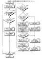
次に、実施例1に係る電子機器100の処理手順を説明する。図5は、実施例1に係る電子機器の処理手順を示すフローチャートである。図5に示すように、電子機器100は、タッチパネル120aに対する指の接触を受け付け、指IDに対応付けてタッチ座標を検出する(ステップS101)。 Next, a processing procedure of the
電子機器100は、検出タッチ座標がタッチパネル120aの無効化領域に存在するか否かを判定する(ステップS102)。電子機器100は、検出タッチ座標が無効化領域に存在する場合には(ステップS102;Yes)、タッチパネル120aに対する指の接触が最初の接触であるか否かを判定する(ステップS103)。 The
電子機器100は、タッチパネル120aに対する指の接触が最初の接触であるならば(ステップS103;Yes)、指IDに対応付けて検出タッチ座標をメモリ130に保存する(ステップS104)。これにより、検出タッチ座標が、無効化領域内の始点としてメモリ130に保存される。電子機器100は、上位処理部144に対する検出タッチ座標の出力を中止し(ステップS105)、処理をステップS118に移行する。電子機器100は、タッチパネル120aに対する指の接触が最初の接触でないならば(ステップS103;No)、ステップS104を省略し、処理をステップS105に移行する。 If the touch of the finger on the
一方、電子機器100は、検出タッチ座標がタッチパネル120aの無効化領域に存在しない場合には(ステップS102;No)、メモリ130に保存されている検出タッチ座標が初期値「−1(補正なし)」であるか否かを判定する(ステップS106)。電子機器100は、メモリ130に保存されている検出タッチ座標が初期値「−1(補正なし)」である場合には(ステップS106;Yes)、今回の検出タッチ座標を上位処理部144にそのまま出力し(ステップS107)、処理をステップS118に進める。一方、電子機器100は、メモリ130に保存されている検出タッチ座標が初期値「−1(補正なし)」でない場合には(ステップS106;No)、検出タッチ座標が無効化領域から有効化領域に移動したか否かを判定する(ステップS108)。 On the other hand, when the detected touch coordinates do not exist in the invalidated area of the
電子機器100は、検出タッチ座標が無効化領域から有効化領域に移動した場合には(ステップS108;Yes)、必要に応じて指IDを変換後ID:0に変換する(ステップS109)。電子機器100は、今回の検出タッチ座標をメモリ130に保存されている検出タッチ座標に補正する(ステップS110)。電子機器100は、補正後の検出タッチ座標をメモリ130に上書き保存する(ステップS111)。メモリ130に上書き保存された検出タッチ座標が、前回補正された検出タッチ座標となる。座標補正部143は、補正後の検出タッチ座標を上位処理部144に出力し(ステップS112)、処理をステップS118に移行する。このとき、電子機器100は、変換指IDが存在する場合には、変換指IDに対応づけて補正後の検出タッチ座標を上位処理部144に出力し、変換指IDが存在しない場合には、指IDに対応づけて補正後の検出タッチ座標を上位処理部144に出力する。 When the detected touch coordinates move from the invalidation area to the validation area (step S108; Yes), the
一方、電子機器100は、検出タッチ座標が無効化領域から有効化領域に移動していない場合、すなわち、検出タッチ座標が有効化領域内で移動した場合には(ステップS108;No)、以下の処理を行う。すなわち、電子機器100は、メモリ130に保存された検出タッチ座標、すなわち、前回補正された検出タッチ座標を用いて、今回の検出タッチ座標を補正する(ステップS113)。電子機器100は、補正後の検出タッチ座標と、前回補正された検出タッチ座標との間の距離を算出し(ステップS114)、算出した距離が所定の閾値以下であるか否かを判定する(ステップS115)。 On the other hand, when the detected touch coordinates have not moved from the invalidation area to the validation area, that is, when the detected touch coordinates have moved within the validation area (Step S108; No), the
電子機器100は、算出した距離が所定の閾値を超過するならば(ステップS115;No)、処理をステップS111に移行する。 If the calculated distance exceeds the predetermined threshold value (step S115; No), the
一方、電子機器100は、算出した距離が所定の閾値以下であるならば(ステップS115;Yes)、上位処理部144に対する補正後の検出タッチ座標の出力を中止する(ステップS116)。電子機器100は、メモリ130に保存されている変換後ID及びタッチ座標をクリアし、変換後ID及びタッチ座標に初期値を設定し(ステップS117)、処理をステップS107に移行する。 On the other hand, if the calculated distance is equal to or less than the predetermined threshold (step S115; Yes), the
電子機器100は、処理を終了するか否かを判定する(ステップS118)。電子機器100は、処理を継続する場合には(ステップS118;No)、処理をステップS101に戻す。一方、電子機器100は、処理を終了する場合には(ステップS118;Yes)、処理を終了する。 The
次に、実施例1に係る電子機器100の効果を説明する。電子機器100は、タッチ座標を検出し、検出タッチ座標が無効化領域に存在する場合に、検出タッチ座標をメモリ130に保存し、検出タッチ座標が有効化領域に移動した場合に、検出タッチ座標をメモリ130に保存された検出タッチ座標に補正する。このため、電子機器100は、タッチパネル120aにおいて無効化領域を始点とし有効化領域を終点とするスライド操作が行われた場合に、始点となるタッチ座標を用いてスライド操作を有効化することができる。結果として、実施例1の電子機器100によれば、始点となるタッチ座標が用いられない従来技術と比較して、タッチパネル120aにおいて操作を無効化する領域を始点とする操作が行われる場合の操作性を向上することができる。 Next, effects of the
また、実施例1の電子機器100は、検出タッチ座標が有効化領域内で移動した場合に、前回補正された検出タッチ座標を用いて、今回の検出タッチ座標を補正する。このため、実施例1の電子機器100は、過去の検出タッチ座標を考慮した現在の検出タッチ座標を取得することができる。結果として、実施例1の電子機器100によれば、タッチパネル120aにおいて操作を無効化する領域を始点とする操作が他の領域内で継続して行われる場合の操作性を向上することができる。 In addition, when the detected touch coordinates move within the validation area, the
また、実施例1の電子機器100は、検出タッチ座標が有効化領域内で移動した場合に、補正後の検出タッチ座標と、前回補正された検出タッチ座標との間の距離が所定の閾値以下であるか否かを判定する。電子機器100は、距離が所定の閾値を超過するならば、補正後の検出タッチ座標を上位処理部144に出力し、距離が所定の閾値以下であるならば、上位処理部144に対する補正後の検出タッチ座標の出力を中止する。このため、実施例1の電子機器100は、タッチパネル120aにおいて操作を無効化する領域を始点とする操作が他の領域内で継続して行われ、かつ、他の領域内での指の移動距離が減少した場合に、補正後の検出タッチ座標を用いた操作を中止することができる。 In addition, in the
なお、上述の説明では、電子機器100が、前回補正された検出タッチ座標と、今回の検出タッチ座標との平均値を求めることによって、補正後の検出タッチ座標を算出する例を示したが、開示技術はこれに限られない。例えば、電子機器100は、バネ特性等の物理法則を適用した所定の数式に対して、前回補正された検出タッチ座標と今回の検出タッチ座標とを代入することによって、補正後の検出タッチ座標を算出するようにしても良い。 In the above description, the example in which the
まず、実施例2に係る電子機器による動作の一例を説明する。図6は、実施例2に係る電子機器による動作の一例を説明する説明図である。図6の例では、電子機器に搭載されたタッチパネルの表面の端部領域に無効化領域R1が予め設定され、端部領域により囲まれる中央領域に有効化領域R2が予め設定されているものとする。 First, an example of an operation performed by the electronic apparatus according to the second embodiment will be described. FIG. 6 is an explanatory diagram illustrating an example of an operation performed by the electronic apparatus according to the second embodiment. In the example of FIG. 6, the invalidation area R1 is preset in the end area on the surface of the touch panel mounted on the electronic device, and the validation area R2 is preset in the center area surrounded by the end area. To do.
電子機器は、タッチパネルに対する接触位置の座標(以下「タッチ座標」という)を検出する。図6の例では、電子機器は、タッチパネルに対する指F1〜F3のタッチ座標をそれぞれ検出する。 The electronic device detects the coordinates of the contact position with respect to the touch panel (hereinafter referred to as “touch coordinates”). In the example of FIG. 6, the electronic device detects the touch coordinates of the fingers F1 to F3 on the touch panel.
電子機器は、検出されるタッチ座標がタッチパネルの無効化領域R1に存在する場合に、該タッチ座標を記憶装置に保存する。図6の例では、電子機器は、時刻「T0」に指F1のタッチ座標(5,100)が無効化領域R1に存在するので、指F1のタッチ座標(5,100)を記憶装置に保存する。また、図6の例では、電子機器は、指F2のタッチ座標(5,400)が無効化領域R1に存在するので、指F2のタッチ座標(5,400)を記憶装置に保存する。 When the detected touch coordinates exist in the invalidation region R1 of the touch panel, the electronic device stores the touch coordinates in the storage device. In the example of FIG. 6, the electronic device stores the touch coordinates (5, 100) of the finger F1 in the storage device because the touch coordinates (5, 100) of the finger F1 exist in the invalidation region R1 at time “T0”. To do. In the example of FIG. 6, the electronic device stores the touch coordinates (5,400) of the finger F2 in the storage device because the touch coordinates (5,400) of the finger F2 exist in the invalidation region R1.
なお、図6の例では、電子機器は、タッチ座標を用いた操作処理を行う上位の処理部に対して、無効化領域R1に存在する指F1,指F2のタッチ座標の出力を行わない。これにより、指F1,指F2のタッチ座標を用いた操作が無効化される。また、電子機器は、指F3のタッチ座標(280,400)が有効化領域R2に存在するので、指F3のタッチ座標の保存を行わず、タッチ座標を用いた操作処理を行う上位の処理部に指F3のタッチ座標をそのまま出力する。これにより、指F3のタッチ座標を用いた操作が有効化される。 In the example of FIG. 6, the electronic device does not output the touch coordinates of the finger F1 and the finger F2 existing in the invalidation region R1 to the upper processing unit that performs the operation process using the touch coordinates. Thereby, the operation using the touch coordinates of the finger F1 and the finger F2 is invalidated. In addition, since the touch coordinates (280, 400) of the finger F3 are present in the validation region R2, the electronic device does not store the touch coordinates of the finger F3 and performs an operation process using the touch coordinates. The touch coordinates of the finger F3 are output as they are. Thereby, the operation using the touch coordinates of the finger F3 is validated.
続いて、電子機器は、検出されるタッチ座標がタッチパネルの無効化領域R1から有効化領域R2に移動した場合に、記憶装置に保存されたタッチ座標と検出されるタッチ座標との差分を算出するとともに該タッチ座標を記憶装置に保存されたタッチ座標に補正する。すなわち、電子機器は、タッチパネルに対する指の接触位置が無効化領域R1を超えてから、最初に検出されるタッチ座標と、無効化領域R1内の始点として記憶装置に保存されたタッチ座標との差分を算出する。さらに、電子機器は、最初に検出されるタッチ座標を、無効化領域R1内の始点として記憶装置に保存されたタッチ座標に補正する。図6の例では、時刻「T1」に指F1のタッチ座標が無効化領域R1から有効化領域R2の座標(125,100)に移動している。このため、電子機器は、記憶装置に保存された指F1のタッチ座標(5,100)と、今回検出される指F1のタッチ座標(125,100)との差分(ΔX,ΔY)=(120,0)を算出する。さらに、電子機器は、今回検出される指F1のタッチ座標(125,100)を記憶装置に保存された指F1のタッチ座標(5,100)に補正する。補正後の指F1のタッチ座標は、タッチ座標を用いた操作処理を行う上位の処理部に出力される。これにより、補正後の指F1のタッチ座標を用いた操作が有効化される。 Subsequently, when the detected touch coordinates move from the invalidation area R1 to the validation area R2 of the touch panel, the electronic device calculates a difference between the touch coordinates stored in the storage device and the detected touch coordinates. At the same time, the touch coordinates are corrected to the touch coordinates stored in the storage device. That is, the electronic device detects the difference between the touch coordinates detected first after the finger touch position on the touch panel exceeds the invalidation area R1 and the touch coordinates stored in the storage device as the start point in the invalidation area R1. Is calculated. Further, the electronic device corrects the touch coordinates detected first to the touch coordinates stored in the storage device as the start point in the invalidation region R1. In the example of FIG. 6, the touch coordinates of the finger F1 are moved from the invalidation area R1 to the coordinates (125, 100) of the validation area R2 at time “T1”. Therefore, the electronic device has a difference (ΔX, ΔY) = (120) between the touch coordinates (5, 100) of the finger F1 stored in the storage device and the touch coordinates (125, 100) of the finger F1 detected this time. , 0). Further, the electronic device corrects the touch coordinates (125, 100) of the finger F1 detected this time to the touch coordinates (5, 100) of the finger F1 stored in the storage device. The corrected touch coordinates of the finger F1 are output to an upper processing unit that performs an operation process using the touch coordinates. Thereby, the operation using the touch coordinates of the finger F1 after correction is validated.
なお、図6の例では、電子機器は、指F2のタッチ座標が無効化領域R1から移動していないので、タッチ座標を用いた操作処理を行う上位の処理部に指F2のタッチ座標の出力を行わない。これにより、指F2のタッチ座標を用いた操作が継続的に無効化される。 In the example of FIG. 6, since the touch coordinate of the finger F2 has not moved from the invalidation region R1, the electronic device outputs the touch coordinate of the finger F2 to a higher-level processing unit that performs an operation process using the touch coordinate. Do not do. Thereby, the operation using the touch coordinates of the finger F2 is continuously invalidated.
続いて、電子機器は、タッチ座標を補正した後に検出されるタッチ座標が有効化領域R2内で移動した場合に、算出済みの差分を用いて、今回検出されたタッチ座標を補正する。図6の例では、電子機器は、時刻「T2」に指F1のタッチ座標が有効化領域R2内で座標(245,100)に移動しているので、差分(ΔX,ΔY)=(120,0)を用いて、今回検出された指F1のタッチ座標(245,100)を補正する。ここでは、一例として、電子機器は、差分(ΔX,ΔY)=(120,0)を減少させ、減少させた差分(ΔX,ΔY)=(95,0)を今回検出された指F1のタッチ座標から減算することによって、補正後の指F1のタッチ座標(150,100)を算出する。補正後の指F1のタッチ座標は、タッチ座標を用いた操作処理を行う上位の処理部に出力される。これにより、補正後の指F1のタッチ座標を用いた操作が継続的に有効化される。また、図6の例では、電子機器は、時刻「T3」に指F1のタッチ座標が有効化領域R2内で座標(325,100)に移動しているので、差分(ΔX,ΔY)=(95,0)を用いて、今回検出された指F1のタッチ座標(325,100)を補正する。ここでは、一例として、電子機器は、差分(ΔX,ΔY)=(95,0)を減少させ、減少させた差分(ΔX,ΔY)=(74,0)を今回検出された指F1のタッチ座標から減算することによって、補正後の指F1のタッチ座標(251,100)を算出する。補正後の指F1のタッチ座標は、タッチ座標を用いた操作処理を行う上位の処理部に出力される。これにより、補正後の指F1のタッチ座標を用いた操作が継続的に有効化される。 Subsequently, when the touch coordinates detected after correcting the touch coordinates move within the validation region R2, the electronic device corrects the touch coordinates detected this time using the calculated difference. In the example of FIG. 6, since the touch coordinates of the finger F1 are moved to the coordinates (245, 100) in the validation region R2 at the time “T2,” the electronic device has a difference (ΔX, ΔY) = (120, 0) is used to correct the touch coordinates (245, 100) of the finger F1 detected this time. Here, as an example, the electronic device reduces the difference (ΔX, ΔY) = (120, 0), and touches the finger F1 detected this time with the reduced difference (ΔX, ΔY) = (95, 0). By subtracting from the coordinates, the corrected touch coordinates (150, 100) of the finger F1 are calculated. The corrected touch coordinates of the finger F1 are output to an upper processing unit that performs an operation process using the touch coordinates. Thereby, the operation using the touch coordinates of the corrected finger F1 is continuously enabled. In the example of FIG. 6, since the electronic device moves the touch coordinate of the finger F1 to the coordinate (325, 100) in the validation region R2 at time “T3”, the difference (ΔX, ΔY) = ( 95,0) is used to correct the touch coordinates (325, 100) of the finger F1 detected this time. Here, as an example, the electronic device reduces the difference (ΔX, ΔY) = (95, 0), and touches the finger F1 detected this time with the reduced difference (ΔX, ΔY) = (74, 0). By subtracting from the coordinates, the corrected touch coordinates (251, 100) of the finger F1 are calculated. The corrected touch coordinates of the finger F1 are output to an upper processing unit that performs an operation process using the touch coordinates. Thereby, the operation using the touch coordinates of the corrected finger F1 is continuously enabled.
このように、実施例2の電子機器は、検出されるタッチ座標が有効化領域R2に移動した場合に、記憶装置に保存されたタッチ座標と検出されるタッチ座標との差分を算出するとともに該タッチ座標を記憶装置に保存されたタッチ座標に補正する。そして、実施例2の電子機器は、タッチ座標を補正した後に検出されるタッチ座標が有効化領域R2内で移動した場合に、算出済みの差分を用いて、今回検出されたタッチ座標を補正する。このため、実施例2の電子機器は、タッチパネルにおいて無効化領域を始点とする操作が有効化領域内で継続して行われた場合の操作性をより向上することができる。 As described above, the electronic device according to the second embodiment calculates the difference between the touch coordinates stored in the storage device and the detected touch coordinates when the detected touch coordinates move to the validation area R2. The touch coordinates are corrected to the touch coordinates stored in the storage device. Then, when the touch coordinates detected after correcting the touch coordinates move within the validation region R2, the electronic device according to the second embodiment corrects the touch coordinates detected this time using the calculated difference. . For this reason, the electronic device of Example 2 can further improve the operability when the operation starting from the invalidation area is continuously performed in the validation area on the touch panel.
次に、実施例2に係る電子機器200の構成例を説明する。図7は、実施例2に係る電子機器の構成例を示す図である。図7に示すように、実施例2に係る電子機器200は、LCD110、タッチパネル120a、タッチコントロールIC120b、メモリ230およびCPU240を有する。LCD110、タッチパネル120a、タッチコントロールIC120b、メモリ230およびCPU240は、バス150によって相互に接続される。 Next, a configuration example of the electronic device 200 according to the second embodiment will be described. FIG. 7 is a diagram illustrating a configuration example of the electronic apparatus according to the second embodiment. As illustrated in FIG. 7, the electronic device 200 according to the second embodiment includes an
LCD110、タッチパネル120aおよびタッチコントロールIC120bに関する説明は、図2に示すLCD110、タッチパネル120aおよびタッチコントロールIC120bに関する説明と同様であるため、ここでは同一の符号を付して説明を省略する。 The description regarding the
メモリ230は、各種の情報を記憶する記憶装置である。後述するように、特に、メモリ230は、CPU240の制御命令に応じて、検出タッチ座標の初回の補正に用いられるタッチ座標と、検出タッチ座標の2回目以降の補正に用いられる差分を記憶する。図8は、実施例2に係るメモリのデータ構造の一例を示す図である。図8に示すように、メモリ230は、指ID、変換指ID、タッチ座標および差分といった項目を対応付けて記憶する。 The
指IDは、タッチパネル120aによって指に割り当てられた、指を識別するための識別子である。例えば、タッチパネル120aの表面に接触した1本目の指には、指ID:0が割り当てられ、タッチパネル120aの表面に接触した2本目以降の指には、指IDとして1以上の整数が昇順で割り当てられる。 The finger ID is an identifier for identifying a finger assigned to the finger by the
変換指IDは、指IDで識別される指がタッチパネル120aの無効化領域から有効化領域に移動した場合に、移動した指の指IDが変換されて得られる識別子である。例えば、指IDで識別される指がタッチパネル120aの無効化領域から有効化領域に移動した場合であり、かつ、移動した指の指IDが「0」以外である場合に、指IDが、タッチパネル120aの表面に接触した1本目の指を表す「0」に変換される。なお、変換指IDには、初期値として「−1(変換なし)」が格納される。 The conversion finger ID is an identifier obtained by converting the finger ID of the moved finger when the finger identified by the finger ID moves from the invalidation area of the
タッチ座標(X1st,Y1st)は、指IDで識別される指に対応する検出タッチ座標の初回の補正に用いられるタッチ座標を格納する。例えば、タッチ座標(X1st,Y1st)には、無効化領域に存在する指のタッチ座標が格納される。なお、タッチ座標(X1st,Y1st)には、初期値として「−1(補正なし)」が格納される。 The touch coordinates (X1st, Y1st) store the touch coordinates used for the first correction of the detected touch coordinates corresponding to the finger identified by the finger ID. For example, the touch coordinates (X1st, Y1st) store the touch coordinates of the finger existing in the invalidation area. In the touch coordinates (X1st, Y1st), “−1 (no correction)” is stored as an initial value.
差分(ΔX,ΔY)は、検出タッチ座標の2回目以降の補正に用いられる差分を格納する。例えば、差分(ΔX,ΔY)には、無効化領域に存在する指のタッチ座標と、無効化領域から有効化領域に移動した指のタッチ座標との差分が格納される。なお、差分(ΔX,ΔY)には、初期値として「0(補正なし)」が格納される。 The difference (ΔX, ΔY) stores a difference used for the second and subsequent corrections of the detected touch coordinates. For example, the difference (ΔX, ΔY) stores the difference between the touch coordinates of the finger existing in the invalidation area and the touch coordinates of the finger moved from the invalidation area to the validation area. The difference (ΔX, ΔY) stores “0 (no correction)” as an initial value.
図8の1行目は、指ID:0で識別される指が無効化領域に存在するので、指IDが変換されず、かつ、無効化領域に存在する指のタッチ座標(5,400)が格納されていることを示す。図8の2行目は、指ID:1で識別される指がタッチパネル120aの無効化領域から有効化領域に移動したので、指ID:1が変換指ID:0に変換され、かつ検出タッチ座標の初回の補正に用いられるタッチ座標(5,100)が格納されていることを示す。さらに、図8の2行目は、検出タッチ座標の2回目以降の補正に用いられる差分(120,0)が格納されていることを示す。図3の3行目は、指ID:2で識別される指がタッチパネル120aの有効化領域に存在するので、指ID:2が変換指ID:1に変換され、かつタッチ座標が補正されないことを示す。 In the first line of FIG. 8, since the finger identified by the finger ID: 0 exists in the invalidation area, the finger ID is not converted and the touch coordinates (5,400) of the finger existing in the invalidation area Is stored. The second row in FIG. 8 shows that the finger identified by the finger ID: 1 has moved from the invalidation area of the
CPU240は、タッチコントロールIC120bから取得する検出タッチ座標がタッチパネル120aの無効化領域から有効化領域に移動した場合に、検出タッチ座標を補正する装置である。CPU240は、補正後の検出タッチ座標をタッチ座標を用いた操作処理を行う上位処理部に出力する。 The
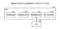
ここで、CPU240の機能構成の一例について説明する。図9は、実施例2に係るCPUの機能構成の一例を示すブロック図である。図9に示すように、CPU240は、座標取得部241、座標判定部242、座標補正部243及び上位処理部244を有する。 Here, an example of a functional configuration of the
座標取得部241は、指IDに対応づけられた検出タッチ座標をタッチコントロールIC120bから取得する。座標取得部241は、検出タッチ座標を取得する度に、取得した検出タッチ座標を座標判定部242に出力する。 The coordinate
座標判定部242は、検出タッチ座標がタッチパネル120aの無効化領域に存在するか否かを判定し、判定の結果及び検出タッチ座標を座標補正部243に出力する。 The coordinate
座標補正部243は、座標判定部242による判定の結果に応じて検出タッチ座標を補正する。座標補正部243は、補正部の一例である。 The coordinate
ここで、検出タッチ座標の補正処理の詳細を説明する。座標補正部243は、座標判定部242による判定の結果、検出タッチ座標がタッチパネル120aの無効化領域に存在する場合に、指IDに対応づけて検出タッチ座標をメモリ230に保存する。 Here, details of the correction processing of the detected touch coordinates will be described. The coordinate correcting
一方、座標補正部243は、座標判定部242による判定の結果、検出タッチ座標がタッチパネル120aの無効化領域に存在しない場合に、検出タッチ座標が無効化領域から有効化領域に移動したか否かを判定する。座標補正部243は、検出タッチ座標が無効化領域から有効化領域に移動した場合に、必要に応じて指IDを変換指ID:0に変換し、メモリ230に保存されている検出タッチ座標と、今回の検出タッチ座標との差分を算出する。さらに、メモリ230は、今回の検出タッチ座標をメモリ230に保存されている検出タッチ座標に補正する。つまり、座標補正部243は、タッチパネル120aに対する指の接触位置が無効化領域を超えてから、最初に検出される今回の検出タッチ座標を、無効化領域内の始点としてメモリ230に保存されている検出タッチ座標に補正する。 On the other hand, as a result of the determination by the coordinate
続いて、座標補正部243は、算出した差分を指IDに対応づけてメモリ230に保存する。メモリ230に保存された差分が、検出タッチ座標の2回目以降の補正に用いられる差分(補正量)となる。座標補正部243は、補正後の検出タッチ座標を上位処理部244に出力する。このとき、座標補正部243は、変換指IDが存在する場合には、変換指IDに対応づけて補正後の検出タッチ座標を上位処理部244に出力し、変換指IDが存在しない場合には、指IDに対応づけて補正後の検出タッチ座標を上位処理部244に出力する。 Subsequently, the coordinate
一方、座標補正部243は、検出タッチ座標が無効化領域から有効化領域に移動していない場合、すなわち、検出タッチ座標が有効化領域内で移動した場合には、以下の処理を行う。座標補正部243は、メモリ230に保存された差分を用いて、今回の検出タッチ座標を補正する。詳細には、座標補正部243は、検出タッチ座標が有効化領域内で移動する度に、メモリ230に保存された差分を非線形的に減少させ、減少させた差分を今回の検出タッチ座標から加算又は減算することによって、補正後の検出タッチ座標を算出する。例えば、座標補正部243は、下記の式(2a),(2b)を用いて、補正後の検出タッチ座標を算出する。 On the other hand, when the detected touch coordinates have not moved from the invalidation area to the validation area, that is, when the detected touch coordinates have moved within the validation area, the coordinate
Xcur=Xorg±ΔX ・・・ (2a) Xcur = Xorg ± ΔX (2a)
Ycur=Yorg±ΔY ・・・ (2b) Ycur = Yorg ± ΔY (2b)
式(2a),(2b)において、検出タッチ座標が有効化領域内でX軸又はY軸の正方向へ移動した場合には、「−」が採用され、検出タッチ座標が有効化領域内でX軸又はY軸の負方向へ移動した場合には、「+」が採用される。式(2a),(2b)において、(Xcur,Ycur)は、補正後の検出タッチ座標である。(Xorg,Yorg)は、座標取得部241から取得される今回の検出タッチ座標である。(ΔX,ΔY)は、検出タッチ座標が有効化領域内で移動する度に、メモリ230に保存された差分を非線形的に減少させることで得られる差分である。(ΔX,ΔY)は、例えば、以下の式(3a),(3b)を用いて求められる。 In the expressions (2a) and (2b), when the detected touch coordinate moves in the positive direction of the X axis or the Y axis within the validation area, “-” is adopted, and the detected touch coordinate is within the validation area. When moving in the negative direction of the X axis or the Y axis, “+” is adopted. In equations (2a) and (2b), (Xcur, Ycur) is the detected touch coordinates after correction. (Xorg, Yorg) is the current detected touch coordinates acquired from the coordinate
ΔX=ΔX1st{1−0.05(n−1)} ・・・ (3a)ΔX = ΔX1st{ 1-0.05(n−1)} (3a)
ΔY=ΔY1st{1−0.05(n−1)} ・・・ (3b)ΔY = ΔY1st{ 1-0.05(n−1)} (3b)
式(3a),(3b)において、nは、検出タッチ座標が有効化領域内で移動した回数である。(ΔX1st,ΔY1st)は、検出タッチ座標が無効化領域から有効化領域に移動した場合に、メモリ230に最初に保存された差分、すなわち、無効化領域に存在する検出タッチ座標と、無効化領域から有効化領域に移動した検出タッチ座標との差分である。差分ΔXとnとの関係の一例を図10に示す。 In equations (3a) and (3b), n is the number of times the detected touch coordinates have moved within the validation area. (ΔX1st, ΔY1st) is the difference first stored in the
図10は、差分ΔXとnとの関係の一例を示す図である。図10の例では、ΔX1stが、120であるものとする。図10に示すように、差分ΔXは、検出タッチ座標が有効化領域内で移動する度に、非線形的に減少する。 FIG. 10 is a diagram illustrating an example of the relationship between the difference ΔX and n. In the example of FIG. 10, ΔX1st is assumed to be 120. As shown in FIG. 10, the difference ΔX decreases nonlinearly every time the detected touch coordinates move within the activated area.
そして、座標補正部243は、減少させた差分が所定の閾値以下であるか否かを判定する。座標補正部243は、減少させた差分が所定の閾値を超過するならば、減少させた差分をメモリ230に上書き保存し、補正後の検出タッチ座標を上位処理部244に出力する。このとき、座標補正部243は、変換指IDが存在する場合には、変換指IDに対応づけて補正後の検出タッチ座標を上位処理部244に出力し、変換指IDが存在しない場合には、指IDに対応づけて補正後の検出タッチ座標を上位処理部244に出力する。 Then, the coordinate
一方、座標補正部243は、減少させた差分が所定の閾値以下であるならば、補正後の検出タッチ座標の出力を中止するとともに、座標取得部141から取得される今回の検出タッチ座標をそのまま上位処理部244に出力する。このとき、座標補正部143は、指IDに対応づけて今回の検出タッチ座標を上位処理部244に出力する。 On the other hand, if the reduced difference is equal to or smaller than the predetermined threshold value, the coordinate
上位処理部244は、座標補正部243から入力される検出タッチ座標を用いてスライド操作等の所定の操作処理を行う。 The
次に、実施例2に係る電子機器200の処理手順を説明する。図11は、実施例2に係る電子機器の処理手順を示すフローチャートである。図11に示すように、電子機器200は、タッチパネル120aに対する指の接触を受け付け、指IDに対応付けてタッチ座標を検出する(ステップS201)。 Next, a processing procedure of the electronic device 200 according to the second embodiment will be described. FIG. 11 is a flowchart illustrating the processing procedure of the electronic apparatus according to the second embodiment. As illustrated in FIG. 11, the electronic device 200 receives a finger contact with the
電子機器200は、検出タッチ座標がタッチパネル120aの無効化領域に存在するか否かを判定する(ステップS202)。電子機器200は、検出タッチ座標が無効化領域に存在する場合には(ステップS202;Yes)、タッチパネル120aに対する指の接触が最初の接触であるか否かを判定する(ステップS203)。 The electronic device 200 determines whether or not the detected touch coordinates exist in the invalidation area of the
電子機器100は、タッチパネル120aに対する指の接触が最初の接触であるならば(ステップS203;Yes)、指IDに対応付けて検出タッチ座標をメモリ230に保存する(ステップS204)。これにより、検出タッチ座標が、無効化領域内の始点としてメモリ230に保存される。電子機器200は、上位処理部244に対する検出タッチ座標の出力を中止し(ステップS205)、処理をステップS219に移行する。電子機器200は、タッチパネル120aに対する指の接触が最初の接触でないならば(ステップS203;No)、ステップS204を省略し、処理をステップS205に移行する。 If the touch of the finger on the
一方、電子機器200は、検出タッチ座標がタッチパネル120aの無効化領域に存在しない場合には(ステップS202;No)、メモリ230に保存されている検出タッチ座標が初期値「−1(補正なし)」であるか否かを判定する(ステップS206)。電子機器100は、メモリ230に保存されている検出タッチ座標が初期値「−1(補正なし)」である場合には(ステップS206;Yes)、今回の検出タッチ座標を上位処理部244にそのまま出力し(ステップS207)、処理をステップS219に進める。一方、電子機器200は、メモリ230に保存されている検出タッチ座標が初期値「−1(補正なし)」でない場合には(ステップS206;No)、検出タッチ座標が無効化領域から有効化領域に移動したか否かを判定する(ステップS208)。 On the other hand, when the detected touch coordinates do not exist in the invalidation area of the
電子機器200は、検出タッチ座標が無効化領域から有効化領域に移動した場合には(ステップS208;Yes)、必要に応じて指IDを変換後ID:0に変換する(ステップS209)。電子機器200は、メモリ230に保存されている検出タッチ座標と、今回の検出タッチ座標との差分を算出し(ステップS210)、今回の検出タッチ座標をメモリ230に保存されている検出タッチ座標に補正する(ステップS211)。 When the detected touch coordinates move from the invalidation area to the validation area (step S208; Yes), the electronic device 200 converts the finger ID into post-conversion ID: 0 as necessary (step S209). The electronic device 200 calculates a difference between the detected touch coordinates stored in the
続いて、電子機器200は、算出した差分を指IDに対応付けてメモリ230に保存する(ステップS212)。メモリ230に保存された差分が、検出タッチ座標の2回目以降の補正に用いられる差分(補正量)となる。座標補正部243は、補正後の検出タッチ座標を上位処理部244に出力し(ステップS213)、処理をステップS219に移行する。このとき、電子機器200は、変換指IDが存在する場合には、変換指IDに対応づけて補正後の検出タッチ座標を上位処理部244に出力し、変換指IDが存在しない場合には、指IDに対応づけて補正後の検出タッチ座標を上位処理部244に出力する。 Subsequently, the electronic device 200 stores the calculated difference in the
一方、電子機器200は、検出タッチ座標が無効化領域から有効化領域に移動していない場合、すなわち、検出タッチ座標が有効化領域内で移動した場合には(ステップS208;No)、以下の処理を行う。すなわち、電子機器200は、メモリ230に保存された差分を減少させる(ステップS214)。電子機器200は、減少させた差分を今回の検出タッチ座標から加算又は減算することによって、補正後の検出タッチ座標を算出する(ステップS215)。電子機器200は、減少させた差分が所定の閾値以下であるか否かを判定する(ステップS216)。 On the other hand, when the detected touch coordinates are not moved from the invalidation area to the validation area, that is, when the detected touch coordinates are moved within the validation area (step S208; No), the electronic device 200 performs the following. Process. In other words, the electronic device 200 decreases the difference stored in the memory 230 (step S214). The electronic device 200 calculates the corrected detected touch coordinates by adding or subtracting the reduced difference from the current detected touch coordinates (step S215). The electronic device 200 determines whether or not the reduced difference is equal to or less than a predetermined threshold (step S216).
電子機器200は、減少させた差分が所定の閾値を超過するならば(ステップS216;No)、処理をステップS212に移行する。 If the reduced difference exceeds a predetermined threshold (step S216; No), the electronic device 200 moves the process to step S212.
一方、電子機器200は、減少させた差分が所定の閾値以下であるならば(ステップS216;Yes)、上位処理部244に対する補正後の検出タッチ座標の出力を中止する(ステップS217)。電子機器200は、メモリ230に保存されている変換後ID及び差分をクリアし、変換後ID及び差分に初期値を設定し(ステップS218)、処理をステップS207に移行する。 On the other hand, if the reduced difference is equal to or smaller than the predetermined threshold (step S216; Yes), the electronic device 200 stops outputting the corrected touch coordinate to the upper processing unit 244 (step S217). The electronic device 200 clears the post-conversion ID and difference stored in the
電子機器200は、処理を終了するか否かを判定する(ステップS219)。電子機器200は、処理を継続する場合には(ステップS219;No)、処理をステップS201に戻す。一方、電子機器200は、処理を終了する場合には(ステップS219;Yes)、処理を終了する。 The electronic device 200 determines whether or not to end the process (step S219). When the electronic device 200 continues the process (step S219; No), the electronic apparatus 200 returns the process to step S201. On the other hand, when the electronic device 200 ends the process (step S219; Yes), the process ends.
次に、実施例2に係る電子機器200の効果を説明する。電子機器200は、検出タッチ座標が有効化領域に移動した場合に、メモリ230に保存された検出タッチ座標と今回の検出タッチ座標との差分を算出するとともに今回の検出タッチ座標をメモリ230に保存されたタッチ座標に補正する。そして、電子機器200は、検出タッチ座標が有効化領域内で移動した場合に、算出済みの差分を用いて、今回の検出タッチ座標を補正する。このため、実施例2に係る電子機器200によれば、タッチパネルにおいて無効化領域を始点とする操作が有効化領域内で継続して行われた場合の操作性をより向上することができる。 Next, effects of the electronic device 200 according to the second embodiment will be described. When the detected touch coordinates move to the validation area, the electronic device 200 calculates a difference between the detected touch coordinates stored in the
また、実施例2の電子機器200は、検出タッチ座標が有効化領域内で移動する度に、算出済みの差分を減少させ、減少させた差分を今回の検出タッチ座標から減算することによって、今回の検出タッチ座標を補正する。このため、実施例2に係る電子機器200によれば、検出タッチ座標と補正後の検出タッチ座標とを漸次的に近づけることが可能となる。 In addition, the electronic device 200 according to the second embodiment reduces the calculated difference each time the detected touch coordinates move within the validation area, and subtracts the decreased difference from the current detected touch coordinates, The detected touch coordinates are corrected. For this reason, according to the electronic device 200 according to the second embodiment, the detected touch coordinates and the corrected detected touch coordinates can be gradually brought closer to each other.
また、実施例2の電子機器200は、減少させた差分が所定の閾値以下であるか否かを判定する。電子機器200は、減少させた差分が所定の閾値を超過するならば、補正後の検出タッチ座標を上位処理部244に出力し、減少させた差分が所定の閾値以下であるならば、上位処理部244に対する補正後の検出タッチ座標の出力を中止する。このため、実施例2の電子機器200は、補正後の検出タッチ座標を用いた操作を適切に中止することができる。 Also, the electronic device 200 according to the second embodiment determines whether or not the reduced difference is equal to or less than a predetermined threshold value. If the reduced difference exceeds a predetermined threshold, the electronic device 200 outputs the detected touch coordinates after correction to the
[他の実施例]
上記の実施例1、2における各処理は、各処理に対応する座標入力プログラムをCPU140,240に実行させることによって実現してもよい。例えば、上記の実施例1、2における各処理に対応する座標入力プログラムがメモリ130,230に記憶され、座標入力プログラムがCPU140,240によってメモリ130,230から読み出されて実行されてもよい。[Other embodiments]
Each process in the first and second embodiments may be realized by causing the
100、200 電子機器
120a タッチパネル
120b タッチコントロールIC
130、230 メモリ
140、240 CPU
141、241 座標取得部
143、243 座標補正部100, 200
130, 230
141, 241 Coordinate
Claims (7)
Translated fromJapanese前記検出部によって検出される座標が前記タッチパネルにおいて該座標を用いた操作を無効化する領域である無効化領域に存在する場合に、該座標を記憶装置に保存し、前記検出部によって検出される座標が前記無効化領域から前記操作を有効化する他の領域に移動した場合に、前記検出部によって前記他の領域において最初に検出される座標を前記記憶装置に保存された前記座標に補正し、補正後の座標を前記操作の始点として出力して前記操作を有効化させる補正部と
を備えたことを特徴とする電子機器。A detection unit for detecting coordinates of a touch position on the touch panel;
When coordinates detected by the detection unit exist in an invalidation area that is an area for invalidating an operation using the coordinates on the touch panel, the coordinates are stored in a storage device and detected by the detection unit When the coordinates move from the invalidation area to another area that validates the operation, the coordinatesfirst detected in the other area by the detection unit are correctedto the coordinates stored in the storage device. An electronic devicecomprising: a correction unitthat outputs the corrected coordinates as a starting point of the operation and validates the operation .
前記座標を補正した後に前記検出部によって検出される座標が前記他の領域内で移動した場合に、前回補正された座標を用いて、前記検出部によって検出される座標を補正することを特徴とする請求項1に記載の電子機器。The correction unit is
When the coordinates detected by the detection unit after correcting the coordinates move in the other region, the coordinates detected by the detection unit are corrected using the previously corrected coordinates. The electronic device according to claim 1.
前記座標を補正した後に前記検出部によって検出される座標が前記他の領域内で移動した場合に、前記検出部によって検出される座標を今回補正することで得られる座標と、前回補正された座標との間の距離が所定の閾値以下であるか否かを判定し、該距離が前記所定の閾値を超過するならば、前記検出部によって検出される座標の補正を実行し、該距離が前記所定の閾値以下であるならば、前記検出部によって検出される座標の補正を中止することを特徴とする請求項2に記載の電子機器。The correction unit is
When the coordinates detected by the detecting unit after correcting the coordinates are moved in the other area, the coordinates obtained by correcting the coordinates detected by the detecting unit this time and the previously corrected coordinates Whether or not the distance between the two is less than or equal to a predetermined threshold, and if the distance exceeds the predetermined threshold, correction of the coordinates detected by the detection unit is performed, and the distance is The electronic apparatus according to claim 2, wherein correction of coordinates detected by the detection unit is stopped if the value is equal to or less than a predetermined threshold.
前記検出部によって検出される座標が前記無効化領域から前記他の領域に移動した場合に、前記記憶装置に保存された前記座標と前記検出部によって検出される座標との差分を算出するとともに該座標を前記記憶装置に保存された前記座標に補正し、
前記座標を補正した後に前記検出部によって検出される座標が前記他の領域内で移動した場合に、前記差分を用いて、前記検出部によって検出される座標を補正することを特徴とする請求項1に記載の電子機器。The correction unit is
When the coordinates detected by the detection unit move from the invalidation area to the other area, the difference between the coordinates stored in the storage device and the coordinates detected by the detection unit is calculated and the Correct the coordinates to the coordinates stored in the storage device,
The coordinate detected by the detection unit is corrected using the difference when the coordinate detected by the detection unit moves in the other region after correcting the coordinate. 1. The electronic device according to 1.
前記検出部によって検出される座標が前記他の領域内で移動する度に、前記差分を減少させ、減少させた前記差分を前記検出部によって検出される座標から減算することによって、前記検出部によって検出される座標を補正することを特徴とする請求項4に記載の電子機器。The correction unit is
Each time the coordinates detected by the detection unit move in the other region, the difference is decreased, and the detected difference is subtracted from the coordinates detected by the detection unit by the detection unit. The electronic device according to claim 4, wherein the detected coordinates are corrected.
減少させた前記差分が所定の閾値以下であるか否かを判定し、減少させた前記差分が前記所定の閾値を超過するならば、前記検出部によって検出される座標の補正を実行し、減少させた前記差分が前記所定の閾値以下であるならば、前記検出部によって検出される座標の補正を中止することを特徴とする請求項5に記載の電子機器。The correction unit is
It is determined whether or not the reduced difference is equal to or less than a predetermined threshold value. If the reduced difference exceeds the predetermined threshold value, correction of the coordinates detected by the detection unit is performed, and the decrease is performed. 6. The electronic apparatus according to claim 5, wherein if the difference made is equal to or less than the predetermined threshold, correction of coordinates detected by the detection unit is stopped.
タッチパネルに対する接触位置の座標を検出し、
検出される座標が前記タッチパネルにおいて該座標を用いた操作を無効化する領域である無効化領域に存在する場合に、該座標を記憶装置に保存し、検出される座標が前記無効化領域から前記操作を有効化する他の領域に移動した場合に、前記他の領域において最初に検出される座標を前記記憶装置に保存された前記座標に補正し、補正後の座標を前記操作の始点として出力して前記操作を有効化させる
処理を実行させることを特徴とする座標入力プログラム。On the computer,
Detect the coordinates of the touch position on the touch panel,
When the detected coordinates exist in an invalidation area that is an area for invalidating an operation using the coordinates on the touch panel, the coordinates are stored in a storage device, and the detected coordinates are stored in the invalidation area from the invalidation area. When moving to another area to validate the operation, the coordinatesfirst detected in the other area are correctedto the coordinates stored in the storage device,and the corrected coordinates are output as the start point of the operation. And executinga processfor enabling the operation .
Priority Applications (1)
| Application Number | Priority Date | Filing Date | Title |
|---|---|---|---|
| JP2013181606AJP6221527B2 (en) | 2013-09-02 | 2013-09-02 | Electronic equipment and coordinate input program |
Applications Claiming Priority (1)
| Application Number | Priority Date | Filing Date | Title |
|---|---|---|---|
| JP2013181606AJP6221527B2 (en) | 2013-09-02 | 2013-09-02 | Electronic equipment and coordinate input program |
Publications (2)
| Publication Number | Publication Date |
|---|---|
| JP2015049758A JP2015049758A (en) | 2015-03-16 |
| JP6221527B2true JP6221527B2 (en) | 2017-11-01 |
Family
ID=52699705
Family Applications (1)
| Application Number | Title | Priority Date | Filing Date |
|---|---|---|---|
| JP2013181606AExpired - Fee RelatedJP6221527B2 (en) | 2013-09-02 | 2013-09-02 | Electronic equipment and coordinate input program |
Country Status (1)
| Country | Link |
|---|---|
| JP (1) | JP6221527B2 (en) |
Families Citing this family (2)
| Publication number | Priority date | Publication date | Assignee | Title |
|---|---|---|---|---|
| CN105353906B (en)* | 2015-10-21 | 2018-08-28 | 业成光电(深圳)有限公司 | Trajectory predictions system and trajectory predictions method |
| JP2018010541A (en)* | 2016-07-14 | 2018-01-18 | 望月 貴里子 | User interface |
Family Cites Families (8)
| Publication number | Priority date | Publication date | Assignee | Title |
|---|---|---|---|---|
| JP3866833B2 (en)* | 1997-06-04 | 2007-01-10 | Dowaホールディングス株式会社 | Method and apparatus for correcting detection position of position detection object and touch panel device |
| US20090174679A1 (en)* | 2008-01-04 | 2009-07-09 | Wayne Carl Westerman | Selective Rejection of Touch Contacts in an Edge Region of a Touch Surface |
| JP2011100282A (en)* | 2009-11-05 | 2011-05-19 | Seiko Epson Corp | Display device and program |
| KR20130005296A (en)* | 2010-09-24 | 2013-01-15 | 큐엔엑스 소프트웨어 시스템즈 리미티드 | Portable electronic device and method of controlling same |
| CN103492986B (en)* | 2011-02-16 | 2017-08-15 | 日本电气株式会社 | Input device, input method and recording medium |
| JP5857465B2 (en)* | 2011-06-16 | 2016-02-10 | ソニー株式会社 | Information processing apparatus, information processing method, and program |
| JP5372091B2 (en)* | 2011-09-15 | 2013-12-18 | 株式会社ワコム | Electronic device and display screen control method for electronic device |
| JP5497722B2 (en)* | 2011-10-14 | 2014-05-21 | パナソニック株式会社 | Input device, information terminal, input control method, and input control program |
- 2013
- 2013-09-02JPJP2013181606Apatent/JP6221527B2/ennot_activeExpired - Fee Related
Also Published As
| Publication number | Publication date |
|---|---|
| JP2015049758A (en) | 2015-03-16 |
Similar Documents
| Publication | Publication Date | Title |
|---|---|---|
| US10234992B2 (en) | Force-sensitive touch sensor compensation | |
| CN104007932B (en) | A kind of touch point recognition methods and device | |
| KR102061863B1 (en) | Touch sensing device and driving method thereof | |
| US9552111B2 (en) | Touch sensing device and method of identifying a touched position | |
| KR20160142774A (en) | Electronic apparatus, control method therefor, and storage medium | |
| WO2014131283A1 (en) | Touch recognition method and device | |
| KR20130113181A (en) | Touch sensing device and control method thereof | |
| JP5656652B2 (en) | Touch panel device and touch panel detection position correction method | |
| US11243639B2 (en) | Touch detection method, touch detection apparatus, and touch sensor controller | |
| US20180275826A1 (en) | Method for Improving Fault Tolerance of Touchscreen and Touchscreen Terminal | |
| US20150268764A1 (en) | Touch panel device | |
| WO2019006667A1 (en) | Electronic device, touch detection circuit, and method for updating reference value of touchscreen | |
| JP5679595B2 (en) | Electronic device and coordinate determination method | |
| TWI533181B (en) | Optical touch sensing device and touch signal determination method thereof | |
| KR101826212B1 (en) | Capacitive sensor action in response to proximity sensor data | |
| JP6089906B2 (en) | Input device, input program, and input method | |
| CN105739776B (en) | A kind of calibration method of pressure value, device and mobile terminal | |
| JP5814704B2 (en) | Touch panel controller, touch panel control method, input device using the same, and electronic device | |
| JP6221527B2 (en) | Electronic equipment and coordinate input program | |
| US20120323524A1 (en) | Coordinate detecting device and coordinate detecting program | |
| TWI526906B (en) | Signal processing method | |
| CN113407066B (en) | Touch controller of handheld device and control method thereof | |
| CN104679312A (en) | Electronic device as well as touch system and touch method of electronic device | |
| TW201913346A (en) | Capacitance value detecting method of touch device | |
| US10108298B2 (en) | Portable electronic device and touch control chip and touch control method thereof |
Legal Events
| Date | Code | Title | Description |
|---|---|---|---|
| A621 | Written request for application examination | Free format text:JAPANESE INTERMEDIATE CODE: A621 Effective date:20160510 | |
| A977 | Report on retrieval | Free format text:JAPANESE INTERMEDIATE CODE: A971007 Effective date:20170330 | |
| A131 | Notification of reasons for refusal | Free format text:JAPANESE INTERMEDIATE CODE: A131 Effective date:20170509 | |
| A521 | Written amendment | Free format text:JAPANESE INTERMEDIATE CODE: A523 Effective date:20170706 | |
| TRDD | Decision of grant or rejection written | ||
| A01 | Written decision to grant a patent or to grant a registration (utility model) | Free format text:JAPANESE INTERMEDIATE CODE: A01 Effective date:20170905 | |
| A61 | First payment of annual fees (during grant procedure) | Free format text:JAPANESE INTERMEDIATE CODE: A61 Effective date:20170918 | |
| R150 | Certificate of patent or registration of utility model | Ref document number:6221527 Country of ref document:JP Free format text:JAPANESE INTERMEDIATE CODE: R150 | |
| LAPS | Cancellation because of no payment of annual fees |