JP6220345B2 - Surgical tool positioning and orientation during patient-specific port placement - Google Patents
Surgical tool positioning and orientation during patient-specific port placementDownload PDFInfo
- Publication number
- JP6220345B2 JP6220345B2JP2014545400AJP2014545400AJP6220345B2JP 6220345 B2JP6220345 B2JP 6220345B2JP 2014545400 AJP2014545400 AJP 2014545400AJP 2014545400 AJP2014545400 AJP 2014545400AJP 6220345 B2JP6220345 B2JP 6220345B2
- Authority
- JP
- Japan
- Prior art keywords
- opening
- tool
- port
- plate
- positioning
- Prior art date
- Legal status (The legal status is an assumption and is not a legal conclusion. Google has not performed a legal analysis and makes no representation as to the accuracy of the status listed.)
- Expired - Fee Related
Links
- 230000007246mechanismEffects0.000claimsdescription21
- 238000000034methodMethods0.000description16
- 238000001356surgical procedureMethods0.000description15
- 230000003287optical effectEffects0.000description12
- 238000007675cardiac surgeryMethods0.000description7
- 238000003384imaging methodMethods0.000description7
- 238000010586diagramMethods0.000description5
- 238000001839endoscopyMethods0.000description4
- 238000003780insertionMethods0.000description4
- 230000037431insertionEffects0.000description4
- 238000005457optimizationMethods0.000description4
- 230000000007visual effectEffects0.000description4
- 230000006870functionEffects0.000description3
- 230000009286beneficial effectEffects0.000description2
- 238000002591computed tomographyMethods0.000description2
- 238000013152interventional procedureMethods0.000description2
- 210000004072lungAnatomy0.000description2
- 238000005259measurementMethods0.000description2
- 238000002324minimally invasive surgeryMethods0.000description2
- 210000002445nippleAnatomy0.000description2
- 210000000614ribAnatomy0.000description2
- 239000004065semiconductorSubstances0.000description2
- 210000001562sternumAnatomy0.000description2
- 208000035478Interatrial communicationDiseases0.000description1
- 210000003484anatomyAnatomy0.000description1
- 208000013914atrial heart septal defectDiseases0.000description1
- 206010003664atrial septal defectDiseases0.000description1
- 230000003190augmentative effectEffects0.000description1
- 230000015572biosynthetic processEffects0.000description1
- 210000004204blood vesselAnatomy0.000description1
- 230000002612cardiopulmonary effectEffects0.000description1
- 230000008859changeEffects0.000description1
- 238000004590computer programMethods0.000description1
- 210000004351coronary vesselAnatomy0.000description1
- 210000000232gallbladderAnatomy0.000description1
- 210000001035gastrointestinal tractAnatomy0.000description1
- 238000009802hysterectomyMethods0.000description1
- 238000002357laparoscopic surgeryMethods0.000description1
- 230000003902lesionEffects0.000description1
- 238000002595magnetic resonance imagingMethods0.000description1
- 238000013507mappingMethods0.000description1
- 238000012986modificationMethods0.000description1
- 230000004048modificationEffects0.000description1
- 238000012544monitoring processMethods0.000description1
- 210000000056organAnatomy0.000description1
- 230000008569processEffects0.000description1
- 230000009023proprioceptive sensationEffects0.000description1
- 238000011471prostatectomyMethods0.000description1
- 230000002685pulmonary effectEffects0.000description1
- 230000008439repair processEffects0.000description1
- 238000011160researchMethods0.000description1
- 239000000523sampleSubstances0.000description1
- 230000001568sexual effectEffects0.000description1
- 238000004088simulationMethods0.000description1
- 239000007787solidSubstances0.000description1
- 230000001225therapeutic effectEffects0.000description1
- 210000001519tissueAnatomy0.000description1
- 230000000451tissue damageEffects0.000description1
- 231100000827tissue damageToxicity0.000description1
- 238000012546transferMethods0.000description1
- 238000011282treatmentMethods0.000description1
- 238000012800visualizationMethods0.000description1
Images


Classifications
- A—HUMAN NECESSITIES
- A61—MEDICAL OR VETERINARY SCIENCE; HYGIENE
- A61B—DIAGNOSIS; SURGERY; IDENTIFICATION
- A61B90/00—Instruments, implements or accessories specially adapted for surgery or diagnosis and not covered by any of the groups A61B1/00 - A61B50/00, e.g. for luxation treatment or for protecting wound edges
- A61B90/10—Instruments, implements or accessories specially adapted for surgery or diagnosis and not covered by any of the groups A61B1/00 - A61B50/00, e.g. for luxation treatment or for protecting wound edges for stereotaxic surgery, e.g. frame-based stereotaxis
- A61B90/11—Instruments, implements or accessories specially adapted for surgery or diagnosis and not covered by any of the groups A61B1/00 - A61B50/00, e.g. for luxation treatment or for protecting wound edges for stereotaxic surgery, e.g. frame-based stereotaxis with guides for needles or instruments, e.g. arcuate slides or ball joints
- A—HUMAN NECESSITIES
- A61—MEDICAL OR VETERINARY SCIENCE; HYGIENE
- A61B—DIAGNOSIS; SURGERY; IDENTIFICATION
- A61B34/00—Computer-aided surgery; Manipulators or robots specially adapted for use in surgery
- A61B34/30—Surgical robots
- A—HUMAN NECESSITIES
- A61—MEDICAL OR VETERINARY SCIENCE; HYGIENE
- A61B—DIAGNOSIS; SURGERY; IDENTIFICATION
- A61B34/00—Computer-aided surgery; Manipulators or robots specially adapted for use in surgery
- A61B34/30—Surgical robots
- A61B2034/304—Surgical robots including a freely orientable platform, e.g. so called 'Stewart platforms'
- A—HUMAN NECESSITIES
- A61—MEDICAL OR VETERINARY SCIENCE; HYGIENE
- A61B—DIAGNOSIS; SURGERY; IDENTIFICATION
- A61B90/00—Instruments, implements or accessories specially adapted for surgery or diagnosis and not covered by any of the groups A61B1/00 - A61B50/00, e.g. for luxation treatment or for protecting wound edges
- A61B90/10—Instruments, implements or accessories specially adapted for surgery or diagnosis and not covered by any of the groups A61B1/00 - A61B50/00, e.g. for luxation treatment or for protecting wound edges for stereotaxic surgery, e.g. frame-based stereotaxis
- A61B2090/103—Cranial plugs for access to brain
Landscapes
- Health & Medical Sciences (AREA)
- Surgery (AREA)
- Life Sciences & Earth Sciences (AREA)
- Engineering & Computer Science (AREA)
- Medical Informatics (AREA)
- General Health & Medical Sciences (AREA)
- Biomedical Technology (AREA)
- Heart & Thoracic Surgery (AREA)
- Nuclear Medicine, Radiotherapy & Molecular Imaging (AREA)
- Molecular Biology (AREA)
- Animal Behavior & Ethology (AREA)
- Veterinary Medicine (AREA)
- Public Health (AREA)
- Robotics (AREA)
- Oral & Maxillofacial Surgery (AREA)
- Pathology (AREA)
- Endoscopes (AREA)
- Apparatus For Radiation Diagnosis (AREA)
- Surgical Instruments (AREA)
Description
Translated fromJapanese本開示は、医療器具に関し、より詳細には、患者特有のポートの配置との位置合わせを改善するために医療用途で用いられるデバイス、システム、および方法に関する。 The present disclosure relates to medical instruments, and more particularly to devices, systems, and methods used in medical applications to improve alignment with patient-specific port placement.
低侵襲手術は、小さいポートを通じて患者の体内に挿入された細長い器具を用いて行われる。ポートの配置は、手術の結果において重要な役割を果たす。標準的な臨床ガイドラインによって、よく知られた解剖学的ランドマークに対して入口点が定められる。例えば、心臓手術においては、肋骨、胸骨および乳頭、ならびにこれらの特徴からの一定の距離が用いられる。この種のガイダンスは、患者のサイズまたは病変の存在による解剖学的変異を考慮していない。手術前のデータセットに基づいたポートの計画において、生存している状況において計画を実行する場合の困難な課題により臨床実施においてギャップが依然として存在する。 Minimally invasive surgery is performed using an elongated instrument inserted into the patient's body through a small port. Port placement plays an important role in the outcome of surgery. Standard clinical guidelines establish entry points for well-known anatomical landmarks. For example, in cardiac surgery, the ribs, sternum and nipple, and certain distances from these features are used. This type of guidance does not take into account anatomical variations due to patient size or presence of lesions. In port planning based on pre-operative data sets, gaps still exist in clinical practice due to the difficult challenges of executing the plan in a living situation.
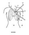
図1を参照すると、低侵襲心臓手術用の構成10が、例示的に示されている。この例では、内視鏡12ならびに2つの器具14および16が、小さいポート15を介して体腔20内に肋骨18を通じて挿入される。この小さいポート15は、約5mmと約100mmの間のサイズを含むことができる。実際の臨床では、ポート15は、職能団体、病院、または手術用機器の製造業者によって発行されたガイドラインを用いて選択される。このガイドラインは、解剖学的ランドマーク、例えば、肋骨、胸骨、乳頭、これらの特徴間の距離、およびこれらの特徴からの距離などに対して入口点を定める。しかし、一般に、この種のガイダンスは、解剖学的構造、患者のサイズ、患者の病気の特殊性などのばらつきを含んでいない。したがって、アクセスに関連した組織損傷および手術時間を最小にすると共に結果を改善するより多くの患者特有のポートの配置が有益であり得る。 Referring to FIG. 1, a minimally invasive
患者特有のポート計画は、治療介入を容易にし、手術時間および合併症率を潜在的に減少させると共に、結果を改善する。実際の標準的な臨床では、手術用アクセス・ポートは、標準的なガイドラインを用いて選択される。患者特有の最適化の欠如によって、準最適なポートに配置された器具が、全ての関心の領域に到達することができない可能性があるという結果になり得る。これは、介入時間を長くさせ、目標箇所に到達するために行われる手術の手数を増大させる。患者特有のアクセス・ポート最適化の手術中の実施は、未解決のままである。 Patient-specific port planning facilitates therapeutic intervention, potentially reduces surgical time and complication rates, and improves results. In actual standard practice, surgical access ports are selected using standard guidelines. The lack of patient-specific optimization can result in an instrument placed in a sub-optimal port may not be able to reach all areas of interest. This increases the intervention time and the number of operations performed to reach the target location. The intraoperative implementation of patient-specific access port optimization remains unresolved.
例えば、器具12、14および16が、体腔20に挿入された後、器具12、14および16は、4自由度(DOF)で、すなわち、挿入および回転に加えてポート15(支点)を中心に枢動する2つの角度を用いて動かすことができる。回転および挿入は、直観的であり使用が容易であるが、角度と内視鏡との間のマッピングは、直観的でなく、習得するのに長い時間がかかり、研究が示すように、低侵襲手術における視覚と手の協調関係に最大の困難性が存在する。 For example, after the
ポートの配置問題を解決することに多くの注目が置かれてきた。手術前の3次元医用画像(例えば、コンピュータ断層撮影(CT)スキャン、磁気共鳴イメージング(MRI)など)に基づいて器具のための最適なポートを計算するコンピュータ・アルゴリズムが開発されてきた。最適計画を手術室内に続いて移行させることは、手術ナビゲーションから知られている標準的なツールトラッキング技術を用いることに焦点が当てられていた。しかし、内視鏡の案内下での器具操作についての非直観的な性質により臨床実施におけるギャップが依然として存在している。手術前のイメージングおよび従来のトラッキング技術(例えば、近赤外光学カメラによる位置特定、コンピュータ・ビジョンによる位置特定、電磁気的位置特定)を用いたポート配置の最適化に基づいた従来技術に提案された方法は、標準的な実際の臨床で用いるのに十分には実用的でない。Much attention has been given to solving the port placement problem. Computer algorithms have been developed that calculate optimal ports for instruments based on pre-operative three-dimensional medical images (eg, computed tomography (CT) scans, magnetic resonance imaging (MRI), etc.). Subsequent transfer of the optimal plan into the operating room has been focused on using standard tool tracking techniques known from surgical navigation. However, gaps in clinical practice still exist due to the non-intuitive nature of instrument operation under endoscopic guidance. Proposed for prior art based on optimization of port placement using pre-operative imaging and traditional tracking techniques (eg, near-infrared optical cameralocation , computer visionlocation , electromagneticlocation ) The method is not practical enough for use in standard actual clinical practice.
手術前の3次元イメージングに基づいて手術の前に行われるポート配置の最適化は、いったん手術が開始すると現状に合っていない古いものになり得る。例えば、心臓手術では、左肺は、しぼまされ、心臓は、心肺ポンプを用いて停止され、器官の異なる配置をもたらす。また、内視鏡は介入者が利用できる唯一のリアルタイムの視覚的フィードバックであるにもかかわらず、ポートは、内視鏡の映像に対してではなく、術前の画像に対して計画される。現実的な患者特有のポート計画は、時間内にかなり大きなオーバーヘッドを必要とし、今までの手術シミュレーション・ツールの臨床応用の限界を示す。また、従来のトラッキング・システムは、通常、手術室内の長いセットアップ時間を招き、注意深い較正を必要とする。トラッキングが後の手術ステージの間に使用されない場合については、準備に必要とされた臨床オーバーヘッドは、許容可能でない可能性がある。ポートの配置位置は、介入器具および内視鏡検査プローブ用の挿入点を定める共に拘束するが、どのようにツールが内視鏡検査画像内の特定の領域に届くように向き合せされるのかに関して直観的なフィードバックがさらに必要とされており、そのフィードバックは、今日の手術では欠如している。したがって、介入処置時の器具の位置特定および操作の改善が必要とされている。The optimization of port placement performed prior to surgery based on pre-surgery three-dimensional imaging can be out of date with the current situation once surgery is initiated. For example, in cardiac surgery, the left lung is deflated and the heart is stopped using a cardiopulmonary pump, resulting in a different arrangement of organs. Also, although the endoscope is the only real-time visual feedback available to the intervention person, the port is planned for pre-operative images, not for endoscopic images. Realistic patient-specific port planning requires significant overhead in time and represents the limitations of clinical application of previous surgical simulation tools. Also, conventional tracking systems usually result in long setup times in the operating room and require careful calibration. For cases where tracking is not used during later surgical stages, the clinical overhead required for preparation may not be acceptable. The location of the port defines and constrains the insertion point for the interventional instrument and endoscopy probe, but with respect to how the tool is oriented to reach a specific area in the endoscopy image. There is a further need for intuitive feedback, which is lacking in today's surgery. Accordingly, there is a need for improved instrumentlocation and operation during interventional procedures.
本原理によれば、位置決め装置は、ポート入口点と位置合わせするための第1の開口部を有する第1の部分を含む。第2の部分が、複数の異なる位置から第1の開口部と位置合わせするように位置決め可能である。作動機構が、第1の部分および第2の部分の少なくとも一方に結合されて、第1の部分と第2の部分の間に形成されたツール軸が第1の開口部を通じて位置合わせされることを可能にするように第1の部分および第2の部分の相対位置を設定し、それによって、ツール軸に設けられたツールが既知の位置および向きを含むようになっている。 In accordance with the present principles, the positioning device includes a first portion having a first opening for alignment with the port entry point. The second portion can be positioned to align with the first opening from a plurality of different positions. An actuating mechanism is coupled to at least one of the first part and the second part, and a tool axis formed between the first part and the second part is aligned through the first opening. The relative positions of the first part and the second part are set so as to enable the tool so that the tool provided on the tool axis includes a known position and orientation.
別の位置決め装置は、ポート入口点と位置合わせするための第1の開口部を有する第1のプレートと、第1の開口部と位置合わせするための第2の開口部を有する第2のプレートとを備える。作動機構は、第1のプレートおよび第2のプレートの少なくとも一方に結合されて、ツール軸が第1の開口部および第2の開口部を通じて位置合わせされることを可能にするように設定され、それによって、ツール軸に設けられたツールが既知の位置および向きでポート入口点を通過するようになっている。 Another positioning device includes a first plate having a first opening for alignment with the port entry point and a second plate having a second opening for alignment with the first opening. With. The actuating mechanism is coupled to at least one of the first plate and the second plate and is set to allow the tool axis to be aligned through the first opening and the second opening; Thereby, the tool provided on the tool shaft passes through the port entry point at a known position and orientation.
さらに別の位置決め装置は、ベースにヒンジで結合された第1のスロット付きアーチと、ベースにヒンジで結合されると共に第1のスロット付きアーチに対して直角に配設された第2のスロット付きアーチとを含む。チャネルは、第1のスロット付きアーチ中のスロット、およびチャネルとポート入口点に対応する回転中心とを位置合わせするための第2のスロット付きアーチのスロットを通過し、それによって、ツール軸の回転が、第1のスロット付きアーチおよび第2のスロット付きアーチの回転によって制御されて、位置合わせにツール軸の既知の位置および向きを与えるようになっている。 Yet another positioning device includes a first slotted arch hinged to the base and a second slot hinged to the base and disposed at right angles to the first slotted arch. Including arches. The channel passes through a slot in the first slotted arch and a slot in the second slotted arch to align the channel with the center of rotation corresponding to the port entry point, thereby rotating the tool axis. Is controlled by rotation of the first slotted arch and the second slotted arch to provide a known position and orientation of the tool axis for alignment.
器具を位置決めする方法は、被検者の第1のポートにスコープを配置するステップと、器具用の第2のポートの位置を決定するステップと、位置決めおよび向き合せ装置を被検者に取り付けるステップであって、この装置は、第2のポートに対してツール軸を位置合わせするために位置が調整可能である少なくとも2つの開口部を含む、取り付けるステップと、スコープの視野に従って少なくとも2つの開口部を通じてツール軸に沿ってツールを位置決めするステップとを含む。 A method of positioning an instrument includes: placing a scope at a first port of a subject; determining a position of a second port for the instrument; and attaching a positioning and orientation device to the subject. The device includes at least two openings that are adjustable in position to align the tool axis with respect to the second port, and at least two openings according to the scope field of view. Positioning the tool along the tool axis.
本開示のこれらおよび他の目的、特徴および利点は、添付図面と併せて読まれる、本開示の例示的な実施形態についての以下の詳細な説明から明らかになろう。 These and other objects, features and advantages of the present disclosure will become apparent from the following detailed description of exemplary embodiments of the present disclosure, read in conjunction with the accompanying drawings.
本開示は、以下の図面を参照して、好ましい実施形態に関する後述の説明を詳細に示すことになる。 The present disclosure will present in detail the following description of preferred embodiments with reference to the following drawings.
本原理によれば、内視鏡デバイス、撮像デバイス、または他の器具に対して手術ツールを位置決めおよび向き合せする構成が提供される。患者特有のポート計画は、内視鏡視野に重ね合わされた手術ツールの位置および経路の視覚化に加えて、内視鏡に対しての介入器具の知識および制御を必要とする。患者特有のポート計画は、外部で患者を登録したトラッキング・デバイスに対しての介入器具の知識および制御を用いて実行することもできる。外部で患者を登録するトラッキング・デバイスには、電磁気的トラッキング方法、光学に基づいたトラッキング方法、カメラによるトラッキング方法、光学的形状センシングなど、または手術中の撮像デバイスが含まれるが、これらに限定されるものではない。 In accordance with the present principles, an arrangement is provided for positioning and orienting a surgical tool relative to an endoscopic device, imaging device, or other instrument. Patient-specific port planning requires knowledge and control of the interventional instrument for the endoscope, in addition to visualization of the position and path of the surgical tool superimposed on the endoscope field of view. Patient specific port planning can also be performed using knowledge and control of interventional instruments for externally registered patient tracking devices. Tracking devices that register patients externally include, but are not limited to, electromagnetic tracking methods, optical based tracking methods, camera tracking methods, optical shape sensing, etc., or intraoperative imaging devices. It is not something.
本発明は、医療器具の観点で説明されるが、本発明の教示は、より広範な範囲に及び、任意の器具に適用可能であることを理解されたい。いくつかの実施形態では、本原理は、複雑な生体または機械システムの追跡または解析に用いられる。特に、本原理は、生体系に対しての内部手術、肺、消化管、排出器、血管などの身体の全領域における手術などに適用可能である。各図に示した要素は、ハードウェアとソフトウェアの様々な組み合わせで実施することができると共に、単一の要素または複数の要素に組み合わせられる機能をもたらす。 Although the present invention is described in terms of a medical device, it should be understood that the teachings of the present invention extend to a broader scope and are applicable to any device. In some embodiments, the present principles are used for tracking or analyzing complex biological or mechanical systems. In particular, the present principle can be applied to internal surgery on a biological system, surgery in the entire region of the body such as the lung, digestive tract, drainage device, and blood vessels. The elements shown in each figure can be implemented in various combinations of hardware and software and provide functionality that can be combined into a single element or multiple elements.
各図に示された様々な要素の機能は、専用ハードウェア、ならびに適切なソフトウェアと関連してソフトウェアを実行できるハードウェアを使用することによって提供することができる。プロセッサによって提供されるとき、これらの機能は、単一の専用プロセッサ、単一の共有プロセッサ、またはいくつかは共有されるような複数の個々のプロセッサによって提供することができる。また、「プロセッサ」または「コントローラ」という用語の明示的使用は、ソフトウェアを実行できるハードウェアを排他的に指すように解釈すべきではない。これらの明示的使用には、デジタル・シグナル・プロセッサ(「DSP」)ハードウェア、ソフトウェアを記憶するためのリード・オンリ・メモリ(「ROM」)、ランダム・アクセス・メモリ(「RAM」)、不揮発性記憶装置などが暗黙的に含まれ得るが、これらに限定されるものではない。 The functionality of the various elements shown in each figure can be provided by using dedicated hardware as well as hardware capable of executing software in conjunction with appropriate software. When provided by a processor, these functions can be provided by a single dedicated processor, a single shared processor, or multiple individual processors, some of which are shared. Also, the explicit use of the terms “processor” or “controller” should not be construed to refer exclusively to hardware capable of executing software. These explicit uses include digital signal processor (“DSP”) hardware, read only memory (“ROM”) for storing software, random access memory (“RAM”), non-volatile A sexual storage device or the like may be implicitly included, but is not limited thereto.
さらに、本発明の原理、態様および実施形態、ならびにその特定の例を挙げる本明細書中の全ての記載は、その構造的な均等物と機能的な均等物とを共に包含することが意図される。加えて、そのような均等物は、現在知られている均等物と将来開発される均等物との両方(すなわち、構造にかかわらず、同じ機能を行うように開発された任意の要素)を含むことが意図される。したがって、例えば、本明細書に表されたブロック図は、本発明の原理を用いる例示的なシステム構成要素および/または電気回路構成の概念図を表すことが当業者によって理解されよう。同様に、任意のフローチャート、フロー図などは、コンピュータ可読記憶媒体に実質的に表すことができ、コンピュータまたはプロセッサが明示的に示されているか否かに拘わらず、そのようなコンピュータまたはプロセッサによって実行される様々なプロセスを表すことが理解されよう。 Furthermore, all statements herein reciting principles, aspects and embodiments of the invention, as well as specific examples thereof, are intended to encompass both structural and functional equivalents thereof. The In addition, such equivalents include both currently known equivalents and equivalents developed in the future (ie, any element developed to perform the same function regardless of structure). Is intended. Thus, for example, it will be appreciated by those skilled in the art that the block diagrams depicted herein represent conceptual diagrams of exemplary system components and / or electrical circuit configurations that employ the principles of the present invention. Similarly, any flowcharts, flow diagrams, etc. may be substantially represented on a computer-readable storage medium and executed by such a computer or processor, whether or not the computer or processor is explicitly shown. It will be understood that it represents the various processes that are performed.
さらに、本発明の実施形態は、コンピュータまたは任意の命令実行システムによってまたはこれらに関連して使用されるプログラム・コードを用意するコンピュータ使用可能記憶媒体またはコンピュータ可読記憶媒体からアクセスできるコンピュータ・プログラム製品の形態をとることができる。この説明のために、コンピュータ使用可能記憶媒体またはコンピュータ可読記憶媒体は、命令実行システム、装置、またはデバイスによってまたはこれらに関連して使用されるプログラムを収容、記憶、通信、伝搬または伝送できる任意の装置であり得る。媒体は、電子、磁気、光学、電磁気、赤外線または半導体のシステム(もしくは装置もしくはデバイス)、または伝播媒体とすることができる。コンピュータ可読媒体の例には、半導体または固体メモリ、磁気テープ、リムーバブル・コンピュータ・ディスケット、ランダム・アクセス・メモリ(RAM)、リード・オンリ・メモリ(ROM)、硬質磁気ディスク、および光ディスクがある。光ディスクの現在の例には、コンパクト・ディスク−読み取り専用メモリ(CD−ROM)、コンパクト・ディスク−リード/ライト(CD−R/W)、Blu−Ray(登録商標)、およびDVDが含まれる。 Furthermore, embodiments of the present invention are directed to a computer program product accessible from a computer-usable or computer-readable storage medium that provides program code for use by or in connection with a computer or any instruction execution system. Can take form. For purposes of this description, a computer-usable or computer-readable storage medium is any that can contain, store, communicate, propagate or transmit a program used by or in connection with an instruction execution system, apparatus, or device. It can be a device. The medium can be an electronic, magnetic, optical, electromagnetic, infrared, or semiconductor system (or apparatus or device) or a propagation medium. Examples of computer readable media include semiconductor or solid state memory, magnetic tape, removable computer diskette, random access memory (RAM), read only memory (ROM), hard magnetic disk, and optical disk. Current examples of optical disks include compact disk-read only memory (CD-ROM), compact disk-read / write (CD-R / W), Blu-Ray (R), and DVD.
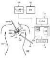
次に、同じ数字が同一または類似の要素を表す図面、初めに図2を参照すると、一実施形態による低侵襲心臓手術用の構成100が例示的に示されている。この例では、内視鏡で案内された手術は、内視鏡画像またはデータ・ストリームに対しての手術ツールの位置の計画、予測、および測定を可能にするようなソフトウェアおよびハードウェアを用いたリアルタイム・ポート位置特定システム120の使用を含む。ポート位置特定システム120は、コンピュータ132から分離して示されているが、コンピュータ132を含むこともでき、またはコンピュータ132で用いることもできる。ポート位置特定システム120は、(1つまたは複数の)ポート位置124、126、したがって内視鏡102または他のツール104などの手術ツールの位置および向きを決める既知の方法を用いることができる。本原理によれば、(概して示された)位置決めおよび向き合せ装置130は、ツール104(または内視鏡102)に較正された態様で取り付けられて、ライブの内視鏡検査データ・ストリームに対しての手術ツール104(または102)のリアルタイム操作、または他の外部トラッキングまたは手術中のイメージング方法を可能にする。このようなデバイスまたは装置130は、内視鏡画像上の外科医によって選択された領域内で手術ツール104を位置特定するように、手術ツール102の位置決めを可能にする。取り付け位置または機構128は、被検者140に示されまたは配置されて、装置130用の位置または装置130を固定する位置を特定する。Referring now to the drawings, in which like numerals represent the same or similar elements, and initially to FIG. 2, a minimally invasive
位置決め装置130は、ポート入口点124と位置合わせするための第1の開口部125を有する第1の部分123を含む。第2の部分127は、第1の開口部125と位置合わせするためのガイドを含む。作動機構142は、第1の部分123および/または第2の部分127の少なくとも一方に結合されると共に、ツール軸が第1の開口部125を通じて位置合わせされることを可能にするように設定され、それによって、ツール軸上に設けられたツール104が、計画121に従って患者特有の位置を通過するようになっている。計画121は、ソフトウェア、および医用画像、測定などによって取得された患者特有のデータを用いて生成および記憶することができる。 The
位置決め装置130を設けることによって、医療器具のより信頼できる位置を、スコープまたはカメラの視野内で実現することができる。このようにして、患者特有の調整が、リアルタイムで一貫しておよび繰り返して行われ、器具配置および介入処置の全体的な成功を改善することができる。ツール位置決めおよび向き合せ構成/装置130の例示実施形態は、以下により詳細に説明される。 By providing the
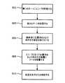
図2の参照に続けて図3を参照すると、一実施形態による臨床ワークフローが例示的に示されている。ブロック202では、ワークフローは、標準的なポート内の内視鏡挿入から開始する。ブロック204では、ポート位置特定システム120を用いて介入器具のための最適なアクセス・ポートを特定および形成する。ブロック206では、本原理による位置決めおよび向き合せ装置130が、最適なアクセス位置において手術器具を取り付けおよび操作する最適なポートの形成の前または後に用いられる。ブロック208では、そこで、外科手術は、身体内での以下のツールの展開を進行または継続し、生理学的なモニタリングからの任意の他の補助情報または手術前の情報に加えて、介入ツールの位置、ツールの向き、(予測されたおよび/または実際の)経路情報のうちの1つまたは複数についてのライブのフィードバックを伴う。このデータは、内視鏡のデータ・ストリーム画像に重ねることができる。Referring to FIG. 3 following reference to FIG. 2, a clinical workflow according to one embodiment is illustratively shown. In
手術中、介入ツールは、様々な向きをとる。したがって、多くの潜在的な向きに対してツールの位置/向きを計画および操作する能力を外科医に与えることが有益となる。外科医は、ポートが選択されると、器具の位置/向きを計画および操作することも可能にされ、視覚と手の協調関係のタスクを簡略化する。 During the surgery, interventional tools take various orientations. Thus, it would be beneficial to give the surgeon the ability to plan and manipulate the position / orientation of the tool for many potential orientations. The surgeon can also plan and manipulate the position / orientation of the instrument once the port is selected, simplifying the task of visual and hand coordination.
再び図2を参照すると、以下の本実施形態における装置130の操作は、手動、半自動、または自動で行うことができる。プロセッサ134、メモリ136、ディスプレイ137、およびユーザ・インターフェース138を有するコンピュータ・システム132を用いて、装置130の動きを制御し、ポート位置または解剖学的ランドマークに対しての装置130の位置特定または配置を支援し、計画を発展させるために用いられ、またはさもなければ使用者に対して案内を行うことができる。これらの実施形態は、最適なポート位置特定配置と組み合わされて、低侵襲の内視鏡の案内による処置を容易にする。Referring to FIG. 2 again, the following operation of the
装置130は、センサ144とアクチュエータ・デバイス/機構142との間のフィードバック制御ループに基づいた(半)自動電気機械、電気−光−機械作動デバイス142を備えることができる。本説明は、全ての可能な構成の網羅的なリストであることは意図されず、むしろ本原理による有用な特徴を一例を通じて示す。代替の実施形態、配置、構成なども用いることができると共に企図される。 The
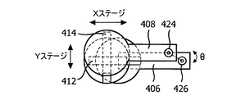
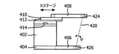
図4A〜図4Dを参照すると、一実施形態による内視鏡ポートまたは他の手術用デバイスのための位置決めおよび向き合せ装置400が示されている。図4Aは、装置400の斜視図を示す。図4Bは、装置400の上面図を示す。図4Cは、装置400の側面図を示す。図4Dは、装置400の背面図を示す。この装置400は、2つのリニア・ステージ、つまり円筒形支持体402に接続されたXステージ412およびYステージ414を備える。円筒形支持体402の下部において、そのような目的にために、ベース404を、被検者の身体または取り付け機構(図示せず)に接続する。ベース404およびプラットフォーム410は、それぞれプレートまたは梁406および408を備え、それぞれベース404およびプラットフォーム410から延びている。梁408は、ポート入口箇所の開口部426を中心にして回転の固定点を維持し、内視鏡視野に対して知られた空間構成を与える。梁408は、第2の点424を保持する。第2の点424は、シリンダ402のベース404にある梁406の開口部426の回転の固定点と共に、軸420を定める。これを通じて、ツールまたは針を特定の向きでポート内に挿入することができる。2つの点424および426は、硬質の中空チャネル(例えば、ガイドなど)を保持するように構成され、そのチャネルを通じてツール(図示せず)を挿入することができる。2つの点424および426の各々は、正しいツールの位置決めを可能にする球面軸受を備えることができる。 4A-4D, a positioning and
2つのリニア・ステージ(Xステージ412およびYステージ414)の位置を変更することによって、回転点に対してのツールのヨー角およびピッチ角(θおよびφ)を修正することができる。Xステージ412およびYステージ414は、手動レバー付きの親ねじ、エンコーダ・ホイール、または運動スケールを用いて手動で制御することができ、あるいはステージ412、414は、親ねじを備えたステッパまたはサーボ・モータ・システムならびにエンコーダまたはポテンショメータを用いて制御することができる(上記の図2も参照)。 By changing the position of the two linear stages (
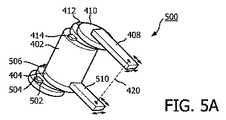
図5A〜図5Dを参照すると、別の実施形態による内視鏡ポートまたは他の手術用デバイスのための位置決めおよび向き合せ装置500が示されている。図5Aは装置500の斜視図を示す。図5Bは装置500の上面図を示す。図5Cは装置500の側面図を示す。図5Dは装置500の背面図を示す。装置500は、4つのリニア・ステージ、つまり円筒形支持体402の上部に接続されたXステージ412およびYステージ414、ならびに円筒形支持体402のベース404に接続されたXステージ506およびYステージ504を備える。円筒形支持体402の下部において、そのような目的にために、ベース502を、被検者の身体または取り付け機構(図示せず)に接続する。 With reference to FIGS. 5A-5D, a positioning and
円筒形支持体402の底部において、梁510は、ポート入口箇所の位置において回転の固定点426を維持する。2つの下側リニア・ステージ、「Xステージ1」506および「Yステージ1」504は、ポート・アクセス箇所に対して知られた位置に設けられている。円筒形支持体402の上部にあるリニア・ステージ、「Xステージ2」412および「Yステージ2」414は、回転点に対してツールのヨー角およびピッチ角(θおよびφ)を変更するように構成される。XYステージは、(フィードバック用の)エンコーダ・ホイールまたは運動スケールと組み合わされた手動レバー付きの親ねじを用いて手動で制御することができ、あるいは親ねじを備えたステッパまたはサーボ・モータ・システム、ならびにエンコーダまたはポテンショメータを用いて制御することができる。上述のように、これらは、(半)自動フィードバック制御ループを形成する。本実施形態における2セットのリニア・ステージを備えることの利点の1つは、底部リニア・ステージ506、504によって定められた「回転点」(X1,Y1)を動かす能力を与えることを含むことである。これは、ツールとポート位置を位置合わせするときに役立つことができる。 At the bottom of the
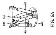
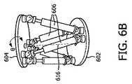
図6A〜図6Cを参照すると、別の実施形態は、スチュワート・プラットフォーム組立体600を含むことができ、スチュワート・プラットフォーム組立体600は、3自由度(DOF)のプラットフォームの運動学を与える。組立体600は、ベースプラットフォーム602を備えており、ベースプラットフォーム602を、被検者への取り付けのために被検者の身体または取り付け機構(図示せず)に接続する。上側プラットフォーム604は、複数のアクチュエータ606、好ましくはリニア・アクチュエータによってベースプラットフォーム602に結合される。アクチュエータ606は、ペアでグループ化できると共に、「V」形状構成を有することができる。アクチュエータ606は、手動で作動させることができ、またはアクチュエータ606は、油圧シリンダまたは空気圧シリンダ、電気機械機構などを備えることができる。アクチュエータ606は、プラットフォーム602とプラットフォーム604の間および各アクチュエータ606の間に位置するツールチャネルの回転を可能にするように制御することができる。ベースプラットフォーム604の一部は、回転中心に貫通穴610を含むことができ、貫通穴610は、ポート入口点と位置合わせすることができる。上側プラットフォーム604の同様の一部は、ツールチャネルの通過を可能にするために貫通穴612を含むことができる。穴610および612は、穴610および612の種々の構成において位置合わせを可能にするために球面継手を有することができる。 Referring to FIGS. 6A-6C, another embodiment may include a Stewart platform assembly 600 that provides a three-degree-of-freedom (DOF) platform kinematics. The assembly 600 includes a
プラットフォーム602とプラットフォーム604の間でアクチュエータ606のペアを動かすことによって、回転中心に対してのツール経路616のヨー角およびピッチ角(θおよびφ)(それぞれ図6Bおよび図6C)は修正される。アクチュエータ606は、位置センサ(図示せず)を用いたステッパまたはサーボ・モータを用いて動かすことができる。アクチュエータ606は、各軸で動かされる距離を評価するためにいくらかの距離固有受容(proprioception)がある限り、手動または電気−光−機械制御下で動かすことができる単純な親ねじを備えることができる。 By moving a pair of
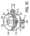
図7A〜図7Dを参照すると、別の実施形態による内視鏡ポートまたは他の手術用デバイスのための位置決めおよび向き合せ装置700が示されている。図7Aは装置700の斜視図を示す。図7Bは装置700の第1の側面図を示す。図7Cは装置700の上面図を示す。図7Dは装置700の第2の側面図を示す。装置700は、2つのスロット付きアーチ704および706を備えており、それぞれは、中央に配設されたスロット714および716を含む。アーチ704および706は、ベース702にヒンジで接続され、ベース702は、アクセル708および710のヒンジ継手のためのハウジングとして働く。アクセル708および710は、ヒンジ式接続を形成し、それらのそれぞれのアーチ704および706と接続または一体形成されて、アクセル708および710を中心にしたアーチ704および706の回転を可能にする。ベース702は、内視鏡または他の器具のためのワーキング・チャネルを位置決めまたは向き決めするように装置を用いて処置を行うために被検者の身体または取り付け機構(図示せず)に接続する。 Referring to FIGS. 7A-7D, a positioning and
アーチ704、706は、ポート入口点に可能な限り近くに位置する回転中心722に対して2つの角度の自由度(ヨーおよびピッチ、すなわちθおよびφ)でツール軸720を位置決めすることができる2軸系を与える。回転中心722は、チューブまたはチャネル(例えば、ガイド)712と位置合わせされ、ツール軸720は、チャネル712を通過し、回転中心を通過して、回転中心722にまたはその周りに位置決めされているポートを通じて被検者に入る。装置700は、ポート入口箇所および撮像データ・ストリームに対して既知の幾何形状で内視鏡検査案内システムに取り付けることができる。
装置700は、多数の可能な変形形態を含むことができる。その例は、非網羅的なリストで以下に記載される。装置700は、ツール(ツール軸720)を所望の角度で位置決めするために、2つのアーチ704および706の各々について手動の動きを与えることができる。装置700は、ツール(ツール軸720)を位置決めするために2つのアーチ704および706の手動の動きを与えることができ、ブレーキ740(図7Cだけに示された)は、必要に応じてアーチ704および706を固定化する(例えば、回転を防ぐ)ために点「A」で位置決めすることができる。装置700は、点「B」にセンサなしで(図7Cだけに示された)エンコーダ・ホイール742を備えることができ、アーチ704、706とエンコーダ・ホイール742に印が付けらえたスケールとを位置合わせすることを可能にする。これによって、各アーチの位置の直接の視覚的フィードバックを可能にする。装置700は、点「B」におけるアクセル708および710に対応する2つの軸ごとに光学エンコーダまたはポテンショメータを備えることができる。これは、2つのアーチ704および706の各々の位置についての位置フィードバックを電気(または光)信号として与えることができる。現在の位置は、参照のために同様に画面またはモニタ(ディスプレイ137)に表示することができる。 The
装置700は、光学エンコーダ(またはポテンショメータ)システム742と発光ダイオード(LED)ディスプレイとの組み合わせを点「B」において含むことができ、そこではLEDディスプレイは、線または同様の標識を用いて各アーチ704、706の所望の位置を示す。このようにして、使用者は、アーチ704、706の位置を手動または自動で設定することができ、光学エンコーダ(またはポテンショメータ)は、ディスプレイ137上にアーチ704、706の各々の現在の位置を示すことになる。使用者は、アーチとLEDに表示された線とを位置合わせすることができる。
装置700は、点「A」ごとにステッパ・モータ(図示せず)を備えることができる。これは、ツールの位置決めの電動式制御を可能にする。点「A」におけるステッパ・モータは、点「B」に位置するまたはステッパ・モータ・ユニットに含まれる光学エンコーダ(またはポテンショメータ)で増大することができ、電動式制御と同様に位置フィードバックを与える。装置700は、点「A」ごとにサーボ・モータ・システムを備えることができる。このサーボ・モータ・システムは、モータおよび光学エンコーダ(またはポテンショメータ)を備えることができ、それによってツールの位置決めの電動式制御を可能にする。
本実施形態は、角度の自由度を制御することに着目したが、ツールまたはツールチャネルの前進および回転も企図される。前進および回転は、手動、半自動、または自動で行うこともできる。自動的な前進および回転は、モータ、ブレーキなどの使用を含むことができる。 Although this embodiment focused on controlling the degree of angular freedom, advancement and rotation of the tool or tool channel is also contemplated. Advancement and rotation can be performed manually, semi-automatically, or automatically. Automatic advance and rotation can include the use of motors, brakes, and the like.
本実施形態は、多くの異なる用途に用いることができ、特に、内視鏡案内式の低侵襲手術に役立つ。例えば、心臓手術、低侵襲冠動脈バイパス術、心房中隔欠損閉鎖、バルブの修理/交換、腹腔鏡手術、子宮摘出術、前立腺切除術、胆嚢の手術、自然開口部越経管腔的手術(NOTES)、肺/気管支鏡手術、神経外科的介入などである。 This embodiment can be used for many different applications, and is particularly useful for endoscope-guided minimally invasive surgery. For example, cardiac surgery, minimally invasive coronary artery bypass surgery, atrial septal defect closure, valve repair / replacement, laparoscopic surgery, hysterectomy, prostatectomy, gallbladder surgery, natural opening transluminal surgery (NOTES) ), Pulmonary / bronchoscopic surgery, neurosurgical interventions and the like.
図8を参照すると、器具を位置決めする別の方法が、例示的に示されている。ブロック802では、スコープ(例えば、内視鏡)は、被検者内の第1のポートに配置される。スコープ・ポートは、標準的な配置、患者特有の配置、ポート最適化配置などを含むポート位置特定技法を用いて配置することができる。ブロック804では、器具用の第2のポートの位置が決定される。好ましくは、これは、ポート位置特定システムを用いて、位置決めおよび向き合せ装置について被検者への取り付け位置を決定することを含む。そのようなシステムは、患者特有のデータを使用して位置決めおよび向き合せ装置の配置について最適位置を選択する。Referring to FIG. 8, another method of positioning the instrument is exemplarily shown. At
ブロック806では、位置決めおよび向き合せ装置が、被検者に取り付けられる。位置決めおよび向き合せ装置は、第2のポートに対してツール軸を位置合わせするために位置が調整可能である2つの穴を含む。位置決めおよび向き合せ装置は、ポート入口点と位置合わせするための第1の開口部を有する第1のプレートと、第1の開口部と位置合わせするための第2の開口部を有する第2のプレートと、第1のプレートと第2のプレートにまたはこれらプレートの間に結合されて、ツール軸が第1の開口部および第2の開口部を通じて位置合わせされることを可能にするように設定される作動機構とを備えており、それによって、ツール軸に設けられたツールが計画に従った患者特有の位置へ通過するようになっている。位置決めおよび向き合せ装置は、ベースにヒンジで結合された第1のスロット付きアーチと、ベースにヒンジで結合されると共に第1のスロット付きアーチに対して直角に配設された第2のスロット付きアーチと、チャネルであって、第1のスロット付きアーチ中のスロット、およびチャネルとポート入口点に対応する回転中心とを位置合わせするための第2のスロット付きアーチのスロットを通じて配置され貫通するチャネルとを備えており、それによって、ツール軸の回転が、計画に従った患者特有の位置との位置合わせを制御するために第1のスロット付きアーチおよび第2のスロット付きアーチの回転によって制御されるようになっている。他の構成も、位置決めおよび向き合せ装置に用いることができ、例えば、2つ以上のプレートまたは位置決め点が用いられてもよい。これは、内視鏡、手術用デバイス、針などが挙げられる器具の位置決めおよび向き合せを支援するための調整機構があるか否かに拘わらず、本明細書に記載の要素または特別に設計されたツールの組み合わせを含むことができる。 At
ブロック808では、(1つまたは複数の)ツールが、スコープの視野に従って2つの穴を通じてツール軸に沿って位置決めされる。複数のポートおよび複数の位置決めおよび向き合せ装置が企図される。好ましくは、ツールは、使用者の機能を簡略化するために、カメラまたは撮像デバイスの視野内にまたは予測可能なもしくは知られた位置内に維持される。ツールの位置決めおよび向き合せは、スコープの位置および/または向きからのフィードバックを用いて制御することができる。例えば、第1のポート中のスコープは、器具と平行な面内にあってもよいが、器具およびスコープが互いに向かい合うように斜めにされてもよい。代替として、スコープおよび器具は、共に組織の同じ領域に向かって平行であってもよい。他の構成も企図される。ブロック810では、位置決めおよび向き合せ装置の設置位置において器具を用いて処置が継続または実行される。この設定位置は、処置前、処置中または処置後に必要に応じて(手動または自動で)調整または移動することができる。 At
添付の特許請求の範囲の解釈においては、以下のことを理解されたい。
a)「備える、有する、含む(comprising)」という語は、所与の請求項に挙げられたもの以外の他の要素または行為の存在を除外するものではない。
b)要素に先行する「1つの(a, an)」という単語は、複数のそのような要素の存在を除外するものではない。
c)特許請求の範囲中の任意の参照符号は、その範囲を限定するものではない。
d)いくつかの「手段(means)」は、同じ項目(item)、またはハードウェア、またはソフトウェアにより実行される構造または機能によって表すことができる。
e)特段示されない限り、行為の特定の順序が必要とされることは意図されていない。In interpreting the appended claims, it should be understood that:
a) The word “comprising” does not exclude the presence of other elements or acts than those listed in a given claim.
b) The word “a, an” preceding an element does not exclude the presence of a plurality of such elements.
c) any reference signs in the claims do not limit their scope;
d) Several “means” can be represented by the same item, or a structure or function performed by hardware or software.
e) Unless otherwise indicated, it is not intended that a specific order of actions be required.
(例示的であり、限定するものでないことが意図されている)患者特有のポートの配置中に手術ツールの位置決めおよび向き合せの好ましい実施形態を説明してきたが、上記の教示に鑑みて当業者により修正および変更がなされてもよいことに留意されたい。したがって、開示した本開示の特定の実施形態において変更がなされることがあり、この変更は、添付の特許請求の範囲によって概略が述べられるような本明細書に開示した実施形態の範囲内にあることを理解されたい。したがって、特許法によって要求される詳細および特徴を説明してきたが、権利主張され、特許権によって保護されることが望まれるものは、添付の特許請求の範囲に記載されている。 While preferred embodiments of surgical tool positioning and orientation have been described during placement of patient-specific ports (which are intended to be exemplary and not limiting), those skilled in the art in view of the above teachings It should be noted that modifications and changes may be made. Accordingly, changes may be made in the particular embodiments of the disclosure disclosed which are within the scope of the embodiments disclosed herein as outlined by the appended claims. Please understand that. Thus, while the details and features required by the patent law have been described, what is claimed and desired protected by patent rights is set forth in the appended claims.
Claims (9)
Translated fromJapaneseポート入口点と位置合わせするための第1の開口部を有する第1の部分と、
複数の異なる位置から第1の開口部と位置合わせするために配置可能である第2の部分と、
第1の部分および第2の部分の少なくとも一方に結合されて、第1の部分と第2の部分との間に形成されたツール軸が第1の開口部を通じて位置合わせされることを可能にするように第1の部分および第2の部分の相対位置を設定し、それによって、前記ツール軸に設けられたツールが既知の位置および向きを含むようになっている作動機構と、を含み、
前記作動機構は、第1の開口部に対して第2の部分を調整する2つの直交ステージを備える、
位置決め装置。A positioning device, wherein the positioning device:
A first portion having a first opening for alignment with a port entry point;
A second portion that can be arranged to align with the first opening from a plurality of different positions;
Coupled to at least one of the first portion and the second portion to allow a tool axis formed between the first portion and the second portion to be aligned through the first opening. An actuating mechanism configured to set a relative position of the first part and the second part so that a tool provided on the tool axis includes a known position and orientation;
The actuating mechanism comprises two orthogonal stages that adjust the second portion relative to the first opening,
Positioning device.
ポート入口点と位置合わせするための第1の開口部を有する第1のプレートと、
第1の開口部と位置合わせするための第2の開口部を有する第2のプレートと、
第1のプレートおよび第2のプレートの少なくとも一方に結合されて、ツール軸が第1の開口部および第2の開口部を通じて位置合わせされることを可能にするように設定され、それによって、前記ツール軸に設けられたツールが既知の位置および向きで前記ポート入口点を通過するようになっている作動機構と、を含み、
前記作動機構は、第1の開口部に対して第2のプレートを調整する2つの直交ステージを備える、
位置決め装置。A positioning device, wherein the positioning device:
A first plate having a first opening for alignment with a port entry point;
A second plate having a second opening for alignment with the first opening;
Coupled to at least one of the first plate and the second plate and configured to allow the tool axis to be aligned through the first opening and the second opening, thereby An actuation mechanism adapted to pass through the port entry point in a known position and orientation with a tool provided on the tool shaft;
The actuation mechanism comprises two orthogonal stages that adjust the second plate relative to the first opening,
Positioning device.
Applications Claiming Priority (3)
| Application Number | Priority Date | Filing Date | Title |
|---|---|---|---|
| US201161566762P | 2011-12-05 | 2011-12-05 | |
| US61/566,762 | 2011-12-05 | ||
| PCT/IB2012/056687WO2013084107A2 (en) | 2011-12-05 | 2012-11-23 | Positioning and orientation of surgical tools during patient specific port placement |
Publications (2)
| Publication Number | Publication Date |
|---|---|
| JP2015502814A JP2015502814A (en) | 2015-01-29 |
| JP6220345B2true JP6220345B2 (en) | 2017-10-25 |
Family
ID=47520200
Family Applications (1)
| Application Number | Title | Priority Date | Filing Date |
|---|---|---|---|
| JP2014545400AExpired - Fee RelatedJP6220345B2 (en) | 2011-12-05 | 2012-11-23 | Surgical tool positioning and orientation during patient-specific port placement |
Country Status (7)
| Country | Link |
|---|---|
| US (1) | US10687911B2 (en) |
| EP (1) | EP2787918B1 (en) |
| JP (1) | JP6220345B2 (en) |
| CN (1) | CN103974672B (en) |
| BR (1) | BR112014013387A2 (en) |
| RU (1) | RU2662872C2 (en) |
| WO (1) | WO2013084107A2 (en) |
Families Citing this family (17)
| Publication number | Priority date | Publication date | Assignee | Title |
|---|---|---|---|---|
| US9222996B2 (en) | 2013-03-15 | 2015-12-29 | The Brigham And Women's Hospital, Inc. | Needle placement manipulator with two rotary guides |
| US10274553B2 (en) | 2013-03-15 | 2019-04-30 | Canon U.S.A., Inc. | Needle placement manipulator with attachment for RF-coil |
| JP6467434B2 (en) | 2014-02-27 | 2019-02-13 | ザ ブリガム アンド ウィメンズ ホスピタル インコーポレイテッドThe Brigham and Women’s Hospital, Inc. | Mounting device |
| US10251670B2 (en)* | 2014-05-09 | 2019-04-09 | Canon U.S.A., Inc. | Positioning apparatus |
| JP7045664B2 (en) | 2014-09-12 | 2022-04-01 | ザ ブリガム アンド ウィメンズ ホスピタル インコーポレイテッド | Needle positioning device |
| JP6634446B2 (en) | 2014-10-23 | 2020-01-22 | コヴィディエン リミテッド パートナーシップ | Method and apparatus for controlling a surgical instrument using a surgical port assembly |
| CN106821497B (en)* | 2017-03-16 | 2023-10-31 | 上海市肺科医院 | Precise positioning and disposal method of target site and auxiliary device |
| US9867673B2 (en) | 2015-07-14 | 2018-01-16 | Canon U.S.A, Inc. | Medical support device |
| US10639065B2 (en) | 2015-07-21 | 2020-05-05 | Canon U.S.A., Inc. | Medical assist device |
| WO2017132505A1 (en)* | 2016-01-29 | 2017-08-03 | Canon U.S.A., Inc. | Tool placement manipulator |
| JP6831642B2 (en) | 2016-04-15 | 2021-02-17 | 川崎重工業株式会社 | Surgical system |
| JP6948389B2 (en) | 2016-10-19 | 2021-10-13 | キヤノン ユーエスエイ, インコーポレイテッドCanon U.S.A., Inc | Placement manipulators and attachments for positioning puncture devices |
| US10548674B2 (en)* | 2017-07-06 | 2020-02-04 | YellowDot Innovations, LLC | Robotic guide for medical device |
| RU199805U1 (en)* | 2020-03-13 | 2020-09-21 | Федеральное государственное бюджетное учреждение науки Институт мозга человека им. Н.П. Бехтеревой Российской академии наук | Device for simulating stereotaxic neurosurgical interventions |
| WO2021255908A1 (en)* | 2020-06-18 | 2021-12-23 | 国立大学法人東京医科歯科大学 | Surgical instrument holding mechanism |
| RU2766975C1 (en)* | 2020-09-22 | 2022-03-16 | Общество с ограниченной ответственностью "Интервенционные радиологические системы" (ООО "ИРС") | Method for positioning a medical instrument for invasive surgery and x-ray contrast grid and stereotactic holder for its implementation |
| US12268360B2 (en)* | 2022-05-16 | 2025-04-08 | Medtronic Navigation, Inc. | Manual hexapod locking mechanism |
Family Cites Families (21)
| Publication number | Priority date | Publication date | Assignee | Title |
|---|---|---|---|---|
| US5980455A (en) | 1993-02-22 | 1999-11-09 | Heartport, Inc. | Method for manipulating a tissue structure within a thoracic cavity |
| US5638819A (en) | 1995-08-29 | 1997-06-17 | Manwaring; Kim H. | Method and apparatus for guiding an instrument to a target |
| RU15269U1 (en)* | 2000-04-27 | 2000-10-10 | Бондарев Александр Анатольевич | DEVICE FOR FIXING TROACARS, ENDOSCOPIC INSTRUMENTS AND OPTICAL INSTRUMENTS |
| JP4629843B2 (en)* | 2000-09-29 | 2011-02-09 | 古河電気工業株式会社 | Semiconductor laser module and manufacturing method and system thereof |
| US6533794B2 (en) | 2001-04-19 | 2003-03-18 | The Ohio State University | Simplified stereotactic apparatus and methods |
| US7636596B2 (en) | 2002-12-20 | 2009-12-22 | Medtronic, Inc. | Organ access device and method |
| ES2288335B1 (en)* | 2004-11-04 | 2008-11-16 | Instituto Cientifico Y Tecnologico De Navarra, S.A. | SUPPORT TO STRENGTHEN A SURGICAL TOOL. |
| WO2006081409A2 (en) | 2005-01-28 | 2006-08-03 | Massachusetts General Hospital | Guidance and insertion system |
| US7967742B2 (en) | 2005-02-14 | 2011-06-28 | Karl Storz Imaging, Inc. | Method for using variable direction of view endoscopy in conjunction with image guided surgical systems |
| US7927271B2 (en) | 2006-05-17 | 2011-04-19 | C.R. Bard, Inc. | Endoscope tool coupling |
| EP1958588A3 (en)* | 2007-02-19 | 2010-09-22 | Radi Medical Devices AB | Medical guide for guiding a medical instrument |
| US9289270B2 (en)* | 2007-04-24 | 2016-03-22 | Medtronic, Inc. | Method and apparatus for performing a navigated procedure |
| US8175677B2 (en) | 2007-06-07 | 2012-05-08 | MRI Interventions, Inc. | MRI-guided medical interventional systems and methods |
| CN101801301B (en)* | 2007-06-07 | 2013-09-25 | 核磁共振成像介入技术有限公司 | Mri-guided medical interventional systems and methods |
| JP4472728B2 (en)* | 2007-06-14 | 2010-06-02 | オリンパスメディカルシステムズ株式会社 | Endoscope system |
| US8315689B2 (en)* | 2007-09-24 | 2012-11-20 | MRI Interventions, Inc. | MRI surgical systems for real-time visualizations using MRI image data and predefined data of surgical tools |
| US7827325B2 (en) | 2007-10-31 | 2010-11-02 | International Business Machines Corporation | Device, system, and method of speculative packet transmission |
| DE102009012987A1 (en)* | 2008-07-22 | 2010-02-11 | Saia-Burgess Dresden Gmbh | Positioning device for laboratory and medical devices, has carrier with positioning field, where actuator is coupled with laboratory and medical device |
| US8747418B2 (en)* | 2008-08-15 | 2014-06-10 | Monteris Medical Corporation | Trajectory guide |
| WO2011088400A2 (en)* | 2010-01-14 | 2011-07-21 | The Regents Of The University Of California | Apparatus, system, and method for robotic microsurgery |
| US8535335B2 (en)* | 2010-04-13 | 2013-09-17 | Iucf-Hyu (Industry-University Cooperation Foundation Hanyang University) | Needle-coupled parallel mechanism |
- 2012
- 2012-11-23JPJP2014545400Apatent/JP6220345B2/ennot_activeExpired - Fee Related
- 2012-11-23WOPCT/IB2012/056687patent/WO2013084107A2/enactiveApplication Filing
- 2012-11-23RURU2014127517Apatent/RU2662872C2/ennot_activeIP Right Cessation
- 2012-11-23EPEP12812384.1Apatent/EP2787918B1/ennot_activeNot-in-force
- 2012-11-23CNCN201280059949.8Apatent/CN103974672B/ennot_activeExpired - Fee Related
- 2012-11-23USUS14/362,225patent/US10687911B2/ennot_activeExpired - Fee Related
- 2012-11-23BRBR112014013387Apatent/BR112014013387A2/ennot_activeApplication Discontinuation
Also Published As
| Publication number | Publication date |
|---|---|
| BR112014013387A2 (en) | 2020-01-07 |
| WO2013084107A3 (en) | 2013-08-08 |
| US20140350572A1 (en) | 2014-11-27 |
| WO2013084107A2 (en) | 2013-06-13 |
| RU2014127517A (en) | 2016-02-10 |
| RU2662872C2 (en) | 2018-07-31 |
| EP2787918A2 (en) | 2014-10-15 |
| JP2015502814A (en) | 2015-01-29 |
| CN103974672A (en) | 2014-08-06 |
| CN103974672B (en) | 2017-03-22 |
| EP2787918B1 (en) | 2018-05-23 |
| US10687911B2 (en) | 2020-06-23 |
Similar Documents
| Publication | Publication Date | Title |
|---|---|---|
| JP6220345B2 (en) | Surgical tool positioning and orientation during patient-specific port placement | |
| RU2668490C2 (en) | Guidance tools to manually steer endoscope using pre-operative and intra-operative 3d images | |
| EP3003180B1 (en) | Localization of robotic remote center of motion point using custom trocar | |
| US10646290B2 (en) | System and method for configuring positions in a surgical positioning system | |
| JP2022502179A (en) | Systems and methods for endoscopically assisted percutaneous medical procedures | |
| JP6404713B2 (en) | System and method for guided injection in endoscopic surgery | |
| JP7041068B2 (en) | Control units, systems, and methods for controlling hybrid robots with proximal and flexible distal parts. | |
| CN119950032A (en) | Surgical assistance system and representation method | |
| CA2917654C (en) | System and method for configuring positions in a surgical positioning system | |
| JP2021502186A (en) | Systems and methods for guiding ultrasonic probes | |
| JP2018521774A (en) | Endoscopic guidance from interactive planar slices of volume images | |
| US20140343407A1 (en) | Methods for the assisted manipulation of an instrument, and associated assistive assembly | |
| US20250235287A1 (en) | Computer-assisted distance measurement in a surgical space | |
| JP7383608B2 (en) | Multi-stage robot for anatomical structure intervention | |
| US20250064522A1 (en) | Pre-operative planning for a multi-arm robotic surgical system | |
| WO2025212319A1 (en) | Computer-assisted annotation of subsurface structures onto a surface | |
| WO2025064440A1 (en) | Computer assisted registration and tracking of models of anatomical objects | |
| WO2015118466A1 (en) | Robot angular setup using current from joints |
Legal Events
| Date | Code | Title | Description |
|---|---|---|---|
| A621 | Written request for application examination | Free format text:JAPANESE INTERMEDIATE CODE: A621 Effective date:20151120 | |
| A977 | Report on retrieval | Free format text:JAPANESE INTERMEDIATE CODE: A971007 Effective date:20160923 | |
| A131 | Notification of reasons for refusal | Free format text:JAPANESE INTERMEDIATE CODE: A131 Effective date:20161018 | |
| A521 | Request for written amendment filed | Free format text:JAPANESE INTERMEDIATE CODE: A523 Effective date:20170117 | |
| A02 | Decision of refusal | Free format text:JAPANESE INTERMEDIATE CODE: A02 Effective date:20170418 | |
| A521 | Request for written amendment filed | Free format text:JAPANESE INTERMEDIATE CODE: A523 Effective date:20170809 | |
| A911 | Transfer to examiner for re-examination before appeal (zenchi) | Free format text:JAPANESE INTERMEDIATE CODE: A911 Effective date:20170818 | |
| TRDD | Decision of grant or rejection written | ||
| A01 | Written decision to grant a patent or to grant a registration (utility model) | Free format text:JAPANESE INTERMEDIATE CODE: A01 Effective date:20170905 | |
| A61 | First payment of annual fees (during grant procedure) | Free format text:JAPANESE INTERMEDIATE CODE: A61 Effective date:20170929 | |
| R150 | Certificate of patent or registration of utility model | Ref document number:6220345 Country of ref document:JP Free format text:JAPANESE INTERMEDIATE CODE: R150 | |
| LAPS | Cancellation because of no payment of annual fees |