JP6218806B2 - Lighting device - Google Patents
Lighting deviceDownload PDFInfo
- Publication number
- JP6218806B2 JP6218806B2JP2015506335AJP2015506335AJP6218806B2JP 6218806 B2JP6218806 B2JP 6218806B2JP 2015506335 AJP2015506335 AJP 2015506335AJP 2015506335 AJP2015506335 AJP 2015506335AJP 6218806 B2JP6218806 B2JP 6218806B2
- Authority
- JP
- Japan
- Prior art keywords
- group
- illumination
- light sources
- sealing
- maximum value
- Prior art date
- Legal status (The legal status is an assumption and is not a legal conclusion. Google has not performed a legal analysis and makes no representation as to the accuracy of the status listed.)
- Active
Links
Images


Classifications
- B—PERFORMING OPERATIONS; TRANSPORTING
- B32—LAYERED PRODUCTS
- B32B—LAYERED PRODUCTS, i.e. PRODUCTS BUILT-UP OF STRATA OF FLAT OR NON-FLAT, e.g. CELLULAR OR HONEYCOMB, FORM
- B32B38/00—Ancillary operations in connection with laminating processes
- B32B38/0008—Electrical discharge treatment, e.g. corona, plasma treatment; wave energy or particle radiation
- B—PERFORMING OPERATIONS; TRANSPORTING
- B23—MACHINE TOOLS; METAL-WORKING NOT OTHERWISE PROVIDED FOR
- B23K—SOLDERING OR UNSOLDERING; WELDING; CLADDING OR PLATING BY SOLDERING OR WELDING; CUTTING BY APPLYING HEAT LOCALLY, e.g. FLAME CUTTING; WORKING BY LASER BEAM
- B23K26/00—Working by laser beam, e.g. welding, cutting or boring
- B23K26/0006—Working by laser beam, e.g. welding, cutting or boring taking account of the properties of the material involved
- B—PERFORMING OPERATIONS; TRANSPORTING
- B23—MACHINE TOOLS; METAL-WORKING NOT OTHERWISE PROVIDED FOR
- B23K—SOLDERING OR UNSOLDERING; WELDING; CLADDING OR PLATING BY SOLDERING OR WELDING; CUTTING BY APPLYING HEAT LOCALLY, e.g. FLAME CUTTING; WORKING BY LASER BEAM
- B23K26/00—Working by laser beam, e.g. welding, cutting or boring
- B23K26/02—Positioning or observing the workpiece, e.g. with respect to the point of impact; Aligning, aiming or focusing the laser beam
- B23K26/06—Shaping the laser beam, e.g. by masks or multi-focusing
- B23K26/064—Shaping the laser beam, e.g. by masks or multi-focusing by means of optical elements, e.g. lenses, mirrors or prisms
- B23K26/0648—Shaping the laser beam, e.g. by masks or multi-focusing by means of optical elements, e.g. lenses, mirrors or prisms comprising lenses
- B—PERFORMING OPERATIONS; TRANSPORTING
- B23—MACHINE TOOLS; METAL-WORKING NOT OTHERWISE PROVIDED FOR
- B23K—SOLDERING OR UNSOLDERING; WELDING; CLADDING OR PLATING BY SOLDERING OR WELDING; CUTTING BY APPLYING HEAT LOCALLY, e.g. FLAME CUTTING; WORKING BY LASER BEAM
- B23K26/00—Working by laser beam, e.g. welding, cutting or boring
- B23K26/352—Working by laser beam, e.g. welding, cutting or boring for surface treatment
- B23K26/354—Working by laser beam, e.g. welding, cutting or boring for surface treatment by melting
- B—PERFORMING OPERATIONS; TRANSPORTING
- B23—MACHINE TOOLS; METAL-WORKING NOT OTHERWISE PROVIDED FOR
- B23K—SOLDERING OR UNSOLDERING; WELDING; CLADDING OR PLATING BY SOLDERING OR WELDING; CUTTING BY APPLYING HEAT LOCALLY, e.g. FLAME CUTTING; WORKING BY LASER BEAM
- B23K2103/00—Materials to be soldered, welded or cut
- B23K2103/50—Inorganic material, e.g. metals, not provided for in B23K2103/02 – B23K2103/26
- B23K2103/56—Inorganic material, e.g. metals, not provided for in B23K2103/02 – B23K2103/26 semiconducting
- B—PERFORMING OPERATIONS; TRANSPORTING
- B23—MACHINE TOOLS; METAL-WORKING NOT OTHERWISE PROVIDED FOR
- B23K—SOLDERING OR UNSOLDERING; WELDING; CLADDING OR PLATING BY SOLDERING OR WELDING; CUTTING BY APPLYING HEAT LOCALLY, e.g. FLAME CUTTING; WORKING BY LASER BEAM
- B23K26/00—Working by laser beam, e.g. welding, cutting or boring
- B23K26/02—Positioning or observing the workpiece, e.g. with respect to the point of impact; Aligning, aiming or focusing the laser beam
- B23K26/06—Shaping the laser beam, e.g. by masks or multi-focusing
- B23K26/064—Shaping the laser beam, e.g. by masks or multi-focusing by means of optical elements, e.g. lenses, mirrors or prisms
- B—PERFORMING OPERATIONS; TRANSPORTING
- B23—MACHINE TOOLS; METAL-WORKING NOT OTHERWISE PROVIDED FOR
- B23K—SOLDERING OR UNSOLDERING; WELDING; CLADDING OR PLATING BY SOLDERING OR WELDING; CUTTING BY APPLYING HEAT LOCALLY, e.g. FLAME CUTTING; WORKING BY LASER BEAM
- B23K26/00—Working by laser beam, e.g. welding, cutting or boring
- B23K26/02—Positioning or observing the workpiece, e.g. with respect to the point of impact; Aligning, aiming or focusing the laser beam
- B23K26/06—Shaping the laser beam, e.g. by masks or multi-focusing
- B23K26/073—Shaping the laser spot
- B—PERFORMING OPERATIONS; TRANSPORTING
- B23—MACHINE TOOLS; METAL-WORKING NOT OTHERWISE PROVIDED FOR
- B23K—SOLDERING OR UNSOLDERING; WELDING; CLADDING OR PLATING BY SOLDERING OR WELDING; CUTTING BY APPLYING HEAT LOCALLY, e.g. FLAME CUTTING; WORKING BY LASER BEAM
- B23K26/00—Working by laser beam, e.g. welding, cutting or boring
- B23K26/34—Laser welding for purposes other than joining
- B—PERFORMING OPERATIONS; TRANSPORTING
- B32—LAYERED PRODUCTS
- B32B—LAYERED PRODUCTS, i.e. PRODUCTS BUILT-UP OF STRATA OF FLAT OR NON-FLAT, e.g. CELLULAR OR HONEYCOMB, FORM
- B32B38/00—Ancillary operations in connection with laminating processes
- B32B2038/0052—Other operations not otherwise provided for
- B32B2038/0076—Curing, vulcanising, cross-linking
- B—PERFORMING OPERATIONS; TRANSPORTING
- B32—LAYERED PRODUCTS
- B32B—LAYERED PRODUCTS, i.e. PRODUCTS BUILT-UP OF STRATA OF FLAT OR NON-FLAT, e.g. CELLULAR OR HONEYCOMB, FORM
- B32B2310/00—Treatment by energy or chemical effects
- B32B2310/08—Treatment by energy or chemical effects by wave energy or particle radiation
- B32B2310/0806—Treatment by energy or chemical effects by wave energy or particle radiation using electromagnetic radiation
- G—PHYSICS
- G06—COMPUTING OR CALCULATING; COUNTING
- G06K—GRAPHICAL DATA READING; PRESENTATION OF DATA; RECORD CARRIERS; HANDLING RECORD CARRIERS
- G06K19/00—Record carriers for use with machines and with at least a part designed to carry digital markings
Landscapes
- Engineering & Computer Science (AREA)
- Physics & Mathematics (AREA)
- Optics & Photonics (AREA)
- Plasma & Fusion (AREA)
- Mechanical Engineering (AREA)
- Thermal Sciences (AREA)
- Non-Portable Lighting Devices Or Systems Thereof (AREA)
- Led Device Packages (AREA)
- Laser Beam Processing (AREA)
- Encapsulation Of And Coatings For Semiconductor Or Solid State Devices (AREA)
- Absorbent Articles And Supports Therefor (AREA)
- Lining Or Joining Of Plastics Or The Like (AREA)
- Investigating Materials By The Use Of Optical Means Adapted For Particular Applications (AREA)
Description
Translated fromJapanese本発明は、オブジェクトをプロセスするためにプロセス照明を提供する照明装置に関する。より特定的には、本発明は、プロセス装置、プロセス方法、および、照明装置を使用してプロセスするコンピュータプログラムに関する。 The present invention relates to a lighting device that provides process lighting to process an object. More specifically, the present invention relates to a process device, a process method, and a computer program that processes using a lighting device.
米国特許出願公開第2011/165816号は、第1のサブストレートと第2のサブストレートとを密封するために、第1のサブストレートと第2のサブストレートとの間に配置されたシーリング(sealing)エレメントの上にレーザービームを照射するレーザービーム照射装置について開示している。レーザービームのビーム強度は、レーザービームの進行方向に垂直な平面上で、レーザービームの中心部から末端部に向かって増加する。レーザービームの中心部でのビーム強度は、レーザービームの末端部でのビーム強度の半分より大きくはない。ここで、ビームのプロファイルは、レーザービームの進行方向に関して対称である。 US Patent Application Publication No. 2011/165816 discloses a sealing disposed between a first substrate and a second substrate to seal the first substrate and the second substrate. ) A laser beam irradiation apparatus for irradiating a laser beam on an element is disclosed. The beam intensity of the laser beam increases from the center to the end of the laser beam on a plane perpendicular to the traveling direction of the laser beam. The beam intensity at the center of the laser beam is not greater than half the beam intensity at the end of the laser beam. Here, the beam profile is symmetric with respect to the traveling direction of the laser beam.
シーリングエレメントがカーブしている場合、レーザービームはこのカーブした曲線に沿って移動される必要がある。この場合、カーブにおいて、シーリングエレメントの内側部分は、シーリングエレメントの外側部より大きなビーム強度を受けてしまう。このことは、不均一なシーリングを引き起こし、結果としてシール漏れが生じることがある。 If the sealing element is curved, the laser beam needs to be moved along this curved curve. In this case, in the curve, the inner part of the sealing element receives a larger beam intensity than the outer part of the sealing element. This can cause non-uniform sealing and can result in seal leaks.
米国特許出願公開第2011/021140号は、アレイの全VCSELまたはVCSELのサブグループのアクティブ層によって発せられるレーザ放射が、作業平面において重なり合うように、数個の大領域VCSELのアレイ、および、作業平面に対してアレイに係るVCSELのアクティブ層を結像するようにデザインされ構成された一つ又は数個の光学系を含むレーザデバイスを開示している。US 2011/021140 describes anarray of several large area VCSELs and a work planeso that the laser radiation emitted by the active layers of all VCSELs or sub-groups of VCSELs of the arrayoverlap in the work plane. In contrast, a laser device is disclosed that includes one or several optical systems designed and configured to image an active layer of a VCSEL in an array.
本発明の目的は、オブジェクトをプロセスするためにプロセス照明を提供する照明装置を提供することである。それにより、オブジェクトをプロセスする品質を改善することができる。本発明の目的は、さらに、照明装置を製造するための製造方法を提供し、かつ、プロセス装置、プロセス方法、および、照明装置を使用してプロセスするコンピュータプログラムを提供することである。 It is an object of the present invention to provide a lighting device that provides process lighting for processing objects. Thereby, the quality of processing the object can be improved. Another object of the present invention is to provide a manufacturing method for manufacturing a lighting device, and to provide a process device, a process method, and a computer program for processing using the lighting device.
本発明の第1の態様においては、オブジェクトをプロセスするためのプロセス照明を提供する照明装置が提供される。本照明装置は、オブジェクトをプロセスするための照明を生成する光源のグループと、オブジェクトがシールされるべき作業平面の上に光源のグループを結像させ、それによりプロセス照明を生成するイメージユニットと、を含み、光源のグループとイメージユニットは、作業平面において、プロセス照明が強度分布を伴って生成可能なように適合されており、強度分布は、空間的積分方向において積分された場合に、結果として生じる積分強度分布が強度ディップを有するように構成され、積分強度分布を変更するために、光源の一つ又は数個のグループが、光源の他のグループとは独立してコントロール可能である。In a first aspect of the invention, an illumination device is provided that provides process illumination for processing an object. The illumination device includes a group of light sources that generates illumination for processing the object, an image unit that images the group of light sources onto a work plane on which the object is to be sealed, and thereby generates process illumination; The light source group and the image unit are adapted in the work plane so that process illumination can be generated with anintensity distribution, which results in anintensity distribution that isintegrated in the spatialintegration direction.is configured to generateintegrated intensity distributionis chromatic intensity dip in order to change theintegrated intensity distribution, one orseveral groupsof light sources, and other groupsof light sources can be controlled independently .
積分強度分布が強度ディップ、つまり積分強度が隣接する場所よりも小さい位置、を有するので、積分強度分布の各終端により向かって配置された位置での積分強度は、強度ディップの位置よりも大きい。別の言葉で言えば、強度分布と作業平面、特には作業平面に置かれたオブジェクトが、空間的積分方向に沿って互いに関して移動される場合、強度分布のより中央の部分でカバーされる作業平面の部分は、強度分布の各終端によってカバーされる作業平面の部分よりも少ない照明強度を受ける。このことは、プロセス照明が、シーリングラインに沿って移動されるシーリング照明であり、それに沿ってオブジェクトがシールされる場合に、特に有利である。ここで、上述のように、空間的積分方向は、シーリングラインに対して平行である。この場合、シーリングラインの中央部分は、シーリングラインの外側部分より少ない照明強度を受ける。ここで、オブジェクトをシールするために使用され、シーリングラインに沿って配置され得る、シーリングエレメントでは、一般的に、シーリングエレメントの中央部分において熱除去が最少であるため、これはシーリングラインに沿って比較的に均一なオブジェクトのシーリングを生じさせ得る。Integrated intensity distribution strength dips, i.e. becausethe integrated intensity has a small position, than location adjacent theintegrated intensity ofmore headedarranged located ateach end of theintegral intensity distribution is larger than theposition of the intensity dip . Put another way,the intensity distribution and the work plane, the object particularly placed on the work plane, when moved relative to each other along the spatial integration direction,Ru is covered in a more central part of the intensity distributioncreatedparts ofthe Narihira surfaceRu receive lessillumination intensity than the portion of the working plane covered byeach end of the intensitydistribution. Thingthis process lighting, a ceiling illumination is moved along the sealing line, when the object is sealed along which is particularly advantageous. Here, as described above, the spatialintegration direction is parallel to the ceiling line. In this case, the central part of the ceiling line receives lessillumination intensity than the outer part of the ceiling line. Where it is used to seal anobject, thatcould be arranged along a sealing line,the sealingelement, typically because heat removal is minimal in the central part of the sealingelement, whichis in sealing line A relatively uniform sealing of the object can occur along.
一般的に、均一性の程度は、シーリングラインのカーブした部分に沿って減少され得る。カーブの外側部分は、内側部分よりも少ない強度を受けるからである。しかしながら、積分強度分布を変更するために、光源のグループの少なくとも一つがコントロール可能であるので、シーリングエレメントが、直線のシーリングラインに沿ってではなく、カーブしたシーリングラインに沿って配置される場合でも、シーリングエレメントが比較的均一に照明されるように積分強度分布を適合することができる。これにより、照明装置はオブジェクトのシーリング品質を改善することができ、かつ、はんだ付け又は溶接アプリケーションのような、プロセス照明を使用する、オブジェクトをプロセスするための更なるアプリケーションの品質も改善することができる。In general, the degree of uniformity can be reduced along the curved portion of the sealing line. This is because the outer part of the curve receives less strength than the inner part. However, since at least one of the groups of light sources can be controlled to change theintegrated intensity distribution, even if thesealing element is arranged along a curved sealing line rather than along a straight sealing line. ,Ru can fit theintegral intensity distribution as sealing elements are relatively uniformlyilluminated. This ensures that the lighting device can improve the sealing quality of the object, and, as a soldering or welding applications, using the process illumination, to improve the quality of further applications for process objects Can do.
光源のグループとイメージユニットによって生成された作業平面に分布する強度は、優先的には、2次元の強度分布である。この2次元の強度分布の、プロセスライン、特にシーリングラインによって定義される方向に沿った積分は、プロセスラインに垂直なラインに沿って配置される1次元の積分強度分布を生じるように、優先的に構成される。The intensitydistributed on the work plane generated by the group of light sources and the image unit is preferentially a two-dimensional intensity distribution. Of the intensity distribution in the two-dimensional, the process line, in particular integration along the direction defined by a sealing line soas to produce one-dimensionalintegral intensity distribution in the process lineRu is disposed along a vertical line, preferentiallyIt is configured.
強度分布の積分は、もちろん、照明装置によって数学的に実行されるものではなく、光源のグループおよびイメージユニットによって生成される強度分布を特徴付けるためだけに使用されることに、留意すべきである。It should be noted that theintegration of the intensity distribution is of course not performed mathematically by the illuminator, but is only used to characterize the intensity distribution generated by the group of light sources and the image unit.
光源は、優先的には、垂直共振器面発光レーザ(VCSEL)である。 The light source is preferentially a vertical cavity surface emitting laser (VCSEL).
イメージユニットは、特に、一つ又は数個のマイクロレンズ及び/又は一つ又は数個の円柱レンズのような、一つ又は数個の光学エレメントを含んでいる。イメージユニットは、光源のグループをシャープに、または、よりぼやけて結像するように適合されてよい。Image unit,in particular, such as one or several micro lenses and / or one or several cylindrical lenses,that contain one or several opticalelements. Image unit to sharpen a group of light sources, or may be adapted to image a more blurred.
作業平面において生成された強度分布とオブジェクトが、プロセスラインに沿った空間的積分方向において相互に相対的に移動される場合に、プロセスラインの中央部分が、プロセスラインのより外側の部分よりも、少ない照明強度を受けるように、強度ディップは、優先的には、積分強度分布内で中央に位置する。Intensity distribution and objects created in thework Narihira surface, when the spatialintegration direction along the process line Rumovedrelative to one another, the central part of the process line, than a portion outside the process line In order to receive less illumination intensity, the intensity dip is preferentially centered within the integrated intensity distribution .
優先的には、光源のグループとイメージユニットは、積分強度分布が、光源のグループに係る一つのグループによって提供される照明によって生じる第1の最大値と、光源のグループに係る別のグループによって提供される照明によって生じる第2の最大値を有するように適合される。ここで、第1の最大値と第2の最大値との間に強度ディップが位置する。最大値は、単一のグループによって提供される照明、または、光源のグループの数個によって提供される照明によって生じ得るものである。第1の最大値、第2の最大値、および、中間の強度ディップを伴う積分強度分布は、優先的には、M型であり、特には、おおよそM型である。Preferentially, the group of light sources and the image unit are provided by a first group ofintegral intensity distributions caused by illumination provided by one group relating to the group of light sources and another group relating to the group of light sources. Adapted to have a second maximum value caused by the illumination performed. Here,it positions intensity dip between the first maximum and the second maximum value. The maximum value can be caused by illumination provided by a single group or illumination provided by several groups of light sources. Theintegrated intensity distribution with the first maximum value, the second maximum value, and the intermediate intensity dip is preferentially M-type, in particular approximately M-type.
第1の最大値と第2の最大値のうち少なくとも一つの位置における積分強度が、それぞれ削減可能であるように、第1の最大値を生じる少なくとも一つのグループと第2の最大値を生じる他のグループは、優先的には、個別にコントロール可能である。積分強度分布の望ましいM型は、従って、M型の少なくとも一つのピークが低減されるように、特には、少なくとも一つのピークが見えなくなるように、変更され得る。オリジナルのピークは、元々の中間の強度ディップよりも小さい積分強度にまで削減され得る。このように、プロセス照明が作業平面においてカーブしたプロセスラインに沿って移動する場合に、同一の時点において、プロセスラインの内側部分が、より少ない照明強度を受け、一方、プロセスラインの外側部分はより多くの照明強度を受ける。ここでは、カーブにおいてプロセスラインの内側部分はプロセスラインの外側部分より短いので、プロセスラインのカーブした部分に沿って完結した移動の最中に受け取られる、プロセスラインに垂直な総受光強度は、より均一になり得る。At least one group producing the first maximum value and others producing the second maximum valueso that the integrated intensity at at least one position of the first maximum value and the second maximum value can be reduced, respectively. the group, the priority,Ru controllable der individually. The desired M-type of theintegrated intensity distribution can thus be changed so that at least one peak of the M-type is reduced, in particular such that at least one peak is not visible. The original peak can be reduced to anintegrated intensity that is smaller than the original intermediate intensity dip. Thus, when the process illumination moves along a curved process line in the work plane, at the same time, the inner part of the process line receives less illumination intensity while the outer part of the process line is more Receives a lot of lighting intensity. Here, the inner portion of the process line in the curvethan less than the outer portion of the processline,are receive during movement completed along the curved portion of theflop Rosesurain,total received light intensity perpendicular to the process line obtain Ri moreuniformly Na.
一つの実施例において、光源のグループの少なくとも一つは、積分強度分布における強度ディップの深さを変更できるように、個別にコントロール可能である。これにより、照明装置は、プロセスが所望の積分強度分布を用いて実行され得るように、それぞれのプロセスに対して強度ディップの深さを適合させることができる。このことは、さらに、オブジェクトのプロセス品質を改善し得る。In one embodiment, at least one of the groups of light sources can be individually controlled so that the depth of the intensity dip in theintegrated intensity distribution can be changed. Accordingly, the lighting device, the process toobtain so thatthe running with the desiredintegral intensity distribution can Rukotoadapt the depth of the intensity dip for each process. This can further improve the process quality of the object.
光源のグループとイメージユニットは、照明装置によって生成可能な強度分布が数個の平行な照明ラインを有するように適合されており、少なくとも一つの照明ラインにおいて、強度分布は第1の最大値と中間により低い強度を伴う第2の最大値とを有する。例えば、全ての照明ラインは、第1の最大値、第2の最大値、および、中間のより低い強度を伴う強度分布を有することができる。または、一つ又は数個の照明ラインは別の強度分布を、例えば、均一な強度分布を有してもよい。一つの実施例において、一つの照明ラインは、第1の最大値、第2の最大値、および、中間のより低い強度を伴う強度分布を有し、他の照明ラインは、均一な強度分布を有する。The group of light sources and the image unit are adapted such that the intensity distribution that can be generated by the lighting device has several parallel illumination lines, the intensity distribution being intermediate between the first maximum value and at least one illumination line. With a second maximum with a lower intensity. For example, all illumination lines can have an intensity distribution with a first maximum value, a second maximum value, and an intermediate lower intensity. Or, one or several illumination line another intensitydistribution, for example,may have a uniform intensity distribution. In one embodiment, one illumination line hasan intensity distribution with a first maximum value, a second maximum value, and an intermediate lower intensity, and the other illumination lines have a uniform intensity distribution. Have.
照明装置は、優先的には、数個の平行な照明ラインが、それに沿ってシーリングエレメントが配置される、シーリングラインに垂直であるように構成される。さらに、平行な照明ライン間に、優先的には、距離が存在する。平行な照明ラインは、シーリングラインに沿って、強度分布を変更することもできるように、優先的には、個別にコントロール可能である。さらに、シーリングラインが直線部分およびカーブした部分を有する場合に、照明装置が、シーリングラインに垂直な強度分布を変更できるようにするために、各照明ラインの中の第1の最大値と第2の最大値も、第1の最大値と第2の最大値を形成している光源のグループのそれぞれをコントロールすることによって、個別にコントロール可能である。The lighting device is preferentially configured such that several parallel illumination lines are perpendicular to the sealing line along which the sealing element is arranged. In addition, there is preferentially a distance between parallel illumination lines. The parallel illumination lines can be controlled individually, preferentially so that the intensity distribution can also be changed along the ceiling line. Further, when theceiling line has a straight portion and a curved portion , the first maximum value and the second maximum value ineach lighting line areused to allow the lighting device to change the intensity distribution perpendicular to the ceiling line . maximum valuealso, by controlling the respective groups of light sources forming a first maximum and the second maximum value,Ru controllably derindividually.
照明ラインの強度、特に強度分布は、プロセスラインまたはプロセスラインの周辺における例えば吸収率及び/又は反射率の変化によって吸収される照明の量を変更し得る、プロセスラインまたはプロセスラインの周辺における小さな特徴が存在する可能性を考慮するために、個別に変更することができる。例えば、金属ラインによって横切られるプロセスラインの部分によって吸収される強度が、金属ラインが横切っていないプロセスラインの他の部分よりも大きな強度を受けるように、電気的な接続のための金属レーンがプロセスラインの下でプロセスラインを横切る可能性があり、プロセスラインを通じて伝送された照明の一部分をプロセスラインの中に戻るように反射する可能性がある。この悪影響を考慮するために、金属レーンがプロセスラインの下でプロセスラインを横切る場合であっても、プロセスラインにおいて吸収された強度がおよそ一定に維持されるように、金属レーンの領域内にある照明ラインの強度が削減され得る。照明ラインは、従って、優先的には、同一の方向において、プロセスラインにおける吸収を増加させる可能性がある特徴、例えば金属レーンの次元に係るオーダーである、プロセスラインの方向、つまり移動方向における次元を有する。The intensity of the illumination line, in particular the intensity distributionmay change the amount of illumination that is absorbed by achange, forexample absorption and / or reflectance atnear-flop Rosesurain or processline, small in the vicinity of the process line or process line It can be changed individually to take into account the possible presence of features . For example, a metal lane for electrical connection is processed sothat the intensity absorbed by the part of the process line that is traversed by the metal line receives greater strength than the other part of the process line that is not traversed by the metal line.may that traverse the process line under the line,there is a possibility that reflected back into the process line portion of illumination transmitted through the processline. Toaccount for theadverse effects ofthis,even when the metal lane crosses the process line under the process line, so absorbed intensity in the process line is kept approximately constant, in the region of the metal lane intensity of lighting linesthat could bereduced. Lighting lines, therefore Preferentially,in the same direction, characteristics that may increase the absorption in the process line, the order of the dimensions of e.g. metal lane, the process line direction, i.e. in the direction of movementto have adimension.
光源のグループは、優先的には、光源の2次元のアレイである。しかしながら、一つの実施例において、グループは、また、単一の光源だけを含んでもよい。 A group of light sources is preferentially a two-dimensional array of light sources. However, in one embodiment, the group may also include only a single light source.
光源のグループは、全てが個々にコントロール可能であるか、または、数個のグループが組合わされて、結果として生じる組合せが光源の他のグループとは独立してコントロール可能である。照明装置は、これらの組合せのうちいくつかを含んでよく、光源のグループのこうした組合せのそれぞれが、個別にコントロール可能である。 The groups of light sources can all be individually controlled, or several groups can be combined and the resulting combination can be controlled independently of other groups of light sources. The lighting device may include some of these combinations, and each such combination of groups of light sources can be individually controlled.
少なくとも2つのグループに係る光源は、優先的には、異なる形状を有している。例えば、少なくとも一つのグループに係る光源は、三角形、長方形、または、おおよそ円錐形状を有してよい。これにより、光源の所定の形状を使用して所望の強度分布を仕立てることができる。 The light sources according to the at least two groups preferentially have different shapes. For example, the light sources according to at least one group may have a triangular shape, a rectangular shape, or an approximately conical shape. Thus, a desired intensity distribution can be tailored using a predetermined shape of the light source.
一つの実施例において、照明装置は、2つのグループを含んでおり、それぞれのグループは光源の直線的な配置を含んでいる。ここで、2つのグループの直線的な配置は相互に平行である。この2つの列(row)のソリューションにより、例えば、ワイヤボンディングを介して、外側に向かう光源の電気的な接続ができる。 In one embodiment, the lighting device includes two groups, each group including a linear arrangement of light sources. Here, the linear arrangement of the two groups is parallel to each other. This two row solution allows the electrical connection of the light source towards the outside, for example via wire bonding.
イメージユニットは、それぞれの光源を結像させるためにそれぞれのマイクロレンズが使用されるように、光源に対して割り当てられたマイクロレンズを含み、少なくとも一つの光源について、マイクロレンズの中心が光源の中心と一致しないように、マイクロレンズが光源に関して非対称的に配置されている。それぞれのマイクロレンズをそれぞれの光源に関して非対称的に配置することによって、作業平面での最終的な強度分布に寄与する、それぞれの光源に係る結像を、作業平面の中で所望の強度分布を生成するように望むように移動することができる。例えば、空間的な方向に関して強度ディップの前に配置されている積分強度分布の第1の最大値を生成するために、マイクロレンズの中心は、空間的な方向に関してこの第1の最大値を形成しているそれぞれの光源の後端に配置されてよい。対応して、空間的な方向に関して強度ディップの後ろに配置されている積分強度分布の第2の最大値を生成するために、マイクロレンズの中心は、空間的な方向に関してこの第2の最大値を形成しているそれぞれの光源の前端に配置されてよい。The image unit includes a microlens assigned to the light source such that each microlens is used to image each light source, and for at least one light source, the center of the microlens is the center of the light source. The microlenses are arranged asymmetrically with respect to the light source. By placing each microlens asymmetrically with respect to each light source, the desired intensity distribution in the work plane is generated for each light source that contributes to the final intensity distribution in the work plane. You can move as you want. For example, the center of the microlens forms this first maximum value with respect to the spatial direction in order to generate a first maximum value of theintegrated intensity distribution that is placed before the intensity dip with respect to the spatial direction. It may be arranged at the rear end of each light source. Correspondingly, in order to generate a second maximum value of theintegral intensity distribution is located behind the intensity dip respect spatial orientation, the center of the microlens, spatial the second maximum value with respect to the direction May be disposed at the front end of each light source forming the.
イメージユニットは、光源の異なるグループの画像が作業平面においてオーバーラップするように、光源のグループを作業平面上に結像させるよう適合されている。Image unit, as different groups of images sources overlap in the working plane, anda group of light sources is so that adaptedis imaged on the work plane.
作業平面上への光源のグループの結像は、オーバーラップする画像が作業平面上でシャープに結像するように実行され得る。代替的に、光源の異なるグループの画像がよりぼやけた、つまり焦点がずれたように、結像が実行されてよい。例えば、イメージユニットは、第1の平面を結像するように適合されてよい。第1の平面は、第2の平面の前方または後方に配置されている。光源が配置され、光源の異なるグループの照明が、作業平面上でシャープにオーバーラップする。 Imaging of a group of light sources on the work plane can be performed such that overlapping images are sharply imaged on the work plane. Alternatively, imaging may be performed so that images of different groups of light sources are more blurred, i.e. out of focus. For example, the image unit may be adapted to image a first plane. The first plane is disposed in front of or behind the second plane. Light sources are arranged and the illumination of different groups of light sources overlaps sharply on the work plane.
照明装置は、さらに、光源のグループが測定温度に応じてコントロールユニットによりコントロール可能であるように、作業平面における温度を測定するために光源のグループに隣接して配置された、少なくとも一つの熱放射検出ユニットを含む。特に、シーリングラインに沿ってオブジェクトをシールするために照明装置が使用される場合であって、シーリングラインに沿ってシーリング照明が移動するように、照明装置とオブジェクトが互いに関して移動する場合には、一つの実施例において、照明装置は、数個の熱放射検出ユニットを含んでいる。熱放射検出ユニットは、シーリングラインに対して垂直な温度プロファイルを測定するために、シーリング照明の移動方向に対して垂直なラインに沿って配置されている。さらに、光源のグループは、優先的には、積分強度分布をシーリングラインに対して垂直である空間的な方向に沿って変更することができるように適合される。これにより、シーリングラインに沿って配置され得る、シーリングエレメント内に所望の温度プロファイルを生成するために、同一の空間的方向に沿って測定される温度プロファイルに応じて、シーリングラインに対して垂直な空間的方向における積分強度分布を変更することができる。この温度プロファイルに応じたシーリングプロセスのコントロールは、オブジェクトのシーリング品質をさらに改善することができる。The lighting device further comprises at least one thermal radiation arranged adjacent to the group of light sources for measuring the temperaturein the work plane so that the group of light sourcescan be controlled by the control unit in response to the measured temperature.including the detectionunit. Inparticular, in a case where the lighting device in order to seal the object along the sealing line is used as sealing illumination moves along the sealing line, when the illumination device and the objectare moved with respect to doctoreach other In one embodiment, the lighting device includes several thermal radiation detection units. The thermal radiation detection unit is arranged along a line perpendicular to the direction of movement of the ceiling illumination in order to measure a temperature profile perpendicular to the ceiling line. Furthermore, the group of light sources is preferentially adapted such that theintegrated intensity distribution can be changed along a spatial direction that is perpendicular to the ceiling line. Thismay be arranged along the sealing line, to produce a desired temperature profile in the sealing element, according to the temperature profile measured along the same spatial direction,perpendicular to the sealing lineRu can change yourKeru integrated intensity distribution in thesky betweenspecificdirection. Control the sealing process according to the temperature profile ofthis can further improve the sealing quality of the object.
さらに、2つの異なる空間的な方向において強度分布を変更できるように、光源の一つ又は数個のグループが光源の他のグループとは独立してコントロール可能であることが、望ましい。特に、2つの異なる空間的な方向において、強度分布を変更するために、光源のグループは、個々にコントロールすることができる。2つの異なる空間的な方向は、優先的には、相互に垂直である。特に、それに沿ってシーリングプロセスが実行される、シーリングラインに垂直である第1の空間的な方向において、並びに、第1の空間的な方向に垂直、つまりシーリングラインに沿った第2の空間的な方向である、第2の空間的な方向において、強度分布が変更可能である。これにより、例えば、シーリングラインの直線部分とシーリングラインのカーブした部分における強度分布の必要とされる違いを考慮するために、第1の空間的な方向に沿って強度分布を適合させることができ、そして、シーリングラインの各部分の周辺が例えば異なる吸収及び/又は反射特性を持つが故に(これは照明強度が変更されない場合シーリングラインに沿った異なる温度につながり得る)、シーリングラインの形状が変化しない、つまりシーリングラインが直線のままであるか一定の曲率を有する場合でも異なる強度が望ましいということを考慮するために、第2の空間的な方向において強度分布を適合させることができる。従って、第1および第2の空間的な方向における光源のグループを個々にコントロールすることは、オブジェクトのシーリング品質をさらに改善することができる。Furthermore, to be able to changethe intensity distribution in two different spatial directions, it is one orseveral groups ofother light source groupof the light source can be controlled independently is desired. In particular, the group of light sources can be individually controlled to change the intensity distribution in two different spatial directions. Two different spatial directions are preferentially perpendicular to each other.In particular, the sealing process along Retheir runs, in a first spatial direction which is perpendicular to the sealing line,and, first along the vertical, i.e. the sealing line with the first spatial direction 2 Theintensity distribution can be changed in the second spatial direction, which is the spatial direction.This ensuresthat, if exampleembodiment,to account for the required differences to be of the intensity distribution in a linear portion and a curved portion of the sealing line of the sealingline, adapt the intensity distribution along a first spatial direction Andbecausethe periphery of each part of the ceiling line has different absorption and / or reflection properties, for example (this can lead to different temperatures along the ceiling line if the illumination intensity is not changed) Theintensity distribution can be adapted in the second spatial direction to take into account that the shape does not change, i.e. a different intensity is desirableeven if the sealing line remains straight or has a constant curvature.. Slave, to control a group of light sources in the first and second spatial directionsindividually, can further improve the sealing quality of the object.
さらに、優先的にはプロセスラインに垂直な空間的な方向に沿って、中間に強度ディップを持った2つの外側の強度最大値を有する積分強度プロファイルが生成されるように、光源のグループの少なくとも一部が個々にコントロール可能であり、ここで、積分強度分布がそれに沿っておおよそM型である、この空間的な方向に係る空間的な配向を変更することができる。この実施例において、積分強度は、プロセスラインが配置される方向において積分された作業平面における強度分布である。例えば、光源のグループは、この空間的な方向に係る空間的な配向が45度ステップ、又は、より小さい角度ステップで変更され得るように、個々にコントロール可能である。これにより、照明装置を含んでいるプロセス装置は、積分強度分布がおおよそM型である空間的な方向が、プロセスラインがカーブしている場合でも、照明装置を回転することなしに、プロセスラインに対していつも実質的に垂直であるように、プロセスラインに沿ってプロセス照明を操縦することができる。これにより、照明装置を回転させるための機械的手段を必ずしも必要としないで、オブジェクトのプロセス品質を改善することができる。Moreover,preferentiallyisa process line along thevertical spatialdirections,as the integrated intensity profile having two outer intensity maxima having an intensity dip betweenthe mediumis generated, a group of light sources at least a portion of the are individually controllable, wherein a roughly M-typeintegrated intensity distribution along which it is possible to change the spatialorientation of this spatial direction. In this embodiment,integrated intensityis the intensity distribution of has been working plane integrated in the directionof the process line is arranged. For example, a group of lightsources, spatialorientation is 45 degrees steps of the spatial orientation ofthis, or,as may be changed at a smaller anglestep, are individually controlled. Thus, the process equipment includes a lighting device,integrated intensity distribution isRu M-type Der approximatesky between specificdirection,even if the process lines are curved, without rotating the lighting device, Processlighting can be steered along the process line so that it is always substantially perpendicularto the process line . This can improve the process quality of the object without necessarily requiring mechanical means for rotating the lighting device.
光源のグループは、一つ又は数個のサブストレートが発光領域と非発光領域を含むように、一つ又は数個のサブストレートの上に配置されてよい。ここで、非発光領域は、作業平面から後方反射された照明が作業平面に戻るように反射されないように、非発光領域にあたる照明を吸収し、及び/又は、散乱させるように適合される。例えば、非発光領域は、吸収性があり、発光領域に関して傾いており、または、任意の方向に照明を散乱するように適合される。このことは、反射された照明によって生じる作業平面における光源の「ゴースト画像(”ghost image”)」の確率を削減し、それによって、オブジェクトのプロセス品質をさらに改善している。 The group of light sources may be arranged on one or several substrates such that one or several substrates include light emitting areas and non-light emitting areas. Here, the non-light emitting area is adapted to absorb and / or scatter the illumination that falls on the non-light emitting area so that the illumination reflected back from the work plane is not reflected back to the work plane. For example, the non-light emitting region is absorptive, tilted with respect to the light emitting region, or adapted to scatter illumination in any direction. This reduces the probability of a “ghost image” of the light source in the work plane caused by reflected illumination, thereby further improving the process quality of the object.
本発明のさらなる態様においては、プロセスラインに沿ってオブジェクトをプロセスするためのプロセス装置が提示される。本プロセス装置は、プロセス照明を提供するための請求項1に記載の照明装置と、プロセス照明がプロセスラインに沿って移動されるように、照明装置とオブジェクトとを互いに関して移動するための移動ユニットと、を含む。 In a further aspect of the invention, a process device for processing an object along a process line is presented. The process device comprises a lighting device according to
別の態様においては、オブジェクトをプロセスするためのプロセス照明を提供する照明装置の製造方法が提示される。本製造方法は、オブジェクトをプロセスするための照明を生成する光源のグループを備えるステップと、プロセス照明を生成するために、オブジェクトがシールされるべき作業平面の上に光源のグループを結像させるイメージユニットを備えるステップと、照明装置を製作するために光源のグループとイメージユニットとを組み立てるステップと、を含み、光源のグループとイメージユニットは、作業平面において、プロセス照明が強度分布を伴って生成可能なように適合されており、強度分布は、空間的積分方向において積分された場合に、結果として生じる積分強度分布が強度ディップを有するように構成され、強度分布を変更するために、光源の一つ又は数個のグループが、光源の他のグループとは独立してコントロール可能である。In another aspect, a method of manufacturing a lighting device that provides process lighting for processing objects is presented. The manufacturing method comprises the steps of providing a group of light sources for generating illumination for processing the object, and an image for imaging the group of light sources on a work plane on which the object is to be sealed to generate process illumination. Comprising a unit and assembling a group of light sources and an image unit to produce a lighting device, the group of light sources and the image unit being capable of generating process illumination withintensity distribution in the work plane being adapted such,the intensity distribution, if it is integrated in the spatialintegration direction, the resultingintegrated intensity distributionis configured to have a strength dips, in order to modify the intensity distributionof the light source one orseveral groups are the other groupsof light sources can be controlled independently.
本発明のさらなる態様においては、プロセスラインに沿ってオブジェクトをプロセスするためのプロセス方法が提示される。本方法は、請求項1に記載の照明装置によってプロセス照明を提供するステップと、プロセス照明がプロセスラインに沿って移動されるように、照明装置とオブジェクトとを互いに関して移動するステップと、を含む。 In a further aspect of the invention, a process method is presented for processing an object along a process line. The method includes providing process illumination by the illumination device of
本発明の別の態様においては、作業平面においてオブジェクトをプロセスするためのコンピュータプログラムが提示される。プロセスするコンピュータプログラムは、プロセス装置をコントロールするコンピュータ上でコンピュータプログラムが実行されると、請求項10に記載のプロセス装置に、請求項11に記載のプロセス方法に係るステップを実行させるためのプログラムコード手段を含んでいる。In another aspect of the invention, a computer program for processing an object in a work plane is presented. Computer programprocess, the computer program runs ona computer that controls theprocess device, the process according to
請求項1に記載の照明装置、請求項10に記載のプロセス装置、請求項11に記載のプロセス方法、および、請求項12に記載のコンピュータプログラムは、特に、独立請求項において定義されるように、類似及び/又は同一の望ましい実施例を有することが、理解されるべきである。The lighting device according to
本発明の望ましい実施例は、それぞれの独立請求項と従属請求項とのあらゆる組合せであってもよいことが、理解されるべきである。 It should be understood that the preferred embodiments of the invention may be any combination of the respective independent and dependent claims.
本発明に係るこれら及び他の態様は、以降に説明される実施例に関して、明らかであり、説明される。 These and other aspects of the invention are apparent from and will be elucidated with reference to the embodiments described hereinafter.
図1は、プロセスラインに沿ってオブジェクトをプロセスするためのプロセス装置に係る一つの典型的な実施例を模式的に示している。この実施例において、プロセス装置1は、シーリングラインに沿ってオブジェクトをシールするためのシーリング装置である。シーリング装置1は、シーリング照明11を提供する照明装置10、および、照明装置10とオブジェクト3、従って、シーリングエレメント5とを移動するための移動ユニット9を含んでいる。シーリング照明11は、シーリングラインに沿って移動され、シーリングラインに沿ってシーリングエレメント5が配置されている。この実施例において、シールされるべきオブジェクトは、少なくとも一つの有機発光デバイスを含んでいる有機発光ユニット3であり、デバイスの中では、発光層を含む少なくとも一つの有機層が第1の電極と第2の電極との間に挟まれている。第1の電極と第2の電極は、ホール(hole)を注入するアノードとして、および、電極を注入するカソードとして、それぞれに機能する。有機発光ユニット3はよく知られているので、図1においては、明確化のために有機発光ユニット3の詳細は示されていない。他の実施例においては、別のオブジェクトもまた、シーリング装置1によってシールされ得る。 FIG. 1 schematically illustrates one exemplary embodiment of a process apparatus for processing objects along a process line. In this embodiment, the
オブジェクト3は、第1のサブストレート2と第2のサブストレート4との間に配置されており、オブジェクト3を取り囲んでいるシーリングエレメント5が第1および第2サブストレート2、4の間に配置されている。第1のサブストレート2は、第2のサブストレート4の上に配置されたオブジェクト3を被包するカプセル化サブストレートであってよい。優先的には、カプセル化である第1のサブストレート2は、シーリング照明11が、第1と第2のサブストレート2、4との間のシーリングエレメント5を熱することができるように、シーリング照明11に対して透過的である。The object 3 is arranged between the first substrate 2 and the
サブストレート2、4は、ガラスのサブストレートであってよい。シーリングエレメント5は、カプセル化の第1のサブストレート2を第2のサブストレート4に対してシールするために、シーリング照明11によって溶かされる、優先的にはガラスフリット(glass frit)である。第2のサブストレート4は、ホールドエレメント6によって、移動可能なテーブル7に関して固定された位置に保持されている。ホールドエレメントは、クランプエレメントまたは他の保持エレメントであってよい。テーブル7は、それに沿ってシーリングエレメント5が配置されるシーリングラインに沿ってシーリング照明11を操縦するために、オブジェクト3、特にシーリングエレメント5が照明装置10に関して移動され得るように、移動ユニット9によって移動可能である。The
図2は、オブジェクト3、シーリングエレメント5、および、第1のカプセル化サブストレート2の典型的な配置の上面図を模式的に示している。ここで、参照番号13は、シーリングエレメント上のシーリング照明を示しており、矢印14は、シーリングエレメント5に関してシーリング照明13の実際の移動方向を示している。 FIG. 2 schematically shows a top view of an exemplary arrangement of the object 3, the sealing
シーリング装置1は、さらに、照明装置10がシーリング照明11を発光することができるようにするための電力を提供する電源8、および、電源8、照明装置10、そして、モータ9をコントロールするためのコントロールユニット12を含んでいる。モータ9は、オブジェクト3、特にシーリングエレメント5を照明装置10に関して移動するので、モータ9は、シーリング照明11がシーリングラインに沿って移動されるように、照明装置10とオブジェクト3を互いに関して移動するための移動ユニットとして捉えることができる。他の実施例において、移動ユニットは、シーリング照明をシーリングラインに沿って移動するために、オブジェクトに関して照明装置だけを移動してもよい。または、移動ユニットは、シーリング照明をシーリングラインに沿って移動するために、照明装置とオブジェクト、特にシーリングエレメント、の両方を互いに関して移動してよい。The
照明装置10は、オブジェクト3をシールするための照明を生成するための光源のいくつかのグループ20、21、22を含んでおり、典型的な例が図3において模式的に示されている。図3は、また、x軸とy軸を伴う座標系を示している。ここで、y軸は、図2において示された移動方向14と並行である。第1のグループ20は、サブストレート14の上に配置された三角形光源24を含んでいる。長方形光源26に係る第2のグループ21は、サブストレート30の上に配置されており、そして、三角形光源28に係る第3のグループ22は、サブストレート31上に配置されている。3つの光源のグループ20、21、22は、x軸に平行なラインに沿って配置されている。他の実施例において、3つの光源のグループ20、21、22は、また、異なるy位置に配置され得る。x方向における3つにグループの順序も、変更され得る。例えば、x方向において、最初に三角形状の光源を伴うグループ20、22を、次に、長方形状の光源を伴うグループ21を配置することができる。作業平面における光源のイメージに係るある種の重ね合わせは、以下に詳細に説明するように、実質的には光源に関するマイクロレンズの配置によって決定される。この実施例において、それぞれのグループ20、21、22は、光源24、26、28の2つの列を含んでおり、それらは相互に平行である。ここで、光源24、26、28のそれぞれのラインは、3つの光源を含んでいる。 The
照明装置10は、さらに、光源のグループ20、21、22を作業平面上に結像させるためのイメージユニット16を含んでいる。そこで、オブジェクト3は、生成されたシーリング照明11によってシールされる。図4において、典型的な例が模式的に示されている。 The
図4には、光源26の第2のグループの作業平面17上への結像が模式的に示されている。イメージユニット16は、各光源に対して個別のマイクロレンズが割り当てられるように、各グループ20、21、22の光源のグループ、つまりアレイに対応するマイクロレンズの3つのアレイを有する。図4は、光源26の第2のグループ21に対するマイクロレンズのアレイ50について、典型的な例を模式的に示している。イメージユニット16は、さらに、マイクロレンズからの照明を作業平面17の上に結像させるために光学エレメント19を含んでいる。優先的には、光源の異なるグループに係るマイクロレンズからの照明を結像させるために、優先的には光学レンズである、同一の光学エレメント19が使用される。FIG. 4 schematically shows the image formation of the second group of
図3において、破線25、27、29は、光源24、26、28のそれぞれが結像するために使用されるそれぞれのマイクロレンズの中心に係る空間的な位置を意味している。図3および図4でわかるように、第2のグループ21に対するマイクロレンズの中心は、第2のグループ21の光源の中心と一致している。一方、光源24の第1のグループ20に対するマイクロレンズと光源28の第3のグループ22に対するマイクロレンズは、それぞれの光源に関して非対称的に配置されており、それぞれのマイクロレンズの中心がそれぞれの光源の中心とは一致していない。特に、第1のグループ20の光源24に関して、それぞれのマイクロレンズの中心は、増加していくx方向におけるそれぞれの光源の終端と一致している。一方、第3のグループ22の光源28を結像させるためのそれぞれのマイクロレンズの中心は、減少していくx方向におけるそれぞれの光源28の終端と一致している。 In FIG. 3,
光源とマイクロレンズとの間の距離18が、優先的にはマイクロレンズの焦点距離と等しくなるように、光源は、優先的にはマイクロレンズの焦点面において配置される。さらに、作業平面17と光学エレメント19との間の距離が、優先的には光学エレメント19の焦点距離と等しくなるように、作業平面17は、優先的には光学エレメント19の焦点面内にある。The
作業平面において光源のグループおよびイメージユニットによって生成される強度分布は、2次元の強度分布である。この2次元の強度分布をシーリングラインによって定義される方向に沿って積分すると、シーリングラインに垂直なラインに沿って配置される1次元の積分強度分布を生じる。The intensity distribution generated by the group of light sources and the image unit in the work plane is a two-dimensional intensity distribution. When integrated along the direction defined the intensity distribution of the two-dimensional by a sealing line,arising a one-dimensionalintegral intensity distributionwhich is arranged along a line perpendicular to the sealingline.
光源のグループ20、21、22およびイメージユニット16は、作業平面17において、シーリング照明11が、この実施例においては、x方向である空間的な方向に沿った強度ディップ(dip)を有する積分強度分布を生成できるように適合されており、かつ、光源のグループ20、21、22の一つ又は数個が、積分強度分布を変更するために他のグループとは独立してコントロール可能であるように適合されている。優先的に、積分強度分布は、第1のグループ20によって提供される照明により生じる第1の最大値、および、第3のグループ22の照明により提供される第3の最大値を有する。ここで、強度ディップは、第1の最大値とダイヤグラム2の最大値との間に位置している。x方向に沿った積分強度分布は、従って、優先的には、実質的なM型である。The group of
第1の最大値と第2の最大値のうち少なくとも一方の位置における積分強度が、それぞれ、削減可能であるように、第1のグループ20と第3のグループ22のうち少なくとも一つは、独立してコントロール可能である。光源の第2のグループも、独立してコントロール可能であってよい。第1の最大値と第2の最大値との間の強度ディップの高さを変更するためである。x軸に沿った積分強度分布の好適なM型は、従って、M型形状の少なくとも一つのピークを低下させるように、特には、少なくとも一つのピークが消えるように変更される。これにより、曲線におけるシーリングエレメント5の外側部分よりもより強いカーブ内のシーリングエレメント5の内側部分を熱することなく、シーリングエレメント5の曲線を通して、シーリング照明11の移動を考慮することができる。優先的には、それに沿ってシーリングエレメント5が配置されるシーリングラインに対して垂直なラインに沿って、またシーリングエレメント5のカーブした部分においても、シーリングエレメント5が均一に熱せられるように、強度分布がコントロール可能である。At least one of the
図5は、x位置に応じてy方向に沿って積分された作業平面17内の強度である積分強度Iiを模式的に例示的に示している。従って、図5は、シーリングラインに垂直なラインに沿った積分強度分布を模式的に例示的に示している。積分強度分布は、3つの部分120、121、122から形成されている。第1の部分120は、光源の第1のグループ20の照明によって生じている。第2の部分121は、光源の第2のグループ21の照明によって生じており、そして、第3の部分122は、光源の第3のグループ22の照明によって生じている。積分強度は、第1の最大値、第2の最大値、および、中間の強度ディップを含んでいる。シーリング照明11が直線のシーリングラインに沿って移動する場合、積分強度プロファイルが優先的に使用される。シーリングラインがカーブしている場合は、積分強度分布の第1の部分120または第2の部分122の強度をそれぞれ削減するために、第1のグループ20または第2のグループ22の強度が削減され、特に、それぞれのグループがオフにされ得る。これにより、カーブしたシーリングラインにフィットするように、積分強度分布を変更することができる。図5において、座標xcは、シーリングエレメント5の中心のx位置を示している。Figure 5 shows anintegrated intensity Ii is the intensityof the working
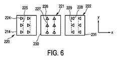
図6は、照明装置10によって使用され得る、光源224、226、228に係るグループ220、221、222の典型的な別の実施例を模式的に示している。図6に示されるように、3つのグループ220、221、222の光源224、226、228は、同一の形状を有しているが、その配向が異なっている。さらに、また図6において、破線225、227、229は、マイクロレンズが第2のグループ221の光源226に関して中心に配置されており、かつ、第1および第3のグループ220、222の光源224、228に関して非対称的に配置されていること、そして、この実施例において、光源224、226、228がそれぞれのサブストレート214、230、231の上に配置されていること、を示している。結果として生じるx位置に応じた積分強度が、図7において模式的に例示的に示されている。FIG. 6 schematically illustrates another exemplary embodiment of a
図7に示されるように、この実施例においても、積分強度は、光源の第1のグループ220の照明によって生じる第1の部分320、光源の第2のグループ221の照明によって生じる第2の部分321、および、光源の第3のグループ222の照明によって生じる第1の部分322を含んでいる。図7に示される積分強度は、x軸に平行な空間的な方向において実質的にM型であり、ここで、シーリング照明がシーリングラインのカーブした部分に沿って操縦されるときには、積分強度分布の一つ最大値は縮小され、特には、オフにされ得る。As shown in FIG. 7,also in this embodiment, the integrated intensity is the
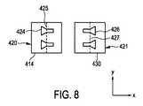
図8は、照明装置10によって使用され得る光源の異なるグループの典型的な更なる実施例を模式的に示す。両方のグループ420、421は、y軸に平行なラインにおいて配置された二つの実質的に円錐形状の光源424、426を含んでいる。ここで、光源424、426は、それぞれのサブストレート414、430の上に配置されており、異なるグループの光源は同一の形状を有しているが、それらは互いに関して180°回転されている。この実施例において、光源424、426の中心は、破線425、427によって示されるように、マイクロレンズの中心と一致している。Figure 8 is an exemplary further embodiment of the different groupsof light sourcesthat can be used by the
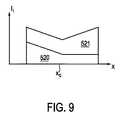
図9は、x座標に応じて、作業平面におけるy方向に沿って積分された強度である積分強度分布を模式的に例示的に示している。この実施例においても、得られる積分強度分布は実質的にM型であり、ここで、光源のグループ420、421のうち一つの強度を削減することによって、特には、グループ420、421のうち一つをオフにすることで、光源の第2のグループ421によって生じる部分521、または、光源の第1のグループ420によって生じる部分520を縮小、特には、積分強度分布から除去することができる。従って、この実施例においても、シーリングラインのカーブした部分にフィットするように、強度分布を変更することができる。9, depending on thex-coordinate, andanintegrated intensitydistribution is an intensity that is integrated along the ydirection inthe working planeis schematically shownillustratively. Also in this embodiment,the integrated intensity distributionobtained isRi substantially M-type Derby wherein, reducing one of the intensity of the
照明装置10は、従って、作業平面内において、シーリングラインに垂直なx方向においておおよそM型である積分強度分布を提供するように優先的に適合され、ここで、シーリングエレメントの中心においては熱除去が最少であるために、シーリングラインの中心では、より少ない強度が提供される。さらに、照明装置は、シーリング照明が、シールトラック、つまりシーリングラインに沿って丸みのある角の周りを移動するときに、M型形状の積分強度分布の少なくとも一つの肩における強度を削減するために、アドレス可能性を提供する。
光源は、優先的にはVCSELである。ここで、VCSELの異なるグループは、優先的に、対応する電流電源によって個々にアドレス可能であり、ターゲット平面、つまり作業平面、に対して結像する。VCSELは、図3、図6、および図8において模式的かつ典型的に示したように、異なる形状を有し得る。ここで、光源の結像の重ね合わせが、図5、図7、図9のそれぞれに示されている。異なるグループは、優先的に、個々の電力設定ができるように、かつ、強度プロファイルを要求通りに適合できるように、個々の電流電源を備えている。例えば、カーブでは、M型の積分強度分布の内側の肩に対してより低い電力を提供することができる。The light source is preferentially a VCSEL. Here, the different groups of VCSELs are preferentially individually addressable by the corresponding current supply and image with respect to the target plane, ie the working plane. The VCSEL may have different shapes, as schematically and typically shown in FIGS. 3, 6 and 8. Here, the superposition of the image formation of the light source is shown in FIGS. 5, 7, and 9, respectively. Different groups,preferentially, to allowindividual power settings, and to be compatiblewith the intensity profile asrequired, and a respective current source. For example, a curve can provide lower power to the inner shoulder of an M-typeintegrated intensity distribution.
図6と図7は、中央のディップと肩、特には最大値、との間のより極端な差を許容するコンフィグレーションを示している。さらに、これらの図に示された実施例においては、ただ一つのVCSEL形状が必要とされる。つまり、単純に、個々のグループに係るチップの配向が異なっている。図8と図9は、両方とも同一のVCSEL形状を使用する2つの異なるグループだけを用いた代替案を示す。この実施例において、それぞれのグループは、光源のリニアな配置を含んでおり、ここで、2つのグループのリニアな配置は、相互に平行である。このコンフィグレーションは、アドレスラインの数を削減し、特に、2つの列(two−row)のソリューションを提供する。ここでは、全ての電気的な接続が、外側に向かうワイヤボンディングを介して行われ得る。6 and 7 show a configuration that allows for a more extreme difference between the central dip and shoulder, especially the maximum value. Furthermore, in the embodiment shown in these figures, only one VCSEL shape is required. That is, theorientations of the chips related to individual groups are simply different. 8 and 9,shows thealternatives both with only two different groupsusing the same VCSELshape. In an embodiment ofthis, each group includes a linear arrangement of the light sources, wherein the linear arrangement of the two groups are parallel to each other. This configuration reduces the number of address lines, and in particular provides a two-row solution. Here, all electrical connections can be made via outward wire bonding.
照明装置は、さらに、光源のグループが測定温度に応じてコントロールユニット12によってコントロール可能であるように、作業平面における温度を測定するために、光源のグループに隣接して配置された、熱放射検出ユニットを含んでよい。このように、コントロールユニットが、測定温度に応じて光源の異なるグループに供給される電力をコントロールすることができるようにするために、熱放射検出ユニットによって測定された温度がコントロールユニット12に提供され得る。以降に、熱放射検出ユニットの好適な構成が、照明装置の更なる実施例610を参照して説明され、これは図3から図9に関して上記に説明された照明装置10の代わりに、シーリング装置1によって使用され得る。The illuminator further comprises thermal radiation detection arranged adjacent to the group of light sources for measuring the temperaturein the working plane so that the group of light sourcescan be controlled by the
照明装置610は、図10に典型的な例が模式的に示されているが、サブストレート614の上に配置されたVCSELのいくつかのグループ620を含んでいる。VCSELのグループ620のそれぞれは、優先的には、VCSELの2次元アレイである。VCSELのグループ620の間に、熱放射検出ユニット621が配置されている。光源のグループ620の間における、サブストレート614の上での熱放射検出ユニット621の配置について、図11において典型的な実施例が模式的に示されている。 The
図11に示されるように、この実施例において、照明装置は、光源のグループ620に係る3×3アレイを含んでいる。ここにおいて、y軸に平行なラインに沿って配置される光源の3つのグループは、y軸に平行である、光源のグループ620に係るそれぞれの列が、個々に、他の列とは独立してコントロールできるように、電源8と電気的に接続される。熱放射検出ユニット621は、シーリングラインに垂直なラインに沿った温度プロファイルを測定するために熱放射検出ユニット621が使用され得るように、x軸に平行なラインに沿って配置されている。コントロールユニット12は、所望の既定の温度プロファイルが得られるように、熱放射検出ユニット621によって測定された温度プロファイルに応じて、光源のグループ620の3つの異なる列が個別に電力を供給されるよう、電源8をコントロールするように適合され得る。特に、コントロールユニット12は、生成された温度プロファイルがシーリングラインに垂直な方向に沿ってできる限り均一であるように、電源8をコントロールするよう適合され得る。As shown in FIG. 11, in this embodiment, the lighting device includes a 3 × 3 array of light source groups 620. Here, three groups of light sourcesarranged along a line parallel to they-axis are parallel tothe y- axis, and each column of the
照明装置610は、さらに、オブジェクトがシールされる、作業平面上に光源のグループ620を結像させるためのイメージユニット616を含んでいる。結果として生じる作業平面における強度分布が、参照番号13によって示されている。図10、および、またさらに図4、図12、そして図13に示された光線は、説明目的のためだけに示されたものであって、正確な光線のパスを必ずしも示すものではない。The
レンズのような光学エレメントであるイメージユニット616と光源のグループ620は、光源の異なるグループの画像が作業平面においてオーバーラップするように配置されている。光源のグループ620と光学エレメント616は、従って、光源のグループ620が作業平面においてシャープに結像するようにではなく、わずかにぼやけた画像が作業平面において結像するように構成され得る。例えば、光学エレメント616は、光源のグループ620と光学エレメント616との間で作業平面上にシャープに平面を結像するように適合され得る。ここで、光源のグループ620と光学エレメント616との間の結像平面においては、光源の別のグループ620の照明がオーバーラップする。The
作業平面からの熱放射623は、光学エレメント616を横切り、熱放射検出ユニット621によって検出され得る。
このように、熱放射検出ユニットは、VCSELチップ間に配置されてよい。ここで、光源のグループによって生成される照明と熱放射は、同一のイメージ光学系を使用することができる。熱放射検出ユニットは、優先的には、実質的に熱放射だけがフォトダイオードによって検出されるようにするためにフォトダイオード(photodiode)とフォトダイオードの前面のフィルタを含む。フォトダイオードの代わりに、他の光感知デバイスを使用することもできる。Thus, the thermal radiation detection unit may be disposed between the VCSEL chips. Here, the illumination and thermal radiation generated by the group of light sources can use the same image optics. Thermal radiation detection unit Preferentially,substantiallyincluding a front filter of the photo diode (Photodiode) and photodiodesin order to only thermal radiation is detected by thephotodiode. Instead offull photodiode, it is also possible to use other optical sensing devices.
熱放射検出ユニットの波長感度は、優先的には、シーリングエレメント5から、特には、フリットシール材料からの熱放射を、レーザ放射から分離するために、レーザ発光よりもかなり長くなるように選択される。例えば、光源のグループは、約808nmの波長で発光し、かつ、熱放射検出ユニットは、1500nmより大きな波長を有する放射を測定するように適合されてよい。The wavelength sensitivity of the thermal radiation detection unit is preferentially selected to be considerably longer thanthe laser emissionin order to separate the thermal radiation from the sealing
熱放射検出ユニットは、優先的には、光源のグループに係る個々のアドレスラインに関連付けられる。ここで、シーリングラインを横切る、つまりシーリングラインに垂直な、温度プロファイルの測定、および、フィードバックループが提供され得る。フィードバックループは、優先的には、温度プロファイルを測定するための熱放射検出ユニット、コントロールユニット、および、電源を含んでいる。電源は、個々の電源グループを含んでおり、それらはコントロールユニット12が個々の電源グループと通信できるようにするためにコントロールユニット12と通信している。ここで、それぞれの電源グループは、図11に示される光源の3つのグループのそれぞれの列に対して接続されてよい。コントロールユニットは、平坦な温度プロファイルを実現するために、例えば、光源の外側のグループを通る電流を変更するように適合され得る。The thermal radiation detection unit is preferentially associated with individual address lines associated with a group of light sources. Here, a temperature profile measurement and a feedback loop can be provided across the sealing line, ie perpendicular to the sealing line. The feedback loop preferentially includes a thermal radiation detection unit for measuring the temperature profile, a control unit, and a power source. The power supply includes individual power supply groups that are in communication with the
以降では、図1から図9に関して上記に説明された照明装置10の代わりに、シーリング装置1によって使用され得る照明装置のさらなる実施例が、図12から15に関して例示的に模式的に説明される。In the following,further examples of lighting devices that may be used by the
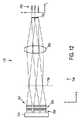
図12と図13は、照明装置710に係る異なる側面図を示している。これらの図でわかるように、この実施例においても、照明装置710は、サブストレート714の上に配置されている、光源のグループ720を含んでいる。光源のグループ720のそれぞれに係る照明は、個々のマイクロレンズのアレイ750、個々の円柱レンズ751、および、優先的には共通の光学レンズである共通の光学エレメント752によって結像される。マイクロレンズのアレイ750は、光源のグループのそれぞれの光源に対して一つのマイクロレンズが割り当てられるように、適合されている。マイクロレンズのアレイ750、円柱レンズ751、および、共通の光学エレメント752は、照明装置710のイメージユニット716を形成している。12 and 13 show different side views according to the
円柱レンズは、y軸とz軸が配置される平面を示している、図12に示される側面図において、光源のグループ720が、光学エレメント752によって作業平面へと結像される平面753へと結像されるように配置される。ここで、結果として生じる強度分布770は、図12の右側部分に模式的および典型的に示されるように、y方向に沿って比較的にシャープなピークを有する。さらに、円柱レンズ751は、x軸とz軸を含む平面を示している、図13に示される側面図において、円柱レンズ751が照明に影響しないように配置される。ここで、平面753において、光源の異なるグループ720の照明がx方向においてオーバーラップしている。図13の右側部分でわかるように、x方向に沿った強度分布770のプロファイルは、実質的にM型である。図12と図13において、参照番号713は、平面753に係る画像を示している。Cylindrical lens shows a plane y-axis and z-axis are arranged,and have contact to the side view shown in FIG.12, the
光源のグループ720とイメージユニット716は、照明装置710によって生成可能な強度分布770が数個の平行な照明ラインを有するように、適合される。ここで、実質的にM型の強度分布770を形成するために、各照明ライン内で、強度分布は、第1の最大値と第2の最大値を有し、第1の最大値と第2の最大値との間に強度ディップが位置する。The group of
図14は、サブストレート714上の光源のグループ720の上面図を模式的に例示的に示している。図14でわかるように、この実施例において、光源のグループ720のそれぞれは、強度分布770を要望通り変更するために、光源のグループ720のそれぞれが個々にコントロール可能であるように、電源8に個々に接続される。Figure 14 isa topview of a
図15は、図12から図14に関して上記に説明したように、照明装置710によって形成される強度分布770から結果として生じる積分強度分布を例示する。y位置に依存し、x方向に沿って強度分布770を積分することによって決定された積分強度分布763は、3つの比較的にシャープな最大値763を有し、これらの最大値763の間にはギャップが存在する。x位置に依存し、y方向に沿って積分された強度分布770である積分強度分布761は、中間に強度ディップを伴う、2つの外側の最大値を有し、従って、実質的にM型である。破線762で示されるように、積分強度分布は、特に、シーリング照明がシーリングラインのカーブした部分に沿って操縦される場合、光源のグループ720を適宜コントロールすることで外側の最大値を減少させることによって変更することができる。15, as described above with respect to FIG 14.FIG 12illustrates the integrated intensity distribution resulting from the
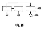
以降において、プロセスラインに沿ってオブジェクトをプロセスするためのプロセス方法、この実施例においては、シーリングラインに沿ってオブジェクトをシールするためのシール方法が、図16に示されるフローチャートを参照して例示的に説明される。Hereinafter, a process method for processing an object along a process line, in this embodiment, a sealing method for sealing an object along a sealing line, will beexemplified with reference to the flowchart shown in FIG. It isdescribed.
ステップ801において、ガラスフリットのようなシーリングエレメントの上に方向付けされるように、シーリング照明が照明装置によって提供される。ステップ801と同時に、照明装置とオブジェクト、および、従ってシーリングエレメントは、ステップ802において、移動ユニットによって、シーリングラインに沿ってシーリング照明が移動されるように、互いに関して移動される。ここで、シーリングエレメントは、シーリングラインに沿って配置されている。このようにして、シーリング照明は、オブジェクトをシールするために、例えば、ガラスフリットを溶かすように、シーリングラインに沿って操縦される。このシーリングプロセスの最中に、ステップ803において、放射検出エレメントを使用して、シーリングラインに対して垂直である空間的な方向に沿った温度プロファイルが測定される。ここで、測定された温度プロファイルは、シーリングラインに沿ったシーリング照明の移動、及び/又は、シーリングライン上の照明強度分布を測定された温度プロファイルに応じてコントロールするために、移動ユニットをコントロールするコントロールユニット、及び/又は、照明装置に電力を供給する電源に対して提供され得る。Step 801 smellTe so as to beonlyrectangular Mukozuke onthe sealing element, such asmoths Rasufurittoceiling illumination is provided by the illumination device. Simultaneously with
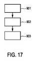
以降では、照明装置の製造のための製造方法に係る実施例について、図17に示されるフローチャートに関して、例示的に説明される。Hereinafter, an embodiment according to a manufacturing method for manufacturing a lighting device will beexemplarily described with reference to the flowchart shown in FIG.
ステップ901において、オブジェクトをシールする照明を生成するための光源のグループが提供される。ステップ902においては、シーリング照明を生成するために、オブジェクトがシールされる、作業平面の上に光源のグループを結像させるためのイメージユニットが提供される。ステップ903においては、照明装置を生成するために、光源のグループとイメージユニットが組み立てられる。強度分布が空間的積分方向において積分された場合に、結果として生じる積分強度分布が強度ディップを有するように構成される強度分布を伴って、シーリング照明が作業平面において生成可能であるように、並びに、強度分布を変更するために、光源の一つ又は数個のグループが、他のグループとは独立してコントロール可能であるように、光源のグループとイメージユニットが構成される。In
シーリング装置は、ディスプレイ、特には、有機発光ダイオード(OLED)ディスプレイを、生産において、密封してシールするように適合され得る。この目的のために、シーリングエレメントは、照明装置によって提供されるシーリング照明によって進行的に溶かされる、ディスプレイの縁に近いガラスフリットに係る約2mm幅のトレースであり得、全輪郭が、それぞれのディスプレイ、および、従って、シーリングエレメントとシーリング照明の相互に対する機械的な移動を介して、優先的にプロセスされる。シーリングプロセスの最中は、カーブの内側でのより遅い進行スピードが、オーバーヒートと燃焼につながり得るため、特に丸みをおびたディスプレイの縁付近で、シーリングエレメントにかかる温度分布が重要になり得る。シーリングエレメントの下の反射アドレスラインが交差する場合も、数千回起こり得るものであるが、反射がシーリングエレメントのオーバーヒートを生じさせ得る。上記のシーリング装置は、従って、優先的には、仕立てられ、アドレス可能で、かつ、コントロール可能な強度分布を提供する。The sealing device can be adapted to seal and seal displays, in particular organic light emitting diode (OLED) displays, in production. For this purpose, the sealing elementis melted in progressively by a sealing illumination provided by the illumination device, OhRi obtained in trace about 2mm wide according to the glass frit near the edge of thedisplay, all the contours, respectively display, and,therefore, through a mechanical movementfor mutualsheet over the ring element and the sealing illumination is preferentially process. During the sealing process,a slower progression speed inside the curve, because that can lead to overheating and burning, display edges around the that particular rounded, the temperature distributionaccording to the sealing elementcan be important. Sometimes antiIA dress line below thesheet-ringelements intersect, but it is capable stiffness several thousandKaiOkoshi, reflections can cause overheating of the sealing element. The sealing device described above thus preferentially provides a tailored, addressable and controllable intensity distribution.
特に、シーリング装置は、優先的には、シーリングラインに沿って移動することができるアドレス可能なモジュールに基づく高電力VCSELソリューションを提供する。強度分布は、VCSELの光学的特性を使用して仕立てることができる。ここでは、シーリングトラックに沿った、つまりシーリングラインに沿った、異なる必要性を扱うために、異なるVCSELのパターンが重ね合わせられる。VCSELは、電気的接続の数および異なるVCSELチップに対する要求が最小化されるように、構成され得る。さらに、シーリング装置は、特に図10と図11に関して上記に説明したように、統合された高温測定に基づいて強度分布をコントロールするように適合され得る。In particular, the sealing device preferentially provides a high power VCSEL solution based on addressable modules that can move along the sealing line. The intensity distribution can be tailored using the optical properties of the VCSEL. Here, different VCSEL patterns are superimposed to handle different needs along the sealing track, ie along the sealing line.VCSEL, as required forthe number and different VCSELchipelectrical connections are minimized, can be configured. Further, the sealing device may be adapted to control the intensity distribution based on integrated pyrometry, particularly as described above with respect to FIGS.
照明装置に係る光源のグループは、優先的には、一つ又は数個のサブストレートが発光領域と非発光領域を含むように、一つ又は数個のサブストレートの上に配置される。非発光領域は、作業平面から後方反射された照明が作業平面に戻るように反射されないように、非発光領域にあたる照明を吸収し、及び/又は、散乱させるように適合され得る。 The group of light sources according to the illuminating device is preferentially arranged on one or several substrates so that one or several substrates comprise a light emitting area and a non-light emitting area. The non-light emitting area may be adapted to absorb and / or scatter the illumination that falls on the non-light emitting area so that the illumination reflected back from the work plane is not reflected back to the work plane.
特に、シーリング照明が向けられるターゲット領域の部分は反射性であり得るため、照射されたパワーの多くの部分は、一般的に、ターゲットから後方反射され得る。しかしながら、シーリング装置、特に照明装置は、例えば、シールされるべきディスプレイ上の、望まれない場所に戻っていく照明の量を削減するように適合されてよい。このように、シーリング装置に係る照明装置は、例えば、シールされるべきディスプレイからの後方反射が「ゴースト画像」を生じない方法で設計され得る。例えば、非発光領域は、黒色であり、発光領域に関して傾いており、または、任意の方向に照明を散乱するように適合されてよい。つまり、例えば、発光領域の外側のVCSELチップの部分は黒色であり、散乱し、または、所定の角度で傾いていてよい。レーザモジュール、つまり照明装置も、作業平面によって直接的に反射された照明がレーザモジュールの中に戻るよう方向付けされないように、作業平面に関して傾いてよい。In particular,sincethe portion of the target area to sealing illumination is directedmay be areflectionof, many parts of the irradiated power can generally be reflected back from the target. However, the sealing device, in particular the lighting device, may be adapted to reduce the amount of illumination returning to an undesired location, for example on the display to be sealed. Thus, the lighting device according to the sealing device can be designed, for example, in such a way that the back reflection from the display to be sealed does not produce a “ghost image”. For example, the non-light emitting area may be black, tilted with respect to the light emitting area, or adapted to scatter illumination in any direction. That is, for example, theportion of the VCSELchip outside the light emitting region may be black, scattered, or tilted at a predetermined angle. The laser module, i.e. the lighting device, may also be tilted with respect to the working plane so that the illumination reflected directly by the working plane is not directed back into the laser module.
上記の実施例において、光源、特にVCSELは、所定の形状を有するが、他の実施例において、光源は他の形状を有してもよい。例えば、全て又はいくつかの光源は、蝶ネクタイ形状を有してよい。さらに、例えば、図8で示した所定の形状の代わりに、この図で示された光源は、長方形および三角形光源で置き換えることができる。ここで、三角形光源に関して、マイクロレンズの中心は三角形光源の終端と一致しており、そして、長方形光源に関して、マイクロレンズの中心は長方形光源の中心と一致している。さらに、図8において、およそ円錐形状の光源の代わりに、異なる形状の、他の光源が使用され得る。ここで、それらの異なる形状の光源は、y方向においてより大きな幅をもった第1の終端とy方向においてより小さな幅をもった対向する第2の終端を有している。 In the above embodiments, the light source, particularly the VCSEL, has a predetermined shape, but in other embodiments, the light source may have other shapes. For example, all or some of the light sources may have a bow tie shape. Further, for example, instead of the predetermined shape shown in FIG. 8, the light sources shown in this figure can be replaced with rectangular and triangular light sources. Here, for a triangular light source, the center of the microlens coincides with the end of the triangular light source, and for a rectangular light source, the center of the microlens coincides with the center of the rectangular light source. Further, in FIG. 8, other light sources of different shapes may be used instead of the approximately conical light source. Here, the differently shaped light sources have a first end having a larger width in the y direction and an opposing second end having a smaller width in the y direction.
上記の実施例において、イメージユニットは、作業平面の中に光源を結像させるための所定の光学的構成を有しているが、イメージユニットは、また、他の光学的構成を有してもよい。例えば、図10で示したイメージユニットは、追加的にマイクロレンズを含んでよい。ここで、それぞれのマイクロレンズは、それぞれの光源に対して割り当てられ、そして、光学エレメント616、特にレンズ616は、近接場の代わりに、コリメートするマイクロレンズの平面を結像するように構成されてよい。一般的に、焦点合わせは、作業平面における、個々の光源間または光源の個々のグループ間の視認できるギャップを避けるために、やや焦点がずれていてよい。In the above embodiment, the image unit has a predetermined optical configuration for imaging the light source in the work plane, but the image unit may also have other optical configurations. Good. For example, the image unit shown in FIG. 10 may additionally include a microlens. Here, each microlens is allocated to each of the light sources, and
シーリング装置は、シーリングラインを横切る個々にアドレス可能な光源のグループに加えて、シーリングラインに沿って異なるセグメントも使用できるように、適合されてよい。これにより、シーリングの際の加熱プロセスの温度カーブをコントロールすることができ、そして、シーリング材料のあらゆる個々の場所に付与されるエネルギ量を低下させるため、つまり例えば、下層のアルミ製のアドレスラインのような下層の反射アドレスラインによって引き起こされる可能性のあるオーバーヒートを考慮するために、追加的な自由度が可能となる。ガラスまたはプラスチック材料のような熱伝導率が低い材料の場合、温度上昇は、一般的に付与された累積のエネルギによって決まる。ここにおいて、シーリングラインの方向に沿って温度を構成するために、シーリングラインに沿って個別にコントロール可能な異なるセグメントによって提供される自由度が使用され得る。電気的な接触を促進するため、または、光源のグループ間に上述の熱放射検出ユニットのようなセンサエレメントを配置できるようにするために、シーリングラインに沿って、光源のグループ間、つまり、例えばVCSELチップ間に、ギャップが存在してよい。全てのグループの電気的なアドレスは、最大の自由度を提供するために、個別のものであってよい。しかしながら、電気的な接触を促進するために、いくつかのグループを結合することもできる。Sealing device, in addition to the groups of individuallyaddressable light sourcesacross the sealing line, so that it can be useddifferent segments along the sealing line, it may be adapted. Thus, it is possible to control the temperature curve of thepressurized thermal process during sealing, and,to reduce the amount of energy applied to any individual location of the sealing material, i.e. for example, the lower layer of aluminum address lines to account for the lower overheating which may be caused by reflections address lines, such as,that Do allow additional degrees offreedom. When the thermal conductivity, such asglass or plastic material of a low material, a temperature rise is determined by the energy of generallygranted accumulated. Here, the degrees of freedom provided by the different segments individually controllable along the sealing line can be used toconfigure the temperature along the direction of the sealing line.In order to facilitate electrical contact or to be able to arrange sensor elements such as the above-mentioned thermal radiation detection units between groups of light sources, along a sealing line, between groups of light sources, for example between the VCSEL chip,not good and there is agap. Electrical address of a group ofall hands, in order to provide maximum flexibility, may be of individual. However, several groups can be combined to facilitate electrical contact.
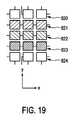
上記の実施例において、光源のグループは所定の構成に配置され、かつ、所定のやり方で電気的に接続されているが、他の実施例において、光源のグループは他の構成で配置されてよく、そして、電源に対する電気的な接続も異なってよい。例えば、図18で模式的および典型的に示されるように、光源の数個のグループ920は、特に、実質的に円に沿って、または、正方形に沿って、対称的に配置されてよい。ここで、光源のグループ920のそれぞれは、個別にアドレス可能である。これにより、レーザヘッドを回転することなく、つまり照明装置を回転させることなく、カーブに沿ってシーリングラインを移動することができる。図19は、光源のグループの更なる可能な構成について、典型的な例を模式的に示している。この実施例において、構成は、光源のグループの数個のセット820・・・824を含んでおり、それぞれのセットの中では、光源のグループがx方向に平行なラインに沿って配置されており、異なるセットの異なるラインは相互に平行である。光源のグループの第1のセット824と最後のセット820は、それらが個別にコントロール可能であるように、y方向に関して、電源に対して電気的に接続されている。一方、光源のグループの他のセット821、822、823は、同一のセットの光源のグループは共通してコントロール可能であり、かつ、異なるセットは個別にコントロール可能であるように、電気的に接続されている。従って、この実施例において、グループに関する個別のアドレスは、第1のセット824と最後のセット820に対してだけ実現されている。そうした構成および電気的な接続によって、例えば、ワイヤボンディングによるエッジからの全ての個々の部分に対するアクセスを可能にしている。In the above embodiments, the groups of light sources are arranged in a predetermined configuration and are electrically connected in a predetermined manner, but in other embodiments, the groups of light sources may be arranged in other configurations. And the electrical connection to the power supply may be different. For example, as schematically and typically shown in FIG. 18,
光源のグループの一つ又は数個のグループを個別にコントロールするために、電源は、個別の電源ユニットを含んでよく、それらは個別にコントロールされる光源のそれぞれのグループと電気的に接続される。In order to individually control one or several groups of light sources, the power supply may include individual power supply units, which are electrically connected to each group ofindividually controlled light sources. .
上記の実施例において、プロセス装置は、シールのためのシーリング装置、例えば、ガラスフリットのようなシーリングエレメントを使用したOLEDディスプレイであるが、プロセス装置は、また、シーリング照明を必要とする、別のシーリング動作を実行するシーリング装置であってもよい。例えば、シーリング装置は、シーリングエレメントを必要としないで、直接的にオブジェクトをシールするように適合されているものとして提供されてよい。さらに、シーリング装置は、他のオブジェクトをシールするように適合されているものとして提供されてよい。一般的に、シーリング装置は、例えば、シールされるべきオブジェクトの縁に沿って、所定の強度プロファイルが適用され、進行される、多くのシーリングアプリケーションのために使用されるように適合されているものとして提供されてよい。例えば、シーリング装置は、OLED照明システム、光電池セル、食品、薬、などのプラスチック包装、をシールするように適合され得る。In the above example, the process device is a sealing device for sealing, for example an OLED display using a sealing element such as a glass frit, but the process device also requires another ceiling illumination. It may be a sealing device that performs a sealing operation. For example, the sealing device may be provided as being adapted to seal objects directly without the need for sealing elements. Furthermore, the sealing device may be provided as being adapted to seal other objects. In general, the sealing device is adapted to be used for many sealing applications,e.g. where a predetermined intensity profile is applied and advanced along the edges of the object to be sealed .not good is providedas. Forexample, the sealing device, OLED lighting systems, photovoltaic cells, food may be adapted to seal drugs, plastic packaging, such as.
プロセス装置は、また、シーリングプロシージャではない、別のプロシージャを実行するように適合されてもよい。例えば、プロセス装置は、照明装置によって提供される照明により材料が溶かされる、はんだ付け、または、溶接プロシージャを実行するように適合されてもよい。The process device may also be adapted to perform another procedure that is not a sealing procedure. For example, process equipment,the material is melted by the illumination provided by the illumination device, soldering, or,but it may also be adapted to perform the welding procedure.
図面、明細書、および添付の特許請求の範囲を研究すれば、クレームされた本発明の実施において、当業者によって、開示された実施例に対する他の変形が理解され、もたらされ得る Upon studying the drawings, the specification and the appended claims, other variations to the disclosed embodiments can be realized and effected by those skilled in the art in practicing the claimed invention.
請求項において、用語「含む(“comprising“」は、他のエレメントまたはステップを排除するものではなく、不定冠詞「一つの(”a“または”an“)」は、複数を排除するものではない。 In the claims, the term “comprising” does not exclude other elements or steps, and the indefinite article “a” or “an” does not exclude a plurality. .
単一のユニットまたはデバイスは、請求項で述べられる数個のアイテムに係る機能を満たし得る。特定の手段が、互いに異なる従属請求項の中で引用されているという事実だけでは、これらの手段の組合せが有利に使用され得ないことを示すものではない。A single unit or device may fulfill the functions of several items stated in the claims. Certainmeasures, only the fact that are cited in different dependent claimseach other physician does not indicate that a combination of these measures can not be used to advantage.
シーリング方法に従ったシーリング装置のコントロールは、コンピュータプログラムのプログラムコード手段として、及び/又は、専用のハードウェアとして実施されてよい。 Control of the sealing device according to the sealing method may be implemented as program code means of a computer program and / or as dedicated hardware.
コンピュータプログラムは、光記録媒体もしくはハードウェアと供に、またはハードウェアの一部として提供される半導体媒体といった、好適な媒体上に記録され、配布され得る。しかし、インターネット、または他の有線もしくは無線の電子通信システムを介するといった、他の形式においても配布され得る。ComputingTup program is to test the optical recording medium or hardware, or such as a semiconductor medium which is provided as part of the hardware, is recorded on a suitable medium, it may be distributed. However, it can also be distributed in other formats, such as via the Internet or other wired or wireless electronic communication systems.
請求項におけるいかなる参照番号も、発明の範囲を限定するものと解釈されるべきではない。 Any reference signs in the claims should not be construed as limiting the scope.
本発明は、オブジェクトをプロセスするためのプロセス照明を提供する照明装置に関する。光源のグループは、オブジェクトをプロセスするための照明を生成する。ここで、光源のグループは、プロセス照明を生成するためのイメージユニットによって、作業平面上に結像される。結果として生じる強度分布は、空間的積分方向において強度分布が積分される場合に、結果として生じる強度分布が強度ディップを有するように、構成されている。ここで、光源の一つ又は数個のグループは、光源の他のグループから独立して、積分強度分布を変更するためにコントロール可能である。これにより、それに沿ってオブジェクトがプロセスされる、特にシールされるプロセスラインに垂直に、オブジェクトが比較的均一にプロセスされるように、プロセス装置において照明装置を使用することができ、これによって、オブジェクトをプロセスする品質が改善される。The present invention relates to a lighting device that provides process lighting for processing objects. A group of light sources generates illumination for processing the object. Here, the group of light sources is imaged on the work plane by an image unit for generating process illumination. The resulting intensity distribution is configured such that when the intensity distribution is integrated in the spatialintegration direction, the resulting intensity distribution has an intensity dip. Here,one or several groups of light sources can be controlled to change theintegrated intensity distribution independently of other groups of light sources.This ensures thatit objectsalongis a process, perpendicular to the process line to be particularly sealed,as the objectis relatively uniformprocess, it is possible to use a lighting device in the process device, whereby The quality of processing objects will be improved.
Claims (12)
Translated fromJapanese前記オブジェクトをプロセスするための照明を生成する光源のグループと、
前記オブジェクトがシールされるべき作業平面の上に前記光源のグループを結像させ、それにより前記プロセス照明を生成するイメージユニットと、を含み、
前記光源のグループと前記イメージユニットは、前記作業平面において、前記プロセス照明が強度分布を伴って生成可能なように適合され、
前記強度分布は、空間的積分方向において積分された場合に、結果として生じる積分強度分布が強度ディップを有するように構成され、
前記積分強度分布を変更するために、前記光源の一つ又は数個のグループは、前記光源の他のグループとは独立してコントロール可能であり、
前記光源のグループと前記イメージユニットは、前記積分強度分布が、前記光源のグループの一つのグループによって提供される照明により生じる第1の最大値と前記光源のグループの別のグループによって提供される照明により生じる第2の最大値とを有するように適合され、
前記第1の最大値と前記第2の最大値との間に前記強度ディップが位置し、
前記シーリングエレメントがカーブしたシーリングラインに沿って配置される場合に前記シーリングエレメントが均一に照明されるよう、前記第1の最大値と前記第2の最大値のうち少なくとも一つの位置における積分強度がそれぞれ削減可能であるように、前記第1の最大値を生じている少なくとも一つの前記グループと前記第2の最大値を生じている前記別のグループが個々にコントロール可能である、
照明装置。A lighting device that provides process illumination for sealing an object including a sealing element for sealing the object along a sealing line:
A group of light sources that generate illumination for processing the object;
An image unit that images the group of light sources onto a work plane where the object is to be sealed, thereby generating the process illumination;
The group of light sources and the image unit are adapted to allow the process illumination to be generated with an intensity distribution in the work plane;
The intensity distribution is configured such that when integrated in the spatial integration direction, the resulting integrated intensity distribution has an intensity dip;
In order to change the integrated intensity distribution, one or several groups of the light sources can be controlled independently of other groups of the light sources;
The light source group and the image unit have an illumination intensity provided by another group of the light source group and a first maximum value where the integrated intensity distribution is caused by illumination provided by one group of the light source group. Adapted to have a second maximum produced by
The intensity dip is located between the first maximum value and the second maximum value;
The integrated intensity at at least one position of the first maximum value and the second maximum value is such that the sealing element is uniformly illuminated when the sealing element is disposed along a curved sealing line. Each of the group producing the first maximum value and the other group producing the second maximum value are individually controllable such that each can be reduced;
Lighting device.
請求項1に記載の照明装置。At least one group of the light sources is individually controllable so that the depth of the intensity dip can be changed.
The lighting device according to claim 1.
少なくとも一つの前記照明ラインにおいて、前記強度分布は第1の最大値と中間により低い強度を伴う第2の最大値とを有する、
請求項1に記載の照明装置。The group of light sources and the image unit are adapted such that the intensity distribution that can be generated by the illuminating device has several parallel illumination lines;
In at least one of the illumination lines, the intensity distribution has a first maximum value and a second maximum value with a lower intermediate intensity.
The lighting device according to claim 1.
請求項1に記載の照明装置。At least two groups of light sources have different shapes;
The lighting device according to claim 1.
少なくとも一つの光源について、前記マイクロレンズの中心が前記光源の中心と一致しないように、前記マイクロレンズが前記光源に関して非対称的に配置される、
請求項1に記載の照明装置。The image unit includes a microlens assigned to the light source such that each microlens is used to image a respective light source;
For at least one light source, the microlens is arranged asymmetrically with respect to the light source such that the center of the microlens does not coincide with the center of the light source;
The lighting device according to claim 1.
請求項1に記載の照明装置。The image unit is adapted to image the group of light sources onto the work plane such that images of different groups of light sources overlap in the work plane;
The lighting device according to claim 1.
請求項1に記載の照明装置。The illuminating device is further arranged adjacent to the group of light sources for measuring the temperature in the working plane so that the group of light sources can be controlled according to the measured temperature by a control unit. Including two thermal radiation detection units,
The lighting device according to claim 1.
請求項1に記載の照明装置。One or several groups of the light sources can be controlled independently of other groups of the light sources so that the intensity distribution can be changed in two different spatial directions;
The lighting device according to claim 1.
前記非発光領域は、前記作業平面から後方反射された照明が前記作業平面に戻るように反射されないように、前記非発光領域にあたる照明を吸収し、及び/又は、散乱させるように適合される、
請求項1に記載の照明装置。The light source group is disposed on one or several substrates such that one or several substrates include a light emitting region and a non-light emitting region,
The non-light emitting area is adapted to absorb and / or scatter the illumination that falls on the non-light emitting area so that illumination reflected back from the work plane is not reflected back to the work plane;
The lighting device according to claim 1.
プロセス照明を提供するための請求項1に記載の前記照明装置と、
前記プロセス照明が前記プロセスラインに沿って移動されるように、前記照明装置と前記オブジェクトとを互いに関して移動するための移動ユニットと、
を含む、プロセス装置。A process device for sealing an object including a sealing element for sealing the object along aprocess line , comprising:
The lighting device of claim 1 for providing process lighting;
A moving unit for moving the lighting device and the object relative to each other such that the process lighting is moved along the process line;
Including process equipment.
請求項1に記載の前記照明装置によってプロセス照明を提供するステップと、
前記プロセス照明が前記プロセスラインに沿って移動されるように、前記照明装置と前記オブジェクトとを互いに関して移動するステップと、
を含み、
前記プロセス照明は、前記積分強度分布が、前記光源のグループの一つのグループによって提供される照明により生じる第1の最大値と前記光源のグループの別のグループによって提供される照明により生じる第2の最大値とを有するように前記光源のグループと前記イメージユニットをコントロールすることによって提供され、
前記第1の最大値と前記第2の最大値との間に強度ディップが位置し、
前記シーリングエレメントがカーブしたシーリングラインに沿って配置される場合に前記シーリングエレメントが均一に照明されるよう、前記第1の最大値と前記第2の最大値のうち少なくとも一つの位置における積分強度がそれぞれ削減可能であるように、前記第1の最大値を生じている少なくとも一つの前記グループと前記第2の最大値を生じている前記別のグループが個々にコントロール可能である、
プロセス方法。A process method for sealing an object including a sealing element for sealing the object along a process line, comprising:
Providing process illumination by the lighting device of claim 1;
Moving the lighting device and the object relative to each other such that the process illumination is moved along the process line;
Including
The process illumination includes a second maximum produced by the illumination provided by another group of the light source group and a first maximum value caused by the illumination provided by one group of the light source group. Provided by controlling the group of light sources and the image unit to have a maximum value,
An intensity dip is located between the first maximum value and the second maximum value,
The integrated intensity at at least one position of the first maximum value and the second maximum value is such that the sealing element is uniformly illuminated when the sealing element is disposed along a curved sealing line. Each of the group producing the first maximum value and the other group producing the second maximum value are individually controllable such that each can be reduced;
Process method.
コンピュータプログラム。12. A computer program for sealing an object on a work plane, wherein when the computer program is executed on a computer that controls the process device, the process device according to claim 10 and the process according to claim 11 are executed. Including program code means for performing the steps of the method,
Computer program.
Applications Claiming Priority (3)
| Application Number | Priority Date | Filing Date | Title |
|---|---|---|---|
| US201261625136P | 2012-04-17 | 2012-04-17 | |
| US61/625,136 | 2012-04-17 | ||
| PCT/IB2013/052905WO2013156909A1 (en) | 2012-04-17 | 2013-04-12 | Lighting apparatus |
Publications (2)
| Publication Number | Publication Date |
|---|---|
| JP2015525135A JP2015525135A (en) | 2015-09-03 |
| JP6218806B2true JP6218806B2 (en) | 2017-10-25 |
Family
ID=48577167
Family Applications (1)
| Application Number | Title | Priority Date | Filing Date |
|---|---|---|---|
| JP2015506335AActiveJP6218806B2 (en) | 2012-04-17 | 2013-04-12 | Lighting device |
Country Status (6)
| Country | Link |
|---|---|
| US (1) | US9096042B2 (en) |
| EP (1) | EP2838688B1 (en) |
| JP (1) | JP6218806B2 (en) |
| CN (1) | CN104220208B (en) |
| RU (1) | RU2635651C2 (en) |
| WO (1) | WO2013156909A1 (en) |
Families Citing this family (6)
| Publication number | Priority date | Publication date | Assignee | Title |
|---|---|---|---|---|
| JP6218806B2 (en)* | 2012-04-17 | 2017-10-25 | コーニンクレッカ フィリップス エヌ ヴェKoninklijke Philips N.V. | Lighting device |
| US9553423B2 (en) | 2015-02-27 | 2017-01-24 | Princeton Optronics Inc. | Miniature structured light illuminator |
| US9830789B2 (en)* | 2015-12-29 | 2017-11-28 | Honeywell International Inc. | Ceiling mount intrusion detector with arbitrary direction detection capability |
| DE102016107595B4 (en)* | 2016-04-25 | 2018-12-13 | Precitec Gmbh & Co. Kg | Beam shaping optics for material processing by means of a laser beam and device with the same |
| EP3598591A1 (en)* | 2018-07-17 | 2020-01-22 | Koninklijke Philips N.V. | Laser arrangement with reduced building height |
| DE102021116359A1 (en) | 2021-06-24 | 2022-12-29 | CellForm IP GmbH & Co. KG | Process for processing workpieces |
Family Cites Families (28)
| Publication number | Priority date | Publication date | Assignee | Title |
|---|---|---|---|---|
| RU2034687C1 (en)* | 1992-06-08 | 1995-05-10 | Александр Михайлович Любченко | Installation for laser treatment of parts |
| US5961859A (en)* | 1997-10-23 | 1999-10-05 | Trw Inc. | Method and apparatus for monitoring laser weld quality via plasma size measurements |
| JP2002323309A (en)* | 2001-04-25 | 2002-11-08 | Anritsu Corp | Rotation angle detector for diffraction part |
| JP2002335046A (en)* | 2001-05-10 | 2002-11-22 | Hamamatsu Photonics Kk | Semiconductor laser array |
| JP2003121777A (en)* | 2001-10-18 | 2003-04-23 | Sony Corp | Illuminator using lens array and picture display device |
| JP4347545B2 (en) | 2002-06-28 | 2009-10-21 | 株式会社 液晶先端技術開発センター | Crystallization apparatus and crystallization method |
| JP4347546B2 (en) | 2002-06-28 | 2009-10-21 | 株式会社 液晶先端技術開発センター | Crystallization apparatus, crystallization method and optical system |
| TWI301295B (en)* | 2002-07-24 | 2008-09-21 | Adv Lcd Tech Dev Ct Co Ltd | Crystallization apparatus, crystallization method, thim film transistor and display apparatus |
| RU2240906C1 (en)* | 2003-06-10 | 2004-11-27 | Открытое акционерное общество "Раменское приборостроительное конструкторское бюро" | Method for laser welding of precision parts |
| JP2005086027A (en)* | 2003-09-09 | 2005-03-31 | Seiko Epson Corp | Surface emitting semiconductor laser, optical module, and optical transmission device |
| JP2005161362A (en)* | 2003-12-02 | 2005-06-23 | Seiko Epson Corp | Joining method, joining structure and joining apparatus |
| DE102004016669B3 (en)* | 2004-01-07 | 2005-10-13 | Daimlerchrysler Ag | Method for testing a laser weld seam |
| JP4877906B2 (en)* | 2005-08-05 | 2012-02-15 | 麒麟麦酒株式会社 | Method for producing sealed container for beverage or food |
| JP5145673B2 (en)* | 2006-08-30 | 2013-02-20 | 住友電気工業株式会社 | Laser processing method and laser processing apparatus |
| JP5089212B2 (en)* | 2007-03-23 | 2012-12-05 | シャープ株式会社 | LIGHT EMITTING DEVICE, LED LAMP USING THE SAME, AND METHOD FOR MANUFACTURING LIGHT EMITTING DEVICE |
| CN101563643B (en)* | 2007-03-30 | 2012-05-09 | 夏普株式会社 | Apparatus and method for manufacturing display panel, and display panel manufactured by the method |
| KR100937864B1 (en) | 2008-03-14 | 2010-01-21 | 삼성모바일디스플레이주식회사 | Frit sealing system |
| JP2009269083A (en)* | 2008-05-12 | 2009-11-19 | Toshiba Corp | Laser beam machining apparatus and method, and manufacturing method of flat panel display |
| US9229024B2 (en)* | 2009-01-20 | 2016-01-05 | Koninklijke Philips N.V. | Method for adjusting a self mixing laser sensor system for measuring the velocity of a vehicle |
| DE102009037404C5 (en) | 2009-08-13 | 2019-01-10 | Multivac Sepp Haggenmüller Se & Co. Kg | Laser sealing of packaging |
| EP2478602B1 (en)* | 2009-08-20 | 2014-12-10 | Koninklijke Philips N.V. | Laser device with configurable intensity distribution |
| CN102959811B (en) | 2009-12-19 | 2016-06-29 | 三流明公司 | For combining the system and method for the laser array for numeral output |
| KR101243920B1 (en) | 2010-01-07 | 2013-03-14 | 삼성디스플레이 주식회사 | Laser beam irradiation apparatus for substrate sealing, substrate sealing method, and manufacturing method of organic light emitting display device using the same |
| KR101097327B1 (en)* | 2010-01-07 | 2011-12-23 | 삼성모바일디스플레이주식회사 | Laser beam irradiation apparatus for substrate sealing and manufacturing method of organic light emitting display device using the same |
| JP6062140B2 (en)* | 2010-08-24 | 2017-01-18 | 浜松ホトニクス株式会社 | Dissimilar material joining method |
| JP6320938B2 (en)* | 2012-02-16 | 2018-05-09 | フィリップス ライティング ホールディング ビー ヴィ | Lighting configuration apparatus and method using distance sensor |
| JP6218806B2 (en)* | 2012-04-17 | 2017-10-25 | コーニンクレッカ フィリップス エヌ ヴェKoninklijke Philips N.V. | Lighting device |
| RU2644599C2 (en)* | 2012-04-20 | 2018-02-13 | Конинклейке Филипс Н.В. | Light installation for providing light for object processing |
- 2013
- 2013-04-12JPJP2015506335Apatent/JP6218806B2/enactiveActive
- 2013-04-12WOPCT/IB2013/052905patent/WO2013156909A1/enactiveApplication Filing
- 2013-04-12EPEP13727360.3Apatent/EP2838688B1/enactiveActive
- 2013-04-12RURU2014145868Apatent/RU2635651C2/ennot_activeIP Right Cessation
- 2013-04-12CNCN201380020511.3Apatent/CN104220208B/enactiveActive
- 2013-04-12USUS14/394,754patent/US9096042B2/enactiveActive
Also Published As
| Publication number | Publication date |
|---|---|
| CN104220208A (en) | 2014-12-17 |
| EP2838688B1 (en) | 2019-09-18 |
| JP2015525135A (en) | 2015-09-03 |
| CN104220208B (en) | 2017-03-15 |
| RU2014145868A (en) | 2016-06-10 |
| US9096042B2 (en) | 2015-08-04 |
| RU2635651C2 (en) | 2017-11-14 |
| WO2013156909A1 (en) | 2013-10-24 |
| EP2838688A1 (en) | 2015-02-25 |
| US20150108371A1 (en) | 2015-04-23 |
Similar Documents
| Publication | Publication Date | Title |
|---|---|---|
| JP6218806B2 (en) | Lighting device | |
| US11320666B2 (en) | Integrated structured-light projector | |
| KR20200043952A (en) | Projectors of structured light | |
| US9825425B2 (en) | Integrated structured-light projector comprising light-emitting elements on a substrate | |
| JP5744001B2 (en) | Optoelectronic semiconductor components and display devices | |
| CN107073838A (en) | Apparatus and method for manufacturing three-dimensional objects | |
| CN117878010A (en) | Laser assisted bonding system and method for manufacturing semiconductor device | |
| JP6674592B1 (en) | Method and apparatus for manufacturing flexible light emitting device | |
| EP2267534A1 (en) | Illumination system | |
| CN109270699A (en) | A kind of VCSEL laser speckle projector | |
| CN109093251B (en) | A laser packaging device and packaging method | |
| CN105336876B (en) | Package sealing with laser glass packages package system and method for packing | |
| JP2013021248A (en) | Light emitting module | |
| JP7051991B2 (en) | Semiconductor device | |
| JP2016066754A (en) | Light source device | |
| US9872395B2 (en) | Component crimping apparatus | |
| JP6664037B1 (en) | Method and apparatus for manufacturing flexible light emitting device | |
| CN203477930U (en) | Light illumination device | |
| CN104396101B (en) | Laser Modules with Homogenous Linear Intensity Profiles | |
| JP2019168328A (en) | Method for inspecting semiconductor device and method for manufacturing semiconductor device | |
| KR100850808B1 (en) | Sealing material for glass substrate package Sealing method Sealing system | |
| JP2009123924A (en) | Ultraviolet irradiation apparatus | |
| TWM579820U (en) | A VCSEL laser device |
Legal Events
| Date | Code | Title | Description |
|---|---|---|---|
| A621 | Written request for application examination | Free format text:JAPANESE INTERMEDIATE CODE: A621 Effective date:20160408 | |
| A977 | Report on retrieval | Free format text:JAPANESE INTERMEDIATE CODE: A971007 Effective date:20170223 | |
| A131 | Notification of reasons for refusal | Free format text:JAPANESE INTERMEDIATE CODE: A131 Effective date:20170228 | |
| A521 | Request for written amendment filed | Free format text:JAPANESE INTERMEDIATE CODE: A523 Effective date:20170420 | |
| A131 | Notification of reasons for refusal | Free format text:JAPANESE INTERMEDIATE CODE: A131 Effective date:20170613 | |
| A521 | Request for written amendment filed | Free format text:JAPANESE INTERMEDIATE CODE: A523 Effective date:20170816 | |
| TRDD | Decision of grant or rejection written | ||
| A01 | Written decision to grant a patent or to grant a registration (utility model) | Free format text:JAPANESE INTERMEDIATE CODE: A01 Effective date:20170829 | |
| A61 | First payment of annual fees (during grant procedure) | Free format text:JAPANESE INTERMEDIATE CODE: A61 Effective date:20170926 | |
| R150 | Certificate of patent or registration of utility model | Ref document number:6218806 Country of ref document:JP Free format text:JAPANESE INTERMEDIATE CODE: R150 | |
| R250 | Receipt of annual fees | Free format text:JAPANESE INTERMEDIATE CODE: R250 | |
| R250 | Receipt of annual fees | Free format text:JAPANESE INTERMEDIATE CODE: R250 | |
| R250 | Receipt of annual fees | Free format text:JAPANESE INTERMEDIATE CODE: R250 | |
| R250 | Receipt of annual fees | Free format text:JAPANESE INTERMEDIATE CODE: R250 | |
| R250 | Receipt of annual fees | Free format text:JAPANESE INTERMEDIATE CODE: R250 |