JP6218552B2 - pencil - Google Patents
pencilDownload PDFInfo
- Publication number
- JP6218552B2 JP6218552B2JP2013216702AJP2013216702AJP6218552B2JP 6218552 B2JP6218552 B2JP 6218552B2JP 2013216702 AJP2013216702 AJP 2013216702AJP 2013216702 AJP2013216702 AJP 2013216702AJP 6218552 B2JP6218552 B2JP 6218552B2
- Authority
- JP
- Japan
- Prior art keywords
- pencil
- core
- shaft
- conductive
- shaft body
- Prior art date
- Legal status (The legal status is an assumption and is not a legal conclusion. Google has not performed a legal analysis and makes no representation as to the accuracy of the status listed.)
- Active
Links
Images


Description
Translated fromJapanese本発明は、黒鉛と粘土を焼き固めた芯と当該芯を保持する軸体とを備えた鉛筆に関する。 The present invention relates to a pencil including a core obtained by baking graphite and clay and a shaft body that holds the core.
鉛筆は、構造が単純であることから価格的に安く提供されており、特に小学生など学童の授業においてかなりの比率で使用され、学校の試験や公的資格の試験会場においても鉛筆の使用が指定されている場合が多く、電子化が進んだ現在でもその需要は高いものである。 Pencils are offered at a low price because of their simple structure, and are used in a considerable proportion, especially for elementary school children and other schoolchildren. Pencils are designated for use at school exams and public exams. In many cases, the demand is high even now that the computerization has progressed.
一方、特許文献1に記載されているような、手で持って使用する薄形のタッチパネル形式の入力装置が市場で人気を得ており、静電入力方式の入力装置の入力画面に指先で触れて入力を行ったり、特許文献2で開示されているように、導電性ゴムで形成された入力部を前方に設けた入力ペンで入力装置の入力画面を紙と同じように扱って、入力画面に絵を描いたり文字を書いたりすることができる入力ペンの需要が高くなっている。 On the other hand, a thin touch panel type input device used by hand as described in
また近年、前述のタッチパネル形式の入力装置は、仕事や趣味での利用以外にも、学校における授業で、電子化した教科書のデータを入力装置の画面に表示させて利用することが考えられている。このような状況下で古くから使用されている鉛筆の付加価値を考えた場合、書き味の向上などで革新的な性能向上はあまり望めない状況にあるものの、紙に筆記を行うという古くからの技術に対して、入力ペンで入力装置に入力を行うという新しい技術が広く普及されてきている現代にこそ、鉛筆の新しい付加価値を考えることが必要とされている。 In recent years, it has been considered that the touch panel type input device described above can be used by displaying electronic textbook data on the screen of the input device in classes at school, in addition to use for work or hobbies. . Considering the added value of pencils that have been used for a long time under such circumstances, although it is in a situation where innovative performance improvement is not so much expected due to improvement in writing taste, etc., it is a long time to write on paper In contrast to technology, it is necessary to consider a new added value of a pencil only in the present age when a new technology of inputting to an input device with an input pen is widely spread.
本願発明者らは、鉛筆の軸体は、一般的に木材で成形されていることから絶縁体であるが、黒鉛と粘土を焼き固めた芯は、電気を通す良導体であることに着眼し、このような鉛筆の性質を利用して、筆記が行えると共に静電入力方式の入力装置へ入力が行える鉛筆を、多くの学童が利用できるように、簡単な構造で安価に提供できるようにすることを目的とした。 The inventors of the present application have focused on the fact that the core of the pencil is an insulator because it is generally molded from wood, but the graphite and clay core is a good conductor that conducts electricity, Utilizing such a property of pencils, it is possible to provide a pencil that can be written and input to an electrostatic input type input device with a simple structure at a low cost so that many school children can use it. Aimed.
本発明は、
「1.軸体を形成する複数の軸部材に設けた溝部に黒鉛と粘土とを焼き固めた芯を配し、前記複数の軸部材を結合することにより前記芯を前記軸体で保持する構造の鉛筆において、前記芯に、内側縁部が前記芯と電気的に導通し且つ外側縁部が前記軸体の全長に渡って前記軸部材の外面から露出する導電部を連設したことを特徴とする鉛筆。
2.前記導電部を、前記複数の軸部材を結合する導電性接着剤で形成したことを特徴とする請求項1に記載の鉛筆。
3.前記芯が、前記軸部材に設けた溝部に配設する本体部と該本体部の側方へ延出する延出部とを、前記本体部と前記延出部の内側縁部とが連設するよう一体に形成し、前記延出部の外側縁部を前記軸体の全長に渡って前記軸部材の外面から露出させ前記導電部としたことを特徴とする請求項1に記載の鉛筆。」である。The present invention
“1. A structure in which a core obtained by baking and hardening graphite and clay is arranged in a groove provided in a plurality of shaft members forming a shaft body, and the plurality of shaft members are coupled to hold the core by the shaft body In the pencil, the inner edge portion is electrically connected to the core and the outer edge portion is continuously provided on theshaft over the entire length of the shaft body to be exposed from the outer surface of the shaft member. And pencil.
2. The pencil according to
3.The core includes a main body portion disposed in a groove portion provided in the shaft member and an extending portion extending to the side of the main body portion, and the main body portion and an inner edge portion of the extending portion are continuously provided. 2. The pencil according to
本発明における軸体を形成する軸部材は、軸体の先端部を先細り形状に削ることで芯を露出させて筆記ができるように、木材や樹脂材など切削性のよい材料で成形するとよい。尚、一般的な鉛筆で使用されている木材を軸部材に使用すれば、特に安価なものを提供することが可能になるだけでなく、筆記時における書き心地が一般的な鉛筆に近いものとなるので、学童が使用するのに適したものとなる。尚、芯の硬度は、入力装置の入力画面である操作領域を傷付けないよう、2Bかそれ以上に軟らかい硬度のものがよい。 The shaft member forming the shaft body in the present invention is preferably formed of a material having good cutting properties such as wood or a resin material so that the core can be exposed by cutting the tip portion of the shaft body into a tapered shape. In addition, if wood used in general pencils is used for the shaft member, not only can it provide a particularly inexpensive one, but the writing comfort at the time of writing is close to that of general pencils. This makes it suitable for school children. In addition, the hardness of the lead is preferably 2B or softer so as not to damage the operation area which is the input screen of the input device.
また本発明における導電部は、使用者が軸体のどこを握っても、また軸体を削ることで鉛筆が短くなっても手が導電部に触れるようにするために、軸体の全長に渡って導電部の外側縁部を露出させることが好ましく、軸体を構成する軸部材を結合する接着剤に導電性を有する導電性接着剤を使用し、軸体の外面から導電性接着剤が露出するようにすることで、軸体の全長に渡って導電部とその外側縁部とを有する構造を容易に得ることができる。
または、黒鉛と粘土とを焼き固めた芯の本体部の側方へ延出する延出部を押出成形により一体に形成し、この延出部を導電部としてその外側縁部が軸体の外面から露出するように構成してもよい。In addition, the conductive portion in the present invention has a full length of the shaft body so that the user can touch the conductive portion regardless of where the user grips the shaft body or the pencil is shortened by shaving the shaft body. It is preferable that the outer edge of the conductive portion is exposed across the surface, and a conductive adhesive having conductivity is used as an adhesive for connecting the shaft members constituting the shaft body, and the conductive adhesive is applied from the outer surface of the shaft body. By exposing, the structure which has an electroconductive part and its outer edge part over the full length of a shaft can be obtained easily.
Alternatively, an extension portion that extends to the side of the main body portion of the core obtained by baking graphite and clay is integrally formed by extrusion molding, and the outer edge portion of the extension portionserves as an outer surface of the shaft body. You may comprise so that it may be exposed from.
本発明では、軸体を削って露出させた芯によって紙への筆記が行えると共に、軸体の外面から露出した導電部に使用者の手が触れることによって、導電部と連接した芯の先端で静電入力方式の入力装置へ入力が行える鉛筆を、簡単な構造で得ることができた。 In the present invention, writing on paper can be performed with the core exposed by shaving the shaft body, and the user's hand touches the conductive portion exposed from the outer surface of the shaft body, so that the tip of the core connected to the conductive portion can be used. A pencil that can be input to an electrostatic input device can be obtained with a simple structure.
次に図面を参照しながら、本発明の実施の形態の具体例(以下、実施例と記載する)を
説明するが、本発明は以下の実施例に限定されるものではない。
また、説明を分かりやすくするために、図面中の同様の部材、同様の部分については同じ番号を付してある。Next, specific examples of embodiments of the present invention (hereinafter referred to as examples) will be described with reference to the drawings, but the present invention is not limited to the following examples.
In addition, in order to make the explanation easy to understand, the same numbers are given to the same members and the same parts in the drawings.
(実施例1)
図1から図5を用いて実施例1の説明を行う。
図1は実施例1の鉛筆の斜視図で、図2は図1のA−A線断面図である。
実施例1の鉛筆1は、黒鉛と粘土を焼き固めた芯2を、木材で成形した断面が六角形状の軸体3で保持する構造であり、軸体3の先端部を鉛筆削りで円錐状に削り、芯2の先端部2aを露出させてある。
軸体3を形成する二本の軸部材4,5の間には、導電性接着剤60からなる導電部6を設けてある。導電性接着剤60は、芯2と軸部材4,5とを接着しており、導電性接着剤60からなる導電部6は、芯2と軸部材4,5との間に位置する円形部分6aと、軸部材4と軸部材5との間に位置する平面部分6bとを有している。
また、導電部6の平面部分6bの外側縁部Gは、軸体3の全長に渡って軸筒3の外面3aから露出させており、軸体3を把持した使用者の手が導電部6に触れるようにしてある。尚、芯2に対して導電部6の平面部分6bの内側縁部Nを電気的に導通するように連設させてあることから、芯2と導電部6の外側縁部Gとは電気的に導通する。Example 1
The first embodiment will be described with reference to FIGS.
1 is a perspective view of a pencil of Example 1, and FIG. 2 is a cross-sectional view taken along line AA of FIG.
The
A
Further, the outer edge G of the
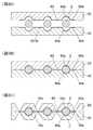
次に、図3を用いて実施例1の鉛筆の製造工程に関して説明を行う。図3は、図2と同じく鉛筆の横断面方向を示しており、図3Aでは、図2で示した軸部材4を形成する板材40には、複数の半円状の溝部40aを設けてあり、各溝部40aの両脇には、平面状の溝部40bを設けてある。また図2で示した軸部材5を形成する板材50には、複数の半円状の溝部50aを設けてあり、溝部50aの両脇には、平面状の溝部50bを設けてある。
また、板材40および板材50の各溝部には、導電性接着剤60を塗布してあり、溝部40aと溝部50aとの隙間に黒鉛と粘土を焼き固めた芯2を配設して板材40と板材50とを重ねることで、板材40と板材50との接着を行うと共に芯2の接着を行い一体としてある。こうすることで芯2と導電性接着剤60とが導通状態となる。尚、図3Bの状態から、図3Cに示すように、板材40と板材50の上下にV溝40c,50cを切削することにより、図2で示したような鉛筆1が形成される。Next, the manufacturing process of the pencil of Example 1 is demonstrated using FIG. 3 shows the cross-sectional direction of the pencil as in FIG. 2. In FIG. 3A, the
In addition, a
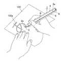
次に、図4を用いて、本実施例の鉛筆1で、紙面に筆記する状態について説明を行う。図に示すように鉛筆1は、芯2の先端部2aで紙100に文字100aを書くことができた。 Next, the state of writing on the paper surface with the
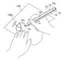
次に、図5を用いて、本実施例の鉛筆1で、静電容量方式の入力装置に入力する状態について説明を行う。図に示すように鉛筆1は、芯2の先端部2aを静電容量方式の入力装置110における操作領域110aに接触させて摺動させると、使用者が把持した軸体3の導電部6と芯2とを通じて操作領域110aに静電変化を生じさせ、画像作成ソフトウェアの画面に線110bを描くことができた。 Next, with reference to FIG. 5, a state in which the
(実施例2)
図6から図10を用いて実施例2の説明を行う。
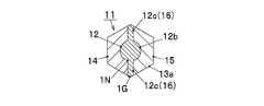
図6は実施例2の鉛筆の斜視図で、図7は図6のB−B線断面図である。
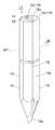
実施例2の鉛筆11は、黒鉛と粘土を焼き固めた芯12を、木材で成形した断面が六角形状の軸体13で保持する構造であり、軸体13の先端部を鉛筆削りで円錐状に削り、芯12の先端部12aを露出させてある。
軸体13を形成する二本の軸部材14,15の間には、芯12の本体部12bの側方へ延出する延出部12cを一体に形成し、導電部16としてある。
また、導電部16の外側縁部1Gは、軸体13の全長に渡って軸筒13の外面13aから露出させており、導電部16に軸体13を把持した使用者の手が触れるようにしてある。尚、芯12の本体部12bに対して導電部16(延出部12c)の内側縁部1Nを電気的に導通するように連設させてあることから、芯12の本体部12bと導電部16(延出部12c)の外側縁部1Gとは電気的に導通する。(Example 2)
The second embodiment will be described with reference to FIGS.
6 is a perspective view of the pencil of Example 2, and FIG. 7 is a cross-sectional view taken along the line BB of FIG.
The
Between the two
Further, the
次に、図8を用いて実施例2の鉛筆の製造工程に関して説明を行う。図8は、図7と同じく鉛筆の横断面方向を示しており、図8Aでは、図7で示した軸部材14を形成する板材140には、複数の半円状の溝部140aを設けてあり、各溝部140aの両脇には、平面状の溝部140bを設けてある。また図7で示した軸部材15を形成する板材150には、複数の半円状の溝部150aを設けてあり、溝部150aの両脇には、平面状の溝部150bを設けてある。
また、黒鉛と粘土を焼き固めた芯12は、本体部12bの両側から直線上(図7においては上下方向)に延出させた延出部12cを設けてあり、板材140,150の半円状の溝部140a,150aには芯12の本体部12bを、板材140,150の平面状の溝部140b,150bには芯12の延出部12cを配設すると共に、板材140,150における互いの接触面に接着剤(図示せず)を塗布して板材140と板材150とを重ねることで、板材140と板材150および芯12の接着を行い一体としてある。尚、図8Bの状態から、図8Cに示すように、板材140と板材150の上下にV溝140c,150cを切削することにより、図7で示したような鉛筆11が形成される。Next, the manufacturing process of the pencil of Example 2 will be described with reference to FIG. 8 shows the cross-sectional direction of the pencil as in FIG. 7. In FIG. 8A, the
Further, the core 12 obtained by baking and hardening graphite and clay is provided with an extending
次に、図9を用いて、本実施例の鉛筆11で、紙面に筆記する状態について説明を行う。図に示すように鉛筆11は、芯12の先端部12aで紙110に文字110aを書くことができた。 Next, with reference to FIG. 9, the state of writing on the paper surface with the
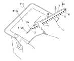
次に、図10を用いて、本実施例の鉛筆11で、静電容量方式の入力装置に入力する状態について説明を行う。図に示すように鉛筆11は、芯12の先端部12aを静電容量方式の入力装置110における操作領域110aに接触させて摺動させると、使用者が把持した軸体13の導電部16と芯12とを通じて操作領域110aに静電変化を生じさせ、画像作成ソフトウェアの画面に線110bを描くことができた。 Next, with reference to FIG. 10, a description will be given of a state in which the
(実施例3)
図11から図15を用いて実施例3の説明を行う。
図11は実施例3の鉛筆の斜視図で、図12は図11のC−C線断面図である。
実施例3の鉛筆21は、黒鉛と粘土を焼き固めた芯22を、木材で成形した断面が六角形状の軸体23で保持する構造であり、軸体23の先端部を鉛筆削りで円錐状に削り、芯22の先端部22aを露出させてある。
軸体23を形成する二本の軸部材24,25の間には、導電性を有するカーボンシート260からなる導電部26を設けてある。カーボンシート260は、芯22と軸部材24,25との間に接着剤を塗布して接着されており、カーボンシート260からなる導電部26は、芯22と軸部材24との間に位置する半円形部分26aと、軸部材24と軸部材25との間に位置する平面部分26bとを有している。
また、導電部26の平面部分26bの外側縁部2Gは、軸体23の全長に渡って軸筒23の外面23aから露出させており、導電部26に軸体23を把持した使用者の手が触れるようにしてある。尚、芯22に対して導電部26(平面部分26b)の内側縁部2Nを電気的に導通するように連結してあることから、芯22と導電部26の外側縁部2Gとは電気的に導通する。(Example 3)
The third embodiment will be described with reference to FIGS.
11 is a perspective view of the pencil of Example 3, and FIG. 12 is a cross-sectional view taken along the line CC of FIG.
The
Between the two
Further, the
次に、図13を用いて実施例3の鉛筆の製造工程に関して説明を行う。図13は、図12と同じく鉛筆の横断面方向を示しており、図13Aでは、図12で示した軸部材24を形成する板材240には、複数の半円状の溝部240aを設けてある。また図12で示した軸部材25を形成する板材250には、複数の半円状の溝部250aを設けてある。
溝部240aと溝部250aとの隙間に黒鉛と粘土を焼き固めた芯22を配設すると共に、板材250と芯22との間に可撓性を有したカーボンシート260を配し、板材240,250と芯22およびカーボンシート260における互いの接触面に接着剤(図示せず)を塗布して板材240と板材250とを重ねることで、板材240と板材250と芯22およびカーボンシート260の接着を行い一体としてある。
尚、図13Bの状態から、図13Cに示すように、板材240と板材250の上下にV溝240b,250bを切削することにより、図12で示したような鉛筆21が形成される。本実施例では、図13Cの状態で鉛筆21が正六角形になるように、カーボンシート260の厚さを考慮して、板材250の板厚T2を板材240の板厚T1より薄くし、板材250の半円状の溝部250aの半径R2を板材240の半円状の溝部240aの半径R1より大きく形成してある。Next, the manufacturing process of the pencil of Example 3 will be described with reference to FIG. FIG. 13 shows the cross-sectional direction of the pencil as in FIG. 12, and in FIG. 13A, the
A core 22 made of baked and hardened graphite and clay is disposed in a gap between the
13B, by cutting the
次に、図14を用いて、本実施例の鉛筆21で、紙面に筆記する状態について説明を行う。図に示すように鉛筆21は、芯22の先端部22aで紙110に文字110aを書くことができた。 Next, with reference to FIG. 14, the state of writing on the paper with the
次に、図15を用いて、本実施例の鉛筆21で、静電容量方式の入力装置に入力する状態について説明を行う。図に示すように鉛筆21は、芯22の先端部22aを静電容量方式の入力装置110における操作領域110aに接触させて摺動させると、使用者が把持した軸体23の導電部26と芯22とを通じて操作領域110aに静電変化を生じさせ、画像作成ソフトウェアの画面に線110bを描くことができた。 Next, with reference to FIG. 15, a state in which the
1,11,21…鉛筆、
2,12,22…芯、
2a,12a,22a…先端部、12b…本体部、12c…延出部、
3,13,23…軸体、3a,13a,23a…外面、
4,14,24…軸部材、5,15,25…軸部材、
40…板材、40a…半円状の溝部、40b…平面状の溝部、40c…V溝、
50…板材、50a…半円状の溝部、50b…平面状の溝部、50c…V溝、
140…板材、140a…半円状の溝部、140b…平面状の溝部、140c…V溝、
240…板材、240a…半円状の溝部、240b…V溝、
150…板材、150a…半円状の溝部、150b…平面状の溝部、150c…V溝、
250…板材、250a…半円状の溝部、250b…V溝、
6…導電部、6a…円形部分、6b…平面部分、60…導電性接着剤、
16…導電部、
26…導電部、26a…半円形部分、26b…平面部分、260…カーボンシート、
N,1N,2N…内側縁部、G,1G,2G…外側縁部、
100…紙、100a…文字、
110…入力装置、110a…操作領域、110b…線。1, 11, 21, ... pencil,
2, 12, 22 ... core
2a, 12a, 22a ... tip part, 12b ... main body part, 12c ... extension part,
3, 13, 23 ... shaft body, 3a, 13a, 23a ... outer surface,
4, 14, 24 ... shaft member, 5, 15, 25 ... shaft member,
40 ... Plate material, 40a ... Semicircular groove, 40b ... Planar groove, 40c ... V-groove,
50 ... Plate material, 50a ... Semicircular groove, 50b ... Planar groove, 50c ... V-groove,
140 ... plate material, 140a ... semicircular groove, 140b ... planar groove, 140c ... V groove,
240 ... plate material, 240a ... semicircular groove part, 240b ... V groove,
150 ... Plate material, 150a ... Semicircular groove, 150b ... Planar groove, 150c ... V groove,
250 ... plate material, 250a ... semicircular groove, 250b ... V groove,
6 ... conductive portion, 6a ... circular portion, 6b ... flat portion, 60 ... conductive adhesive,
16 ... conductive part,
26 ... conductive portion, 26a ... semicircular portion, 26b ... flat portion, 260 ... carbon sheet,
N, 1N, 2N ... inner edge, G, 1G, 2G ... outer edge,
100 ... paper, 100a ... characters,
110 ... input device, 110a ... operation area, 110b ... line.
Claims (3)
Translated fromJapanesePriority Applications (1)
| Application Number | Priority Date | Filing Date | Title |
|---|---|---|---|
| JP2013216702AJP6218552B2 (en) | 2013-10-17 | 2013-10-17 | pencil |
Applications Claiming Priority (1)
| Application Number | Priority Date | Filing Date | Title |
|---|---|---|---|
| JP2013216702AJP6218552B2 (en) | 2013-10-17 | 2013-10-17 | pencil |
Publications (2)
| Publication Number | Publication Date |
|---|---|
| JP2015077743A JP2015077743A (en) | 2015-04-23 |
| JP6218552B2true JP6218552B2 (en) | 2017-10-25 |
Family
ID=53009630
Family Applications (1)
| Application Number | Title | Priority Date | Filing Date |
|---|---|---|---|
| JP2013216702AActiveJP6218552B2 (en) | 2013-10-17 | 2013-10-17 | pencil |
Country Status (1)
| Country | Link |
|---|---|
| JP (1) | JP6218552B2 (en) |
Family Cites Families (9)
| Publication number | Priority date | Publication date | Assignee | Title |
|---|---|---|---|---|
| JPS4962068U (en)* | 1972-09-08 | 1974-05-31 | ||
| JP2587416Y2 (en)* | 1992-11-10 | 1998-12-16 | 株式会社トキワ | Lead brush |
| US7663607B2 (en)* | 2004-05-06 | 2010-02-16 | Apple Inc. | Multipoint touchscreen |
| JP4142776B2 (en)* | 1998-10-15 | 2008-09-03 | パイロットプレシジョン株式会社 | Input pen |
| JP3172736U (en)* | 2011-10-21 | 2012-01-05 | 株式会社いづみ企画 | Touch pen for capacitive panel |
| DE102012010965A1 (en)* | 2012-05-29 | 2013-12-05 | J. S. Staedtler Gmbh & Co. Kg | Input device for touch-sensitive, capacitive displays |
| JP6261900B2 (en)* | 2013-07-10 | 2018-01-17 | 株式会社パイロットコーポレーション | pencil |
| JP2015077745A (en)* | 2013-10-17 | 2015-04-23 | 株式会社パイロットコーポレーション | Pencil |
| JP2015077744A (en)* | 2013-10-17 | 2015-04-23 | 株式会社パイロットコーポレーション | Pencil |
- 2013
- 2013-10-17JPJP2013216702Apatent/JP6218552B2/enactiveActive
Also Published As
| Publication number | Publication date |
|---|---|
| JP2015077743A (en) | 2015-04-23 |
Similar Documents
| Publication | Publication Date | Title |
|---|---|---|
| CN201142063Y (en) | Capacitive touch control pen | |
| JP5854223B2 (en) | Input pen | |
| CN106406576A (en) | Method and kit for simultaneously forming entity handwriting and electronic handwriting and touch pen | |
| CN102736745A (en) | Capacitive touch control pen | |
| CN110858105A (en) | Capacitive touch control pen | |
| JP2013065147A (en) | Pen tip for touch pen, touch pen, touch pen with writing instrument, pen tip protrudable writing instrument and refill for input pen | |
| JP2015077745A (en) | Pencil | |
| JP2013137749A (en) | Input stylus pen | |
| CN210733639U (en) | Magnetic pen point assembly and writing board system using same | |
| JP2015077744A (en) | Pencil | |
| JP6218552B2 (en) | pencil | |
| CN101526860B (en) | capacitance pen | |
| JP2013080338A (en) | Stylus pen | |
| JP6261900B2 (en) | pencil | |
| JP5890693B2 (en) | Information input pen | |
| JP6173878B2 (en) | Pencil and pencil cap | |
| CN214704591U (en) | A Capacitive Touch Screen Supporting Writing | |
| JP2011257974A (en) | Pen and nib of capacitive touch panel | |
| CN202758324U (en) | Touch screen pen | |
| JP5990787B2 (en) | Stylus pen for capacitive touch panel | |
| CN206162427U (en) | Stylus disc stylus tip | |
| CN204833188U (en) | Touch -control pen | |
| JP2011242903A (en) | Capacitive pen | |
| JP3230189U (en) | Pencil cap | |
| CN202838221U (en) | The structure of the stylus |
Legal Events
| Date | Code | Title | Description |
|---|---|---|---|
| A621 | Written request for application examination | Free format text:JAPANESE INTERMEDIATE CODE: A621 Effective date:20160808 | |
| A977 | Report on retrieval | Free format text:JAPANESE INTERMEDIATE CODE: A971007 Effective date:20170725 | |
| A131 | Notification of reasons for refusal | Free format text:JAPANESE INTERMEDIATE CODE: A131 Effective date:20170808 | |
| A521 | Written amendment | Free format text:JAPANESE INTERMEDIATE CODE: A523 Effective date:20170906 | |
| TRDD | Decision of grant or rejection written | ||
| A01 | Written decision to grant a patent or to grant a registration (utility model) | Free format text:JAPANESE INTERMEDIATE CODE: A01 Effective date:20170926 | |
| A61 | First payment of annual fees (during grant procedure) | Free format text:JAPANESE INTERMEDIATE CODE: A61 Effective date:20170926 | |
| R150 | Certificate of patent or registration of utility model | Ref document number:6218552 Country of ref document:JP Free format text:JAPANESE INTERMEDIATE CODE: R150 |