JP6218149B2 - Input device assembly - Google Patents
Input device assemblyDownload PDFInfo
- Publication number
- JP6218149B2 JP6218149B2JP2014560118AJP2014560118AJP6218149B2JP 6218149 B2JP6218149 B2JP 6218149B2JP 2014560118 AJP2014560118 AJP 2014560118AJP 2014560118 AJP2014560118 AJP 2014560118AJP 6218149 B2JP6218149 B2JP 6218149B2
- Authority
- JP
- Japan
- Prior art keywords
- input device
- layer
- connection
- key assembly
- pressure sensitive
- Prior art date
- Legal status (The legal status is an assumption and is not a legal conclusion. Google has not performed a legal analysis and makes no representation as to the accuracy of the status listed.)
- Active
Links
Images


Classifications
- G—PHYSICS
- G06—COMPUTING OR CALCULATING; COUNTING
- G06F—ELECTRIC DIGITAL DATA PROCESSING
- G06F3/00—Input arrangements for transferring data to be processed into a form capable of being handled by the computer; Output arrangements for transferring data from processing unit to output unit, e.g. interface arrangements
- G06F3/01—Input arrangements or combined input and output arrangements for interaction between user and computer
- G06F3/03—Arrangements for converting the position or the displacement of a member into a coded form
- G06F3/041—Digitisers, e.g. for touch screens or touch pads, characterised by the transducing means
- G06F3/0414—Digitisers, e.g. for touch screens or touch pads, characterised by the transducing means using force sensing means to determine a position
- E—FIXED CONSTRUCTIONS
- E05—LOCKS; KEYS; WINDOW OR DOOR FITTINGS; SAFES
- E05D—HINGES OR SUSPENSION DEVICES FOR DOORS, WINDOWS OR WINGS
- E05D11/00—Additional features or accessories of hinges
- E05D11/10—Devices for preventing movement between relatively-movable hinge parts
- E05D11/1028—Devices for preventing movement between relatively-movable hinge parts for maintaining the hinge in two or more positions, e.g. intermediate or fully open
- E05D11/105—Devices for preventing movement between relatively-movable hinge parts for maintaining the hinge in two or more positions, e.g. intermediate or fully open the maintaining means acting perpendicularly to the pivot axis
- E05D11/1064—Devices for preventing movement between relatively-movable hinge parts for maintaining the hinge in two or more positions, e.g. intermediate or fully open the maintaining means acting perpendicularly to the pivot axis with a coil spring perpendicular to the pivot axis
- E—FIXED CONSTRUCTIONS
- E05—LOCKS; KEYS; WINDOW OR DOOR FITTINGS; SAFES
- E05F—DEVICES FOR MOVING WINGS INTO OPEN OR CLOSED POSITION; CHECKS FOR WINGS; WING FITTINGS NOT OTHERWISE PROVIDED FOR, CONCERNED WITH THE FUNCTIONING OF THE WING
- E05F5/00—Braking devices, e.g. checks; Stops; Buffers
- E05F5/06—Buffers or stops limiting opening of swinging wings, e.g. floor or wall stops
- E05F5/08—Buffers or stops limiting opening of swinging wings, e.g. floor or wall stops with springs
- F—MECHANICAL ENGINEERING; LIGHTING; HEATING; WEAPONS; BLASTING
- F16—ENGINEERING ELEMENTS AND UNITS; GENERAL MEASURES FOR PRODUCING AND MAINTAINING EFFECTIVE FUNCTIONING OF MACHINES OR INSTALLATIONS; THERMAL INSULATION IN GENERAL
- F16M—FRAMES, CASINGS OR BEDS OF ENGINES, MACHINES OR APPARATUS, NOT SPECIFIC TO ENGINES, MACHINES OR APPARATUS PROVIDED FOR ELSEWHERE; STANDS; SUPPORTS
- F16M11/00—Stands or trestles as supports for apparatus or articles placed thereon ; Stands for scientific apparatus such as gravitational force meters
- F16M11/20—Undercarriages with or without wheels
- F16M11/24—Undercarriages with or without wheels changeable in height or length of legs, also for transport only, e.g. by means of tubes screwed into each other
- F16M11/38—Undercarriages with or without wheels changeable in height or length of legs, also for transport only, e.g. by means of tubes screwed into each other by folding, e.g. pivoting or scissors tong mechanisms
- G—PHYSICS
- G05—CONTROLLING; REGULATING
- G05B—CONTROL OR REGULATING SYSTEMS IN GENERAL; FUNCTIONAL ELEMENTS OF SUCH SYSTEMS; MONITORING OR TESTING ARRANGEMENTS FOR SUCH SYSTEMS OR ELEMENTS
- G05B11/00—Automatic controllers
- G05B11/01—Automatic controllers electric
- G—PHYSICS
- G06—COMPUTING OR CALCULATING; COUNTING
- G06F—ELECTRIC DIGITAL DATA PROCESSING
- G06F1/00—Details not covered by groups G06F3/00 - G06F13/00 and G06F21/00
- G06F1/16—Constructional details or arrangements
- G06F1/1613—Constructional details or arrangements for portable computers
- G06F1/1615—Constructional details or arrangements for portable computers with several enclosures having relative motions, each enclosure supporting at least one I/O or computing function
- G06F1/1616—Constructional details or arrangements for portable computers with several enclosures having relative motions, each enclosure supporting at least one I/O or computing function with folding flat displays, e.g. laptop computers or notebooks having a clamshell configuration, with body parts pivoting to an open position around an axis parallel to the plane they define in closed position
- G06F1/1618—Constructional details or arrangements for portable computers with several enclosures having relative motions, each enclosure supporting at least one I/O or computing function with folding flat displays, e.g. laptop computers or notebooks having a clamshell configuration, with body parts pivoting to an open position around an axis parallel to the plane they define in closed position the display being foldable up to the back of the other housing with a single degree of freedom, e.g. by 360° rotation over the axis defined by the rear edge of the base enclosure
- G—PHYSICS
- G06—COMPUTING OR CALCULATING; COUNTING
- G06F—ELECTRIC DIGITAL DATA PROCESSING
- G06F1/00—Details not covered by groups G06F3/00 - G06F13/00 and G06F21/00
- G06F1/16—Constructional details or arrangements
- G06F1/1613—Constructional details or arrangements for portable computers
- G06F1/1633—Constructional details or arrangements of portable computers not specific to the type of enclosures covered by groups G06F1/1615 - G06F1/1626
- G06F1/1637—Details related to the display arrangement, including those related to the mounting of the display in the housing
- G06F1/1654—Details related to the display arrangement, including those related to the mounting of the display in the housing the display being detachable, e.g. for remote use
- G—PHYSICS
- G06—COMPUTING OR CALCULATING; COUNTING
- G06F—ELECTRIC DIGITAL DATA PROCESSING
- G06F1/00—Details not covered by groups G06F3/00 - G06F13/00 and G06F21/00
- G06F1/16—Constructional details or arrangements
- G06F1/1613—Constructional details or arrangements for portable computers
- G06F1/1633—Constructional details or arrangements of portable computers not specific to the type of enclosures covered by groups G06F1/1615 - G06F1/1626
- G06F1/1656—Details related to functional adaptations of the enclosure, e.g. to provide protection against EMI, shock, water, or to host detachable peripherals like a mouse or removable expansions units like PCMCIA cards, or to provide access to internal components for maintenance or to removable storage supports like CDs or DVDs, or to mechanically mount accessories
- G06F1/166—Details related to functional adaptations of the enclosure, e.g. to provide protection against EMI, shock, water, or to host detachable peripherals like a mouse or removable expansions units like PCMCIA cards, or to provide access to internal components for maintenance or to removable storage supports like CDs or DVDs, or to mechanically mount accessories related to integrated arrangements for adjusting the position of the main body with respect to the supporting surface, e.g. legs for adjusting the tilt angle
- G—PHYSICS
- G06—COMPUTING OR CALCULATING; COUNTING
- G06F—ELECTRIC DIGITAL DATA PROCESSING
- G06F1/00—Details not covered by groups G06F3/00 - G06F13/00 and G06F21/00
- G06F1/16—Constructional details or arrangements
- G06F1/1613—Constructional details or arrangements for portable computers
- G06F1/1633—Constructional details or arrangements of portable computers not specific to the type of enclosures covered by groups G06F1/1615 - G06F1/1626
- G06F1/1662—Details related to the integrated keyboard
- G06F1/1669—Detachable keyboards
- G—PHYSICS
- G06—COMPUTING OR CALCULATING; COUNTING
- G06F—ELECTRIC DIGITAL DATA PROCESSING
- G06F1/00—Details not covered by groups G06F3/00 - G06F13/00 and G06F21/00
- G06F1/16—Constructional details or arrangements
- G06F1/1613—Constructional details or arrangements for portable computers
- G06F1/1633—Constructional details or arrangements of portable computers not specific to the type of enclosures covered by groups G06F1/1615 - G06F1/1626
- G06F1/1675—Miscellaneous details related to the relative movement between the different enclosures or enclosure parts
- G06F1/1681—Details related solely to hinges
- G—PHYSICS
- G06—COMPUTING OR CALCULATING; COUNTING
- G06F—ELECTRIC DIGITAL DATA PROCESSING
- G06F1/00—Details not covered by groups G06F3/00 - G06F13/00 and G06F21/00
- G06F1/16—Constructional details or arrangements
- G06F1/1613—Constructional details or arrangements for portable computers
- G06F1/1633—Constructional details or arrangements of portable computers not specific to the type of enclosures covered by groups G06F1/1615 - G06F1/1626
- G06F1/1675—Miscellaneous details related to the relative movement between the different enclosures or enclosure parts
- G06F1/1683—Miscellaneous details related to the relative movement between the different enclosures or enclosure parts for the transmission of signal or power between the different housings, e.g. details of wired or wireless communication, passage of cabling
- G—PHYSICS
- G06—COMPUTING OR CALCULATING; COUNTING
- G06F—ELECTRIC DIGITAL DATA PROCESSING
- G06F1/00—Details not covered by groups G06F3/00 - G06F13/00 and G06F21/00
- G06F1/16—Constructional details or arrangements
- G06F1/1613—Constructional details or arrangements for portable computers
- G06F1/1633—Constructional details or arrangements of portable computers not specific to the type of enclosures covered by groups G06F1/1615 - G06F1/1626
- G06F1/1684—Constructional details or arrangements related to integrated I/O peripherals not covered by groups G06F1/1635 - G06F1/1675
- G06F1/1686—Constructional details or arrangements related to integrated I/O peripherals not covered by groups G06F1/1635 - G06F1/1675 the I/O peripheral being an integrated camera
- G—PHYSICS
- G06—COMPUTING OR CALCULATING; COUNTING
- G06F—ELECTRIC DIGITAL DATA PROCESSING
- G06F11/00—Error detection; Error correction; Monitoring
- G06F11/30—Monitoring
- G06F11/3089—Monitoring arrangements determined by the means or processing involved in sensing the monitored data, e.g. interfaces, connectors, sensors, probes, agents
- G—PHYSICS
- G06—COMPUTING OR CALCULATING; COUNTING
- G06F—ELECTRIC DIGITAL DATA PROCESSING
- G06F13/00—Interconnection of, or transfer of information or other signals between, memories, input/output devices or central processing units
- G06F13/10—Program control for peripheral devices
- G06F13/102—Program control for peripheral devices where the programme performs an interfacing function, e.g. device driver
- G—PHYSICS
- G06—COMPUTING OR CALCULATING; COUNTING
- G06F—ELECTRIC DIGITAL DATA PROCESSING
- G06F3/00—Input arrangements for transferring data to be processed into a form capable of being handled by the computer; Output arrangements for transferring data from processing unit to output unit, e.g. interface arrangements
- G06F3/002—Specific input/output arrangements not covered by G06F3/01 - G06F3/16
- G—PHYSICS
- G06—COMPUTING OR CALCULATING; COUNTING
- G06F—ELECTRIC DIGITAL DATA PROCESSING
- G06F3/00—Input arrangements for transferring data to be processed into a form capable of being handled by the computer; Output arrangements for transferring data from processing unit to output unit, e.g. interface arrangements
- G06F3/01—Input arrangements or combined input and output arrangements for interaction between user and computer
- G06F3/02—Input arrangements using manually operated switches, e.g. using keyboards or dials
- G06F3/0202—Constructional details or processes of manufacture of the input device
- G06F3/0219—Special purpose keyboards
- G—PHYSICS
- G06—COMPUTING OR CALCULATING; COUNTING
- G06F—ELECTRIC DIGITAL DATA PROCESSING
- G06F3/00—Input arrangements for transferring data to be processed into a form capable of being handled by the computer; Output arrangements for transferring data from processing unit to output unit, e.g. interface arrangements
- G06F3/01—Input arrangements or combined input and output arrangements for interaction between user and computer
- G06F3/02—Input arrangements using manually operated switches, e.g. using keyboards or dials
- G06F3/023—Arrangements for converting discrete items of information into a coded form, e.g. arrangements for interpreting keyboard generated codes as alphanumeric codes, operand codes or instruction codes
- G06F3/0233—Character input methods
- G—PHYSICS
- G06—COMPUTING OR CALCULATING; COUNTING
- G06F—ELECTRIC DIGITAL DATA PROCESSING
- G06F3/00—Input arrangements for transferring data to be processed into a form capable of being handled by the computer; Output arrangements for transferring data from processing unit to output unit, e.g. interface arrangements
- G06F3/01—Input arrangements or combined input and output arrangements for interaction between user and computer
- G06F3/03—Arrangements for converting the position or the displacement of a member into a coded form
- G06F3/041—Digitisers, e.g. for touch screens or touch pads, characterised by the transducing means
- G06F3/0416—Control or interface arrangements specially adapted for digitisers
- G—PHYSICS
- G06—COMPUTING OR CALCULATING; COUNTING
- G06F—ELECTRIC DIGITAL DATA PROCESSING
- G06F3/00—Input arrangements for transferring data to be processed into a form capable of being handled by the computer; Output arrangements for transferring data from processing unit to output unit, e.g. interface arrangements
- G06F3/01—Input arrangements or combined input and output arrangements for interaction between user and computer
- G06F3/048—Interaction techniques based on graphical user interfaces [GUI]
- G06F3/0487—Interaction techniques based on graphical user interfaces [GUI] using specific features provided by the input device, e.g. functions controlled by the rotation of a mouse with dual sensing arrangements, or of the nature of the input device, e.g. tap gestures based on pressure sensed by a digitiser
- G06F3/0488—Interaction techniques based on graphical user interfaces [GUI] using specific features provided by the input device, e.g. functions controlled by the rotation of a mouse with dual sensing arrangements, or of the nature of the input device, e.g. tap gestures based on pressure sensed by a digitiser using a touch-screen or digitiser, e.g. input of commands through traced gestures
- G06F3/04886—Interaction techniques based on graphical user interfaces [GUI] using specific features provided by the input device, e.g. functions controlled by the rotation of a mouse with dual sensing arrangements, or of the nature of the input device, e.g. tap gestures based on pressure sensed by a digitiser using a touch-screen or digitiser, e.g. input of commands through traced gestures by partitioning the display area of the touch-screen or the surface of the digitising tablet into independently controllable areas, e.g. virtual keyboards or menus
- G—PHYSICS
- G06—COMPUTING OR CALCULATING; COUNTING
- G06F—ELECTRIC DIGITAL DATA PROCESSING
- G06F9/00—Arrangements for program control, e.g. control units
- G06F9/06—Arrangements for program control, e.g. control units using stored programs, i.e. using an internal store of processing equipment to receive or retain programs
- G06F9/46—Multiprogramming arrangements
- G06F9/54—Interprogram communication
- G06F9/541—Interprogram communication via adapters, e.g. between incompatible applications
- H—ELECTRICITY
- H01—ELECTRIC ELEMENTS
- H01H—ELECTRIC SWITCHES; RELAYS; SELECTORS; EMERGENCY PROTECTIVE DEVICES
- H01H11/00—Apparatus or processes specially adapted for the manufacture of electric switches
- H—ELECTRICITY
- H01—ELECTRIC ELEMENTS
- H01H—ELECTRIC SWITCHES; RELAYS; SELECTORS; EMERGENCY PROTECTIVE DEVICES
- H01H13/00—Switches having rectilinearly-movable operating part or parts adapted for pushing or pulling in one direction only, e.g. push-button switch
- H01H13/02—Details
- H01H13/12—Movable parts; Contacts mounted thereon
- H01H13/14—Operating parts, e.g. push-button
- H—ELECTRICITY
- H01—ELECTRIC ELEMENTS
- H01H—ELECTRIC SWITCHES; RELAYS; SELECTORS; EMERGENCY PROTECTIVE DEVICES
- H01H13/00—Switches having rectilinearly-movable operating part or parts adapted for pushing or pulling in one direction only, e.g. push-button switch
- H01H13/70—Switches having rectilinearly-movable operating part or parts adapted for pushing or pulling in one direction only, e.g. push-button switch having a plurality of operating members associated with different sets of contacts, e.g. keyboard
- H01H13/702—Switches having rectilinearly-movable operating part or parts adapted for pushing or pulling in one direction only, e.g. push-button switch having a plurality of operating members associated with different sets of contacts, e.g. keyboard with contacts carried by or formed from layers in a multilayer structure, e.g. membrane switches
- H01H13/703—Switches having rectilinearly-movable operating part or parts adapted for pushing or pulling in one direction only, e.g. push-button switch having a plurality of operating members associated with different sets of contacts, e.g. keyboard with contacts carried by or formed from layers in a multilayer structure, e.g. membrane switches characterised by spacers between contact carrying layers
- H—ELECTRICITY
- H01—ELECTRIC ELEMENTS
- H01H—ELECTRIC SWITCHES; RELAYS; SELECTORS; EMERGENCY PROTECTIVE DEVICES
- H01H13/00—Switches having rectilinearly-movable operating part or parts adapted for pushing or pulling in one direction only, e.g. push-button switch
- H01H13/70—Switches having rectilinearly-movable operating part or parts adapted for pushing or pulling in one direction only, e.g. push-button switch having a plurality of operating members associated with different sets of contacts, e.g. keyboard
- H01H13/702—Switches having rectilinearly-movable operating part or parts adapted for pushing or pulling in one direction only, e.g. push-button switch having a plurality of operating members associated with different sets of contacts, e.g. keyboard with contacts carried by or formed from layers in a multilayer structure, e.g. membrane switches
- H01H13/704—Switches having rectilinearly-movable operating part or parts adapted for pushing or pulling in one direction only, e.g. push-button switch having a plurality of operating members associated with different sets of contacts, e.g. keyboard with contacts carried by or formed from layers in a multilayer structure, e.g. membrane switches characterised by the layers, e.g. by their material or structure
- H—ELECTRICITY
- H01—ELECTRIC ELEMENTS
- H01H—ELECTRIC SWITCHES; RELAYS; SELECTORS; EMERGENCY PROTECTIVE DEVICES
- H01H13/00—Switches having rectilinearly-movable operating part or parts adapted for pushing or pulling in one direction only, e.g. push-button switch
- H01H13/70—Switches having rectilinearly-movable operating part or parts adapted for pushing or pulling in one direction only, e.g. push-button switch having a plurality of operating members associated with different sets of contacts, e.g. keyboard
- H01H13/78—Switches having rectilinearly-movable operating part or parts adapted for pushing or pulling in one direction only, e.g. push-button switch having a plurality of operating members associated with different sets of contacts, e.g. keyboard characterised by the contacts or the contact sites
- H01H13/785—Switches having rectilinearly-movable operating part or parts adapted for pushing or pulling in one direction only, e.g. push-button switch having a plurality of operating members associated with different sets of contacts, e.g. keyboard characterised by the contacts or the contact sites characterised by the material of the contacts, e.g. conductive polymers
- H—ELECTRICITY
- H01—ELECTRIC ELEMENTS
- H01H—ELECTRIC SWITCHES; RELAYS; SELECTORS; EMERGENCY PROTECTIVE DEVICES
- H01H13/00—Switches having rectilinearly-movable operating part or parts adapted for pushing or pulling in one direction only, e.g. push-button switch
- H01H13/70—Switches having rectilinearly-movable operating part or parts adapted for pushing or pulling in one direction only, e.g. push-button switch having a plurality of operating members associated with different sets of contacts, e.g. keyboard
- H01H13/78—Switches having rectilinearly-movable operating part or parts adapted for pushing or pulling in one direction only, e.g. push-button switch having a plurality of operating members associated with different sets of contacts, e.g. keyboard characterised by the contacts or the contact sites
- H01H13/79—Switches having rectilinearly-movable operating part or parts adapted for pushing or pulling in one direction only, e.g. push-button switch having a plurality of operating members associated with different sets of contacts, e.g. keyboard characterised by the contacts or the contact sites characterised by the form of the contacts, e.g. interspersed fingers or helical networks
- H—ELECTRICITY
- H01—ELECTRIC ELEMENTS
- H01H—ELECTRIC SWITCHES; RELAYS; SELECTORS; EMERGENCY PROTECTIVE DEVICES
- H01H13/00—Switches having rectilinearly-movable operating part or parts adapted for pushing or pulling in one direction only, e.g. push-button switch
- H01H13/70—Switches having rectilinearly-movable operating part or parts adapted for pushing or pulling in one direction only, e.g. push-button switch having a plurality of operating members associated with different sets of contacts, e.g. keyboard
- H01H13/78—Switches having rectilinearly-movable operating part or parts adapted for pushing or pulling in one direction only, e.g. push-button switch having a plurality of operating members associated with different sets of contacts, e.g. keyboard characterised by the contacts or the contact sites
- H01H13/807—Switches having rectilinearly-movable operating part or parts adapted for pushing or pulling in one direction only, e.g. push-button switch having a plurality of operating members associated with different sets of contacts, e.g. keyboard characterised by the contacts or the contact sites characterised by the spatial arrangement of the contact sites, e.g. superimposed sites
- H—ELECTRICITY
- H01—ELECTRIC ELEMENTS
- H01H—ELECTRIC SWITCHES; RELAYS; SELECTORS; EMERGENCY PROTECTIVE DEVICES
- H01H13/00—Switches having rectilinearly-movable operating part or parts adapted for pushing or pulling in one direction only, e.g. push-button switch
- H01H13/70—Switches having rectilinearly-movable operating part or parts adapted for pushing or pulling in one direction only, e.g. push-button switch having a plurality of operating members associated with different sets of contacts, e.g. keyboard
- H01H13/82—Switches having rectilinearly-movable operating part or parts adapted for pushing or pulling in one direction only, e.g. push-button switch having a plurality of operating members associated with different sets of contacts, e.g. keyboard characterised by contact space venting means
- H—ELECTRICITY
- H04—ELECTRIC COMMUNICATION TECHNIQUE
- H04M—TELEPHONIC COMMUNICATION
- H04M1/00—Substation equipment, e.g. for use by subscribers
- H04M1/02—Constructional features of telephone sets
- H04M1/0202—Portable telephone sets, e.g. cordless phones, mobile phones or bar type handsets
- H04M1/0206—Portable telephones comprising a plurality of mechanically joined movable body parts, e.g. hinged housings
- H04M1/0208—Portable telephones comprising a plurality of mechanically joined movable body parts, e.g. hinged housings characterized by the relative motions of the body parts
- H04M1/0214—Foldable telephones, i.e. with body parts pivoting to an open position around an axis parallel to the plane they define in closed position
- H04M1/0216—Foldable in one direction, i.e. using a one degree of freedom hinge
- H—ELECTRICITY
- H04—ELECTRIC COMMUNICATION TECHNIQUE
- H04M—TELEPHONIC COMMUNICATION
- H04M1/00—Substation equipment, e.g. for use by subscribers
- H04M1/02—Constructional features of telephone sets
- H04M1/0202—Portable telephone sets, e.g. cordless phones, mobile phones or bar type handsets
- H04M1/0254—Portable telephone sets, e.g. cordless phones, mobile phones or bar type handsets comprising one or a plurality of mechanically detachable modules
- H—ELECTRICITY
- H04—ELECTRIC COMMUNICATION TECHNIQUE
- H04M—TELEPHONIC COMMUNICATION
- H04M1/00—Substation equipment, e.g. for use by subscribers
- H04M1/72—Mobile telephones; Cordless telephones, i.e. devices for establishing wireless links to base stations without route selection
- H04M1/724—User interfaces specially adapted for cordless or mobile telephones
- H04M1/72403—User interfaces specially adapted for cordless or mobile telephones with means for local support of applications that increase the functionality
- H04M1/72409—User interfaces specially adapted for cordless or mobile telephones with means for local support of applications that increase the functionality by interfacing with external accessories
- H—ELECTRICITY
- H05—ELECTRIC TECHNIQUES NOT OTHERWISE PROVIDED FOR
- H05K—PRINTED CIRCUITS; CASINGS OR CONSTRUCTIONAL DETAILS OF ELECTRIC APPARATUS; MANUFACTURE OF ASSEMBLAGES OF ELECTRICAL COMPONENTS
- H05K5/00—Casings, cabinets or drawers for electric apparatus
- H05K5/02—Details
- H05K5/0217—Mechanical details of casings
- H05K5/0226—Hinges
- H—ELECTRICITY
- H05—ELECTRIC TECHNIQUES NOT OTHERWISE PROVIDED FOR
- H05K—PRINTED CIRCUITS; CASINGS OR CONSTRUCTIONAL DETAILS OF ELECTRIC APPARATUS; MANUFACTURE OF ASSEMBLAGES OF ELECTRICAL COMPONENTS
- H05K5/00—Casings, cabinets or drawers for electric apparatus
- H05K5/02—Details
- H05K5/0217—Mechanical details of casings
- H05K5/0234—Feet; Stands; Pedestals, e.g. wheels for moving casing on floor
- E—FIXED CONSTRUCTIONS
- E05—LOCKS; KEYS; WINDOW OR DOOR FITTINGS; SAFES
- E05Y—INDEXING SCHEME ASSOCIATED WITH SUBCLASSES E05D AND E05F, RELATING TO CONSTRUCTION ELEMENTS, ELECTRIC CONTROL, POWER SUPPLY, POWER SIGNAL OR TRANSMISSION, USER INTERFACES, MOUNTING OR COUPLING, DETAILS, ACCESSORIES, AUXILIARY OPERATIONS NOT OTHERWISE PROVIDED FOR, APPLICATION THEREOF
- E05Y2201/00—Constructional elements; Accessories therefor
- E05Y2201/40—Motors; Magnets; Springs; Weights; Accessories therefor
- E05Y2201/46—Magnets
- H—ELECTRICITY
- H01—ELECTRIC ELEMENTS
- H01H—ELECTRIC SWITCHES; RELAYS; SELECTORS; EMERGENCY PROTECTIVE DEVICES
- H01H2201/00—Contacts
- H01H2201/022—Material
- H01H2201/032—Conductive polymer; Rubber
- H01H2201/036—Variable resistance
- H—ELECTRICITY
- H01—ELECTRIC ELEMENTS
- H01H—ELECTRIC SWITCHES; RELAYS; SELECTORS; EMERGENCY PROTECTIVE DEVICES
- H01H2203/00—Form of contacts
- H01H2203/02—Interspersed fingers
- H—ELECTRICITY
- H01—ELECTRIC ELEMENTS
- H01H—ELECTRIC SWITCHES; RELAYS; SELECTORS; EMERGENCY PROTECTIVE DEVICES
- H01H2203/00—Form of contacts
- H01H2203/036—Form of contacts to solve particular problems
- H—ELECTRICITY
- H01—ELECTRIC ELEMENTS
- H01H—ELECTRIC SWITCHES; RELAYS; SELECTORS; EMERGENCY PROTECTIVE DEVICES
- H01H2203/00—Form of contacts
- H01H2203/058—Contact area function of position on layered keyboard
- H—ELECTRICITY
- H01—ELECTRIC ELEMENTS
- H01H—ELECTRIC SWITCHES; RELAYS; SELECTORS; EMERGENCY PROTECTIVE DEVICES
- H01H2205/00—Movable contacts
- H01H2205/006—Movable contacts mounted on spacer
- H—ELECTRICITY
- H01—ELECTRIC ELEMENTS
- H01H—ELECTRIC SWITCHES; RELAYS; SELECTORS; EMERGENCY PROTECTIVE DEVICES
- H01H2211/00—Spacers
- H01H2211/004—Adhesive
- H—ELECTRICITY
- H01—ELECTRIC ELEMENTS
- H01H—ELECTRIC SWITCHES; RELAYS; SELECTORS; EMERGENCY PROTECTIVE DEVICES
- H01H2211/00—Spacers
- H01H2211/006—Individual areas
- H—ELECTRICITY
- H01—ELECTRIC ELEMENTS
- H01H—ELECTRIC SWITCHES; RELAYS; SELECTORS; EMERGENCY PROTECTIVE DEVICES
- H01H2213/00—Venting
- H01H2213/016—Venting in adhesive layer
- H—ELECTRICITY
- H01—ELECTRIC ELEMENTS
- H01H—ELECTRIC SWITCHES; RELAYS; SELECTORS; EMERGENCY PROTECTIVE DEVICES
- H01H2217/00—Facilitation of operation; Human engineering
- H01H2217/004—Larger or different actuating area
- H—ELECTRICITY
- H01—ELECTRIC ELEMENTS
- H01H—ELECTRIC SWITCHES; RELAYS; SELECTORS; EMERGENCY PROTECTIVE DEVICES
- H01H2217/00—Facilitation of operation; Human engineering
- H01H2217/006—Different feeling for different switch sites
- H—ELECTRICITY
- H01—ELECTRIC ELEMENTS
- H01H—ELECTRIC SWITCHES; RELAYS; SELECTORS; EMERGENCY PROTECTIVE DEVICES
- H01H2217/00—Facilitation of operation; Human engineering
- H01H2217/01—Off centre actuation
- H—ELECTRICITY
- H01—ELECTRIC ELEMENTS
- H01H—ELECTRIC SWITCHES; RELAYS; SELECTORS; EMERGENCY PROTECTIVE DEVICES
- H01H2227/00—Dimensions; Characteristics
- H01H2227/032—Operating force
- H—ELECTRICITY
- H01—ELECTRIC ELEMENTS
- H01H—ELECTRIC SWITCHES; RELAYS; SELECTORS; EMERGENCY PROTECTIVE DEVICES
- H01H9/00—Details of switching devices, not covered by groups H01H1/00 - H01H7/00
- H01H9/20—Interlocking, locking, or latching mechanisms
- H01H9/26—Interlocking, locking, or latching mechanisms for interlocking two or more switches
- H—ELECTRICITY
- H04—ELECTRIC COMMUNICATION TECHNIQUE
- H04M—TELEPHONIC COMMUNICATION
- H04M1/00—Substation equipment, e.g. for use by subscribers
- H04M1/02—Constructional features of telephone sets
- H04M1/0202—Portable telephone sets, e.g. cordless phones, mobile phones or bar type handsets
- H04M1/0206—Portable telephones comprising a plurality of mechanically joined movable body parts, e.g. hinged housings
- H04M1/0241—Portable telephones comprising a plurality of mechanically joined movable body parts, e.g. hinged housings using relative motion of the body parts to change the operational status of the telephone set, e.g. switching on/off, answering incoming call
- H04M1/0245—Portable telephones comprising a plurality of mechanically joined movable body parts, e.g. hinged housings using relative motion of the body parts to change the operational status of the telephone set, e.g. switching on/off, answering incoming call using open/close detection
- Y—GENERAL TAGGING OF NEW TECHNOLOGICAL DEVELOPMENTS; GENERAL TAGGING OF CROSS-SECTIONAL TECHNOLOGIES SPANNING OVER SEVERAL SECTIONS OF THE IPC; TECHNICAL SUBJECTS COVERED BY FORMER USPC CROSS-REFERENCE ART COLLECTIONS [XRACs] AND DIGESTS
- Y02—TECHNOLOGIES OR APPLICATIONS FOR MITIGATION OR ADAPTATION AGAINST CLIMATE CHANGE
- Y02D—CLIMATE CHANGE MITIGATION TECHNOLOGIES IN INFORMATION AND COMMUNICATION TECHNOLOGIES [ICT], I.E. INFORMATION AND COMMUNICATION TECHNOLOGIES AIMING AT THE REDUCTION OF THEIR OWN ENERGY USE
- Y02D10/00—Energy efficient computing, e.g. low power processors, power management or thermal management
- Y—GENERAL TAGGING OF NEW TECHNOLOGICAL DEVELOPMENTS; GENERAL TAGGING OF CROSS-SECTIONAL TECHNOLOGIES SPANNING OVER SEVERAL SECTIONS OF THE IPC; TECHNICAL SUBJECTS COVERED BY FORMER USPC CROSS-REFERENCE ART COLLECTIONS [XRACs] AND DIGESTS
- Y10—TECHNICAL SUBJECTS COVERED BY FORMER USPC
- Y10T—TECHNICAL SUBJECTS COVERED BY FORMER US CLASSIFICATION
- Y10T29/00—Metal working
- Y10T29/49—Method of mechanical manufacture
- Y10T29/49826—Assembling or joining
Landscapes
- Engineering & Computer Science (AREA)
- Theoretical Computer Science (AREA)
- General Engineering & Computer Science (AREA)
- Physics & Mathematics (AREA)
- General Physics & Mathematics (AREA)
- Human Computer Interaction (AREA)
- Computer Hardware Design (AREA)
- Signal Processing (AREA)
- Mathematical Physics (AREA)
- Computer Networks & Wireless Communication (AREA)
- Microelectronics & Electronic Packaging (AREA)
- Software Systems (AREA)
- Mechanical Engineering (AREA)
- Automation & Control Theory (AREA)
- Quality & Reliability (AREA)
- Manufacturing & Machinery (AREA)
- Input From Keyboards Or The Like (AREA)
- Telephone Set Structure (AREA)
- User Interface Of Digital Computer (AREA)
- Push-Button Switches (AREA)
- Casings For Electric Apparatus (AREA)
- Studio Devices (AREA)
- Position Input By Displaying (AREA)
- Information Retrieval, Db Structures And Fs Structures Therefor (AREA)
- Coupling Device And Connection With Printed Circuit (AREA)
- Manipulator (AREA)
- Gyroscopes (AREA)
- Details Of Measuring And Other Instruments (AREA)
- Pivots And Pivotal Connections (AREA)
- Length Measuring Devices With Unspecified Measuring Means (AREA)
- Force Measurement Appropriate To Specific Purposes (AREA)
- Telephone Function (AREA)
- Control Of Indicators Other Than Cathode Ray Tubes (AREA)
- Details Of Cameras Including Film Mechanisms (AREA)
- Toys (AREA)
Description
Translated fromJapanese本発明は、入力装置アセンブリに関する。 The present invention relates to an input device assembly.
モバイルコンピュータ装置は、ユーザがモバイル環境で利用可能な機能性を高めるために開発されてきた。例えば、ユーザは、eメールを確認する、ネットサーフィンを行う、文章を構成する、アプリケーションと対話する等を行うために、携帯電話や、タブレット型コンピュータ、又は他のモバイルコンピュータ装置と情報をやり取りしている。しかしながら、タッチスクリーン機能を使用してアクセスするような従来のモバイルコンピュータ装置は、大抵の場合、仮想キーボードを用いていた。これは、一般的に、コンピュータ装置の表示領域の大きさを最大化するために用いられていた。 Mobile computing devices have been developed to increase the functionality available to users in a mobile environment. For example, a user interacts with a mobile phone, tablet computer, or other mobile computer device to check email, surf the web, compose text, interact with applications, etc. ing. However, conventional mobile computing devices, such as those accessed using touch screen functions, often used virtual keyboards. This has generally been used to maximize the size of the display area of a computer device.
しかしながら、仮想キーボードの使用は、相当な量のテキストを入力して長い電子メール、文書等を構成する等の、相当な量を入力するのを所望するユーザにとって苛立たしいものであった。こうして、従来のモバイルコンピュータ装置は、大抵の場合、具体的にはユーザが例えば従来のデスクトップ型コンピュータの従来のキーボードを使用してテキストを容易に入力することと比較して、このようなタスクについて有用性を制限するものだと考えられていた。モバイルコンピュータ装置と一緒に従来のキーボードを使用する場合であっても、モバイルコンピュータ装置の移動度を低下させ、こうしてモバイルコンピュータ装置はモバイル環境での上述した相当な量の入力をするように意図した使用にあまり適していなかった。 However, the use of a virtual keyboard has been frustrating for users who want to enter a significant amount, such as entering a significant amount of text to compose a long email, document, or the like. Thus, conventional mobile computing devices are often used for such tasks, particularly compared to the user entering text easily using, for example, a conventional keyboard of a conventional desktop computer. It was thought to limit its usefulness. Even when using a conventional keyboard with a mobile computing device, it reduces the mobility of the mobile computing device, and thus the mobile computing device is intended to provide the significant amount of input described above in a mobile environment. Not very suitable for use.
入力装置アセンブリ技術を説明する。1つ以上の実装形態では、入力装置は、コンピュータ装置へのそれぞれの入力を開始するのに使用可能である複数のキーを含むキーアセンブリと;複数のキーによって生成された信号をコンピュータ装置に通信するために、コンピュータ装置に物理的に且つ通信可能に、取外し可能に接続するように構成された接続部と;接続部をキーアセンブリに物理的に接続する可撓性ヒンジと:キーアセンブリの複数のキーを覆うとともに、可撓性ヒンジの外面を形成するように構成された外層であって、この外層は、接続部に固定されており、それによって、外層は、接続部の少なくとも2つの側面の周囲に巻き付けられる、外層と;を有する。 An input device assembly technique will be described. In one or more implementations, the input device communicates to the computer device a key assembly that includes a plurality of keys that can be used to initiate respective inputs to the computer device; A connection configured to physically and communicatively and removably connect to the computing device; a flexible hinge physically connecting the connection to the key assembly; and a plurality of key assemblies And an outer layer configured to form an outer surface of the flexible hinge, the outer layer being secured to the connection, whereby the outer layer is at least two sides of the connection And an outer layer wound around the periphery of the substrate.
1つ以上の実装形態では、第1の外層及びキーアセンブリが、キャリアの第1の側に位置決めされており、第2の外層が、キャリアの第2の側に位置決めされている。接続部が、キャリアの第1及び第2の外層に取り付けられる。キャリアは、第1及び第2の外層の少なくとも一方が、第1及び第2の外層の他方の上に位置決めされるように折り返され、この折り返しによって、第2の外層が接続部の少なくとも一部の周囲に巻き付けられる。 In one or more implementations, the first outer layer and key assembly are positioned on the first side of the carrier, and the second outer layer is positioned on the second side of the carrier. A connection is attached to the first and second outer layers of the carrier. The carrier is folded so that at least one of the first and second outer layers is positioned on the other of the first and second outer layers, and the folding causes the second outer layer to be at least part of the connection portion. Wrapped around
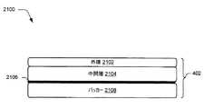
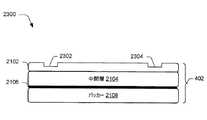
1つ以上の実装形態では、キーボードは、コンピュータ装置へのそれぞれの入力を開始するのに使用可能である複数のキーを含む感圧キーアセンブリと;複数のキーによって生成された信号をコンピュータ装置に通信するために、コンピュータ装置に物理的に且つ通信可能に、取外し可能に接続するように構成された接続部と;接続部をキーアセンブリに物理的に接続する可撓性ヒンジと;感圧キーアセンブリを覆うとともに、可撓性ヒンジの外面を形成するように構成された第1及び第2の外層であって、第1及び第2の外層は、接続部に固定されており、第1及び第2の外層の少なくとも一方が、伝熱フィルムを使用して感圧キーアセンブリに固定されている。 In one or more implementations, the keyboard includes a pressure sensitive key assembly that includes a plurality of keys that can be used to initiate respective inputs to the computing device; and signals generated by the plurality of keys to the computing device. A connection configured to physically and communicatively and removably connect to a computing device for communication; a flexible hinge physically connecting the connection to the key assembly; and a pressure sensitive key First and second outer layers configured to cover the assembly and to form an outer surface of the flexible hinge, the first and second outer layers being secured to the connection portion; At least one of the second outer layers is secured to the pressure sensitive key assembly using a heat transfer film.
この発明の概要は、以下の詳細な説明でさらに説明するような概念の選択を簡略化して表すために提供されている。この発明の概要は、特許請求の範囲に記載される主題の主要な特徴又は本質的な特徴を特定することを意図するものでも、特許請求の範囲に記載される主題の範囲を決定する助けとして使用されることを意図するものでもない。 This Summary is provided to simplify a selection of concepts that will be further described below in the Detailed Description. This summary is intended to identify key features or essential features of the claimed subject matter, but may assist in determining the scope of the claimed subject matter. It is not intended to be used.
詳細な説明を、添付の図面を参照して説明する。図面において、参照符号の左端の数字(複数)は、この参照符号が最初に表示される図面を特定する。明細書及び図面における様々な例における同一の参照符号の使用は、同様又は同一のアイテムを示す。図面に表されるエンティティは、1つ又は複数のエンティティを示すことができ、こうして参照が、この議論における単一又は複数形のエンティティについて区別なく行うことができる。 The detailed description is described with reference to the accompanying figures. In the drawings, the leftmost digit (s) of a reference number identifies the drawing in which this reference number is initially displayed. The use of the same reference symbols in various examples in the specification and drawings indicates similar or identical items. The entities represented in the drawings may indicate one or more entities, and thus references can be made without distinction for single or plural entities in this discussion.
概要
入力装置は、入力装置の厚さが約3.5mm又はこれより小さいような、薄いフォームファクタ(form factor)をサポートするように構成してもよい。しかしながら、このフォームファクタのため、このような装置を組み立てるために使用される従来技術は、この装置の層を組み付ける際に生じるしわ等のフォームファクタによって、不完全であった。Overview The input device may be configured to support a thin form factor, such that the thickness of the input device is about 3.5 mm or less. However, because of this form factor, the prior art used to assemble such devices has been incomplete due to form factors such as wrinkles that occur when assembling the layers of the device.
入力装置アセンブリ技術を説明する。1つ以上の実装形態では、入力装置の外層(例えば、織物、マイクロファイバー等)が、熱活性化フィルムや他の固定技術を使用してキーアセンブリ(例えば、感圧キーアセンブリ)に固定さる。熱活性化フィルムは、例えば、外層の織り内で溶融して、機械的な接合が層と共に形成されるように構成することができる。これは、引張力を生じさせた状態で、減圧下で、従来技術を使用して互いに層を固定する際に生じるしわや他の欠陥を排除するように行ってもよい。また、複数の外層を、同様の技術を用いて入力装置のエッジに互いに形成することができ、それによって強固な接合がそのエッジで形成される。これらの技術の更なる議論は、図27〜29に関して確認することができる。 An input device assembly technique will be described. In one or more implementations, the outer layer of the input device (eg, fabric, microfiber, etc.) is secured to the key assembly (eg, pressure sensitive key assembly) using a heat activated film or other fastening technique. The heat activated film can be configured, for example, to melt within the weave of the outer layer so that a mechanical bond is formed with the layer. This may be done to eliminate wrinkles and other defects that occur when the layers are secured to each other using conventional techniques under reduced pressure with the tensile force generated. Also, a plurality of outer layers can be formed on the edge of the input device using similar techniques, thereby forming a strong bond at the edge. Further discussion of these techniques can be confirmed with respect to FIGS.
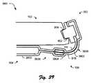
1つ以上の追加の実装形態では、コンピュータ装置との物理的な且つ通信可能な結合を形成するために使用可能な接続部に1つ以上の外層を取付ける技術を説明する。これらの技術は、例えば、1つ以上の外層で接続部の少なくとも一部に巻き付けられるステップを含んでもよい。これは、入力装置の接続部と入力部(例えば、キーボード)との間にセキュリティが保護されたセキュア接続を提供するだけでなく、入力部(例えば、キー)を覆う、ヒンジを形成する、及び接続部に取り付けるために使用される材料間の一貫性のあるルック・アンド・フィール(look and feel)を提供するために利用される。さらに、これらの技術は、本と同様に、入力装置の接続部と可撓性ヒンジとの動作をサポートするために利用することができ、それによって、コンピュータ装置と連動する入力装置を使用するユーザに使い易いユーザ体験を提供する。これらの技術や他の技術の更なる議論は、図30〜38に関して確認することができる。 One or more additional implementations describe techniques for attaching one or more outer layers to a connection that can be used to form a physical and communicable coupling with a computing device. These techniques may include, for example, wrapping around at least a portion of the connection with one or more outer layers. This not only provides a secure secure connection between the input device connection and the input (eg, keyboard), but also covers the input (eg, key), forms a hinge, and Used to provide a consistent look and feel between the materials used to attach to the connection. In addition, these techniques, like books, can be used to support the operation of the input device connection and the flexible hinge, thereby enabling users to use the input device in conjunction with a computer device. Provide an easy-to-use user experience. Further discussion of these and other techniques can be found with respect to FIGS.
以下の議論では、本明細書で説明する技術を用いるような例示的な環境を最初に説明する。例示的な環境だけでなく他の環境でも実行されるような例示的な手順を次に説明する。その結果、例示的な手順の性能は、例示的な環境に限定されるものではなく、例示的な環境は、例示的な手順の性能に限定されるものではない。また、入力装置を説明するが、カバー等の入力機能を含まない別の装置も企図される。 In the discussion that follows, an exemplary environment using the techniques described herein is first described. An exemplary procedure will now be described that may be performed in other environments as well as exemplary environments. As a result, the performance of the exemplary procedure is not limited to the exemplary environment, and the exemplary environment is not limited to the performance of the exemplary procedure. Also, although an input device is described, other devices that do not include an input function, such as a cover, are also contemplated.
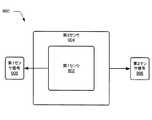
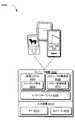
例示的な環境
図1には、本明細書で説明する技術を用いて動作可能にされるような、実装例の環境100が示されている。示される環境100は、可撓性ヒンジ106を介して入力装置104に物理的に且つ通信可能に結合されたコンピュータ装置102の例を含む。コンピュータ装置102は、様々な方法で構成してもよい。例えば、コンピュータ装置102は、携帯電話、示されるようなタブレット型コンピュータ等のモバイル使用のために構成してもよい。こうして、コンピュータ装置102は、実質的なメモリ及びプロセッサリソースを含むフルリソース装置から、制限されたメモリ及び/又は処理リソースを含む低リソース装置までの範囲の装置を含んでもよい。コンピュータ装置102は、コンピュータ装置102に1つ又は複数の動作を実行させるようなソフトウェアにも関する。Exemplary Environment FIG. 1 illustrates an
コンピュータ装置102は、例えば、入力/出力モジュール108を含むように示されている。入力/出力モジュール108は、コンピュータ装置102の入力処理及びレンダリング出力に関する機能を表す。多様な異なる入力、例えば、入力装置104のキーや、ジェスチャを識別するために表示装置110によって表示される仮想キーボードのキーに対応する機能に関する入力が、入力/出力モジュール108によって処理され、そして入力装置104及び/又は表示装置110のタッチスクリーン機能等を介して認識されたジェスチャに対応する動作を行う。こうして、入力/出力モジュール108は、キーの押下や、ジェスチャ等を含む入力タイプ同士の間の区切りを認識し且つ活用することで、多様な異なる入力技術をサポートすることができる。 The
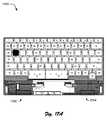
示される例では、入力装置104は、QWERTY配列のキーを有するキーボードとして構成されているが、他の配列のキーも企図される。さらに、ゲームコントローラや、楽器を模倣した構成等の他の非従来型の構成も企図される。こうして、入力装置104及び入力装置104に組み込まれたキーは、多様な異なる機能をサポートするために、多様な異なる構成を想定することができる。 In the example shown, the
前述したように、入力装置104は、この例では、可撓性ヒンジ106を使用することにより、コンピュータ装置102に物理的に且つ通信可能に結合している。可撓性ヒンジ106は、ヒンジによってサポートされる回転運動が、ピンによってサポートされるような機械的回転とは対照的に、ヒンジを形成する材料の屈曲(例えば、曲げ)を介して達成されるという意味において可撓性を有しているが、そのようなピンによってサポートされるような機械的回転の実施形態も企図される。さらに、この可撓性の回転によって、一方向(例えば、図面の垂直方向)の移動がサポートされているが、依然としてコンピュータ装置102に関して入力装置104の横方向の移動等の他の方向の移動を制限するように構成することができる。これを使用して、電力状態、アプリケーション状態等を変更するために使用されるセンサを整列させる等の、コンピュータ装置102に関して入力装置104の一貫した位置合わせをサポートすることができる。 As previously described, the
可撓性ヒンジ106は、例えば、1つ以上の織物層を用いて形成されており、入力装置104をコンピュータ装置102に通信可能に結合する及びその逆も同様に結合するような、可撓性配線として形成された導体部を含んでもよい。この通信は、例えば、キー押下の結果をコンピュータ装置102に通信し、コンピュータ装置から電力を受け取り、認証を実行し、コンピュータ装置102に補助電源を提供する等のために使用することができる。可撓性ヒンジ106は、様々な方法で構成してもよく、さらなる議論を以下の図面に関して行う。 The
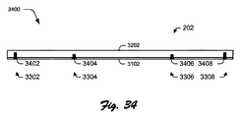
図2には、可撓性ヒンジ106をより詳細に示すような、図1の入力装置104の実装例200が示されている。この例では、入力装置102とコンピュータ装置104との間の通信可能な、物理的な接続を提供するように構成される、入力装置の接続部202が示されている。この例では、接続部202は、コンピュータ装置102のハウジングのチャネル内に受容されるように構成された高さ及び断面を有するが、この配置は、本発明の精神及び範囲から逸脱することなく逆転されることもある。 FIG. 2 illustrates an
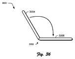
接続部202は、可撓性ヒンジ106の使用を介したキーを含むような入力装置104の一部に可撓性を示すように接続されている。こうして、接続部202が、コンピュータ装置に物理的に接続されるときに、接続部202及び可撓性ヒンジ106の組み合わせによって、ヒンジ結合されたブック(book)と同様にコンピュータ装置102に関して入力装置104の移動がサポートされる。 The
例えば、回転運動は、可撓性ヒンジ106でサポートされており、それによって、入力装置104は、コンピュータ装置102の表示装置110に対して配置されており、こうしてカバーとして機能することができる。入力装置104は、コンピュータ装置102の背後に配置されるように回転させることもでき、例えばコンピュータ装置102上の表示装置110とは反対側に配置されるような、コンピュータ装置102の後部ハウジングに配置される。 For example, rotational movement is supported by a
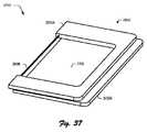
当然のことながら、他の様々な姿勢もサポートされる。例えば、コンピュータ装置102及び入力装置104は、これら両方の装置が、図1に示されるような面に対して平坦に置かれるような配置を想定してもよい。別の例では、タイピング装置は、入力装置104が面に対して平坦に置かれており、コンピュータ装置102が表示装置110の視聴を可能にするようなある角度で配置される、例えばコンピュータ装置102の背面に配置されたスタンドの使用を介してサポートされている。三脚構成、対面(meeting)構成、提案(presentation)構成等の他の例も企図される。 Of course, various other postures are also supported. For example, the
接続部202は、この例では、磁気結合装置204,206、機械的な結合突起部208,210、及び複数の通信用接点212を含むように示されている。磁気結合装置204,206は、1つ以上の磁石の使用を介してコンピュータ装置102の相補的な磁気結合装置に磁気的に結合されるように構成される。このように、入力装置104は、磁気吸引力の使用を介してコンピュータ装置102に物理的に固定されてもよい。 The
接続部202は、入力装置104及びコンピュータ装置102の間に機械的な物理的接続を形成するための機械的な結合突起部208,210も含んでいる。機械的な結合突起部208,210は、以下の図面により詳細に示される。 The
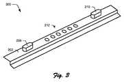
図3には、機械的な結合突起部208,210と複数の通信用接点212とを含むような、図2の接続部202の斜視図を表す実装例300が示されている。示されるように、機械的な結合突起部208,210は、接続部202の表面から離れる方向に延びるように構成されており、この場合には、垂直であるが、他の角度も企図される。 FIG. 3 shows an
機械的な結合突起部208,210は、コンピュータ装置102のチャネルの相補的なキャビティ内に受容されるように構成されている。そのように受容された場合であって、突起部の高さ及びキャビティの深さに対応するように規定された軸線と整列しないような力が加えられた場合に、機械的な結合突起部208,210によって、装置同士の間の機械的な結合が促進される。
例えば、突起部の高さ及びキャビティの深さに従うような、以前に説明した長手方向軸線と一致するような力を加えた場合に、ユーザは磁石によって単に加えられた力に打ち勝って、コンピュータ装置102から入力装置104を分離させる。しかしながら、他の角度では、機械的な結合突起部208,210は、キャビティ内で機械的に結合するように構成されており、こうして、磁気結合装置204,206の磁気力に加えて、コンピュータ装置102から入力装置104を取り外すのに抵抗するような力が形成される。このように、機械的な結合突起部208,210は、ブックからページを引き裂くことを模倣するようにコンピュータ装置102から入力装置104を取り外す力を付勢し、他の試みを制限して、装置を分離させる。 For example, when a force is applied that matches the longitudinal axis previously described, such as according to the height of the protrusion and the depth of the cavity, the user simply overcomes the force applied by the magnet The
接続部202は、複数の通信用接点212を含むようにも示されている。複数の通信用接点212は、装置同士の間に通信用接続を形成するために、コンピュータ装置102の対応する通信用接点に接触するように構成されている。通信用接点212は、入力装置104及びコンピュータ装置102の間に一貫した通信用接点を提供するように構成された、バネ仕掛けの複数のピンを使用する構成を介して、様々な方法で構成することができる。従って、通信用接点は、装置の押し合いによる小さな移動の間に、依然として通信用接続を提供するように構成することができる。コンピュータ装置102上のピン及び入力装置104上の接点の配置を含む、多様な他の例も企図される。
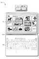
図4は、入力装置104の複数の層を斜視分解図400で示す。上面において、エンボス加工を使用して、下部キーの表示だけでなくキーの各機能の表示を提供するような、エンボス加工された織物(例えば、0.6mmのポリウレタン)を使用するように構成された外層402が示されている。 FIG. 4 shows a plurality of layers of the
力コンセントレータ(concentrator)404が、外層402の下に配置されている。力コンセントレータ402は、メカニカルフィルタ、パワーステアリングを提供するように構成されるとともに、以下の「力コンセントレータ」の項でさらに説明する下層コンポーネントの補助線(witness line)を非表示にするように構成される。 A
以下では、力コンセントレータ404は、この例では、感圧キーアセンブリ406である。感圧キーアセンブリ406は、以下の「感圧キー」の項でさらに説明するような、感圧キーを実装するために使用される層を含んでもよい。 In the following, the
支持層408が、感圧キーアセンブリ406の下に示されている。支持層408は、可撓性ヒンジ106及びその中に含まれる導体部を損傷からサポートするように構成されている。支持層408のさらなる議論は、「支持層」の項に関して確認することができる。 A
接着層410は、支持層408の下に配置されるとともに、入力装置104の入力部に機械的な剛性を加えるように構成された支持板412の上に配置されるように示されている。接着層410は、支持板412を支持層408に固定するような多様な方法で構成してもよい。接着層410は、例えば、この接着層の両面に接着剤の散点マトリックスを含むように構成してもよい。そのため、これらの層が一緒にロールされるとき、空気が脱出することが可能になり、それによって層間のしわや気泡が低減される。示される例では、接着層410は、例えばコントローラや、センサ、又は他のモジュールと、感圧キー及び/又は接続部202の通信用接点との間に、可撓性プリント回路配線をサポートするように構成されたネスト化チャネルも含む。以下では、支持板412は、PSAを含むバッカー層414及び外面416である。外面416は、他方の外面402と同一又は異なる材料から形成してもよい。 The
感圧キーアセンブリ
図5には、感圧キーアセンブリ406を形成するような、図2の入力装置104におけるキーボードの感圧キー500の断面図の一例が示されている。感圧キー500は、この例では、可撓性コンタクト層502(例えば、マイラー)を使用して形成されるように示されており、この可撓性コンタクト層502は、センサ基板504上に形成された、別のマイラー層として形成されるようなスペーサ層508,408を用いてセンサ基板504から離間されるように配置されている。この例では、可撓性コンタクト層502は、可撓性コンタクト層502に対する圧力の印加が存在しない状況下でセンサ基板504に接触していない。FIG. 5 illustrates an example of a cross-sectional view of a keyboard pressure
可撓性コンタクト層502は、この例では、センサ基板504に接触するように構成された、可撓性コンタクト層502の表面に配置された力感知インク510を含む。力感知インク510は、インクの抵抗量が、加えられる圧力の量との関係で直接的に変化するように構成される。力感知インク510は、例えば、可撓性コンタクト層502に対する圧力の印加の際に、センサ基板504に対して圧縮されるような比較的粗面で構成されてもよい。圧力の量が大きくなれば、力感知インク510がより多く圧縮され、それによって力感知インク510の導電性が増加し、抵抗が減少する。従って、他の種類の感圧性及び非感圧性の導体部を含む他の導電体も、本発明の精神及び範囲から逸脱することなく可撓性コンタクト層502上に配置することもできる。 The
センサ基板504は、可撓性コンタクト層502の力感知インク510によって接触するように構成される、その上に配置された1つ以上の導体部512を含む。接触した場合に、アナログ信号が、入力装置104及び/又はコンピュータ装置102によって処理されるように生成され、例えば、このアナログ信号がユーザによって意図されたものかを認識して、コンピュータ装置102への入力を提供する。様々な導電性材料(例えば、銀、銅)から形成された、多様な異なる種類の導体部512を、センサ基板504上に配置することができ、図9に関連してさらに説明するように多様な異なる構成で配置される。 The
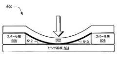
図6には、可撓性コンタクト層502の第1の位置に加えられた圧力によって、センサ基板504の対応する第1の位置で力感知インク510に接触するような、図5の感圧キー500の例600が示されている。この圧力は、図6の矢印の使用によって示されており、そしてユーザの手の指、スタイラス、ペン等の様々な方法で印加してもよい。この例では、矢印で示されるように圧力が加えられる第1の位置が、スペーサ層506,508の間に配置されており、可撓性コンタクト層502の中央部付近に位置している。この位置によって、可撓性コンタクト層502は、一般的に可撓性を示すと考えることができ、こうして圧力に応答することができる。 FIG. 6 illustrates the pressure sensitive key of FIG. 5 such that the pressure applied to the first position of the
この可撓性は、可撓性コンタクト層502の比較的大きな領域で可能になり、こうして力感知インク510は、センサ基板504の導体部512に接触する。こうして、比較的強い信号を生成することができる。また、可撓性コンタクト層502の可撓性がこの位置では比較的高いので、比較的大きな量の力を可撓性コンタクト層502を介して伝達させることができ、それによってこの圧力を力感知インク510に印加することができる。前述したように、この圧力の増加によって、力感知インクの導電性を対応して増加させ、この力感知インクの抵抗を減少させる。こうして、第1の位置における可撓性コンタクト層の比較的大きな量の可撓性によって、キーのエッジにより近接させて位置されるような可撓性コンタクト層502の他の位置に比較して、比較的強い信号を生成させることができる。この例は、以下の図面に関連して説明する。 This flexibility is possible in a relatively large area of the
図7には、可撓性コンタクト層502の第2の位置に加えられた圧力によって、センサ基板504の対応する第2の位置で接触するような、図5の感圧キー500の例700が示されている。この例では、圧力が加えられるような図6の第2の位置は、図5の第1の位置より感圧キーのエッジにより近接させて(例えば、スペーサ層508のエッジにより近接させて)位置している。この位置によって、可撓性コンタクト層502は、第1の位置と比較すると、可撓性が低下しており、こうして圧力にあまり反応しない。 FIG. 7 shows an example 700 of the pressure
この低下した可撓性によって、可撓性コンタクト層502の接触領域に減少が生じ、力感知インク510は、センサ基板504の導体部512に接触する。こうして、第2の位置で生成される信号は、図6の第1の位置で生成される信号よりも弱くなる。 This reduced flexibility causes a reduction in the contact area of the
さらに、可撓性コンタクト層502の可撓性がこの第2の位置で比較的低くなるため、比較的小さい量の力が可撓性コンタクト層502を介して伝達され、それにより力感知インク510に伝達される力の量が低下する。前述したように、この圧力の低下によって、力感知インクの導電性が対応して低下され、図5の第1の位置と比較してこの力感知インクの抵抗を増加させる。こうして、第1の位置と比較して、第2の位置における可撓性コンタクト層502の可撓性の低下によって、比較的弱い信号が生成される。さらに、この状況は、ユーザの指のより小さな部分が、図6の第1の位置と比較して、図7の第2の位置に圧力を印加させることができるような部分的なヒットによって悪化することがある。 Further, since the flexibility of the
しかしながら、前述したように、第1及び第2の位置においてスイッチによって生成された出力を正規化する技術を用いることができる。これは、図8に関して説明するような可撓性コンタクト層502の構成を介して、図9に関して説明するような複数のセンサの使用によって、図10に関して説明するようなセンサ基板504の構成によって、図11〜図13に関して説明するような力コンセントレータ層の使用によって、図14〜図16に関して説明するような固定具の使用によって、及び以下の段落に関して説明するようなこれらの組み合わせ等によって、様々な方法で行うことができる。 However, as described above, techniques for normalizing the output generated by the switch in the first and second positions can be used. This is due to the use of multiple sensors as described with respect to FIG. 9, through the configuration of
可撓性コンタクト層
図8には、スイッチの複数の位置で発生した出力を正規化するように構成された、単一の感圧キーの可撓性コンタクト層の例800が示されている。この例では、センサ基板504の導体部512に接触するように構成された、図5の可撓性コンタクト層502の「底面」又は「下側」の図が示されている。Flexible Contact Layer FIG. 8 shows an example 800 of a single pressure sensitive key flexible contact layer configured to normalize the output generated at multiple positions of the switch. In this example, a “bottom” or “bottom” view of the
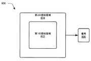
可撓性コンタクト層502は、第1及び第2の感知領域802,804を有するように示されている。第1の感知領域802は、この例では、図6において圧力が加えられる第1の位置に略対応しており、第2の感知領域804は、図7において圧力が加えられる第2の位置に略対応している。 The
前述したように、スイッチのエッジからの距離の変化による可撓性コンタクト層502の屈曲によって、距離がキーのエッジから増加するにつれて、比較的強い信号を生成することができる。従って、この例では、第1及び第2の感知領域802,804は、異なる位置で発生した信号806を正規化するように構成されている。これは、第1の感知領域802と比較して、第2の感知領域804においてより高い導電率及びより小さい抵抗を有するようにすることによって、様々な方法で行うことができる。 As described above, bending of the
導電性及び/又は抵抗の相違は、様々な技術を用いて達成することができる。例えば、力感知インクの1つ以上の初期層は、シルクスクリーン、印刷プロセス、又はこの力感知インクが表面に配置されるような他のプロセス等の使用を介して、第1及び第2の感知領域を804,802を覆うように可撓性コンタクト層502に適用することができる。1つ以上の追加の層が、次に、第2の感知領域704に適用されるが、第1の感知領域802に適用されない。 Differences in conductivity and / or resistance can be achieved using various techniques. For example, one or more initial layers of force sensing ink may be applied to the first and second sensing through the use of a silk screen, a printing process, or other process such that the force sensing ink is disposed on the surface. A region can be applied to the
これによって、第2の感知領域804が、所定の領域について、第1の感知領域802よりも多くの量(例えば、厚さ)の力感知インクを有するようにさせ、こうして導電性を対応して増加させ且つ抵抗を減少させる。従って、この技術は、異なる位置での可撓性コンタクト層502の可撓性の差を少なくとも部分的に打ち消すように機能することができる。この例では、第2の感知領域804での力感知インクの増加した高さによって、センサ基板504の導体部512との接触の生成に関与する屈曲量が低減するように作用し、これは信号を正規化するのに役立つ。 This causes the
第1及び第2の感知領域802,804における導電性及び/又は抵抗の相違は、他の様々な方法で達成してもよい。例えば、第1の力感知インクを、第1の感知領域802に塗布してもよいし、より高い導電率及び/又は抵抗を有する第2の力感知インクを、第2の感知領域804に塗布してもよい。さらに、第1及び第2の感知領域802,804の配置が、図8に同心状の正方形として示されているが、スイッチのコーナー部の感度をさらに高める、圧力に対して異なる感度を有する3つ以上の感知領域を使用する、導電率の勾配を使用する等、様々な他の配置を用いてもよい。単一のキーについて複数のセンサの使用をサポートする等の他の例も企図されており、これらの例は、以下の図面に関連して説明する。 Differences in conductivity and / or resistance in the first and
図9には、異なる位置での圧力を検出するために複数のセンサを含むような、図5の感圧キー500の例900が示されている。前述したように、ミスヒット及び可撓性の制限によって、感圧キーのエッジにおける性能が低下する。 FIG. 9 shows an example 900 of the pressure
従って、この例では、第1のセンサ902及び第2のセンサ904をそれぞれ用いて、第1及び第2のセンサ信号906,908をそれぞれ提供する。さらに、第2のセンサ904は、第1のセンサ902より感度を増加する(例えば、より高い導電率及び/又はより低い抵抗を有する)ように構成される。これは、異なる導体部、及びセンサ基板504の一部でセンサとして作動するような導体部の構成を介して、様々な方法で達成され得る。センサ基板504の他の構成は、キーの異なる位置において感圧キーによって生成された信号を正規化することができ、この例は、以下の図面の議論に関連して説明する。 Accordingly, in this example, the
センサ基板
図10には、感圧キーの異なる位置で発生した信号を正規化するように構成された、センサ基板504の導体部512の例が示されている。この例では、センサ基板504の導体部512は、互いに組み合わされた指状配線の第1及び第2の部分1002,1004として構成される。表面積、導体部の量、及び導体部同士の間のギャップが、この例では、センサ基板504の異なる位置での感度を調整するために使用されている。Sensor Board FIG. 10 shows an example of a
例えば、第1の位置1006に加えられる圧力によって、可撓性コンタクト層502の力感知インク510の比較的大きな領域を、センサ基板504の第2の位置1008よりも導電体に接触させる。図示の例に示されるように、第1の位置1006で接触した導体部の量は、ギャップ間隔及び導体部サイズを使用して、第2の部分1006において接触した導体部の量によって正規化される。こうして、より小さい導体部(例えば、より薄いフィンガー)及びキーのエッジとは反対側のキーの中央におけるより大きなギャップを使用することにより、キーの特有の性能特性は、一揃いの(suite)典型的なユーザの入力シナリオに調整することができる。また、センサ基板504を構成するこれらの技術は、正規化及び所望されるユーザ入力シナリオをさらに促進するために、可撓性コンタクト層502を構成するために説明される技術と組み合わせてもよい。 For example, the pressure applied to the
再び図2に戻ると、これらの技術は、入力装置104のキーボードの第1のキーによって生成された信号を、キーボードの第2のキーによって生成された信号で正規化するために、異なるキーの所望される構成を正規化し且つサポートするのに活用することができる。図2のQWERTY配列に示されるように(これは、他の配置にも等しく適用可能であるが)、ユーザは、より大きなタイピング圧力を、装置のエッジにより近接させて位置されたキーよりも入力装置104の中央に位置されたキーのホーム列に印加する可能性が高い。これは、シフトキー行のユーザの手の指の爪を使用する開始だけでなく、数字に到達するために増加した距離、様々な指(人指し指対小指)の異なる指の強さ等を含み得る。 Returning again to FIG. 2, these techniques use different keys to normalize the signal generated by the first key of the keyboard of the
従って、上述した技術は、ホーム列キーに関して数字キーの感度を高めるために、これらのキー同士の間の信号を正規化するために適用され、人差し指キー(例えば、文字「f」、「g」、「h」及び「j」)とは反対側の「小指」キー(例えば、文字「a」、及びセミコロンキー)の感度を高めること等ができる。他の様々な例は、より小さな表面領域を有するキー(例えば、図中の削除ボタン)を、シフトキー、スペースバー等のより大きな表面領域を有するキーと比較して、より高い感度を有するキーを作製する等の、感度を変化させることも企図される。 Thus, the techniques described above are applied to normalize the signal between these keys in order to increase the sensitivity of the numeric keys with respect to the home column key, and the index finger keys (e.g., the letters “f”, “g”). , “H” and “j”), the sensitivity of the “little finger” key (for example, the letter “a” and the semicolon key) on the opposite side can be increased. Various other examples include keys with higher sensitivity compared to keys with a smaller surface area (eg, the delete button in the figure) compared to keys with a larger surface area such as shift keys, spacebars, etc. It is also contemplated to change the sensitivity, such as making.
力コンセントレータ
図11には、図5の力コンセントレータ404を用いるような、図5の感圧キーの例1100が示されている。力コンセントレータ404は、力コンセントレータ層1102とパッド1104とを含む。力コンセントレータ層1102は、可撓性コンタクト層502に対して屈曲可能となるような可撓性材料(例えば、マイラー)等の、多様な材料から構成してもよい。力コンセントレータ層404は、可撓性コンタクト層502を、センサ基板504だけでなく他の機構に接触させる一貫性を改善するために用いることができる。Force Concentrator FIG. 11 shows an example 1100 of the pressure sensitive key of FIG. 5 that uses the
上述したように、力コンセントレータ層1102は、この例では、力コンセントレータ層1102の表面から隆起する、その上に配置されたパッド1104を含む。こうして、パッド1104は、可撓性コンタクト層502と接触させるための突起部として構成されている。パッド1104は、基板自体の一体化部分として、力コンセントレータ層1102(例えば、マイラー)の基板上に層として形成される(例えば、印刷、堆積、形成等)等、様々な方法で形成してもよい。 As described above, the
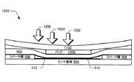
図12には、力コンセントレータ層1102の複数の異なる位置に加えられた圧力によって、可撓性コンタクト層502をセンサ基板504に接触させるような、図11の感圧キーの例1200が示されている。圧力が、矢印を使用することによって再び示されており、この例では、第1、第2及び第3の位置1202,1204,1206を含んでおり、これらの位置は、キーのエッジ、例えばスペーサ層508,508によって規定されたエッジにそれぞれより近接して所定距離に位置決めされている。 FIG. 12 illustrates the pressure sensitive key example 1200 of FIG. 11 such that the pressure applied to a plurality of different locations on the
図示されるように、パッド1104は、可撓性コンタクト層502がスペーサ層508,508の間で屈曲可能になるように、サイズ決めされる。パッド1104は、増加した機械的剛性を提供するように構成されており、こうして、力コンセントレータ層1102の基板(例えば、マイラー)と比較して、曲げ及び屈曲に対する抵抗が改善される。従って、パッド1104が可撓性コンタクト層502に押し付けられる場合に、可撓性コンタクト層502は、図12と、図6及び図7との比較によって示されるように、減少した曲げ半径を有する。 As shown,
こうして、パッド1104の周りの可撓性コンタクト層502の曲げによって、力感知インク510とセンサ基板504の導体部512との間に比較的一貫性のある接触領域を促進することができる。これによって、キーによって生成される信号の正規化を促進することができる。 Thus, bending of the
パッド1104は、圧力源の接触面積を拡げるために作用することもできる。ユーザは、例えば、指の爪、或いはスタイラスや、ペン、又は比較的小さな接触領域を有する他の物体の先端を用いて、力コンセントレータ層1102を押し付けることができる。前述したように、これは、センサ基板504に接触する、可撓性コンタクト層502の対応する小さい接触領域をもたらし、こうして信号強度が対応して低下する。 The
しかしながら、パッド1104の機械的剛性によって、この圧力は、可撓性コンタクト層502と接触するようなパッド1104の領域に亘って拡がることができ、その圧力は、次にセンサ基板504に接触させるためにパッド1104の周囲で対応して曲げられるような、可撓性コンタクト層502の領域に亘って拡がる。このように、パッド1104は、可撓性コンタクト層502と、感圧キーによって信号を生成するために使用されるようなセンサ基板504との間の接触領域を正規化するために使用することができる。 However, due to the mechanical stiffness of the
パッド1104は、たとえこの圧力が「オフセンター(off center)」に印加されても、圧力を導くようにも作用する。図6及び図7に関連して前述したように、可撓性コンタクト層502の可撓性は、感圧キーのエッジ、例えばこの例ではスペーサ層508,508によって規定されるエッジから所定距離に少なくとも部分的に依存してもよい。 The
しかしながら、パッド1104を使用して、可撓性コンタクト層502に圧力を導き、比較的一貫した接触を促進することができる。例えば、力コンセントレータ層1102の略中央領域に位置決めされた第1の位置1202に加えられた圧力によって、パッド1104のエッジに位置決めされた第2の位置1204に圧力が印加されたときに達成された接点と同様の接触が生じる。パッド1104によって規定された力コンセントレータ層1102の領域外部に加えられた圧力は、パッド1104によって規定される領域の外側に位置付けされる第3の位置1206であるがキーのエッジ内にあるように、パッド1104を使用して導かれる。スペーサ層508,508によって規定された力コンセントレータ層1102の領域の外側に位置付けされた位置は、可撓性コンタクト層502をセンサ基板504に接触させるように導かれ、この例は、以下の図面に関連して規定される。 However, the
図13には、力コンセントレータを用いる複数の感圧キーを含むような、キーボード1300の断面図の例が示されている。キーボード1300は、この例では、第1及び第2の感圧キー1302,1304を含む。感圧キー1302,1304は、前述したように、力コンセントレータ層1102、可撓性コンタクト層502、センサ基板504、及びスペーサ層508を共有している。感圧キー1302,1304のそれぞれは、この例では、圧力を導いて、可撓性コンタクト層502及びセンサ基板504のそれぞれの部分の間に接触を生じさせるように構成された、それぞれのパッド1306,1308を有している。 FIG. 13 shows an example of a cross-sectional view of a
前述したように、従来の感圧キーのエッジにおける制限された可撓性によって、キーのエッジに加えられる圧力を認識するためのキーの不能性が生じる。これは、入力装置104が加えられた圧力を認識できないような「デッドゾーン」を生じさせる。しかしながら、力コンセントレータ層1102の使用及びパッド1306,1308によってサポートされる圧力のチャネリングにより、デッドゾーンの存在が減少され、さらに排除することができる。 As previously mentioned, the limited flexibility at the edge of a conventional pressure sensitive key creates the inability of the key to recognize the pressure applied to the key edge. This creates a “dead zone” where the
例えば、位置1310は、第1及び第2の感圧キー1302,1304の間に配置された、矢印を使用することによって示されている。この場合には、位置1310は、スペーサ層508上に配置されており、且つ第2の感圧キー1304よりも第1の感圧キー1302に近接して配置されている。 For example, the
従って、第1の感圧キー1302のパッド1306は、第2の感圧キー1304のパッド1308よりも多くの量の圧力を導くことができる。これによって、第1の感圧キー1302で生成された信号が第2の感圧キー1304より強くなり、信号は、第1の感圧キー1302において生成されるが、第2の感圧キー1304で生成されない。それにも拘わらず、入力装置104のモジュール及び/又はコンピュータ装置102は、キーによって生成された信号を処理することによってどのキーが使用されたかに関するユーザの可能性のある意図を判定することができる。このように、力コンセントレータ層1102は、チャネリングを通してキーをアクティブにするように使用された領域を増加することによって、キー同士の間に位置するデッドゾーンを抑制することができる。 Accordingly, the pad 1306 of the first pressure sensitive key 1302 can conduct a greater amount of pressure than the pad 1308 of the second pressure
力コンセントレータ層1102を使用して、キーに対して加えられた圧力のメカニカルフィルタリングを実行することもできる。ユーザは、例えば、文書をタイピングするときに、キーの表面に手の1つ又は複数の指を置くが、キーをアクティブにするのを望まないことを選択することができる。力コンセントレータ層1102がなければ、従って、感圧キーからの入力の処理が、キーに加えられる圧力の量及び/又は持続時間によって、キーを活性化することが意図されているかどうかを判定することによって複雑にされる。 The
しかしながら、この例では、力コンセントレータ層1102は、キーをアクティブにするのをユーザが意図しそうにないような入力をメカニカルフィルタリングするように、可撓性コンタクト層を使用し且つ構成することができる。力コンセントレータ層1102は、例えば、可撓性コンタクト層502との組み合わせで、キーを作動させるために使用される圧力の量を規定するような、閾値を用いるように構成してもよい。これは、可撓性コンタクト層502及びその上に配置された力感知インク510を、センサ基板の導体部512に接触させて、入力装置104及び/コンピュータ装置102による入力として認識可能である信号を生成する、のに十分な圧力の量を含むことができる。 However, in this example,
一実装形態では、この閾値は、約50グラム以下の圧力では、力コンセントレータ層1102及び可撓性コンタクト層502に信号を開始させるのに十分でないように設定されるが、その閾値を超える圧力では入力として認識可能になるように設定される。静止圧と打キーについて区別するように構成された様々な他の実装形態及び閾値も企図される。 In one implementation, this threshold is set such that pressures below about 50 grams are not sufficient to cause the
力コンセントレータ層1102は、他の様々な機能を提供するように構成されている。入力装置104は、例えば、図4に関連して前述したように、例えば文字、数字等のそれぞれのキーの操作の表示、及び「シフト」、「リターン」、ナビゲーション等の他の操作の表示を有するような外層402(例えば、織物)を含むことができる。力コンセントレータ層1102は、この層の下に配置することができる。さらに、外層402に向けて露出されるような力コンセントレータ層1102の側は、実質的に円滑となるように構成することができ、それによって、入力装置104の下層コンポーネントからもたらされる補助線を削減し且つさらに排除する。 The
このように、外層402の表面は、均一性を向上させて作製されており、こうして、例えば下層コンポーネントからの干渉なしに円滑な触覚を促進することにより、高い精度でより良いタイピング体験を提供することができる。力コンセントレータ層1102は、入力装置104の下層コンポーネントへの静電放電(ESD)から保護するようにも構成されている。例えば、入力装置104は、図1及び図2に示されるような、トラックパッドを含んでもよく、こうしてトラックパッドに亘る運動を静的に生成することができる。しかしながら、力コンセントレータ層1102は、この潜在的なESDから層の下に露出された、入力装置104のコンポーネントを保護することができる。このような保護の他の様々な例は、本発明の精神及び範囲から逸脱することなく企図される。 In this way, the surface of the
支持層
図14には、可撓性ヒンジ106の動作をサポートするだけでなく、この動作中に入力装置104のコンポーネントを保護するように構成された、支持層408を表す実装例1400が示されている。前述したように、可撓性ヒンジ106は、異なる形態をとるように様々な程度の曲げをサポートするように構成することができる。しかしながら、可撓性ヒンジ106の外層402,416を形成するような、可撓性ヒンジ106を形成するために選択された材料は、所望される「ルック・アンド・フィール(look and feel)」をサポートするように選択することができるが、引き裂き及び引き伸ばしに対する所望の弾力性を提供することができない。Support Layer FIG. 14 shows an
従って、このような場合には、これは、入力装置104のキー及び他のコンポーネントをコンピュータ装置102に通信可能に結合するために使用される、導体部1402の操作性に影響を及ぼす。例えば、ユーザが、入力装置104を片手で把握して、突起部208と磁石によってサポートされた磁気吸引とを解放することにより、コンピュータ装置102からその入力装置104を引き離すことができる。従って、これは、第1又は第2の外層402,416又は他の構造からの十分なサポートなしに、それら入力装置及びコンピュータ装置を分断させるのに十分である力の量を導体部に印加することができる。 Thus, in such a case, this affects the operability of the
従って、入力装置104は、可撓性ヒンジ106及び入力装置104の他のコンポーネントを保護するように構成された支持層408を含んでもよい。例えば、支持層408は、外層402,416を形成するために使用される材料よりも引き裂き及び引き伸ばしに高い抵抗を有する材料、例えばマイラーとしても知られている二軸延伸ポリエチレンテレフタレート(BoPET)で形成することができる。 Accordingly, the
支持層408により提供されるサポートは、こうして、可撓性ヒンジ106の外層402,416を形成するために使用される材料を保護するのに役立つ。支持層408は、接続部202をキーに通信可能に結合するために使用される導体部1402等の、ヒンジを介して配置されたコンポーネントを保護するのに役立つ。 The support provided by the
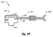
示される例では、支持層408は、図1に示されるようなキー、トラックパッド等を含むような、入力装置104の入力部914の一部として配置されるように構成された部分1404を含む。支持層408は、接続部202に固定するべく、部分1404から可撓性ヒンジ106を介して延びるように構成された第1及び第2タブ1406,1408も含む。タブは、接続部202にタブを固定するために突起(例えば、ネジ、ピン等)が挿入されるような、図示されるように1つ以上の孔を含むように、様々な方法で固定されもよい。 In the example shown, the
第1及び第2のタブ1406,1408は、この例では、接続部202の略両端で接続するように構成され且つ示されている。このようにして、例えば接続部202によって規定される長手方向軸線に対して垂直になるような望ましくない回転運動が制限される。こうして、可撓性ヒンジ106及び接続部202の相対的な中間点に配置された導体部1402は、引き裂き、引き伸ばし、及び他の力からも保護される。 The first and
この例で説明される支持層408は、中間スパイン(spine)の機械的剛性を高めるとともに最小曲げ半径をサポートするために、中間スパインの一部を形成するように構成された中間スパイン部分1410も含む。第1及び第2のタブ1406,1408が示されているが、より多くの又はより少ないタブが、説明される機能をサポートするために支持層408によって用いられることは容易に理解できるであろう。 The
接着剤
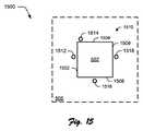
図15には、キーのエッジに沿って複数の位置に固定された可撓性コンタクト層502を有するような、図5の感圧キーの底面図1500が示されている。第1、第2、第3、及び第4エッジ部1502,1504,1506,1508は、この例では、感圧キーのスペーサ層508の開口部1510を規定するように示されている。図5〜図7に関連して説明したような開口部1510によって、可撓性コンタクト層502が開口部1510を通って屈曲(例えば、曲げ及び/又は引き伸ばし)することが可能になり、それによってセンサ基板504の1つ以上の導体部512に接触する。Adhesive FIG. 15 shows a
示される例では、第1の固定部分1512が、開口部1510の第1のエッジ1512の近くに配置されるように示されている。同様に、第2、第3、第4の固定部分1514,1516,1518が、開口部1510の第2、第3、及び第4のエッジ1504,1506,1508のそれぞれの近くに配置されるように示されている。固定部分は、接着剤、機械的固定装置(例えば、ピン)等の使用を介して、様々な方法で構成してもよい。例えば、接着剤は、一連のドット形状又は他の形状としてスペーサ層508に塗布することができ、次に可撓性コンタクト層502に接触され(例えば、押し付けられ)てもよい。 In the example shown, the
可撓性コンタクト層502をスペーサ層508に固定するために使用される技術にも拘わらず、可撓性は、開口部のエッジに沿った可撓性コンタクト層502の一部を固定されないままにすることにより、所望されるように構成してもよい。例えば、第1及び第2の固定部分1514,1516は、可撓性コンタクト層502が、それぞれの第1及び第2のエッジ1502,1504に沿ってスペーサ層508に固定されるような領域を唯一規定する。従って、可撓性コンタクト層502の可撓性は、圧力の接点と固定部分との間の距離が、可撓性コンタクト層をエッジ上に摺動させることによって、図6及び図7のエッジの議論と同様に減少するにつれて、低下し、向上したストレッチ(引き伸ばし)性が可能になる。 Despite the technique used to secure the
しかしながら、その逆も、可撓性が増加するという意味で真であり、さらに減少した圧力が固定部分から印加される。こうして、開口部1510のエッジに沿った可撓性は、可撓性コンタクト層502がスペーサ層508に(近くに)固定されないような、エッジに沿った部分を含めることによって増加させることができる。こうして、可撓性コンタクト層502がスペーサ層404にどのように固定されるかの様々な配置を使用して、可撓性コンタクト層502の異なる位置での異なる量の可撓性をサポートすることができる。 However, the converse is also true in the sense that the flexibility is increased, and a further reduced pressure is applied from the fixed part. Thus, the flexibility along the edge of the
例えば、示されるように、第1及び第2の固定部分1512,1514は、第1及び第3の固定部分1512,1516よりも一緒により近接して位置される。従って、第1及び第3の固定部分1512,1516の間の点(例えば、中間点)は、第1及び第2の固定部分1512,1514の間の対応する点(例えば、中間点)よりも大きな可撓性を有する。このように、設計者は、所望されるように、特定の位置等での可撓性を増減させるように可撓性コンタクト層502を構成することができる。 For example, as shown, the first and
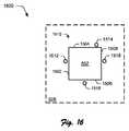
図16の例1600では、例えば、第2の固定部分1514は、第2エッジ1504の一端部から第2エッジ1504の反対側端部に移動する。こうして、可撓性は、この例では、キーの左上部では増加し、キーの右上部では減少する。他の多様な例も企図されており、この例は、以下の例のキーボードに関連して示す。 In the example 1600 of FIG. 16, for example, the second fixed
図17Aには、異なる配置の接着剤が異なるキーに使用されるような、複数のキーを有するキーボードの一部として塗布された接着層1700の例が示されている。この例では、固定部分は、可撓性コンタクト層502をスペーサ層506で固定するように使用された、接着剤の黒い線や点で示されている。示されるように、固定部分の様々な配置が、対応するキーがどの位押下されるかの違いに対処するために使用される。 FIG. 17A shows an example of an
例えば、示されるように、ホーム行(例えば、キー43〜55)のそれぞれのキーについての接着剤の配置は、次の下の行のキーの列、例えばキー56〜67についての接着剤の配置とは異なる。これは、キーの中央、又はキーの4つの側面のうちの特定1つにおいて、「どこで」キーが押下されるかに対処するために行うことができる。これは、ユーザの指の爪とは対照的に指の指球を使用するように、ユーザの指が押下するキーが「どのように」押下されるかに対処するために行うことができる。こうして、図17の接着層1700の例に示されるように、異なる配置は、異なる行キーだけでなく、異なる列キーについても使用することができる。 For example, as shown, the adhesive placement for each key in the home row (eg, keys 43-55) is the adhesive placement for the key row in the next lower row, eg, keys 56-67. Is different. This can be done to address where the key is pressed in the middle of the key, or in a particular one of the four sides of the key. This can be done to deal with "how" a key pressed by the user's finger is pressed, such as using a finger ball as opposed to a user's fingernail. Thus, as shown in the example of
接着層1700は、この例では、第1及び第2の圧力等化装置1702,1704を形成するようにも示されている。この例では、接着剤は、接着剤の間に形成されたチャネルを残すように配置される。こうして、接着剤は、装置を形成するチャネルを規定する。チャネルは、可撓性コンタクト層502とセンサ基板504との間に感圧キーの一部として形成された開口部1510を、入力装置104の外部環境に接続するように構成される。
このように、空気は、チャネルを介して外部環境と開口部との間で移動して、空気圧を略均等化することができ、例えば飛行機の中で空気圧が減少した状況に直面したときに、入力装置104への損傷を防止するのに役立つ。1つ以上の実装形態では、チャネルは、圧力均等化装置1702,1704から開口部1510に通過した外部汚染物質から保護するために、複数の屈曲部を有するラビリンスとして形成してもよい。示される例では、圧力均等化装置1702,1704は、スペーサ層の掌のパームレストの一部として配置されており、利用可能なスペースを活用してより長いチャネルを形成し、こうして汚染物質からさらに保護する。当然ながら、他の多種多様な例及び位置も、本発明の精神及び範囲から逸脱することなく企図される。 In this way, the air can move between the external environment and the opening through the channel to substantially equalize the air pressure, for example when facing a situation where the air pressure has decreased in an airplane, Helps prevent damage to the
図17Bは、閉じ込められる気泡を減少させるために使用されるようなマトリックスを組み込む層1750の別の実装例を示しており、この層1750は、図4の接着層410に対応してもよいし、そうでなくてもよい。この例では、戦略的な接着剤配置(又は他の固定技術)が、連続した層の間に閉じ込められた気泡を減らすために使用される。以前の例では、センサ基板/可撓性コンタクト層インターフェイス内の通気口付のラビリンスシールが、説明されていた。 FIG. 17B shows another implementation of a
この例では、(例えば、センサ基板202の下の)層は、「フルブリード(全面に塗布された)接着シート」として構成されていないが、代わりに、連続した層を一緒に結合させる正方行列状の接着剤のパッチである。これによって、容易なアセンブリが可能になり、且つ層間に閉じ込められた空気溜まりを排除することを可能にする。このように、複数の層が、薄いプロファイル、剛性を達成するために接着剤構造を介して一緒に結合されており、コンポーネントの内部電子部品のネスト化を可能にする。 In this example, the layers (e.g., below the sensor substrate 202) are not configured as "full bleed adhesive sheets", but instead a square matrix that joins successive layers together. Adhesive patch. This allows easy assembly and eliminates air pockets trapped between the layers. In this way, multiple layers are joined together through an adhesive structure to achieve a thin profile, stiffness, allowing for the nesting of the internal electronic components of the component.
ネスト化
図18には、入力装置104の機能をサポートするため使用されるような表面実装式ハードウェア要素1802の例1800が示されている。入力装置104は、多様な機能をサポートするために、様々な方法で構成してもよい。例えば、入力装置104は、図5〜図7に関連して説明したような感圧キー、図1に示されるようなトラックパッド、又は機械的な切換式キー、生体認証リーダー(例えば、指紋リーダー)等の他の機能を含むように構成してもよい。Nesting FIG. 18 shows an example 1800 of a surface
従って、入力装置104は、この機能をサポートするために、多様な異なるタイプの表面実装式ハードウェア要素1802を含んでもよい。例えば、入力装置104は、多様な異なる操作を実行するために活用されるプロセッサ1804を含んでもよい。このような操作の例は、特定のキーストロークを識別するために、図5の感圧キー500又は他のキー(例えば、感圧式ではない機械的な切換えキー)で生成された信号を、ヒューマンインターフェイス装置(HID)のコンプライアント入力内で処理することを含んでもよい。こうして、この例では、入力装置104は、信号の処理を実行し、且つこの処理結果を入力としてコンピュータ装置102に提供することができる。このように、コンピュータ装置102及びそのソフトウェアは、コンピュータ装置102のオペレーティングシステムによって、変更することなしに入力を容易に識別することができる。 Accordingly, the
別の例では、入力装置104は、1つ又は複数のセンサ1806を含んでもよい。センサ1806は、例えば、入力装置104の運動及び/又は姿勢を検出するために活用することができる。このようなセンサ1806の例としては、加速度計、磁力計、慣性測定ユニット(IMUs)等が挙げられる。 In another example,
さらなる例では、入力装置104は、タッチコントローラ1808を含むこともでき、このタッチコントローラ1808を使用して、キーボードの1つ又は複数のキー、トラックパッド等を用いて検出されたタッチ入力を処理することができる。さらに別の例では、入力装置104は、入力装置104の電子コンポーネントのための比較的安定した電圧を維持するために1つ又は複数の線形レギュレータ1810を含んでもよい。 In a further example, the
入力装置104は、認証集積回路1812も含むこともできる。認証集積回路1812は、コンピュータ装置102と一緒に作動させるための入力装置104を認証するように構成することができる。この認証は、認証を行うために、入力装置104及び/又はコンピュータ装置102によって処理されるような、装置間の秘密を共有するように様々な方法で実行することができる。様々な他1814の表面実装式ハードウェア要素1802は、種々の異なる機能をサポートすることも企図される。
前述したように、しかしながら、従来技術を使用する表面実装式ハードウェア要素1802の包含は、入力装置104の全体の厚さに不利な影響を与えることがある。しかしながら、本明細書で説明する1つ以上の実装形態では、入力装置104の層は、この影響を緩和するために、ネスト化技術を含んでもよく、更なる議論が以下の図に関して行われる。 As previously mentioned, however, the inclusion of surface
図19には、図18の表面実装式ハードウェア要素1802が、入力装置104の1つ以上の層内にネスト化されるような、実装例1900が示されている。前述したように、入力装置は、マイクロファイバー等を使用した構成を介して所望の触感をユーザに与えるように形成された上部外層402と下部外層416とを含んでもよい。外層402は、例えば、エンボス加工を使用して、下部キーの表示だけでなく、キーの各機能を示す表示を提供するために、エンボス加工された織物(例えば、0.6mmポリウレタン)を使用して構成してもよい。 FIG. 19 illustrates an
力コンセントレータ404は、第1及び第2の感圧キー1302,1304をそれぞれサポートするために、力コンセントレータ層1102と複数のパッド1306,1308とを含む外層402の下に配置されている。力コンセントレータ404は、メカニカルフィルタ、パワーステアリングを提供し、下層コンポーネントの補助線を非表示にするように構成することができる。 The
この例では、感圧キーアセンブリ406は、力コンセントレータ層1102のパッド1306,1308の下に配置されているが、力コンセントレータ404を利用していないような他の例も企図される。感圧キーアセンブリ406は、感圧キーを実装するために使用される層を含む。図5で説明したように、例えば、可撓性コンタクト層502は、力感知インクを含んでもよく、屈曲を介して可撓性コンタクト層502を、センサ基板504の1つ以上の導体部に接触させて、入力を開始するために使用可能な信号を生成する。 In this example, the pressure sensitive
センサ基板504は、様々な方法で構成されてもよい。示される例では、センサ基板504は、1つ以上の導体部が、プリント回路基板(PCB)上の配線として実装されるように構成される第1の側を含む。表面実装式ハードウェア要素1802は、第1の側とは反対側であるセンサ基板504の第2の側に取り付けられている。 The
表面実装式ハードウェア要素1802は、例えば、センサ基板504を介してセンサ基板504の第1の側の1つ以上の導体部に通信可能に結合されてもよい。表面実装式ハードウェア要素1802は、次に、生成された信号を処理して、この信号をコンピュータ装置102によって認識可能であるHIDコンプライアント入力に変換することができる。 The surface
これは、ユーザの可能性のある意図を判定するためにアナログ信号を処理して、例えば、ミスヒット、複数のキーからの信号を同時に処理する、掌用の拒絶閾値を実装する、キーが押下されたかを示す閾値が超過したか否かを判断する等を含む。図18に関連して前述したように、入力装置104の表面実装式ハードウェア要素を用いて実装された様々な他の機能上の例は、本発明の精神及び範囲から逸脱することなく企図される。 It processes analog signals to determine the user's possible intentions, eg, implements a rejection threshold for palms, processing signals from multiple hits simultaneously, signals from multiple keys, key presses For example, determining whether or not a threshold value indicating whether or not it has been performed has been exceeded. As described above in connection with FIG. 18, various other functional examples implemented using surface mount hardware elements of
入力装置104の全体の厚さでの表面実装式ハードウェア要素1802の高さの影響を低減させるために、表面実装式ハードウェア要素1802は、入力装置104の他の層の1つ以上の孔を介して配置される。この例では、表面実装式ハードウェア要素1802は、支持層408及び接着層410を介して形成されるとともに少なくとも部分的に支持板412を介して形成された孔を介して配置されている。別の例が図4にも示されており、孔は、支持層408、接着層410、及び支持板412のそれぞれを介して全体に形成されている。 In order to reduce the effect of the height of the surface
従って、この例では、バッカー層414介した力コンセントレータ層1102の入力装置104の層、及びこれらの間に配置された層の全体の厚さは、約2.2mm以下の厚さを有するように構成することができる。また、外層402,416について選択した材料の厚さに依存して、感圧キーにおける入力装置104の全体の厚さは、約3.5mm以下となるように構成することができる。当然のことながら、他の厚さも、本発明の精神及び範囲から逸脱することなく企図される。 Accordingly, in this example, the total thickness of the
キー構成
図20には、複数のキーを含むような図1の入力装置104の外面402の上面図を表す実装例2000が示されている。この例では、入力装置の外面402は、キーボードの複数のキーを覆うように構成されており、これらの例は、文字「j」、「k」、「l」、及び「m」として示されているが、当然のことながら、数字、句読点、様々な言語やレイアウト、機能(例えば、ピアノのキーボード、ゲームコントローラ)等の他のキーや対応する機能も企図される。Key Configuration FIG. 20 illustrates an
前述したように、薄いフォームファクタをサポートするように入力装置を構成するために利用された従来技術は、装置の特定のキーの位置及び識別の困難性に起因して、この装置と相互作用する場合(例えば、タイプ等)に非効率的で望ましくないユーザ経験をもたらす。しかしながら、この項及び他の項で説明する技術を用いて、入力装置104を用いたユーザ経験を助けることができる。 As previously mentioned, the prior art utilized to configure an input device to support a thin form factor interacts with this device due to the particular key location and identification difficulties of the device. In some cases (e.g., type) results in an inefficient and undesirable user experience. However, the techniques described in this and other sections can be used to assist the user experience with the
この例では、キーは、角が丸められた矩形としてキーの境界を表すように示されているが、以前に説明したキー400のスペーサ層506のエッジに対応してもよい。当然のことながら、境界は、キーの1つ以上のエッジに沿ったライン、一連のドット等の他の様々な方法で示すことができる。 In this example, the keys are shown to represent the key boundaries as rectangles with rounded corners, but may correspond to the edges of the
境界の形状及びパターンがどのように示されるかに拘わらず、表示は、ユーザがユーザの手の1本以上の指を使用してキーを位置付けできるように触覚フィードバックを提供するように構成してもよい。例えば、境界は、外層402の表面から「突き出た」一連の突起部を介して示すことができる。別の例では、エンボス加工技術を使用して、境界を示すために、外層402に凹部を形成してもよく、さらなる議論が、図23に関連して開始される。 Regardless of how the shape and pattern of the border is shown, the display is configured to provide tactile feedback so that the user can position the key using one or more fingers of the user's hand. Also good. For example, the boundary may be indicated through a series of protrusions that “project” from the surface of the
キーは、ユーザが一見して機能を容易に識別できるようにキーの各機能を示す表示を含むことができ、その例は、文字「j」、「k」、「l」及び「m」を含むが、他の例も、前述したように企図される。このような表示を提供することに依存する従来技術が、図20の外層402等の可撓性面に適用された場合に特に永続性を欠いていた。従って、機能の表示が外層402それ自体内に形成される技術が、本明細書内で説明され、こうして、損傷に対して弾力性を提供する。さらなる議論が、図25に関連して開始される。 The key may include an indication showing each function of the key so that the user can easily identify the function at first glance, examples of which include the letters “j”, “k”, “l” and “m”. Including other examples are also contemplated as described above. The prior art that relies on providing such an indication has been particularly deficient when applied to flexible surfaces such as
図21には、図4及び図20の外層402の断面図2100が示されている。外層402は、この例では、複数の層から形成されたものとして示されている。これらの層は、外膜2102、中間層2104、ベース層2106、及びバッカー2108を含む。これらの層は、外側カバーとして機能する外層402を、図20に関連して説明した境界及び入力の表示を含むような入力装置104に形成する。 FIG. 21 shows a
この例では、外膜2102及び中間層2104は、外層402を形成するためにこれらの層を一緒に形成する場合に固化(例えば、溶融材料から形成される、硬化、乾燥)が関与していないという意味で「ドライ」である。この例では、ベース層2106は、このベース層2106がバッカー2108の一部として接合するように形成されるという意味で「ウェット」層である。例えば、バッカー2108は、織り(例えば、ナイロントリコット織り)として形成されており、それによってベース層2106が、バッカー2108を中間層2104に接合するように織り内で溶融される。 In this example, the
前述したように、薄いフォームファクタは、(例えば、カバーとしての使用をサポートするために)入力装置104についてデザインされており、外層402とこの層のコンポーネントの薄さは、このフォームファクタをサポートするために使用される。一実装形態では、外膜2102は、約0.065mmの厚さを有するポリウレタンから形成されるが、他の材料及び厚さも企図される。中間層2104は、図25に関連してさらに説明するように着色されたオープンセル(open cell)材料から約0.05mmの厚さを有するように形成される。 As previously mentioned, a thin form factor is designed for the input device 104 (eg, to support use as a cover), and the thinness of the
上述したように、バッカー2108で溶融されたベース層2106は、ウェット層として形成されており、こうして外層402の厚さに最小限の影響を与えるように考慮される。バッカー2108は、約0.3mmの厚さを有する織り材料(例えば、ナイロントリコット)から形成される。こうして、全体として外層402は、入力装置104の薄いフォームファクタをサポートするように構成することができる。しかしながら、このような構成によって、従来の構成のキーの境界及びキーの表示は、このようなフォームファクタに適用することができなかった。従って、図23及び図25それぞれに関連してさらなる説明が開始されるようなこのような厚さに使用される技術を、本明細書で説明する。 As described above, the
図22には、図4の外層416の断面図2200が示されている。この外層416は、この例では、入力装置104の底部を覆うように構成されている。従って、外層402の中間層2104は、入力装置104の薄さを促進するために除外することができる。例えば、外層416は、上述したように外膜2102、ベース層2106、及びバッカー2108を含んでいるが、中間層2104を含まなくてもよい。 FIG. 22 shows a
しかしながら、図25に関連してさらに説明されるような表示及び他の書き込みをサポートする中間層2104を含むような、他の実装形態も企図される。外層416は、本発明の精神及び範囲から逸脱することなく図21の外層402とは異なるような、他の種々のサブ層を含むように他の様々な方法で構成できることは容易に明らかであろう。 However, other implementations are also contemplated such as including an intermediate layer 2104 that supports display and other writing as described further in connection with FIG. It will be readily apparent that the
図23には、キーの境界が外膜2102に形成されるような、図21の外層402の断面図2300が示されている。この例では、第1及び第2の凹部2302,2304が、図20に関連して説明したようにキーの境界を示すように形成されている。前述したように、入力装置104の全体の薄さは、装置を形成するために、より薄い層の使用によってサポートすることができる。 FIG. 23 shows a
しかしながら、従来技術を使用してこれらの層を形成することは、所望の目的のために不十分となり得る。例えば、エンボス加工を伴う従来技術は、典型的には凹部を形成するために1mmをはるかに超える厚さの材料が使用されていた。このような凹部は、こうして、ユーザが触覚的に体感するのに十分な深さを有するように形成することができた。これとは逆に、1mm未満の厚さを有する材料のエンボス加工は、従来の技術を用いてユーザによって容易に識別できないような凹部がもたらされる。この例は、本例では、約0.065mmの外膜2102の厚さを含み、従ってその約0.065mm未満の凹部の深さをサポートすることができる。 However, forming these layers using conventional techniques may be insufficient for the desired purpose. For example, the prior art with embossing typically used materials with a thickness much greater than 1 mm to form the recesses. Such a recess could thus be formed with a depth sufficient for the user to feel tactilely. In contrast, embossing a material having a thickness of less than 1 mm results in a recess that cannot be easily identified by the user using conventional techniques. This example includes an
エンボス加工を使用して、ユーザによって触覚的に感じ取ることができ、従来の凹部の深さ未満の深さを有するような凹部2302,2304を形成する技術が説明される。例えば、第1及び第2の凹部2302,2304は、外膜2102の厚さの約1/3の深さ、例えば約0.02mm等に構成されてもよい。従来技術の使用したこのような深さは、ユーザによって容易に触覚的に体感できなかった。 Using embossing, techniques are described for forming
しかしながら、本明細書で説明する技術を使用して、第1及び第2の凹部は、ユーザが触覚的に体感できるようなシャープなエッジを有するように(実質的に直角のような少なくとも1つのエッジを有するように)形成することができる。このように、ユーザは、依然として外膜2102の全体の厚さを感じ取ることができないが、改善されたタイピング経験についてキーのエッジを容易に感じ取ることができ、こうして、外層402及び入力装置自体が、薄いフォームファクタをサポートするように構成される。外膜2102は、例えば、中間ドライ層2104が外膜2102を通じて視認できないような最小量の厚さを有するように構成してもよい。これは、図25に関連してさらに説明が開始されるように、層の異なる着色を介した表示の形成をサポートするために使用される。第1及び第2の凹部2302,2304は、様々な方法で形成することができ、これらの例は、以下の図面に関連して説明する。 However, using the techniques described herein, the first and second recesses have at least one such as a substantially right angle so that the user has a sharp edge that the user can feel tactilely. To have an edge). In this way, the user still cannot feel the overall thickness of the
図24には、図23の第1及び第2の凹部2302,2304が、外層402の外膜2102に形成されるような実装例2400が示されている。この例では、加熱プレート2402(例えば、加熱された銅板)が、第1及び第2の凹部2302,2304を外膜2102に形成するように構成された第1及び第2の突起部2404,2406を含む。 FIG. 24 shows a mounting example 2400 in which the first and
加熱プレート2402は、例えば、エンボス加工をするのに十分であるが外膜2102燃やさない温度、摂氏130℃未満、例えば110〜120℃の範囲に加熱することができる。加熱プレート2402は、その後、第1及び第2の凹部2302,2304を形成するのに十分な圧力を用いて、外層402の外膜2102に押し付けられ、この圧力は、外膜2102を形成するのに使用された材料の特性に応じて選択される。 The
図24に示される例では、加熱プレート2402は、第1及び第2の凹部2302,2304を形成するために外膜2102に押し付けられる。示されるように、第1及び第2の突起部2404,2406の高さは、外膜2102に形成される第1及び第2の凹部2302,2303の深さよりも大きい。このように、エンボス加工されなかった外膜2102の部分(例えば、この例では、第1及び第2の突起部2404,2406の間の領域)は、加熱プレート2402に接触しない。これは、最初に製造された外膜2402の元の外観及び質感(ルック・アンド・フィール)を維持するのに役立つ。加熱プレート2402がこの部分に沿って外膜2102に接触するような他の実装形態も企図される。 In the example shown in FIG. 24, the
1つ以上の実装形態では、加熱プレート2402は、エンボス加工されていない外膜2102の一部と比較して、エンボス加工された外膜2102の部分に異なるルック・アンド・フィール(例えば、外観及び質感)を提供するように構成される。このように、ユーザは、ルック・アンド・フィールによって容易にキーの境界を判定することができる。別の実装形態では、加熱プレート2402は、外膜2102の表面が同様のルック・アンド・フィールを有するように、第1及び第2の凹部2302,2304を形成し且つ構成する。これは、加熱プレート2402のサンドブラスト加工等、様々な方法で行うことができる。他の様々な実装形態も、本発明の精神及び範囲から逸脱することなく企図される。 In one or more implementations, the
図25には、中間層2104を露出させるために外膜2102の一部を除去して、キーの機能の表示を形成するような実装例2500が示されている。この例では、エンボス加工された第1及び第2の凹部2302,2304を有する外層402が示されているが、この技術は、エンボス加工する前の外層402、例えば図21の外層に適用することもできる。 FIG. 25 shows an
レーザ光を発信するようなレーザ2502が矢印で示されており、このレーザ2502によって外膜2102の一部を除去する。この部分を除去することによって、中間層2104の対応する部分2504が露出されて、ユーザによって外層402が視認可能になる。こうして、外膜2102の色と異なる色を有する中間層2104を使用することにより、それぞれのキー及び他の印の機能を示す表示(例えば、警告、ロゴ等)を、外面402に形成することができる。例えば中間層2104について白色、外層2102についてダークグレー等の、種々の異なる色を利用することができる。 A laser 2502 that emits a laser beam is indicated by an arrow, and a part of the
1つ以上の実装形態では、中間層2104は、十分な厚さを有するように形成されており、それによって、一部を除去する間に変色することがなく又は望ましくない溶融が起こらない。さらに、外膜2102の厚さは、材料が除去されていない外膜2102の部分を通して中間層2104を視認可能できないように選択してもよい、すなわち、中間層2104が外膜2102の材料を通して視認できないように選択される。 In one or more implementations, the intermediate layer 2104 is formed to have a sufficient thickness so that it does not discolor or undesirably melt while removing a portion. Further, the thickness of the
さらに、レーザ2502は、外膜2102を形成するために使用される材料の色に基づいて選択してもよい。例えば、異なる波長によって、異なる色の材料の除去をサポートしてもよい。このように、種々の異なる種類の表示を、外面402の一部として形成することができ、この外面402は、次に入力装置104のキーアセンブリのカバーとして使用することができる。 Further, the laser 2502 may be selected based on the color of the material used to form the
図26には、外膜2102の一部を除去することによって、外膜2102に形成された開口を通じて中間層2104を膨張させるような、実装例2600が示されている。開口部2602は、図25に関して前述したように、外膜2102に形成することができる。この例では、しかしながら、中間層2104は、この除去に応答して膨張するように構成されている。 FIG. 26 shows an implementation example 2600 that expands the intermediate layer 2104 through an opening formed in the
図25のレーザ2502からの熱によって、例えば、中間層2104のオープンセル構造を膨張させる。この膨張によって、中間層2104が、外層2102に形成された開口部2602を通過する。さらに、この熱によって、中間層2104の露出面2604に略滑らかな表面が形成される。示される例では、この膨張は、中間層2104の露出面2604が、外膜2102と実質的に連続的な表面を形成するように構成され、例えば、これらの表面は略連続している。中間層2104の異なる量の膨張(例えば、外膜2102の表面を越えて延びる)を含む、外膜2102の表面の下に留まる中間層2104を有する、図25に示されるように中間層2104を留める等の、他の様々な例も企図される。 For example, the open cell structure of the intermediate layer 2104 is expanded by the heat from the laser 2502 in FIG. By this expansion, the intermediate layer 2104 passes through the
図27には、図26の外層402がキーアセンブリ2702に固定されるような断面を表す実装例2700が示されている。キーアセンブリ2702は、この例では、図4の感圧キーアセンブリ406等の前述したキーアセンブリと同一であっても又は異なってもよい。例えば、このキーアセンブリは、力コンセントレータ、支持層408、接着層410、支持板412、バッカー層414等を1つ以上含んでもよい。 FIG. 27 shows an
この例では、第1及び第2の凹部2302,2304と、機能の印を形成するために中間層の表面2504を露出させるために除去された材料とを有する外層402が、キーアセンブリ2702に固定される。この固定は、接着剤、機械的締結具等の様々な方法で行ってもよい。 In this example, an
示される例では、熱活性化フィルム2704が、外層402のバッカー2108をキーアセンブリ2702に機械的に接合するために使用される。外層402及び熱活性化フィルム2704は、例えば外層402の表面に従うように反対向きに力を加えるように、例えば横方向に張力がかけられている。外層402及びキーアセンブリ2702は、次に、加圧下で一緒に力が加えられ、十分に加熱されて、熱活性化フィルム2704を活性化させる。 In the example shown, a heat activated
熱及び圧力によって、バッカー2108を形成するために使用される織り材料の間で熱活性化フィルム2704溶融させる。こうして、熱活性化フィルム2704は、外層402のバッカー2108と機械的な接合を形成し、且つ外層402をキーアセンブリ2702にも固定する。しわやエアポケット等の欠陥を外層402とキーアセンブリ2702との間で最小化するように、圧力及び張力が使用される。同様の技術を、以下にさらに説明するように入力装置104の底面を形成する外面416に用いてもよい。 Heat and pressure cause the heat activated
図28には、図22の外層416が入力装置104の一部としてアセンブリに固定されるような断面を表す実装例2800が示されている。図22と同様に、外層416は、ベース層2106を用いてバッカー2108に固定された外膜2102を含んでおり、ベース層2106は、外膜2102との機械的接合を形成するようなウェット層として実装されており、且つ外膜2102をバッカー2108にも固定する。 FIG. 28 illustrates an
外層416は、この例では、熱活性フィルム2802も使用する支持板414に固定されている。前述したように、外層416は、図4に示される入力装置104を形成するために組み立てられるようなキーアセンブリ2702又は他の層等の、多様な異なる構成に固定することができる。 In this example, the
さらに前述したように、外層416は、この例では、ベース層2106を用いてバッカー2108に固定された外膜2102を含む。ベース層2106は、前述したように、バッカー2108に機械的に接合するウェット層として形成することができ、且つ外膜2102にも固定される。この組み合わせは、この例では、入力装置104の背後の外面を形成するように構成された外層416を形成する。 As further described above, the
外層416を、上述したように、次に、圧力及び熱を用いて熱活性化フィルムを活性化することによって支持板414に固定することができる。さらに、外層416及び/又は熱活性化層2802を、アッセンブル(組立)中に形成される欠陥を低減させるために張力がかかった状態下に置くことができる。一旦熱活性化フィルム2802が溶融されると、機械的な接合が、熱活性化フィルム2802と外膜416のバッカー2108との間に形成される。さらに、熱活性化フィルム2802を支持板414に接着してもよい。他の固定する多様な例は、本発明の精神及び範囲から逸脱することなく企図される。 The
図29には、外層402,416が、入力装置104入力部の近くにエッジを形成するために互いに固定されるような実装例2900が示されている。この例では、図27で説明したように熱活性化フィルム2704を用いてキーアセンブリ2702に固定された外層402は、図28に関して説明したように熱活性化フィルム2802を用いて外層416に固定された支持板414の近くに配置される。支持板414は、例えば図17B又は他の例に示されるようなドット形状マトリックス構成を有する接着層等の、1つ以上の中間層を用いてキーアセンブリ2702に固定してもよい。 FIG. 29 shows an
この例では、外層402,416は、図2に示される入力装置の外側エッジ等の、キーアセンブリ2702のエッジ及び支持板414の周りに巻き付けられている。それぞれの外層402,416の熱活性化フィルムは、次に、入力装置104の外側エッジを形成するために互いに固定される。例えば、熱活性化フィルム2704,2802の1つ又は複数を溶融して両方の外層402,416との機械的な接合を形成するために、一定量の熱及び圧力を加えることができる。 In this example,
このように、強固な接合が外層402,416の間に形成され、入力装置104のこれら応力領域における潜在的に高い分離の可能性を低減する。この技術は、キーアセンブリ2702及び入力装置104の入力部の他の部品の外側エッジに沿って使用されるだけでなく、可撓性ヒンジ106のエッジに沿っても使用される。入力装置104のエッジを形成するような他の様々な技術も、本発明の精神及び範囲から逸脱することなく企図される。 In this way, a strong bond is formed between the
図30には、入力装置104を組み立てるためにキャリア3002を使用するような、実装例3000が示されている。キャリア3002は、この例では、ヒンジ3008を用いて互いに取り付けられる第1及び第2の側3004,3006を含む。ヒンジ3008は、図35にさらに示されるように、互いに第1及び第2の側3004,3006の回転運動を可能にするように構成されている。 FIG. 30 illustrates an
入力装置104の底部に対応する外層416は、第1の側3004に位置決めされる。外層402は、(例えば、各キーの機能の表示を含む)入力装置104の上部に対応しており、第2の側3006に位置決めされる。キャリア3002は、以下でさらに説明するように、接続部202を組み立てるために使用される。 An
図31には、接続部202のスパイン3102に固定されるような外層416,402の断面図を表す実装例3100が示されている。この例では、図30のキャリア3002は、熱及び圧力を外層416,410に加えるためにラミネート機械内に配置されている。熱及び圧力が、図面に矢印の使用を介して示されており、スパイン3102の対応する部分に外層を固定する。スパイン3102は、金属(例えば、アルミニウム)から形成される等、様々な材料から形成してもよく、図2の接続部202の長手方向軸線に沿って配置されるように構成される等、様々な形状を想定してもよい。 FIG. 31 shows a mounting example 3100 representing a cross-sectional view of the
外層402,416をスパイン3102に整列させるため、一連のポスト(柱)やループを使用してもよい。例えば、ポストは、外層402,416に形成された対応するループを介して配置構成されたスパイン3102上に配置してもよい。この材料同士の間の嵌合は、ラミネート中だけでなく材料を一緒に固定する際に、外層402,416とスパイン3102とを一緒に保持するために用いられる。 A series of posts (posts) or loops may be used to align the
図32には、接続部202を形成するために突起部3202が図31のスパイン3102に固定されるような実装例3200が示されている。突起部3202は、図2及び図3に関して説明したようにコンピュータ装置102のチャネル内に配置されるように構成されており、こうして装置同士の間に物理的な且つ通信可能な接続を提供するように機能する。この例では、突起部3202は、図30のキャリア3002の位置を介して「逆さまに」設置されている。 FIG. 32 shows a mounting example 3200 in which the
突起部3202は、様々な方法で固定することができる。例えば、突起部3202を外層416,402にそれぞれ固定するために接着剤3204,3206を塗布してもよい。突起部3202をスパイン3102に固定するために接着剤3208を塗布してもよい。1つ以上の実装形態では、接着剤は、おおよその「キュア(硬化)」又は「セットアップ」の時間を含む。従って、この「キュア」又は「セットアップ」工程を行っている間に、突起部3202をスパイン3208に固定するために追加の技術を用いてもよい。この例を以下の図面に関して説明する。 The
図33には、図31の接続部202の上面が突起部3202を表すような実装例3300が示されている。接続部202は、様々な方法で構成することができ、前述したように、金属、プラスチック等の多様な材料から構成することができる。これらの様々な材料は、所望する機能に基づいて選択することができる。 FIG. 33 shows a mounting example 3300 in which the upper surface of the
例えば、設計者は、コンピュータ装置102のキャビティからの接続部202の容易な挿入及び取外しを設計することができ、従って、スムーズで摩耗に対して比較的高い抵抗を有する材料を選択する。しかしながら、このような材料は、屈曲に対して所望の抵抗を提供しておらず、接続部202の一部でコンピュータ装置102と一貫性のない接触をもたらす。従って、設計者は、所望する剛性を提供するために、接続部202の長手方向軸線に沿って第1、第2、第3、第4の位置3302,3304,3306,3308に複数のピンを活用することを選択してもよい。 For example, the designer can design an easy insertion and removal of the
図34には、図33の接続部202の断面図3400が示されている。示されるように、第1、第2、第3、及び第4のピン3402,3404,3406,3408は、接続部202の上面を形成するために使用される突起部3202にスパイン3102を固定するように使用される。このように、スパイン3102及び突起部3202と組み合わされたピンは、例えばスパイン3102の表面に対して垂直な軸線に沿った及びピンの高さに沿った屈曲に抵抗するラミネート構造を形成することができる。広範なピンの数及び位置が企図されることは容易に明らかであり、前述した議論は単なる一例である。 FIG. 34 shows a
ピンの使用によって、様々な他の機能もサポートすることができる。例えば、ラミネート構造は、図32に関して説明したように、スパイン3102及び突起部3202の間の接着剤の間の使用を介してサポートしてもよい。前述したように、接着剤は、その接着剤が効果を発揮する前にキュア(硬化)時間が必要になる。しかしながら、ピンの使用を介して、次に接着剤を塗布してキュア中にスパイン3102を突起部3202に固定させるようにピンを挿入し、それによって、製造の速度及び効率を増加させることができる。ピンは、多様な方法で構成することができ、この例を以下の図面に関して説明する。 Various other functions can also be supported through the use of pins. For example, the laminate structure may be supported through use between the adhesive between the
図35には、接続部202の突起部3202にスパイン3102を固定するような、図34の第1ピン3402の例示的な断面図が示されている。この例では、第1ピン3402は、このピンが、金属シート片等の比較的薄い材料内に固定されるような、セルフクリンチ機能を含むように構成される。このように、スパイン3102によって、第1ピン3402の頭部3502に対して圧力を加えて、それによって、第1ピン3402をスパイン3102に固定する。 FIG. 35 illustrates an exemplary cross-sectional view of the
第1ピン3402は、プラスチック製の突起部3202内に固定されるバレル3504も含む。従って、第1ピン3402は、スパイン3102の適切にサイズ決めされた孔を通して、スパイン3102をセルフクリンチさせるだけでなく、バレル3504をプラスチック製の突起部3202内に固定させる。ねじ、リベット等の、他の様々なタイプや構成のピンを利用してもよい。 The
図36には、キャリア3002が折り返されるような、入力装置104の組立工程の一部の実装例3600が示されている。前述した例に引き続き、この位置において、外層402,416は、スパイン3102及び突起部3202から形成された接続部202に固定される。接続部202は、この例では、外面402上に配置されたキーアセンブリ2702と一緒に「下向きに」されている。 FIG. 36 shows a mounting example 3600 of a part of the assembly process of the
第1及び第2の側3004,3006の一方又は両方は、次に、キャリア3002を折り返すために、ヒンジ3008を中心回転される。この折り返し結果が、図37の実装例3700に示されている。この折り返しによって、入力装置104の背面を形成する外層402を、キーアセンブリ2702、及び例えばキーの機能の印を含むような装置の上面を形成する外層416上に位置決めする。 One or both of the first and
こうして、この位置において、図27のキーアセンブリ2702は、外面402,416の間の配置される。1つ以上の実装形態では、外面416は、次に、図28に関して説明したように、キーアセンブリ2702(例えば、キーアセンブリの支持板414)に固定され、1つ以上のラミネートツールを用いて図29に関して説明したように、入力装置104のエッジを形成する。ダイカット操作が、次に、図36の折り返されたキャリア3002を、ダイカットマシン内に配置することによって行われて、図2に示されるように、最終仕上げされた入力装置104が製造される。 Thus, in this position, key assembly 2702 of FIG. 27 is positioned between
図38には、図37で形成された接続部202の断面図を表す実装例3800が示されている。前述したように、接続部3202は、スパイン3102及び突起部3202を含んでおり、この例では、図37のキャリア3002に位置決めされるように下向きで示されている。入力装置104の上面を形成する外層402が、図31及び図32に関して前述したように、スパイン3102及び突起部3202に固定されるように示されている。 FIG. 38 shows a mounting example 3800 representing a cross-sectional view of the connecting
入力装置104の底面を形成する外層416は、前述したように、スパイン3102及び突起部3202に固定される。また、図35に示されるようなキャリア3002の折り返しによって、外面416をスパイン3102の周りに巻き付ける。こうして、この例では、外面416は、接続部202(例えば、接続部202のスパイン3102)の少なくとも2つの側面を覆っており、視野からスパイン3102を非表示にする。 The
可撓性ヒンジ106と一緒のこの巻き付けによって、キーアセンブリ2702を含む入力装置104の入力部3702を、スパイン3102の巻き付けられた部分が本のスパインと同様のルック・アンド・フィールを提供する状態で、本の表紙と同様に移動することが可能になる。入力部3802は、例えば、コンピュータ装置102の表示装置110を覆うために回転させることができ、且つコンピュータ装置102のハウジングの後部を少なくとも部分的に覆うために回転させることもできる。 This wrapping along with the
図39には、接続部がコンピュータ装置102に物理的に接続されるような実装例の断面図が提供されている。この断面に示される可撓性ヒンジ106は、図2の接続部202を、例えば1つ以上のキーやトラックパッド等の入力装置104のキーアセンブリ2702に通信可能に接続されるように構成された導体部3902を含む。導体部3902は、例えば可撓性ヒンジ106の繰り返される曲げをサポートするために、可撓性ヒンジの部品としての動作を可能にするような可撓性動作を含む銅配線等、様々な方法で形成することができる。しかしながら、導体部3902の可撓性は、制限されており、例えば最小曲げ半径を越えて行われる屈曲についての信号を導くように動作可能な状態のままにされる。 FIG. 39 provides a cross-sectional view of an implementation where the connection is physically connected to the
従って、可撓性ヒンジ106は、導体部3902の動作可能な可撓性に基づいて最小曲げ半径をサポートするように構成されており、それによって、可撓性ヒンジ106は、その最小半径を下回る屈曲に抵抗することができる。多様な異なる技術を用いてもよい。可撓性ヒンジ106は、例えば、前述したように、外層402,416を含むように構成してもよい。外層402,416を形成するために使用される可撓性材料によって、導体部3902が壊れたり、接続部202に関する入力部3802の移動中に動作不能とならないように、可撓性をサポートするように構成することができる。 Accordingly, the
別の例では、可撓性ヒンジ106は、接続部202と入力部3802との間に位置する中間スパイン3904を含んでもよい。可撓性ヒンジ106は、例えば、入力部3802を中間スパイン3904に可撓性を示すように接続する第1の可撓性部分3906と、中間スパイン3904を接続部202に可撓性を示すように接続する第2の可撓性部分3908とを含む。 In another example, the
示される例では、外層402,416は、(そのカバーとして作用する)入力部3802から、可撓性ヒンジ106の第1及び第2の可撓性部分3906,3908を介して延びており、且つ前述したように接続部202に固定される。導体部3902は、外層402,416の間に配置される。中間スパイン3904は、所望の最小曲げ半径をサポートするために、機械的剛性を可撓性ヒンジ106の特定の位置に提供するように構成される。 In the example shown,
図39に示されるように、入力装置104は、コンピュータ装置102の表示装置110のカバーとして作用するように位置決めされる。示されるように、この姿勢によって、可撓性ヒンジ106が曲がる。しかしながら、中間スパイン3904の包含や第1及び第2の可撓性部分3906,3908のサイズ決めによって、曲がりは、導体部3902の動作可能な曲げ半径を超えない。このように、中間スパイン3904によって提供される機械的剛性(可撓性ヒンジ106の他の部分の機械的剛性より大きい)によって、導体部3902を保護することができる。 As shown in FIG. 39, the
中間スパイン3904を使用して、他の様々な機能をサポートしてもよい。例えば、中間スパイン3904は、図1に示されるように長手方向軸に沿った運動をサポートしているが、可撓性ヒンジ106の可撓性によって直面する長手方向軸線に沿った運動を制限するのに役立つ。 An
中間スパイン3904を形成し且つアセンブルするために、外層402,416は、中間スパイン3904の周りに巻く付けるために、追加の材料を含めることによる中間スパイン3904に対処するように寸法決めされる。このように、中間スパイン3904は、1つ以上の外層402,416の望ましくない引き伸ばしをすることなく覆うことができるが、1つ以上の実装形態では、引き伸ばしの設定量は、一定量に設定される。 To form and assemble the
システム及び装置の例
図40には、本明細書で説明する様々な技術を実装するような、1つ又は複数のコンピュータシステム及び/又は装置を表す例示的なコンピュータ装置4002を含む例示的なシステム4000が示されている。コンピュータ装置4002は、例えば、ユーザの1つ以上の手によって把持され且つ運ばれるように形成され且つ寸法決めされたハウジングの使用を介したモバイル構成を想定するように構成されており、図示されたこれらの例は、携帯電話、モバイルゲーム装置、音楽装置、及びタブレット型コンピュータを含むが、他の例も企図される。Example System and Device FIG. 40 illustrates an example system that includes an example computer device 4002 that represents one or more computer systems and / or devices that implement the various techniques described herein. 4000 is shown. The computing device 4002 is configured to assume a mobile configuration, for example, through the use of a housing that is shaped and dimensioned to be grasped and carried by one or more hands of a user, as illustrated. These examples include cell phones, mobile gaming devices, music devices, and tablet computers, although other examples are contemplated.
示されるような例示的なコンピュータ装置4002は、互いに通信可能に結合された、処理システム4004、1つ又は複数のコンピュータ可読媒体4006、及び1つ以上のI/Oインターフェイス4008を含む。示されていないが、コンピュータ装置4002は、互いに様々なコンポーネントを結合するような、システムバス、又は他のデータ及びコマンド転送システムをさらに含むことができる。システムバスは、メモリバス又はメモリコントローラ、周辺バス、ユニバーサルシリアルバス、及び/又は様々なバスアーキテクチャのいずれかを利用するようなプロセッサ又はローカルバス等の、1つ又は様々なバス構造の任意の組み合わせを含むことができる。制御ライン及びデータライン等の、様々な他の例も企図される。 Exemplary computer device 4002 as shown includes a
処理システム4004は、ハードウェアを使用して1つ以上の動作を実行するような機能を表す。従って、処理システム4004は、プロセッサ、機能ブロック等として構成されたハードウェア要素4010を含むものとして示されている。これは、1つ又は複数の半導体を用いて形成された特定用途向け集積回路又は他の論理装置としてハードウェアでの実装を含んでもよい。ハードウェア要素4010は、本明細書で用いられるそれらハードウェア要素が形成された材料又は処理メカニズムによって限定されるものではない。例えば、プロセッサは、半導体(複数可)及び/又はトランジスタ(例えば、電子集積回路(IC))から構成されてもよい。このような文脈において、プロセッサ実行可能命令は、電子的に実行可能な命令であってもよい。
コンピュータ可読記憶媒体2706は、メモリ/記憶装置4012を含むものとして示されている。メモリ/記憶装置4012は、1つ又は複数のコンピュータ可読媒体と関連するメモリ/記憶装置の容量を表す。メモリ/記憶装置コンポーネント4012は、(ランダムアクセスメモリ(RAM)等の)揮発性媒体、及び/又は(リードオンリーメモリ(ROM)、フラッシュメモリ、光ディスク、磁気ディスク等の)不揮発性媒体を含んでもよい。メモリ/記憶装置コンポーネント4012は、(RAM、ROM、固定式ハードドライブ等の)固定媒体だけでなく、(例えば、フラッシュメモリ、リムーバブルハードドライブ、光ディスク等の)取外し可能な媒体を含んでもよい。コンピュータ可読媒体4006は、さらに以下で説明するような他の様々な方法で構成してもよい。 Computer readable storage medium 2706 is illustrated as including a memory / storage device 4012. Memory / storage device 4012 represents the capacity of the memory / storage device associated with one or more computer-readable media. Memory / storage device component 4012 may include volatile media (such as random access memory (RAM)) and / or non-volatile media (such as read only memory (ROM), flash memory, optical disk, magnetic disk, etc.). . The memory / storage device component 4012 may include removable media (eg, flash memory, removable hard drive, optical disc, etc.) as well as fixed media (eg, RAM, ROM, fixed hard drive, etc.). The computer readable medium 4006 may be further configured in various other ways as described below.
入力/出力インターフェイス(複数可)4008は、ユーザがコマンド及び情報をコンピュータ装置4002に入力可能にするような機能を表すものであり、様々な入力/出力装置を用いてユーザ及び/又は他のコンポーネント又は装置に情報を提示することもできる。入力装置の例には、キーボード、カーソル制御装置(例えば、マウス)、マイクロフォン、スキャナ、タッチ機能(例えば、物理的な接触を検出するように構成された容量性センサ又は他のセンサ)、カメラ(例えば、タッチを含まないジェスチャ等の動きを認識するために可視波長又は赤外線周波数等の非可視波長を用いる)等が挙げられる。出力装置の例には、表示装置(例えば、モニタ又はプロジェクタ)、スピーカ、プリンタ、ネットワークカード、触覚応答装置等を含む。こうして、コンピュータ装置4002は、ユーザとの相互作用をサポートするために様々な方法で構成することができる。 The input / output interface (s) 4008 represents functionality that allows a user to enter commands and information into the computer device 4002, and can be used by the user and / or other components using various input / output devices. Alternatively, information can be presented to the device. Examples of input devices include a keyboard, a cursor control device (eg, a mouse), a microphone, a scanner, a touch function (eg, a capacitive sensor or other sensor configured to detect physical contact), a camera ( For example, a non-visible wavelength such as a visible wavelength or an infrared frequency is used to recognize the movement of a gesture or the like that does not include a touch. Examples of the output device include a display device (for example, a monitor or a projector), a speaker, a printer, a network card, a tactile response device, and the like. Thus, the computing device 4002 can be configured in various ways to support user interaction.
コンピュータ装置4002は、コンピュータ装置4002から物理的に及び通信可能に、取外し可能な入力装置4014に、通信可能に且つ物理的に結合されるようにさらに示されている。このように、種々の異なる入力装置は、多種多様な機能をサポートするために多様な構成を有するコンピュータ装置4002に結合してもよい。この例では、入力装置4014は、1つ以上のキー4016を含んでおり、これらのキーは、感圧キー、機械的切換えキーとして構成してもよい。 Computer device 4002 is further illustrated as being communicatively and physically coupled to a removable input device 4014 physically and communicatively from computer device 4002. As such, a variety of different input devices may be coupled to computer device 4002 having a variety of configurations to support a wide variety of functions. In this example, the input device 4014 includes one or more keys 4016, which may be configured as pressure sensitive keys, mechanical switching keys.
入力装置4014は、様々な機能をサポートするように構成された1つ又は複数のモジュール4018を含むようにさらに示されている。1つ以上のモジュール4018は、例えば、キー4016から受信したアナログ及び/又はデジタル信号を処理して、キーストロークが意図されたものかどうかを判定する、入力が静止時の圧力を示すかどうかを判定する、コンピュータ装置4002との動作のために入力装置4014の認証をサポートする、ように構成してもよい。 The input device 4014 is further shown to include one or more modules 4018 configured to support various functions. One or more modules 4018 may process, for example, analog and / or digital signals received from the key 4016 to determine whether the keystroke is intended, whether the input indicates static pressure. It may be configured to support authentication of the input device 4014 for operation with the computing device 4002 to determine.
様々な技術を、本明細書では、一般的なソフトウェア、ハードウェア要素、又はプログラムモジュールの文脈で説明してきた。一般に、このようなモジュールには、特定のタスクを実行する又は特定の抽象データタイプを実装するようなルーチン、プログラム、オブジェクト、要素、コンポーネント、データ構造等が含まれる。本明細書で使用されるような用語「モジュール」、「機能」、及び「コンポーネント」は、一般に、ソフトウェア、ファームウェア、ハードウェア、又はこれらの組み合わせを表す。本明細書で説明した技術的特徴は、技術が、様々なプロセッサを有する市販の様々なコンピュータプラットフォームで実装されてもよいという意味で、独立したプラットフォームである。 Various techniques have been described herein in the context of general software, hardware elements, or program modules. In general, such modules include routines, programs, objects, elements, components, data structures, etc. that perform particular tasks or implement particular abstract data types. The terms “module”, “function”, and “component” as used herein generally represent software, firmware, hardware, or a combination thereof. The technical features described herein are independent platforms in the sense that the technology may be implemented on various commercially available computer platforms having various processors.
説明したモジュール及び技術の実装形態は、コンピュータ可読媒体のいくつかの形態で格納する又はこれらに亘って送信することができる。コンピュータ可読媒体は、コンピュータ装置4002によってアクセスされる様々な媒体を含んでもよい。一例として、限定するものではないが、コンピュータ可読媒体は、「コンピュータ可読記憶媒体」及び「コンピュータ可読信号媒体」を含んでもよい。 The described module and technology implementations can be stored in or transmitted across several forms of computer-readable media. Computer readable media may include a variety of media accessed by computer device 4002. By way of example, and not limitation, computer readable media may include “computer readable storage media” and “computer readable signal media”.
「コンピュータ可読記憶媒体」とは、単なる信号伝送、搬送波、又は信号自体とは対照的に、情報の永続的な及び/又は非一時的な格納を可能にする媒体及び/又は装置を指す。こうして、コンピュータ可読記憶媒体は、非信号搬送媒体を指す。コンピュータ可読記憶媒体は、揮発性及び非揮発性のハードウェア、リムーバブル及び非リムーバブル媒体及び/又は、コンピュータ可読命令や、データ構造、プログラムモジュール、論理要素/回路、又は他のデータ等の情報を記憶するのに適した方法又は技術で実装された記憶装置等を含む。コンピュータ可読記憶媒体の例は、RAM、ROM、EEPROM、フラッシュメモリ又は他のメモリ技術、CD−ROM、デジタル多用途ディスク(DVD)又は他の光学記憶装置、ハードディスク、磁気カセット、磁気テープ、磁気ディスク記憶装置又は他の磁気記憶装置、又は他の記憶装置、有形の(tangible)媒体、又はコンピュータによってアクセスすることができる所望の情報を格納するのに適した製品等が挙げられるが、これらに限定されるものではない。 “Computer-readable storage medium” refers to a medium and / or device that allows permanent and / or non-transitory storage of information, as opposed to just signal transmission, carrier waves, or the signals themselves. Thus, computer readable storage media refers to non-signal carrying media. Computer readable storage media stores information such as volatile and non-volatile hardware, removable and non-removable media and / or computer readable instructions, data structures, program modules, logic elements / circuits, or other data And a storage device or the like implemented by a method or technique suitable for the purpose. Examples of computer readable storage media are RAM, ROM, EEPROM, flash memory or other memory technology, CD-ROM, digital versatile disc (DVD) or other optical storage device, hard disk, magnetic cassette, magnetic tape, magnetic disk Examples include, but are not limited to, storage devices or other magnetic storage devices, or other storage devices, tangible media, or products suitable for storing desired information that can be accessed by a computer. Is not to be done.
「コンピュータ可読信号媒体」とは、ネットワークを介してコンピュータ装置4002のハードウェアに命令を送信するように構成された信号搬送媒体を指す。信号媒体は、典型的には、コンピュータ可読命令、データ構造、プログラムモジュール、若しくは搬送波や、データ信号、又は他の搬送機構等の変調データ信号内の他のデータを具体化する。信号媒体は、任意の情報配信媒体も含む。用語「変調データ信号」は、信号内の情報をエンコード化するような方法で設定又は変更された1つ又は複数の特徴を有する信号を意味する。例として、限定するものではないが、通信媒体は、有線ネットワーク又は直接有線接続等の有線媒体、及び音響、RF、赤外線、及び無線媒体等の無線媒体が含まれる。 “Computer-readable signal medium” refers to a signal carrier medium configured to transmit instructions to the hardware of computer device 4002 via a network. A signal medium typically embodies computer readable instructions, data structures, program modules, or other data in a modulated data signal such as a carrier wave, data signal, or other transport mechanism. The signal medium includes any information distribution medium. The term “modulated data signal” means a signal that has one or more of its characteristics set or changed in such a manner as to encode information in the signal. By way of example, and not limitation, communication media includes wired media such as a wired network or direct-wired connection, and wireless media such as acoustic, RF, infrared, and wireless media.
前述したように、ハードウェア要素4010及びコンピュータ可読媒体4006は、1つ又は複数の命令を実行するような、本明細書で説明する技術の少なくともいくつかの態様を実装するためにいくつかの実施形態で用いられたハードウェアの形態で実装された、モジュール、プログラマブル論理装置及び/又は固定論理装置を表す。ハードウェアは、集積回路又はオンチップシステム、特定用途向け集積回路(ASIC)、フィールド・プログラマブル・ゲートアレイ(FPGA)、コンプレックスプログラマブル論理装置(CPLD)、シリコン又は他のハードウェアでの他の実装形態を含んでもよい。この文脈では、ハードウェアは、ハードウェアによって具現化された命令及び/又は論理によって規定されたプログラムタスクを実行する処理装置として動作することができるだけでなく、例えば、前述したコンピュータ可読記憶媒体を実行するための命令を格納するのに利用されたハードウェアとしても動作される。 As previously mentioned, the
前述した組み合わせは、本明細書に説明した様々な技術を実装するために使用することもできる。従って、ソフトウェア、ハードウェア、又は実行可能モジュールは、コンピュータ可読記憶媒体のいくつかの形態で、及び/又は1つ又は複数のハードウェア要素4010によって具現化される1つ以上の命令及び/又はロジックとして実現されてもよい。コンピュータ装置4002は、ソフトウェア及び/又はハードウェアモジュールに対応する特定の命令及び/又は機能を実装するように構成してもよい。従って、ソフトウェアとしてコンピュータ装置4002によって実行可能にされたモジュールの実装形態は、例えば、コンピュータ可読記憶媒体及び/又は処理システム4004のハードウェア要素4010の使用を介して、ハードウェアにおいて少なくとも部分的に達成することができる。命令及び/又は機能は、本明細書で説明した技術や、モジュール、及び実施例を実装するために1つ以上の製品(例えば、1つ又は複数のコンピュータ装置4002及び/又は処理システム4004)によって実行可能に/動作可能にすることができる。 The combinations described above can also be used to implement the various techniques described herein. Accordingly, software, hardware, or executable modules may be one or more instructions and / or logic embodied in some form of computer readable storage media and / or by one or
結論
例示的な実装形態を、構造的特徴及び/又は方法論的動作に特有の言語で説明してきたが、添付の特許請求の範囲に規定された実装形態は、必ずしも説明した特定の特徴又は動作に限定されるものではないことを理解すべきである。むしろ、特定の特徴及び動作は、特許請求の範囲に記載された特徴を実装する例示的な形態として開示されている。
CONCLUSION While exemplary implementations have been described in language specific to structural features and / or methodological operations, the implementations defined in the accompanying claims are not necessarily to the specific features or operations described. It should be understood that it is not limited. Rather, the specific features and acts are disclosed as exemplary forms of implementing the features recited in the claims.
Claims (10)
Translated fromJapaneseコンピュータ装置へのそれぞれの入力を開始するのに使用可能である複数のキーを含むキーアセンブリと;
前記コンピュータ装置に物理的に、取外し可能に接続するように構成された接続部と;
該接続部を前記キーアセンブリに物理的に接続する可撓性ヒンジであって、該可撓性ヒンジは、前記キーアセンブリの前記接続部に対する回転運動をサポートし、前記可撓性ヒンジは、前記接続部の略両端に接続される2つのタブを含み、該2つのタブによって、前記キーアセンブリの前記接続部に対する横方向の運動を制限するように構成される、可撓性ヒンジと;
前記キーアセンブリの前記複数のキーを覆うとともに、前記可撓性ヒンジの外面を形成するように構成された外層であって、該外層は、前記接続部に固定されており、それによって、前記外層は、前記接続部の少なくとも2つの側面の周囲に巻き付けられる、外層と;を有する、
入力装置。An input device, which is:
A key assembly including a plurality of keys that can be used to initiate each input to the computer device;
A connection configured to physically and removably connect to the computer device;
A flexible hinge to physically connect the connecting portion to the key assembly, the flexible hingesupports rotational motion with respect to the connecting portion of said key assembly,said flexible hinge, said A flexible hingeincluding two tabs connected to substantially opposite ends of the connection, the two tabs configured to limit lateral movement of the key assembly relative to the connection;
An outer layer configured to cover the plurality of keys of the key assembly and to form an outer surface of the flexible hinge, the outer layer being secured to the connecting portion, whereby the outer layer An outer layer wound around at least two side surfaces of the connection portion;
Input device.
請求項1に記載の入力装置。The key assembly includes a plurality of pressure sensitive keys.
The input device according to claim 1.
請求項1に記載の入力装置。The flexible hinge and the connecting portion engage the key assembly in a manner similar to that of a book cover.
The input device according to claim 1.
請求項1に記載の入力装置。The outer surface is fixed to the connecting portion using a laminate,
The input device according to claim 1.
請求項1に記載の入力装置。The outer surface is fixed to a spine made of metal in the connection and is wrapped around two surfaces that are part of the spine, thereby covering the spine from view by the user,
The input device according to claim 1.
請求項5に記載の入力装置。A projection of the connection is secured to the spine, and the projection is configured to be received within a channel of the computing device to form a physical and communicable bond;
The input device according to claim 5.
請求項6に記載の入力装置の。The protrusion is made of plastic and is fixed to the spine using a plurality of pins, thereby forming a laminate structure;
The input device according to claim 6.
請求項6に記載の入力装置。The physical coupling is configured to be performed by the connection using one or more magnets;
The input device according to claim 6.
コンピュータ装置へのそれぞれの入力を開始するのに使用可能である複数のキーを含む感圧キーアセンブリと;
前記コンピュータ装置に物理的に、取外し可能に接続するように構成された接続部と;
該接続部を前記感圧キーアセンブリに物理的に接続する可撓性ヒンジであって、該可撓性ヒンジは、前記感圧キーアセンブリの前記接続部に対する回転運動をサポートし、前記可撓性ヒンジは、前記接続部の略両端に接続される2つのタブを含み、該2つのタブによって、前記感圧キーアセンブリの前記接続部に対する横方向の運動を制限するように構成される、可撓性ヒンジと;
前記感圧キーアセンブリを覆うとともに、前記可撓性ヒンジの外面を形成するように構成された第1及び第2の外層であって、第1及び第2の外層は、前記接続部に固定されており、第1及び第2の外層の少なくとも一方が、伝熱フィルムを用いて前記感圧キーアセンブリに固定されており、第1及び第2の外層は、同じ材料から形成される、第1及び第2の外層と;を有する
キーボード。There is a keyboard, which is:
A pressure sensitive key assembly including a plurality of keys that can be used to initiate each input to the computer device;
A connection configured to physically and removably connect to the computer device;
A flexible hinge to physically connect the connecting portion to said pressure sensitive key assembly, the flexible hingesupports rotational motion with respect to the connecting portion of the pressure sensitive key assembly,said flexible The hinge includes two tabs connected to approximately both ends of the connection, and the two tabs are configured to limit lateral movement of the pressure sensitive key assembly relative to the connection. A sex hinge;
First and second outer layers configured to cover the pressure sensitive key assembly and to form an outer surface of the flexible hinge, the first and second outer layers being fixed to the connection portion. At least one of the first and second outer layers is secured to the pressure sensitive key assembly using a heat transfer film, and the first and second outer layers are formed from the same material, And a second outer layer;
コンピュータ装置へのそれぞれの入力を開始するのに使用可能である複数のキーを含む感圧キーアセンブリと;
前記コンピュータ装置に物理的に、取外し可能に接続するように構成された接続部であって、該接続部は、金属から作製されたスパインを含む、接続部と;
該接続部を前記感圧キーアセンブリに物理的に接続する可撓性ヒンジであって、該可撓性ヒンジは、前記感圧キーアセンブリの前記接続部に対する回転運動をサポートし、前記可撓性ヒンジは、前記接続部の略両端に接続される2つのタブを含み、該2つのタブによって、前記感圧キーアセンブリの前記接続部に対する横方向の運動を制限するように構成される、可撓性ヒンジと;
前記感圧キーアセンブリを覆うとともに、前記可撓性ヒンジの外面を形成し、前記接続部のスパインを覆うように構成され、それによって前記スパインは視認されなくなる第1及び第2の外層と;を有する、
キーボード。There is a keyboard, which is:
A pressure sensitive key assembly including a plurality of keys that can be used to initiate each input to the computer device;
A connection configured to removably connect physically to the computer device, the connection including a spine made of metal;
A flexible hinge to physically connect the connecting portion to said pressure sensitive key assembly, the flexible hingesupports rotational motion with respect to the connecting portion of the pressure sensitive key assembly,said flexible The hinge includes two tabs connected to approximately both ends of the connection, and the two tabs are configured to limit lateral movement of the pressure sensitive key assembly relative to the connection. A sex hinge;
First and second outer layers configured to cover the pressure sensitive key assembly and to form an outer surface of the flexible hinge and to cover the spine of the connecting portion, whereby the spine is invisible. Have
keyboard.
Applications Claiming Priority (17)
| Application Number | Priority Date | Filing Date | Title |
|---|---|---|---|
| US201261606333P | 2012-03-02 | 2012-03-02 | |
| US201261606336P | 2012-03-02 | 2012-03-02 | |
| US201261606321P | 2012-03-02 | 2012-03-02 | |
| US201261606313P | 2012-03-02 | 2012-03-02 | |
| US201261606301P | 2012-03-02 | 2012-03-02 | |
| US61/606,301 | 2012-03-02 | ||
| US61/606,321 | 2012-03-02 | ||
| US61/606,313 | 2012-03-02 | ||
| US61/606,333 | 2012-03-02 | ||
| US61/606,336 | 2012-03-02 | ||
| US201261607451P | 2012-03-06 | 2012-03-06 | |
| US61/607,451 | 2012-03-06 | ||
| US201261613745P | 2012-03-21 | 2012-03-21 | |
| US61/613,745 | 2012-03-21 | ||
| US13/471,282 | 2012-05-14 | ||
| US13/471,282US9146620B2 (en) | 2012-03-02 | 2012-05-14 | Input device assembly |
| PCT/US2013/028768WO2014084881A2 (en) | 2012-03-02 | 2013-03-02 | Input device assembly |
Publications (3)
| Publication Number | Publication Date |
|---|---|
| JP2015512107A JP2015512107A (en) | 2015-04-23 |
| JP2015512107A5 JP2015512107A5 (en) | 2016-04-07 |
| JP6218149B2true JP6218149B2 (en) | 2017-10-25 |
Family
ID=48808690
Family Applications (15)
| Application Number | Title | Priority Date | Filing Date |
|---|---|---|---|
| JP2014560075APendingJP2015520838A (en) | 2012-03-02 | 2013-03-01 | Sensor fusion algorithm |
| JP2014560071AActiveJP6175674B2 (en) | 2012-03-02 | 2013-03-01 | Magnetic fountain |
| JP2014560074AActiveJP6161078B2 (en) | 2012-03-02 | 2013-03-01 | Detection of user input at the edge of the display area |
| JP2014560072AExpired - Fee RelatedJP6262157B2 (en) | 2012-03-02 | 2013-03-01 | Key configuration |
| JP2014560073AExpired - Fee RelatedJP6253204B2 (en) | 2012-03-02 | 2013-03-01 | Classification of user input intent |
| JP2014560118AActiveJP6218149B2 (en) | 2012-03-02 | 2013-03-02 | Input device assembly |
| JP2014560117APendingJP2015513148A (en) | 2012-03-02 | 2013-03-02 | Pressure sensitive key |
| JP2014560119AActiveJP6175683B2 (en) | 2012-03-02 | 2013-03-02 | Device kickstand |
| JP2014560122AActiveJP6135946B2 (en) | 2012-03-02 | 2013-03-02 | Flexible hinge and removable connection |
| JP2014560120AActiveJP6238368B2 (en) | 2012-03-02 | 2013-03-02 | Standardization of pressure sensitive key |
| JP2014560121APendingJP2015513186A (en) | 2012-03-02 | 2013-03-02 | Power concentrator |
| JP2017078955AActiveJP6435366B2 (en) | 2012-03-02 | 2017-04-12 | Flexible hinge and removable connection |
| JP2017117604AActiveJP6395902B2 (en) | 2012-03-02 | 2017-06-15 | Magnetic fountain |
| JP2017207326AActiveJP6516813B2 (en) | 2012-03-02 | 2017-10-26 | Standardization of pressure sensitive keys |
| JP2017226445AExpired - Fee RelatedJP6429981B2 (en) | 2012-03-02 | 2017-11-27 | Classification of user input intent |
Family Applications Before (5)
| Application Number | Title | Priority Date | Filing Date |
|---|---|---|---|
| JP2014560075APendingJP2015520838A (en) | 2012-03-02 | 2013-03-01 | Sensor fusion algorithm |
| JP2014560071AActiveJP6175674B2 (en) | 2012-03-02 | 2013-03-01 | Magnetic fountain |
| JP2014560074AActiveJP6161078B2 (en) | 2012-03-02 | 2013-03-01 | Detection of user input at the edge of the display area |
| JP2014560072AExpired - Fee RelatedJP6262157B2 (en) | 2012-03-02 | 2013-03-01 | Key configuration |
| JP2014560073AExpired - Fee RelatedJP6253204B2 (en) | 2012-03-02 | 2013-03-01 | Classification of user input intent |
Family Applications After (9)
| Application Number | Title | Priority Date | Filing Date |
|---|---|---|---|
| JP2014560117APendingJP2015513148A (en) | 2012-03-02 | 2013-03-02 | Pressure sensitive key |
| JP2014560119AActiveJP6175683B2 (en) | 2012-03-02 | 2013-03-02 | Device kickstand |
| JP2014560122AActiveJP6135946B2 (en) | 2012-03-02 | 2013-03-02 | Flexible hinge and removable connection |
| JP2014560120AActiveJP6238368B2 (en) | 2012-03-02 | 2013-03-02 | Standardization of pressure sensitive key |
| JP2014560121APendingJP2015513186A (en) | 2012-03-02 | 2013-03-02 | Power concentrator |
| JP2017078955AActiveJP6435366B2 (en) | 2012-03-02 | 2017-04-12 | Flexible hinge and removable connection |
| JP2017117604AActiveJP6395902B2 (en) | 2012-03-02 | 2017-06-15 | Magnetic fountain |
| JP2017207326AActiveJP6516813B2 (en) | 2012-03-02 | 2017-10-26 | Standardization of pressure sensitive keys |
| JP2017226445AExpired - Fee RelatedJP6429981B2 (en) | 2012-03-02 | 2017-11-27 | Classification of user input intent |
Country Status (15)
| Country | Link |
|---|---|
| US (47) | US9460029B2 (en) |
| EP (21) | EP2820590B1 (en) |
| JP (15) | JP2015520838A (en) |
| KR (12) | KR102087456B1 (en) |
| CN (24) | CN103440058B (en) |
| AU (2) | AU2013353498A1 (en) |
| CA (2) | CA2862621A1 (en) |
| CL (1) | CL2014002328A1 (en) |
| ES (1) | ES2660878T3 (en) |
| IL (1) | IL233795A0 (en) |
| MX (2) | MX2014010532A (en) |
| PH (1) | PH12014501792A1 (en) |
| RU (2) | RU2014135574A (en) |
| SG (1) | SG11201404642SA (en) |
| WO (16) | WO2014084880A2 (en) |
Families Citing this family (570)
| Publication number | Priority date | Publication date | Assignee | Title |
|---|---|---|---|---|
| US7761167B2 (en) | 2004-06-10 | 2010-07-20 | Medtronic Urinary Solutions, Inc. | Systems and methods for clinician control of stimulation systems |
| US7688237B2 (en)* | 2006-12-21 | 2010-03-30 | Broadcom Corporation | Apparatus and method for analog-to-digital converter calibration |
| US8487759B2 (en) | 2009-09-30 | 2013-07-16 | Apple Inc. | Self adapting haptic device |
| EP2357220A1 (en)* | 2010-02-10 | 2011-08-17 | The Procter & Gamble Company | Cleaning composition comprising amylase variants with high stability in the presence of a chelating agent |
| CN102870067B (en) | 2010-03-25 | 2016-05-11 | 诺基亚技术有限公司 | Distortion of electronic devices |
| WO2011144972A1 (en) | 2010-05-21 | 2011-11-24 | Nokia Corporation | A method, an apparatus and a computer program for controlling an output from a display of an apparatus |
| US10013058B2 (en) | 2010-09-21 | 2018-07-03 | Apple Inc. | Touch-based user interface with haptic feedback |
| US10120446B2 (en) | 2010-11-19 | 2018-11-06 | Apple Inc. | Haptic input device |
| US8635560B2 (en)* | 2011-01-21 | 2014-01-21 | Blackberry Limited | System and method for reducing power consumption in an electronic device having a touch-sensitive display |
| US9201185B2 (en) | 2011-02-04 | 2015-12-01 | Microsoft Technology Licensing, Llc | Directional backlighting for display panels |
| SMT201900112T1 (en) | 2011-02-07 | 2019-02-28 | Plexxikon Inc | Compounds and methods for kinase modulation, and indications therefor |
| US10489570B2 (en) | 2011-09-09 | 2019-11-26 | Google Llc | Preventing computing device from timing out |
| US9729685B2 (en) | 2011-09-28 | 2017-08-08 | Apple Inc. | Cover for a tablet device |
| USD706261S1 (en) | 2012-01-24 | 2014-06-03 | Intel Corporation | Mobile computing device |
| US20140198441A1 (en)* | 2012-01-24 | 2014-07-17 | Sameer Sharma | Mobile computing device, apparatus and system |
| US9823707B2 (en) | 2012-01-25 | 2017-11-21 | Nokia Technologies Oy | Contortion of an electronic apparatus |
| US9354748B2 (en) | 2012-02-13 | 2016-05-31 | Microsoft Technology Licensing, Llc | Optical stylus interaction |
| USRE48963E1 (en) | 2012-03-02 | 2022-03-08 | Microsoft Technology Licensing, Llc | Connection device for computing devices |
| US9706089B2 (en) | 2012-03-02 | 2017-07-11 | Microsoft Technology Licensing, Llc | Shifted lens camera for mobile computing devices |
| US8873227B2 (en) | 2012-03-02 | 2014-10-28 | Microsoft Corporation | Flexible hinge support layer |
| US9870066B2 (en) | 2012-03-02 | 2018-01-16 | Microsoft Technology Licensing, Llc | Method of manufacturing an input device |
| US9075566B2 (en) | 2012-03-02 | 2015-07-07 | Microsoft Technoogy Licensing, LLC | Flexible hinge spine |
| US9064654B2 (en) | 2012-03-02 | 2015-06-23 | Microsoft Technology Licensing, Llc | Method of manufacturing an input device |
| US9426905B2 (en) | 2012-03-02 | 2016-08-23 | Microsoft Technology Licensing, Llc | Connection device for computing devices |
| US9298236B2 (en) | 2012-03-02 | 2016-03-29 | Microsoft Technology Licensing, Llc | Multi-stage power adapter configured to provide a first power level upon initial connection of the power adapter to the host device and a second power level thereafter upon notification from the host device to the power adapter |
| US9360893B2 (en) | 2012-03-02 | 2016-06-07 | Microsoft Technology Licensing, Llc | Input device writing surface |
| US9460029B2 (en) | 2012-03-02 | 2016-10-04 | Microsoft Technology Licensing, Llc | Pressure sensitive keys |
| IN2014MN01674A (en) | 2012-03-05 | 2015-05-29 | Qualcomm Inc | |
| US9083811B2 (en)* | 2012-03-05 | 2015-07-14 | Qualcomm Incorporated | Method and apparatus to dynamically enable and control communication link optimizations on a communication device |
| US9823696B2 (en) | 2012-04-27 | 2017-11-21 | Nokia Technologies Oy | Limiting movement |
| WO2013169842A2 (en) | 2012-05-09 | 2013-11-14 | Yknots Industries Llc | Device, method, and graphical user interface for selecting object within a group of objects |
| WO2013169849A2 (en) | 2012-05-09 | 2013-11-14 | Industries Llc Yknots | Device, method, and graphical user interface for displaying user interface objects corresponding to an application |
| EP3410287B1 (en) | 2012-05-09 | 2022-08-17 | Apple Inc. | Device, method, and graphical user interface for selecting user interface objects |
| WO2013169851A2 (en) | 2012-05-09 | 2013-11-14 | Yknots Industries Llc | Device, method, and graphical user interface for facilitating user interaction with controls in a user interface |
| WO2013169843A1 (en) | 2012-05-09 | 2013-11-14 | Yknots Industries Llc | Device, method, and graphical user interface for manipulating framed graphical objects |
| WO2013169865A2 (en) | 2012-05-09 | 2013-11-14 | Yknots Industries Llc | Device, method, and graphical user interface for moving a user interface object based on an intensity of a press input |
| CN108958550B (en) | 2012-05-09 | 2021-11-12 | 苹果公司 | Device, method and graphical user interface for displaying additional information in response to user contact |
| HK1208275A1 (en) | 2012-05-09 | 2016-02-26 | 苹果公司 | Device, method, and graphical user interface for moving and dropping a user interface object |
| CN108241465B (en) | 2012-05-09 | 2021-03-09 | 苹果公司 | Method and apparatus for providing haptic feedback for operations performed in a user interface |
| AU2013259630B2 (en) | 2012-05-09 | 2016-07-07 | Apple Inc. | Device, method, and graphical user interface for transitioning between display states in response to gesture |
| EP2847662B1 (en) | 2012-05-09 | 2020-02-19 | Apple Inc. | Device, method, and graphical user interface for providing feedback for changing activation states of a user interface object |
| US20130300590A1 (en) | 2012-05-14 | 2013-11-14 | Paul Henry Dietz | Audio Feedback |
| US20130307780A1 (en)* | 2012-05-17 | 2013-11-21 | Dennis Patrick Todora | Keyboard device |
| US8847979B2 (en)* | 2012-06-08 | 2014-09-30 | Samuel G. Smith | Peek mode and graphical user interface (GUI) experience |
| US10031556B2 (en) | 2012-06-08 | 2018-07-24 | Microsoft Technology Licensing, Llc | User experience adaptation |
| US9019615B2 (en) | 2012-06-12 | 2015-04-28 | Microsoft Technology Licensing, Llc | Wide field-of-view virtual image projector |
| US8947353B2 (en) | 2012-06-12 | 2015-02-03 | Microsoft Corporation | Photosensor array gesture detection |
| US9459160B2 (en) | 2012-06-13 | 2016-10-04 | Microsoft Technology Licensing, Llc | Input device sensor configuration |
| US9073123B2 (en) | 2012-06-13 | 2015-07-07 | Microsoft Technology Licensing, Llc | Housing vents |
| US9684382B2 (en) | 2012-06-13 | 2017-06-20 | Microsoft Technology Licensing, Llc | Input device configuration having capacitive and pressure sensors |
| US9582035B2 (en) | 2014-02-25 | 2017-02-28 | Medibotics Llc | Wearable computing devices and methods for the wrist and/or forearm |
| US10314492B2 (en) | 2013-05-23 | 2019-06-11 | Medibotics Llc | Wearable spectroscopic sensor to measure food consumption based on interaction between light and the human body |
| US9256089B2 (en) | 2012-06-15 | 2016-02-09 | Microsoft Technology Licensing, Llc | Object-detecting backlight unit |
| KR101941562B1 (en)* | 2012-06-19 | 2019-01-24 | 삼성전자주식회사 | Docking station for portable terminal |
| US9110525B2 (en)* | 2012-06-28 | 2015-08-18 | Blackberry Limited | Touch-sensitive display and method |
| JPWO2014010458A1 (en)* | 2012-07-10 | 2016-06-23 | ソニー株式会社 | Operation processing apparatus, operation processing method, and program |
| CN103576756A (en)* | 2012-08-06 | 2014-02-12 | 辉达公司 | Laptop computer |
| US20140043289A1 (en)* | 2012-08-07 | 2014-02-13 | N-Trig Ltd. | Capacitive sensor for a digitizer system |
| US8964379B2 (en) | 2012-08-20 | 2015-02-24 | Microsoft Corporation | Switchable magnetic lock |
| KR101983825B1 (en)* | 2012-08-28 | 2019-05-29 | 삼성전자주식회사 | Display apparatus |
| US10078900B2 (en)* | 2012-09-10 | 2018-09-18 | Intel Corporation | Providing support for display articulation-related applications |
| US9494976B2 (en)* | 2012-09-11 | 2016-11-15 | Logitech Europe S.A. | Protective cover for a tablet computer |
| US20140267050A1 (en)* | 2013-03-15 | 2014-09-18 | Logitech Europe S.A. | Key layout for an input device |
| KR20140033839A (en)* | 2012-09-11 | 2014-03-19 | 삼성전자주식회사 | Method??for user's??interface using one hand in terminal having touchscreen and device thereof |
| US9178509B2 (en)* | 2012-09-28 | 2015-11-03 | Apple Inc. | Ultra low travel keyboard |
| US8654030B1 (en) | 2012-10-16 | 2014-02-18 | Microsoft Corporation | Antenna placement |
| CN103729026B (en)* | 2012-10-16 | 2017-09-01 | 华硕电脑股份有限公司 | protection cap |
| WO2014059625A1 (en) | 2012-10-17 | 2014-04-24 | Microsoft Corporation | Metal alloy injection molding overflows |
| EP2908970B1 (en) | 2012-10-17 | 2018-01-03 | Microsoft Technology Licensing, LLC | Metal alloy injection molding protrusions |
| WO2014059618A1 (en) | 2012-10-17 | 2014-04-24 | Microsoft Corporation | Graphic formation via material ablation |
| US9158332B2 (en) | 2012-10-22 | 2015-10-13 | Nokia Technologies Oy | Limiting movement |
| US9158334B2 (en)* | 2012-10-22 | 2015-10-13 | Nokia Technologies Oy | Electronic device controlled by flexing |
| JP2014085946A (en)* | 2012-10-25 | 2014-05-12 | Toshiba Corp | Information processing apparatus and operation control method |
| US9502193B2 (en) | 2012-10-30 | 2016-11-22 | Apple Inc. | Low-travel key mechanisms using butterfly hinges |
| US9710069B2 (en) | 2012-10-30 | 2017-07-18 | Apple Inc. | Flexible printed circuit having flex tails upon which keyboard keycaps are coupled |
| CN103793001A (en)* | 2012-10-31 | 2014-05-14 | 英业达科技有限公司 | Electronic device |
| US8952892B2 (en) | 2012-11-01 | 2015-02-10 | Microsoft Corporation | Input location correction tables for input panels |
| US8786767B2 (en) | 2012-11-02 | 2014-07-22 | Microsoft Corporation | Rapid synchronized lighting and shuttering |
| US9348365B2 (en) | 2012-11-22 | 2016-05-24 | John Archie Gillis | Modular computer units |
| WO2014080545A1 (en)* | 2012-11-22 | 2014-05-30 | Necカシオモバイルコミュニケーションズ株式会社 | Portable terminal apparatus, portable terminal, and portable terminal cover |
| DE112012006392T5 (en) | 2012-11-28 | 2015-03-26 | Intel Corporation | Joint configuration for an electronic device |
| US9152234B2 (en)* | 2012-12-02 | 2015-10-06 | Apple Inc. | Detecting user intent to remove a pluggable peripheral device |
| US9280179B2 (en)* | 2012-12-11 | 2016-03-08 | Dell Products L.P. | Multi-function information handling system tablet with multi-directional cooling |
| US9229477B2 (en)* | 2012-12-11 | 2016-01-05 | Dell Products L.P. | Multi-function information handling system with multi-orientation stand |
| KR102056721B1 (en)* | 2012-12-11 | 2019-12-17 | 삼성전자주식회사 | Foldable computing apparatus and Method for erecting display unit |
| US9253379B2 (en)* | 2012-12-29 | 2016-02-02 | Intel Corporation | Modular electronic device system with a detachable display |
| WO2014105279A1 (en) | 2012-12-29 | 2014-07-03 | Yknots Industries Llc | Device, method, and graphical user interface for switching between user interfaces |
| USD735717S1 (en) | 2012-12-29 | 2015-08-04 | Intel Corporation | Electronic display device |
| KR102001332B1 (en) | 2012-12-29 | 2019-07-17 | 애플 인크. | Device, method, and graphical user interface for determining whether to scroll or select contents |
| CN105144057B (en) | 2012-12-29 | 2019-05-17 | 苹果公司 | For moving the equipment, method and graphic user interface of cursor according to the cosmetic variation of the control icon with simulation three-dimensional feature |
| KR101755029B1 (en) | 2012-12-29 | 2017-07-06 | 애플 인크. | Device, method, and graphical user interface for forgoing generation of tactile output for a multi-contact gesture |
| CN105264479B (en) | 2012-12-29 | 2018-12-25 | 苹果公司 | Apparatus, method and graphical user interface for navigating a user interface hierarchy |
| DE112013001305B4 (en)* | 2013-01-06 | 2024-08-22 | Intel Corporation | A method, apparatus and system for distributed touch data preprocessing and display area control |
| KR20140091297A (en)* | 2013-01-11 | 2014-07-21 | 삼성전자주식회사 | Method for controlling touch sensitivity and an electronic device thereof |
| US9007761B2 (en)* | 2013-01-31 | 2015-04-14 | Hewlett-Packard Development Company, L.P. | Post and opening with magnetic elements to facilitate alignment |
| CN104969140B (en)* | 2013-01-31 | 2019-01-04 | 惠普发展公司,有限责任合伙企业 | Display Mounting System |
| CN109375713A (en) | 2013-02-06 | 2019-02-22 | 苹果公司 | Input-output apparatus with the appearance and function that are dynamically adapted |
| US10578499B2 (en) | 2013-02-17 | 2020-03-03 | Microsoft Technology Licensing, Llc | Piezo-actuated virtual buttons for touch surfaces |
| TWI502320B (en)* | 2013-02-27 | 2015-10-01 | Wistron Corp | Electronic apparatus |
| US9128566B2 (en)* | 2013-02-28 | 2015-09-08 | Acs Co., Ltd. | Acoustic pulse recognition with increased accuracy by localizing contact area of plate |
| US9304549B2 (en) | 2013-03-28 | 2016-04-05 | Microsoft Technology Licensing, Llc | Hinge mechanism for rotatable component attachment |
| EP2956836A4 (en)* | 2013-03-29 | 2017-02-15 | Intel Corporation | Electronic device having a detachable tablet |
| US9897682B2 (en) | 2013-03-29 | 2018-02-20 | Qualcomm Incorporated | Magnetic synchronization for a positioning system |
| TWM460316U (en)* | 2013-04-24 | 2013-08-21 | Quanta Comp Inc | Supporting structure and electronic device using the same |
| CN103593100B (en)* | 2013-05-21 | 2017-09-29 | 敦泰科技有限公司 | A kind of capacitance plate method of toch control and its relevant device |
| WO2014190293A2 (en)* | 2013-05-24 | 2014-11-27 | New York University | Haptic force-feedback for computing interfaces |
| EP3005392B1 (en) | 2013-05-27 | 2017-06-21 | Apple Inc. | Low travel switch assembly |
| TWM475620U (en)* | 2013-05-30 | 2014-04-01 | Compal Electronics Inc | Electronic device |
| JP6851197B2 (en) | 2013-05-30 | 2021-03-31 | ティーケー ホールディングス インク.Tk Holdings Inc. | Multidimensional trackpad |
| KR102020659B1 (en) | 2013-06-03 | 2019-09-11 | 삼성디스플레이 주식회사 | Foldable display device |
| JP2014235703A (en)* | 2013-06-05 | 2014-12-15 | ソニー株式会社 | Information processing apparatus |
| US9753436B2 (en) | 2013-06-11 | 2017-09-05 | Apple Inc. | Rotary input mechanism for an electronic device |
| WO2014209410A1 (en)* | 2013-06-29 | 2014-12-31 | Intel Corporation | Enabling stiff plastic chassis with thin metal skins |
| US9908310B2 (en) | 2013-07-10 | 2018-03-06 | Apple Inc. | Electronic device with a reduced friction surface |
| WO2015003422A1 (en)* | 2013-07-12 | 2015-01-15 | Hong Guishun | Membrane switch leather case keyboard |
| US9645721B2 (en) | 2013-07-19 | 2017-05-09 | Apple Inc. | Device input modes with corresponding cover configurations |
| KR102156140B1 (en)* | 2013-07-19 | 2020-09-15 | 엘지전자 주식회사 | Mobile terminal and method for controlling the same |
| WO2015020663A1 (en) | 2013-08-08 | 2015-02-12 | Honessa Development Laboratories Llc | Sculpted waveforms with no or reduced unforced response |
| EP3014400B1 (en) | 2013-08-09 | 2020-06-03 | Apple Inc. | Tactile switch for an electronic device |
| CN105874400B (en)* | 2013-08-22 | 2020-10-23 | 惠普发展公司,有限责任合伙企业 | Stand for portable computing device |
| CN104423612A (en)* | 2013-09-05 | 2015-03-18 | 联想(北京)有限公司 | Key-identifying method, device and electronic equipment |
| TWI539694B (en)* | 2013-09-09 | 2016-06-21 | 宏碁股份有限公司 | Electronic apparatus combined with magnetism |
| CN104423847B (en)* | 2013-09-11 | 2020-08-25 | 联想(北京)有限公司 | Information processing method, electronic equipment and external equipment |
| CN104461024B (en)* | 2013-09-18 | 2018-12-14 | 联想(北京)有限公司 | Input unit, information processing method, device and electronic equipment |
| US20150086210A1 (en)* | 2013-09-20 | 2015-03-26 | Duane Quiet | Wireless flat optical connector |
| US9411436B2 (en) | 2013-09-20 | 2016-08-09 | Microsoft Technology Licensing, Llc | Input device backlighting |
| US9619044B2 (en)* | 2013-09-25 | 2017-04-11 | Google Inc. | Capacitive and resistive-pressure touch-sensitive touchpad |
| US9779592B1 (en) | 2013-09-26 | 2017-10-03 | Apple Inc. | Geared haptic feedback element |
| HK1222728A1 (en) | 2013-09-27 | 2017-07-07 | 苹果公司 | Band with haptic actuators |
| US9928950B2 (en) | 2013-09-27 | 2018-03-27 | Apple Inc. | Polarized magnetic actuators for haptic response |
| US20150091806A1 (en)* | 2013-09-27 | 2015-04-02 | Ayeshwarya Mahajan | Bi-stable display based off-screen keyboard |
| US9372507B2 (en)* | 2013-09-28 | 2016-06-21 | Intel Corporation | Adjustable support and a mobile computing device having an adjustable support |
| US10126817B2 (en) | 2013-09-29 | 2018-11-13 | Apple Inc. | Devices and methods for creating haptic effects |
| WO2015047606A1 (en) | 2013-09-30 | 2015-04-02 | Apple Inc. | Keycaps having reduced thickness |
| CN105683865B (en) | 2013-09-30 | 2018-11-09 | 苹果公司 | Magnetic actuator for haptic response |
| WO2015047661A1 (en) | 2013-09-30 | 2015-04-02 | Apple Inc. | Keycaps with reduced thickness |
| WO2015054362A1 (en) | 2013-10-08 | 2015-04-16 | Tk Holdings Inc. | Force-based touch interface with ingrated multi-sensory feedback |
| US9690332B2 (en)* | 2013-10-09 | 2017-06-27 | Kabushiki Kaisha Toshiba | Electronic device, combining device, and detaching method |
| US9317118B2 (en) | 2013-10-22 | 2016-04-19 | Apple Inc. | Touch surface for simulating materials |
| TWM486807U (en)* | 2013-11-14 | 2014-09-21 | Darfon Electronics Corp | Peripheral device with touch control function |
| WO2015073014A1 (en)* | 2013-11-14 | 2015-05-21 | Hewlett-Packard Development Company, L.P. | Stand for supporting device in a plurality of viewing angles |
| CN104656786A (en)* | 2013-11-21 | 2015-05-27 | 英业达科技有限公司 | Supporting structure for tablet personal computer |
| US20150138697A1 (en)* | 2013-11-21 | 2015-05-21 | Nvidia Corporation | Protective Cover for an Electronic Device and Method of Manufacturing the Same |
| US9939874B2 (en)* | 2013-11-26 | 2018-04-10 | Lenovo (Singapore) Pte. Ltd. | Selectively disabling sensors and associated functions |
| USD749561S1 (en)* | 2013-11-26 | 2016-02-16 | Intel Corporation | Electronic device |
| US9679199B2 (en) | 2013-12-04 | 2017-06-13 | Microsoft Technology Licensing, Llc | Fusing device and image motion for user identification, tracking and device association |
| CN105814510B (en) | 2013-12-10 | 2019-06-07 | 苹果公司 | Band body attachment mechanism with haptic response |
| US9207794B2 (en)* | 2013-12-30 | 2015-12-08 | Google Inc. | Disambiguation of user intent on a touchscreen keyboard |
| KR20150078159A (en)* | 2013-12-30 | 2015-07-08 | 삼성전자주식회사 | Electronic device and method for operating an application thereof |
| US9383778B2 (en) | 2013-12-31 | 2016-07-05 | Google Inc. | Disc style 360 degree hinge for a laptop computer |
| US9448631B2 (en) | 2013-12-31 | 2016-09-20 | Microsoft Technology Licensing, Llc | Input device haptics and pressure sensing |
| US8817457B1 (en)* | 2014-01-02 | 2014-08-26 | ZAGG Intellectual Property Holding Co. | Reversible folio for tablet computer with reversible connection for keyboard and reading configuration |
| TWI492030B (en)* | 2014-01-08 | 2015-07-11 | Quanta Comp Inc | Electronic device |
| AU2015100011B4 (en)* | 2014-01-13 | 2015-07-16 | Apple Inc. | Temperature compensating transparent force sensor |
| US9658652B2 (en)* | 2014-01-21 | 2017-05-23 | Dell Products L.P. | Convertible information handling system input device surface and support |
| KR101633169B1 (en) | 2014-01-24 | 2016-06-24 | 두산중공업 주식회사 | Control method and control device of gas turbine engine in starting |
| US9501912B1 (en) | 2014-01-27 | 2016-11-22 | Apple Inc. | Haptic feedback device with a rotating mass of variable eccentricity |
| US9317072B2 (en) | 2014-01-28 | 2016-04-19 | Microsoft Technology Licensing, Llc | Hinge mechanism with preset positions |
| US10048802B2 (en) | 2014-02-12 | 2018-08-14 | Apple Inc. | Rejection of false turns of rotary inputs for electronic devices |
| US20150228105A1 (en)* | 2014-02-12 | 2015-08-13 | Microsoft Corporation | Texture and Graphics Formation Techniques |
| US10627918B2 (en) | 2014-02-13 | 2020-04-21 | Microsoft Technology Licensing, Llc | Low-profile pointing stick |
| US9874945B2 (en) | 2014-02-13 | 2018-01-23 | Microsoft Technology Licensing, Llc | Low-profile pointing stick |
| US10528155B2 (en) | 2014-02-13 | 2020-01-07 | Microsoft Technology Licensing, Llc | Low-profile pointing stick |
| US9759854B2 (en) | 2014-02-17 | 2017-09-12 | Microsoft Technology Licensing, Llc | Input device outer layer and backlighting |
| US10429888B2 (en) | 2014-02-25 | 2019-10-01 | Medibotics Llc | Wearable computer display devices for the forearm, wrist, and/or hand |
| WO2015138317A1 (en) | 2014-03-10 | 2015-09-17 | Stryker Corporation | Limb positioning system |
| JP2017506969A (en)* | 2014-03-12 | 2017-03-16 | コーニンクレッカ フィリップス エヌ ヴェKoninklijke Philips N.V. | Tactile feedback system and method for transesophageal echocardiographic ultrasound transducer probe |
| JP6171998B2 (en)* | 2014-03-14 | 2017-08-02 | ソニー株式会社 | Information processing apparatus, input apparatus, information processing method, and program |
| CN104932806A (en)* | 2014-03-17 | 2015-09-23 | 联想(北京)有限公司 | Information processing method and electronic device |
| TWM488760U (en)* | 2014-03-19 | 2014-10-21 | Acer Inc | Docking station |
| US10120420B2 (en) | 2014-03-21 | 2018-11-06 | Microsoft Technology Licensing, Llc | Lockable display and techniques enabling use of lockable displays |
| CN104951198B (en)* | 2014-03-24 | 2018-08-10 | 联想(北京)有限公司 | Electronic equipment and information processing method |
| WO2015147797A1 (en)* | 2014-03-25 | 2015-10-01 | Hewlett-Packard Development Company, L.P. | Protective cover for a device |
| US9497300B2 (en)* | 2014-03-28 | 2016-11-15 | Microsoft Technology Licensing, Llc | Input device attachment |
| US9423826B2 (en)* | 2014-03-28 | 2016-08-23 | Microsoft Technology Licensing, Llc | Mechanical attach and retention feature |
| US9836084B2 (en)* | 2014-03-28 | 2017-12-05 | Intel Corporation | Inferred undocking for hybrid tablet computer |
| US9360896B2 (en)* | 2014-03-28 | 2016-06-07 | Intel Corporation | Low-profile hinge for an electronic device |
| US20150277506A1 (en) | 2014-03-29 | 2015-10-01 | Bok Eng Cheah | Micro-hinge for an electronic device |
| TWI602493B (en)* | 2014-03-31 | 2017-10-11 | 宏碁股份有限公司 | Electronic device |
| US10042529B2 (en) | 2014-04-01 | 2018-08-07 | Microsoft Technology Licensing, Llc | Content display with dynamic zoom focus |
| JP2015196091A (en)* | 2014-04-02 | 2015-11-09 | アップルジャック 199 エル.ピー. | Sensor-based gaming system for avatar to represent player in virtual environment |
| EP3129848A4 (en) | 2014-04-09 | 2017-04-19 | Microsoft Technology Licensing, LLC | Hinged cover for computing device |
| KR20160143784A (en) | 2014-04-10 | 2016-12-14 | 마이크로소프트 테크놀로지 라이센싱, 엘엘씨 | Slider cover for computing devices |
| US10675532B2 (en)* | 2014-04-21 | 2020-06-09 | Steelseries Aps | Variable actuators of an accessory and methods thereof |
| CN106489116B (en) | 2014-04-21 | 2019-08-16 | 苹果公司 | Distribution of forces for multi-touch input devices for electronic devices |
| US10022622B2 (en) | 2014-04-21 | 2018-07-17 | Steelseries Aps | Programmable actuation inputs of an accessory and methods thereof |
| US9946312B2 (en)* | 2014-04-23 | 2018-04-17 | Microsoft Technology Licensing, Llc | Articulated screen cover for accommodating objects |
| US9500208B2 (en) | 2014-04-25 | 2016-11-22 | Apple Inc. | Magnetic preloading of joints |
| US9958906B2 (en) | 2014-04-30 | 2018-05-01 | Hewlett-Packard Development Company, L.P. | Leaf spring computer device stand |
| EP3138268B1 (en)* | 2014-04-30 | 2021-09-01 | Hewlett-Packard Development Company, L.P. | Screen orientation adjustment |
| US9017092B1 (en) | 2014-05-07 | 2015-04-28 | Microsoft Technology Licensing, Llc | Electronic connector |
| US9549479B2 (en) | 2014-05-20 | 2017-01-17 | Microsoft Technology Licensing, Llc | Friction hinge for tablet computers |
| US9575515B2 (en) | 2014-06-02 | 2017-02-21 | Microsoft Technology Licensing, Llc | Fabric lamination to a component |
| DE102015209639A1 (en) | 2014-06-03 | 2015-12-03 | Apple Inc. | Linear actuator |
| US11960903B2 (en)* | 2014-06-09 | 2024-04-16 | Comcast Cable Communications, Llc | Adaptive settings for a device |
| CA2949221C (en) | 2014-06-23 | 2022-07-26 | Microsoft Technology Licensing, Llc | Capacitive based digitizer sensor |
| EP3157418B1 (en) | 2014-06-23 | 2024-07-17 | ZE Corractions Ltd. | Detection of human-machine interaction errors |
| US9632748B2 (en) | 2014-06-24 | 2017-04-25 | Google Inc. | Device designation for audio input monitoring |
| CN104079284A (en)* | 2014-06-25 | 2014-10-01 | 上海斐讯数据通信技术有限公司 | Key module based on piezoresistive sensor and control method of key module |
| US9785198B2 (en)* | 2014-06-26 | 2017-10-10 | Intel Corporation | Hinge configuration for an electronic device |
| WO2015199714A1 (en)* | 2014-06-27 | 2015-12-30 | Hewlett-Packard Development Company, L.P. | Computing device with a rotatable display member |
| US10153649B2 (en) | 2014-06-29 | 2018-12-11 | William J. Warren | Computing device charging cases and methods of use |
| US8917499B1 (en)* | 2014-07-14 | 2014-12-23 | ZAGG Intellecutal Property Holding Co. | Foldable keyboard |
| US20160015299A1 (en)* | 2014-07-17 | 2016-01-21 | Elwha Llc | Use of epidermal electronic devices to measure orientation |
| US10324733B2 (en) | 2014-07-30 | 2019-06-18 | Microsoft Technology Licensing, Llc | Shutdown notifications |
| US9785187B2 (en)* | 2014-08-07 | 2017-10-10 | Microsoft Technology Licensing, Llc | Modular computing device |
| WO2016025890A1 (en) | 2014-08-15 | 2016-02-18 | Apple Inc. | Fabric keyboard |
| US20150134893A1 (en)* | 2014-08-19 | 2015-05-14 | Leef Technology LTD | Flash drive shaped to utilize space behind a mobile device |
| US10082880B1 (en) | 2014-08-28 | 2018-09-25 | Apple Inc. | System level features of a keyboard |
| US20160062500A1 (en)* | 2014-08-28 | 2016-03-03 | Apple Inc. | Force Sensor with Capacitive Gap Sensing |
| US9939848B2 (en)* | 2014-08-29 | 2018-04-10 | Dell Products L.P. | Portable information handling system detachable support and attachment device |
| KR20250021617A (en) | 2014-09-02 | 2025-02-13 | 애플 인크. | Wearable electronic device |
| WO2016036671A2 (en) | 2014-09-02 | 2016-03-10 | Apple Inc. | Haptic notifications |
| JP1531213S (en)* | 2014-09-04 | 2015-08-17 | ||
| US10048862B2 (en)* | 2014-09-08 | 2018-08-14 | Lenovo (Singapore) Pte. Ltd. | Managing an on-screen keyboard |
| US20160077892A1 (en)* | 2014-09-12 | 2016-03-17 | Microsoft Corporation | Automatic Sensor Selection Based On Requested Sensor Characteristics |
| US9430085B2 (en)* | 2014-09-12 | 2016-08-30 | Microsoft Technology Licensing, Llc | Classification of touch input as being unintended or intended |
| US9424048B2 (en) | 2014-09-15 | 2016-08-23 | Microsoft Technology Licensing, Llc | Inductive peripheral retention device |
| US10088864B2 (en)* | 2014-09-26 | 2018-10-02 | Intel Corporation | Wireless gimbal connection for electronic devices |
| US10963117B2 (en) | 2014-09-30 | 2021-03-30 | Apple Inc. | Configurable force-sensitive input structure for electronic devices |
| WO2016053910A1 (en) | 2014-09-30 | 2016-04-07 | Apple Inc. | Key and switch housing for keyboard assembly |
| US9447620B2 (en) | 2014-09-30 | 2016-09-20 | Microsoft Technology Licensing, Llc | Hinge mechanism with multiple preset positions |
| US10466826B2 (en) | 2014-10-08 | 2019-11-05 | Joyson Safety Systems Acquisition Llc | Systems and methods for illuminating a track pad system |
| CN105573536B (en) | 2014-10-16 | 2018-09-07 | 华为技术有限公司 | Processing method, the device and system of touch-control interaction |
| CN106662891B (en)* | 2014-10-30 | 2019-10-11 | 微软技术许可有限责任公司 | Multi-configuration input equipment |
| EP3213172A4 (en)* | 2014-10-30 | 2018-06-20 | Microsoft Technology Licensing, LLC | Foldable input device |
| US9632602B2 (en)* | 2014-11-04 | 2017-04-25 | Microsoft Technology Licensing, Llc | Fabric laminated touch input device |
| US10175782B2 (en) | 2014-11-14 | 2019-01-08 | Sony Corporation | Input apparatus, sensor, keyboard, and electronic apparatus |
| US9557775B2 (en) | 2014-11-21 | 2017-01-31 | Google Inc. | Detecting an operating mode of a computing device using accelerometers |
| TWI527074B (en)* | 2014-11-24 | 2016-03-21 | 光寶科技股份有限公司 | Key structure with reduced resonated noise |
| CN105700623A (en)* | 2014-11-27 | 2016-06-22 | 英业达科技有限公司 | Separable electronic apparatus |
| CN105700624A (en)* | 2014-11-28 | 2016-06-22 | 英业达科技有限公司 | Separable electronic device |
| USD751543S1 (en)* | 2014-12-16 | 2016-03-15 | Dell Products L.P. | Information handling system housing |
| TWI553449B (en)* | 2014-12-19 | 2016-10-11 | 緯創資通股份有限公司 | Folding device |
| EP3998571A1 (en)* | 2014-12-23 | 2022-05-18 | Bit Body Inc. | Methods of capturing images and making garments |
| US9720453B2 (en) | 2014-12-29 | 2017-08-01 | Microsoft Technology Licensing, Llc | Fabric adhesion to an apparatus |
| CN104618580B (en)* | 2014-12-30 | 2017-10-17 | 广东欧珀移动通信有限公司 | One kind is taken pictures implementation method and terminal |
| US9430001B2 (en) | 2015-01-05 | 2016-08-30 | Microsoft Technology Licensing, Llc | Modular computing device |
| DE102015000480B4 (en) | 2015-01-15 | 2018-03-08 | Audi Ag | Operating device for a motor vehicle with different operating areas and motor vehicle |
| AU2016212337B2 (en) | 2015-01-29 | 2017-12-21 | Unilever Global Ip Limited | Thickened aqueous detergent liquid |
| US10216285B2 (en)* | 2015-02-02 | 2019-02-26 | Microsoft Technology Licensing, Llc | Backlit illumination of electronics |
| EP3255739B1 (en)* | 2015-02-03 | 2023-04-05 | Geo-line Co., Ltd. | User authenticating electrical outlet or connector, power mediating module, and power consuming device |
| US9117129B1 (en)* | 2015-02-05 | 2015-08-25 | Symbol Technologies, Llc | Predictive triggering in an electronic device |
| US9600034B2 (en)* | 2015-02-13 | 2017-03-21 | Google Inc. | Attaching computing device to mount by magnets |
| US10141092B2 (en)* | 2015-02-27 | 2018-11-27 | Charles Stuart Bennett | Pocket holster |
| US10353467B2 (en) | 2015-03-06 | 2019-07-16 | Apple Inc. | Calibration of haptic devices |
| US10048757B2 (en) | 2015-03-08 | 2018-08-14 | Apple Inc. | Devices and methods for controlling media presentation |
| EP3251139B1 (en) | 2015-03-08 | 2021-04-28 | Apple Inc. | Compressible seal for rotatable and translatable input mechanisms |
| US10095396B2 (en) | 2015-03-08 | 2018-10-09 | Apple Inc. | Devices, methods, and graphical user interfaces for interacting with a control object while dragging another object |
| US9632664B2 (en) | 2015-03-08 | 2017-04-25 | Apple Inc. | Devices, methods, and graphical user interfaces for manipulating user interface objects with visual and/or haptic feedback |
| CN107683448A (en)* | 2015-03-09 | 2018-02-09 | 桑德设计私有公司 | A kind of input equipment for Dynamic Announce icon |
| US9639184B2 (en) | 2015-03-19 | 2017-05-02 | Apple Inc. | Touch input cursor manipulation |
| TWI563364B (en)* | 2015-03-23 | 2016-12-21 | Compal Electronics Inc | An electronic apparatus having a base |
| US9951904B2 (en) | 2015-03-24 | 2018-04-24 | Stryker Corporation | Rotatable seat clamps for rail clamp |
| US9940284B1 (en) | 2015-03-30 | 2018-04-10 | Amazon Technologies, Inc. | Streaming interconnect architecture |
| US9886405B1 (en)* | 2015-03-30 | 2018-02-06 | Amazon Technologies, Inc. | Low latency write requests over a network using a pipelined I/O adapter device |
| US10120735B2 (en)* | 2015-03-30 | 2018-11-06 | Microsoft Technology Licensing, Llc | Touch application programming interfaces |
| US20170045981A1 (en) | 2015-08-10 | 2017-02-16 | Apple Inc. | Devices and Methods for Processing Touch Inputs Based on Their Intensities |
| AU2016100399B4 (en) | 2015-04-17 | 2017-02-02 | Apple Inc. | Contracting and elongating materials for providing input and output for an electronic device |
| US9820543B2 (en)* | 2015-04-28 | 2017-11-21 | World Richman Manufacturing Corporation | Grooved case construction for an electronic device |
| US9507386B2 (en)* | 2015-04-28 | 2016-11-29 | Microsoft Technology Licensing, Llc | Dual pivot mechanical hinge with discreet wiring |
| EP3091422B1 (en)* | 2015-05-08 | 2020-06-24 | Nokia Technologies Oy | Method, apparatus and computer program product for entering operational states based on an input type |
| US10690285B2 (en)* | 2015-05-12 | 2020-06-23 | Asustek Computer Inc. | Portable electronic device |
| US9785487B1 (en)* | 2015-05-12 | 2017-10-10 | Google Inc. | Managing device functions based on physical interaction with device modules |
| WO2016183510A1 (en) | 2015-05-13 | 2016-11-17 | Knopf Eric A | Keyboard for electronic device |
| CN206134573U (en) | 2015-05-13 | 2017-04-26 | 苹果公司 | Keys, keys for keyboards and input structures for electronic devices |
| CN205959841U (en) | 2015-05-13 | 2017-02-15 | 苹果公司 | Electronics and keyboard assemblies |
| CN205595253U (en) | 2015-05-13 | 2016-09-21 | 苹果公司 | Electronics, hinges and key mechanisms |
| US9728915B2 (en) | 2015-05-19 | 2017-08-08 | Microsoft Technology Licensing, Llc | Tapered-fang electronic connector |
| US10161814B2 (en) | 2015-05-27 | 2018-12-25 | Apple Inc. | Self-sealing sensor in an electronic device |
| CN104951206A (en)* | 2015-05-28 | 2015-09-30 | 努比亚技术有限公司 | Icon hiding method and device |
| CN106292854B (en)* | 2015-06-01 | 2019-06-25 | 联想(北京)有限公司 | Electronic equipment and control method |
| US10416799B2 (en) | 2015-06-03 | 2019-09-17 | Microsoft Technology Licensing, Llc | Force sensing and inadvertent input control of an input device |
| US10222889B2 (en) | 2015-06-03 | 2019-03-05 | Microsoft Technology Licensing, Llc | Force inputs and cursor control |
| US9830048B2 (en) | 2015-06-07 | 2017-11-28 | Apple Inc. | Devices and methods for processing touch inputs with instructions in a web page |
| US10200598B2 (en) | 2015-06-07 | 2019-02-05 | Apple Inc. | Devices and methods for capturing and interacting with enhanced digital images |
| US9860451B2 (en) | 2015-06-07 | 2018-01-02 | Apple Inc. | Devices and methods for capturing and interacting with enhanced digital images |
| US9891811B2 (en) | 2015-06-07 | 2018-02-13 | Apple Inc. | Devices and methods for navigating between user interfaces |
| US9934915B2 (en) | 2015-06-10 | 2018-04-03 | Apple Inc. | Reduced layer keyboard stack-up |
| US9752361B2 (en) | 2015-06-18 | 2017-09-05 | Microsoft Technology Licensing, Llc | Multistage hinge |
| US10175833B2 (en)* | 2015-06-18 | 2019-01-08 | Synaptics Incorporated | Adaptive force sensing |
| US9864415B2 (en) | 2015-06-30 | 2018-01-09 | Microsoft Technology Licensing, Llc | Multistage friction hinge |
| US9965022B2 (en) | 2015-07-06 | 2018-05-08 | Google Llc | Accelerometer based Hall effect sensor filtering for computing devices |
| HK1254582A1 (en)* | 2015-07-14 | 2019-07-19 | 互联电子公司 | Human interface device |
| JP2017033116A (en)* | 2015-07-30 | 2017-02-09 | レノボ・シンガポール・プライベート・リミテッド | Electronic device including plurality of usage modes, control method and computer program |
| USD771032S1 (en)* | 2015-07-31 | 2016-11-08 | Intel Corporation | Electronic device with detachable curved display |
| US9880735B2 (en) | 2015-08-10 | 2018-01-30 | Apple Inc. | Devices, methods, and graphical user interfaces for manipulating user interface objects with visual and/or haptic feedback |
| US10235035B2 (en) | 2015-08-10 | 2019-03-19 | Apple Inc. | Devices, methods, and graphical user interfaces for content navigation and manipulation |
| US10416800B2 (en)* | 2015-08-10 | 2019-09-17 | Apple Inc. | Devices, methods, and graphical user interfaces for adjusting user interface objects |
| WO2017030536A1 (en)* | 2015-08-14 | 2017-02-23 | Hewlett-Packard Development Company, L.P. | Accessory device for a computing device |
| US9971379B2 (en)* | 2015-08-26 | 2018-05-15 | Apple Inc. | Attachment features for an accessory device |
| US9778705B2 (en) | 2015-09-04 | 2017-10-03 | Apple Inc. | Electronic device with moveable contacts at an exterior surface |
| US10579097B2 (en) | 2015-09-04 | 2020-03-03 | Apple Inc. | Electronic device with contacts flush with housing |
| WO2017040093A1 (en)* | 2015-09-04 | 2017-03-09 | Apple Inc. | Flexible keyboard accessory for a portable electronic device |
| WO2017044618A1 (en) | 2015-09-08 | 2017-03-16 | Apple Inc. | Linear actuators for use in electronic devices |
| US9893452B2 (en) | 2015-09-08 | 2018-02-13 | Apple Inc. | Low-profile spring-loaded contacts |
| US10224661B2 (en) | 2015-09-08 | 2019-03-05 | Apple Inc. | Low-profile spring-loaded contacts |
| US9948018B2 (en) | 2015-09-08 | 2018-04-17 | Apple Inc. | Low-profile power and data contacts |
| CN105162983A (en)* | 2015-09-21 | 2015-12-16 | 上海斐讯数据通信技术有限公司 | System and method for automatically adjusting backlight of mobile terminal |
| US9971084B2 (en) | 2015-09-28 | 2018-05-15 | Apple Inc. | Illumination structure for uniform illumination of keys |
| US10019085B2 (en) | 2015-09-30 | 2018-07-10 | Apple Inc. | Sensor layer having a patterned compliant layer |
| US10409412B1 (en) | 2015-09-30 | 2019-09-10 | Apple Inc. | Multi-input element for electronic device |
| JP2017068736A (en)* | 2015-10-01 | 2017-04-06 | レノボ・シンガポール・プライベート・リミテッド | Portable information device |
| US9727083B2 (en)* | 2015-10-19 | 2017-08-08 | Hand Held Products, Inc. | Quick release dock system and method |
| US10001683B2 (en)* | 2015-11-06 | 2018-06-19 | Microsoft Technology Licensing, Llc | Low-profile microdisplay module |
| US10107646B2 (en)* | 2015-11-18 | 2018-10-23 | Nanoport Technology Inc. | Orientation sensor |
| KR20170058081A (en)* | 2015-11-18 | 2017-05-26 | 삼성전자주식회사 | Eletronic device with magnet-connected |
| US10227808B2 (en) | 2015-11-20 | 2019-03-12 | Microsoft Technology Licensing, Llc | Hinged device |
| US10455375B2 (en)* | 2015-11-21 | 2019-10-22 | Nanoport Technology Inc. | Controlling access to a hardware resource of an electronic device by a magnetically attachable electronic device |
| KR102423148B1 (en)* | 2015-11-26 | 2022-07-21 | 삼성전자주식회사 | Methode for obtaining user input and electronic device thereof |
| KR101637900B1 (en)* | 2015-12-17 | 2016-07-08 | (주)멜파스 | Correcting method for intensity of pressure on touch input apparatus based on touch position and touch input apparatus for sensing intensity of pressure by touch input |
| CN105607755B (en)* | 2015-12-18 | 2019-01-15 | 联想(北京)有限公司 | A kind of control method, apparatus and system |
| JP6700775B2 (en)* | 2015-12-22 | 2020-05-27 | キヤノン株式会社 | Electronic device and control method thereof |
| TWI588398B (en)* | 2015-12-30 | 2017-06-21 | 華碩電腦股份有限公司 | Electronic device and electronic system |
| US9489054B1 (en) | 2016-01-05 | 2016-11-08 | Zagg Intellectual Property Holding Co., Inc. | Keyboard folio with attachment strip |
| US20170199748A1 (en)* | 2016-01-13 | 2017-07-13 | International Business Machines Corporation | Preventing accidental interaction when rendering user interface components |
| US10061385B2 (en) | 2016-01-22 | 2018-08-28 | Microsoft Technology Licensing, Llc | Haptic feedback for a touch input device |
| US9660380B1 (en) | 2016-01-22 | 2017-05-23 | Microsoft Technology Licensing, Llc | Alignment tolerant electronic connector |
| CN107024963B (en)* | 2016-01-29 | 2020-09-25 | 联想(北京)有限公司 | Electronic equipment |
| CN105487781B (en)* | 2016-01-29 | 2018-12-04 | 广东欧珀移动通信有限公司 | A kind of screenshot method and terminal device |
| US10345919B2 (en)* | 2016-02-02 | 2019-07-09 | Microsoft Technology Licensing, Llc | Accessory between display and keyboard |
| KR102501384B1 (en) | 2016-02-17 | 2023-02-20 | 삼성전자 주식회사 | Electronic device and method for controlling operation thereof |
| USD789356S1 (en)* | 2016-02-19 | 2017-06-13 | Hewlett-Packard Development Company, L.P. | Tablet with detachable keyboard |
| USD789355S1 (en)* | 2016-02-19 | 2017-06-13 | Hewlett-Packard Developmet Company, L.P. | Tablet with detachable keyboard |
| JP2017157015A (en)* | 2016-03-02 | 2017-09-07 | レノボ・シンガポール・プライベート・リミテッド | Input device and electronic device |
| US10039080B2 (en) | 2016-03-04 | 2018-07-31 | Apple Inc. | Situationally-aware alerts |
| JP6243457B2 (en)* | 2016-03-07 | 2017-12-06 | レノボ・シンガポール・プライベート・リミテッド | Input device and electronic device |
| CN105807959B (en)* | 2016-03-10 | 2018-08-24 | 浙江大学 | A kind of wireless mouse can customize function with multistage pressure sensitivity feedback |
| US10054503B2 (en)* | 2016-03-11 | 2018-08-21 | Microsoft Technology Licensing, Llc | Force sensor |
| CN108700911A (en)* | 2016-03-11 | 2018-10-23 | 惠普发展公司,有限责任合伙企业 | Holder for computing device |
| DE102016003020A1 (en)* | 2016-03-12 | 2017-09-14 | Audi Ag | Input device for detecting a manual operation of a user |
| CN105827230B (en)* | 2016-03-15 | 2018-11-23 | 广东美的厨房电器制造有限公司 | The press-key structure and household electrical appliance of household electrical appliance |
| CN105844182A (en)* | 2016-03-16 | 2016-08-10 | 合肥联宝信息技术有限公司 | Screen locking method and device of notebook computer and the notebook computer |
| US10795509B2 (en) | 2016-03-24 | 2020-10-06 | Synaptics Incorporated | Force sensing within display stack |
| US10268272B2 (en) | 2016-03-31 | 2019-04-23 | Apple Inc. | Dampening mechanical modes of a haptic actuator using a delay |
| US10344797B2 (en)* | 2016-04-05 | 2019-07-09 | Microsoft Technology Licensing, Llc | Hinge with multiple preset positions |
| USD855603S1 (en)* | 2016-04-14 | 2019-08-06 | Spigen Korea Co., Ltd. | Case for electronic devices |
| KR101714315B1 (en)* | 2016-05-04 | 2017-03-08 | 현대자동차주식회사 | Apparatus and method for recognizing touch input using interpolation |
| US11079799B2 (en)* | 2016-05-04 | 2021-08-03 | Hewlett-Packard Development Company, L.P. | Mateable computing devices |
| US10585480B1 (en) | 2016-05-10 | 2020-03-10 | Apple Inc. | Electronic device with an input device having a haptic engine |
| US9557776B1 (en) | 2016-05-10 | 2017-01-31 | Zagg Intellectual Property Holding Co., Inc. | Friction resistance hinge with auto-lock |
| US10551798B1 (en) | 2016-05-17 | 2020-02-04 | Apple Inc. | Rotatable crown for an electronic device |
| WO2017199221A1 (en)* | 2016-05-19 | 2017-11-23 | Onshape Inc. | Touchscreen precise pointing gesture |
| AU2016408327B2 (en) | 2016-05-27 | 2019-10-17 | Razer (Asia-Pacific) Pte. Ltd. | Input devices, methods for controlling an input device, and computer readable media |
| JP6702801B2 (en)* | 2016-06-01 | 2020-06-03 | キヤノン株式会社 | Electronic device and control method thereof |
| US20170351298A1 (en)* | 2016-06-01 | 2017-12-07 | Asustek Computer Inc. | Detachable electronic device |
| US9723735B1 (en)* | 2016-06-18 | 2017-08-01 | Spigen Korea Co., Ltd. | Kickstand for protective case |
| US10996825B2 (en)* | 2016-06-20 | 2021-05-04 | Intel Corporation | Smartbook system having a synergistic page, spine, edge extension and power design |
| CN105931909B (en)* | 2016-06-23 | 2019-06-28 | 珠海安润普科技有限公司 | A kind of flexible fabric switch |
| KR102522033B1 (en)* | 2016-07-06 | 2023-04-18 | 삼성디스플레이 주식회사 | Display device |
| US10061399B2 (en) | 2016-07-15 | 2018-08-28 | Apple Inc. | Capacitive gap sensor ring for an input device |
| US10019097B2 (en) | 2016-07-25 | 2018-07-10 | Apple Inc. | Force-detecting input structure |
| US10353485B1 (en) | 2016-07-27 | 2019-07-16 | Apple Inc. | Multifunction input device with an embedded capacitive sensing layer |
| US10318065B2 (en) | 2016-08-03 | 2019-06-11 | Apple Inc. | Input device having a dimensionally configurable input area |
| US10115544B2 (en) | 2016-08-08 | 2018-10-30 | Apple Inc. | Singulated keyboard assemblies and methods for assembling a keyboard |
| US10649548B2 (en) | 2016-08-25 | 2020-05-12 | Microsoft Technology Licensing, Llc | Retractable fang attachment for stylus |
| US10755877B1 (en) | 2016-08-29 | 2020-08-25 | Apple Inc. | Keyboard for an electronic device |
| US10474203B2 (en)* | 2016-09-01 | 2019-11-12 | Microsoft Technology Licensing, Llc | Hinged device |
| US10364598B2 (en) | 2016-09-02 | 2019-07-30 | Microsoft Technology Licensing, Llc | Hinged device |
| CN106354321A (en)* | 2016-09-05 | 2017-01-25 | 芯海科技(深圳)股份有限公司 | Pressure-sensing button identification method |
| CN106355078A (en)* | 2016-09-12 | 2017-01-25 | 上海凌翼动力科技有限公司 | Intelligent Password Protection System Based on Multi-function Key Behavior Recognition |
| US11500538B2 (en)* | 2016-09-13 | 2022-11-15 | Apple Inc. | Keyless keyboard with force sensing and haptic feedback |
| US10871860B1 (en)* | 2016-09-19 | 2020-12-22 | Apple Inc. | Flexible sensor configured to detect user inputs |
| US10564724B1 (en) | 2016-09-20 | 2020-02-18 | Apple Inc. | Touch-based input device with haptic feedback |
| US10037057B2 (en) | 2016-09-22 | 2018-07-31 | Microsoft Technology Licensing, Llc | Friction hinge |
| TWM537244U (en)* | 2016-09-26 | 2017-02-21 | Jarllytec Co Ltd | Labor-saving type shaft device |
| JP2018055484A (en)* | 2016-09-29 | 2018-04-05 | レノボ・シンガポール・プライベート・リミテッド | Information processing apparatus, display control method thereof, and computer-executable program |
| US9820398B1 (en)* | 2016-10-06 | 2017-11-14 | David R. Hall | Modular domestic appliance with electrically conductive members |
| WO2018069977A1 (en)* | 2016-10-11 | 2018-04-19 | シャープ株式会社 | Electronic device, electronic device control method, and program |
| EP3526660A4 (en)* | 2016-10-11 | 2020-05-06 | Hewlett-Packard Development Company, L.P. | Controlling a touch-sensitive display unit |
| US10066429B2 (en) | 2016-10-26 | 2018-09-04 | Microsoft Technology Licensing, Llc | Hinge with minimized free play |
| US10095342B2 (en) | 2016-11-14 | 2018-10-09 | Google Llc | Apparatus for sensing user input |
| US10641318B2 (en) | 2016-12-09 | 2020-05-05 | Microsoft Technology Licensing, Llc | Hinged device |
| US10241548B2 (en) | 2016-12-09 | 2019-03-26 | Microsoft Technology Licensing, Llc | Computing device employing a self-spacing hinge assembly |
| CN108605065A (en)* | 2016-12-19 | 2018-09-28 | 华为技术有限公司 | A kind of terminal device, electronic device and laptop |
| CN108780338B (en)* | 2016-12-19 | 2020-11-17 | 华为技术有限公司 | Notebook computer |
| US10466804B2 (en)* | 2017-01-12 | 2019-11-05 | Microsoft Technology Licensing, Llc | Composite unibody keyboard |
| CN106644194A (en)* | 2017-01-23 | 2017-05-10 | 珠海安润普科技有限公司 | Resistance type pressure sensor and wearable device |
| US10253804B2 (en) | 2017-01-24 | 2019-04-09 | Microsoft Technology Licensing, Llc | Hinged device |
| US12194375B2 (en) | 2017-01-25 | 2025-01-14 | Kieran S. Lyden | Game controller |
| US10507385B2 (en) | 2017-01-25 | 2019-12-17 | Kieran S. Lyden | Game controller |
| US10051752B1 (en)* | 2017-02-13 | 2018-08-14 | Dell Products L.P. | Tape spring kickstand |
| CN106850907A (en)* | 2017-02-17 | 2017-06-13 | 广东欧珀移动通信有限公司 | Mobile terminal housing assembly with keys and mobile terminal |
| CN106843496A (en)* | 2017-02-21 | 2017-06-13 | 苏州攀特电陶科技股份有限公司 | Deactivated button haptic feedback devices and method |
| US10318144B2 (en)* | 2017-02-22 | 2019-06-11 | International Business Machines Corporation | Providing force input to an application |
| US10608449B2 (en) | 2017-02-27 | 2020-03-31 | William J. Warren | Electrical charging devices with translating stabilizers |
| US10177584B2 (en)* | 2017-02-27 | 2019-01-08 | William J. Warren | Electrical charging devices and assemblies |
| US10608384B2 (en) | 2017-02-27 | 2020-03-31 | William J. Warren | Electrical charging devices with bar stabilizers and assemblies |
| US10437359B1 (en) | 2017-02-28 | 2019-10-08 | Apple Inc. | Stylus with external magnetic influence |
| US10014629B1 (en) | 2017-03-02 | 2018-07-03 | Microsoft Technology Licensing, Llc | Electro-mechanical locking mechanism |
| KR102316024B1 (en)* | 2017-03-02 | 2021-10-26 | 삼성전자주식회사 | Display apparatus and user interface displaying method thereof |
| FR3064086A1 (en)* | 2017-03-14 | 2018-09-21 | Orange | PRESSURE BUTTON FOR TOUCH SURFACE, PHYSICAL INTERFACE AND PROTECTION |
| US10551881B2 (en)* | 2017-03-17 | 2020-02-04 | Microsoft Technology Licensing, Llc | Thermal management hinge |
| US10025352B1 (en)* | 2017-03-17 | 2018-07-17 | Microsoft Technology Licensing, Llc | Locking mechanisms in hybrid electronic devices |
| DE102017106406A1 (en)* | 2017-03-24 | 2018-09-27 | Cherry Gmbh | key module |
| US10001808B1 (en) | 2017-03-29 | 2018-06-19 | Google Llc | Mobile device accessory equipped to communicate with mobile device |
| TW201837943A (en)* | 2017-03-31 | 2018-10-16 | 致伸科技股份有限公司 | Keyboard device and key structure thereof |
| US10013081B1 (en) | 2017-04-04 | 2018-07-03 | Google Llc | Electronic circuit and method to account for strain gauge variation |
| USD886733S1 (en) | 2017-04-11 | 2020-06-09 | William J. Warren | Charger |
| CN107422867A (en)* | 2017-04-13 | 2017-12-01 | 苏州攀特电陶科技股份有限公司 | Touch feedback keyboard, method and terminal |
| US11797119B2 (en)* | 2017-04-14 | 2023-10-24 | Sensel, Inc. | Selectively adhered resistive force sensor |
| US10514797B2 (en) | 2017-04-18 | 2019-12-24 | Google Llc | Force-sensitive user input interface for an electronic device |
| JP6900763B2 (en)* | 2017-04-18 | 2021-07-07 | ティアック株式会社 | Electronics |
| US10635255B2 (en) | 2017-04-18 | 2020-04-28 | Google Llc | Electronic device response to force-sensitive interface |
| USD839187S1 (en) | 2017-04-22 | 2019-01-29 | William J. Warren | Charger with stabilizer |
| KR102375542B1 (en)* | 2017-04-25 | 2022-03-18 | 삼성전자주식회사 | electronic device including connector module |
| US10890954B2 (en)* | 2017-05-01 | 2021-01-12 | Microsoft Technology Licensing, Llc | Computing devices with formed edges and methods of manufacturing thereof |
| US10114416B1 (en) | 2017-05-01 | 2018-10-30 | Language Line Services, Inc. | Parabolic-shaped receptacle and support mechanism for a computing device |
| US9939468B1 (en) | 2017-05-05 | 2018-04-10 | Michael J. Dyszel | Wearable non contacting AC voltage detection system |
| US10303221B2 (en)* | 2017-05-11 | 2019-05-28 | Microsoft Technology Licensing, Llc | Magnet biasing mechanism |
| AU2017413665B2 (en)* | 2017-05-12 | 2023-02-02 | Razer (Asia-Pacific) Pte. Ltd. | Method and apparatus for quantifying button click force |
| TWI616599B (en)* | 2017-05-18 | 2018-03-01 | 宏碁股份有限公司 | Hinge structure |
| US10228732B2 (en) | 2017-05-19 | 2019-03-12 | Microsoft Technology Licensing, Llc | Hinge with variable sliding friction |
| KR102435011B1 (en)* | 2017-05-22 | 2022-08-23 | 삼성전자주식회사 | Electronic device including accessory |
| EP3635506A4 (en) | 2017-06-06 | 2021-01-06 | Hewlett-Packard Development Company, L.P. | Computing devices with a kickstand |
| US10296044B2 (en) | 2017-06-08 | 2019-05-21 | Microsoft Technology Licensing, Llc | Hinged device |
| KR102423134B1 (en)* | 2017-06-12 | 2022-07-21 | 삼성전자주식회사 | Electronic device including a plurality of housings |
| US10344510B2 (en) | 2017-06-16 | 2019-07-09 | Microsoft Technology Licensing, Llc | Hinged device |
| US10520127B2 (en) | 2017-06-20 | 2019-12-31 | Microsoft Technology Licensing, Llc | Mounting system capable of receiving threaded and threadless posts |
| US10545540B2 (en) | 2017-07-06 | 2020-01-28 | Microsoft Technology Licensing, Llc | Systems and methods of longitudinal torsional resistance in a hinge |
| CN110832431A (en)* | 2017-07-17 | 2020-02-21 | 惠普发展公司,有限责任合伙企业 | Surface enhancements for mobile device housings |
| CN107291275B (en)* | 2017-07-18 | 2020-10-27 | 广西航鹏生物科技有限公司 | Mouse with scanning function |
| US10622538B2 (en) | 2017-07-18 | 2020-04-14 | Apple Inc. | Techniques for providing a haptic output and sensing a haptic input using a piezoelectric body |
| US10962935B1 (en) | 2017-07-18 | 2021-03-30 | Apple Inc. | Tri-axis force sensor |
| CN117270637A (en) | 2017-07-26 | 2023-12-22 | 苹果公司 | Computer with keyboard |
| EP3673385A4 (en)* | 2017-08-25 | 2021-06-09 | Radarsan Radar Teknolojileri San. Tic. A.S. | A modular electronic control system |
| US10768747B2 (en) | 2017-08-31 | 2020-09-08 | Apple Inc. | Haptic realignment cues for touch-input displays |
| US11054932B2 (en) | 2017-09-06 | 2021-07-06 | Apple Inc. | Electronic device having a touch sensor, force sensor, and haptic actuator in an integrated module |
| US10732676B2 (en) | 2017-09-06 | 2020-08-04 | Apple Inc. | Illuminated device enclosure with dynamic trackpad |
| CN107678983A (en)* | 2017-09-07 | 2018-02-09 | 维沃移动通信有限公司 | A kind of acquisition methods and mobile terminal of camera module data |
| US10520987B2 (en) | 2017-09-08 | 2019-12-31 | Microsoft Technology Licensing, Llc | Secured device portions |
| US10768738B1 (en) | 2017-09-27 | 2020-09-08 | Apple Inc. | Electronic device having a haptic actuator with magnetic augmentation |
| US10707627B2 (en) | 2017-09-29 | 2020-07-07 | Apple Inc. | Hybrid connector |
| US10355501B2 (en) | 2017-10-11 | 2019-07-16 | William J. Warren | Electrical charging devices with resilient actuation |
| TWI648657B (en)* | 2017-10-23 | 2019-01-21 | 群光電子股份有限公司 | Keyboard device and system operation method |
| CN107783335A (en)* | 2017-11-21 | 2018-03-09 | 河源耀国电子科技有限公司 | A kind of novel liquid crystal display screen for possessing touch controllable function |
| CN107888726A (en)* | 2017-11-22 | 2018-04-06 | 广东欧珀移动通信有限公司 | Display screen component and electronic equipment |
| WO2019113471A1 (en) | 2017-12-08 | 2019-06-13 | Digimarc Corporation | Artwork generated to convey digital messages, and methods/apparatuses for generating such artwork |
| USD873816S1 (en)* | 2017-12-20 | 2020-01-28 | Compal Electronics, Inc. | Notebook computer |
| WO2019164514A1 (en)* | 2018-02-23 | 2019-08-29 | Google Llc | Transitioning between map view and augmented reality view |
| TWI674496B (en)* | 2018-03-09 | 2019-10-11 | 仁寶電腦工業股份有限公司 | Cover structure and electronic device |
| US10511127B2 (en) | 2018-03-20 | 2019-12-17 | Microsoft Technology Licensing, Llc | High-speed electronic connector |
| CN108536221B (en)* | 2018-03-26 | 2022-06-28 | 联想(北京)有限公司 | Electronic device |
| KR102445562B1 (en)* | 2018-03-29 | 2022-09-21 | 삼성디스플레이 주식회사 | Printed circuit board package and display device including the same |
| TWI676094B (en)* | 2018-04-26 | 2019-11-01 | 仁寶電腦工業股份有限公司 | Expansion module and electronic device |
| US11245396B2 (en)* | 2018-05-11 | 2022-02-08 | Microsoft Technology Licensing, Llc | Limiting inadvertent actuations of a touchpad |
| TWI683240B (en)* | 2018-05-23 | 2020-01-21 | 宏碁股份有限公司 | Touch sensing apparatus |
| JP1626172S (en)* | 2018-05-28 | 2019-03-11 | ||
| US10705725B2 (en) | 2018-05-29 | 2020-07-07 | Microsoft Technology Licensing, Llc | Computing device with detachable writing input device |
| US11360440B2 (en) | 2018-06-25 | 2022-06-14 | Apple Inc. | Crown for an electronic watch |
| US10942571B2 (en) | 2018-06-29 | 2021-03-09 | Apple Inc. | Laptop computing device with discrete haptic regions |
| TWI733126B (en)* | 2018-07-03 | 2021-07-11 | 仁寶電腦工業股份有限公司 | Electronic device and assembling method of electronic device |
| CN108594690A (en)* | 2018-07-25 | 2018-09-28 | 江苏精微特电子股份有限公司 | A kind of application structure of micropressure sensor in button control field |
| TWI669728B (en)* | 2018-07-25 | 2019-08-21 | 達方電子股份有限公司 | Keyswitch and keyboard thereof |
| CN109101130A (en)* | 2018-07-26 | 2018-12-28 | 羽触(北京)科技有限公司 | A kind of hand-held power sense control device and method |
| KR102581974B1 (en)* | 2018-07-31 | 2023-09-22 | 삼성디스플레이 주식회사 | Force sensor and display device including the same |
| US11561515B2 (en) | 2018-08-02 | 2023-01-24 | Apple Inc. | Crown for an electronic watch |
| US10754374B2 (en)* | 2018-08-03 | 2020-08-25 | Adam Lee Casey | Screened device stand |
| JP2020030712A (en)* | 2018-08-24 | 2020-02-27 | 富士通コンポーネント株式会社 | Input device |
| US12259690B2 (en) | 2018-08-24 | 2025-03-25 | Apple Inc. | Watch crown having a conductive surface |
| CN211293787U (en) | 2018-08-24 | 2020-08-18 | 苹果公司 | Electronic watch |
| US11181863B2 (en) | 2018-08-24 | 2021-11-23 | Apple Inc. | Conductive cap for watch crown |
| CN209625187U (en) | 2018-08-30 | 2019-11-12 | 苹果公司 | Electronic Watches and Electronic Devices |
| US10936071B2 (en) | 2018-08-30 | 2021-03-02 | Apple Inc. | Wearable electronic device with haptic rotatable input |
| US11194298B2 (en) | 2018-08-30 | 2021-12-07 | Apple Inc. | Crown assembly for an electronic watch |
| US10955934B2 (en) | 2018-09-05 | 2021-03-23 | Apple Inc. | Remote capacitive interface |
| US11378225B2 (en)* | 2018-09-07 | 2022-07-05 | Apple Inc. | Display support arm mount |
| US10671121B2 (en)* | 2018-09-14 | 2020-06-02 | Apple Inc. | Magnetic layout in electronic devices and accessory devices for electronic devices |
| US11336067B2 (en)* | 2018-09-14 | 2022-05-17 | Hewlett-Packard Development Company, L.P. | Hinge adapters |
| US10613678B1 (en) | 2018-09-17 | 2020-04-07 | Apple Inc. | Input device with haptic feedback |
| US10966007B1 (en) | 2018-09-25 | 2021-03-30 | Apple Inc. | Haptic output system |
| US10691211B2 (en) | 2018-09-28 | 2020-06-23 | Apple Inc. | Button providing force sensing and/or haptic output |
| US10599223B1 (en) | 2018-09-28 | 2020-03-24 | Apple Inc. | Button providing force sensing and/or haptic output |
| WO2020068100A1 (en)* | 2018-09-28 | 2020-04-02 | Hewlett-Packard Development Company, L.P. | Modules attachable to computing devices |
| TWI672714B (en)* | 2018-10-05 | 2019-09-21 | 致伸科技股份有限公司 | Keyboard and key structure thereof |
| JP2020064474A (en)* | 2018-10-17 | 2020-04-23 | 株式会社バンダイ | Information processing apparatus and information processing program |
| US11586576B2 (en) | 2018-10-19 | 2023-02-21 | Rakuten Kobo, Inc. | Electronic reading device with a mid-frame structure |
| TWI805864B (en)* | 2018-10-19 | 2023-06-21 | 日商樂天集團股份有限公司 | Electronic reading device with a mid-frame structure |
| US20200150728A1 (en)* | 2018-11-13 | 2020-05-14 | Microsoft Technology Licensing, Llc | Hinged device |
| US20210271328A1 (en)* | 2018-11-19 | 2021-09-02 | Hewlett-Packard Development Company, L.P. | Virtual input devices |
| CN109461381B (en)* | 2018-11-30 | 2021-03-23 | 云谷(固安)科技有限公司 | Display panel, display device and manufacturing method of display panel |
| TWI687953B (en)* | 2018-12-05 | 2020-03-11 | 宏碁股份有限公司 | Key structure and mode switching method thereof |
| CN210405375U (en)* | 2018-12-29 | 2020-04-24 | Oppo广东移动通信有限公司 | Mobile phone and its host |
| US10852765B2 (en)* | 2019-01-17 | 2020-12-01 | Dell Products L.P. | Electronically controlled variable hinge torque |
| US11107939B2 (en) | 2019-01-25 | 2021-08-31 | Utica Leaseco, Llc | Systems and methods for shingling cells using an adhesive film |
| US10585451B1 (en)* | 2019-01-31 | 2020-03-10 | Dell Products L.P. | Transformative portable information handling system adaptive display arrangement |
| USD910022S1 (en)* | 2019-02-06 | 2021-02-09 | STM Management Pty Ltd. | Case for a tablet shaped device with a hinge |
| US11194299B1 (en) | 2019-02-12 | 2021-12-07 | Apple Inc. | Variable frictional feedback device for a digital crown of an electronic watch |
| KR102630632B1 (en)* | 2019-02-19 | 2024-01-30 | 삼성전자주식회사 | Method for acquiring background information and electronic device supporting the same |
| JP7336628B2 (en)* | 2019-03-18 | 2023-09-01 | パナソニックIpマネジメント株式会社 | Information processing equipment cover |
| JP6659988B1 (en) | 2019-03-26 | 2020-03-04 | 富士通クライアントコンピューティング株式会社 | Hinge device and housing for electronic device |
| US10996718B2 (en)* | 2019-04-03 | 2021-05-04 | Dell Products, L.P. | Foldable case for a multi-form factor information handling system (IHS) with a detachable keyboard |
| US10788865B1 (en)* | 2019-04-26 | 2020-09-29 | Dell Products L.P. | Information handling system dual pivot hinge signal path |
| US11221683B2 (en)* | 2019-05-09 | 2022-01-11 | Dell Products, L.P. | Graphical user interface (GUI) manipulation using hand gestures over a hovering keyboard |
| US11720148B2 (en) | 2019-05-13 | 2023-08-08 | Lg Electronics Inc. | Portable electronic device having rollable display structure |
| CN114909561B (en)* | 2019-05-31 | 2024-02-27 | 苹果公司 | Display support arm mounting rack |
| USD907032S1 (en) | 2019-07-07 | 2021-01-05 | Tangible Play, Inc. | Virtualization device |
| US20210006730A1 (en)* | 2019-07-07 | 2021-01-07 | Tangible Play, Inc. | Computing device |
| JP7043463B2 (en) | 2019-07-09 | 2022-03-29 | 三菱製鋼株式会社 | Hinge |
| US11287697B2 (en) | 2019-07-16 | 2022-03-29 | Apple Inc. | Electronic devices having peripheral display regions |
| US10789822B1 (en) | 2019-07-18 | 2020-09-29 | Richard Deutsch | Monitoring hand proximity and contact with select objects |
| US11145175B2 (en) | 2019-07-18 | 2021-10-12 | Richard Deutsch | System for imaging and monitoring security of select objects |
| US10902708B1 (en) | 2019-07-18 | 2021-01-26 | Richard Deutsch | Monitoring hand proximity and contact with select objects |
| WO2021021117A1 (en) | 2019-07-30 | 2021-02-04 | Hewlett-Packard Development Company L.P. | Flexible keyboard apparatuses |
| CN110446382B (en)* | 2019-08-13 | 2020-08-14 | 北京机械设备研究所 | Sealed hinge type air pressure box |
| US20220256472A1 (en)* | 2019-09-12 | 2022-08-11 | Hewlett-Packard Development Company, L.P. | Parameter adjustments of computing devices |
| US11995263B1 (en)* | 2019-09-26 | 2024-05-28 | Apple Inc. | Touch screen with perimeter touch electrodes |
| CN110750135B (en)* | 2019-09-29 | 2021-04-09 | 华为终端有限公司 | Electronic equipment |
| US11249519B2 (en)* | 2019-10-01 | 2022-02-15 | Microsoft Technology Licensing, Llc | Magnetic hinge connection |
| TWI731478B (en) | 2019-11-20 | 2021-06-21 | 宏碁股份有限公司 | Electronic apparatus and user verification method thereof |
| CN211152025U (en)* | 2019-12-03 | 2020-07-31 | 富港电子(昆山)有限公司 | Magnetic suction type camera head for notebook computer |
| CN111124046A (en)* | 2019-12-20 | 2020-05-08 | 联想(北京)有限公司 | Electronic equipment |
| US11422629B2 (en) | 2019-12-30 | 2022-08-23 | Joyson Safety Systems Acquisition Llc | Systems and methods for intelligent waveform interruption |
| CN111190504A (en)* | 2019-12-31 | 2020-05-22 | 厦门天马微电子有限公司 | Display device |
| CN210864642U (en)* | 2020-01-20 | 2020-06-26 | 湃瑞电子科技(苏州)有限公司 | Keyboard and electronic equipment |
| US11499851B2 (en)* | 2020-01-23 | 2022-11-15 | Cisco Technology, Inc. | Sensor fusion as a service |
| US11599178B2 (en)* | 2020-02-17 | 2023-03-07 | Stmicroelectronics S.R.L. | Method, electronic device system and computer-readable medium for managing transitions between a plurality of power states of an electronic device based on sensor data indicative of a change in an angle between a plane of base portion of the electronic device and plane of a lid portion of the electronic device |
| US11392190B2 (en)* | 2020-02-27 | 2022-07-19 | Dell Products L.P. | System and method for utilizing a tablet kickstand to power up an information handling system |
| US11657189B2 (en) | 2020-03-30 | 2023-05-23 | Kyndryl, Inc. | Object loss prevention using cognitive computing |
| CN111193832B (en)* | 2020-04-10 | 2020-08-04 | 杭州脸脸会网络技术有限公司 | Method for calculating speed and direction of parabolic motion based on mobile phone gyroscope sensor |
| USD937868S1 (en) | 2020-05-21 | 2021-12-07 | Tangible Play, Inc. | Display screen or portion thereof with a transitional graphical user interface |
| US11550268B2 (en) | 2020-06-02 | 2023-01-10 | Apple Inc. | Switch module for electronic crown assembly |
| US11024135B1 (en) | 2020-06-17 | 2021-06-01 | Apple Inc. | Portable electronic device having a haptic button assembly |
| US11662779B2 (en) | 2020-06-30 | 2023-05-30 | Dell Products L.P. | Information handling system variable torque hinge |
| KR102794080B1 (en) | 2020-07-14 | 2025-04-15 | 삼성디스플레이 주식회사 | Display device |
| US12056994B2 (en) | 2020-07-15 | 2024-08-06 | Xerox Corporation | Systems and methods for improved object placement sensing for point-of-purchase sales |
| US11334120B2 (en) | 2020-07-21 | 2022-05-17 | Dell Products L.P. | Information handling system kickstand hinge |
| US12216011B2 (en) | 2020-07-30 | 2025-02-04 | Xerox Corporation | Systems and methods for improved sensing performance of pressure-sensitive conductive sheets |
| KR20220016734A (en) | 2020-08-03 | 2022-02-10 | 삼성전자주식회사 | Electronic device controlling input mode according to folding angle and Method thereof |
| US12300837B2 (en) | 2020-08-05 | 2025-05-13 | Apple Inc. | Magnetically attachable battery pack |
| US11789565B2 (en)* | 2020-08-18 | 2023-10-17 | Intel Corporation | Lid controller hub architecture for improved touch experiences |
| CN112073585A (en)* | 2020-09-14 | 2020-12-11 | 杭州秦商鞅科技有限公司 | Mobile phone extended display screen system |
| USD965592S1 (en)* | 2020-09-30 | 2022-10-04 | Microsoft Corporation | Keyboard |
| CN112181059B (en)* | 2020-09-30 | 2022-11-22 | 联想(北京)有限公司 | Electronic equipment |
| JP7153047B2 (en)* | 2020-10-07 | 2022-10-13 | 株式会社バンダイ | Information processing device and information processing program |
| GB2601113A (en)* | 2020-11-11 | 2022-05-25 | Sonuus Ltd | Latency compensation system |
| US11520436B2 (en)* | 2020-11-13 | 2022-12-06 | Cirrus Logic, Inc. | Sensor signal correction |
| CN112432704B (en)* | 2020-11-30 | 2022-10-11 | 包头职业技术学院 | Automobile engine noise detection device |
| TWI755984B (en)* | 2020-12-21 | 2022-02-21 | 達方電子股份有限公司 | Backlight keyboard |
| US20220310334A1 (en)* | 2021-03-29 | 2022-09-29 | Lenovo (Singapore) Pte. Ltd. | System and method for modifying keys of an electronic device |
| US12009159B2 (en)* | 2021-04-13 | 2024-06-11 | Xerox Corporation | Membrane switches configured to sense pressure applied from compliant and rigid objects |
| JP2022163424A (en)* | 2021-04-14 | 2022-10-26 | アルプスアルパイン株式会社 | Input determination device and input determination method |
| USD991930S1 (en)* | 2021-04-28 | 2023-07-11 | Diebold Nixdorf Systems Gmbh | Computer screen |
| USD993242S1 (en)* | 2021-04-28 | 2023-07-25 | Diebold Nixdorf Systems Gmbh | Computer screen |
| USD991931S1 (en)* | 2021-04-28 | 2023-07-11 | Diebold Nixdorf Systems Gmbh | Computer screen |
| US11500419B1 (en)* | 2021-05-24 | 2022-11-15 | Hewlett-Packard Development Company, L.P. | Stands for electronic devices |
| US11687124B2 (en) | 2021-05-25 | 2023-06-27 | Microsoft Technology Licensing, Llc | Computing device hinge assembly |
| US12092996B2 (en) | 2021-07-16 | 2024-09-17 | Apple Inc. | Laser-based rotation sensor for a crown of an electronic watch |
| US11762418B2 (en)* | 2021-10-01 | 2023-09-19 | Lenovo (Singapore) Pte. Ltd | Foldable device |
| EP4339734A4 (en)* | 2021-10-25 | 2024-11-20 | Samsung Electronics Co., Ltd. | Contact structure for coupling to external electronic apparatus and electronic apparatus comprising same |
| JP2023094195A (en)* | 2021-12-23 | 2023-07-05 | 株式会社リコー | Display apparatus |
| CN216907117U (en)* | 2022-03-08 | 2022-07-08 | 广州泊霖科技有限公司 | Terminal equipment protective sheath |
| JP7144707B1 (en)* | 2022-04-22 | 2022-09-30 | 富士通クライアントコンピューティング株式会社 | Electronics and electronics systems |
| US12189347B2 (en) | 2022-06-14 | 2025-01-07 | Apple Inc. | Rotation sensor for a crown of an electronic watch |
| TWI820811B (en)* | 2022-07-22 | 2023-11-01 | 華碩電腦股份有限公司 | Electronic device and sensitivity adjustment method for sensor |
| CN117631756A (en)* | 2022-08-09 | 2024-03-01 | 北京小米移动软件有限公司 | Device control method, device, medium, and program product |
| US12093075B2 (en)* | 2022-09-08 | 2024-09-17 | Apple Inc. | Magnetic attachment system for input device |
| JP2024040823A (en) | 2022-09-13 | 2024-03-26 | 株式会社リコー | display device |
| US20240098942A1 (en)* | 2022-09-15 | 2024-03-21 | Dell Products L.P. | System and method of dissipating heat from an information handling system |
| US12210377B2 (en)* | 2022-09-28 | 2025-01-28 | Lenovo (Singapore) Pte. Ltd. | Computing device case |
| CN115435763B (en)* | 2022-09-28 | 2024-08-13 | 泰州市创新电子有限公司 | Three-dimensional visual positioning device for optical element |
| US12411558B2 (en)* | 2023-05-19 | 2025-09-09 | Apple Inc. | Keyboard accessory for electronic device |
| JP7723794B2 (en)* | 2023-05-19 | 2025-08-14 | アップル インコーポレイテッド | Keyboard accessories for electronic devices |
| US12299218B2 (en) | 2023-06-11 | 2025-05-13 | Remarkable As | Active pen-stylus precise eraser |
| GB2633763A (en)* | 2023-09-19 | 2025-03-26 | Peratech Ip Ltd | Force sensor apparatus and keyboard |
| USD1092467S1 (en) | 2023-11-13 | 2025-09-09 | Remarkable As | Tablet computer |
| CN221860905U (en)* | 2023-12-12 | 2024-10-18 | 东莞市凯烁电子科技有限公司 | Protective cases for electronic devices |
| US12242692B1 (en) | 2023-12-27 | 2025-03-04 | Microsoft Technology Licensing, Llc | Controlling touch operation modes for touch sensors utilizing determined touch usage probability |
| US12411561B1 (en) | 2024-07-08 | 2025-09-09 | Remarkable As | Marker protection system |
| US12416999B1 (en) | 2024-07-08 | 2025-09-16 | Remarkable As | Replaceable conductive marker tip |
Family Cites Families (1904)
| Publication number | Priority date | Publication date | Assignee | Title |
|---|---|---|---|---|
| US578325A (en) | 1897-03-09 | Adjustable desk-top | ||
| US3145924A (en)* | 1962-09-05 | 1964-08-25 | Ncr Co | Automatic media sort, data proof and distribution machines |
| GB1100331A (en) | 1964-03-05 | 1968-01-24 | Chloride Overseas Ltd | Improvements relating to moulds for thin castings |
| US3542453A (en) | 1967-10-25 | 1970-11-24 | Frederick W Kantor | Grating device composed of elongated layers |
| US3600528A (en)* | 1969-09-25 | 1971-08-17 | Lematex Corp | Multiple switch construction |
| FR2171732A5 (en) | 1972-02-11 | 1973-09-21 | Mayer Otto | |
| US3777082A (en) | 1972-09-08 | 1973-12-04 | Donnelly Mirrors Inc | Keyboard switch assembly with improved movable contact having cantilever supported central member with radially extending contact fingers |
| US3879586A (en) | 1973-10-31 | 1975-04-22 | Essex International Inc | Tactile keyboard switch assembly with metallic or elastomeric type conductive contacts on diaphragm support |
| US3969595A (en) | 1974-09-23 | 1976-07-13 | Xerox Corporation | Sequential switching assembly having plural, spaced flexible contact layers |
| US4065649A (en) | 1975-06-30 | 1977-12-27 | Lake Center Industries | Pressure sensitive matrix switch having apertured spacer with flexible double sided adhesive intermediate and channels optionally interposed between apertures |
| US4046975A (en) | 1975-09-22 | 1977-09-06 | Chomerics, Inc. | Keyboard switch assembly having internal gas passages preformed in spacer member |
| JPS52107722U (en) | 1976-02-13 | 1977-08-16 | ||
| JPS52107722A (en) | 1976-03-08 | 1977-09-09 | Hitachi Ltd | Keyboard |
| US4086451A (en) | 1976-12-06 | 1978-04-25 | Texas Instruments Incorporated | Keyboard apparatus |
| DE2810459C3 (en) | 1977-03-14 | 1986-11-13 | Sergej Valentinovič Čeljabinsk Burundukov | Electrodynamic converter of mechanical vibrations into electrical signals and vice versa, stereo and monophonic sound heads and electrodynamic microphone |
| CA1104182A (en) | 1977-06-24 | 1981-06-30 | Peter Strandwitz | Touch switch |
| JPS54101176A (en) | 1978-01-26 | 1979-08-09 | Shinetsu Polymer Co | Contact member for push switch |
| DE2912049A1 (en) | 1978-03-28 | 1979-10-11 | Canon Kk | KEY SIGNAL INPUT DEVICE FOR FLAT ELECTRONIC DEVICES |
| JPS5578505A (en) | 1978-12-08 | 1980-06-13 | Kanetsuu Kogyo Kk | Attraction type magnetic device |
| US4279021A (en) | 1979-02-15 | 1981-07-14 | Telxon Corporation | Portable data entry apparatus including plural selectable functional configurations |
| US4326193A (en) | 1979-09-12 | 1982-04-20 | Allen-Bradley Company | Terminal with interchangeable application module |
| US4365130A (en) | 1979-10-04 | 1982-12-21 | North American Philips Corporation | Vented membrane switch with contaminant scavenger |
| US4239338A (en) | 1979-10-22 | 1980-12-16 | Corning Glass Works | Silver halide optical information storage media |
| JPH046022Y2 (en) | 1980-01-17 | 1992-02-19 | ||
| US4317011A (en) | 1980-01-21 | 1982-02-23 | Chicago Decal Company | Membrane touch switch |
| US4294507A (en) | 1980-01-25 | 1981-10-13 | International Business Machines Corporation | Controllably deformed elastic waveguide elements |
| JPS6037923B2 (en)* | 1980-01-29 | 1985-08-29 | 信越ポリマ−株式会社 | keyboard device |
| US4323740A (en) | 1980-02-04 | 1982-04-06 | Rogers Corporation | Keyboard actuator device and keyboard incorporating the device |
| JPS6014315B2 (en) | 1980-04-08 | 1985-04-12 | 日本国有鉄道 | Earthquake early detection warning system |
| US4317013A (en) | 1980-04-09 | 1982-02-23 | Oak Industries, Inc. | Membrane switch with universal spacer means |
| JPS56159134U (en) | 1980-04-23 | 1981-11-27 | ||
| JPS56159134A (en) | 1980-05-12 | 1981-12-08 | Ricoh Co Ltd | Mold for injection molding |
| US4375018A (en) | 1980-06-16 | 1983-02-22 | Sheldahl, Inc. | Membrane switch having adhesive label as edge seal |
| US4724605A (en) | 1980-10-01 | 1988-02-16 | Texas Instruments Incorporated | Method for making area actuated switch |
| US4559426A (en) | 1980-11-03 | 1985-12-17 | Oak Industries Inc. | Membrane switch and components having means for preventing creep |
| DE3042052C2 (en) | 1980-11-07 | 1984-08-09 | MTU Motoren- und Turbinen-Union München GmbH, 8000 München | Device for injection molding of precision parts |
| JPS57126617U (en)* | 1981-01-31 | 1982-08-06 | ||
| US4758087A (en) | 1981-03-09 | 1988-07-19 | Polaroid Corporation | Fiber optic transducer |
| JPS5810335A (en) | 1981-07-10 | 1983-01-20 | リズム時計工業株式会社 | Device for preventing erroneous operation of touch switch |
| JPS5810335U (en) | 1981-07-15 | 1983-01-22 | 信越ポリマ−株式会社 | Thin keyboard device |
| US4492829A (en) | 1982-02-25 | 1985-01-08 | Rogers Corporation | Tactile membrane keyboard with asymmetrical tactile key elements |
| GB2119645B (en) | 1982-05-11 | 1985-08-14 | Masters Wilkerson Manufacturin | Backing for a photo or picture frame |
| JPS593824A (en) | 1982-06-30 | 1984-01-10 | 日本メクトロン株式会社 | Panel keyboard |
| US4451113A (en) | 1982-08-02 | 1984-05-29 | Mid Coast Electronics | Magnetic safety receptacle and plug |
| JPS59127328A (en) | 1982-12-30 | 1984-07-23 | 日本メクトロン株式会社 | Keyboard switch |
| US4576436A (en) | 1983-01-31 | 1986-03-18 | Maurice Daniel | Light distribution and collection assemblies and methods |
| JPS6014315A (en) | 1983-07-04 | 1985-01-24 | Matsushita Electric Ind Co Ltd | Operation input device |
| JPS6037923A (en) | 1983-08-11 | 1985-02-27 | 株式会社オオヤマフ−ズマシナリ− | Hot air carrying oven |
| US4615579A (en) | 1983-08-29 | 1986-10-07 | Canadian Patents & Development Ltd. | Prism light guide luminaire |
| JPS6098231U (en) | 1983-12-10 | 1985-07-04 | アルプス電気株式会社 | membrane switch |
| JPS60216479A (en) | 1984-04-10 | 1985-10-29 | キヤノン株式会社 | connector device |
| US4588187A (en) | 1984-06-27 | 1986-05-13 | Wico Corporation | Port expansion adapter for video game port |
| IT1213212B (en) | 1984-09-04 | 1989-12-14 | Bertin Enrico | MAGNETIC BALANCE STYLUM. |
| US4651133A (en) | 1984-12-24 | 1987-03-17 | At&T Technologies, Inc. | Method and apparatus for capacitive keyboard scanning |
| US4684767A (en)* | 1985-05-30 | 1987-08-04 | Phalen Robert F | Tactile affirmative response membrane switch |
| US4602135A (en)* | 1985-05-30 | 1986-07-22 | Phalen Robert F | Membrane switch |
| GB2178570A (en) | 1985-06-07 | 1987-02-11 | Remanco Systems Inc | Computer overlay keyboard |
| US4677417A (en)* | 1985-12-06 | 1987-06-30 | Alps Electric Co., Ltd. | Tablet type input device |
| US4652704A (en) | 1985-12-30 | 1987-03-24 | Sperry Corporation | Keyboard switch |
| IT1187888B (en) | 1986-01-31 | 1987-12-23 | Olivetti & Co Spa | DEVICE TO ADJUST THE INCLINATION OF A KEYBOARD |
| JPS6310419A (en)* | 1986-07-01 | 1988-01-18 | 株式会社 カコム電子 | Keyboard |
| US4801771A (en) | 1986-10-13 | 1989-01-31 | Yamaha Corporation | Force sensitive device |
| US4735495A (en) | 1986-12-12 | 1988-04-05 | General Electric Co. | Light source for liquid crystal display panels utilizing internally reflecting light pipes and integrating sphere |
| GB2198867A (en) | 1986-12-17 | 1988-06-22 | Philips Electronic Associated | A liquid crystal display illumination system |
| GB8700106D0 (en) | 1987-01-06 | 1987-02-11 | Wiggins Teape Group Ltd | Release paper |
| US4795977A (en) | 1987-03-19 | 1989-01-03 | Pacific Western Systems, Inc. | Interface system for interfacing a device tester to a device under test |
| JPH0195596A (en) | 1987-10-08 | 1989-04-13 | Casio Comput Co Ltd | Small-sized electronic equipment |
| US5004673A (en) | 1987-04-20 | 1991-04-02 | Environmental Research Institute Of Michigan | Method of manufacturing surface relief patterns of variable cross-sectional geometry |
| JPH0723067B2 (en) | 1987-06-26 | 1995-03-15 | 淳理 水野 | Vehicle runaway prevention device |
| US4824268A (en) | 1987-08-27 | 1989-04-25 | Diernisse H V | Ergonomic keyboard |
| US5021638A (en) | 1987-08-27 | 1991-06-04 | Lucas Duraltih Corporation | Keyboard cover |
| US4799752A (en) | 1987-09-21 | 1989-01-24 | Litton Systems, Inc. | Fiber optic gradient hydrophone and method of using same |
| US4990900A (en) | 1987-10-01 | 1991-02-05 | Alps Electric Co., Ltd. | Touch panel |
| US4864084A (en) | 1988-02-18 | 1989-09-05 | C.A.M. Graphics, Co., Inc. | Membrane-type touch panel |
| JPH01282802A (en) | 1988-05-09 | 1989-11-14 | Toshiba Silicone Co Ltd | Pressure-sensitive resistance element |
| JPH0245820A (en) | 1988-08-08 | 1990-02-15 | Kokoku Rubber Gijutsu Kenkyusho:Kk | Coordinate input device |
| US4983787A (en) | 1988-09-01 | 1991-01-08 | Takahiro Kunikane | Coordinate input unit |
| US5220318A (en) | 1988-12-22 | 1993-06-15 | Ampex Corporation | Apparatus for selectively varying keyboard switching force |
| US5106181A (en) | 1989-04-12 | 1992-04-21 | Rockwell Iii Marshall A | Optical waveguide display system |
| US5019898A (en) | 1989-04-26 | 1991-05-28 | The California Institute Of Technology | Real-time pseudocolor density encoding of an image |
| GB8909757D0 (en) | 1989-04-28 | 1989-06-14 | Lo Anthony T S | Stereo camera with a mono override |
| US5488575A (en) | 1989-05-02 | 1996-01-30 | Norand Corporation | Portable work station and data collection terminal including switchable multi purpose touch screen display |
| JP2934463B2 (en) | 1989-11-09 | 1999-08-16 | ホシデン株式会社 | Operation unit attachment / detachment device |
| WO1991008915A1 (en) | 1989-12-15 | 1991-06-27 | New Creations Plus | Photo display defining image |
| JPH03201016A (en) | 1989-12-27 | 1991-09-02 | Sony Corp | Handwriting input device |
| US5253362A (en) | 1990-01-29 | 1993-10-12 | Emtek Health Care Systems, Inc. | Method for storing, retrieving, and indicating a plurality of annotations in a data cell |
| US5008497A (en) | 1990-03-22 | 1991-04-16 | Asher David J | Touch controller |
| JP2871802B2 (en) | 1990-04-19 | 1999-03-17 | アルプス電気株式会社 | Illuminated key top |
| JP2644909B2 (en) | 1990-07-02 | 1997-08-25 | 富士写真フイルム株式会社 | ID photography equipment |
| KR930004896Y1 (en) | 1990-07-11 | 1993-07-26 | 삼성전자 주식회사 | Lap top computer w/tilting mechanism |
| CN2078463U (en)* | 1990-07-25 | 1991-06-05 | 盛谏 | Pressure-sensitive switch matrix for computer input by handwriting/keying |
| JP2683148B2 (en) | 1990-09-04 | 1997-11-26 | アルプス電気株式会社 | Transparent touch switch |
| US5319455A (en) | 1990-09-28 | 1994-06-07 | Ictv Inc. | System for distributing customized commercials to television viewers |
| US5053585A (en) | 1990-10-12 | 1991-10-01 | Interlink Electronics, Incorporated | Multipurpose keyboard using digitizer pad featuring spatial minimization of a pressure contact area and method of making same |
| US6001199A (en) | 1990-10-24 | 1999-12-14 | Hunter Douglas Inc. | Method for manufacturing a fabric light control window covering |
| US5128829A (en) | 1991-01-11 | 1992-07-07 | Health Innovations, Inc. | Hinge and stand for hand-held computer unit |
| US5149923A (en) | 1991-03-15 | 1992-09-22 | Lucas Duralith Corporation | Backlit tactile keyboard with improved tactile and electrical characteristics |
| US5138119A (en) | 1991-03-15 | 1992-08-11 | Lucas Duralith Corporation | Backlit tactile keyboard with improved tactile and electrical characteristics |
| JPH04317899A (en) | 1991-04-16 | 1992-11-09 | Nec Corp | Space umbilical connector |
| JPH04363823A (en) | 1991-06-11 | 1992-12-16 | Hitachi Ltd | Key-in device |
| CA2045907C (en) | 1991-06-28 | 1998-12-15 | Gerald B. Anderson | A method for storing and retrieving annotations and redactions in final form documents |
| WO1993001583A1 (en) | 1991-07-03 | 1993-01-21 | Vpl Research Inc. | Virtual image display device |
| US6266685B1 (en) | 1991-07-11 | 2001-07-24 | Intermec Ip Corp. | Hand-held data collection system with stylus input |
| US6597347B1 (en) | 1991-11-26 | 2003-07-22 | Itu Research Inc. | Methods and apparatus for providing touch-sensitive input in multiple degrees of freedom |
| USRE40891E1 (en) | 1991-11-26 | 2009-09-01 | Sandio Technology Corp. | Methods and apparatus for providing touch-sensitive input in multiple degrees of freedom |
| US5218177A (en) | 1991-12-10 | 1993-06-08 | Lexmark International, Inc. | Screened pattern causing gaps around keyboard membrane spacer hole to increase venting and reduced bounce |
| US5204517A (en)* | 1991-12-24 | 1993-04-20 | Maxwell Laboratories, Inc. | Method and system for control of a material removal process using spectral emission discrimination |
| US5220521A (en) | 1992-01-02 | 1993-06-15 | Cordata Incorporated | Flexible keyboard for computers |
| JPH05228970A (en) | 1992-02-21 | 1993-09-07 | Sony Corp | Injection compression molding method, and injection mold and injection compression molding machine used therefor |
| US5313535A (en) | 1992-02-27 | 1994-05-17 | Nynex Corporation | Optical path length modulator |
| US6344791B1 (en) | 1998-07-24 | 2002-02-05 | Brad A. Armstrong | Variable sensor with tactile feedback |
| US5806955A (en) | 1992-04-16 | 1998-09-15 | Tir Technologies, Inc. | TIR lens for waveguide injection |
| JPH0614315A (en) | 1992-06-26 | 1994-01-21 | Matsushita Electric Ind Co Ltd | Video signal processor |
| US5510783A (en) | 1992-07-13 | 1996-04-23 | Interlink Electronics, Inc. | Adaptive keypad |
| US5249978A (en) | 1992-07-15 | 1993-10-05 | International Business Machines Corporation | High power connector |
| US5331443A (en) | 1992-07-31 | 1994-07-19 | Crown Roll Leaf, Inc. | Laser engraved verification hologram and associated methods |
| US5283559A (en) | 1992-09-21 | 1994-02-01 | International Business Machines Corp. | Automatic calibration of a capacitive touch screen used with a fixed element flat screen display panel |
| US5235495A (en) | 1992-09-21 | 1993-08-10 | Telepad Corporation | Pen-based computer with handle/prop having ratchet locking mechanism |
| US5406415A (en) | 1992-09-22 | 1995-04-11 | Kelly; Shawn L. | Imaging system for a head-mounted display |
| DE9218453U1 (en) | 1992-09-28 | 1994-04-07 | Siemens Nixdorf Inf Syst | Device for variably adjusting the angle of inclination of a keyboard housing |
| US5363075A (en) | 1992-12-03 | 1994-11-08 | Hughes Aircraft Company | Multiple layer microwave integrated circuit module connector assembly |
| US6463585B1 (en) | 1992-12-09 | 2002-10-08 | Discovery Communications, Inc. | Targeted advertisement using television delivery systems |
| EP0675791A1 (en) | 1992-12-21 | 1995-10-11 | Old Town Canoe Co., Inc. | A layered article prepared by spraying a thermoset resin to form each layer |
| US5483656A (en) | 1993-01-14 | 1996-01-09 | Apple Computer, Inc. | System for managing power consumption of devices coupled to a common bus |
| US5596700A (en) | 1993-02-17 | 1997-01-21 | International Business Machines Corporation | System for annotating software windows |
| US5339382A (en) | 1993-02-23 | 1994-08-16 | Minnesota Mining And Manufacturing Company | Prism light guide luminaire with efficient directional output |
| JPH06250761A (en) | 1993-02-26 | 1994-09-09 | Toshiba Corp | Equipment for preparing document |
| JPH06342679A (en)* | 1993-06-01 | 1994-12-13 | Pfu Ltd | Mounting structure of magnet connector and console panel |
| US5459461A (en) | 1993-07-29 | 1995-10-17 | Crowley; Robert J. | Inflatable keyboard |
| US6411266B1 (en) | 1993-08-23 | 2002-06-25 | Francis J. Maguire, Jr. | Apparatus and method for providing images of real and virtual objects in a head mounted display |
| US5375076A (en) | 1993-09-10 | 1994-12-20 | Compaq Computer Corporation | Combined notepad and notebook computer |
| JPH07182282A (en) | 1993-09-28 | 1995-07-21 | At & T Global Inf Solutions Internatl Inc | Note on computer video display |
| AU686245B2 (en) | 1993-10-07 | 1998-02-05 | Virtual Vision, Inc. | Binocular head mounted display system |
| US5621494A (en) | 1993-10-25 | 1997-04-15 | Canon Kabushiki Kaisha | Camera having light-source determining function |
| US5748114A (en) | 1993-10-26 | 1998-05-05 | Koehn; Matthias-Reinhard | Flat input keyboard for data processing machines or the like and process for producing the same |
| US5480118A (en) | 1993-11-09 | 1996-01-02 | Cross; Carroll N. | Foldable easel display mount |
| US5991087A (en) | 1993-11-12 | 1999-11-23 | I-O Display System Llc | Non-orthogonal plate in a virtual reality or heads up display |
| US5576981A (en) | 1993-11-17 | 1996-11-19 | Intermec Corporation | Portable computer with interchangeable keypad and method for operating same |
| DE69432283T2 (en) | 1993-12-01 | 2004-01-22 | Sharp K.K. | Display for three-dimensional images |
| JP2910546B2 (en) | 1993-12-28 | 1999-06-23 | 日本電気株式会社 | Manufacturing method of reflector |
| US5681220A (en) | 1994-03-18 | 1997-10-28 | International Business Machines Corporation | Keyboard touchpad combination in a bivalve enclosure |
| US5487143A (en) | 1994-04-06 | 1996-01-23 | Altera Corporation | Computer user interface having tiled and overlapped window areas |
| JPH07313733A (en) | 1994-05-25 | 1995-12-05 | Nintendo Co Ltd | Electronic game machine, main body device and manipulator to be used for the same |
| AU2921795A (en) | 1994-07-08 | 1996-02-09 | Forskningscenter Riso | An optical measurement method and apparatus |
| US5491313A (en) | 1994-07-22 | 1996-02-13 | General Motors Corporation | Halo lighting for keypad switch assemblies |
| JPH0868910A (en) | 1994-08-29 | 1996-03-12 | Enplas Corp | Light transmission plate for surface light source and its production |
| DE69523896T2 (en) | 1994-12-07 | 2002-07-18 | Koninkl Philips Electronics Nv | DATA PROCESSING SYSTEM WITH A PANEL AND PEN FOR USE IN SUCH A SYSTEM |
| US5584713A (en) | 1994-12-09 | 1996-12-17 | Matsushita Electric Works, Ltd. | Electrical connector |
| US5808800A (en) | 1994-12-22 | 1998-09-15 | Displaytech, Inc. | Optics arrangements including light source arrangements for an active matrix liquid crystal image generator |
| US5548477A (en) | 1995-01-27 | 1996-08-20 | Khyber Technologies Corporation | Combination keyboard and cover for a handheld computer |
| GB2329361A (en) | 1995-02-22 | 1999-03-24 | Pirelli Cavi E Sistemi Spa | Etching optical fibres |
| US5618232A (en) | 1995-03-23 | 1997-04-08 | Martin; John R. | Dual mode gaming device methods and systems |
| JPH08273471A (en) | 1995-04-04 | 1996-10-18 | Matsushita Electric Ind Co Ltd | Pressure sensitive switch |
| JPH08314569A (en) | 1995-05-12 | 1996-11-29 | Ricoh Co Ltd | Portable information processing device |
| US6417892B1 (en) | 1995-05-23 | 2002-07-09 | Colorlink, Inc. | Color filters, sequencers and displays using color selective light modulators |
| US5929946A (en) | 1995-05-23 | 1999-07-27 | Colorlink, Inc. | Retarder stack for preconditioning light for a modulator having modulation and isotropic states of polarization |
| US5648643A (en) | 1995-06-16 | 1997-07-15 | Knowles; Terence J. | Acoustic wave touch panel with inlayed, etched arrays and method of making the panel |
| US5613751A (en) | 1995-06-27 | 1997-03-25 | Lumitex, Inc. | Light emitting panel assemblies |
| US5886675A (en) | 1995-07-05 | 1999-03-23 | Physical Optics Corporation | Autostereoscopic display system with fan-out multiplexer |
| JP3602207B2 (en) | 1995-07-12 | 2004-12-15 | 富士写真フイルム株式会社 | Surgical fluorescent imaging device |
| US5675361A (en)* | 1995-08-23 | 1997-10-07 | Santilli; Donald S. | Computer keyboard pointing device |
| CH687757A5 (en) | 1995-08-29 | 1997-02-14 | Stucki Ag Entwicklungen | Collection device for Writing Instruments or tools. |
| JPH0970644A (en) | 1995-09-05 | 1997-03-18 | Toyota Motor Corp | Resin core |
| JPH0980354A (en) | 1995-09-12 | 1997-03-28 | Toshiba Corp | Stereoscopic imager |
| US5825982A (en) | 1995-09-15 | 1998-10-20 | Wright; James | Head cursor control interface for an automated endoscope system for optimal positioning |
| FR2738813B1 (en) | 1995-09-15 | 1997-10-17 | Saint Gobain Vitrage | SUBSTRATE WITH PHOTO-CATALYTIC COATING |
| US5712995A (en) | 1995-09-20 | 1998-01-27 | Galileo Frames, Inc. | Non-overlapping tiling apparatus and method for multiple window displays |
| JPH10509537A (en) | 1995-09-22 | 1998-09-14 | フィリップス エレクトロニクス ネムローゼ フェンノートシャップ | Flat panel image display device |
| JP3602896B2 (en) | 1995-09-29 | 2004-12-15 | アルプス電気株式会社 | Sheet switch |
| US5661279A (en) | 1995-10-26 | 1997-08-26 | Sunarrow Co., Ltd. | Pushbutton switch |
| JPH09178949A (en) | 1995-12-25 | 1997-07-11 | Sharp Corp | Flat lighting device |
| JP3780026B2 (en) | 1996-01-08 | 2006-05-31 | キヤノン株式会社 | Image display device |
| JP3052997B2 (en) | 1996-01-12 | 2000-06-19 | 日本電気株式会社 | Handwriting input display device |
| EP0788211B1 (en) | 1996-01-30 | 2002-08-28 | Sumitomo Wiring Systems, Ltd. | A connection system and a connection method |
| US5838403A (en) | 1996-02-14 | 1998-11-17 | Physical Optics Corporation | Liquid crystal display system with internally reflecting waveguide for backlighting and non-Lambertian diffusing |
| US6072551A (en) | 1996-02-14 | 2000-06-06 | Physical Optics Corporation | Backlight apparatus for illuminating a display with controlled light output characteristics |
| US5982612A (en)* | 1996-02-15 | 1999-11-09 | Mallinckrodt & Mallinckrodt | Apparatus for automatically deploying a computer keyboard into an operative position from a storage position |
| US5828770A (en) | 1996-02-20 | 1998-10-27 | Northern Digital Inc. | System for determining the spatial position and angular orientation of an object |
| US5781406A (en) | 1996-03-05 | 1998-07-14 | Hunte; Stanley G. | Computer desktop keyboard cover with built-in monitor screen & wrist-support accessory |
| US5861990A (en) | 1996-03-08 | 1999-01-19 | Kaiser Optical Systems | Combined optical diffuser and light concentrator |
| US5940065A (en) | 1996-03-15 | 1999-08-17 | Elo Touchsystems, Inc. | Algorithmic compensation system and method therefor for a touch sensor panel |
| WO1997040482A1 (en) | 1996-04-24 | 1997-10-30 | Logitech, Inc. | Touch and pressure sensing method and apparatus |
| US5745376A (en) | 1996-05-09 | 1998-04-28 | International Business Machines Corporation | Method of detecting excessive keyboard force |
| US6278490B1 (en) | 1996-05-23 | 2001-08-21 | Olympus Optical Co., Ltd. | Exposure control for an image pickup apparatus that uses an electronic flash |
| US5920317A (en) | 1996-06-11 | 1999-07-06 | Vmi Technologies Incorporated | System and method for storing and displaying ultrasound images |
| JPH104540A (en) | 1996-06-14 | 1998-01-06 | Matsushita Electric Ind Co Ltd | PHS video phone |
| US5920315A (en) | 1996-07-17 | 1999-07-06 | International Business Machines Corporation | Multi-pane window with recoiling workspaces |
| US5771042A (en) | 1996-07-17 | 1998-06-23 | International Business Machines Corporation | Multi-size control for multiple adjacent workspaces |
| US6128007A (en) | 1996-07-29 | 2000-10-03 | Motorola, Inc. | Method and apparatus for multi-mode handwritten input and hand directed control of a computing device |
| TW338816B (en) | 1996-08-09 | 1998-08-21 | Sony Co Ltd | Input aparatus |
| US8421776B2 (en) | 1996-08-12 | 2013-04-16 | Elo Touch Solutions, Inc. | Acoustic condition sensor employing a plurality of mutually non-orthogonal waves |
| JPH1078357A (en) | 1996-09-04 | 1998-03-24 | Alps Electric Co Ltd | Pressure sensitive resistance element |
| US5772903A (en) | 1996-09-27 | 1998-06-30 | Hirsch; Gregory | Tapered capillary optics |
| US5803748A (en) | 1996-09-30 | 1998-09-08 | Publications International, Ltd. | Apparatus for producing audible sounds in response to visual indicia |
| GB9620486D0 (en) | 1996-10-02 | 1996-11-20 | Travis Adrian R L | Flat panel 3D display |
| JP3988203B2 (en)* | 1996-10-22 | 2007-10-10 | 松下電器産業株式会社 | Movable contact for panel switch |
| US5818361A (en) | 1996-11-07 | 1998-10-06 | Acevedo; Elkin | Display keyboard |
| US6178443B1 (en) | 1996-12-20 | 2001-01-23 | Intel Corporation | Method and apparatus for propagating user preferences across multiple computer environments |
| US5973677A (en) | 1997-01-07 | 1999-10-26 | Telxon Corporation | Rechargeable, untethered electronic stylus for computer with interactive display screen |
| US5807175A (en) | 1997-01-15 | 1998-09-15 | Microsoft Corporation | Dynamic detection of player actuated digital input devices coupled to a computer port |
| US5995084A (en) | 1997-01-17 | 1999-11-30 | Tritech Microelectronics, Ltd. | Touchpad pen-input and mouse controller |
| JP4190039B2 (en) | 1997-01-31 | 2008-12-03 | オリンパス株式会社 | Electronic camera |
| US5905485A (en) | 1997-02-13 | 1999-05-18 | Breed Automotive Technology, Inc. | Controller with tactile sensors and method of fabricating same |
| US5874697A (en) | 1997-02-14 | 1999-02-23 | International Business Machines Corporation | Thin keyboard switch assembly with hinged actuator mechanism |
| JP3783977B2 (en) | 1997-02-17 | 2006-06-07 | キヤノン株式会社 | 3D image device and 3D image display method |
| US5909211A (en) | 1997-03-25 | 1999-06-01 | International Business Machines Corporation | Touch pad overlay driven computer system |
| US5983073A (en)* | 1997-04-04 | 1999-11-09 | Ditzik; Richard J. | Modular notebook and PDA computer systems for personal computing and wireless communications |
| JPH10301055A (en) | 1997-04-25 | 1998-11-13 | Sony Corp | Image display device |
| US6351273B1 (en) | 1997-04-30 | 2002-02-26 | Jerome H. Lemelson | System and methods for controlling automatic scrolling of information on a display or screen |
| JPH10326124A (en) | 1997-05-26 | 1998-12-08 | Hitachi Ltd | Portable information terminal |
| JP3310905B2 (en)* | 1997-05-30 | 2002-08-05 | 株式会社日立製作所 | Portable information processing device |
| JP3876942B2 (en) | 1997-06-13 | 2007-02-07 | 株式会社ワコム | Optical digitizer |
| JPH1120848A (en) | 1997-06-30 | 1999-01-26 | Nec Corp | Opening/closing hinge structure of housing |
| US6234820B1 (en) | 1997-07-21 | 2001-05-22 | Rambus Inc. | Method and apparatus for joining printed circuit boards |
| US6144439A (en) | 1997-07-29 | 2000-11-07 | Kaiser Electro-Optics, Inc. | Method and apparatus for reducing ghost images with a tilted cholesteric liquid crystal panel |
| US6001906A (en) | 1997-08-04 | 1999-12-14 | Golumbic; Harvey J. | Water based plasticizer free poly urethane-wax coating & repair composition & method |
| US6002581A (en) | 1997-08-19 | 1999-12-14 | Gateway 2000, Inc. | Lap top computer system with elevating port cover |
| TW389918B (en) | 1997-08-24 | 2000-05-11 | Sony Computer Entertainment Inc | Game apparatus, game machine manipulation device, game system and interactive communication method for game apparatus |
| JPH1173239A (en) | 1997-08-28 | 1999-03-16 | Hitachi Ltd | Portable information terminal |
| JP3874224B2 (en) | 1997-09-12 | 2007-01-31 | インターナショナル・ビジネス・マシーンズ・コーポレーション | Light guide unit and liquid crystal display device for increasing polarization component |
| TW388894B (en) | 1997-10-09 | 2000-05-01 | Nissha Printing | High strength touch panel and manufacturing method therefor |
| DE69831014T2 (en) | 1997-10-13 | 2006-06-08 | Qualcomm Inc., San Diego | DEVICE AND METHOD FOR OPTIMIZED SENDING POWER CONTROL |
| US5995026A (en) | 1997-10-21 | 1999-11-30 | Compaq Computer Corporation | Programmable multiple output force-sensing keyboard |
| US6005209A (en) | 1997-11-24 | 1999-12-21 | International Business Machines Corporation | Thin keyboard having torsion bar keyswitch hinge members |
| US6040823A (en) | 1997-12-02 | 2000-03-21 | Cts | Computer keyboard having top molded housing with rigid pointing stick integral and normal to front surface of housing as one unit part to be used with strain sensors in navigational control |
| US6019002A (en) | 1997-12-02 | 2000-02-01 | Setra Systems, Inc. | Pressure transducer having a tensioned diaphragm |
| US6744471B1 (en) | 1997-12-05 | 2004-06-01 | Olympus Optical Co., Ltd | Electronic camera that synthesizes two images taken under different exposures |
| US6061644A (en) | 1997-12-05 | 2000-05-09 | Northern Digital Incorporated | System for determining the spatial position and orientation of a body |
| US6819687B1 (en) | 1997-12-10 | 2004-11-16 | Nellcor Puritan Bennett Incorporated | Non-imaging optical corner turner |
| US8479122B2 (en) | 2004-07-30 | 2013-07-02 | Apple Inc. | Gestures for touch sensitive input devices |
| KR100595922B1 (en)* | 1998-01-26 | 2006-07-05 | 웨인 웨스터만 | Method and apparatus for integrating manual input |
| US20070177804A1 (en) | 2006-01-30 | 2007-08-02 | Apple Computer, Inc. | Multi-touch gesture dictionary |
| US7834855B2 (en) | 2004-08-25 | 2010-11-16 | Apple Inc. | Wide touchpad on a portable computer |
| US6043294A (en) | 1998-01-29 | 2000-03-28 | Gate Technologies International, Inc. | Method of and apparatus for optically enhancing chemical reactions |
| JPH11234703A (en) | 1998-02-09 | 1999-08-27 | Toshiba Corp | 3D display device |
| JPH11248557A (en) | 1998-02-28 | 1999-09-17 | Porimatec Kk | Pressure-sensitive conductive sensor |
| US6483580B1 (en) | 1998-03-06 | 2002-11-19 | Kla-Tencor Technologies Corporation | Spectroscopic scatterometer system |
| US6141388A (en) | 1998-03-11 | 2000-10-31 | Ericsson Inc. | Received signal quality determination method and systems for convolutionally encoded communication channels |
| US6022012A (en) | 1998-03-12 | 2000-02-08 | Hewlett-Packard Company | Modular automatic document feeder for a flat bed input device |
| CN2363007Y (en) | 1998-03-23 | 2000-02-09 | 张友拴 | Built-in hinge |
| US6898315B2 (en) | 1998-03-23 | 2005-05-24 | Microsoft Corporation | Feature extraction for real-time pattern recognition using single curve per pattern analysis |
| FR2777441B1 (en) | 1998-04-21 | 2000-09-15 | Kreon Ind | SYSTEM FOR REVEALING A THREE-DIMENSIONAL SHAPE, IN PARTICULAR A PLANT VOUCH, AND METHOD FOR MAKING A SHOE OR AN ORTHOPEDIC SOLE IMPLEMENTING THE SYSTEM |
| US6178085B1 (en) | 1998-04-27 | 2001-01-23 | Ccl Products Enterprises, Inc. | Calculator lid mechanism |
| US5971635A (en) | 1998-05-11 | 1999-10-26 | Music Sales Corporation | Piano-style keyboard attachment for computer keyboard |
| US6610917B2 (en) | 1998-05-15 | 2003-08-26 | Lester F. Ludwig | Activity indication, external source, and processing loop provisions for driven vibrating-element environments |
| JPH11338575A (en) | 1998-05-21 | 1999-12-10 | Matsushita Electric Ind Co Ltd | Information processing device |
| US6603408B1 (en) | 1998-06-01 | 2003-08-05 | Brenda Lewellen Gaba | Flexible membrane keyboard |
| JPH11345041A (en) | 1998-06-01 | 1999-12-14 | Nec Corp | Notebook type personal computer |
| AU747281B2 (en) | 1998-06-08 | 2002-05-09 | Karlheinz Strobl | Efficient light engine systems, components and methods of manufacture |
| US7146627B1 (en) | 1998-06-12 | 2006-12-05 | Metabyte Networks, Inc. | Method and apparatus for delivery of targeted video programming |
| US6111527A (en)* | 1998-06-18 | 2000-08-29 | Susel; Irving | Expandable keyboard |
| JP2000010654A (en) | 1998-06-19 | 2000-01-14 | Hitachi Ltd | Information processing device |
| US6188391B1 (en) | 1998-07-09 | 2001-02-13 | Synaptics, Inc. | Two-layer capacitive touchpad and method of making same |
| JP3994242B2 (en) | 1998-07-21 | 2007-10-17 | ソニー株式会社 | keyboard |
| TWI228610B (en) | 1998-07-31 | 2005-03-01 | Toshiba Corp | Flat panel display unit |
| CA2278356C (en) | 1998-07-31 | 2005-03-22 | David B. Hall | Optical waveguide sensor system for remote detection |
| EP1105698B1 (en) | 1998-08-12 | 2006-05-24 | Siemens Aktiengesellschaft | Method for determining a position in accordance with the measurement signal of a position sensor |
| US7268774B2 (en) | 1998-08-18 | 2007-09-11 | Candledragon, Inc. | Tracking motion of a writing instrument |
| JP2000078462A (en) | 1998-08-28 | 2000-03-14 | Olympus Optical Co Ltd | Electronic camera |
| JP2000076966A (en) | 1998-08-31 | 2000-03-14 | Casio Comput Co Ltd | Pressure sensor |
| US6700617B1 (en) | 1998-09-02 | 2004-03-02 | Minolta Co., Ltd. | Image taking apparatus with operational image pick-up unit |
| US6704864B1 (en) | 1999-08-19 | 2004-03-09 | L.V. Partners, L.P. | Automatic configuration of equipment software |
| JP2000092520A (en) | 1998-09-16 | 2000-03-31 | Toshiba Corp | 3D image display device |
| US6181852B1 (en) | 1998-09-23 | 2001-01-30 | Lucent Technologies Inc. | Optical grating device with variable coating |
| US6044717A (en) | 1998-09-28 | 2000-04-04 | Xerox Corporation | Pressure and force profile sensor and method for detecting pressure |
| JP2000106021A (en) | 1998-09-30 | 2000-04-11 | Casio Comput Co Ltd | Surface light source device |
| US6108200A (en) | 1998-10-13 | 2000-08-22 | Fullerton; Robert L. | Handheld computer keyboard system |
| US6392671B1 (en) | 1998-10-27 | 2002-05-21 | Lawrence F. Glaser | Computer pointing device having theme identification means |
| KR100450542B1 (en) | 1998-10-29 | 2004-10-01 | 가부시키가이샤 히타치세이사쿠쇼 | Illuminating apparatus and liquid crystal display using the same |
| US6151486A (en) | 1998-10-30 | 2000-11-21 | Ericsson Inc. | Magnetic latch and release device and radiotelephones incorporating same |
| US6042075A (en) | 1998-11-10 | 2000-03-28 | Burch, Jr.; Warren E. | Computer copy holder for keyboard drawer |
| US7260221B1 (en) | 1998-11-16 | 2007-08-21 | Beepcard Ltd. | Personal communicator authentication |
| EP1003188A3 (en) | 1998-11-19 | 2001-04-25 | Key Tronic Corporation | Ergonomic computer keyboard |
| US6343006B1 (en) | 1998-11-20 | 2002-01-29 | Jerry Moscovitch | Computer display screen system and adjustable screen mount, and swinging screens therefor |
| US7260823B2 (en) | 2001-01-11 | 2007-08-21 | Prime Research Alliance E., Inc. | Profiling and identification of television viewers |
| US6279060B1 (en) | 1998-12-04 | 2001-08-21 | In-System Design, Inc. | Universal serial bus peripheral bridge simulates a device disconnect condition to a host when the device is in a not-ready condition to avoid wasting bus resources |
| GB0007679D0 (en) | 2000-03-30 | 2000-05-17 | Electrotextiles Comp Ltd | Data input device |
| US6129444A (en) | 1998-12-10 | 2000-10-10 | L-3 Communications Corporation | Display backlight with white balance compensation |
| US6256447B1 (en) | 1998-12-31 | 2001-07-03 | Physical Optics Corporation | Backlight for correcting diagonal line distortion |
| JP2000206446A (en) | 1999-01-11 | 2000-07-28 | Olympus Optical Co Ltd | Image display device |
| JP3704990B2 (en) | 1999-02-09 | 2005-10-12 | カシオ計算機株式会社 | Keyboard device |
| US6254105B1 (en) | 1999-04-02 | 2001-07-03 | Elo Touchsystems, Inc. | Sealing system for acoustic wave touchscreens |
| US8600437B2 (en) | 1999-04-07 | 2013-12-03 | Khyber Technologies Corporation | Portable computing, communication and entertainment device with central processor carried in a detachable portable device |
| JP2000292818A (en) | 1999-04-07 | 2000-10-20 | Fuji Photo Film Co Ltd | Optical writing display element and optical writing display device using the same |
| US6377685B1 (en)* | 1999-04-23 | 2002-04-23 | Ravi C. Krishnan | Cluster key arrangement |
| KR100558949B1 (en) | 1999-05-03 | 2006-03-10 | 삼성전자주식회사 | Handle fixing structure of LCD monitor |
| KR20000074397A (en) | 1999-05-20 | 2000-12-15 | 윤종용 | Portable computer with function of power control by combination or separation of stylus |
| GB9912072D0 (en) | 1999-05-24 | 1999-07-21 | Eev Ltd | Electro-optic devices |
| US6737591B1 (en) | 1999-05-25 | 2004-05-18 | Silverbrook Research Pty Ltd | Orientation sensing device |
| JP2000330096A (en) | 1999-05-25 | 2000-11-30 | Nec Corp | Liquid crystal display device and its assembly method |
| DE19924694A1 (en) | 1999-05-28 | 2001-03-08 | Joachim Schweizer | Presentation device has lap-top, main and second screens, controller that rotates image on main screen by 180 degrees when main screen is pivoted by 220 degrees |
| JP4288753B2 (en) | 1999-05-31 | 2009-07-01 | コニカミノルタセンシング株式会社 | 3D data input device |
| JP2000347037A (en) | 1999-06-07 | 2000-12-15 | Nippon Mitsubishi Oil Corp | Method for producing cholesteric liquid crystal film |
| HK1046036A1 (en) | 1999-06-21 | 2002-12-20 | The Microoptical Corporation | Eyeglass display lens system employing off-axis optical design |
| US6798887B1 (en) | 1999-06-25 | 2004-09-28 | International Business Machines Corporation | Key click masker and method for masking key clicks |
| JP2001018048A (en) | 1999-06-30 | 2001-01-23 | Sony Corp | Injection-formation of low melting point metallic material, injection-forming apparatus and box body |
| KR20020040763A (en) | 1999-08-06 | 2002-05-30 | 옴니보드, 인코포레이티드 | Multi-purpose keyboard |
| US6147859A (en) | 1999-08-18 | 2000-11-14 | Ops, Inc. | Modular external peripheral housing |
| JP3551854B2 (en) | 1999-09-01 | 2004-08-11 | ミノルタ株式会社 | Digital photographing apparatus, image data processing apparatus, digital photographing method, and recording medium |
| JP4422866B2 (en) | 1999-09-16 | 2010-02-24 | 株式会社クレハ | Optical filter and manufacturing method thereof |
| US6532147B1 (en) | 1999-09-24 | 2003-03-11 | International Business Machines Corporation | Flexible monitor/display on mobile device |
| US7123292B1 (en) | 1999-09-29 | 2006-10-17 | Xerox Corporation | Mosaicing images with an offset lens |
| US6603461B2 (en) | 1999-10-07 | 2003-08-05 | International Business Machines Corp. | Keyboard as a computer pointing device for disabled users |
| JP3457591B2 (en) | 1999-10-08 | 2003-10-20 | インターナショナル・ビジネス・マシーンズ・コーポレーション | Liquid crystal display |
| WO2001028309A2 (en) | 1999-10-15 | 2001-04-26 | Kewazinga Corp. | Method and system for comparing multiple images utilizing a navigable array of cameras |
| JP2001116636A (en) | 1999-10-22 | 2001-04-27 | Matsushita Electric Ind Co Ltd | Pressure sensitive switch and seating detection device using the same |
| KR20010039013A (en) | 1999-10-28 | 2001-05-15 | 최태현 | A light guide plate in a backlight unit for LCD |
| JP2003513333A (en) | 1999-10-29 | 2003-04-08 | マイクロビジョン インコーポレイテッド | Eye tracking personal display |
| JP2001142564A (en) | 1999-11-11 | 2001-05-25 | Sharp Corp | Information equipment |
| JP2001147742A (en)* | 1999-11-24 | 2001-05-29 | Sony Corp | Portable information input terminal equipment |
| WO2003019583A1 (en) | 2001-08-24 | 2003-03-06 | The Aussie Kids Toy Company Pty Limited | Switchable magnetic device |
| US7169460B1 (en) | 1999-12-14 | 2007-01-30 | Mannington Mills, Inc. | Thermoplastic planks and methods for making the same |
| JP2001174746A (en) | 1999-12-17 | 2001-06-29 | Matsushita Electric Ind Co Ltd | Virtual image display device and electronic apparatus having the same |
| JP3787717B2 (en) | 1999-12-28 | 2006-06-21 | ニッタ株式会社 | Pressure-sensitive conductive ink composition |
| US6305073B1 (en) | 1999-12-29 | 2001-10-23 | Gm Nameplate, Inc. | One-sided electrode arrangement on an intermediate spacer for a touchscreen |
| CN1302006A (en) | 1999-12-29 | 2001-07-04 | 仁宝电脑工业股份有限公司 | Magnetic open and close device for portable computer |
| HUP0000532A2 (en) | 2000-02-07 | 2002-03-28 | Optilink Ab | Method and system for recording information on a holographic card |
| US6725318B1 (en) | 2000-02-29 | 2004-04-20 | Microsoft Corporation | Automated selection between a USB and PS/2 interface for connecting a keyboard to a computer |
| JP2001243707A (en) | 2000-02-29 | 2001-09-07 | Sony Corp | Information transmission and reception system and electronic equipment |
| US6924791B1 (en) | 2000-03-09 | 2005-08-02 | Palmone, Inc. | Method and apparatus for automatic power-up and power-down of a computer system based on the positions of an associated stylus and/or hinge |
| GB2360603A (en) | 2000-03-20 | 2001-09-26 | Cambridge 3D Display Ltd | Planar optical waveguide and float glass process |
| US6543949B1 (en) | 2000-03-23 | 2003-04-08 | Eugene B. Ritchey | Keyboard support apparatus |
| US6847354B2 (en) | 2000-03-23 | 2005-01-25 | The United States Of America As Represented By The Administrator Of The National Aeronautics And Space Administration | Three dimensional interactive display |
| US6576856B2 (en) | 2000-03-24 | 2003-06-10 | Polymatech Co., Ltd. | Sheet shaped key top |
| EP1269298A2 (en)* | 2000-03-30 | 2003-01-02 | Eleksen Limited | Manual input apparatus and processor |
| GB2365133B (en)* | 2000-03-30 | 2002-07-17 | Electrotextiles Co Ltd | Input device |
| US6962454B1 (en) | 2000-04-04 | 2005-11-08 | Costello Pamella A | Keyboard protective cover |
| US6313731B1 (en) | 2000-04-20 | 2001-11-06 | Telefonaktiebolaget L.M. Ericsson | Pressure sensitive direction switches |
| US6970957B1 (en) | 2000-04-24 | 2005-11-29 | Microsoft Corporation | Dynamically configuring resources for cycle translation in a computer system |
| JP3567322B2 (en) | 2000-04-26 | 2004-09-22 | 株式会社井口一世 | Self-supporting device for keyboard and keyboard with self-supporting device |
| US7129979B1 (en) | 2000-04-28 | 2006-10-31 | Eastman Kodak Company | Image sensor pixel for global electronic shuttering |
| US6449147B2 (en) | 2000-05-01 | 2002-09-10 | Patent Category Corp. | Collapsible structures having enhancements |
| US6362861B1 (en) | 2000-05-02 | 2002-03-26 | Agilent Technologies, Inc. | Microdisplay system |
| US6511378B1 (en) | 2000-05-05 | 2003-01-28 | Intel Corporation | Method of identifying game controllers in multi-player game |
| LU90578B1 (en) | 2000-05-05 | 2001-11-06 | Iee Sarl | Sensor mat for vehicle |
| US6738049B2 (en) | 2000-05-08 | 2004-05-18 | Aquila Technologies Group, Inc. | Image based touchscreen device |
| FR2808890B1 (en) | 2000-05-12 | 2002-08-09 | Nemoptic | BISTABLE REFLECTION DISPLAY DEVICE WITH INVERSE CONTRAST |
| JP2002041231A (en) | 2000-05-17 | 2002-02-08 | Hitachi Ltd | Screen input type display device |
| GB2367134B (en) | 2000-05-18 | 2002-09-11 | Electrotextiles Co Ltd | Data input device |
| KR100611966B1 (en) | 2000-05-18 | 2006-08-11 | 삼성전자주식회사 | Display coupling structure of electronic products |
| KR20010107055A (en) | 2000-05-24 | 2001-12-07 | 백경일 | portable computer standard-keyboard |
| ATE473464T1 (en) | 2000-06-05 | 2010-07-15 | Lumus Ltd | OPTICAL BEAM EXPANDER WITH SUBSTRATE LIGHT WAVE GUIDE |
| US6774888B1 (en) | 2000-06-19 | 2004-08-10 | International Business Machines Corporation | Personal digital assistant including a keyboard which also acts as a cover |
| US6468672B1 (en) | 2000-06-29 | 2002-10-22 | Lacks Enterprises, Inc. | Decorative chrome electroplate on plastics |
| US6532035B1 (en) | 2000-06-29 | 2003-03-11 | Nokia Mobile Phones Ltd. | Method and apparatus for implementation of close-up imaging capability in a mobile imaging system |
| US6553165B1 (en) | 2000-07-14 | 2003-04-22 | Applied Wdm, Inc. | Optical waveguide gratings |
| DE20012863U1 (en) | 2000-07-25 | 2000-09-28 | Dosch & Amand Gmbh & Co Kg | Internet terminal and keyboard for the Internet terminal |
| US6442764B1 (en) | 2000-07-28 | 2002-09-03 | Intelligent Designs 2000 Corp. | Multi-use cap with tab for holding accessories |
| WO2002014840A2 (en) | 2000-08-10 | 2002-02-21 | Sensys Instruments Corporation | Database interpolation method for optical measurement of diffractive microstructures |
| DE60142101D1 (en) | 2000-08-11 | 2010-06-24 | Alps Electric Co Ltd | Input device with key input operation and coordinate input operation |
| US6425295B1 (en) | 2000-08-21 | 2002-07-30 | Koninklijke Philips Electronics N.V. | Three point force sensing system for a toothbrush |
| JP2002082745A (en) | 2000-09-07 | 2002-03-22 | Sony Corp | Device and method for information processing, and program storage medium |
| US6943900B2 (en) | 2000-09-15 | 2005-09-13 | Timbre Technologies, Inc. | Generation of a library of periodic grating diffraction signals |
| US6329617B1 (en) | 2000-09-19 | 2001-12-11 | Lester E. Burgess | Pressure activated switching device |
| US7115858B1 (en) | 2000-09-25 | 2006-10-03 | Nanometrics Incorporated | Apparatus and method for the measurement of diffracting structures |
| JP2002100226A (en) | 2000-09-26 | 2002-04-05 | Tohoku Denshi Kogyo Kk | Surface light emitter |
| US7099005B1 (en) | 2000-09-27 | 2006-08-29 | Kla-Tencor Technologies Corporation | System for scatterometric measurements and applications |
| JP4646374B2 (en) | 2000-09-29 | 2011-03-09 | オリンパス株式会社 | Image observation optical system |
| GB0024112D0 (en) | 2000-10-03 | 2000-11-15 | Cambridge 3D Display Ltd | Flat panel display |
| EP1681613B1 (en) | 2000-10-13 | 2009-11-11 | LG Electronics Inc. | Apparatus for automatically adjusting angle of image device for information processing equipment |
| EP1346483B1 (en) | 2000-11-07 | 2013-08-14 | Research In Motion Limited | Communication device with multiple detachable communication modules |
| US6648485B1 (en) | 2000-11-13 | 2003-11-18 | International Business Machines Corporation | Highly collimating tapered light guide for uniform illumination of flat panel displays |
| US6784869B1 (en) | 2000-11-15 | 2004-08-31 | The Boeing Company | Cursor and display management system for multi-function control and display system |
| US6600121B1 (en) | 2000-11-21 | 2003-07-29 | Think Outside, Inc. | Membrane switch |
| JP2002162912A (en) | 2000-11-24 | 2002-06-07 | Minolta Co Ltd | Sheet lighting system and liquid crystal display |
| JP3791830B2 (en) | 2000-11-29 | 2006-06-28 | 矢崎総業株式会社 | Chip parts storage structure in dome switch |
| US6617536B2 (en) | 2000-11-29 | 2003-09-09 | Yazaki Corporation | Dome switch |
| DE10059268C1 (en) | 2000-11-29 | 2002-08-22 | Fraunhofer Ges Forschung | Method and device for producing a coupling grating for a waveguide |
| GB0029340D0 (en) | 2000-11-30 | 2001-01-17 | Cambridge 3D Display Ltd | Flat panel camera |
| US7289083B1 (en) | 2000-11-30 | 2007-10-30 | Palm, Inc. | Multi-sided display for portable computer |
| US6644617B2 (en) | 2000-12-06 | 2003-11-11 | Nelson Douglas Pitlor | Remotely attachable and separable coupling |
| US6661436B2 (en) | 2000-12-07 | 2003-12-09 | International Business Machines Corporation | Method for providing window snap control for a split screen computer program GUI |
| US6900892B2 (en) | 2000-12-19 | 2005-05-31 | Kla-Tencor Technologies Corporation | Parametric profiling using optical spectroscopic systems |
| US6862651B2 (en) | 2000-12-20 | 2005-03-01 | Microsoft Corporation | Automotive computing devices with emergency power shut down capabilities |
| US20020081072A1 (en) | 2000-12-27 | 2002-06-27 | Kenji Ootsu | Method of processing end portions of optical fibers and optical fibers having their end portions processed |
| US20030148740A1 (en) | 2000-12-28 | 2003-08-07 | William Yau | Handset holder |
| CN100492752C (en) | 2001-01-10 | 2009-05-27 | 杨泰和 | Charging device for charging rechargeable battery |
| US20020093436A1 (en) | 2001-01-12 | 2002-07-18 | Andy Lien | Foldable membrane keyboard |
| US7165109B2 (en) | 2001-01-12 | 2007-01-16 | Microsoft Corporation | Method and system to access software pertinent to an electronic peripheral device based on an address stored in a peripheral device |
| US6652128B2 (en) | 2001-01-31 | 2003-11-25 | Textron Automotive Company, Inc. | Backlighting method for an automotive trim panel |
| US7158913B2 (en) | 2001-01-31 | 2007-01-02 | Mobigence, Inc. | Automatic activation of touch sensitive screen in a hand held computing device |
| US6909354B2 (en) | 2001-02-08 | 2005-06-21 | Interlink Electronics, Inc. | Electronic pressure sensitive transducer apparatus and method for manufacturing same |
| GB2372391A (en) | 2001-02-16 | 2002-08-21 | Hewlett Packard Co | Removal of specular reflection |
| US20030051983A1 (en) | 2001-03-07 | 2003-03-20 | Lahr Roy J. | Membrane keyswitch for an expandable keyboard and an expandable keyboard device |
| JP3617958B2 (en) | 2001-03-07 | 2005-02-09 | 株式会社東芝 | Housing for display device |
| JP2002334626A (en) | 2001-03-07 | 2002-11-22 | Sharp Corp | Key slide mechanism and information equipment with key slide mechanism |
| US20020138772A1 (en) | 2001-03-22 | 2002-09-26 | Crawford Timothy James | Battery management system employing software controls upon power failure to estimate battery duration based on battery/equipment profiles and real-time battery usage |
| JP3949388B2 (en) | 2001-03-29 | 2007-07-25 | 富士フイルム株式会社 | Digital camera |
| DE10116556A1 (en) | 2001-04-03 | 2002-10-10 | Siemens Ag | Input device, in particular for a mobile phone, module with an input device and method for production |
| GB0108838D0 (en) | 2001-04-07 | 2001-05-30 | Cambridge 3D Display Ltd | Far field display |
| US7061468B2 (en) | 2001-04-10 | 2006-06-13 | Logitech Europe S.A. | Hybrid presentation controller and computer input device |
| US6859565B2 (en) | 2001-04-11 | 2005-02-22 | Hewlett-Packard Development Company, L.P. | Method and apparatus for the removal of flash artifacts |
| US6819316B2 (en) | 2001-04-17 | 2004-11-16 | 3M Innovative Properties Company | Flexible capacitive touch sensor |
| KR100354567B1 (en) | 2001-04-24 | 2002-10-04 | 주식회사 에이터치 | Protector structure for terminal of data transmission and receipt |
| US20030007648A1 (en) | 2001-04-27 | 2003-01-09 | Christopher Currell | Virtual audio system and techniques |
| KR20020083737A (en) | 2001-04-30 | 2002-11-04 | 삼성전자 주식회사 | Wearable display system |
| JP5109212B2 (en) | 2001-05-01 | 2012-12-26 | ソニー株式会社 | Navigation device, information display device, object generation method, and storage medium |
| US7176906B2 (en) | 2001-05-04 | 2007-02-13 | Microsoft Corporation | Method of generating digital ink thickness information |
| IL143136A (en) | 2001-05-14 | 2007-03-08 | Gil Lemel | Dedicated keyboard navigation system and method |
| US7001058B2 (en) | 2001-05-16 | 2006-02-21 | Ben-Zion Inditsky | Ultra-thin backlight |
| US6574030B1 (en) | 2001-05-18 | 2003-06-03 | Rockwell Collins, Inc. | Multi-mode display using an electronically controlled mirror |
| US20030025580A1 (en) | 2001-05-18 | 2003-02-06 | Microlab, Inc. | Apparatus utilizing latching micromagnetic switches |
| JP4634649B2 (en) | 2001-06-01 | 2011-02-16 | 株式会社フジクラ | Membrane switch and pressure sensor |
| US8035612B2 (en) | 2002-05-28 | 2011-10-11 | Intellectual Ventures Holding 67 Llc | Self-contained interactive video display system |
| JP2002366277A (en) | 2001-06-11 | 2002-12-20 | Fujikura Ltd | Character input switch |
| US7181699B2 (en) | 2001-06-13 | 2007-02-20 | Microsoft Corporation | Dynamic resizing of dialogs |
| US6545577B2 (en) | 2001-06-18 | 2003-04-08 | Hewlett-Packard Company | Frictionless pen ejector mechanism |
| US20020191028A1 (en) | 2001-06-19 | 2002-12-19 | Senechalle David A. | Window manager user interface |
| US6902214B2 (en) | 2001-06-19 | 2005-06-07 | Jerry R. Smith | Electromechanical locking method and device |
| US20020195177A1 (en) | 2001-06-21 | 2002-12-26 | The Aerospace Corporation | Conductive shape memory metal deployment latch hinge deployment method |
| US7562112B2 (en) | 2001-07-06 | 2009-07-14 | Intel Corporation | Method and apparatus for peer-to-peer services for efficient transfer of information between networks |
| US20030016282A1 (en) | 2001-07-17 | 2003-01-23 | Koizumi David H. | Thermochromic writing device |
| CA2353697A1 (en) | 2001-07-24 | 2003-01-24 | Tactex Controls Inc. | Touch sensitive membrane |
| JP4044307B2 (en) | 2001-08-01 | 2008-02-06 | 株式会社山武 | Pressure sensor |
| US20040070384A1 (en) | 2001-08-01 | 2004-04-15 | Gonzalez Luis A. | Food-electricity measurement machine |
| GB0118866D0 (en) | 2001-08-02 | 2001-09-26 | Cambridge 3D Display Ltd | Shaped taper flat panel display |
| US6980177B2 (en) | 2001-08-03 | 2005-12-27 | Waterstrike Incorporated | Sequential inverse encoding apparatus and method for providing confidential viewing of a fundamental display image |
| GB0119176D0 (en) | 2001-08-06 | 2001-09-26 | Ocuity Ltd | Optical switching apparatus |
| JP2003051227A (en) | 2001-08-06 | 2003-02-21 | Nabco Ltd | Surface-formed sensitive sensor |
| US7631327B2 (en) | 2001-08-08 | 2009-12-08 | Accenture Global Services Gmbh | Enhanced custom content television |
| JP2003060765A (en) | 2001-08-16 | 2003-02-28 | Nec Corp | Portable communication terminal with camera |
| JP2003077368A (en) | 2001-08-30 | 2003-03-14 | Mitsumi Electric Co Ltd | Membrane switch |
| US6585435B2 (en) | 2001-09-05 | 2003-07-01 | Jason Fang | Membrane keyboard |
| GB2381238A (en) | 2001-09-05 | 2003-04-30 | Logitech Europ Sa | Pressure sensitive functionality for keyboard keys |
| WO2003027822A2 (en) | 2001-09-24 | 2003-04-03 | Koninklijke Philips Electronics N.V. | Interactive system and method of interaction |
| US7101048B2 (en) | 2001-09-25 | 2006-09-05 | Cambridge Flat Protection Displays Limited | Flat-panel projection display |
| TW581305U (en) | 2001-10-05 | 2004-03-21 | High Tech Comp Corp | Ejecting device of touch control pen |
| US6833955B2 (en) | 2001-10-09 | 2004-12-21 | Planop Planar Optics Ltd. | Compact two-plane optical device |
| US6850230B1 (en) | 2001-10-16 | 2005-02-01 | Hewlett-Packard Development Company, L.P. | Electronic writing and erasing pencil |
| US7171626B2 (en) | 2001-10-29 | 2007-01-30 | Microsoft Corporation | System and method for presenting the contents of a content collection based on content type |
| GB2381584A (en) | 2001-10-30 | 2003-05-07 | Electrotextiles Co Ltd | Position measuring method for a flexible keyboard |
| US9213443B2 (en) | 2009-02-15 | 2015-12-15 | Neonode Inc. | Optical touch screen systems using reflected light |
| US6895164B2 (en) | 2001-11-02 | 2005-05-17 | Honeywell International Inc. | Hollow wedge shaped light guide |
| JP2003140775A (en) | 2001-11-05 | 2003-05-16 | Citizen Watch Co Ltd | Portable information terminal |
| US7423634B2 (en)* | 2002-11-08 | 2008-09-09 | Ahmad Amiri | Pocket data input board |
| US7453936B2 (en) | 2001-11-09 | 2008-11-18 | Sony Corporation | Transmitting apparatus and method, receiving apparatus and method, program and recording medium, and transmitting/receiving system |
| US7237937B2 (en) | 2001-11-09 | 2007-07-03 | Minebea Co., Ltd. | Touch panel assembly |
| US7907394B2 (en) | 2001-11-19 | 2011-03-15 | Otter Products, Llc | Protective enclosure for touch screen device |
| DE60221486T2 (en) | 2001-11-28 | 2008-04-10 | Polymatech Co. Ltd. | key sheet |
| US20030100338A1 (en)* | 2001-11-28 | 2003-05-29 | Peter Lee | Personal digital assistant cover with an integrated keypad |
| KR20050044695A (en) | 2001-12-05 | 2005-05-12 | 솔리드 스테이트 옵토 리미티드 | Transreflectors, transreflector systems and displays and methods of making transreflectors |
| KR20040071707A (en) | 2001-12-07 | 2004-08-12 | 루미리즈 라이팅 유에스 엘엘씨 | Compact lighting system and display device |
| US6685369B2 (en) | 2001-12-10 | 2004-02-03 | Andy Lien | Housing assembly for membrane keyboard |
| KR100835005B1 (en) | 2001-12-24 | 2008-06-04 | 엘지디스플레이 주식회사 | Backlight unit |
| LU90871B1 (en) | 2001-12-28 | 2003-06-30 | Iee Sarl | Flexible keyboard |
| US6950950B2 (en) | 2001-12-28 | 2005-09-27 | Hewlett-Packard Development Company, L.P. | Technique for conveying overload conditions from an AC adapter to a load powered by the adapter |
| JP2003204486A (en) | 2002-01-09 | 2003-07-18 | Olympus Optical Co Ltd | Imaging device |
| US6977643B2 (en) | 2002-01-10 | 2005-12-20 | International Business Machines Corporation | System and method implementing non-physical pointers for computer devices |
| US7031894B2 (en) | 2002-01-16 | 2006-04-18 | Timbre Technologies, Inc. | Generating a library of simulated-diffraction signals and hypothetical profiles of periodic gratings |
| JP3980890B2 (en) | 2002-01-23 | 2007-09-26 | シャープ株式会社 | Light guide plate and light source device and display device including the same |
| US20030142471A1 (en) | 2002-01-29 | 2003-07-31 | Palm, Inc. | Replaceable cover for handheld computer |
| US6781824B2 (en) | 2002-01-29 | 2004-08-24 | Palm, Inc. | Encasement for handheld computer |
| CN100445824C (en) | 2002-01-31 | 2008-12-24 | 三菱丽阳株式会社 | Light deflection element and light source device using the same |
| US7006080B2 (en) | 2002-02-19 | 2006-02-28 | Palm, Inc. | Display system |
| JP4346853B2 (en) | 2002-02-26 | 2009-10-21 | 富士通コンポーネント株式会社 | Electronic device and control method thereof |
| US7126498B2 (en) | 2002-02-27 | 2006-10-24 | Digit Wireless, Llc | Keypad construction |
| JP2003257282A (en) | 2002-03-04 | 2003-09-12 | Alps Electric Co Ltd | Sheet with movable contact |
| JP3981571B2 (en) | 2002-03-05 | 2007-09-26 | ポリマテック株式会社 | Key sheet manufacturing method |
| JP2003263245A (en) | 2002-03-07 | 2003-09-19 | Fuji Xerox Co Ltd | Usb device |
| US6716754B2 (en) | 2002-03-12 | 2004-04-06 | Micron Technology, Inc. | Methods of forming patterns and molds for semiconductor constructions |
| GB2386346B (en) | 2002-03-12 | 2005-06-15 | Eleksen Ltd | Flexible foldable keyboard |
| US6930053B2 (en) | 2002-03-25 | 2005-08-16 | Sanyo Electric Co., Ltd. | Method of forming grating microstructures by anodic oxidation |
| WO2003083767A2 (en) | 2002-03-27 | 2003-10-09 | Nellcor Puritan Bennett Incorporated | Infrared touchframe system |
| US7572045B2 (en) | 2002-03-28 | 2009-08-11 | Koninklijke Philips Electronics N.V. | Compact lighting system and display device |
| US6792328B2 (en) | 2002-03-29 | 2004-09-14 | Timbre Technologies, Inc. | Metrology diffraction signal adaptation for tool-to-tool matching |
| US6856789B2 (en) | 2002-04-02 | 2005-02-15 | Qualcomm Incorporated | System and method for bluetooth paging with transmit power reduced according to channel metrics measured during inquiry process |
| US7466307B2 (en) | 2002-04-11 | 2008-12-16 | Synaptics Incorporated | Closed-loop sensor on a solid-state object position detector |
| US20030195937A1 (en) | 2002-04-16 | 2003-10-16 | Kontact Software Inc. | Intelligent message screening |
| US7102683B2 (en) | 2002-04-17 | 2006-09-05 | Mitsubishi Electric Research Laboratories, Inc. | Single lens 3D camera |
| US7379094B2 (en) | 2002-04-18 | 2008-05-27 | Olympus Corporation | Electronic still imaging apparatus and method having function for acquiring synthesis image having wide-dynamic range |
| US6882337B2 (en) | 2002-04-18 | 2005-04-19 | Microsoft Corporation | Virtual keyboard for touch-typing using audio feedback |
| US20030198008A1 (en) | 2002-04-18 | 2003-10-23 | Gateway, Inc. | Computer having detachable wireless independently operable computer |
| ATE521002T1 (en) | 2002-04-25 | 2011-09-15 | Koninkl Philips Electronics Nv | COMPACT LIGHTING SYSTEM AND DISPLAY DEVICE |
| US6684166B2 (en) | 2002-05-02 | 2004-01-27 | International Business Machines Corporation | Pressure sensitive keyboard |
| US7746325B2 (en) | 2002-05-06 | 2010-06-29 | 3M Innovative Properties Company | Method for improving positioned accuracy for a determined touch input |
| US7319379B1 (en) | 2003-05-16 | 2008-01-15 | Baglador S.A. Llc | Profile-based messaging apparatus and method |
| US7710391B2 (en) | 2002-05-28 | 2010-05-04 | Matthew Bell | Processing an image utilizing a spatially varying pattern |
| US8446359B2 (en) | 2002-05-31 | 2013-05-21 | Hewlett-Packard Development Company, L.P. | Instrument-activated sub-surface computer buttons and system and method incorporating same |
| US7542052B2 (en) | 2002-05-31 | 2009-06-02 | Hewlett-Packard Development Company, L.P. | System and method of switching viewing orientations of a display |
| US7018678B2 (en) | 2002-06-03 | 2006-03-28 | Shipley Company, L.L.C. | Electronic device manufacture |
| US7415677B2 (en) | 2002-06-05 | 2008-08-19 | Sap Aktiengesellschaft | Temporary communication areas for a computer user interface |
| JP3781016B2 (en) | 2002-06-18 | 2006-05-31 | カシオ計算機株式会社 | Electronic camera, photographing direction acquisition method and program |
| GB0213921D0 (en) | 2002-06-18 | 2002-07-31 | Ici Plc | Improvements in or relating to decoration of plastics articles |
| US6856506B2 (en) | 2002-06-19 | 2005-02-15 | Motion Computing | Tablet computing device with three-dimensional docking support |
| US6776546B2 (en) | 2002-06-21 | 2004-08-17 | Microsoft Corporation | Method and system for using a keyboard overlay with a touch-sensitive display screen |
| US7126588B2 (en) | 2002-06-27 | 2006-10-24 | Intel Corporation | Multiple mode display apparatus |
| ES2426255T3 (en) | 2002-06-28 | 2013-10-22 | Boston Scientific Neuromodulation Corporation | Microstimulator that has a built-in power source and a two-way telemetry system |
| US7532227B2 (en) | 2002-07-02 | 2009-05-12 | Ricoh Company, Ltd. | Optical scanner and image forming apparatus |
| KR100460956B1 (en)* | 2002-07-03 | 2004-12-09 | 삼성전자주식회사 | A Keyboard of a personal digital assistant |
| JP4363823B2 (en) | 2002-07-04 | 2009-11-11 | 富士通マイクロエレクトロニクス株式会社 | Semiconductor device mounting system |
| AU2003223068A1 (en) | 2002-07-16 | 2004-02-02 | Nokia Corporation | Flexible cover for a mobile telephone |
| US6979799B2 (en) | 2002-07-31 | 2005-12-27 | Illinois Tool Works Inc. | System and method for operating and locking a trigger of a welding gun |
| US6916584B2 (en) | 2002-08-01 | 2005-07-12 | Molecular Imprints, Inc. | Alignment methods for imprint lithography |
| US8125459B2 (en) | 2007-10-01 | 2012-02-28 | Igt | Multi-user input systems and processing techniques for serving multiple users |
| US7952569B2 (en) | 2002-08-08 | 2011-05-31 | Hewlett-Packard Development Company, L.P. | System and method of switching between multiple viewing modes in a multi-head computer system |
| JP4093823B2 (en) | 2002-08-20 | 2008-06-04 | 富士通株式会社 | View movement operation method |
| KR100924038B1 (en) | 2002-08-29 | 2009-11-02 | 엘지전자 주식회사 | Keyboard removal device for portable hybrid computer |
| US7051149B2 (en) | 2002-08-29 | 2006-05-23 | Lite-On Technology Corporation | Method for transceiving non-USB device by an adapter and apparatus using the same |
| EP1550105B1 (en) | 2002-08-29 | 2011-05-18 | N-Trig Ltd. | Transparent digitiser |
| DE10242101A1 (en) | 2002-09-11 | 2004-03-25 | Hennecke Gmbh | Production of polyurethane foam involves mixing polyol, isocyanate, and water to form polyurethane reaction mixture, generating bubble nuclei in mixture, flowing mixture, and applying mixture to substrate for foaming and curing |
| US6824321B2 (en) | 2002-09-19 | 2004-11-30 | Siemens Communications, Inc. | Keypad assembly |
| TW577559U (en) | 2002-09-20 | 2004-02-21 | First Int Computer Inc | Tablet computer with a keyboard |
| US7253723B2 (en) | 2003-05-19 | 2007-08-07 | Donnelly Corporation | Mirror assembly |
| US6948136B2 (en) | 2002-09-30 | 2005-09-20 | International Business Machines Corporation | System and method for automatic control device personalization |
| DE60320570T2 (en) | 2002-10-03 | 2009-06-04 | Panasonic Corp., Kadoma | DEVICE FOR CONTROLLING KEYBOARD EVENTS |
| US6896381B2 (en) | 2002-10-11 | 2005-05-24 | Light Prescriptions Innovators, Llc | Compact folded-optics illumination lens |
| JP3979529B2 (en) | 2002-10-18 | 2007-09-19 | 福井鋲螺株式会社 | Press-fit fastener |
| US6813143B2 (en) | 2002-10-21 | 2004-11-02 | Nokia Corporation | Mobile device featuring 90 degree rotatable front cover for covering or revealing a keyboard |
| JP2004145456A (en) | 2002-10-22 | 2004-05-20 | Canon Inc | Information output device |
| US7036938B2 (en) | 2002-10-31 | 2006-05-02 | Microsoft Corporation | Pen projection display |
| TW200413776A (en) | 2002-11-05 | 2004-08-01 | Matsushita Electric Industrial Co Ltd | Display element and display using the same |
| US20040085716A1 (en) | 2002-11-05 | 2004-05-06 | Uke Alan K. | Modular keyboard system |
| US6976999B2 (en) | 2002-11-19 | 2005-12-20 | Zimmer Technology, Inc. | Prosthetic device and method of making the same |
| JP2004171948A (en) | 2002-11-20 | 2004-06-17 | Harison Toshiba Lighting Corp | Backlight device |
| US20040100457A1 (en) | 2002-11-21 | 2004-05-27 | Mandle Thomas C. | Method and system for switching power and loading and closing applications in a portable computing device using a removable pointing device |
| US7559834B1 (en) | 2002-12-02 | 2009-07-14 | Microsoft Corporation | Dynamic join/exit of players during play of console-based video game |
| JP2004192828A (en) | 2002-12-06 | 2004-07-08 | Alps Electric Co Ltd | Backlight device and liquid crystal display |
| US20040113956A1 (en) | 2002-12-12 | 2004-06-17 | International Business Machines Corporation | Apparatus and method for providing feedback regarding finger placement relative to an input device |
| US6878016B2 (en) | 2002-12-12 | 2005-04-12 | Symbol Technologies, Inc. | High cycle connector contact system |
| JP4551869B2 (en) | 2002-12-16 | 2010-09-29 | マイクロソフト コーポレーション | System and method for interfacing with a computer device |
| AU2003289149A1 (en) | 2002-12-18 | 2004-07-09 | Sharp Kabushiki Kaisha | Light guide plate, illuminating device using same, area light source and display |
| KR20040062797A (en) | 2003-01-03 | 2004-07-09 | 삼성전자주식회사 | Method and apparatus for guiding light, backlight assembly and liquid crystal display having the same |
| JP3904560B2 (en) | 2003-01-09 | 2007-04-11 | オリンパス株式会社 | Digital camera |
| KR20040066647A (en) | 2003-01-20 | 2004-07-27 | 삼성전자주식회사 | Notebook computer |
| JP2004227071A (en) | 2003-01-20 | 2004-08-12 | Olympus Corp | Information terminal device system |
| WO2004068218A2 (en) | 2003-01-24 | 2004-08-12 | University Of Washington | Optical beam scanning system for compact image display or image acquisition |
| US7685538B2 (en) | 2003-01-31 | 2010-03-23 | Wacom Co., Ltd. | Method of triggering functions in a computer application using a digitizer having a stylus and a digitizer system |
| US7224830B2 (en) | 2003-02-04 | 2007-05-29 | Intel Corporation | Gesture detection from digital video images |
| US8488308B2 (en) | 2003-02-12 | 2013-07-16 | 3M Innovative Properties Company | Sealed force-based touch sensor |
| US7280348B2 (en) | 2003-02-14 | 2007-10-09 | Intel Corporation | Positioning mechanism for a pen-based computing system |
| US6780019B1 (en) | 2003-02-14 | 2004-08-24 | Intel Corporation | Pen-based computing system with a releasable socket connector for connecting a base unit to a tablet unit |
| US7205960B2 (en) | 2003-02-19 | 2007-04-17 | Mirage Innovations Ltd. | Chromatic planar optic display system |
| US7417782B2 (en) | 2005-02-23 | 2008-08-26 | Pixtronix, Incorporated | Methods and apparatus for spatial light modulation |
| EP1599752A1 (en) | 2003-02-26 | 2005-11-30 | Koninklijke Philips Electronics N.V. | A passive matrix display with bistable electro-wetting cells |
| JP2004259173A (en) | 2003-02-27 | 2004-09-16 | Foundation For Nara Institute Of Science & Technology | pointing device |
| US7194662B2 (en) | 2003-02-28 | 2007-03-20 | International Business Machines Corporation | Method, apparatus and program storage device for providing data path optimization |
| US20040169641A1 (en) | 2003-02-28 | 2004-09-02 | Bean James J. | Method and apparatus for inputting data |
| KR20040079134A (en) | 2003-03-06 | 2004-09-14 | 삼성전자주식회사 | Desk top charger for bar type portable wireless terminal |
| US7220035B2 (en) | 2003-03-07 | 2007-05-22 | Fiberstars, Inc. | Compact, high-efficiency illumination system for video-imaging devices |
| TW587794U (en) | 2003-03-07 | 2004-05-11 | Tatung Co | Fastening structure of portable computer |
| US6790054B1 (en) | 2003-03-18 | 2004-09-14 | Sullins Electronic Corporation | Two-piece right angle contact edge card connector |
| US7295720B2 (en) | 2003-03-19 | 2007-11-13 | Mitsubishi Electric Research Laboratories | Non-photorealistic camera |
| TWI241513B (en) | 2003-03-26 | 2005-10-11 | Benq Corp | Detachable keyboard structure |
| JP4085377B2 (en) | 2003-03-27 | 2008-05-14 | ミネベア株式会社 | Surface lighting device |
| WO2004088995A1 (en) | 2003-03-31 | 2004-10-14 | Koninklijke Philips Electronics N.V. | Autostereoscopic display |
| US7480872B1 (en) | 2003-04-06 | 2009-01-20 | Apple Inc. | Method and apparatus for dynamically resizing windows |
| WO2004095071A2 (en) | 2003-04-17 | 2004-11-04 | Kenneth Sinclair | Object detection system |
| US20040209489A1 (en)* | 2003-04-21 | 2004-10-21 | Clapper Edward O. | Apparatus for automatic docking |
| US20040212601A1 (en) | 2003-04-24 | 2004-10-28 | Anthony Cake | Method and apparatus for improving accuracy of touch screen input devices |
| US7081837B2 (en)* | 2003-04-24 | 2006-07-25 | Taylor Bollman | Compressed standardized keyboard |
| US20120081315A1 (en) | 2010-10-01 | 2012-04-05 | Imerj LLC | Keyboard spanning multiple screens |
| US6864573B2 (en) | 2003-05-06 | 2005-03-08 | Daimlerchrysler Corporation | Two piece heat sink and device package |
| US6995820B2 (en) | 2003-05-16 | 2006-02-07 | Fuji Photo Film Co., Ltd. | Anisotropic spectral scattering films, polarizers and liquid crystal displays |
| US7313255B2 (en) | 2003-05-19 | 2007-12-25 | Avago Technologies Ecbu Ip Pte Ltd | System and method for optically detecting a click event |
| US7112755B2 (en) | 2003-05-21 | 2006-09-26 | Nitta Corporation | Pressure-sensitive sensor |
| US7502803B2 (en) | 2003-05-28 | 2009-03-10 | Hewlett-Packard Development Company, L.P. | System and method for generating ACPI machine language tables |
| JP4136793B2 (en) | 2003-05-29 | 2008-08-20 | キヤノン株式会社 | IMAGING DEVICE AND IMAGING DEVICE CONTROL METHOD |
| US7083295B1 (en) | 2003-05-30 | 2006-08-01 | Global Traders And Suppliers, Inc. | Electroluminescent bags |
| GB0313044D0 (en) | 2003-06-06 | 2003-07-09 | Cambridge Flat Projection | Flat panel scanning illuminator |
| US7400805B2 (en) | 2003-06-10 | 2008-07-15 | Abu-Ageel Nayef M | Compact light collection system and method |
| US20060132914A1 (en) | 2003-06-10 | 2006-06-22 | Victor Weiss | Method and system for displaying an informative image against a background image |
| US7503684B2 (en) | 2003-06-12 | 2009-03-17 | Omron Corporation | Planar light source and image display |
| ATE494644T1 (en) | 2003-06-12 | 2011-01-15 | Research In Motion Ltd | MULTI-ELEMENT ANTENNA WITH FLOATING PARASITIC ANTENNA ELEMENT |
| DE10327453A1 (en) | 2003-06-18 | 2005-01-27 | Bayer Materialscience Ag | Composite systems for the production of decorated plastic molded parts and a method for producing the composite systems |
| JP4052331B2 (en) | 2003-06-20 | 2008-02-27 | 日本電信電話株式会社 | Virtual viewpoint image generation method, three-dimensional image display method and apparatus |
| EP1492136A1 (en) | 2003-06-23 | 2004-12-29 | IEE International Electronics & Engineering S.A.R.L. | Foil-type pressure sensor |
| US7007125B2 (en) | 2003-06-24 | 2006-02-28 | International Business Machines Corporation | Pass through circuit for reduced memory latency in a multiprocessor system |
| US7162153B2 (en) | 2003-06-25 | 2007-01-09 | Delphi Technologies, Inc. | Apparatus for generating a combined image |
| JP2005038822A (en) | 2003-06-26 | 2005-02-10 | Sharp Corp | Lighting device for flat panel display and light emitting lamp |
| US6961611B2 (en) | 2003-06-27 | 2005-11-01 | Zoll Medical Corporation | Multi-configuration defibrillation connector |
| JP4348516B2 (en) | 2003-07-10 | 2009-10-21 | ソニー株式会社 | Display device |
| US6997810B2 (en) | 2003-07-17 | 2006-02-14 | Cole Industries, Inc. | Slant-type gaming machine |
| EP3623024B1 (en) | 2003-07-23 | 2023-01-04 | Sony Interactive Entertainment Inc. | Communication device, game system, connection establishment method, communication method, adapter device, and communication system |
| KR100694925B1 (en) | 2003-07-24 | 2007-03-14 | 교세라 가부시키가이샤 | Portable terminal equipment |
| US6929291B2 (en) | 2003-07-28 | 2005-08-16 | Inventec Corp. | Magnetic lock |
| KR100559548B1 (en) | 2003-07-30 | 2006-03-10 | 엘지전자 주식회사 | Camera direction control device of mobile communication terminal |
| US7506152B2 (en) | 2003-08-11 | 2009-03-17 | Lg Electronics Inc. | Convertible computer with selective loading of an operating system based on a tablet or notebook mode |
| JP4306371B2 (en) | 2003-08-22 | 2009-07-29 | サンアロー株式会社 | Key unit for mobile devices |
| TWI223767B (en) | 2003-08-22 | 2004-11-11 | Lite On Technology Corp | Improved key cap of keyboard and method of manufacture |
| US7731147B2 (en) | 2003-08-26 | 2010-06-08 | Soon-Ja Cho | Universal bookholder |
| JP2005078104A (en) | 2003-08-29 | 2005-03-24 | Casio Comput Co Ltd | Touch switch panel |
| JP2005077437A (en) | 2003-08-29 | 2005-03-24 | Olympus Corp | Video display device, stereoscopic video display device, and on-vehicle video display device |
| GB2405543A (en) | 2003-08-30 | 2005-03-02 | Sharp Kk | Multiple view directional display having means for imaging parallax optic or display. |
| US20050052831A1 (en) | 2003-09-08 | 2005-03-10 | Inventec Corporation | Lift-back tablet computer background of the invention |
| US20050059489A1 (en) | 2003-09-12 | 2005-03-17 | Kim Taek Sung | Motion sensing applications |
| US7031143B2 (en)* | 2003-09-12 | 2006-04-18 | Hewlett-Packard Development Company, L.P. | Portable computing device with foldable keyboard |
| WO2005027696A1 (en) | 2003-09-13 | 2005-03-31 | Serigraph Inc. | Decorative transparent illusion graphic |
| US7417626B2 (en) | 2003-09-16 | 2008-08-26 | Microsoft Corporation | Method for processing data quantifying force applied to one or more keys of a computer keyboard |
| US7123241B2 (en) | 2003-09-16 | 2006-10-17 | Microsoft Corporation | Quantitatively force-sensing computer keyboard |
| US7256768B2 (en) | 2003-09-16 | 2007-08-14 | Microsoft Corporation | Computer keyboard with quantitatively force-sensing keys |
| JP2005092702A (en) | 2003-09-19 | 2005-04-07 | Toshiba Corp | Information processing device |
| US6935901B2 (en) | 2003-09-24 | 2005-08-30 | Motorola, Inc. | Self-cleaning connector |
| TWI231050B (en) | 2003-09-29 | 2005-04-11 | Primax Electronics Ltd | Moveable mirror module for an image capturing apparatus capable of taking multi angle pictures |
| CN1291822C (en) | 2003-09-29 | 2006-12-27 | 和椿科技股份有限公司 | System and method for automatically generating cutting paths |
| US20080297878A1 (en) | 2003-10-01 | 2008-12-04 | Board Of Regents, The University Of Texas System | Compositions, methods and systems for making and using electronic paper |
| JP2005117161A (en) | 2003-10-03 | 2005-04-28 | Funai Electric Co Ltd | Remote control apparatus |
| US20050073756A1 (en) | 2003-10-06 | 2005-04-07 | Poulsen Peter D. | Light collimator, method, and manufacturing method |
| US7199931B2 (en) | 2003-10-09 | 2007-04-03 | Micron Technology, Inc. | Gapless microlens array and method of fabrication |
| US7375892B2 (en) | 2003-10-09 | 2008-05-20 | Micron Technology, Inc. | Ellipsoidal gapless microlens array and method of fabrication |
| US7176902B2 (en) | 2003-10-10 | 2007-02-13 | 3M Innovative Properties Company | Wake-on-touch for vibration sensing touch input devices |
| US7839419B2 (en) | 2003-10-23 | 2010-11-23 | Microsoft Corporation | Compositing desktop window manager |
| US20070051766A1 (en) | 2003-10-24 | 2007-03-08 | Spencer Donald B | Tablet and notebook pc carrier |
| JP2005135694A (en) | 2003-10-29 | 2005-05-26 | Suzuken Co Ltd | Connector for cable, and flat cable |
| US7705558B2 (en) | 2003-10-31 | 2010-04-27 | Denovo Research, Llc | In situ rechargeable battery and charging stand |
| US20050100690A1 (en) | 2003-11-06 | 2005-05-12 | Optical Coating Laboratory Inc., A Jds Uniphase Company | Dyed polymer coating for display panel |
| KR100593982B1 (en) | 2003-11-06 | 2006-06-30 | 삼성전자주식회사 | Apparatus and method for providing virtual graffiti and a recording medium thereof |
| GB0326005D0 (en) | 2003-11-07 | 2003-12-10 | Koninkl Philips Electronics Nv | Waveguide for autostereoscopic display |
| US7035517B2 (en) | 2003-11-10 | 2006-04-25 | Boris Gilman | Integrated demultiplexer/photoreceiver for optical networks and method of controlling transparency of optical signal transmission layer |
| US20050110777A1 (en) | 2003-11-25 | 2005-05-26 | Geaghan Bernard O. | Light-emitting stylus and user input device using same |
| JP4188810B2 (en) | 2003-11-26 | 2008-12-03 | 富士フイルム株式会社 | Mobile device with camera |
| JP2005156932A (en) | 2003-11-26 | 2005-06-16 | Optrex Corp | Liquid crystal display, information processor using the same, and portable telephone set |
| IL165376A0 (en) | 2003-12-02 | 2006-01-15 | Electro Optics Ind Ltd | Vehicle display system |
| US7543393B2 (en) | 2003-12-16 | 2009-06-09 | Renishaw Plc | Method of calibrating a scanning system |
| KR101086897B1 (en) | 2003-12-16 | 2011-11-25 | 유-마케이팅 인터렉추얼 프로퍼티즈 피티이 엘티디 | Display system |
| TWI381938B (en) | 2003-12-26 | 2013-01-11 | Dainippon Printing Co Ltd | An embossed release paper for a synthetic leather and a support thereof, and a synthetic leather using the release paper and a method of manufacturing the same |
| US7196758B2 (en) | 2003-12-30 | 2007-03-27 | 3M Innovative Properties Company | Method of alignment of liquid crystals comprising exposing an alignment material to an interference pattern |
| US7277087B2 (en) | 2003-12-31 | 2007-10-02 | 3M Innovative Properties Company | Touch sensing with touch down and lift off sensitivity |
| US7136282B1 (en) | 2004-01-06 | 2006-11-14 | Carlton Rebeske | Tablet laptop and interactive conferencing station system |
| US7620244B1 (en) | 2004-01-06 | 2009-11-17 | Motion Computing, Inc. | Methods and systems for slant compensation in handwriting and signature recognition |
| TWI237983B (en) | 2004-01-13 | 2005-08-11 | Benq Corp | Folding electronic device |
| US7483262B2 (en) | 2004-01-15 | 2009-01-27 | Hewlett-Packard Development Company, L.P. | Computer system with multiple-connector apparatus |
| GB2410116A (en) | 2004-01-17 | 2005-07-20 | Sharp Kk | Illumination system and display device |
| JP4845893B2 (en) | 2004-01-20 | 2011-12-28 | シャープ株式会社 | Directional backlight and multi-view display devices |
| US7580178B2 (en) | 2004-02-13 | 2009-08-25 | Angstrom, Inc. | Image-guided microsurgery system and method |
| US7412259B2 (en) | 2004-02-19 | 2008-08-12 | Lime Electronics Co., Ltd. | Mobile phone with USB interface |
| US20050185416A1 (en) | 2004-02-24 | 2005-08-25 | Eastman Kodak Company | Brightness enhancement film using light concentrator array |
| US7432911B2 (en) | 2004-02-26 | 2008-10-07 | Research In Motion Limited | Keyboard for mobile devices |
| EP1571682A1 (en) | 2004-03-02 | 2005-09-07 | Nec Corporation | Transmissive key sheet, input keys using transmissive key sheet and electronic equipment with input keys |
| US7189362B2 (en) | 2004-03-05 | 2007-03-13 | University Of Alabama In Huntsville | Optical waveguide microcantilever with differential output and associated methods of cantilever sensing |
| US20070247800A1 (en) | 2004-03-08 | 2007-10-25 | Originatic Llc | Assembly having a main unit and a mounting unit |
| US7553051B2 (en) | 2004-03-18 | 2009-06-30 | Brasscorp Limited | LED work light |
| CN1328653C (en)* | 2004-03-19 | 2007-07-25 | 郦东 | Method and system of hand writing input on portable terminal |
| US7173653B2 (en) | 2004-03-22 | 2007-02-06 | Angstrom, Inc. | Imaging stabilizer using micromirror array lens |
| US7151635B2 (en) | 2004-03-24 | 2006-12-19 | Enablence, Inc. | Planar waveguide reflective diffraction grating |
| US7418170B2 (en) | 2004-03-29 | 2008-08-26 | Sony Corporation | Optical device and virtual image display device |
| JP2005292718A (en) | 2004-04-05 | 2005-10-20 | Furukawa Electric Co Ltd:The | Optical waveguide, optical waveguide module, and method for producing optical waveguide |
| US7019491B2 (en) | 2004-04-08 | 2006-03-28 | Motorola, Inc. | Method and apparatus for indication of a charging condition |
| JP4486395B2 (en) | 2004-04-08 | 2010-06-23 | ポリマテック株式会社 | Key sheet and key sheet fixing structure |
| TWI258259B (en) | 2004-04-20 | 2006-07-11 | Jason Yan | Automatic charging system of mobile robotic electronic device |
| US7252512B2 (en) | 2004-04-21 | 2007-08-07 | Japan Aviation Electronics Industry, Limited | Self-alignment magnetic connector reduced in size |
| CN2750420Y (en) | 2004-04-23 | 2006-01-04 | 鸿富锦精密工业(深圳)有限公司 | Optical recording/reproducing device |
| US7380962B2 (en) | 2004-04-23 | 2008-06-03 | Light Prescriptions Innovators, Llc | Optical manifold for light-emitting diodes |
| US8117651B2 (en) | 2004-04-27 | 2012-02-14 | Apple Inc. | Method and system for authenticating an accessory |
| KR100745800B1 (en) | 2004-04-27 | 2007-08-02 | 엘지전자 주식회사 | Latches for Portable Computers |
| WO2005109583A2 (en) | 2004-04-29 | 2005-11-17 | The Regents Of The University Of California | Universal power adapter |
| US7802022B2 (en) | 2004-04-29 | 2010-09-21 | Microsoft Corporation | Generic USB drivers |
| US7068496B2 (en) | 2004-05-03 | 2006-06-27 | Intel Corporation | Docking solution for a tablet notebook computer |
| EP1747550A2 (en) | 2004-05-07 | 2007-01-31 | Infinium Labs, Inc. | Multi-position multi-level user interface system |
| EP1757974B1 (en) | 2004-05-17 | 2012-08-29 | Olympus Corporation | Head-mounted type image display device |
| JP2005331565A (en) | 2004-05-18 | 2005-12-02 | Seiko Epson Corp | LIGHTING DEVICE, LIQUID CRYSTAL DISPLAY DEVICE, AND ELECTRONIC DEVICE |
| JP4245512B2 (en) | 2004-05-24 | 2009-03-25 | アルプス電気株式会社 | Input device |
| US7042713B2 (en) | 2004-05-26 | 2006-05-09 | Texas Instruments Incorporated | Slide case with pivotable stand member for handheld computing device |
| CN2742724Y (en) | 2004-05-26 | 2005-11-23 | 广州矽金塔电子有限公司 | Portable electronic product with support rack |
| US20050264653A1 (en) | 2004-05-27 | 2005-12-01 | Starkweather James A | Portable electronic device with adjustable image capture orientation and method therefore |
| WO2005119404A1 (en) | 2004-06-01 | 2005-12-15 | Beech Technology Incorporated | Portable, folding and separable multi-display computing system |
| JP4756876B2 (en) | 2004-06-09 | 2011-08-24 | キヤノン株式会社 | Image display control device, image display control method, program, and storage medium |
| JP4020397B2 (en) | 2004-06-14 | 2007-12-12 | 惠次 飯村 | Surface light source using point light source |
| JP4393280B2 (en) | 2004-06-16 | 2010-01-06 | 加藤 俊司 | Key input device |
| JP2006004877A (en) | 2004-06-21 | 2006-01-05 | Nippon Leiz Co Ltd | Light guide plate, and flat illumination device |
| US7613893B2 (en) | 2004-06-22 | 2009-11-03 | Intel Corporation | Remote audio |
| US7312851B2 (en) | 2004-06-23 | 2007-12-25 | Nikon Corporation | Projection optical system, exposure apparatus, and exposure method in which a reflective projection optical system has a non-circular aperture stop |
| US7447922B1 (en) | 2004-06-23 | 2008-11-04 | Cypress Semiconductor Corp. | Supplying power from peripheral to host via USB |
| US7519223B2 (en) | 2004-06-28 | 2009-04-14 | Microsoft Corporation | Recognizing gestures and using gestures for interacting with software applications |
| FI20045250A0 (en) | 2004-06-29 | 2004-06-29 | Nokia Corp | Enhance character input in the electronic device |
| WO2006000127A1 (en) | 2004-06-29 | 2006-01-05 | Intel Corporation | Hinge system for computer display device |
| EP1613082A1 (en) | 2004-06-30 | 2006-01-04 | Sony Ericsson Mobile Communications AB | Face image correction |
| US7255469B2 (en) | 2004-06-30 | 2007-08-14 | 3M Innovative Properties Company | Phosphor based illumination system having a light guide and an interference reflector |
| JP4385224B2 (en) | 2004-07-02 | 2009-12-16 | 日本電気株式会社 | Optical waveguide device and optical waveguide module |
| TW200622893A (en) | 2004-07-09 | 2006-07-01 | Nokia Corp | Cute user interface |
| TWM259501U (en)* | 2004-07-09 | 2005-03-21 | Tatung Co | Foldable computer cover |
| US20060012567A1 (en) | 2004-07-13 | 2006-01-19 | Todd Sicklinger | Minature optical mouse and stylus |
| US7499216B2 (en) | 2004-07-23 | 2009-03-03 | Mirage Innovations Ltd. | Wide field-of-view binocular device |
| US20060020903A1 (en) | 2004-07-26 | 2006-01-26 | Shih-Yang Wang | Window split system and method |
| US7733326B1 (en) | 2004-08-02 | 2010-06-08 | Prakash Adiseshan | Combination mouse, pen-input and pen-computer device |
| US7694232B2 (en) | 2004-08-03 | 2010-04-06 | Research In Motion Limited | Method and apparatus for providing minimal status display |
| CA2576026A1 (en) | 2004-08-03 | 2006-02-09 | Silverbrook Research Pty Ltd | Walk-up printing |
| US20060028476A1 (en) | 2004-08-03 | 2006-02-09 | Irwin Sobel | Method and system for providing extensive coverage of an object using virtual cameras |
| US7724242B2 (en) | 2004-08-06 | 2010-05-25 | Touchtable, Inc. | Touch driven method and apparatus to integrate and display multiple image layers forming alternate depictions of same subject matter |
| JP4823493B2 (en) | 2004-08-09 | 2011-11-24 | オリンパス株式会社 | Light guide device, illumination device, spatial modulation unit, and image projection device |
| KR100651938B1 (en) | 2004-08-16 | 2006-12-06 | 엘지전자 주식회사 | Image Orientation Control Devices, Methods and Media |
| US7667962B2 (en) | 2004-08-20 | 2010-02-23 | Mullen Jeffrey D | Wireless devices with flexible monitors and keyboards |
| US6981887B1 (en) | 2004-08-26 | 2006-01-03 | Lenovo (Singapore) Pte. Ltd. | Universal fit USB connector |
| CN101006435A (en) | 2004-08-27 | 2007-07-25 | 汤姆逊许可公司 | Apparatus and method for enabling digital and analog data communication over a data bus |
| WO2006026743A1 (en) | 2004-08-31 | 2006-03-09 | Fusion Optix, Inc. | Enhanced light diffusing sheet |
| US7636921B2 (en) | 2004-09-01 | 2009-12-22 | Ati Technologies Inc. | Software and methods for previewing parameter changes for a graphics display driver |
| US20080318008A1 (en) | 2004-09-03 | 2008-12-25 | Koninklijke Philips Electronics, Nv | Method and Apparatus for Application of a Pattern, Element and Device Provided with Such a Pattern |
| TWI265431B (en) | 2004-09-07 | 2006-11-01 | Acer Inc | Notebook computer with antenna array module |
| US7148789B2 (en) | 2004-09-09 | 2006-12-12 | Motorola, Inc. | Handheld device having multiple localized force feedback |
| US7453376B2 (en) | 2004-09-09 | 2008-11-18 | Hewlett-Packard Development Company, L.P. | Method, apparatus, and computer-readable medium for key press determination |
| JP4372648B2 (en) | 2004-09-13 | 2009-11-25 | シャープ株式会社 | Liquid crystal display device and manufacturing method thereof |
| US7429993B2 (en) | 2004-09-17 | 2008-09-30 | Microsoft Corporation | Method and system for presenting functionally-transparent, unobtrusive on-screen windows |
| GB2418315A (en) | 2004-09-21 | 2006-03-22 | Sharp Kk | Multiple view display |
| JP2006093461A (en) | 2004-09-24 | 2006-04-06 | Sharp Corp | Folding electronics |
| JP2006127486A (en) | 2004-09-29 | 2006-05-18 | Toshiba Corp | INPUT DEVICE, COMPUTER DEVICE, INFORMATION PROCESSING METHOD, AND INFORMATION PROCESSING PROGRAM |
| US7283353B1 (en) | 2004-09-30 | 2007-10-16 | Aurellius Jordan | Screen extenders |
| US7866163B2 (en) | 2004-10-04 | 2011-01-11 | General Electric Company | Radiographic detector docking station with dynamic environmental control |
| US7239505B2 (en) | 2004-10-08 | 2007-07-03 | Microsoft Corporation | Direct hinge for optimizing conversion |
| US7256996B2 (en) | 2004-10-14 | 2007-08-14 | Bountiful Wifi Llc | Wireless router |
| US20060083004A1 (en) | 2004-10-15 | 2006-04-20 | Eastman Kodak Company | Flat-panel area illumination system |
| US7392410B2 (en) | 2004-10-15 | 2008-06-24 | Dell Products L.P. | Power adapter having power supply identifier information functionality |
| US7324095B2 (en) | 2004-11-01 | 2008-01-29 | Hewlett-Packard Development Company, L.P. | Pressure-sensitive input device for data processing systems |
| US7352011B2 (en) | 2004-11-15 | 2008-04-01 | Philips Lumileds Lighting Company, Llc | Wide emitting lens for LED useful for backlighting |
| GB0425215D0 (en) | 2004-11-16 | 2004-12-15 | Cambridge Flat Projection | Flat projection diffuser |
| US7431489B2 (en) | 2004-11-17 | 2008-10-07 | Fusion Optix Inc. | Enhanced light fixture |
| US20060103633A1 (en) | 2004-11-17 | 2006-05-18 | Atrua Technologies, Inc. | Customizable touch input module for an electronic device |
| JP4566815B2 (en) | 2004-11-18 | 2010-10-20 | セイコーエプソン株式会社 | Braille information processing apparatus, braille information processing method, program, and storage medium |
| CN100500778C (en) | 2004-11-23 | 2009-06-17 | 鸿富锦精密工业(深圳)有限公司 | Surface anti-fingerprint coating |
| JP4252954B2 (en) | 2004-12-02 | 2009-04-08 | インターナショナル・ビジネス・マシーンズ・コーポレーション | Information processing apparatus, power management method for information processing apparatus, and program therefor |
| JP4765306B2 (en) | 2004-12-09 | 2011-09-07 | 日産自動車株式会社 | In-vehicle monitoring device |
| JP4107288B2 (en) | 2004-12-10 | 2008-06-25 | セイコーエプソン株式会社 | Control system, controlled apparatus and remote control apparatus compatible with this system |
| US7541776B2 (en) | 2004-12-10 | 2009-06-02 | Apple Inc. | Method and system for operating a portable electronic device in a power-limited manner |
| GB2421346A (en) | 2004-12-14 | 2006-06-21 | Sharp Kk | Display |
| TWI271585B (en) | 2004-12-16 | 2007-01-21 | Univ Nat Chiao Tung | Bottom lighting backlight module having uniform illumination and process for manufacturing the same |
| US7619616B2 (en) | 2004-12-21 | 2009-11-17 | Microsoft Corporation | Pressure sensitive controls |
| US7629966B2 (en) | 2004-12-21 | 2009-12-08 | Microsoft Corporation | Hard tap |
| WO2006070826A1 (en) | 2004-12-28 | 2006-07-06 | Asahi Kasei Emd Corporation | Magnetic type rotation angle sensor and angle information processing device |
| US8150893B2 (en) | 2004-12-29 | 2012-04-03 | Alcatel Lucent | Method and apparatus for incremental evaluation of schema-directed XML publishing |
| ITTV20040158A1 (en) | 2004-12-30 | 2005-03-30 | Nice Spa | REMOTE CONTROLLER. |
| US7823214B2 (en) | 2005-01-07 | 2010-10-26 | Apple Inc. | Accessory authentication for electronic devices |
| US7499039B2 (en) | 2005-01-10 | 2009-03-03 | 3M Innovative Properties Company | Iterative method for determining touch location |
| US7561203B2 (en) | 2005-01-10 | 2009-07-14 | Nokia Corporation | User input device |
| US8369795B2 (en) | 2005-01-12 | 2013-02-05 | Microsoft Corporation | Game console notification system |
| US7639876B2 (en) | 2005-01-14 | 2009-12-29 | Advanced Digital Systems, Inc. | System and method for associating handwritten information with one or more objects |
| US20090231275A1 (en) | 2005-01-30 | 2009-09-17 | Simtrix Limited | Computer mouse peripheral |
| US8102362B2 (en) | 2005-02-01 | 2012-01-24 | Industrial Technology Research Institute | Indexing writehead for bistable media |
| US7526659B2 (en) | 2005-02-01 | 2009-04-28 | Hewlett-Packard Development Company, L.P. | Systems and methods for controlling use of power in a computer system |
| JP4196951B2 (en) | 2005-02-04 | 2008-12-17 | セイコーエプソン株式会社 | Projector, projected image adjustment method |
| KR100725392B1 (en) | 2005-02-04 | 2007-06-07 | 삼성전자주식회사 | Key input device combined with a key display unit and a digital device providing the same |
| GB0502453D0 (en) | 2005-02-05 | 2005-03-16 | Cambridge Flat Projection | Flat panel lens |
| KR100971384B1 (en) | 2005-02-07 | 2010-07-21 | 엘지디스플레이 주식회사 | Method and apparatus for forming alignment film for liquid crystal display element |
| US20060181521A1 (en) | 2005-02-14 | 2006-08-17 | Atrua Technologies, Inc. | Systems for dynamically illuminating touch sensors |
| US20070176902A1 (en) | 2005-02-17 | 2007-08-02 | Andrew Newman | Providing input data |
| GB0503291D0 (en) | 2005-02-17 | 2005-03-23 | Eleksen Ltd | Mobile communication |
| US7212723B2 (en) | 2005-02-19 | 2007-05-01 | The Regents Of The University Of Colorado | Monolithic waveguide arrays |
| US9760214B2 (en) | 2005-02-23 | 2017-09-12 | Zienon, Llc | Method and apparatus for data entry input |
| US20060192763A1 (en) | 2005-02-25 | 2006-08-31 | Ziemkowski Theodore B | Sound-based virtual keyboard, device and method |
| US20060238550A1 (en) | 2005-03-17 | 2006-10-26 | Symagery Microsystems Inc. | Hands-free data acquisition system |
| US8723842B2 (en) | 2005-03-01 | 2014-05-13 | Wacom Co., Ltd | Position pointing device and hand-held electronic appliance |
| US20060197755A1 (en) | 2005-03-02 | 2006-09-07 | Bawany Muhammad A | Computer stylus cable system and method |
| US7782341B2 (en) | 2005-03-08 | 2010-08-24 | Texas Instruments Incorporated | In place rotation of images for low memory systems |
| TWI274529B (en) | 2005-03-11 | 2007-02-21 | Elan Microelectronics Corp | Touch board with single-layer PCB structure |
| JP2006266812A (en) | 2005-03-23 | 2006-10-05 | Fujikura Ltd | Pressure-sensitive sensor device |
| US7333690B1 (en) | 2005-03-28 | 2008-02-19 | Kla-Tencor Technologies Corporation | Evanescent waveguide couplers |
| WO2006105274A2 (en) | 2005-03-29 | 2006-10-05 | Wells-Gardner Electronics Corporation | Video display and touchscreen assembly, system and method |
| JP4182076B2 (en) | 2005-03-30 | 2008-11-19 | 日本ライツ株式会社 | Light guide plate and flat illumination device |
| TW200635474A (en) | 2005-03-30 | 2006-10-01 | Microelectronics Tech Inc | Mold-casting structure and the grounding improvement method thereof |
| JP4600317B2 (en) | 2005-03-31 | 2010-12-15 | カシオ計算機株式会社 | Illumination device that emits at least two illumination lights having directivity and display device using the same |
| US7593143B2 (en) | 2005-03-31 | 2009-09-22 | Xerox Corporation | Compound curved concentrator based illuminator |
| US7378755B2 (en) | 2005-03-31 | 2008-05-27 | Dell Products L.P. | System and method for power application to an information handling system |
| US7573640B2 (en) | 2005-04-04 | 2009-08-11 | Mirage Innovations Ltd. | Multi-plane optical apparatus |
| JP2006292375A (en) | 2005-04-05 | 2006-10-26 | Fujikura Ltd | Pressure-sensitive membrane sensor and manufacturing method thereof |
| US7871811B2 (en) | 2005-04-07 | 2011-01-18 | Corning Incorporated | Method for eliminating crosstalk between waveguide grating-based biosensors located in a microplate and the resulting microplate |
| JP4556749B2 (en) | 2005-04-08 | 2010-10-06 | 凸版印刷株式会社 | Light guide plate and display device |
| US7928964B2 (en) | 2005-04-22 | 2011-04-19 | Microsoft Corporation | Touch input data handling |
| US7382357B2 (en) | 2005-04-25 | 2008-06-03 | Avago Technologies Ecbu Ip Pte Ltd | User interface incorporating emulated hard keys |
| US20070072474A1 (en) | 2005-04-27 | 2007-03-29 | Nigel Beasley | Flexible power adapter systems and methods |
| US20060248597A1 (en) | 2005-04-29 | 2006-11-02 | Matsushita Electric Industrial Co., Ltd. | Ubiquitous personal station with an external case and a control method thereof |
| WO2006119349A2 (en) | 2005-04-29 | 2006-11-09 | Novadaq Technologies, Inc. | Choroid and retinal imaging and treatment system |
| US7623121B2 (en) | 2005-05-02 | 2009-11-24 | Microsoft Corporation | Flexible pen holder for a computer |
| US7646377B2 (en) | 2005-05-06 | 2010-01-12 | 3M Innovative Properties Company | Position digitizing using an optical stylus to image a display |
| EP1880267B1 (en) | 2005-05-13 | 2019-12-04 | Nokia Technologies Oy | Method for inputting characters in electronic device |
| US7609178B2 (en) | 2006-04-20 | 2009-10-27 | Pressure Profile Systems, Inc. | Reconfigurable tactile sensor input device |
| US20060265617A1 (en) | 2005-05-18 | 2006-11-23 | Priborsky Anthony L | Power management in a system having multiple power modes |
| US7477039B2 (en) | 2005-05-19 | 2009-01-13 | International Business Machines Corporation | Method and apparatus for charging a portable electrical device |
| KR101195929B1 (en) | 2005-05-20 | 2012-10-30 | 삼성전자주식회사 | Multi-channel imaging system |
| US8427426B2 (en) | 2005-05-27 | 2013-04-23 | Sony Computer Entertainment Inc. | Remote input device |
| US7539882B2 (en) | 2005-05-30 | 2009-05-26 | Rambus Inc. | Self-powered devices and methods |
| CA2610801A1 (en) | 2005-05-31 | 2006-12-07 | Zamir Recognition Systems Ltd. | Light sensitive system and method for attenuating the effect of ambient light |
| US7373843B2 (en) | 2005-06-02 | 2008-05-20 | Fidelica Microsystems | Flexible imaging pressure sensor |
| US8532587B2 (en) | 2005-06-03 | 2013-09-10 | Hewlett-Packard Development Company, L.P. | Usage mode-based antenna selection |
| TWI275067B (en) | 2005-06-08 | 2007-03-01 | Ind Tech Res Inst | Bistable chiral nematic liquid crystal display and driving method for the same |
| JP4673676B2 (en) | 2005-06-10 | 2011-04-20 | シチズン電子株式会社 | Backlight device |
| US7337085B2 (en) | 2005-06-10 | 2008-02-26 | Qsi Corporation | Sensor baseline compensation in a force-based touch device |
| USD535292S1 (en) | 2005-06-24 | 2007-01-16 | Hon Hai Precision Industry Co. Ltd | Notebook computer |
| US7447934B2 (en) | 2005-06-27 | 2008-11-04 | International Business Machines Corporation | System and method for using hot plug configuration for PCI error recovery |
| KR20070001771A (en) | 2005-06-29 | 2007-01-04 | 정순애 | Screen Information Control Method |
| JP2007010898A (en) | 2005-06-29 | 2007-01-18 | Casio Comput Co Ltd | Imaging apparatus and program thereof |
| EP1739338A1 (en) | 2005-06-30 | 2007-01-03 | Thomson Licensing S.A. | Auto-eject foot stand assembly with multi-viewing angle |
| JP2007043078A (en) | 2005-07-04 | 2007-02-15 | Nuflare Technology Inc | Drawing apparatus and drawing method |
| GB2428101A (en) | 2005-07-08 | 2007-01-17 | Sharp Kk | Display device switchable between public and private viewing modes |
| US7965268B2 (en) | 2005-07-08 | 2011-06-21 | Sharp Kabushiki Kaisha | Display device and liquid crystal display panel |
| US7454712B2 (en) | 2005-07-18 | 2008-11-18 | International Business Machines Corporation | Method, system, and computer program product for preventing unwanted application behavior |
| CN100412792C (en) | 2005-07-25 | 2008-08-20 | 腾讯科技(深圳)有限公司 | A multi-interface display method |
| GB0515175D0 (en) | 2005-07-25 | 2005-08-31 | Plastic Logic Ltd | Flexible resistive touch screen |
| KR100819604B1 (en) | 2005-07-27 | 2008-04-03 | 엘에스전선 주식회사 | Wireless Charger Decreased in Variation of Charging Efficiency |
| US7443443B2 (en) | 2005-07-28 | 2008-10-28 | Mitsubishi Electric Research Laboratories, Inc. | Method and apparatus for enhancing flash and ambient images |
| KR100853889B1 (en) | 2005-07-29 | 2008-08-25 | 엘에스전선 주식회사 | Contactless rechargeable batteries and chargers, battery charging sets comprising them, and charging control methods |
| JP4657052B2 (en) | 2005-07-29 | 2011-03-23 | イーストマン コダック カンパニー | Digital camera, shooting method, and shooting control program. |
| JP2007042004A (en) | 2005-08-05 | 2007-02-15 | Nissan Motor Co Ltd | Touch panel input device |
| US7352567B2 (en) | 2005-08-09 | 2008-04-01 | Apple Inc. | Methods and apparatuses for docking a portable electronic device that has a planar like configuration and that operates in multiple orientations |
| KR20070024198A (en) | 2005-08-26 | 2007-03-02 | 삼성전자주식회사 | Direct type backlight unit and liquid crystal display using the same |
| US7788474B2 (en) | 2005-08-30 | 2010-08-31 | Microsoft Corporation | Operating system shut down |
| US20070062089A1 (en) | 2005-08-31 | 2007-03-22 | Homer Steven S | Display device |
| US7911444B2 (en) | 2005-08-31 | 2011-03-22 | Microsoft Corporation | Input method for surface of interactive display |
| US7669770B2 (en) | 2005-09-06 | 2010-03-02 | Zeemote, Inc. | Method of remapping the input elements of a hand-held device |
| KR100699266B1 (en) | 2005-09-09 | 2007-03-27 | 삼성전자주식회사 | Backlight unit and display device including same |
| US7586583B2 (en) | 2005-09-15 | 2009-09-08 | Franklin Mark Schellenberg | Nanolithography system |
| US7311526B2 (en) | 2005-09-26 | 2007-12-25 | Apple Inc. | Magnetic connector for electronic device |
| US7250612B2 (en) | 2005-09-28 | 2007-07-31 | General Electric Company | Devices and methods capable of authenticating batteries |
| GB2430760A (en) | 2005-09-29 | 2007-04-04 | Bookham Technology Plc | Chirped Bragg grating structure |
| JP4771065B2 (en) | 2005-09-30 | 2011-09-14 | ゲットナー・ファンデーション・エルエルシー | Light source device, display device, and terminal device |
| US20080053222A1 (en) | 2005-10-06 | 2008-03-06 | Cypak Ab | Single use, self-contained assay device for quantitative and qualitative measurements |
| TW200715830A (en) | 2005-10-07 | 2007-04-16 | Sony Taiwan Ltd | Image pick-up device of multiple lens camera system to create panoramic image |
| US7400452B2 (en) | 2005-10-18 | 2008-07-15 | Lightmaster Systems, Inc. | Method and apparatus for internal frames to improve performance and manufacturability of optical devices including liquid crystal on silicon (LCOS) based kernels |
| US8018579B1 (en) | 2005-10-21 | 2011-09-13 | Apple Inc. | Three-dimensional imaging and display system |
| US7692634B2 (en) | 2005-10-24 | 2010-04-06 | Fujitsu Limited | Portable electronic apparatus |
| US7437678B2 (en) | 2005-10-27 | 2008-10-14 | International Business Machines Corporation | Maximizing window display area using window flowing |
| US8907898B2 (en)* | 2005-10-31 | 2014-12-09 | Hewlett-Packard Development Company, L.P. | Tablet computer overlay membrane |
| EP1949666B1 (en) | 2005-11-01 | 2013-07-17 | Magna Mirrors of America, Inc. | Interior rearview mirror with display |
| TWI285305B (en) | 2005-11-07 | 2007-08-11 | High Tech Comp Corp | Auto-aligning and connecting structure between electronic device and accessory |
| US8264829B2 (en) | 2005-11-09 | 2012-09-11 | George Moser | Reconfigurable computer |
| US7656652B2 (en) | 2005-11-09 | 2010-02-02 | George Moser | Portable computer with reconfigurable display |
| KR100723903B1 (en) | 2005-11-11 | 2007-06-04 | 후지쯔 가부시끼가이샤 | Electronic apparatus |
| EP1949147B1 (en) | 2005-11-18 | 2012-03-21 | Nanocomp Oy Ltd. | Method of producing a diffraction grating element |
| US7514899B2 (en) | 2005-11-18 | 2009-04-07 | Avago Technologies Ecbu Ip (Singapore) Pte. Ltd. | Method and apparatus for optical wireless charging |
| US20070117600A1 (en) | 2005-11-21 | 2007-05-24 | Robertson William H Jr | Flexible hinge for portable electronic device |
| EP1952189B1 (en) | 2005-11-21 | 2016-06-01 | Microvision, Inc. | Display with image-guiding substrate |
| US7693654B1 (en) | 2005-11-23 | 2010-04-06 | ActivMedia Robotics/MobileRobots | Method for mapping spaces with respect to a universal uniform spatial reference |
| TW200721874A (en) | 2005-11-29 | 2007-06-01 | Univ Nat Chiao Tung | Device and method combining sound effect processing and noise control |
| CN2849800Y (en) | 2005-12-01 | 2006-12-20 | 鸿富锦精密工业(深圳)有限公司 | Extension base and notebook computer with same |
| KR100812207B1 (en) | 2005-12-05 | 2008-03-13 | 삼성전자주식회사 | Optical device and projection system comprising the same |
| EP1793307B1 (en) | 2005-12-05 | 2013-10-02 | BlackBerry Limited | A portable electronic device and capacitive charger providing data transfer and associated methods |
| US7583500B2 (en) | 2005-12-13 | 2009-09-01 | Apple Inc. | Electronic device having magnetic latching mechanism |
| JP2007165523A (en)* | 2005-12-13 | 2007-06-28 | Matsushita Electric Ind Co Ltd | Flexible wiring board and manufacturing method thereof |
| US7775567B2 (en) | 2005-12-13 | 2010-08-17 | Apple Inc. | Magnetic latching mechanism |
| US7331793B2 (en) | 2005-12-16 | 2008-02-19 | Motorola, Inc. | Magnetic connector |
| TWM291567U (en) | 2005-12-23 | 2006-06-01 | Lite On Technology Corp | Membrane switch |
| US20070145945A1 (en) | 2005-12-28 | 2007-06-28 | Mcginley James W | Method and apparatus to authenticate battery charging device |
| US7541566B2 (en) | 2005-12-29 | 2009-06-02 | Nokia Corporation | Transmitter, receiver, and system with relative position detecting functionality between transmitters and receivers |
| KR101221217B1 (en) | 2005-12-29 | 2013-01-15 | 엘지디스플레이 주식회사 | Light- emitting diode, method of fabricating the same and backlight assembly |
| US7513627B2 (en) | 2005-12-30 | 2009-04-07 | Honeywell International Inc. | Image projection system with vibration compensation |
| US20070161262A1 (en) | 2006-01-06 | 2007-07-12 | Lloyd James T | Detachable magnetic electrical connector |
| US7822338B2 (en) | 2006-01-20 | 2010-10-26 | Sony Ericsson Mobile Communications Ab | Camera for electronic device |
| US7486854B2 (en) | 2006-01-24 | 2009-02-03 | Uni-Pixel Displays, Inc. | Optical microstructures for light extraction and control |
| US7634263B2 (en) | 2006-01-30 | 2009-12-15 | Apple Inc. | Remote control of electronic devices |
| US8169185B2 (en) | 2006-01-31 | 2012-05-01 | Mojo Mobility, Inc. | System and method for inductive charging of portable devices |
| US7684878B2 (en) | 2006-02-07 | 2010-03-23 | National Instruments Corporation | Programmable hardware element pre-regulator |
| CN101379459A (en) | 2006-02-09 | 2009-03-04 | 日本写真印刷株式会社 | Electronic device with protection panel |
| US7791597B2 (en) | 2006-02-10 | 2010-09-07 | Microsoft Corporation | Uniquely identifiable inking instruments |
| CN101395425A (en) | 2006-02-16 | 2009-03-25 | 松下电器产业株式会社 | Light source device, liquid crystal display device using the light source device |
| US20070194752A1 (en) | 2006-02-22 | 2007-08-23 | Mcburney A Scott | Methods and Systems for a Wall Mounted Universal Power Supply |
| US20070201859A1 (en) | 2006-02-24 | 2007-08-30 | Logitech Europe S.A. | Method and system for use of 3D sensors in an image capture device |
| US7515143B2 (en) | 2006-02-28 | 2009-04-07 | Microsoft Corporation | Uniform illumination of interactive display panel |
| JP4694388B2 (en) | 2006-02-28 | 2011-06-08 | 任天堂株式会社 | Input device using touch panel |
| US7528374B2 (en) | 2006-03-03 | 2009-05-05 | Vidar Systems Corporation | Sensing apparatus having optical assembly that collimates emitted light for detection |
| EP2141566B1 (en) | 2006-03-03 | 2021-01-27 | Apple Inc. | Electronic device having display and surrounding touch sensitive surfaces for user interface and control |
| JP4151982B2 (en) | 2006-03-10 | 2008-09-17 | 任天堂株式会社 | Motion discrimination device and motion discrimination program |
| TW200734762A (en) | 2006-03-15 | 2007-09-16 | Au Optronics Corp | Light guide plate, and backlight module and liquid crystal display comprising the same |
| US20070217008A1 (en) | 2006-03-17 | 2007-09-20 | Wang Jian J | Polarizer films and methods of making the same |
| JP4522382B2 (en) | 2006-03-20 | 2010-08-11 | 三洋電機株式会社 | Telephone |
| US7656392B2 (en) | 2006-03-24 | 2010-02-02 | Synaptics Incorporated | Touch sensor effective area enhancement |
| US8024839B2 (en) | 2006-03-26 | 2011-09-27 | Chatsworth Products, Inc. | Indexing hinge |
| KR101263502B1 (en) | 2006-03-27 | 2013-05-13 | 엘지디스플레이 주식회사 | Light Emitting Diode Back Light Unit and Liquid Crystal Display Device having thereof |
| JP2007272341A (en) | 2006-03-30 | 2007-10-18 | Toshiba Corp | Arithmetic unit, arithmetic unit system, and power control method |
| US20070236467A1 (en) | 2006-03-30 | 2007-10-11 | Graham Marshall | Point-of-service device |
| JP4385031B2 (en) | 2006-03-31 | 2009-12-16 | 日本ライツ株式会社 | Light guide plate and flat illumination device |
| WO2007117485A2 (en) | 2006-04-03 | 2007-10-18 | Sony Computer Entertainment Inc. | Screen sharing method and apparatus |
| US20080025350A1 (en) | 2006-04-03 | 2008-01-31 | Collinear Corporation | Wavelength combining using a arrayed waveguide grating having a switchable output |
| US9395905B2 (en) | 2006-04-05 | 2016-07-19 | Synaptics Incorporated | Graphical scroll wheel |
| GB0718706D0 (en) | 2007-09-25 | 2007-11-07 | Creative Physics Ltd | Method and apparatus for reducing laser speckle |
| JP2007279577A (en) | 2006-04-11 | 2007-10-25 | Sony Corp | Electronic equipment |
| US7595788B2 (en) | 2006-04-14 | 2009-09-29 | Pressure Profile Systems, Inc. | Electronic device housing with integrated user input capability |
| US20090278806A1 (en)* | 2008-05-06 | 2009-11-12 | Matias Gonzalo Duarte | Extended touch-sensitive control area for electronic device |
| US7890882B1 (en) | 2006-04-20 | 2011-02-15 | Adobe Systems Incorporated | Content and proximity based window layout optimization |
| KR101103695B1 (en) | 2006-04-20 | 2012-01-11 | 가부시키가이샤후지쿠라 | Display device and manufacturing method thereof, pattern display method, blind device and blind method |
| EP1847924A1 (en) | 2006-04-20 | 2007-10-24 | International Business Machines Corporation | Optimal display of multiple windows within a computer display |
| US20080037284A1 (en) | 2006-04-21 | 2008-02-14 | Rudisill Charles A | Lightguide tile modules and modular lighting system |
| US7978181B2 (en) | 2006-04-25 | 2011-07-12 | Apple Inc. | Keystroke tactility arrangement on a smooth touch surface |
| JP5105767B2 (en) | 2006-04-26 | 2012-12-26 | 株式会社東芝 | Information processing apparatus and operation control method thereof |
| US7773121B1 (en) | 2006-05-03 | 2010-08-10 | The United States Of America As Represented By The Administrator Of The National Aeronautics And Space Administration | High-resolution, continuous field-of-view (FOV), non-rotating imaging system |
| US20070260892A1 (en) | 2006-05-08 | 2007-11-08 | Paul Christopher R | System and method for authenticating a power source |
| US7724952B2 (en) | 2006-05-15 | 2010-05-25 | Microsoft Corporation | Object matting using flash and no-flash images |
| EP2019984A4 (en) | 2006-05-16 | 2009-07-01 | Research In Motion Ltd | Screen interface integrating application and system status |
| US7898500B2 (en) | 2006-05-22 | 2011-03-01 | Microsoft Corporation | Auxiliary display within a primary display system |
| US7740387B2 (en) | 2006-05-24 | 2010-06-22 | 3M Innovative Properties Company | Backlight wedge with side mounted light source |
| US7607814B2 (en) | 2006-05-24 | 2009-10-27 | 3M Innovative Properties Company | Backlight with symmetric wedge shaped light guide input portion with specular reflective surfaces |
| US20070274099A1 (en) | 2006-05-25 | 2007-11-29 | Clio Technologies, Inc. | Light expanding system for producing a planar light beam from point light sources |
| JP4216865B2 (en) | 2006-05-29 | 2009-01-28 | 株式会社東芝 | Information equipment that can communicate |
| US7827426B2 (en) | 2006-06-05 | 2010-11-02 | Tte Technology Inc. | Low power mode override system and method |
| JP5031272B2 (en) | 2006-06-06 | 2012-09-19 | キヤノン株式会社 | Display optical system and image display apparatus having the same |
| US20080005423A1 (en) | 2006-06-06 | 2008-01-03 | Robert Alan Jacobs | Method and device for acting on stylus removal |
| US7326864B2 (en) | 2006-06-07 | 2008-02-05 | International Business Machines Corporation | Method and apparatus for masking keystroke sounds from computer keyboards |
| US7467948B2 (en) | 2006-06-08 | 2008-12-23 | Nokia Corporation | Magnetic connector for mobile electronic devices |
| US8259078B2 (en) | 2006-06-09 | 2012-09-04 | Apple Inc. | Touch screen liquid crystal display |
| GB2439563A (en) | 2006-06-13 | 2008-01-02 | Sharp Kk | A thermally re-writeable optical element and a display, reflector and backlight incorporating the same. |
| JP4813982B2 (en) | 2006-06-16 | 2011-11-09 | 富士フイルム株式会社 | Light guide plate assembly and planar illumination device using the same |
| EP2051003A4 (en) | 2006-06-16 | 2013-07-31 | Fujifilm Corp | Light guide plate, light guide plate assembly, and surface illuminating device and liquid crystal display device using these |
| US8169421B2 (en) | 2006-06-19 | 2012-05-01 | Cypress Semiconductor Corporation | Apparatus and method for detecting a touch-sensor pad gesture |
| US8098856B2 (en) | 2006-06-22 | 2012-01-17 | Sony Ericsson Mobile Communications Ab | Wireless communications devices with three dimensional audio systems |
| US7958644B2 (en) | 2006-06-23 | 2011-06-14 | Nxp B.V. | Orientation sensing in a multi part device |
| US8068097B2 (en) | 2006-06-27 | 2011-11-29 | Cypress Semiconductor Corporation | Apparatus for detecting conductive material of a pad layer of a sensing device |
| US20070297125A1 (en) | 2006-06-27 | 2007-12-27 | Nokia Corporation | Slim profile foldable device |
| US7675598B2 (en) | 2006-06-27 | 2010-03-09 | Lg Display Co., Ltd. | Image display device having wide and narrow viewing angle modes and method of driving the same |
| US7880728B2 (en) | 2006-06-29 | 2011-02-01 | Microsoft Corporation | Application switching via a touch screen interface |
| US20100201308A1 (en) | 2006-06-29 | 2010-08-12 | Nokia Corporation | Device and method for battery charging |
| US7684185B2 (en) | 2006-07-03 | 2010-03-23 | Apple Inc. | Integrated monitor and docking station |
| KR100793534B1 (en) | 2006-07-04 | 2008-01-14 | 삼성에스디아이 주식회사 | Manufacturing method of backlight unit of liquid crystal display and light guide plate of backlight unit |
| US7761119B2 (en) | 2006-07-05 | 2010-07-20 | Kyocera Corporation | Signal strength annunciators for multi-mode wireless communication devices |
| WO2008008344A2 (en) | 2006-07-11 | 2008-01-17 | Massachusetts Institute Of Technology | Microphotonic maskless lithography |
| KR101129819B1 (en) | 2006-07-12 | 2012-03-26 | 엘지전자 주식회사 | A latch system for potable computer |
| US20080013809A1 (en) | 2006-07-14 | 2008-01-17 | Bracco Imaging, Spa | Methods and apparatuses for registration in image guided surgery |
| US8063886B2 (en) | 2006-07-18 | 2011-11-22 | Iee International Electronics & Engineering S.A. | Data input device |
| CN101490642A (en) | 2006-07-18 | 2009-07-22 | Iee国际电子工程股份公司 | Input device |
| KR101330214B1 (en) | 2006-07-18 | 2013-11-18 | 삼성디스플레이 주식회사 | Touch screen display apparatus and method of driving the same |
| KR100819253B1 (en) | 2006-07-19 | 2008-04-02 | 삼성전자주식회사 | Backlight Units for Mobile Terminals |
| TWI321946B (en) | 2006-07-24 | 2010-03-11 | Young Optics Inc | Camera module |
| KR100843287B1 (en) | 2006-07-24 | 2008-07-03 | 주식회사 영실업 | Structure for light control and surface light source device using same |
| CN101495913B (en) | 2006-07-24 | 2012-07-25 | 松下电器产业株式会社 | Planar illumination device and liquid crystal display device using same |
| US8680008B2 (en) | 2006-08-03 | 2014-03-25 | Sony Corporation | Custom decorating configure-to-order system and custom decorating process |
| US8441467B2 (en) | 2006-08-03 | 2013-05-14 | Perceptive Pixel Inc. | Multi-touch sensing display through frustrated total internal reflection |
| DE102006037431A1 (en) | 2006-08-09 | 2008-04-17 | Ovd Kinegram Ag | Production of multi-layer bodies useful in element for security- and value document such as banknotes and credit cards, by forming a relief structure in an area of replication layer and applying a layer on carrier and/or replication layer |
| US7944520B2 (en) | 2006-08-11 | 2011-05-17 | Sharp Kabushiki Kaisha | Liquid crystal display device and electronic apparatus provided with same |
| CN200947406Y (en) | 2006-08-16 | 2007-09-12 | 达方电子股份有限公司 | Keyboard assembly fixture |
| US7813774B2 (en) | 2006-08-18 | 2010-10-12 | Microsoft Corporation | Contact, motion and position sensing circuitry providing data entry associated with keypad and touchpad |
| US9001028B2 (en) | 2006-08-19 | 2015-04-07 | David James Baker | Projector pen |
| WO2008023375A1 (en) | 2006-08-23 | 2008-02-28 | Mirage Innovations Ltd. | Diffractive optical relay device with improved color uniformity |
| US20080049704A1 (en) | 2006-08-25 | 2008-02-28 | Skyclix, Inc. | Phone-based broadcast audio identification |
| US7845841B2 (en) | 2006-08-28 | 2010-12-07 | Qualcomm Mems Technologies, Inc. | Angle sweeping holographic illuminator |
| US7813715B2 (en) | 2006-08-30 | 2010-10-12 | Apple Inc. | Automated pairing of wireless accessories with host devices |
| US8296587B2 (en) | 2006-08-30 | 2012-10-23 | Green Plug, Inc. | Powering an electrical device through a legacy adapter capable of digital communication |
| JP2008061342A (en) | 2006-08-30 | 2008-03-13 | Mitsumi Electric Co Ltd | Electronic system, electronic device, and power supply device |
| US7791594B2 (en) | 2006-08-30 | 2010-09-07 | Sony Ericsson Mobile Communications Ab | Orientation based multiple mode mechanically vibrated touch screen display |
| US8564544B2 (en) | 2006-09-06 | 2013-10-22 | Apple Inc. | Touch screen device, method, and graphical user interface for customizing display of content category icons |
| JP2008066152A (en) | 2006-09-08 | 2008-03-21 | Fujitsu Kasei Kk | Surface illumination device |
| KR20090077755A (en) | 2006-09-09 | 2009-07-15 | 에프-오리진, 인크. | Integrated Pressure Sensing Lens Assembly |
| TWM307183U (en) | 2006-09-12 | 2007-03-01 | Jarllytec Co Ltd | Magnetic switch with automatic unlocking function |
| US20080094398A1 (en) | 2006-09-19 | 2008-04-24 | Bracco Imaging, S.P.A. | Methods and systems for interacting with a 3D visualization system using a 2D interface ("DextroLap") |
| JP2008077850A (en)* | 2006-09-19 | 2008-04-03 | Japan Aviation Electronics Industry Ltd | Press switch |
| US7567287B2 (en) | 2006-09-20 | 2009-07-28 | Sony Ericsson Mobile Communications Ab | Rotating prism for a digital camera in a portable mobile communication device |
| US7751663B2 (en) | 2006-09-21 | 2010-07-06 | Uni-Pixel Displays, Inc. | Backside reflection optical display |
| US20080074398A1 (en) | 2006-09-26 | 2008-03-27 | David Gordon Wright | Single-layer capacitive sensing device |
| US7622907B2 (en) | 2006-09-27 | 2009-11-24 | The United States Of America As Represented By The Administrator Of The National Aeronautics And Space Administration | Device, system and method for a sensing electrical circuit |
| WO2008037275A1 (en) | 2006-09-27 | 2008-04-03 | Nokia Corporation | Tactile touch screen |
| WO2008038293A2 (en) | 2006-09-27 | 2008-04-03 | Yissum Research Development Company Of The Hebrew University Of Jerusalem | Electrochemical co-deposition of sol-gel films |
| WO2008038058A1 (en) | 2006-09-28 | 2008-04-03 | Nokia Corporation | Beam expansion with three-dimensional diffractive elements |
| GB0619226D0 (en) | 2006-09-29 | 2006-11-08 | Cambridge Flat Projection | Efficient wedge projection |
| WO2008042351A2 (en) | 2006-10-02 | 2008-04-10 | Illumitex, Inc. | Led system and method |
| US8046619B2 (en) | 2006-10-03 | 2011-10-25 | Avaya Inc. | Apparatus and methods for data distribution devices having selectable power supplies |
| US7646422B2 (en) | 2006-10-04 | 2010-01-12 | Branislav Kisacanin | Illumination and imaging system with glare reduction and method therefor |
| JP5243439B2 (en) | 2006-10-06 | 2013-07-24 | スリーエム イノベイティブ プロパティズ カンパニー | Backlight module for autostereoscopic 3D display device and scanning backlight for LCD device |
| US8022941B2 (en) | 2006-10-12 | 2011-09-20 | Disney Enterprises, Inc. | Multi-user touch screen |
| US7486165B2 (en) | 2006-10-16 | 2009-02-03 | Apple Inc. | Magnetic latch mechanism |
| US7612882B2 (en) | 2006-10-20 | 2009-11-03 | Hewlett-Packard Development Company, L.P. | Optical gratings, lithography tools including such optical gratings and methods for using same for alignment |
| KR101330121B1 (en) | 2006-10-30 | 2013-11-26 | 삼성전자주식회사 | Computer system and control method |
| US8781522B2 (en) | 2006-11-02 | 2014-07-15 | Qualcomm Incorporated | Adaptable antenna system |
| US8110268B2 (en) | 2006-11-03 | 2012-02-07 | Skinit, Inc. | Adhesive cover for consumer devices |
| US8594702B2 (en) | 2006-11-06 | 2013-11-26 | Yahoo! Inc. | Context server for associating information based on context |
| JP4899805B2 (en) | 2006-11-08 | 2012-03-21 | 富士通株式会社 | Video phone equipment |
| US7683572B2 (en) | 2006-11-10 | 2010-03-23 | Sanyo Electric Co., Ltd. | Battery charging cradle and mobile electronic device |
| US7976393B2 (en) | 2006-11-16 | 2011-07-12 | Multimedia Games, Inc. | Button panel mount for a gaming machine cabinet |
| US8281041B2 (en) | 2006-11-22 | 2012-10-02 | Carefusion 303, Inc. | System and method for preventing keypad entry errors |
| US8322290B1 (en) | 2006-11-22 | 2012-12-04 | Giancarlo Mignano | Multi-use table |
| US7924272B2 (en) | 2006-11-27 | 2011-04-12 | Microsoft Corporation | Infrared sensor integrated in a touch panel |
| US8265326B2 (en) | 2007-03-14 | 2012-09-11 | Sanjeev Kumar Singh | Hand-held, portable electronic device with retainer port for receiving one or more attachable wireless audiophones for in situ charging |
| US8094129B2 (en) | 2006-11-27 | 2012-01-10 | Microsoft Corporation | Touch sensing using shadow and reflective modes |
| US8184190B2 (en) | 2006-11-28 | 2012-05-22 | Youliza, Gehts B.V. Limited Liability Company | Simultaneous global shutter and correlated double sampling read out in multiple photosensor pixels |
| US7626358B2 (en) | 2006-12-01 | 2009-12-01 | Intel Corporation | Method and device for charging peripherals |
| US20080129520A1 (en) | 2006-12-01 | 2008-06-05 | Apple Computer, Inc. | Electronic device with enhanced audio feedback |
| JP2008140182A (en) | 2006-12-01 | 2008-06-19 | Sharp Corp | Input device, transmission / reception system, input processing method, and control program |
| US8589341B2 (en) | 2006-12-04 | 2013-11-19 | Sandisk Il Ltd. | Incremental transparent file updating |
| KR101253274B1 (en) | 2006-12-07 | 2013-04-10 | 삼성디스플레이 주식회사 | Method of manufacturing a mold for light guard plate and method of manufacturing the light guard plate using the same |
| KR20080055051A (en) | 2006-12-14 | 2008-06-19 | 엘지전자 주식회사 | Backlight Unit for Flat Panel Display Elements |
| US8373664B2 (en) | 2006-12-18 | 2013-02-12 | Cypress Semiconductor Corporation | Two circuit board touch-sensor device |
| US7973771B2 (en) | 2007-04-12 | 2011-07-05 | 3M Innovative Properties Company | Touch sensor with electrode array |
| US20080151478A1 (en) | 2006-12-21 | 2008-06-26 | Jr-Jiun Chern | Hinge for laptop computer |
| TWI374417B (en) | 2006-12-22 | 2012-10-11 | Ind Tech Res Inst | Passive matrix color bistable liquid crystal display system and method for driving the same |
| KR101117006B1 (en) | 2006-12-26 | 2012-04-12 | 아사히 가세이 케미칼즈 가부시키가이샤 | Resin composition for printing plate |
| KR100831721B1 (en) | 2006-12-29 | 2008-05-22 | 엘지전자 주식회사 | Display device and method of portable terminal |
| US8054296B2 (en) | 2007-01-03 | 2011-11-08 | Apple Inc. | Storing baseline information in EEPROM |
| US8130203B2 (en) | 2007-01-03 | 2012-03-06 | Apple Inc. | Multi-touch input discrimination |
| US8026904B2 (en) | 2007-01-03 | 2011-09-27 | Apple Inc. | Periodic sensor panel baseline adjustment |
| US7865639B2 (en) | 2007-01-04 | 2011-01-04 | Whirlpool Corporation | Appliance with an electrically adaptive adapter to alternatively couple multiple consumer electronic devices |
| KR20080064424A (en) | 2007-01-05 | 2008-07-09 | 삼성전자주식회사 | Folding portable communication device with flexible display |
| US8462109B2 (en) | 2007-01-05 | 2013-06-11 | Invensense, Inc. | Controlling and accessing content using motion processing on mobile devices |
| JP2008182360A (en) | 2007-01-23 | 2008-08-07 | Funai Electric Co Ltd | Skin area detection imaging device |
| US20080182622A1 (en) | 2007-01-25 | 2008-07-31 | Sierra Wireless, Inc. | Method and Apparatus for Implementing a SIM Card Onboard a PC Card |
| KR100891099B1 (en) | 2007-01-25 | 2009-03-31 | 삼성전자주식회사 | How to improve usability on touch screens and touch screens |
| JP2008183243A (en) | 2007-01-30 | 2008-08-14 | Aruze Corp | Game machine |
| US7825913B2 (en) | 2007-01-30 | 2010-11-02 | Hewlett-Packard Development Company, L.P. | Computer stylus with integrated memory |
| CN100483299C (en) | 2007-02-02 | 2009-04-29 | 杨来 | Portable computer |
| US7722792B2 (en) | 2007-02-05 | 2010-05-25 | Canon Kabushiki Kaisha | Injection mold and partial compression molding method |
| JP4588729B2 (en) | 2007-02-16 | 2010-12-01 | ライツ・アドバンスト・テクノロジー株式会社 | Flat lighting device |
| US8674949B2 (en) | 2007-02-20 | 2014-03-18 | Japan Displays Inc. | Liquid crystal display apparatus |
| US7903166B2 (en) | 2007-02-21 | 2011-03-08 | Sharp Laboratories Of America, Inc. | Methods and systems for display viewer motion compensation based on user image data |
| KR100954594B1 (en)* | 2007-02-23 | 2010-04-26 | (주)티피다시아이 | Virtual keyboard input system using pointing device used in digital equipment |
| US7772802B2 (en) | 2007-03-01 | 2010-08-10 | Eastman Kodak Company | Charging display system |
| US20080219025A1 (en) | 2007-03-07 | 2008-09-11 | Spitzer Mark B | Bi-directional backlight assembly |
| GB0704803D0 (en) | 2007-03-13 | 2007-04-18 | Cambridge Flat Projection | Structured colour illumination of lcd's |
| JP2008227367A (en) | 2007-03-15 | 2008-09-25 | Oki Electric Ind Co Ltd | Distributed feedback semiconductor laser element |
| TW200840160A (en) | 2007-03-21 | 2008-10-01 | Asustek Comp Inc | Electrical connection mechanism between a body and a base of an electronic device |
| EP2132727A4 (en) | 2007-03-21 | 2012-12-12 | Tegic Communications Inc | Interchangeable input modules associated with varying languages |
| CN100523834C (en) | 2007-03-22 | 2009-08-05 | 浙江大学 | Circular waveguide standing wave measurement device for eight mm waveband dielectric measurement |
| US8510581B2 (en) | 2007-03-26 | 2013-08-13 | Freescale Semiconductor, Inc. | Anticipation of power on of a mobile device |
| EP2141895B1 (en) | 2007-03-28 | 2014-09-24 | NEC Corporation | Folding portable device and connecting mechanism |
| US20080238884A1 (en) | 2007-03-29 | 2008-10-02 | Divyasimha Harish | Edge sensors forming a touchscreen |
| GB2447983A (en) | 2007-03-30 | 2008-10-01 | Seiko Epson Corp | Electrochromic display apparatus and method for operating said display apparatus |
| US8118681B2 (en) | 2007-04-12 | 2012-02-21 | Igt | Gaming system having retractable gaming unit |
| EP2135154B1 (en) | 2007-04-12 | 2017-10-25 | Nokia Technologies Oy | Keypad |
| US7946774B2 (en) | 2007-04-16 | 2011-05-24 | The Matias Corporation | Folding keyboard with numeric keypad |
| CN101681064B (en) | 2007-04-16 | 2013-05-01 | 北卡罗莱纳州立大学 | Method and related apparatus for fabricating liquid crystal polarization gratings on a substrate |
| US8027083B2 (en) | 2007-04-20 | 2011-09-27 | International Business Machines Corporation | Contact microscope using point source illumination |
| US7733439B2 (en) | 2007-04-30 | 2010-06-08 | Qualcomm Mems Technologies, Inc. | Dual film light guide for illuminating displays |
| US7639329B2 (en) | 2007-05-01 | 2009-12-29 | Nitto Denko Corporation | Liquid crystal panel and liquid crystal display apparatus |
| DE112008001225B4 (en) | 2007-05-01 | 2012-10-11 | Hewlett-Packard Co. (N.D.Ges.D.Staates Delaware) | Bidirectional control of a power adapter and a load |
| US7881048B2 (en) | 2007-05-01 | 2011-02-01 | Daley Iii Charles A | Bag computer system and bag apparatus |
| US7401992B1 (en) | 2007-05-09 | 2008-07-22 | Wei-Jong Lin | Writing instrument |
| CN100462815C (en) | 2007-05-11 | 2009-02-18 | 友达光电股份有限公司 | Backlight module |
| JP4114173B1 (en) | 2007-05-15 | 2008-07-09 | 鈴木 優一 | Display device and lighting device |
| US7884807B2 (en) | 2007-05-15 | 2011-02-08 | Synaptics Incorporated | Proximity sensor and method for indicating a display orientation change |
| US7528337B2 (en) | 2007-05-15 | 2009-05-05 | Panasonic Corporation | Pressure sensitive conductive sheet and panel switch using same |
| US7991257B1 (en) | 2007-05-16 | 2011-08-02 | Fusion Optix, Inc. | Method of manufacturing an optical composite |
| WO2008143212A1 (en) | 2007-05-18 | 2008-11-27 | Kabushiki Kaisha Sega Doing Business As Sega Corporation | Digitizer function-equipped liquid crystal display device, information processing electronic device, and game device |
| CN101072366B (en) | 2007-05-24 | 2010-08-11 | 上海大学 | Free stereo display system based on light field and binocular vision technology |
| JP5004047B2 (en) | 2007-05-29 | 2012-08-22 | ニッタ株式会社 | Pressure distribution sensor sheet calibration jig |
| US7936341B2 (en) | 2007-05-30 | 2011-05-03 | Microsoft Corporation | Recognizing selection regions from multiple simultaneous inputs |
| US8744391B2 (en) | 2007-05-31 | 2014-06-03 | Motorola Mobility Llc | Signal strength indication methods for use in wireless communication devices |
| EP3667399A1 (en) | 2007-06-04 | 2020-06-17 | Magic Leap, Inc. | A diffractive beam expander |
| US8151128B2 (en) | 2007-06-05 | 2012-04-03 | Apple Inc. | Computer system power source with improved light-load efficiency |
| US8004493B2 (en) | 2007-06-08 | 2011-08-23 | Apple Inc. | Methods and systems for providing sensory information to devices and peripherals |
| US7722358B2 (en) | 2007-06-15 | 2010-05-25 | Microsoft Corporation | Electrical connection between devices |
| GB2453405B (en) | 2007-06-15 | 2012-08-08 | Apple Inc | Systems and methods for providing device-to-device handshaking through a power supply signal |
| US8416197B2 (en) | 2007-06-15 | 2013-04-09 | Ricoh Co., Ltd | Pen tracking and low latency display updates on electronic paper displays |
| KR101365494B1 (en) | 2007-06-19 | 2014-02-24 | 삼성디스플레이 주식회사 | Backlight assembly and liquid crystal display device having the same |
| JP2009003053A (en) | 2007-06-20 | 2009-01-08 | Konica Minolta Business Technologies Inc | Collimator lens unit and optical scanner with the same |
| US20080316182A1 (en) | 2007-06-21 | 2008-12-25 | Mika Antila | Touch Sensor and Method for Operating a Touch Sensor |
| US8086781B2 (en) | 2007-06-22 | 2011-12-27 | Apple Inc. | Serial pass-through device |
| US9690038B2 (en) | 2007-06-22 | 2017-06-27 | 3M Innovative Properties Company | Systems and methods for controlling backlight output characteristics |
| EP2006869A1 (en) | 2007-06-22 | 2008-12-24 | IEE INTERNATIONAL ELECTRONICS & ENGINEERING S.A. | Film-type switching element |
| US8059101B2 (en) | 2007-06-22 | 2011-11-15 | Apple Inc. | Swipe gestures for touch screen keyboards |
| US8078787B2 (en) | 2007-06-22 | 2011-12-13 | Apple Inc. | Communication between a host device and an accessory via an intermediate device |
| US20080316002A1 (en) | 2007-06-25 | 2008-12-25 | Brunet Peter T | Pre-configuration of user preferences |
| US8065624B2 (en) | 2007-06-28 | 2011-11-22 | Panasonic Corporation | Virtual keypad systems and methods |
| US20090002218A1 (en) | 2007-06-28 | 2009-01-01 | Matsushita Electric Industrial Co., Ltd. | Direction and holding-style invariant, symmetric design, touch and button based remote user interaction device |
| US8332402B2 (en) | 2007-06-28 | 2012-12-11 | Apple Inc. | Location based media items |
| JP4442648B2 (en) | 2007-06-28 | 2010-03-31 | ミツミ電機株式会社 | Panel switch manufacturing method and panel switch |
| DE102007031121B3 (en) | 2007-06-29 | 2008-09-25 | Schäfer, Konstanze, Dr. | Digital image fixation in plastic body, involves applying image receiving layer made of liquid plastic on digital image generated on adhesion layer, where fluid layer is transferred onto solid plastic phase |
| US8893204B2 (en) | 2007-06-29 | 2014-11-18 | Microsoft Corporation | Dynamically adapting media streams |
| US8014138B2 (en) | 2007-07-05 | 2011-09-06 | Daley Iii Charles A | Bag computer manual character input device and cover |
| US20090013275A1 (en) | 2007-07-05 | 2009-01-08 | Darrell May | System and method for quick view of application data on a home screen interface triggered by a scroll/focus action |
| TWI327454B (en) | 2007-07-12 | 2010-07-11 | Asustek Comp Inc | Portable electronic device with a sliding keyboard |
| US7716003B1 (en) | 2007-07-16 | 2010-05-11 | Kla-Tencor Technologies Corporation | Model-based measurement of semiconductor device features with feed forward use of data for dimensionality reduction |
| US9654104B2 (en)* | 2007-07-17 | 2017-05-16 | Apple Inc. | Resistive force sensor with capacitive discrimination |
| KR101515248B1 (en) | 2007-07-19 | 2015-04-24 | 헹 카 초이 | Dual screen presentation notebook computer |
| US8346206B1 (en) | 2007-07-23 | 2013-01-01 | At&T Mobility Ii Llc | Customizable media feedback software package and methods of generating and installing the package |
| KR101395780B1 (en) | 2007-07-27 | 2014-05-16 | 삼성전자주식회사 | Pressure sensor arrary apparatus and method for tactility |
| KR101354372B1 (en) | 2007-07-31 | 2014-01-23 | 삼성전자주식회사 | Reinforce for printed circuit board and integrated circuit package using the same |
| US20090219250A1 (en) | 2008-02-29 | 2009-09-03 | Ure Michael J | Interface with and communication between mobile electronic devices |
| TW200907764A (en) | 2007-08-01 | 2009-02-16 | Unique Instr Co Ltd | Three-dimensional virtual input and simulation apparatus |
| KR20090021646A (en) | 2007-08-27 | 2009-03-04 | 엘지전자 주식회사 | Mobile terminal and remote driving method thereof |
| US8146005B2 (en) | 2007-08-07 | 2012-03-27 | International Business Machines Corporation | Creating a customized avatar that reflects a user's distinguishable attributes |
| EP2026178A1 (en) | 2007-08-10 | 2009-02-18 | IEE INTERNATIONAL ELECTRONICS & ENGINEERING S.A. | Touchpad with strip-shaped input |
| US8255708B1 (en) | 2007-08-10 | 2012-08-28 | Marvell International Ltd. | Apparatuses and methods for power saving in USB devices |
| US8099144B2 (en) | 2007-08-20 | 2012-01-17 | Google Inc. | Electronic device with hinge mechanism |
| US8269093B2 (en) | 2007-08-21 | 2012-09-18 | Apple Inc. | Method for creating a beat-synchronized media mix |
| US7895151B2 (en) | 2008-06-23 | 2011-02-22 | Teradata Us, Inc. | Fast bulk loading and incremental loading of data into a database |
| US7932890B2 (en) | 2007-08-30 | 2011-04-26 | Citizen Electronics Co., Ltd. | Lightguide plate and electronic device |
| US8219936B2 (en) | 2007-08-30 | 2012-07-10 | Lg Electronics Inc. | User interface for a mobile device using a user's gesture in the proximity of an electronic device |
| JP2009059583A (en) | 2007-08-31 | 2009-03-19 | Mitsubishi Rayon Co Ltd | Side light leakage type illumination device |
| CN101388482A (en) | 2007-09-10 | 2009-03-18 | 耀登科技股份有限公司 | Antenna mounting method for notebook computer |
| CN101387915B (en) | 2007-09-10 | 2011-03-23 | 深圳富泰宏精密工业有限公司 | Touching keyboard control system and method |
| JP5010451B2 (en) | 2007-09-11 | 2012-08-29 | アルプス電気株式会社 | Input device |
| CN101389197A (en) | 2007-09-14 | 2009-03-18 | 索尼爱立信移动通讯有限公司 | Hinge for collapsible electronic device and the collapsible electronic device |
| KR100911120B1 (en) | 2007-09-18 | 2009-08-11 | 한국과학기술원 | Retractable Flexible Keyboard |
| US20090083710A1 (en) | 2007-09-21 | 2009-03-26 | Morse Best Innovation, Inc. | Systems and methods for creating, collaborating, and presenting software demonstrations, and methods of marketing of the same |
| JP4643624B2 (en) | 2007-09-21 | 2011-03-02 | 株式会社東芝 | ANTENNA DEVICE AND ELECTRONIC DEVICE |
| US8387078B2 (en) | 2007-09-27 | 2013-02-26 | Intel Corporation | Determining the context of a computing device that is powered off |
| US7904740B2 (en) | 2007-09-28 | 2011-03-08 | Nokia Corporation | Power supply efficiency optimization |
| US9335869B2 (en) | 2007-10-01 | 2016-05-10 | Igt | Method and apparatus for detecting lift off on a touchscreen |
| US8378632B2 (en) | 2007-10-02 | 2013-02-19 | The Gillette Company | Circuit arrangement with multiple batteries |
| US7957082B2 (en) | 2007-10-03 | 2011-06-07 | Skc Haas Display Films Co., Ltd. | Turning film having multiple slopes |
| US8421757B2 (en) | 2007-10-12 | 2013-04-16 | Sony Corporation | Touch sensor with a plurality of touch sensor sections |
| TWI384442B (en) | 2007-10-12 | 2013-02-01 | Ind Tech Res Inst | Driving circuit capable of simultaneously driving three-color bistable liquid crystals |
| US8159372B2 (en) | 2007-10-16 | 2012-04-17 | Microsoft Corporation | Keyboard with plural key switch matrices to detect ghosting |
| KR100938684B1 (en) | 2007-10-16 | 2010-01-25 | 코오롱글로텍주식회사 | Electronic fabric and its manufacturing method |
| US8244667B1 (en) | 2007-10-18 | 2012-08-14 | Google Inc. | Querying multidimensional data with independent fact and dimension pipelines combined at query time |
| US20090102805A1 (en) | 2007-10-18 | 2009-04-23 | Microsoft Corporation | Three-dimensional object simulation using audio, visual, and tactile feedback |
| JP5186064B2 (en) | 2007-10-19 | 2013-04-17 | 友樹 岡田 | Method of fixing an insert to a plate material and insert |
| US9723709B2 (en) | 2007-10-22 | 2017-08-01 | Todd Steigerwald | Method for assigning control channels |
| TWI340618B (en) | 2007-10-23 | 2011-04-11 | Htc Corp | Electronic device |
| US8232976B2 (en) | 2010-03-25 | 2012-07-31 | Panasonic Corporation Of North America | Physically reconfigurable input and output systems and methods |
| KR100909011B1 (en) | 2007-10-24 | 2009-07-22 | (주)엘티엠에이피 | Stand hinges for electronic devices and electronic devices equipped with them |
| DE102007052008A1 (en) | 2007-10-26 | 2009-04-30 | Andreas Steinhauser | Single- or multitouch-capable touchscreen or touchpad consisting of an array of pressure sensors and production of such sensors |
| US20090262492A1 (en) | 2007-10-26 | 2009-10-22 | Seal Shield, Llc | Submersible keyboard |
| US8241047B2 (en) | 2007-10-30 | 2012-08-14 | Super Talent Electronics, Inc. | Flash drive with spring-loaded swivel connector |
| US20090117955A1 (en) | 2007-11-07 | 2009-05-07 | Kuo-Jung Lo | Mobile phone capable of rapidly switching to have multiple-media function |
| US8488306B2 (en) | 2007-11-08 | 2013-07-16 | Sideline, Inc. | Secondary computing device display system |
| US8545321B2 (en) | 2007-11-09 | 2013-10-01 | Igt | Gaming system having user interface with uploading and downloading capability |
| US8232977B2 (en) | 2007-11-14 | 2012-07-31 | N-Trig Ltd. | System and method for detection with a digitizer sensor |
| US20120094257A1 (en) | 2007-11-15 | 2012-04-19 | Electronic Brailler | Remote braille education system and device |
| JP2009122551A (en) | 2007-11-16 | 2009-06-04 | Panasonic Electric Works Co Ltd | Retina projection display device |
| JP5237268B2 (en) | 2007-11-21 | 2013-07-17 | パナソニック株式会社 | Display device |
| US20090134838A1 (en) | 2007-11-27 | 2009-05-28 | Puthalath Koroth Raghuprasad | Circular self-powered magnetic generator |
| US20090135142A1 (en) | 2007-11-27 | 2009-05-28 | Motorola, Inc. | Data entry device and method |
| JP2009128835A (en) | 2007-11-28 | 2009-06-11 | Sony Corp | Liquid crystal display device |
| JP5631739B2 (en) | 2007-11-29 | 2014-11-26 | コーニンクレッカ フィリップス エヌ ヴェ | Method and device for providing privacy to a display |
| US20090140985A1 (en) | 2007-11-30 | 2009-06-04 | Eric Liu | Computing device that determines and uses applied pressure from user interaction with an input interface |
| JP4924393B2 (en) | 2007-12-05 | 2012-04-25 | ソニー株式会社 | Display device |
| TWI398753B (en) | 2007-12-06 | 2013-06-11 | Htc Corp | Handheld electronic device |
| US7949213B2 (en) | 2007-12-07 | 2011-05-24 | Qualcomm Mems Technologies, Inc. | Light illumination of displays with front light guide and coupling elements |
| CN101452334B (en) | 2007-12-07 | 2010-12-29 | 纬创资通股份有限公司 | Operation mode control method for portable electronic device and related device |
| TW200925942A (en) | 2007-12-10 | 2009-06-16 | Mitac Int Corp | Stylus device with multi-color switching |
| US9215301B2 (en) | 2007-12-13 | 2015-12-15 | Creator Technology B.V. | Electronic device with a flexible panel and method for manufacturing a flexible panel |
| US20090158221A1 (en) | 2007-12-17 | 2009-06-18 | Nokia Corporation | Device feature manipulation based on presented content |
| WO2009077802A1 (en) | 2007-12-18 | 2009-06-25 | Nokia Corporation | Exit pupil expanders with wide field-of-view |
| US8018525B2 (en) | 2007-12-21 | 2011-09-13 | Nokia Corporation | Camera flash module and method for controlling same |
| WO2009082751A2 (en) | 2007-12-24 | 2009-07-02 | Torrent, Inc. | Magnetic and locking cable connectors |
| KR101427586B1 (en) | 2007-12-26 | 2014-08-07 | 삼성디스플레이 주식회사 | Display device and driving method thereof |
| US20100250988A1 (en) | 2007-12-27 | 2010-09-30 | Panasonic Corporation | Video display system, display device, plug-in module and power control method of plug-in module |
| TWI356433B (en) | 2007-12-27 | 2012-01-11 | Htc Corp | Keyboard module and electronic apparatus |
| US8724013B2 (en) | 2007-12-27 | 2014-05-13 | Qualcomm Incorporated | Method and apparatus with fast camera auto focus |
| US8600120B2 (en) | 2008-01-03 | 2013-12-03 | Apple Inc. | Personal computing device control using face detection and recognition |
| US20090174759A1 (en) | 2008-01-04 | 2009-07-09 | Viable Communications, Inc. | Audio video communications device |
| US8154527B2 (en) | 2008-01-04 | 2012-04-10 | Tactus Technology | User interface system |
| US20090174679A1 (en) | 2008-01-04 | 2009-07-09 | Wayne Carl Westerman | Selective Rejection of Touch Contacts in an Edge Region of a Touch Surface |
| US8456438B2 (en) | 2008-01-04 | 2013-06-04 | Tactus Technology, Inc. | User interface system |
| US20090207144A1 (en) | 2008-01-07 | 2009-08-20 | Next Holdings Limited | Position Sensing System With Edge Positioning Enhancement |
| US8403576B2 (en) | 2008-01-07 | 2013-03-26 | Google Inc. | Keyboard for hand held computing device |
| MY152483A (en) | 2008-01-11 | 2014-10-15 | Ryu Sang-Kyu | Foldable keyboard for portable computer |
| US8090885B2 (en) | 2008-01-14 | 2012-01-03 | Microsoft Corporation | Automatically configuring computer devices wherein customization parameters of the computer devices are adjusted based on detected removable key-pad input devices |
| JP5171282B2 (en) | 2008-01-21 | 2013-03-27 | キヤノン株式会社 | Image shake correction apparatus, imaging apparatus, optical apparatus, and image shake correction apparatus control method |
| GB2468995B (en) | 2008-01-22 | 2012-11-07 | Hewlett Packard Development Co | Delay circuit with reset feature |
| US8786675B2 (en) | 2008-01-23 | 2014-07-22 | Michael F. Deering | Systems using eye mounted displays |
| US7941765B2 (en) | 2008-01-23 | 2011-05-10 | Wacom Co., Ltd | System and method of controlling variables using a radial control menu |
| DE102008005817A1 (en) | 2008-01-24 | 2009-07-30 | Carl Zeiss Ag | Optical display device |
| US8310444B2 (en) | 2008-01-29 | 2012-11-13 | Pacinian Corporation | Projected field haptic actuation |
| KR101474754B1 (en) | 2008-01-30 | 2014-12-19 | 삼성전자주식회사 | Portable information terminal |
| JP2011512006A (en) | 2008-01-30 | 2011-04-14 | デジタル オプティクス インターナショナル,リミティド ライアビリティ カンパニー | Thin lighting system |
| JP4384228B2 (en) | 2008-01-31 | 2009-12-16 | 株式会社東芝 | Mold and method for producing cast product |
| KR100949663B1 (en) | 2008-01-31 | 2010-03-30 | 고려대학교 산학협력단 | Fiber Bragg Grating Manufacturing Method |
| US8344998B2 (en) | 2008-02-01 | 2013-01-01 | Wimm Labs, Inc. | Gesture-based power management of a wearable portable electronic device with display |
| US20090201254A1 (en) | 2008-02-08 | 2009-08-13 | Elliot Rais | Transportable/convertible desktop computer |
| JP5080303B2 (en) | 2008-02-08 | 2012-11-21 | ポリマテック株式会社 | Key sheet |
| JP5011151B2 (en) | 2008-02-12 | 2012-08-29 | 株式会社日立製作所 | Liquid crystal display equipment |
| US7874495B2 (en) | 2008-02-13 | 2011-01-25 | Microsoft Corporation | Reducing a visible presence of an optically readable tag |
| US20100021022A1 (en) | 2008-02-25 | 2010-01-28 | Arkady Pittel | Electronic Handwriting |
| BRPI0909099A2 (en) | 2008-03-03 | 2019-02-26 | Sharp Kk | video device with optical sensors |
| WO2009110908A1 (en) | 2008-03-07 | 2009-09-11 | Hewlett-Packard Development Company, L.P. | Wireless card adapters |
| JP4555870B2 (en) | 2008-03-10 | 2010-10-06 | 富士通株式会社 | Unit mounting mechanism |
| JP5407152B2 (en) | 2008-03-10 | 2014-02-05 | パナソニック株式会社 | Pressure-sensitive conductive sheet and panel switch using the same |
| JP4960907B2 (en) | 2008-03-11 | 2012-06-27 | 富士フイルム株式会社 | Imaging apparatus and imaging method |
| JP5112121B2 (en) | 2008-03-13 | 2013-01-09 | 加藤電機株式会社 | Biaxial hinge device and electronic equipment |
| WO2009120292A2 (en)* | 2008-03-24 | 2009-10-01 | Shu Muk Lee | Accelerometer-controlled mobile handheld device |
| JP4930426B2 (en) | 2008-03-25 | 2012-05-16 | パナソニック株式会社 | Terminal device |
| US7981591B2 (en) | 2008-03-27 | 2011-07-19 | Corning Incorporated | Semiconductor buried grating fabrication method |
| CN101547579A (en) | 2008-03-28 | 2009-09-30 | 深圳富泰宏精密工业有限公司 | Portable electronic device |
| WO2009146042A2 (en) | 2008-03-31 | 2009-12-03 | Terra Soft Solutions Of Colorado, Inc. | Tablet computer |
| JP5207175B2 (en) | 2008-03-31 | 2013-06-12 | Nltテクノロジー株式会社 | Display device, electronic apparatus, optical member, display panel, controller, and display panel drive control method |
| US8624844B2 (en) | 2008-04-01 | 2014-01-07 | Litl Llc | Portable computer with multiple display configurations |
| JP2009251895A (en) | 2008-04-04 | 2009-10-29 | Sony Corp | Power exchange device, power exchange method, program, and power exchange system |
| US20100149073A1 (en) | 2008-11-02 | 2010-06-17 | David Chaum | Near to Eye Display System and Appliance |
| JP2009271910A (en) | 2008-04-08 | 2009-11-19 | Seiko Epson Corp | Pointing device and information projection system |
| US20090259865A1 (en) | 2008-04-11 | 2009-10-15 | Qualcomm Incorporated | Power Management Using At Least One Of A Special Purpose Processor And Motion Sensing |
| KR101051311B1 (en) | 2008-04-22 | 2011-07-22 | 한국과학기술원 | Textile Input Device |
| TW200944999A (en) | 2008-04-23 | 2009-11-01 | Wistron Corp | Computer device capable of containing an external module |
| KR20080006404U (en) | 2008-04-24 | 2008-12-18 | 건국대학교 산학협력단 | System for providing clean air and Passenger transfer means with the same |
| US8941590B2 (en) | 2008-04-24 | 2015-01-27 | Oblong Industries, Inc. | Adaptive tracking system for spatial input devices |
| US8042949B2 (en) | 2008-05-02 | 2011-10-25 | Microsoft Corporation | Projection of images onto tangible user interfaces |
| US8159469B2 (en) | 2008-05-06 | 2012-04-17 | Hewlett-Packard Development Company, L.P. | User interface for initiating activities in an electronic device |
| US20110050164A1 (en) | 2008-05-07 | 2011-03-03 | Afshin Partovi | System and methods for inductive charging, and improvements and uses thereof |
| US8249263B2 (en) | 2008-05-15 | 2012-08-21 | International Business Machines Corporation | Method and apparatus for providing audio motion feedback in a simulated three-dimensional environment |
| US8255156B2 (en) | 2008-05-19 | 2012-08-28 | The Boeing Company | Spatial source collection and services system |
| KR101427660B1 (en) | 2008-05-19 | 2014-08-07 | 삼성전자주식회사 | Apparatus and method for processing background blur in digital image processing apparatus |
| CN102047155B (en) | 2008-05-28 | 2013-04-03 | 高通Mems科技公司 | Light guide panel with light turning microstructure, its manufacturing method and display device |
| TWM347599U (en) | 2008-05-29 | 2008-12-21 | Wistron Corp | Computer device with a rotary module driven by magnetic force |
| US8434019B2 (en) | 2008-06-02 | 2013-04-30 | Daniel Paul Nelson | Apparatus and method for positioning windows on a display |
| US8159399B2 (en) | 2008-06-03 | 2012-04-17 | Apple Inc. | Antenna diversity systems for portable electronic devices |
| JP2009296377A (en) | 2008-06-05 | 2009-12-17 | Toshiba Corp | Electronic apparatus |
| JP5184977B2 (en) | 2008-06-05 | 2013-04-17 | パナソニック株式会社 | Portable device |
| JP2009294509A (en) | 2008-06-06 | 2009-12-17 | Sony Corp | Three-dimensional image display apparatus |
| US8345920B2 (en) | 2008-06-20 | 2013-01-01 | Northrop Grumman Systems Corporation | Gesture recognition interface system with a light-diffusive screen |
| US8154524B2 (en) | 2008-06-24 | 2012-04-10 | Microsoft Corporation | Physics simulation-based interaction for surface computing |
| US20110176035A1 (en) | 2008-06-27 | 2011-07-21 | Anders Poulsen | Tilt and shift adaptor, camera and image correction method |
| US7817428B2 (en) | 2008-06-27 | 2010-10-19 | Greer Jr David Randall | Enclosure with integrated heat wick |
| US7975348B2 (en) | 2008-06-27 | 2011-07-12 | Shin Zu Shing Co., Ltd. | Pivoting slide hinge |
| US8497657B2 (en) | 2008-06-27 | 2013-07-30 | Microsoft Corporation | Docking station for electronic device |
| WO2009155951A1 (en) | 2008-06-27 | 2009-12-30 | Nokia Corporation | Portable electronic device with a plurality of hinged configurations and associated method |
| US20090321490A1 (en) | 2008-06-27 | 2009-12-31 | Microsoft Corporation | Laptop computer carrier |
| US20100003523A1 (en) | 2008-07-02 | 2010-01-07 | Sabic Innovative Plastics Ip B.V. | Coated Film for Insert Mold Decoration, Methods for Using the Same, and Articles Made Thereby |
| US8842076B2 (en) | 2008-07-07 | 2014-09-23 | Rockstar Consortium Us Lp | Multi-touch touchscreen incorporating pen tracking |
| TW201003701A (en) | 2008-07-11 | 2010-01-16 | Darfon Electronics Corp | Keycap and press key structure and key board using the same |
| US8169414B2 (en) | 2008-07-12 | 2012-05-01 | Lim Seung E | Control of electronic games via finger angle using a high dimensional touchpad (HDTP) touch user interface |
| JP5018674B2 (en) | 2008-07-14 | 2012-09-05 | 沖電気工業株式会社 | Key switch structure |
| US20100013738A1 (en) | 2008-07-15 | 2010-01-21 | Edward Covannon | Image capture and display configuration |
| JP4725610B2 (en) | 2008-07-16 | 2011-07-13 | セイコーエプソン株式会社 | Power transmission control device, power transmission device, power reception control device, power reception device, and electronic device |
| EP2145575A1 (en) | 2008-07-17 | 2010-01-20 | Nederlandse Organisatie voor toegepast-natuurwetenschappelijk Onderzoek TNO | A system, a method and a computer program for inspection of a three-dimensional environment by a user |
| KR100966177B1 (en) | 2008-07-22 | 2010-06-25 | 한국전자통신연구원 | Optical waveguide device and optical communication module device for optical path conversion |
| US20100055928A1 (en) | 2008-07-24 | 2010-03-04 | Mitch Randall | Connector for providing power to a mobile electronic device |
| US9335868B2 (en) | 2008-07-31 | 2016-05-10 | Apple Inc. | Capacitive sensor behind black mask |
| CN101651403A (en) | 2008-08-13 | 2010-02-17 | 鸿富锦精密工业(深圳)有限公司 | Power supply equipment, power utilization equipment, power supply and utilization system, as well as power supply method and power utilization method |
| US8624843B2 (en) | 2008-08-13 | 2014-01-07 | Allen Ku | Keyboard apparatus integrated with combined touch input module |
| US8117362B2 (en) | 2008-08-14 | 2012-02-14 | Homerun Holdings Corporation | Programmable multi-function Z-wave adapter for Z-wave wireless networks |
| US8730669B2 (en) | 2008-08-15 | 2014-05-20 | Lenovo (Singapore) Pte. Ltd. | Transformer case for notebook slate computer with wireless keyboard |
| US20100038821A1 (en) | 2008-08-18 | 2010-02-18 | Microsoft Corporation | Tactile Enhancement For Input Devices |
| US20100045609A1 (en) | 2008-08-20 | 2010-02-25 | International Business Machines Corporation | Method for automatically configuring an interactive device based on orientation of a user relative to the device |
| TWI382591B (en) | 2008-08-20 | 2013-01-11 | Asustek Comp Inc | Planar antenna and wireless communication apparatus |
| EP2330608B1 (en) | 2008-08-25 | 2013-06-05 | Shin-Etsu Polymer Co. Ltd. | Input devices and electronic device using said input devices |
| US8536471B2 (en) | 2008-08-25 | 2013-09-17 | N-Trig Ltd. | Pressure sensitive stylus for a digitizer |
| JP5079646B2 (en) | 2008-08-26 | 2012-11-21 | 新光電気工業株式会社 | Semiconductor package, manufacturing method thereof, and semiconductor device |
| TWI367442B (en) | 2008-08-27 | 2012-07-01 | Au Optronics Corp | Touch panel |
| WO2010022555A1 (en) | 2008-08-27 | 2010-03-04 | Xing Chen | Multi-state input system |
| KR20110048569A (en) | 2008-08-29 | 2011-05-11 | 노키아 코포레이션 | Device with auto-slide keypad |
| US7660047B1 (en) | 2008-09-03 | 2010-02-09 | Microsoft Corporation | Flat panel lens |
| US20100051432A1 (en) | 2008-09-04 | 2010-03-04 | Goda Technology Co., Ltd. | Membrane type computer keyboard |
| US8023261B2 (en) | 2008-09-05 | 2011-09-20 | Apple Inc. | Electronic device assembly |
| US20100072334A1 (en) | 2008-09-09 | 2010-03-25 | Zero Chroma, LLC | Holder for Electronic Device with Support |
| US8382059B2 (en) | 2008-09-09 | 2013-02-26 | Zero Chroma, LLC | Holder for electronic device with support |
| US7978281B2 (en) | 2008-09-16 | 2011-07-12 | General Dynamics Land Systems | Low stress mounting support for ruggedized displays |
| US8769427B2 (en) | 2008-09-19 | 2014-07-01 | Google Inc. | Quick gesture input |
| US8076628B2 (en) | 2008-09-25 | 2011-12-13 | Apple Inc. | Ambient light sensor with reduced sensitivity to noise from infrared sources |
| US8059039B2 (en) | 2008-09-25 | 2011-11-15 | Apple Inc. | Clutch barrel antenna for wireless electronic devices |
| US20100083108A1 (en) | 2008-09-26 | 2010-04-01 | Research In Motion Limited | Touch-screen device having soft escape key |
| US8688037B2 (en) | 2008-09-26 | 2014-04-01 | Hewlett-Packard Development Company, L.P. | Magnetic latching mechanism for use in mating a mobile computing device to an accessory device |
| US20100079379A1 (en) | 2008-09-26 | 2010-04-01 | Sony Ericsson Mobile Communications Ab | Portable communication device having an electroluminescent driven haptic keypad |
| US20100079861A1 (en) | 2008-09-29 | 2010-04-01 | Microvision, Inc. | Exit Pupil Forming Scanned Beam Projection Display Having Higher Uniformity |
| KR101575343B1 (en) | 2008-09-30 | 2015-12-07 | 삼성전자주식회사 | Portable communication apparatus having touch screen locking device |
| US8866698B2 (en) | 2008-10-01 | 2014-10-21 | Pleiades Publishing Ltd. | Multi-display handheld device and supporting system |
| US8644965B2 (en) | 2008-10-02 | 2014-02-04 | Certusview Technologies, Llc | Marking device docking stations having security features and methods of using same |
| US20100085321A1 (en) | 2008-10-03 | 2010-04-08 | Mark Stephen Pundsack | Small touch sensitive interface allowing selection of multiple functions |
| WO2010042564A2 (en) | 2008-10-06 | 2010-04-15 | Uni-Pixel Displays, Inc. | Cavity reflector light injection for flat panel displays |
| US8555094B2 (en) | 2008-10-16 | 2013-10-08 | Dell Products L.P. | System and method for managing power consumption of an information handling system based on the information handling system power state and battery status |
| US8463430B2 (en) | 2008-10-23 | 2013-06-11 | Utique, Inc | Interactive and 3-D multi-senor touch selection interface for an automated retail store, vending machine, digital sign, or retail display |
| CN101727139A (en) | 2008-10-24 | 2010-06-09 | 仁宝电脑工业股份有限公司 | Electronic device |
| US8408723B2 (en) | 2009-09-01 | 2013-04-02 | Microchip Technology Incorporated | Backlighting inductive touch buttons |
| US20100107067A1 (en) | 2008-10-27 | 2010-04-29 | Nokia Corporation | Input on touch based user interfaces |
| EP2180513A1 (en) | 2008-10-27 | 2010-04-28 | Stmicroelectronics SA | Near infrared/color image sensor |
| US20100103332A1 (en) | 2008-10-27 | 2010-04-29 | Motorola, Inc. | Image projector driving multiple display screens |
| TW201018098A (en) | 2008-10-29 | 2010-05-01 | bi-fen Lin | Remote control and an attracting plate thereof |
| JP2010109589A (en) | 2008-10-29 | 2010-05-13 | Kyocera Corp | Hinge mechanism and radio communication terminal |
| US8065539B2 (en) | 2008-10-29 | 2011-11-22 | Dell Products L.P. | System and method for adjusting information handling system over current protection with a common power cable |
| CN101725628B (en) | 2008-10-31 | 2013-01-09 | 深圳富泰宏精密工业有限公司 | Hinge structure and portable electronic device applying same |
| TWM354116U (en) | 2008-11-14 | 2009-04-01 | Quanta Comp Inc | Wireless keyboard base and portable device |
| EP2187290A1 (en) | 2008-11-18 | 2010-05-19 | Studer Professional Audio GmbH | Input device and method of detecting a user input with an input device |
| US20100123686A1 (en) | 2008-11-19 | 2010-05-20 | Sony Ericsson Mobile Communications Ab | Piezoresistive force sensor integrated in a display |
| US20100128112A1 (en) | 2008-11-26 | 2010-05-27 | Samsung Electronics Co., Ltd | Immersive display system for interacting with three-dimensional content |
| JP4491033B2 (en) | 2008-11-27 | 2010-06-30 | 株式会社東芝 | Keyboard and electronics |
| TWI350963B (en) | 2008-11-28 | 2011-10-21 | Asustek Comp Inc | Electronic device with magnetic supporting structure |
| WO2010060211A1 (en) | 2008-11-28 | 2010-06-03 | Nortel Networks Limited | Method and apparatus for controling a camera view into a three dimensional computer-generated virtual environment |
| US20100135036A1 (en) | 2008-12-02 | 2010-06-03 | Harison Toshiba Lighting Corp. | Vehicle lighting device |
| CN101754609B (en) | 2008-12-08 | 2012-08-22 | 深圳富泰宏精密工业有限公司 | Portable electronic device |
| US8214675B2 (en) | 2008-12-08 | 2012-07-03 | Lenovo (Singapore) Pte. Ltd. | Apparatus, system, and method for power management utilizing multiple processor types |
| US7945717B2 (en) | 2008-12-09 | 2011-05-17 | Symbol Technologies, Inc. | Method and apparatus for providing USB pass through connectivity |
| US20100324457A1 (en) | 2008-12-10 | 2010-12-23 | Jacob Bean | Skeletal-muscular position monitoring device |
| TWI374299B (en) | 2008-12-11 | 2012-10-11 | Au Optronics Corp | Color filter touch sensing substrate and display panel and manufacturing methods of the same |
| KR100998724B1 (en) | 2008-12-11 | 2010-12-07 | 한울정보기술(주) | Key Unit and Sensing Unit for Touch Sensor |
| US10585493B2 (en) | 2008-12-12 | 2020-03-10 | Apple Inc. | Touch sensitive mechanical keyboard |
| US8018329B2 (en) | 2008-12-12 | 2011-09-13 | Gordon * Howard Associates, Inc. | Automated geo-fence boundary configuration and activation |
| EP2376971B1 (en) | 2008-12-12 | 2019-02-20 | BAE Systems PLC | Improvements in or relating to waveguides |
| US8502878B2 (en) | 2008-12-12 | 2013-08-06 | Olympus Imaging Corp. | Imaging apparatus having a changeable operating mode responsive to an inclined orientation |
| EP2376970A1 (en) | 2008-12-12 | 2011-10-19 | BAE Systems PLC | Improvements in or relating to waveguides |
| US9684375B2 (en) | 2008-12-12 | 2017-06-20 | Immersion Corporation | Systems and methods for stabilizing a haptic touch panel or touch surface |
| US8830163B2 (en) | 2008-12-12 | 2014-09-09 | Hewlett-Packard Development Company, L.P. | Integrated keyboard and touchpad |
| US20100149100A1 (en) | 2008-12-15 | 2010-06-17 | Sony Ericsson Mobile Communications Ab | Electronic Devices, Systems, Methods and Computer Program Products for Detecting a User Input Device Having an Optical Marker Thereon |
| US8711011B2 (en) | 2008-12-16 | 2014-04-29 | Dell Products, Lp | Systems and methods for implementing pressure sensitive keyboards |
| US9246487B2 (en) | 2008-12-16 | 2016-01-26 | Dell Products Lp | Keyboard with user configurable granularity scales for pressure sensitive keys |
| US8674941B2 (en) | 2008-12-16 | 2014-03-18 | Dell Products, Lp | Systems and methods for implementing haptics for pressure sensitive keyboards |
| US7911773B2 (en) | 2008-12-17 | 2011-03-22 | Nokia Corporation | Apparatus with user interface |
| JP4735742B2 (en) | 2008-12-18 | 2011-07-27 | カシオ計算機株式会社 | Imaging apparatus, strobe image generation method, and program |
| US8224405B2 (en) | 2008-12-18 | 2012-07-17 | Motorola Mobility, Inc. | Implementation of friction hinge with a range of motion and detent separation greater than 180 degrees |
| US8250001B2 (en) | 2008-12-18 | 2012-08-21 | Motorola Mobility Llc | Increasing user input accuracy on a multifunctional electronic device |
| US8248371B2 (en) | 2008-12-19 | 2012-08-21 | Verizon Patent And Licensing Inc. | Accelerometer sensitive soft input panel |
| US8594467B2 (en) | 2008-12-19 | 2013-11-26 | Microsoft Corporation | Interactive virtual display system for ubiquitous devices |
| US8331992B2 (en) | 2008-12-19 | 2012-12-11 | Verizon Patent And Licensing Inc. | Interactive locked state mobile communication device |
| US9600070B2 (en) | 2008-12-22 | 2017-03-21 | Apple Inc. | User interface having changeable topography |
| JP2010151951A (en) | 2008-12-24 | 2010-07-08 | Mitsubishi Electric Engineering Co Ltd | Specific direction image display system |
| TWI412968B (en) | 2008-12-25 | 2013-10-21 | Nissha Printing | Touch panel having press detection function and pressure sensitive sensor for the touch panel |
| JP2010154205A (en) | 2008-12-25 | 2010-07-08 | Panasonic Corp | Portable wireless device |
| CN101465107B (en) | 2008-12-31 | 2010-12-08 | 华为终端有限公司 | Display device and terminal using the same, and display method |
| WO2010078557A2 (en) | 2009-01-05 | 2010-07-08 | Palm, Inc. | Interior connector scheme for accessorizing a mobile computing device with a removeable housing segment |
| US8441441B2 (en) | 2009-01-06 | 2013-05-14 | Qualcomm Incorporated | User interface for mobile devices |
| JP2010160284A (en) | 2009-01-07 | 2010-07-22 | Hoya Corp | Imager |
| CN102341955A (en) | 2009-01-07 | 2012-02-01 | 奥迪欧沃克斯公司 | Laptop computer antenna device |
| KR101569776B1 (en) | 2009-01-09 | 2015-11-19 | 삼성전자주식회사 | A portable terminal having a folding display part and a method of operating the portable terminal |
| CN101464750B (en) | 2009-01-14 | 2011-07-13 | 苏州瀚瑞微电子有限公司 | Method for gesture recognition through detecting induction area of touch control panel |
| US8140879B2 (en) | 2009-01-16 | 2012-03-20 | Dell Products L.P. | System and method for information handling system power management by variable direct current input |
| CN102232210A (en) | 2009-01-20 | 2011-11-02 | 夏普株式会社 | Liquid crystal display device provided with light intensity sensor |
| US8905610B2 (en) | 2009-01-26 | 2014-12-09 | Flex Lighting Ii, Llc | Light emitting device comprising a lightguide film |
| US8902191B2 (en) | 2009-01-28 | 2014-12-02 | Synaptics Incorporated | Proximity sensing for capacitive touch sensors |
| US8717664B2 (en) | 2012-10-02 | 2014-05-06 | Sipix Imaging, Inc. | Color display device |
| CN102301469A (en) | 2009-01-30 | 2011-12-28 | 惠普开发有限公司 | Integrated-circuit Attachment Structure With Solder Balls And Pins |
| JP2012088750A (en)* | 2009-02-09 | 2012-05-10 | Toshiba Corp | Electronic apparatus and character input program for electronic apparatus |
| JP5819734B2 (en) | 2009-02-12 | 2015-11-24 | ストライカー コーポレイションStryker Corporation | Compositions and methods for minimally invasive systemic delivery of TGF-β superfamily member-containing proteins |
| CN101807134B (en) | 2009-02-13 | 2011-12-07 | 太瀚科技股份有限公司 | Electromagnetic induction system and unilateral coordinate positioning method |
| US8159363B2 (en) | 2009-02-16 | 2012-04-17 | Research In Motion Limited | Using gravity to direct a rotatable camera in a handheld electronic device |
| TWI406004B (en) | 2009-02-19 | 2013-08-21 | Largan Precision Co Ltd | Imaging optical lens assembly |
| JP2010191892A (en)* | 2009-02-20 | 2010-09-02 | Sony Corp | Information processing apparatus, display control method, and program |
| US8229509B2 (en) | 2009-02-27 | 2012-07-24 | Microsoft Corporation | Protective shroud for handheld device |
| CN101827212A (en) | 2009-03-02 | 2010-09-08 | 鸿富锦精密工业(深圳)有限公司 | Image pick-up device and imaging angle adjusting method thereof |
| CN102388003B (en) | 2009-03-02 | 2014-11-19 | 苹果公司 | Technology for Strengthening Glass Covers for Portable Electronic Devices |
| US8565829B2 (en) | 2009-03-02 | 2013-10-22 | Lg Electronics Inc. | Mobile terminal with detachably coupled sub-device |
| FR2942811B1 (en) | 2009-03-04 | 2011-05-06 | Oberthur Technologies | SECURITY ELEMENT FOR DOCUMENT-VALUE. |
| NO332210B1 (en) | 2009-03-23 | 2012-07-30 | Cisco Systems Int Sarl | Interface unit between video conferencing codec and interactive whiteboard |
| US20100231498A1 (en) | 2009-03-13 | 2010-09-16 | Microsoft Corporation | Image display via multiple light guide sections |
| US20100231461A1 (en) | 2009-03-13 | 2010-09-16 | Qualcomm Incorporated | Frequency selective multi-band antenna for wireless communication devices |
| GB0904476D0 (en) | 2009-03-16 | 2009-04-29 | Bookham Technology Plc | Ridge waveguide serial interferometers |
| US20100235546A1 (en) | 2009-03-16 | 2010-09-16 | Jeff Terlizzi | Methods and apparatus for adaptive accessory detection and mode negotiation |
| US20100238119A1 (en)* | 2009-03-18 | 2010-09-23 | Zivthan Dubrovsky | Touchscreen Keyboard Overlay |
| GB2487617B (en) | 2009-03-18 | 2014-03-12 | Sierra Wireless Inc | Multiple antenna system for wireless communication |
| EP2409307A1 (en) | 2009-03-19 | 2012-01-25 | Robert Bosch GmbH | Magnetic locking system |
| JP5493739B2 (en) | 2009-03-19 | 2014-05-14 | ソニー株式会社 | Sensor device and information processing device |
| US20100238270A1 (en) | 2009-03-20 | 2010-09-23 | Intrepid Management Group, Inc. | Endoscopic apparatus and method for producing via a holographic optical element an autostereoscopic 3-d image |
| US20100238620A1 (en) | 2009-03-23 | 2010-09-23 | Ram David Adva Fish | Magnetic Notebooks and Tablets |
| US8513547B2 (en) | 2009-03-23 | 2013-08-20 | Fuji Xerox Co., Ltd. | Image reading apparatus and image reading method |
| US8707061B2 (en) | 2009-03-27 | 2014-04-22 | Qualcomm Incorporated | System and method of providing scalable computing between a portable computing device and a portable computing device docking station |
| US8760415B2 (en) | 2009-03-30 | 2014-06-24 | Kent Displays Incorporated | Display with overlayed electronic skin |
| US7864517B2 (en) | 2009-03-30 | 2011-01-04 | Microsoft Corporation | Mobile computer device binding feedback |
| WO2010117734A2 (en) | 2009-03-30 | 2010-10-14 | Hunter Douglas Industries B.V. | Light boxes with uniform light distribution |
| JP5621203B2 (en) | 2009-03-30 | 2014-11-12 | 富士通株式会社 | Wireless power supply system and wireless power supply method |
| US20100245289A1 (en) | 2009-03-31 | 2010-09-30 | Miroslav Svajda | Apparatus and method for optical proximity sensing and touch input control |
| US8427428B2 (en) | 2009-03-31 | 2013-04-23 | Key Ovation Llc | Adjustable ergonomic keyboard |
| US20100259482A1 (en) | 2009-04-10 | 2010-10-14 | Microsoft Corporation | Keyboard gesturing |
| US8611014B2 (en) | 2009-04-14 | 2013-12-17 | Bae Systems Plc | Optical waveguide and display device |
| JP4453095B1 (en) | 2009-04-15 | 2010-04-21 | 廣志 赤羽 | Fixing tool, jig and fixing method |
| ES2621820T3 (en) | 2009-04-20 | 2017-07-05 | Bae Systems Plc | Surface relief grid in an optical waveguide with a reflective surface and a surface-adapted dielectric layer |
| KR20100115675A (en) | 2009-04-20 | 2010-10-28 | 임한웅 | Convenience get folded a keyboard |
| US20100265182A1 (en) | 2009-04-20 | 2010-10-21 | Microsoft Corporation | Context-based state change for an adaptive input device |
| CN101872212B (en) | 2009-04-23 | 2013-08-07 | 鸿富锦精密工业(深圳)有限公司 | Notebook computer and connecting device thereof |
| CN201421582Y (en) | 2009-04-25 | 2010-03-10 | 鸿富锦精密工业(深圳)有限公司 | Expansion card fixing device |
| JP2010257325A (en) | 2009-04-27 | 2010-11-11 | Sony Corp | Control system, operation device, and control method |
| JP5510451B2 (en) | 2009-04-28 | 2014-06-04 | 日本電気株式会社 | Touch panel, touch panel manufacturing method, and electronic device |
| US8246467B2 (en) | 2009-04-29 | 2012-08-21 | Apple Inc. | Interactive gaming with co-located, networked direction and location aware devices |
| US8008613B2 (en) | 2009-05-05 | 2011-08-30 | Apple Inc. | Light sensing device having a color sensor and a clear sensor for infrared rejection |
| GB0907755D0 (en) | 2009-05-06 | 2009-06-24 | Rasmussen O B | Method for longitudinal stretching a film in solid state and apparatus to carry out the method |
| US20110119597A1 (en) | 2009-05-09 | 2011-05-19 | Vivu, Inc. | Method and apparatus for capability-based multimedia interactions |
| WO2010135260A2 (en) | 2009-05-18 | 2010-11-25 | Boston-Power, Inc. | Energy efficient and fast charge modes of a rechargeable battery |
| JP2010272384A (en) | 2009-05-22 | 2010-12-02 | Panasonic Corp | Seat with movable contact and method for manufacturing the same |
| US8115499B2 (en) | 2009-05-22 | 2012-02-14 | Freescale Semiconductor, Inc. | Device with proximity detection capability |
| US8344325B2 (en) | 2009-05-22 | 2013-01-01 | Motorola Mobility Llc | Electronic device with sensing assembly and method for detecting basic gestures |
| US8627228B2 (en) | 2009-05-24 | 2014-01-07 | International Business Machines Corporation | Automatic sash configuration in a GUI environment |
| US8861737B2 (en) | 2009-05-28 | 2014-10-14 | Qualcomm Incorporated | Trust establishment from forward link only to non-forward link only devices |
| CN102308267A (en) | 2009-05-28 | 2012-01-04 | 夏普株式会社 | Touch panel, liquid crystal panel, liquid crystal display device, and liquid crystal display device incorporating touch panel |
| US8251563B2 (en) | 2009-05-29 | 2012-08-28 | Sharp Kabushiki Kaisha | Polarized diffractive backlight |
| KR20100128702A (en) | 2009-05-29 | 2010-12-08 | 삼성전자주식회사 | Handheld terminal with two touchscreen display panels |
| US8144276B2 (en) | 2009-05-29 | 2012-03-27 | Oclaro (North America), Inc. | Liquid crystal optical device configured to reduce polarization dependent loss and polarization mode dispersion |
| US9058063B2 (en) | 2009-05-30 | 2015-06-16 | Sony Computer Entertainment Inc. | Tracking system calibration using object position and orientation |
| US9383881B2 (en) | 2009-06-03 | 2016-07-05 | Synaptics Incorporated | Input device and method with pressure-sensitive layer |
| CN101909412B (en) | 2009-06-05 | 2014-11-05 | 鸿富锦精密工业(深圳)有限公司 | Electronic device |
| CN101908428A (en) | 2009-06-08 | 2010-12-08 | 深圳富泰宏精密工业有限公司 | Key structure and portable electronic device using same |
| CN101904661A (en) | 2009-06-08 | 2010-12-08 | 鸿富锦精密工业(深圳)有限公司 | device with stand |
| US20100315348A1 (en) | 2009-06-11 | 2010-12-16 | Motorola, Inc. | Data entry-enhancing touch screen surface |
| KR101027514B1 (en) | 2009-06-15 | 2011-04-06 | 삼성전기주식회사 | Input device |
| CA2707950A1 (en) | 2009-06-15 | 2010-12-15 | Smart Technologies Ulc | Interactive input system and components therefor |
| CN102447836A (en) | 2009-06-16 | 2012-05-09 | 英特尔公司 | Camera applications in a handheld device |
| US20100321482A1 (en) | 2009-06-17 | 2010-12-23 | Lc Technologies Inc. | Eye/head controls for camera pointing |
| US20100321339A1 (en) | 2009-06-18 | 2010-12-23 | Nokia Corporation | Diffractive optical touch input |
| US20100325155A1 (en) | 2009-06-23 | 2010-12-23 | James Skinner | Systems and Methods for Providing Access to Various Files Across a Network |
| US20100328203A1 (en)* | 2009-06-24 | 2010-12-30 | Weistech Technology Co., Ltd. | Removable pads with a carrying case for a portable electronic device with a touch screen |
| US8692783B2 (en) | 2009-06-30 | 2014-04-08 | 4 Thumbs, Llc | Touchscreen overlay |
| US20100331059A1 (en) | 2009-06-30 | 2010-12-30 | Jeffrey Apgar | Apparatus with swivel hinge and associated method |
| US20110035209A1 (en) | 2009-07-06 | 2011-02-10 | Macfarlane Scott | Entry of text and selections into computing devices |
| US8416206B2 (en) | 2009-07-08 | 2013-04-09 | Smart Technologies Ulc | Method for manipulating a graphic widget in a three-dimensional environment displayed on a touch panel of an interactive input system |
| US8638315B2 (en) | 2009-07-13 | 2014-01-28 | Cherif Atia Algreatly | Virtual touch screen system |
| US8568184B2 (en) | 2009-07-15 | 2013-10-29 | Apple Inc. | Display modules |
| US8120588B2 (en) | 2009-07-15 | 2012-02-21 | Sony Ericsson Mobile Communications Ab | Sensor assembly and display including a sensor assembly |
| CN101957634A (en) | 2009-07-17 | 2011-01-26 | 鸿富锦精密工业(深圳)有限公司 | Electronic device with element state control function and element state control method thereof |
| US8289300B2 (en) | 2009-07-17 | 2012-10-16 | Microsoft Corporation | Ambient correction in rolling image capture system |
| CN101963880A (en) | 2009-07-21 | 2011-02-02 | 鸿富锦精密工业(深圳)有限公司 | Computer input system |
| KR20110008717A (en) | 2009-07-21 | 2011-01-27 | 나극환 | Wireless AC Power Transmission Line |
| TWI430735B (en) | 2009-07-21 | 2014-03-11 | Qisda Corp | Cover and electronic apparatus |
| KR101033543B1 (en) | 2009-07-21 | 2011-05-11 | (주)펜앤프리 | Information input system and method using ultrasonic signals |
| JP2011027815A (en)* | 2009-07-22 | 2011-02-10 | Seiko Epson Corp | Electrooptical device and device |
| US8118274B2 (en) | 2009-07-29 | 2012-02-21 | Apple Inc. | Multiple position stand |
| US20110195288A1 (en) | 2009-08-05 | 2011-08-11 | Yukio Harima | Sealed battery and method for fabricating the same |
| US20110032127A1 (en) | 2009-08-07 | 2011-02-10 | Roush Jeffrey M | Low touch-force fabric keyboard |
| US9430078B2 (en) | 2009-08-12 | 2016-08-30 | Google Technology Holdings LLC | Printed force sensor within a touch screen |
| CN101991309B (en) | 2009-08-14 | 2012-07-18 | 鸿富锦精密工业(深圳)有限公司 | Device with support |
| US20110044582A1 (en) | 2009-08-21 | 2011-02-24 | Microsoft Corporation | Efficient collimation of light with optical wedge |
| US20110242298A1 (en) | 2009-08-21 | 2011-10-06 | Microsoft Corporation | Private video presentation |
| US8354806B2 (en) | 2009-08-21 | 2013-01-15 | Microsoft Corporation | Scanning collimation of light via flat panel lamp |
| US8632864B2 (en) | 2009-08-24 | 2014-01-21 | Lacks Industries, Inc. | Decorative surface finish and method of forming same |
| US8421761B2 (en) | 2009-08-26 | 2013-04-16 | General Electric Company | Imaging multi-modality touch pad interface systems, methods, articles of manufacture, and apparatus |
| WO2011026047A1 (en) | 2009-08-28 | 2011-03-03 | Green Plug | High-and low-power power supply with standby power saving features |
| TWI467601B (en) | 2009-08-31 | 2015-01-01 | Universal Cement Corp | Micro-deformable piezo-resistive material and manufacturing method thereof |
| US8390583B2 (en) | 2009-08-31 | 2013-03-05 | Qualcomm Incorporated | Pressure sensitive user interface for mobile devices |
| KR101080427B1 (en) | 2009-08-31 | 2011-11-04 | 삼성전자주식회사 | Method for improving dynamic range of images using electrical shutter and apparatus thereof |
| US8626932B2 (en) | 2009-09-01 | 2014-01-07 | Apple Inc. | Device-dependent selection between modes for asymmetric serial protocols |
| JP5182260B2 (en) | 2009-09-02 | 2013-04-17 | ソニー株式会社 | Operation control device, operation control method, and computer program |
| CN102002712A (en) | 2009-09-03 | 2011-04-06 | 深圳富泰宏精密工业有限公司 | Electronic device shell and manufacturing method thereof |
| US20120146943A1 (en) | 2009-09-03 | 2012-06-14 | Koninklijke Philips Electronics N.V. | Touch sensing output device |
| US8730199B2 (en) | 2009-09-04 | 2014-05-20 | Atmel Corporation | Capacitive control panel |
| US9197023B2 (en) | 2009-09-14 | 2015-11-24 | Cadence Design Systems, Inc. | Apparatus for enabling simultaneous content streaming and power charging of handheld devices |
| WO2011037964A1 (en) | 2009-09-22 | 2011-03-31 | Tenebraex Corporation | Systems and methods for correcting images in a multi-sensor system |
| CN102032265B (en) | 2009-09-24 | 2013-01-09 | 深圳富泰宏精密工业有限公司 | Hinge structure and portable electronic device applying same |
| WO2011035489A1 (en) | 2009-09-27 | 2011-03-31 | 智点科技有限公司 | Touch control display |
| TWM376826U (en) | 2009-09-28 | 2010-03-21 | Chunghwa Picture Tubes Ltd | Light pen |
| JP5026486B2 (en)* | 2009-09-29 | 2012-09-12 | 日本写真印刷株式会社 | Mounting structure of touch input device with pressure sensitive sensor |
| US8619044B2 (en) | 2009-09-30 | 2013-12-31 | Blackberry Limited | Electronic device including tactile touch-sensitive display and method of controlling same |
| US8970507B2 (en)* | 2009-10-02 | 2015-03-03 | Blackberry Limited | Method of waking up and a portable electronic device configured to perform the same |
| US8780055B2 (en) | 2009-10-02 | 2014-07-15 | Blackberry Limited | Low power wakeup detection circuit and a portable electronic device having a low power wakeup detection circuit |
| US20110081946A1 (en) | 2009-10-07 | 2011-04-07 | Byron Singh N John Singh | Apparatus and method for changing an image-capturing position of a mobile phone camera using a mirror device |
| US8624839B2 (en) | 2009-10-15 | 2014-01-07 | Synaptics Incorporated | Support-surface apparatus to impart tactile feedback |
| MX2012004493A (en) | 2009-10-19 | 2012-05-23 | Bayer Materialscience Ag | Flexure assemblies and fixtures for haptic feedback. |
| KR101641229B1 (en) | 2009-10-23 | 2016-07-20 | 엘지전자 주식회사 | Module for expanding function of electronic device and mobile device having the same |
| US20110095994A1 (en) | 2009-10-26 | 2011-04-28 | Immersion Corporation | Systems And Methods For Using Static Surface Features On A Touch-Screen For Tactile Feedback |
| KR101636570B1 (en) | 2009-10-28 | 2016-07-20 | 엘지전자 주식회사 | Apparatus and Method for controlling an output display area |
| TW201115306A (en) | 2009-10-30 | 2011-05-01 | Inventec Corp | Positioning standing and electrical apparatus having the same |
| US20110113368A1 (en) | 2009-11-06 | 2011-05-12 | Santiago Carvajal | Audio/Visual Device Graphical User Interface |
| US8692815B2 (en) | 2009-11-06 | 2014-04-08 | Bose Corporation | Touch-based user interface user selection accuracy enhancement |
| US8350820B2 (en) | 2009-11-06 | 2013-01-08 | Bose Corporation | Touch-based user interface user operation accuracy enhancement |
| US20110107958A1 (en) | 2009-11-12 | 2011-05-12 | Apple Inc. | Input devices and methods of operation |
| US8535133B2 (en) | 2009-11-16 | 2013-09-17 | Broadcom Corporation | Video game with controller sensing player inappropriate activity |
| US8384694B2 (en) | 2009-11-17 | 2013-02-26 | Microsoft Corporation | Infrared vision with liquid crystal display device |
| KR20110055137A (en) | 2009-11-19 | 2011-05-25 | 삼성전자주식회사 | Operation method of touch lock function and mobile terminal using same |
| US8896545B2 (en) | 2009-11-24 | 2014-11-25 | Microsoft Corporation | Angularly-selective sensor-in-pixel image detection |
| US8698705B2 (en) | 2009-12-04 | 2014-04-15 | Vuzix Corporation | Compact near eye display with scanned image generation |
| KR101642146B1 (en) | 2009-12-07 | 2016-07-29 | 엘지이노텍 주식회사 | Touch screen display apparatus |
| KR101373285B1 (en) | 2009-12-08 | 2014-03-11 | 한국전자통신연구원 | A mobile terminal having a gesture recognition function and an interface system using the same |
| KR101249779B1 (en) | 2009-12-08 | 2013-04-03 | 엘지디스플레이 주식회사 | Flexible Printed Circuit Board, Back Light Unit and Liquid Crystal Display Device Comprising That Flexible Printed Circuit Board |
| CN102096494A (en) | 2009-12-09 | 2011-06-15 | 宏碁股份有限公司 | Touch structure |
| CN102096490A (en) | 2009-12-09 | 2011-06-15 | 华硕电脑股份有限公司 | Method for controlling touch module and electronic device |
| EP2511798A4 (en) | 2009-12-11 | 2014-09-24 | Nissha Printing | Mounting structure for thin display and resistive touch panel, resistive touch panel unit with protrusions at front surface thereof, and thin display unit with protrusions at back surface thereof |
| JP2011125564A (en)* | 2009-12-18 | 2011-06-30 | Olympus Corp | Cable for endoscope |
| US8687070B2 (en) | 2009-12-22 | 2014-04-01 | Apple Inc. | Image capture device having tilt and/or perspective correction |
| CN102109929A (en) | 2009-12-28 | 2011-06-29 | 鸿富锦精密工业(深圳)有限公司 | Electronic whiteboard system |
| KR101626621B1 (en) | 2009-12-30 | 2016-06-01 | 엘지전자 주식회사 | Method for controlling data in mobile termina having circle type display unit and mobile terminal thereof |
| US20120256959A1 (en) | 2009-12-30 | 2012-10-11 | Cywee Group Limited | Method of controlling mobile device with touch-sensitive display and motion sensor, and mobile device |
| US8543745B2 (en) | 2010-01-06 | 2013-09-24 | Apple Inc. | Accessory for a portable computing device |
| US8213168B2 (en) | 2010-01-06 | 2012-07-03 | Apple Inc. | Assembly of a display module |
| US8756445B2 (en) | 2010-01-06 | 2014-06-17 | Apple Inc. | Providing power to an accessory during portable computing device hibernation |
| CN102117121B (en) | 2010-01-06 | 2014-05-07 | 苹果公司 | Accessory for portable computing device and method for operating the accessory |
| US8432368B2 (en) | 2010-01-06 | 2013-04-30 | Qualcomm Incorporated | User interface methods and systems for providing force-sensitive input |
| US8069356B2 (en) | 2010-01-06 | 2011-11-29 | Apple Inc. | Accessory power management |
| KR101599301B1 (en) | 2010-01-06 | 2016-03-03 | 삼성전자 주식회사 | Electronic apparatus |
| US8698845B2 (en) | 2010-01-06 | 2014-04-15 | Apple Inc. | Device, method, and graphical user interface with interactive popup views |
| CN102123573A (en) | 2010-01-07 | 2011-07-13 | 深圳富泰宏精密工业有限公司 | Supporting mechanism and portable electronic device with same |
| US8842096B2 (en) | 2010-01-08 | 2014-09-23 | Crayola Llc | Interactive projection system |
| US8613530B2 (en) | 2010-01-11 | 2013-12-24 | General Electric Company | Compact light-mixing LED light engine and white LED lamp with narrow beam and high CRI using same |
| US20110167992A1 (en) | 2010-01-12 | 2011-07-14 | Sensitronics, LLC | Method and Apparatus for Multi-Touch Sensing |
| JP2011170834A (en) | 2010-01-19 | 2011-09-01 | Sony Corp | Information processing apparatus, operation prediction method, and operation prediction program |
| KR20110087178A (en) | 2010-01-25 | 2011-08-02 | 서정훈 | USB security device and authentication method with secure user authentication means |
| JP2011151740A (en) | 2010-01-25 | 2011-08-04 | Olympus Imaging Corp | Imaging apparatus |
| CN102713785B (en) | 2010-01-26 | 2016-01-20 | 惠普发展公司,有限责任合伙企业 | handle attachment |
| US8396661B2 (en) | 2010-01-26 | 2013-03-12 | Hewlett-Packard Development Company, L.P. | Using relative position data in a mobile computing device |
| US20110179864A1 (en) | 2010-01-27 | 2011-07-28 | Stmicroelectronics, Inc. | Dual accelerometer detector for clamshell devices |
| US8467179B2 (en) | 2010-01-28 | 2013-06-18 | Cruxcase, Llc | Tablet computer case and associated methods |
| US8727778B2 (en) | 2010-01-28 | 2014-05-20 | Bank Of America Corporation | Tactile overlay for point of sale terminal |
| US8467183B2 (en) | 2010-01-28 | 2013-06-18 | Cruxcase, Llc | Tablet computer case and associated methods |
| US8174827B2 (en) | 2010-01-29 | 2012-05-08 | Yang Pan | Portable tablet computing device with a low power operation mode as a media player |
| US8279589B2 (en) | 2010-02-01 | 2012-10-02 | Christine Hana Kim | Apparatus and method for data entry from a removable portable device cover |
| US8583836B2 (en) | 2010-02-03 | 2013-11-12 | Stmicroelectronics, Inc. | Packet-based digital display interface signal mapping to bi-directional serial interface signals |
| ITPD20100002U1 (en) | 2010-02-03 | 2011-08-04 | Ursus S P A | PERFECT STRUCTURE OF TELESCOPIC LOOP |
| US20110197156A1 (en) | 2010-02-09 | 2011-08-11 | Dynavox Systems, Llc | System and method of providing an interactive zoom frame interface |
| US20110193787A1 (en) | 2010-02-10 | 2011-08-11 | Kevin Morishige | Input mechanism for providing dynamically protruding surfaces for user interaction |
| KR101684704B1 (en) | 2010-02-12 | 2016-12-20 | 삼성전자주식회사 | Providing apparatus and method menu execution in portable terminal |
| US8526993B2 (en) | 2010-02-23 | 2013-09-03 | Telefonaktiebolaget Lm Ericsson (Publ) | Power control for home base station with GNSS receiver |
| US20110205372A1 (en) | 2010-02-25 | 2011-08-25 | Ivan Miramontes | Electronic device and method of use |
| US8964298B2 (en) | 2010-02-28 | 2015-02-24 | Microsoft Corporation | Video display modification based on sensor input for a see-through near-to-eye display |
| US9097890B2 (en) | 2010-02-28 | 2015-08-04 | Microsoft Technology Licensing, Llc | Grating in a light transmissive illumination system for see-through near-eye display glasses |
| WO2011106797A1 (en) | 2010-02-28 | 2011-09-01 | Osterhout Group, Inc. | Projection triggering through an external marker in an augmented reality eyepiece |
| US8467133B2 (en) | 2010-02-28 | 2013-06-18 | Osterhout Group, Inc. | See-through display with an optical assembly including a wedge-shaped illumination system |
| US20110216266A1 (en) | 2010-03-02 | 2011-09-08 | Microsoft Corporation | Wedge backlight with diffraction grating |
| JP5437855B2 (en) | 2010-03-02 | 2014-03-12 | パナソニック株式会社 | Obstacle detection device, obstacle detection system including the same, and obstacle detection method |
| US8621379B2 (en) | 2010-03-12 | 2013-12-31 | Apple Inc. | Device, method, and graphical user interface for creating and using duplicate virtual keys |
| US8749963B2 (en) | 2010-03-15 | 2014-06-10 | Over The Sun, Llc | Housing for slate tablet computer |
| US8749967B2 (en) | 2010-03-17 | 2014-06-10 | PC Partner (Dongguan) Limited | Mounting structure for Mini PCI-E equipment and a computer using the same |
| US9092129B2 (en)* | 2010-03-17 | 2015-07-28 | Logitech Europe S.A. | System and method for capturing hand annotations |
| US9310838B2 (en) | 2010-03-19 | 2016-04-12 | I/O Interconnect, Ltd. | Power management method for switching power mode of a computer system based on detection of a human interface device |
| KR101105841B1 (en)* | 2010-03-22 | 2012-01-16 | 엘지전자 주식회사 | Portable electronic devices |
| TW201133299A (en) | 2010-03-25 | 2011-10-01 | Chunghwa Picture Tubes Ltd | Touch position identification method |
| JP2011205374A (en) | 2010-03-25 | 2011-10-13 | Fujifilm Corp | Display apparatus |
| CN102200874B (en) | 2010-03-26 | 2015-04-01 | 腾讯科技(深圳)有限公司 | Key input method and key input device based on touch screen |
| EP2372509A1 (en) | 2010-03-29 | 2011-10-05 | Tyco Electronics Services GmbH | Method for detecting a sustained contact and corresponding device |
| KR20110109758A (en) | 2010-03-30 | 2011-10-06 | 주식회사 볼튼 | Portable Input Interface Device Using Touch Film |
| TWI407335B (en) | 2010-03-31 | 2013-09-01 | Kye Systems Corp | Pen type optical input device |
| US9888973B2 (en) | 2010-03-31 | 2018-02-13 | St. Jude Medical, Atrial Fibrillation Division, Inc. | Intuitive user interface control for remote catheter navigation and 3D mapping and visualization systems |
| US20110242138A1 (en) | 2010-03-31 | 2011-10-06 | Tribble Guy L | Device, Method, and Graphical User Interface with Concurrent Virtual Keyboards |
| US20110241999A1 (en) | 2010-04-01 | 2011-10-06 | Thier Clifford S | Keyboards for touch-operated devices with capacitive displays |
| JP2011221640A (en) | 2010-04-06 | 2011-11-04 | Sony Corp | Information processor, information processing method and program |
| US9092125B2 (en) | 2010-04-08 | 2015-07-28 | Avaya Inc. | Multi-mode touchscreen user interface for a multi-state touchscreen device |
| JP5529616B2 (en)* | 2010-04-09 | 2014-06-25 | 株式会社ソニー・コンピュータエンタテインメント | Information processing system, operation input device, information processing device, information processing method, program, and information storage medium |
| US20110248920A1 (en) | 2010-04-09 | 2011-10-13 | Microsoft Corporation | Keyboard with hinged keys and display functionality |
| US8797297B2 (en) | 2010-04-12 | 2014-08-05 | Sharp Kabushiki Kaisha | Display device |
| US8384559B2 (en) | 2010-04-13 | 2013-02-26 | Silicon Laboratories Inc. | Sensor device with flexible interface and updatable information store |
| US8847907B2 (en) | 2010-04-15 | 2014-09-30 | Sharp Kabushiki Kaisha | Display device and display direction switching system |
| US8327296B2 (en) | 2010-04-16 | 2012-12-04 | Google Inc. | Extended keyboard user interface |
| DE202010005274U1 (en) | 2010-04-21 | 2010-07-29 | E-Lead Electronic Co., Ltd, Shengang | Protective cover holder for portable electronic devices |
| US8201687B2 (en)* | 2010-04-22 | 2012-06-19 | Atoz Design Labs Co., Limited | Tablet PC cover with stowable input device |
| US8231099B2 (en) | 2010-04-22 | 2012-07-31 | E-Lead Electronic Co., Ltd. | Protective cover support rack for portable electronic devices |
| US8315443B2 (en) | 2010-04-22 | 2012-11-20 | Qualcomm Incorporated | Viewpoint detector based on skin color area and face area |
| WO2011131978A1 (en) | 2010-04-23 | 2011-10-27 | Bae Systems Plc | Optical waveguide and display device |
| US20110261001A1 (en) | 2010-04-23 | 2011-10-27 | Jin Liu | Apparatus and method for impact resistant touchscreen display module |
| EP2381290A1 (en) | 2010-04-23 | 2011-10-26 | BAE Systems PLC | Optical waveguide and display device |
| US8576253B2 (en) | 2010-04-27 | 2013-11-05 | Microsoft Corporation | Grasp simulation of a virtual object |
| TW201138443A (en) | 2010-04-27 | 2011-11-01 | Anmo Electronics Corp | Digital imaging apparatus and related object inspection system |
| KR101104749B1 (en) | 2010-04-28 | 2012-01-11 | 지앤아이(주) | Mouse pad with information input function |
| CN101873778B (en) | 2010-04-28 | 2012-07-18 | 鸿富锦精密工业(深圳)有限公司 | Printing method having three-dimensional effect and obtained electronic product |
| CN102235420A (en) | 2010-04-30 | 2011-11-09 | 鸿富锦精密工业(深圳)有限公司 | Hinge structure |
| WO2011137382A2 (en) | 2010-04-30 | 2011-11-03 | Ikey, Ltd. | Panel mount keyboard system |
| KR101085680B1 (en) | 2010-05-04 | 2011-11-22 | 삼성전기주식회사 | Mobile device and augmented reality implementation method using the same |
| WO2011138200A1 (en) | 2010-05-06 | 2011-11-10 | Iee International Electronics & Engineering S.A. | Input device |
| US8573394B2 (en) | 2010-05-06 | 2013-11-05 | Clamcase, Llc | Electronic device case and method of use |
| US8757374B1 (en) | 2010-05-17 | 2014-06-24 | Jeffrey Joseph Kaiser | Conformable computer holder |
| US8384566B2 (en) | 2010-05-19 | 2013-02-26 | Mckesson Financial Holdings | Pressure-sensitive keyboard and associated method of operation |
| CN102985891B (en) | 2010-05-20 | 2016-05-25 | 萨尔曼·萨基德 | A combined bracket protective cover for a tablet device and a keyboard |
| US8274784B2 (en) | 2010-05-24 | 2012-09-25 | Dell Products L.P. | Adjustable multi-orientation display support system |
| US11568772B2 (en) | 2010-05-27 | 2023-01-31 | Neville Boston | Method and system for rendering content on the exterior of a vehicle |
| CN201725304U (en) | 2010-05-28 | 2011-01-26 | 深圳富泰宏精密工业有限公司 | Touch type transparent keyboard |
| US8173893B2 (en) | 2010-05-28 | 2012-05-08 | Yao-Hung Huang | Electronic device case |
| US20110298919A1 (en) | 2010-06-02 | 2011-12-08 | Maglaque Chad L | Apparatus Using an Accelerometer to Determine a Point of View for Capturing Photographic Images |
| US20110302518A1 (en) | 2010-06-07 | 2011-12-08 | Google Inc. | Selecting alternate keyboard characters via motion input |
| NZ594007A (en) | 2010-06-07 | 2014-03-28 | Targus Group Internat Inc | Portable electronic device case accessories and related systems and methods |
| WO2011156764A1 (en) | 2010-06-10 | 2011-12-15 | Spaario Inc. | Optical system providing magnification |
| US20110304577A1 (en) | 2010-06-11 | 2011-12-15 | Sp Controls, Inc. | Capacitive touch screen stylus |
| JP5147900B2 (en) | 2010-06-14 | 2013-02-20 | 株式会社ソニー・コンピュータエンタテインメント | Attachment attached to game controller and controller assembly |
| TWI420887B (en) | 2010-06-15 | 2013-12-21 | Mitac Int Corp | Handle of the holster support structure |
| US20110314425A1 (en) | 2010-06-16 | 2011-12-22 | Holy Stone Enterprise Co., Ltd. | Air gesture recognition type electronic device operating method |
| KR20110138095A (en) | 2010-06-18 | 2011-12-26 | 삼성전자주식회사 | Coordinate correction method and device in touch system |
| CN201774769U (en) | 2010-06-21 | 2011-03-23 | 深圳富泰宏精密工业有限公司 | Stylus pen fixing structure |
| KR101672808B1 (en)* | 2010-06-22 | 2016-11-04 | 삼성전자 주식회사 | Support assembly and computer device having the same |
| US9348160B2 (en) | 2010-06-24 | 2016-05-24 | Microsoft Technology Licensing, Llc | Display backlights with adjustable narrow viewing angle |
| CN101893785B (en) | 2010-06-25 | 2012-09-05 | 深圳创维-Rgb电子有限公司 | Method for implementing backlight of liquid display |
| US8674959B2 (en) | 2010-06-28 | 2014-03-18 | Intel Corporation | Dynamic bezel for a mobile device |
| US8595012B2 (en) | 2010-06-29 | 2013-11-26 | Lenovo (Singapore) Pte. Ltd. | Systems and methods for input device audio feedback |
| US8411874B2 (en) | 2010-06-30 | 2013-04-02 | Google Inc. | Removing noise from audio |
| JP2012014071A (en) | 2010-07-02 | 2012-01-19 | Furukawa Electric Co Ltd:The | Array waveguide diffraction grating type optical multiplexer/demultiplexer |
| USD659139S1 (en) | 2010-07-08 | 2012-05-08 | Zagg Intellectual Property Holding Co., Inc. | Protective cover, including keyboard, for mobile computing device |
| JP5136664B2 (en) | 2010-07-09 | 2013-02-06 | カシオ計算機株式会社 | Image processing apparatus and program |
| US8754862B2 (en) | 2010-07-11 | 2014-06-17 | Lester F. Ludwig | Sequential classification recognition of gesture primitives and window-based parameter smoothing for high dimensional touchpad (HDTP) user interfaces |
| US8780002B2 (en) | 2010-07-15 | 2014-07-15 | Sony Corporation | Multiple-input multiple-output (MIMO) multi-band antennas with a conductive neutralization line for signal decoupling |
| US8378857B2 (en) | 2010-07-19 | 2013-02-19 | Apple Inc. | Illumination of input device |
| US8464079B2 (en) | 2010-07-20 | 2013-06-11 | Dell Products L.P. | Battery life extending power supply system |
| US8272876B2 (en) | 2010-07-20 | 2012-09-25 | Magnetic Innovations, L.L.C. | Magnetically enhanced electrical signal conduction apparatus and methods |
| US8538351B2 (en) | 2010-07-20 | 2013-09-17 | Blackberry Limited | Radiation power level control system and method for a wireless communication device based on a tracked radiation history |
| JP5136665B2 (en) | 2010-07-21 | 2013-02-06 | カシオ計算機株式会社 | Image processing apparatus and program |
| EP2755117B1 (en) | 2010-07-21 | 2017-05-31 | BlackBerry Limited | Portable electronic device having a waterproof keypad |
| JP5269841B2 (en) | 2010-07-22 | 2013-08-21 | 株式会社東芝 | Image processing device |
| JP5758688B2 (en) | 2010-07-22 | 2015-08-05 | ローム株式会社 | Lighting equipment |
| US20120019686A1 (en) | 2010-07-23 | 2012-01-26 | Casio Computer Co., Ltd. | Image synthesizing device, image synthesizing method and computer readable medium |
| GB2482186A (en) | 2010-07-23 | 2012-01-25 | Dale Mcphee Purcocks | Waterproof keyboard |
| CN102339683A (en) | 2010-07-23 | 2012-02-01 | 深圳富泰宏精密工业有限公司 | Multifunctional press key structure |
| CN102339133A (en) | 2010-07-26 | 2012-02-01 | 富泰华工业(深圳)有限公司 | Keyboard and input method |
| WO2012015978A1 (en) | 2010-07-27 | 2012-02-02 | Rockmelt, Inc. | System and method for optimizing window display |
| JP2012027875A (en) | 2010-07-28 | 2012-02-09 | Sony Corp | Electronic apparatus, processing method and program |
| TW201205626A (en) | 2010-07-30 | 2012-02-01 | Primax Electronics Ltd | Dual force sensing keyboard |
| US20120032891A1 (en) | 2010-08-03 | 2012-02-09 | Nima Parivar | Device, Method, and Graphical User Interface with Enhanced Touch Targeting |
| TW201207698A (en) | 2010-08-05 | 2012-02-16 | Young Lighting Technology Corp | Touch keyboard and electronic device |
| KR20120013727A (en) | 2010-08-06 | 2012-02-15 | 삼성전자주식회사 | Display device and control method thereof |
| CN102375796A (en) | 2010-08-06 | 2012-03-14 | 华硕电脑股份有限公司 | Mainboard with universal serial bus connector |
| US8432301B2 (en) | 2010-08-10 | 2013-04-30 | Mckesson Financial Holdings | Gesture-enabled keyboard and associated apparatus and computer-readable storage medium |
| US8424160B2 (en) | 2010-08-11 | 2013-04-23 | E-Lead Electronics Co., Ltd. | Asymmetrical resistant hinge set |
| JP2012043005A (en) | 2010-08-12 | 2012-03-01 | Alps Electric Co Ltd | Operation feeling imparting type trackball device |
| CN101951745B (en) | 2010-08-12 | 2014-05-07 | 华为终端有限公司 | User equipment |
| US8793104B2 (en) | 2010-08-12 | 2014-07-29 | Kuan Wen Chen | Flat panel display device |
| KR20120015749A (en)* | 2010-08-13 | 2012-02-22 | (주)금오전자 | Tablet PC case with easy adjustment of mounting angle |
| KR101560341B1 (en) | 2010-08-17 | 2015-10-19 | 구글 인코포레이티드 | Touch-based gesture detection for a touch-sensitive device |
| JP5141733B2 (en) | 2010-08-18 | 2013-02-13 | カシオ計算機株式会社 | Imaging apparatus, imaging method, and program |
| US20120044140A1 (en) | 2010-08-19 | 2012-02-23 | Sanyo Electric Co., Ltd. | Information display system and program, and optical input system, projection-type images and display apparatus |
| US9285840B2 (en) | 2010-08-19 | 2016-03-15 | Michael S. Stamer | Detachable sensory-interface device for a wireless personal communication device and method |
| US8561207B2 (en) | 2010-08-20 | 2013-10-15 | Apple Inc. | Authenticating a multiple interface device on an enumerated bus |
| US8638549B2 (en) | 2010-08-24 | 2014-01-28 | Apple Inc. | Electronic device display module |
| TWM395866U (en) | 2010-08-25 | 2011-01-01 | Li-Yin Ho | Fixing structure for input device |
| US8875047B2 (en) | 2010-08-31 | 2014-10-28 | Blackboard Inc. | Smart docking for windowing systems |
| TWI408437B (en) | 2010-09-09 | 2013-09-11 | A liquid crystal display | |
| CN102402680B (en) | 2010-09-13 | 2014-07-30 | 株式会社理光 | Hand and indication point positioning method and gesture confirming method in man-machine interactive system |
| US8649099B2 (en) | 2010-09-13 | 2014-02-11 | Vuzix Corporation | Prismatic multiple waveguide for near-eye display |
| US8582206B2 (en) | 2010-09-15 | 2013-11-12 | Microsoft Corporation | Laser-scanning virtual image display |
| JP6049990B2 (en) | 2010-09-15 | 2016-12-21 | 京セラ株式会社 | Portable electronic device, screen control method, and screen control program |
| TWI434096B (en) | 2010-09-16 | 2014-04-11 | Largan Precision Co Ltd | Optical imaging lens system |
| KR20140018183A (en) | 2010-09-16 | 2014-02-12 | 레이디안스, 아이엔씨. | Laser based processing of layered materials |
| US8143982B1 (en) | 2010-09-17 | 2012-03-27 | Apple Inc. | Foldable accessory device |
| US8344836B2 (en) | 2010-09-17 | 2013-01-01 | Apple Inc. | Protective cover for a tablet computer |
| US8390411B2 (en) | 2010-09-17 | 2013-03-05 | Apple Inc. | Tablet device |
| US8289115B2 (en) | 2010-09-17 | 2012-10-16 | Apple Inc. | Sensor fusion |
| AU2011201090B2 (en) | 2010-09-17 | 2012-11-15 | Apple Inc. | Electronic device with magnetic attachment |
| US8242868B2 (en) | 2010-09-17 | 2012-08-14 | Apple Inc. | Methods and apparatus for configuring a magnetic attachment system |
| US8390412B2 (en) | 2010-09-17 | 2013-03-05 | Apple Inc. | Protective cover |
| USD671114S1 (en) | 2011-02-25 | 2012-11-20 | Apple Inc. | Portable display device with cover |
| US8264310B2 (en) | 2010-09-17 | 2012-09-11 | Apple Inc. | Accessory device for peek mode |
| US20120068933A1 (en) | 2010-09-17 | 2012-03-22 | Microsoft Corporation | Interactive keyboard with multiple different key arrangements |
| US20120071008A1 (en) | 2010-09-20 | 2012-03-22 | Karus David Sessford | Magnetic electrical coupling adaptor |
| US8376548B2 (en) | 2010-09-22 | 2013-02-19 | Vuzix Corporation | Near-eye display with on-axis symmetry |
| TW201214201A (en) | 2010-09-28 | 2012-04-01 | Pegatron Corp | Method of keyboard simulation and module for simulated keyboard |
| US8754854B1 (en)* | 2010-09-28 | 2014-06-17 | Google Inc. | Keyboard integrated with trackpad |
| US8711552B2 (en) | 2010-10-06 | 2014-04-29 | Compal Electronics Inc. | Modular system having expandable form factor |
| JP5314653B2 (en) | 2010-10-08 | 2013-10-16 | シャープ株式会社 | Light irradiation device, simulated solar light irradiation device, solar cell panel inspection device |
| US20120090757A1 (en) | 2010-10-18 | 2012-04-19 | Qualcomm Mems Technologies, Inc. | Fabrication of touch, handwriting and fingerprint sensor |
| CN201853163U (en) | 2010-10-18 | 2011-06-01 | 王前 | Tablet computer |
| KR101769471B1 (en) | 2010-10-20 | 2017-08-18 | 삼성전자 주식회사 | Support assembly and computer device having the same |
| US9043732B2 (en) | 2010-10-21 | 2015-05-26 | Nokia Corporation | Apparatus and method for user input for controlling displayed information |
| US20120099263A1 (en) | 2010-10-22 | 2012-04-26 | Sunrex Technology Corp. | Protective Device for an Electronic Apparatus |
| US20120102438A1 (en) | 2010-10-22 | 2012-04-26 | Robinson Ian N | Display system and method of displaying based on device interactions |
| US9164581B2 (en) | 2010-10-22 | 2015-10-20 | Hewlett-Packard Development Company, L.P. | Augmented reality display system and method of display |
| KR20120043246A (en) | 2010-10-26 | 2012-05-04 | 삼성전자주식회사 | Method of driving electro-phoretic display panel |
| CN201845269U (en)* | 2010-10-27 | 2011-05-25 | 肖飞 | Supporting and protecting sleeve structure for panel computer with keyboard |
| JP2012095152A (en) | 2010-10-27 | 2012-05-17 | Nec Corp | Portable electronic device |
| TWI485555B (en) | 2010-10-29 | 2015-05-21 | Compal Electronics Inc | Electronic apparatus |
| JP5794809B2 (en) | 2010-10-29 | 2015-10-14 | ミネベア株式会社 | Input device |
| TWI434204B (en) | 2010-11-02 | 2014-04-11 | Au Optronics Corp | Method utilized in three-dimensinal pointing system |
| KR101855250B1 (en) | 2010-11-03 | 2018-05-09 | 삼성전자 주식회사 | Touch Control Method And Portable Device supporting the same |
| US8416559B2 (en) | 2010-11-04 | 2013-04-09 | Lenovo Pte. Ltd | Keyboard for slate personal computers |
| US20120113223A1 (en) | 2010-11-05 | 2012-05-10 | Microsoft Corporation | User Interaction in Augmented Reality |
| US9363005B2 (en) | 2010-11-05 | 2016-06-07 | Apple Inc. | Adaptive antenna diversity system |
| KR101777376B1 (en) | 2010-11-08 | 2017-09-11 | 삼성전자주식회사 | Data storage device and driving method thereof |
| KR101289648B1 (en) | 2010-11-10 | 2013-07-30 | 엘지디스플레이 주식회사 | Electrophoresis display device having a touch screen and method for driving the touch screen |
| JP5652747B2 (en) | 2010-11-12 | 2015-01-14 | 株式会社ニコン | Optical system, image display device, and image pickup device |
| US8651726B2 (en) | 2010-11-19 | 2014-02-18 | Reald Inc. | Efficient polarized directional backlight |
| WO2012068532A2 (en) | 2010-11-19 | 2012-05-24 | Reald Inc. | Directional flat illuminators |
| US8195313B1 (en) | 2010-11-19 | 2012-06-05 | Nest Labs, Inc. | Thermostat user interface |
| US8390591B2 (en) | 2010-11-22 | 2013-03-05 | Integrated Device Technology, Inc. | Proportional area weighted sensor for two-dimensional locations on a touch-screen |
| US8760349B2 (en) | 2010-11-26 | 2014-06-24 | Intel Corporation | Method and apparatus for in-mold laminate antennas |
| NL1038411C2 (en) | 2010-11-29 | 2012-05-30 | Sven Johannes Jeurissen | Multifunctional connector plug and method for portable electronic devices. |
| CN102004559A (en) | 2010-11-30 | 2011-04-06 | 汉王科技股份有限公司 | Method for inputting information by keys and electronic device with keys |
| JP2012119858A (en) | 2010-11-30 | 2012-06-21 | Aof Imaging Technology Ltd | Imaging device, imaging method, and program |
| US20120144331A1 (en) | 2010-12-03 | 2012-06-07 | Ari Tolonen | Method for Arranging Application Windows on a Display |
| US8467186B2 (en) | 2010-12-07 | 2013-06-18 | Adonit Co. Ltd. | Tablet PC cover with integral keyboard |
| KR20120063652A (en) | 2010-12-08 | 2012-06-18 | 삼성전자주식회사 | Antenna device for potable terminal |
| JP5656599B2 (en) | 2010-12-09 | 2015-01-21 | キヤノン株式会社 | Switch unit |
| US8596881B2 (en) | 2010-12-09 | 2013-12-03 | Microsoft Corporation | Power and data connector |
| CN102012763A (en) | 2010-12-10 | 2011-04-13 | 汉王科技股份有限公司 | Anti-interference coordinate input device and method |
| CN102075619A (en) | 2010-12-15 | 2011-05-25 | 华为终端有限公司 | Method for unlocking touch screen mobile phone and touch screen mobile phone |
| US8681501B2 (en) | 2010-12-17 | 2014-03-25 | Aruba Networks, Inc. | Heat dissipation unit for a wireless network device |
| US8576143B1 (en) | 2010-12-20 | 2013-11-05 | Google Inc. | Head mounted display with deformation sensors |
| CN102026510A (en) | 2010-12-20 | 2011-04-20 | 鸿富锦精密工业(深圳)有限公司 | Electronic device and support thereof |
| US20120162126A1 (en) | 2010-12-22 | 2012-06-28 | Chih-Ming Yuan | Touch-sensing display device |
| US8970512B2 (en) | 2010-12-22 | 2015-03-03 | Creator Technology B.V. | Touch screen display and method of driving the touch screen display with signal adjustment |
| US8474832B2 (en) | 2010-12-27 | 2013-07-02 | Randy Mersky | Mobile device holder |
| US9001504B2 (en) | 2010-12-28 | 2015-04-07 | Google Inc. | Moveable display portion of a computing device |
| USD636397S1 (en) | 2010-12-28 | 2011-04-19 | Andrew Green | Computer stand |
| JP5310715B2 (en) | 2010-12-28 | 2013-10-09 | ブラザー工業株式会社 | Image recording apparatus and program |
| US9891098B2 (en) | 2010-12-30 | 2018-02-13 | Apple Inc. | Diffuser and filter structures for light sensors |
| WO2012092465A1 (en) | 2010-12-31 | 2012-07-05 | Luminit Llc | Substrate-guided holographic diffuser |
| US10042546B2 (en) | 2011-01-07 | 2018-08-07 | Qualcomm Incorporated | Systems and methods to present multiple frames on a touch screen |
| US20120176474A1 (en) | 2011-01-10 | 2012-07-12 | John Norvold Border | Rotational adjustment for stereo viewing |
| JP2012145730A (en) | 2011-01-12 | 2012-08-02 | Roland Corp | Music stand device |
| TWI546700B (en) | 2011-01-13 | 2016-08-21 | 宏達國際電子股份有限公司 | Portable electronic device, and control method and computer program product of the same |
| US8272759B2 (en) | 2011-01-18 | 2012-09-25 | Dbm Reflex Of Taiwan Co., Ltd. | Light-emitting diode lampshade |
| US9201467B2 (en) | 2011-01-26 | 2015-12-01 | Sony Corporation | Portable terminal having user interface function, display method, and computer program |
| KR20120088121A (en) | 2011-01-31 | 2012-08-08 | 삼성전자주식회사 | Backlight assembly and display apparatus having the same |
| US8665160B2 (en) | 2011-01-31 | 2014-03-04 | Apple Inc. | Antenna, shielding and grounding |
| US9335793B2 (en) | 2011-01-31 | 2016-05-10 | Apple Inc. | Cover attachment with flexible display |
| SG182880A1 (en) | 2011-02-01 | 2012-08-30 | Univ Singapore | A method and system for interaction with micro-objects |
| US8619062B2 (en) | 2011-02-03 | 2013-12-31 | Microsoft Corporation | Touch-pressure sensing in a display panel |
| US9201185B2 (en) | 2011-02-04 | 2015-12-01 | Microsoft Technology Licensing, Llc | Directional backlighting for display panels |
| US9952737B2 (en) | 2011-02-24 | 2018-04-24 | Parade Technologies, Ltd. | Single layer touch sensor |
| CN201936231U (en) | 2011-02-25 | 2011-08-17 | 英属盖曼群岛商科嘉国际股份有限公司台湾分公司 | Cases for touch-sensitive electronic devices |
| US20120221877A1 (en) | 2011-02-25 | 2012-08-30 | Research In Motion Limited | Method and apparatus for managing power levels in a handheld mobile communication device |
| US20120218194A1 (en) | 2011-02-28 | 2012-08-30 | Richard Ian Silverman | Virtual keyboard feedback |
| US8896488B2 (en) | 2011-03-01 | 2014-11-25 | Apple Inc. | Multi-element antenna structure with wrapped substrate |
| KR101797241B1 (en) | 2011-03-02 | 2017-11-13 | 삼성전자주식회사 | Slim-type cradle for mobile phone |
| CA2770933C (en) | 2011-03-11 | 2021-05-25 | Intellacare Inc. | A method and system for monitoring the activity of a subject within spatial temporal and/or behavioral parameters |
| KR101328832B1 (en)* | 2011-03-14 | 2013-11-13 | 삼성전자주식회사 | Touch panel and touch screen having the same |
| US8825187B1 (en) | 2011-03-15 | 2014-09-02 | Motion Reality, Inc. | Surround sound in a sensory immersive motion capture simulation environment |
| CN102184679B (en) | 2011-03-16 | 2012-11-21 | 鸿富锦精密工业(深圳)有限公司 | Digital photo frame |
| US8994499B2 (en) | 2011-03-16 | 2015-03-31 | Apple Inc. | Locking and unlocking a mobile device using facial recognition |
| US8843844B2 (en) | 2011-03-17 | 2014-09-23 | Intellitact Llc | Input device enhanced interface |
| JP4960515B1 (en) | 2011-03-18 | 2012-06-27 | 株式会社東芝 | Electronics |
| US8521942B2 (en) | 2011-03-21 | 2013-08-27 | Microsoft Corporation | HID over simple peripheral buses |
| JP5686011B2 (en) | 2011-03-22 | 2015-03-18 | セイコーエプソン株式会社 | Image relay optical system and virtual image display device including the same |
| US8762746B1 (en) | 2011-03-22 | 2014-06-24 | Amazon Technologies, Inc. | Power management in electronic devices |
| US20120242584A1 (en) | 2011-03-22 | 2012-09-27 | Nokia Corporation | Method and apparatus for providing sight independent activity reports responsive to a touch gesture |
| JP5698578B2 (en) | 2011-03-24 | 2015-04-08 | オリンパス株式会社 | Head-mounted display device |
| TWI435220B (en) | 2011-03-25 | 2014-04-21 | Wistron Corp | Dual-screen portable computer and a switching method of the same |
| JP5691020B2 (en) | 2011-03-25 | 2015-04-01 | パナソニックIpマネジメント株式会社 | Pressure sensitive switch |
| US8730037B2 (en) | 2011-03-28 | 2014-05-20 | Physical Apps, Llc | Physical interaction device for personal electronics and method for use |
| US8736583B2 (en) | 2011-03-29 | 2014-05-27 | Intel Corporation | Virtual links between different displays to present a single virtual object |
| US8693700B2 (en) | 2011-03-31 | 2014-04-08 | Bose Corporation | Adaptive feed-forward noise reduction |
| US20120256829A1 (en) | 2011-04-05 | 2012-10-11 | Qnx Software Systems Limited | Portable electronic device and method of controlling same |
| US20120260176A1 (en) | 2011-04-08 | 2012-10-11 | Google Inc. | Gesture-activated input using audio recognition |
| US20120256848A1 (en) | 2011-04-08 | 2012-10-11 | Research In Motion Limited | Tactile feedback method and apparatus |
| US20120256929A1 (en) | 2011-04-11 | 2012-10-11 | Eric Koenig | Expandable multi-core telecommunication and video processing apparatus |
| US9690327B2 (en) | 2011-04-11 | 2017-06-27 | Peter J Kielland | Portable computer support |
| US9116583B1 (en) | 2011-04-13 | 2015-08-25 | Google Inc. | Dampening thumb movement on a touch-sensitive input device |
| WO2012143065A1 (en) | 2011-04-19 | 2012-10-26 | Sony Ericsson Mobile Communications Ab | Location and time based unlocked action |
| US20120268911A1 (en) | 2011-04-25 | 2012-10-25 | Ko Ja (Cayman) Co., Ltd. | Protective sleeve for touch control electronic device |
| US20120274578A1 (en) | 2011-04-26 | 2012-11-01 | Research In Motion Limited | Electronic device and method of controlling same |
| US20120274811A1 (en) | 2011-04-28 | 2012-11-01 | Dmitry Bakin | Imaging devices having arrays of image sensors and precision offset lenses |
| US9110556B2 (en) | 2011-04-28 | 2015-08-18 | Nokia Technologies Oy | Method and apparatus for increasing the functionality of an electronic device in a locked state |
| US8387938B2 (en) | 2011-04-29 | 2013-03-05 | Jow Tong Technology Co., Ltd. | Electronic device holder |
| US9606643B2 (en) | 2011-05-02 | 2017-03-28 | Microsoft Technology Licensing, Llc | Extended above the lock-screen experience |
| US20120281129A1 (en) | 2011-05-06 | 2012-11-08 | Nokia Corporation | Camera control |
| KR101786944B1 (en) | 2011-05-12 | 2017-10-18 | 삼성전자 주식회사 | Speaker displaying method and videophone terminal therefor |
| JP5461471B2 (en) | 2011-05-12 | 2014-04-02 | 京セラ株式会社 | Input device and control method |
| TWI457791B (en) | 2011-05-13 | 2014-10-21 | Wistron Corp | Extended keyboard device |
| KR101864164B1 (en) | 2011-05-18 | 2018-06-04 | 삼성전자주식회사 | Exposure system, and photo masks and wafers manufactured thereby |
| CN202119579U (en) | 2011-05-19 | 2012-01-18 | 上海工程技术大学 | Clothing pressure dynamic testing device |
| WO2012162386A1 (en) | 2011-05-23 | 2012-11-29 | 360Brandvision, LLC | Accessory for reflecting an image from a display screen of a portable electronic device |
| US8893033B2 (en) | 2011-05-27 | 2014-11-18 | Microsoft Corporation | Application notifications |
| US8748767B2 (en) | 2011-05-27 | 2014-06-10 | Dell Products Lp | Sub-membrane keycap indicator |
| US9104307B2 (en) | 2011-05-27 | 2015-08-11 | Microsoft Technology Licensing, Llc | Multi-application environment |
| CN108419273B (en) | 2011-06-01 | 2021-06-08 | 株式会社Ntt都科摩 | Enhanced local access in mobile communications |
| US8922490B2 (en) | 2011-06-03 | 2014-12-30 | Apple Inc. | Device, method, and graphical user interface for entering alternate characters with a physical keyboard |
| JP5802830B2 (en) | 2011-06-05 | 2015-11-04 | アップル インコーポレイテッド | System and method for displaying notifications received from multiple applications |
| US20120312955A1 (en) | 2011-06-08 | 2012-12-13 | Randolph Ovie L | Handle for hand held device |
| US9464752B2 (en) | 2011-06-15 | 2016-10-11 | Lenovo (Singapore) Pte. Ltd. | Monitor stand assembly |
| TW201303451A (en) | 2011-06-17 | 2013-01-16 | Microsoft Corp | Private video presentation |
| EP2721467A4 (en) | 2011-06-20 | 2015-01-14 | Alexander Buening | System and method for application management on device having a touch screen display |
| US20120323933A1 (en) | 2011-06-20 | 2012-12-20 | Microsoft Corporation | Displaying notifications based on importance to the user |
| US8206047B1 (en) | 2011-06-24 | 2012-06-26 | TouchFire, Inc. | Keyboard overlay for optimal touch typing on a proximity-based touch screen |
| US20120330162A1 (en) | 2011-06-27 | 2012-12-27 | Massachusetts Institute Of Technology | Modulated aperture imaging for automatic moving target detection |
| US20120326003A1 (en) | 2011-06-27 | 2012-12-27 | Solow Michael L | Multi-function tablet computer grip with 360-degree rotating finger ringlet |
| US20130002562A1 (en)* | 2011-06-30 | 2013-01-03 | Nokia Corporation | Virtual keyboard layouts |
| CN102866907B (en) | 2011-07-06 | 2015-11-25 | 腾讯科技(深圳)有限公司 | Desktop switching method and device |
| US8973795B2 (en) | 2011-07-08 | 2015-03-10 | Herbert Chiu, Jr. | Multifunctional strap system for handheld portable electronic devices |
| US8425243B2 (en) | 2011-07-11 | 2013-04-23 | Apple Inc. | Magnetically activated connector port cover |
| KR101154541B1 (en) | 2011-07-12 | 2012-06-13 | (주)유니글로브에이치엔티 | Wireless Keyboard For Tablet PC With Stand |
| KR20130008729A (en) | 2011-07-13 | 2013-01-23 | 삼성전자주식회사 | Slim-type quick cradle for mobile phone |
| WO2013012699A2 (en) | 2011-07-15 | 2013-01-24 | 3M Innovative Properties Company | Polyurethane based coating compositions |
| US9400576B2 (en) | 2011-07-19 | 2016-07-26 | Apple Inc. | Touch sensor arrangements for organic light-emitting diode displays |
| KR101859100B1 (en) | 2011-07-19 | 2018-05-17 | 엘지전자 주식회사 | Mobile device and control method for the same |
| JP5729197B2 (en) | 2011-07-28 | 2015-06-03 | 富士通株式会社 | Information processing apparatus, information processing program, and information processing method |
| US8629815B2 (en) | 2011-08-09 | 2014-01-14 | Google Inc. | Laser alignment of binocular head mounted display |
| US8884892B2 (en) | 2011-08-12 | 2014-11-11 | Blackberry Limited | Portable electronic device and method of controlling same |
| US8472119B1 (en) | 2011-08-12 | 2013-06-25 | Google Inc. | Image waveguide having a bend |
| TWI477226B (en) | 2011-08-15 | 2015-03-11 | Universal Scient Ind Shanghai | Electronic product multi-step-angle adjustment apparatus and electronic display apparatus having the same |
| CN102955588A (en) | 2011-08-17 | 2013-03-06 | 天津富纳源创科技有限公司 | Touch-control type keyboard and manufacturing method thereof |
| US9470941B2 (en) | 2011-08-19 | 2016-10-18 | Apple Inc. | In-cell or on-cell touch sensor with color filter on array |
| KR101873054B1 (en) | 2011-08-22 | 2018-07-02 | 삼성전자주식회사 | Stylus pen mounting apparatus for information device |
| EP3309602A1 (en) | 2011-08-29 | 2018-04-18 | Vuzix Corporation | Controllable waveguide for near-eye display applications |
| RU2628388C2 (en) | 2011-08-31 | 2017-08-16 | Авери Деннисон Корпорейшн | Multilayer composition, film and corresponding methods |
| US9021284B2 (en) | 2011-09-08 | 2015-04-28 | Infineon Technologies Ag | Standby operation with additional micro-controller |
| US9146670B2 (en) | 2011-09-10 | 2015-09-29 | Microsoft Technology Licensing, Llc | Progressively indicating new content in an application-selectable user interface |
| US8907752B2 (en) | 2011-09-12 | 2014-12-09 | Justin Richard Wodrich | Integrated inductive charging in protective cover |
| US8700829B2 (en) | 2011-09-14 | 2014-04-15 | Dell Products, Lp | Systems and methods for implementing a multi-function mode for pressure sensitive sensors and keyboards |
| US20130073877A1 (en) | 2011-09-20 | 2013-03-21 | Broadcom Corporation | Power Management System Suitable for Use with Multi-Series-Cell Batteries |
| US8891232B2 (en) | 2011-09-23 | 2014-11-18 | Htc Corporation | Support stand and standable hand-held device |
| US20130076635A1 (en) | 2011-09-26 | 2013-03-28 | Ko Ja (Cayman) Co., Ltd. | Membrane touch keyboard structure for notebook computers |
| US9182935B2 (en) | 2011-09-27 | 2015-11-10 | Z124 | Secondary single screen mode activation through menu option |
| US9729685B2 (en) | 2011-09-28 | 2017-08-08 | Apple Inc. | Cover for a tablet device |
| KR101855233B1 (en) | 2011-09-29 | 2018-06-26 | 삼성전자 주식회사 | Device and method for inputting of terminal device using a pen |
| US20130082824A1 (en) | 2011-09-30 | 2013-04-04 | Nokia Corporation | Feedback response |
| JP6014315B2 (en) | 2011-09-30 | 2016-10-25 | ヤマハ発動機株式会社 | Measuring method of electronic component mounting device |
| WO2013049908A1 (en) | 2011-10-03 | 2013-04-11 | Research In Motion Limited | Methods and devices to provide common user interface mode based on sound |
| US8766921B2 (en) | 2011-10-11 | 2014-07-01 | Nokia Corporation | Apparatus cover with keyboard |
| US20130093679A1 (en) | 2011-10-17 | 2013-04-18 | Motorola Mobility, Inc. | User Interface with Localized Haptic Response |
| US20130094131A1 (en) | 2011-10-18 | 2013-04-18 | Inmusic Brands, Inc. | Case for a tablet computer |
| US20130100008A1 (en) | 2011-10-19 | 2013-04-25 | Stefan J. Marti | Haptic Response Module |
| US20130100030A1 (en)* | 2011-10-19 | 2013-04-25 | Oleg Los | Keypad apparatus having proximity and pressure sensing |
| EP2769252A4 (en) | 2011-10-21 | 2015-12-02 | Hewlett Packard Development Co | Grating couplers with deep-groove non-uniform gratings |
| US10019112B2 (en) | 2011-10-25 | 2018-07-10 | Semiconductor Components Industries, Llc | Touch panels with dynamic zooming and low profile bezels |
| JP5739303B2 (en) | 2011-10-25 | 2015-06-24 | 京セラ株式会社 | Mobile terminal, lock control program, and lock control method |
| US9477263B2 (en) | 2011-10-27 | 2016-10-25 | Apple Inc. | Electronic device with chip-on-glass ambient light sensors |
| US9389707B2 (en) | 2011-10-28 | 2016-07-12 | Atmel Corporation | Active stylus with configurable touch sensor |
| US8947379B2 (en) | 2011-10-28 | 2015-02-03 | Atmel Corporation | Inductive charging for active stylus |
| TW201333758A (en) | 2011-11-01 | 2013-08-16 | Kent Displays Inc | Writing tablet information recording device |
| US10024655B2 (en) | 2011-11-11 | 2018-07-17 | Cross Match Technologies, Inc. | Ambient light rejection for non-imaging contact sensors |
| US8453836B1 (en) | 2011-11-14 | 2013-06-04 | Topkase International Co., Ltd. | Mobile device protective case with slidable shutter |
| TWI452559B (en) | 2011-11-14 | 2014-09-11 | Au Optronics Corp | Display panel and driving method thereof |
| JP5858744B2 (en) | 2011-11-21 | 2016-02-10 | キヤノン株式会社 | Imaging apparatus and camera system |
| US10101810B2 (en) | 2011-11-28 | 2018-10-16 | At&T Intellectual Property I, L.P. | Device feedback and input via heating and cooling |
| US20140313665A1 (en) | 2011-12-05 | 2014-10-23 | Michael Delpier | A Computing System Including A First And Second Housing And Polar Magnets |
| CN102541445A (en) | 2011-12-08 | 2012-07-04 | 华为技术有限公司 | Interaction method and interaction equipment |
| WO2013083207A1 (en)* | 2011-12-08 | 2013-06-13 | Sony Mobile Communications Ab | Input interface, handheld electronic device and method of producing an input interface |
| US8934661B2 (en) | 2011-12-09 | 2015-01-13 | Facebook, Inc. | Automatic photo album creation based on social information |
| US9092131B2 (en) | 2011-12-13 | 2015-07-28 | Microsoft Technology Licensing, Llc | Highlighting of tappable web page elements |
| US8515496B2 (en) | 2011-12-15 | 2013-08-20 | Amazon Technologies, Inc. | Antenna deployment switching for data communication of a user device |
| US9066295B2 (en) | 2011-12-16 | 2015-06-23 | Qualcomm Incorporated | Power conservation techniques for use in devices with selectable power modes |
| EP2608504B1 (en) | 2011-12-19 | 2018-07-18 | Orange | Method for notification of events on a device running multiple user identities |
| US20130154959A1 (en) | 2011-12-20 | 2013-06-20 | Research In Motion Limited | System and method for controlling an electronic device |
| CN202441167U (en) | 2011-12-26 | 2012-09-19 | 航天科工哈尔滨风华有限公司 | Hinge for square cabin |
| US8737777B2 (en) | 2012-01-03 | 2014-05-27 | Xyratex Technology Limited | Optical waveguide and a method for making an optical waveguide |
| US8766162B2 (en) | 2012-01-12 | 2014-07-01 | Maxim Integrated Products, Inc. | Ambient light based gesture detection |
| US20130187753A1 (en) | 2012-01-20 | 2013-07-25 | Research In Motion Limited | Predictive Context-Aware Dynamic Lock Screen |
| EP2618247A1 (en) | 2012-01-20 | 2013-07-24 | Research In Motion Limited | Predictive context-aware dynamic lock screen |
| US20130191741A1 (en) | 2012-01-24 | 2013-07-25 | Motorola Mobility, Inc. | Methods and Apparatus for Providing Feedback from an Electronic Device |
| US9052414B2 (en) | 2012-02-07 | 2015-06-09 | Microsoft Technology Licensing, Llc | Virtual image device |
| US9164779B2 (en) | 2012-02-10 | 2015-10-20 | Nokia Technologies Oy | Apparatus and method for providing for remote user interaction |
| US9354748B2 (en) | 2012-02-13 | 2016-05-31 | Microsoft Technology Licensing, Llc | Optical stylus interaction |
| US9471185B2 (en) | 2012-02-21 | 2016-10-18 | Atmel Corporation | Flexible touch sensor input device |
| KR101443960B1 (en) | 2012-02-22 | 2014-11-03 | 주식회사 팬택 | Electronic device and method for user identification |
| US20130226794A1 (en) | 2012-02-23 | 2013-08-29 | Mastercard International Incorporated | System and method for facilitating cash-based ecommerce transactions |
| US9778706B2 (en) | 2012-02-24 | 2017-10-03 | Blackberry Limited | Peekable user interface on a portable electronic device |
| US20130222272A1 (en) | 2012-02-28 | 2013-08-29 | Research In Motion Limited | Touch-sensitive navigation in a tab-based application interface |
| US9007489B2 (en) | 2012-02-28 | 2015-04-14 | Semiconductor Components Industries, Llc | Method and apparatus for image background removal and replacement |
| US20130222353A1 (en) | 2012-02-29 | 2013-08-29 | Microsoft Corporation | Prism illumination-optic |
| US8854325B2 (en) | 2012-02-29 | 2014-10-07 | Blackberry Limited | Two-factor rotation input on a touchscreen device |
| US9817568B2 (en) | 2012-02-29 | 2017-11-14 | Blackberry Limited | System and method for controlling an electronic device |
| US8749529B2 (en) | 2012-03-01 | 2014-06-10 | Microsoft Corporation | Sensor-in-pixel display system with near infrared filter |
| US9075566B2 (en) | 2012-03-02 | 2015-07-07 | Microsoft Technoogy Licensing, LLC | Flexible hinge spine |
| US9706089B2 (en) | 2012-03-02 | 2017-07-11 | Microsoft Technology Licensing, Llc | Shifted lens camera for mobile computing devices |
| US20160299537A1 (en) | 2012-03-02 | 2016-10-13 | Microsoft Technology Licensing, Llc | Flexible Hinge and Removable Attachment |
| US9298236B2 (en) | 2012-03-02 | 2016-03-29 | Microsoft Technology Licensing, Llc | Multi-stage power adapter configured to provide a first power level upon initial connection of the power adapter to the host device and a second power level thereafter upon notification from the host device to the power adapter |
| US9360893B2 (en) | 2012-03-02 | 2016-06-07 | Microsoft Technology Licensing, Llc | Input device writing surface |
| US20140132550A1 (en) | 2012-03-02 | 2014-05-15 | Microsoft Corporation | Electrical Contacts and Connectors |
| US9064654B2 (en) | 2012-03-02 | 2015-06-23 | Microsoft Technology Licensing, Llc | Method of manufacturing an input device |
| US20150234478A1 (en) | 2012-03-02 | 2015-08-20 | Microsoft Technology Licensing, Llc | Mobile Device Application State |
| US9426905B2 (en) | 2012-03-02 | 2016-08-23 | Microsoft Technology Licensing, Llc | Connection device for computing devices |
| US8873227B2 (en) | 2012-03-02 | 2014-10-28 | Microsoft Corporation | Flexible hinge support layer |
| US9870066B2 (en) | 2012-03-02 | 2018-01-16 | Microsoft Technology Licensing, Llc | Method of manufacturing an input device |
| US9460029B2 (en) | 2012-03-02 | 2016-10-04 | Microsoft Technology Licensing, Llc | Pressure sensitive keys |
| US20130229366A1 (en) | 2012-03-02 | 2013-09-05 | Rajesh Manohar Dighde | Support for an Optically Bonded Display Device |
| USD696253S1 (en) | 2012-03-06 | 2013-12-24 | Apple Inc. | Portable display device with case |
| US8857681B2 (en) | 2012-03-08 | 2014-10-14 | The United States Of America As Represented By The Secretary Of The Air Force | Load carriage connector and system |
| CN103313558A (en) | 2012-03-16 | 2013-09-18 | 富泰华工业(深圳)有限公司 | Electronic device and support mechanism applied to same |
| US9609395B2 (en) | 2012-03-26 | 2017-03-28 | Max Abecassis | Second screen subtitles function |
| JP2014042439A (en) | 2012-03-28 | 2014-03-06 | Panasonic Corp | Power supply controller |
| US8700931B2 (en) | 2012-03-30 | 2014-04-15 | Verizon Patent And Licensing Inc. | Method and system for managing power of a mobile device |
| US9477303B2 (en) | 2012-04-09 | 2016-10-25 | Intel Corporation | System and method for combining three-dimensional tracking with a three-dimensional display for a user interface |
| CN106125308B (en) | 2012-04-25 | 2019-10-25 | 罗克韦尔柯林斯公司 | Device and method for displaying images |
| US9116567B2 (en) | 2012-04-25 | 2015-08-25 | Google Technology Holdings LLC | Systems and methods for managing the display of content on an electronic device |
| US8705229B2 (en) | 2012-04-25 | 2014-04-22 | Hewlett-Packard Development Company, L.P. | Foldable electronic devices including a first and a second magnet |
| CN102707471B (en) | 2012-05-03 | 2013-11-27 | 北京京东方光电科技有限公司 | Liquid crystal grating, manufacturing method of liquid crystal grating, 3D display part and 3D display device |
| US20130300684A1 (en) | 2012-05-11 | 2013-11-14 | Samsung Electronics Co. Ltd. | Apparatus and method for executing multi applications |
| EP3731075A1 (en) | 2012-05-11 | 2020-10-28 | Samsung Electronics Co., Ltd. | Multiple display window providing apparatus and method |
| US20130300590A1 (en) | 2012-05-14 | 2013-11-14 | Paul Henry Dietz | Audio Feedback |
| US9188731B2 (en) | 2012-05-18 | 2015-11-17 | Reald Inc. | Directional backlight |
| US9119286B2 (en) | 2012-05-31 | 2015-08-25 | Asustek Computer Inc. | Cover assembly and electronic device using the same |
| US8780549B2 (en) | 2012-06-06 | 2014-07-15 | Blackberry Limited | Electronic device support with magnetic indexing |
| US10031556B2 (en) | 2012-06-08 | 2018-07-24 | Microsoft Technology Licensing, Llc | User experience adaptation |
| US9019615B2 (en) | 2012-06-12 | 2015-04-28 | Microsoft Technology Licensing, Llc | Wide field-of-view virtual image projector |
| US8947353B2 (en) | 2012-06-12 | 2015-02-03 | Microsoft Corporation | Photosensor array gesture detection |
| US20130342465A1 (en) | 2012-06-13 | 2013-12-26 | Microsoft Corporation | Interchangeable Surface Translation and Force Concentration |
| US9073123B2 (en) | 2012-06-13 | 2015-07-07 | Microsoft Technology Licensing, Llc | Housing vents |
| US9684382B2 (en) | 2012-06-13 | 2017-06-20 | Microsoft Technology Licensing, Llc | Input device configuration having capacitive and pressure sensors |
| US20130346636A1 (en) | 2012-06-13 | 2013-12-26 | Microsoft Corporation | Interchangeable Surface Input Device Mapping |
| US9063693B2 (en) | 2012-06-13 | 2015-06-23 | Microsoft Technology Licensing, Llc | Peripheral device storage |
| US20130335330A1 (en) | 2012-06-13 | 2013-12-19 | Microsoft Corporation | Media processing input device |
| US20130342464A1 (en) | 2012-06-13 | 2013-12-26 | Microsoft Corporation | Input Device with Interchangeable Surface |
| US8793518B2 (en) | 2012-06-13 | 2014-07-29 | Dell Products Lp | Systems and methods for providing supplemental power to battery powered information handling systems |
| US9256089B2 (en) | 2012-06-15 | 2016-02-09 | Microsoft Technology Licensing, Llc | Object-detecting backlight unit |
| TWI498709B (en) | 2012-06-18 | 2015-09-01 | Wistron Corp | Electronic device and supporting mechanism thereof |
| US9003162B2 (en) | 2012-06-20 | 2015-04-07 | Microsoft Technology Licensing, Llc | Structuring storage based on latch-free B-trees |
| US9066303B2 (en) | 2012-06-25 | 2015-06-23 | Hitachi, Ltd. | Power control in LTE-advanced heterogeneous networks |
| CN103511804A (en) | 2012-06-25 | 2014-01-15 | 深圳富泰宏精密工业有限公司 | Supporting frame and electronic device with same |
| US20130346922A1 (en) | 2012-06-26 | 2013-12-26 | Google Inc. | Insitu actions within presentation of notifications |
| CN103543904A (en) | 2012-07-13 | 2014-01-29 | 汉王科技股份有限公司 | Method and device for moving application program icon to target split screen |
| TWI470162B (en) | 2012-07-16 | 2015-01-21 | Wistron Corp | Support device |
| US9092455B2 (en) | 2012-07-17 | 2015-07-28 | Microsoft Technology Licensing, Llc | Image curation |
| US9355345B2 (en) | 2012-07-23 | 2016-05-31 | Microsoft Technology Licensing, Llc | Transparent tags with encoded data |
| JP5942671B2 (en) | 2012-07-26 | 2016-06-29 | ブラザー工業株式会社 | Electronics |
| US9268379B2 (en) | 2012-07-27 | 2016-02-23 | Hewlett-Packard Development Company, L.P. | Stylus and holder device associated therewith |
| US20140028635A1 (en) | 2012-07-27 | 2014-01-30 | Christoph Horst Krah | Modular stylus device |
| US8571539B1 (en) | 2012-07-30 | 2013-10-29 | Siemens Enterprise Communications Gmbh & Co. Kg | Method, device, and system for providing a notification of a shutdown |
| US8917505B2 (en) | 2012-07-31 | 2014-12-23 | Hewlett-Packard Development Company, L.P. | Positionable stand for computing device |
| TWI510820B (en) | 2012-08-08 | 2015-12-01 | C Sun Mfg Ltd | Electronic device with micro-gratings,light splitter device and method for manufacturing the same |
| GB2504944A (en) | 2012-08-13 | 2014-02-19 | Plastic Logic Ltd | Wrapable flexible display for attaching to a smartphone etc. with control of display contents following display form. |
| US8964379B2 (en) | 2012-08-20 | 2015-02-24 | Microsoft Corporation | Switchable magnetic lock |
| US9230287B2 (en) | 2012-08-21 | 2016-01-05 | Google Inc. | Real-time notifications and sharing of photos among users of a social network |
| US20140055624A1 (en) | 2012-08-23 | 2014-02-27 | Microsoft Corporation | Switchable camera mirror apparatus |
| US20140196143A1 (en) | 2012-08-29 | 2014-07-10 | Identity Validation Products, Llc | Method and apparatus for real-time verification of live person presence on a network |
| US20140063198A1 (en) | 2012-08-30 | 2014-03-06 | Microsoft Corporation | Changing perspectives of a microscopic-image device based on a viewer' s perspective |
| TWI492701B (en) | 2012-08-31 | 2015-07-11 | Hon Hai Prec Ind Co Ltd | Bracket and electronic device using same |
| US8560004B1 (en) | 2012-08-31 | 2013-10-15 | Google Inc. | Sensor-based activation of an input device |
| US20140069792A1 (en) | 2012-09-11 | 2014-03-13 | Logitech Europe S.A. | Protective Cover for a Tablet Computer |
| US20140078063A1 (en) | 2012-09-18 | 2014-03-20 | Microsoft Corporation | Gesture-initiated keyboard functions |
| US10139868B2 (en) | 2012-09-21 | 2018-11-27 | Apple Inc. | Cover for electronic device |
| KR101724977B1 (en) | 2012-09-24 | 2017-04-07 | 인터디지탈 패튼 홀딩스, 인크 | Channel quality measurement and transmit power allocation in a dynamic spectrum management system |
| KR101957173B1 (en) | 2012-09-24 | 2019-03-12 | 삼성전자 주식회사 | Method and apparatus for providing multi-window at a touch device |
| US9113352B2 (en) | 2012-09-25 | 2015-08-18 | Parallel Wireless, Inc. | Heterogeneous self-organizing network for access and backhaul |
| US9491801B2 (en) | 2012-09-25 | 2016-11-08 | Parallel Wireless, Inc. | Dynamic multi-access wireless network virtualization |
| US8922996B2 (en) | 2012-09-26 | 2014-12-30 | Htc Corporation | Handheld electronic apparatus with kickstand |
| US20150199092A1 (en) | 2012-09-26 | 2015-07-16 | Google Inc. | Intelligent window placement |
| US9557846B2 (en)* | 2012-10-04 | 2017-01-31 | Corning Incorporated | Pressure-sensing touch system utilizing optical and capacitive systems |
| US9152173B2 (en) | 2012-10-09 | 2015-10-06 | Microsoft Technology Licensing, Llc | Transparent display device |
| US8654030B1 (en) | 2012-10-16 | 2014-02-18 | Microsoft Corporation | Antenna placement |
| WO2014059618A1 (en) | 2012-10-17 | 2014-04-24 | Microsoft Corporation | Graphic formation via material ablation |
| WO2014059619A1 (en) | 2012-10-17 | 2014-04-24 | Microsoft Corporation | Object profile for object machining |
| WO2014059625A1 (en) | 2012-10-17 | 2014-04-24 | Microsoft Corporation | Metal alloy injection molding overflows |
| US9411461B2 (en) | 2012-10-17 | 2016-08-09 | Adobe Systems Incorporated | Moveable interactive shortcut toolbar and unintentional hit rejecter for touch input devices |
| EP2908970B1 (en) | 2012-10-17 | 2018-01-03 | Microsoft Technology Licensing, LLC | Metal alloy injection molding protrusions |
| JP6510160B2 (en) | 2012-10-22 | 2019-05-08 | セイコーエプソン株式会社 | Optical device and image display device |
| US8914875B2 (en) | 2012-10-26 | 2014-12-16 | Facebook, Inc. | Contextual device locking/unlocking |
| US8692212B1 (en) | 2012-10-29 | 2014-04-08 | 3M Innovative Properties Company | Optical digitizer system with position-unique photoluminescent indicia |
| TWM449362U (en) | 2012-10-31 | 2013-03-21 | Hon Hai Prec Ind Co Ltd | Wireless charging film-battery with antenna |
| US8952892B2 (en) | 2012-11-01 | 2015-02-10 | Microsoft Corporation | Input location correction tables for input panels |
| WO2014071308A1 (en) | 2012-11-02 | 2014-05-08 | Interdigital Patent Holdings, Inc. | Power control methods and procedures for wireless local area networks |
| US8786767B2 (en) | 2012-11-02 | 2014-07-22 | Microsoft Corporation | Rapid synchronized lighting and shuttering |
| WO2014078728A1 (en) | 2012-11-16 | 2014-05-22 | Belkin International Inc. | Tablet keyboard case and method of providing the same |
| US9031953B2 (en) | 2012-11-19 | 2015-05-12 | Realnetworks, Inc. | Method and system to curate media collections |
| US9420523B2 (en) | 2012-11-26 | 2016-08-16 | Apple Inc. | Reducing radio frequency band scan time by a wireless communication device |
| HK1212489A1 (en) | 2012-11-29 | 2016-06-10 | Edsense L.L.C. | System and method for displaying multiple applications |
| KR20140071157A (en) | 2012-12-03 | 2014-06-11 | 삼성전자주식회사 | Information Outputting Method And Electronic Device Supporting the same |
| US9549323B2 (en) | 2012-12-03 | 2017-01-17 | Samsung Electronics Co., Ltd. | Method and mobile terminal for controlling screen lock |
| WO2014088343A1 (en) | 2012-12-06 | 2014-06-12 | Samsung Electronics Co., Ltd. | Display device and method of controlling the same |
| US9513748B2 (en) | 2012-12-13 | 2016-12-06 | Microsoft Technology Licensing, Llc | Combined display panel circuit |
| TWI492028B (en) | 2012-12-18 | 2015-07-11 | Hon Hai Prec Ind Co Ltd | Rotating mechanism and electrical device |
| US20140194095A1 (en) | 2013-01-06 | 2014-07-10 | Wavemarket, Inc. | System and method for message identification and notification |
| EP2752691A1 (en) | 2013-01-08 | 2014-07-09 | BAE Systems PLC | Variable-efficiency diffraction grating |
| US20140197058A1 (en) | 2013-01-14 | 2014-07-17 | Leedsworld, Inc. | Padfolio With Rotating Electronic Tablet Case |
| US9176538B2 (en) | 2013-02-05 | 2015-11-03 | Microsoft Technology Licensing, Llc | Input device configurations |
| KR101398141B1 (en) | 2013-02-08 | 2014-05-20 | 엘지전자 주식회사 | Mobile terminal |
| US20140233237A1 (en) | 2013-02-21 | 2014-08-21 | Microsoft Corporation | Light concentrator assembly |
| US20140240842A1 (en) | 2013-02-22 | 2014-08-28 | Ian Nguyen | Alignment-insensitive image input coupling |
| US8769431B1 (en) | 2013-02-28 | 2014-07-01 | Roy Varada Prasad | Method of single-handed software operation of large form factor mobile electronic devices |
| US9638835B2 (en) | 2013-03-05 | 2017-05-02 | Microsoft Technology Licensing, Llc | Asymmetric aberration correcting lens |
| KR20140111495A (en) | 2013-03-11 | 2014-09-19 | 삼성전자주식회사 | Method for controlling display and an electronic device thereof |
| US9195388B2 (en) | 2013-03-15 | 2015-11-24 | Apple Inc. | Specifying applications to share in a shared access mode |
| US9304549B2 (en) | 2013-03-28 | 2016-04-05 | Microsoft Technology Licensing, Llc | Hinge mechanism for rotatable component attachment |
| US11294529B2 (en) | 2013-04-15 | 2022-04-05 | Microsoft Technology Licensing, Llc | Application window divider control for window layout management |
| US8599542B1 (en) | 2013-05-17 | 2013-12-03 | Zagg Intellectual Property Holding Co., Inc. | Combined cover, keyboard and stand for tablet computer with reversable connection for keyboard and reading configuration |
| US9380453B2 (en) | 2013-06-10 | 2016-06-28 | Lg Electronics Inc. | Mobile terminal and method of controlling the same |
| US20150022995A1 (en) | 2013-06-12 | 2015-01-22 | Rohinni, LLC | Keyboard backlighting with deposited light-generating sources |
| CN109040409B (en) | 2013-06-19 | 2023-03-24 | 华为终端有限公司 | Method and device for processing data and message |
| US9519591B2 (en) | 2013-06-22 | 2016-12-13 | Microsoft Technology Licensing, Llc | Latch-free, log-structured storage for multiple access methods |
| US20140374230A1 (en) | 2013-06-25 | 2014-12-25 | Microsoft Corporation | Pressure sensitive keys with a single-sided direct conduction sensor |
| KR101798185B1 (en) | 2013-07-12 | 2017-11-16 | 삼성전자주식회사 | Mobile device, Display apparatus and Method for sharing contents thereof |
| US20150026092A1 (en) | 2013-07-18 | 2015-01-22 | Wal-Mart Stores, Inc. | System and method for providing assistance |
| US9189428B2 (en) | 2013-08-19 | 2015-11-17 | Wacom Co., Ltd. | Pen/touch tablet computer having multiple operation modes and method for switching operation modes |
| US9529393B2 (en)* | 2013-09-28 | 2016-12-27 | Intel Corporation | Multi-function key in a keyboard for an electronic device |
| US9369500B2 (en) | 2013-10-31 | 2016-06-14 | Sony Corporation | Call handling using IP multimedia subsystem |
| US9858735B2 (en) | 2013-12-10 | 2018-01-02 | Ford Global Technologies, Llc | User proximity detection for activating vehicle convenience functions |
| US9438587B2 (en) | 2013-12-13 | 2016-09-06 | Philip Hardy | System and method for user authentication |
| JP2015127871A (en) | 2013-12-27 | 2015-07-09 | ソニー株式会社 | Controller, control method and program |
| US9317072B2 (en) | 2014-01-28 | 2016-04-19 | Microsoft Technology Licensing, Llc | Hinge mechanism with preset positions |
| US20150228105A1 (en) | 2014-02-12 | 2015-08-13 | Microsoft Corporation | Texture and Graphics Formation Techniques |
| US9759854B2 (en) | 2014-02-17 | 2017-09-12 | Microsoft Technology Licensing, Llc | Input device outer layer and backlighting |
| US9508278B2 (en) | 2014-02-21 | 2016-11-29 | Intel Corporation | Present contents on persistent display |
| US9111005B1 (en)* | 2014-03-13 | 2015-08-18 | Dell Products Lp | Systems and methods for configuring and controlling variable pressure and variable displacement sensor operations for information handling systems |
| US10120420B2 (en) | 2014-03-21 | 2018-11-06 | Microsoft Technology Licensing, Llc | Lockable display and techniques enabling use of lockable displays |
| US20150277500A1 (en) | 2014-03-28 | 2015-10-01 | Microsoft Corporation | Peripheral Device Storage |
| US20150286125A1 (en) | 2014-04-02 | 2015-10-08 | Microsoft Corporation | High-efficiency projection screen |
| US20160037481A1 (en) | 2014-07-30 | 2016-02-04 | Microsoft Technology Licensing, Llc | Rich Notifications |
| US10324733B2 (en) | 2014-07-30 | 2019-06-18 | Microsoft Technology Licensing, Llc | Shutdown notifications |
| US20160034424A1 (en) | 2014-07-30 | 2016-02-04 | Microsoft Technology Licensing, Llc | Adaptive Notifications on a Screen |
| US20160034695A1 (en) | 2014-07-30 | 2016-02-04 | Microsoft Technology Licensing, Llc | Displaying Different Levels of Personal Information on a Screen |
| US9447620B2 (en) | 2014-09-30 | 2016-09-20 | Microsoft Technology Licensing, Llc | Hinge mechanism with multiple preset positions |
- 2012
- 2012-05-10USUS13/468,882patent/US9460029B2/enactiveActive
- 2012-05-10USUS13/468,949patent/US9158383B2/enactiveActive
- 2012-05-10USUS13/468,918patent/US9134807B2/enactiveActive
- 2012-05-14USUS13/471,376patent/US9304948B2/enactiveActive
- 2012-05-14USUS13/471,030patent/US9134808B2/enactiveActive
- 2012-05-14USUS13/471,336patent/US9946307B2/enactiveActive
- 2012-05-14USUS13/471,393patent/US20130228023A1/ennot_activeAbandoned
- 2012-05-14USUS13/470,951patent/US9411751B2/ennot_activeExpired - Fee Related
- 2012-05-14USUS13/471,282patent/US9146620B2/enactiveActive
- 2012-05-14USUS13/471,186patent/US8896993B2/enactiveActive
- 2012-05-14USUS13/471,054patent/US9275809B2/enactiveActive
- 2012-05-14USUS13/471,202patent/US8548608B2/enactiveActive
- 2012-05-14USUS13/471,237patent/US8854799B2/enactiveActive
- 2012-05-14USUS13/470,633patent/US8498100B1/enactiveActive
- 2012-05-14USUS13/471,001patent/US20130232353A1/ennot_activeAbandoned
- 2012-05-14USUS13/471,139patent/US8791382B2/enactiveActive
- 2012-07-31USUS13/563,435patent/US8699215B2/enactiveActive
- 2012-08-01USUS13/564,520patent/US9158384B2/enactiveActive
- 2012-08-02USUS13/565,124patent/US8724302B2/enactiveActive
- 2012-10-12USUS13/651,304patent/US8610015B2/enactiveActive
- 2012-10-12USUS13/651,232patent/US9098117B2/enactiveActive
- 2012-10-12USUS13/651,195patent/US8614666B2/enactiveActive
- 2012-10-12USUS13/651,272patent/US8543227B1/enactiveActive
- 2012-10-12USUS13/651,327patent/US8570725B2/enactiveActive
- 2012-10-15USUS13/651,871patent/US8646999B2/enactiveActive
- 2012-10-15USUS13/651,976patent/US9047207B2/enactiveActive
- 2012-10-15USUS13/651,726patent/US8564944B2/enactiveActive
- 2012-10-19USUS13/656,055patent/US9116550B2/enactiveActive
- 2013
- 2013-03-01EPEP13858834.8Apatent/EP2820590B1/enactiveActive
- 2013-03-01EPEP17196809.2Apatent/EP3291047A1/ennot_activeWithdrawn
- 2013-03-01KRKR1020147024453Apatent/KR102087456B1/enactiveActive
- 2013-03-01AUAU2013353498Apatent/AU2013353498A1/ennot_activeAbandoned
- 2013-03-01EPEP13858620.1Apatent/EP2820517B1/enactiveActive
- 2013-03-01CNCN201310065273.XApatent/CN103440058B/enactiveActive
- 2013-03-01EPEP19164804.7Apatent/EP3525078B1/enactiveActive
- 2013-03-01WOPCT/US2013/028490patent/WO2014084880A2/enactiveApplication Filing
- 2013-03-01WOPCT/US2013/028489patent/WO2014084879A2/enactiveApplication Filing
- 2013-03-01CACA2862621Apatent/CA2862621A1/ennot_activeAbandoned
- 2013-03-01WOPCT/US2013/028481patent/WO2014084872A2/enactiveApplication Filing
- 2013-03-01EPEP13858283.8Apatent/EP2820516B1/enactiveActive
- 2013-03-01WOPCT/US2013/028766patent/WO2014088613A2/enactiveApplication Filing
- 2013-03-01RURU2014135574Apatent/RU2014135574A/ennot_activeApplication Discontinuation
- 2013-03-01JPJP2014560075Apatent/JP2015520838A/enactivePending
- 2013-03-01KRKR1020147024503Apatent/KR20140140023A/ennot_activeWithdrawn
- 2013-03-01EPEP13859406.4Apatent/EP2820512A4/ennot_activeWithdrawn
- 2013-03-01EPEP13859280.3Apatent/EP2820511B1/enactiveActive
- 2013-03-01EPEP13861292.4Apatent/EP2820521B1/enactiveActive
- 2013-03-01EPEP13859158.1Apatent/EP2820501B1/enactiveActive
- 2013-03-01KRKR1020147024559Apatent/KR102015684B1/enactiveActive
- 2013-03-01EPEP13858403.2Apatent/EP2820507A4/ennot_activeWithdrawn
- 2013-03-01WOPCT/US2013/028487patent/WO2014084877A2/enactiveApplication Filing
- 2013-03-01WOPCT/US2013/028482patent/WO2014084873A2/enactiveApplication Filing
- 2013-03-01EPEP13858397.6Apatent/EP2820515B1/enactiveActive
- 2013-03-01JPJP2014560071Apatent/JP6175674B2/enactiveActive
- 2013-03-01WOPCT/US2013/028488patent/WO2014084878A2/enactiveApplication Filing
- 2013-03-01WOPCT/US2013/028484patent/WO2014084875A2/enactiveApplication Filing
- 2013-03-01SGSG11201404642SApatent/SG11201404642SA/enunknown
- 2013-03-01JPJP2014560074Apatent/JP6161078B2/enactiveActive
- 2013-03-01MXMX2014010532Apatent/MX2014010532A/ennot_activeApplication Discontinuation
- 2013-03-01WOPCT/US2013/028486patent/WO2014084876A2/enactiveApplication Filing
- 2013-03-01KRKR1020147024487Apatent/KR102104141B1/enactiveActive
- 2013-03-01JPJP2014560072Apatent/JP6262157B2/ennot_activeExpired - Fee Related
- 2013-03-01EPEP13857958.6Apatent/EP2820503A4/ennot_activeCeased
- 2013-03-01JPJP2014560073Apatent/JP6253204B2/ennot_activeExpired - Fee Related
- 2013-03-01KRKR1020147024555Apatent/KR102171048B1/enactiveActive
- 2013-03-01WOPCT/US2013/028483patent/WO2014084874A2/enactiveApplication Filing
- 2013-03-02RURU2014135573Apatent/RU2014135573A/ennot_activeApplication Discontinuation
- 2013-03-02EPEP13860271.9Apatent/EP2820505B1/enactiveActive
- 2013-03-02KRKR1020207016522Apatent/KR102202341B1/enactiveActive
- 2013-03-02JPJP2014560118Apatent/JP6218149B2/enactiveActive
- 2013-03-02ESES13858078.2Tpatent/ES2660878T3/enactiveActive
- 2013-03-02KRKR1020147024500Apatent/KR102104142B1/enactiveActive
- 2013-03-02KRKR1020147024479Apatent/KR102169994B1/enactiveActive
- 2013-03-02EPEP13858674.8Apatent/EP2820518B1/enactiveActive
- 2013-03-02MXMX2014010533Apatent/MX2014010533A/enunknown
- 2013-03-02WOPCT/US2013/028769patent/WO2014088615A2/enactiveApplication Filing
- 2013-03-02KRKR1020147024568Apatent/KR101988070B1/enactiveActive
- 2013-03-02JPJP2014560117Apatent/JP2015513148A/enactivePending
- 2013-03-02EPEP13858078.2Apatent/EP2820504B1/enactiveActive
- 2013-03-02KRKR1020147024561Apatent/KR20140134281A/ennot_activeWithdrawn
- 2013-03-02WOPCT/US2013/028767patent/WO2014088614A2/enactiveApplication Filing
- 2013-03-02EPEP13861059.7Apatent/EP2820506B1/enactiveActive
- 2013-03-02WOPCT/US2013/028771patent/WO2014088616A2/enactiveApplication Filing
- 2013-03-02EPEP18157310.6Apatent/EP3346365B1/enactiveActive
- 2013-03-02EPEP13859661.4Apatent/EP2820519B1/enactiveActive
- 2013-03-02EPEP21189385.4Apatent/EP4040260A3/enactivePending
- 2013-03-02EPEP20192228.3Apatent/EP3757719B1/enactiveActive
- 2013-03-02WOPCT/US2013/028772patent/WO2014088617A2/enactiveApplication Filing
- 2013-03-02KRKR1020147024564Apatent/KR102123705B1/enactiveActive
- 2013-03-02WOPCT/US2013/028770patent/WO2014084882A2/enactiveApplication Filing
- 2013-03-02CACA2862624Apatent/CA2862624A1/ennot_activeAbandoned
- 2013-03-02JPJP2014560119Apatent/JP6175683B2/enactiveActive
- 2013-03-02EPEP13860836.9Apatent/EP2820520A4/ennot_activeWithdrawn
- 2013-03-02JPJP2014560122Apatent/JP6135946B2/enactiveActive
- 2013-03-02JPJP2014560120Apatent/JP6238368B2/enactiveActive
- 2013-03-02AUAU2013356688Apatent/AU2013356688A1/ennot_activeAbandoned
- 2013-03-02KRKR1020147024552Apatent/KR102113357B1/enactiveActive
- 2013-03-02WOPCT/US2013/028768patent/WO2014084881A2/enactiveApplication Filing
- 2013-03-02JPJP2014560121Apatent/JP2015513186A/enactivePending
- 2013-03-04CNCN201320097089.9Upatent/CN203405773U/ennot_activeExpired - Lifetime
- 2013-03-04CNCN201310067627.4Apatent/CN103412651B/enactiveActive
- 2013-03-04CNCN201310067385.9Apatent/CN103457592B/enactiveActive
- 2013-03-04CNCN201310067356.2Apatent/CN103488252A/enactivePending
- 2013-03-04CNCN201310067592.4Apatent/CN103412639B/enactiveActive
- 2013-03-04CNCN201310067603.9Apatent/CN103412616B/enactiveActive
- 2013-03-04CNCN2013100675233Apatent/CN103455097A/enactivePending
- 2013-03-04CNCN201310096345.7Apatent/CN103455151B/enactiveActive
- 2013-03-04CNCN201310067429.8Apatent/CN103455149B/enactiveActive
- 2013-03-04CNCN201310067641.4Apatent/CN103412618B/enactiveActive
- 2013-03-04CNCN201310067560.4Apatent/CN103455098B/enactiveActive
- 2013-03-04CNCN2013100673736Apatent/CN103455274A/enactivePending
- 2013-03-04CNCN201310067622.1Apatent/CN103412659B/enactiveActive
- 2013-03-04CNCN201320097124.7Upatent/CN203414881U/ennot_activeExpired - Lifetime
- 2013-03-04CNCN201310067531.8Apatent/CN103455150B/enactiveActive
- 2013-03-04CNCN201320096856.4Upatent/CN203405785U/ennot_activeExpired - Lifetime
- 2013-03-04CNCN201320097079.5Upatent/CN205427691U/ennot_activeExpired - Lifetime
- 2013-03-04CNCN201320096845.6Upatent/CN203414880U/ennot_activeExpired - Lifetime
- 2013-03-04CNCN201320096755.7Upatent/CN203606723U/ennot_activeExpired - Lifetime
- 2013-03-04CNCN201320096857.9Upatent/CN203397256U/ennot_activeExpired - Lifetime
- 2013-03-04CNCN201310067631.0Apatent/CN103412617B/enactiveActive
- 2013-03-04CNCN201320097065.3Upatent/CN203480365U/ennot_activeExpired - Lifetime
- 2013-03-04CNCN201310067335.0Apatent/CN103488271A/enactivePending
- 2013-07-10USUS13/938,930patent/US8780540B2/enactiveActive
- 2013-07-10USUS13/939,002patent/US8780541B2/enactiveActive
- 2013-07-10USUS13/939,032patent/US8830668B2/enactiveActive
- 2013-09-04USUS14/018,286patent/US8903517B2/enactiveActive
- 2013-10-21USUS14/059,280patent/US9304949B2/enactiveActive
- 2013-10-25USUS14/063,912patent/US20140048399A1/ennot_activeAbandoned
- 2014
- 2014-01-03USUS14/147,252patent/US9710093B2/ennot_activeExpired - Fee Related
- 2014-03-25USUS14/225,276patent/US9176900B2/enactiveActive
- 2014-03-25USUS14/225,250patent/US9904327B2/enactiveActive
- 2014-05-14USUS14/277,240patent/US8947864B2/enactiveActive
- 2014-06-17USUS14/307,262patent/US9618977B2/enactiveActive
- 2014-07-24ILIL233795Apatent/IL233795A0/enunknown
- 2014-08-07PHPH12014501792Apatent/PH12014501792A1/enunknown
- 2014-08-12USUS14/457,881patent/US9176901B2/enactiveActive
- 2014-09-02CLCL2014002328Apatent/CL2014002328A1/enunknown
- 2014-09-10USUS14/482,983patent/US9619071B2/enactiveActive
- 2014-10-17USUS14/517,048patent/US9465412B2/enactiveActive
- 2015
- 2015-07-08USUS14/794,182patent/US9852855B2/enactiveActive
- 2015-09-08USUS14/847,838patent/US9766663B2/enactiveActive
- 2016
- 2016-03-28USUS15/083,008patent/US20160209884A1/ennot_activeAbandoned
- 2016-08-29USUS15/249,952patent/US10963087B2/enactiveActive
- 2017
- 2017-02-06USUS15/425,779patent/US20170147084A1/ennot_activeAbandoned
- 2017-04-12JPJP2017078955Apatent/JP6435366B2/enactiveActive
- 2017-06-15JPJP2017117604Apatent/JP6395902B2/enactiveActive
- 2017-10-26JPJP2017207326Apatent/JP6516813B2/enactiveActive
- 2017-11-27JPJP2017226445Apatent/JP6429981B2/ennot_activeExpired - Fee Related
Also Published As
Similar Documents
| Publication | Publication Date | Title |
|---|---|---|
| JP6218149B2 (en) | Input device assembly | |
| US9064654B2 (en) | Method of manufacturing an input device | |
| US9870066B2 (en) | Method of manufacturing an input device | |
| EP2849861A2 (en) | Input device manufacture | |
| HK1192344B (en) | Input device assembly | |
| HK1192344A (en) | Input device assembly | |
| HK1191709A (en) | Key formation | |
| HK1191709B (en) | Key formation | |
| HK1191708A (en) | Input device layers and nesting | |
| HK1191708B (en) | Input device layers and nesting |
Legal Events
| Date | Code | Title | Description |
|---|---|---|---|
| A521 | Request for written amendment filed | Free format text:JAPANESE INTERMEDIATE CODE: A523 Effective date:20160215 | |
| A621 | Written request for application examination | Free format text:JAPANESE INTERMEDIATE CODE: A621 Effective date:20160215 | |
| A977 | Report on retrieval | Free format text:JAPANESE INTERMEDIATE CODE: A971007 Effective date:20161130 | |
| A131 | Notification of reasons for refusal | Free format text:JAPANESE INTERMEDIATE CODE: A131 Effective date:20161213 | |
| A521 | Request for written amendment filed | Free format text:JAPANESE INTERMEDIATE CODE: A523 Effective date:20170310 | |
| A02 | Decision of refusal | Free format text:JAPANESE INTERMEDIATE CODE: A02 Effective date:20170404 | |
| A521 | Request for written amendment filed | Free format text:JAPANESE INTERMEDIATE CODE: A523 Effective date:20170725 | |
| A911 | Transfer to examiner for re-examination before appeal (zenchi) | Free format text:JAPANESE INTERMEDIATE CODE: A911 Effective date:20170731 | |
| TRDD | Decision of grant or rejection written | ||
| A01 | Written decision to grant a patent or to grant a registration (utility model) | Free format text:JAPANESE INTERMEDIATE CODE: A01 Effective date:20170822 | |
| A711 | Notification of change in applicant | Free format text:JAPANESE INTERMEDIATE CODE: A711 Effective date:20170828 | |
| A61 | First payment of annual fees (during grant procedure) | Free format text:JAPANESE INTERMEDIATE CODE: A61 Effective date:20170919 | |
| R150 | Certificate of patent or registration of utility model | Ref document number:6218149 Country of ref document:JP Free format text:JAPANESE INTERMEDIATE CODE: R150 | |
| R250 | Receipt of annual fees | Free format text:JAPANESE INTERMEDIATE CODE: R250 | |
| R250 | Receipt of annual fees | Free format text:JAPANESE INTERMEDIATE CODE: R250 | |
| R250 | Receipt of annual fees | Free format text:JAPANESE INTERMEDIATE CODE: R250 | |
| R250 | Receipt of annual fees | Free format text:JAPANESE INTERMEDIATE CODE: R250 | |
| R250 | Receipt of annual fees | Free format text:JAPANESE INTERMEDIATE CODE: R250 |