JP6217843B2 - electric toothbrush - Google Patents
electric toothbrushDownload PDFInfo
- Publication number
- JP6217843B2 JP6217843B2JP2016510424AJP2016510424AJP6217843B2JP 6217843 B2JP6217843 B2JP 6217843B2JP 2016510424 AJP2016510424 AJP 2016510424AJP 2016510424 AJP2016510424 AJP 2016510424AJP 6217843 B2JP6217843 B2JP 6217843B2
- Authority
- JP
- Japan
- Prior art keywords
- end portion
- electric toothbrush
- exterior case
- handle
- interior member
- Prior art date
- Legal status (The legal status is an assumption and is not a legal conclusion. Google has not performed a legal analysis and makes no representation as to the accuracy of the status listed.)
- Active
Links
Images


Classifications
- A—HUMAN NECESSITIES
- A61—MEDICAL OR VETERINARY SCIENCE; HYGIENE
- A61C—DENTISTRY; APPARATUS OR METHODS FOR ORAL OR DENTAL HYGIENE
- A61C17/00—Devices for cleaning, polishing, rinsing or drying teeth, teeth cavities or prostheses; Saliva removers; Dental appliances for receiving spittle
- A61C17/16—Power-driven cleaning or polishing devices
- A61C17/22—Power-driven cleaning or polishing devices with brushes, cushions, cups, or the like
- A61C17/32—Power-driven cleaning or polishing devices with brushes, cushions, cups, or the like reciprocating or oscillating
- A61C17/34—Power-driven cleaning or polishing devices with brushes, cushions, cups, or the like reciprocating or oscillating driven by electric motor
- A61C17/3409—Power-driven cleaning or polishing devices with brushes, cushions, cups, or the like reciprocating or oscillating driven by electric motor characterized by the movement of the brush body
- A61C17/3481—Vibrating brush body, e.g. by using eccentric weights
- A—HUMAN NECESSITIES
- A61—MEDICAL OR VETERINARY SCIENCE; HYGIENE
- A61C—DENTISTRY; APPARATUS OR METHODS FOR ORAL OR DENTAL HYGIENE
- A61C17/00—Devices for cleaning, polishing, rinsing or drying teeth, teeth cavities or prostheses; Saliva removers; Dental appliances for receiving spittle
- A61C17/16—Power-driven cleaning or polishing devices
- A61C17/22—Power-driven cleaning or polishing devices with brushes, cushions, cups, or the like
- A61C17/222—Brush body details, e.g. the shape thereof or connection to handle
Landscapes
- Health & Medical Sciences (AREA)
- Dentistry (AREA)
- Epidemiology (AREA)
- Life Sciences & Earth Sciences (AREA)
- Animal Behavior & Ethology (AREA)
- General Health & Medical Sciences (AREA)
- Public Health (AREA)
- Veterinary Medicine (AREA)
- Brushes (AREA)
Description
Translated fromJapanese本発明は、手動のブラッシング操作の清掃力を電動による清掃力で助勢可能となした電動歯ブラシに好適に利用可能な電動歯ブラシに関するものである。 The present invention relates to an electric toothbrush that can be suitably used for an electric toothbrush that can assist a cleaning force of a manual brushing operation with an electric cleaning force.
電動歯ブラシとして、モータの回転運動をブラシ部の往復直線運動に変換する変換手段を備えた直線運動タイプや、モータの回転運動をブラシ部の往復反転運動に変換する変換手段を備えた反転運動タイプや、リニアアクチュエータによりブラシ部を直接的に往復振動させるリニア振動タイプや、モータにより錘型ムーブメントを回転させてブラシ部を間接的に振動させる錘回転振動タイプや、リニアアクチュエータにより錘型ムーブメントを往復運動させてブラシ部を間接的に振動させる錘リニア振動タイプなどが広く採用されている。 As an electric toothbrush, a linear motion type equipped with a conversion means for converting the rotational motion of the motor into a reciprocating linear motion of the brush portion, or a reversal motion type equipped with a conversion means for converting the rotational motion of the motor into a reciprocating reverse motion of the brush portion The linear vibration type that directly reciprocates the brush part with a linear actuator, the spindle rotation vibration type that indirectly rotates the brush part by rotating the weight type movement with a motor, and the weight type movement with a linear actuator. A weight linear vibration type that moves the brush part indirectly by moving it is widely adopted.
また、電動歯ブラシのハンドル部として、有底な円筒状の外装ケースに、モータや電池などの駆動部を組付けた内装部材を装填し、内装部材に設けた替えブラシ用の取付軸が外部に突出するように、外装ケースに環状の蓋部材を嵌合固定して、内装部材を外装ケースに一体化してなるものが提案されている(例えば、特許文献1参照。)。 In addition, as a handle part of an electric toothbrush, an interior member with a drive unit such as a motor or a battery is mounted in a cylindrical outer case with a bottom, and a mounting shaft for a replacement brush provided on the interior member is externally provided. There has been proposed a structure in which an annular cover member is fitted and fixed to an exterior case so as to protrude and the interior member is integrated with the exterior case (see, for example, Patent Document 1).
直線運動タイプ、反転運動タイプ、リニア振動タイプの電動歯ブラシは、電動によるブラッシング力を強くできるが、構造が複雑でハンドル部がどうしても太くなったり、歯ブラシが重くなったりする。特に、複数の振動モードを有する場合、スイッチ部の構造も複雑になり、かつスイッチは歯ブラシを握った状態で操作することからハンドル部の円周部に設置しなければならないことから、ハンドル部はより一層太くなり、歯ブラシも更に重くなる恐れがある。ハンドル部が太くなったり、重くなると、手の小さい子供や女性、握力が弱かったり持続力に乏しい子供や老齢者、病人においては、しっかりと歯ブラシを握り続けることが難しくなることから、十分な歯磨き時間を確保できず、歯磨きしたにもかかわらず不十分な口腔清掃状態となる恐れがあり好ましくない。 The electric toothbrushes of the linear motion type, the reverse motion type, and the linear vibration type can increase the brushing force by electric drive, but the structure is complicated and the handle portion is inevitably thick or the toothbrush is heavy. In particular, in the case of having a plurality of vibration modes, the structure of the switch part becomes complicated, and since the switch is operated while holding the toothbrush, the handle part must be installed on the circumferential part of the handle part. There is a possibility that the toothbrush becomes heavier and the toothbrush becomes heavier. If the handle becomes thicker or heavier, it will be difficult for children and women with small hands, children, the elderly, and the sick who have weak or poor grip strength to keep holding the toothbrush firmly. It is not preferable because time cannot be secured and there is a risk of insufficient oral cleaning despite tooth brushing.
一方、手動歯ブラシでは、歯ブラシの清掃性は、フィラメントの毛先が歯面等の表面を往復する際の物理力に大きな影響を受ける。このため、効率良く清掃するためには、清掃したい部分で毛先を往復動させることが好ましいが、そのためには適切なブラッシング技術を体得する必要がある。しかし、実際には利用者の好みに応じた我流のブラッシング法でブラッシングしている人が多く、過度に力を加えたブラッシングや、長時間のブラッシングを行い続けると、歯牙や歯肉を削り取るという問題がある。また、適切なブラッシング技術を体得していないと、十分な口腔清掃を得るためには、より長い時間をかけてブラッシングする必要が生じるが、子供や高齢者、病人、妊婦など歯磨きのために口を長く開け続けることができない人では十分な口腔清掃を行なえない恐れがある。さらに、子供やセルフケアが困難な高齢者や病人においては、自己又は介助者による口腔清掃において、より一層高度なブラッシング技術が必要となるが、その技術を会得している人が多くないことから、子供やセルフケアが困難な高齢者や病人においては、口腔清掃が不完全になり易い恐れが高い。口腔清掃が不十分だと、齲蝕や歯周病などの疾患を引き起こすだけでなく、誤嚥性肺炎や早期流産などの全身疾患等の原因の一つにもなることが知られており、特に要介護者や高齢者、妊婦において短時間に十分な口腔清掃を行なうことが大きな課題となっている。 On the other hand, in a manual toothbrush, the cleanability of the toothbrush is greatly affected by the physical force when the filament tip reciprocates on the surface of the tooth surface or the like. For this reason, in order to clean efficiently, it is preferable to reciprocate a hair tip in the part to clean, but for that purpose, it is necessary to acquire an appropriate brushing technique. However, there are actually many people brushing with our own brushing method according to the user's preference, and if you continue to brush excessively or for a long time, the problem of scraping teeth and gums There is. Also, if you don't have proper brushing skills, you will need to spend more time brushing to get enough oral cleaning, but you can use it to brush your teeth for children, the elderly, the sick, and pregnant women. If you cannot keep your mouth open for a long time, you may not be able to clean your mouth. Furthermore, children and the elderly and sick who have difficulty in self-care need more advanced brushing techniques for oral cleaning by themselves or caregivers, but there are not many people who have acquired such techniques. In the elderly and sick who have difficulty with children and self-care, there is a high risk that oral cleaning is likely to be incomplete. Inadequate oral cleaning is known not only to cause diseases such as caries and periodontal disease, but also to cause one of systemic diseases such as aspiration pneumonia and early miscarriage, It has become a big issue to perform sufficient oral cleaning in a short time in care recipients, elderly people, and pregnant women.
ところで、電動歯ブラシにおいて、ブラシ部(フィラメントを植毛している部分)を上下運動や回転運動させるなど大きく動かそうとすると、モータの回転動力を物理的に直接ブラシ部に伝えるための機構部分を設ける必要が生じたり、駆動させるための運動エネルギーが必要であることからモータの小型化には限界があることなどから、ハンドル部を含む歯ブラシ本体を細くすることが十分にできなかった。一方、回転モータにより錘型ムーブメントを回転させる錘回転振動タイプや、リニアモータにより錘型ムーブメントを往復運動させることで歯ブラシ全体に振動を与える錘リニア振動タイプなどの錘振動タイプの電動歯ブラシは、構造が簡単なのでハンドル部を細く、スリムでお洒落に構成でき、しかもハンドバックやポシェットなどに収納可能なことから、最近若い女性の間で普及しつつある。しかし、この錘振動タイプの電動歯ブラシは、錘型ムーブメントの回転や往復運動に伴う重心の変動をブラシ部に伝達することで機械的な清掃力を得るものであるから、モータ駆動部と物理的に結合し歯ブラシヘッド部を運動させる一般的な電動歯ブラシと比較すると、格段にブラシ部に与えられる運動エネルギーが小さく、十分な清掃力を得るには不十分となる。 By the way, in an electric toothbrush, if the brush part (part where the filament is implanted) is moved up and down, for example, to move greatly, a mechanism part is provided for physically transmitting the rotational power of the motor directly to the brush part. Since there is a limit to the miniaturization of the motor because of the necessity or kinetic energy required for driving, the toothbrush body including the handle portion cannot be sufficiently thinned. On the other hand, weight vibration type electric toothbrushes, such as a weight rotation vibration type that rotates a weight type movement with a rotary motor and a weight linear vibration type that gives vibration to the entire toothbrush by reciprocating the weight type movement with a linear motor, However, it is becoming popular among young women recently because it has a thin handle, can be configured in a slim and fashionable manner, and can be stored in a handbag or pochette. However, this weight vibration type electric toothbrush obtains a mechanical cleaning force by transmitting the fluctuation of the center of gravity accompanying the rotation and reciprocation of the weight movement to the brush part. Compared with a general electric toothbrush that moves the toothbrush head part by connecting to the brush part, the kinetic energy given to the brush part is remarkably small and insufficient to obtain a sufficient cleaning force.
このような状況に鑑みて、本発明者は、錘振動タイプのように、ハンドル部を細く、スリムにできるが、弱いブラッシング力しか得られない電動歯ブラシにおいては、手動歯ブラシのハンドル部の太さ近くまで、ハンドル部を細くすることで、手動によるブラッシング操作の操作性を十分に確保し、手動によるブラッシング操作だけでは十分な清掃性が得られない場合に電動により助勢することで、全体として十分なブラッシング力を確保できるとの発想を得て、手動によるブラッシングを助勢する電動アシスト歯ブラシの開発について鋭意検討した。 In view of such a situation, the present inventor can make the handle portion thin and slim like the weight vibration type, but in an electric toothbrush that can obtain only a weak brushing force, the thickness of the handle portion of the manual toothbrush By narrowing the handle to a close distance, sufficient operability of manual brushing operation is ensured, and when the manual brushing operation alone does not provide sufficient cleaning performance, it is sufficient as a whole by electrically assisting With the idea that a sufficient brushing power can be secured, we have intensively studied the development of an electric assist toothbrush that assists manual brushing.
また、持ち手としてのハンドル部の外装ケースは、通常、安価に製作可能でしかも設計自由度が高いことから、合成樹脂材料で構成されている。しかし、合成樹脂材料で外装ケースを構成すると強度剛性を十分に確保するため、ハンドル部がどうしても太くなるという問題があった。また、外装ケースを金属材料で構成し、外装ケースの強度剛性を高めて、ハンドル部を細く、スリムに構成することも考えられるが、軽量化のため外装ケースの肉厚を薄くすると、外装ケースに切削によりネジ部を形成することができず、転造などによりネジ部を形成する必要があるので、外部にネジ部が露出して外観が低下するという問題がある。また、外部に露出したネジ部が覆われるように、蓋部材を設けることも可能であるが、その場合には蓋部材によりハンドル部の端部の外径がどうしても大きくなり、蓋部材により意匠性が低下したり、操作性が低下したりするという問題がある。しかも、外装ケースを金属材料で構成すると、磁束が遮断されることから、誘導コイルを用いた非接触充電が困難になるという問題もある。 Further, the outer case of the handle portion as a handle is usually made of a synthetic resin material because it can be manufactured at low cost and has a high degree of design freedom. However, when the exterior case is made of a synthetic resin material, there is a problem that the handle portion is inevitably thick in order to ensure sufficient strength and rigidity. It is also possible to make the exterior case out of a metal material, increase the strength and rigidity of the exterior case, and make the handle part thinner and slimr. However, since the screw part cannot be formed by cutting and it is necessary to form the screw part by rolling or the like, there is a problem that the screw part is exposed to the outside and the appearance is deteriorated. In addition, it is possible to provide a lid member so that the screw part exposed to the outside is covered, but in that case, the outer diameter of the end of the handle part is inevitably increased by the lid member, and the design property is improved by the lid member. There is a problem that the operability is lowered or the operability is lowered. In addition, when the exterior case is made of a metal material, the magnetic flux is interrupted, so that there is a problem that non-contact charging using an induction coil becomes difficult.
本発明の目的は、金属製筒状の外装ケースを用いつつ、それにネジ部を形成しないように構成することで、ハンドル部を細く、スリムに構成して、操作性及び意匠性を向上でき、しかも外装ケースから外部へ突出する内装部材に誘導コイルを組み込むことで、非接触充電が可能な電動歯ブラシを提供することである。 The object of the present invention is to use a metal cylindrical outer case, and by configuring it so as not to form a threaded portion, it is possible to improve the operability and design by making the handle portion thin and slim. And it is providing the electric toothbrush which can be non-contact charged by incorporating an induction coil in the interior member which protrudes outside from an exterior case.
本発明に係る第1の電動歯ブラシは、持ち手としてのハンドル部に替えブラシを着脱自在に取り付けた電動歯ブラシであって、前記ハンドル部は、第1端部と第2端部とを有する金属製筒状の外装ケースと、前記第1端部を挿通する前記第1端部及び第2端部よりも小径の小端部と、前記第2端部に係止される前記第2端部よりも大径の大端部とを有し、前記外装ケースの第2端部側から小端部を挿入して、前記外装ケースに内装した内装部材と、前記第1端部から外部へ突出する小端部に結合構造を介して外嵌固定されるとともに、前記外装ケースの第1端部に係合して、前記大端部との協働により、前記内装部材からの外装ケースの脱落を規制する規制部材と、前記替えブラシを振動させるために、前記内装部材に組み込んだ振動発生手段とを備えたものである。A first electric toothbrush according to the present invention is an electric toothbrush in which a brush is detachably attached to a handle as a handle, and the handle has a first end and a second end. A tubular case,a small end havinga smallerdiameter than the first end and the second end inserted throughthe first end, and the second end locked tothe second end A large end having alarger diameter than the second end of the outer case, and a small end inserted from the second end of the outer case. The outer case is fixedly fitted to the small end portion through a coupling structure, and the outer case is detached from the inner member by engaging with the first end portion of the outer case and in cooperation with the large end portion. And a vibration generating hand incorporated in the interior member to vibrate the replacement brush. It is those with a door.
この第1の電動歯ブラシのハンドル部では、外装ケースの第2端部側から内装部材の小端部を挿入し、内装部材の大端部を外装ケースの第2端部に係止するとともに、外装ケースの第1端部から外部へ突出する内装部材の小端部に、結合構造を介して規制部材を外嵌固定することで、外装ケースにネジ部を形成することなく、外装ケースと内装部材とを一体的に結合できる。このように、外装ケースにネジ部を形成する必要がないので、ネジ部により意匠性が低下することを確実に防止しつつ、外装ケースとして金属製の薄肉の筒状部材を採用することが可能となり、外装ケースを合成樹脂材料で構成する場合と比較して、ハンドル部材を軽量で、しかも細くスリムに構成することが可能となる。また、振動発生手段に関しても、比較的出力の弱い小型な、例えば錘回転振動タイプや錘リニア振動タイプなどの錘振動タイプの振動発生手段を採用することで、電動によるブラッシング力は低下するものの、電動歯ブラシのハンドル部をより細くスリムに構成して、手動によるブラッシング操作の操作性を高めることで、電動歯ブラシのブラッシング性能を全体として十分に確保できる。このため、手の小さい子供や女性、握力が弱かったり持続力に乏しい子供や老齢者、病人においても、握り易く、操作し易く、しかもブラッシング性能に優れた電動歯ブラシを実現できる。また、内装部材の大端部や規制部材を外装ケースよりも半径方向外方側へ突出しないように構成することも可能なので、凹凸の少ないすっきりしたデザインの、意匠性に優れた電動歯ブラシを実現できる。 In the handle portion of the first electric toothbrush, the small end portion of the interior member is inserted from the second end side of the exterior case, and the large end portion of the interior member is locked to the second end portion of the exterior case. The exterior case and the interior can be formed without forming a screw portion in the exterior case by externally fixing and fixing the regulating member to the small end portion of the interior member projecting from the first end of the exterior case to the outside through a coupling structure. The member can be integrally coupled. Thus, since it is not necessary to form a screw part in the exterior case, it is possible to adopt a metal thin cylindrical member as the exterior case while reliably preventing the design from being deteriorated by the screw part. Thus, the handle member can be made lighter, thinner and slimr than the case where the exterior case is made of a synthetic resin material. In addition, regarding the vibration generating means, by adopting a vibration generating means of a relatively weak output, for example, a weight vibration type such as a weight rotation vibration type or a weight linear vibration type, the electric brushing force is reduced, By configuring the handle portion of the electric toothbrush to be thinner and slimer and improving the operability of the manual brushing operation, the brushing performance of the electric toothbrush can be sufficiently ensured as a whole. For this reason, it is possible to realize an electric toothbrush that is easy to grip, operate, and has excellent brushing performance even in children and women with small hands, children, elderly people, and sick people with weak or poor grip strength. In addition, it is possible to configure the inner end of the interior member and the restricting member so that it does not protrude outward in the radial direction from the exterior case, so an electric toothbrush with a clean design with less irregularities and excellent design is realized. it can.
ここで、前記結合構造として、前記規制部材と小端部間に凹凸嵌合部を形成したり、前記規制部材と小端部間に螺合部を設けたりすることができる。 Here, as the coupling structure, an uneven fitting portion can be formed between the restriction member and the small end portion, or a screwing portion can be provided between the restriction member and the small end portion.
前記外装ケースの第1端部に内側へ延びて、前記規制部材と内装部材間に保持される被保持部を形成することも好ましい実施の形態である。このように構成すると、第1端部側において外装ケースを内装部材に固定できるので、外装ケースと内装部材間の遊びを無くして、ハンドル部の水密性を高めたり、ガタによる異音の発生を防止したり、外装ケースの第1端部からの錆の発生を効果的に防止できる。 It is also a preferred embodiment to form a held portion that extends inward to the first end portion of the exterior case and is held between the regulating member and the interior member. If comprised in this way, since an exterior case can be fixed to an interior member in the 1st end part side, the play between an exterior case and an interior member will be lost, the watertightness of a handle part will be raised, or generation | occurrence | production of the noise by play will be generated. It is possible to effectively prevent the occurrence of rust from the first end portion of the outer case.
前記小端部に替えブラシを着脱自在に取り付けるための取付軸を設け、前記規制部材の外面を外装ケースの第1端部の外面に連続的に連なるように構成したり、前記大端部に替えブラシを着脱自在に取り付けるための取付軸を設け、前記大端部の外面を外装ケースの第2端部の外面に連続的に連なるように構成したりすることが好ましい。このように構成すると、ハンドル部の外面に凹凸の少ないすっきりしたデザインの、意匠性に優れた電動歯ブラシを実現できる。 An attachment shaft for detachably attaching a brush to the small end portion is provided, and the outer surface of the regulating member is configured to be continuously connected to the outer surface of the first end portion of the exterior case, or the large end portion It is preferable that an attachment shaft for detachably attaching the replacement brush is provided, and the outer surface of the large end portion is configured to be continuously connected to the outer surface of the second end portion of the exterior case. If comprised in this way, the electric toothbrush excellent in the design property of the clean design with few unevenness | corrugations on the outer surface of a handle | steering-wheel part is realizable.
前記内装部材のうちの取付軸とは反対側端部を、磁束を透過可能な合成樹脂材料で構成し、該反対側端部に非接触充電用の誘導コイルを設けることが好ましい実施の形態である。このように構成することで、金属製の外装ケースを用いつつ、誘導コイルを用いて非接触充電が可能となる。 In the preferred embodiment, an end of the interior member opposite to the mounting shaft is made of a synthetic resin material capable of transmitting magnetic flux, and an induction coil for non-contact charging is provided on the opposite end. is there. By comprising in this way, non-contact charge is attained using an induction coil, using a metal exterior case.
前記振動発生手段として、錘型ムーブメントと、それを回転又は往復運動させるアクチュエータとを備えたものを用いることが好ましい実施の形態である。本発明に係る電動歯ブラシは、直線運動タイプ、反転運動タイプ、リニア振動タイプなどの電動歯ブラシに対しても適用できるが、モータと、該モータにより偏心回転する錘型ムーブメントとを備えた錘回転振動タイプの電動歯ブラシや、リニアアクチュエータと、該リニアアクチュエータにより往復運動する錘型ムーブメントとを備え、ケーシングに伝達される振動をブラシ部に伝達するように構成した錘リニア振動タイプの電動歯ブラシに好適である。つまり、錘回転振動タイプや錘リニア振動タイプの電動歯ブラシは、歯ブラシ本体に対しても振動が伝達されるので、ブラシ部の振動がどうしても弱くなるが、モータやリニアアクチュエータとして小型なものを採用できるので、電動歯ブラシのハンドル部を細く、スリムに構成し、手動によるブラッシング操作に適した電動歯ブラシを実現できるので好ましい。具体的には、錘回転振動タイプや錘リニア振動タイプの電動歯ブラシを採用することで、前記ハンドル部の外径を8〜18mm、好ましくは8〜15mm、さらに好ましくは8〜12mmに設定することができる。このように構成することで、ハンドル部を手で保持して、手動によるブラッシング操作の操作性を十分に確保することができる。 In the preferred embodiment, the vibration generating means includes a weight type movement and an actuator for rotating or reciprocating the movement. The electric toothbrush according to the present invention can be applied to electric toothbrushes of a linear motion type, a reverse motion type, a linear vibration type, and the like, but a weight rotation vibration including a motor and a weight type movement that rotates eccentrically by the motor. Suitable for type electric toothbrushes, linear actuators, and weight linear vibration type electric toothbrushes that are configured to transmit vibrations transmitted to the casing to the brush part with linear actuators and weight movements that reciprocate by the linear actuators. is there. In other words, the electric rotating toothbrush of the spindle rotation vibration type and the spindle linear vibration type transmit vibrations to the toothbrush body, so that the vibration of the brush part is inevitably weakened, but a small motor or linear actuator can be adopted. Therefore, the handle portion of the electric toothbrush is thin and slim, which is preferable because an electric toothbrush suitable for a manual brushing operation can be realized. Specifically, by adopting an electric toothbrush of a spindle rotation vibration type or a spindle linear vibration type, the outer diameter of the handle portion is set to 8 to 18 mm, preferably 8 to 15 mm, more preferably 8 to 12 mm. Can do. With this configuration, the handle portion can be held by hand, and the operability of the manual brushing operation can be sufficiently ensured.
本発明に係る第2の電動歯ブラシは、持ち手としてのハンドル部に替えブラシを着脱自在に取り付けた電動歯ブラシであって、前記ハンドル部は、第1端部と第2端部とを有し、前記第1端部に内側へ延びる被保持部を形成した金属製の外装ケースと、前記第1端部を挿通する前記第1端部及び第2端部よりも小径の小端部を有し、前記外装ケースの第2端部側から小端部を挿入して、前記外装ケースに内装した内装部材と、前記第1端部から外部へ突出する小端部に結合構造を介して外嵌固定されるとともに、前記内装部材との間へ延びる第1端部の被保持部を保持して、前記内装部材からの外装ケースの脱落を規制する規制部材と、前記替えブラシを振動させるために、前記内装部材に組み込んだ振動発生手段と、前記替えブラシを着脱自在に取り付けるために、前記小端部に設けた取付軸と、前記第2端部を閉塞する蓋部材とを備えたものである。
A second electric toothbrush according to the present invention is an electric toothbrush in which a brush is detachably attached to a handle as a handle, and the handle has a first end and a second end. A metal exterior case having a held portion extending inwardly atthe first end, and a small end having a smallerdiameter than the first end and the second end inserted throughthe first end. Then, a small end portion is inserted from the second end side of the exterior case, and the interior member housed in the exterior case and the small end portion protruding outward from the first end portion are connected via a coupling structure. In order to vibrate the replacement brush and the regulating member that is fitted and fixed and holds the held portion of the first end extending between the interior member and the exterior member from falling off the interior member. The vibration generating means incorporated in the interior member and the replacement brush are attached and detached. For attachment to standing, a mounting shaft provided on the small end, in which a lid member for closing the second end.
この第2の電動歯ブラシのハンドル部では、外装ケースの第2端部側から内装部材の小端部を挿入し、外装ケースの第1端部から外部へ突出する内装部材の小端部に結合構造を介して規制部材を外嵌固定するとともに、規制部材と内装部材との間へ延びる第1端部の被保持部を保持することで、替えブラシが着脱自在に取り付けられる、外装ケースの少なくとも第1端部側にネジ部を形成することなく、外装ケースと内装部材とを一体的に結合できる。一方、外装ケースの第2端部は、蓋部材で閉塞されるので、蓋部材が外装ケースよりも大径となり、ハンドル部の外観が低下する可能性はあるが、ブラッシングの操作性に影響を及ぼす外装ケースの第1端部側は、細くスリムに構成することが可能となる。また、振動発生手段に関しても、比較的出力の弱い小型な、例えば錘回転振動タイプや錘リニア振動タイプなどの錘振動タイプの振動発生手段を採用することで、電動によるブラッシング力は低下するものの、電動歯ブラシのハンドル部をより細くスリムに構成して、手動によるブラッシング操作の操作性を高めることで、電動歯ブラシのブラッシング性能を全体として十分に確保できる。このため、手の小さい子供や女性、握力が弱かったり持続力に乏しい子供や老齢者、病人においても、握り易く、操作し易く、しかもブラッシング性能に優れた電動歯ブラシを実現できる。また、内装部材の規制部材を外装ケースよりも半径方向外方側へ突出しないように構成することも可能なので、凹凸の少ないすっきりしたデザインの、意匠性に優れた電動歯ブラシを実現できる。 In the handle portion of the second electric toothbrush, the small end portion of the interior member is inserted from the second end side of the exterior case, and is coupled to the small end portion of the interior member that projects outward from the first end portion of the exterior case. At least an exterior case to which the replacement brush can be detachably attached by externally fixing and fixing the regulating member via the structure and holding the held portion of the first end extending between the regulating member and the interior member. The exterior case and the interior member can be integrally coupled without forming a screw portion on the first end side. On the other hand, since the second end portion of the outer case is closed by the lid member, the lid member has a larger diameter than the outer case, and the appearance of the handle portion may be deteriorated, but the operability of the brushing is affected. The first end portion side of the outer case to be affected can be configured to be thin and slim. In addition, regarding the vibration generating means, by adopting a vibration generating means of a relatively weak output, for example, a weight vibration type such as a weight rotation vibration type or a weight linear vibration type, the electric brushing force is reduced, By configuring the handle portion of the electric toothbrush to be thinner and slimer and improving the operability of the manual brushing operation, the brushing performance of the electric toothbrush can be sufficiently ensured as a whole. For this reason, it is possible to realize an electric toothbrush that is easy to grip, operate, and has excellent brushing performance even in children and women with small hands, children, elderly people, and sick people with weak or poor grip strength. In addition, since the regulating member of the interior member can be configured not to protrude outward in the radial direction from the exterior case, an electric toothbrush having a clean design with less unevenness and excellent design can be realized.
なお、第2の電動歯ブラシに関しても、第1の電動歯ブラシと同様に、前記結合構造として、前記規制部材と小端部間に凹凸嵌合部を形成したり、前記規制部材と小端部間に螺合部を設けたりできる。また、前記規制部材の外面を外装ケースの第1端部の外面に連続的に連なるように構成したり、前記内装部材のうちの取付軸とは反対側端部及び蓋部材を、磁束を透過可能な合成樹脂材料で構成し、該反対側端部又は蓋部材に非接触充電用の誘導コイルを設けたり、前記振動発生手段として、錘型ムーブメントと、それを回転又は往復運動させるアクチュエータとを備えたものを用いたりすることができる。 As for the second electric toothbrush, similarly to the first electric toothbrush, as the coupling structure, an uneven fitting part is formed between the restriction member and the small end part, or between the restriction member and the small end part. Can be provided with a threaded portion. Further, the outer surface of the regulating member is configured to be continuously connected to the outer surface of the first end of the exterior case, or the end of the interior member opposite to the mounting shaft and the lid member are configured to transmit magnetic flux. An inductive coil for non-contact charging is provided on the opposite end or lid member, and a weight-type movement and an actuator for rotating or reciprocating the movement are used as the vibration generating means. You can use what you have.
本発明に係る第1及び第2の電動歯ブラシによれば、外装ケースを合成樹脂材料で構成する場合と比較して、ハンドル部材を軽量で、しかも細くスリムに構成することが可能となる。また、振動発生手段に関しても、比較的出力の弱い小型な、例えば錘回転振動タイプや錘リニア振動タイプなどの錘振動タイプの振動発生手段を採用することで、電動によるブラッシング力は低下するものの、電動歯ブラシのハンドル部をより細くスリムに構成して、手動によるブラッシング操作の操作性を高めることで、電動歯ブラシのブラッシング性能を全体として十分に確保できる。このため、手の小さい子供や女性、握力が弱かったり持続力に乏しい子供や老齢者、病人においても、握り易く、操作し易く、しかもブラッシング性能に優れた電動歯ブラシを実現できる。また、内装部材の大端部や規制部材を外装ケースよりも半径方向外方側へ突出しないように構成することも可能なので、凹凸の少ないすっきりしたデザインの、意匠性に優れた電動歯ブラシを実現できる。 According to the first and second electric toothbrushes according to the present invention, the handle member can be configured to be lightweight, thin, and slim as compared with the case where the exterior case is configured of a synthetic resin material. In addition, regarding the vibration generating means, by adopting a vibration generating means of a relatively weak output, for example, a weight vibration type such as a weight rotation vibration type or a weight linear vibration type, the electric brushing force is reduced, By configuring the handle portion of the electric toothbrush to be thinner and slimer and improving the operability of the manual brushing operation, the brushing performance of the electric toothbrush can be sufficiently ensured as a whole. For this reason, it is possible to realize an electric toothbrush that is easy to grip, operate, and has excellent brushing performance even in children and women with small hands, children, elderly people, and sick people with weak or poor grip strength. In addition, it is possible to configure the inner end of the interior member and the restricting member so that it does not protrude outward in the radial direction from the exterior case, so an electric toothbrush with a clean design with less irregularities and excellent design is realized. it can.
以下、本発明を実施するための形態について、図面を参照しながら説明する。
本発明に係る電動歯ブラシは、外装ケースと内装部材との組付構造に特徴を有するもので、次のような組付構造を備えた2種類の電動歯ブラシに大別できる。Hereinafter, embodiments for carrying out the present invention will be described with reference to the drawings.
The electric toothbrush according to the present invention is characterized by the assembly structure of the exterior case and the interior member, and can be roughly classified into two types of electric toothbrushes having the following assembly structure.
(第1の電動歯ブラシ)
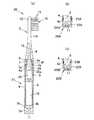
図1(a)に示すように、第1の電動歯ブラシ1は、持ち手としてのハンドル部2に替えブラシ3を着脱自在に取り付けた電動歯ブラシであって、ハンドル部2は、第1端部4aと第2端部4bとを有する金属製筒状の外装ケース4と、第1端部4aを挿通する小端部5a及び第2端部4bに係止される大端部5bとを有し、外装ケース4の第2端部4b側から内装部材5の小端部5aを挿入して、外装ケース4に内装した内装部材5と、第1端部4aから外部へ突出する小端部5aに結合構造6を介して外嵌固定されるとともに、外装ケース4の第1端部4aに係合して、大端部5bとの協働により、内装部材5からの外装ケース4の脱落を規制する規制部材7とを備えている。(First electric toothbrush)
As shown in FIG. 1A, a first electric toothbrush 1 is an electric toothbrush in which a
この電動歯ブラシ1では、替えブラシ3を着脱自在に取付けるための取付軸8が、外装ケース4から外部へ突出するように内装部材5の小端部5aに設けられ、内装部材5の小端部5a側には振動発生手段9が組み付けられ、内装部材5の長さ方向の途中部には振動発生手段9への給電用の電池10が組み付けられ、内装部材5の大端部5bには充電用の誘導コイル11が組み付けられている。なお、誘導コイル11は、磁束が遮断されないように、外装ケース4の外側に配置させることが好ましいが、誘導コイル11を外装ケース4の長さ方向と直交する方向に配置して、外装ケース4のうちの誘導コイル1の両極に対面する部分に切欠部や貫通孔を形成し、充電器からの磁束が遮断されないように構成することも可能である。 In this electric toothbrush 1, an
この電動歯ブラシ1において、外装ケース4に内装部材5を組付ける際には、取付軸8を設けた内装部材5の小端部5aを外装ケース4の第2端部4b側から外装ケース4内に挿入して、外装ケース4内に内装部材5を装填し、外装ケース4の第1端部4aから外部へ突出する内装部材5の小端部5aに、凹凸嵌合や螺合などの結合構造6を介して規制部材7を外嵌固定し、内装部材5の大端部5bの段差部5cと規制部材7の外装ケース4側の当接面7a間に外装ケース4を保持することで、外装ケース4と内装部材5とを一体化することになる。 In the electric toothbrush 1, when the
なお、電動歯ブラシ1では、内装部材5の小端部5a側に取付軸8を設けたが、大端部5b側に取付軸8を設けることも可能である。この場合には、図1(b)に示す電動歯ブラシ1Aのハンドル部2Aのように、替えブラシ3を着脱自在に取付けるための取付軸8を内装部材5Aの大端部5Abに突出状に設け、内装部材5Aの大端部5Ab側に振動発生手段9を組付け、内装部材5Aの長さ方向の途中部に振動発生手段9への給電用の電池10を組み付け、内装部材5Aの小端部5Aaに充電用の誘導コイル11を組み付けることになる。この電動歯ブラシ1Aを組み立てる際には、誘導コイル11が組み付けられる内装部材5Aの小端部5Aaを外装ケース4の第2端部4b側から挿入して、外装ケース4内に内装部材5Aを装填し、外装ケース4の第1端部4aから外部へ突出する内装部材5Aの小端部5Aaに結合構造6を介して規制部材7を外嵌固定することで、内装部材5Aの大端部5Abの段差部5cと規制部材7の外装ケース4側の当接面7a間に外装ケース4を保持することで、外装ケース4と内装部材5Aとを一体化することになる。 In the electric toothbrush 1, the mounting
(第2の電動歯ブラシ)
次に第2の電動歯ブラシ20の外装ケース4と内装部材5との組付構造について説明するが、第1の電動歯ブラシ1と同一部材には同一符号を付してその説明を省略し、第1の電動歯ブラシ1との相違点についてのみ説明する。(Second electric toothbrush)
Next, the assembly structure of the
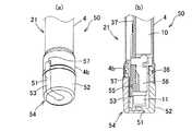
第1の電動歯ブラシ1のハンドル部2では、内装部材5の大端部5bと、内装部材5の小端部5aに固定した規制部材7間に外装ケース4を保持させて、外装ケース4と内装部材5とを一体化させたが、図2(a)に示す第2の電動歯ブラシ20のハンドル部21のように、外装ケース4の第1端部4aに内側へ延びる被保持部4cを形成し、小端部5aに結合構造6を介して規制部材7を固定し、規制部材7と内装部材5の小端部5a側の段差部5f間に被保持部4cを保持することで、外装ケース4と内装部材5とを一体化させることも可能である。 In the
この電動歯ブラシ20において、外装ケース4に内装部材5を組付ける際には、取付軸8を設けた内装部材5の小端部5aを外装ケース4の第2端部4b側から外装ケース4内に挿入して、外装ケース4内に内装部材5を装填し、外装ケース4の第1端部4aから外部へ突出する内装ケースの小端部5aに結合構造6を介して規制部材7を外嵌固定して、小端部5aに固定した規制部材7と内装部材5の小端部5a側の段差部5f間に被保持部4cを保持することで、外装ケース4と内装部材5とを一体化することになる。 In the
なお、外装ケース4の第2端部4bは、図2(a)に示す電動歯ブラシ20のように、前記第1の電動歯ブラシ1と同様に、内装部材5に大端部5bを形成して閉塞したり、図2(b)に示す電動歯ブラシ20Aのように、内装部材5の小端部5aとは反対側の端部5ABを外装ケース4の第2端部4bよりも小径に構成し、別部材からなる蓋部材22Aを外装ケース4の第2端部4bに螺合や凹凸嵌合などの結合構造23Aを介して取付けて、蓋部材22Aにより第2端部4bを閉塞したり、図2(c)に示す電動歯ブラシ20Bのように、内装部材5の小端部5aとは反対側の端部5BBを外装ケース4の第2端部4bよりも小径に構成し、別部材からなる蓋部材22Bを端部5Bbに螺合や凹凸嵌合などの結合構造23Bを介して取付けて、蓋部材22Bにより第2端部4bを閉塞したりすることが可能である。 The
(構成部品)
次に、電動歯ブラシ1、1A、20、20A、20Bの構成部品について説明する。
替えブラシ3は、上端部に植毛台12を形成し、下端部に取付軸8に着脱自在に嵌合する取付孔13を形成した合成樹脂製の柄14と、植毛台12に複数の毛束15を植設してなるブラシ部16とを備えた周知の構成のものである。(Component part)
Next, the components of the
The
外装ケース4としては、電動歯ブラシを極力軽量に構成するため、アルミニウム合金やマグネシウム合金などの軽金属材料で構成することが好ましいが、錆の発生を極力防止するためステンレスなどで構成することも好ましい。また、アルミニウム合金で構成する場合には、外面にアルマイト処理を施して意匠性や耐擦傷性や防錆性を向上することが好ましい。外装ケース4の外径は、手動によるブラッシングの操作性を向上するため、8〜18mm、好ましくは8〜15mm、さらに好ましくは8〜12mmに設定することが好ましい。外装ケース4の肉厚は、使用する金属材料にもよるが、例えばアルミニウム合金で構成する場合には、0.1mm未満の場合には十分な強度剛性が得られず、1.0mmを超えると、外装ケース4の外径が大きくなるとともに、電動歯ブラシが重たくなるので、0.1〜1.0mmに設定することが好ましい。更に、外装ケース4の外周面に滑り止め用の複数のディンプルを設けることも好ましい実施の形態である。更にまた、外装ケース4は、全長にわたって略同径に構成することも可能であるが、電動歯ブラシ1、20、20A、20Bにおいては、取付軸8側へ行くにしたがって縮径するテーパ筒体で構成することも可能である。 The
内装部材5、5Aは、合成樹脂材料で構成され、1部品で構成することも可能であるが、一体的に結合可能な複数部品に分割構成することも可能であり、例えば図4に示すように、大端部5b側と小端部5a側の2つの分割体5U、5Lで構成して、両者を凹凸嵌合などの結合構造40で一体的に結合するように構成することができる。 The
電動歯ブラシ1、1A、20、20A、20Bでは、取付軸8は内装部材5、5Aに一体的に形成したが、図3に示す電動歯ブラシ1Bのように、取付軸8を内装部材5とは別部材で構成して、内装部材5にインサート成形などにより一体化させることも可能である。 In the
また、電動歯ブラシ1、1A、20、20A、20Bでは、振動発生手段9として、モータ25と、モータ25の回転軸25aに固定した錘ムーブメント26とを有し、モータ25により錘ムーブメント26を偏心回転させることで、内装部材5、5Aを振動させ、この振動を取付軸8と柄14を介してブラシ部16に伝達するように構成したものを用いたが、図3に示す電動歯ブラシ1Bのように、内装部材5の長さ方向に往復直線運動する出力軸27aを有するリニアアクチュエータ27と、該リニアアクチュエータ27の出力軸27aの両端部に固定した錘ムーブメント28とを備え、リニアアクチュエータ27により錘ムーブメント28を往復直線運動させて、内装部材5に作用する振動をブラシ部16に伝達するように構成した振動発生手段29を用いることもできる。この振動発生手段29では、バス法によるブラッシング操作を助勢することができる。なお、錘ムーブメント28は出力軸27aの両端部に設けることもできるし、片側にのみ設けることもできる。更に、振動発生手段としては、ハンドル部2を細くスリムに構成するため、振動発生手段9、29のように錘振動タイプを採用することが好ましいが、直線運動タイプ、反転運動タイプ、リニア振動タイプなどの振動発生手段を採用することも可能である。 Further, the electric toothbrushes 1, 1 </ b> A, 20, 20 </ b> A, 20 </ b> B have the
振動発生手段9、28を作動状態と停止状態とに切り換えるためのソフトスイッチが設けられ、このソフトスイッチでは、加速度センサ38(図4(b)参照)からの出力に基づいて、手動によるブラッシング操作を検出した際に、振動発生手段9、28へ通電し、手動によるブラッシング操作が検出されなかったときに、振動発生手段9、28への通電を遮断するように構成されている。ただし、振動発生手段9、28への通電用の機械式の電源スイッチを電動歯ブラシの下端部や側面に設けることも可能である。 A soft switch for switching the vibration generating means 9 and 28 between the operating state and the stopped state is provided. With this soft switch, a manual brushing operation is performed based on the output from the acceleration sensor 38 (see FIG. 4B). When the vibration is detected, the vibration generating means 9 and 28 are energized. When no manual brushing operation is detected, the vibration generating means 9 and 28 are de-energized. However, it is also possible to provide a mechanical power switch for energizing the vibration generating means 9 and 28 on the lower end and the side surface of the electric toothbrush.
電池10としては、ニッケル水素二次電池やリチウムイオン二次電池などの二次電池が用いられ、外部の充電器に電動歯ブラシをセットすることで、誘導コイル11により電池10を充電できるように構成されている。ただし、電池10の充電は、誘導コイル11を用いて非接触により行えるように構成することが、電動歯ブラシの水密性を向上する上で好ましいが、誘導コイル11を省略して、充電器に電動歯ブラシをセットしたときに、電源端子が接触されて充電できるように構成することも可能である。また、二次電池に代えて、一次電池を用いることも可能である。 As the
この第1及び第2の電動歯ブラシによれば、外装ケース4を合成樹脂材料で構成する場合と比較して、ハンドル部2を軽量で、しかも細くスリムに構成することが可能となる。また、振動発生手段9、28に関しても、比較的出力の弱い小型な、例えば錘回転振動タイプや錘リニア振動タイプなどの錘振動タイプの振動発生手段を採用することで、電動によるブラッシング力は低下するものの、電動歯ブラシのハンドル部2をより細くスリムに構成して、手動によるブラッシング操作の操作性を高めることで、電動歯ブラシのブラッシング性能を全体として十分に確保できる。このため、手の小さい子供や女性、握力が弱かったり持続力に乏しい子供や老齢者、病人においても、握り易く、操作し易く、しかもブラッシング性能に優れた電動歯ブラシを実現できる。また、内装部材5の大端部5bや規制部材7の外面を外装ケース4の外面と面一に構成して、外装ケース4の半径方向外方側へ突出しないように構成することで、凹凸の少ないすっきりしたデザインの、意匠性に優れた電動歯ブラシを実現できる。 According to the first and second electric toothbrushes, it is possible to make the
(電動歯ブラシの具体的構成)
次に、第2の電動歯ブラシ20の具体的構成について説明する。なお、本実施の形態では、替えブラシ3を上側にして電動歯ブラシ20を縦向きにした状態を基準に上下を定義して説明する。(Specific configuration of electric toothbrush)
Next, a specific configuration of the second
図4〜図6に示すように、電動歯ブラシ20は、持ち手としてのハンドル部21と、ハンドル部21の取付軸8に着脱自在に取付けた替えブラシ3とを備え、ハンドル部21を細くスリムに構成することで、手動によるブラッシング操作の操作性を向上するとともに、ハンドル部21に組み込んだ振動発生手段9により、替えブラシ3のブラシ部16を振動させて、手動によるブラッシング操作を、電動によるブラッシング操作により助勢できるように構成したものである。 As shown in FIGS. 4 to 6, the
替えブラシ3は、上端部に植毛台12を形成し、下端部に取付軸8に着脱自在に嵌合する取付孔13を形成した合成樹脂製の柄14と、植毛台12に複数の毛束15を植設してなるブラシ部16とを備えた周知の構成のものである。 The
替えブラシ3には取付孔13を構成する弾性変形可能な1対の係止片3aが形成され、取付軸8の途中部には係合溝8aが形成され、替えブラシ3は、係止片3aの下端部に設けた凸部3bと係合溝8aとの係合により、ブラッシング操作程度の力では容易に脱落しないように着脱自在に構成されている。ただし、取付軸8に対する替えブラシ3の取付構造としては、周知の構成のものを採用でき、例えば替えブラシ3の取付孔13に取付軸8を挿入した後、替えブラシ3を一定角度回転させることで、取付軸8に対して替えブラシ3を連結できるように構成することもできる。 The
ハンドル部21は、アルミニウム合金製の円筒状の外装ケース4と、外装ケース4に内装した合成樹脂製の内装部材5とを備えている。外装ケース4の上端部には小径の第1端部4aが形成され、第1端部4aの基部には内側へ延びる鍔状の段差部からなる被保持部4cが形成され、第1端部4aの上端部には内側へ延びる鍔状の規制部4dが形成されている。内装部材5の上端部には第1端部4aに内嵌される円筒状の小端部5aが形成され、内装部材5の下端部には外装ケース4の第2端部4bに係止される大端部5bが形成され、内装部材5は、小端部5aを外装ケース4の下端部から挿入して、外装ケース4に内装され、この状態で、小端部5aに結合構造6を介して筒状の規制部材7を外嵌固定し、規制部材7と内装部材5の小端部5aの基部の段差部5f間に被保持部4cを保持するとともに、規制部材7の当接面7aと大端部5bの段差部5c間に外装ケース4を保持することで、外装ケース4に一体的に組み付けられている。 The
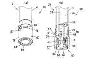
第1端部4aに対する規制部材7の結合構造6について説明すると、規制部材7が、上端側を縮径させた筒状のカバー部7bと、カバー部7bの上端部からカバー部7bの内側へ垂下させた1対の係止爪7cとを備え、係止爪7cの下端部には内側へ突出する係止凸部7dが形成されている。小端部5aは被保持部4cよりも上方へ突出され、小端部5aの高さ方向の途中部には1対の係止凹部5dが形成され、規制部材7は、係止凸部7dが係止凹部5dに凹凸嵌合するように、小端部5aに外嵌させることで、容易には脱落しないように、小端部5aに組み付けられている。なお、符号5eは、小端部5aに設けたハンドル部21の長さ方向に延びる嵌合溝であり、符号7eは、規制部材7に設けた嵌合凸部であり、規制部材7は、嵌合凸部7eが嵌合溝5eに凹凸嵌合することで、小端部5aに相対回転不能に回り止めされている。 The
なお、規制部材7と小端部5aとの結合構造6としては、図7に示す結合構造6Aのように、小端部5aの外周面に係止凹部5dに代えて雄ネジ部30を形成し、規制部材7に代えて、カバー部7bの内周面に雌ネジ部31を形成した規制部材7Aを用い、小端部5aに規制部材7Aを螺合させて、規制部材7Aを小端部5aに固定することも可能である。また、図8に示す結合構造6Bのように、小端部5aの外周面に下向きU字状の1対の係止部32を突出状に形成し、規制部材7に代えて、カバー部7bの内周面に1対の係止凸部33を形成した規制部材7Bを用い、図8(c)に示すように、小端部に規制部材7Bを嵌合させた後、規制部材7Bを矢印Aの方向へ回転させることで、係止凸部33の円弧面33aが係止部32の円弧面32aを乗り越えて、図8(b)に示すように、係止部32の凹部32aに係止凸部33に嵌合することで、係止部32で規制部材7Bを抜け止めできるように構成することも好ましい。 As the
内装部材5は、大端部5b側と小端部5a側の2つの分割体5U、5Lで構成され、両分割体5U、5Lは凹凸嵌合などの結合構造40で一体的に結合されている。内装部材5の小端部5aには替えブラシ3を着脱自在に取付けるための取付軸8がインサート成形により一体的に設けられ、内装部材5の小端部5a側には振動発生手段9が組み付けられ、内装部材5の長さ方向の途中部には振動発生手段9への給電用の電池10が組み付けられ、内装部材5の大端部5bには充電用の誘導コイル11が組み付けられている。 The
内装部材5の小端部5aと外装ケース4の第1端部4a間にはシールリング35が装着され、内装部材5の大端部5bよりもやや上側部分と外装ケース4の下端部間にはシールリング36が装着され、両シールリング35、36により外装ケース4内の水密性が確保されている。 A
内装部材5の上部にはモータ25が取付けられ、内装部材5の途中部には電池10が組み付けられ、内装部材5の側部には回路基板37が取付けられ、内装部材5の下部には誘導コイル11が組み付けられ、モータ25と電池10と回路基板37と誘導コイル11は内装部材5とともに外装ケース4に組み込まれている。 A
振動発生手段9は、モータ25と、モータ25の回転軸25aの上端部に固定した錘ムーブメント26とを有し、モータ25により錘ムーブメント26を偏心回転させることで、外装ケース4の上部を振動させ、この振動を取付軸8と柄14を介してブラシ部16に伝達するように構成されている。なお、符号39は、電池接点である。 The vibration generating means 9 has a
回路基板37には、誘導コイル11から供給される誘導電流により電池10を充電するための充電回路と、ハンドル部21の長さ方向へのハンドル部21の移動を検出する加速度センサ38と、加速度センサ38からの出力を受けて、モータ25への通電を制御するための制御手段などが設けられ、手動によるブラッシング操作が、加速度センサ38により検出されたときに、振動発生手段9を作動させるように構成されている。 On the
この電動歯ブラシ20では、錘振動タイプの振動発生手段9を採用しているので、振動発生手段9を小型に構成できる。また、金属製の外装ケース4を用い、しかも外装ケース4にネジ部を形成しないので、外装ケース4の肉厚を薄くしつつその強度剛性を高めることができ、ハンドル部21を細くスリムに構成できる。このように、ハンドル部21を細くスリムに構成することで、手動によるブラッシングの操作性を高めることができるので、ブラッシング力のあまり強くない錘振動タイプの振動発生手段9を用いつつ、手動によるブラッシングを電動によるブラッシング力で助勢することで、全体として十分なブラッシング性能を確保することが可能となる。 Since the
次に、電動歯ブラシの下部構造を部分的に変更した他の実施の形態について説明する。なお、前記実施の形態と同一部材には同一符号を付してその詳細な説明を省略する。 Next, another embodiment in which the lower structure of the electric toothbrush is partially changed will be described. The same members as those in the above embodiment are denoted by the same reference numerals, and detailed description thereof is omitted.
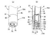
(1)図9に示す下部構造50のように、大端部5bに代えて、L字状の切欠部51を形成した大端部本体52と、切欠部51に嵌合固定した透明部材53とを備えた大端部54を設け、透明部材53に対面するように回路基板37に電動歯ブラシ20や充電器の作動状態を表示するLED55を設け、透明部材53を通じてLED55の発光状態を目視できるように構成することもできる。LED55としては、単色或いは複数色に切換え可能に発光可能なものを採用することができ、電動歯ブラシ20や充電器の状態を利用者に知らせるように構成できる。例えば、緑色と赤色に発光可能な2種類のLEDを設け、二次電池10が十分な充電量を有するときには緑色LEDを点灯し、二次電池10の充電残量が少なくなったときには、緑色LEDを点滅させ、二次電池10が最終放電電圧以下になったときには、緑色LEDを消灯させ、また電動歯ブラシ20を充電器にセットして、二次電池10を充電しているときには、赤色LEDを点灯させ、電動歯ブラシ20を充電器にセットしているにも関わらず、赤色LEDが消灯している場合には、充電器が故障している可能性があることを利用者に知らせることになる。なお、符号56は二次電池10のマイナス極に接続される電池接点である。また符号57は、外装ケース4の下端部に形成した回転止め用の切欠部で、この切欠部57に透明部材53が嵌合することで、外装ケース4と対端部の相対回転が規制される。(1) Like the
(2)図10に示す下部構造60のように、大端部5bに代えて、高さ方向の途中部の外周面に角孔61を形成した大端部本体62と、角孔61に嵌合固定した透明部材63と、底面部に形成した取付孔64と、取付孔64に内嵌装着したシールリング65及び押しボタン66とを備えた大端部67を設け、前記下部構造50と同様に、回路基板37に電動歯ブラシ20や充電器の作動状態を表示するLED55を設けて、透明部材63を通じてLED55の発光状態を目視できるように構成するとともに、回路基板37の下端部に主電源スイッチ68を設け、押しボタン66により操作部材69を介して主電源スイッチ68を操作して、加速度センサ38等への通電を遮断する誤動作防止機能をオン状態とオフ状態とに切換え可能に構成することもできる。この場合には、前記下部構造50と同様の作用効果が得られるとともに、電動歯ブラシ20の出荷後の配送や保管時、或いは利用者が電動歯ブラシ20を携帯して自動車等で移動するときに、押しボタン66を操作して主電源スイッチ68により誤動作防止機能をオン状態にし、加速度センサ38等への通電を遮断することで、電動歯ブラシ20に作用する振動で、電動歯ブラシ20が誤動作することを確実に防止できるとともに、待機電流が発生しないため、電動歯ブラシ20の稼働時間が低下することを防止できる。また、この主電源スイッチ68は、電動歯ブラシ20の使用時に操作する必要が無いことから、従来の電源スイッチとは異なり、電動歯ブラシ20を把持したときに操作できない位置、即ち図10のようにハンドル部21の下端部に設けることができ、主電源スイッチ68を設けることにより、電動歯ブラシ20のハンドル部21が太くなることを防止できる。なお、使用時には、押しボタン66を再度押し操作して主電源スイッチ68により誤動作防止機能をオフ状態にすることで、電動歯ブラシ20を作動状態に切り換えることになる。(2) Like the
(3)図11に示す下部構造70のように、大端部5bに代えて、高さ方向の途中部の外周面に形成した楕円孔71と、楕円孔71に嵌合固定した透明部材72と、底面部に形成した取付孔73と、取付孔73に内嵌装着したシールリング74及び押しボタン75と、底面部に形成したガス抜き穴76とを備えた大端部77を設け、前記下部構造60と同様に、回路基板37に電動歯ブラシ20や充電器の作動状態を表示するLED55を設けて、透明部材72を通じてLED55の発光状態を目視できるように構成するとともに、回路基板37の下端部に主電源スイッチ68を設け、押しボタン75の操作部75aを介して主電源スイッチ68を操作できるように構成し、更にガス抜き穴76における外装ケース4の内側端部に、液体は通過しないが気体は通過する通気性膜79を設け、外部から水などの異物が電動歯ブラシ20の内部に流入することを防止できるように構成することが好ましい。この場合には、下部構造60と同様の作用効果が得られるとともに、二次電池10の劣化に伴いガスが発生した場合でも、該ガスをガス抜き穴76を通じて外部に排出できるので、電動歯ブラシ20が膨張したり、変形したり、破裂したりすることを防止できる。また、図12に示す下部構造70Aのように、楕円孔71に代えて丸孔80を大端部77Aに形成して、該丸孔80に透明部材81を嵌合固定するとともに、押しボタン75に脱落防止用のフック部75bを設けることもできる。(3) As in the
以上、本発明の実施形態について説明したが、本発明は前述した実施形態に何ら限定されるものではなく、本発明の要旨を逸脱しない範囲においてその構成を変更し得ることは勿論である。 The embodiment of the present invention has been described above. However, the present invention is not limited to the above-described embodiment, and it goes without saying that the configuration can be changed without departing from the gist of the present invention.
1 電動歯ブラシ 2 ハンドル部
3 替えブラシ 3a 係止片
3b 凸部
4 外装ケース 4a 第1端部
4b 第2端部 4c 被保持部
4d 規制部
5 内装部材 5a 小端部
5b 大端部 5c 段差部
5d 係止凹部 5e 嵌合溝
5f 段差部
5U 分割体 5L 分割体
6 結合構造 7 規制部材
7a 当接面 7b カバー部
7c 係止爪 7d 係止凸部
7e 嵌合凸部
8 取付軸 8a 係合溝
9 振動発生手段 10 電池
11 誘導コイル 12 植毛台
13 取付孔 14 柄
15 毛束 16 ブラシ部
1A 電動歯ブラシ 2A ハンドル部
5A 内装部材 5Aa 小端部
5Ab 大端部
20 電動歯ブラシ 21 ハンドル部
20A 電動歯ブラシ 22A 蓋部材
23A 結合構造 5AB 端部
20B 電動歯ブラシ 23B 蓋部材
23B 結合構造 5BB 端部
25 モータ 25a 回転軸
26 錘ムーブメント
1B 電動歯ブラシ 27 リニアアクチュエータ
27a 出力軸 28 錘ムーブメント
29 振動発生手段
6A 結合構造 7A 規制部材
30 雄ネジ部 31 雌ネジ部
6B 結合構造 7B 規制部材
32 係止部 32a 円弧面
32b 凹部
33 係止凸部 33a 円弧面
35 シールリング 36 シールリング
37 回路基板 38 加速度センサ
39 電池接点 40 結合構造
50 下部構造 51 切欠部
52 大端部本体 53 透明部材
54 大端部 55 LED
56 電池接点 57 切欠部
60 下部構造 61 角孔
62 大端部本体 63 透明部材
64 取付孔 65 シールリング
66 押しボタン 67 大端部
68 主電源スイッチ 69 操作部材
70 下部構造 70A 下部構造
71 楕円孔 72 透明部材
73 取付孔 74 シールリング
75 押しボタン 75a 操作部
75b フック部 76 ガス抜き穴
77 大端部 77A 大端部
79 通気性膜 80 丸孔
81 透明部材
DESCRIPTION OF SYMBOLS 1
DESCRIPTION OF
25
56
Claims (9)
Translated fromJapanese前記ハンドル部は、
第1端部と第2端部とを有する金属製筒状の外装ケースと、
前記第1端部を挿通する前記第1端部及び第2端部よりも小径の小端部と、前記第2端部に係止される前記第2端部よりも大径の大端部とを有し、前記外装ケースの第2端部側から小端部を挿入して、前記外装ケースに内装した内装部材と、
前記第1端部から外部へ突出する小端部に結合構造を介して外嵌固定されるとともに、前記外装ケースの第1端部に係合して、前記大端部との協働により、前記内装部材からの外装ケースの脱落を規制する規制部材と、
前記替えブラシを振動させるために、前記内装部材に組み込んだ振動発生手段と、
を備えたことを特徴とする電動歯ブラシ。An electric toothbrush with a brush attached detachably to the handle as a handle,
The handle portion is
A metal cylindrical outer case having a first end and a second end;
A small end portion havinga smallerdiameter than the first end portion and the second end portion inserted throughthe first end portion, anda large end portion having alarger diameter than the second end portion locked tothe second end portion An interior member that is inserted into the exterior case by inserting a small end from the second end side of the exterior case, and
While being fitted and fixed to the small end protruding outside from the first end via a coupling structure, by engaging with the first end of the exterior case, in cooperation with the large end, A regulating member that regulates dropping of the outer case from the inner member;
Vibration generating means incorporated in the interior member to vibrate the replacement brush;
An electric toothbrush comprising:
前記ハンドル部は、
第1端部と第2端部とを有し、前記第1端部に内側へ延びる被保持部を形成した金属製の外装ケースと、
前記第1端部を挿通する前記第1端部及び第2端部よりも小径の小端部を有し、前記外装ケースの第2端部側から小端部を挿入して、前記外装ケースに内装した内装部材と、
前記第1端部から外部へ突出する小端部に結合構造を介して外嵌固定されるとともに、前記内装部材との間へ延びる第1端部の被保持部を保持して、前記内装部材からの外装ケースの脱落を規制する規制部材と、
前記替えブラシを振動させるために、前記内装部材に組み込んだ振動発生手段と、
前記替えブラシを着脱自在に取り付けるために、前記小端部に設けた取付軸と、
前記第2端部を閉塞する蓋部材と、
を備えたことを特徴とする電動歯ブラシ。An electric toothbrush with a brush attached detachably to the handle as a handle,
The handle portion is
A metal exterior case having a first end portion and a second end portion and forming a held portion extending inwardly to the first end portion;
The exterior case hasa small end smaller indiameter than the first end and the second end inserted throughthe first end, and a small end is inserted from the second end side of the exterior case. And interior materials
The interior member is fitted and fixed to a small end portion projecting outward from the first end portion via a coupling structure, and holds a held portion of the first end portion extending between the interior member and the interior member. A regulating member that regulates the falling off of the outer case from
Vibration generating means incorporated in the interior member to vibrate the replacement brush;
In order to detachably attach the replacement brush, an attachment shaft provided at the small end,
A lid member for closing the second end;
An electric toothbrush comprising:
Applications Claiming Priority (3)
| Application Number | Priority Date | Filing Date | Title |
|---|---|---|---|
| JP2014068289 | 2014-03-28 | ||
| JP2014068289 | 2014-03-28 | ||
| PCT/JP2015/059118WO2015147054A1 (en) | 2014-03-28 | 2015-03-25 | Electrically driven toothbrush |
Publications (2)
| Publication Number | Publication Date |
|---|---|
| JPWO2015147054A1 JPWO2015147054A1 (en) | 2017-04-13 |
| JP6217843B2true JP6217843B2 (en) | 2017-10-25 |
Family
ID=54195565
Family Applications (1)
| Application Number | Title | Priority Date | Filing Date |
|---|---|---|---|
| JP2016510424AActiveJP6217843B2 (en) | 2014-03-28 | 2015-03-25 | electric toothbrush |
Country Status (5)
| Country | Link |
|---|---|
| EP (1) | EP3123978B1 (en) |
| JP (1) | JP6217843B2 (en) |
| CN (1) | CN106456302B (en) |
| ES (1) | ES2759242T3 (en) |
| WO (1) | WO2015147054A1 (en) |
Cited By (1)
| Publication number | Priority date | Publication date | Assignee | Title |
|---|---|---|---|---|
| US11918101B2 (en) | 2019-04-09 | 2024-03-05 | Shanghai Shift Electrics Co., Ltd. | Connecting structure for electric cleaning device handle and head assembly |
Families Citing this family (7)
| Publication number | Priority date | Publication date | Assignee | Title |
|---|---|---|---|---|
| US9724180B1 (en) | 2017-01-06 | 2017-08-08 | Harria Investment Group Inc. | Brush head for electric toothbrush |
| JP7091697B2 (en)* | 2018-02-20 | 2022-06-28 | サンスター株式会社 | electric toothbrush |
| US11399618B2 (en) | 2018-04-27 | 2022-08-02 | L'oreal | Methods and applicators for applying skin-tightening film products |
| CN108712050A (en)* | 2018-07-26 | 2018-10-26 | 广州薇美姿实业有限公司 | A kind of electric toothbrush with linear vibration electric motor |
| WO2022255857A1 (en)* | 2021-05-31 | 2022-12-08 | Joo Koi Lai | A vibrational oral care apparatus with improved safety feature |
| EP4215154B1 (en)* | 2022-01-20 | 2025-05-28 | The Gillette Company LLC | Handle for an electrically operated personal care implement and electrically operated personal care implement |
| WO2025124054A1 (en)* | 2023-12-11 | 2025-06-19 | 戴晓国 | Electric toothbrush |
Family Cites Families (14)
| Publication number | Priority date | Publication date | Assignee | Title |
|---|---|---|---|---|
| US3060474A (en)* | 1957-02-16 | 1962-10-30 | Aesup Ets | Watertight sealing means for electric toothbrushes and the like |
| EP0622845A3 (en)* | 1993-04-30 | 1995-03-29 | Hewlett Packard Co | Apparatus and method for tape automated bonding beam lead insulation. |
| JP2605005Y2 (en)* | 1993-09-16 | 2000-06-19 | 三洋電機株式会社 | Electrical equipment |
| JP2000175745A (en)* | 1998-12-16 | 2000-06-27 | Akoozu:Kk | Electronic toothbrush |
| JP4674736B2 (en)* | 2000-12-27 | 2011-04-20 | 九州日立マクセル株式会社 | Case body |
| US6920659B2 (en)* | 2001-01-12 | 2005-07-26 | Water Pik, Inc. | Toothbrush |
| JP4306315B2 (en)* | 2003-04-18 | 2009-07-29 | サンスター株式会社 | Grip body with switch |
| JP4998012B2 (en)* | 2006-08-29 | 2012-08-15 | オムロンヘルスケア株式会社 | electric toothbrush |
| JP5266870B2 (en)* | 2008-05-19 | 2013-08-21 | オムロンヘルスケア株式会社 | electric toothbrush |
| CN201299667Y (en)* | 2008-11-28 | 2009-09-02 | 张凌云 | Novel electric toothbrush |
| WO2011041631A2 (en)* | 2009-10-02 | 2011-04-07 | Dentsply International Inc. | Cordless dental handpiece, system including a cordless dental handpiece, and method of connecting a cordless dental handpiece |
| JP2012183219A (en)* | 2011-03-07 | 2012-09-27 | Omron Healthcare Co Ltd | Vibration-generating device and electric toothbrush |
| CN203029417U (en)* | 2012-12-18 | 2013-07-03 | 宁波吉登电子科技有限公司 | Novel electric toothbrush |
| CN203506913U (en)* | 2013-10-31 | 2014-04-02 | 黎泽通 | Electric toothbrush |
- 2015
- 2015-03-25EPEP15769937.2Apatent/EP3123978B1/enactiveActive
- 2015-03-25JPJP2016510424Apatent/JP6217843B2/enactiveActive
- 2015-03-25ESES15769937Tpatent/ES2759242T3/enactiveActive
- 2015-03-25WOPCT/JP2015/059118patent/WO2015147054A1/enactiveApplication Filing
- 2015-03-25CNCN201580022613.8Apatent/CN106456302B/enactiveActive
Cited By (1)
| Publication number | Priority date | Publication date | Assignee | Title |
|---|---|---|---|---|
| US11918101B2 (en) | 2019-04-09 | 2024-03-05 | Shanghai Shift Electrics Co., Ltd. | Connecting structure for electric cleaning device handle and head assembly |
Also Published As
| Publication number | Publication date |
|---|---|
| CN106456302B (en) | 2018-09-28 |
| CN106456302A (en) | 2017-02-22 |
| EP3123978A1 (en) | 2017-02-01 |
| ES2759242T3 (en) | 2020-05-08 |
| EP3123978A4 (en) | 2017-11-22 |
| WO2015147054A1 (en) | 2015-10-01 |
| JPWO2015147054A1 (en) | 2017-04-13 |
| EP3123978B1 (en) | 2019-09-18 |
Similar Documents
| Publication | Publication Date | Title |
|---|---|---|
| JP6217843B2 (en) | electric toothbrush | |
| JP5983860B2 (en) | electric toothbrush | |
| JP7016335B2 (en) | Cleaning device | |
| EP3413834B1 (en) | Electrical toothbrush with rigidly connected grip portion and brush portion | |
| JP6426269B2 (en) | Electric toothbrush with replacement head | |
| JP6703716B2 (en) | electric toothbrush | |
| EP2517667B1 (en) | Electric toothbrush | |
| JP6122839B2 (en) | electric toothbrush | |
| EP2517668B2 (en) | Electric toothbrush | |
| WO2017160811A1 (en) | Electric toothbrush with an illumination ring | |
| KR102116851B1 (en) | Exchangeable electric toothbrush combinded with scaler | |
| EP3156002A1 (en) | Electric toothbrush travel charger speaker case | |
| US20160081779A1 (en) | Solar powered dental hygiene device | |
| US10966807B1 (en) | Electric toothbrushes | |
| JP7091697B2 (en) | electric toothbrush | |
| JP5717258B2 (en) | Electric interdental brush combined with toothbrush | |
| KR20210016366A (en) | Electric toothbrush | |
| JP2005261462A (en) | Electric toothbrush | |
| JP5827824B2 (en) | electric toothbrush | |
| JP3103580U (en) | Ultrasonic operated toothbrush | |
| KR102084434B1 (en) | A slim vibrating toothbrush with integrated toothbrush head | |
| JP2013248015A (en) | Interdental space cleaner, and mobile type oral hygiene device provided with the cleaner | |
| CN201469450U (en) | Electric handle capable of providing toothbrush sleeve joint use | |
| KR20090080026A (en) | Vibrating toothbrush |
Legal Events
| Date | Code | Title | Description |
|---|---|---|---|
| A131 | Notification of reasons for refusal | Free format text:JAPANESE INTERMEDIATE CODE: A131 Effective date:20170627 | |
| A521 | Request for written amendment filed | Free format text:JAPANESE INTERMEDIATE CODE: A523 Effective date:20170817 | |
| TRDD | Decision of grant or rejection written | ||
| A01 | Written decision to grant a patent or to grant a registration (utility model) | Free format text:JAPANESE INTERMEDIATE CODE: A01 Effective date:20170829 | |
| A61 | First payment of annual fees (during grant procedure) | Free format text:JAPANESE INTERMEDIATE CODE: A61 Effective date:20170911 | |
| R150 | Certificate of patent or registration of utility model | Ref document number:6217843 Country of ref document:JP Free format text:JAPANESE INTERMEDIATE CODE: R150 | |
| R250 | Receipt of annual fees | Free format text:JAPANESE INTERMEDIATE CODE: R250 | |
| R250 | Receipt of annual fees | Free format text:JAPANESE INTERMEDIATE CODE: R250 | |
| R250 | Receipt of annual fees | Free format text:JAPANESE INTERMEDIATE CODE: R250 | |
| R250 | Receipt of annual fees | Free format text:JAPANESE INTERMEDIATE CODE: R250 | |
| R250 | Receipt of annual fees | Free format text:JAPANESE INTERMEDIATE CODE: R250 |