JP6208588B2 - Support mechanism and substrate processing apparatus - Google Patents
Support mechanism and substrate processing apparatusDownload PDFInfo
- Publication number
- JP6208588B2 JP6208588B2JP2014013738AJP2014013738AJP6208588B2JP 6208588 B2JP6208588 B2JP 6208588B2JP 2014013738 AJP2014013738 AJP 2014013738AJP 2014013738 AJP2014013738 AJP 2014013738AJP 6208588 B2JP6208588 B2JP 6208588B2
- Authority
- JP
- Japan
- Prior art keywords
- lid
- elastic
- support member
- elastic body
- contact
- Prior art date
- Legal status (The legal status is an assumption and is not a legal conclusion. Google has not performed a legal analysis and makes no representation as to the accuracy of the status listed.)
- Active
Links
Images


Classifications
- F—MECHANICAL ENGINEERING; LIGHTING; HEATING; WEAPONS; BLASTING
- F27—FURNACES; KILNS; OVENS; RETORTS
- F27D—DETAILS OR ACCESSORIES OF FURNACES, KILNS, OVENS OR RETORTS, IN SO FAR AS THEY ARE OF KINDS OCCURRING IN MORE THAN ONE KIND OF FURNACE
- F27D1/00—Casings; Linings; Walls; Roofs
- F27D1/18—Door frames; Doors, lids or removable covers
- F27D1/1808—Removable covers
- F—MECHANICAL ENGINEERING; LIGHTING; HEATING; WEAPONS; BLASTING
- F27—FURNACES; KILNS; OVENS; RETORTS
- F27B—FURNACES, KILNS, OVENS OR RETORTS IN GENERAL; OPEN SINTERING OR LIKE APPARATUS
- F27B17/00—Furnaces of a kind not covered by any of groups F27B1/00 - F27B15/00
- F27B17/0016—Chamber type furnaces
- F27B17/0025—Chamber type furnaces specially adapted for treating semiconductor wafers
Landscapes
- Engineering & Computer Science (AREA)
- Mechanical Engineering (AREA)
- General Engineering & Computer Science (AREA)
- Physics & Mathematics (AREA)
- Condensed Matter Physics & Semiconductors (AREA)
- General Physics & Mathematics (AREA)
- Manufacturing & Machinery (AREA)
- Computer Hardware Design (AREA)
- Microelectronics & Electronic Packaging (AREA)
- Power Engineering (AREA)
- Container, Conveyance, Adherence, Positioning, Of Wafer (AREA)
Description
Translated fromJapanese本発明は、支持機構及び基板処理装置に関する。 The present invention relates to a support mechanism and a substrate processing apparatus.
例えば半導体装置の製造においては、被処理体である基板(例えば半導体ウエハ:以下ウエハ)に対して、成膜処理、酸化処理、拡散処理、アニール処理、エッチング処理等の処理が施される。一般的に、これらの処理は、複数枚のウエハをバッチ式で処理可能な、ヒータ装置を有する縦型の基板処理装置で実施される。 For example, in manufacturing a semiconductor device, a substrate (for example, a semiconductor wafer: hereinafter referred to as a wafer) that is an object to be processed is subjected to processes such as a film formation process, an oxidation process, a diffusion process, an annealing process, and an etching process. In general, these processes are performed by a vertical substrate processing apparatus having a heater apparatus that can process a plurality of wafers in a batch manner.
基板処理装置は、一般的に、前工程から基板処理装置へと搬送される基板を収納する密閉型収納容器(例えば、FOUP)と、処理中にウエハが収納されるウエハボートと、の間でウエハの移載を行うローディングエリアを有する。このローディングエリアの上部空間には、プロセスチューブ(処理容器)及びヒータ装置が設けられており、ウエハが収納されたウエハボートは、昇降機構を介してプロセスチューブ内へと配置される。 In general, a substrate processing apparatus includes a sealed container (for example, FOUP) that stores a substrate transported from a previous process to the substrate processing apparatus, and a wafer boat that stores wafers during processing. A loading area for transferring a wafer is provided. In the upper space of the loading area, a process tube (processing vessel) and a heater device are provided, and a wafer boat storing wafers is arranged in the process tube via an elevating mechanism.
ウエハボートの下方には、一般的に、基板処理中のヒータ装置内の気密を保持するために、プロセスチューブの開口部側に設けられたマニホールドをキャップする蓋体が、ウエハボートと一体的に形成されている。蓋体によりマニホールドをキャップする際には、キャップがマニホールドに対して弾性的に当接することが求められる。また、当接後には、気密保持性の観点から、キャップは所定の密着度を有してマニホールドに密着させる必要がある(例えば、特許文献1参照)。 Below the wafer boat, in general, a lid that caps the manifold provided on the opening side of the process tube is integrated with the wafer boat in order to maintain airtightness in the heater device during substrate processing. Is formed. When the manifold is capped with the lid, the cap is required to elastically contact the manifold. In addition, after the contact, the cap needs to be in close contact with the manifold with a predetermined degree of adhesion from the viewpoint of airtightness retention (see, for example, Patent Document 1).
しかしながら、特許文献1の方法では、蓋体のマニホールドに対する弾性的な当接と、気密保持性とを両立することは困難であった。 However, with the method of
上記課題に対して、蓋体のマニホールドに対する弾性的な当接と、気密保持性とを両立する支持機構を提供する。 In response to the above problems, a support mechanism that achieves both elastic contact of the lid with the manifold and airtightness retention is provided.
昇降手段を用いた昇降により熱処理炉の炉口の封止又は前記封止の解除を行う蓋体を支持する支持機構であって、前記支持機構は、
第1の弾性係数を有する第1の弾性体と、
前記第1の弾性係数よりも弾性係数が大きい第2の弾性係数を有する第2の弾性体と、
前記蓋体に対して下方に離間して設けられ、前記昇降手段の昇降に対応して昇降可能な第2の支持部材と、
前記第2の支持部材に対して下方に離間して設けられ、前記昇降手段の昇降に対応して昇降可能な第3の支持部材と、
前記第2の支持部材と前記第3の支持部材との間に設けられる基部と、前記基部と前記蓋体との間の距離が所定の距離となるように前記基部と前記蓋体とを接続する接続部と、を有する第4の支持部材と、
を有し、
前記第1の弾性体は、一方の端部が前記蓋体に接し、他方の端部が前記第2の支持部材の前記蓋体に対向する第2の面に接し、
前記第2の弾性体は、一方の端部が前記第3の支持部材の前記基部と対向する第3の面に接し、
前記蓋体は、前記昇降手段によって上昇した前記蓋体が前記炉口に当接する際に、前記第1の弾性体に係る反力が印加され、前記昇降手段によって上昇した前記蓋体が前記炉口に当接した後に、前記第1の弾性体及び前記第2の弾性体に係る反力が印加される、支持機構。
A support mechanism that supports a lid that performs sealing of the furnace port of the heat treatment furnace or release of the sealing by elevating using an elevating means, and the support mechanism includes:
A first elastic body having a first elastic modulus;
A second elastic body having a second elastic coefficient having a larger elastic coefficient than the first elastic coefficient;
A second support member which is provided spaced apart downward from the lid and can be raised and lowered in response to the raising and lowering of the raising and lowering means;
A third support member which is provided spaced apart downward with respect to the second support member and can be raised and lowered in response to the raising and lowering of the lifting means;
The base provided between the second support member and the third support member, and the base and the lid are connected so that the distance between the base and the lid is a predetermined distance. A fourth support member having a connecting portion,
Have
The first elastic body has one end in contact with the lid, and the other end in contact with the second surface of the second support member facing the lid,
The second elastic body is in contact with a third surface of which one end portion is opposed to the base portion of the third support member,
The lid is applied with a reaction force on the first elastic body when the lid raised by the elevating means comes into contact with the furnace port, and the lid raised by the elevating means A support mechanism in which a reaction force relating to the first elastic body and the second elastic body is applied after contacting the mouth.
蓋体のマニホールドに対する弾性的な当接と、気密保持性とを両立する支持機構を提供できる。 It is possible to provide a support mechanism that achieves both elastic contact of the lid with the manifold and airtightness.
以下、添付図面を参照して本発明の実施形態について説明する。先ず、本実施形態に係る基板処理装置の一例の全体概略構成について、図1及び図2を用いて説明し、その後、本実施形態に係る蓋体43及び支持機構50近傍の概略構成について、図3乃至図6を参照して説明する。なお、図2においては、説明の容易性の目的で、蓋体43近傍の構成を概略的に示している。 Hereinafter, embodiments of the present invention will be described with reference to the accompanying drawings. First, an overall schematic configuration of an example of a substrate processing apparatus according to the present embodiment will be described with reference to FIGS. 1 and 2, and then a schematic configuration in the vicinity of the
(基板処理装置)
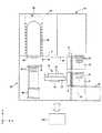
図1に、本実施形態に係る基板処理装置の一例の概略縦断面図を示す。なお、図1においては、説明のために、X軸方向を前後方向の前方向とし、z軸方向を上下方向(又は昇降方向)の上方向として、説明する。また、図2に、本実施形態に係る熱処理炉の一例の概略構成図を示す。(Substrate processing equipment)
FIG. 1 shows a schematic longitudinal sectional view of an example of a substrate processing apparatus according to the present embodiment. In FIG. 1, for the sake of explanation, the X-axis direction is assumed to be the forward direction in the front-rear direction, and the z-axis direction is assumed to be the upward direction in the vertical direction (or the up-down direction). FIG. 2 shows a schematic configuration diagram of an example of a heat treatment furnace according to the present embodiment.
基板処理装置10は、載置台(ロードポート)20、筐体30及び制御部120を有する。 The
載置台20は、筐体30内の前方に設けられ、筐体30内へのウエハWの搬入搬出を行うためのものである。載置台20は、複数枚例えば25枚程度のウエハWを所定の間隔で収納可能な密閉型収納容器(FOUP、基板搬送機器とも称される)21、22が、Z軸方向又はY軸方向に整列して載置可能に構成される。図1に示す例では、密閉型収納容器21、22は、Z軸方向に2つ設けられている例を示している。 The mounting table 20 is provided in front of the
密着型収納容器21、22は、前工程から基板処理装置10の後述するローディングエリア40へとウエハWを搬入する又は基板処理装置10から後工程へとウエハWを搬出するための収納容器であり、前面に図示しない蓋を着脱可能に備える。 The close-contact
また、載置台20の下方には、後述する移載機構47により移載されたウエハWの外周に設けられた切欠部(例えばノッチ)を一方向に揃えるための整列装置(アライナ)23が設けられていても良い。 An alignment device (aligner) 23 for aligning notches (for example, notches) provided on the outer periphery of the wafer W transferred by the
載置台20の後方領域には、作業領域であるローディングエリア40が設けられている。ローディングエリア40は、密閉型収納容器21、22と、後述するウエハボート44との間でウエハWの移載を行う領域である。また、ローディングエリア40の上方には、ウエハボート44に収納されたウエハWに対して、各種熱処理を実施する熱処理炉60が設けられている。なお、ローディングエリア40と熱処理炉60との間には、ベースプレート31が設けられている。 A
前述したように、ローディングエリア40は、密閉型収納容器21、22と、後述するウエハボート44との間でウエハWの移載を行う領域である。ローディングエリア40は、ドア機構41、シャッター機構42、蓋体43、ウエハボート44、移載機構47及び昇降機構48等が設けられている。 As described above, the
ドア機構41は、密閉型収納容器21、22の図示しない蓋を取外して、密閉型収納容器21、22内をローディングエリア40内に連通開放するためのものである。 The door mechanism 41 is for removing the lid (not shown) of the sealed
シャッター機構42は、ローディングエリア40の上方領域であって、ベースプレート31の下方側に設けられている。シャッター機構42は、炉口68から炉内の熱がローディングエリア40に放出されるのを制御するために、蓋体43を開けている(即ち、蓋体43が降下している)場合に炉口68を塞ぐように設けられている。 The shutter mechanism 42 is provided above the
蓋体43は、ウエハボート44の下方側に、ウエハボート44と一体的に設けられている。より具体的には、ウエハボート44の下方側には、ウエハボート44が蓋体43側との伝熱により冷却されることを防止するために、保温筒49が設けられている。そして、保温筒49の下方には、例えばステンレススチールよりなるテーブル92が固定されており、このテーブル92の下方に設けられた軸90の下方に、蓋体43が設けられている。 The
また、蓋体43の下方側には、蓋体43を支持するための支持機構50が設けられいる。蓋体43を支持する支持機構50の詳細については、後述する。なお、蓋体43の上方に載置されているウエハボート44は、処理容器65内でウエハWを水平面内で回転可能に保持することができる。 A
ウエハボート44は、例えば、石英製であり、大口径例えば直径450mm又は300mm等のウエハWを、水平状態で上下方向に所定の間隔で搭載するように構成されている。一般的に、ウエハボート44に収容されるウエハWの枚数は、限定されないが、例えば50〜150枚程度である。なお、図1では、基板処理装置10が、ウエハボート44を1つ有する構成について示したが、複数のウエハボート44を有する構成であっても良い。 The
移載機構47は、密閉型収納容器21、22と、ウエハボート44との間でウエハWの移載を行うためのものである。移載機構47は、基台57、昇降アーム58、及び、複数のフォーク(移載板)59を有する。基台57は、昇降及び旋回可能に設けられている。昇降アーム58は、昇降可能に設けられ、基台57は、昇降アーム58に水平旋回可能に設けられている。 The
昇降機構48は、例えばボートエレベータであり、ウエハWが移載されたウエハボート44を、ローディングエリア40から熱処理炉60に対して搬出入する際において、ウエハボート44(及び蓋体43)を昇降駆動する。昇降機構48は、支持機構50と係合しており、支持機構50を介してウエハボート44及び蓋体43を昇降駆動することができる。そして、昇降機構48によって上昇した蓋体43は、後述するマニホールド84の下端部の開口部に設けられたキャップ部86と当接して、炉口68を密閉するように設けられている。蓋体43とキャップ部86との間には、Oリング等のシール部材94が設けられている。 The elevating
また、ウエハWの各種処理が終了した後は、ウエハボート44をローディングエリア40の下方領域へと下降させる。即ち、昇降機構48は、ウエハボート44を、熱処理炉60内に位置するロード位置(図2のウエハボート44の位置参照)と、熱処理炉60外に位置し、ロード位置の下方に位置するアンロード位置(図1のウエハボート44の位置参照)との間で昇降させることができる。なお、本実施形態に係る蓋体43による炉口68の密閉の詳細については、本実施形態に係る支持機構50の構造と共に、後述する。 In addition, after the various processing of the wafer W is completed, the
熱処理炉60は、複数枚のウエハWを収容して、所定の熱処理を施すためのバッチ型縦型炉であり、処理容器65を備えている。処理容器65は、後述するマニホールド84(図2参照)を介してベースプレート31に支持されている。 The
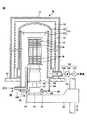
次に、本実施形態に係る基板処理装置10の熱処理炉60部分の詳細な構成例について、図2を参照して説明する。 Next, a detailed configuration example of the
図2に示す例では、縦型の熱処理炉60は、長手方向が垂直である処理容器65と、処理容器65の外周側に処理容器65を囲むように設けられたヒータ装置70と、を有する。 In the example shown in FIG. 2, the vertical
処理容器65は、有天井の外筒80と、この外筒80の内周側に同心的に配置された円筒体の内筒82とを有する、2重管構造で構成される。 The
外筒80及び内筒82は、石英等の耐熱性材料から形成される。また、外筒80及び内筒82は、ステンレススチール等から形成されるマニホールド84によって、その下端部が保持される。 The
マニホールド84の下端部の開口部には、例えばステンレススチール等からなる円環状のキャップ部86が、Oリング等のシール部材88を介して気密防止可能に取り付けられている。この円環状のキャップ部86の中心の開口部が、熱処理炉60の炉口に対応する。 An
熱処理炉60には、処理容器65内に処理ガスを導入するための、ガス導入手段96が設けられる。ガス導入手段96は、マニホールド84を気密に貫通するように設けられたガスノズル100を有する。なお、図2に示す例は、ガス導入手段96が1つ設置される構成を示したが、本発明はこの点において限定されない。使用するガス種の数等に応じて、複数のガス導入手段96を有する構成であっても良い。また、ガスノズル100から処理容器65へと導入されるガスは、図示しない流量制御機構により、流量制御される。 The
また、熱処理炉60には、ガス出口102が設けられており、ガス出口102には、排気系104が連結される。排気系104には、ガス出口102に接続された排気通路106と、排気通路106の途中に順次接続された圧力調整弁108及び真空ポンプ110を含む。排気系104により、処理容器65内の雰囲気を圧力調整しながら排気することができる。 The
処理容器65の外周側には、処理容器65を囲むようにして、ウエハW等の被処理体に熱処理を施すヒータ装置70が設けられる。 On the outer peripheral side of the
ヒータ装置70は、筒体の断熱壁体72を有する。断熱壁体72は、例えば、熱伝導性が低く、柔らかい無定形のシリカ及びアルミナの混合物等から形成することができる。 The heater device 70 has a cylindrical
断熱壁体72は、その内周面が処理容器65の外周面に対して所定の距離離間するように配置される。また、断熱壁体72の外周には、例えば、ステンレススチール等から形成される保護カバー74が、断熱壁体72の外周全体を覆うように取り付けられている。 The
断熱壁体72の内周面側には、ヒータエレメント76が複数回巻回して設けられている。例えば、ヒータエレメント76は、筒体の断熱壁体72の中心軸を軸として、螺旋状に形成されている。 On the inner peripheral surface side of the
また、断熱壁体72には、ヒータエレメント76を所定のピッチで保持するために、図示しない保持部材が、断熱壁体72の軸方向に沿って設けられていても良い。もしくは、断熱壁体72の内周側に、ヒータエレメント76を保持するための溝部が設けられ、この溝部にヒータエレメント76が収容される構成であっても良い。 In addition, a holding member (not shown) may be provided on the
ヒータ装置70は、一般的に、その軸方向においてゾーン分割され、各ゾーン毎に温度制御できる構成になっている。 In general, the heater device 70 is divided into zones in the axial direction, and the temperature can be controlled for each zone.
また、本実施形態に係る基板処理装置10は、制御部120を有する。制御部120は、例えば、演算処理部、記憶部及び表示部を有する。演算処理部は、例えばCPU(Central Processing Unit)を有するコンピュータである。記憶部は、演算処理部に、各種の処理を実行させるためのプログラムを記録した、例えばハードディスクにより構成されるコンピュータ読み取り可能な記録媒体である。表示部は、例えばコンピュータの画面よりなる。演算処理部は、記憶部に記録されたプログラムを読み取り、そのプログラムに従って、基板処理装置を構成する各部に制御信号を送り、各種熱処理を実行する。 Further, the
(第1の実施形態)
次に、本実施形態に係る蓋体43及び支持機構50近傍の実施形態例について、図を参照して説明する。(First embodiment)
Next, an embodiment in the vicinity of the
[従来の支持機構450の問題点]
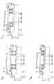
先ず、従来の支持機構450を用いた、蓋体による炉口の封止の問題点について、図3(a)〜図3(c)を参照して説明する。図3(a)〜図3(c)に、従来の支持機構450近傍の概略構成図を示す。図3(a)は、昇降機構48による蓋体43の上昇において、蓋体43がキャップ部86に当接する前の概略図であり、図3(b)は、蓋体43がキャップ部86に当接した直後の概略図であり、図3(c)は、蓋体43が炉口68を十分に封止した状態の概略図である。[Problems of the conventional support mechanism 450]
First, the problem of sealing the furnace port with the lid using the
なお、図3(a)〜図3(c)においては、説明の簡略化のために、マニホールド84のキャップ部86より上方の構成、及び、蓋体43より上方の構成については、省略して示している。 3 (a) to 3 (c), the structure above the
先ず、従来の支持機構450は、図3(a)〜図3(c)に示すように、一方の端部が蓋体43を接するバネ部材等の弾性部材452a、bと、各々の弾性部材452a、bの他方の端部に接する、弾性部材452a、bを支持する支持部材454(キャップベースとも呼ばれる)とを有する。 First, as shown in FIGS. 3A to 3C, the
弾性部材452a、bは、図3(a)〜図3(c)に示す例では、蓋体43に対して2箇所に設けられているが、限定されず、蓋体43の周に沿って例えば3箇所又はそれ以上設けられていても良い。そして、各々の弾性部材452a、bは、弾性係数が同じものが使用される。 In the example shown in FIGS. 3A to 3C, the
支持部材454は、その下方側に搬送機構48が設けられ、支持部材454を介して、蓋体43及び弾性部材452a、bが昇降される。 The
従来の支持機構450においては、蓋体43により炉口68を確実に封止するために、全ての弾性部材452a、bの弾性係数は、シール部材94を十分に潰す押圧力に対応する値に設計される。そのため、図3(a)に示す蓋体43がキャップ部86に当接する前の状態においても、蓋体43には、前記押圧力の反力が印加されている。特に、近年、直径450mm又は300mm等の大口径のウエハが求められており、その要求に対応して、ウエハWの重量も増大している。即ち、蓋体43の上方の負荷(ウエハWが収納されたウエハボート44の重量等)が大きくなっており、それに伴い、蓋体43により炉口68を確実に封止するために、全ての弾性部材452a、bの弾性係数は大きくなっている。 In the
弾性部材452a、bの弾性係数が、炉口68を確実に封止する程度に大きい状態で、蓋体43を更に上昇させて、図3(b)に示すように蓋体43をキャップ部86に当接させた場合、蓋体43を弾性的に(又はソフトタッチで又は緩やかに)キャップ部86に当接することができない。 In a state where the elastic coefficient of the
蓋体43を弾性的にキャップ部86に当接させる案としては、昇降機構48の上昇速度を遅くすることが考えられるが、この場合、スループットが低くなる。また、弾性部材452a、bを支持機構50への組み込み時において、撓み量を少なくすること等も考えられるが、この場合、蓋体43の厚みを大きくする必要があり、装置高さが高くなる。また、蓋体43によるキャップクローズに要する時間が増えるため、スループットが低くなる。 As a proposal for elastically bringing the
なお、従来の支持機構450を使用した場合であっても、図3(c)に示すように、シール部材94を十分に潰すことにより、蓋体43によって炉口68を確実に封止することができる。 Even when the
本発明者らは、従来技術に対する問題点を鋭意検討した結果、第1の弾性係数を有する第1の弾性体と、第1の弾性係数よりも弾性係数が大きい第2の弾性係数を有する第2の弾性体とを含む支持機構を使用し、各々の弾性体からの反力が蓋体に印加されるタイミングを制御することにより、弾性的な当接と、気密保持性とを両立できることを見出した。 As a result of earnestly examining problems with the prior art, the present inventors have found that a first elastic body having a first elastic coefficient and a second elastic coefficient having a second elastic coefficient larger than the first elastic coefficient. 2 using an elastic body and controlling the timing at which the reaction force from each elastic body is applied to the lid body, it is possible to achieve both elastic contact and airtightness. I found it.
即ち、本実施形態に係る支持機構は、
昇降手段を用いた昇降により熱処理炉の炉口の封止又は前記封止の解除を行う蓋体を支持する支持機構であって、前記支持機構は、
第1の弾性係数を有する第1の弾性体と、
前記第1の弾性係数よりも弾性係数が大きい第2の弾性係数を有する第2の弾性体と、
を有し、
前記蓋体は、前記昇降手段によって上昇した前記蓋体が前記炉口に当接する際に、前記第1の弾性体に係る反力が印加され、前記昇降手段によって上昇した前記蓋体が前記炉口に当接した後に、前記第1の弾性体及び前記第2の弾性体に係る反力が印加される。That is, the support mechanism according to this embodiment is
A support mechanism that supports a lid that performs sealing of the furnace port of the heat treatment furnace or release of the sealing by elevating using an elevating means, and the support mechanism includes:
A first elastic body having a first elastic modulus;
A second elastic body having a second elastic coefficient having a larger elastic coefficient than the first elastic coefficient;
Have
The lid is applied with a reaction force on the first elastic body when the lid raised by the elevating means comes into contact with the furnace port, and the lid raised by the elevating means After coming into contact with the mouth, a reaction force is applied to the first elastic body and the second elastic body.
本実施形態に係る支持機構の詳細については、下記に具体的な実施形態を挙げて、図を参照して説明する。 The details of the support mechanism according to the present embodiment will be described with reference to the drawings, citing specific embodiments below.
[第1の実施形態に係る支持機構50aの構成]
第1の実施形態に係る支持機構50aの構成例及び効果について、図4及び図5を参照して説明する。図4に、第1の実施形態に係る支持機構近傍の概略構成図を示す。[Configuration of
A configuration example and effects of the
第1の実施形態に係る支持機構50aは、第1の弾性体と第2の弾性体が、昇降方向において並列に整列され、具体的には、
蓋体43に対して下方に離間して設けられ、前記昇降機構の昇降に対応して昇降可能な第1の支持部材202と、
一方の端部が前記蓋体43に接し、他方の端部が前記第1の支持部材202の前記蓋体43に対向する第1の面202aに接する、第1の弾性係数を有する第1の弾性体204と、
一方の端部が前記第1の支持部材202の第1の面202aに接し、前記第1の弾性係数よりも弾性係数が大きい第2の弾性係数を有する第2の弾性体206と、
を有する。In the
A
A first elastic member having a first elastic coefficient, one end contacting the
A second
Have
そして、前記蓋体43は、前記昇降手段48によって上昇した前記蓋体43が前記炉口68に当接する際に、第1の弾性体204に係る反力が印加され、前記昇降手段48によって上昇した前記蓋体43が前記炉口68に当接した後に、前記第2の弾性体206及び前記第1の弾性体204に係る反力が印加される。 Then, when the
なお、「前記昇降手段48によって上昇した前記蓋体43が前記炉口68に当接した後に、前記第2の弾性体206に係る反力が印加される」とは、「蓋体43が前記炉口68に当接する際(又はその前)には、例えば図4のクリアランスD1により、蓋体43に第2の弾性体206に係る反力が印加されないことを意味する。 Note that “the reaction force applied to the second
第1の実施形態に係る支持機構50aの効果について、図5(a)〜図5(c)を参照して説明する。図5(a)〜図5(c)に、第1の実施形態に係る支持機構50aの効果の一例を説明するための概略図を示す。図5(a)は、昇降機構48による蓋体43の上昇において、蓋体43がキャップ部86に当接する前の概略図であり、図5(b)は、蓋体43がキャップ部86に当接した後であって、第2の弾性体206が蓋体43に当接する直前の概略図であり、図5(c)は、蓋体43が炉口68を十分に封止した状態の概略図である。 The effect of the
なお、図5(a)〜(c)では、図4に示す第1の弾性体204及び第2の弾性体206が、蓋体43の周方向に沿って2つずつ配置される例について示し、各々、第1の弾性体204a、b、第2の弾性体206a、bと示す。しかしながら、本発明はこの点において限定されず、図4に示す第1の弾性体204、第2の弾性体206は、蓋体43の周方向に沿って3つ以上、例えば6つずつ配置されても良い。 5A to 5C show an example in which the first
図5(a)に示すように、蓋体43が炉口68を封止していない場合には、第2の弾性体206a、bは、蓋体43に対して離間している(クリアランスD1参照)。即ち、第2の弾性体206a、bは、蓋体43と接していない。そのため、図5(a)に示す状態では、蓋体43には、第1の弾性体204a、bに対応する反力が印加されるが、第2の弾性体206a、bに対応する反力は印加されていない。 As shown in FIG. 5A, when the
この図5(a)に示す状態から、昇降機構48により第1の支持部材202及び蓋体43を上昇させると、第1の弾性体204a、bのみの弾性係数に対応して、蓋体43がキャップ部86に当接される。そのため、本実施形態に係る支持機構50aにより、蓋体43を、弾性的に(又はソフトタッチで又は緩やかに)キャップ部86へと当接することができる。 When the
蓋体43がキャップ部86に当接した状態で、昇降機構48により更に第1の支持部材202を上昇させると、この上昇幅に対応して、第1の弾性体204a、bが撓む。そして、第1の支持部材202が、クリアランスD1と等しい上昇幅で上昇した段階で、図5(b)に示すように、第2の弾性体206a、bが、蓋体43に接する。 When the
この図5(b)に示す状態から、昇降機構48により更に支持機構50aを上昇させると、蓋体43には、第1の弾性係数及び第2の弾性係数の和に対応する反力が印加される。その結果、シール部材94を十分に潰すことができ、蓋体43によって炉口68を気密性良く封止することができる。 When the
第1の弾性体204a、bの第1の弾性係数としては、蓋体43(及びシール部材94)を、弾性的に(又はソフトタッチで又は緩やかに)キャップ部86へと当接することができれば、シール部材94の材料や昇降機構48による昇降速度に応じて当業者が選択することができる。具体的には、例えば、蓋体43上の負荷が30〜300kgfの範囲内である場合、35〜400kgf/cm2の範囲内とすることができる。As the first elastic coefficient of the first
また、第2の弾性体206a、bの第2の弾性係数は、第1の弾性体204a、bの第1の弾性係数との和が、シール部材94を十分に潰すことができる値であれば、特に制限はなく、シール部材94の材料や昇降機構48による昇降速度に応じて当業者が選択することができる。具体的には、例えば、蓋体43上の負荷が100〜1500kgfの範囲内である場合、例えば、150〜2000kgf/cm2の範囲内とすることができる。In addition, the second elastic coefficient of the second
また、第1の弾性係数に対する第2の弾性係数の比の値としては、好ましくは、2〜5の範囲内、より好ましくは2〜10の範囲内、さらに好ましくは2〜20の範囲内である。 Further, the value of the ratio of the second elastic modulus to the first elastic modulus is preferably in the range of 2 to 5, more preferably in the range of 2 to 10, and further preferably in the range of 2 to 20. is there.
また、第1の弾性体204a、b及び第2の弾性体206a、bは、好ましくはコイル状のバネ部材を使用することが好ましい。 The first
クリアランスD1としては、特に制限はなく、例えば1〜20mmの範囲内とすることができる。 There is no restriction | limiting in particular as clearance D1, For example, it can be in the range of 1-20 mm.
本実施形態に係る支持機構50aは、図4に示すように、軸208及びブッシュガイド210を有することが好ましい。 The
軸208は、第1の弾性体204a、b及び第2の弾性体206a、bの、軸直角方向への伸縮を抑制又は低減し、軸方向への伸縮をガイドする部材である。 The
好ましくは、コイル状のバネ部材の第1の弾性体204a、bの各々の内周側に、コイル状のバネ部材の第2の弾性体206a、bが配置され、第2の弾性体206a、bの各々の内周側に、軸208が配置される。 Preferably, the second
また、ブッシュガイド210は、軸208の外周側に、軸208と接して配置される部材であり、軸208の軸方向長さよりも短く構成される。これにより、軸208の軸方向長さと、ブッシュガイド210の前記軸方向長さの差が、第1の弾性体204a、b及び第2の弾性体206a、bの、最大収縮量となる。 The
以上、第1の実施形態に係る支持機構50aは、蓋体43をキャップ部86へと弾性的に当接させるための第1の弾性体204と、蓋体43をキャップ部86へと気密的に封止するための第2の弾性体206とを有する。これにより、蓋体43のマニホールドに対する弾性的な当接と、気密保持性とを両立することができる。 As described above, the
(第2の実施形態)
次に、第2の実施形態に係る支持機構50bについて、図6(a)〜図6(d)を参照して説明する。図6(a)〜図6(d)に、第2の実施形態に係る支持機構50bの効果の一例を説明するための概略図を示す。なお、図6(a)〜図6(d)においては、支持機構50bにおける必須の構成以外の構成要素については、省略して示している。(Second Embodiment)
Next, a
第2の実施形態に係る支持機構50bは、弾性係数が異なる2種類の弾性体が、昇降方向に直列に配置される点で、第1の実施形態とは異なる。 The
より具体的には、第2の実施形態に係る支持機構50bは、
蓋体43に対して下方に離間して設けられ、前記昇降機構48の昇降に対応して昇降可能な第2の支持部材302と、
前記第2の支持部材302に対して下方に離間して設けられ、前記昇降機構48の昇降に対応して昇降可能な第3の支持部材304と、
前記第2の支持部材302と前記第3の支持部材304との間に設けられる基部306aと、前記基部306aと前記蓋体43との間の距離が所定の距離となるように前記基部306aと前記蓋体43とを接続する接続部306bとを有する、第4の支持部材306と、
一方の端部が前記蓋体43に接し、他方の端部が前記第2の支持部材302の前記蓋体に対向する第2の面302aに接する、第3の弾性係数を有する第3の弾性体308a、bと、
一方の端部が前記第3の支持部材304の前記基部306aと対向する第3の面304aに接し、前記第3の弾性係数よりも弾性係数が大きい第4の弾性係数を有する第4の弾性体310と、
を有する。More specifically, the
A
A
A
A third elasticity having a third elastic coefficient, one end contacting the
A fourth elasticity having a fourth elastic coefficient whose one end is in contact with the
Have
そして、前記蓋体43は、前記昇降手段48によって上昇した前記蓋体43が前記炉口68に当接する際に、第3の弾性体308a、bに係る反力が印加され、前記昇降手段48によって上昇した前記蓋体43が前記炉口68に当接した後に、前記第4の弾性体310a、b及び前記第3の弾性体308a、bに係る反力が印加される。 The
第2の実施形態に係る支持機構50bの効果について、改めて図6(a)〜図6(d)を参照して説明する。図6(a)は、昇降機構48による蓋体43の上昇において、蓋体43がキャップ部86に当接する前の概略図であり、図6(b)は、蓋体43がキャップ部86に当接する直前(又は直後)の概略図であり、図6(c)は、蓋体43がキャップ部86に当接した後であって、第4の弾性体310が第2の支持部材302に当接する直前の概略図であり、図6(d)は、蓋体43が炉口68を十分に封止した状態の概略図である。 The effect of the
図6(a)に示すように、蓋体43が炉口68を封止していない場合には、第4の弾性体310a、bは、基部306aに対して離間している(所定のクリアランスD2を有している)。一方、第3の弾性体308a、bは、蓋体43に直接接している。そのため、図6(a)に示す状態では、蓋体43には、第3の弾性体308a、bに係る反力のみが印加される。別の言い方をすると、図6(a)に示す状態では、蓋体43には、第4の弾性体310a、bに係る反力は印加されていない。 As shown in FIG. 6A, when the
この図6(a)に示す状態から、昇降機構48により蓋体43、第2の支持部材302及び第3の支持部材304を上昇させて図6(b)に示すように蓋体43がキャップ部86に当接させる。この図6(b)に示す状態では、第1の実施形態と同様に、蓋体43には、第3の弾性体308a、bに係る反力のみが印加される。そのため、蓋体43のシール部材94を介したキャップ部86への当接は、弾性的に(又はソフトタッチで又は緩やかに)実施される。即ち、本実施形態に係る支持機構50bにより、蓋体43を、弾性的に(又はソフトタッチで又は緩やかに)キャップ部86へと当接することができる。 From the state shown in FIG. 6A, the
図6(b)に示す蓋体43がキャップ部86に当接した状態で、昇降機構48により更に第2の支持部材302及び第3の支持部材304を上昇させる(蓋体43は、シール部材94の潰れ量に対応する分だけ上昇する)。第2の支持部材302の上昇によって、この上昇量に対応して、第3の弾性体308a、bが撓み、そして、第3の支持部材304の上昇によって、この上昇量に対応して、第4の弾性体310a、bの上端が基部306aへと近づく。なお、第4の支持部材306の基部306aと、蓋体43との間の距離は、接続部306bの長さに対応して、常に一定の距離に維持されている。
6B, the
そして、図6(c)に示すように、第2の支持部材302及び第3の支持部材304の前記上昇量が、クリアランスD2の長さに達した時点で、第4の弾性体310a、bが基部306aに当接する。これにより、蓋体43には、第3の弾性体308a、b及び第4の弾性体310a、bの両方に係る反力が印加される。なお、図6(c)には、説明のために、図6(b)における第2の支持部材302及び第3の支持部材304の位置を、破線で示している。 Then, as shown in FIG. 6C, when the rising amounts of the
図6(c)で示した第4の弾性体310a、bが基部306aへと当接した後、更に、第2の支持部材302及び第3の支持部材304を、例えば幅D3(図6(d))だけ上昇させる。その結果、シール部材94を、第3の弾性体308a、b及び第4の弾性体310a、bの両方に係る反力によって、十分に潰すことができる、即ち、蓋体43によって炉口68を気密性良く封止することができる。なお、図6(d)には、説明のために、図6(c)における第2の支持部材302及び第3の支持部材304の位置を、破線で示している。 After the fourth
なお、第3の弾性体308a、bの第3の弾性係数に関する好ましい範囲は、第1の実施形態の第1の弾性体204a、bの第1の弾性係数と同様である。また、第4の弾性体310a、bの第4の弾性係数に関する好ましい範囲は、第1の実施形態の第2の弾性体206a、bの第2の弾性係数と同様である。 In addition, the preferable range regarding the third elastic coefficient of the third
また、第2の実施形態に係る支持機構50bにおいても、図示しない軸及びブッシュガイドを配置する構成であっても良い。 Further, the
クリアランスD2としては、特に制限はなく、クリアランスD1と同様に、例えば1〜20mmの範囲内とすることができる。 There is no restriction | limiting in particular as clearance D2, It can be in the range of 1-20 mm like the clearance D1, for example.
さらに、図6においては、第3の弾性体308a、b及び第4の弾性体310a、bに示されるように、第3の弾性体及び第4の弾性体が、各々、蓋体43の周方向に沿って2つずつ配置される例について示したが、本発明はこの点において限定されず、例えば、蓋体43の周方向に沿って、3つ以上ずつ、例えば6つずつ配置される構成であっても良い。 Further, in FIG. 6, as shown by the third
以上、第2の実施形態に係る支持機構50bは、蓋体43をキャップ部86へと弾性的に当接させるための第1の弾性体204と、蓋体43をキャップ部86へと気密的に封止するための第2の弾性体206とを有する。これにより、蓋体43のマニホールドに対する弾性的な当接と、気密保持性とを両立することができる。 As described above, the
10 基板処理装置
20 載置台
30 筐体
31 ベースプレート
40 ローディングエリア
43 蓋体
44 ウエハボート
47 移載機構
48 昇降機構
48 搬送機構
49 保温筒
50 支持機構
58 昇降アーム
60 熱処理炉
65 処理容器
68 炉口
70 ヒータ装置
84 マニホールド
86 キャップ部
88 シール部材
90 軸
92 テーブル
94 シール部材
120 制御部
202 第1の支持部材
204 第1の弾性体
206 第2の弾性体
208 軸
210 ブッシュガイド
302 第2の支持部材
304 第3の支持部材
306 第4の支持部材
308 第3の弾性体
310 第4の弾性体DESCRIPTION OF
Claims (4)
Translated fromJapanese第1の弾性係数を有する第1の弾性体と、
前記第1の弾性係数よりも弾性係数が大きい第2の弾性係数を有する第2の弾性体と、
前記蓋体に対して下方に離間して設けられ、前記昇降手段の昇降に対応して昇降可能な第2の支持部材と、
前記第2の支持部材に対して下方に離間して設けられ、前記昇降手段の昇降に対応して昇降可能な第3の支持部材と、
前記第2の支持部材と前記第3の支持部材との間に設けられる基部と、前記基部と前記蓋体との間の距離が所定の距離となるように前記基部と前記蓋体とを接続する接続部と、を有する第4の支持部材と、
を有し、
前記第1の弾性体は、一方の端部が前記蓋体に接し、他方の端部が前記第2の支持部材の前記蓋体に対向する第2の面に接し、
前記第2の弾性体は、一方の端部が前記第3の支持部材の前記基部と対向する第3の面に接し、
前記蓋体は、前記昇降手段によって上昇した前記蓋体が前記炉口に当接する際に、前記第1の弾性体に係る反力が印加され、前記昇降手段によって上昇した前記蓋体が前記炉口に当接した後に、前記第1の弾性体及び前記第2の弾性体に係る反力が印加される、支持機構。A support mechanism that supports a lid that performs sealing of the furnace port of the heat treatment furnace or release of the sealing by elevating using an elevating means, and the support mechanism includes:
A first elastic body having a first elastic modulus;
A second elastic body having a second elastic coefficient having a larger elastic coefficient than the first elastic coefficient;
A second support member which is provided spaced apart downward from the lid and can be raised and lowered in response to the raising and lowering of the raising and lowering means;
A third support member which is provided spaced apart downward with respect to the second support member and can be raised and lowered in response to the raising and lowering of the lifting means;
The base provided between the second support member and the third support member, and the base and the lid are connected so that the distance between the base and the lid is a predetermined distance. A fourth support member having a connecting portion,
Have
The first elastic body has one end in contact with the lid, and the other end in contact with the second surface of the second support member facing the lid,
The second elastic body is in contact with a third surface of which one end portion is opposed to the base portion of the third support member,
The lid is applied with a reaction force on the first elastic body when the lid raised by the elevating means comes into contact with the furnace port, and the lid raised by the elevating means A support mechanism in which a reaction force relating to the first elastic body and the second elastic body is applied after contacting the mouth.
前記第2の弾性係数は、100〜1500kgf/cm2の範囲内である、
請求項1に記載の支持機構。The first elastic modulus is in the range of 35 to 400 kgf / cm2 ;
The second elastic modulus is in a range of 100-1500 kgf / cm2 .
The support mechanism according to claim1 .
請求項1に記載の支持機構。The ratio of the second elastic modulusto the first elastic modulus is in the range of 2-20.
The support mechanism according to claim1 .
前記熱処理炉の炉口の封止又は前記封止の解除を行う蓋体と、
前記蓋体を支持する支持機構と
前記支持機構を介して前記蓋体を昇降する昇降手段と、
を有し、
前記支持機構は、
第1の弾性係数を有する第1の弾性体と、
前記第1の弾性係数よりも弾性係数が大きい第2の弾性係数を有する第2の弾性体と、
前記蓋体に対して下方に離間して設けられ、前記昇降手段の昇降に対応して昇降可能な第2の支持部材と、
前記第2の支持部材に対して下方に離間して設けられ、前記昇降手段の昇降に対応して昇降可能な第3の支持部材と、
前記第2の支持部材と前記第3の支持部材との間に設けられる基部と、前記基部と前記蓋体との間の距離が所定の距離となるように前記基部と前記蓋体とを接続する接続部と、を有する第4の支持部材と、
を有し、
前記第1の弾性体は、一方の端部が前記蓋体に接し、他方の端部が前記第2の支持部材の前記蓋体に対向する第2の面に接し、
前記第2の弾性体は、一方の端部が前記第3の支持部材の前記基部と対向する第3の面に接し、
前記蓋体は、前記昇降手段によって上昇した前記蓋体が前記炉口に当接する際に、前記第1の弾性体に係る反力が印加され、前記昇降手段によって上昇した前記蓋体が前記炉口に当接した後に、前記第1の弾性体及び前記第2の弾性体に係る反力が印加される、支持機構と、
を有する基板処理装置。A heat treatment furnace;
A lid for sealing the furnace port of the heat treatment furnace or releasing the sealing;
A support mechanism for supporting the lid, and an elevating means for raising and lowering the lid via the support mechanism;
Have
The support mechanism is
A first elastic body having a first elastic modulus;
A second elastic body having a second elastic coefficient having a larger elastic coefficient than the first elastic coefficient;
A second support member which is provided spaced apart downward from the lid and can be raised and lowered in response to the raising and lowering of the raising and lowering means;
A third support member which is provided spaced apart downward with respect to the second support member and can be raised and lowered in response to the raising and lowering of the lifting means;
The base provided between the second support member and the third support member, and the base and the lid are connected so that the distance between the base and the lid is a predetermined distance. A fourth support member having a connecting portion,
Have
The first elastic body has one end in contact with the lid, and the other end in contact with the second surface of the second support member facing the lid,
The second elastic body is in contact with a third surface of which one end portion is opposed to the base portion of the third support member,
The lid is applied with a reaction force on the first elastic body when the lid raised by the elevating means comes into contact with the furnace port, and the lid raised by the elevating means A support mechanism to which a reaction force relating to the first elastic body and the second elastic body is applied after contacting the mouth;
A substrate processing apparatus.
Priority Applications (4)
| Application Number | Priority Date | Filing Date | Title |
|---|---|---|---|
| JP2014013738AJP6208588B2 (en) | 2014-01-28 | 2014-01-28 | Support mechanism and substrate processing apparatus |
| TW104102445ATWI598984B (en) | 2014-01-28 | 2015-01-26 | Support mechanism and substrate processing apparatus |
| US14/604,866US9803926B2 (en) | 2014-01-28 | 2015-01-26 | Support mechanism and substrate processing apparatus |
| KR1020150012998AKR101874673B1 (en) | 2014-01-28 | 2015-01-27 | Support mechanism and substrate processing apparatus |
Applications Claiming Priority (1)
| Application Number | Priority Date | Filing Date | Title |
|---|---|---|---|
| JP2014013738AJP6208588B2 (en) | 2014-01-28 | 2014-01-28 | Support mechanism and substrate processing apparatus |
Publications (2)
| Publication Number | Publication Date |
|---|---|
| JP2015141994A JP2015141994A (en) | 2015-08-03 |
| JP6208588B2true JP6208588B2 (en) | 2017-10-04 |
Family
ID=53678703
Family Applications (1)
| Application Number | Title | Priority Date | Filing Date |
|---|---|---|---|
| JP2014013738AActiveJP6208588B2 (en) | 2014-01-28 | 2014-01-28 | Support mechanism and substrate processing apparatus |
Country Status (4)
| Country | Link |
|---|---|
| US (1) | US9803926B2 (en) |
| JP (1) | JP6208588B2 (en) |
| KR (1) | KR101874673B1 (en) |
| TW (1) | TWI598984B (en) |
Cited By (1)
| Publication number | Priority date | Publication date | Assignee | Title |
|---|---|---|---|---|
| KR102652784B1 (en) | 2019-02-20 | 2024-03-28 | 가부시키가이샤 코쿠사이 엘렉트릭 | Substrate processing apparatus, furnace opening closing unit and method of manufacturing semiconductor device |
Families Citing this family (229)
| Publication number | Priority date | Publication date | Assignee | Title |
|---|---|---|---|---|
| US20130023129A1 (en) | 2011-07-20 | 2013-01-24 | Asm America, Inc. | Pressure transmitter for a semiconductor processing environment |
| US20160376700A1 (en) | 2013-02-01 | 2016-12-29 | Asm Ip Holding B.V. | System for treatment of deposition reactor |
| US10941490B2 (en) | 2014-10-07 | 2021-03-09 | Asm Ip Holding B.V. | Multiple temperature range susceptor, assembly, reactor and system including the susceptor, and methods of using the same |
| US10276355B2 (en) | 2015-03-12 | 2019-04-30 | Asm Ip Holding B.V. | Multi-zone reactor, system including the reactor, and method of using the same |
| US11139308B2 (en) | 2015-12-29 | 2021-10-05 | Asm Ip Holding B.V. | Atomic layer deposition of III-V compounds to form V-NAND devices |
| US10529554B2 (en) | 2016-02-19 | 2020-01-07 | Asm Ip Holding B.V. | Method for forming silicon nitride film selectively on sidewalls or flat surfaces of trenches |
| US10343920B2 (en) | 2016-03-18 | 2019-07-09 | Asm Ip Holding B.V. | Aligned carbon nanotubes |
| US11453943B2 (en) | 2016-05-25 | 2022-09-27 | Asm Ip Holding B.V. | Method for forming carbon-containing silicon/metal oxide or nitride film by ALD using silicon precursor and hydrocarbon precursor |
| US9859151B1 (en) | 2016-07-08 | 2018-01-02 | Asm Ip Holding B.V. | Selective film deposition method to form air gaps |
| US10612137B2 (en) | 2016-07-08 | 2020-04-07 | Asm Ip Holdings B.V. | Organic reactants for atomic layer deposition |
| US9887082B1 (en) | 2016-07-28 | 2018-02-06 | Asm Ip Holding B.V. | Method and apparatus for filling a gap |
| US9812320B1 (en) | 2016-07-28 | 2017-11-07 | Asm Ip Holding B.V. | Method and apparatus for filling a gap |
| CN205980793U (en)* | 2016-08-12 | 2017-02-22 | 深圳市捷佳伟创新能源装备股份有限公司 | Low pressure diffusion furnace furnace gate sealing device |
| US11532757B2 (en) | 2016-10-27 | 2022-12-20 | Asm Ip Holding B.V. | Deposition of charge trapping layers |
| US10714350B2 (en) | 2016-11-01 | 2020-07-14 | ASM IP Holdings, B.V. | Methods for forming a transition metal niobium nitride film on a substrate by atomic layer deposition and related semiconductor device structures |
| KR102546317B1 (en) | 2016-11-15 | 2023-06-21 | 에이에스엠 아이피 홀딩 비.브이. | Gas supply unit and substrate processing apparatus including the same |
| US11447861B2 (en) | 2016-12-15 | 2022-09-20 | Asm Ip Holding B.V. | Sequential infiltration synthesis apparatus and a method of forming a patterned structure |
| US11581186B2 (en) | 2016-12-15 | 2023-02-14 | Asm Ip Holding B.V. | Sequential infiltration synthesis apparatus |
| US11390950B2 (en) | 2017-01-10 | 2022-07-19 | Asm Ip Holding B.V. | Reactor system and method to reduce residue buildup during a film deposition process |
| US10468261B2 (en) | 2017-02-15 | 2019-11-05 | Asm Ip Holding B.V. | Methods for forming a metallic film on a substrate by cyclical deposition and related semiconductor device structures |
| US10770286B2 (en) | 2017-05-08 | 2020-09-08 | Asm Ip Holdings B.V. | Methods for selectively forming a silicon nitride film on a substrate and related semiconductor device structures |
| US12040200B2 (en) | 2017-06-20 | 2024-07-16 | Asm Ip Holding B.V. | Semiconductor processing apparatus and methods for calibrating a semiconductor processing apparatus |
| US11306395B2 (en) | 2017-06-28 | 2022-04-19 | Asm Ip Holding B.V. | Methods for depositing a transition metal nitride film on a substrate by atomic layer deposition and related deposition apparatus |
| KR20190009245A (en) | 2017-07-18 | 2019-01-28 | 에이에스엠 아이피 홀딩 비.브이. | Methods for forming a semiconductor device structure and related semiconductor device structures |
| US11374112B2 (en) | 2017-07-19 | 2022-06-28 | Asm Ip Holding B.V. | Method for depositing a group IV semiconductor and related semiconductor device structures |
| US10590535B2 (en) | 2017-07-26 | 2020-03-17 | Asm Ip Holdings B.V. | Chemical treatment, deposition and/or infiltration apparatus and method for using the same |
| TWI815813B (en) | 2017-08-04 | 2023-09-21 | 荷蘭商Asm智慧財產控股公司 | Showerhead assembly for distributing a gas within a reaction chamber |
| US10770336B2 (en) | 2017-08-08 | 2020-09-08 | Asm Ip Holding B.V. | Substrate lift mechanism and reactor including same |
| US10692741B2 (en) | 2017-08-08 | 2020-06-23 | Asm Ip Holdings B.V. | Radiation shield |
| US11769682B2 (en) | 2017-08-09 | 2023-09-26 | Asm Ip Holding B.V. | Storage apparatus for storing cassettes for substrates and processing apparatus equipped therewith |
| US11830730B2 (en) | 2017-08-29 | 2023-11-28 | Asm Ip Holding B.V. | Layer forming method and apparatus |
| US11295980B2 (en) | 2017-08-30 | 2022-04-05 | Asm Ip Holding B.V. | Methods for depositing a molybdenum metal film over a dielectric surface of a substrate by a cyclical deposition process and related semiconductor device structures |
| US10658205B2 (en) | 2017-09-28 | 2020-05-19 | Asm Ip Holdings B.V. | Chemical dispensing apparatus and methods for dispensing a chemical to a reaction chamber |
| US10403504B2 (en) | 2017-10-05 | 2019-09-03 | Asm Ip Holding B.V. | Method for selectively depositing a metallic film on a substrate |
| US10923344B2 (en) | 2017-10-30 | 2021-02-16 | Asm Ip Holding B.V. | Methods for forming a semiconductor structure and related semiconductor structures |
| WO2019103613A1 (en) | 2017-11-27 | 2019-05-31 | Asm Ip Holding B.V. | A storage device for storing wafer cassettes for use with a batch furnace |
| CN111344522B (en) | 2017-11-27 | 2022-04-12 | 阿斯莫Ip控股公司 | Including clean mini-environment device |
| US10872771B2 (en) | 2018-01-16 | 2020-12-22 | Asm Ip Holding B. V. | Method for depositing a material film on a substrate within a reaction chamber by a cyclical deposition process and related device structures |
| KR102695659B1 (en) | 2018-01-19 | 2024-08-14 | 에이에스엠 아이피 홀딩 비.브이. | Method for depositing a gap filling layer by plasma assisted deposition |
| TWI799494B (en) | 2018-01-19 | 2023-04-21 | 荷蘭商Asm 智慧財產控股公司 | Deposition method |
| US11081345B2 (en) | 2018-02-06 | 2021-08-03 | Asm Ip Holding B.V. | Method of post-deposition treatment for silicon oxide film |
| US10896820B2 (en) | 2018-02-14 | 2021-01-19 | Asm Ip Holding B.V. | Method for depositing a ruthenium-containing film on a substrate by a cyclical deposition process |
| WO2019158960A1 (en) | 2018-02-14 | 2019-08-22 | Asm Ip Holding B.V. | A method for depositing a ruthenium-containing film on a substrate by a cyclical deposition process |
| US10731249B2 (en) | 2018-02-15 | 2020-08-04 | Asm Ip Holding B.V. | Method of forming a transition metal containing film on a substrate by a cyclical deposition process, a method for supplying a transition metal halide compound to a reaction chamber, and related vapor deposition apparatus |
| KR102636427B1 (en) | 2018-02-20 | 2024-02-13 | 에이에스엠 아이피 홀딩 비.브이. | Substrate processing method and apparatus |
| US10975470B2 (en) | 2018-02-23 | 2021-04-13 | Asm Ip Holding B.V. | Apparatus for detecting or monitoring for a chemical precursor in a high temperature environment |
| US11473195B2 (en) | 2018-03-01 | 2022-10-18 | Asm Ip Holding B.V. | Semiconductor processing apparatus and a method for processing a substrate |
| KR102646467B1 (en) | 2018-03-27 | 2024-03-11 | 에이에스엠 아이피 홀딩 비.브이. | Method of forming an electrode on a substrate and a semiconductor device structure including an electrode |
| KR102600229B1 (en) | 2018-04-09 | 2023-11-10 | 에이에스엠 아이피 홀딩 비.브이. | Substrate supporting device, substrate processing apparatus including the same and substrate processing method |
| US12025484B2 (en) | 2018-05-08 | 2024-07-02 | Asm Ip Holding B.V. | Thin film forming method |
| US12272527B2 (en) | 2018-05-09 | 2025-04-08 | Asm Ip Holding B.V. | Apparatus for use with hydrogen radicals and method of using same |
| KR102596988B1 (en) | 2018-05-28 | 2023-10-31 | 에이에스엠 아이피 홀딩 비.브이. | Method of processing a substrate and a device manufactured by the same |
| US11718913B2 (en) | 2018-06-04 | 2023-08-08 | Asm Ip Holding B.V. | Gas distribution system and reactor system including same |
| KR102568797B1 (en) | 2018-06-21 | 2023-08-21 | 에이에스엠 아이피 홀딩 비.브이. | Substrate processing system |
| US10797133B2 (en) | 2018-06-21 | 2020-10-06 | Asm Ip Holding B.V. | Method for depositing a phosphorus doped silicon arsenide film and related semiconductor device structures |
| KR102854019B1 (en) | 2018-06-27 | 2025-09-02 | 에이에스엠 아이피 홀딩 비.브이. | Periodic deposition method for forming a metal-containing material and films and structures comprising the metal-containing material |
| TWI873894B (en) | 2018-06-27 | 2025-02-21 | 荷蘭商Asm Ip私人控股有限公司 | Cyclic deposition methods for forming metal-containing material and films and structures including the metal-containing material |
| US10388513B1 (en) | 2018-07-03 | 2019-08-20 | Asm Ip Holding B.V. | Method for depositing silicon-free carbon-containing film as gap-fill layer by pulse plasma-assisted deposition |
| US10755922B2 (en) | 2018-07-03 | 2020-08-25 | Asm Ip Holding B.V. | Method for depositing silicon-free carbon-containing film as gap-fill layer by pulse plasma-assisted deposition |
| US11430674B2 (en) | 2018-08-22 | 2022-08-30 | Asm Ip Holding B.V. | Sensor array, apparatus for dispensing a vapor phase reactant to a reaction chamber and related methods |
| US11024523B2 (en) | 2018-09-11 | 2021-06-01 | Asm Ip Holding B.V. | Substrate processing apparatus and method |
| KR102707956B1 (en) | 2018-09-11 | 2024-09-19 | 에이에스엠 아이피 홀딩 비.브이. | Method for deposition of a thin film |
| CN110970344B (en) | 2018-10-01 | 2024-10-25 | Asmip控股有限公司 | Substrate holding apparatus, system comprising the same and method of using the same |
| KR102592699B1 (en) | 2018-10-08 | 2023-10-23 | 에이에스엠 아이피 홀딩 비.브이. | Substrate support unit and apparatuses for depositing thin film and processing the substrate including the same |
| KR102546322B1 (en) | 2018-10-19 | 2023-06-21 | 에이에스엠 아이피 홀딩 비.브이. | Substrate processing apparatus and substrate processing method |
| US12378665B2 (en) | 2018-10-26 | 2025-08-05 | Asm Ip Holding B.V. | High temperature coatings for a preclean and etch apparatus and related methods |
| US11087997B2 (en) | 2018-10-31 | 2021-08-10 | Asm Ip Holding B.V. | Substrate processing apparatus for processing substrates |
| KR102748291B1 (en) | 2018-11-02 | 2024-12-31 | 에이에스엠 아이피 홀딩 비.브이. | Substrate support unit and substrate processing apparatus including the same |
| US11572620B2 (en) | 2018-11-06 | 2023-02-07 | Asm Ip Holding B.V. | Methods for selectively depositing an amorphous silicon film on a substrate |
| US10818758B2 (en) | 2018-11-16 | 2020-10-27 | Asm Ip Holding B.V. | Methods for forming a metal silicate film on a substrate in a reaction chamber and related semiconductor device structures |
| US12040199B2 (en) | 2018-11-28 | 2024-07-16 | Asm Ip Holding B.V. | Substrate processing apparatus for processing substrates |
| KR102636428B1 (en) | 2018-12-04 | 2024-02-13 | 에이에스엠 아이피 홀딩 비.브이. | A method for cleaning a substrate processing apparatus |
| US11158513B2 (en) | 2018-12-13 | 2021-10-26 | Asm Ip Holding B.V. | Methods for forming a rhenium-containing film on a substrate by a cyclical deposition process and related semiconductor device structures |
| TWI874340B (en) | 2018-12-14 | 2025-03-01 | 荷蘭商Asm Ip私人控股有限公司 | Method of forming device structure, structure formed by the method and system for performing the method |
| TWI866480B (en) | 2019-01-17 | 2024-12-11 | 荷蘭商Asm Ip 私人控股有限公司 | Methods of forming a transition metal containing film on a substrate by a cyclical deposition process |
| TWI873122B (en) | 2019-02-20 | 2025-02-21 | 荷蘭商Asm Ip私人控股有限公司 | Method of filling a recess formed within a surface of a substrate, semiconductor structure formed according to the method, and semiconductor processing apparatus |
| TWI838458B (en) | 2019-02-20 | 2024-04-11 | 荷蘭商Asm Ip私人控股有限公司 | Apparatus and methods for plug fill deposition in 3-d nand applications |
| TWI845607B (en) | 2019-02-20 | 2024-06-21 | 荷蘭商Asm Ip私人控股有限公司 | Cyclical deposition method and apparatus for filling a recess formed within a substrate surface |
| TWI842826B (en) | 2019-02-22 | 2024-05-21 | 荷蘭商Asm Ip私人控股有限公司 | Substrate processing apparatus and method for processing substrate |
| US11742198B2 (en) | 2019-03-08 | 2023-08-29 | Asm Ip Holding B.V. | Structure including SiOCN layer and method of forming same |
| KR102858005B1 (en) | 2019-03-08 | 2025-09-09 | 에이에스엠 아이피 홀딩 비.브이. | Method for Selective Deposition of Silicon Nitride Layer and Structure Including Selectively-Deposited Silicon Nitride Layer |
| JP2020167398A (en)* | 2019-03-28 | 2020-10-08 | エーエスエム・アイピー・ホールディング・ベー・フェー | Door openers and substrate processing equipment provided with door openers |
| KR102809999B1 (en) | 2019-04-01 | 2025-05-19 | 에이에스엠 아이피 홀딩 비.브이. | Method of manufacturing semiconductor device |
| KR20200123380A (en) | 2019-04-19 | 2020-10-29 | 에이에스엠 아이피 홀딩 비.브이. | Layer forming method and apparatus |
| KR20200125453A (en) | 2019-04-24 | 2020-11-04 | 에이에스엠 아이피 홀딩 비.브이. | Gas-phase reactor system and method of using same |
| KR20200130121A (en) | 2019-05-07 | 2020-11-18 | 에이에스엠 아이피 홀딩 비.브이. | Chemical source vessel with dip tube |
| KR20200130652A (en) | 2019-05-10 | 2020-11-19 | 에이에스엠 아이피 홀딩 비.브이. | Method of depositing material onto a surface and structure formed according to the method |
| JP7612342B2 (en) | 2019-05-16 | 2025-01-14 | エーエスエム・アイピー・ホールディング・ベー・フェー | Wafer boat handling apparatus, vertical batch furnace and method |
| JP7598201B2 (en) | 2019-05-16 | 2024-12-11 | エーエスエム・アイピー・ホールディング・ベー・フェー | Wafer boat handling apparatus, vertical batch furnace and method |
| USD947913S1 (en) | 2019-05-17 | 2022-04-05 | Asm Ip Holding B.V. | Susceptor shaft |
| USD975665S1 (en) | 2019-05-17 | 2023-01-17 | Asm Ip Holding B.V. | Susceptor shaft |
| KR20200141002A (en) | 2019-06-06 | 2020-12-17 | 에이에스엠 아이피 홀딩 비.브이. | Method of using a gas-phase reactor system including analyzing exhausted gas |
| KR20200141931A (en) | 2019-06-10 | 2020-12-21 | 에이에스엠 아이피 홀딩 비.브이. | Method for cleaning quartz epitaxial chambers |
| KR20200143254A (en) | 2019-06-11 | 2020-12-23 | 에이에스엠 아이피 홀딩 비.브이. | Method of forming an electronic structure using an reforming gas, system for performing the method, and structure formed using the method |
| KR20210005515A (en) | 2019-07-03 | 2021-01-14 | 에이에스엠 아이피 홀딩 비.브이. | Temperature control assembly for substrate processing apparatus and method of using same |
| JP7499079B2 (en) | 2019-07-09 | 2024-06-13 | エーエスエム・アイピー・ホールディング・ベー・フェー | Plasma device using coaxial waveguide and substrate processing method |
| CN112216646A (en) | 2019-07-10 | 2021-01-12 | Asm Ip私人控股有限公司 | Substrate supporting assembly and substrate processing device comprising same |
| KR20210010307A (en) | 2019-07-16 | 2021-01-27 | 에이에스엠 아이피 홀딩 비.브이. | Substrate processing apparatus |
| KR20210010816A (en) | 2019-07-17 | 2021-01-28 | 에이에스엠 아이피 홀딩 비.브이. | Radical assist ignition plasma system and method |
| KR102860110B1 (en) | 2019-07-17 | 2025-09-16 | 에이에스엠 아이피 홀딩 비.브이. | Methods of forming silicon germanium structures |
| US11643724B2 (en) | 2019-07-18 | 2023-05-09 | Asm Ip Holding B.V. | Method of forming structures using a neutral beam |
| KR20210010817A (en) | 2019-07-19 | 2021-01-28 | 에이에스엠 아이피 홀딩 비.브이. | Method of Forming Topology-Controlled Amorphous Carbon Polymer Film |
| TWI851767B (en) | 2019-07-29 | 2024-08-11 | 荷蘭商Asm Ip私人控股有限公司 | Methods for selective deposition utilizing n-type dopants and/or alternative dopants to achieve high dopant incorporation |
| US12169361B2 (en) | 2019-07-30 | 2024-12-17 | Asm Ip Holding B.V. | Substrate processing apparatus and method |
| CN112309900A (en) | 2019-07-30 | 2021-02-02 | Asm Ip私人控股有限公司 | Substrate processing apparatus |
| CN112309899A (en) | 2019-07-30 | 2021-02-02 | Asm Ip私人控股有限公司 | Substrate processing apparatus |
| US11587815B2 (en) | 2019-07-31 | 2023-02-21 | Asm Ip Holding B.V. | Vertical batch furnace assembly |
| US11227782B2 (en) | 2019-07-31 | 2022-01-18 | Asm Ip Holding B.V. | Vertical batch furnace assembly |
| US11587814B2 (en) | 2019-07-31 | 2023-02-21 | Asm Ip Holding B.V. | Vertical batch furnace assembly |
| CN112323048B (en) | 2019-08-05 | 2024-02-09 | Asm Ip私人控股有限公司 | Liquid level sensor for chemical source container |
| CN112342526A (en) | 2019-08-09 | 2021-02-09 | Asm Ip私人控股有限公司 | Heater assembly including cooling device and method of using same |
| USD965044S1 (en) | 2019-08-19 | 2022-09-27 | Asm Ip Holding B.V. | Susceptor shaft |
| USD965524S1 (en) | 2019-08-19 | 2022-10-04 | Asm Ip Holding B.V. | Susceptor support |
| JP2021031769A (en) | 2019-08-21 | 2021-03-01 | エーエスエム アイピー ホールディング ビー.ブイ. | Production apparatus of mixed gas of film deposition raw material and film deposition apparatus |
| USD979506S1 (en) | 2019-08-22 | 2023-02-28 | Asm Ip Holding B.V. | Insulator |
| KR20210024423A (en) | 2019-08-22 | 2021-03-05 | 에이에스엠 아이피 홀딩 비.브이. | Method for forming a structure with a hole |
| US11286558B2 (en) | 2019-08-23 | 2022-03-29 | Asm Ip Holding B.V. | Methods for depositing a molybdenum nitride film on a surface of a substrate by a cyclical deposition process and related semiconductor device structures including a molybdenum nitride film |
| KR20210024420A (en) | 2019-08-23 | 2021-03-05 | 에이에스엠 아이피 홀딩 비.브이. | Method for depositing silicon oxide film having improved quality by peald using bis(diethylamino)silane |
| KR102806450B1 (en) | 2019-09-04 | 2025-05-12 | 에이에스엠 아이피 홀딩 비.브이. | Methods for selective deposition using a sacrificial capping layer |
| KR102733104B1 (en) | 2019-09-05 | 2024-11-22 | 에이에스엠 아이피 홀딩 비.브이. | Substrate processing apparatus |
| US11562901B2 (en) | 2019-09-25 | 2023-01-24 | Asm Ip Holding B.V. | Substrate processing method |
| CN112593212B (en) | 2019-10-02 | 2023-12-22 | Asm Ip私人控股有限公司 | Method for forming topologically selective silicon oxide film by cyclic plasma enhanced deposition process |
| TW202128273A (en) | 2019-10-08 | 2021-08-01 | 荷蘭商Asm Ip私人控股有限公司 | Gas injection system, reactor system, and method of depositing material on surface of substratewithin reaction chamber |
| KR20210042810A (en) | 2019-10-08 | 2021-04-20 | 에이에스엠 아이피 홀딩 비.브이. | Reactor system including a gas distribution assembly for use with activated species and method of using same |
| TWI846953B (en) | 2019-10-08 | 2024-07-01 | 荷蘭商Asm Ip私人控股有限公司 | Substrate processing device |
| TWI846966B (en) | 2019-10-10 | 2024-07-01 | 荷蘭商Asm Ip私人控股有限公司 | Method of forming a photoresist underlayer and structure including same |
| US12009241B2 (en) | 2019-10-14 | 2024-06-11 | Asm Ip Holding B.V. | Vertical batch furnace assembly with detector to detect cassette |
| TWI834919B (en) | 2019-10-16 | 2024-03-11 | 荷蘭商Asm Ip私人控股有限公司 | Method of topology-selective film formation of silicon oxide |
| US11637014B2 (en) | 2019-10-17 | 2023-04-25 | Asm Ip Holding B.V. | Methods for selective deposition of doped semiconductor material |
| KR102845724B1 (en) | 2019-10-21 | 2025-08-13 | 에이에스엠 아이피 홀딩 비.브이. | Apparatus and methods for selectively etching films |
| KR20210050453A (en) | 2019-10-25 | 2021-05-07 | 에이에스엠 아이피 홀딩 비.브이. | Methods for filling a gap feature on a substrate surface and related semiconductor structures |
| US11646205B2 (en) | 2019-10-29 | 2023-05-09 | Asm Ip Holding B.V. | Methods of selectively forming n-type doped material on a surface, systems for selectively forming n-type doped material, and structures formed using same |
| JP7339853B2 (en)* | 2019-10-31 | 2023-09-06 | 株式会社ジェイテクトサーモシステム | Heat treatment equipment |
| KR20210054983A (en) | 2019-11-05 | 2021-05-14 | 에이에스엠 아이피 홀딩 비.브이. | Structures with doped semiconductor layers and methods and systems for forming same |
| US11501968B2 (en) | 2019-11-15 | 2022-11-15 | Asm Ip Holding B.V. | Method for providing a semiconductor device with silicon filled gaps |
| KR102861314B1 (en) | 2019-11-20 | 2025-09-17 | 에이에스엠 아이피 홀딩 비.브이. | Method of depositing carbon-containing material on a surface of a substrate, structure formed using the method, and system for forming the structure |
| US11450529B2 (en) | 2019-11-26 | 2022-09-20 | Asm Ip Holding B.V. | Methods for selectively forming a target film on a substrate comprising a first dielectric surface and a second metallic surface |
| CN112951697B (en) | 2019-11-26 | 2025-07-29 | Asmip私人控股有限公司 | Substrate processing apparatus |
| CN112885692B (en) | 2019-11-29 | 2025-08-15 | Asmip私人控股有限公司 | Substrate processing apparatus |
| CN120432376A (en) | 2019-11-29 | 2025-08-05 | Asm Ip私人控股有限公司 | Substrate processing apparatus |
| JP7527928B2 (en) | 2019-12-02 | 2024-08-05 | エーエスエム・アイピー・ホールディング・ベー・フェー | Substrate processing apparatus and substrate processing method |
| KR20210070898A (en) | 2019-12-04 | 2021-06-15 | 에이에스엠 아이피 홀딩 비.브이. | Substrate processing apparatus |
| KR20210078405A (en) | 2019-12-17 | 2021-06-28 | 에이에스엠 아이피 홀딩 비.브이. | Method of forming vanadium nitride layer and structure including the vanadium nitride layer |
| KR20210080214A (en) | 2019-12-19 | 2021-06-30 | 에이에스엠 아이피 홀딩 비.브이. | Methods for filling a gap feature on a substrate and related semiconductor structures |
| JP7730637B2 (en) | 2020-01-06 | 2025-08-28 | エーエスエム・アイピー・ホールディング・ベー・フェー | Gas delivery assembly, components thereof, and reactor system including same |
| JP7636892B2 (en) | 2020-01-06 | 2025-02-27 | エーエスエム・アイピー・ホールディング・ベー・フェー | Channeled Lift Pins |
| US11993847B2 (en) | 2020-01-08 | 2024-05-28 | Asm Ip Holding B.V. | Injector |
| KR20210093163A (en) | 2020-01-16 | 2021-07-27 | 에이에스엠 아이피 홀딩 비.브이. | Method of forming high aspect ratio features |
| KR102675856B1 (en) | 2020-01-20 | 2024-06-17 | 에이에스엠 아이피 홀딩 비.브이. | Method of forming thin film and method of modifying surface of thin film |
| TWI889744B (en) | 2020-01-29 | 2025-07-11 | 荷蘭商Asm Ip私人控股有限公司 | Contaminant trap system, and baffle plate stack |
| TW202513845A (en) | 2020-02-03 | 2025-04-01 | 荷蘭商Asm Ip私人控股有限公司 | Semiconductor structures and methods for forming the same |
| KR20210100010A (en) | 2020-02-04 | 2021-08-13 | 에이에스엠 아이피 홀딩 비.브이. | Method and apparatus for transmittance measurements of large articles |
| US11776846B2 (en) | 2020-02-07 | 2023-10-03 | Asm Ip Holding B.V. | Methods for depositing gap filling fluids and related systems and devices |
| KR20210103956A (en) | 2020-02-13 | 2021-08-24 | 에이에스엠 아이피 홀딩 비.브이. | Substrate processing apparatus including light receiving device and calibration method of light receiving device |
| TW202146691A (en) | 2020-02-13 | 2021-12-16 | 荷蘭商Asm Ip私人控股有限公司 | Gas distribution assembly, shower plate assembly, and method of adjusting conductance of gas to reaction chamber |
| TWI855223B (en) | 2020-02-17 | 2024-09-11 | 荷蘭商Asm Ip私人控股有限公司 | Method for growing phosphorous-doped silicon layer |
| CN113410160A (en) | 2020-02-28 | 2021-09-17 | Asm Ip私人控股有限公司 | System specially used for cleaning parts |
| KR20210113043A (en) | 2020-03-04 | 2021-09-15 | 에이에스엠 아이피 홀딩 비.브이. | Alignment fixture for a reactor system |
| US11876356B2 (en) | 2020-03-11 | 2024-01-16 | Asm Ip Holding B.V. | Lockout tagout assembly and system and method of using same |
| KR20210116240A (en) | 2020-03-11 | 2021-09-27 | 에이에스엠 아이피 홀딩 비.브이. | Substrate handling device with adjustable joints |
| KR102775390B1 (en) | 2020-03-12 | 2025-02-28 | 에이에스엠 아이피 홀딩 비.브이. | Method for Fabricating Layer Structure Having Target Topological Profile |
| US12173404B2 (en) | 2020-03-17 | 2024-12-24 | Asm Ip Holding B.V. | Method of depositing epitaxial material, structure formed using the method, and system for performing the method |
| KR102755229B1 (en) | 2020-04-02 | 2025-01-14 | 에이에스엠 아이피 홀딩 비.브이. | Thin film forming method |
| TWI887376B (en) | 2020-04-03 | 2025-06-21 | 荷蘭商Asm Ip私人控股有限公司 | Method for manufacturing semiconductor device |
| TWI888525B (en) | 2020-04-08 | 2025-07-01 | 荷蘭商Asm Ip私人控股有限公司 | Apparatus and methods for selectively etching silcon oxide films |
| KR20210127620A (en) | 2020-04-13 | 2021-10-22 | 에이에스엠 아이피 홀딩 비.브이. | method of forming a nitrogen-containing carbon film and system for performing the method |
| US11821078B2 (en) | 2020-04-15 | 2023-11-21 | Asm Ip Holding B.V. | Method for forming precoat film and method for forming silicon-containing film |
| KR20210128343A (en) | 2020-04-15 | 2021-10-26 | 에이에스엠 아이피 홀딩 비.브이. | Method of forming chromium nitride layer and structure including the chromium nitride layer |
| US11996289B2 (en) | 2020-04-16 | 2024-05-28 | Asm Ip Holding B.V. | Methods of forming structures including silicon germanium and silicon layers, devices formed using the methods, and systems for performing the methods |
| KR20210130646A (en) | 2020-04-21 | 2021-11-01 | 에이에스엠 아이피 홀딩 비.브이. | Method for processing a substrate |
| KR20210132612A (en) | 2020-04-24 | 2021-11-04 | 에이에스엠 아이피 홀딩 비.브이. | Methods and apparatus for stabilizing vanadium compounds |
| KR20210132600A (en) | 2020-04-24 | 2021-11-04 | 에이에스엠 아이피 홀딩 비.브이. | Methods and systems for depositing a layer comprising vanadium, nitrogen, and a further element |
| KR102866804B1 (en) | 2020-04-24 | 2025-09-30 | 에이에스엠 아이피 홀딩 비.브이. | Vertical batch furnace assembly comprising a cooling gas supply |
| CN113555279A (en) | 2020-04-24 | 2021-10-26 | Asm Ip私人控股有限公司 | Methods of forming vanadium nitride-containing layers and structures comprising the same |
| TW202208671A (en) | 2020-04-24 | 2022-03-01 | 荷蘭商Asm Ip私人控股有限公司 | Methods of forming structures including vanadium boride and vanadium phosphide layers |
| KR102783898B1 (en) | 2020-04-29 | 2025-03-18 | 에이에스엠 아이피 홀딩 비.브이. | Solid source precursor vessel |
| KR20210134869A (en) | 2020-05-01 | 2021-11-11 | 에이에스엠 아이피 홀딩 비.브이. | Fast FOUP swapping with a FOUP handler |
| JP7726664B2 (en) | 2020-05-04 | 2025-08-20 | エーエスエム・アイピー・ホールディング・ベー・フェー | Substrate processing system for processing a substrate |
| KR20210137395A (en) | 2020-05-07 | 2021-11-17 | 에이에스엠 아이피 홀딩 비.브이. | Apparatus and methods for performing an in-situ etch of reaction chambers with fluorine-based radicals |
| KR102788543B1 (en) | 2020-05-13 | 2025-03-27 | 에이에스엠 아이피 홀딩 비.브이. | Laser alignment fixture for a reactor system |
| TW202146699A (en) | 2020-05-15 | 2021-12-16 | 荷蘭商Asm Ip私人控股有限公司 | Method of forming a silicon germanium layer, semiconductor structure, semiconductor device, method of forming a deposition layer, and deposition system |
| KR20210143653A (en) | 2020-05-19 | 2021-11-29 | 에이에스엠 아이피 홀딩 비.브이. | Substrate processing apparatus |
| KR102795476B1 (en) | 2020-05-21 | 2025-04-11 | 에이에스엠 아이피 홀딩 비.브이. | Structures including multiple carbon layers and methods of forming and using same |
| KR20210145079A (en) | 2020-05-21 | 2021-12-01 | 에이에스엠 아이피 홀딩 비.브이. | Flange and apparatus for processing substrates |
| TWI873343B (en) | 2020-05-22 | 2025-02-21 | 荷蘭商Asm Ip私人控股有限公司 | Reaction system for forming thin film on substrate |
| KR20210146802A (en) | 2020-05-26 | 2021-12-06 | 에이에스엠 아이피 홀딩 비.브이. | Method for depositing boron and gallium containing silicon germanium layers |
| TWI876048B (en) | 2020-05-29 | 2025-03-11 | 荷蘭商Asm Ip私人控股有限公司 | Substrate processing device |
| TW202212620A (en) | 2020-06-02 | 2022-04-01 | 荷蘭商Asm Ip私人控股有限公司 | Apparatus for processing substrate, method of forming film, and method of controlling apparatus for processing substrate |
| TW202208659A (en) | 2020-06-16 | 2022-03-01 | 荷蘭商Asm Ip私人控股有限公司 | Method for depositing boron containing silicon germanium layers |
| TW202218133A (en) | 2020-06-24 | 2022-05-01 | 荷蘭商Asm Ip私人控股有限公司 | Method for forming a layer provided with silicon |
| TWI873359B (en) | 2020-06-30 | 2025-02-21 | 荷蘭商Asm Ip私人控股有限公司 | Substrate processing method |
| TW202202649A (en) | 2020-07-08 | 2022-01-16 | 荷蘭商Asm Ip私人控股有限公司 | Substrate processing method |
| KR20220010438A (en) | 2020-07-17 | 2022-01-25 | 에이에스엠 아이피 홀딩 비.브이. | Structures and methods for use in photolithography |
| KR20220011092A (en) | 2020-07-20 | 2022-01-27 | 에이에스엠 아이피 홀딩 비.브이. | Method and system for forming structures including transition metal layers |
| TWI878570B (en) | 2020-07-20 | 2025-04-01 | 荷蘭商Asm Ip私人控股有限公司 | Method and system for depositing molybdenum layers |
| US12322591B2 (en) | 2020-07-27 | 2025-06-03 | Asm Ip Holding B.V. | Thin film deposition process |
| KR20220021863A (en) | 2020-08-14 | 2022-02-22 | 에이에스엠 아이피 홀딩 비.브이. | Method for processing a substrate |
| US12040177B2 (en) | 2020-08-18 | 2024-07-16 | Asm Ip Holding B.V. | Methods for forming a laminate film by cyclical plasma-enhanced deposition processes |
| TW202228863A (en) | 2020-08-25 | 2022-08-01 | 荷蘭商Asm Ip私人控股有限公司 | Method for cleaning a substrate, method for selectively depositing, and reaction system |
| US11725280B2 (en) | 2020-08-26 | 2023-08-15 | Asm Ip Holding B.V. | Method for forming metal silicon oxide and metal silicon oxynitride layers |
| TW202229601A (en) | 2020-08-27 | 2022-08-01 | 荷蘭商Asm Ip私人控股有限公司 | Method of forming patterned structures, method of manipulating mechanical property, device structure, and substrate processing system |
| USD990534S1 (en) | 2020-09-11 | 2023-06-27 | Asm Ip Holding B.V. | Weighted lift pin |
| KR20220036866A (en) | 2020-09-16 | 2022-03-23 | 에이에스엠 아이피 홀딩 비.브이. | Silicon oxide deposition method |
| USD1012873S1 (en) | 2020-09-24 | 2024-01-30 | Asm Ip Holding B.V. | Electrode for semiconductor processing apparatus |
| TWI889903B (en) | 2020-09-25 | 2025-07-11 | 荷蘭商Asm Ip私人控股有限公司 | Semiconductor processing method |
| US12009224B2 (en) | 2020-09-29 | 2024-06-11 | Asm Ip Holding B.V. | Apparatus and method for etching metal nitrides |
| KR20220045900A (en) | 2020-10-06 | 2022-04-13 | 에이에스엠 아이피 홀딩 비.브이. | Deposition method and an apparatus for depositing a silicon-containing material |
| CN114293174A (en) | 2020-10-07 | 2022-04-08 | Asm Ip私人控股有限公司 | Gas supply unit and substrate processing apparatus including the same |
| TW202229613A (en) | 2020-10-14 | 2022-08-01 | 荷蘭商Asm Ip私人控股有限公司 | Method of depositing material on stepped structure |
| TW202232565A (en) | 2020-10-15 | 2022-08-16 | 荷蘭商Asm Ip私人控股有限公司 | Method of manufacturing semiconductor device, and substrate treatment apparatus using ether-cat |
| TW202217037A (en) | 2020-10-22 | 2022-05-01 | 荷蘭商Asm Ip私人控股有限公司 | Method of depositing vanadium metal, structure, device and a deposition assembly |
| TW202223136A (en) | 2020-10-28 | 2022-06-16 | 荷蘭商Asm Ip私人控股有限公司 | Method for forming layer on substrate, and semiconductor processing system |
| TW202229620A (en) | 2020-11-12 | 2022-08-01 | 特文特大學 | Deposition system, method for controlling reaction condition, method for depositing |
| TW202229795A (en) | 2020-11-23 | 2022-08-01 | 荷蘭商Asm Ip私人控股有限公司 | A substrate processing apparatus with an injector |
| TW202235649A (en) | 2020-11-24 | 2022-09-16 | 荷蘭商Asm Ip私人控股有限公司 | Methods for filling a gap and related systems and devices |
| TW202235675A (en) | 2020-11-30 | 2022-09-16 | 荷蘭商Asm Ip私人控股有限公司 | Injector, and substrate processing apparatus |
| US12255053B2 (en) | 2020-12-10 | 2025-03-18 | Asm Ip Holding B.V. | Methods and systems for depositing a layer |
| TW202233884A (en) | 2020-12-14 | 2022-09-01 | 荷蘭商Asm Ip私人控股有限公司 | Method of forming structures for threshold voltage control |
| US11946137B2 (en) | 2020-12-16 | 2024-04-02 | Asm Ip Holding B.V. | Runout and wobble measurement fixtures |
| TW202232639A (en) | 2020-12-18 | 2022-08-16 | 荷蘭商Asm Ip私人控股有限公司 | Wafer processing apparatus with a rotatable table |
| TW202226899A (en) | 2020-12-22 | 2022-07-01 | 荷蘭商Asm Ip私人控股有限公司 | Plasma treatment device having matching box |
| TW202231903A (en) | 2020-12-22 | 2022-08-16 | 荷蘭商Asm Ip私人控股有限公司 | Transition metal deposition method, transition metal layer, and deposition assembly for depositing transition metal on substrate |
| TW202242184A (en) | 2020-12-22 | 2022-11-01 | 荷蘭商Asm Ip私人控股有限公司 | Precursor capsule, precursor vessel, vapor deposition assembly, and method of loading solid precursor into precursor vessel |
| USD1023959S1 (en) | 2021-05-11 | 2024-04-23 | Asm Ip Holding B.V. | Electrode for substrate processing apparatus |
| USD980814S1 (en) | 2021-05-11 | 2023-03-14 | Asm Ip Holding B.V. | Gas distributor for substrate processing apparatus |
| USD980813S1 (en) | 2021-05-11 | 2023-03-14 | Asm Ip Holding B.V. | Gas flow control plate for substrate processing apparatus |
| USD981973S1 (en) | 2021-05-11 | 2023-03-28 | Asm Ip Holding B.V. | Reactor wall for substrate processing apparatus |
| USD990441S1 (en) | 2021-09-07 | 2023-06-27 | Asm Ip Holding B.V. | Gas flow control plate |
| USD1060598S1 (en) | 2021-12-03 | 2025-02-04 | Asm Ip Holding B.V. | Split showerhead cover |
Family Cites Families (23)
| Publication number | Priority date | Publication date | Assignee | Title |
|---|---|---|---|---|
| JPS5316251Y2 (en)* | 1973-03-30 | 1978-04-28 | ||
| JPS5614097Y2 (en) | 1976-07-22 | 1981-04-02 | ||
| EP0093504B1 (en)* | 1982-04-29 | 1986-10-15 | Heraeus Quarzschmelze Gmbh | Apparatus for introducing silicon wafers in magazines into a furnace |
| US4752219A (en)* | 1984-10-04 | 1988-06-21 | Btu Engineering Corporation | Wafer softlanding system and cooperative door assembly |
| JPS6291439U (en)* | 1985-11-27 | 1987-06-11 | ||
| JP2564010B2 (en)* | 1989-11-08 | 1996-12-18 | 東芝セラミックス株式会社 | Heat treatment furnace for semiconductor wafers |
| JP3140096B2 (en)* | 1991-07-11 | 2001-03-05 | 東京エレクトロン株式会社 | Heat treatment equipment |
| FR2685750B1 (en)* | 1991-12-27 | 1994-04-01 | Propulsion Ste Europeenne | DOUBLE ELASTICITY RETRACTABLE SEAL VALVE. |
| JP2548062B2 (en)* | 1992-11-13 | 1996-10-30 | 日本エー・エス・エム株式会社 | Load lock chamber for vertical heat treatment equipment |
| JPH09148261A (en) | 1995-11-16 | 1997-06-06 | Kokusai Electric Co Ltd | Vertical furnace structure |
| US5796074A (en)* | 1995-11-28 | 1998-08-18 | Applied Materials, Inc. | Wafer heater assembly |
| JP2002261081A (en)* | 2001-03-01 | 2002-09-13 | Asm Japan Kk | Semiconductor wafer etcher and etching method |
| JP2002359237A (en)* | 2001-05-30 | 2002-12-13 | Hitachi Kokusai Electric Inc | Substrate processing apparatus and semiconductor device manufacturing method |
| JP2003017543A (en)* | 2001-06-28 | 2003-01-17 | Hitachi Kokusai Electric Inc | Substrate processing apparatus, substrate processing method, semiconductor device manufacturing method, and transfer apparatus |
| JP4342765B2 (en) | 2002-04-18 | 2009-10-14 | 株式会社日立国際電気 | Substrate processing equipment |
| JP4407331B2 (en)* | 2003-03-28 | 2010-02-03 | 旭硝子株式会社 | Semiconductor heat treatment equipment |
| JP2004311509A (en)* | 2003-04-02 | 2004-11-04 | Hitachi Kokusai Electric Inc | Substrate processing equipment |
| KR100653720B1 (en)* | 2005-10-04 | 2006-12-05 | 삼성전자주식회사 | Heat treatment facility and its driving method |
| WO2010073955A1 (en)* | 2008-12-24 | 2010-07-01 | 富士電機ホールディングス株式会社 | Flexible substrate processing device |
| JP2010238900A (en)* | 2009-03-31 | 2010-10-21 | Mitsubishi Materials Corp | Circuit board connecting tool, and method of manufacturing circuit board |
| JP5711930B2 (en)* | 2010-01-12 | 2015-05-07 | 株式会社日立国際電気 | Substrate processing apparatus and semiconductor device manufacturing method |
| JP5606174B2 (en)* | 2010-01-27 | 2014-10-15 | 株式会社日立国際電気 | A substrate processing apparatus, a substrate processing method, a semiconductor device manufacturing method, and a reaction chamber closing method. |
| CN102135751B (en)* | 2010-01-27 | 2014-08-20 | 京瓷办公信息系统株式会社 | Process unit positioning device and image forming apparatus including the same |
- 2014
- 2014-01-28JPJP2014013738Apatent/JP6208588B2/enactiveActive
- 2015
- 2015-01-26USUS14/604,866patent/US9803926B2/enactiveActive
- 2015-01-26TWTW104102445Apatent/TWI598984B/enactive
- 2015-01-27KRKR1020150012998Apatent/KR101874673B1/enactiveActive
Cited By (1)
| Publication number | Priority date | Publication date | Assignee | Title |
|---|---|---|---|---|
| KR102652784B1 (en) | 2019-02-20 | 2024-03-28 | 가부시키가이샤 코쿠사이 엘렉트릭 | Substrate processing apparatus, furnace opening closing unit and method of manufacturing semiconductor device |
Also Published As
| Publication number | Publication date |
|---|---|
| KR20150089963A (en) | 2015-08-05 |
| US9803926B2 (en) | 2017-10-31 |
| KR101874673B1 (en) | 2018-07-04 |
| US20150211796A1 (en) | 2015-07-30 |
| JP2015141994A (en) | 2015-08-03 |
| TW201546940A (en) | 2015-12-16 |
| TWI598984B (en) | 2017-09-11 |
Similar Documents
| Publication | Publication Date | Title |
|---|---|---|
| JP6208588B2 (en) | Support mechanism and substrate processing apparatus | |
| CN101266924B (en) | Substrate processing apparatus, substrate processing method | |
| KR101142659B1 (en) | Vertical heat processing apparatus and method for using the same | |
| TW379359B (en) | Dual vertical thermal processing furnace | |
| JP5188326B2 (en) | Semiconductor device manufacturing method, substrate processing method, and substrate processing apparatus | |
| JP2010062445A (en) | Vertical heat treatment apparatus | |
| TW201820526A (en) | Substrate Processing Apparatus | |
| US20160244878A1 (en) | Substrate processing apparatus and heating unit | |
| TWI761758B (en) | Manufacturing method of semiconductor device, substrate processing apparatus, and recording medium | |
| TWI770478B (en) | Substrate processing apparatus, manufacturing method of semiconductor device, recording medium, and substrate processing program | |
| JP2008235865A (en) | Substrate processing apparatus and substrate processing method | |
| JP5614352B2 (en) | Loading unit and processing system | |
| KR20210100719A (en) | meteorological growth device | |
| JP5087283B2 (en) | Temperature control system, substrate processing apparatus, and semiconductor device manufacturing method | |
| JP2011204945A (en) | Substrate treatment apparatus and method of manufacturing semiconductor device | |
| JP2011198957A (en) | Substrate processing apparatus, substrate holder, and method of manufacturing semiconductor device | |
| KR100350612B1 (en) | Dual Vertical Heat Treatment Furnace | |
| JP2010040919A (en) | Substrate processing apparatus | |
| JP4399279B2 (en) | Substrate processing apparatus and IC manufacturing method | |
| JP2013016635A (en) | Substrate processing apparatus and semiconductor device manufacturing method | |
| JP2007234935A (en) | Semiconductor device manufacturing method and substrate processing apparatus | |
| KR20240034649A (en) | Substrate holder and substrate processing device | |
| JP2010272720A (en) | Substrate processing apparatus and semiconductor device manufacturing method | |
| JP2007141929A (en) | Substrate processing equipment | |
| JP2015035481A (en) | Heater apparatus, substrate processing apparatus, and maintenance method |
Legal Events
| Date | Code | Title | Description |
|---|---|---|---|
| A621 | Written request for application examination | Free format text:JAPANESE INTERMEDIATE CODE: A621 Effective date:20160725 | |
| A977 | Report on retrieval | Free format text:JAPANESE INTERMEDIATE CODE: A971007 Effective date:20170426 | |
| A131 | Notification of reasons for refusal | Free format text:JAPANESE INTERMEDIATE CODE: A131 Effective date:20170509 | |
| A521 | Request for written amendment filed | Free format text:JAPANESE INTERMEDIATE CODE: A523 Effective date:20170621 | |
| TRDD | Decision of grant or rejection written | ||
| A01 | Written decision to grant a patent or to grant a registration (utility model) | Free format text:JAPANESE INTERMEDIATE CODE: A01 Effective date:20170905 | |
| A61 | First payment of annual fees (during grant procedure) | Free format text:JAPANESE INTERMEDIATE CODE: A61 Effective date:20170907 | |
| R150 | Certificate of patent or registration of utility model | Ref document number:6208588 Country of ref document:JP Free format text:JAPANESE INTERMEDIATE CODE: R150 | |
| R250 | Receipt of annual fees | Free format text:JAPANESE INTERMEDIATE CODE: R250 | |
| R250 | Receipt of annual fees | Free format text:JAPANESE INTERMEDIATE CODE: R250 | |
| R250 | Receipt of annual fees | Free format text:JAPANESE INTERMEDIATE CODE: R250 | |
| R250 | Receipt of annual fees | Free format text:JAPANESE INTERMEDIATE CODE: R250 | |
| R250 | Receipt of annual fees | Free format text:JAPANESE INTERMEDIATE CODE: R250 | |
| R250 | Receipt of annual fees | Free format text:JAPANESE INTERMEDIATE CODE: R250 |