Movatterモバイル変換


[0]ホーム

URL:


JP6207453B2 - refrigerator - Google Patents

refrigerator
Download PDF

Info

Publication number
JP6207453B2
JP6207453B2JP2014085497AJP2014085497AJP6207453B2JP 6207453 B2JP6207453 B2JP 6207453B2JP 2014085497 AJP2014085497 AJP 2014085497AJP 2014085497 AJP2014085497 AJP 2014085497AJP 6207453 B2JP6207453 B2JP 6207453B2
Authority
JP
Japan
Prior art keywords
design panel
hole
design
outer plate
fastened
Prior art date
Legal status (The legal status is an assumption and is not a legal conclusion. Google has not performed a legal analysis and makes no representation as to the accuracy of the status listed.)
Expired - Fee Related
Application number
JP2014085497A
Other languages
Japanese (ja)
Other versions
JP2015206478A (en
Inventor
中津 哲史
哲史 中津
Current Assignee (The listed assignees may be inaccurate. Google has not performed a legal analysis and makes no representation or warranty as to the accuracy of the list.)
Mitsubishi Electric Corp
Original Assignee
Mitsubishi Electric Corp
Priority date (The priority date is an assumption and is not a legal conclusion. Google has not performed a legal analysis and makes no representation as to the accuracy of the date listed.)
Filing date
Publication date
Application filed by Mitsubishi Electric CorpfiledCriticalMitsubishi Electric Corp
Priority to JP2014085497ApriorityCriticalpatent/JP6207453B2/en
Priority to CN201520225569.8Uprioritypatent/CN204630231U/en
Publication of JP2015206478ApublicationCriticalpatent/JP2015206478A/en
Application grantedgrantedCritical
Publication of JP6207453B2publicationCriticalpatent/JP6207453B2/en
Expired - Fee Relatedlegal-statusCriticalCurrent
Anticipated expirationlegal-statusCritical

Links

Images

Landscapes

Description

Translated fromJapanese

本発明は、冷蔵庫に関するものである。  The present invention relates to a refrigerator.

冷蔵庫扉の外板表面に彩色を施した冷蔵庫として、例えば下記特許文献1に示す従来技術では、冷蔵庫本体の前面開口を閉塞する扉本体の前面に有色透明あるいは半透明板のカバーが装着され、当該カバーを扉本体に装着した後に、カバーと扉本体の組の上方より上キャップが装着され、カバーと扉本体の組の下方より下キャップが装着される。このように構成することで、カバーを介して扉本体に施された意匠柄をユーザに提供することができるだけでなく、カバーと扉本体との間に意匠板を介在させることで様々な意匠柄をユーザへ提供可能に構成されている。  For example, in the prior art shown inPatent Document 1 below, a colored transparent or translucent cover is attached to the front surface of the door body that closes the front opening of the refrigerator body, as a refrigerator that colors the outer plate surface of the refrigerator door. After the cover is attached to the door body, the upper cap is attached from above the cover / door body pair, and the lower cap is attached from below the cover / door body pair. By configuring in this way, not only can the design pattern applied to the door body via the cover be provided to the user, but also various design patterns by interposing a design plate between the cover and the door body. Can be provided to the user.

また下記特許文献2に示す従来技術は、扉本体の前面に配置される前面板と、その前面板の前側に配置され前面板から所定間隔離れた位置に配置される透明板と、扉本体の両側縁部に配置される一対の巻き取り機構と、各巻き取り機構内の巻き取り軸間に連なるように設けられ前面板と透明板との間の隙間において移動可能に配置される意匠柄を施したフィルムと、を有して構成されており、巻き取り機構を操作することで様々な意匠柄をユーザに提供可能に構成されている。  Moreover, the prior art shown in the followingPatent Document 2 includes a front plate disposed on the front surface of the door main body, a transparent plate disposed on the front side of the front plate and disposed at a predetermined distance from the front plate, A pair of winding mechanisms arranged on both side edges, and a design pattern that is provided so as to be continuous between the winding shafts in each winding mechanism and is movably arranged in the gap between the front plate and the transparent plate. It is configured so that various design patterns can be provided to the user by operating the winding mechanism.

また下記特許文献3に示す従来技術は、扉本体の周縁側部と、周縁側部と扉本体の前面との間に形成された溝の上方から挿入されて扉本体の前面の一部を覆うように取り付けられる化粧板と、前記溝の上方から挿入された化粧板の上端に設けられた仕切り板を介して化粧板の上部に配置される透明または半透明の合成樹脂板と、周縁側部の上部の開口部を閉塞するように配置される押え板と、を有して構成されており、押え板を周縁側部に固定するためのねじを外した後、合成樹脂板と扉本体との間に絵画などの意匠柄を挿入することで様々な意匠柄をユーザに提供可能に構成されている。  Moreover, the prior art shown in the followingPatent Document 3 is inserted from above the peripheral side of the door main body and a groove formed between the peripheral side and the front surface of the door main body to cover a part of the front surface of the door main body. A decorative plate that is attached in the manner described above, a transparent or translucent synthetic resin plate disposed on the top of the decorative plate via a partition plate provided at the upper end of the decorative plate inserted from above the groove, and a peripheral side portion A presser plate arranged to close the upper opening of the base plate, and after removing the screws for fixing the presser plate to the peripheral side, the synthetic resin plate and the door body Various design patterns can be provided to the user by inserting design patterns such as paintings between them.

特開平2−40478号公報JP-A-2-40478実開昭61−79182号公報Japanese Utility Model Publication No. 61-79182実公昭46−16052号公報Japanese Utility Model Publication No. 46-16052

しかしながら、上記特許文献1の従来技術によれば、カバーを扉本体に装着した後に、カバーと扉本体の組の上方より上キャップが装着され、カバーと扉本体の組の下方より下キャップが装着される構造であるため、意匠柄を交換するためには、扉本体を分解するような行程を経なければならない。すなわちカバーと扉本体との組から上キャップと下キャップを取り外した上で意匠柄を交換しなければならず、ユーザが意匠柄を任意に変更することが困難である。  However, according to the prior art disclosed inPatent Document 1, after the cover is attached to the door body, the upper cap is attached from above the pair of the cover and door body, and the lower cap is attached from below the pair of the cover and door body. Therefore, in order to change the design pattern, it is necessary to go through a process of disassembling the door body. That is, the design pattern must be exchanged after removing the upper cap and the lower cap from the set of the cover and the door body, and it is difficult for the user to arbitrarily change the design pattern.

一方、上記特許文献2の従来技術によれば、巻取り機構を備えることによって扉本体の形状を維持したまま意匠柄を変更することが可能である。ところが、意匠柄を施したフィルムを巻取るための機構などが必要であるため扉本体には非常に大きなモジュールを設ける必要があり、例えば比較的狭い空間に冷蔵庫が設置された場合には冷蔵庫の横側に位置する壁などに巻取り機構などが干渉してしまい扉本体の開角度が大きく取れず、食品の出し入れが難しくなるという課題があった。また巻取り機構が扉本体の前面に張り出した形となるため美観を損なうと共に、巻取り機構を構成する部品が多いため製作コストの増加を招くという課題もあった。  On the other hand, according to the prior art ofPatent Document 2, it is possible to change the design pattern while maintaining the shape of the door body by providing a winding mechanism. However, since a mechanism for winding a film with a design pattern is required, it is necessary to provide a very large module in the door body. For example, when a refrigerator is installed in a relatively small space, There is a problem that a winding mechanism or the like interferes with a wall or the like located on the side, so that the door body cannot be opened at a large angle, and it is difficult to put food in and out. In addition, since the winding mechanism has a shape protruding on the front surface of the door body, the aesthetic appearance is impaired, and there are many problems that increase the manufacturing cost because there are many parts constituting the winding mechanism.

また上記特許文献3の従来技術によれば、上記特許文献2の従来技術のような大きなモジュールを用いることなく意匠柄を変更することが可能であるが、上部キャップの取外しによって扉周囲のガスケットの密着性が低下するだけでなく、意匠柄変更時には上方向にのみ意匠柄が抜き差しされるため天井が低い環境では意匠柄の出し入れが難しくなると共に、高所作業となり危険であるため安全性に課題が残る。  Moreover, according to the prior art of the above-mentionedpatent document 3, it is possible to change the design pattern without using a large module as in the prior art of the above-mentionedpatent document 2, but the gasket around the door is removed by removing the upper cap. Not only is the adhesion lowered, but the design pattern is inserted and removed only in the upward direction when changing the design pattern, making it difficult to put in and out of the design pattern in a low ceiling environment. Remains.

本発明は、上記に鑑みてなされたものであって、設置場所の制約を受けることなく容易に意匠柄を変更することができる冷蔵庫を得ることを目的とする。  This invention is made | formed in view of the above, Comprising: It aims at obtaining the refrigerator which can change a design pattern easily, without receiving restrictions of an installation place.

上述した課題を解決し、目的を達成するために、本発明は、冷蔵庫本体の外箱に取り付けられた扉と、前記扉の前面部を形成する外板の正面側に設置される意匠パネルと、を備え、前記意匠パネルは、前記意匠パネルに形成された第1の穴と前記外板において前記第1の穴と対向する位置に形成された第2の穴とに挿入される締結部と、この締結部が締結される被締結部と、から成る締結構造により、前記外板の正面側に固定され、前記第1の穴は、前記意匠パネルの四隅に形成され、前記第2の穴は、前記外板の四隅に形成され、前記締結部は、前記意匠パネルの四隅のそれぞれに形成される前記第1の穴に挿入されると共に、前記外板の四隅のそれぞれに形成される前記第2の穴に挿入されて前記被締結部に締結されることを特徴とする。In order to solve the above-described problems and achieve the object, the present invention includes a door attached to the outer box of the refrigerator body, and a design panel installed on the front side of the outer plate forming the front portion of the door. The design panel is inserted into a first hole formed in the design panel and a second hole formed at a position facing the first hole in the outer plate; The fastening portion to which the fastening portion is fastened is fixed to the front side of the outer plate by the fastening structure, andthe first holes are formed at the four corners of the design panel, and the second holes Are formed at the four corners of the outer plate, and the fastening portions are inserted into the first holes formed at the four corners of the design panel and are formed at the four corners of the outer plate, respectively. is inserted into the second hole, characterized in Rukotois fastened to the fastened portion

この発明によれば、設置場所の制約を受けることなく容易に意匠柄を変更することができる、という効果を奏する。  According to this invention, there exists an effect that a design pattern can be changed easily, without receiving restrictions of an installation place.

図1は、本発明の実施の形態1に係る冷蔵庫の外観斜視図である。FIG. 1 is an external perspective view of a refrigerator according toEmbodiment 1 of the present invention.図2は、図1に示される冷蔵室扉と冷蔵室扉に取り付けられる意匠パネルの分解斜視図である。FIG. 2 is an exploded perspective view of the refrigerator compartment door shown in FIG. 1 and the design panel attached to the refrigerator compartment door.図3は、図2に示される意匠パネルと外板とこれらを固定するねじとを含む面の断面図である。FIG. 3 is a cross-sectional view of a surface including the design panel, the outer plate, and the screws for fixing them shown in FIG.図4は、図1に示される冷蔵室扉の断面図である。4 is a cross-sectional view of the refrigerator compartment door shown in FIG.図5は、図2に示す意匠パネルに代えて他の意匠パネルを取り付ける状態を示す冷蔵室扉の分解斜視図である。FIG. 5 is an exploded perspective view of the refrigerator compartment door showing a state in which another design panel is attached instead of the design panel shown in FIG. 2.図6は、従来の冷蔵庫の扉の外観を表す第1の図である。FIG. 6 is a first diagram showing the appearance of a conventional refrigerator door.図7は、従来の冷蔵庫の扉の外観を表す第2の図である。FIG. 7 is a second view showing the appearance of a conventional refrigerator door.図8は、従来の冷蔵庫の扉の外観を表す第3の図である。FIG. 8 is a third diagram showing the appearance of a conventional refrigerator door.図9は、本発明の実施の形態2に係る冷蔵庫の冷蔵室扉と冷蔵室扉に取り付けられる透明パネルの分解斜視図である。FIG. 9 is an exploded perspective view of the refrigerator compartment door and the transparent panel attached to the refrigerator compartment door according toEmbodiment 2 of the present invention.図10は、本発明の実施の形態3に係る冷蔵庫の冷蔵室扉と冷蔵室扉に取り付けられる透明パネルの分解斜視図である。FIG. 10 is an exploded perspective view of the refrigerator compartment door and the transparent panel attached to the refrigerator compartment door according toEmbodiment 3 of the present invention.図11は、本発明の実施の形態4に係る冷蔵庫の冷蔵室扉と冷蔵室扉に取り付けられる透明パネルの分解斜視図である。FIG. 11 is an exploded perspective view of the refrigerator compartment door and the transparent panel attached to the refrigerator compartment door according toEmbodiment 4 of the present invention.

以下に、本発明に係る冷蔵庫の実施の形態を図面に基づいて詳細に説明する。なお、この実施の形態によりこの発明が限定されるものではない。  Embodiments of a refrigerator according to the present invention will be described below in detail with reference to the drawings. Note that the present invention is not limited to the embodiments.

実施の形態1.
図1は、本発明の実施の形態1に係る冷蔵庫の外観斜視図である。図2は、図1に示される冷蔵室扉と冷蔵室扉に取り付けられる意匠パネルの分解斜視図である。図3は、図2に示される意匠パネルと外板とこれらを固定するねじとを含む面の断面図である。図4は、図1に示される冷蔵室扉の断面図である。図5は、図2に示す意匠パネルに代えて他の意匠パネルを取り付ける状態を示す冷蔵室扉の分解斜視図である。
Embodiment 1 FIG.
FIG. 1 is an external perspective view of a refrigerator according toEmbodiment 1 of the present invention. FIG. 2 is an exploded perspective view of the refrigerator compartment door shown in FIG. 1 and the design panel attached to the refrigerator compartment door. FIG. 3 is a cross-sectional view of a surface including the design panel, the outer plate, and the screws for fixing them shown in FIG. 4 is a cross-sectional view of the refrigerator compartment door shown in FIG. FIG. 5 is an exploded perspective view of the refrigerator compartment door showing a state in which another design panel is attached instead of the design panel shown in FIG. 2.

図1に示すように冷蔵庫30は、鋼板製の外箱31と樹脂製の内箱(図示せず)とを備え、外箱31は天井面、底面、両側面、および背面を備える。外箱31と内箱との間に形成される空間内には真空断熱材が配置され、さらに硬質ウレタンフォームなどの発泡断熱材18(図4参照)が充填されている。  As shown in FIG. 1, therefrigerator 30 includes a steel plateouter box 31 and a resin inner box (not shown), and theouter box 31 includes a ceiling surface, a bottom surface, both side surfaces, and a back surface. A vacuum heat insulating material is disposed in a space formed between theouter box 31 and the inner box, and further, a foam heat insulating material 18 (see FIG. 4) such as a hard urethane foam is filled.

図1の冷蔵庫30はその内部が六つの室に仕切られ、上部に冷蔵室、冷蔵室の下方の左側に製氷室、冷蔵室の下方の右側に切替室、製氷室と切替室の下方に冷凍室、冷凍室の下方に野菜室が形成されている。冷蔵室の前方開口には観音開き式の左右1対の冷蔵室扉(右側冷蔵室扉1、左側冷蔵室扉6)が設けられている。以下同様に、製氷室の前方には製氷室扉2、切替室の前方には切替室扉3、冷凍室の前方には冷凍室扉4、野菜室の前方には野菜室扉5が設けられている。  Therefrigerator 30 shown in FIG. 1 is partitioned into six chambers. The refrigeration chamber is at the top, the ice making chamber is at the lower left side of the refrigeration chamber, the switching chamber is at the lower right side of the refrigeration chamber, and the refrigerator is frozen below the ice making chamber and the switching chamber. A vegetable room is formed below the room and the freezer room. A pair of left and right refrigerator compartment doors (rightrefrigerator compartment door 1, left refrigerator compartment door 6) is provided at the front opening of the refrigerator compartment. Similarly, an ice makingroom door 2 is provided in front of the ice making room, aswitching room door 3 is provided in front of the switching room, afreezing room door 4 is provided in front of the freezing room, and avegetable room door 5 is provided in front of the vegetable room. ing.

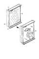
図2に示される冷蔵室扉(例えば右側冷蔵室扉1)は、扉内面を構成する樹脂製の内板10と、正面意匠面を構成する鋼板製の外板14と、内板10と外板14の周囲を覆う上面キャップ11、側面キャップ12、および下面キャップ13とを有して構成される。外板14と内板10と各キャップで形成される空間には図4に示されるように発断熱材18が充填されている。The refrigerator compartment door (for example, the right refrigerator compartment door 1) shown in FIG. 2 includes a resininner plate 10 constituting the door inner surface, a steel plateouter plate 14 constituting the front design surface, theinner plate 10 and the outer plate. Anupper surface cap 11, aside surface cap 12, and alower surface cap 13 that cover the periphery of theplate 14 are configured.Foamedheat insulating material 18 as the space formed by the cap and theinner plate 10 andouter plate 14 shown in FIG. 4 is filled.

外板14は、内板10の前面側(冷蔵庫30の正面側)に所定の間隔を隔てて内板10と平行に配置される。この外板14の四隅には雌ねじ部16が施された貫通穴9が形成され、意匠パネル17の四隅には、外板14の貫通穴9と対向する位置に貫通穴15が形成されている。  Theouter plate 14 is arranged on the front side of the inner plate 10 (the front side of the refrigerator 30) in parallel with theinner plate 10 with a predetermined interval. Throughholes 9 provided withfemale screw portions 16 are formed at the four corners of theouter plate 14, and throughholes 15 are formed at positions facing the throughholes 9 of theouter plate 14 at the four corners of thedesign panel 17. .

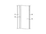
図3には外板14に意匠パネル17を固定するための2つの締結構造7、8が示されている。図3(a)の締結構造7は、意匠パネル17の正面側17aから意匠パネル17の貫通穴15に挿入されたねじ19が、外板14の貫通穴9に形成された雌ねじ部16に螺入されるように構成されている。図示例のように意匠パネル17を設置する場合、先ず、意匠パネル17の貫通穴15と外板14の貫通穴9とが連通するように外板14の正面側14aに意匠パネル17の背面側17bが設置される。次に、この状態で意匠パネル17の正面側17aから貫通穴15に向けてねじ19が挿入される。そして、貫通穴15に挿入した雄ねじ部19bを外板14の雌ねじ部16に螺入することで意匠パネル17が外板14の正面側14aに固定される。FIG. 3 shows twofastening structures 7 and 8 for fixing thedesign panel 17 to theouter plate 14. In the fastening structure 7 in FIG. 3A, thescrew 19 inserted into the throughhole 15 of thedesign panel 17 from thefront side 17 a of thedesign panel 17 is screwed into thefemale screw portion16 formed in the throughhole 9 of theouter plate 14. It is configured to be entered. When installing thedesign panel 17 as in the illustrated example, first, the back side of thedesign panel 17 is connected to thefront side 14a of theouter plate 14 so that the throughhole 15 of thedesign panel 17 and the throughhole 9 of theouter plate 14 communicate with each other. 17b is installed. Next, thescrew 19 is inserted from thefront side 17a of thedesign panel 17 toward the throughhole 15 in this state. Thedesign panel 17 is fixed to thefront side 14 a of theouter plate 14 by screwing themale screw portion 19 b inserted into the throughhole 15 into thefemale screw portion 16 of theouter plate 14.

図3(a)の例では、外板14の背面側14bに、雌ねじ部16と連通するように有底円筒状のねじ締結部16aが施されている。外板14の厚みは比較的薄いため、外板14の雌ねじ部16だけでねじ19を固定した場合、ねじ19の締め付け代が不十分となり所望の締め付けトルクを確保できない可能性があるが、図示例のようにねじ締結部16aを設けることにより、ねじ19の締め付け代を大きく取ることができる。  In the example of FIG. 3A, a bottomed cylindricalscrew fastening portion 16 a is provided on theback side 14 b of theouter plate 14 so as to communicate with thefemale screw portion 16. Since the thickness of theouter plate 14 is relatively thin, when thescrew 19 is fixed only by thefemale thread portion 16 of theouter plate 14, thescrew 19 is not sufficiently tightened and a desired tightening torque may not be ensured. By providing thescrew fastening portion 16a as shown in the example, the fastening allowance of thescrew 19 can be increased.

なお、図示例のねじ締結部16aは、発断熱材18を充填する際に発断熱材18が機外側へ漏れ出ることを防ぐため有底円筒状に形成されているが、ねじ締結部16aの形状はこれに限定されるものではなく、ねじ頭19aが外板14の正面側14aに接した状態でねじ19の締め付け代が十分確保されるように形成されていればよく、例えば無底円筒状に形成してもよいし、外板14の雌ねじ部16と連通するように背面側14bに固定した六角ナットをねじ締結部16aとしてもよい。Incidentally, thescrew fastening portion 16a of the illustrated example is formed into a bottomed cylindrical shape to prevent thefoamedheat insulating material 18 from leaking to the outboard side when chargingfoamedheat insulating material 18, a screw fastening portion The shape of 16a is not limited to this, and it is sufficient that thescrew 19 is formed so that thescrew 19 is in contact with thefront side 14a of theouter plate 14 so that thescrew 19 is sufficiently secured. It may be formed in a bottom cylindrical shape, or a hexagonal nut fixed to theback side 14b so as to communicate with thefemale thread portion 16 of theouter plate 14 may be used as thescrew fastening portion 16a.

また、ねじ19はドライバーなどの工具で締結するタイプのものでもよいが、工具を用いなくとも着脱できるように、例えばねじ頭19aの外周部にローレット加工を施したローレットビスをねじ19として用いることが望ましい。  Thescrew 19 may be of a type that can be fastened with a tool such as a screwdriver. However, for example, a knurled screw having a knurled outer periphery of thescrew head 19a is used as thescrew 19 so that thescrew 19 can be attached and detached without using a tool. Is desirable.

また図示例では、ねじ頭19aが意匠パネル17の正面側17aから突出しているが、雄ねじ部19bにザグリ加工を施して、皿ビスをねじ19として用いてもよい。皿ビス状のねじ19を用いることによって、ねじ19の頭部が意匠パネル17の正面側17aから突出しないようにすることができる。  In the illustrated example, thescrew head 19 a protrudes from thefront side 17 a of thedesign panel 17. However, a countersunk process may be applied to themale screw portion 19 b to use a countersunk screw as thescrew 19. By using the countersunkscrew 19, the head of thescrew 19 can be prevented from protruding from thefront side 17 a of thedesign panel 17.

一方、図3(b)の締結構造8は、外板14の背面側14bから外板14の貫通穴9に形成された雌ねじ部16に螺入され、かつ、意匠パネル17の貫通穴15を介して意匠パネル17の正面側に突出するねじ19が、意匠パネル17の正面側17aに配置されるナット20に螺入されるように構成されている。締結構造8では、予め外板14の背面側14bから雌ねじ部16に向けて雄ねじ部19bが螺入され、雄ねじ部19bは、ねじ頭19aが背面側14bに接した状態で固定されている。そして図示例のように意匠パネル17を設置する場合、外板14の正面側14aに突出した雄ねじ部19bが意匠パネル17の貫通穴15に挿入されるように、外板14の正面側14aに意匠パネル17の背面側17bが設置される。このように意匠パネル17を設置することで貫通穴15に挿入された雄ねじ部19bの端部が意匠パネル17の正面側17aに突出するため、その端部にナット20の雌ねじ部20aを締結することで意匠パネル17が外板14の正面側14aに固定される。なお、ナット20は、工具を用いなくとも着脱できるように、例えば外周部にローレット加工を施したローレットナットをナット20として用いることが望ましい。  On the other hand, thefastening structure 8 of FIG. 3B is screwed into thefemale screw portion 16 formed in the throughhole 9 of theouter plate 14 from theback surface side 14b of theouter plate 14, and the throughhole 15 of thedesign panel 17 is inserted. Ascrew 19 protruding to the front side of thedesign panel 17 is screwed into anut 20 disposed on thefront side 17 a of thedesign panel 17. In thefastening structure 8, amale screw portion 19 b is screwed in advance from theback side 14 b of theouter plate 14 toward thefemale screw portion 16, and themale screw portion 19 b is fixed in a state where thescrew head 19 a is in contact with theback side 14 b. And when installing thedesign panel 17 as in the illustrated example, themale screw portion 19b protruding from thefront side 14a of theouter plate 14 is inserted into thefront side 14a of theouter plate 14 so that it is inserted into the throughhole 15 of thedesign panel 17. Theback side 17b of thedesign panel 17 is installed. Since the end portion of themale screw portion 19b inserted into the throughhole 15 protrudes to thefront side 17a of thedesign panel 17 by installing thedesign panel 17 in this manner, thefemale screw portion 20a of thenut 20 is fastened to the end portion. Thus, thedesign panel 17 is fixed to thefront side 14 a of theouter plate 14. For example, a knurled nut whose outer peripheral portion is knurled is preferably used as thenut 20 so that thenut 20 can be attached and detached without using a tool.

外板14の正面側14aに設置された意匠パネル17を取り外す場合、前述した図3(a)の構造では、ねじ19をある程度外して雄ねじ部19bの先端部が僅かに雌ねじ部16へ螺入された状態で、意匠パネル17が落下しないように押さえながらねじ19を取り外せばよい。これに対して図3(b)の構造では、ナット20を外しても意匠パネル17が即座に落下することがないため、全てのナット20を外した後に意匠パネル17を取り外せばよい。  When thedesign panel 17 installed on thefront side 14a of theouter plate 14 is removed, in the structure shown in FIG. 3A, thescrew 19 is removed to some extent, and the tip of themale screw portion 19b is slightly screwed into thefemale screw portion 16. In this state, thescrews 19 may be removed while holding thedesign panel 17 so that it does not fall. On the other hand, in the structure of FIG. 3B, thedesign panel 17 does not fall immediately even if thenut 20 is removed. Therefore, thedesign panel 17 may be removed after removing all the nuts 20.

図5は、図2に示す意匠パネルに代えて他の意匠パネルを取り付ける状態を示す冷蔵室扉の分解斜視図である。図5の構成例では、図2に示される上面キャップ11、側面キャップ12、および下面キャップ13が内板10と一体に固定されているが、基本的な構成は図2の構成例と同様である。相違点は図2に示す意匠パネル17とは異なる意匠パネル17−1が用いられている点である。前述したように外板14の正面側14aに設置された意匠パネル17(図2参照)を取り外して、意匠パネル17の図柄とは異なる図柄が描かれた意匠パネル17−1へ交換する場合でも図3に示される締結構造7、8によって交換作業を容易に行うことができる。  FIG. 5 is an exploded perspective view of the refrigerator compartment door showing a state in which another design panel is attached instead of the design panel shown in FIG. 2. In the configuration example of FIG. 5, theupper surface cap 11, theside cap 12, and thelower surface cap 13 shown in FIG. 2 are fixed integrally with theinner plate 10, but the basic configuration is the same as the configuration example of FIG. is there. The difference is that a design panel 17-1 different from thedesign panel 17 shown in FIG. 2 is used. Even when the design panel 17 (see FIG. 2) installed on thefront side 14a of theouter plate 14 is removed as described above and replaced with the design panel 17-1 on which a design different from the design of thedesign panel 17 is drawn. The replacement work can be easily performed by thefastening structures 7 and 8 shown in FIG.

図6は、従来の冷蔵庫の扉の外観を表す第1の図であり、前述した特許文献1に開示される構造を表すものである。この従来の構造では、冷蔵庫本体の前面開口を閉塞する扉本体52の前面に有色透明あるいは半透明板のカバー50が装着され、当該カバー50を扉本体52に装着した後に、カバー50と扉本体52の組の上方より上キャップ54が装着され、カバー50と扉本体52の組の下方より下キャップ53が装着される。ところがこの従来の構造では、カバー50を扉本体52に装着した後に、カバー50と扉本体52の組の上方より上キャップ54が装着され、カバー50と扉本体52の組の下方より下キャップ53が装着されるため、カバー50と扉本体52の間に組み込まれた意匠柄51を交換する場合、扉本体52を分解するような行程を経なければなければならず、ユーザが意匠柄を任意に変更することが困難である。  FIG. 6 is a first view illustrating the appearance of a conventional refrigerator door, and represents the structure disclosed inPatent Document 1 described above. In this conventional structure, a colored transparent ortranslucent plate cover 50 is mounted on the front surface of the doormain body 52 that closes the front opening of the refrigerator main body, and thecover 50 and the door main body are mounted after thecover 50 is mounted on the doormain body 52. Theupper cap 54 is attached from above the pair of 52, and thelower cap 53 is attached from below the pair of thecover 50 and thedoor body 52. However, in this conventional structure, after thecover 50 is mounted on thedoor body 52, theupper cap 54 is mounted from above the set of thecover 50 anddoor body 52, and thelower cap 53 is mounted from below the set of thecover 50 anddoor body 52. Therefore, when thedesign pattern 51 incorporated between thecover 50 and thedoor body 52 is to be replaced, it is necessary to go through a process of disassembling thedoor body 52, and the user can arbitrarily select the design pattern. It is difficult to change to.

図7は、従来の冷蔵庫の扉の外観を表す第2の図であり、前述した特許文献2に開示される構造を表すものである。この従来の構造では、扉本体60の前面に配置される前面板と、その前面板の前側に配置され前面板から所定間隔離れた位置に配置される透明板62と、扉本体60の両側縁部に配置される一対の巻き取り機構61と、各巻き取り機構内の巻き取り軸間に連なるように設けられ前面板と透明板62との間の隙間において移動可能に配置される意匠柄を施したフィルム63と、を有して構成されている。ところがこの従来の構造では、意匠柄を施したフィルム63の巻取るため扉本体60に大きなモジュール(巻き取り機構61など)を設ける必要があり、比較的狭い空間に冷蔵庫が設置された場合には扉本体60の開角度が大きく取れず、食品の出し入れが難しくなるという課題があった。また巻取り機構61が扉本体60の前面に張り出した形となるため美観を損なうと共に、巻取り機構61を構成する部品が多く、製作コストの増加を招くという課題もあった。  FIG. 7 is a second view showing the appearance of a door of a conventional refrigerator, and represents the structure disclosed inPatent Document 2 described above. In this conventional structure, a front plate disposed on the front surface of the doormain body 60, atransparent plate 62 disposed on the front side of the front plate and spaced apart from the front plate, and both side edges of the door main body 60 A pair of windingmechanisms 61 disposed in the section, and a design pattern that is provided so as to be continuous between the winding shafts in each winding mechanism and is movably disposed in the gap between the front plate and thetransparent plate 62. And the appliedfilm 63. However, in this conventional structure, it is necessary to provide a large module (windingmechanism 61 or the like) in thedoor body 60 in order to wind thefilm 63 with the design pattern, and when a refrigerator is installed in a relatively narrow space. There was a problem that the opening angle of thedoor body 60 could not be made large and it was difficult to put in and out food. In addition, since the windingmechanism 61 protrudes from the front surface of thedoor body 60, the appearance is impaired, and there are many parts that constitute the windingmechanism 61, resulting in an increase in manufacturing cost.

図8は、従来の冷蔵庫の扉の外観を表す第3の図であり、前述した特許文献3に開示される構造を表すものである。この従来の構造では、扉本体の周縁側部74と、周縁側部74と扉本体の前面との間に形成された溝の上方から挿入されて扉本体の前面の一部を覆うように取り付けられる化粧板76と、前記溝の上方から挿入された化粧板76の上端に設けられた仕切り板75を介して化粧板76の上部に配置される透明または半透明の合成樹脂板73と、周縁側部74の上部の開口部を閉塞するように配置される押え板71と、を有して構成されており、押え板71を周縁側部74に固定するためのねじ70を外した後、合成樹脂板73と扉本体との間に絵画72などの意匠柄を挿入することで様々な意匠柄をユーザに提供可能に構成されている。ところがこの従来の構造では、押え板71の取外しによって扉周囲のガスケットの密着性が低下するだけでなく、意匠柄変更時には上方向にのみ意匠柄が抜き差しされるため天井が低い環境では意匠柄の出し入れが難しくなると共に、高所作業となり危険であるため安全性に課題が残る。  FIG. 8 is a third view showing the appearance of a conventional refrigerator door, and shows the structure disclosed inPatent Document 3 described above. In this conventional structure, the door body is inserted so as to cover a part of the front side of the door body by being inserted from above theperipheral side part 74 of the door body and the groove formed between theperipheral side part 74 and the front surface of the door body. A decorative plate 76, a transparent or translucentsynthetic resin plate 73 disposed above the decorative plate 76 via apartition plate 75 provided at the upper end of the decorative plate 76 inserted from above the groove, Apresser plate 71 disposed so as to close the upper opening of theedge side portion 74, and after removing thescrew 70 for fixing thepresser plate 71 to theperipheral side portion 74, By inserting a design pattern such as apainting 72 between thesynthetic resin plate 73 and the door body, various design patterns can be provided to the user. However, in this conventional structure, not only the adhesion of the gasket around the door is lowered by the removal of thepresser plate 71, but the design pattern is inserted / removed only in the upward direction when the design pattern is changed. It becomes difficult to put in and out, and it is dangerous to work at a high place, so there are still problems with safety.

これらの従来の構造に対して本実施の形態に係る冷蔵庫30は、図3に示される締結構造7、8を用いて外板14に意匠パネル17を固定することができるため、図6および図8に示される構造のように扉本体を分解するような行程が不要であるため、ユーザが容易に意匠柄を変更することが可能である。また図7に示される構造のように扉本体に大きなモジュールを設ける必要がないため、比較的狭い空間に冷蔵庫が設置された場合でも扉本体の開角度が大きく取れ、食品の出し入れが難しくなることがない。また美観を損なうこともなく、さらに製作コストの増加を招くこともない。  Since therefrigerator 30 according to the present embodiment can fix thedesign panel 17 to theouter plate 14 using thefastening structures 7 and 8 shown in FIG. Since the process which decomposes | disassembles a door main body like the structure shown by 8 is unnecessary, a user can change a design pattern easily. Moreover, since it is not necessary to provide a large module in the door body as in the structure shown in FIG. 7, even when the refrigerator is installed in a relatively narrow space, the door body can be opened at a large angle, making it difficult to put food in and out. There is no. In addition, the aesthetic appearance is not impaired and the production cost is not increased.

なお、本実施の形態に係る貫通穴15および雌ねじ部16の数は、図示例のように各々4つに限定されるものではないが、図示例のように貫通穴15および雌ねじ部16を各々4つ設けることにより、貫通穴15および雌ねじ部16が各々4つ未満である場合に比べて、意匠パネル17を外板14に堅牢に固定することができる。特に観音開き式の冷蔵室扉(右側冷蔵室扉1、左側冷蔵室扉6)は、例えば開放時に冷蔵庫30の横側に位置する壁へ干渉する虞があることから、扉の開閉時における局所的な力が意匠パネル17に作用する虞がある。このような衝撃に耐えるように堅牢に意匠パネル17を固定するためには本実施の形態に係る冷蔵庫30のように貫通穴15および雌ねじ部16を各々4つ設けることが有効であり、このように構成することで局所的な力が分散され、意匠パネル17が変形あるいは損傷するのを効果的に防止することができる。  The numbers of the throughholes 15 and thefemale screw portions 16 according to the present embodiment are not limited to four each as in the illustrated example, but each of the throughholes 15 and thefemale screw portions 16 as in the illustrated example. By providing four, thedesign panel 17 can be firmly fixed to theouter plate 14 as compared with the case where each of the throughholes 15 and thefemale screw portions 16 is less than four. In particular, the open door type refrigerator compartment door (the rightrefrigerator compartment door 1 and the left refrigerator compartment door 6) may interfere with a wall located on the side of therefrigerator 30 when opened, for example. May be exerted on thedesign panel 17. In order to firmly fix thedesign panel 17 so as to withstand such an impact, it is effective to provide four throughholes 15 and fourfemale thread portions 16 as in therefrigerator 30 according to the present embodiment. By being configured in this manner, local forces are dispersed, and thedesign panel 17 can be effectively prevented from being deformed or damaged.

また本実施の形態では、図3に示される締結構造7、8を右側冷蔵室扉1に適用して意匠パネル17を取り付ける例を説明したが、図3に示される締結構造7、8は観音開き式の冷蔵室扉以外の扉に対しても適用することができる。  Further, in the present embodiment, an example in which thedesign panel 17 is attached by applying thefastening structures 7 and 8 shown in FIG. 3 to the rightrefrigerator compartment door 1 is described, but thefastening structures 7 and 8 shown in FIG. It can be applied to doors other than the refrigerator door of the type.

また本実施の形態では、意匠パネル17の四隅に貫通穴15が形成され、この貫通穴15と対向する位置に外板14の雌ねじ部16が形成されているが、貫通穴15と雌ねじ部16の位置はこれに限定されるものではなく、意匠パネル17および外板14の中央部を中心として対称な位置に形成すればよい。例えば意匠パネル17の上辺部の中央に貫通穴15を形成する場合には意匠パネル17の下辺部の中央にも貫通穴15を形成し、外板14の雌ねじ部16もこれらの貫通穴15と対向する位置に形成されるものとする。  In the present embodiment, throughholes 15 are formed at the four corners of thedesign panel 17, and thefemale screw part 16 of theouter plate 14 is formed at a position facing the throughhole 15. However, the throughhole 15 and thefemale screw part 16 are formed. This position is not limited to this, and it may be formed at a symmetrical position with the central portions of thedesign panel 17 and theouter plate 14 as the center. For example, when the throughhole 15 is formed at the center of the upper side portion of thedesign panel 17, the throughhole 15 is also formed at the center of the lower side portion of thedesign panel 17, and thefemale screw portion 16 of theouter plate 14 is also connected to these throughholes 15. It shall be formed in the position which opposes.

以上に説明したように本実施の形態に係る冷蔵庫30は、冷蔵庫本体の外箱31に取り付けられた扉(1〜5の扉の何れか)と、この扉の前面部を形成する外板14の正面側14aに設置される意匠パネル17と、を備え、意匠パネル17は、意匠パネル17に形成された第1の穴(貫通穴15)と外板14において第1の穴と対向する位置に形成された第2の穴(貫通穴9)とに挿入される締結部(ねじ19)と、この締結部が締結される被締結部(雌ねじ部16、雌ねじ部16b、ナット20、雌ねじ部20a)と、から成る締結構造7、8により、外板14の正面側14aに固定される。この構成により、冷蔵庫30としての基本機能を確保しつつ、使用者が容易にかつ安全に意匠柄を変更することが可能である。また外板14の正面側14aには意匠パネル17、ねじ19の一部、ナット20などが配置されるだけであるため、扉本体の開角度が大きく取れ、食品の出し入れが難しくなることがなく、美観を損なうこともない。また複雑な機構を用いる必要がないため製作コストを抑えることができると共に、構造が簡素化されるため、信頼性が向上し、冷蔵庫30を構成する部品の製造時の歩留りが向上し、当該部品の原材料の減容化や包装の減量化を図ることができる。  As described above, therefrigerator 30 according to the present embodiment includes a door (any one of thedoors 1 to 5) attached to theouter box 31 of the refrigerator body and theouter plate 14 forming the front portion of the door. Adesign panel 17 installed on thefront side 14a of thefirst design panel 17, thedesign panel 17 facing the first hole in the first hole (through hole 15) formed in thedesign panel 17 and theouter plate 14. Fastening portion (screw 19) to be inserted into the second hole (through hole 9) formed in the screw, and fastened portion (female screw portion 16,female screw portion 16b,nut 20, female screw portion to which the fastening portion is fastened. 20a) is fixed to thefront side 14a of theouter plate 14 byfastening structures 7, 8. With this configuration, the user can easily and safely change the design pattern while ensuring the basic functions of therefrigerator 30. Further, since thedesign panel 17, a part of thescrew 19, anut 20, and the like are only disposed on thefront side 14 a of theouter plate 14, the door body can be opened at a large angle, and it is not difficult to put food in and out. , No loss of aesthetics. Further, since it is not necessary to use a complicated mechanism, the manufacturing cost can be suppressed and the structure is simplified, so that the reliability is improved, the yield at the time of manufacturing the parts constituting therefrigerator 30 is improved, and the parts The volume of raw materials and packaging can be reduced.

実施の形態2.
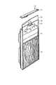
図9は、本発明の実施の形態2に係る冷蔵庫の冷蔵室扉と冷蔵室扉に取り付けられる透明パネルの分解斜視図である。実施の形態1との相違点は意匠パネル17、17−1の代わりに、有色透明、無色透明、または半透明板の材料で形成された透明パネル17−2が用いられている点である。以下、実施の形態1と同一部分には同一符号を付してその説明を省略し、ここでは異なる部分についてのみ述べる。
Embodiment 2. FIG.
FIG. 9 is an exploded perspective view of the refrigerator compartment door and the transparent panel attached to the refrigerator compartment door according toEmbodiment 2 of the present invention. The difference from the first embodiment is that a transparent panel 17-2 formed of a colored transparent, colorless transparent, or translucent plate material is used instead of thedesign panels 17 and 17-1. Hereinafter, the same reference numerals are given to the same parts as those in the first embodiment, and the description thereof is omitted, and only different parts will be described here.

図9に示される透明パネル17−2と外板14との間には意匠柄を施したシート状の部材(意匠シート21)が介在する。すなわち透明パネル17−2と外板14とで意匠シート21を挟む形となっており、透明パネル17−2を介して意匠シート21の意匠柄を使用者に提供することができる。なお、図示例では一例として意匠シート21の四隅において外板14の貫通穴9と対向する位置に貫通穴15−1が形成されている。これは意匠シート21の位置ずれを防止するための措置であり、意匠シート21がねじ19に干渉しない大きさであれば貫通穴15−1は省いてもよい。  A sheet-like member (design sheet 21) having a design pattern is interposed between the transparent panel 17-2 and theouter plate 14 shown in FIG. That is, thedesign sheet 21 is sandwiched between the transparent panel 17-2 and theouter plate 14, and the design pattern of thedesign sheet 21 can be provided to the user via the transparent panel 17-2. In the illustrated example, through holes 15-1 are formed at positions facing the throughholes 9 of theouter plate 14 at the four corners of thedesign sheet 21 as an example. This is a measure for preventing the positional deviation of thedesign sheet 21, and the through hole 15-1 may be omitted as long as thedesign sheet 21 does not interfere with thescrew 19.

意匠シート21を交換する場合には、実施の形態1の意匠パネル17と同様に、締結構造7のねじ19を緩め、または締結構造8のナット20を緩めた上で、外板14の正面側14aに設置された意匠シート21を取り外し、異なる図柄が描かれた意匠シート21へ交換する。その後、意匠シート21正面側に透明パネル17−2を取り付けて締結構造7のねじ19を締結し、または締結構造8のナット20を締結する。When thedesign sheet 21 is to be replaced, the front side of theouter plate 14 after loosening thescrew 19 of the fastening structure 7 or loosening thenut 20 of thefastening structure 8, as in thedesign panel 17 of the first embodiment. Thedesign sheet 21 installed in 14a is removed and replaced with adesign sheet 21 on which a different design is drawn. Then, the transparent panel 17-2 is attached to the front side of thedesignsheet 21 , and thescrew 19 of the fastening structure 7 is fastened, or thenut 20 of thefastening structure 8 is fastened.

このように透明パネル17−2を用いることで実施の形態1と同様の効果を得ることができると共に、意匠シート21の大きさに対して制約を受けることがなくなり、実施の形態1に比べてより多くの意匠柄を選択することが可能となる。Thus, while using the transparent panel 17-2, the effect similar toEmbodiment 1 can be acquired, and there is no restriction | limiting with respect to the magnitude | size of thedesignsheet 21 , Compared withEmbodiment 1. It becomes possible to select more design patterns.

実施の形態3.
図10は、本発明の実施の形態3に係る冷蔵庫の冷蔵室扉と冷蔵室扉に取り付けられる透明パネルの分解斜視図である。実施の形態2との相違点は、下面キャップ13に透明パネル17−2の受け形状22(鍔部22aおよび係止部22b)が追加されている点である。以下、実施の形態2と同一部分には同一符号を付してその説明を省略し、ここでは異なる部分についてのみ述べる。
Embodiment 3 FIG.
FIG. 10 is an exploded perspective view of the refrigerator compartment door and the transparent panel attached to the refrigerator compartment door according toEmbodiment 3 of the present invention. A difference from the second embodiment is that a receiving shape 22 (aflange portion 22a and a lockingportion 22b) of the transparent panel 17-2 is added to thelower surface cap 13. Hereinafter, the same reference numerals are given to the same parts as those of the second embodiment, and the description thereof is omitted, and only different parts will be described here.

図10(a)に示されるように下面キャップ13には透明パネル17−2の受け形状22が形成されている。図10(b)は図10(a)に示される符号Aの箇所を拡大したものであり、受け形状22は下面キャップ13と一体に形成され正面側に突出する鍔部22aと、鍔部22aの先端部と一体に形成され垂直方向に延びる係止部22bとから成る。図示例では受け形状22が下面キャップ13の端部付近に各々1ずつ(計2カ所)設けられているが、受け形状22の数は2つに限定されるものではない。また本実施の形態では透明パネル17−2が用いられているが、透明パネル17−2の代わりに意匠パネル17を用いてもよい。  As shown in FIG. 10A, thebottom cap 13 is formed with a receivingshape 22 for the transparent panel 17-2. FIG. 10 (b) is an enlarged view of the portion indicated by the symbol A shown in FIG. 10 (a). The receivingshape 22 is formed integrally with thelower surface cap 13 and protrudes to the front side, and theflange portion 22a. And a lockingportion 22b that is formed integrally with the distal end portion and extends in the vertical direction. In the illustrated example, one receivingshape 22 is provided in the vicinity of the end of the bottom cap 13 (two in total), but the number of receivingshapes 22 is not limited to two. Moreover, although the transparent panel 17-2 is used in this Embodiment, you may use thedesign panel 17 instead of the transparent panel 17-2.

このように扉の背面部を形成する内板10と外板14の周囲を覆うキャップ(下面キャップ13)には、意匠パネル(意匠パネル17、透明パネル17−2)の下部に係り止めする受け形状22が形成されている。これにより、例えば締結構造7のねじ19を外し、または締結構造8のナット20を外した場合でも、透明パネル17−2を落下させることなく保持することができる。従って、実施の形態2と同様の効果を得ることができると共に、透明パネル17−2を外板14から完全に取り外してから意匠シート21(図9参照)を交換する必要がないため実施の形態2に比べて意匠柄の変更が容易になる。  In this way, the cap (lower surface cap 13) covering the periphery of theinner plate 10 and theouter plate 14 forming the back surface portion of the door is latched to the lower portion of the design panel (design panel 17, transparent panel 17-2). Ashape 22 is formed. Thereby, for example, even when thescrew 19 of the fastening structure 7 is removed or thenut 20 of thefastening structure 8 is removed, the transparent panel 17-2 can be held without dropping. Therefore, it is possible to obtain the same effect as that of the second embodiment, and it is not necessary to replace the design sheet 21 (see FIG. 9) after completely removing the transparent panel 17-2 from theouter plate 14, and thus the embodiment. Compared to 2, the design pattern can be easily changed.

実施の形態4.
図11は、本発明の実施の形態4に係る冷蔵庫の冷蔵室扉と冷蔵室扉に取り付けられる透明パネルの分解斜視図である。実施の形態3との相違点は、受け形状22の代わりにヒンジ23が用いられている点である。以下、実施の形態3と同一部分には同一符号を付してその説明を省略し、ここでは異なる部分についてのみ述べる。
Embodiment 4 FIG.
FIG. 11 is an exploded perspective view of the refrigerator compartment door and the transparent panel attached to the refrigerator compartment door according toEmbodiment 4 of the present invention. A difference from the third embodiment is that ahinge 23 is used instead of the receivingshape 22. Hereinafter, the same reference numerals are given to the same parts as those of the third embodiment, and the description thereof is omitted, and only different parts will be described here.

図11に示されるように側面キャップ12にはヒンジ23が設けられている。図示例ではヒンジ23が側面キャップ12の端部付近に各々1ずつ(計2カ所)設けられているが、ヒンジ23の数は2つに限定されるものではない。また図11には、ねじ19すなわち締結構造7で透明パネル17−2を固定した場合の例が示されているが締結構造8で透明パネル17−2を固定する場合も同様である。  As shown in FIG. 11, theside cap 12 is provided with ahinge 23. In the illustrated example, onehinge 23 is provided near each end of the side cap 12 (two in total), but the number ofhinges 23 is not limited to two. FIG. 11 shows an example in which the transparent panel 17-2 is fixed with thescrew 19, that is, the fastening structure 7. However, the same applies to the case where the transparent panel 17-2 is fixed with thefastening structure 8.

このように内板10と外板14の周囲を覆うキャップ(側面キャップ12)には、意匠パネル(意匠パネル17、透明パネル17−2)の側面を保持するヒンジ23が形成されている。これにより、例えば締結構造7のねじ19を外し、または締結構造8のナット20を外した場合でも、ヒンジ23のヒンジ軸を中心として透明パネル17−2を開閉することができ、実施の形態3と同様に透明パネル17−2を保持することができる。従って、実施の形態3と同様の効果を得ることができると共に、以下のような効果を得ることができる。実施の形態3では透明パネル17−2の上側のねじ19やナット20が外されたとき、透明パネル17−2が受け形状22に設置される形となるため、透明パネル17−2の下端部付近では透明パネル17−2と外板14の間の隙間が狭くなり、意匠シート21がこの隙間に挟まるなどして交換作業が難しい場合も想定される。これに対して実施の形態4では、扉の横方向から意匠シート21の交換ができる。またヒンジ23で透明パネル17−2が保持されているため、ユーザは透明パネル17−2が倒れないように透明パネル17−2を押さえる必要がない。このように実施の形態4によれば実施の形態3に比べて意匠柄の変更が容易になる。  Thus, the cap (side cap 12) covering the periphery of theinner plate 10 and theouter plate 14 is formed with ahinge 23 that holds the side surface of the design panel (design panel 17, transparent panel 17-2). Thereby, for example, even when thescrew 19 of the fastening structure 7 is removed or thenut 20 of thefastening structure 8 is removed, the transparent panel 17-2 can be opened and closed around the hinge axis of thehinge 23, and the third embodiment The transparent panel 17-2 can be held in the same manner as described above. Therefore, the same effects as in the third embodiment can be obtained, and the following effects can be obtained. InEmbodiment 3, when theupper screw 19 andnut 20 of the transparent panel 17-2 are removed, the transparent panel 17-2 is installed in the receivingshape 22, so that the lower end of the transparent panel 17-2 In the vicinity, the gap between the transparent panel 17-2 and theouter plate 14 is narrowed, and it may be difficult to exchange thedesign sheet 21 due to thedesign sheet 21 being sandwiched in the gap. On the other hand, inEmbodiment 4, thedesign sheet 21 can be replaced from the lateral direction of the door. Further, since the transparent panel 17-2 is held by thehinge 23, the user does not need to press the transparent panel 17-2 so that the transparent panel 17-2 does not fall down. Thus, according to the fourth embodiment, the design pattern can be easily changed as compared with the third embodiment.

また、以上に説明した実施の形態1〜4によれば、意匠パネル17、透明パネル17−2、および意匠シート21が発断熱材18の発泡熱や発泡圧による影響を受けることがなくなり、意匠パネル17、透明パネル17−2、および意匠シート21に使用する部材に対して熱的な制約を受けることがなくなり、製造原価を抑制することができ、かつ、意匠柄の不良による歩留りが大きく改善される。Further, according to the first to fourth embodiments described above,design panel 17, the transparent panel 17-2, and thedesign sheet 21 no longer be affected by foaming heat and foaming pressure of thefoamedheat insulation material 18, The members used for thedesign panel 17, the transparent panel 17-2, and thedesign sheet 21 are not subjected to thermal restrictions, the manufacturing cost can be suppressed, and the yield due to the defective design pattern is large. Improved.

なお、以上の実施の形態に示した構成は、本発明の構成の一例であり、別の公知の技術と組み合わせることも可能であるし、本発明の要旨を逸脱しない範囲で、一部を省略する等、変更して構成することも可能であることは言うまでもない。  Note that the configuration shown in the above embodiment is an example of the configuration of the present invention, and can be combined with another known technique, and a part thereof is omitted without departing from the gist of the present invention. Needless to say, it is possible to change the configuration.

以上のように、本発明は、冷蔵庫に適用可能であり、特に、設置場所の制約を受けることなく容易に意匠柄を変更することができる発明として有用である。  As described above, the present invention can be applied to a refrigerator, and is particularly useful as an invention in which a design pattern can be easily changed without being restricted by an installation location.

1 右側冷蔵室扉、2 製氷室扉、3 切替室扉、4 冷凍室扉、5 野菜室扉、6 左側冷蔵室扉、7 締結構造、8 締結構造、9 貫通穴(第2の穴)、10 内板、11 上面キャップ、12 側面キャップ、13 下面キャップ、14 外板、14a 正面側、14b 背面側、15 貫通穴(第1の穴)、15−1 貫通穴、16 雌ねじ部(被締結部)、16a ねじ締結部、16 雌ねじ部(被締結部)、17,17−1 意匠パネル、17−2 透明パネル、17a 正面側、17b 背面側、18 発断熱材、19 ねじ(締結部)、19a ねじ頭、19b 雄ねじ部、20 ナット(被締結部)、20a 雌ねじ部(被締結部)、21 意匠シート、22 受け形状、22a 鍔部、22b 係止部、23 ヒンジ、30 冷蔵庫、31 外箱。1 right refrigerator door, 2 ice making door, 3 switching chamber door, 4 freezer door, 5 vegetable door, 6 left refrigerator door, 7 fastening structure, 8 fastening structure, 9 through hole (second hole), DESCRIPTION OFSYMBOLS 10 Inner plate, 11 Upper surface cap, 12 Side cap, 13 Lower surface cap, 14 Outer plate, 14a Front side, 14b Rear side, 15 Through hole (1st hole), 15-1 Through hole, 16 Female thread part (fastened) parts), 16ascrew fastening portion16 internally threaded portion (fastened portions), 17,17-1 design panel, 17-2 transparent panel, 17a front, 17b back side, 18shotsfoam insulation 19 screw (fastening portion ), 19a Screw head, 19b Male screw part, 20 Nut (fastened part), 20a Female screw part (fastened part), 21 Design sheet, 22 Receiving shape, 22a Hook part, 22b Locking part, 23 Hinge, 30 Refrigerator, 31 Outer box.

Claims (6)

Translated fromJapanese
冷蔵庫本体の外箱に取り付けられた扉と、
前記扉の前面部を形成する外板の正面側に設置される意匠パネルと、
を備え、
前記意匠パネルは、前記意匠パネルに形成された第1の穴と前記外板において前記第1の穴と対向する位置に形成された第2の穴とに挿入される締結部と、この締結部が締結される被締結部と、から成る締結構造により、前記外板の正面側に固定され
前記第1の穴は、前記意匠パネルの四隅に形成され、
前記第2の穴は、前記外板の四隅に形成され、
前記締結部は、前記意匠パネルの四隅のそれぞれに形成される前記第1の穴に挿入されると共に、前記外板の四隅のそれぞれに形成される前記第2の穴に挿入されて前記被締結部に締結されることを特徴とする冷蔵庫。
A door attached to the outer box of the refrigerator body;
A design panel installed on the front side of the outer plate forming the front portion of the door;
With
The design panel includes a fastening portion that is inserted into a first hole formed in the design panel and a second hole formed at a position opposite to the first hole in the outer plate, and the fastening portion. Is fastened to the front side of the outer plate by a fastening structure consisting of a fastened part to be fastened,
The first holes are formed at four corners of the design panel,
The second holes are formed at the four corners of the outer plate,
The fastening portion is inserted into the first hole formed at each of the four corners of the design panel, and is inserted into the second hole formed at each of the four corners of the outer plate to be fastened. refrigerator characterized by Rukotois fastened to the part.
前記締結構造は、前記意匠パネルの正面側から前記第1の穴に挿入された前記締結部が、前記外板の前記第2の穴に形成された前記被締結部に螺入されるように構成され
前記被締結部は、前記外板の前記意匠パネルとは反対側に固定される円筒状のねじ締結部であり、
前記ねじ締結部には、前記第2の穴と連通する雌ねじ部が形成され、
前記第1の穴及び前記第2の穴に挿入される前記締結部の雄ねじ部は、前記雌ねじ部に締結されていることを特徴とする請求項1に記載の冷蔵庫。
The fastening structure is such that the fastening part inserted into the first hole from the front side of the design panel is screwed into the fastened part formed in the second hole of the outer plate. Configured,
The fastened part is a cylindrical screw fastening part fixed to the opposite side of the design panel of the outer plate,
The screw fastening portion is formed with a female screw portion communicating with the second hole,
2. The refrigerator according to claim 1, wherein a male screw portion of the fastening portion that is inserted into the first hole and the second hole is fastened to the female screw portion .
前記締結構造は、前記外板の背面側から前記外板の前記第2の穴に形成された前記被締結部に螺入され、かつ、前記意匠パネルの前記第1の穴を介して前記意匠パネルの正面側に突出する前記締結部が、前記意匠パネルの正面側に配置される前記被締結部に螺入されるように構成され
前記第2の穴には、雌ねじ部が形成され、
前記締結部の雄ねじ部は、前記雌ねじ部に締結されると共に、前記締結部のねじ頭が前記外板の前記意匠パネルとは反対側に接した状態で固定されていることを特徴とする請求項1に記載の冷蔵庫。
The fastening structure is screwed into the fastened portion formed in the second hole of the outer plate from the back side of the outer plate, and the design via the first hole of the design panel. The fastening part protruding to the front side of the panel is configured to be screwed into the fastened part disposed on the front side of the design panel,
An internal thread portion is formed in the second hole,
The male screw portion of the fastening portion is fastened to the female screw portion, and is fixed in a state where a screw head of the fastening portion is in contact with a side opposite to the design panel of the outer plate. Item 10. The refrigerator according to Item 1.
前記意匠パネルは、有色透明、無色透明、または半透明板の材質で形成されていることを特徴とする請求項1から3の何れか1項に記載の冷蔵庫。  The refrigerator according to any one of claims 1 to 3, wherein the design panel is made of a colored transparent, colorless transparent, or translucent plate material. 前記扉の背面部を形成する内板と前記外板の周囲を覆うキャップには、前記意匠パネルの下部に係り止めする受け形状が形成されていることを特徴とする請求項1から4の何れか1項に記載の冷蔵庫。  The cap which covers the circumference | surroundings of the inner board and the said outer board which form the back part of the said door is formed in the receiving shape which latches to the lower part of the said design panel, Any one of Claim 1 to 4 characterized by the above-mentioned. The refrigerator of Claim 1. 前記扉の背面部を形成する内板と前記外板の周囲を覆うキャップには、前記意匠パネルの側面を保持するヒンジが形成されていることを特徴とする請求項1から4の何れか1項に記載の冷蔵庫。  The hinge which hold | maintains the side surface of the said design panel is formed in the cap which covers the circumference | surroundings of the inner board and the said outer board which form the back part of the said door, The any one of Claim 1 to 4 characterized by the above-mentioned. The refrigerator according to item.
JP2014085497A2014-04-172014-04-17 refrigeratorExpired - Fee RelatedJP6207453B2 (en)

Priority Applications (2)

Application NumberPriority DateFiling DateTitle
JP2014085497AJP6207453B2 (en)2014-04-172014-04-17 refrigerator
CN201520225569.8UCN204630231U (en)2014-04-172015-04-14Refrigerator

Applications Claiming Priority (1)

Application NumberPriority DateFiling DateTitle
JP2014085497AJP6207453B2 (en)2014-04-172014-04-17 refrigerator

Publications (2)

Publication NumberPublication Date
JP2015206478A JP2015206478A (en)2015-11-19
JP6207453B2true JP6207453B2 (en)2017-10-04

Family

ID=54049248

Family Applications (1)

Application NumberTitlePriority DateFiling Date
JP2014085497AExpired - Fee RelatedJP6207453B2 (en)2014-04-172014-04-17 refrigerator

Country Status (2)

CountryLink
JP (1)JP6207453B2 (en)
CN (1)CN204630231U (en)

Families Citing this family (9)

* Cited by examiner, † Cited by third party
Publication numberPriority datePublication dateAssigneeTitle
CN107270610A (en)*2016-04-072017-10-20东芝生活电器株式会社Refrigerator
CN107677035A (en)*2017-11-012018-02-09合肥华凌股份有限公司A kind of refrigerator door and refrigerator
CN109907594A (en)*2019-03-262019-06-21澳柯玛股份有限公司A kind of air-cooled coffee with milk showcase decorative board structure
WO2020213861A1 (en)2019-04-152020-10-22Samsung Electronics Co., Ltd.Refrigerator
KR102312667B1 (en)2019-04-152021-10-15삼성전자주식회사Refrigerator
MX2021001927A (en)2019-08-202021-04-28Samsung Electronics Co LtdRefrigerator and home appliance.
TWI717249B (en)*2020-04-012021-01-21台灣松下電器股份有限公司 Refrigerator door
KR20210125379A (en)2020-04-082021-10-18삼성전자주식회사Refrigerator
CN114352164B (en)*2021-12-092023-11-24东芝家用电器制造(南海)有限公司 Doors and appliances of electrical appliances

Family Cites Families (9)

* Cited by examiner, † Cited by third party
Publication numberPriority datePublication dateAssigneeTitle
US2726424A (en)*1953-04-271955-12-13Lingle Refrigerator Co IncWalk-in cooler door
JPS463653Y1 (en)*1966-03-101971-02-08
JPS4523364Y1 (en)*1966-09-091970-09-14
JPS4711970Y1 (en)*1967-10-041972-05-02
JPS548165U (en)*1977-06-201979-01-19
JPS61164979U (en)*1985-04-011986-10-13
JPH02103375A (en)*1988-10-111990-04-16Matsushita Refrig Co LtdHeat insulating door
DE4334761A1 (en)*1993-10-121995-04-13Bosch Siemens Hausgeraete Household appliance for installation in a furniture niche in a kitchenette or the like
US6067738A (en)*1995-09-132000-05-30Zeligson; Stephen J.Refrigerator door display lens

Also Published As

Publication numberPublication date
JP2015206478A (en)2015-11-19
CN204630231U (en)2015-09-09

Similar Documents

PublicationPublication DateTitle
JP6207453B2 (en) refrigerator
US8366221B2 (en)Door assembly and refrigerator having the same
JP6071796B2 (en) Refrigerator door and refrigerator equipped with the same
CN101421571B (en)Refrigeration device with distribution device
WO2009141129A8 (en)Cold appliance
JP2014506987A (en) Casing for equipment that can be used in home, catering, or retail sectors
WO2017145691A1 (en)Refrigerator
JP6499554B2 (en) Holding bracket and joinery
JP2023171666A (en) door
USD749152S1 (en)Appliance door interior with multi-color
KR20050096334A (en)Refrigerator
CN102878778A (en)Refrigerator
KR100678674B1 (en) Front panel mounting structure of door for refrigerator
US11408666B2 (en)Refrigeration appliance cabinet thermal insulation container and refrigeration appliance
JP2012145277A (en)Air conditioner indoor unit
JP2000097550A (en)Refrigerator
JP4968921B2 (en) Cooling storage
JP5606490B2 (en) Refrigerator door
JP6389398B2 (en) refrigerator
CN105276901A (en)Household electrical appliance
KR20050038391A (en)Apparatus for combining a decoration plate on a door of a refrigerator
JP4483733B2 (en) Refrigerator door
JPH08233442A (en)Door structure of refrigerator
CN216481798U (en)Visual foaming door body structure
CN103615852B (en)Refrigerator

Legal Events

DateCodeTitleDescription
A621Written request for application examination

Free format text:JAPANESE INTERMEDIATE CODE: A621

Effective date:20160715

A977Report on retrieval

Free format text:JAPANESE INTERMEDIATE CODE: A971007

Effective date:20170412

A131Notification of reasons for refusal

Free format text:JAPANESE INTERMEDIATE CODE: A131

Effective date:20170418

A521Written amendment

Free format text:JAPANESE INTERMEDIATE CODE: A523

Effective date:20170608

TRDDDecision of grant or rejection written
A01Written decision to grant a patent or to grant a registration (utility model)

Free format text:JAPANESE INTERMEDIATE CODE: A01

Effective date:20170808

A61First payment of annual fees (during grant procedure)

Free format text:JAPANESE INTERMEDIATE CODE: A61

Effective date:20170905

R150Certificate of patent or registration of utility model

Ref document number:6207453

Country of ref document:JP

Free format text:JAPANESE INTERMEDIATE CODE: R150

LAPSCancellation because of no payment of annual fees

[8]ページ先頭

©2009-2025 Movatter.jp