JP6205197B2 - Building ventilation structure - Google Patents
Building ventilation structureDownload PDFInfo
- Publication number
- JP6205197B2 JP6205197B2JP2013145106AJP2013145106AJP6205197B2JP 6205197 B2JP6205197 B2JP 6205197B2JP 2013145106 AJP2013145106 AJP 2013145106AJP 2013145106 AJP2013145106 AJP 2013145106AJP 6205197 B2JP6205197 B2JP 6205197B2
- Authority
- JP
- Japan
- Prior art keywords
- gap
- ventilation
- headboard
- plate portion
- building
- Prior art date
- Legal status (The legal status is an assumption and is not a legal conclusion. Google has not performed a legal analysis and makes no representation as to the accuracy of the status listed.)
- Active
Links
Images


Landscapes
- Building Environments (AREA)
Description
Translated fromJapanese本発明は、陸屋根やルーフバルコニー等の屋上部の外周部に立設されるとともに、上端部に笠木が取り付けられた立ち上がり部を有する建物の換気構造に関する。 The present invention relates to a ventilation structure for a building that is provided on a peripheral part of a rooftop such as a flat roof or a roof balcony and has a rising part having a headboard attached to an upper end part.
従来、陸屋根やルーフバルコニー等の屋上部の外周部に立設された立ち上がり部を有する建物の換気構造に関する技術が知られている(例えば、特許文献1参照)。
特許文献1の換気構造は、パラペット等の立ち上がり部の上端部に笠木が設けられ、この笠木の外部と、小屋裏または壁面内空間との間が通気経路とされている。また、通気経路の中程には、水切りを備えた通気用のガラリが設けられており、小屋裏側への雨水の浸入を防ぎつつ、小屋裏換気ができるようになっている。2. Description of the Related Art Conventionally, a technology related to a ventilation structure of a building having a rising portion standing on an outer peripheral portion of a rooftop such as a flat roof or a roof balcony is known (for example, see Patent Document 1).
In the ventilation structure of
従来の換気構造によれば、通気経路上に設けられたガラリが水切りを備えるため、水切りの位置から小屋裏側への雨水の浸入を防ぐことはできる。ところが、このガラリ自体が通気経路の中程に設けられているため、水切りに至るまでの防水を考慮するのであれば、笠木により近い位置で防水したいという要望があった。
また、従来の通気経路は笠木を介して外部と連通されているが、笠木自体に通気孔を形成してしまうと、例えば通気孔の周辺など部分的に経年劣化が生じた場合でも、笠木全体を交換しなければならない。このため、笠木の経年劣化対策に係るコストを考慮し、通気孔を有する専用の部品を使用したいという要望があった。According to the conventional ventilation structure, since the louver provided on the ventilation path includes a drainer, it is possible to prevent rainwater from entering from the drainer position to the back of the hut. However, since the louver itself is provided in the middle of the ventilation path, there is a demand for waterproofing closer to the headboard if waterproofing up to draining is considered.
In addition, the conventional ventilation path communicates with the outside through the headboard. However, if a hole is formed in the headboard itself, for example, even if aged deterioration occurs partially around the hole, the entire headboard. Must be replaced. For this reason, there has been a demand to use a dedicated part having a vent hole in consideration of the cost related to measures against deterioration over time.
本発明の課題は、笠木付近にて確実に防水できるとともに、経年劣化対策に係るコストを低減できる建物の換気構造を提供することを目的とする。 An object of the present invention is to provide a ventilation structure for a building that can be reliably waterproofed near a coping and can reduce the cost associated with measures against deterioration over time.
請求項1に記載の発明は、例えば図1〜図6に示すように、屋上部10の外周部11に立設されるとともに、上端部に笠木30が取り付けられた立ち上がり部20を有する建物1の換気構造において、
前記屋上部10は前記建物1の屋内空間2の上方に配置されており、さらに、この屋上部10の上面側および下面側に離間して配置される面材12,13aと、これら上下の面材12,13a間に形成された屋根裏空間部14と、を備えており、
前記立ち上がり部20は、内部中空部22を有する本体壁部21と、前記本体壁部21の外部側面と屋上部側面に第一隙間S1をあけて取り付けられる複数の外装材23,23と、を備えており、
前記笠木30は、前記本体壁部21の上端部に、この本体壁部21の上面および前記外装材23,23の上端部との間に第二隙間S2をあけて取り付けられており、
前記第一隙間S1と前記第二隙間S2は互いに連通しており、
前記屋内空間2と前記笠木30の外部3との間には、前記屋根裏空間部14と、前記内部中空部22と、前記互いに連通する第一隙間S1と第二隙間S2とを経由する通気経路Kが形成されており、
前記互いに連通する第一隙間S1と第二隙間S2と前記笠木30の外部3との境界部分に、前記互いに連通する第一隙間S1と第二隙間S2と前記外部3とを通気可能に連通する笠木通気部品40(40A,40B)が、前記笠木30の裏面と離間するようにして設けられており、
前記笠木通気部品40(40A,40B)は、前記笠木30の外部3に面して配置されるとともに、長さ方向に複数の通気孔42が並設される正面板部41と、前記正面板部41と対向するとともに該正面板部41よりも前記第一隙間S1及び前記第二隙間S2側に配置される水切り壁43と、前記正面板部41の上部と前記笠木30の裏面との間に設けられた閉塞部44と、胴縁23aを介して前記本体壁部21に固定される固定板部45(45A)と、を備えており、
前記胴縁23aは、前記固定板部45(45A)の幅方向に点在するようにして配置されていることを特徴とする。The invention according to
The rooftop 10 is disposed above the indoor space 2 of the
The rising portion 20 includes a main body wall portion 21 having an inner
The
The first gap S1 and the second gap S2 communicate with each other,
A ventilation path between the indoor space 2 and the outside 3 of the
The first gap S1, the second gap S2, and the
The headboard ventilation part 40 (40A, 40B) is arranged facing the
The
請求項1に記載の発明によれば、前記笠木通気部品40(40A,40B)が、前記互いに連通する第一隙間S1及び第二隙間S2と前記笠木30の外部3との境界部分に、前記笠木30と離間するようにして設けられているので、この笠木通気部品40(40A,40B)は前記笠木30の裏面側において外部3に近い位置に設けられることになる。また、前記閉塞部44と前記水切り壁43によって前記第一隙間S1及び前記第二隙間S2側への雨水の浸入を防ぐことができるので、前記笠木30付近で防水できることとなり、前記通気経路K内への雨水の浸入を確実に防ぐことができる。
また、前記笠木通気部品40(40A,40B)は、前記互いに連通する第一隙間S1及び第二隙間S2と前記笠木30の外部3との境界部分に、前記笠木30と離間するようにして設けられることにより、前記笠木30とは別部材として設けられることになる。したがって、前記笠木30と前記笠木通気部品40(40A,40B)のうち、どちらか一方に経年劣化が生じたとしても、双方を同時に交換する必要が無くなるので、例えば前記笠木30と前記笠木通気部品40(40A,40B)とが一体に形成される場合に比して、経年劣化対策に係るコストの低減を図ることができる。
また、前記胴縁23aは、前記固定板部45(45A)の幅方向に点在するようにして配置されるので、隣り合う前記胴縁23a,23a間を通気口として使用することができる。これによって、前記本体壁部21と前記複数の外装材23との第一隙間S1を確保しつつ、当該第一隙間S1における通気性を向上できる。According to the invention described in
Furthermore, the coping vent part 40 (40A, 40B), the boundary portionbetween thefirst gap S1 and a second gap communicatingS 2 and the outside 3 of the coping 30 to each other, so as to apart from the coping 30 Thus, the
Moreover, since the said trunk |
請求項2に記載の発明は、例えば図2,図5に示すように、請求項1に記載の建物1の換気構造において、
前記通気孔42は、外部3側に面する第一開口部42aと、
前記第一開口部42aに対して前記第一隙間S1及び前記第二隙間S2側に後退した位置で対向配置される遮蔽壁42bと、
前記第一開口部42aおよび前記遮蔽壁42bの左右両側にそれぞれ開口する第二開口部42c,42cと、を備えることを特徴とする。The invention according to claim 2 is the ventilation structure of the
The
A
The
請求項2に記載の発明によれば、前記通気孔42から前記通気経路K内へと吹き込もうとする空気は、前記第一開口部42aから入った直後に、まず前記遮蔽壁42bに当たり、その後、前記第二開口部42c,42c左右に別れてから前記笠木通気部品40(40A)の内側に至ることになる。したがって、前記通気経路K側に空気を吹き込ませつつ、前記通気経路K内への雨水の浸入を効率良く防ぐことができる。 According to the second aspect of the present invention, the air to be blown into the ventilation path K from the
請求項3に記載の発明は、例えば図2,図5,図6に示すように、請求項1または2に記載の建物1の換気構造において、
前記閉塞部44は、前記正面板部41の上端部に一体形成されるとともに前記笠木30の裏面に対向する対向板部44aと、
前記対向板部44aの笠木側面に取り付けられるとともに、前記笠木30が押し付けられることによって弾性変形する弾性部材44bと、を備えることを特徴とする。The invention according to
The
And an
請求項3に記載の発明によれば、前記対向板部44aの笠木側面に取り付けられた前記弾性部材44bは、前記笠木30が押し付けられることによって弾性変形するので、前記笠木30の裏面に対して密接されることになる。これによって、前記閉塞部44によって前記第一隙間S1及び前記第二隙間S2側への雨水の浸入をより確実に防ぐことができる。According to the third aspect of the present invention, the
請求項4に記載の発明は、例えば図1,図2,図4〜図8に示すように、請求項1〜3のいずれか一項に記載の建物1の換気構造において、
前記固定板部45(45A)は、前記本体壁部21に対し、釘45a等の止着材によって、当該止着材が前記胴縁23aを貫通して前記本体壁部21に打ち込まれることによって固定されていることを特徴とする。Invention of Claim 4 is the ventilation structure of the
Before SL fixing plate portions 45 (45A), compared the body wall portion 21, by fastening material such as
請求項4に記載の発明によれば、前記固定板部45(45A)は、前記本体壁部21に対し、釘45a等の止着材によって、当該止着材が前記胴縁23aを貫通して前記本体壁部21に打ち込まれることによって固定されるので、前記止着材によって前記固定板部45(45A)と前記胴縁23aとを前記本体壁部21に確実に取り付けることができる。According to the invention described in claim 4, the fixing plate portion 45 (45 </ b> A) passes through the
請求項5に記載の発明は、例えば図1,図2,図4〜図8に示すように、請求項1〜4のいずれか一項に記載の建物1の換気構造において、
前記笠木通気部品40は、前記固定板部45(45A)から外部3に向かって突出する突出板部46を備えており、
前記突出板部46の一端部は前記固定板部45(45A)と一体形成され、他端部は前記正面板部41(41A,41B)と一体形成され、当該突出板部46は、前記一端部から前記他端部に向かって下り勾配となっていることを特徴とする。The invention described in claim 5, for example 1, 2, 4 to 8, in the ventilation structure of the
The
One end portion of the
請求項5に記載の発明によれば、前記突出板部46は、前記一端部から前記他端部に向かって下り勾配となっているので、例えば正面板部41(41A,41B)を越えて浸入してきた雨水が前記突出板部46に付着した場合に、前記本体壁部21側に流れずに、前記外部3側に流れることになるので、前記笠木通気部品40内部における防水性をより向上できる。 According to the fifth aspect of the present invention, since the
請求項6に記載の発明は、例えば図1,図2,図4,図6,図7に示すように、請求項1〜5のいずれか一項に記載の建物1の換気構造において、
前記固定板部45(45A)は、当該固定板部45(45A)の上端部を前記正面板部41(41A,41B)側に折曲加工してなる水切り部45bを有することを特徴とする。The invention according to claim 6 is the ventilation structure of the
The fixed plate portion 45 (45A) has a draining
請求項6に記載の発明によれば、前記固定板部45(45A)は、当該固定板部45(45A)の上端部を前記正面板部41(41A,41B)側に折曲加工してなる水切り部45bを有するので、前記笠木通気部品40内を吹き上がる風に混ざる雨水を捉えることができ、さらに、付着した雨水を下方へと垂らすことができる。これによって、前記笠木通気部品40内における防水性をより向上できる。 According to the invention described in claim 6, the fixed plate portion 45 (45A) is formed by bending the upper end portion of the fixed plate portion 45 (45A) toward the front plate portion 41 (41A, 41B). Since it has the
請求項7に記載の発明は、例えば図1,図3,図4に示すように、請求項1〜6のいずれか一項に記載の建物1の換気構造において、
前記本体壁部21は、縦横の框材24,25が矩形枠状に組み立てられて構成された矩形枠体の両側に側面材26,26が取り付けられてなり、
前記両側面材26,26のうち少なくとも一方の側面材26には、前記内部中空部22と前記第一隙間S1とを連通するとともに前記一方の側面材26の幅方向に沿って長尺な貫通孔27が形成されており、
前記貫通孔27には、この貫通孔27の長さ方向に沿って長尺な壁通気部品50が設けられており、
前記壁通気部品50は、前記貫通孔27のうち前記内部中空部22側に配置されるとともに多数の通気孔52…が形成される背面板部51と、この背面板部51と対向するとともに前記第一隙間S1側に配置される水切り壁53と、を有することを特徴とする。Invention of Claim 7 is the ventilation structure of the
The main body wall portion 21 has
At least one
The through
The
請求項7に記載の発明によれば、前記一方の側面材26に形成された貫通孔27に、前記壁通気部品50が設けられているので、前記背面板部51の前記多数の通気孔52…を介して前記内部中空部22と前記第一隙間S1との間で空気を流通させることができる。また、前記第一隙間S1側に前記水切り壁53が配置されているので、万が一、前記第一隙間S1内に雨水が浸入したとしても、前記水切り壁53によって雨水が前記内部中空部22へと浸入するのを防ぐことができる。つまり、前記笠木通気部品40(40A,40B)とともに二重に防水を確保することができるので、全体的な防水性を格段に向上できる。According to the invention described in claim 7, since the
請求項8に記載の発明は、例えば図1,図4に示すように、請求項1〜7のいずれか一項に記載の建物1の換気構造において、
前記本体壁部21の前記両側面材26,26のうち屋上部側の側面材26の下端部には、前記屋根裏空間部14と前記内部中空部22とを連通する第一通気孔部A1が形成されており、
前記屋上部10の下面側の面材13aには、前記屋内空間2と前記屋根裏空間部14とを連通する第二通気孔部A2が形成されていることを特徴とする。Invention of Claim 8 is the ventilation structure of the
A first vent hole portion A1 that communicates the
The
請求項8に記載の発明によれば、前記本体壁部21の前記両側面材26,26のうち屋上部側の側面材26の下端部に前記第一通気孔部A1が形成され、前記屋上部10の下面側の面材13aに前記第二通気孔部A2が形成されているので、前記屋内空間2と前記笠木30の外部3との間に、前記屋根裏空間部14と、前記内部中空部22と、前記互いに連通する第一隙間S1及び第二隙間S2とを経由する通気経路Kを確保できる。According to invention of Claim 8, said 1st vent-hole part A1 is formed in the lower end part of the
本発明によれば、笠木付近にて確実に防水できるとともに、経年劣化対策に係るコストを低減できる。 According to the present invention, waterproofing can be reliably performed in the vicinity of the headboard, and the cost for measures against aging can be reduced.
以下、図面を参照して本発明の実施の形態について説明する。
なお、本実施の形態の建物は、壁や床、屋根といった建物の構成要素を予め工場にてパネル化しておき、施工現場でこれらの建築用パネルを組み立てて構築するパネル工法で構築されるものである。また、その他、壁式工法の木造、鉄骨造、鉄筋コンクリート造等の建物にも適用することができる。
ここで、建築用パネルとは、縦横の框材が矩形状に組み立てられるとともに、矩形枠の内部に補助桟材が縦横に組み付けられて枠体が構成され、この枠体の両面もしくは片面に、面材が貼設されたものであり、内部中空な構造となっている。また、その内部中空な部分には、通常、グラスウールやロックウール等の断熱材が装填される。Embodiments of the present invention will be described below with reference to the drawings.
The building of the present embodiment is constructed by a panel construction method in which building components such as walls, floors, and roofs are panelized at the factory in advance, and these building panels are assembled and constructed at the construction site. It is. In addition, the present invention can also be applied to buildings such as wooden structures, steel structures, and reinforced concrete structures with a wall-type method.
Here, the building panel is composed of vertical and horizontal frame materials assembled into a rectangular shape, and auxiliary frames are assembled vertically and horizontally inside a rectangular frame to form a frame, on both sides or one side of this frame, A face material is affixed and has a hollow inside structure. In addition, a heat insulating material such as glass wool or rock wool is usually loaded in the hollow interior portion.
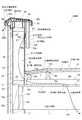
図1において符号1は、建物を示す。この建物1は、屋上部10の外周部11に立設されるとともに、上端部に笠木30が取り付けられた立ち上がり部20を有する。
また、符号2は、前記建物1の屋内空間を示す。屋内空間2は、建物内に設けられる部屋や小屋裏(天井裏)等の空間を指している。
また、符号3は、屋外空間である外部のうち、特に前記笠木30付近を指す。また、前記笠木30付近のうちでも、特に、後述する笠木通気部品40の通気孔42付近を指すものとする。In FIG. 1,
Reference numeral 2 denotes an indoor space of the
前記屋上部10は、例えば陸屋根やルーフバルコニーの床部等のようなフラットに近い床面を有する。なお、この床面には水勾配が形成されており、前記屋上部10に降り注いだ雨水等を、図示しない排水設備から外部へと排水することができる。
また、前記床面には防水シート15が貼設されている。また、この防水シート15は、前記立ち上がり部20を構成する本体壁部21に対しても連続的に貼設されている。つまり、前記防水シート15は、前記本体壁部21の屋上部側面から、該本体壁部21の上端面を介して、該本体壁部21の外部側面の上端部にわたって貼設されている。これによって、前記外周部11と前記立ち上がり部20との接続箇所や、前記本体壁部21の上端部の周囲からの雨水の浸入を防いでいる。The rooftop 10 has a substantially flat floor surface such as a flat roof or a floor of a roof balcony. Note that a water gradient is formed on the floor surface, and rainwater or the like poured on the rooftop 10 can be drained from a drainage facility (not shown) to the outside.
A
そして、前記屋上部10は、前記建物1の屋内空間2の上方に配置されている。また、該屋上部10は、該屋上部10の上面側および下面側に離間して配置される面材12,13aと、これら上下の面材12,13a間に形成された屋根裏空間部14と、を備える。 The rooftop 10 is disposed above the indoor space 2 of the
前記面材13aは、屋内空間2を構成する外壁パネル17の上端部に設置される床パネル13を構成している。また、この面材13aは、水平に配置されている。
前記床パネル13は、縦横の框材13bが矩形状に組み立てられるとともに、この矩形枠の内部に補助桟材13cが縦横に組み付けられて枠体が構成され、この枠体の上面に前記面材13aが貼設されたものである。
また、前記床パネル13は、胴差13dとともに前記外壁パネル17の上端部に載置されている。The
The
The
前記面材12は、前記屋上部10の床面を構成するものであり、図1に示すように、前記床パネル13の上面に設置される支持部16上に設置されている。
前記支持部16は、添え板16aと、第一支持桟材16bと、第二支持桟材16cと、第三支持桟材16dとを有する。
前記添え板16aは、前記本体壁部21と前記床パネル13の面材13aとの境界部分に、前記本体壁部21の屋上部10側の側面下端部に沿って取り付けられている。また、該添え板16aは、後述する第一通気孔部A1を避けて設けられる。
前記第一支持桟材16bは、前記床パネル13の面材13aの上面に、間隔をあけて複数設置されている。
前記第二支持桟材16cは、前記複数の第一支持桟材16bに対して直交するようにして、該複数の第一支持桟材16b上に複数設置されている。
前記第三支持桟材16dは、前記添え板16aに当接するとともに、前記複数の第一支持桟材16bに対して直交するようにして、該複数の第一支持桟材16b上に設置されている。また、前記第三支持桟材16dは、前記第二支持桟材16cよりも高さが低く形成されている。
なお、前記添え板16aは、その高さが、前記第三支持桟材16dの上端部よりも高くなるように設定されている。The
The
The
A plurality of the first support bars 16b are installed on the upper surface of the
A plurality of the second support bars 16c are installed on the plurality of first support bars 16b so as to be orthogonal to the plurality of first support bars 16b.
The
In addition, the said
また、前記面材12は、上板12aと、下板12bとを上下二枚重ねすることにより構成されている。そして、この面材12は、前記支持部16の前記添え板16a、前記第二支持桟材16cおよび前記第三支持桟材16d上に設置されている。
前記第三支持桟材16dが前記第二支持桟材16cよりも低くなっている。このため、前記面材12は、前記第三支持桟材16dの最も近くに位置する前記第二支持桟材16cの位置から下方に傾斜するように形成されている。
さらに、前記面材12は、前記下板12bが前記上板12aよりも短く形成されることによって、前記本体壁部21側の端部に凹部12cが形成された状態となっている。そして、この凹部12cに前記添え板16aの上端部が嵌合されている。
換言すれば、前記上板12aが、前記下板12bよりも前記本体壁部21側に長く形成され、前記添え板16aの上端部に載置されている。Moreover, the said
The third
Furthermore, the
In other words, the
前記屋根裏空間部14は、上述のように前記上下の面材12,13a間に形成されている。すなわち、この屋根裏空間部14は、前記床パネル13と前記面材12の下面との間の、前記支持部16を含む空間部を指している。 The
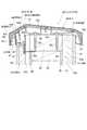
前記立ち上がり部20は、上述のように、上端部に笠木30が取り付けられるものである。また、この立ち上がり部20は、内部中空部22を有する前記本体壁部21と、前記本体壁部21の外部側面と屋上部側面に第一隙間S1をあけて取り付けられる複数の外装材23,23と、を備える。
また、前記立ち上がり部20は、前記本体壁部21の上端部に、該本体壁部21の長さ方向に沿って取り付けられる調整材28を、さらに備える。As described above, the rising portion 20 has the
The rising portion 20 further includes an
前記本体壁部21は、壁パネルであり、縦框材24と横框材25が矩形状に組み立てられるとともに、この矩形枠の内部に補助桟材(図示せず)が組み付けられて枠体が構成され、この枠体の両側面に側面材26,26が貼設されたものである。
そして、前記縦框材24と、前記横框材25と、前記両側面材26,26とによって囲まれた部分が前記内部中空部22とされている。
また、前記本体壁部21は、前記外壁パネル17の上方に位置しており、該本体壁部21と外壁パネル17との間に前記床パネル13および前記胴差13dが介在している。The main body wall portion 21 is a wall panel. The
A portion surrounded by the
The main body wall 21 is located above the
前記調整材28はいわゆる角材であり、図1および図2に示すように、前記本体壁部21の厚みと同等の幅寸法に設定されている。また、この調整材28の高さは、前記笠木30固定用のビス32a,32aを、十分にねじ込ませることができる程度に設定されている。 The
前記外装材23,23は、胴縁23a,23aを介して前記本体壁部21の外部側面と屋上部側面とに取り付けられている。なお、前記胴縁23aは縦胴縁であり、前記本体壁部21の外部側面および屋上部側面の幅方向に間隔をあけて複数取り付けられているものとする。
前記屋上部10に面して取り付けられる一方の前記外装材23は、前記調整材28と前記本体壁部21の上端部から、該本体壁部21の中央付近までの長さに設定されている。
前記外部に面して取り付けられる他方の前記外装材23は、前記調整材28の上端部よりも下方で、かつ前記本体壁部21の上端部から、前記胴差13dを介して、前記外壁パネル17にわたる長さに設定されている。
前記他方の外装材23の上端部は、前記一方の外装材23の上端部よりも低い位置に配置された状態となっている。つまり、前記他方の外装材23の上端部の上方には、前記一方の外装材23の上端部の上方よりも、広いスペースを確保できるようになっている。そして、このようなスペースを利用して、後述する笠木通気部品40が取り付けられることになる。
さらに、前記外装材23,23のそれぞれの表面には、複数の縦溝23bが形成されている。The
One of the
The other
The upper end portion of the
Furthermore, a plurality of
前記第一隙間S1は、上述のように前記本体壁部21の外部側面および屋上部側面と、前記外装材23,23との間に形成されている。また、前記外装材23,23は、前記胴縁23a,23aを介して前記本体壁部21の外部側面と屋上部側面とに取り付けられる。このため、これら胴縁23a,23aの長さおよび厚みと、隣り合う胴縁23a,23a間の長さとで規定される空間が、前記第一隙間S1とされている。As described above,the first gap S <b> 1 is formed between the outer side surface and the rooftop side surface of the main body wall portion 21 and the
前記笠木30は、長さ方向において同一断面となる金属製の長尺物であり、図1,図2に示すように、上面部30aと、この上面部30aの外部側端部および屋上部側端部から下方に垂設される側面部30b,30bとを備える。
前記上面部30aは、側面視において、複数の折曲部を有するように、かつ緩やかに折曲加工された状態となっている。また、裏面にはフック状の係合部が形成されている。
前記側面部30b,30bは、略鉛直に配置された状態となっている。また、前記屋上部10側に位置する側面部30bの下端部と、前記他方の外装材23との間には、弾性を有する防水部材34が設けられている。The
The
The
また、前記笠木30は、前記本体壁部21の上端部に、この本体壁部21の上面および前記外装材23,23の上端部との間に第二隙間S2をあけて取り付けられている。
より詳細には、前記本体壁部21の上端部に取り付けられた前記調整材28の上面に、前記笠木30を支持する支持部材32が、該調整材の長さ方向に間隔をあけて複数設けられている。なお、前記支持部材32は、ビス32a,32aによって前記調整材28に固定されている。そして、前記笠木30は、前記複数の支持部材32間に架設されている。
また、前記支持部材32は、前記フック状の被係合部を備える。したがって、前記笠木30は、前記支持部材32に対して、前記係合部を前記被係合部に係合させることにより取り付けられている。Further, the
More specifically, a plurality of
The
また、前記笠木30は、前記本体壁部21の上端部および前記調整材28の長さ方向に沿って連続的に複数設けられているものとする。
また、隣接する笠木30,30の長さ方向側端部同士は、図2に示すように、内継手であるジョイナー33によって連結されている。また、このジョイナー33は、ネジ33aによって前記支持部材32に固定されている。Further, a plurality of the
Moreover, the length direction side edge parts of the
前記第二隙間S2は、上述のように前記笠木30と、前記本体壁部21の上面および前記外装材23,23の上端部との間に形成されている。より詳細には、前記笠木30の上面部30aの裏側(下方)と、前記本体壁部21上に設けられた前記調整材28および前記外装材23,23の上端部との間に形成されているものとする。
また、前記第二隙間S2のうち、前記他方の外装材23側の第二隙間S2は、上述のように前記他方の外装材23の上端部が、前記一方の外装材23の上端部よりも低い位置に配置された分、前記一方の外装材23側の第二隙間S2よりも広く形成されている。
そして、前記第一隙間S1と前記第二隙間S2は、図1,図2に示すように、互いに連通した状態となっている。As described above,the second gap S <b> 2 is formed between the
Further, among thesecond gap S2,the second gap S2 of the other of the
The first gap S1 andthe second gap S2 are in communication with each other as shown in FIGS.
また、前記屋内空間2と前記笠木30の外部3との間には、図1,図2に示すように、前記屋根裏空間部14と、前記内部中空部22と、前記互いに連通する第一隙間S1及び第二隙間S2とを経由する通気経路Kが形成されている。なお、この通気経路Kは、図1において破線両方向矢印で示されている。
さらに、前記通気経路K上には、笠木通気部品40と、壁通気部品50とが設けられるとともに、前記第一通気孔部A1と、第二通気孔部A2とが形成される。Further, as shown in FIGS. 1 and 2, the
Further, the
前記笠木通気部品40は、図1,図2に示すように、前記互いに連通する第一隙間S1及び第二隙間S2と前記笠木30の外部3とを通気可能に連通するものである。そして、前記互いに連通する隙間S1,S2と前記外部3との境界部分に、前記笠木30の裏面と離間するようにして設けられている。
なお、上述のように、前記第二隙間S2のうち、前記他方の外装材23側の第二隙間S2は、前記一方の外装材23側の第二隙間S2よりも広く形成されている。このため、前記笠木通気部品40は、前記他方の外装材23側の第二隙間S2に位置するようにして設けられている。The coping
As described above, among thesecond gap S2,the second gap S2 of the other of the
また、前記笠木通気部品40は、前記笠木30の長さ方向に沿って長尺に形成されたものであり、正面板部41と、水切り壁43と、閉塞部44とを備える。また、この笠木通気部品40は、一枚の金属板を適宜折曲加工することによって形成されている。
前記正面板部41は、前記笠木30の外部3に面して配置されるとともに、長さ方向に複数の通気孔42が並設されている。
前記水切り壁43は、前記正面板部41と対向するとともに該正面板部41よりも前記第一隙間S1及び第二隙間S2側に配置されている。
前記閉塞部44は、前記笠木通気部品40と前記笠木30の裏面との間に設けられたものである。The
The
The draining
The closing
前記正面板部41は、図2に示すように、前記笠木30の前記側面部30bと対向するとともに、鉛直よりも外部3側に傾いた状態で配置されている。
また、前記正面板部41と前記側面部30bとの間の空間は、上方に向かうにつれて狭まるように形成されている。As shown in FIG. 2, the
Further, the space between the
前記通気孔42は、第一開口部42aと、遮蔽壁42bと、第二開口部42c,42cとを備える。
前記第一開口部42aは、外部3側に面する開口である。
前記遮蔽壁42bは、前記第一開口部42aに対して前記第一隙間S1及び第二隙間S2側に後退した位置で対向配置されている。
前記第二開口部42c,42cは、前記第一開口部42aおよび前記遮蔽壁42bの左右両側にそれぞれ開口している。
なお、本実施の形態の通気孔42は、前記正面板部41を、パンチング技術等を採用して適宜加工することによって形成されている。
このような形状の通気孔42によれば、前記通気孔42から前記通気経路K内へと吹き込もうとする空気は、前記第一開口部42aから入った直後に、まず前記遮蔽壁42bに当たり、その後、前記第二開口部42c,42c左右に別れてから前記笠木通気部品40の内側に至ることになる。したがって、前記通気経路K側に空気を吹き込ませつつ、前記通気経路K内への雨水の浸入を効率良く防ぐことができる。The
The
The shielding
The
The
According to the
前記水切り壁43は、上述のように、前記正面板部41と対向するとともに該正面板部41よりも前記第一隙間S1及び第二隙間S2側に配置されている。これによって、前記通気孔42から雨水が浸入した場合に、この水切り壁43によって、雨水が前記第二隙間S2のさらに奥に浸入することを防ぐことができる。
なお、前記水切り壁43は、後述する対向板部44aのうち、前記正面板部41とは反対側の端部に一体形成されている。The draining
In addition, the said draining
前記閉塞部44は、対向板部44aと、弾性部材44bとを備える。
前記対向板部44aは、前記正面板部41の上端部に一体形成されるとともに前記笠木30の裏面に対向する。より詳細には、この対向板部44aは、前記笠木30の上面部30aの裏面に対向した状態となっている。
前記弾性部材44bは、前記対向板部44aの笠木側面に、該対向板部44aの長さ方向にわたって取り付けられるとともに、前記笠木30が押し付けられることによって弾性変形するものである。より詳細には、この弾性部材44bは、前記対向板部44aの上面と、前記笠木30の上面部30aの裏面との間に設けられる。また、この弾性部材44bは、弾性変形する以前は、前記笠木30の裏面と前記対向板部44aとの間の隙間よりも厚みがある状態とされている。そして、前記笠木30の取り付け時に、該笠木30の押し付けによって、つぶれるように弾性変形する設定となっている。
このような閉塞部44によれば、前記対向板部44aの笠木側面に取り付けられた前記弾性部材44bは、前記笠木30が押し付けられることによって弾性変形するので、前記笠木30の裏面に対して密接されることになる。これによって、前記閉塞部44によって前記第一隙間S1及び前記第二隙間S2側への雨水の浸入を確実に防ぐことができる。
なお、前記弾性部材44bとしては、例えばEPDM発泡体等のような、弾力性能および防水性能を有するものが採用されている。The closing
The facing
The
According to such a
As the
さらに、前記笠木通気部品40は、固定板部45と、突出板部46と、防水部材47とを備える。
前記固定板部45は、前記胴縁23aを介して前記本体壁部21に、釘45a等の止着材によって固定される板状部である。また、この固定板部45の上端部には、該上端部を前記正面板部41側に折曲加工してなる水切り部45bが形成されている。このような水切り部45bによれば、雨水のさらなる浸入を防ぐことができる。
前記突出板部46は、前記固定板部45と一体形成されるとともに該固定板部45の中央部から外部3に向かって突出する板状部である。また、この突出板部46は、前記他方の外装材23の上方に配置されている。さらに、この突出板部46の突出方向先端部は、前記正面板部41の下端部と一体形成されている。
前記防水部材47は、前記固定板部45の下部と前記他方の外装材23の上端部との間に挟み込まれるものであり、これら固定板部45と他方の外装材23との間の隙間の防水が可能となっている。Further, the
The fixing
The protruding
The
前記固定板部45は、上述のように、前記胴縁23aを介して前記本体壁部21に固定されるものである。
また、前記胴縁23aは、図2,図7,図8に示すように、前記固定板部45の幅方向に点在するようにして配置されている。すなわち、当該胴縁23aは、前記本体壁部21の外部側面の上端部の左右方向に、互いに間隔を空けて複数設けられている。
なお、前記胴縁23aは、前記固定板部45の上下方向の長さと略等しい長さであってもよいし、前記外装材23の上下方向の長さに合わせて長尺に形成されていてもよい。さらには、長尺な胴縁23aを、前記固定板部45の部分と前記外装材23の部分とに分けてもよいものとする。As described above, the fixing
Further, as shown in FIGS. 2, 7, and 8, the
The
また、前記固定板部45は、図2に示すように、前記本体壁部21に対し、前記釘45aによって、当該釘45aが前記胴縁23aを貫通して前記本体壁部21に打ち込まれることによって固定されている。
前記固定板部45には、図7に示すように、予め釘45a等の止着材が挿通される孔部45cが形成されている。そして、当該孔部45cの位置と前記胴縁23aの位置とが対応している。In addition, as shown in FIG. 2, the fixing
As shown in FIG. 7, the fixing
以上のように前記固定板部45は、前記本体壁部21に対し、前記釘45aによって、当該釘45aが前記胴縁23aを貫通して前記本体壁部21に打ち込まれることによって固定されるので、前記釘45aによって前記固定板部45と前記胴縁23aとを前記本体壁部21に確実に取り付けることができる。
また、前記胴縁23aは、前記固定板部45の幅方向に点在するようにして配置されるので、隣り合う前記胴縁23a,23a間を通気口として使用することができる。これによって、前記本体壁部21と前記複数の外装材23との第一隙間S1を確保しつつ、当該第一隙間S1における通気性を向上できる。As described above, the fixing
Moreover, since the said
また、前記固定板部45は、上述のように、当該固定板部45の上端部を前記正面板部41側に折曲加工してなる前記水切り部45bを有する。なお、この水切り部45bの角度は空気の流通を阻害しない程度に設定されている。
このような水切り部45bによれば、前記笠木通気部品40内を吹き上がる風に混ざる雨水を捉えることができ、さらに、付着した雨水を下方へと垂らすことができる。これによって、前記笠木通気部品40内における防水性をより向上できる。Moreover, the said fixed
According to such a
前記突出板部46は、上述のように、前記固定板部45の中央部から外部3に向かって突出するものである。
また、前記突出板部46の一端部は前記固定板部45と一体形成され、他端部は前記正面板部41と一体形成され、当該突出板部46は、前記一端部から前記他端部に向かって下り勾配となっている。すなわち、当該突出板部46は、水勾配を形成するようにして前記正面板部41と前記固定板部45との間に設けられている。
これによって、例えば正面板部41を越えて浸入してきた雨水が前記突出板部46に付着した場合に、前記本体壁部21側に流れずに、前記外部3側に流れることになるので、前記笠木通気部品40内部における防水性をより向上できる。The protruding
Further, one end of the protruding
Thereby, for example, when rainwater that has entered beyond the
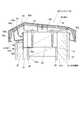
前記壁通気部品50は、図1,図3に示すように、前記本体壁部21の側面材26に取り付けられている。
より詳細には、前記本体壁部21の前記両側面材26,26のうち少なくとも一方の側面材26に、前記内部中空部22と前記第一隙間S1とを連通するとともに前記一方の側面材26の幅方向に沿って長尺な貫通孔27が形成されている。そして、この貫通孔27に、前記壁通気部品50が設けられている。
なお、本実施の形態においては、前記両側面材26,26のうち、一方、すなわち前記屋上部10側の側面材26に前記貫通孔27が形成されているものとする。また、この貫通孔27は、前記一方の外装材23によって遮蔽される位置に形成されている。As shown in FIGS. 1 and 3, the
More specifically, the inner
In the present embodiment, it is assumed that the through-
前記壁通気部品50は、前記貫通孔27の長さ方向に沿って長尺に形成された金属製の部品であり、背面板部51と、水切り壁53と、上面板部54と、下面板部55と、固定板部56,56とを有する。 The
前記背面板部51は、前記壁通気部品50が前記貫通孔27に嵌め込まれた際に、前記貫通孔27のうち前記内部中空部22側に配置されるものである。また、この背面板部51には、該背面板部51を厚み方向に貫通する多数の通気孔52…が格子状に並んで形成されている。 The
前記水切り壁53は、前記背面板部51と対向するとともに前記第一隙間S1側に配置されている。また、この水切り壁53の上端部から下端部までの長さは、前記背面板部51の上端部から中央付近まで程度の長さに設定されている。
この水切り壁53によれば、万が一、前記第一隙間S1内に雨水が浸入したとしても、前記水切り壁53によって雨水が前記内部中空部22へと浸入するのを防ぐことができる。The draining
According to the
前記上面板部54は、前記背面板部51の上端部と前記水切り壁53の上端部との間に架設され、かつ一体形成されている。また、この上面板部54は水平に配置されている。
前記下面板部55は、前記背面板部51の下端部と一体形成され、かつ該背面板部51の下端部から斜め下方に傾斜するようにして配置されている。つまり、この下面板部55は、水勾配が形成された状態となるので、万が一、前記第一隙間S1内に雨水が浸入したとしても、雨水が前記内部中空部22へと浸入するのを防ぐことができる。
なお、前記上面板部54および前記下面板部55は、前記壁通気部品50が前記貫通孔27に嵌め込まれた際に、該貫通孔27の上下縁部に当接する部位とされている。The upper
The lower
The upper
前記固定板部56,56のうち、一方の前記固定板部56は、前記水切り壁53と前記上面板部54との交差部と一体形成されるとともに、鉛直上方に配置されている。また、他方の前記固定板部56は、前記下面板部55の下端部と一体形成されるとともに、鉛直下方に配置されている。
これら一方および他方の固定板部56,56は、同一直線上に配置されている。
また、図3(b)に示すように、前記固定板部56を厚み方向に貫通する複数の長孔形状の孔部56a…が、前記固定板部56,56の長さ方向に並んで配置されている。
これら複数の孔部56a…には、前記固定板部56を前記本体壁部21の側面材26に固定するための釘56b等の止着材が挿入される。なお、前記孔部56aが長孔形状に形成されていれば、前記釘56b等によって前記固定板部56を固定した後でも位置調整を行うことができるので好ましい。Of the fixed
These one and other fixing
Further, as shown in FIG. 3 (b), a plurality of long hole-shaped
A fastening material such as a
このような壁通気部品50によれば、前記背面板部51の前記多数の通気孔52…を介して前記内部中空部22と前記第一隙間S1との間で空気を流通させることができる。
また、前記第一隙間S1側に前記水切り壁53が配置されているので、万が一、前記第一隙間S1内に雨水が浸入したとしても、前記水切り壁53によって雨水が前記内部中空部22へと浸入するのを防ぐことができる。つまり、前記笠木通気部品40とともに二重に防水を確保することができるので、全体的な防水性を格段に向上できる。According to such a
In addition, sincethe
また、前記第一通気孔部A1は、前記本体壁部21の前記両側面材26,26のうち前記一方の側面材26の下端部に、該側面材26を厚み方向に貫通するようにして形成されている。そして、この第一通気孔部A1によって、前記屋根裏空間部14と前記内部中空部22とが連通されている。
前記第二通気孔部A2は、前記屋上部10の下面側の面材13aに、該面材13aを厚み方向に貫通するようにして形成されている。そして、この第二通気孔部A2によって、前記屋内空間2と前記屋根裏空間部14とが連通されている。
このような第一通気孔部A1および第二通気孔部A2によれば、前記屋内空間2と前記笠木30の外部3との間に、前記屋根裏空間部14と、前記内部中空部22と、前記互いに連通する第一隙間及び第二隙間S2とを経由する通気経路Kを確保できる。Further, the first vent hole A1 is formed so as to penetrate through the
The second vent hole portion A2 is formed in the
According to the first vent hole portion A1 and the second vent hole portion A2, the
次に、前記通気経路Kを通過する空気の流れについて説明する。
前記外部3から前記笠木通気部品40の前記正面板部41へと流れてきた空気は、前記通気孔42の前記第一開口部42aから内部へと流入する。この場合、前記笠木30付近が空気の導入側となる。
この時、前記遮蔽壁42bおよび前記第二開口部42c,42cにより空気は二手に分かれながら、前記笠木通気部品40の内部へと流入する。
前記笠木通気部品40の内部へと流入し、合流した空気は、前記水切り壁43と前記固定板部45の水切り部45bとを避けるようにしながら、前記笠木30の裏面と前記調整材28の上面との間を通過していく。
続いて、空気は、前記本体壁部21と前記一方の外装材23と間の前記第一隙間S1とを下降し、前記壁通気部品50の前記多数の通気孔52…を通過して、前記本体壁部21の内部中空部22へと流入する。
続いて、空気は、前記第一通気孔部A1を通過して、前記屋根裏空間部14へと流入する。そして、この屋根裏空間部14に流入した空気は、前記第二通気孔部A2を通過して、前記屋内空間2へと流入することになる。Next, the flow of air passing through the ventilation path K will be described.
Air that has flowed from the outside 3 to the
At this time, air flows into the
The air that flows into and joins the
Subsequently, the air descends throughthe first gap S1 between the main body wall portion 21 and the one
Subsequently, the air passes through the first vent hole A <b> 1 and flows into the
なお、以上のような空気の流れは、前記笠木30の外部3から前記屋内空間2へと至るものであるが、これに限られず、例えば図1の破線両方向矢印で示すように、前記屋内空間2から前記外部3へと至る空気の流れであってもよい。この場合、前記笠木30付近が空気の排出側となる。
また、このように空気を、前記通気経路K上を移動させる際に、暖められた空気が上昇する性質や、冷たい空気が下降する性質、煙突効果等を利用してもよいものとする。Note that the air flow as described above extends from the
In addition, when air is moved on the ventilation path K in this way, the property that warmed air rises, the property that cold air descends, the chimney effect, and the like may be used.
なお、本実施の形態において、前記壁通気部品50の取付位置は、前記一方の側面材26に形成された貫通孔27としたが、これに限られるものではない。すなわち、例えば図4に示すように、前記壁通気部品50の取付位置を、前記本体壁部21の前記他方の側面材26に形成された貫通孔27に変更してもよい。
この場合、前記笠木通気部品40の内部へと流入した空気は、前記水切り壁43と前記固定板部45の水切り部45bとを避けるようにしながら、前記本体壁部21と前記他方の外装材23と間の前記第一隙間S1とを下降する。さらに、前記壁通気部品50の前記多数の通気孔52…を通過して、前記本体壁部21の内部中空部22へと流入する。
なお、その後の空気の流れは、上述のものと同様である。また、上述の例と同様に、空気の流れを反対にしてもよいし、空気の性質等を利用してもよいものとする。In the present embodiment, the mounting position of the
In this case, the air that has flowed into the
The subsequent air flow is the same as described above. Further, similarly to the above-described example, the air flow may be reversed, or the nature of air may be used.
また、本実施の形態において、前記笠木通気部品40は、以上のような構成としたが、本発明の趣旨を逸脱しない範囲で適宜変更してもよい。
すなわち、例えば図5に示す笠木通気部品40Aは、正面板部41Aが略鉛直に配置された状態で、前記笠木30の側面部30bと対向するように構成されている。また、この笠木通気部品40Aは、固定板部45Aの上端部に水切り部45bを設けない構成とされている。
また、図6に示す笠木通気部品40Bは、正面板部41Bに形成される通気孔42Bの構成が、前記笠木通気部品40の通気孔42とは異なる。すなわち、前記笠木通気部品40Bの通気孔42Bは、第一開口部42aや遮蔽壁42b、第二開口部42cを備えずに、単に前記正面板部41Bに孔をあけて形成されている。In the present embodiment, the
That is, for example, the
6 is different from the
また、前記固定板部45の下部と前記他方の外装材23の上端部との間の防水を確保するために、上述のように、前記防水部材47を前記固定板部45の下部と前記他方の外装材23の上端部との間に挟み込んでいたが、これに限られるものではない。
すなわち、図6に示すように前記他方の外装材23の上端部と、前記笠木通気部品40Bの突出板部46との間の隙間に、シーリング材48を充填するようにしても良い。シーリング材48は、前記他方の外装材23の上端面と、前記突出板部46に対して水密に密着している。また、バックアップ材48aを下地として充填されている。
なお、このようなシーリング材48およびバックアップ材48aは、前記笠木通気部品40,40Aに採用しても良いものとする。Further, in order to ensure waterproofing between the lower portion of the fixed
That is, as shown in FIG. 6, the sealing
Such a sealing
本実施の形態によれば、前記笠木通気部品40が、前記互いに連通する第一隙間S1及び第二隙間S2と前記笠木30の外部3との境界部分に、前記笠木30と離間するようにして設けられているので、この笠木通気部品40は前記笠木30の裏面側において外部3に近い位置に設けられることになる。また、前記閉塞部44と前記水切り壁43によって前記第一隙間S1及び前記第二隙間S2側への雨水の浸入を防ぐことができるので、前記笠木30付近で防水できることとなり、前記通気経路K内への雨水の浸入を確実に防ぐことができる。
また、前記笠木通気部品40は、前記互いに連通する第一隙間S1及び第二隙間S2と前記笠木30の外部3との境界部分に、前記笠木30と離間するようにして設けられることにより、前記笠木30とは別部材として設けられることになる。したがって、前記笠木30と前記笠木通気部品40のうち、どちらか一方に経年劣化が生じたとしても、双方を同時に交換する必要が無くなるので、例えば前記笠木30と前記笠木通気部品40とが一体に形成される場合に比して、経年劣化対策に係るコストの低減を図ることができる。According to this embodiment, the coping
Furthermore, the coping
1 建物
2 屋内空間
3 外部
10 屋上部
12 面材
13a 面材
14 屋根裏空間部
20 立ち上がり部
21 本体壁部
22 内部中空部
23 外装材
30 笠木
40,40A,40B 笠木通気部品
42 通気孔
43 水切り壁
44 閉塞部
50 壁通気部品DESCRIPTION OF
Claims (8)
Translated fromJapanese前記屋上部は前記建物の屋内空間の上方に配置されており、さらに、この屋上部の上面側および下面側に離間して配置される面材と、これら上下の面材間に形成された屋根裏空間部と、を備えており、
前記立ち上がり部は、内部中空部を有する本体壁部と、前記本体壁部の外部側面と屋上部側面に第一隙間をあけて取り付けられる複数の外装材と、を備えており、
前記笠木は、前記本体壁部の上端部に、この本体壁部の上面および前記外装材の上端部との間に第二隙間をあけて取り付けられており、
前記第一隙間と前記第二隙間は互いに連通しており、
前記屋内空間と前記笠木の外部との間には、前記屋根裏空間部と、前記内部中空部と、前記互いに連通する第一隙間と第二隙間とを経由する通気経路が形成されており、
前記互いに連通する第一隙間と第二隙間と前記笠木の外部との境界部分に、前記互いに連通する第一隙間と第二隙間と前記外部とを通気可能に連通する笠木通気部品が、前記笠木の裏面と離間するようにして設けられており、
前記笠木通気部品は、前記笠木の外部に面して配置されるとともに、長さ方向に複数の通気孔が並設される正面板部と、前記正面板部と対向するとともに該正面板部よりも前記第一隙間及び前記第二隙間側に配置される水切り壁と、前記正面板部の上部と前記笠木の裏面との間に設けられた閉塞部と、胴縁を介して前記本体壁部に固定される固定板部と、を備えており、
前記胴縁は、前記固定板部の幅方向に点在するようにして配置されていることを特徴とする建物の換気構造。In the ventilation structure of a building that has a standing part that is erected on the outer periphery of the rooftop and has a headboard attached to the upper end part,
The rooftop is disposed above the indoor space of the building, and further, a face material disposed separately on the upper surface side and the lower surface side of the rooftop, and an attic formed between the upper and lower surface materials. And a space part,
The rising portion includes a main body wall portion having an internal hollow portion, and a plurality of exterior materials attached to the outer side surface and the rooftop side surface of the main body wall portion with a first gap,
The headboard is attached to the upper end of the main body wall with a second gap between the upper surface of the main body wall and the upper end of the exterior material,
The first gap and the second gap are in communication with each other;
Between the indoor space and the outside of the headboard, a ventilation path is formed through the attic space portion, the internal hollow portion, and the first gap and the second gap communicating with each other,
A headboard ventilation part that allows the first gap, the second gap, and the outside to communicate with each other at a boundary portion between the first gap, the second gap, and the outer side of the headboard that are in communication with each other. It is provided so as to be separated from the back surface of
The headboard ventilation component is arranged to face the outer side of the headboard, and has a front plate portion in which a plurality of ventilation holes are arranged in the length direction, and is opposed to the front plate portion and from the front plate portion. Also, a drain wall disposed on the first gap and the second gap side, a blocking part provided betweenan upper part of the front plate part and the back surface of the headboard, and the main body wall part via a trunk edge And a fixed plate portion fixed to
The ventilation structure of a building, wherein the trunk edges are arranged so as to be scattered in the width direction of the fixed plate portion.
前記通気孔は、外部側に面する第一開口部と、
前記第一開口部に対して前記第一隙間及び前記第二隙間側に後退した位置で対向配置される遮蔽壁と、
前記第一開口部および前記遮蔽壁の左右両側にそれぞれ開口する第二開口部と、を備えることを特徴とする建物の換気構造。The ventilation structure of a building according to claim 1,
The vent is a first opening facing the outside,
A shielding wall disposed opposite to the first opening at a position retracted towardthe first gap and the second gap ;
A ventilation structure for a building, comprising: the first opening and a second opening that opens on each of the left and right sides of the shielding wall.
前記閉塞部は、前記正面板部の上端部に一体形成されるとともに前記笠木の裏面に対向する対向板部と、
前記対向板部の笠木側面に取り付けられるとともに、前記笠木が押し付けられることによって弾性変形する弾性部材と、を備えることを特徴とする建物の換気構造。The building ventilation structure according to claim 1 or 2,
The closing portion is integrally formed at the upper end portion of the front plate portion and is opposed to the back surface of the headboard,
A ventilation structure for a building, comprising: an elastic member that is attached to a side wall of the counter plate portion and elastically deforms when the cap is pressed.
前記固定板部は、前記本体壁部に対し、釘等の止着材によって、当該止着材が前記胴縁を貫通して前記本体壁部に打ち込まれることによって固定されていることを特徴とする建物の換気構造。In the ventilation structure of the building as described in any one of Claims 1-3,
Prior Symbol fixing plate portion, with respect to the body wall portion, characterized in that the fastening member such as a nail, and is fixed by the fastening member is driven into the body wall portion through said furring strips The ventilation structure of the building.
前記笠木通気部品は、前記固定板部から外部に向かって突出する突出板部を備えており、
前記突出板部の一端部は前記固定板部と一体形成され、他端部は前記正面板部と一体形成され、当該突出板部は、前記一端部から前記他端部に向かって下り勾配となっていることを特徴とする建物の換気構造。The ventilated building structure according toany one of claims1-4,
The headboard ventilation component includes a protruding plate portion protruding outward from the fixed plate portion,
One end portion of the protruding plate portion is formed integrally with the fixed plate portion, the other end portion is formed integrally with the front plate portion, and the protruding plate portion is inclined downward from the one end portion toward the other end portion. Ventilation structure of a building, characterized by
前記固定板部は、当該固定板部の上端部を前記正面板部側に折曲加工してなる水切り部を有することを特徴とする建物の換気構造。The ventilated building structure according toany one of claims1 to 5
The said fixed board part has the draining part formed by bending the upper end part of the said fixed board part to the said front board part side, The ventilation structure of the building characterized by the above-mentioned.
前記本体壁部は、縦横の框材が矩形枠状に組み立てられて構成された矩形枠体の両側に側面材が取り付けられてなり、
前記両側面材のうち少なくとも一方の側面材には、前記内部中空部と前記第一隙間とを連通するとともに前記一方の側面材の幅方向に沿って長尺な貫通孔が形成されており、
前記貫通孔には、この貫通孔の長さ方向に沿って長尺な壁通気部品が設けられており、
前記壁通気部品は、前記貫通孔のうち前記内部中空部側に配置されるとともに多数の通気孔が形成される背面板部と、この背面板部と対向するとともに前記第一隙間側に配置される水切り壁と、を有することを特徴とする建物の換気構造。In the building ventilation structure according to any one of claims 1 to 6,
The main body wall is formed by attaching side members on both sides of a rectangular frame formed by assembling vertical and horizontal saddles into a rectangular frame shape,
At least one side member among the two side members has a long through-hole formed along the width direction of the one side member while communicating the internal hollow portion andthe first gap.
The through-hole is provided with a long wall ventilation component along the length direction of the through-hole,
The wall ventilation component is disposed on the inner hollow portion side of the through-hole and a back plate portion on which a large number of ventilation holes are formed, and is disposed onthe first gap side while facing the back plate portion. A ventilation structure for a building, characterized by having a draining wall.
前記本体壁部の前記両側面材のうち屋上部側の側面材の下端部には、前記屋根裏空間部と前記内部中空部とを連通する第一通気孔部が形成されており、
前記屋上部の下面側の面材には、前記屋内空間と前記屋根裏空間部とを連通する第二通気孔部が形成されていることを特徴とする建物の換気構造。In the ventilation structure of the building as described in any one of Claims 1-7,
A first vent hole portion that connects the attic space portion and the internal hollow portion is formed at the lower end portion of the side material on the rooftop side of the both side surface materials of the main body wall portion,
A ventilation structure for a building, characterized in that a second ventilation hole portion that communicates the indoor space and the attic space portion is formed in the face material on the lower surface side of the rooftop.
Priority Applications (1)
| Application Number | Priority Date | Filing Date | Title |
|---|---|---|---|
| JP2013145106AJP6205197B2 (en) | 2012-07-11 | 2013-07-11 | Building ventilation structure |
Applications Claiming Priority (3)
| Application Number | Priority Date | Filing Date | Title |
|---|---|---|---|
| JP2012155240 | 2012-07-11 | ||
| JP2012155240 | 2012-07-11 | ||
| JP2013145106AJP6205197B2 (en) | 2012-07-11 | 2013-07-11 | Building ventilation structure |
Related Child Applications (1)
| Application Number | Title | Priority Date | Filing Date |
|---|---|---|---|
| JP2016053218ADivisionJP6208795B2 (en) | 2012-07-11 | 2016-03-17 | Kasagi ventilation parts |
Publications (2)
| Publication Number | Publication Date |
|---|---|
| JP2014031709A JP2014031709A (en) | 2014-02-20 |
| JP6205197B2true JP6205197B2 (en) | 2017-09-27 |
Family
ID=50281742
Family Applications (2)
| Application Number | Title | Priority Date | Filing Date |
|---|---|---|---|
| JP2013145106AActiveJP6205197B2 (en) | 2012-07-11 | 2013-07-11 | Building ventilation structure |
| JP2016053218AActiveJP6208795B2 (en) | 2012-07-11 | 2016-03-17 | Kasagi ventilation parts |
Family Applications After (1)
| Application Number | Title | Priority Date | Filing Date |
|---|---|---|---|
| JP2016053218AActiveJP6208795B2 (en) | 2012-07-11 | 2016-03-17 | Kasagi ventilation parts |
Country Status (1)
| Country | Link |
|---|---|
| JP (2) | JP6205197B2 (en) |
Families Citing this family (10)
| Publication number | Priority date | Publication date | Assignee | Title |
|---|---|---|---|---|
| JP6198330B2 (en)* | 2014-03-26 | 2017-09-20 | 倉敷紡績株式会社 | Ventilation structure of building |
| JP6235976B2 (en)* | 2014-09-30 | 2017-11-22 | 大和ハウス工業株式会社 | Kasagi installation structure |
| JP6235977B2 (en)* | 2014-09-30 | 2017-11-22 | 大和ハウス工業株式会社 | Kasagi and Kasagi installation structure |
| JP6205338B2 (en)* | 2014-11-11 | 2017-09-27 | 株式会社トーコー | Parapet ventilation |
| JP6797530B2 (en)* | 2016-01-29 | 2020-12-09 | ケイミュー株式会社 | Parapet ventilation structure and ventilation fittings |
| JP7012333B2 (en)* | 2017-04-24 | 2022-01-28 | 株式会社ハウゼコ | Balcony ventilation structure and its installation method |
| JP7433142B2 (en)* | 2020-06-16 | 2024-02-19 | 旭化成ホームズ株式会社 | Wall structure and building |
| JP7279950B2 (en)* | 2020-12-04 | 2023-05-23 | 株式会社トーコー | Ventilation system for top rail |
| JP7149673B1 (en) | 2022-05-10 | 2022-10-07 | 株式会社ハウゼコ | ventilation structure |
| JP7708232B1 (en) | 2024-01-24 | 2025-07-15 | 積水ハウス株式会社 | building |
Family Cites Families (12)
| Publication number | Priority date | Publication date | Assignee | Title |
|---|---|---|---|---|
| JPS6041185B2 (en)* | 1980-10-15 | 1985-09-14 | 積水ハウス株式会社 | Flat roof ventilation structure |
| JP3408605B2 (en)* | 1993-12-20 | 2003-05-19 | ミサワホーム株式会社 | Ventilation structure of roof without snowfall |
| JPH1181507A (en)* | 1997-09-12 | 1999-03-26 | Kubota House Corp | Building ventilation equipment |
| JPH11140998A (en)* | 1997-11-10 | 1999-05-25 | Sekisui House Ltd | Wall ventilation structure |
| JP4447097B2 (en)* | 1999-12-22 | 2010-04-07 | 文化シヤッター株式会社 | Structure gap closing structure cover |
| JP4478433B2 (en)* | 2003-11-06 | 2010-06-09 | ミサワホーム株式会社 | Ventilation structure of building |
| JP2007092323A (en)* | 2005-09-27 | 2007-04-12 | Kaneka Corp | Roof structure with venting skin and building having roof structure with venting skin |
| JP2008190234A (en)* | 2007-02-06 | 2008-08-21 | Misawa Homes Co Ltd | Attic space ventilation structure and method of forming attic space ventilation structure |
| JP5424040B2 (en)* | 2009-12-18 | 2014-02-26 | 積水ハウス株式会社 | Attic ventilation structure |
| JP2012007433A (en)* | 2010-06-28 | 2012-01-12 | Nippon Jukankyo Kk | Ventilation structure at wall body structure section of house |
| JP5774840B2 (en)* | 2010-11-08 | 2015-09-09 | 株式会社トーコー | Parapet ventilation structure |
| JP5679784B2 (en)* | 2010-11-29 | 2015-03-04 | 日本住環境株式会社 | Ventilation structure in the wall structure of a house |
- 2013
- 2013-07-11JPJP2013145106Apatent/JP6205197B2/enactiveActive
- 2016
- 2016-03-17JPJP2016053218Apatent/JP6208795B2/enactiveActive
Also Published As
| Publication number | Publication date |
|---|---|
| JP6208795B2 (en) | 2017-10-04 |
| JP2014031709A (en) | 2014-02-20 |
| JP2016130451A (en) | 2016-07-21 |
Similar Documents
| Publication | Publication Date | Title |
|---|---|---|
| JP6205197B2 (en) | Building ventilation structure | |
| US20130291465A1 (en) | Vented wall girts | |
| JP6261172B2 (en) | Eaves ventilation | |
| JP2010095956A (en) | External heat insulating panel and external heat insulating structure | |
| KR200370381Y1 (en) | Sandwiches panel for roof construction | |
| JP6797530B2 (en) | Parapet ventilation structure and ventilation fittings | |
| JP5457862B2 (en) | Venting material and exterior wall structure of buildings | |
| JP5775035B2 (en) | Roof structure | |
| JP6882927B2 (en) | Ventilation member end cap and outer wall structure | |
| JP4183085B2 (en) | Eaves structure with ventilation function | |
| JP5424040B2 (en) | Attic ventilation structure | |
| US9051732B2 (en) | Intermediate divider within an exterior wall unit | |
| JP2008082034A (en) | Ventilating ridge structure and ventilating roof structure | |
| JP4869639B2 (en) | Drainage member and building ventilation structure | |
| EP3999691A1 (en) | Ventilation member and wall material construction structure | |
| JP7323415B2 (en) | entrance porch | |
| JP7069083B2 (en) | Kasagi drainage structure | |
| JP2012233340A (en) | Outer wall structure | |
| JP3501224B2 (en) | Exterior wall construction structure | |
| JP5674144B2 (en) | Ventilation tower structure | |
| JP7296307B2 (en) | Decorative material | |
| JP5898414B2 (en) | Building outer wall structure | |
| JP2022163903A (en) | Vented seal material and vented seal structure | |
| JP4313735B2 (en) | Exterior wall mounting structure | |
| JP2024088936A (en) | Building materials and construction methods |
Legal Events
| Date | Code | Title | Description |
|---|---|---|---|
| A621 | Written request for application examination | Free format text:JAPANESE INTERMEDIATE CODE: A621 Effective date:20160225 | |
| A977 | Report on retrieval | Free format text:JAPANESE INTERMEDIATE CODE: A971007 Effective date:20161128 | |
| A131 | Notification of reasons for refusal | Free format text:JAPANESE INTERMEDIATE CODE: A131 Effective date:20161213 | |
| A521 | Request for written amendment filed | Free format text:JAPANESE INTERMEDIATE CODE: A523 Effective date:20170213 | |
| A131 | Notification of reasons for refusal | Free format text:JAPANESE INTERMEDIATE CODE: A131 Effective date:20170620 | |
| A521 | Request for written amendment filed | Free format text:JAPANESE INTERMEDIATE CODE: A523 Effective date:20170815 | |
| TRDD | Decision of grant or rejection written | ||
| A01 | Written decision to grant a patent or to grant a registration (utility model) | Free format text:JAPANESE INTERMEDIATE CODE: A01 Effective date:20170829 | |
| A61 | First payment of annual fees (during grant procedure) | Free format text:JAPANESE INTERMEDIATE CODE: A61 Effective date:20170904 | |
| R150 | Certificate of patent or registration of utility model | Ref document number:6205197 Country of ref document:JP Free format text:JAPANESE INTERMEDIATE CODE: R150 | |
| R250 | Receipt of annual fees | Free format text:JAPANESE INTERMEDIATE CODE: R250 | |
| R250 | Receipt of annual fees | Free format text:JAPANESE INTERMEDIATE CODE: R250 |