JP6204800B2 - COMMUNICATION DEVICE, COMMUNICATION DEVICE CONTROL METHOD, AND PROGRAM - Google Patents
COMMUNICATION DEVICE, COMMUNICATION DEVICE CONTROL METHOD, AND PROGRAMDownload PDFInfo
- Publication number
- JP6204800B2 JP6204800B2JP2013238268AJP2013238268AJP6204800B2JP 6204800 B2JP6204800 B2JP 6204800B2JP 2013238268 AJP2013238268 AJP 2013238268AJP 2013238268 AJP2013238268 AJP 2013238268AJP 6204800 B2JP6204800 B2JP 6204800B2
- Authority
- JP
- Japan
- Prior art keywords
- communication device
- communication
- address
- service
- data
- Prior art date
- Legal status (The legal status is an assumption and is not a legal conclusion. Google has not performed a legal analysis and makes no representation as to the accuracy of the status listed.)
- Active
Links
Images


Classifications
- H—ELECTRICITY
- H04—ELECTRIC COMMUNICATION TECHNIQUE
- H04L—TRANSMISSION OF DIGITAL INFORMATION, e.g. TELEGRAPHIC COMMUNICATION
- H04L41/00—Arrangements for maintenance, administration or management of data switching networks, e.g. of packet switching networks
- H04L41/08—Configuration management of networks or network elements
- H04L41/0803—Configuration setting
- H04L41/0806—Configuration setting for initial configuration or provisioning, e.g. plug-and-play
- H—ELECTRICITY
- H04—ELECTRIC COMMUNICATION TECHNIQUE
- H04N—PICTORIAL COMMUNICATION, e.g. TELEVISION
- H04N1/00—Scanning, transmission or reproduction of documents or the like, e.g. facsimile transmission; Details thereof
- H04N1/00127—Connection or combination of a still picture apparatus with another apparatus, e.g. for storage, processing or transmission of still picture signals or of information associated with a still picture
- H04N1/00204—Connection or combination of a still picture apparatus with another apparatus, e.g. for storage, processing or transmission of still picture signals or of information associated with a still picture with a digital computer or a digital computer system, e.g. an internet server
- H—ELECTRICITY
- H04—ELECTRIC COMMUNICATION TECHNIQUE
- H04N—PICTORIAL COMMUNICATION, e.g. TELEVISION
- H04N1/00—Scanning, transmission or reproduction of documents or the like, e.g. facsimile transmission; Details thereof
- H04N1/00127—Connection or combination of a still picture apparatus with another apparatus, e.g. for storage, processing or transmission of still picture signals or of information associated with a still picture
- H04N1/00278—Connection or combination of a still picture apparatus with another apparatus, e.g. for storage, processing or transmission of still picture signals or of information associated with a still picture with a printing apparatus, e.g. a laser beam printer
- H—ELECTRICITY
- H04—ELECTRIC COMMUNICATION TECHNIQUE
- H04N—PICTORIAL COMMUNICATION, e.g. TELEVISION
- H04N1/00—Scanning, transmission or reproduction of documents or the like, e.g. facsimile transmission; Details thereof
- H04N1/32—Circuits or arrangements for control or supervision between transmitter and receiver or between image input and image output device, e.g. between a still-image camera and its memory or between a still-image camera and a printer device
- H04N1/327—Initiating, continuing or ending a single-mode communication; Handshaking therefor
- H04N1/32702—Initiating, continuing or ending a single-mode communication; Handshaking therefor using digital control signals
- H—ELECTRICITY
- H04—ELECTRIC COMMUNICATION TECHNIQUE
- H04W—WIRELESS COMMUNICATION NETWORKS
- H04W76/00—Connection management
- H04W76/10—Connection setup
- H—ELECTRICITY
- H04—ELECTRIC COMMUNICATION TECHNIQUE
- H04L—TRANSMISSION OF DIGITAL INFORMATION, e.g. TELEGRAPHIC COMMUNICATION
- H04L61/00—Network arrangements, protocols or services for addressing or naming
- H04L61/09—Mapping addresses
- H04L61/10—Mapping addresses of different types
- H04L61/103—Mapping addresses of different types across network layers, e.g. resolution of network layer into physical layer addresses or address resolution protocol [ARP]
- H—ELECTRICITY
- H04—ELECTRIC COMMUNICATION TECHNIQUE
- H04L—TRANSMISSION OF DIGITAL INFORMATION, e.g. TELEGRAPHIC COMMUNICATION
- H04L61/00—Network arrangements, protocols or services for addressing or naming
- H04L61/50—Address allocation
- H04L61/5007—Internet protocol [IP] addresses
- H04L61/5014—Internet protocol [IP] addresses using dynamic host configuration protocol [DHCP] or bootstrap protocol [BOOTP]
- H—ELECTRICITY
- H04—ELECTRIC COMMUNICATION TECHNIQUE
- H04L—TRANSMISSION OF DIGITAL INFORMATION, e.g. TELEGRAPHIC COMMUNICATION
- H04L61/00—Network arrangements, protocols or services for addressing or naming
- H04L61/50—Address allocation
- H04L61/5046—Resolving address allocation conflicts; Testing of addresses
- H—ELECTRICITY
- H04—ELECTRIC COMMUNICATION TECHNIQUE
- H04L—TRANSMISSION OF DIGITAL INFORMATION, e.g. TELEGRAPHIC COMMUNICATION
- H04L67/00—Network arrangements or protocols for supporting network services or applications
- H04L67/50—Network services
- H04L67/51—Discovery or management thereof, e.g. service location protocol [SLP] or web services
- H—ELECTRICITY
- H04—ELECTRIC COMMUNICATION TECHNIQUE
- H04L—TRANSMISSION OF DIGITAL INFORMATION, e.g. TELEGRAPHIC COMMUNICATION
- H04L69/00—Network arrangements, protocols or services independent of the application payload and not provided for in the other groups of this subclass
- H04L69/28—Timers or timing mechanisms used in protocols
- H—ELECTRICITY
- H04—ELECTRIC COMMUNICATION TECHNIQUE
- H04N—PICTORIAL COMMUNICATION, e.g. TELEVISION
- H04N2101/00—Still video cameras
- H—ELECTRICITY
- H04—ELECTRIC COMMUNICATION TECHNIQUE
- H04N—PICTORIAL COMMUNICATION, e.g. TELEVISION
- H04N2201/00—Indexing scheme relating to scanning, transmission or reproduction of documents or the like, and to details thereof
- H04N2201/0008—Connection or combination of a still picture apparatus with another apparatus
- H04N2201/0015—Control of image communication with the connected apparatus, e.g. signalling capability
- H—ELECTRICITY
- H04—ELECTRIC COMMUNICATION TECHNIQUE
- H04N—PICTORIAL COMMUNICATION, e.g. TELEVISION
- H04N2201/00—Indexing scheme relating to scanning, transmission or reproduction of documents or the like, and to details thereof
- H04N2201/0008—Connection or combination of a still picture apparatus with another apparatus
- H04N2201/0034—Details of the connection, e.g. connector, interface
- H04N2201/0037—Topological details of the connection
- H04N2201/0041—Point to point
- H—ELECTRICITY
- H04—ELECTRIC COMMUNICATION TECHNIQUE
- H04N—PICTORIAL COMMUNICATION, e.g. TELEVISION
- H04N2201/00—Indexing scheme relating to scanning, transmission or reproduction of documents or the like, and to details thereof
- H04N2201/0008—Connection or combination of a still picture apparatus with another apparatus
- H04N2201/0034—Details of the connection, e.g. connector, interface
- H04N2201/0048—Type of connection
- H04N2201/0055—By radio
Landscapes
- Engineering & Computer Science (AREA)
- Signal Processing (AREA)
- Multimedia (AREA)
- Computer Networks & Wireless Communication (AREA)
- General Engineering & Computer Science (AREA)
- Computing Systems (AREA)
- Mobile Radio Communication Systems (AREA)
- Theoretical Computer Science (AREA)
- Human Computer Interaction (AREA)
- Physics & Mathematics (AREA)
- General Physics & Mathematics (AREA)
- Telephonic Communication Services (AREA)
Description
Translated fromJapanese本発明は、通信装置、通信装置の制御方法およびプログラムに関する。 The present invention relates to a communication device, a communication device control method, and a program.
近年、PC(Personal Computer)以外にも、携帯電話やデジタルカメラ、印刷装置等の端末機器への無線LAN(Local Area Network)の搭載が普及してきている。 In recent years, in addition to PCs (Personal Computers), mounting of wireless LANs (Local Area Networks) on terminal devices such as mobile phones, digital cameras, and printing apparatuses has become widespread.
無線LAN機器の接続形態には基地局を介して基地局配下の端末が通信を行うインフラストラクチャ・モードと、端末同士が直接通信を行うアドホック・モードがある。 There are two types of wireless LAN device connection modes: an infrastructure mode in which terminals under the base station communicate via a base station, and an ad hoc mode in which terminals directly communicate with each other.
通常、インフラストラクチャ・モードでの通信には基地局が必要となるが、基地局がない環境下で、端末に簡易基地局機能を搭載し、端末間でインフラストラクチャ・モードによる通信を実現するための技術が提案されている。無線LANの業界団体であるWi−Fi Allianceでは、簡易基地局機能を搭載した端末を用いて、端末間の直接通信を実現するための仕様を定めたWi−Fi DirectTMが規格化されている(非特許文献1参照)。Normally, a base station is required for communication in infrastructure mode, but in an environment where there is no base station, a simple base station function is installed in the terminal to realize communication in infrastructure mode between terminals. The technology has been proposed. Wi-Fi Alliance, a wireless LAN industry group, has standardized Wi-Fi Direct™, which defines specifications for realizing direct communication between terminals using terminals equipped with simple base station functions. (Refer nonpatent literature 1).
Wi−Fi DirectTMでは、規格に準拠した端末間で、簡易基地局として動作する機器の決定手法や、簡易基地局になった装置と接続するためのパラメータ設定方法、接続方法が記載されている。Wi-Fi DirectTM describes a method for determining a device that operates as a simple base station between terminals conforming to the standard, a parameter setting method for connecting to a device that has become a simple base station, and a connection method. .
Wi−Fi DirectTMでは、簡易基地局として動作する機器をP2P(Peer−to−Peer) GO(Group Owner)、当該P2P GOに接続する端末機器をP2P Clientとして定義している。P2P GOの決定方法では、端末間で能力情報を交換し、P2P GOになる機器を決定する。P2P GOに決定された機器は簡易基地局機能を起動し、無線LANネットワークを構築する。P2P ClientはP2P GOが構築した無線LANネットワークとの間で、WPS(Wi−Fi Protected Setup)による無線LANのパラメータ設定を実行し、自動接続する。これにより、P2P GOとP2P ClientはP2Pグループと呼ばれる無線LANネットワークを形成し、P2Pグループ内でP2P GOとP2P Clientとの間で無線LANによる直接通信が可能となる。In Wi-Fi Direct™ , a device operating as a simple base station is defined as P2P (Peer-to-Peer) GO (Group Owner), and a terminal device connected to the P2P GO is defined as P2P Client. In the P2P GO determination method, capability information is exchanged between terminals, and a device that becomes a P2P GO is determined. The device determined to be P2P GO activates the simple base station function and constructs a wireless LAN network. The P2P Client performs wireless LAN parameter setting by WPS (Wi-Fi Protected Setup) with the wireless LAN network constructed by the P2P GO, and automatically connects. As a result, the P2P GO and the P2P Client form a wireless LAN network called a P2P group, and direct communication via the wireless LAN is possible between the P2P GO and the P2P Client in the P2P group.
無線LANによる直接通信が可能となった後、P2P ClientはP2P GOに対してIP(Internet Protocol)アドレスの取得処理を行なう。IPアドレスの取得処理はDHCP(Dynamic Host Configuration Protocol)のクライアント機能を用いて実施される。 After the direct communication via the wireless LAN becomes possible, the P2P Client performs an IP (Internet Protocol) address acquisition process for the P2P GO. The IP address acquisition process is performed using a DHCP (Dynamic Host Configuration Protocol) client function.
同様に、P2P GO側はDHCPサーバ機能を起動し、P2P ClientからのIPアドレス取得要求に対し、DHCPによるIPアドレスの配布処理を行う。またDHCPサーバ機能を起動すると同時に、自身のIPアドレスもネットワークI/F(Interface)に設定する。 Similarly, the P2P GO side activates the DHCP server function, and performs IP address distribution processing by DHCP in response to an IP address acquisition request from the P2P Client. At the same time when the DHCP server function is activated, its own IP address is also set in the network I / F (Interface).
P2P ClientはDHCPのクライアント機能によりIPアドレスを取得すると、取得したIPアドレスをネットワークI/Fに設定することで、IP通信が可能となる。 When the P2P Client acquires an IP address using the DHCP client function, IP communication is enabled by setting the acquired IP address in the network I / F.
端末によってはIPアドレスを取得後、IPアドレスをネットワークI/Fに設定する前に、取得したIPアドレスがネットワーク内で重複して使用されていないか重複確認処理を実施する場合がある。 Depending on the terminal, after obtaining the IP address, before setting the IP address to the network I / F, there may be a case where duplication confirmation processing is performed to check whether or not the obtained IP address is duplicated in the network.
IPアドレスの重複確認処理はGratuitous ARP(Address Resolution Protocol)(以降、「GARP」と称する)を用いることで実行できる。GARPは通常のARPとは異なり、ARPパケットのTarget Address Protocolフィールドに自身のIPアドレスを設定して送信される。同じIPアドレスが設定されている機器がネットワーク内に存在した場合、該機器からARP RequestであるGARPへの応答として、GARPの送信元にARP Replyが返送される。GARPに対する返答の有無でIPアドレスの重複確認を行うことができる。 The IP address duplication confirmation process can be executed by using Gratuitous ARP (Address Resolution Protocol) (hereinafter referred to as “GARP”). Unlike normal ARP, GARP is transmitted with its own IP address set in the Target Address Protocol field of the ARP packet. When a device with the same IP address is set in the network, an ARP reply is returned from the device to the GARP transmission source as a response to the GARP that is the ARP request. IP address duplication can be confirmed by the presence or absence of a response to GARP.
しかしながら、DHCPで取得したIPアドレスの重複確認において、GARPの送信回数等には規定がないため、GARPの送信回数や期間に関しては実装依存となる。 However, since there is no provision for the number of GARP transmissions in the IP address duplication confirmation acquired by DHCP, the number of GARP transmissions and the period are implementation-dependent.
P2Pグループを形成した後、P2P GOとP2P Clientとの間で特定のサービスを実施することが考えられる。サービスとしては例えば印刷サービスや、画像交換サービスなどである。P2P GOがサービスのためのデータ通信の開始側である場合に、IPアドレス配布処理後すぐにサービスのためのデータ通信を開始しても、P2P Client側ではまだIPアドレスの重複確認中である場合がある。 After forming the P2P group, it is conceivable to perform a specific service between the P2P GO and the P2P Client. Examples of the service include a printing service and an image exchange service. When the P2P GO is the data communication start side for the service, even if the data communication for the service is started immediately after the IP address distribution process, the IP address duplication check is still in progress on the P2P Client side There is.
また、P2P Client側でネットワークI/FにIPアドレスを設定する前に、IPアドレスの重複確認を実施していた場合、P2P Client側でサービスのためのデータを受信できず、データの再送が発生することになる。 Also, if the IP address duplication check is performed before setting the IP address to the network I / F on the P2P Client side, the data for the service cannot be received on the P2P Client side, and data retransmission occurs. Will do.
サービスの種類によってはデータの再送回数や送信のタイムアウト等が設けられている場合もあるため、再送回数が規定値に達したり、あるいは、送信タイムアウトが発生したりして、サービスのためのデータ通信に失敗してしまうことになる。 Depending on the type of service, there may be a number of data retransmissions or a transmission timeout, so data transmission for services when the number of retransmissions reaches a specified value or a transmission timeout occurs. Will fail.
上記の課題に鑑み、本発明は、相手通信装置との間でサービスのためのデータ通信の開始時期に不整合が生じることを防止し、データの再送や送信タイムアウトの発生を抑止することを目的とする。 In view of the above problems, an object of the present invention is to prevent inconsistencies in the start timing of data communication for services with a counterpart communication device, and to suppress the occurrence of data retransmission and transmission timeout. And
上記の目的を達成する本発明に係る通信装置は、
無線ネットワークを介して他の通信装置と通信する際に、前記通信装置が、前記他の通信装置にアドレスを割り当てる第1の装置として動作するか、前記他の通信装置からアドレスを割り当てられる第2の装置として動作するかを判定する第1の判定手段と、
前記第1の判定手段により前記第1の装置として動作すると判定された場合であって、前記他の通信装置が割り当てられたアドレスの重複確認を行う場合、当該重複確認に対応する所定時間が少なくとも経過した後に、データの送信を開始するように制御する制御手段と、
を有することを特徴とする。A communication device according to the present invention that achieves the above object is as follows.
When communicating with another communication device via a wireless network, the communication device operates as a first device that assigns an address to the other communication device, or is assigned a second address from the other communication device. First determination means for determining whether or not to operate as a device;
In the case whereit is determined by the first determination means to operate as the first device, and when theother communication device performs duplication confirmation of the assigned address,at least a predetermined time corresponding to the duplication confirmation is at least after a lapse of, and control means for controlling the so thattostart transmissionof data,
It is characterized by having.
本発明によれば、相手通信装置との間でサービスのためのデータ通信の開始時期に不整合が生じることを防止し、データの再送や送信タイムアウトの発生を抑止することができる。 According to the present invention, it is possible to prevent inconsistency in the start timing of data communication for a service with a counterpart communication device, and to suppress occurrence of data retransmission and transmission timeout.
以下、添付の図面を参照しながら、本発明の実施の形態を説明する。 Hereinafter, embodiments of the present invention will be described with reference to the accompanying drawings.
(第1実施形態)
<1.通信システムの構成>
図1を参照して、第1実施形態に係る通信システムの構成例を説明する。通信システムは、撮影装置101と、印刷装置102とを含み、撮影装置101および印刷装置102の間で無線ネットワーク103が形成される。(First embodiment)
<1. Configuration of communication system>
A configuration example of a communication system according to the first embodiment will be described with reference to FIG. The communication system includes a photographing
撮影装置101および印刷装置102は無線LAN機能を有する。また、撮影装置101および印刷装置102はWi−Fi Direct機能も有しており、Wi−Fi Directプロトコルに基づいた通信処理に対応している。このWi−Fi Direct機能を用いて無線LANネットワーク(P2Pグループ)103を形成する。 The photographing
また、撮影装置101および印刷装置102は共に、DHCPによりIPアドレスを配布するDHCPサーバ機能(サーバ側で動作する機能)およびIPアドレスを取得するDHCPクライアント機能(クライアント側で動作する機能)も有している。 The photographing
本実施形態では、P2Pグループ形成後に実施するサービスとして印刷サービスを例について説明する。なお、撮影装置101側が印刷サービスにおけるサービスのためのデータ通信の開始側、印刷装置102側がサービスのためのデータ通信の開始待受け側であるものとして以下の説明を行う。ただし、データ通信の開始側、開始待受け側は実施するサービス・デバイス等によって異なるものであり、これに限るものではない。 In the present embodiment, an example of a print service will be described as a service to be performed after the P2P group is formed. The following description will be made on the assumption that the photographing
<2.撮影装置の構成>
次に、図2を参照して、第1実施形態に係る撮影装置101の機能ブロック図について説明する。撮影装置101は、撮影部201と、画像処理部202と、操作部203と、表示部204と、電源部205と、制御部206と、記憶部207と、送受信部208と、アンテナ209と、無線LAN制御部210と、無線ネットワーク形成部211と、基地局モード動作部212と、端末モード動作部213と、サービス開始判定部214と、サービス処理部215と、ARP処理部216と、DHCPサーバ部217と、DHCPクライアント部218と、サービス開始情報取得部219とを備えている。<2. Configuration of photographing apparatus>
Next, a functional block diagram of the photographing
撮影部201は、CCD(Charge Coupled Device)やレンズ等で構成される。画像処理部202は、撮影部201で撮影された画像等の画像処理を実施する。操作部203は、撮影装置101を操作する処理を受け付け、操作部203には操作ボタン等が含まれる。表示部204は、LCD(Liquid Crystal Display)やLED(Light Emitting Diode)等で構成され、各種表示を行って視覚で認知可能な情報を出力する。 The photographing
電源部205は、撮影装置101に電源を供給する。制御部206は、記憶部207に記憶される制御プログラムを実行することにより撮影装置101全体の動作を制御する。記憶部207は、制御部206が実行する制御プログラムや、無線LANの通信パラメータ、相手通信装置の情報など、各種情報を記憶する。後述する各種動作は、記憶部207に記憶された制御プログラムを制御部206が実行することにより行われる。 The
送受信部208は、各レイヤの通信データのプロトコルに応じた送受信制御を行う。アンテナ209は、無線LAN通信を行うためのアンテナである。無線LAN制御部210は、無線LANのRF制御、無線LAN通信処理、IEEE802.11シリーズに準拠した無線LANの各種制御等を行う。また、Wi−Fi Direct関連のプロトコル処理や駆動制御も行う。 The transmission /
無線ネットワーク形成部211は、無線ネットワークを形成する。基地局モード動作部212は、撮影装置101がWi−Fi DirectにおけるP2P GOの役割になった場合に、無線LANにおける基地局としての動作を行う。端末モード動作部213は、撮影装置101がWi−Fi DirectにおけるP2P Client、あるいは無線LANにおける端末局としての動作を行う。撮影装置101は、基地局モード動作部212および端末モード動作部213の何れかで動作し、無線ネットワーク(P2Pグループ)を形成する処理を実施する。 The wireless
サービス開始判定部214は、無線ネットワークの形成後に、サービスを開始するか否かの判定を行う。サービス処理部215は、撮影装置101で実施可能な各種サービスの処理を行なう。サービスとしては、例えば、印刷サービスなどである。本実施形態では印刷サービスを例に説明するが、これに限るものではない。なお、本実施形態において、印刷サービスを実施するにあたり、撮影装置101は印刷サービスのデータ通信開始側として動作する。 The service start
ARP処理部216は、ARP関連のプロトコル処理を行なう。DHCPサーバ部217は、基地局モードで動作中に無線LANネットワークに接続しようとするClientへIPアドレスの割当処理を実施する。DHCPクライアント部218は、端末モードで動作中に無線LANネットワーク内の基地局に対しIPアドレスの取得処理を実施する。 The
サービス開始情報取得部219は、サービスの相手通信装置からサービスの開始時期に関する情報を取得する。サービス開始判定部214がサービスを開始する際の判定方法として、サービス開始情報取得部219により取得されたサービスの開始時期の情報を利用するようにしてもよい。 The service start
なお、機能ブロックの構成はあくまでも一例であり、複数の機能ブロックが1つの機能ブロックを構成するようにしてもよいし、何れかの機能ブロックが更に複数の機能ブロック分かれて構成されてもよい。 The configuration of the functional blocks is merely an example, and a plurality of functional blocks may constitute one functional block, or any of the functional blocks may be further divided into a plurality of functional blocks.
<3.印刷装置の構成>
続いて、図3を参照して、第1実施形態に係る印刷装置102の機能ブロック図について説明する。印刷装置102は、印刷処理部301と、画像処理部302と、操作部303と、表示部304と、電源部305と、制御部306と、記憶部307と、送受信部308と、アンテナ309と、無線LAN制御部310と、無線ネットワーク形成部311と、基地局モード動作部312と、端末モード動作部313と、サービス開始判定部314と、サービス処理部315と、ARP処理部316と、DHCPサーバ部317と、DHCPクライアント部318と、サービス開始情報取得部219とを備えている。<3. Configuration of printing device>
Next, a functional block diagram of the
印刷処理部301は、印刷指示に基づいて、印刷処理を実施する。また給紙や排紙の処理も行う。画像処理部302は、撮影装置101から取得した画像等に画像処理を実施する。操作部303は、印刷装置102を操作する処理を受け付ける。操作部303には、印刷装置102に入力を行うための操作ボタン等が含まれる。表示部304は、LCDやLED等で構成され、各種表示を行って視覚で認知可能な情報を出力する。 The
電源部305は、印刷装置102に電源を供給する。制御部306は、記憶部307に記憶される制御プログラムを実行することにより印刷装置102全体の動作を制御する。 A
記憶部307は、制御部306が実行する制御プログラムを記憶する。後述する各種動作は、記憶部307に記憶された制御プログラムを制御部306が実行することにより行われる。送受信部308からサービス開始判定部314まで、および、ARP処理部316からサービス開始情報取得部319までの各処理部については、撮影装置101の送受信部208からサービス開始判定部214、および、ARP処理部216からサービス開始情報取得部219と同等の機能を有するため、ここでの説明は省略する。 The
サービス処理部315は、印刷装置102で実施可能な各種サービスの処理を行なう。サービスとしては例えば、印刷サービスなどである。本実施形態では印刷サービスの場合について説明するが、これに限るものではない。尚、本実施形態において、印刷サービスを実施するにあたり、印刷装置102は印刷サービスのデータ通信開始の待受け側として動作する。 The
なお、機能ブロックの構成はあくまでも一例であり、複数の機能ブロックが1つの機能ブロックを構成するようにしてもよいし、何れかの機能ブロックが更に複数の機能ブロック分かれて構成されてもよい。 The configuration of the functional blocks is merely an example, and a plurality of functional blocks may constitute one functional block, or any of the functional blocks may be further divided into a plurality of functional blocks.
<4.撮影装置、印刷装置が実施する処理>
次に、図4乃至図6を参照して、第1実施形態に係る撮影装置101、印刷装置102が実施する処理の手順を説明する。<4. Processing performed by photographing apparatus and printing apparatus>
Next, with reference to FIG. 4 to FIG. 6, a procedure of processing performed by the photographing
図4は、第1実施形態に係る撮影装置101および印刷装置102の間でそれぞれサービスを実施するまでの処理を示す装置間のシーケンス図である。また、図5は、第1実施形態に係る撮影装置101、印刷装置102が実施するサービス開始処理の手順を示すフローチャートである。そして図6は、第1実施形態に係る撮影装置101、印刷装置102が実施するサービス開始判定処理の手順を示すフローチャートである。 FIG. 4 is a sequence diagram between apparatuses showing processing until a service is performed between the photographing
[サービス開始処理]
まずは、図4及び図5を参照して、サービス開始処理の詳細について説明する。図4のM401の前に、撮影装置101、印刷装置102は、印刷サービスの開始指示をユーザから受け付ける。具体的には、図5のS501において、撮影装置101、印刷装置102のサービス処理部215、315は、サービスの開始要求を受け付けたか否かを判定する。サービスの開始要求を受け付けた場合(S501;YES)、S502へ進む。サービスの開始要求を受け付けていない場合(S501;NO)、待機する。[Service start processing]
First, the details of the service start process will be described with reference to FIGS. 4 and 5. Prior to M401 in FIG. 4, the photographing
S502において、撮影装置101、印刷装置102は、開始するサービスの通信相手の探索処理を実施する。探索処理は撮影装置101と印刷装置102との両方が実施してもよいし、どちらか一方が探索実施側となり、どちらか一方が探索待受け側として相手装置からの探索を待ち受けるようにしてもよい。本実施形態では、撮影装置101を探索実施側、印刷装置102を探索待受け側として説明する。 In step S <b> 502, the photographing
具体的には図4に示すように、撮影装置101は、まず無線LANのSCAN処理を実施する。SCAN処理としてProbe要求メッセージ(M401)の送信、Probe応答メッセージ(M402)の受信が行なわれる。無線LANのSCAN処理後、通信相手の探索処理を実施する。通信相手の探索処理は、Wi−Fi Directの処理に準拠するものとする。通信相手の探索処理の中で、SCAN処理で発見された相手通信装置に対して、当該通信装置が所望のサービスに対応しているか否かを示す情報を取得するために、通信相手探索要求メッセージ(M403)を送信する。 Specifically, as illustrated in FIG. 4, the photographing
相手通信装置が所望のサービスに対応しているか否かは、Wi−Fi Direct内で規定されるService Discovery機能を用いて取得することが可能である。例えば、要求メッセージとしてService Discovery Requestを送信すればよい。本実施形態では、印刷サービスに対応しているか否かを示す情報を要求する情報が含まれて送信される。印刷装置102は、通信相手探索要求メッセージ(M404)に対して、通信相手探索応答メッセージ(M404)を応答として返す。例えば、応答メッセージとして、Service Discovery Responseを応答として返せばよい。 Whether or not the partner communication device supports a desired service can be obtained by using a Service Discovery function defined in Wi-Fi Direct. For example, a Service Discovery Request may be transmitted as a request message. In the present embodiment, information requesting information indicating whether or not the print service is supported is included and transmitted. In response to the communication partner search request message (M404), the
本実施形態では、印刷装置102は印刷サービスに対応しているため、印刷サービスに対応している旨の情報が含まれて送信されることになる。なお、探索要求メッセージおよび探索応答メッセージにはサービスの対応有無以外に、どちらがサービスの通信の開始側となるかといった情報も含むようにしてもよい。また、サービスの対応有無やサービスの通信開始に関する情報の取得方法に関しては、Service Dicoveryに限るものではなく、別の方法を用いて実現されてもよい。例えば、予め相手通信装置の情報を記憶しておき、その情報に基づいて判断してもよい。 In the present embodiment, since the
S503において、撮影装置101、印刷装置102は、所望のサービスを実施可能な相手通信装置が発見されたか否かを判定する。相手通信装置が発見された場合(S503;YES)、S504へ進む。一方、相手通信装置が発見されていない場合(S503;NO)、S502に戻り、相手通信装置の探索処理を再度実施する。本実施形態では、相手通信装置の探索処理(M401−M404)を実施することで、撮影装置101、印刷装置102は、それぞれ印刷サービスの相手通信装置として印刷装置102、撮影装置101を発見(認識)する。 S504において、Wi−Fi Directプロトコルに基づいた無線LANの接続処理が実施される。通信装置間でどちらがP2P GOとなり、どちらがP2P Clientとなるかといった役割決定は、Wi−Fi Directプロトコル内のGroup Negotiation(M405)によって行なわれる。また、自律的に自装置(例えば撮影装置101)がP2P GOとなるようにしてもよく、その場合は、Group Negotiation処理はスキップされる。本実施形態では、撮影装置101がP2P GOとなり、印刷装置102がP2P Clientとして動作すると決定されたものとする。撮影装置101は基地局モードを起動し、印刷装置102は端末局モードを起動する。撮影装置101は、無線ネットワーク103を構築し、印刷装置102が無線ネットワーク103に無線LAN接続する(M406)。無線LAN接続についても、Wi−Fi Directの仕様に沿って実施される。無線LAN接続処理が終了すると、S505へ進む。 In step S503, the
S505において、撮影装置101、印刷装置102は、自装置の役割がP2P GOであるか否かを判定する。自装置の役割がP2P GOである場合(S505;YES)、S506へ進む。一方、自装置の役割がP2P GOではない場合、すなわち自装置の役割がP2P Clientである場合(S505;NO)、S509へ進む。本実施形態では、撮影装置101はP2P GOであるため、S506へ進む。一方、印刷装置102はP2P Clientであるため、S509へ進む。 In step S <b> 505, the photographing
S506において、P2P GO側の通信装置(本実施形態では撮影装置101)は、DHCPサーバを起動し、P2P ClientからのDHCPによるIPアドレスの取得処理を待ち受けるため、S507へ進む。なお、DHCPサーバを起動した時点でP2P GO側の通信装置は、自装置のIPアドレスをネットワークI/Fに設定する。 In S506, the communication device on the P2P GO side (the
S507において、P2P GO側の通信装置(本実施形態では撮影装置101)は、IPアドレスの配布が完了したか否かを判定する。IPアドレスの配布が完了した場合(S507;YES)、S508へ進む。一方、IPアドレスの配布が完了していない場合(S507;NO)、完了するまで待機する。S508において、P2P GO側の通信装置(本実施形態では撮影装置101)は、サービス開始判定処理を行う。当該処理の詳細は図6のフローチャートを参照して後述する。 In S507, the communication device on the P2P GO side (the photographing
S509において、P2P Client側の通信装置(本実施形態では印刷装置102)は、DHCPクライアントを起動し、S510へ進む。S510において、P2P Client側の通信装置(本実施形態では印刷装置102)は、P2P GOに対してDHCPによるIPアドレスの取得処理を実施する。S511において、P2P Client側の通信装置(本実施形態では印刷装置102)は、サービス開始判定処理を行う。当該処理の詳細は図6のフローチャートを参照して後述する。 In S509, the communication device on the P2P Client side (the
ここでS505−S507、S509−S510の各処理は、図4のM407−M410に対応している。M406の無線LAN接続処理の後、M407において、P2P Client側の通信装置(印刷装置102)は、DHCP Discoverを送信する。M408において、P2P GO側の通信装置(撮影装置101)は、DHCP Discoverの受信に応じてDHCP Offerを送信する。M409において、P2P Client側の通信装置(印刷装置102)は、DHCP Requestを送信する。そして、M410において、P2P GO側の通信装置(撮影装置101)は、DHCP Requestの受信に応じてDHCP Ackを送信する。この一連の処理によって、P2P Client側の通信装置(印刷装置102)によるIPアドレス取得処理(S510)が完了する。また、撮影装置101では、印刷装置102に対してDHCPによるIPアドレスの配布処理が完了した後(すなわち、M410におけるDHCP Ackメッセージを送信した後)、S508に進むことになる。 Here, each process of S505-S507 and S509-S510 corresponds to M407-M410 of FIG. After the wireless LAN connection process in M406, in M407, the communication device (printing device 102) on the P2P Client side transmits DHCP Discover. In M408, the communication device (imaging device 101) on the P2P GO side transmits DHCP Offer in response to reception of DHCP Discover. In M409, the communication device (printing device 102) on the P2P Client side transmits a DHCP Request. In M410, the P2P GO side communication apparatus (imaging apparatus 101) transmits DHCP Ack in response to reception of the DHCP request. With this series of processing, the IP address acquisition processing (S510) by the communication device (printing device 102) on the P2P Client side is completed. Further, in the photographing
[サービス開始判定処理]
次に、図4及び図6を参照して、S508およびS511のサービス開始判定処理の詳細について説明する。[Service start judgment processing]
Next, with reference to FIG. 4 and FIG. 6, the details of the service start determination processing in S508 and S511 will be described.
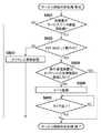
S601において、撮影装置101、印刷装置102は、自装置がサービスのデータ通信の開始側であるか否かを判定する。サービスのデータ通信の開始側である場合(S601;YES)、S602へ進む。一方、サービスのデータ通信の開始側ではない場合(S601;NO)、サービス開始判定処理を終了する。 In step S <b> 601, the photographing
S602において、撮影装置101、印刷装置102は、自装置がP2P GOとして動作中であるか否かを判定する。P2P GOとして動作している場合(S602;YES)、S604へ進む。一方、P2P GOとして動作していない場合、すなわちP2P Clientとして動作している場合(S602;NO)、S603へ進む。本実施形態では、撮影装置101はP2P GOとして動作しているおり、印刷サービスのデータ通信の開始側であるため、S604へ進む。一方、印刷装置102はP2P Clientとして動作しており、印刷サービスのデータ通信の開始待ち受け側であるため、S603へ進む。 In step S602, the
S603において、P2P Client側の通信装置(印刷装置102)は、IPアドレスの重複確認処理を実施する。IPアドレスの重複確認は、GARP(Gratuious ARP)(図4のM411)を用いて行なわれる。本実施形態では、GARPを規定の時間間隔で3回送信するものとする。3回送信した後応答がなければ、IPアドレスを重複して設定している通信装置は存在しないと判断し、S510で取得したIPアドレスをネットワークI/Fに設定する。なお、送信回数は3回に限るものではなく、回数は任意に設定すればよい。S603の処理の後、サービス開始判定処理を終了する。 In step S <b> 603, the communication device (printing device 102) on the P2P client side performs IP address duplication confirmation processing. The IP address duplication check is performed using GARP (Gratuous ARP) (M411 in FIG. 4). In the present embodiment, GARP is transmitted three times at regular time intervals. If there is no response after three transmissions, it is determined that there is no communication device in which duplicate IP addresses are set, and the IP address acquired in S510 is set in the network I / F. Note that the number of transmissions is not limited to three, and the number of transmissions may be set arbitrarily. After the process of S603, the service start determination process is terminated.
S604において、P2P GO側の通信装置(撮影装置101)は、相手通信装置(印刷装置102)がIPアドレスの重複確認を実施するか否かを判定する。相手通信装置がIPアドレスの重複確認処理を実施するか否かを示す情報をWi−Fi Directあるいは無線LAN規定の任意フレームの拡張情報として相手通信装置から取得し、当該情報に基づいて判定を行う。当該取得処理は、S604において実施されてもよいし、事前に実施されていてもよい。 In step S <b> 604, the communication device (photographing device 101) on the P2P GO side determines whether the partner communication device (printing device 102) performs IP address duplication confirmation. Information indicating whether or not the partner communication device performs IP address duplication confirmation processing is acquired from the partner communication device as Wi-Fi Direct or extended information of an arbitrary frame defined by the wireless LAN, and determination is performed based on the information. . The acquisition process may be performed in S604 or may be performed in advance.
相手通信装置がIPアドレスの重複確認を実施しないと判定された場合は(S604;YES)、サービス開始判定処理を終了する。一方、相手通信装置がIPアドレスの重複確認処理を実施すると判定された場合(S604;NO)、S605に進む。なお、相手通信装置がIPアドレスの重複確認処理を実施するか否かの情報を相手通信装置から取得していない場合には、S605へ進むようにしてもよい。ここで、相手通信装置側でIPアドレスの重複確認を実施するか否かを判定する処理の詳細については、図8を参照して後述する。本実施形態では、撮影装置101は、相手通信装置がIPアドレスの重複確認を実施するか否かの情報を取得していないものとし、S605へ進むものとする。なお、S604の判定処理を省略してもよい。その場合、S604の判定処理は実施されずにS605へ進む。 If it is determined that the partner communication device does not perform IP address duplication check (S604; YES), the service start determination process is terminated. On the other hand, when it is determined that the partner communication device performs the IP address duplication confirmation process (S604; NO), the process proceeds to S605. If the partner communication apparatus has not acquired information from the partner communication apparatus as to whether or not to perform the IP address duplication confirmation process, the process may proceed to S605. Here, details of the process for determining whether or not to perform duplication confirmation of the IP address on the partner communication device side will be described later with reference to FIG. In the present embodiment, it is assumed that the photographing
S605において、P2P GO側の通信装置(撮影装置101)は、サービスのデータ通信を開始するにあたり、タイマを起動する。タイマの起動は、P2P Client側の通信装置(印刷装置102)がIPアドレスの重複確認を実施する期間を考慮して、データ通信の開始を遅延させるために実施される。タイマ値は規定の値でもよいし、ランダムな値を用いてもよい。また、タイマ値をサービスの相手通信装置から予め取得するようにしてもよい。その場合、取得方法は、Service Discoveryにより取得してもよい。同様に、Wi−Fi Directあるいは無線LANに規定される各種フレームから任意のフレームの拡張情報としてタイマ値を取得するようにしてもよい。また、無線LANより上位レイヤで新規メッセージを拡張して通知するようにしてもよく、これらに限るものでもない。タイマの起動後、S606へ進む。 In step S <b> 605, the communication device (photographing device 101) on the P2P GO side activates a timer when starting service data communication. The timer is activated in order to delay the start of data communication in consideration of the period during which the communication device (printing device 102) on the P2P Client side performs duplication confirmation of the IP address. The timer value may be a specified value or a random value. The timer value may be acquired in advance from the service partner communication device. In this case, the acquisition method may be acquired by using Service Discovery. Similarly, a timer value may be acquired as extended information of an arbitrary frame from various frames defined in Wi-Fi Direct or wireless LAN. Further, a new message may be extended and notified at a higher layer than the wireless LAN, and the present invention is not limited thereto. After the timer is started, the process proceeds to S606.
S606において、P2P GO側の通信装置(撮影装置101)は、タイマが満了したか否かを判定する。タイマが満了した場合(S606;YES)、サービス開始判定処理を終了する。一方、タイマが満了していない場合(S606;NO)、満了するまで待機する。本実施形態では、撮影装置101においてタイマが起動し、サービスのデータ通信の開始が遅延される。このように、サービスの開始をタイマの満了に応じた時間遅延させる。図6のサービス開始判定処理が終了すると、図5のS512へ進む。 S512において、撮影装置101、印刷装置102は、サービス開始判定処理での判定結果に応じた処理を実施して、サービスのデータ通信を実施する。 In step S606, the P2P GO side communication apparatus (imaging apparatus 101) determines whether the timer has expired. If the timer has expired (S606; YES), the service start determination process is terminated. On the other hand, if the timer has not expired (S606; NO), the process waits until it expires. In the present embodiment, a timer is started in the photographing
サービスのデータ通信の開始側がサービスのためのデータを送信することにより、サービスのデータ通信が開始される。サービスのデータ通信の開始待受け側は、データ通信の開始を受けて、データの応答処理を行うことになる。 The data communication of the service is started when the service data communication start side transmits the data for the service. The service data communication start standby side performs data response processing in response to the start of data communication.
本実施形態では、撮影装置101が印刷サービスのデータ通信の開始側であるため、印刷サービスのデータ(M412)を送信する。そして、印刷装置102が印刷サービスの応答データ(M413)を送信する。以上で図4及び図5の各処理が終了する。 In this embodiment, since the photographing
以上説明したように、本実施形態では、無線ネットワークでの自装置の役割情報と、自装置がサービスのデータ通信の開始側であるか否かを示す情報とに基づいて、相手通信装置とのサービスのデータ通信の開始時期を自律的に制御する。これにより、相手通信装置との間でサービスのためのデータ通信の開始時期に不整合が生じることを防止し、データの再送や送信タイムアウトの発生を抑止することができる。 As described above, in the present embodiment, based on the role information of the own device in the wireless network and the information indicating whether or not the own device is the data communication start side of the service, It autonomously controls the start time of service data communication. As a result, it is possible to prevent inconsistency in the start timing of data communication for service with the counterpart communication device, and to suppress the occurrence of data retransmission and transmission timeout.
[サービス開始判定処理の変形例1]
サービス開始判定処理の一例として、図6のフローチャートを用いて説明したが、本実施形態に係るサービス開始判定処理の変形例1について、図7を参照して説明する。[Modification 1 of service start determination process]
Although an example of the service start determination process has been described with reference to the flowchart of FIG. 6, Modification 1 of the service start determination process according to the present embodiment will be described with reference to FIG. 7.
図7は、変形例1に係る撮影装置101、印刷装置102が実施するサービス開始判定処理の手順を示すフローチャートである。 FIG. 7 is a flowchart illustrating a procedure of service start determination processing performed by the
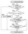
S701−S704の各処理は、S601−S604の各処理と同等であるため、説明を省略する。なお、S704の処理はS604の処理と同様に、実施しないようにしてもよい。 Since each process of S701-S704 is equivalent to each process of S601-S604, description is abbreviate | omitted. Note that the processing in S704 may not be performed in the same manner as the processing in S604.
S705において、P2P GO側の通信装置(撮影装置101)は、相手通信装置(印刷装置102)との間でIP通信が可能になったか否かを判定する。IP通信が可能になったと判定された場合(S705;YES)、サービス開始判定処理を終了する。 In step S <b> 705, the communication device (imaging device 101) on the P2P GO side determines whether IP communication with the partner communication device (printing device 102) has become possible. If it is determined that IP communication is possible (S705; YES), the service start determination process is terminated.
IP通信が可能になったか否かは、例えば、DHCPサーバ機能で相手通信装置に割り振ったIPアドレスに対して、IP通信が可能になったかを確認する。ICMP(Internet Control Message Protocol)のecho requestを送信し、echo replyを受けることでIP通信が可能になったことを確認できる。あるいは、相手通信装置からIP通信が可能になった旨のメッセージを受信するようにしてもよい。 Whether or not IP communication has become possible is confirmed, for example, by checking whether or not IP communication has become possible with respect to the IP address assigned to the partner communication device by the DHCP server function. An ICMP (Internet Control Message Protocol) echo request is transmitted, and it can be confirmed that IP communication is enabled by receiving echo reply. Or you may make it receive the message to the effect that IP communication was attained from the other party communication apparatus.
これにより、図6のフローチャートで用いたタイマ値よりも確実にIP通信が可能になったことを検知してからデータ通信を実施することができる。 Thereby, data communication can be carried out after detecting that IP communication can be performed more reliably than the timer value used in the flowchart of FIG.
[サービス開始判定処理の変形例2]
同様に、本実施形態に係るサービス開始判定処理の変形例2について、図8を参照して説明する。図8は、変形例2に係る本実施形態における撮影装置101、印刷装置102が実施するサービス開始判定処理の手順を示すフローチャートである。[Modification 2 of service start determination processing]
Similarly, a second modification of the service start determination process according to the present embodiment will be described with reference to FIG. FIG. 8 is a flowchart illustrating a procedure of a service start determination process performed by the
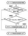
S801において、撮影装置101、印刷装置102は、自装置がサービスのデータ通信の開始待受け側であるか否かを判定する。サービスのデータ通信の開始待受け側である場合(S801;YES)、S802へ進む。一方、サービスのデータ通信の開始待受け側ではない場合、すなわちデータ通信の開始側である場合(S601;NO)、サービス開始判定処理を終了する。本実施形態では、印刷装置102の場合、印刷サービスのデータ通信の開始待受け側であるため、S802へ進む。一方、撮影装置101の場合、印刷サービスのデータ通信の開始側であるため、処理を終了する。 In step S <b> 801, the
S802において、撮影装置101、印刷装置102は、自装置がP2P Clientとして動作中であるか否かを判定する。P2P Clientとして動作している場合(S802;YES)、S803へ進む。一方、P2P Clientとして動作していない場合、すなわちP2P GOとして動作している場合(S802;NO)、サービス開始判定処理を終了する。本実施形態では印刷装置102がP2P Clientとして動作しているため、S803へ進む。 In step S802, the
S803において、P2P Client側の通信装置(印刷装置102)は、IPアドレスの重複確認を実施しないと判定する。Wi−Fi Directにおいては、DHCP機能によるIPアドレス取得が規格内で規定されている。同一IPアドレスネットワーク(同一サブネット)は、無線LANネットワーク内で限定され、無線LANネットワーク内の端末のIPアドレスはP2P GOのDHCPサーバ機能によって管理されている。 In step S803, the communication device (printing device 102) on the P2P client side determines that the IP address duplication check is not performed. In Wi-Fi Direct, IP address acquisition by the DHCP function is defined in the standard. The same IP address network (same subnet) is limited in the wireless LAN network, and the IP address of the terminal in the wireless LAN network is managed by the DHCP server function of P2P GO.
そのため、IPアドレスの重複が発生する可能性は低いため、P2Pグループのようにピアツーピアネットワークを構成した場合に限り、IPアドレスの重複確認を実施しないと判定する。その場合、IPアドレスの重複確認を実施するか否かをWi−Fi Directあるいは無線LAN規定の任意フレームの拡張情報として相手通信装置へ通知する。なお、当該通知は、S803の処理で実施してもよいし、事前に相手通信装置へ通知するようにしてもよい。なお、IPアドレスの重複確認を実施するか否かの通知は実施しないようにしてもよい。 Therefore, since there is a low possibility that IP address duplication will occur, it is determined that IP address duplication confirmation is not performed only when a peer-to-peer network is configured as in a P2P group. In this case, whether or not to perform duplication confirmation of the IP address is notified to the other communication device as Wi-Fi Direct or extended information of an arbitrary frame defined by the wireless LAN. The notification may be performed in the process of S803 or may be notified to the partner communication apparatus in advance. Note that notification of whether or not to perform duplication confirmation of IP addresses may not be performed.
これにより、IPアドレスの重複確認を実施しないため、サービスのデータ通信の開始までの時間を短縮することができる。 As a result, since duplication confirmation of the IP address is not performed, the time until the start of service data communication can be shortened.
また、P2P GO、P2P Client側の機器をサービスの開始側か否かの情報に基づいて決定するようにしてもよい。サービスの開始側が常にP2P Client側の機器になることで、IPアドレスの重複確認後、ネットワークI/FにIPアドレスを設定してからサービスを開始することになる。これにより、サービスの開始時期の不整合を無線ネットワークの役割決定により、防止することができる。 Further, the device on the P2P GO and P2P Client side may be determined based on information on whether or not the device is the service start side. Since the service start side is always a device on the P2P Client side, after confirming the IP address duplication, the service is started after the IP address is set in the network I / F. Thereby, inconsistency of the service start time can be prevented by determining the role of the wireless network.
(第2実施形態)
第1実施形態では、撮影装置101と印刷装置102との間で新規に無線ネットワーク103を形成する場合について説明した。本実施形態では、図9に示すように、撮影装置901、撮影装置902間で既に無線ネットワーク904が構築されており、印刷装置903が無線ネットワーク904に接続する場合の処理について説明する。なお、撮影装置902がP2P GOとして無線ネットワーク904を構築しており、撮影装置901がP2P Clientとして無線ネットワーク904に接続しているものとする。(Second Embodiment)
In the first embodiment, the case where the
本実施形態における撮影装置901、撮影装置902、および、印刷装置903の機能ブロック図は、それぞれ図2の撮影装置101、および図3の印刷装置102と同等であるため、ここでの説明は省略する。 The functional block diagrams of the
以下、本実施形態に係る処理内容について、図5、図8、および図10を参照して説明する。図10は、第2実施形態に係る撮影装置901、撮影装置902および印刷装置903の間でそれぞれサービスを実施するまでの処理を示す装置間のシーケンス図である。 Hereinafter, processing contents according to the present embodiment will be described with reference to FIGS. 5, 8, and 10. FIG. 10 is an inter-device sequence diagram illustrating processing until services are performed among the
はじめに、撮影装置902と印刷装置903との間で、ユーザにより印刷サービスの開始指示があるものとする。 First, it is assumed that a user issues a print service start instruction between the photographing
撮影装置902および印刷装置903は、共にS501において、サービスの開始要求を受けると、S502に進む。 When both the
撮影装置902は、S502において、第1実施形態と同様に通信相手の探索処理(M1001、M1002)を実施する。本実施形態では、撮影装置902はP2P GOとして起動しているため、探索待受け側として相手装置からの探索を待ちうける。印刷装置903は、探索実施側として探索を実施する。印刷装置903は、S502においてSCAN処理、Service Discovery処理等を実施し、撮影装置902を発見する。SCAN処理により撮影装置902がP2P GOとして動作中であることを認識できる。印刷装置903は、P2P Cilentとして、無線ネットワーク904に接続するために端末局モードを起動する。 In step S502, the
なお、撮影装置902はP2P GOとして動作中ではあるが、撮影装置902がサービスの開始側であることから、撮影装置902が探索実施側として探索処理を実施するようにしてもよい。その場合、撮影装置901とのデータ通信が実施されていない間に探索を実施するようにしてもよい。以降、撮影装置902および印刷装置903間の処理フローは、S504の処理まで第1実施形態と同様であるため、ここでの説明は省略する。 Although the
S504において、撮影装置902は既にP2P GOとして起動しているため、撮影装置902と印刷装置903との間でのWi−Fi Direct接続処理において、Group Negotiationはスキップされる。撮影装置902は、P2Pグループを維持した状態で、新規通信装置(印刷装置903)からのWi−Fi Direct接続を待受ける。 In S504, since the
撮影装置902と印刷装置903との間でWi−Fi Directの接続処理(M1003)が完了すると、撮影装置902はP2P GOであるため(S505;YES)、S506へ進む。ただし、本実施形態では、撮影装置902は既にDHCPサーバを起動済みであるため、S506の処理はスキップされ、S507へ進むことになる。一方、印刷装置903はP2Pクライアントとして起動しているため(S505;NO)、S509へ進み、S510においてIPアドレスの取得処理を実施する(M1004−M1007)。ここで、M1004−M1007はそれぞれ図4のM407−M410と同様の処理である。 When the Wi-Fi Direct connection process (M1003) is completed between the
撮影装置902が実施するS507以降の処理は、第1実施形態と同様であるため、ここでの説明は省略する。同様に、印刷装置903が実施するS510以降の処理は、第1実施形態と同様であるため、ここでの説明は省略する。 Since the processing after S507 performed by the photographing
そして、サービス開始判定処理に基づいて、撮影装置902と印刷装置903との間で印刷サービスのデータ通信が開始されることになる(M1008−M1012)。ここで、M1008−M1012はそれぞれ図4のM411−M413と同様の処理である。 Then, based on the service start determination process, print service data communication is started between the photographing
なお、サービス開始判定処理の一例として、図8のフローチャートにおいて、第1実施形態ではS803においてIPアドレスの重複確認を実施しないと判定した。 As an example of the service start determination process, in the flowchart of FIG. 8, in the first embodiment, it is determined in S803 that the IP address duplication check is not performed.
しかし、本実施形態のように、既に形成されているP2Pグループに通信装置が参入するような場合、既存のP2Pグループ内のP2P Client端末において、手動でIPアドレスの変更が実施されている場合も考えられる。本実施形態では、例えば撮影装置901がIPアドレスを変更していた場合が該当する。IPアドレスが手動で変更されていた場合、撮影装置901と印刷装置903との間でIPアドレスが重複する可能性がある。 However, as in this embodiment, when a communication device enters a P2P group that has already been formed, the IP address may be manually changed at the P2P Client terminal in the existing P2P group. Conceivable. In the present embodiment, for example, the case where the photographing
そのため、S803の判定処理において、さらに相手通信装置と自装置との間で新規に無線LANネットワーク(P2Pグループ)を形成する場合のみ、IPアドレスの重複確認を実施しないとしてもよい。すなわち、無線LANネットワーク内で1対1接続が確実な場合のみ、IPアドレスの重複確認を実施しないものとする。より具体的には、自装置がクライアント側として動作していることを役割情報が示しており、自装置がデータ通信の開始を待ち受ける側であり、且つ相手通信装置との間で無線ネットワークを新規に形成する場合に、クライアント側の動作により取得したIPアドレスに対して無線ネットワークにおける重複確認を実施しないと判定するものである。 For this reason, in the determination process of S803, the IP address duplication check may not be performed only when a wireless LAN network (P2P group) is newly formed between the partner communication apparatus and the own apparatus. That is, the IP address duplication check is not performed only when a one-to-one connection is ensured in the wireless LAN network. More specifically, the role information indicates that the own device is operating as the client side, the own device is a side waiting for the start of data communication, and a new wireless network is established with the partner communication device. In this case, it is determined that duplication confirmation in the wireless network is not performed for the IP address acquired by the operation on the client side.
新規に無線LANネットワークを形成するか否かは、SCAN処理時の結果から、相手通信装置が既にP2P GOとして動作中であるか否かによって判定することができる。本実施形態では、印刷装置903において、SCAN処理時に撮影装置902が既にP2P GOとして動作していると判定できるため、S803ではIPアドレスの重複確認を実施すると判定することになる。 Whether or not to newly form a wireless LAN network can be determined from whether or not the partner communication device is already operating as a P2P GO from the result of the SCAN process. In this embodiment, since it can be determined in the
なお、本実施形態では、サービスのデータ通信の開始側(撮影装置902)がP2P GOとして既に無線ネットワーク904を形成している場合について説明したが、これに限るものではない。サービスのデータ通信の開始待受け側(印刷装置903)がP2P GOとして動作し無線LANネットワークを形成していてもよい。例えば、撮影装置901と印刷装置903との間で無線ネットワーク904を構築しており、撮影装置902が無線ネットワーク904に接続するような場合である。このような場合でも本実施形態を適用することができる。 In the present embodiment, the case where the start side of the data communication of the service (the imaging device 902) has already formed the
なお、本実施形態では、撮影装置902がP2P GOとして動作し無線ネットワーク904を形成している場合について記載したが、これに限るものではない。撮影装置901がP2P GOとして動作し無線ネットワーク904を形成しており、撮影装置902がP2P Clientとして動作していてもよい。 In the present embodiment, the case where the photographing
撮影装置902が、無線ネットワーク904に接続しつつ、印刷装置903との間で新規に無線LANネットワーク(P2Pグループ)を形成するようにしてもよい。その場合、撮影装置902において、1つの無線LAN I/F上で、2つの無線LANネットワークを切り替えて通信する、あるいは、複数の無線LAN I/Fを所持して各I/Fで無線LAN通信を行なうことにより実現できる。無線ネットワーク904とは別の無線LANネットワークが形成される場合は、新規無線LANネットワーク(P2Pグループ)を構成するものとして、第1実施形態が適用される。 The
以上説明したように、本実施形態によれば、既にP2Pグループが形成されている場合でも、相手通信装置とのサービスのデータ通信の開始時期を自律的に制御し、サービスの開始時期に不整合が生じることを防止することができる。 As described above, according to the present embodiment, even when a P2P group is already formed, the start time of data communication of the service with the counterpart communication device is controlled autonomously, and the start time of the service is inconsistent. Can be prevented.
なお、各実施形態において、撮影装置および印刷装置の無線通信にIEEE802.11準拠の無線LANを適用した場合について説明したが、これに限る物ではない。例えば、ワイヤレスUSB、MBOA、Bluetooth(登録商標)、UWB、ZigBee、(Near Field Communication)等の無線通信媒体を用いて実施してもよい。ここで、MBOAは、Multi Band OFDM Allianceの略である。また、UWBには、ワイヤレスUSB、ワイヤレス1394、WINETなどが含まれる。 In each embodiment, the case where the wireless LAN conforming to IEEE 802.11 is applied to the wireless communication between the photographing apparatus and the printing apparatus has been described. However, the present invention is not limited to this. For example, you may implement using wireless communication media, such as wireless USB, MBOA, Bluetooth (trademark), UWB, ZigBee, and (Near Field Communication). Here, MBOA is an abbreviation for Multi Band OFDM Alliance. UWB includes wireless USB, wireless 1394, WINET, and the like.
また、各実施形態において、無線LANの通信形態としてインフラストラクチャ・モードの場合について説明したが、アドホック・モードの場合においても実施してもよい。 In each embodiment, the case of the infrastructure mode has been described as the communication mode of the wireless LAN. However, the embodiment may also be implemented in the case of the ad hoc mode.
各実施形態において、無線LANの接続処理にWi−Fi Directを用いる場合について説明したが、無線LANの接続処理はこれに限るものではない。別のプロトコル処理を用いて実現してもよいし、通常の無線LAN接続する場合でも本発明を適用することができる。 In each embodiment, the case where Wi-Fi Direct is used for wireless LAN connection processing has been described, but wireless LAN connection processing is not limited to this. The present invention can be applied even when a normal wireless LAN connection is established, using another protocol process.
各実施形態において、P2Pグループを形成する際に、IPアドレスの割当てにDHCPを用いる場合について説明したが、IPアドレスを別の機能を用いて割当てるようにしてもよい。例えば無線LANとは別の媒体を用いてIPアドレスを相手通信装置に割当てる場合などである。その場合、本実施形態のDHCPに関連する処理はスキップされ、P2Pグループ形成後にサービス開始判定処理が実施される。 In each embodiment, the case where DHCP is used for IP address assignment when forming a P2P group has been described. However, an IP address may be assigned using another function. For example, there is a case where an IP address is assigned to the partner communication device using a medium different from the wireless LAN. In that case, the processing related to DHCP of this embodiment is skipped, and the service start determination processing is performed after the P2P group is formed.
また、IPアドレスの割当ては主にIPv4アドレスの場合に実施されるが、
機器固有のIPアドレスを用いる場合は、DHCP処理はスキップされることになる。例えばIPv6アドレスを用いる場合などである。相手通信装置からIPアドレスの体系情報(IPv4アドレスおよびIPv6アドレスの対応情報など)を取得し、機器固有のIPアドレスを利用してP2Pグループを形成する否かを、P2Pグループ形成前に予め判定するようにしてもよい。取得方法はWi−Fi Directあるいは無線LAN規定の任意フレームの拡張情報としてIPアドレスの体系情報を取得する。その場合、IPアドレスの重複判定処理はスキップされ、P2Pグループ形成後にサービス開始判定処理が実施されることになる。In addition, IP address assignment is mainly performed for IPv4 addresses,
When a device-specific IP address is used, the DHCP process is skipped. For example, when using an IPv6 address. IP address system information (IPv4 address and IPv6 address correspondence information, etc.) is acquired from the partner communication device, and it is determined in advance before forming a P2P group whether or not a P2P group is formed using a device-specific IP address. You may do it. The acquisition method acquires system information of an IP address as extended information of an arbitrary frame defined by Wi-Fi Direct or wireless LAN. In this case, the IP address duplication determination process is skipped, and the service start determination process is performed after the P2P group is formed.
各実施形態において、IPアドレスの重複確認にGARPを用いる場合について説明したが、IPアドレスの重複確認方法はこれに限るものではない。他のプロトコルを用いて重複確認をするようにしてもよく、その場合においても、IPアドレスの重複確認の処理を置き換えることで、本実施形態を適用することができる。 In each embodiment, the case where GARP is used for IP address duplication confirmation has been described, but the IP address duplication confirmation method is not limited to this. The duplication confirmation may be performed using another protocol, and even in this case, the present embodiment can be applied by replacing the IP address duplication confirmation process.
各実施形態において、サービスのデータ通信を開始するための開始判定処理を実施したが、サービスのデータ通信に限るものではない。例えば、サービスを開始するために必要な事前のネゴシエーション処理や探索処理などIPレイヤ上で実施される全ての通信に適応することができる。 In each embodiment, the start determination process for starting service data communication is performed. However, the present invention is not limited to service data communication. For example, the present invention can be applied to all communications performed on the IP layer such as prior negotiation processing and search processing necessary for starting a service.
(その他の実施形態)
また、本発明は、以下の処理を実行することによっても実現される。即ち、上述した実施形態の機能を実現するソフトウェア(プログラム)を、ネットワーク又は各種記憶媒体を介してシステム或いは装置に供給し、そのシステム或いは装置のコンピュータ(またはCPUやMPU等)がプログラムを読み出して実行する処理である。(Other embodiments)
The present invention can also be realized by executing the following processing. That is, software (program) that realizes the functions of the above-described embodiments is supplied to a system or apparatus via a network or various storage media, and a computer (or CPU, MPU, or the like) of the system or apparatus reads the program. It is a process to be executed.
Claims (13)
Translated fromJapanese無線ネットワークを介して他の通信装置と通信する際に、前記通信装置が、前記他の通信装置にアドレスを割り当てる第1の装置として動作するか、前記他の通信装置からアドレスを割り当てられる第2の装置として動作するかを判定する第1の判定手段と、
前記第1の判定手段により前記第1の装置として動作すると判定された場合であって、前記他の通信装置が割り当てられたアドレスの重複確認を行う場合、当該重複確認に対応する所定時間が少なくとも経過した後に、データの送信を開始するように制御する制御手段と、
を有することを特徴とする通信装置。A communication device,
When communicating with another communication device via a wireless network, the communication device operates as a first device that assigns an address to the other communication device, or is assigned a second address from the other communication device. First determination means for determining whether or not to operate as a device;
In the case whereit is determined by the first determination means to operate as the first device, and when theother communication device performs duplication confirmation of the assigned address,at least a predetermined time corresponding to the duplication confirmation is at least after a lapse of, and control means for controlling the so thattostart transmissionof data,
A communication apparatus comprising:
前記制御手段は、前記第1の判定手段により前記第1の装置として動作すると判定され、かつ、前記第2の判定手段により前記通信装置がデータ通信の開始側であると判定された場合であって、前記他の通信装置が割り当てられたアドレスの重複確認を行う場合、当該重複確認に対応する所定時間が少なくとも経過した後に、データの送信を開始するように制御することを特徴とする請求項1に記載の通信装置。A second determination means for determining whether or not the communication device is a start side of data communication with the other communication device;
The control means is a case where it is determined by the first determination means to operate as the first device, and the second determination means determines that the communication device is a data communication start side. Te,when performing duplication check of addresses which the other communication device is allocated,after a predetermined time corresponding to the duplication check has at least passed, claims and controlling the so thattostartsending data Item 4. The communication device according to Item 1.
前記制御手段は、前記第1の判定手段により前記第1の装置として動作すると判定された場合、前記第1の確認手段により前記他の通信装置とIPレイヤ上で規定の通信が可能となったことが確認されたことに応じて、データ送信を開始するように制御することを特徴とする請求項1または2に記載の通信装置。A first confirmation means for confirming that prescribed communication with the other communication device on the IP layer is possible;
When it is determined by the first determination unit that the control unit operates as the first device, the first confirmation unit enables predetermined communication with the other communication device on the IP layer. 3. The communication apparatus according to claim 1, wherein control is performed so that data transmission is started in response to the confirmation.
前記制御手段は、前記第1の判定手段により前記第1の装置として動作すると判定された場合、前記取得手段により取得された前記タイミング情報に基づいて、データ送信を開始するように制御することを特徴とする請求項1または2に記載の通信装置。Further comprising an acquisition means for acquiring timing information related to data reception start timing in the other communication device from the other communication device;
The control means performs control so as to start data transmission based on the timing information acquired by the acquisition means when the first determination means determines that the first apparatus operates as the first device. The communication apparatus according to claim 1 or 2, characterized in that:
無線ネットワークを介して他の通信装置と通信する際に、前記通信装置が、前記他の通信装置にアドレスを割り当てる第1の装置として動作するか、前記他の通信装置からアドレスを割り当てられる第2の装置として動作するかを判定する第1の判定工程と、
前記第1の判定工程により前記第1の装置として動作すると判定された場合であって、前記他の通信装置が割り当てられたアドレスの重複確認を行う場合、当該重複確認に対応する所定時間が少なくとも経過した後に、データの送信を開始するように制御する制御工程と、
を有することを特徴とする通信装置の制御方法。A communication device control method comprising:
When communicating with another communication device via a wireless network, the communication device operates as a first device that assigns an address to the other communication device, or is assigned a second address from the other communication device. A first determination step of determining whether to operate as a device of
In the case whereit is determined in the first determination step that the device operates as the first device, and theother communication device performs duplication confirmation of the assigned address,at least a predetermined time corresponding to the duplication confirmation is at least after a lapse of a control step for controllingtostartsending data,
A method for controlling a communication apparatus, comprising:
Priority Applications (2)
| Application Number | Priority Date | Filing Date | Title |
|---|---|---|---|
| JP2013238268AJP6204800B2 (en) | 2013-11-18 | 2013-11-18 | COMMUNICATION DEVICE, COMMUNICATION DEVICE CONTROL METHOD, AND PROGRAM |
| US14/526,594US10015045B2 (en) | 2013-11-18 | 2014-10-29 | Communication apparatus that delays a start of data communication based on information obtained from another communication apparatus, method for controlling the same, and non-transitory computer readable storage medium |
Applications Claiming Priority (1)
| Application Number | Priority Date | Filing Date | Title |
|---|---|---|---|
| JP2013238268AJP6204800B2 (en) | 2013-11-18 | 2013-11-18 | COMMUNICATION DEVICE, COMMUNICATION DEVICE CONTROL METHOD, AND PROGRAM |
Publications (3)
| Publication Number | Publication Date |
|---|---|
| JP2015099990A JP2015099990A (en) | 2015-05-28 |
| JP2015099990A5 JP2015099990A5 (en) | 2016-09-08 |
| JP6204800B2true JP6204800B2 (en) | 2017-09-27 |
Family
ID=53173222
Family Applications (1)
| Application Number | Title | Priority Date | Filing Date |
|---|---|---|---|
| JP2013238268AActiveJP6204800B2 (en) | 2013-11-18 | 2013-11-18 | COMMUNICATION DEVICE, COMMUNICATION DEVICE CONTROL METHOD, AND PROGRAM |
Country Status (2)
| Country | Link |
|---|---|
| US (1) | US10015045B2 (en) |
| JP (1) | JP6204800B2 (en) |
Family Cites Families (23)
| Publication number | Priority date | Publication date | Assignee | Title |
|---|---|---|---|---|
| US4773080A (en) | 1984-04-25 | 1988-09-20 | Canon Kabushiki Kaisha | Data communication equipment |
| JP2548555B2 (en) | 1987-02-16 | 1996-10-30 | キヤノン株式会社 | Fax machine |
| US5073827A (en) | 1987-09-22 | 1991-12-17 | Canon Kabushiki Kaisha | Image communication apparatus |
| JP2735367B2 (en) | 1990-08-13 | 1998-04-02 | キヤノン株式会社 | Image communication device |
| US5684604A (en) | 1992-04-28 | 1997-11-04 | Canon Kabushiki Kaisha | Image transmission method and apparatus therefor |
| US5739920A (en) | 1992-06-08 | 1998-04-14 | Canon Kabushiki Kaisha | Image processing apparatus |
| EP0574910B1 (en) | 1992-06-18 | 2002-01-02 | Canon Kabushiki Kaisha | Image transmitting apparatus |
| US5392133A (en) | 1992-06-30 | 1995-02-21 | Canon Kabushiki Kaisha | Apparatus and method for transmitting image data in a format adapted to a condition of a destination |
| JP2003008585A (en)* | 2001-04-20 | 2003-01-10 | Toshiba Corp | Communication control device, communication control method, communication device, and communication method |
| US20030088650A1 (en)* | 2001-07-30 | 2003-05-08 | Lockheed Martin Corporation | Using a diskless client network topology for disk duplication and configuration |
| JP2003152731A (en)* | 2001-11-16 | 2003-05-23 | Mitsumi Electric Co Ltd | Communication device, ip address acquisition method, and roaming method |
| JP5267536B2 (en)* | 2003-10-24 | 2013-08-21 | ソニー株式会社 | Wireless communication system, wireless communication apparatus, wireless communication method, and computer program |
| WO2006129680A1 (en)* | 2005-05-30 | 2006-12-07 | Matsushita Electric Industrial Co., Ltd. | Communication device provided with arp function |
| JP2007058743A (en)* | 2005-08-26 | 2007-03-08 | Canon Inc | Network device and power saving control method for network device |
| KR101410619B1 (en)* | 2007-09-28 | 2014-06-23 | 삼성전자주식회사 | Zigbee network system and method for assigning ip address of client device in zigbee network system |
| CN102027767B (en)* | 2008-05-16 | 2015-05-13 | 日本电气株式会社 | Communication device, communication method and communication control program |
| US8250207B2 (en)* | 2009-01-28 | 2012-08-21 | Headwater Partners I, Llc | Network based ambient services |
| JP4789994B2 (en)* | 2008-11-11 | 2011-10-12 | パナソニック株式会社 | Wireless communication method, wireless communication terminal accommodating apparatus, wireless communication terminal, communication control method, and communication method |
| JP5821390B2 (en)* | 2011-08-10 | 2015-11-24 | 株式会社リコー | Wireless communication apparatus, wireless communication program, and wireless communication method |
| JP5250689B2 (en)* | 2011-12-05 | 2013-07-31 | シャープ株式会社 | Base station and terminal for wireless LAN system |
| US20130198408A1 (en)* | 2012-01-26 | 2013-08-01 | Schneider Electric Industries Sas | IP Parameter Determination and Configuration |
| US20130343350A1 (en)* | 2012-06-20 | 2013-12-26 | Uri Weinrib | Synchronization in a communication system |
| CN103856497B (en)* | 2012-11-29 | 2017-06-06 | 华为终端有限公司 | Terminal management method, equipment and home network in home network |
- 2013
- 2013-11-18JPJP2013238268Apatent/JP6204800B2/enactiveActive
- 2014
- 2014-10-29USUS14/526,594patent/US10015045B2/enactiveActive
Also Published As
| Publication number | Publication date |
|---|---|
| JP2015099990A (en) | 2015-05-28 |
| US20150139029A1 (en) | 2015-05-21 |
| US10015045B2 (en) | 2018-07-03 |
Similar Documents
| Publication | Publication Date | Title |
|---|---|---|
| CN102572010B (en) | By the network that short haul connection is set up | |
| AU2013356802B2 (en) | Method and device for session initialization in wireless communication system | |
| US9699819B2 (en) | Method and apparatus for establishing session in wireless communication system | |
| US9986591B2 (en) | Function execution apparatus | |
| EP2745618B1 (en) | Apparatus and method for determining group owner in establishment of wi-fi direct connection | |
| US9699715B2 (en) | Discovery method and device in a wireless communication system | |
| US8892722B1 (en) | Peer-to-peer discovery systems and methods | |
| US9807677B2 (en) | Service discovery method and device in wireless LAN system | |
| US10594559B2 (en) | Communication apparatus | |
| US8954502B1 (en) | Infrastructure devices in peer-to-peer environments | |
| EP2884813A1 (en) | Method and apparatus for generating p2p group for wi-fi direct service | |
| JP6271843B2 (en) | COMMUNICATION DEVICE, ITS CONTROL METHOD, PROGRAM | |
| US10051673B2 (en) | Method and apparatus for session initiation in wireless communication system | |
| JP6271839B2 (en) | COMMUNICATION DEVICE, COMMUNICATION DEVICE CONTROL METHOD, PROGRAM | |
| JP6204800B2 (en) | COMMUNICATION DEVICE, COMMUNICATION DEVICE CONTROL METHOD, AND PROGRAM | |
| US9554254B2 (en) | Communication apparatus, control method of communication apparatus, and program | |
| JP2014160319A (en) | Communication apparatus, method for controlling communication apparatus, and program | |
| JP6271838B2 (en) | COMMUNICATION DEVICE, COMMUNICATION DEVICE CONTROL METHOD, PROGRAM | |
| KR20130095983A (en) | Method and apparatus for providing of wifi direct based service | |
| JP2018518887A (en) | IP address allocation method and user equipment in D2D communication | |
| JP2020088712A (en) | Communication device and control method thereof | |
| RU2607248C1 (en) | Communication device, its control method and program | |
| JP2015097383A (en) | COMMUNICATION DEVICE, COMMUNICATION DEVICE CONTROL METHOD, AND PROGRAM | |
| JP6577718B2 (en) | COMMUNICATION DEVICE, COMMUNICATION DEVICE CONTROL METHOD, AND PROGRAM | |
| JP2014183390A (en) | Communication apparatus, control method of the same, and program |
Legal Events
| Date | Code | Title | Description |
|---|---|---|---|
| A521 | Request for written amendment filed | Free format text:JAPANESE INTERMEDIATE CODE: A523 Effective date:20160720 | |
| A621 | Written request for application examination | Free format text:JAPANESE INTERMEDIATE CODE: A621 Effective date:20160720 | |
| A977 | Report on retrieval | Free format text:JAPANESE INTERMEDIATE CODE: A971007 Effective date:20170515 | |
| A131 | Notification of reasons for refusal | Free format text:JAPANESE INTERMEDIATE CODE: A131 Effective date:20170529 | |
| A521 | Request for written amendment filed | Free format text:JAPANESE INTERMEDIATE CODE: A523 Effective date:20170721 | |
| TRDD | Decision of grant or rejection written | ||
| A01 | Written decision to grant a patent or to grant a registration (utility model) | Free format text:JAPANESE INTERMEDIATE CODE: A01 Effective date:20170804 | |
| A61 | First payment of annual fees (during grant procedure) | Free format text:JAPANESE INTERMEDIATE CODE: A61 Effective date:20170901 | |
| R151 | Written notification of patent or utility model registration | Ref document number:6204800 Country of ref document:JP Free format text:JAPANESE INTERMEDIATE CODE: R151 |