JP6202082B2 - Setting value change device - Google Patents
Setting value change deviceDownload PDFInfo
- Publication number
- JP6202082B2 JP6202082B2JP2015249748AJP2015249748AJP6202082B2JP 6202082 B2JP6202082 B2JP 6202082B2JP 2015249748 AJP2015249748 AJP 2015249748AJP 2015249748 AJP2015249748 AJP 2015249748AJP 6202082 B2JP6202082 B2JP 6202082B2
- Authority
- JP
- Japan
- Prior art keywords
- drag
- display
- button
- movement path
- hot water
- Prior art date
- Legal status (The legal status is an assumption and is not a legal conclusion. Google has not performed a legal analysis and makes no representation as to the accuracy of the status listed.)
- Active
Links
Images


Classifications
- G—PHYSICS
- G06—COMPUTING OR CALCULATING; COUNTING
- G06F—ELECTRIC DIGITAL DATA PROCESSING
- G06F3/00—Input arrangements for transferring data to be processed into a form capable of being handled by the computer; Output arrangements for transferring data from processing unit to output unit, e.g. interface arrangements
- G06F3/01—Input arrangements or combined input and output arrangements for interaction between user and computer
- G06F3/048—Interaction techniques based on graphical user interfaces [GUI]
- G06F3/0484—Interaction techniques based on graphical user interfaces [GUI] for the control of specific functions or operations, e.g. selecting or manipulating an object, an image or a displayed text element, setting a parameter value or selecting a range
- G06F3/0486—Drag-and-drop
- F—MECHANICAL ENGINEERING; LIGHTING; HEATING; WEAPONS; BLASTING
- F24—HEATING; RANGES; VENTILATING
- F24D—DOMESTIC- OR SPACE-HEATING SYSTEMS, e.g. CENTRAL HEATING SYSTEMS; DOMESTIC HOT-WATER SUPPLY SYSTEMS; ELEMENTS OR COMPONENTS THEREFOR
- F24D5/00—Hot-air central heating systems; Exhaust gas central heating systems
- F24D5/12—Hot-air central heating systems; Exhaust gas central heating systems using heat pumps
- F—MECHANICAL ENGINEERING; LIGHTING; HEATING; WEAPONS; BLASTING
- F24—HEATING; RANGES; VENTILATING
- F24F—AIR-CONDITIONING; AIR-HUMIDIFICATION; VENTILATION; USE OF AIR CURRENTS FOR SCREENING
- F24F11/00—Control or safety arrangements
- F—MECHANICAL ENGINEERING; LIGHTING; HEATING; WEAPONS; BLASTING
- F24—HEATING; RANGES; VENTILATING
- F24F—AIR-CONDITIONING; AIR-HUMIDIFICATION; VENTILATION; USE OF AIR CURRENTS FOR SCREENING
- F24F11/00—Control or safety arrangements
- F24F11/89—Arrangement or mounting of control or safety devices
- F—MECHANICAL ENGINEERING; LIGHTING; HEATING; WEAPONS; BLASTING
- F24—HEATING; RANGES; VENTILATING
- F24H—FLUID HEATERS, e.g. WATER OR AIR HEATERS, HAVING HEAT-GENERATING MEANS, e.g. HEAT PUMPS, IN GENERAL
- F24H1/00—Water heaters, e.g. boilers, continuous-flow heaters or water-storage heaters
- F—MECHANICAL ENGINEERING; LIGHTING; HEATING; WEAPONS; BLASTING
- F24—HEATING; RANGES; VENTILATING
- F24H—FLUID HEATERS, e.g. WATER OR AIR HEATERS, HAVING HEAT-GENERATING MEANS, e.g. HEAT PUMPS, IN GENERAL
- F24H1/00—Water heaters, e.g. boilers, continuous-flow heaters or water-storage heaters
- F24H1/18—Water-storage heaters
- G—PHYSICS
- G06—COMPUTING OR CALCULATING; COUNTING
- G06F—ELECTRIC DIGITAL DATA PROCESSING
- G06F3/00—Input arrangements for transferring data to be processed into a form capable of being handled by the computer; Output arrangements for transferring data from processing unit to output unit, e.g. interface arrangements
- G06F3/01—Input arrangements or combined input and output arrangements for interaction between user and computer
- G06F3/048—Interaction techniques based on graphical user interfaces [GUI]
- G06F3/0484—Interaction techniques based on graphical user interfaces [GUI] for the control of specific functions or operations, e.g. selecting or manipulating an object, an image or a displayed text element, setting a parameter value or selecting a range
- G06F3/04847—Interaction techniques to control parameter settings, e.g. interaction with sliders or dials
- G—PHYSICS
- G06—COMPUTING OR CALCULATING; COUNTING
- G06F—ELECTRIC DIGITAL DATA PROCESSING
- G06F3/00—Input arrangements for transferring data to be processed into a form capable of being handled by the computer; Output arrangements for transferring data from processing unit to output unit, e.g. interface arrangements
- G06F3/01—Input arrangements or combined input and output arrangements for interaction between user and computer
- G06F3/048—Interaction techniques based on graphical user interfaces [GUI]
- G06F3/0487—Interaction techniques based on graphical user interfaces [GUI] using specific features provided by the input device, e.g. functions controlled by the rotation of a mouse with dual sensing arrangements, or of the nature of the input device, e.g. tap gestures based on pressure sensed by a digitiser
- G06F3/0488—Interaction techniques based on graphical user interfaces [GUI] using specific features provided by the input device, e.g. functions controlled by the rotation of a mouse with dual sensing arrangements, or of the nature of the input device, e.g. tap gestures based on pressure sensed by a digitiser using a touch-screen or digitiser, e.g. input of commands through traced gestures
- G06F3/04883—Interaction techniques based on graphical user interfaces [GUI] using specific features provided by the input device, e.g. functions controlled by the rotation of a mouse with dual sensing arrangements, or of the nature of the input device, e.g. tap gestures based on pressure sensed by a digitiser using a touch-screen or digitiser, e.g. input of commands through traced gestures for inputting data by handwriting, e.g. gesture or text
- Y—GENERAL TAGGING OF NEW TECHNOLOGICAL DEVELOPMENTS; GENERAL TAGGING OF CROSS-SECTIONAL TECHNOLOGIES SPANNING OVER SEVERAL SECTIONS OF THE IPC; TECHNICAL SUBJECTS COVERED BY FORMER USPC CROSS-REFERENCE ART COLLECTIONS [XRACs] AND DIGESTS
- Y02—TECHNOLOGIES OR APPLICATIONS FOR MITIGATION OR ADAPTATION AGAINST CLIMATE CHANGE
- Y02B—CLIMATE CHANGE MITIGATION TECHNOLOGIES RELATED TO BUILDINGS, e.g. HOUSING, HOUSE APPLIANCES OR RELATED END-USER APPLICATIONS
- Y02B30/00—Energy efficient heating, ventilation or air conditioning [HVAC]
- Y02B30/13—Hot air central heating systems using heat pumps
Landscapes
- Engineering & Computer Science (AREA)
- General Engineering & Computer Science (AREA)
- Physics & Mathematics (AREA)
- Theoretical Computer Science (AREA)
- Combustion & Propulsion (AREA)
- Mechanical Engineering (AREA)
- Chemical & Material Sciences (AREA)
- Thermal Sciences (AREA)
- General Physics & Mathematics (AREA)
- Human Computer Interaction (AREA)
- Air Conditioning Control Device (AREA)
- User Interface Of Digital Computer (AREA)
- Central Heating Systems (AREA)
- Heat-Pump Type And Storage Water Heaters (AREA)
- Paper (AREA)
- Stabilization Of Oscillater, Synchronisation, Frequency Synthesizers (AREA)
- Measuring Pulse, Heart Rate, Blood Pressure Or Blood Flow (AREA)
Description
Translated fromJapanese本発明は、冷凍装置及び/又は暖房装置の温度設定値又は給湯装置の湯量設定値を変更する設定値変更装置に関する。 The present invention relates to a setting value changing device that changes a temperature setting value of a refrigeration apparatus and / or a heating apparatus or a hot water amount setting value of a hot water supply apparatus.
従来から、ヒートポンプシステムなどの冷凍装置の設定温度又は給湯装置の湯量設定値を変更する設定値変更装置としては、例えば特許文献1(特開2015−114057号公報)に記載されているヒートポンプシステムのリモートコントロール装置並びに、ヒートポンプシステムに通信手段を介して接続されるスマートフォン及びタブレット型のコンピュータなどがある。これら設定値変更装置には、ディスプレイとタッチセンサの機能を合わせ持つタッチスクリーン装置が設けられ、タッチスクリーン装置を用いて温度設定値を変更できるものがある。特許文献1に示されているリモートコントロール装置では、主にタッチキーを押すタップ入力やトグル入力を使って設定温度の変更が行われる。しかし、タップ入力やトグル入力では設定温度の変更を数値として認識しなければならず、大きくしたり小さくしたりしたことを身体の動きから感覚的に捉えることが難しい。そこで、特許文献2(特表2015−513747号公報)に記載されているようなドラッグ入力を使って、温度設定値の変更操作をすることも考えられる。Conventionally, as a set value changing device forchanging a set temperature of a refrigeration apparatus such as a heat pump system or a hot water amount set value of a hot water supply apparatus, for example, a heat pump system described in Patent Document 1 (Japanese Patent Laid-Open No. 2015-114057). There are a remote control device, a smartphone and a tablet computer connected to the heat pump system via communication means. Some of these set value changing devices are provided with a touch screen device having both functions of a display and a touch sensor, and the temperature set value can be changed using the touch screen device. In the remote control device disclosed in
しかしながら、ドラッグしたドラッグボタンが指の接触している位置から常に離れないようなタッチ操作を使った入力方法では、ドラッグボタンが移動可能な経路をユーザが慎重になぞらなければならず、入力が面倒になる。また、移動可能な経路から外れた軌跡をユーザの指が描くと誤入力の原因となる。 However, in the input method using the touch operation in which the dragged drag button does not always move away from the position where the finger is in contact, the user must carefully trace the path that the drag button can move, It becomes troublesome. Moreover, if a user's finger draws a locus deviating from the movable route, it may cause an erroneous input.
本発明の課題は、ドラッグ操作による正しい温度設定値又は湯量設定値への変更操作が容易な設定値変更装置を提供することである。 An object of the present invention is to provide a set value changing device that can be easily changed to a correct temperature set value or hot water set value by a drag operation.
本発明の第1観点に係る設定値変更装置は、冷凍装置及び/又は暖房装置の温度設定値を変更する変更処理を行う設定値変更装置であって、温度設定値を表示するディスプレイと、ディスプレイの表示を透過可能に設置され、ディスプレイに対するタッチ操作を検出するタッチセンサと、ディスプレイ及びタッチセンサに接続された制御装置とを備え、制御装置は、ドラッグボタン及びドラッグボタンが移動する移動経路をディスプレイに表示させ、ドラッグボタンに対するドラッグ入力を検知するドラッグエリア及び移動経路以外の場所に配置された基点をタッチセンサに対して設け、ドラッグエリアを移動経路の表示範囲よりも大きく設定し、ドラッグエリアにおけるドラッグ操作位置と基点とを結ぶ直線又は特定曲線が移動経路と交わる交点にドラッグボタンを移動するとともにドラッグボタンの位置に対応する値に温度設定値を変更する変更処理を行う。 A setting value changing device according to a first aspect of the present invention is a setting value changing device that performs a changing process for changing a temperature setting value of a refrigeration device and / or a heating device, and includes a display that displays the temperature setting value, and a display A touch sensor that detects a touch operation on the display, and a control device connected to the display and the touch sensor. The control device displays a drag button and a movement path along which the drag button moves. The drag area for detecting the drag input to the drag button and the base point arranged at a place other than the movement path are provided for the touch sensor, and the drag area is set larger than the display range of the movement path. A straight line or a specific curve connecting the drag operation position and the base point intersects the movement path. Intersection performs change processing for changing the temperature setpoint to a value that corresponds to the position of the drag button while moving the drag button.
第1観点の設定値変更装置では、制御装置がドラッグエリアを移動経路の表示範囲よりも大きく設定し、ドラッグエリアにおけるドラッグ操作位置と基点とを結ぶ直線又は特定曲線が移動経路と交わる交点にドラッグボタンを移動するとともにドラッグボタンの位置に対応する値に温度設定値を変更する変更処理を行うことから、ユーザが粗野な操作をしてドラッグ操作位置が移動経路をはみ出してもドラッグ操作を継続してドラッグボタンを移動経路に沿って移動させることができる。 In the setting value changing device according to the first aspect, the control device sets the drag area to be larger than the display range of the movement path, and drags the straight line connecting the drag operation position and the base point in the drag area to the intersection where the movement path intersects Since the change process is performed to move the button and change the temperature setting value to the value corresponding to the position of the drag button, the drag operation continues even if the user performs a rough operation and the drag operation position protrudes from the movement path. The drag button can be moved along the movement path.
また、本発明の第1観点に係る設定値変更装置は、制御装置は、ディスプレイに対して移動経路の周囲に操作ボタンを表示させるとともに操作ボタンに対するタッチ操作をタッチセンサで検知して入力可能に設定し、かつドラッグボタンがドラッグされているときには操作ボタンの表示されている範囲までドラッグエリアを拡張して操作ボタンに対するタッチ操作があっても温度設定値の変更操作を継続する、ものである。Further, in the setting value changingdevice according tothe first aspect ofthe present invention,thecontrol device displays an operation button around the movement path on the display, and can detect and input a touch operation on the operation button with a touch sensor. When the setting is performed and the drag button is being dragged, the drag area is expanded to the range where the operation button is displayed, and the temperature setting value changing operation is continued even if there is a touch operation on the operation button.
第1観点の設定値変更装置では、ドラッグボタンがドラッグされているときには操作ボタンの表示されている範囲までドラッグエリアを拡張して操作ボタンに対するタッチ操作があっても温度設定値の変更操作を継続することから、操作ボタンを設定する場合にもドラッグエリアを広く取ることができ、また操作ボタンのタッチ操作による誤入力を防ぐことができるので、ドラッグ操作を行い易くするとともに温度設定値の正しい変更操作が容易になる。In the setting value changing device of the first aspect, when the drag button is being dragged, the drag area is expanded to the range where the operation button is displayed, and the temperature setting value changing operation is continued even if there is a touch operation on the operation button. Therefore, even when setting operation buttons, the drag area can be widened, and erroneous input due to touch operation of the operation buttons can be prevented, making it easy to perform drag operations and correctly changing the temperature setting value. Easy to operate.
本発明の第2観点に係る設定値変更装置は、冷凍装置及び/又は暖房装置の温度設定値を変更する変更処理を行う設定値変更装置であって、温度設定値を表示するディスプレイと、ディスプレイの表示を透過可能に設置され、ディスプレイに対するタッチ操作を検出するタッチセンサと、ディスプレイ及びタッチセンサに接続された制御装置とを備え、制御装置は、ドラッグボタン及びドラッグボタンが移動する移動経路をディスプレイに表示させ、ドラッグボタンに対するドラッグ入力を検知するドラッグエリア及び移動経路以外の場所に配置された基点をタッチセンサに対して設け、ドラッグエリアを移動経路の表示範囲よりも大きく設定し、ドラッグエリアにおけるドラッグ操作位置と基点とを結ぶ直線又は特定曲線が移動経路と交わる交点にドラッグボタンを移動するとともにドラッグボタンの位置に対応する値に温度設定値を変更する変更処理を行い、制御装置は、ドラッグボタンのドラッグ操作時に接触すると温度設定値の変更処理を継続させないキャンセルエリアを設定する、ものである。A setting value changing device according to asecond aspect ofthe present inventionis a setting value changing device that performs a changing process for changing a temperature setting value of arefrigeration device and / or a heating device, and a display that displays the temperature setting value, a display A touch sensor that detects a touch operation on the display, and a control device connected to the display and the touch sensor. The control device displays a drag button and a movement path along which the drag button moves. The drag area for detecting the drag input to the drag button and the base point arranged at a place other than the movement path are provided for the touch sensor, and the drag area is set larger than the display range of the movement path. A straight line or a specific curve connecting the drag operation position and the base point intersects the movement path. Intersections performs change processing for changing the temperature setpoint to a value that corresponds to the position of the drag button while moving the drag button, the controller, the cancellation in contact during the drag operation of a drag button does not continue processing of changing the temperature set point Set the area.
第2観点の設定値変更装置では、制御装置がドラッグエリアを移動経路の表示範囲よりも大きく設定し、ドラッグエリアにおけるドラッグ操作位置と基点とを結ぶ直線又は特定曲線が移動経路と交わる交点にドラッグボタンを移動するとともにドラッグボタンの位置に対応する値に温度設定値を変更する変更処理を行うことから、ユーザが粗野な操作をしてドラッグ操作位置が移動経路をはみ出してもドラッグ操作を継続してドラッグボタンを移動経路に沿って移動させることができる。In the setting value changing device of the second aspect, the control device sets the drag area to be larger than the display range of the movement path, and drags a straight line or a specific curve connecting the drag operation position and the base point in the drag area to the intersection where the movement path intersects Since the change process is performed to move the button and change the temperature setting value to the value corresponding to the position of the drag button, the drag operation continues even if the user performs a rough operation and the drag operation position protrudes from the movement path. The drag button can be moved along the movement path.
また、第2観点の設定値変更装置では、ドラッグボタンのドラッグ操作時にキャンセルエリアへの接触があると温度設定値の変更処理が継続されず、そこで温度設定が完了することから、キャンセルエリアを越えた先までドラッグ操作をすることに起因する予期しない温度設定値への変更がされなくなる。Further, in the setting value changing device ofthe second aspect, the temperature setting value changing process is not continued if there is contact with the cancel area when the drag button is dragged, and the temperature setting is completed there. Unexpected changes to temperature set values caused by dragging to the far end.
本発明の第3観点に係る設定値変更装置は、第2観点に係る設定値変更装置において、制御装置は、ディスプレイに対して移動経路を非直線状に表示させ、ドラッグボタンの位置が移動経路の一方端にあるときの値を温度設定値の下限値に対応させるとともにドラッグボタンの位置が移動経路の他方端にあるときの値を温度設定値の上限値に対応させ、かつ移動経路の一方端の周辺と他方端の周辺とを結ぶ範囲にキャンセルエリアを設定する、ものである。The setting value changing device according to athird aspect ofthe present invention isthe setting value changing device according tothe second aspect , wherein the control device displays the movement path in a non-linear manner on the display, and the position of the drag button is the movement path. The value at the one end of the temperature corresponds to the lower limit value of the temperature setting value, the value at the position of the drag button at the other end of the movement path corresponds to the upper limit value of the temperature setting value, and one of the movement path values A cancel area is set in a range connecting the periphery of the end and the periphery of the other end.
第3観点の設定値変更装置では、移動経路の一方端の周辺と他方端の周辺とを結ぶ範囲にキャンセルエリアが設定されることから、上限値付近の値を入れたつもりでドラッグ入力を終了するときに指が下限値付近の値を入力する場所にまで移動して下限値付近の値が入力されるという誤操作を防ぐことができ、またその逆の誤操作を防ぐことができる。In the setting value change device ofthe third aspect , since the cancel area is set in the range connecting the periphery of one end and the periphery of the other end of the movement route, the drag input is terminated with the intention of entering a value near the upper limit value. In this case, it is possible to prevent an erroneous operation in which a finger moves to a place where a value near the lower limit value is input and a value near the lower limit value is input, and vice versa.
本発明の第4観点に係る設定値変更装置は、第3観点に係る設定値変更装置において、制御装置は、移動経路の一方端と他方端とを結ぶ直線と交差させてキャンセルエリアを配置する、ものである。The setting value changing device according to afourth aspect ofthe present invention isthe setting value changing device according tothe third aspect , in which the control device arranges the cancel area so as to intersect with a straight line connecting one end and the other end of the movement route. , That is.
第4観点の設定値変更装置では、所望の温度と実際の設定温度の間に大きな差がある場合、移動経路の一方端と他方端を結ぶ直線上付近を誤ってドラッグ操作した確率が高いことから、このような一方端と他方端を結ぶ直線と交差させてキャンセルエリアを設けることで、上限値付近の値に変更するつもりで下限値付近の値に変更したり、下限値付近の値に変更するつもりで上限値付近の値に変更したりする誤操作を防げる確率が高くなる。In the setting value changing device according tothe fourth aspect, when there is a large difference between the desired temperature and the actual setting temperature, there is a high probability that an erroneous drag operation is performed near the straight line connecting one end and the other end of the movement path. Therefore, by setting a cancellation area by crossing such a straight line connecting the one end and the other end, the value can be changed to a value near the lower limit value with the intention of changing to a value near the upper limit value, or to a value near the lower limit value. There is a high probability that an erroneous operation such as changing to a value near the upper limit with the intention of changing it can be prevented.
本発明の第5観点に係る設定値変更装置は、第3観点又は第4観点に係る設定値変更装置において、制御装置は、ディスプレイに対して移動経路を円弧状又は楕円弧状に表示させ、キャンセルエリアを移動経路に囲まれる位置に配置する、ものである。In the setting value changing device according tothe fifth aspect ofthe present invention, inthe setting value changing device according tothe third or fourth aspect , the control device causes the display to display a moving path in an arc shape or an elliptic arc shape, and cancels the display. The area is arranged at a position surrounded by the movement route.
第5観点の設定値変更装置では、円弧状又は楕円弧状に形成された移動経路に沿ってドラッグボタンを移動するときには、弧内に向けてドラッグ操作位置を動かしつつドラッグ操作を終了させる場合があるが、キャンセルエリアが移動経路に囲まれる位置に配置されることから、上限値付近の値に変更するつもりで下限値付近の値に変更したり、下限値付近の値に変更するつもりで上限値付近の値に変更したりする誤操作を、円弧状又は楕円弧状の移動経路に囲まれた弧内の位置にあるキャンセルエリアで防ぐことができる。In the setting value changing device ofthe fifth aspect, when the drag button is moved along the movement path formed in an arc shape or an elliptical arc shape, the drag operation may be terminated while moving the drag operation position toward the arc. However, because the cancellation area is located at a position surrounded by the movement route, it is intended to change to a value near the lower limit value with the intention of changing to a value near the upper limit value, or an upper limit value intended to change to a value near the lower limit value. An erroneous operation such as changing to a nearby value can be prevented in a cancel area at a position in an arc surrounded by an arc-shaped or elliptical arc-shaped moving path.
本発明の第6観点に係る設定値変更装置は、第3観点から第5観点のいずれかに係る設定値変更装置において、制御装置は、移動経路の一方端と他方端の真ん中と基点とを結ぶ線分を含む範囲にキャンセルエリアを配置する、ものである。In the setting value changing device according tothe sixth aspect ofthe present invention, inthe setting value changing device accordingto any ofthe third to fifth aspects , the control device obtains a middle point and a base point of one end and the other end of the movement path. A cancel area is arranged in a range including a connecting line segment.
第6観点の設定値変更装置では、移動経路の一方端と他方端の真ん中と基点とを結ぶ線分を含む範囲にキャンセルエリアが配置されることから、線分を横切るドラッグ操作によるドラッグ入力を防ぐことができ、上限値に変更するつもりで下限値に変更したり、下限値に変更するつもりで上限値に変更したりする誤操作を線分上に配置されたキャンセルエリアで防ぐことができる。In the setting value changing device ofthe sixth aspect , since the cancel area is arranged in a range including the line segment connecting the one end of the movement route and the middle of the other end and the base point, drag input by a drag operation across the line segment is performed. It is possible to prevent erroneous operations such as changing to the lower limit value to change to the upper limit value or changing to the upper limit value to change to the lower limit value in the cancel area arranged on the line segment.
本発明の第7観点に係る設定値変更装置は、第6観点に係る設定値変更装置において、制御装置は、線分に沿う方向の長さが一方端と他方端を結ぶ方向の長さよりも長くなるようにキャンセルエリアの形状を設定している、ものである。The setting value changing device according to aseventh aspect ofthe present invention isthe setting value changing device according tothe sixth aspect , wherein the control device has a length in the direction along the line segment longer than the length in the direction connecting the one end and the other end. The shape of the cancel area is set to be longer.
第7観点の設定値変更装置では、線分に沿う方向の長さが一方端と他方端を結ぶ方向の長さよりも長くなるようにキャンセルエリアの形状を設定すると、下限値付近の値又は上限値付近の値に設定したいときに、意図せずにドラッグ操作時にキャンセルエリアに接触することで上手く設定できなくなる誤操作を抑制することができる。In the setting value changing device ofthe seventh aspect, when the shape of the cancellation area is set so that the length in the direction along the line segment is longer than the length in the direction connecting the one end and the other end, the value near the lower limit or the upper limit When it is desired to set a value close to the value, it is possible to suppress an erroneous operation that cannot be set properly by unintentionally touching the cancel area during a drag operation.
本発明の第8観点に係る設定値変更装置は、冷凍装置及び/又は暖房装置の温度設定値を変更する変更処理を行う設定値変更装置であって、温度設定値を表示するディスプレイと、ディスプレイの表示を透過可能に設置され、ディスプレイに対するタッチ操作を検出するタッチセンサと、ディスプレイ及びタッチセンサに接続された制御装置とを備え、制御装置は、ドラッグボタン及びドラッグボタンが移動する移動経路をディスプレイに表示させ、ドラッグボタンに対するドラッグ入力を検知するドラッグエリア及び移動経路以外の場所に配置された基点をタッチセンサに対して設け、ドラッグエリアを移動経路の表示範囲よりも大きく設定し、ドラッグエリアにおけるドラッグ操作位置と基点とを結ぶ直線又は特定曲線が移動経路と交わる交点にドラッグボタンを移動するとともにドラッグボタンの位置に対応する値に温度設定値を変更する変更処理を行い、制御装置は、ドラッグボタンに接触される前は、ドラッグボタンの表示範囲を含む移動経路の表示範囲よりも小さな範囲にドラッグエリアを設定し、ドラッグボタンのドラッグ操作の開始後にドラッグエリアを移動経路の表示範囲よりも大きく設定するためにドラッグエリアを拡大する、ものである。A setting value changing device according to aneighth aspect ofthe present inventionis a setting value changing device that performs a changing process for changing a temperature setting value of arefrigeration device and / or a heating device, and a display that displays the temperature setting value, a display A touch sensor that detects a touch operation on the display, and a control device connected to the display and the touch sensor. The control device displays a drag button and a movement path along which the drag button moves. The drag area for detecting the drag input to the drag button and the base point arranged at a place other than the movement path are provided for the touch sensor, and the drag area is set larger than the display range of the movement path. A straight line or a specific curve connecting the drag operation position and the base point intersects the movement path. Intersections performs change processing for changing the temperature setpoint to a value that corresponds to the position of the drag button while moving the drag button, the moving path controller, prior to be contacted with the drag button, including the display range of the drag button The drag area is set to a range smaller than the display range of the drag button, and the drag area is enlarged after the start of the drag operation of the drag button in order to set the drag area to be larger than the display range of the movement path.
第8観点の設定値変更装置では、制御装置がドラッグエリアを移動経路の表示範囲よりも大きく設定し、ドラッグエリアにおけるドラッグ操作位置と基点とを結ぶ直線又は特定曲線が移動経路と交わる交点にドラッグボタンを移動するとともにドラッグボタンの位置に対応する値に温度設定値を変更する変更処理を行うことから、ユーザが粗野な操作をしてドラッグ操作位置が移動経路をはみ出してもドラッグ操作を継続してドラッグボタンを移動経路に沿って移動させることができる。In the setting value changing device according to the eighth aspect, the control device sets the drag area to be larger than the display range of the movement path, and drags the straight line connecting the drag operation position and the base point in the drag area to the intersection where the movement path intersects Since the change process is performed to move the button and change the temperature setting value to the value corresponding to the position of the drag button, the drag operation continues even if the user performs a rough operation and the drag operation position protrudes from the movement path. The drag button can be moved along the movement path.
また、第8観点の設定値変更装置では、ドラッグボタンのドラッグ操作の開始後にドラッグエリアを移動経路の表示範囲よりも大きく設定するためにドラッグエリアを拡大することから、ドラッグ操作が行われる前とドラッグ操作が行われた後に、例えば操作ボタンを拡大された部分のドラッグエリアに配置することができ、ドラッグ操作以外の操作が行い易くなる。Further, in the setting value changing device ofthe eighth aspect, since the drag area is enlarged after the start of the drag operation of the drag button so as to set the drag area to be larger than the display range of the movement path, before the drag operation is performed. After the drag operation is performed, for example, an operation button can be arranged in the drag area of the enlarged portion, and operations other than the drag operation can be easily performed.
本発明の第9観点に係る設定値変更装置は、給湯装置の湯量設定値を変更する変更処理を行う設定値変更装置であって、湯量設定値を表示するディスプレイと、ディスプレイの表示を透過可能に設置され、ディスプレイに対するタッチ操作を検出するタッチセンサと、ディスプレイ及びタッチセンサに接続された制御装置とを備え、制御装置は、ドラッグボタン及びドラッグボタンが移動する移動経路をディスプレイに表示させ、ドラッグボタンに対するドラッグ入力を検知するドラッグエリア及び移動経路以外の場所に配置された基点をタッチセンサに対して設け、ドラッグエリアを移動経路の表示範囲よりも大きく設定し、ドラッグエリアにおけるドラッグ操作位置と基点とを結ぶ直線又は特定曲線が移動経路と交わる交点にドラッグボタンを移動するとともにドラッグボタンの位置に対応する値に湯量設定値を変更する変更処理を行う。A set value changing device according to aninth aspect ofthe present invention is a set value changing device for performing a changing process for changing a hot water amount set value of a hot water supply device, and is capable of transmitting a display for displaying the hot water amount set value and the display on the display. And a touch sensor that detects a touch operation on the display, and a control device connected to the display and the touch sensor. The control device displays a drag button and a movement path along which the drag button moves on the display, and drags the display. A drag point that detects drag input to the button and a base point that is located at a place other than the movement path is provided for thetouch sensor , the drag area is set larger than the display range of the movement path, and the drag operation position and the base point in the drag area Drag the button to the intersection where the straight line connecting Move down performs change processing for changing the amount of hot water set value to a value corresponding to the position of the drag button with.
第9観点の設定値変更装置では、制御装置がドラッグエリアを移動経路の表示範囲よりも大きく設定し、ドラッグエリアにおけるドラッグ操作位置と基点とを結ぶ直線又は特定曲線が移動経路と交わる交点にドラッグボタンを移動するとともにドラッグボタンの位置に対応する値に湯量設定値を変更する変更処理を行うことから、ユーザが粗野な操作をしてドラッグ操作位置が移動経路をはみ出してもドラッグ操作を継続してドラッグボタンを移動経路に沿って移動させることができるので、正しい湯量設定値への変更操作が容易になる。In the setting value changing device according tothe ninth aspect , the control device sets the drag area to be larger than the display range of the movement path, and drags the straight line connecting the drag operation position and the base point in the drag area to the intersection where the movement path intersects Since the change process is performed to move the button and change the hot water set value to a value corresponding to the position of the drag button, the drag operation continues even if the user performs a rough operation and the drag operation position protrudes from the movement path. Since the drag button can be moved along the movement path, the change operation to the correct hot water setting value is facilitated.
また、本発明の第9観点に係る設定値変更装置は、制御装置は、ディスプレイに対して移動経路の周囲に操作ボタンを表示させるとともに操作ボタンに対するタッチ操作をタッチセンサで検知して入力可能に設定し、かつドラッグボタンがドラッグされているときには操作ボタンの表示されている範囲までドラッグエリアを拡張して操作ボタンに対するタッチ操作があっても湯量設定値の変更操作を継続する、ものである。 Further, in the setting value changing device according to the ninth aspect of the present invention, the control device can display an operation button around the movement path on the display and can detect and input a touch operation on the operation button with a touch sensor. When the drag button is being dragged, the drag area is expanded to the range where the operation button is displayed, and the operation for changing the hot water set value is continued even if there is a touch operation on the operation button.
第9観点の設定値変更装置では、ドラッグボタンがドラッグされているときには操作ボタンの表示されている範囲までドラッグエリアを拡張して操作ボタンに対するタッチ操作があっても湯量設定値の変更操作を継続することから、操作ボタンを設定する場合にもドラッグエリアを広く取ることができ、また操作ボタンのタッチ操作による誤入力を防ぐことができるので、ドラッグ操作を行い易くするとともに湯量設定値の正しい変更操作が容易になる。 In the setting value changing device of the ninth aspect, when the drag button is being dragged, the drag area is expanded to the range where the operation button is displayed, and the operation for changing the hot water amount set value is continued even if there is a touch operation on the operation button. Therefore, even when setting operation buttons, the drag area can be widened, and erroneous input due to touch operation of the operation buttons can be prevented, making it easy to perform drag operations and correctly changing the hot water setting value. Easy to operate.
本発明の第10観点に係る設定値変更装置は、給湯装置の湯量設定値を変更する変更処理を行う設定値変更装置であって、湯量設定値を表示するディスプレイと、ディスプレイの表示を透過可能に設置され、ディスプレイに対するタッチ操作を検出するタッチセンサと、ディスプレイ及びタッチセンサに接続された制御装置とを備え、制御装置は、ドラッグボタン及びドラッグボタンが移動する移動経路をディスプレイに表示させ、ドラッグボタンに対するドラッグ入力を検知するドラッグエリア及び移動経路以外の場所に配置された基点をタッチセンサに対して設け、ドラッグエリアを移動経路の表示範囲よりも大きく設定し、ドラッグエリアにおけるドラッグ操作位置と基点とを結ぶ直線又は特定曲線が移動経路と交わる交点にドラッグボタンを移動するとともにドラッグボタンの位置に対応する値に湯量設定値を変更する変更処理を行い、制御装置は、ドラッグボタンのドラッグ操作時に接触すると湯量設定値の変更処理を継続させないキャンセルエリアを設定する、ものである。A set value change device according to a tenth aspect of the present invention is a set value change device that performs a change process for changing a hot water amount set value of a hot water supply device, and is capable of transmitting a display that displays the hot water amount set value and a display on the display. And a touch sensor that detects a touch operation on the display, and a control device connected to the display and the touch sensor. The control device displays a drag button and a movement path along which the drag button moves on the display, and drags the display. A drag point that detects drag input to the button and a base point that is located at a place other than the movement path is provided for the touch sensor, the drag area is set larger than the display range of the movement path, and the drag operation position and the base point in the drag area Drag to the intersection where a straight line or a specific curve crosses the movement path Change the hot water volume setting value to a value corresponding to the position of the drag button while moving the button, and the control device sets a cancel area that will not continue the hot water volume setting value change process when touched when dragging the drag button To do.
第10観点の設定値変更装置では、制御装置がドラッグエリアを移動経路の表示範囲よりも大きく設定し、ドラッグエリアにおけるドラッグ操作位置と基点とを結ぶ直線又は特定曲線が移動経路と交わる交点にドラッグボタンを移動するとともにドラッグボタンの位置に対応する値に湯量設定値を変更する変更処理を行うことから、ユーザが粗野な操作をしてドラッグ操作位置が移動経路をはみ出してもドラッグ操作を継続してドラッグボタンを移動経路に沿って移動させることができるので、正しい湯量設定値への変更操作が容易になる。 In the setting value changing device according to the tenth aspect, the control device sets the drag area to be larger than the display range of the movement route, and drags the straight line connecting the drag operation position and the base point in the drag area to the intersection where the movement route intersects Since the change process is performed to move the button and change the hot water set value to a value corresponding to the position of the drag button, the drag operation continues even if the user performs a rough operation and the drag operation position protrudes from the movement path. Since the drag button can be moved along the movement path, the change operation to the correct hot water setting value is facilitated.
また、第10観点の設定値変更装置では、ドラッグボタンのドラッグ操作時にキャンセルエリアへの接触があると湯量設定値の変更処理が継続されず、そこで湯量設定が完了することから、キャンセルエリアを越えた先までドラッグ操作をすることに起因する予期しない湯量設定値への変更がされなくなる。 Also, in the setting value changing device of the tenth aspect, if there is contact with the cancel area during the drag operation of the drag button, the hot water setting value changing process is not continued and the hot water volume setting is completed there. Unexpected hot water set value due to dragging to the tip is no longer possible.
本発明の第11観点に係る設定値変更装置は、給湯装置の湯量設定値を変更する変更処理を行う設定値変更装置であって、湯量設定値を表示するディスプレイと、ディスプレイの表示を透過可能に設置され、ディスプレイに対するタッチ操作を検出するタッチセンサと、ディスプレイ及びタッチセンサに接続された制御装置とを備え、制御装置は、ドラッグボタン及びドラッグボタンが移動する移動経路をディスプレイに表示させ、ドラッグボタンに対するドラッグ入力を検知するドラッグエリア及び移動経路以外の場所に配置された基点をタッチセンサに対して設け、ドラッグエリアを移動経路の表示範囲よりも大きく設定し、ドラッグエリアにおけるドラッグ操作位置と基点とを結ぶ直線又は特定曲線が移動経路と交わる交点にドラッグボタンを移動するとともにドラッグボタンの位置に対応する値に湯量設定値を変更する変更処理を行い、制御装置は、ドラッグボタンに接触される前は、ドラッグボタンの表示範囲を含む移動経路の表示範囲よりも小さな範囲にドラッグエリアを設定し、ドラッグボタンのドラッグ操作の開始後にドラッグエリアを移動経路の表示範囲よりも大きく設定するためにドラッグエリアを拡大する、ものである。A set value changing device according to an eleventh aspect of the present invention is a set value changing device that performs a change process for changing a hot water amount set value of a hot water supply device, and a display that displays the hot water amount set value and a display on the display can be transmitted. And a touch sensor that detects a touch operation on the display, and a control device connected to the display and the touch sensor. The control device displays a drag button and a movement path along which the drag button moves on the display, and drags the display. A drag point that detects drag input to the button and a base point that is located at a place other than the movement path is provided for the touch sensor, the drag area is set larger than the display range of the movement path, and the drag operation position and the base point in the drag area Drag to the intersection where a straight line or a specific curve crosses the movement path The control device performs a change process of changing the hot water set value to a value corresponding to the position of the drag button while moving the button, and before the control device touches the drag button, the display range of the movement path including the display range of the drag button The drag area is set in a smaller range, and the drag area is enlarged after the start of the drag operation of the drag button in order to set the drag area larger than the display range of the movement path.
第11観点の設定値変更装置では、制御装置がドラッグエリアを移動経路の表示範囲よりも大きく設定し、ドラッグエリアにおけるドラッグ操作位置と基点とを結ぶ直線又は特定曲線が移動経路と交わる交点にドラッグボタンを移動するとともにドラッグボタンの位置に対応する値に湯量設定値を変更する変更処理を行うことから、ユーザが粗野な操作をしてドラッグ操作位置が移動経路をはみ出してもドラッグ操作を継続してドラッグボタンを移動経路に沿って移動させることができるので、正しい湯量設定値への変更操作が容易になる。 In the set value changing device according to the eleventh aspect, the control device sets the drag area to be larger than the display range of the movement route, and drags a straight line or a specific curve connecting the drag operation position and the base point in the drag area to the intersection where the movement route intersects Since the change process is performed to move the button and change the hot water set value to a value corresponding to the position of the drag button, the drag operation continues even if the user performs a rough operation and the drag operation position protrudes from the movement path. Since the drag button can be moved along the movement path, the change operation to the correct hot water setting value is facilitated.
また、第11観点の設定値変更装置では、ドラッグボタンのドラッグ操作の開始後にドラッグエリアを移動経路の表示範囲よりも大きく設定するためにドラッグエリアを拡大することから、ドラッグ操作が行われる前とドラッグ操作が行われた後に、例えば操作ボタンを拡大された部分のドラッグエリアに配置することができ、ドラッグ操作以外の操作が行い易くなる。 In the setting value changing device of the eleventh aspect, the drag area is enlarged after the start of the drag operation of the drag button so as to set the drag area to be larger than the display range of the movement path, and before the drag operation is performed. After the drag operation is performed, for example, an operation button can be arranged in the drag area of the enlarged portion, and operations other than the drag operation can be easily performed.
本発明の第1観点、第2観点または第8観点に係る設定値変更装置によれば、ドラッグ操作による正しい温度設定値への変更操作が容易になる。According to the set value changing device of the first, second, or eighth aspect of the present invention, the change operation to the correct temperature set value by the drag operation is facilitated.
また、第1観点に係る設定値変更装置によれば、ドラッグ操作を行い易くなると同時に温度設定値の正しい変更操作が容易になる。Further , according to the set value changing apparatus according to the first aspect, it becomes easy to perform a drag operation and at the same time, a correct change operation of the temperature set value is facilitated.
また、第2観点に係る設定値変更装置によれば、予期しない温度設定値への変更が抑制されることで、ユーザに不快感を与えるリスクが減る。Further , according to the set value changing device according tothe second aspect, the risk of giving the user unpleasant feeling is reduced by suppressing the change to the unexpected temperature set value.
第3観点に係る設定値変更装置によれば、温度設定の上限値付近の値と取り違えて下限値付近の値を入力したり、下限値付近の値と取り違えて上限値付近の値を入力したりして、設定された温度と設定したかった温度の間に大きな温度差が生じるリスクを抑制することができる。According to the set value changing apparatus according tothe third aspect, a value near the lower limit value is input by mistaken with a value near the upper limit value of the temperature setting, or a value near the upper limit value is input by mistaken with a value near the lower limit value. In other words, it is possible to suppress a risk that a large temperature difference occurs between the set temperature and the temperature that the user wanted to set.
第4観点に係る設定値変更装置によれば、設定された温度と設定したかった温度の間に大きな温度差が生じないようにする機能が向上する。According to the set value changing apparatus according tothe fourth aspect , the function of preventing a large temperature difference between the set temperature and the desired temperature to be set is improved.
第5観点に係る設定値変更装置によれば、移動経路が円弧状又は楕円弧状である場合に、設定された温度と設定したかった温度の間に大きな温度差が生じないようにする機能が大きく向上する。According to the setting value changing apparatus according tothe fifth aspect , when the movement path is an arc shape or an elliptical arc shape, there is a function of preventing a large temperature difference from occurring between the set temperature and the desired temperature. Greatly improved.
第6観点に係る設定値変更装置によれば、設定された温度と設定したかった温度の間に大きな温度差が生じないようにする機能が大きく向上する。According to the set value changing apparatus according tothe sixth aspect , the function of preventing a large temperature difference between the set temperature and the desired temperature is greatly improved.
第7観点に係る設定値変更装置によれば、上限値付近の値を意図せずに入力したり、下限値付近の値を意図せずに入力したりする誤操作を抑制することができる。According to the setting value changing apparatus according tothe seventh aspect, it is possible to suppress an erroneous operation of unintentionally inputting a value near the upper limit value or unintentionally inputting a value near the lower limit value.
また、第8観点に係る設定値変更装置によれば、操作性を向上させることができる。Further , according to the setting value changing apparatus according tothe eighth aspect , operability can be improved.
第9観点、第10観点または第11観点に係る設定値変更装置によれば、タッチ操作によって正しい湯量設定値への変更操作が容易になる。According to the set value changing device according tothe ninth aspect, the tenth aspect, or the eleventh aspect , the change operation to the correct hot water set value is facilitated by a touch operation.
また、第9観点に係る設定値変更装置によれば、ドラッグ操作を行い易くなると同時に湯量設定値の正しい変更操作が容易になる。 Further, according to the set value changing device according to the ninth aspect, it becomes easy to perform the drag operation and at the same time, the correct change operation of the hot water amount set value becomes easy.
また、第10観点に係る設定値変更装置によれば、予期しない湯量設定値への変更が抑制されることで、ユーザに不快感を与えるリスクが減る。 Moreover, according to the setting value change apparatus which concerns on a 10th viewpoint, the risk of giving a user discomfort reduces by the change to the unexpected hot water amount setting value being suppressed.
また、第11観点に係る設定値変更装置によれば、操作性を向上させることができる。 Moreover, according to the setting value change apparatus which concerns on an 11th viewpoint, operativity can be improved.
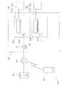
以下、設定値変更装置が携帯端末、さらに具体的には設定値変更装置がスマートフォンである場合を例に挙げて説明する。図1に示されているように、本発明の一実施形態に係る空気調和システム100は、携帯端末50を含んでいる。この携帯端末50は、具体的には、図3に示されているようなスマートフォン500である。 Hereinafter, a case where the setting value changing device is a mobile terminal, more specifically, a case where the setting value changing device is a smartphone will be described as an example. As shown in FIG. 1, an
(1)空気調和システムの概略構成
図1に、空気調和システム100の全体構成を示す。空気調和システム100は、情報仲介装置としてのサーバ40およびアダプタ20a,20bを介して、ユーザが保有する携帯端末50から所望の空気調和機10a,10bの情報を取得したり、所望の空気調和機10a,10bを操作したりするためのシステムである。(1) Schematic Configuration of Air Conditioning System FIG. 1 shows the overall configuration of the
インターネットを含む公衆回線80と、建物30内に敷設されているローカルエリアネットワーク(以下、LANという)81とを接続するルータ21が、建物30に設置されている。LAN81は、ルータ21の機能を利用した無線LANであり、空気調和機10a,10bに有線で接続されたアダプタ20a,20bが無線接続されている。なお、アダプタ20a,20bの他に、建物30内で使用される図示しないパソコン、プリンタ等のネットワーク機器がLAN81にさらに接続されていてもよい。 A
携帯端末50によるサーバ40を介した空気調和機10a,10bの管理をするためには、事前に各空気調和機10a,10bをサーバ40に登録しておく必要がある。なお、理解を容易にするため、図1には建物30を1つだけ示しているが、実際の空気調和システム100には、複数の建物30に散在する空気調和機10a,10bが含まれる。すなわち、公衆回線80によって建物30の遠隔に設置されているサーバ40は、空気調和機の製造会社や販売会社、あるいはメンテナンス会社によって運営されるものであり、多数の建物30内の空気調和機の情報がサーバ40内に蓄積されている。また、2台の空気調和機10a,10bと2台のアダプタ20a,20bは、建物30に設置される空気調和機とアダプタの設置例であって、例えば空気調和機の台数が1台であっても3台以上であってもよく、アダプタの台数も1台であっても3台以上であってもよい。 In order to manage the
(2)空気調和システムの詳細構成
(2−1)空気調和機
図1に示すように、空気調和機10a,10bは、建物30の各部屋30a,30bの中に設置される室内機11a,11bと、建物30の外に設置される室外機12a,12bとから構成されている。なお、室内機11a,11bは、後述するアダプタ20a,20bと1対1で接続されている。これら空気調和機10aと空気調和機10bとが基本構成を同じくすることから、空気調和機10aを例にとって以下の説明を行う。(2) Detailed Configuration of Air Conditioning System (2-1) Air Conditioner As shown in FIG. 1, the
室内機11aと室外機12aとは、冷媒配管を介して接続されており、図示しない圧縮機や熱交換器等から構成される冷媒回路を形成している。図2に示すように、空気調和機10aは、各種センサを有している。例えば、室内機11aは、室内機11aの設置されている部屋30aの温度を検出する室内温度センサ14aを有している。一方、室外機12aは、建物30付近の外気の温度を検出する外気温度センサ14bを有している。 The
また、空気調和機10aは、制御部13を有している。制御部13は、空気調和機10aに含まれる室内機11aおよび室外機12aの制御ユニットから構成されている。制御部13は、リモートコントローラ15を介して部屋30aに居るユーザから入力される空気調和機10aに対する運転指令に従って、空気調和機10aの運転を制御する、すなわち、冷媒回路に含まれる圧縮機等の動作を制御する。 In addition, the
また、制御部13は、空気調和機10aに関する機器データ25aをアダプタ20aに送信する。例えば、制御部13は、リモートコントローラ15を介して入力された室内機11aに対する制御指令の内容を示すデータを、アダプタ20aに送信する。運転指令の内容を示すデータとは、空気調和機10aの運転開始/運転停止、運転モード(冷房モード、暖房モード、送風モードなど)、設定温度、などである。アダプタ20aに送られる機器データ25aには、後述する保有機能情報18a、積算運転時間18b、消費電力18cなども含まれている。 Moreover, the
また、制御部13は、室内温度および外気温度に関する温度データ25bを、さらにアダプタ20aに送信する。具体的には、制御部13は、室内温度センサ14aによって検出された室内温度データ、および外気温度センサ14bによって検出された外気温度データを、アダプタ20aに送信する。 Moreover, the
また、制御部13は、アダプタ20aから送信されてくる制御指令を実行する。アダプタ20aから送信されてくる制御指令とは、例えば、室内機11aに対する運転指令や、特定の機器データをアダプタ20aに送信するよう命じる指令である。 The
制御部13は、CPUの他に、RAM及びROMを含む記憶部18を備えている。記憶部18には、ROMに記憶された保有機能情報18a、RAMに記憶された積算運転時間18b及び消費電力18cなどが存在している。積算運転時間18bは、タイマ17によりカウントされた空気調和機10aの累積の運転時間である。消費電力18cは、電力計14dによって計測された空気調和機10aの消費した電力である。 The
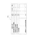
保有機能情報18aは、空気調和機10aが保有する機能に関する情報である。保有機能情報18aは、図4に示すように、空気調和機が備え得る多数の機能のうち、その空気調和機10aが実際に保有している機能、保有していない機能を区別した情報である。空気調和システム100においては、保有機能情報18aが、第1情報(図4の記号XX1)、第2情報(図4の記号XX2)、第3情報(図4の記号XX3)、第4情報(図4の記号XX4)および第5情報(図4の記号XXX)を含んでいる。例えば、第1情報は、積算運転時間を計測する時間計測機能を空気調和機10aが有しているか否かの情報である。図4に示す保有機能情報18aによれば、空気調和機10aは、洗濯物乾燥運転を行う機能と、遠隔操作による風向き変更機能と、人検知機能は備えておらず、積算運転時間の計測機能及び消費電力の計測機能を備えていることがわかる。上述のように、保有機能情報18aは、機器データ25aの一部としてアダプタ20aに送られ、アダプタ20aの記憶部24aに記憶される。 The
(2−2)情報仲介装置
情報仲介装置は、公衆回線80を利用して、空気調和機10a,10bと携帯端末50との間で情報のやりとりを行わせるための装置である。空気調和システム100では、情報仲介装置が、アダプタ20a,20b、ルータ21、およびサーバ40から構成されている。(2-2) Information Mediating Device The information mediating device is a device for exchanging information between the
(2−2−1)アダプタ
アダプタ20a,20bは、空気調和機10a,10bをLAN81に接続するためのネットワークアダプタである。アダプタ20aとアダプタ20bとが構成を同じくすることから、アダプタ20aを例にとって以下の説明を行う。(2-2-1) Adapter The
アダプタ20aは、図2に示すように、CPUの他に、無線通信部22aや記憶部24aを有している。アダプタ20aは、ネットワーク間での通信プロトコルの相違を吸収する通信機能の他、空気調和機10a,10bを制御する制御機能を有している。アダプタ20aは、室内機11aの制御部13と有線で接続されており、また図示は省略しているが室内機11aから電源を受けて作動する。 As shown in FIG. 2, the
記憶部24aには、機器データ25a及び温度データ25bなどが記憶されている。上述のように、これらのデータ25a,25bは、空気調和機10aからアダプタ20aに送信されてくる空気調和機10aに関するデータである。そして、アダプタ20aは、定期的に(ここでは1分毎に)、それらのデータ25a,25bを空気調和機10aの情報としてまとめ、公衆回線80を介してサーバ40に送信している。
また、記憶部24aには、サーバアドレスが予め記憶されている。さらに、記憶部24aには、サーバ40によってアダプタ20aに対して割り当てられた機器IDも記憶される。アダプタ20aの識別符号である機器IDは、サーバ40でアダプタ20aを一意に識別する情報となる。 In addition, a server address is stored in advance in the
(2−2−2)ルータ
ルータ21は、WAN側のインターフェースと、LAN側のインターフェースとを有し、両ネットワークを相互接続させる通信機器である。ルータ21は、アダプタ20a,20bがLAN81に接続されると、アダプタ20a,20bの存在を自動的に検出し、アダプタ20a,20bのネットワーク情報の登録を行う。これにより、アダプタ20a,20bは、LAN81内の他のネットワーク機器、および公衆回線80上(インターネット上)のネットワーク機器との通信が可能になる。この空気調和システム100においては、ルータ21が建物30内のLAN81を構築する役割も果たしている。(2-2-2) Router The
(2−2−3)サーバ
サーバ40は、空調管理サービスを行うために公衆回線80上(インターネット上)に設けられた、サーバソフトウェアを稼働させるコンピュータである。図3に示すように、サーバ40は、記憶部43を有している。(2-2-3) Server The
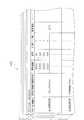
記憶部43には、空気調和機10a,10bに関する各種データを蓄積するためのデータベースが存在する。具体的には、記憶部43には、アダプタ別データベース43aが存在する。サーバ40は、アダプタ20aから定期的に送られてくる空気調和機の機器データ25a及び温度データ25bなどを、アダプタ別に蓄積している。このアダプタ別データベース43aでは、図5に示すように、空気調和機10a,10bに関する各種データが、それらの空気調和機10a,10bに接続されているアダプタ20a,20bに割り当てられた機器IDに関連付けられた態様で格納されている。 The
なお、アダプタ別データベース43aでは、アダプタの接続された空気調和機の情報が、そのアダプタとは異なる関連アダプタが接続されている空気調和機の情報と一緒に、1つのレコードとして格納されている。例えば、後述するように、同じ携帯端末50から初期設定がなされた2つのアダプタ20a,20bがあるときに、両アダプタ20a,20bは相互に関連する関連アダプタであるとサーバ40は認識する。 In addition, in the
また、アダプタ別データベース43aには、空気調和機10a,10bのユーザによる各種設定情報も格納されている。登録された空気調和機10a,10bが接続されているアダプタ20a,20bの機器ID、空気調和機10a,10bに対してユーザが任意で設定した機器名称、空気調和機10a,10bが保有する機能に関する保有機能情報18a、空気調和機10a,10bの設定温度、空気調和機10a,10bの外部からの操作の可否(ON/OFF)、空気調和機10a,10bのユーザに割り当てられているログインIDおよびパスワードを含むユーザの個人情報、などが1つのレコードとして格納されている。パスワードは、ユーザが公衆回線80経由でサーバ40にログインIDを使ってログインする際のログイン権限を認証するためのものである。 The adapter-
サーバ40は、空調管理アプリケーション54を実行しているユーザの携帯端末50からの要求に応じて、アダプタ別データベース43aに格納されている各種データを、公衆回線80を介してユーザの携帯端末50に送信する。 In response to a request from the
また、サーバ40は、公衆回線80を介して携帯端末50から受信した空気調和機10a,10bを操作するための操作コマンドを、アダプタ20a,20bからのアクセスがあったときにアダプタ20a,20bへ送信する。 Further, the
(2−3)携帯端末
携帯端末50は、空気調和機10a,10bのユーザが携帯するものであって、例えば、携帯電話、スマートフォン、タブレットコンピュータ、ノート型パソコンなどの可搬性のコンピュータ、が挙げられる。以下、携帯端末50としてスマートフォン500が採用された場合を例にとって説明する。(2-3) Portable terminal The
図3に示すように、スマートフォン500は、CPU、第1無線通信部51a、第2無線通信部51b、記憶部53などを含む制御装置52のほか、入出力機能を担うタッチスクリーン装置55を備えている。第1無線通信部51aは、公衆回線80への接続機能を有している。第2無線通信部51bは、Wi−Fi(登録商標)による無線通信を行うもので、建物30内において公衆回線80を介さずにLAN81を介してアダプタ20a,20bに接続する役割を果たす。タッチスクリーン装置55は、表示画面として機能するとともに、操作ボタンとしての機能を果たす。操作ボタンは、表示画面上に表示された画像中に含まれるボタンである。 As shown in FIG. 3, the
スマートフォン500には、スマートフォン500によって空気調和機10a,10bを管理するための空調管理アプリケーション54が搭載されている。空調管理アプリケーション54は、ユーザが、公衆回線80を介してサーバ40からダウンロードする。ユーザは、空調管理アプリケーション54によって生成されタッチスクリーン装置55に提供される画像を介して、空気調和機10a,10bの情報を監視したり、空気調和機10a,10bの操作を行ったりすることができる。この空調管理アプリケーション54は、接続先であるサーバ40のインターネット上のアドレスを最初から保持している。 The
(3)初期設定
空気調和システム100は、空気調和機10a,10bにアダプタ20a,20bを接続し、アダプタ20a,20bをルータ21に認識させ、上述のようにユーザが空調管理アプリケーション54をダウンロードしてスマートフォン500にインストールし、さらに自宅などの建物30内でユーザが初期設定を行うことによって使えるようになる。(3) Initial setting The
空気調和機10a,10bにアダプタ20a,20bを接続すると、アダプタ20a,20bは、まず、機器データ25a及び温度データ25bなどの空気調和機10a,10bの情報を取得し、その記憶部24aに記憶する。次に、アダプタ20a,20bの無線接続設定の機能を使い、ユーザがアダプタ20a,20bをルータ21に認識させ、LAN81にアダプタ20a,20bを接続させる。 When the
次に、ユーザは、建物30内において、スマートフォン500にインストールした空調管理アプリケーション54を立ち上げる。すると、空調管理アプリケーション54を実行しているスマートフォン500(以下、単に空調管理アプリケーション54という)は、第2無線通信部51bおよびルータ21を介して、LAN81に接続されているアダプタ20a,20bを探し、その一覧を図6(a)に示すようにタッチスクリーン装置55に表示する。 Next, the user starts up the air
図6(a)に示す画面上でユーザが「未設定1」の機器のアイコンをタップして「編集」ボタン56aを押すと、機器名称や設置場所の入力、その他の設定を行うための次画面(図6(b)参照)が表示される。ここで、例えば、空気調和機10aについて、機器名称として「Living」といった入力を行うと、次からは空気調和機の一覧画面において「未設定1」の代わりに「Living」と表示される。 When the user taps the “unset 1” device icon on the screen shown in FIG. 6A and presses the “edit”
また、図6(b)に示す「外から操作設定」を選択し、その設定を「OFF」から「ON」に変更すると、その空気調和機を建物30の外から操作するための初期設定を行うように、空調管理アプリケーション54がユーザに操作を促す。ここで、ユーザは、ログインIDとパスワードを設定する。同じLAN81上の2つ以上のアダプタ20a,20bがあると空調管理アプリケーション54が認識をしている場合、ユーザは、それらのアダプタ20a,20bを同じログインIDおよびパスワードで管理することができる。同じ設定にした場合、外から空気調和機10a,10bを監視、操作するときに、空気調和機一覧画面において複数の機器が表示され選択可能とされる。 Further, when “operation setting from outside” shown in FIG. 6B is selected and the setting is changed from “OFF” to “ON”, initial setting for operating the air conditioner from outside the
ログインIDおよびパスワードの設定が為されると、アダプタ20a,20bは、ルータ21を介して、自動的にサーバ40にアクセスする。このときに、アダプタ20a,20bは、自身を特定する情報をサーバ40に送信する。サーバ40は、そのアダプタ20a,20bからのアクセスを受けたときに、上述のように、アダプタ20a,20bに機器IDを割り当て、その機器IDによってアダプタ別データベース43aにレコードを付け加える。アダプタ20a,20bは、サーバ40から機器IDが送信されてくると、その自身の機器IDを記憶部24aに記憶する。次に、アダプタ20a,20bは、サーバ40からの要求に応じて、記憶部24aにある保有機能情報18aを含む空気調和機10a,10bの情報をサーバ40に送信する。サーバ40は、アダプタ20a,20bから送られてきた空気調和機10a,10bの情報を、アダプタ20a,20bの機器IDに関連づけた形で記憶部43のアダプタ別データベース43aに入れる。サーバ40は、ユーザが最初にスマートフォン500で外からログインIDおよびパスワードを使ってアクセスしてきたときに、アダプタ20a,20bに対して空気調和機10a,10bの情報を要求する。 When the login ID and password are set, the
なお、アダプタ別データベース43aの機器ID別の各レコードは、そのアダプタ20a,20bの設定を行った空調管理アプリケーション54においてユーザが決めたログインIDおよびパスワードとも関連づけられている。そして、同じログインIDおよびパスワードで管理される複数のアダプタ20a,20bに関しては、サーバ40のアダプタ別データベース43aにおいて、機器ID毎のレコードを図5に示すように1つのレコードにまとめて保存してもよい。 Each record of each adapter ID in the
初期設定後、ユーザがスマートフォン500で空調管理アプリケーション54を起動すると、ログインIDおよびパスワードの入力箇所を含む初期画面がスマートフォン500のタッチスクリーン装置55に表示される。このとき、ユーザは、初期画面に含まれるログインIDおよびパスワードの入力箇所に、提供されたログインIDおよび設定したパスワードを入力しなければ、空調管理アプリケーション54によってサーバ40の記憶部43に保存されている空気調和機10a,10bの情報を見たり空気調和機10a,10bを操作したりすることができない。このようにして、空気調和システム100では、不正な遠隔操作を防止している。 After the initial setting, when the user starts the air
(4)空調管理アプリケーションを用いた外部からの空気調和機の監視、操作
空調管理アプリケーション54は、種々の機能を有しているが、基本的な機能部として、空調機情報要求部54a、空調機情報取得部54b、管理画面生成部54c及び管理画面検知エリア決定部54dを備えている。(4) Monitoring and operation of an air conditioner from the outside using an air conditioning management application The air
建物30の外部において、スマートフォン500の空調管理アプリケーション54が起動され、ユーザによってログインIDおよびパスワードが入力されると、空調機情報要求部54aが、ログインIDに関連づけられた全てのアダプタ20a,20bに接続されている空気調和機10a,10bの情報を、第1無線通信部51aを介してサーバ40に要求する。かかる情報送信要求を受けて、サーバ40は、アダプタ別データベース43aからログインIDに関連づけられているアダプタ20a,20bが接続された空気調和機10a,10bに関する各種データを、スマートフォン500に送信する。この空気調和機10a,10bに関する各種データには、保有機能情報18aを含む機器データ25a及び、設定温度などの温度データ25bなどが含まれている。 When the air
この空気調和機10a,10bに関するデータは、空調管理アプリケーション54の空調機情報取得部54bにて受信され、スマートフォン500のメモリに一時的に記憶される。保有機能情報18aなどの空気調和機10a,10bに関するデータに基づいて、空調管理アプリケーション54の管理画面生成部54cが、タッチスクリーン装置55に表示させる監視・操作用の空気調和機管理画面を生成する。そして、保有機能情報18aなどの空気調和機10a,10bに関するデータに基づいて、空調管理アプリケーション54の管理画面検知エリア決定部54dが、空気調和機管理画面に対応させて、タッチスクリーン装置55の画面への接触を検知する検知エリアを決定する。 The data related to the
タッチスクリーン装置55は、図3に示されているように、ディスプレイ551とタッチセンサ552とを備えている。制御装置52は、管理画面生成部54cによってタッチスクリーン装置55のディスプレイ551を制御し、タッチスクリーン装置55の表示機能を制御している。また、制御装置52は、管理画面検知エリア決定部54dによってタッチスクリーン装置55のタッチセンサ552を制御し、タッチスクリーン装置55の入力機能を制御している。 As shown in FIG. 3, the
具体的には、スマートフォン500の空調管理アプリケーション54が起動されると、まず、監視や操作が可能な空気調和機10a,10bの一覧画像が表示される。そして、ユーザが、タッチスクリーン装置55上の一覧画像に含まれる例えば空気調和機10aのアイコンを1つタップすると、例えば図7に示すような「Living」の空気調和機10aの監視・操作用の空気調和機管理画面が表示される。 Specifically, when the air
管理画面生成部54cは、記憶部53に一時記憶されている空気調和機10aに関するデータを参照し、機器名称が「Living」であるという情報を表示するための機器名称エリア57aの表示画像を生成する。また、管理画面生成部54cは、記憶部53に一時記憶されている空気調和機10aに関するデータを参照し、28℃という室内温度、30℃という室外温度、50%という室内湿度、及び3.0kWという瞬時消費電力を、空気調和機10a,10bに関する情報として表示するために、第1情報エリア57bの表示画像を生成する。また、空気調和機10aに設定されている設定温度を表示する第2情報エリア57cの表示画面を生成する。 The management
さらに、管理画面生成部54cは、記憶部53に一時記憶されている空気調和機10aに関するデータを参照し、空気調和機10aの運転を開始させるための運転ボタン55a、空気調和機10aの運転を停止させるための停止ボタン55b、空気調和機10aの運転モードを切り換えるための複数の運転モードボタン55c、設定温度を連続的に変更可能なドラッグ式の温度設定ボタン55d、温度設定ボタン55dが移動する移動経路55e、設定温度を上昇させるプラスボタン55f、設定温度を下降させるマイナスボタン55g、高温/消し忘れ通知の表示画面に遷移するための高温/消し忘れ通知ボタン55h、湿度を調整する加湿を行わせるための湿度調整ボタン55i、及び前の表示画面に戻るためのバックボタン55jなどの表示画面を生成する。 Furthermore, the management
上述の各種ボタンの表示画面を生成する際に、管理画面生成部54cは、例えばボタンの色及び/又は輝度を変化させることで異なる情報をユーザに提供することができる。管理画面生成部54cは、空気調和機10aの運転が行なわれているか又は運転が停止しているかを表示するために運転ボタン55aと停止ボタン55bの例えば色及び/又は輝度を変え、或いは空気調和機10aの現在のモードを表示するために運転モードボタン55cの中の現在のモードに対応する箇所の例えば色及び/又は輝度を変える。 When generating the display screen of the various buttons described above, the management
なお、管理画面生成部54cは、その「Living」の空気調和機10aの保有機能情報18aに応じて、空気調和機画面の構成を変える場合がある。例えば、図7に示す空気調和機管理画面では、「Living」の空気調和機10aに高温/消し忘れ通知機能が備わっていることを図4の保有機能情報18aが示す場合には、高温/消し忘れ通知の表示画面に遷移するための高温/消し忘れ通知ボタン55hが表示されるが、保有機能情報18aが高温/消し忘れ通知機能が空気調和機10aに備わってないことを示す場合に、管理画面生成部54cは、高温/消し忘れ通知ボタン55hの無い表示画面を生成する。 The management
管理画面生成部54cが生成した上述の各種ボタンの配置位置に対応させて、管理画面検知エリア決定部54dは、検知エリアを設定する。管理画面検知エリア決定部54dは、例えば、運転ボタン55aの表示位置に重なる場所に運転入力検知エリア58aを配置し、停止ボタン55bの表示位置に重なる場所に停止入力検知エリア58bを配置し、複数の運転モードボタン55cの表示位置にそれぞれ重なる場所に複数のモード入力検知エリア58cを配置し、温度設定ボタン55dの表示位置に重なる場所に温度変更入力検知エリア58dを配置し、プラスボタン55fの表示位置に重なる場所に温度上昇入力検知エリア58fを配置し、マイナスボタン55gの表示位置に重なる場所に温度下降入力検知エリア58gを配置し、高温/消し忘れ通知ボタン55hの表示位置に重なる場所に通知要求入力検知エリア58hを配置し、湿度調整ボタン55iの表示位置に重なる場所に加湿入力検知エリア58iを配置し、バックボタン55jの表示位置に重なる場所に画面変更入力検知エリア58jを配置する。 The management screen detection
そして、空調管理アプリケーション54は、タッチスクリーン装置55のタッチセンサ552の空気調和機管理画面を介して、ユーザから空気調和機10aの操作入力を受け付ける。ユーザが、図7に示す空気調和機管理画面において、停止ボタン55bが押されると、タッチセンサ552によって、停止入力検知エリア58bに接触があったことが検知される。スマートフォン500の制御装置52は、停止入力検知エリア58bに接触があったことがタッチセンサ552で検知されると、「Living」の空気調和機10aを運転状態から停止状態にする操作コマンドをサーバ40に送る。「Living」の空気調和機10aを運転状態から停止状態にする操作コマンドを受信したサーバ40は、アダプタ20aがアクセスしてきたときに操作コマンドをアダプタ20aに送る。操作コマンドを受け取ったアダプタ20aは、その操作コマンドに合った指令、すなわちここでは停止指令を空気調和機10aに送る。 The air
逆に、「Living」の空気調和機10aが停止状態にあるときに、空気調和機管理画面において運転ボタン55aが押されると、タッチセンサ552によって、運転入力検知エリア58aに接触があったことが検知される。スマートフォン500の制御装置52は、運転入力検知エリア58aに接触があったことがタッチセンサ552で検知されると、「Living」の空気調和機10aを停止状態から運転状態にする操作コマンドをサーバ40に送る。同様に、他の運転モードボタン55c、プラスボタン55f、マイナスボタン55g、高温/消し忘れ通知ボタン55h、湿度調整ボタン55i又はバックボタン55jなどを押す入力操作をユーザが行うと、タッチセンサ552の検知エリアに重なっているボタンに対応する操作コマンドが、空調管理アプリケーション54からサーバ40に送られる。 Conversely, when the
なお、温度設定ボタン55dに係るドラッグ式の入力操作については、後ほど詳細に説明する。 The drag type input operation related to the
(5)空調管理アプリケーションを用いた建物内からの空気調和機の監視、操作
建物30の内部において、スマートフォン500の空調管理アプリケーション54が起動され、ユーザによってログインIDおよびパスワードが入力されると、空調機情報要求部54aが、アダプタ20a,20bに接続されている空気調和機10a,10bの情報を、第2無線通信部51bを介してアダプタ20a,20bに要求する。かかる情報送信要求を受けて、アダプタ20a,20b、記憶部24aに記憶されている空気調和機10a,10bに関する各種データを、スマートフォン500に送信する。この空気調和機10a,10bに関する各種データには、保有機能情報18aを含む機器データ25a、設定温度などの温度データ25b、などが含まれている。(5) Monitoring and operation of the air conditioner from the building using the air conditioning management application When the air
その後の、監視・操作用の空気調和機管理画面の生成までは、建物30の外部におけるスマートフォン500の空調管理アプリケーション54の動作と同じである。 Subsequent generation of the monitoring / operation air conditioner management screen is the same as the operation of the air
また、ユーザからの空気調和機10a,10bの操作入力の受け付けまでは、建物30の外部におけるスマートフォン500の空調管理アプリケーション54の動作と同様である。但し、建物30の内部においては、操作コマンドが、スマートフォン500から第2無線通信部51bを介してアダプタ20a,20bに送信される。スマートフォン500から操作コマンドを直接受け取ったアダプタ20a,20bは、その操作コマンドに合った指令を空気調和機10a,10bに送る。 The operation from the user to the operation input of the
(6)ドラッグ操作による設定温度の変更
(6−1)温度変更入力検知エリアとキャンセルエリア
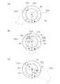
制御装置52は、空調管理アプリケーション54の管理画面生成部54cによって、図9(a)、図9(b)及び図9(c)に示されているように、設定温度の値に応じて温度設定ボタン55dの位置を変えた表示画像を生成する。図9(a)乃至図9(c)に示されているのは冷房運転モードにおける表示の一例である。空気調和機10aは、冷房運転モードにおいて、18℃から30℃までの範囲で設定温度を変更できるものとなっている。このような空気調和機10aでは、管理画面生成部54cは、例えば、設定温度が18℃のときは、移動経路55eを反時計回りに回り切ったところにある移動経路55eの第1端部59aに温度設定ボタン55dが描かれた画面を表示し(図9(a)参照)、設定温度が30℃のときは、移動経路55eを時計回りに回り切ったところにある移動経路55eの第2端部59bに温度設定ボタン55dが描かれた画面を表示し(図9(c)参照)、設定温度が24℃のときは、移動経路55eの第1端部59aと第2端部59bの中間にある中央部59cに温度設定ボタン55dが描かれた画面を表示する(図9(b)参照)。空気調和機10aが1℃刻みで温度設定が可能であれば、19℃から23℃までの間は設定温度の値が1℃大きくなる毎に温度設定ボタン55dの位置が第1端部59aよりも中央部59cに近づいた画面が管理画面生成部54cによって表示される。また、24℃から30℃までの間は設定温度の値が1℃大きくなる毎に温度設定ボタン55dの位置が中央部59cよりも第2端部59bに近づいた画面が管理画面生成部54cによって表示される。(6) Change of set temperature by dragging operation (6-1) Temperature change input detection area and cancellation area The
図9(a)乃至図9(c)に示されている表示画面において、温度設定ボタン55dにタッチされる前には、管理画面検知エリア決定部54dが、温度設定ボタン55dと重なる場所に温度変更入力検知エリア58dの配置を決定する。従って、移動経路55eのうちの温度設定ボタン55dが描かれている以外のところをタッチしても、温度設定操作コマンドに合った指令が送信されることはない。 In the display screens shown in FIGS. 9A to 9C, before the
制御装置52は、温度設定ボタン55dがタッチ操作されると、つまり温度変更入力検知エリア58dに対する接触が検知されると、図10に示されているように、温度変更入力検知エリア58dを拡大する。この拡大は、移動経路55e内の温度設定ボタン55dと実質的に同じ大きさであった温度変更入力検知エリア58dを移動経路55eよりも大きくすることである。拡大された温度変更入力検知エリア58dは、温度変更入力検知エリア58dへの接触が続いている限りにおいて拡大されたままの状態が維持される。言い換えると、制御装置52は、温度設定ボタン55dがドラッグ操作されている限りにおいて、図10のような拡大された温度変更入力検知エリア58dを維持する。この明細書で「ドラッグ操作」というときは、ディスプレイ551の画面のドラッグ操作に対応したボタンに接触した後、接触したままの状態を保って移動するスワイプ操作を行い、画面への接触が解除されるまでの操作を意味する。従って、タッチ操作(又はタップ操作ともいう)のみに対応するボタンつまりタッチしたことは検知できるが移動したことは検知できないボタンに対して接触したままの状態を保って移動するスワイプ操作を行っても、そのような操作はドラッグ操作ではない。また、ドラッグ操作に対応したボタンを「ドラッグボタン」と呼ぶ。また、ドラッグ操作が可能なエリアをドラッグエリアと呼ぶ。 When the
従って、温度変更入力検知エリア58dがプラスボタン55f及びマイナスボタン55gと重なるくらいに拡大されるので、もはやプラスボタン55f及びマイナスボタン55gと重なる場所には温度上昇入力検知エリア58f及び温度下降入力検知エリア58gが存在しなくなるので、温度設定ボタン55dのドラッグ操作においてプラスボタン55f又はマイナスボタン55gの場所まで例えば指がスライドしたとしてもプラスボタン55f又はマイナスボタン55gに対するタップ操作が無視されて温度設定ボタン55dのドラッグ操作が継続される。同様に、例えば温度変更入力検知エリア58dが運転モードボタン55cと重なるくらいに拡大されるので、もはや運転モードボタン55cと重なる場所にはモード入力検知エリア58cが存在しなくなる。従って、温度設定ボタン55dのドラッグ操作において運転モードボタン55cの場所まで例えば指がスライドしたとしても運転モードボタン55cに対するタップ操作が無視されて温度設定ボタン55dのドラッグ操作が継続される。 Therefore, since the temperature change
また、図10に示されているように、制御装置52は、円弧状の移動経路55eの中心に基点BP1を設定する。さらに、制御装置52の管理画面検知エリア決定部54dは、基点BP1と、移動経路55eの第1端部59aと第2端部59bとを結ぶ線分LS2の中点MPとを結ぶ線分LS1の上にキャンセルエリア60を設定する。キャンセルエリア60は、線分LS1に沿って細長く延びている。キャンセルエリア60は、線分LS1に沿う方向の長さが線分LS2の延びる方向(線分LS1と直交する方向)の幅よりも大きく設定される。また、移動経路55eとキャンセルエリア60との間の隙間CL1の長さは、例えば、移動経路55eの内径D1の30%である。この隙間CL1は、大きすぎると予期しない値が温度設定値として設定されるのを防ぐ効果を小さくさせ、小さすぎると通常の温度設定値の変更操作の妨げとなることから、例えば20%から40%の範囲で設定される。 Further, as shown in FIG. 10, the
(6−2)ドラッグ操作
温度設定ボタン55dについての基本的なドラッグ操作は、図11(a)、図11(b)及び図11(c)に示されている。ユーザが指200で温度設定ボタン55dをタッチする(図11(a)参照)。指200で温度設定ボタン55dに触れたままで、指200を移動経路55eに沿って移動させる。なお、図11(b)において、破線で示された温度設定ボタン55dは、指200の移動を開始した時点のものである。管理画面生成部54cは、温度設定ボタン55dを指200が接触しているドラッグ操作位置に描き直すように画面を次々に生成する。指200が接触している位置に温度設定ボタン55dが描き直されることで、ユーザには、温度設定ボタン55dが移動経路55eの上を指200によってスライドされているように見える。図11(b)には図示が省略されているが、管理画面生成部54cは、温度設定ボタン55dの位置つまりは指200のドラッグ操作位置に対応した設定温度の値を移動経路55eに囲まれた領域に表示させる。また、指200が放れた時点を境として、図10のような温度変更入力検知エリア58dが拡大された状態から図8のような温度変更入力検知エリア58dが小さい通常の状態になるように、温度変更入力検知エリア58dが縮小される。(6-2) Drag Operation The basic drag operation for the
ユーザは所望の設定温度の値が表示された場所で、温度設定ボタン55dから指200を放す(図11(c)参照)。温度設定ボタン55dから指200を放すことによって、設定温度の値が確定する。設定温度の値は、温度設定ボタン55dから指200が放されたところの位置に対応する値になる。例えば、指200が放された位置が移動経路55eの中央部59cであれば、設定温度が24℃に変更される。 The user releases the
次に、移動経路55eから外れたところに指200が移動された場合について説明する。先ず、図12を用いて、指200が移動経路55eを外れてドラッグ操作された場合であって且つキャンセルエリア60を指200が横切らなかった場合の入力操作について説明する。最初は、図12の破線で示された温度設定ボタン55dの位置で指200がタッチされた。その後、基本的な移動経路55eに沿った指200のスライドではなく、指200が矢印Ar1に沿って移動し、ドラッグ操作位置P1が移動経路55eから外れたところに止まった。このような場合、温度変更入力検知エリア58dがキャンセルエリア60を除く図12の全体に広がっていることから、ドラッグ操作位置P1も温度変更入力検知エリア58dの範囲内にある。従って、ドラッグ操作位置P1で指200が止まっても指200がディスプレイ551の画面をタッチしているのでドラッグ操作が継続している。 Next, a case will be described in which the
図12のようにドラッグ操作位置P1で指200が止まると、制御装置52は、ドラッグ操作位置P1と基点BP1とを直線SS1で結ぶ。そして、制御装置52は、直線SS1と移動経路55eとの交点に、指200によって温度設定ボタン55dが移動されたものとみなす。言い換えると、制御装置52は、ドラッグエリアである温度変更入力検知エリア58におけるドラッグ操作位置P1と基点BP1とを結ぶ直線が移動経路55eと交わる交点CP1にドラッグボタンである温度設定ボタン55dを移動するとともに温度設定ボタン55dの位置に対応する値に設定温度の値を変更する。このような動作によって、変更された温度設定値を確定するには、ドラッグ操作位置P1で指200をディスプレイ551の画面から放せばよい。また、さらに異なる値に温度設定したいときには、ドラッグ操作位置P1から指200を放さずにスワイプ操作を続ければよい。 When the
図12に矢印Ar1を用いて説明した例では、指200のドラッグ操作が移動経路55eの外側に外れる場合について説明したが、移動経路55eの内側に外れる場合でも同様の動作が行われる。例えば、図12の矢印Ar2のように指200がスワイプ操作してドラッグ操作位置P2で指200が停止した場合も、上述の矢印Ar1のようにスワイプ操作された場合と同様の温度設定値になる。つまり、基点BP1からドラッグ操作位置P2を通って延びる直線SS1を引いて、直線SS1と移動経路55eの交点CP1に温度設定ボタン55dが移動された場合の設定温度の値がドラッグ操作位置P2に指200があるときの値になる。移動経路55eの内側にドラッグ操作位置P2がある場合も、ドラッグ操作位置P2で指200をディスプレイ551の画面から放すと、温度設定ボタン55dの位置に対応する値に設定温度の値が確定する。 In the example described using the arrow Ar1 in FIG. 12, the case where the drag operation of the
次に、図13(a)、図13(b)及び図13(c)を用いて、指200が移動経路55eを外れてドラッグ操作された場合であって且つキャンセルエリア60を指200が横切った場合の入力操作について説明する。図13(a)には、制御装置52が、管理画面生成部54cにより、ドラッグボタンである温度設定ボタン55d及び移動経路55eをディスプレイ551に表示させた状態が示されている。また、図13(a)に示されている状態は、温度設定ボタン55dに指200でタッチ操作がされて、制御装置52が、管理画面検知エリア決定部54dにより、移動経路55e以外の場所に配置された基点BP1を設け、ドラッグエリアである温度変更入力検知エリア58dを移動経路55eの表示範囲よりも大きく設定した状態である。また、制御装置52は、管理画面検知エリア決定部54dにより、キャンセルエリア60も設定している。図13(a)に示されている温度設定ボタン55dの位置が現在の設定温度の値に対応している。 Next, using FIG. 13A, FIG. 13B, and FIG. 13C, the
次に、図13(b)に示されているように、ユーザの指200は、矢印Ar3の示される軌跡を描いて移動経路55eよりも基点BP1に近い側に外れてドラッグ操作位置P3までスワイプされている。図13(b)に示されている状態は、まだドラッグ操作の最中であるが、既に説明したように、ドラッグ操作位置P3と基点BP1を結ぶ直線SS2と移動経路55eとの交点に温度設定ボタン55dが移動している。 Next, as shown in FIG. 13B, the user's
例えば、図13(b)に示されている状態で、ユーザがドラッグ操作を終了するために指200をディスプレイ551の画面から放そうと考えたとする。ところが、実際には操作を誤って、矢印Ar4で示される軌跡を描いてディスプレイ551の画面の上をスワイプしてしまい、ドラッグ操作位置P4で画面から指200が放れたとする。このような誤操作を行った場合、もしキャンセルエリア60が設定されていなければ、ドラッグ操作位置P4と基点BP1を結ぶ直線SS3の上に二点鎖線で示したように、温度設定ボタン55dが移動することになる。この二点鎖線で示された温度設定ボタン55dの位置に対応する設定温度の値はユーザが設定したかった温度に比べてかなり大きな温度になる。このような状態でユーザが設定温度の確認を怠ると、空気調和機10aにより実際の室内がユーザの意図しない高い温度に維持されることになる。 For example, in the state shown in FIG. 13B, it is assumed that the user considers releasing the
しかし、図13(c)に示されているように、キャンセルエリア60が設定されているため、制御装置52は、矢印Ar4とキャンセルエリア60とが交わるところで、ドラッグ操作が終了したと判断し、言い換えれば矢印Ar4とキャンセルエリア60とが交わるところで指200がディスプレイ551の画面から放れたとみなす判断をする。その結果、図13(c)に示されている場合には、ユーザの誤操作によっては温度設定ボタン55dがほとんど移動せず、ユーザの誤操作によってユーザの設定したかった設定温度の値から大きく外れた値が設定温度として設定されるのを防止することができる。 However, as shown in FIG. 13C, since the cancel
(7)変形例
(7−1)変形例1A
上記実施形態では、冷凍装置の温度設定値を変更する設定値変更装置として、空気調和システム100の携帯端末50であるスマートフォン500を例に挙げて説明した。しかし、本発明に係る設定値変更装置が変更するものは、冷凍装置の温度設定値以外に給湯装置の湯量設定値でもよい。ここでは、給湯装置の湯量設定値の変更について、図14及び図15を用いて説明する。(7) Modification (7-1) Modification 1A
In the said embodiment, the
(7−1−1)給湯システムの概要
給湯システムは、給湯を行うか否か、浴槽の湯張りを行うか否か、浴槽の湯の追い焚きを行うか否か、給湯温度の温度設定及び貯湯タンクに貯める湯の湯量設定などの情報の全部又は一部を、スマートフォン500を使って送受信することができるように構成されている。(7-1-1) Overview of Hot Water Supply System The hot water supply system determines whether or not to perform hot water supply, whether or not to refill the bathtub, whether to refill the hot water in the bathtub, the temperature setting of the hot water supply temperature, and All or part of information such as the hot water volume setting stored in the hot water storage tank can be transmitted and received using the
図14には、変形例1Aに係る給湯システム600の構成が示されえている。図14の給湯システム600は、住宅に設置されており、給湯装置602、台所用リモートコントローラ604、及び浴室用リモートコントローラ605で構成される。このような給湯システム600は、住宅の浴室に設置された浴槽681の浴槽吐出口682及び、台所等に設置された水栓685に温められた水を供給することができる。 FIG. 14 shows the configuration of hot
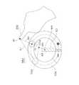
(7−1−2)給湯装置602の構成
給湯装置602は、ヒートポンプユニット621、貯湯タンク622及び第2水熱交換器623を有している。図15にはヒートポンプユニット621と貯湯タンク622の外観が示されている。ヒートポンプユニット621は、空気熱交換器625、圧縮機626、第1水熱交換器627及び膨張弁628を有しており、これらは順次接続されて冷媒回路を構成している。ヒートポンプユニット621は、空気熱交換器625において大気中の熱を汲み上げて冷媒に伝える。圧縮機626においては、冷媒が圧縮されて、高温化された冷媒が、第1水熱交換器627において配管629を流れる水に冷媒の熱を伝える。膨張弁628においては冷媒が減圧されて低温化され、低温化された冷媒が空気熱交換器625に送られる。(7-1-2) Configuration of Hot
貯湯タンク622内には水道源645から給水がされる。貯湯タンク622内に給水された水は、配管629に送られ、第1水熱交換器627で沸き上げられて湯となる。貯湯タンク622に貯湯された水(湯)は、給湯装置602を利用するユーザの要求に応じて、水栓685に提供されたり、浴槽681に提供されたりする。また、浴槽681内に貯められた水は、ユーザの要求に応じて、浴槽681の浴槽回収口683から浴槽循環路630を介して第2水熱交換器623に送られ、その後浴槽吐出口682を介して浴槽681内に戻される。この時、貯湯タンク622内の水は、貯湯タンク循環路640を介して第2水熱交換器623に送られた後、再度貯湯タンク622内に戻される。そのため、浴槽681内に貯められていた水は、第2水熱交換器623により貯湯タンク622内の高音の水と熱交換を行い、温められる(追い焚き動作)。 Water is supplied from a
ヒートポンプユニット621の本体ケーシング650内には、CPUやROM等で構成されるマイクロコンピュータからなる制御装置713が取り付けられている。制御装置713は、ヒートポンプユニット621内の各機能部の制御、貯湯タンク622内の水位センサ715及び温度センサ714の検知結果に基づいて沸き上げ動作、お湯はり動作及び追い焚き動作等の制御を行う。制御部13は、台所用リモートコントローラ604、浴室用リモートコントローラ605及びスマートフォン500を介してユーザから入力される給湯装置602に対する指令に従って、給湯装置602の運転を制御する、すなわち、冷媒回路に含まれる圧縮機626及び膨張弁628等の動作を制御する。また、制御装置713は、給湯装置602に関する情報を台所用リモートコントローラ604及び浴室用リモートコントローラ605に出力する。ここで、給湯装置602に関する情報としては、給湯装置602が湯張り動作や追い焚き動作等の各種動作を現在行っているか否かを示す情報、貯湯タンク622内の残湯量を示す情報、及び浴槽681内に貯められた湯の現在の温度及び湯量等が挙げられる。また、制御装置713は、給湯装置602に関する機器データ25aをアダプタ720に送信する。例えば、制御装置713は、リモートコントローラ604,605を介して入力された給湯装置602に対する制御指令の内容を示すデータを、アダプタ720に送信する。また、制御装置713は、アダプタ720から送信されてくる制御指令を実行する。アダプタ720から送信されてくる制御指令とは、例えば、給湯装置602に対する運転指令や、特定の機器データをアダプタ720に送信するよう命じる指令である。記憶部18には、保有機能情報18a及び積算運転時間18bなどが存在している。積算運転時間18bは、タイマ17によりカウントされた給湯装置602の累積の運転時間である。保有機能情報18aは、給湯装置602が保有する機能に関する情報である。保有機能情報18aは、機器データ25aの一部としてアダプタ720に送られ、アダプタ720の記憶部24aに記憶される。 Inside the
また、制御装置713は、温度データ25b及び湯量データ25cを、さらにアダプタ720に送信する。具体的には、制御装置713は、温度センサ714によって検出された温度データ、及び水位センサ715によって検出された湯量データを、アダプタ720に送信する。 Further, the
台所用リモートコントローラ604は、ユーザの利便性を考慮してユーザ宅の台所の側壁に取り付けられている。台所用リモートコントローラ604は、給湯装置602を遠隔制御するためのものであって、給湯装置602の制御装置713に接続されている。台所用リモートコントローラ604が有する機能としては、給湯を行うか否か、浴槽の湯張りを行うか否か、浴槽の湯の追い焚きを行うか否か、並びに給湯温度及び湯量設定値などを設定する設定機能、並びに湯張り動作の終了、追い焚き動作の終了及び貯湯タンク622の湯量変化などを知らせるためのガイダンス機能が挙げられる。 The kitchen
浴室用リモートコントローラ605は、台所用リモートコントローラ604と同様、給湯装置602を遠隔制御するためのものであって、住宅の浴室内の側壁に取り付けられている。また、浴室用リモートコントローラ605は、上述の設定機能及びガイダンス機能を有している。 Similar to the kitchen
(7−1−3)アダプタ
給湯システム600においては、電装部690にアダプタ720を内蔵している。アダプタ720は、給湯装置602をLAN81に接続するためのネットワークアダプタである。アダプタ720は、上述のアダプタ20a,20bと同様に構成することができる。アダプタ720は、給湯装置602を制御する制御機能を有している。アダプタ720は、給湯装置602の制御装置713と有線で接続されており、また図示は省略しているが給湯装置602から電源を受けて作動する。(7-1-3) Adapter In the hot
記憶部24aには、機器データ25a、温度データ25b及び湯量データ25cなどが記憶されている。上述のように、これらのデータ25a,25b,25cは、給湯装置602からアダプタ720に送信されてくる給湯装置602に関するデータである。そして、アダプタ720は、定期的に(ここでは1分毎に)、それらのデータ25a,25b,25cを給湯装置602の情報としてまとめ、公衆回線80を介して図17に記載されているサーバ40に送信している。 The
また、記憶部24aには、サーバアドレスが予め記憶されている。さらに、記憶部24aには、サーバ40によってアダプタ720に対して割り当てられた機器IDも記憶される。アダプタ720の識別符号である機器IDは、サーバ40でアダプタ720を一意に識別する情報となる。 In addition, a server address is stored in advance in the
給湯システム600も、空気調和システム100の情報仲介装置と同様に、アダプタ720、ルータ(図示せず)及びサーバ40を含む情報仲介装置を備えている。給湯システム600の情報仲介装置も、公衆回線80を利用して、給湯装置602と携帯端末であるスマートフォン500との間で情報のやりとりを行わせるための装置である。 The hot
(7−1−4)サーバ
サーバ40の記憶部43には、給湯装置602に関する各種データを蓄積するためのデータベースが存在する。アダプタ720に対応する記憶部43のアダプタ別データベース43aには、湯量に関する湯量データ25cが記憶されている。(7-1-4) Server The
(7−1−5)スマートフォン
図17に示すように、スマートフォン500の構成は、空気調和システム100と同様である。スマートフォン500には、スマートフォン500によって給湯装置602を管理するため、空調管理アプリケーション54に代えて給湯管理アプリケーション754が搭載されている。給湯管理アプリケーション754は、ユーザが、公衆回線80を介してサーバ40からダウンロードする。ユーザは、給湯管理アプリケーション754によって生成されタッチスクリーン装置55に提供される画像を介して、給湯装置602の情報を監視したり、給湯装置602の操作を行ったりすることができる。この給湯管理アプリケーション754は、接続先であるサーバ40のインターネット上のアドレスを最初から保持している。(7-1-5) Smartphone As shown in FIG. 17, the configuration of the
(7−1−6)初期設定
給湯システム600は、給湯装置602にアダプタ720を接続し、アダプタ720をルータ21に認識させ、上述のようにユーザが給湯管理アプリケーション754をダウンロードしてスマートフォン500にインストールし、さらに自宅などの建物30内でユーザが初期設定を行うことによって使えるようになる。給湯システム600の初期設定も空気調和システム100と同様に行えるので、初期設定の詳細な説明は省略する。(7-1-6) Initial setting The hot
(7−1−7)給湯管理アプリケーションを用いた給湯装置の監視、操作
給湯管理アプリケーション754は、種々の機能を有しているが、基本的な機能部として、給湯装置情報要求部754a、給湯装置情報取得部754b、管理画面生成部754c及び管理画面検知エリア決定部754dを備えている。(7-1-7) Monitoring and operation of hot water supply device using hot water supply management application The hot water
この給湯装置602に関するデータは、給湯管理アプリケーション754の給湯装置情報取得部754bにて受信され、スマートフォン500のメモリに一時的に記憶される。保有機能情報18aなどの給湯装置602に関するデータに基づいて、給湯管理アプリケーション754の管理画面生成部754cが、タッチスクリーン装置55に表示させる監視・操作用の給湯装置管理画面を生成する。そして、保有機能情報18aなどの給湯装置602に関するデータに基づいて、給湯管理アプリケーション754の管理画面検知エリア決定部754dが、給湯装置管理画面に対応させて、タッチスクリーン装置55の画面への接触を検知する検知エリアを決定する。スマートフォン500の給湯管理アプリケーション754が起動されると、給湯装置602の監視・操作用の給湯装置管理画面が表示される。 Data regarding the hot
(7−1−8)給湯管理アプリケーションを用いた給湯装置の監視、操作
スマートフォン500の給湯管理アプリケーション754が起動され、ユーザによってログインIDおよびパスワードが入力されると、給湯装置情報要求部754aが、アダプタ720に接続されている給湯装置602の情報を、第2無線通信部51bを介してアダプタ720に要求する。かかる情報送信要求を受けて、アダプタ720は、記憶部24aに記憶されている給湯装置602に関する各種データを、スマートフォン500に送信する。この給湯装置602に関する各種データには、保有機能情報18aを含む機器データ25a、設定温度などの温度データ25b及び湯量データ25cなどが含まれている。その後の、監視・操作用の給湯装置管理画面の生成及び操作は、スマートフォン500の空調管理アプリケーション54の動作と同じである。(7-1-8) Monitoring and operation of hot water supply apparatus using hot water supply management application When the hot water
給湯装置602の制御装置713は、図18に示されているように、設定湯量を上昇させるプラスボタン755f、設定湯量を下降させるマイナスボタン755g、設定湯量を連続的に変更可能なドラッグ式の湯量設定ボタン755d及び湯量設定ボタン755dが移動する楕円形状の移動経路755eを管理画面生成部754cによりディスプレイ551に表示させる。また、制御装置713は、ドラッグボタンである湯量設定ボタン755dに対するドラッグ入力を検知する湯量変更入力検知エリア758d及び移動経路755e以外の場所に配置された基点BP2を管理画面検知エリア決定部754dにより設ける。この基点BP2は、楕円弧の2つの中心点を結ぶ線分の中点に設けられる。制御装置52の管理画面検知エリア決定部754dは、基点BP2と、移動経路755eの第1端部759aと第2端部759bとを結ぶ線分LS4の中点MPとを結ぶ線分LS3の上にキャンセルエリア760を設定する。キャンセルエリア760は、線分LS3に沿って細長く延びている。キャンセルエリア760は、線分LS3に沿う方向の長さが線分LS4の延びる方向の幅よりも大きく設定される。制御装置52は、湯量設定ボタン755dがタッチ操作されると、つまり湯量変更入力検知エリア758dに対する接触が検知されると、図19に示されているように、湯量変更入力検知エリア758dを拡大する。なお、図19において、キャンセルエリア760以外の部分が湯量変更入力検知エリア758dである。制御装置52は、図19に示されているような予め設定されている特定曲線CC1によってドラッグ操作位置P5と基点BP2とを結ぶ。この特定曲線CC1が移動経路755eと交わる交点に湯量設定ボタン755dを移動するとともに湯量設定ボタン755dの位置に対応する値に湯量設定値を変更する変更処理を行う。 As shown in FIG. 18, the
(7−2)変形例1B
上記実施形態又は変形例では、スマートフォン500などの携帯端末50が設定値変更装置である場合について説明したが、設定値変更装置は携帯端末に限られるものではなく、例えばリモートコントローラ15,604,605にタッチスクリーン装置を搭載してリモートコントローラ15,604,605を設定値変更装置として用いる場合にも本発明を適用できる。(7-2) Modification 1B
In the above-described embodiment or modification, the case where the
(7−3)変形例1C
上記実施形態又は変形例では、移動経路55e,755eの形状が円弧又は楕円弧である場合を例に挙げて説明したが、移動経路の形状は、上記実施形態又は変形例に示されたこれらの形状に限られるものではない。(7-3) Modification 1C
In the above embodiment or the modification, the case where the shape of the
(7−4)変形例1D
上記実施形態又は変形例では、冷凍装置として暖房を行うことが可能な空気調和機10,10aについて説明したが、本発明が適用できるのは冷凍サイクルを行う冷媒回路を備える暖房装置には限られず、冷媒回路を備えていない暖房装置にも適用できる。冷凍サイクルを行う冷媒回路を備えていない暖房装置としては例えば電気及び/又は燃料を直接熱に変換する暖房装置があり、このような電気及び/又は燃料を直接熱に変換する暖房装置としては例えば電気及び/又は燃料を用いて暖めた温水及び/又は温風を循環させて床や壁を暖めるセントラルヒーティングがある。(7-4) Modification 1D
In the above-described embodiment or modification, the
(8)特徴
(8−1)
上述の空気調和システム100は、温度設定ボタン55dにタッチ操作があると、設定値変更装置であるスマートフォン500(又は携帯端末50)の制御装置52が、ドラッグエリアである温度変更入力検知エリア58dを移動経路55eの表示範囲よりも大きく設定する。この空気調和システム100は冷凍装置として空気調和機10a,10bを備えている。また、上述の給湯システム600は、湯量設定ボタン755dにタッチ操作があると、スマートフォン500の制御装置52が、ドラッグエリアである湯量変更入力検知エリア758dを移動経路755eの表示範囲よりも大きく設定する。この給湯システム600は、給湯装置602を備えている。(8) Features (8-1)
In the
そして、制御装置52は、スマートフォン500が空調管理アプリケーション54を起動しているときには、温度変更入力検知エリア58dにおけるドラッグ操作位置P1,P2と基点BP1とを結ぶ直線SS1,SS2が移動経路55eと交わる交点に温度設定ボタン55dを移動するとともに、指200が放れた温度設定ボタン55dの位置に対応する値に温度設定値を変更する変更処理を行う。あるいは、制御装置52は、スマートフォン500が給湯管理アプリケーション754を起動しているときには、湯量変更入力検知エリア758dにおけるドラッグ操作位置P4と基点BP2とを結ぶ特定曲線CC1が移動経路755eと交わる交点に湯量設定ボタン755dを移動するとともに、指200が放れた湯量設定ボタン755dの位置に対応する値に湯量設定値を変更する変更処理を行う。 When the
その結果、ユーザが粗野な操作をしてドラッグ操作位置P1,P2,P4が移動経路55e,755eをはみ出してもドラッグ操作を継続して温度設定ボタン55d又は湯量設定ボタン755dを移動経路55e,755eに沿って移動させることができる。ドラッグ操作による正しい温度設定値又は正しい湯量設定値への変更操作が容易になる。 As a result, even if the user performs a rough operation and the drag operation positions P1, P2, and P4 protrude from the
(8−2)
温度設定ボタン55dがドラッグされているときには操作ボタンである運転モードボタン55c、プラスボタン55f及びマイナスボタン55gなどの表示されている範囲まで温度変更入力検知エリア58dを拡張して例えば運転モードボタン55c、プラスボタン55f又はマイナスボタン55gに対するタッチ操作があっても温度設定値の変更操作を継続するように構成されている。このような構成により、例えば運転モードボタン55c、プラスボタン55f及びマイナスボタン55gを設定する場合にも温度変更入力検知エリア58dを広く取ることができ、また温度設定ボタン55dのドラッグ操作中に例えば運転モードボタン55c、プラスボタン55f又はマイナスボタン55gにタッチ操作を行っても、モード切換などが生じないことから誤入力を防ぐことができる。その結果、ドラッグ操作を行い易くするとともに温度設定値の正しい変更操作が容易になる。(8-2)
When the
同様に、湯量設定ボタン755dがドラッグされているときには操作ボタンであるプラスボタン755f及びマイナスボタン755gなどの表示されている範囲まで湯量変更入力検知エリア758dを拡張して例えばプラスボタン755f又はマイナスボタン755gに対するタッチ操作があっても湯量設定値の変更操作を継続するように構成されている。このような構成により、例えばプラスボタン755f及びマイナスボタン755gを設定する場合にも湯量変更入力検知エリア758dを広く取ることができ、また湯量設定ボタン755dのドラッグ操作中に例えばプラスボタン755f又はマイナスボタン755gにタッチ操作を行っても、湯量の変更などが生じないことから誤入力を防ぐことができる。その結果、ドラッグ操作を行い易くするとともに湯量設定値の正しい変更操作が容易になる。 Similarly, when the hot water
(8−3)
図13(c)に示したように、温度設定ボタン55dのドラッグ操作時にキャンセルエリア60への接触があると温度設定値の変更処理が継続されず、そこで温度設定が完了するように構成されている。その結果、キャンセルエリア60を越えた先(例えばドラッグ操作位置P4)までドラッグ操作をすることに起因する予期しない温度設定値への変更がされなくなる。図13(c)では、二点鎖線で示された位置に温度設定ボタン55dが移動されるのを防ぐことができる。このように、予期しない温度設定値への変更が抑制されることで、ユーザに不快感を与えるリスクを減らすことができる。また、無駄なエネルギーコストを抑制することができる。(8-3)
As shown in FIG. 13C, when the
同様に、湯量設定ボタン755dのドラッグ操作時にキャンセルエリア760への接触があると湯量設定値の変更処理が継続されず、そこで湯量設定が完了するように構成されている。その結果、キャンセルエリア760を越えた先までドラッグ操作をすることに起因する予期しない湯量設定値への変更がされなくなる。このように、予期しない湯量設定値への変更が抑制されることで、無駄なエネルギーコストを抑制することができる。 Similarly, when there is a contact with the cancel
(8−4)
上述のように移動経路55e,755eの一方端である第1端部59a,759aの周辺と他方端である第2端部59b,759bの周辺とを結ぶ範囲にキャンセルエリア60,760が設定されると、上限値付近の値を入れたつもりでドラッグ入力を終了するときに指200が下限値付近の値を入力する場所にまで移動して下限値付近の値が入力されるという誤操作を防ぐことができ、またその逆の誤操作を防ぐことができる。その結果、温度設定又は湯量設定の上限値付近の値と取り違えて下限値付近の値を入力したり、下限値付近の値と取り違えて上限値付近の値を入力したりして、設定された温度又は湯量と設定したかった温度又は湯量の間に大きな差が生じるリスクを抑制することができる。(8-4)
As described above, the cancel
(8−5)
所望の温度又は湯量と実際の設定温度又は設定湯量の間に大きな差がある場合、移動経路55e,755eの第1端部59a,759aと第2端部59b,759bを結ぶ直線上付近を誤ってドラッグ操作した確率が高い。このような第1端部59a,759aと第2端部59b,759bを結ぶ直線と交差させてキャンセルエリア60,760を設けることで、上限値付近の値に変更するつもりで下限値付近の値に変更したり、下限値付近の値に変更するつもりで上限値付近の値に変更したりする誤操作を防げる確率が高くなる。(8-5)
If there is a large difference between the desired temperature or amount of hot water and the actual set temperature or amount of hot water, the vicinity of the straight line connecting the
(8−6)
円弧状又は楕円弧状に形成された移動経路55e,755eに沿って温度設定ボタン55d又は湯量設定ボタン755dを移動するときには、図13(c)に示したように、弧内に向けてドラッグ操作位置を動かしつつドラッグ操作を終了させる場合がある。このような場合、キャンセルエリア60,760が移動経路55e755eに囲まれる位置に配置されることから、上限値付近の値に変更するつもりで下限値付近の値に変更したり、下限値付近の値に変更するつもりで上限値付近の値に変更したりする誤操作を、円弧状又は楕円弧状の移動経路55e,755eに囲まれた弧内の位置にあるキャンセルエリア60,760で防ぐことができ、設定された温度又は湯量と設定したかった温度又は湯量の間に大きな差が生じないようにする機能が大きく向上する。(8-6)
When the
(8−7)
移動経路55e,755eの第1端部59a,759aと第2端部59b,759bの真ん中である中点MPと基点BP1,BP2とを結ぶ線分LS1,LS3を含む範囲にキャンセルエリア60,760が配置されることから、線分LS1,LS3を横切るドラッグ操作によるドラッグ入力を防ぐことができ、上限値付近の値に変更するつもりで下限値付近の値に変更したり、下限値付近の値に変更するつもりで上限値付近の値に変更したりする誤操作を線分LS1,LS3上に配置されたキャンセルエリア60,760で防ぐことができ、設定された温度と設定したかった温度の間に大きな温度差が生じないようにする機能が大きく向上する。(8-7)
Cancel
(8−8)
キャンセルエリア60,760の形状を線分LS1,LS3に沿う方向の長さが第1端部59a,759aと第2端部59b,759bを結ぶ方向の長さよりも長くなるように設定していることから、下限値付近の値又は上限値付近の値に設定したいときに、意図せずにドラッグ操作時にキャンセルエリア60,760に接触することで上手く設定できなくなる誤操作を抑制することができる。その結果、上限値付近の値を意図せずに入力したり、下限値付近の値を意図せずに入力したりする誤操作を抑制することができる。例えば、キャンセルエリア60,760が、線分LS1,LS3に沿う方向の長さと、第1端部59a,759aと第2端部59b,759bを結ぶ方向の長さとが等しくなる形状であると、移動経路55e,755eから少し外れてスワイプ操作をしてしまっただけでキャンセルエリアに接触していまいドラッグ操作が終わってしまう。(8-8)
The shape of the cancel
(8−9)
温度設定ボタン55d又は湯量設定ボタン755dのドラッグ操作の開始後にドラッグエリアを移動経路の表示範囲よりも大きく設定するために温度変更入力検知エリア58d又は湯量変更入力検知エリア758dを拡大することから、ドラッグ操作が行われる前とドラッグ操作が行われた後に、例えばプラスボタン55f,755f及びマイナスボタン55g,755gなどの操作ボタンを拡大された部分の温度変更入力検知エリア58d又は湯量変更入力検知エリア758dに配置することができ、ドラッグ操作以外の操作が行い易くなる。その結果、タッチスクリーン装置55の全体的な操作性を向上させることができる。(8-9)
Since the temperature change
10a,10b 空気調和機(冷凍装置の例)
50 携帯端末(設定値変更装置の例)
52 制御装置
55 タッチスクリーン装置
60 キャンセルエリア
100 空気調和システム
500 スマートフォン(設定値変更装置の例)
551 ディスプレイ
552 タッチセンサ
600 給湯システム
602 給湯装置10a, 10b Air conditioner (example of refrigeration system)
50 Mobile terminal (example of setting value changing device)
52
551
Claims (11)
Translated fromJapanese前記温度設定値を表示するディスプレイ(551)と、
前記ディスプレイの表示を透過可能に設置され、前記ディスプレイに対するタッチ操作を検出するタッチセンサ(552)と、
前記ディスプレイ及び前記タッチセンサに接続された制御装置(52)と
を備え、
前記制御装置は、ドラッグボタン及び前記ドラッグボタンが移動する移動経路を前記ディスプレイに表示させ、前記ドラッグボタンに対するドラッグ入力を検知するドラッグエリア及び前記移動経路以外の場所に配置された基点を前記タッチセンサに対して設け、前記ドラッグエリアを前記移動経路の表示範囲よりも大きく設定し、前記ドラッグエリアにおけるドラッグ操作位置と前記基点とを結ぶ直線又は特定曲線が前記移動経路と交わる交点に前記ドラッグボタンを移動するとともに前記ドラッグボタンの位置に対応する値に前記温度設定値を変更する変更処理を行い、
さらに、前記制御装置は、前記ディスプレイに対して前記移動経路の周囲に操作ボタンを表示させるとともに前記操作ボタンに対するタッチ操作を前記タッチセンサで検知して入力可能に設定し、かつ前記ドラッグボタンがドラッグされているときには前記操作ボタンの表示されている範囲まで前記ドラッグエリアを拡張して前記操作ボタンに対するタッチ操作があっても前記温度設定値の変更操作を継続する、設定値変更装置。A setting value changing device (50, 500) for performing a changing process for changing the temperature setting value of the refrigeration device and / or the heating device (10a, 10b),
A display (551) for displaying the temperature set value;
A touch sensor (552) that is installed so as to be transparent to the display of the display and detects a touch operation on the display;
A control device (52) connected to the display and the touch sensor;
The control device displays a drag button and a movement path along which the drag button moves on the display, a drag area for detecting a drag input to the drag button, and a base point arranged at a place other than the movement path as the touch sensor. The drag area is set to be larger than the display range of the movement path, and the drag button is set at an intersection where a straight line or a specific curve connecting the drag operation position and the base point in the drag area intersects the movement path. A change process isperformed to change the temperature set value to a value corresponding to the position of the drag button while moving.
Further, the control device displays an operation button around the movement path on the display, sets a touch operation on the operation button to be detected by the touch sensor, and allows the drag button to be dragged. A setting value changing devicethat extends the drag area to a range where the operation button is displayed and continues the temperature setting value changing operation even when there is a touch operation on the operation button .
前記温度設定値を表示するディスプレイ(551)と、
前記ディスプレイの表示を透過可能に設置され、前記ディスプレイに対するタッチ操作を検出するタッチセンサ(552)と、
前記ディスプレイ及び前記タッチセンサに接続された制御装置(52)と
を備え、
前記制御装置は、ドラッグボタン及び前記ドラッグボタンが移動する移動経路を前記ディスプレイに表示させ、前記ドラッグボタンに対するドラッグ入力を検知するドラッグエリア及び前記移動経路以外の場所に配置された基点を前記タッチセンサに対して設け、前記ドラッグエリアを前記移動経路の表示範囲よりも大きく設定し、前記ドラッグエリアにおけるドラッグ操作位置と前記基点とを結ぶ直線又は特定曲線が前記移動経路と交わる交点に前記ドラッグボタンを移動するとともに前記ドラッグボタンの位置に対応する値に前記温度設定値を変更する変更処理を行い、
さらに、前記制御装置は、前記ドラッグボタンのドラッグ操作時に接触すると前記温度設定値の変更処理を継続させないキャンセルエリアを設定する、設定値変更装置。A setting value changing device (50, 500) for performing a changing process for changing the temperature setting value of the refrigeration device and / or the heating device (10a, 10b),
A display (551) for displaying the temperature set value;
A touch sensor (552) that is installed so as to be transparent to the display of the display and detects a touch operation on the display;
A control device (52) connected to the display and the touch sensor;
With
The control device displays a drag button and a movement path along which the drag button moves on the display, a drag area for detecting a drag input to the drag button, and a base point arranged at a place other than the movement path as the touch sensor. The drag area is set to be larger than the display range of the movement path, and the drag button is set at an intersection where a straight line or a specific curve connecting the drag operation position and the base point in the drag area intersects the movement path. A change process is performed to change the temperature set value to a value corresponding to the position of the drag button while moving.
Furthermore, the control device,to set the cancel area where the contacts during a drag operation of the drag button does not continue processing for changing the temperaturesetpoint, setpoint change device.
請求項2に記載の設定値変更装置。The control device displays the movement path in a non-linear manner on the display, and associates the value when the position of the drag button is at one end of the movement path with the lower limit value of the temperature setting value. A value when the position of the drag button is at the other end of the movement path is made to correspond to an upper limit value of the temperature set value, and a range connecting the periphery of the one end and the periphery of the other end of the movement path. Set the cancellation area,
The set value changing device according toclaim 2 .
請求項3に記載の設定値変更装置。The control device arranges the cancellation area so as to intersect with a straight line connecting the one end and the other end of the movement path.
The set value changing device according toclaim 3 .
請求項3又は請求項4に記載の設定値変更装置。The control device causes the display to display the movement path in an arc shape or an elliptical arc shape, and arranges the cancel area at a position surrounded by the movement path.
The set value changing device according toclaim 3 or 4 .
請求項3から5のいずれか一項に記載の設定値変更装置。The control device arranges the cancellation area in a range including a line segment that connects the one end of the moving path, the middle of the other end, and the base point.
The set value changing device according to any one ofclaims 3 to 5 .
請求項6に記載の設定値変更装置。The control device sets the shape of the cancellation area so that a length in a direction along the line segment is longer than a length in a direction connecting the one end and the other end.
The set value changing device according toclaim 6 .
前記温度設定値を表示するディスプレイ(551)と、
前記ディスプレイの表示を透過可能に設置され、前記ディスプレイに対するタッチ操作を検出するタッチセンサ(552)と、
前記ディスプレイ及び前記タッチセンサに接続された制御装置(52)と
を備え、
前記制御装置は、ドラッグボタン及び前記ドラッグボタンが移動する移動経路を前記ディスプレイに表示させ、前記ドラッグボタンに対するドラッグ入力を検知するドラッグエリア及び前記移動経路以外の場所に配置された基点を前記タッチセンサに対して設け、前記ドラッグエリアを前記移動経路の表示範囲よりも大きく設定し、前記ドラッグエリアにおけるドラッグ操作位置と前記基点とを結ぶ直線又は特定曲線が前記移動経路と交わる交点に前記ドラッグボタンを移動するとともに前記ドラッグボタンの位置に対応する値に前記温度設定値を変更する変更処理を行い、
さらに、前記制御装置は、前記ドラッグボタンに接触される前は、前記ドラッグボタンの表示範囲を含む前記移動経路の表示範囲よりも小さな範囲に前記ドラッグエリアを設定し、前記ドラッグボタンのドラッグ操作の開始後に前記ドラッグエリアを前記移動経路の表示範囲よりも大きく設定するために前記ドラッグエリアを拡大する、設定値変更装置。A setting value changing device (50, 500) for performing a changing process for changing the temperature setting value of the refrigeration device and / or the heating device (10a, 10b),
A display (551) for displaying the temperature set value;
A touch sensor (552) that is installed so as to be transparent to the display of the display and detects a touch operation on the display;
A control device (52) connected to the display and the touch sensor;
With
The control device displays a drag button and a movement path along which the drag button moves on the display, a drag area for detecting a drag input to the drag button, and a base point arranged at a place other than the movement path as the touch sensor. The drag area is set to be larger than the display range of the movement path, and the drag button is set at an intersection where a straight line or a specific curve connecting the drag operation position and the base point in the drag area intersects the movement path. A change process is performed to change the temperature set value to a value corresponding to the position of the drag button while moving.
Further, the control device sets the drag area in a range smaller than the display range of the movement path including the display range of the drag button before being touched by the drag button, and performs the drag operation of the drag button. Asetting value changing device for enlargingthe drag area in order to set the drag area to be larger than the display range of the movement route after starting.
前記湯量設定値を表示するディスプレイ(551)と、
前記ディスプレイの表示を透過可能に設置され、前記ディスプレイに対するタッチ操作を検出するタッチセンサ(552)と、
前記ディスプレイ及び前記タッチセンサに接続された制御装置(52)と
を備え、
前記制御装置は、ドラッグボタン及び前記ドラッグボタンが移動する移動経路を前記ディスプレイに表示させ、前記ドラッグボタンに対するドラッグ入力を検知するドラッグエリア及び前記移動経路以外の場所に配置された基点を前記タッチセンサに対して設け、前記ドラッグエリアを前記移動経路の表示範囲よりも大きく設定し、前記ドラッグエリアにおけるドラッグ操作位置と前記基点とを結ぶ直線又は特定曲線が前記移動経路と交わる交点に前記ドラッグボタンを移動するとともに前記ドラッグボタンの位置に対応する値に前記湯量設定値を変更する変更処理を行い、
さらに、前記制御装置は、前記ディスプレイに対して前記移動経路の周囲に操作ボタンを表示させるとともに前記操作ボタンに対するタッチ操作を前記タッチセンサで検知して入力可能に設定し、かつ前記ドラッグボタンがドラッグされているときには前記操作ボタンの表示されている範囲まで前記ドラッグエリアを拡張して前記操作ボタンに対するタッチ操作があっても前記湯量設定値の変更操作を継続する、設定値変更装置。A set value change device (50, 500) for performing a change process for changing the hot water set value of the hot water supply device (602),
A display (551) for displaying the hot water set value;
A touch sensor (552) that is installed so as to be transparent to the display of the display and detects a touch operation on the display;
A control device (52) connected to the display and the touch sensor;
The control device displays a drag button and a movement path along which the drag button moves on the display, a drag area for detecting a drag input to the drag button, and a base point arranged at a place other than the movement path as thetouch sensor. The drag area is set to be larger than the display range of the movement path, and the drag button is set at an intersection where a straight line or a specific curve connecting the drag operation position and the base point in the drag area intersects the movement path. A change process for changing the hot water set value to a value corresponding to the position of the drag button while moving isperformed,
Further, the control device displays an operation button around the movement path on the display, sets a touch operation on the operation button to be detected by the touch sensor, and allows the drag button to be dragged. A set value changing devicethat expands the drag area to a range where the operation buttons are displayed and continues the operation for changing the hot water set value even when there is a touch operation on the operation buttons .
前記湯量設定値を表示するディスプレイ(551)と、
前記ディスプレイの表示を透過可能に設置され、前記ディスプレイに対するタッチ操作を検出するタッチセンサ(552)と、
前記ディスプレイ及び前記タッチセンサに接続された制御装置(52)と
を備え、
前記制御装置は、ドラッグボタン及び前記ドラッグボタンが移動する移動経路を前記ディスプレイに表示させ、前記ドラッグボタンに対するドラッグ入力を検知するドラッグエリア及び前記移動経路以外の場所に配置された基点を前記タッチセンサに対して設け、前記ドラッグエリアを前記移動経路の表示範囲よりも大きく設定し、前記ドラッグエリアにおけるドラッグ操作位置と前記基点とを結ぶ直線又は特定曲線が前記移動経路と交わる交点に前記ドラッグボタンを移動するとともに前記ドラッグボタンの位置に対応する値に前記湯量設定値を変更する変更処理を行い、
さらに、前記制御装置は、前記ドラッグボタンのドラッグ操作時に接触すると前記湯量設定値の変更処理を継続させないキャンセルエリアを設定する、設定値変更装置。A set value change device (50, 500) for performing a change process for changing the hot water set value of the hot water supply device (602),
A display (551) for displaying the hot water set value;
A touch sensor (552) that is installed so as to be transparent to the display of the display and detects a touch operation on the display;
A control device (52) connected to the display and the touch sensor;
The control device displays a drag button and a movement path along which the drag button moves on the display, a drag area for detecting a drag input to the drag button, and a base point arranged at a place other than the movement path as thetouch sensor. The drag area is set to be larger than the display range of the movement path, and the drag button is set at an intersection where a straight line or a specific curve connecting the drag operation position and the base point in the drag area intersects the movement path. A change process for changing the hot water set value to a value corresponding to the position of the drag button while moving isperformed,
Further, the control device sets a cancel area in which the hot water set value change process is not continued when the control is touched when the drag button is dragged .
前記湯量設定値を表示するディスプレイ(551)と、
前記ディスプレイの表示を透過可能に設置され、前記ディスプレイに対するタッチ操作を検出するタッチセンサ(552)と、
前記ディスプレイ及び前記タッチセンサに接続された制御装置(52)と
を備え、
前記制御装置は、ドラッグボタン及び前記ドラッグボタンが移動する移動経路を前記ディスプレイに表示させ、前記ドラッグボタンに対するドラッグ入力を検知するドラッグエリア及び前記移動経路以外の場所に配置された基点を前記タッチセンサに対して設け、前記ドラッグエリアを前記移動経路の表示範囲よりも大きく設定し、前記ドラッグエリアにおけるドラッグ操作位置と前記基点とを結ぶ直線又は特定曲線が前記移動経路と交わる交点に前記ドラッグボタンを移動するとともに前記ドラッグボタンの位置に対応する値に前記湯量設定値を変更する変更処理を行い、
さらに、前記制御装置は、前記ドラッグボタンに接触される前は、前記ドラッグボタンの表示範囲を含む前記移動経路の表示範囲よりも小さな範囲に前記ドラッグエリアを設定し、前記ドラッグボタンのドラッグ操作の開始後に前記ドラッグエリアを前記移動経路の表示範囲よりも大きく設定するために前記ドラッグエリアを拡大する、設定値変更装置。A set value change device (50, 500) for performing a change process for changing the hot water set value of the hot water supply device (602),
A display (551) for displaying the hot water set value;
A touch sensor (552) that is installed so as to be transparent to the display of the display and detects a touch operation on the display;
A control device (52) connected to the display and the touch sensor;
The control device displays a drag button and a movement path along which the drag button moves on the display, a drag area for detecting a drag input to the drag button, and a base point arranged at a place other than the movement path as thetouch sensor. The drag area is set to be larger than the display range of the movement path, and the drag button is set at an intersection where a straight line or a specific curve connecting the drag operation position and the base point in the drag area intersects the movement path. A change process for changing the hot water set value to a value corresponding to the position of the drag button while moving isperformed,
Further, the control device sets the drag area in a range smaller than the display range of the movement path including the display range of the drag button before being touched by the drag button, and performs the drag operation of the drag button. A setting value changing devicefor enlarging the drag area in order to set the drag area to be larger than the display range of the movement route after starting .
Priority Applications (9)
| Application Number | Priority Date | Filing Date | Title |
|---|---|---|---|
| JP2015249748AJP6202082B2 (en) | 2015-12-22 | 2015-12-22 | Setting value change device |
| PCT/JP2016/087839WO2017110758A1 (en) | 2015-12-22 | 2016-12-19 | Set value changing device |
| AU2016375054AAU2016375054B2 (en) | 2015-12-22 | 2016-12-19 | Setting value change device |
| EP21167373.6AEP3869311B1 (en) | 2015-12-22 | 2016-12-19 | Setting value change device |
| CN201680075520.6ACN108474579B (en) | 2015-12-22 | 2016-12-19 | Setting value changing device |
| ES21167373TES2949814T3 (en) | 2015-12-22 | 2016-12-19 | Setting value changing device |
| EP16878647.3AEP3396260B1 (en) | 2015-12-22 | 2016-12-19 | Set value changing device |
| ES16878647TES2880348T3 (en) | 2015-12-22 | 2016-12-19 | Setting value change device |
| US16/014,914US11379109B2 (en) | 2015-12-22 | 2018-06-21 | Setting value change device |
Applications Claiming Priority (1)
| Application Number | Priority Date | Filing Date | Title |
|---|---|---|---|
| JP2015249748AJP6202082B2 (en) | 2015-12-22 | 2015-12-22 | Setting value change device |
Publications (2)
| Publication Number | Publication Date |
|---|---|
| JP2017116141A JP2017116141A (en) | 2017-06-29 |
| JP6202082B2true JP6202082B2 (en) | 2017-09-27 |
Family
ID=59090372
Family Applications (1)
| Application Number | Title | Priority Date | Filing Date |
|---|---|---|---|
| JP2015249748AActiveJP6202082B2 (en) | 2015-12-22 | 2015-12-22 | Setting value change device |
Country Status (7)
| Country | Link |
|---|---|
| US (1) | US11379109B2 (en) |
| EP (2) | EP3396260B1 (en) |
| JP (1) | JP6202082B2 (en) |
| CN (1) | CN108474579B (en) |
| AU (1) | AU2016375054B2 (en) |
| ES (2) | ES2880348T3 (en) |
| WO (1) | WO2017110758A1 (en) |
Families Citing this family (22)
| Publication number | Priority date | Publication date | Assignee | Title |
|---|---|---|---|---|
| US10609878B2 (en)* | 2016-07-15 | 2020-04-07 | Rain Bird Corporation | Wireless remote irrigation control |
| CN111164354B (en)* | 2017-10-12 | 2021-10-19 | 三菱电机株式会社 | Remote control device for air conditioner |
| JP7102730B2 (en)* | 2017-12-27 | 2022-07-20 | 株式会社富士通ゼネラル | Air conditioning system and control method of air conditioning system |
| USD923652S1 (en)* | 2019-08-23 | 2021-06-29 | Beijing Xiaomi Mobile Software Co., Ltd. | Display screen or portion thereof with animated graphical user interface |
| JP7377088B2 (en)* | 2019-12-10 | 2023-11-09 | キヤノン株式会社 | Electronic devices and their control methods, programs, and storage media |
| CN110848994A (en)* | 2019-12-17 | 2020-02-28 | 成都前锋电子有限责任公司 | Water heater multi-end touch sliding temperature regulation control system based on wireless remote control and voice |
| CN110779222A (en)* | 2019-12-17 | 2020-02-11 | 成都前锋电子有限责任公司 | Water heater end touch sliding temperature regulation control system based on wifi |
| CN110822729A (en)* | 2019-12-17 | 2020-02-21 | 成都前锋电子有限责任公司 | Wall-mounted furnace multi-end touch sliding temperature regulation control system based on wireless remote controller communication |
| CN110848997A (en)* | 2019-12-17 | 2020-02-28 | 成都前锋电子有限责任公司 | Water heater multi-end touch sliding temperature regulation control system based on power line carrier and voice |
| CN110848995A (en)* | 2019-12-17 | 2020-02-28 | 成都前锋电子有限责任公司 | Water heater end touch sliding temperature regulation control system based on power line carrier communication |
| CN110793218A (en)* | 2019-12-17 | 2020-02-14 | 成都前锋电子有限责任公司 | Water heater end touch sliding temperature regulation control system based on wifi and voice |
| CN110848996A (en)* | 2019-12-17 | 2020-02-28 | 成都前锋电子有限责任公司 | Water heater end touch sliding temperature regulation control system based on wireless remote controller communication |
| CN110822727A (en)* | 2019-12-17 | 2020-02-21 | 成都前锋电子有限责任公司 | Wall hanging stove multiterminal touch slip temperature control system based on wifi |
| CN110822728A (en)* | 2019-12-17 | 2020-02-21 | 成都前锋电子有限责任公司 | Multi-end touch sliding temperature regulation control system of wall-mounted furnace based on power line carrier communication |
| CN110806014A (en)* | 2019-12-17 | 2020-02-18 | 成都前锋电子有限责任公司 | Wall-mounted furnace multi-end touch sliding temperature regulation control system based on wireless remote control and voice |
| CN110864461A (en)* | 2019-12-17 | 2020-03-06 | 成都前锋电子有限责任公司 | Wall-hanging stove multiterminal touch slip temperature control system based on wifi and pronunciation |
| JP2021135029A (en)* | 2020-02-28 | 2021-09-13 | 三菱電機株式会社 | Hot water supply system |
| CN113682101A (en)* | 2020-05-18 | 2021-11-23 | 上海仙豆智能机器人有限公司 | Control method, control device and vehicle |
| JP7585013B2 (en) | 2020-12-02 | 2024-11-18 | 富士フイルム株式会社 | Information processing device and information processing program |
| US11981186B2 (en) | 2021-03-30 | 2024-05-14 | Honda Motor Co., Ltd. | Method and system for responsive climate control interface |
| WO2024142374A1 (en)* | 2022-12-28 | 2024-07-04 | 三菱電機株式会社 | Household electrical appliance control system, operating terminal, and server |
| CN115978742A (en)* | 2023-01-12 | 2023-04-18 | 四川长虹空调有限公司 | Method for setting special crowd protection mode of air conditioner |
Family Cites Families (22)
| Publication number | Priority date | Publication date | Assignee | Title |
|---|---|---|---|---|
| US5973676A (en)* | 1993-06-30 | 1999-10-26 | Kabushiki Kaisha Toshiba | Input apparatus suitable for portable electronic device |
| US8519963B2 (en)* | 2007-01-07 | 2013-08-27 | Apple Inc. | Portable multifunction device, method, and graphical user interface for interpreting a finger gesture on a touch screen display |
| US8665225B2 (en)* | 2007-01-07 | 2014-03-04 | Apple Inc. | Portable multifunction device, method, and graphical user interface for interpreting a finger gesture |
| CN102257463A (en)* | 2008-12-18 | 2011-11-23 | 日本电气株式会社 | Slide bar display control device and slide bar display control method |
| US10705701B2 (en)* | 2009-03-16 | 2020-07-07 | Apple Inc. | Device, method, and graphical user interface for moving a current position in content at a variable scrubbing rate |
| JP5706204B2 (en)* | 2010-03-29 | 2015-04-22 | 株式会社デンソーアイティーラボラトリ | Display control apparatus and display control method |
| EP2584442A4 (en)* | 2010-06-17 | 2014-04-30 | Nec Corp | ELECTRONIC APPARATUS, AND METHOD FOR SETTING PARAMETERS |
| JP2013014212A (en)* | 2011-07-04 | 2013-01-24 | Toyota Motor Corp | Operating device |
| US9086794B2 (en)* | 2011-07-14 | 2015-07-21 | Microsoft Technology Licensing, Llc | Determining gestures on context based menus |
| US9222693B2 (en)* | 2013-04-26 | 2015-12-29 | Google Inc. | Touchscreen device user interface for remote control of a thermostat |
| DE102011084802A1 (en)* | 2011-10-19 | 2013-04-25 | Siemens Aktiengesellschaft | Display and operating device |
| US20130100042A1 (en)* | 2011-10-21 | 2013-04-25 | Robert H. Kincaid | Touch screen implemented control panel |
| JP5816516B2 (en)* | 2011-10-24 | 2015-11-18 | 京セラ株式会社 | Electronic device, control program, and process execution method |
| US9569078B2 (en) | 2012-03-06 | 2017-02-14 | Apple Inc. | User interface tools for cropping and straightening image |
| US9063644B2 (en)* | 2012-03-26 | 2015-06-23 | The Boeing Company | Adjustment mechanisms for virtual knobs on a touchscreen interface |
| EP2867755A4 (en)* | 2012-06-27 | 2015-07-29 | Nokia Corp | USE OF A SYMBOL RECOGNITION ENGINE |
| US20160010889A1 (en)* | 2013-03-06 | 2016-01-14 | Mitsubishi Electric Corporation | Air conditioner and operation state display device |
| US9760270B2 (en)* | 2013-04-16 | 2017-09-12 | Honda Motor Co., Ltd. | Vehicular electronic device |
| CN104566781B (en)* | 2013-10-22 | 2018-12-07 | 太阳专利托管公司 | The control method and information terminal device of information terminal device |
| US9477403B2 (en)* | 2013-11-26 | 2016-10-25 | Adobe Systems Incorporated | Drawing on a touchscreen |
| JP5835310B2 (en) | 2013-12-12 | 2015-12-24 | ダイキン工業株式会社 | Remote control device for heat pump system |
| US10782863B2 (en)* | 2015-07-17 | 2020-09-22 | Samsung Electronics Co., Ltd. | Control interface |
- 2015
- 2015-12-22JPJP2015249748Apatent/JP6202082B2/enactiveActive
- 2016
- 2016-12-19EPEP16878647.3Apatent/EP3396260B1/enactiveActive
- 2016-12-19WOPCT/JP2016/087839patent/WO2017110758A1/ennot_activeCeased
- 2016-12-19AUAU2016375054Apatent/AU2016375054B2/enactiveActive
- 2016-12-19ESES16878647Tpatent/ES2880348T3/enactiveActive
- 2016-12-19CNCN201680075520.6Apatent/CN108474579B/enactiveActive
- 2016-12-19EPEP21167373.6Apatent/EP3869311B1/enactiveActive
- 2016-12-19ESES21167373Tpatent/ES2949814T3/enactiveActive
- 2018
- 2018-06-21USUS16/014,914patent/US11379109B2/enactiveActive
Also Published As
| Publication number | Publication date |
|---|---|
| AU2016375054B2 (en) | 2019-12-12 |
| US11379109B2 (en) | 2022-07-05 |
| US20180314403A1 (en) | 2018-11-01 |
| ES2949814T3 (en) | 2023-10-03 |
| WO2017110758A1 (en) | 2017-06-29 |
| CN108474579A (en) | 2018-08-31 |
| ES2880348T3 (en) | 2021-11-24 |
| EP3869311B1 (en) | 2023-04-12 |
| EP3869311A1 (en) | 2021-08-25 |
| JP2017116141A (en) | 2017-06-29 |
| CN108474579B (en) | 2021-07-27 |
| EP3396260B1 (en) | 2021-05-19 |
| AU2016375054A1 (en) | 2018-08-09 |
| EP3396260A4 (en) | 2019-01-23 |
| EP3396260A1 (en) | 2018-10-31 |
Similar Documents
| Publication | Publication Date | Title |
|---|---|---|
| JP6202082B2 (en) | Setting value change device | |
| JP6110288B2 (en) | Air conditioning system and air conditioning management program | |
| JP6119792B2 (en) | Air conditioning system and air conditioning management program | |
| JP6044527B2 (en) | Air conditioning system | |
| US10742439B2 (en) | Communication adapter | |
| CN104471958A (en) | Communication method and communication device | |
| JP5331269B1 (en) | COMMUNICATION SYSTEM, COMMUNICATION DEVICE, AND COMMUNICATION METHOD | |
| JP2020053899A (en) | Hot-water supply system, server and program | |
| US10302322B2 (en) | Triage of initial schedule setup for an HVAC controller | |
| JP6171579B2 (en) | Equipment and equipment management system | |
| JP2014110456A (en) | Equipment and equipment management system | |
| JP6049494B2 (en) | Mobile device | |
| JP5835262B2 (en) | Display device | |
| JP2021134962A (en) | Hot water system | |
| JP2020153526A (en) | Water heater | |
| JP7385108B2 (en) | water heater | |
| JP7688267B2 (en) | Water heater and water heating system | |
| JP2020017900A (en) | Hot-water supply system and program | |
| JP2023117841A (en) | Remote management system and remote management device for hot water apparatus | |
| JP2022103876A (en) | Remote control system | |
| JP2020153580A (en) | Water heater | |
| JP2021034944A (en) | Water heater, hot water system, server, and program | |
| JP2021047742A (en) | Hot water system, water heater, and server |
Legal Events
| Date | Code | Title | Description |
|---|---|---|---|
| A521 | Request for written amendment filed | Free format text:JAPANESE INTERMEDIATE CODE: A523 Effective date:20170411 | |
| TRDD | Decision of grant or rejection written | ||
| A01 | Written decision to grant a patent or to grant a registration (utility model) | Free format text:JAPANESE INTERMEDIATE CODE: A01 Effective date:20170801 | |
| A61 | First payment of annual fees (during grant procedure) | Free format text:JAPANESE INTERMEDIATE CODE: A61 Effective date:20170814 | |
| R151 | Written notification of patent or utility model registration | Ref document number:6202082 Country of ref document:JP Free format text:JAPANESE INTERMEDIATE CODE: R151 |