Movatterモバイル変換


[0]ホーム

URL:


JP6199847B2 - Tactile presentation device - Google Patents

Tactile presentation device
Download PDF

Info

Publication number
JP6199847B2
JP6199847B2JP2014229422AJP2014229422AJP6199847B2JP 6199847 B2JP6199847 B2JP 6199847B2JP 2014229422 AJP2014229422 AJP 2014229422AJP 2014229422 AJP2014229422 AJP 2014229422AJP 6199847 B2JP6199847 B2JP 6199847B2
Authority
JP
Japan
Prior art keywords
cantilever member
tactile sensation
piezoelectric element
actuator
providing apparatus
Prior art date
Legal status (The legal status is an assumption and is not a legal conclusion. Google has not performed a legal analysis and makes no representation as to the accuracy of the status listed.)
Active
Application number
JP2014229422A
Other languages
Japanese (ja)
Other versions
JP2016095550A (en
Inventor
文章 中尾
文章 中尾
Current Assignee (The listed assignees may be inaccurate. Google has not performed a legal analysis and makes no representation or warranty as to the accuracy of the list.)
Kyocera Corp
Original Assignee
Kyocera Corp
Priority date (The priority date is an assumption and is not a legal conclusion. Google has not performed a legal analysis and makes no representation as to the accuracy of the date listed.)
Filing date
Publication date
Application filed by Kyocera CorpfiledCriticalKyocera Corp
Priority to JP2014229422ApriorityCriticalpatent/JP6199847B2/en
Publication of JP2016095550ApublicationCriticalpatent/JP2016095550A/en
Application grantedgrantedCritical
Publication of JP6199847B2publicationCriticalpatent/JP6199847B2/en
Activelegal-statusCriticalCurrent
Anticipated expirationlegal-statusCritical

Links

Images

Landscapes

Description

Translated fromJapanese

本発明は、触感呈示装置に関するものである。  The present invention relates to a tactile sensation providing apparatus.

例えば特許文献1には、タッチパネル等のパネル上で、指等の接触物に対してリアルな触感を呈示する技術が開示されている。特許文献1に開示の触感呈示装置は、パネルを厚さ方向に振動させることにより、操作者に「押した」という押下感を呈示している。  For example, Patent Document 1 discloses a technique for presenting a realistic tactile sensation to a contact object such as a finger on a panel such as a touch panel. The tactile sensation providing apparatus disclosed in Patent Document 1 presents the operator with a pressing feeling of “pressed” by vibrating the panel in the thickness direction.

特許第4633167号公報Japanese Patent No. 4633167

従来知られている触感呈示装置は、パネルを振動させる振動部の構造によっては、パネルが振動する変位量が小さく、良好な触感を呈示しにくい場合があることから、装置構成上、改善の余地がある。  Conventionally known tactile sensation presentation devices have a small amount of displacement that the panel vibrates depending on the structure of the vibration part that vibrates the panel, and it may be difficult to present a good tactile sensation. There is.

かかる事情に鑑みてなされた本発明の目的は、改善された触感呈示装置を提供することにある。  An object of the present invention made in view of such circumstances is to provide an improved tactile sensation providing apparatus.

上記課題を解決するため、本発明に係る触感呈示装置は、
一端が固定され、他端が開放された揺動可能な片持ち部材と、
前記片持ち部材の延在方向に沿って伸縮可能に該片持ち部材の一方の面側に配置されたアクチュエータと、を備え、
前記片持ち部材が他方の面側から接触物により押圧されると、該片持ち部材が変位するとともに前記アクチュエータが圧縮され、
前記アクチュエータが伸長すると、前記片持ち部材に前記押圧に反する力を発生させて前記接触物に対して触感を呈示し、
前記片持ち部材は、前記他端側の前記一方の面側に、該片持ち部材の延在方向に交差して延在する溝を有する
In order to solve the above problems, a tactile sensation providing apparatus according to the present invention is
A swingable cantilever member having one end fixed and the other end open;
An actuator disposed on one surface side of the cantilever member so as to be expandable and contractible along the extending direction of the cantilever member,
When the cantilever member is pressed by the contact object from the other surface side, the cantilever member is displaced and the actuator is compressed,
When the actuator is extended, the cantilever member generates a force against the pressing and presents a tactile sensation to the contact object,
It said cantilevered member, on the one surface side of the other end side,to have a groove that extends to intersect the extending direction of the該片retention member.

また、本発明に係る触感呈示装置は、
一端が固定され、他端が開放された揺動可能な片持ち部材と、
前記片持ち部材の延在方向に沿って伸縮可能に該片持ち部材の一方の面側に配置されたアクチュエータと、を備え、
前記片持ち部材が他方の面側から接触物により押圧されると、該片持ち部材が変位するとともに前記アクチュエータが圧縮され、
前記アクチュエータが伸長すると、前記片持ち部材に前記押圧に反する力を発生させて前記接触物に対して触感を呈示し、
前記片持ち部材の前記他方の面側に配置されたタッチパッドを備え、
前記アクチュエータは、前記タッチパッドへの前記接触物の接触位置に応じて伸縮変位される。
Further, the tactile sensation providing apparatus according to the present invention is
A swingable cantilever member having one end fixed and the other end open;
An actuator disposed on one surface side of the cantilever member so as to be expandable and contractible along the extending direction of the cantilever member,
When the cantilever member is pressed by the contact object from the other surface side, the cantilever member is displaced and the actuator is compressed,
When the actuator is extended, the cantilever member generates a force against the pressing and presents a tactile sensation to the contact object,
A touch pad disposed on the other surface of the cantilever member;
The actuatorRu is stretchable displaced according to the contact position of the contacted object to the touchpad.

本発明によれば、改善された触感呈示装置を提供できる。  According to the present invention, an improved tactile sensation providing apparatus can be provided.

本発明の一実施の形態に係る触感呈示装置の概略構成を示す側面図である。It is a side view showing a schematic structure of a tactile sensation providing apparatus according to an embodiment of the present invention.図1の触感呈示装置の概略構成を示す底面図である。It is a bottom view which shows schematic structure of the tactile sense presentation apparatus of FIG.図1の触感呈示装置における圧電素子の変位による基材の動作を説明するための図である。It is a figure for demonstrating operation | movement of the base material by the displacement of the piezoelectric element in the tactile sense presentation apparatus of FIG.図1の触感呈示装置の動作を説明するための図である。It is a figure for demonstrating operation | movement of the tactile sense presentation apparatus of FIG.図1の触感呈示装置の要部の回路構成を示す機能ブロック図である。It is a functional block diagram which shows the circuit structure of the principal part of the tactile sense presentation apparatus of FIG.図1の触感呈示装置の一実装例を示す図である。It is a figure which shows one implementation example of the tactile sense presentation apparatus of FIG.図1の触感呈示装置の他の実装例を示す図である。It is a figure which shows the other example of mounting of the tactile sense presentation apparatus of FIG.図1の触感呈示装置の他の実装例を示す図である。It is a figure which shows the other example of mounting of the tactile sense presentation apparatus of FIG.携帯電話機における触感呈示装置の配置例を示す平面図である。It is a top view which shows the example of arrangement | positioning of the tactile sense presentation apparatus in a mobile telephone.携帯電話機の要部の概略構成を示す断面図である。It is sectional drawing which shows schematic structure of the principal part of a mobile telephone.携帯電話機の動作の一例を説明する模式図である。It is a schematic diagram explaining an example of operation | movement of a mobile telephone.触感呈示装置の変形例を示す図である。It is a figure which shows the modification of a tactile sense presentation apparatus.触感呈示装置の他の変形例を示す図である。It is a figure which shows the other modification of a tactile sense presentation apparatus.

以下、本発明の実施の形態について、図を参照して説明する。  Embodiments of the present invention will be described below with reference to the drawings.

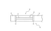
図1は、本発明の一実施の形態に係る触感呈示装置の概略構成を示す側面図であり、図2は、図1の触感呈示装置の概略構成を示す底面図である。触感呈示装置10は、片持ち部材20と、片持ち部材20の一方の面側に配置されたアクチュエータ30とを備える。  FIG. 1 is a side view showing a schematic configuration of a tactile sensation providing apparatus according to an embodiment of the present invention, and FIG. 2 is a bottom view showing a schematic configuration of the tactile sensation providing apparatus of FIG. The tactilesensation providing apparatus 10 includes acantilever member 20 and anactuator 30 disposed on one surface side of thecantilever member 20.

片持ち部材20は、一端が開放端21、他方が固定端22として、可撓性材料により構成される。片持ち部材20は、一方の面(裏面)側に、片持ち部材20の延在方向に離間してアクチュエータ30を保持する一対の保持部23を有する。  Thecantilever member 20 is made of a flexible material with one end as anopen end 21 and the other as a fixedend 22. Thecantilever member 20 has a pair ofholding portions 23 that hold theactuator 30 while being spaced apart from each other in the extending direction of thecantilever member 20 on one surface (back surface) side.

図1及び図2に示すように、一対の保持部23は、下端側においてアクチュエータ30を挟み込むようにして保持(挟持)する。保持部23とアクチュエータ30とは、例えば接着剤により接着される。  As shown in FIGS. 1 and 2, the pair of holdingportions 23 hold (hold) theactuator 30 so as to sandwich theactuator 30 on the lower end side. Theholding part 23 and theactuator 30 are bonded by, for example, an adhesive.

アクチュエータ30は、伸縮変位を行うことにより、片持ち部材20を揺動変位させるための駆動源を構成するもので、例えば圧電素子31を用いて構成される。圧電素子31は、電気信号(電圧)を印加することで、構成材料の電気機械結合係数に従い伸縮又は屈曲変位する素子である。これらの素子は、例えばセラミックや水晶からなるものが用いられる。圧電素子31は、ユニモルフ、バイモルフ又は積層型圧電素子であってよい。積層型圧電素子には、バイモルフを積層した積層型バイモルフ素子や、例えばPZT(チタン酸ジルコン酸鉛)からなる複数の誘電体層と、該複数の誘電体層間に配置された電極層との積層構造体から構成されるスタックタイプのものがある。ユニモルフは電気信号が印加されると伸縮変位し、バイモルフは電気信号が印加されると屈曲変位し、スタックタイプの積層型圧電素子は電気信号が印加されると積層方向に沿って伸縮変位する。本実施の形態では、圧電素子31がスタックタイプの積層型圧電素子からなり、図1において、左右方向に伸縮変位する。圧電素子31の伸縮変位は、触感呈示装置10の制御部により制御される。  Theactuator 30 constitutes a drive source for oscillating and displacing thecantilever member 20 by performing expansion and contraction displacement, and is configured using, for example, apiezoelectric element 31. Thepiezoelectric element 31 is an element that expands and contracts or bends according to an electromechanical coupling coefficient of a constituent material by applying an electric signal (voltage). These elements are made of, for example, ceramic or quartz. Thepiezoelectric element 31 may be a unimorph, bimorph, or multilayer piezoelectric element. The laminated piezoelectric element includes a laminated bimorph element in which bimorphs are laminated, or a laminate of a plurality of dielectric layers made of PZT (lead zirconate titanate), for example, and an electrode layer disposed between the plurality of dielectric layers. There is a stack type composed of structures. The unimorph is elastically displaced when an electric signal is applied, the bimorph is bent and displaced when an electric signal is applied, and the stack type laminated piezoelectric element is elastically displaced along the laminating direction when an electric signal is applied. In the present embodiment, thepiezoelectric element 31 is formed of a stack type stacked piezoelectric element, and is expanded and contracted in the left-right direction in FIG. The expansion / contraction displacement of thepiezoelectric element 31 is controlled by the control unit of the tactilesensation providing apparatus 10.

アクチュエータ30が伸縮変位を行うと、片持ち部材20は、固定端22を支点にして、図1において矢印で示すように開放端21を上下に揺動変位する。  When theactuator 30 is expanded and contracted, thecantilever member 20 swings and displaces theopen end 21 up and down as indicated by arrows in FIG. 1 with the fixedend 22 as a fulcrum.

図3を参照して、圧電素子31の変位による片持ち部材20の動作について説明する。図3は、圧電素子31の伸長変位による片持ち部材20の動作を説明するための模式図である。図3において、圧電素子31の伸長変位前の触感呈示装置10の状態が実線で、圧電素子31の伸長変位後の状態が二点鎖線でそれぞれ示されている。圧電素子31が、実線で示される伸長前の状態から、二点鎖線で示される伸長後の状態に変位した場合、片持ち部材20は、固定端22を支点にして、開放端21が片持ち部材20の表面側(図3の上方向)に変位する。かかる変位により、触感呈示装置10は、片持ち部材20に接触する操作者に、触感を呈示できる。  The operation of thecantilever member 20 due to the displacement of thepiezoelectric element 31 will be described with reference to FIG. FIG. 3 is a schematic diagram for explaining the operation of thecantilever member 20 due to the extension displacement of thepiezoelectric element 31. In FIG. 3, the state of the tactilesensation providing device 10 before thepiezoelectric element 31 is extended and displaced is indicated by a solid line, and the state after thepiezoelectric element 31 is extended and displaced is indicated by a two-dot chain line. When thepiezoelectric element 31 is displaced from the state before extension indicated by a solid line to the state after extension indicated by a two-dot chain line, thecantilever member 20 has the fixedend 22 as a fulcrum and theopen end 21 is cantilevered. Themember 20 is displaced to the surface side (upward direction in FIG. 3). By such displacement, the tactilesensation providing apparatus 10 can present a tactile sensation to an operator who contacts thecantilever member 20.

圧電素子31が伸長するように変位すると、片持ち部材20は、固定端22を支点にして、開放端21が片持ち部材20の表面側(図3の上方向)に変位し、湾曲した状態となる。図3に示すように、2つの保持部23のそれぞれに沿って延長した線(図3の2つの点線)の交点をOとすると、片持ち部材20の湾曲の形状は、点Oを中心とした円弧状に近似できる。保持部23に沿って延長した点線のうち、固定端22側の保持部23に沿って延長した線を線A、開放端21側の保持部23に沿って延長した線を線Bとする。  When thepiezoelectric element 31 is displaced so as to extend, thecantilever member 20 is bent with the fixedend 22 as a fulcrum and theopen end 21 is displaced to the surface side of the cantilever member 20 (upward in FIG. 3). It becomes. As shown in FIG. 3, when the intersection of the lines (two dotted lines in FIG. 3) extending along each of the twoholding portions 23 is O, the curved shape of thecantilever member 20 is centered on the point O. It can be approximated to a circular arc shape. Of the dotted lines extending along theholding portion 23, a line extending along theholding portion 23 on the fixedend 22 side is defined as a line A, and a line extending along theholding portion 23 on theopen end 21 side is defined as a line B.

ここで、説明の便宜上、圧電素子31、片持ち部材20及び保持部23の厚さを無視すると、図3において、変位後の片持ち部材20を示す仮想的な線(図3の一点鎖線)を線C、2つの点線A及びBがなす角をθ、保持部23の長さをdとする。また、伸長前の圧電素子31の長さをL、伸長後の圧電素子31の長さをL´とする。線Bと線Cとの交点を点Pとして、点Oと点Pとの距離をrとする。また、点Pにおける圧電素子31の伸長変位による上方向への変位量をxとし、本実施の形態において、圧電素子31の伸長量ΔLに対する点Pの変位量xを変位拡大率Gと定義する。  Here, for convenience of explanation, ignoring the thicknesses of thepiezoelectric element 31, thecantilever member 20, and theholding portion 23, in FIG. 3, a virtual line indicating thecantilever member 20 after displacement (the dashed line in FIG. 3). Is the line C, the angle formed by the two dotted lines A and B is θ, and the length of theholding portion 23 is d. Further, the length of thepiezoelectric element 31 before expansion is L, and the length of thepiezoelectric element 31 after expansion is L ′. Let the intersection of line B and line C be point P, and let the distance between point O and point P be r. Further, the upward displacement amount due to the expansion displacement of thepiezoelectric element 31 at the point P is x, and in this embodiment, the displacement amount x at the point P with respect to the expansion amount ΔL of thepiezoelectric element 31 is defined as the displacement magnification rate G. .

θが十分小さいとき、線Cと線A及び線Bとの交点間の距離は、伸長前の圧電素子31の長さLに近似できるため、L/r=L´/(r+d)が成立する。従って、圧電素子31の伸長量ΔLは、次式(1)のように表される。
ΔL=L´−L=Ld/r ・・・(1)
When θ is sufficiently small, the distance between the intersections of the line C, the line A, and the line B can be approximated to the length L of thepiezoelectric element 31 before expansion, and therefore L / r = L ′ / (r + d) is established. . Accordingly, the extension amount ΔL of thepiezoelectric element 31 is expressed as the following equation (1).
ΔL = L′−L = Ld / r (1)

また、L/2=r×sin(θ/2)と表されるため、点Pの変位量xは次式(2)により表される。
x=L×sin(θ/2)=L×L/(2r) ・・・(2)
Further, since L / 2 = r × sin (θ / 2), the displacement amount x of the point P is expressed by the following equation (2).
x = L × sin (θ / 2) = L × L / (2r) (2)

変位拡大率Gの定義により、G=x/ΔLであるから、式(1)及び式(2)により、変位拡大率Gは、次式(3)により表される
G=x/ΔL=Ld/ΔL ・・・(3)
Since G = x / ΔL by the definition of the displacement magnification rate G, the displacement magnification rate G is expressed by the following equation (3) according to the equations (1) and (2): G = x / ΔL = Ld / ΔL (3)

式(3)より、圧電素子31の伸長量ΔLが一定に制御される場合、変位拡大率Gは保持部23の長さdの値によって定まる。すなわち、触感呈示装置10において、保持部23の長さdを適宜設計することにより、操作者に良好な触感を呈示するように変位拡大率Gを調整できる。  From Expression (3), when the extension amount ΔL of thepiezoelectric element 31 is controlled to be constant, the displacement magnification rate G is determined by the value of the length d of the holdingportion 23. That is, in the tactilesensation providing apparatus 10, by appropriately designing the length d of the holdingportion 23, the displacement magnification rate G can be adjusted so as to present a good tactile sensation to the operator.

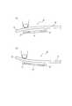
圧電素子31が伸長変位し、触感を提示する場合について、図3を参照して説明したが、圧電素子31は、操作者による片持ち部材20への押圧を検出する押圧検出部としても機能する。図4(a)に示すように、操作者が、片持ち部材20の表面に対して押圧を行うと、片持ち部材20は、固定端22を支点にして、開放端21が下方向に押し下げられる。このとき、圧電素子31は、保持部23により圧縮されるように変位する。  The case where thepiezoelectric element 31 expands and displaces and presents a tactile sensation has been described with reference to FIG. 3, but thepiezoelectric element 31 also functions as a pressure detection unit that detects a pressure applied to thecantilever member 20 by the operator. . As shown in FIG. 4A, when the operator presses against the surface of thecantilever member 20, theopen end 21 is pushed downward with thefixed end 22 as a fulcrum. It is done. At this time, thepiezoelectric element 31 is displaced so as to be compressed by the holdingportion 23.

圧電素子31は、保持部23からの押圧に係る荷重(力)の大きさ(または、荷重(力)の大きさが変化する速さ(加速度))に応じた、電気的な特性である電圧の大きさ(電圧値(以下、押圧に基づくデータと称する))の出力を行う。圧電素子31から出力された押圧に基づくデータは、触感呈示装置10の制御部に送信され、当該データに対応する押圧(入力)がされたことが検出される。このように、圧電素子31は、触感呈示とともに押圧検出にも用いることができる。  Thepiezoelectric element 31 is a voltage having electrical characteristics corresponding to the magnitude of the load (force) applied to the pressing from the holding portion 23 (or the speed (acceleration) at which the magnitude of the load (force) changes). (Voltage value (hereinafter referred to as data based on pressing)) is output. Data based on the pressure output from thepiezoelectric element 31 is transmitted to the control unit of the tactilesensation providing apparatus 10, and it is detected that a pressure (input) corresponding to the data is made. Thus, thepiezoelectric element 31 can be used for pressing detection as well as tactile sensation presentation.

制御部は、圧電素子31の出力(押圧に基づくデータ)に基づいて片持ち部材20への押下荷重が所定値に達したことを検出すると、圧電素子31を伸長変位させるように制御する。すると、図4(b)に示すように、片持ち部材20は、固定端22を支点にして開放端21が上方向に変位するように、湾曲する。これにより、触感呈示装置10は操作者に触感を呈示する。  When detecting that the pressing load on thecantilever member 20 has reached a predetermined value based on the output (data based on the pressure) of thepiezoelectric element 31, the control unit controls thepiezoelectric element 31 to expand and displace. Then, as shown in FIG. 4B, thecantilever member 20 is curved so that theopen end 21 is displaced upward with thefixed end 22 as a fulcrum. Thereby, the tactilesensation providing apparatus 10 presents a tactile sensation to the operator.

図5は、図1の触感呈示装置10の要部の回路構成を示す機能ブロック図である。触感呈示装置10は、制御部40と、記憶部41と、圧電素子駆動部42と、上述した圧電素子31とを有する。  FIG. 5 is a functional block diagram showing a circuit configuration of a main part of the tactilesensation providing apparatus 10 of FIG. The tactilesensation providing apparatus 10 includes acontrol unit 40, a storage unit 41, a piezoelectricelement driving unit 42, and thepiezoelectric element 31 described above.

制御部40は、触感呈示装置10の各機能ブロックを含む装置全体を制御及び管理するプロセッサである。制御部40は、制御手順を規定したプログラムを実行するCPU(Central Processing Unit)等のプロセッサで構成される。かかるプログラムは、例えば記憶部41又は外部の記憶媒体等に格納される。  Thecontrol unit 40 is a processor that controls and manages the entire apparatus including the functional blocks of the tactilesensation providing apparatus 10. Thecontrol unit 40 includes a processor such as a CPU (Central Processing Unit) that executes a program that defines a control procedure. Such a program is stored, for example, in the storage unit 41 or an external storage medium.

記憶部41は、半導体メモリ等で構成され、各種情報や触感呈示装置10を動作させるためのプログラム等を記憶するとともに、ワークメモリとしても機能する。  The storage unit 41 is configured by a semiconductor memory or the like, and stores various information and programs for operating the tactilesensation providing apparatus 10 and also functions as a work memory.

圧電素子駆動部42は、制御部40からの制御信号に基づいて圧電素子31に印加する電気信号を生成して圧電素子31に印加する。  The piezoelectricelement driving unit 42 generates an electrical signal to be applied to thepiezoelectric element 31 based on a control signal from thecontrol unit 40 and applies the electrical signal to thepiezoelectric element 31.

制御部40は、圧電素子31の出力(押圧に基づくデータ)に基づいて片持ち部材20への押下荷重が所定値に達したことを検出すると、圧電素子駆動部42により圧電素子31を所定の駆動パターンで駆動する。圧電素子31の駆動により、片持ち部材20が変位して、操作者に入力に対する触感が呈示される。  When thecontrol unit 40 detects that the pressing load on thecantilever member 20 has reached a predetermined value based on the output of the piezoelectric element 31 (data based on the pressure), the piezoelectricelement driving unit 42 causes thepiezoelectric element 31 to move to a predetermined value. Drive with drive pattern. By driving thepiezoelectric element 31, thecantilever member 20 is displaced, and a tactile sensation with respect to the input is presented to the operator.

圧電素子31の駆動パターンは、記憶部41に記憶しておくことができる。例えば、押しボタンを押した触感を呈示する場合は、所定周波数の半サイクルのパルス状の駆動電圧を圧電素子31に印加して、片持ち部材20を一往復変位させる駆動パターンとすることができる。その他、所定周波数の複数サイクルの駆動電圧を圧電素子31に印加して、片持ち部材20を複数往復変位させる駆動パターンとすることもできる。  The drive pattern of thepiezoelectric element 31 can be stored in the storage unit 41. For example, when presenting a tactile sensation when a push button is pressed, a driving pattern in which thecantilever member 20 is reciprocally displaced by applying a pulse-like driving voltage of a half cycle of a predetermined frequency to thepiezoelectric element 31 can be obtained. . In addition, a driving pattern in which a plurality of cycles of drive voltages having a predetermined frequency are applied to thepiezoelectric element 31 and thecantilever member 20 is displaced a plurality of times can be used.

本実施の形態に係る触感呈示装置10は、片持ち部材20の裏面に設けた保持部23により、アクチュエータ30を保持する。アクチュエータ30が伸縮変位を行うと、伸縮変位が片持ち部材20における上下方向の変位に変換され、操作者に触感が呈示される。このとき、変位を変換する場合における変位拡大率Gは、保持部23の長さdにより決定される。そのため、長さdを調整することにより、良好な触感を呈示しやすくなる。また、触感呈示装置10は、従来の触感呈示装置と比較して、簡単な構造で構成することができる。そのため、従来の触感呈示装置と比較して触感呈示装置10の小型化が実現しやすい。触感呈示装置10は、このような特徴を有するため、多様な機器に実装しやすくなる。以下、本実施の形態に係る触感呈示装置10の実装例について説明する。  The tactilesensation providing apparatus 10 according to the present embodiment holds theactuator 30 by the holdingunit 23 provided on the back surface of thecantilever member 20. When theactuator 30 performs expansion / contraction displacement, the expansion / contraction displacement is converted into a vertical displacement in thecantilever member 20, and a tactile sensation is presented to the operator. At this time, the displacement magnification rate G in the case of converting the displacement is determined by the length d of the holdingunit 23. Therefore, it becomes easy to present a good tactile sensation by adjusting the length d. Further, the tactilesensation providing apparatus 10 can be configured with a simple structure as compared with the conventional tactile sensation providing apparatus. Therefore, compared with the conventional tactile sensation providing apparatus, the tactilesensation providing apparatus 10 can be easily downsized. Since the tactilesensation providing apparatus 10 has such a feature, it can be easily mounted on various devices. Hereinafter, an implementation example of the tactilesensation providing apparatus 10 according to the present embodiment will be described.

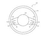
図6は、触感呈示装置10を車両のステアリングホイールに実装した例を示す図である。ステアリングホイール110は、ドライバの手によって握られるリム部111、リム部111の中央に配置され、図示しないステアリングシャフトに接続されてエアバッグ装置及びホーンスイッチ等を収納するボス部112、及び、リム部111とボス部112とを連結する複数のスポーク部113を備える。図6に示したステアリングホイール110は、ボス部112から左右それぞれの方向に延びる2つのスポーク部113を備える。  FIG. 6 is a diagram illustrating an example in which the tactilesensation providing apparatus 10 is mounted on a steering wheel of a vehicle. Thesteering wheel 110 is arranged at the center of therim portion 111, which is gripped by the driver's hand, and is connected to a steering shaft (not shown) to store an airbag device and a horn switch. 111 and aboss 112 are provided with a plurality ofspokes 113. Thesteering wheel 110 shown in FIG. 6 includes two spokeportions 113 extending from theboss portion 112 in the left and right directions.

ステアリングホイール110は、2つのスポーク部113のそれぞれに触感呈示装置10を備える。スポーク部113は、ステアリングホイール110の中央部から周縁のリム部111に向かうU字型の切れ込み114を有する。切れ込み114の位置は、図6に示したものに限られないが、切れ込み114により形成されたU字部材115が、操作者であるドライバがリム部111を握って車両を運転する場合に、ドライバの指が接触可能な位置に設けられることが好ましい。また、U字型の切れ込み114は、リム部111からボス部112に向かう方向に設けられていてもよい。  Thesteering wheel 110 includes the tactilesensation providing device 10 in each of the two spokeportions 113. Thespoke portion 113 has aU-shaped cut 114 extending from the center portion of thesteering wheel 110 toward theperipheral rim portion 111. The position of thenotch 114 is not limited to that shown in FIG. It is preferable that the finger is provided at a position where it can be touched. TheU-shaped cut 114 may be provided in a direction from therim portion 111 toward theboss portion 112.

U字部材115は、触感呈示装置10の片持ち部材20として機能する。U字部材115の先端側(リム部111側)は、図1における開放端21に相当し、ボス部112側は、図1における固定端22に相当する。U字部材115の裏側には、保持部23があり、保持部23により圧電素子31が保持される。  TheU-shaped member 115 functions as thecantilever member 20 of the tactilesensation providing apparatus 10. The front end side (rim portion 111 side) of theU-shaped member 115 corresponds to theopen end 21 in FIG. 1, and theboss portion 112 side corresponds to thefixed end 22 in FIG. On the back side of theU-shaped member 115, there is a holdingportion 23, and thepiezoelectric element 31 is held by the holdingportion 23.

ドライバは、ステアリング操作により車両の操舵操作を行うことができるとともに、U字部材115への押圧操作を行うことにより押圧操作に対応する車両の被制御装置の操作を行うことができる。すなわち、ドライバがU字部材115に押圧操作を行うと、U字部材115の裏側に配置された圧電素子31が、図4で説明したように圧縮される。そして、制御部40は、圧電素子31の出力(押圧に基づくデータ)に基づいてU字部材115への押下荷重が所定値に達したことを検出すると、押圧操作に対応する車両の被制御装置に対して所定の操作を行う。所定の操作は、例えば車両の被制御装置が実行可能な機能の1つの選択等であるが、これに限られない。  The driver can perform the steering operation of the vehicle by the steering operation, and can operate the controlled device of the vehicle corresponding to the pressing operation by performing the pressing operation to theU-shaped member 115. That is, when the driver performs a pressing operation on theU-shaped member 115, thepiezoelectric element 31 disposed on the back side of theU-shaped member 115 is compressed as described with reference to FIG. And if thecontrol part 40 detects that the pressing load to theU-shaped member 115 reached predetermined value based on the output (data based on press) of thepiezoelectric element 31, the controlled apparatus of the vehicle corresponding to press operation will be demonstrated. A predetermined operation is performed. The predetermined operation is, for example, selection of one of functions executable by the controlled device of the vehicle, but is not limited thereto.

また、制御部40は、圧電素子31の出力(押圧に基づくデータ)に基づいてU字部材115への押下荷重が所定値に達したことを検出すると、圧電素子31を伸長変位させるように制御する。かかる制御によりU字部材115が変位し、ステアリングホイール110はドライバに触感を提示できる。ドライバは、U字部材115の変位(振動)により、目視確認によらず、押圧操作が入力されたことを確認できる。そのため、運転時におけるドライバの視線の移動を防止しやすくなり、運転中における操作の安全性を確保しやすくなる。  Further, when thecontrol unit 40 detects that the pressing load on theU-shaped member 115 has reached a predetermined value based on the output (data based on the pressure) of thepiezoelectric element 31, thecontrol unit 40 controls thepiezoelectric element 31 to expand and displace. To do. By such control, theU-shaped member 115 is displaced, and thesteering wheel 110 can present a tactile sensation to the driver. The driver can confirm that the pressing operation is input by the displacement (vibration) of theU-shaped member 115 regardless of visual confirmation. Therefore, it becomes easy to prevent movement of the driver's line of sight during driving, and it becomes easy to ensure operation safety during driving.

触感呈示装置10は、多様な電子機器に実装することができる。触感呈示装置10を実装しうる電子機器には、例えば、スマートフォン等の携帯電話機、携帯型ミュージックプレイヤ、ノートパソコン、腕時計、タブレット端末、ゲーム機、コンピュータ操作用マウス等が含まれるが、これらに限られない。これらの電子機器のうち、触感呈示装置10を実装するコンピュータ操作用マウス及び携帯電話機の例について、具体的に説明する。  The tactilesensation providing apparatus 10 can be mounted on various electronic devices. Examples of electronic devices on which the tactilesensation providing apparatus 10 can be mounted include a mobile phone such as a smartphone, a portable music player, a notebook computer, a wristwatch, a tablet terminal, a game machine, and a mouse for computer operation. I can't. Among these electronic devices, an example of a computer operating mouse and a mobile phone on which the tactilesensation providing apparatus 10 is mounted will be specifically described.

図7は、触感呈示装置10を実装したコンピュータ操作用マウスを示す図である。マウス120は有線又は無線によりコンピュータに接続され、操作者はマウス120を操作することにより、マウス120に接続されたコンピュータに対して各種操作を行う。  FIG. 7 is a diagram illustrating a computer operating mouse on which the tactilesensation providing apparatus 10 is mounted. Themouse 120 is connected to the computer by wire or wirelessly, and the operator operates themouse 120 to perform various operations on the computer connected to themouse 120.

図7のマウス120は、操作者が右手で操作を行う場合、手のひらで覆うように保持するマウス本体121と、通常人差し指で入力操作を行う左ボタン122と、通常中指で入力操作を行う右ボタン123とを備える。以下説明するマウス120が備える触感呈示装置10に関する機構を除き、マウス120は、従来周知のマウスと同様の構造及び機能を有する。操作者がマウス120を通常の使用態様で保持した場合に指先が配置される側をマウス120の前方、手首が配置される側をマウス120の後方として、以下説明する。  Themouse 120 in FIG. 7 includes amouse body 121 that is held so as to be covered with a palm when the operator performs an operation with the right hand, aleft button 122 that performs an input operation with a normal index finger, and a right button that performs an input operation with a normal middle finger. 123. Except for the mechanism related to the tactilesensation providing apparatus 10 included in themouse 120 described below, themouse 120 has the same structure and function as a conventionally known mouse. In the following description, the side on which the fingertip is placed when the operator holds themouse 120 in a normal usage mode is the front of themouse 120 and the side on which the wrist is placed is the back of themouse 120.

マウス120において、左ボタン122及び右ボタン123それぞれの前方側は、上下に変位可能に構成され、マウス本体121への接続部分である後方側は、マウス本体121に対して変位しないように構成されている。すなわち、左ボタン122及び右ボタン123それぞれの前方側は図1における開放端21に相当し、後方側は図1における固定端22に相当する。左ボタン122及び右ボタン123は、裏面側すなわちマウス120の内部側に、それぞれ保持部23を備える。保持部23は、マウス120の前後の方向に伸縮変位可能に圧電素子31を保持している。左ボタン122及び右ボタン123は、それぞれ図1の片持ち部材20に相当する。  In themouse 120, the front side of each of theleft button 122 and theright button 123 is configured to be vertically movable, and the rear side, which is a connection portion to the mousemain body 121, is configured not to be displaced with respect to the mousemain body 121. ing. That is, the front side of each of theleft button 122 and theright button 123 corresponds to theopen end 21 in FIG. 1, and the rear side corresponds to thefixed end 22 in FIG. Each of theleft button 122 and theright button 123 includes a holdingunit 23 on the back side, that is, on the inner side of themouse 120. The holdingpart 23 holds thepiezoelectric element 31 so that it can be expanded and contracted in the front-rear direction of themouse 120. Theleft button 122 and theright button 123 correspond to thecantilever member 20 of FIG.

操作者が人差し指で左ボタン122を押下(クリック)すると、左ボタン122の裏側に配置された圧電素子31が、図4で説明したように圧縮される。そして、制御部40は、圧電素子31の出力(押圧に基づくデータ)に基づいて左ボタン122への押下荷重が所定値に達したことを検出すると、マウス120が接続されたコンピュータに対して、押圧操作に対応する所定の操作を行うように指示する信号を送信する。  When the operator presses (clicks) theleft button 122 with the index finger, thepiezoelectric element 31 disposed on the back side of theleft button 122 is compressed as described with reference to FIG. And if thecontrol part 40 detects that the pressing load to theleft button 122 reached predetermined value based on the output (data based on press) of thepiezoelectric element 31, with respect to the computer to which themouse 120 was connected, A signal instructing to perform a predetermined operation corresponding to the pressing operation is transmitted.

また、制御部40は、圧電素子31の出力(押圧に基づくデータ)に基づいて左ボタン122への押下荷重が所定値に達したことを検出すると、圧電素子31を伸長変位させるように制御する。かかる制御により左ボタン122が変位し、マウス120は操作者に触感を提示できる。このとき、制御部40は、操作者が実際のボタンをクリックしたような触感(クリック触感)を得られるように、圧電素子31を制御することが好ましい。  Further, when thecontrol unit 40 detects that the pressing load on theleft button 122 has reached a predetermined value based on the output (data based on the pressure) of thepiezoelectric element 31, thecontrol unit 40 controls thepiezoelectric element 31 to expand and displace. . By such control, theleft button 122 is displaced, and themouse 120 can present a tactile sensation to the operator. At this time, it is preferable that thecontrol unit 40 controls thepiezoelectric element 31 so as to obtain a tactile sensation (click tactile sensation) as if the operator clicked an actual button.

また、操作者が中指で右ボタン123を押下(クリック)した場合においても、制御部40は、上述の左ボタン122の押下時と同様の制御を行うことにより、操作者にクリック触感を呈示できる。  Even when the operator presses (clicks) theright button 123 with the middle finger, thecontrol unit 40 can present the operator with a click tactile sensation by performing the same control as when theleft button 122 is pressed. .

図8は、触感呈示装置10を実装した携帯電話機を示す図である。携帯電話機50は、外観形状が概略長方形状を成す筐体51を備える。筐体51は、上部筐体51aと下部筐体51bとにより構成される。上部筐体51aと下部筐体51bとは、弾性部材で構成される接合部52により接合され、1つの筐体51を構成している。接合部52は、防水性のテープ又はスポンジ等として構成されていてもよい。上部筐体51aと下部筐体51bとは、接合部52を介して、互いに変位可能に接合される。上部筐体51aと下部筐体51bとは、変位方向を筐体51の厚み方向に制限するガイドに沿って変位するものであってもよい。  FIG. 8 is a diagram showing a mobile phone on which the tactilesensation providing apparatus 10 is mounted. Themobile phone 50 includes ahousing 51 whose external shape is substantially rectangular. Thecasing 51 includes anupper casing 51a and alower casing 51b. Theupper housing 51a and thelower housing 51b are joined by a joiningportion 52 made of an elastic member to constitute onehousing 51. Thejoint portion 52 may be configured as a waterproof tape, sponge, or the like. Theupper housing 51a and thelower housing 51b are joined to each other via a joiningportion 52 so as to be displaceable. Theupper casing 51 a and thelower casing 51 b may be displaced along a guide that restricts the displacement direction to the thickness direction of thecasing 51.

筐体51は、金属や硬質プラスチック等で形成される。上部筐体51aには、筐体51の表面53側にパネル54が配置されている。また、筐体51の内部には、パネル54の下側に図1にパネル54の一部を切り欠いて示すように、表示部55が保持されている。筐体51は、内部に触感呈示装置10を備える。  Thecasing 51 is made of metal, hard plastic, or the like. Apanel 54 is disposed on theupper casing 51 a on thesurface 53 side of thecasing 51. In addition, adisplay unit 55 is held inside thehousing 51 as shown in FIG. Thehousing 51 includes the tactilesensation providing device 10 inside.

パネル54は、接触を検出するタッチパネル又は表示部55を保護するカバーパネル等からなる。パネル54は、例えばガラス又はアクリル等の合成樹脂により、例えば長方形状に形成される。パネル54は、タッチパネルである場合、操作者の指、ペン又はスタイラスペン等の接触物による接触を検出する。タッチパネルの検出方式は、静電容量方式、抵抗膜方式、表面弾性波方式(又は超音波方式)、赤外線方式、電磁誘導方式又は荷重検出方式等の任意の方式を用いることができる。ここでは、説明の便宜上、パネル54は、タッチパネルとする。この場合、パネル54は表示部55と一体的に構成される場合もある。パネル54は、パネル表面54aの周辺部を除く領域が、筐体51の表面53に形成された開口53aから露出する。  Thepanel 54 includes a touch panel that detects contact or a cover panel that protects thedisplay unit 55. Thepanel 54 is formed, for example, in a rectangular shape from a synthetic resin such as glass or acrylic. When thepanel 54 is a touch panel, it detects contact with a contact object such as an operator's finger, pen, or stylus pen. As a detection method of the touch panel, an arbitrary method such as a capacitance method, a resistance film method, a surface acoustic wave method (or an ultrasonic method), an infrared method, an electromagnetic induction method, or a load detection method can be used. Here, for convenience of description, thepanel 54 is a touch panel. In this case, thepanel 54 may be configured integrally with thedisplay unit 55. In thepanel 54, a region excluding the peripheral portion of thepanel surface 54 a is exposed from an opening 53 a formed in thesurface 53 of thehousing 51.

表示部55は、例えば、液晶ディスプレイ、有機ELディスプレイ、無機ELディスプレイ、電子ペーパ等を用いて構成される。表示部55は、ブラウザや電子ブック等のアプリケーションソフトウェア(以下、単に「アプリケーション」と記す)における画像(ページ)、アイコンや押しボタン等の入力用オブジェクト等を表示する。  Thedisplay unit 55 is configured using, for example, a liquid crystal display, an organic EL display, an inorganic EL display, electronic paper, or the like. Thedisplay unit 55 displays images (pages), input objects such as icons and push buttons in application software (hereinafter simply referred to as “application”) such as a browser and an electronic book.

図9は、上部筐体51aを取り除いて示す、下部筐体51bにおける触感呈示装置10の配置例を示す平面図である。下部筐体51bには、図9に示すように、下部筐体51bの四隅の周辺に、下部筐体51bの長辺に平行に、4つの触感呈示装置10が配置されている。各触感呈示装置10は、下部筐体51bの中央側において、支持部56により固定端22が固定されている。また、各触感呈示装置10の開放端21には、上部筐体51a側に突起部24が設けられている。触感呈示装置10は、図9に仮想線で示した表示部55の表示領域Dから外れた、下部筐体51bの四隅の近傍で、突起部24とパネル54とが係合するように支持部56により支持される。  FIG. 9 is a plan view illustrating an arrangement example of the tactilesensation providing device 10 in thelower housing 51b, with theupper housing 51a removed. As shown in FIG. 9, four tactilesensation providing devices 10 are arranged in thelower casing 51b around the four corners of thelower casing 51b in parallel with the long sides of thelower casing 51b. Each tactilesensation providing device 10 has a fixedend 22 fixed by asupport portion 56 on the center side of thelower housing 51b. In addition, aprotrusion 24 is provided on theopen end 21 of each tactilesensation providing device 10 on theupper housing 51a side. The tactilesensation providing apparatus 10 has a support portion so that theprotrusion 24 and thepanel 54 engage with each other in the vicinity of the four corners of thelower housing 51b, which is out of the display area D of thedisplay portion 55 indicated by a virtual line in FIG. 56.

図10は、携帯電話機50の要部の概略構成を示す断面図であり、携帯電話機50の筐体51の長辺に平行な断面を示す図である。図10に示すように、触感呈示装置10は、支持部56により支持され、突起部24においてパネル54に係合する。  FIG. 10 is a cross-sectional view showing a schematic configuration of a main part of themobile phone 50, and shows a cross section parallel to the long side of thecasing 51 of themobile phone 50. As shown in FIG. 10, the tactilesensation providing apparatus 10 is supported by thesupport portion 56 and engages with thepanel 54 at the protrudingportion 24.

図11は、携帯電話機50の動作の一例を説明する模式図である。例えば、携帯電話機50の操作者が、図11(a)に示すようにパネル54を押圧すると、パネル54は、接合部52の弾性力に抗して、上部筐体51aと一体となった状態で、筐体51の内部方向(図11(a)では下方向)に押し下げられる。すると、パネル54に係合する突起部24が押し下げられ、突起部24が設けられた開放端21が押し下げられる。固定端22は、支持部56により支持されているため、片持ち部材20は湾曲し、圧電素子31は保持部23により圧縮されるように変位する。  FIG. 11 is a schematic diagram for explaining an example of the operation of themobile phone 50. For example, when the operator of themobile phone 50 presses thepanel 54 as shown in FIG. 11A, thepanel 54 is integrated with theupper casing 51 a against the elastic force of thejoint portion 52. Thus, it is pushed down in the inner direction of the casing 51 (downward in FIG. 11A). Then, theprojection 24 that engages with thepanel 54 is pushed down, and theopen end 21 provided with theprojection 24 is pushed down. Since thefixed end 22 is supported by thesupport portion 56, thecantilever member 20 is curved, and thepiezoelectric element 31 is displaced so as to be compressed by the holdingportion 23.

制御部は、圧電素子31の出力(押圧に基づくデータ)に基づいて片持ち部材20への押下荷重が所定値に達したことを検出すると、圧電素子31を伸長変位させるように制御する。すると、図11(b)に示すように、片持ち部材20は、固定端22を支点にして開放端21が上方向に変位するように、湾曲する。これにより、突起部24が押し上げられ、突起部24に係合するパネル54が、上部筐体51aと一体となった状態で押し上げられる。携帯電話機50は、パネル54のかかる変位により操作者に触感を呈示する。  When detecting that the pressing load on thecantilever member 20 has reached a predetermined value based on the output (data based on the pressure) of thepiezoelectric element 31, the control unit controls thepiezoelectric element 31 to expand and displace. Then, as shown in FIG. 11B, thecantilever member 20 is curved so that theopen end 21 is displaced upward with thefixed end 22 as a fulcrum. Thereby, theprotrusion 24 is pushed up, and thepanel 54 engaged with theprotrusion 24 is pushed up in a state of being integrated with theupper casing 51a. Thecellular phone 50 presents a tactile sensation to the operator due to the displacement of thepanel 54.

なお、本発明は、上記実施の形態にのみ限定されるものではなく、幾多の変形又は変更が可能である。例えば、触感呈示装置10は、片持ち部材20の裏面側に、片持ち部材20の延在方向に交差して延在する溝を有していてもよい。例えば図12(a)に示すように、溝25は片持ち部材20の一部に切り込みとして構成されていてもよい。また、例えば図12(b)に示すように、溝25は、片持ち部材20における一対の保持部23の間において、片持ち部材20の厚みを変化させることにより構成されていてもよい。片持ち部材20に溝25を設けることにより、片持ち部材20が上下方向に変位しやすくなる。また、溝25の位置及び形状を調整することにより、圧電素子31が伸縮変位した場合における片持ち部材20の変位の大きさ等を調整できる。  In addition, this invention is not limited only to the said embodiment, Many deformation | transformation or a change is possible. For example, the tactilesensation providing apparatus 10 may have a groove extending on the back surface side of thecantilever member 20 so as to intersect with the extending direction of thecantilever member 20. For example, as illustrated in FIG. 12A, thegroove 25 may be configured as a cut in a part of thecantilever member 20. For example, as illustrated in FIG. 12B, thegroove 25 may be configured by changing the thickness of thecantilever member 20 between the pair of holdingportions 23 in thecantilever member 20. By providing thegroove 25 in thecantilever member 20, thecantilever member 20 is easily displaced in the vertical direction. In addition, by adjusting the position and shape of thegroove 25, the magnitude of the displacement of thecantilever member 20 when thepiezoelectric element 31 is expanded and contracted can be adjusted.

また、触感呈示装置10は、表面側の一部又は全体にタッチパッドを備えていてもよい。図13は、表面側の一部にタッチパッドを備える触感呈示装置10を示す図であり、触感呈示装置10を表面側から見た場合の図である。図13の例において、タッチパッド60は開放端21側に配置されているが、タッチパッド60の位置はこれに限られず、例えば、片持ち部材20全体にわたって配置されていてもよい。タッチパッド60は、操作者によるタッチパッド60への接触位置をタッチ面において検出する。  Further, the tactilesensation providing apparatus 10 may include a touch pad on a part or the whole of the surface side. FIG. 13 is a diagram illustrating the tactilesensation providing apparatus 10 including a touch pad on a part of the surface side, and is a diagram when the tactilesensation providing apparatus 10 is viewed from the front side. In the example of FIG. 13, thetouch pad 60 is disposed on theopen end 21 side, but the position of thetouch pad 60 is not limited to this, and may be disposed over theentire cantilever member 20, for example. Thetouch pad 60 detects the contact position of the operator with thetouch pad 60 on the touch surface.

操作者が触感呈示装置10を押圧すると、片持ち部材20が変位することにより、圧電素子31が圧縮されるように変位する。圧電素子31は、押圧に基づくデータを制御部に送信する。また、操作者による触感呈示装置10の押圧時に、タッチパッド60は、接触位置を検出する。検出された接触位置に関するデータは制御部に送信される。制御部は、圧電素子31の出力(押圧に基づくデータ)及びタッチパッド60の出力(接触位置に関するデータ)に応じて、圧電素子31の伸縮変位を制御する。  When the operator presses the tactilesensation providing apparatus 10, thecantilever member 20 is displaced, so that thepiezoelectric element 31 is displaced so as to be compressed. Thepiezoelectric element 31 transmits data based on the pressure to the control unit. Further, when the operator presses the tactilesensation providing apparatus 10, thetouch pad 60 detects a contact position. Data regarding the detected contact position is transmitted to the control unit. The control unit controls the expansion / contraction displacement of thepiezoelectric element 31 according to the output of the piezoelectric element 31 (data based on pressing) and the output of the touch pad 60 (data regarding the contact position).

制御部は、例えば、圧電素子31の出力に基づいて片持ち部材20への押下荷重が所定値に達したことを検出し、かつ、タッチパッド60の出力に基づいて所定の位置が接触されていることを検出すると、圧電素子31を伸長変位させるように制御する。制御部は、例えばタッチパッド60における接触位置が所定の位置でない場合、片持ち部材20への押下荷重が所定値に達していても、触感を呈示しなくてもよい。また、制御部は、タッチパッド60における接触位置に応じて、異なるパターンで圧電素子31を伸縮変位させるように制御してもよい。このように、タッチパッド60を備える触感呈示装置10によれば、接触位置に応じた圧電素子31の制御により、触感呈示の方法を多様にできる。  For example, the control unit detects that the pressing load on thecantilever member 20 has reached a predetermined value based on the output of thepiezoelectric element 31, and the predetermined position is touched based on the output of thetouch pad 60. If it is detected, thepiezoelectric element 31 is controlled to be extended and displaced. For example, when the contact position on thetouch pad 60 is not a predetermined position, the control unit may not present a tactile sensation even if the pressing load on thecantilever member 20 reaches a predetermined value. Further, the control unit may perform control so that thepiezoelectric element 31 is expanded and contracted in a different pattern according to the contact position on thetouch pad 60. As described above, according to the tactilesensation providing apparatus 10 including thetouch pad 60, various tactile sensation presentation methods can be performed by controlling thepiezoelectric element 31 according to the contact position.

10 触感呈示装置
20 片持ち部材
21 開放端
22 固定端
23 保持部
24 突起部
25 溝
30 アクチュエータ
31 圧電素子
40 制御部
41 記憶部
42 圧電素子駆動部
50 携帯電話機
51 筐体
51a 上部筐体
51b 下部筐体
52 接合部
53 表面
54 パネル
55 表示部
56 支持部
60 タッチパッド
110 ステアリングホイール
111 リム部
112 ボス部
113 スポーク部
114 切れ込み
115 U字部材
120 マウス
121 マウス本体
122 左ボタン
123 右ボタン
DESCRIPTION OFSYMBOLS 10 Tactilesensation presentation apparatus 20Cantilever member 21Open end 22Fixed end 23Holding part 24Projection part 25Groove 30Actuator 31Piezoelectric element 40 Control part 41 Memory |storage part 42 Piezoelectric element drivepart 50Mobile phone 51 Housing | casing 51a Upper housing |casing 51bLower part Case 52Joint portion 53Surface 54Panel 55Display portion 56Support portion 60Touch pad 110Steering wheel 111Rim portion 112Boss portion 113Spoke portion 114Notch 115U-shaped member 120Mouse 121Mouse body 122Left button 123 Right button

Claims (2)

Translated fromJapanese
一端が固定され、他端が開放された揺動可能な片持ち部材と、
前記片持ち部材の延在方向に沿って伸縮可能に該片持ち部材の一方の面側に配置されたアクチュエータと、を備え、
前記片持ち部材が他方の面側から接触物により押圧されると、該片持ち部材が変位するとともに前記アクチュエータが圧縮され、
前記アクチュエータが伸長すると、前記片持ち部材に前記押圧に反する力を発生させて前記接触物に対して触感を呈示し、
前記片持ち部材は、前記他端側の前記一方の面側に、該片持ち部材の延在方向に交差して延在する溝を有する、触感呈示装置。
A swingable cantilever member having one end fixed and the other end open;
An actuator disposed on one surface side of the cantilever member so as to be expandable and contractible along the extending direction of the cantilever member,
When the cantilever member is pressed by the contact object from the other surface side, the cantilever member is displaced and the actuator is compressed,
When the actuator is extended, the cantilever member generates a force against the pressing and presents a tactile sensation to the contact object,
It said cantilevered member, on the one surface side of the other end has a groove that extends to intersect the extending direction of the該片retentionmember, tactile sensation presentation apparatus.
一端が固定され、他端が開放された揺動可能な片持ち部材と、
前記片持ち部材の延在方向に沿って伸縮可能に該片持ち部材の一方の面側に配置されたアクチュエータと、を備え、
前記片持ち部材が他方の面側から接触物により押圧されると、該片持ち部材が変位するとともに前記アクチュエータが圧縮され、
前記アクチュエータが伸長すると、前記片持ち部材に前記押圧に反する力を発生させて前記接触物に対して触感を呈示し、
前記片持ち部材の前記他方の面側に配置されたタッチパッドを備え、
前記アクチュエータは、前記タッチパッドへの前記接触物の接触位置に応じて伸縮変位される、触感呈示装置。
A swingable cantilever member having one end fixed and the other end open;
An actuator disposed on one surface side of the cantilever member so as to be expandable and contractible along the extending direction of the cantilever member,
When the cantilever member is pressed by the contact object from the other surface side, the cantilever member is displaced and the actuator is compressed,
When the actuator is extended, the cantilever member generates a force against the pressing and presents a tactile sensation to the contact object,
A touch pad disposed on the other surface of the cantilever member;
Said actuator, said being stretched displaced in accordance with the contact position of the touch object on the touchpad, touch sensitive presentation device.
JP2014229422A2014-11-122014-11-12 Tactile presentation deviceActiveJP6199847B2 (en)

Priority Applications (1)

Application NumberPriority DateFiling DateTitle
JP2014229422AJP6199847B2 (en)2014-11-122014-11-12 Tactile presentation device

Applications Claiming Priority (1)

Application NumberPriority DateFiling DateTitle
JP2014229422AJP6199847B2 (en)2014-11-122014-11-12 Tactile presentation device

Related Child Applications (1)

Application NumberTitlePriority DateFiling Date
JP2017143766ADivisionJP6382409B2 (en)2017-07-252017-07-25 Tactile presentation device

Publications (2)

Publication NumberPublication Date
JP2016095550A JP2016095550A (en)2016-05-26
JP6199847B2true JP6199847B2 (en)2017-09-20

Family

ID=56071165

Family Applications (1)

Application NumberTitlePriority DateFiling Date
JP2014229422AActiveJP6199847B2 (en)2014-11-122014-11-12 Tactile presentation device

Country Status (1)

CountryLink
JP (1)JP6199847B2 (en)

Families Citing this family (1)

* Cited by examiner, † Cited by third party
Publication numberPriority datePublication dateAssigneeTitle
JP6504011B2 (en)*2015-10-022019-04-24株式会社村田製作所 Tactile presentation device

Family Cites Families (6)

* Cited by examiner, † Cited by third party
Publication numberPriority datePublication dateAssigneeTitle
JP4869568B2 (en)*2004-06-142012-02-08ソニー株式会社 Input device and electronic device
JP2010157037A (en)*2008-12-262010-07-15Nissha Printing Co LtdPanel member having oscillating element
JP2012073588A (en)*2010-08-312012-04-12Kenta NakamuraPin input/output device realizing input/output unification
JP2013012148A (en)*2011-06-302013-01-17Fujitsu LtdTactile presentation touch panel and electronic equipment using the touch panel
JP2013238941A (en)*2012-05-122013-11-28Kyocera CorpPiezoelectric device, input device, display device, and electronic apparatus
JP6052704B2 (en)*2012-07-102016-12-27カシオ計算機株式会社 INPUT DEVICE, INPUT OPERATION ANALYSIS METHOD, INPUT OPERATION ANALYSIS PROGRAM

Also Published As

Publication numberPublication date
JP2016095550A (en)2016-05-26

Similar Documents

PublicationPublication DateTitle
JP6073451B1 (en) Electronics
JP5704428B2 (en) Touch panel device and control method of touch panel device
CN100430874C (en)Input/output device and electronic device using the same
JP4543863B2 (en) Input/output devices and electronic devices with tactile functions
JP6246640B2 (en) Electronics
WO2005015375A1 (en)Tactile and force feedback device
JP5700086B2 (en) Input device and imaging device
WO2015079688A1 (en)Electronic instrument
JP2017111462A (en) Tactile sensation presentation apparatus and tactile sensation presentation method
WO2016027668A1 (en)Tactile sensation presentation device
WO2013061605A1 (en)Force-feedback device
JP2011175518A (en)Touch panel device
JP2012068823A (en)Display device with input function
JP6528086B2 (en) Electronics
JP6382409B2 (en) Tactile presentation device
JP6199847B2 (en) Tactile presentation device
JP6294170B2 (en) Tactile presentation device
WO2015098061A1 (en)Electronic instrument
JP6490400B2 (en) Tactile presentation device
JP6613153B2 (en) Tactile presentation device
JP2017199200A (en)Touch manipulation device
WO2015079687A1 (en)Electronic device
KR20150079445A (en)Devices, systems, and methods for using corrugated tessellation to create surface features
JP6282575B2 (en) Tactile presentation device
JP2005339298A (en)Input device, and electronic device

Legal Events

DateCodeTitleDescription
A977Report on retrieval

Free format text:JAPANESE INTERMEDIATE CODE: A971007

Effective date:20161128

A131Notification of reasons for refusal

Free format text:JAPANESE INTERMEDIATE CODE: A131

Effective date:20161220

A02Decision of refusal

Free format text:JAPANESE INTERMEDIATE CODE: A02

Effective date:20170425

A521Written amendment

Free format text:JAPANESE INTERMEDIATE CODE: A523

Effective date:20170725

A911Transfer of reconsideration by examiner before appeal (zenchi)

Free format text:JAPANESE INTERMEDIATE CODE: A911

Effective date:20170731

TRDDDecision of grant or rejection written
A01Written decision to grant a patent or to grant a registration (utility model)

Free format text:JAPANESE INTERMEDIATE CODE: A01

Effective date:20170822

A61First payment of annual fees (during grant procedure)

Free format text:JAPANESE INTERMEDIATE CODE: A61

Effective date:20170824

R150Certificate of patent or registration of utility model

Ref document number:6199847

Country of ref document:JP

Free format text:JAPANESE INTERMEDIATE CODE: R150


[8]ページ先頭

©2009-2025 Movatter.jp