JP6199619B2 - Vapor growth equipment - Google Patents
Vapor growth equipmentDownload PDFInfo
- Publication number
- JP6199619B2 JP6199619B2JP2013124847AJP2013124847AJP6199619B2JP 6199619 B2JP6199619 B2JP 6199619B2JP 2013124847 AJP2013124847 AJP 2013124847AJP 2013124847 AJP2013124847 AJP 2013124847AJP 6199619 B2JP6199619 B2JP 6199619B2
- Authority
- JP
- Japan
- Prior art keywords
- gas
- central
- lateral
- reaction chamber
- flow path
- Prior art date
- Legal status (The legal status is an assumption and is not a legal conclusion. Google has not performed a legal analysis and makes no representation as to the accuracy of the status listed.)
- Active
Links
Images


Classifications
- C—CHEMISTRY; METALLURGY
- C23—COATING METALLIC MATERIAL; COATING MATERIAL WITH METALLIC MATERIAL; CHEMICAL SURFACE TREATMENT; DIFFUSION TREATMENT OF METALLIC MATERIAL; COATING BY VACUUM EVAPORATION, BY SPUTTERING, BY ION IMPLANTATION OR BY CHEMICAL VAPOUR DEPOSITION, IN GENERAL; INHIBITING CORROSION OF METALLIC MATERIAL OR INCRUSTATION IN GENERAL
- C23C—COATING METALLIC MATERIAL; COATING MATERIAL WITH METALLIC MATERIAL; SURFACE TREATMENT OF METALLIC MATERIAL BY DIFFUSION INTO THE SURFACE, BY CHEMICAL CONVERSION OR SUBSTITUTION; COATING BY VACUUM EVAPORATION, BY SPUTTERING, BY ION IMPLANTATION OR BY CHEMICAL VAPOUR DEPOSITION, IN GENERAL
- C23C16/00—Chemical coating by decomposition of gaseous compounds, without leaving reaction products of surface material in the coating, i.e. chemical vapour deposition [CVD] processes
- C23C16/44—Chemical coating by decomposition of gaseous compounds, without leaving reaction products of surface material in the coating, i.e. chemical vapour deposition [CVD] processes characterised by the method of coating
- C23C16/455—Chemical coating by decomposition of gaseous compounds, without leaving reaction products of surface material in the coating, i.e. chemical vapour deposition [CVD] processes characterised by the method of coating characterised by the method used for introducing gases into reaction chamber or for modifying gas flows in reaction chamber
- C23C16/45563—Gas nozzles
- C23C16/45574—Nozzles for more than one gas
- C—CHEMISTRY; METALLURGY
- C23—COATING METALLIC MATERIAL; COATING MATERIAL WITH METALLIC MATERIAL; CHEMICAL SURFACE TREATMENT; DIFFUSION TREATMENT OF METALLIC MATERIAL; COATING BY VACUUM EVAPORATION, BY SPUTTERING, BY ION IMPLANTATION OR BY CHEMICAL VAPOUR DEPOSITION, IN GENERAL; INHIBITING CORROSION OF METALLIC MATERIAL OR INCRUSTATION IN GENERAL
- C23C—COATING METALLIC MATERIAL; COATING MATERIAL WITH METALLIC MATERIAL; SURFACE TREATMENT OF METALLIC MATERIAL BY DIFFUSION INTO THE SURFACE, BY CHEMICAL CONVERSION OR SUBSTITUTION; COATING BY VACUUM EVAPORATION, BY SPUTTERING, BY ION IMPLANTATION OR BY CHEMICAL VAPOUR DEPOSITION, IN GENERAL
- C23C16/00—Chemical coating by decomposition of gaseous compounds, without leaving reaction products of surface material in the coating, i.e. chemical vapour deposition [CVD] processes
- C23C16/44—Chemical coating by decomposition of gaseous compounds, without leaving reaction products of surface material in the coating, i.e. chemical vapour deposition [CVD] processes characterised by the method of coating
- C23C16/455—Chemical coating by decomposition of gaseous compounds, without leaving reaction products of surface material in the coating, i.e. chemical vapour deposition [CVD] processes characterised by the method of coating characterised by the method used for introducing gases into reaction chamber or for modifying gas flows in reaction chamber
- C23C16/45563—Gas nozzles
- C23C16/45565—Shower nozzles
- C—CHEMISTRY; METALLURGY
- C23—COATING METALLIC MATERIAL; COATING MATERIAL WITH METALLIC MATERIAL; CHEMICAL SURFACE TREATMENT; DIFFUSION TREATMENT OF METALLIC MATERIAL; COATING BY VACUUM EVAPORATION, BY SPUTTERING, BY ION IMPLANTATION OR BY CHEMICAL VAPOUR DEPOSITION, IN GENERAL; INHIBITING CORROSION OF METALLIC MATERIAL OR INCRUSTATION IN GENERAL
- C23C—COATING METALLIC MATERIAL; COATING MATERIAL WITH METALLIC MATERIAL; SURFACE TREATMENT OF METALLIC MATERIAL BY DIFFUSION INTO THE SURFACE, BY CHEMICAL CONVERSION OR SUBSTITUTION; COATING BY VACUUM EVAPORATION, BY SPUTTERING, BY ION IMPLANTATION OR BY CHEMICAL VAPOUR DEPOSITION, IN GENERAL
- C23C16/00—Chemical coating by decomposition of gaseous compounds, without leaving reaction products of surface material in the coating, i.e. chemical vapour deposition [CVD] processes
- C23C16/44—Chemical coating by decomposition of gaseous compounds, without leaving reaction products of surface material in the coating, i.e. chemical vapour deposition [CVD] processes characterised by the method of coating
- C23C16/52—Controlling or regulating the coating process
- C—CHEMISTRY; METALLURGY
- C30—CRYSTAL GROWTH
- C30B—SINGLE-CRYSTAL GROWTH; UNIDIRECTIONAL SOLIDIFICATION OF EUTECTIC MATERIAL OR UNIDIRECTIONAL DEMIXING OF EUTECTOID MATERIAL; REFINING BY ZONE-MELTING OF MATERIAL; PRODUCTION OF A HOMOGENEOUS POLYCRYSTALLINE MATERIAL WITH DEFINED STRUCTURE; SINGLE CRYSTALS OR HOMOGENEOUS POLYCRYSTALLINE MATERIAL WITH DEFINED STRUCTURE; AFTER-TREATMENT OF SINGLE CRYSTALS OR A HOMOGENEOUS POLYCRYSTALLINE MATERIAL WITH DEFINED STRUCTURE; APPARATUS THEREFOR
- C30B25/00—Single-crystal growth by chemical reaction of reactive gases, e.g. chemical vapour-deposition growth
- C30B25/02—Epitaxial-layer growth
- C30B25/14—Feed and outlet means for the gases; Modifying the flow of the reactive gases
- C—CHEMISTRY; METALLURGY
- C30—CRYSTAL GROWTH
- C30B—SINGLE-CRYSTAL GROWTH; UNIDIRECTIONAL SOLIDIFICATION OF EUTECTIC MATERIAL OR UNIDIRECTIONAL DEMIXING OF EUTECTOID MATERIAL; REFINING BY ZONE-MELTING OF MATERIAL; PRODUCTION OF A HOMOGENEOUS POLYCRYSTALLINE MATERIAL WITH DEFINED STRUCTURE; SINGLE CRYSTALS OR HOMOGENEOUS POLYCRYSTALLINE MATERIAL WITH DEFINED STRUCTURE; AFTER-TREATMENT OF SINGLE CRYSTALS OR A HOMOGENEOUS POLYCRYSTALLINE MATERIAL WITH DEFINED STRUCTURE; APPARATUS THEREFOR
- C30B25/00—Single-crystal growth by chemical reaction of reactive gases, e.g. chemical vapour-deposition growth
- C30B25/02—Epitaxial-layer growth
- C30B25/16—Controlling or regulating
- C30B25/165—Controlling or regulating the flow of the reactive gases
- H—ELECTRICITY
- H01—ELECTRIC ELEMENTS
- H01L—SEMICONDUCTOR DEVICES NOT COVERED BY CLASS H10
- H01L21/00—Processes or apparatus adapted for the manufacture or treatment of semiconductor or solid state devices or of parts thereof
- H01L21/02—Manufacture or treatment of semiconductor devices or of parts thereof
- H01L21/02104—Forming layers
- H01L21/02365—Forming inorganic semiconducting materials on a substrate
- H01L21/02612—Formation types
- H01L21/02617—Deposition types
- H01L21/0262—Reduction or decomposition of gaseous compounds, e.g. CVD
- H—ELECTRICITY
- H01—ELECTRIC ELEMENTS
- H01L—SEMICONDUCTOR DEVICES NOT COVERED BY CLASS H10
- H01L21/00—Processes or apparatus adapted for the manufacture or treatment of semiconductor or solid state devices or of parts thereof
- H01L21/02—Manufacture or treatment of semiconductor devices or of parts thereof
- H01L21/02104—Forming layers
- H01L21/02365—Forming inorganic semiconducting materials on a substrate
- H01L21/02518—Deposited layers
- H01L21/02521—Materials
- H01L21/02538—Group 13/15 materials
- H01L21/0254—Nitrides
Landscapes
- Chemical & Material Sciences (AREA)
- Engineering & Computer Science (AREA)
- General Chemical & Material Sciences (AREA)
- Chemical Kinetics & Catalysis (AREA)
- Materials Engineering (AREA)
- Metallurgy (AREA)
- Organic Chemistry (AREA)
- Mechanical Engineering (AREA)
- Crystallography & Structural Chemistry (AREA)
- Physics & Mathematics (AREA)
- Condensed Matter Physics & Semiconductors (AREA)
- General Physics & Mathematics (AREA)
- Manufacturing & Machinery (AREA)
- Computer Hardware Design (AREA)
- Microelectronics & Electronic Packaging (AREA)
- Power Engineering (AREA)
- Chemical Vapour Deposition (AREA)
Description
Translated fromJapanese本発明は、ガスを基板に供給して成膜を行う気相成長装置に関する。 The present invention relates to a vapor phase growth apparatus for forming a film by supplying a gas to a substrate.
高品質な半導体膜を成膜する方法として、ウェハ等の基板に気相成長により単結晶膜を成長させるエピタキシャル成長技術がある。エピタキシャル成長技術を用いる気相成長装置では、常圧または減圧に保持された反応室内の支持部にウェハを載置する。そして、このウェハを加熱しながら、成膜の原料となるソースガス等のプロセスガスを、反応室上部の、例えば、シャワーヘッドからウェハ表面に供給する。ウェハ表面ではソースガスの熱反応等が生じ、ウェハ表面にエピタキシャル単結晶膜が成膜される。 As a method for forming a high-quality semiconductor film, there is an epitaxial growth technique in which a single crystal film is grown on a substrate such as a wafer by vapor phase growth. In a vapor phase growth apparatus using an epitaxial growth technique, a wafer is placed on a support in a reaction chamber that is maintained at normal pressure or reduced pressure. Then, while heating the wafer, a process gas such as a source gas as a film forming raw material is supplied to the wafer surface from, for example, a shower head above the reaction chamber. A thermal reaction of the source gas occurs on the wafer surface, and an epitaxial single crystal film is formed on the wafer surface.
近年、発光デバイスやパワーデバイスの材料として、GaN(窒化ガリウム)系の半導体デバイスが注目されている。GaN系の半導体を成膜するエピタキシャル成長技術として、有機金属気相成長法(MOCVD法)がある。有機金属気相成長法では、ソースガスとして、例えば、トリメチルガリウム(TMG)、トリメチルインジウム(TMI)、トリメチルアルミニウム(TMA)等の有機金属や、アンモニア(NH3)等が用いられる。また、ソースガス間の反応を抑制するために分離ガスとして水素(H2)等が用いられる場合もある。In recent years, GaN (gallium nitride) -based semiconductor devices have attracted attention as materials for light-emitting devices and power devices. As an epitaxial growth technique for forming a GaN-based semiconductor, there is a metal organic chemical vapor deposition method (MOCVD method). In the metal organic vapor phase epitaxy, an organic metal such as trimethylgallium (TMG), trimethylindium (TMI), trimethylaluminum (TMA), ammonia (NH3 ), or the like is used as a source gas. In addition, hydrogen (H2 ) or the like may be used as a separation gas in order to suppress a reaction between source gases.
エピタキシャル成長技術、特に、MOCVD法では、ウェハ表面での均一な成膜を行うために、ソースガスや分離ガス等を、適切に混合させ、ウェハ表面に均一な整流状態で供給することが重要となる。特許文献1には、異なるガスを適切に混合させるため、反応室にソースガスを導入するまで異なるガス拡散室に分離しておく構成が記載されている。 In the epitaxial growth technology, particularly MOCVD, it is important to mix source gas, separation gas, etc. properly and supply the wafer surface in a uniform rectified state in order to perform uniform film formation on the wafer surface. . Patent Document 1 describes a configuration in which different gases are separated into different gas diffusion chambers until a source gas is introduced into the reaction chamber in order to mix different gases appropriately.
本発明は、プロセスガスの流れを適正化し、基板に均一な膜を形成可能な気相成長装置を提供することを目的とするものである。 An object of the present invention is to provide a vapor phase growth apparatus capable of optimizing the flow of a process gas and forming a uniform film on a substrate.
本発明の一態様の気相成長装置は、反応室と、第1のプロセスガスを供給する第1のガス供給路と、第2のプロセスガスを供給する第2のガス供給路と、前記反応室内に設けられ、基板を載置可能な支持部と、前記反応室の上部に配置され、前記反応室内にガスを供給するシャワープレートであって、前記第1のガス供給路に接続される一対の第1のマニフォールドと、前記一対の第1のマニフォールドより下方の第1の水平面内に配置され互いに平行に延伸する複数の第1の横方向ガス流路と、前記一対の第1のマニフォールドと前記第1の横方向ガス流路とを前記第1の横方向ガス流路の両端部で接続し縦方向に延伸する第1の接続流路と、前記第1の横方向ガス流路に接続され縦方向に延伸し前記反応室側に第1のガス噴出孔を有する複数の第1の縦方向ガス流路と、前記第2のガス供給路に接続され、前記第1の水平面より上方に設けられる一対の第2のマニフォールドと、前記第1の水平面より上方で前記一対の第2のマニフォールドより下方の第2の水平面内に配置され前記第1の横方向ガス流路と同一方向に互いに平行に延伸する複数の第2の横方向ガス流路と、前記一対の第2のマニフォールドと前記第2の横方向ガス流路とを前記第2の横方向ガス流路の両端部で接続し縦方向に延伸する第2の接続流路と、前記第2の横方向ガス流路に接続され前記第1の横方向ガス流路の間を通って縦方向に延伸し前記反応室側に第2のガス噴出孔を有する複数の第2の縦方向ガス流路と、前記第1および第2の横方向ガス流路と同一方向に平行に延伸し、前記支持部の回転中心直上を通る中央横方向ガス流路と、前記中央横方向ガス流路に接続され縦方向に延伸し前記反応室側に中央ガス噴出孔を有する複数の中央縦方向ガス流路と、を備えるシャワープレートと、前記中央横方向ガス流路に接続され中央プロセスガスを供給する中央ガス供給路と、前記第1のガス供給路に接続される第1の流量調整部と、前記第2のガス供給路に接続される第2の流量調整部と、前記中央ガス供給路に接続される中央流量調整部と、を備えることを特徴とする。
The vapor phase growth apparatus of one embodiment of the present invention includes a reaction chamber, afirst gas supply path that supplies a first process gas, a second gas supply path that supplies a second process gas, and the reaction.A pair of support portions provided in the chamber and capable of mounting a substrate; and a shower plate disposed on an upper portion of the reaction chamber and configured to supply gas into the reaction chamberand connected to the first gas supply path A first manifold, a plurality of first lateral gas passages disposed in a first horizontal planebelow the pair of first manifolds and extending parallel to each other, and thepair of first manifolds, The first lateral gas flow path is connected to both ends of the first lateral gas flow path and connected to the first lateral gas flow path and the firstconnection flow path extending in the vertical direction. And extending in the longitudinal direction and having a first gas ejection hole on the reaction chamber side. First and vertical gas flow passage number,the second is connected to a gas supply path, wherein a pair of second manifold provided above the first horizontal surface,the above than the first horizontal surface a plurality of second lateral gas flow passages extending parallel to each other are arranged in a second horizontal planebelow the pair of second manifold to the first lateral gas flow path and the same direction,of the pair A second connection channel extending in the longitudinal direction by connecting a second manifold and the second lateral gas channel at both ends of the second lateral gas channel; and the second lateral direction. A plurality of second longitudinal gas passages connected to the gas passage and extending in the longitudinal direction between the first transverse gas passages and having a second gas ejection hole on the reaction chamber side; The first and second transverse gas flow paths extend in parallel with the same direction and rotate the support portion. A central transverse gas passage that passes directly above the center, and a plurality of central longitudinal gas passages that are connected to the central transverse gas passage and extend in the longitudinal direction and have a central gas ejection hole on the reaction chamber side. A shower plate; a central gas supply path connected to the central lateral gas flow path for supplying a central process gas; a first flow rate adjusting unit connected to the first gas supply path; and the second gas. A second flow rate adjustment unit connected to the supply path and a central flow rate adjustment unit connected to the central gas supply path are provided.
上記態様の気相成長装置において、前記中央横方向ガス流路と前記反応室との間が第1の透明部材で形成され、前記中央縦方向ガス流路が前記第1の透明部材に設けられる縦孔で形成され、前記中央横方向ガス流路と前記シャワープレート上面との間が第2の透明部材で形成されることが望ましい。 In the vapor phase growth apparatus according to the above aspect, a space between the central lateral gas flow path and the reaction chamber is formed by a first transparent member, and the central vertical gas flow path is provided in the first transparent member. Preferably, the second transparent member is formed between the central lateral gas flow path and the upper surface of the shower plate.
上記態様の気相成長装置において、前記第2の透明部材上方に前記基板の状態を光学的にモニタする計測装置を備えることが望ましい。 In the vapor phase growth apparatus according to the above aspect, it is preferable that a measurement device for optically monitoring the state of the substrate is provided above the second transparent member.
上記態様の気相成長装置において、前記第1および第2の透明部材が石英ガラスであることが望ましい。 In the vapor phase growth apparatus of the above aspect, it is desirable that the first and second transparent members are quartz glass.
上記態様の気相成長装置において、前記中央プロセスガスが、前記第1または第2のプロセスガスと、同一種類のガスであることが望ましい。 In the vapor phase growth apparatus according to the above aspect, it is preferable that the central process gas is the same type of gas as the first or second process gas.
本発明によれば、プロセスガスの流れを適正化し、基板に均一性に優れた膜を形成可能な気相成長装置を提供するが可能となる。 ADVANTAGE OF THE INVENTION According to this invention, it becomes possible to provide the vapor phase growth apparatus which can optimize the flow of a process gas and can form the film | membrane excellent in the uniformity on the board | substrate.
以下、本発明の実施の形態について図面を参照しつつ説明する。 Embodiments of the present invention will be described below with reference to the drawings.
なお、本明細書中では、気相成長装置が成膜可能に設置された状態での重力方向を「下」と定義し、その逆方向を「上」と定義する。したがって、「下部」とは、基準に対し重力方向の位置、「下方」とは基準に対し重力方向を意味する。そして、「上部」とは、基準に対し重力方向と逆方向の位置、「上方」とは基準に対し重力方向と逆方向を意味する。また、「縦方向」とは重力方向である。 In the present specification, the direction of gravity in a state where the vapor phase growth apparatus is installed so as to be capable of film formation is defined as “down”, and the opposite direction is defined as “up”. Therefore, “lower” means a position in the direction of gravity with respect to the reference, and “downward” means the direction of gravity with respect to the reference. “Upper” means a position opposite to the direction of gravity relative to the reference, and “upward” means opposite to the direction of gravity relative to the reference. The “vertical direction” is the direction of gravity.
また、本明細書中、「水平面」とは、重力方向に対し、垂直な面を意味するものとする。 In the present specification, the “horizontal plane” means a plane perpendicular to the direction of gravity.
また、本明細書中、「プロセスガス」とは、基板上への成膜のために用いられるガスの総称であり、例えば、ソースガス、キャリアガス、分離ガス等を含む概念とする。 In this specification, “process gas” is a general term for gases used for film formation on a substrate, and includes, for example, a concept including a source gas, a carrier gas, a separation gas, and the like.
(第1の実施の形態)
本実施の形態の気相成長装置は、反応室と、反応室内に設けられ、基板を載置可能な支持部と反応室の上部に配置され、反応室内にガスを供給するシャワープレートを備える。そして、このシャワープレートは、水平面内に配置され互いに平行に延伸する複数の第1の横方向ガス流路と、第1の横方向ガス流路に接続され縦方向に延伸し反応室側に第1のガス噴出孔を有する複数の第1の縦方向ガス流路を備える。そして、上記水平面内に配置され第1の横方向ガス流路と同一方向に互いに平行に延伸する第2の横方向ガス流路と、第2の横方向ガス流路に接続され第1の横方向ガス流路の間を通って縦方向に延伸し反応室側に第2のガス噴出孔を有する複数の第2の縦方向ガス流路を備える。また、第1および第2の横方向ガス流路と同一方向に平行に延伸し、上記支持部の回転中心直上を通る中央横方向ガス流路と、中央横方向ガス流路に接続され縦方向に延伸し反応室側に中央ガス噴出孔を有する複数の中央縦方向ガス流路と、を備える。本実施の形態の気相成長装置は、さらに、第1の横方向ガス流路に接続され第1のプロセスガスを供給する第1のガス供給路と、第2の横方向ガス流路に接続され第2のプロセスガスを供給する第2のガス供給路と、中央横方向ガス流路に接続され中央プロセスガスを供給する中央ガス供給路と、第1のガス供給路に接続される第1の流量調整部と、第2のガス供給路に接続される第2の流量調整部と、中央ガス供給路に接続される中央流量調整部と、を備える。(First embodiment)
The vapor phase growth apparatus according to the present embodiment includes a reaction chamber, a support unit provided in the reaction chamber, on which a substrate can be placed, and a shower plate that supplies gas into the reaction chamber. The shower plate is arranged in a horizontal plane and extends in parallel with each other, and is connected to the first lateral gas flow path and extends in the vertical direction to the reaction chamber side. A plurality of first longitudinal gas flow paths having one gas ejection hole are provided. And a second lateral gas channel disposed in the horizontal plane and extending in parallel with each other in the same direction as the first lateral gas channel, and a first lateral gas channel connected to the second lateral gas channel. A plurality of second longitudinal gas passages extending in the longitudinal direction through the directional gas passages and having second gas ejection holes on the reaction chamber side are provided. The first and second lateral gas flow paths extend in parallel to the same direction and pass directly above the center of rotation of the support portion, and are connected to the central lateral gas flow path and are connected in the vertical direction. And a plurality of central longitudinal gas passages having central gas ejection holes on the reaction chamber side. The vapor phase growth apparatus of the present embodiment is further connected to a first gas supply path that is connected to the first lateral gas flow path and supplies the first process gas, and to a second lateral gas flow path. A second gas supply path for supplying a second process gas; a central gas supply path for supplying a central process gas connected to the central lateral gas flow path; and a first gas connected to the first gas supply path. A flow rate adjusting unit, a second flow rate adjusting unit connected to the second gas supply path, and a central flow rate adjusting unit connected to the central gas supply path.
本実施の形態の気相成長装置は、上記構成を備えることにより、プロセスガスを反応室に噴出するガス噴出孔の間隔を狭め、ガス噴出孔の配置密度を大きくすることが可能である。同時に、横方向ガス流路の断面積を大きくし、ガス噴出孔にプロセスガスが至るまでのガス流路の流体抵抗を小さくすることで、ガス噴出孔から噴出するガスの流量分布を均一化することが可能である。さらに、基板を載置する支持部の回転中心直上近傍から噴出するプロセスガスの流量を独立に制御することが可能である。したがって、本実施の形態の気相成長装置によれば、基板上に膜厚や膜質等の均一性に優れた膜を成長させることが可能となる。 By providing the above-described configuration, the vapor phase growth apparatus according to the present embodiment can narrow the interval between the gas ejection holes for ejecting the process gas into the reaction chamber and increase the arrangement density of the gas ejection holes. At the same time, by increasing the cross-sectional area of the lateral gas passage and reducing the fluid resistance of the gas passage until the process gas reaches the gas ejection hole, the flow distribution of the gas ejected from the gas ejection hole is made uniform. It is possible. Furthermore, it is possible to independently control the flow rate of the process gas ejected from the vicinity immediately above the rotation center of the support portion on which the substrate is placed. Therefore, according to the vapor phase growth apparatus of the present embodiment, it is possible to grow a film having excellent uniformity such as film thickness and film quality on the substrate.
以下、MOCVD法(有機金属気相成長法)を用いてGaN(窒化ガリウム)をエピタキシャル成長させる場合を例に説明する。 Hereinafter, a case where GaN (gallium nitride) is epitaxially grown using MOCVD (metal organic chemical vapor deposition) will be described as an example.
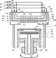
図1および図3は、本実施の形態の気相成長装置の模式断面図である。図2は、本実施の形態のシャワープレートを上方から見る模式平面図である。図1は、図2のEE方向の断面図、図3は、図2のFF方向の断面図である。本実施の形態の気相成長装置は、枚葉型のエピタキシャル成長装置である。 1 and 3 are schematic cross-sectional views of the vapor phase growth apparatus of the present embodiment. FIG. 2 is a schematic plan view of the shower plate according to the present embodiment as viewed from above. 1 is a cross-sectional view in the EE direction of FIG. 2, and FIG. 3 is a cross-sectional view in the FF direction of FIG. The vapor phase growth apparatus of this embodiment is a single wafer type epitaxial growth apparatus.
図1に示すように、本実施の形態のエピタキシャル成長装置は、例えばステンレス製で円筒状中空体の反応室10を備えている。そして、この反応室10上部に配置され、反応室10内に、プロセスガスを供給するシャワープレート200を備えている。 As shown in FIG. 1, the epitaxial growth apparatus of the present embodiment includes a
また、反応室10内のシャワープレート200下方に設けられ、半導体ウェハ(基板)Wを載置可能で回転可能な支持部12を備えている。支持部12は、例えば、中心部に開口部が設けられる環状ホルダー、または、半導体ウェハW裏面のほぼ全面に接する構造のサセプタである。 Moreover, the
また、支持部12をその上面に配置し回転する回転体ユニット14、支持部12に載置されたウェハWを輻射熱により加熱する加熱部16としてヒーターを、支持部12下方に備えている。ここで、回転体ユニット14は、その回転軸18が、下方に位置する回転駆動機構20に接続される。そして、回転駆動機構20により、回転軸18を回転させる。さらに、回転軸18が回転体ユニット14および支持部12を回転させる。これにより、半導体ウェハWをその中心を回転中心として、例えば、数十rpm〜数千rpmで回転させることが可能となっている。 Further, a rotating
円筒状の回転体ユニット14の径は、支持部12の外周径とほぼ同じにしてあることが望ましい。なお、回転軸18は、反応室10の底部に真空シール部材を介して回転自在に設けられている。 The diameter of the cylindrical
そして、加熱部16は、回転軸18の内部に貫通する支持軸22に固定される支持台24上に固定して設けられる。加熱部16には、図示しない電流導入端子と電極により、電力が供給される。この支持台24には半導体ウェハWを環状ホルダー18から脱着させるための、例えば突き上げピン(図示せず)が設けられている。 The
さらに、半導体ウェハW表面等でソースガスが反応した後の反応生成物および反応室10の残留ガスを反応室10外部に排出するガス排出部26を、反応室10底部に備える。なお、ガス排出部26は真空ポンプ(図示せず)に接続してある。 Furthermore, a
そして、本実施の形態のエピタキシャル成長装置は、第1のプロセスガスを供給する第1のガス供給路31、第2のプロセスガスを供給する第2のガス供給路32、第3のプロセスガスを供給する第3のガス供給路33、中央プロセスガスを供給する中央ガス供給路30を備えている。第1のガス供給路31には第1の流量調整部61、第2のガス供給路32には第2の流量調整部62、第3のガス供給路33には第3の流量調整部63、中央ガス供給路30には、中央流量調整部60がそれぞれ接続される。第1の流量調整部61、第2の流量調整部62、第3の流量調整部63、中央流量調整部60は、それぞれ、例えば、マスフローコントローラや流量調整弁、もしくは複数のバルブと複数のマスフローコントローラの組み合わせで構成されているものである。第1の流量調整部61、第2の流量調整部62、第3の流量調整部63、中央流量調整部60は、反応室10に導入される第1ないし第3のプロセスガスおよび中央プロセスガスの流量をそれぞれ独立に制御する。 The epitaxial growth apparatus according to the present embodiment supplies the first
例えば、MOCVD法により、GaNの単結晶膜を半導体ウェハWに成膜する場合、例えば、第1のプロセスガスとして、水素(H2)を分離ガスとして供給する。また、例えば、第2のプロセスガスとして窒素(N)のソースガスとなるアンモニア(NH3)を供給する。また、例えば、第3のプロセスガスとしてGa(ガリウム)のソースガスであるトリメチルガリウム(TMG)をキャリアガスである水素(H2)で希釈したガスを供給する。For example, when a GaN single crystal film is formed on the semiconductor wafer W by MOCVD, for example, hydrogen (H2 ) is supplied as a separation gas as the first process gas. Further, for example, ammonia (NH3 ) serving as a source gas of nitrogen (N) is supplied as the second process gas. Further, for example, a gas obtained by diluting trimethylgallium (TMG), which is a Ga (gallium) source gas, with hydrogen (H2 ), which is a carrier gas, is supplied as a third process gas.
中央プロセスガスは、例えば、第1または第2のプロセスガスと同一種類のプロセスガスである。例えば、中央プロセスガスとして、水素(H2)を分離ガスとして供給する。The central process gas is, for example, the same type of process gas as the first or second process gas. For example, hydrogen (H2 ) is supplied as a separation gas as the central process gas.
ここで、第1のプロセスガスおよび中央プロセスガスである分離ガスとは、第1のガス噴出孔111および中央ガス噴出孔110から噴出させることで、第2のガス噴出孔112から噴出する第2のプロセスガス(ここではアンモニア)と、第3のガス噴出孔113から噴出する第3のプロセスガス(ここではTMG)とを分離するガスである。例えば、第2のプロセスガスおよび第3のプロセスガスと反応性に乏しいガスを用いることが望ましい。上述のように、例えば、水素であり、例えば、窒素、アルゴン等の不活性ガスであってもかまわない。
Here, the separation gas which is the first process gas and the central process gas is the second gas ejected from the second
なお、図1に示した枚葉型エピタキシャル成長装置では、反応室10の側壁箇所において、半導体ウェハを出し入れするための図示しないウェハ出入口およびゲートバルブが設けられている。そして、このゲートバルブで連結する例えばロードロック室(図示せず)と反応室10との間において、ハンドリングアームにより半導体ウェハWを搬送できるように構成される。ここで、例えば合成石英で形成されるハンドリングアームは、シャワープレート200とウェハ支持部12とのスペースに挿入可能となっている。 In the single wafer epitaxial growth apparatus shown in FIG. 1, a wafer inlet / outlet and a gate valve (not shown) for taking in and out a semiconductor wafer are provided at the side wall portion of the
以下、本実施の形態のシャワープレート200について詳細に説明する。図2は、本実施の形態のシャワープレートの模式平面図である。図4は、図2のAA断面図、図5(a)〜(c)は、ぞれぞれ、図2のBB断面図、CC断面図、DD断面図である。 Hereinafter, the
シャワープレート200は、例えば、所定の厚さの板状の形状である。シャワープレート200は、例えば、ステンレス鋼やアルミニウム合金等の金属材料で形成される。シャワープレート200の下面、すなわち、反応室10側の面は円形状を呈する。 The
シャワープレート200の内部には、複数の第1の横方向ガス流路101、複数の第2の横方向ガス流路102、複数の第3の横方向ガス流路103、単一の中央横方向ガス流路100が形成されている。複数の第1の横方向ガス流路101は、第1の水平面(P1)内に配置され互いに平行に延伸する。複数の第2の横方向ガス流路102は、第1の水平面より上方の第2の水平面(P2)内に配置され互いに平行に延伸する。複数の第3の横方向ガス流路103は、第1の水平面より上方、第2の水平面より下方の第3の水平面(P3)内に配置され互いに平行に延伸する。もしくは、の第2の水平面(P2)と第3の水平面(P3)は同じ高さであってもかまわない。中央横方向ガス流路100は、例えば、第1および第2の水平面より上で第2の水平面と同一または上方の水平面内に配置され、第1〜第3の横方向ガス流路101〜103に平行に延伸する。中央横方向ガス流路100の高さは、第1の水平面(P1)等の高さと関連している必要はない。 Inside the
そして、中央横方向ガス流路100は、支持部12の回転中心38直上を通るよう設けられている。すなわち、中央横方向ガス流路100は、シャワープレート200の中心近傍を通り直径方向に沿って形成される。なお、中央横方向ガス流路100は、本発明の効果が期待できる範囲で、支持部12の回転中心38上の近傍を通るよう形成されてもかまわない。 The central lateral
そして、第1の横方向ガス流路101に接続され縦方向に延伸し、反応室10側に第1のガス噴出孔111を有する複数の第1の縦方向ガス流路121を備える。また、第2の横方向ガス流路102に接続され縦方向に延伸し、反応室10側に第2のガス噴出孔112を有する複数の第2の縦方向ガス流路122を備える。第2の縦方向ガス流路122は、第1の横方向ガス流路101の間を通っている。さらに、第3の横方向ガス流路103に接続され縦方向に延伸し、反応室10側に第3のガス噴出孔113を有する複数の第3の縦方向ガス流路123を備える。第3の縦方向ガス流路123は、第1の横方向ガス流路101の間を通っている。また、中央横方向ガス流路100に接続され縦方向に延伸し反応室10側に中央ガス噴出孔110を有する複数の中央縦方向ガス流路120を備える。 A plurality of first
第1の横方向ガス流路101、第2の横方向ガス流路102、第3の横方向ガス流路103は、板状のシャワープレート200内に水平方向に形成された横孔である。また、第1の縦方向ガス流路121、第2の縦方向ガス流路122、第3の縦方向ガス流路123、中央縦方向ガス流路120は、板状のシャワープレート200内に鉛直方向(縦方向または垂直方向)に形成された縦孔である。The first
中央横方向ガス流路100と反応室10との間が第1の透明部材40で形成され、中央縦方向ガス流路120が第1の透明部材40に設けられる縦孔で形成される。また、中央横方向ガス流路100とシャワープレート200上面との間が第2の透明部材42で形成される。さらに、第2の透明部材42上方に、半導体ウェハ(基板)Wの状態を光学的にモニタする計測装置50を備える。計測装置50は、第2の透明部材42上方に複数設けてもかまわない。複数の計測装置50は、異なる計測を行うものでもかまわない。 A space between the central lateral
第1の透明部材40は、計測装置50に用いられる所定の波長に対して透明である部材であり、例えば、石英ガラスを用いることができる。その他、強度が十分あり、透明でプロセスガス等に対する耐性の高い材料であれば、石英ガラス以外の材料、例えば、サファイア等を適用することも可能である。 The first
計測装置50は、例えば、レーザを使って半導体ウェハの反りを測定する反りモニタ装置、もしくは、レーザにより、成長する膜の膜厚や膜質を測定する装置、もしくは、ウェハからの輻射によりウェハの温度を測定する放射温度計等である。 The measuring
このように、中央横方向ガス流路100の上下を透明部材で形成することで、成膜中のウェハ状態を光学的測定により直接観察することが可能となる。したがって、ウェハ温度や、ウェハの反り等の成膜中の制御性が向上する。 Thus, by forming the upper and lower sides of the central lateral
第1、第2、および第3の横方向ガス流路101、102、103の内径は、それぞれ対応する第1、第2、および第3の縦方向ガス流路121、122、123の内径よりも大きくなっている。図4(a)〜(c)では、第1、第2、および第3の横方向ガス流路101、102、103、第1、第2、および第3の縦方向ガス流路121、122、123の断面形状は円形となっているが、円形に限らず、楕円形、矩形、多角形等その他の形状であってもかまわない。また、第1、第2、および第3の横方向ガス流路101、102、103の断面積は、同一でなくてもかまわない。また、第1、第2、および第3の縦方向ガス流路121、122、123の断面積も、同一でなくてもかまわない。 The inner diameters of the first, second, and third lateral
図4では、中央横方向ガス流路100の断面形状は、矩形となっているが、円形、楕円形、多角形等他の形状であってもかまわない。 In FIG. 4, the cross-sectional shape of the central lateral
シャワープレート200は、第1のガス供給路31に接続され、第1の水平面(P1)より上方に設けられる第1のマニフォールド131と、第1のマニフォールド131と第1の横方向ガス流路101とを第1の横方向ガス流路101の端部で接続し縦方向に延伸する第1の接続流路141を備えている。 The
第1のマニフォールド131は、第1のガス供給路31から供給される第1のプロセスガスを、第1の接続流路141を介して複数の第1の横方向ガス流路101に分配する機能を備える。分配された第1のプロセスガスは、複数の第1の縦方向ガス流路121の第1のガス噴出孔111から反応室10に導入される。第1のマニフォールド131はシャワープレート200の側面、もしくは、下面に同様な流量配分を行うように設けてもかまわない。 The
第1のマニフォールド131は、第1の横方向ガス流路101に直交する方向に延伸し、例えば、中空の直方体形状を備える。本実施の形態では、第1のマニフォールド131は、第1の横方向ガス流路101の両端部に設けられるが、いずれか一方の端部に設けられるものであってもかまわない。 The
また、シャワープレート200は、第2のガス供給路32に接続され、第1の水平面(P1)より上方に設けられる第2のマニフォールド132と、第2のマニフォールド132と第2の横方向ガス流路102とを第2の横方向ガス流路102の端部で接続し縦方向に延伸する第2の接続流路142を備えている。 The
第2のマニフォールド132は、第2のガス供給路32から供給される第2のプロセスガスを、第2の接続流路142を介して複数の第2の横方向ガス流路102に分配する機能を備える。分配された第2のプロセスガスは、複数の第2の縦方向ガス流路122の第2のガス噴出孔112から反応室10に導入される。 The
第2のマニフォールド132は、第2の横方向ガス流路102に直交する方向に延伸し、例えば、中空の直方体形状を備える。本実施の形態では、第2のマニフォールド132は、第2の横方向ガス流路102の両端部に設けられるが、いずれか一方の端部に設けられるものであってもかまわない。 The
さらに、シャワープレート200は、第3のガス供給路33に接続され、第1の水平面(P1)より上方に設けられる第3のマニフォールド133と、第3のマニフォールド133と第3の横方向ガス流路103とを第3の横方向ガス流路103の端部で接続し垂直方向に延伸する第3の接続流路143を備えている。 Furthermore, the
第3のマニフォールド133は、第3のガス供給路33から供給される第3のプロセスガスを、第3の接続流路143を介して複数の第3の横方向ガス流路103に分配する機能を備える。分配された第3のプロセスガスは、複数の第3の縦方向ガス流路123の第3のガス噴出孔113から反応室10に導入される。 The
また、シャワープレート200は、一端が中央ガス供給路30に接続され、他端が中央横方向ガス流路100に接続される中央接続流路140を備えている。中央ガス供給路30から供給される中央プロセスガスは、中央接続流路140を介して中央横方向ガス流路100に中央縦方向ガス流路120の中央ガス噴出孔110から反応室10に導入される。 Moreover, the
一般にシャワープレートにプロセスガスの供給口として設けられるガス噴出孔から、反応室10内に噴出するプロセスガスの流量は、成膜の均一性を確保する観点から、各ガス噴出孔間で均一であることが望ましい。本実施の形態のシャワーヘッド100によれば、プロセスガスを複数の横方向ガス流路に分配し、さらに、縦方向ガス流路に分配してガス噴出孔から噴出させる。この構成により、簡便な構造で各ガス噴出孔間から噴出するプロセスガス流量の均一性を向上させることが可能となる。 In general, the flow rate of the process gas ejected into the
また、均一な成膜を行う観点から配置されるガス噴出孔の配置密度はできるだけ大きいことが望ましい。もっとも、本実施の形態のように、互いに平行な複数の横方向ガス流路を設ける構成では、ガス噴出孔の密度を大きくしようとすると、ガス噴出孔の配置密度と横方向ガス流路の内径との間にトレードオフが生じる。 Moreover, it is desirable that the arrangement density of the gas ejection holes arranged from the viewpoint of uniform film formation is as large as possible. However, in the configuration in which a plurality of lateral gas flow paths parallel to each other are provided as in the present embodiment, if the density of the gas ejection holes is increased, the arrangement density of the gas ejection holes and the inner diameter of the lateral gas flow path There is a trade-off between
このため、横方向ガス流路の内径が小さくなることで横方向ガス流路の流体抵抗が上昇し、横方向ガス流路の伸長方向について、ガス噴出孔から噴出するプロセスガス流量の流量分布が大きくなり、各ガス噴出孔間から噴出するプロセスガス流量の均一性が悪化するおそれがある。 For this reason, when the inner diameter of the lateral gas flow path is reduced, the fluid resistance of the lateral gas flow path is increased, and the flow rate distribution of the process gas flow ejected from the gas ejection holes in the extending direction of the lateral gas flow path is There is a risk that the uniformity of the flow rate of the process gas ejected from between the gas ejection holes will deteriorate.
本実施の形態によれば、第1の横方向ガス流路101、第2の横方向ガス流路102および第3の横方向ガス流路103を異なる水平面に設けた階層構造とする。この構造により、横方向ガス流路の内径拡大に対するマージンが向上する。したがって、ガス噴出孔の密度をあげつつ、横方向ガス流路の内径に起因する流量分布拡大を抑制する。よって、結果的に、反応室10内に噴出するプロセスガスの流量分布を均一化し、成膜の均一性を向上させることが可能となる。 According to the present embodiment, the first
また、基板を載置する支持部12を回転させて成膜する構造の気相成長装置の場合、支持部12の回転中心38近傍に成膜される膜の特性、例えば膜厚の制御は困難な場合がある。第2のガス噴出孔112と第3のガス噴出孔113から異なるプロセスガスが供給される場合、支持部12の回転中心38近傍のガス組成が他の部分と異なる場合があるからである。 Further, in the case of a vapor phase growth apparatus having a structure in which a film is formed by rotating the
しかしながら、本実施の形態によれば、回転中心38の直上に中央横方向ガス流路100を設け、この中央横方向ガス流路100に接続され、回転中心38近傍に設けられる中央ガス噴出孔110から独立にプロセスガスを供給することが可能となり、支持部12の回転中心38近傍のガス組成を制御することが可能になる。したがって、支持部12の回転中心38近傍に成膜される膜の特性の制御が容易になり、半導体ウェハ(基板)Wに成膜される膜の膜厚、膜質等の均一性が向上する。 However, according to the present embodiment, the central lateral
中央横方向ガス流路100に設ける中央縦方向ガス流路120および中央ガス噴出孔110は、回転中心38近傍のみに設けられても、直径方向全体にわたって設けられてもかまわない。より、膜特性の均一化を図る観点からは、直径方向全体にわたって設けられことが望ましい。The central vertical
このような枚葉型エピタキシャル気相成長装置を用いて以下のように半導体ウェハ上に気相成長が行われる。本実施の形態の気相成長方法について、GaNをエピタキシャル成長させる場合を例に、図1〜4を用いて説明する。 Using such a single wafer epitaxial vapor phase growth apparatus, vapor phase growth is performed on a semiconductor wafer as follows. The vapor phase growth method of the present embodiment will be described with reference to FIGS. 1 to 4 by taking as an example the case of epitaxially growing GaN.
反応室10にキャリアガスが供給され、図示しない真空ポンプを作動して反応室10内のガスをガス排出部26から排気して、反応室10を所定の圧力に制御している状態で、反応室10内の支持部12に半導体ウェハWを載置する。ここで、例えば、反応室10のウェハ出入口のゲートバルブ(図示せず)を開きハンドリングアームにより、ロードロック室内の半導体ウェハWを反応室10内に搬送する。そして、半導体ウェハWは例えば突き上げピン(図示せず)を介して支持部12に載置され、ハンドリングアームはロードロック室に戻され、ゲートバルブは閉じられる。 A carrier gas is supplied to the
そして、上記真空ポンプによる排気を続行すると共に、回転体ユニット14を所要の速度で回転させながら、第1〜第3のガス噴出孔111、112、113および中央ガス噴出孔110から所定の第1ないし第3のプロセスガスおよび中央プロセスガスを噴出させている。第1のプロセスガスは、第1のガス供給路31から第1のマニュフォールド131、第1の接続流路141、第1の横方向ガス流路101、第1の縦方向ガス流路121を経由して第1のガス噴出孔111から反応室10内に噴出させている。また、第2のプロセスガスは、第2のガス供給路32から第2のマニュフォールド132、第2の接続流路142、第2の横方向ガス流路102、第2の縦方向ガス流路122を経由して第2のガス噴出孔112から反応室10内に噴出させている。また、第3のプロセスガスは、第3のガス供給路33から第3のマニュフォールド133、第3の接続流路143、第3の横方向ガス流路103、第3の縦方向ガス流路123を経由して第3のガス噴出孔113から反応室10内に噴出させている。そして、中央プロセスガスは、中央ガス供給路30から中央ガス接続流路140、中央横方向ガス流路100、中央縦方向ガス流路120を経由して中央ガス噴出孔110から噴出させている。 And while continuing the exhaust_gas | exhaustion by the said vacuum pump, rotating the
支持部12に載置した半導体ウェハWは、加熱部16により所定温度に予備加熱している。さらに、加熱部16の加熱出力を上げて半導体ウェハWをエピタキシャル成長温度に昇温させる。 The semiconductor wafer W placed on the
半導体ウェハW上にGaNを成長させる場合、例えば、第1のプロセスガスおよび中央プロセスガスは分離ガスである水素であり、第2のプロセスガスは窒素のソースガスであるアンモニアであり、第3のプロセスガスはキャリアガスである水素で希釈されたガリウムのソースガスであるTMGである。昇温中は、アンモニアとTMGは反応室10には供給されていない。例えば、第1〜第3のガス噴出孔111、112、113および中央ガス噴出孔110からは、水素ガスのみが供給されている。 When GaN is grown on the semiconductor wafer W, for example, the first process gas and the central process gas are hydrogen as a separation gas, the second process gas is ammonia as a nitrogen source gas, The process gas is TMG which is a source gas of gallium diluted with hydrogen which is a carrier gas. During the temperature increase, ammonia and TMG are not supplied to the
成長温度になってから、第2のガス噴出孔112にアンモニアを供給し、第3のガス噴出孔113にTMGを供給する。第1〜第3のガス噴出孔111、112、113および中央ガス噴出孔110から噴出された第1〜第3のプロセスガスおよび中央プロセスガスは適度に混合されて半導体ウェハW上に整流状態で供給される。これにより、半導体ウェハW表面に、例えば、GaN(ガリウムナイトライド)の単結晶膜がエピタキシャル成長により形成される。 After reaching the growth temperature, ammonia is supplied to the second
そして、エピタキシャル成長終了時には、第3のガス噴出孔113へのTMG供給を停止し、単結晶膜の成長が終了される。 At the end of epitaxial growth, the supply of TMG to the third gas ejection holes 113 is stopped, and the growth of the single crystal film is completed.
成膜後は、半導体ウェハWの降温を始める。所定の温度まで半導体ウェハWの温度が低下してから、第2のガス噴出孔112へのアンモニアを停止する。ここで、例えば、回転体ユニット14の回転を停止させ、単結晶膜が形成された半導体ウェハWを支持部12に載置したままにして、加熱部16の加熱出力を初めに戻し、予備加熱の温度に低下するよう調整する。 After film formation, the temperature of the semiconductor wafer W starts to be lowered. After the temperature of the semiconductor wafer W is lowered to a predetermined temperature, ammonia to the second gas ejection holes 112 is stopped. Here, for example, the rotation of the
次に、半導体ウェハWが所定の温度に安定した後、例えば突き上げピンにより半導体ウェハWを支持部12から脱着させる。そして、再びゲートバルブを開いてハンドリングアームをシャワーヘッド100および支持部12の間に挿入し、その上に半導体ウェハWを載せる。そして、半導体ウェハWを載せたハンドリングアームをロードロック室に戻す。 Next, after the semiconductor wafer W is stabilized at a predetermined temperature, the semiconductor wafer W is detached from the
以上のようにして、一回の半導体ウェハWに対する成膜が終了し、例えば、引き続いて他の半導体ウェハWに対する成膜が上述したのと同一のプロセスシーケンスに従って行うことも可能である。 As described above, film formation on one semiconductor wafer W is completed. For example, film formation on another semiconductor wafer W can be performed in accordance with the same process sequence as described above.
本実施の形態の気相成長方法では、図1〜4に示したエピタキシャル成長装置を用いることで、半導体ウェハWの回転中心近傍に供給される分離ガスを、他の領域とは独立に制御することが可能になる。したがって、成膜上の特異点となる回転中心近傍の成膜特性を他の領域の成膜特性と整合させることが容易となる。したがって、プロセスガスの流れを均一かつ安定にするとともに、回転中心近傍の成膜特性を独立に制御し、基板に膜厚や膜質等の均一性に優れた膜を形成することが可能となる。 In the vapor phase growth method of the present embodiment, the separation gas supplied near the rotation center of the semiconductor wafer W is controlled independently of other regions by using the epitaxial growth apparatus shown in FIGS. Is possible. Therefore, it becomes easy to match the film formation characteristics in the vicinity of the rotation center, which is a singular point in film formation, with the film formation characteristics in other regions. Therefore, the flow of the process gas can be made uniform and stable, and the film formation characteristics in the vicinity of the center of rotation can be independently controlled, so that a film having excellent uniformity such as film thickness and film quality can be formed on the substrate.
(第2の実施の形態)
本実施の形態の気相成長装置は、反応室と、反応室の上部に配置され、反応室内にガスを供給するシャワープレートと、反応室内のシャワープレート下方に設けられ、基板を載置可能な支持部と、を備える気相成長装置である。そして、シャワープレートが、水平面内に配置され互いに平行に延伸する複数の第1の横方向ガス流路と、第1の横方向ガス流路に接続され縦方向に延伸し反応室側に第1のガス噴出孔を有する複数の第1の縦方向ガス流路を備える。また、上記水平面内に配置され第1の横方向ガス流路と同一方向に互いに平行に延伸する複数の第2の横方向ガス流路と、第2の横方向ガス流路に接続され第1の横方向ガス流路の間を通って縦方向に延伸し反応室側に第2のガス噴出孔を有する複数の第2の縦方向ガス流路を備える。そして、第1および第2の横方向ガス流路と同一方向に平行に延伸し、上記支持部の回転中心直上に存在する中央横方向ガス流路と、中央横方向ガス流路に接続され縦方向に延伸し反応室側に中央ガス噴出孔を有する複数の中央縦方向ガス流路と、第1の横方向ガス流路に接続され第1のプロセスガスを供給する第1のガス供給路と、第2の横方向ガス流路に接続され第2のプロセスガスを供給する第2のガス供給路と、中央横方向ガス流路に接続され中央プロセスガスを供給する中央ガス供給路を備える。さらに、第1のガス供給路に接続される第1の流量調整部と、第2のガス供給路に接続される第2の流量調整部と、中央ガス供給路に接続される中央流量調整部と、を備える。(Second Embodiment)
The vapor phase growth apparatus according to the present embodiment is disposed in a reaction chamber, in an upper part of the reaction chamber, and supplies a gas into the reaction chamber. And a support unit. The shower plate is arranged in a horizontal plane and extends in parallel to each other, and a plurality of first lateral gas flow paths are connected to the first lateral gas flow paths and extend in the vertical direction to the reaction chamber side. A plurality of first longitudinal gas flow paths having gas ejection holes are provided. A plurality of second lateral gas passages disposed in the horizontal plane and extending parallel to each other in the same direction as the first lateral gas passage; and a first lateral gas passage connected to the second lateral gas passage. A plurality of second vertical gas flow paths extending in the vertical direction through the horizontal gas flow paths and having second gas ejection holes on the reaction chamber side. The first and second lateral gas flow paths extend in parallel in the same direction, and are connected to the central lateral gas flow path located immediately above the center of rotation of the support portion, and to the central lateral gas flow path. A plurality of central longitudinal gas passages extending in the direction and having a central gas ejection hole on the reaction chamber side, and a first gas supply passage connected to the first lateral gas passage and supplying a first process gas , A second gas supply path connected to the second lateral gas flow path for supplying the second process gas, and a central gas supply path connected to the central lateral gas flow path for supplying the central process gas. Furthermore, a first flow rate adjustment unit connected to the first gas supply path, a second flow rate adjustment unit connected to the second gas supply path, and a central flow rate adjustment unit connected to the central gas supply path And comprising.
本実施の形態の気相成長装置は、第1および第2の横方向ガス流路が、同一水平面に配置され、階層構造を備えない点で上記第1の実施の形態と異なっている。本実施の形態においても、プロセスガスの流れを均一かつ安定にし、回転中心近傍の成膜特性を独立に制御することで、基板に膜厚や膜質等の均一性に優れた膜を形成することが可能となる。 The vapor phase growth apparatus of the present embodiment is different from the first embodiment in that the first and second lateral gas flow paths are arranged on the same horizontal plane and do not have a hierarchical structure. Also in this embodiment, a film having excellent uniformity in film thickness, film quality, etc. can be formed on the substrate by making the flow of process gas uniform and stable and independently controlling the film formation characteristics near the rotation center. Is possible.
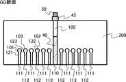
以下、本実施の形態のシャワープレート200について詳細に説明する。図6は、本実施の形態のシャワープレートの模式平面図である。図7は、図6のGG断面図、図8(a)〜(c)は、ぞれぞれ、図6のHH断面図、II断面図、JJ断面図である。 Hereinafter, the
シャワープレート200は、例えば、所定の厚さの板状の形状である。シャワープレート200は、例えば、ステンレス鋼やアルミニウム合金等の金属材料で形成される。シャワープレート200の下面、すなわち、反応室10側の面は円形状を呈する。 The
シャワープレート200の内部には、複数の第1の横方向ガス流路101、複数の第2の横方向ガス流路102、複数の第3の横方向ガス流路103、単一の中央横方向ガス流路100が形成されている。複数の第1の横方向ガス流路101、複数の第2の横方向ガス流路102、複数の第3の横方向ガス流路103は、同一の水平面内に配置され互いに平行に延伸する。中央横方向ガス流路100は、例えば、第1および第2の水平面より上で第2の水平面と同一または上方の水平面内に配置され、第1〜第3の横方向ガス流路101〜103に平行に延伸する。 Inside the
そして、中央横方向ガス流路100は、支持部12の回転中心38直上を通るよう設けられている。すなわち、中央横方向ガス流路100は、シャワープレート200の中心近傍を通り直径方向に沿って形成される。支持部12の回転中心38直上とは、支持部12の回転中心38から支持部12の上面に対し垂直な方向の上方である。 The central lateral
そして、第1の横方向ガス流路101に接続され縦方向に延伸し、反応室10側に第1のガス噴出孔111を有する複数の第1の縦方向ガス流路121を備える。また、第2の横方向ガス流路102に接続され縦方向に延伸し、反応室10側に第2のガス噴出孔112を有する複数の第2の縦方向ガス流路122を備える。さらに、第3の横方向ガス流路103に接続され縦方向に延伸し、反応室10側に第3のガス噴出孔113を有する複数の第3の縦方向ガス流路123を備える。また、中央横方向ガス流路100に接続され縦方向に延伸し反応室10側に中央ガス噴出孔110を有する複数の中央縦方向ガス流路120を備える。 A plurality of first
第1の横方向ガス流路101、第2の横方向ガス流路102、第3の横方向ガス流路103、板状のシャワープレート200内に水平方向に形成された横孔である。また、第1の縦方向ガス流路121、第2の縦方向ガス流路122、第3の縦方向ガス流路123、中央縦方向ガス流路120は、板状のシャワープレート200内に鉛直方向(縦方向または垂直方向)に形成された縦孔である。 The first
中央横方向ガス流路100と反応室10との間が第1の透明部材40で形成され、中央縦方向ガス流路120が第1の透明部材40に設けられる縦孔で形成される。また、中央横方向ガス流路100とシャワープレート200上面との間が第2の透明部材42で形成される。さらに、第2の透明部材42上方に、半導体ウェハ(基板)Wの状態を光学的にモニタする計測装置50を備える。計測装置50は、第2の透明部材42上方に複数設けてもかまわない。複数の計測装置50は、異なる計測を行うものでもかまわない。 A space between the central lateral
第1の透明部材40は、計測装置50に用いられる所定の波長に対して透明である部材であり、例えば、石英ガラスを用いることができる。その他、強度が十分あり、透明でプロセスガス等に対する耐性の高い材料であれば、石英ガラス以外の材料、例えば、サファイア等を適用することも可能である。 The first
計測装置50は、例えば、レーザを使って半導体ウェハの反りを測定する反りモニタ装置、もしくは、レーザにより、成長する膜の膜厚や膜質を測定する装置、もしくは、ウェハからの輻射によりウェハの温度を測定する放射温度計等である。 The measuring
このように、中央横方向ガス流路100の上下を透明部材で形成することで、成膜中のウェハ状態を光学的測定により直接観察することが可能となる。したがって、ウェハ温度や、ウェハの反り等の成膜中の制御性が向上する。 Thus, by forming the upper and lower sides of the central lateral
第1、第2、および第3の横方向ガス流路101、102、103の内径は、それぞれ対応する第1、第2、および第3の縦方向ガス流路121、122、123の内径よりも大きくなっている。図8(a)〜(c)では、第1、第2、および第3の横方向ガス流路101、102、103、第1、第2、および第3の縦方向ガス流路121、122、123の断面形状は円形となっているが、円形に限らず、楕円形、矩形、多角形等その他の形状であってもかまわない。また、第1、第2、および第3の横方向ガス流路101、102、103の断面積は、同一でなくてもかまわない。また、第1、第2、および第3の縦方向ガス流路121、122、123の断面積も、同一でなくてもかまわない。 The inner diameters of the first, second, and third lateral
図4では、中央横方向ガス流路100の断面形状は、矩形となっているが、円形、楕円形、多角形等他の形状であってもかまわない。 In FIG. 4, the cross-sectional shape of the central lateral
シャワープレート200は、第1のガス供給路31に接続され、第1の水平面(P1)より上方に設けられる第1のマニフォールド131と、第1のマニフォールド131と第1の横方向ガス流路101とを第1の横方向ガス流路101の端部で接続し縦方向に延伸する第1の接続流路141を備えている。 The
第1のマニフォールド131は、第1のガス供給路31から供給される第1のプロセスガスを、第1の接続流路141を介して複数の第1の横方向ガス流路101に分配する機能を備える。分配された第1のプロセスガスは、複数の第1の縦方向ガス流路121の第1のガス噴出孔111から反応室10に導入される。第1のマニフォールド131はシャワープレート200の側面、もしくは、下面に同様な流量配分を行うように設けてもかまわない。 The
第1のマニフォールド131は、第1の横方向ガス流路101に直交する方向に延伸し、例えば、中空の直方体形状を備える。本実施の形態では、第1のマニフォールド131は、第1の横方向ガス流路101の両端部に設けられるが、いずれか一方の端部に設けられるものであってもかまわない。 The
また、シャワープレート200は、第2のガス供給路32に接続され、第1の水平面(P1)より上方に設けられる第2のマニフォールド132と、第2のマニフォールド132と第2の横方向ガス流路102とを第2の横方向ガス流路102の端部で接続し縦方向に延伸する第2の接続流路142を備えている。 The
第2のマニフォールド132は、第2のガス供給路32から供給される第2のプロセスガスを、第2の接続流路142を介して複数の第2の横方向ガス流路102に分配する機能を備える。分配された第2のプロセスガスは、複数の第2の縦方向ガス流路122の第2のガス噴出孔112から反応室10に導入される。 The
第2のマニフォールド132は、第2の横方向ガス流路102に直交する方向に延伸し、例えば、中空の直方体形状を備える。本実施の形態では、第2のマニフォールド132は、第2の横方向ガス流路102の両端部に設けられるが、いずれか一方の端部に設けられるものであってもかまわない。 The
さらに、シャワープレート200は、第3のガス供給路33に接続され、第1の水平面(P1)より上方に設けられる第3のマニフォールド133と、第3のマニフォールド133と第3の横方向ガス流路103とを第3の横方向ガス流路103の端部で接続し垂直方向に延伸する第3の接続流路143を備えている。 Furthermore, the
第3のマニフォールド133は、第3のガス供給路33から供給される第3のプロセスガスを、第3の接続流路143を介して複数の第3の横方向ガス流路103に分配する機能を備える。分配された第3のプロセスガスは、複数の第3の縦方向ガス流路123の第3のガス噴出孔113から反応室10に導入される。 The
また、シャワープレート200は、一端が中央ガス供給路30に接続され、他端が中央横方向ガス流路100に接続される中央接続流路140を備えている。中央ガス供給路30から供給される中央プロセスガスは、中央接続流路140を介して中央横方向ガス流路100に中央縦方向ガス流路120の中央ガス噴出孔110から反応室10に導入される。 Moreover, the
なお、成膜中のウェハ(基板)状態を光学的測定により直接観察することを可能にする観点から、中央横方向ガス流路と反応室との間が第1の透明部材で形成され、中央縦方向ガス流路が第1の透明部材に設けられる縦孔で形成され、中央横方向ガス流路とシャワープレート上面との間が第2の透明部材で形成されることが望ましい。 From the viewpoint of enabling direct observation of the wafer (substrate) state during film formation by optical measurement, the first transparent member is formed between the central lateral gas flow path and the reaction chamber. It is desirable that the vertical gas channel is formed by a vertical hole provided in the first transparent member, and the second transparent member is formed between the central horizontal gas channel and the upper surface of the shower plate.
また、第2の透明部材上方に基板の状態を光学的にモニタする計測装置を備えることが望ましい。 Moreover, it is desirable to provide a measuring device for optically monitoring the state of the substrate above the second transparent member.
また、第1および第2の透明部材が石英ガラスであることが望ましい。 Moreover, it is desirable that the first and second transparent members are quartz glass.
さらに、中央プロセスガスが、第1または第2のプロセスガスと、同一種類のガスであることが望ましい。 Furthermore, it is desirable that the central process gas is the same type of gas as the first or second process gas.
以上、具体例を参照しつつ本発明の実施の形態について説明した。上記、実施の形態はあくまで、例として挙げられているだけであり、本発明を限定するものではない。また、各実施の形態の構成要素を適宜組み合わせてもかまわない。 The embodiments of the present invention have been described above with reference to specific examples. The above embodiment is merely given as an example, and does not limit the present invention. Further, the constituent elements of the respective embodiments may be appropriately combined.
例えば、中央プロセスガスを分離ガスとする場合を例に説明したが、ソースガス等その他のガス種としてもかまわない。中央プロセスガスを分離ガスとする場合、第2のガス噴出孔112と第3のガス噴出孔113から異なるプロセスガスが供給される場合、支持部12の回転中心38近傍のガス組成を制御しやすい。 For example, although the case where the central process gas is the separation gas has been described as an example, other gas species such as a source gas may be used. When the central process gas is the separation gas, when different process gases are supplied from the second
例えば、実施の形態では横方向ガス流路等の流路を4系統設ける場合を例に説明したが、横方向ガス流路等の流路を5系統以上設けても、2系統または3系統であってもかまわない。 For example, in the embodiment, the case where four channels such as the lateral gas channel are provided has been described as an example. However, even when five or more channels such as the lateral gas channel are provided, two or three channels are provided. It does not matter.
また、例えば、実施の形態では、GaN(窒化ガリウム)の単結晶膜を成膜する場合を例に説明したが、例えば、Si(珪素)やSiC(炭化珪素)の単結晶膜等を成膜にも本発明を適用することが可能である。基板はサファイア、SiC、シリコン等が用いられる。AlN(窒化アルミニウム)を成長させるときは、原料ガスのアンモニアとトリメチルアルミニウム(TMA)が気相中で容易に反応し、AlNの粉を生成したり、アンモニアとTMAの重合体がAlN膜の膜質を悪化させたりする。分離ガスを供給することにより、気相でのアンモニアとTMAの反応を抑制し、AlNの膜質を向上させることが可能になる。この場合も中央プロセスガスを分離ガスとする場合の方が、支持部12の回転中心38近傍の膜質や膜厚を制御しやすい。 For example, in the embodiment, the case where a single crystal film of GaN (gallium nitride) is formed has been described as an example. However, for example, a single crystal film of Si (silicon) or SiC (silicon carbide) is formed. The present invention can also be applied to. As the substrate, sapphire, SiC, silicon or the like is used. When growing AlN (aluminum nitride), the source gas ammonia and trimethylaluminum (TMA) react easily in the gas phase to produce AlN powder, or the polymer of ammonia and TMA is the film quality of the AlN film. Worsen. By supplying the separation gas, the reaction between ammonia and TMA in the gas phase can be suppressed, and the film quality of AlN can be improved. Also in this case, it is easier to control the film quality and film thickness in the vicinity of the
また、実施の形態では、ウェハ1枚毎に成膜する枚葉式のエピタキシャル装置を例に説明したが、気相成長装置は、枚葉式のエピタキシャル装置に限られるものではない。例えば、自公転する複数のウェハに同時に成膜するプラネタリー方式のCVD装置等にも、本発明を適用することが可能である。 Further, in the embodiment, the single-wafer type epitaxial apparatus for forming a film for each wafer has been described as an example, but the vapor phase growth apparatus is not limited to the single-wafer type epitaxial apparatus. For example, the present invention can also be applied to a planetary CVD apparatus that simultaneously forms a film on a plurality of wafers that rotate and revolve.
実施の形態では、装置構成や製造方法等、本発明の説明に直接必要しない部分等については記載を省略したが、必要とされる装置構成や製造方法等を適宜選択して用いることができる。その他、本発明の要素を具備し、当業者が適宜設計変更しうる全ての気相成長装置は、本発明の範囲に包含される。本発明の範囲は、特許請求の範囲およびその均等物の範囲によって定義されるものである。 In the embodiments, description of the apparatus configuration, the manufacturing method, and the like that are not directly necessary for the description of the present invention is omitted, but the required apparatus configuration, the manufacturing method, and the like can be appropriately selected and used. In addition, all vapor phase growth apparatuses that include the elements of the present invention and can be appropriately modified by those skilled in the art are included in the scope of the present invention. The scope of the present invention is defined by the appended claims and equivalents thereof.
10 反応室
12 支持部
18 回転軸
30 中央ガス供給路
31 第1のガス供給路
32 第2のガス供給路
33 第3のガス供給路
40 第1の透明部材
42 第2の透明部材
50 計測装置
60 中央流量調整部
61 第1の流量調整部
62 第2の流量調整部
63 第3の流量調整部
100 中央横方向ガス供給路
101 第1の横方向ガス流路
102 第2の横方向ガス流路
103 第3の横方向ガス流路
110 中央ガス噴出孔
111 第1のガス噴出孔
112 第2のガス噴出孔
113 第3のガス噴出孔
120 中央縦方向ガス流路
121 第1の縦方向ガス流路
122 第2の縦方向ガス流路
123 第3の縦方向ガス流路
200 シャワープレートDESCRIPTION OF
Claims (5)
Translated fromJapanese第1のプロセスガスを供給する第1のガス供給路と、
第2のプロセスガスを供給する第2のガス供給路と、
前記反応室内に設けられ、基板を載置可能な支持部と、
前記反応室の上部に配置され、前記反応室内にガスを供給するシャワープレートであって、
前記第1のガス供給路に接続される一対の第1のマニフォールドと、前記一対の第1のマニフォールドより下方の第1の水平面内に配置され互いに平行に延伸する複数の第1の横方向ガス流路と、前記一対の第1のマニフォールドと前記第1の横方向ガス流路とを前記第1の横方向ガス流路の両端部で接続し縦方向に延伸する第1の接続流路と、前記第1の横方向ガス流路に接続され縦方向に延伸し前記反応室側に第1のガス噴出孔を有する複数の第1の縦方向ガス流路と、
前記第2のガス供給路に接続され、前記第1の水平面より上方に設けられる一対の第2のマニフォールドと、前記第1の水平面より上方で前記一対の第2のマニフォールドより下方の第2の水平面内に配置され前記第1の横方向ガス流路と同一方向に互いに平行に延伸する複数の第2の横方向ガス流路と、前記一対の第2のマニフォールドと前記第2の横方向ガス流路とを前記第2の横方向ガス流路の両端部で接続し縦方向に延伸する第2の接続流路と、前記第2の横方向ガス流路に接続され前記第1の横方向ガス流路の間を通って縦方向に延伸し前記反応室側に第2のガス噴出孔を有する複数の第2の縦方向ガス流路と、
前記第1および第2の横方向ガス流路と同一方向に平行に延伸し、前記支持部の回転中心直上を通る中央横方向ガス流路と、前記中央横方向ガス流路に接続され縦方向に延伸し前記反応室側に中央ガス噴出孔を有する複数の中央縦方向ガス流路と、を備えるシャワープレートと、
前記中央横方向ガス流路に接続され中央プロセスガスを供給する中央ガス供給路と、
前記第1のガス供給路に接続される第1の流量調整部と、
前記第2のガス供給路に接続される第2の流量調整部と、
前記中央ガス供給路に接続される中央流量調整部と、
を備えることを特徴とする気相成長装置。A reaction chamber;
A first gas supply path for supplying a first process gas;
A second gas supply path for supplying a second process gas;
A support provided in the reaction chamber and on which a substrate can be placed;
A shower plate disposed at the top of the reaction chamber for supplying gas into the reaction chamber;
A pair of first manifolds connected to the first gas supply path, and a plurality of first lateral gases disposed in a first horizontal planebelow the pair of first manifolds and extending parallel to each other A flow path, afirst connection flow path that connects the pair of first manifolds and the first lateral gas flow path at both ends of the first lateral gas flow path and extends in the vertical direction A plurality of first longitudinal gas passages connected to the first transverse gas passage and extending in the longitudinal direction and having a first gas ejection hole on the reaction chamber side;
A pair of second manifolds connected to the second gas supply path and provided above the first horizontal plane, and asecond lower than the pair of second manifolds above the first horizontal plane. A plurality of second lateral gas passages disposed in a horizontal plane and extending in parallel with each other in the same direction as the first lateral gas passage; thepair of second manifolds; and the second lateral gas. A second connecting channel extending in the longitudinal direction by connecting a channel to both ends of the second lateral gas channel, and the first lateral direction connected to the second lateral gas channel. A plurality of second vertical gas flow paths extending in the vertical direction through the gas flow paths and having second gas ejection holes on the reaction chamber side;
A central lateral gas passage extending in parallel with the first and second lateral gas passages in the same direction and passing immediately above the center of rotation of the support, and a longitudinal direction connected to the central transverse gas passage A plurality of central longitudinal gas flow paths extending to the reaction chamber and having a central gas ejection hole on the reaction chamber side, and a shower plate,
A central gas supply path connected to the central lateral gas flow path for supplying a central process gas;
A first flow rate adjusting unit connected to the first gas supply path;
A second flow rate adjustment unit connected to the second gas supply path;
A central flow rate adjusting unit connected to the central gas supply path;
A vapor phase growth apparatus comprising:
前記中央縦方向ガス流路が前記第1の透明部材に設けられる縦孔で形成され、
前記中央横方向ガス流路と前記シャワープレート上面との間が第2の透明部材で形成されることを特徴とする請求項1記載の気相成長装置。A space between the central lateral gas flow path and the reaction chamber is formed by a first transparent member,
The central longitudinal gas flow path is formed by a longitudinal hole provided in the first transparent member;
The vapor phase growth apparatus according to claim 1, wherein a space between the central lateral gas flow path and the upper surface of the shower plate is formed by a second transparent member.
5. The vapor phase growth apparatus according to claim 1, wherein the central process gas is the same type of gas as the first or second process gas. 6.
Priority Applications (4)
| Application Number | Priority Date | Filing Date | Title |
|---|---|---|---|
| JP2013124847AJP6199619B2 (en) | 2013-06-13 | 2013-06-13 | Vapor growth equipment |
| TW103117491ATWI574306B (en) | 2013-06-13 | 2014-05-19 | Gas growth device |
| US14/301,703US9803282B2 (en) | 2013-06-13 | 2014-06-11 | Vapor phase growth apparatus |
| KR1020140072118AKR101699815B1 (en) | 2013-06-13 | 2014-06-13 | Vapor phase growing apparatus |
Applications Claiming Priority (1)
| Application Number | Priority Date | Filing Date | Title |
|---|---|---|---|
| JP2013124847AJP6199619B2 (en) | 2013-06-13 | 2013-06-13 | Vapor growth equipment |
Publications (3)
| Publication Number | Publication Date |
|---|---|
| JP2015002208A JP2015002208A (en) | 2015-01-05 |
| JP2015002208A5 JP2015002208A5 (en) | 2016-06-30 |
| JP6199619B2true JP6199619B2 (en) | 2017-09-20 |
Family
ID=52018122
Family Applications (1)
| Application Number | Title | Priority Date | Filing Date |
|---|---|---|---|
| JP2013124847AActiveJP6199619B2 (en) | 2013-06-13 | 2013-06-13 | Vapor growth equipment |
Country Status (4)
| Country | Link |
|---|---|
| US (1) | US9803282B2 (en) |
| JP (1) | JP6199619B2 (en) |
| KR (1) | KR101699815B1 (en) |
| TW (1) | TWI574306B (en) |
Families Citing this family (15)
| Publication number | Priority date | Publication date | Assignee | Title |
|---|---|---|---|---|
| JP6199619B2 (en)* | 2013-06-13 | 2017-09-20 | 株式会社ニューフレアテクノロジー | Vapor growth equipment |
| KR102215965B1 (en)* | 2014-04-11 | 2021-02-18 | 주성엔지니어링(주) | Apparatus for injection gas and apparatus for processing substrate including the same |
| JP6193284B2 (en)* | 2015-03-18 | 2017-09-06 | 株式会社東芝 | Channel structure, intake / exhaust member, and processing apparatus |
| US10438795B2 (en) | 2015-06-22 | 2019-10-08 | Veeco Instruments, Inc. | Self-centering wafer carrier system for chemical vapor deposition |
| NL2015215B1 (en) | 2015-07-23 | 2017-02-08 | Meyer Burger (Netherlands) B V | Programmable deposition apparatus. |
| USD810705S1 (en) | 2016-04-01 | 2018-02-20 | Veeco Instruments Inc. | Self-centering wafer carrier for chemical vapor deposition |
| USD819580S1 (en) | 2016-04-01 | 2018-06-05 | Veeco Instruments, Inc. | Self-centering wafer carrier for chemical vapor deposition |
| US20180077430A1 (en) | 2016-09-09 | 2018-03-15 | Barrie Hansen | Cloned Video Streaming |
| JP2018107156A (en)* | 2016-12-22 | 2018-07-05 | 株式会社ニューフレアテクノロジー | Vapor growth apparatus and vapor growth method |
| TWI754765B (en)* | 2017-08-25 | 2022-02-11 | 美商應用材料股份有限公司 | Inject assembly for epitaxial deposition processes |
| US11149350B2 (en)* | 2018-01-10 | 2021-10-19 | Asm Ip Holding B.V. | Shower plate structure for supplying carrier and dry gas |
| CN108195607A (en)* | 2018-02-02 | 2018-06-22 | 中国科学院西安光学精密机械研究所 | Mars surface environment simulation test device and method |
| KR102641752B1 (en)* | 2018-11-21 | 2024-03-04 | 삼성전자주식회사 | Gas injection module, substrate processing apparatus and method for manufacturing semiconductor device using the same |
| KR20210150978A (en)* | 2020-06-03 | 2021-12-13 | 에이에스엠 아이피 홀딩 비.브이. | Shower plate, substrate treatment device, and substrate treatment method |
| CN120138791A (en)* | 2023-12-12 | 2025-06-13 | 中微半导体设备(上海)股份有限公司 | Air intake device and vapor deposition equipment |
Family Cites Families (53)
| Publication number | Priority date | Publication date | Assignee | Title |
|---|---|---|---|---|
| US3701682A (en)* | 1970-07-02 | 1972-10-31 | Texas Instruments Inc | Thin film deposition system |
| JP3360098B2 (en)* | 1995-04-20 | 2002-12-24 | 東京エレクトロン株式会社 | Shower head structure of processing equipment |
| JPH0945624A (en)* | 1995-07-27 | 1997-02-14 | Tokyo Electron Ltd | Leaf-type heat treating system |
| JPH10158841A (en)* | 1996-11-27 | 1998-06-16 | Shibaura Eng Works Co Ltd | Vapor phase growth equipment |
| GB9712400D0 (en)* | 1997-06-16 | 1997-08-13 | Trikon Equip Ltd | Shower head |
| US6302964B1 (en)* | 1998-06-16 | 2001-10-16 | Applied Materials, Inc. | One-piece dual gas faceplate for a showerhead in a semiconductor wafer processing system |
| US6086677A (en)* | 1998-06-16 | 2000-07-11 | Applied Materials, Inc. | Dual gas faceplate for a showerhead in a semiconductor wafer processing system |
| US6206972B1 (en)* | 1999-07-08 | 2001-03-27 | Genus, Inc. | Method and apparatus for providing uniform gas delivery to substrates in CVD and PECVD processes |
| JP4487338B2 (en)* | 1999-08-31 | 2010-06-23 | 東京エレクトロン株式会社 | Film forming apparatus and film forming method |
| JP3962509B2 (en)* | 1999-09-16 | 2007-08-22 | 株式会社東芝 | Vapor growth equipment |
| KR20010062209A (en) | 1999-12-10 | 2001-07-07 | 히가시 데쓰로 | Processing apparatus with a chamber having therein a high-etching resistant sprayed film |
| JP4703810B2 (en)* | 2000-03-07 | 2011-06-15 | 東京エレクトロン株式会社 | CVD film forming method |
| US6533867B2 (en)* | 2000-11-20 | 2003-03-18 | Applied Epi Inc | Surface sealing showerhead for vapor deposition reactor having integrated flow diverters |
| KR100427996B1 (en)* | 2001-07-19 | 2004-04-28 | 주식회사 아이피에스 | Apparatus and method for depositing thin film on wafer |
| JP3990881B2 (en)* | 2001-07-23 | 2007-10-17 | 株式会社日立製作所 | Semiconductor manufacturing apparatus and cleaning method thereof |
| US7383841B2 (en)* | 2002-07-05 | 2008-06-10 | Tokyo Electron Limited | Method of cleaning substrate-processing device and substrate-processing device |
| US7018940B2 (en)* | 2002-12-30 | 2006-03-28 | Genus, Inc. | Method and apparatus for providing uniform gas delivery to substrates in CVD and PECVD processes |
| JP4306403B2 (en)* | 2003-10-23 | 2009-08-05 | 東京エレクトロン株式会社 | Shower head structure and film forming apparatus using the same |
| KR100513920B1 (en)* | 2003-10-31 | 2005-09-08 | 주식회사 시스넥스 | Chemical vapor deposition unit |
| KR100731164B1 (en)* | 2005-05-19 | 2007-06-20 | 주식회사 피에조닉스 | Apparatus of chemical vapor deposition with a shower head and method therof |
| JP4344949B2 (en)* | 2005-12-27 | 2009-10-14 | セイコーエプソン株式会社 | Shower head, film forming apparatus including shower head, and method for manufacturing ferroelectric film |
| JP5069427B2 (en)* | 2006-06-13 | 2012-11-07 | 北陸成型工業株式会社 | Shower plate, and plasma processing apparatus, plasma processing method and electronic device manufacturing method using the same |
| KR100849929B1 (en)* | 2006-09-16 | 2008-08-26 | 주식회사 피에조닉스 | Chemical vapor deposition method and apparatus equipped with a shower head for actively controlling the injection speed of the reaction gas |
| JP4981485B2 (en)* | 2007-03-05 | 2012-07-18 | 株式会社ニューフレアテクノロジー | Vapor phase growth method and vapor phase growth apparatus |
| JP5034594B2 (en)* | 2007-03-27 | 2012-09-26 | 東京エレクトロン株式会社 | Film forming apparatus, film forming method, and storage medium |
| US20090095222A1 (en)* | 2007-10-16 | 2009-04-16 | Alexander Tam | Multi-gas spiral channel showerhead |
| US20090095221A1 (en)* | 2007-10-16 | 2009-04-16 | Alexander Tam | Multi-gas concentric injection showerhead |
| US7976631B2 (en)* | 2007-10-16 | 2011-07-12 | Applied Materials, Inc. | Multi-gas straight channel showerhead |
| CN105420688B (en)* | 2008-12-04 | 2019-01-22 | 威科仪器有限公司 | Air inlet element and its manufacturing method for chemical vapor deposition |
| US20110048325A1 (en)* | 2009-03-03 | 2011-03-03 | Sun Hong Choi | Gas Distribution Apparatus and Substrate Processing Apparatus Having the Same |
| JP2010238810A (en)* | 2009-03-30 | 2010-10-21 | Sharp Corp | Vapor phase growth method and vapor phase growth apparatus for III-V compound semiconductor thin film crystal |
| KR101064210B1 (en)* | 2009-06-01 | 2011-09-14 | 한국생산기술연구원 | Shower head for membrane deposition vacuum equipment |
| JP5560093B2 (en)* | 2009-06-30 | 2014-07-23 | 株式会社日立国際電気 | Substrate processing apparatus, semiconductor device manufacturing method, and substrate manufacturing method |
| US20110030615A1 (en)* | 2009-08-04 | 2011-02-10 | Applied Materials, Inc. | Method and apparatus for dry cleaning a cooled showerhead |
| US20110117728A1 (en)* | 2009-08-27 | 2011-05-19 | Applied Materials, Inc. | Method of decontamination of process chamber after in-situ chamber clean |
| WO2011044451A2 (en)* | 2009-10-09 | 2011-04-14 | Applied Materials, Inc. | Multi-gas centrally cooled showerhead design |
| US8409352B2 (en)* | 2010-03-01 | 2013-04-02 | Hitachi Kokusai Electric Inc. | Method of manufacturing semiconductor device, method of manufacturing substrate and substrate processing apparatus |
| US20110244663A1 (en)* | 2010-04-01 | 2011-10-06 | Applied Materials, Inc. | Forming a compound-nitride structure that includes a nucleation layer |
| US20110256692A1 (en)* | 2010-04-14 | 2011-10-20 | Applied Materials, Inc. | Multiple precursor concentric delivery showerhead |
| US20120000490A1 (en)* | 2010-07-01 | 2012-01-05 | Applied Materials, Inc. | Methods for enhanced processing chamber cleaning |
| US8460466B2 (en)* | 2010-08-02 | 2013-06-11 | Veeco Instruments Inc. | Exhaust for CVD reactor |
| JP5715361B2 (en)* | 2010-09-08 | 2015-05-07 | 東京エレクトロン株式会社 | Cleaning method |
| JP5476269B2 (en) | 2010-09-29 | 2014-04-23 | 東京エレクトロン株式会社 | Film forming method and film forming apparatus |
| JP6038618B2 (en)* | 2011-12-15 | 2016-12-07 | 株式会社ニューフレアテクノロジー | Film forming apparatus and film forming method |
| WO2013136482A1 (en)* | 2012-03-15 | 2013-09-19 | 株式会社島津製作所 | Discharge ionization current detector and method for aging treatment of same |
| CN103388132B (en)* | 2012-05-11 | 2015-11-25 | 中微半导体设备(上海)有限公司 | Gas shower head, its manufacturing method and thin film growth reactor |
| JP6134522B2 (en)* | 2013-01-30 | 2017-05-24 | 株式会社ニューフレアテクノロジー | Vapor growth apparatus and vapor growth method |
| JP6199619B2 (en)* | 2013-06-13 | 2017-09-20 | 株式会社ニューフレアテクノロジー | Vapor growth equipment |
| JP6157942B2 (en)* | 2013-06-13 | 2017-07-05 | 株式会社ニューフレアテクノロジー | Vapor growth apparatus and vapor growth method |
| JP6153401B2 (en)* | 2013-07-02 | 2017-06-28 | 株式会社ニューフレアテクノロジー | Vapor growth apparatus and vapor growth method |
| JP6180208B2 (en)* | 2013-07-08 | 2017-08-16 | 株式会社ニューフレアテクノロジー | Vapor growth apparatus and vapor growth method |
| US9214340B2 (en)* | 2014-02-05 | 2015-12-15 | Applied Materials, Inc. | Apparatus and method of forming an indium gallium zinc oxide layer |
| US9502242B2 (en)* | 2014-02-05 | 2016-11-22 | Applied Materials, Inc. | Indium gallium zinc oxide layers for thin film transistors |
- 2013
- 2013-06-13JPJP2013124847Apatent/JP6199619B2/enactiveActive
- 2014
- 2014-05-19TWTW103117491Apatent/TWI574306B/enactive
- 2014-06-11USUS14/301,703patent/US9803282B2/enactiveActive
- 2014-06-13KRKR1020140072118Apatent/KR101699815B1/enactiveActive
Also Published As
| Publication number | Publication date |
|---|---|
| KR20140145564A (en) | 2014-12-23 |
| US9803282B2 (en) | 2017-10-31 |
| JP2015002208A (en) | 2015-01-05 |
| KR101699815B1 (en) | 2017-01-25 |
| US20140366803A1 (en) | 2014-12-18 |
| TW201511085A (en) | 2015-03-16 |
| TWI574306B (en) | 2017-03-11 |
Similar Documents
| Publication | Publication Date | Title |
|---|---|---|
| JP6199619B2 (en) | Vapor growth equipment | |
| JP6134522B2 (en) | Vapor growth apparatus and vapor growth method | |
| JP6157942B2 (en) | Vapor growth apparatus and vapor growth method | |
| KR101640918B1 (en) | Vapor growth device and vapor growth method | |
| JP6606403B2 (en) | Shower plate, vapor phase growth apparatus, and vapor phase growth method | |
| JP6370630B2 (en) | Vapor growth apparatus and vapor growth method | |
| JP6386901B2 (en) | Vapor growth apparatus and vapor growth method | |
| JP6153401B2 (en) | Vapor growth apparatus and vapor growth method | |
| JP2014146767A5 (en) | ||
| KR20130043399A (en) | Chemical vapor deposition apparatus | |
| US20130152853A1 (en) | Film-forming apparatus and film-forming method | |
| JP2016081945A (en) | Vapor growth apparatus and vapor growth method | |
| US20100307418A1 (en) | Vapor phase epitaxy apparatus of group iii nitride semiconductor | |
| KR20150101236A (en) | Modular Chemical Vapor Deposition individually controlling supply gas | |
| JP2017135170A (en) | Vapor growth apparatus and vapor growth method | |
| JP2012124326A (en) | Compound semiconductor epitaxial wafer manufacturing apparatus |
Legal Events
| Date | Code | Title | Description |
|---|---|---|---|
| A521 | Request for written amendment filed | Free format text:JAPANESE INTERMEDIATE CODE: A523 Effective date:20160511 | |
| A621 | Written request for application examination | Free format text:JAPANESE INTERMEDIATE CODE: A621 Effective date:20160511 | |
| A977 | Report on retrieval | Free format text:JAPANESE INTERMEDIATE CODE: A971007 Effective date:20170228 | |
| A131 | Notification of reasons for refusal | Free format text:JAPANESE INTERMEDIATE CODE: A131 Effective date:20170307 | |
| A521 | Request for written amendment filed | Free format text:JAPANESE INTERMEDIATE CODE: A523 Effective date:20170501 | |
| TRDD | Decision of grant or rejection written | ||
| A01 | Written decision to grant a patent or to grant a registration (utility model) | Free format text:JAPANESE INTERMEDIATE CODE: A01 Effective date:20170808 | |
| A61 | First payment of annual fees (during grant procedure) | Free format text:JAPANESE INTERMEDIATE CODE: A61 Effective date:20170824 | |
| R150 | Certificate of patent or registration of utility model | Ref document number:6199619 Country of ref document:JP Free format text:JAPANESE INTERMEDIATE CODE: R150 | |
| R250 | Receipt of annual fees | Free format text:JAPANESE INTERMEDIATE CODE: R250 | |
| R250 | Receipt of annual fees | Free format text:JAPANESE INTERMEDIATE CODE: R250 | |
| R250 | Receipt of annual fees | Free format text:JAPANESE INTERMEDIATE CODE: R250 | |
| R250 | Receipt of annual fees | Free format text:JAPANESE INTERMEDIATE CODE: R250 | |
| R250 | Receipt of annual fees | Free format text:JAPANESE INTERMEDIATE CODE: R250 | |
| R250 | Receipt of annual fees | Free format text:JAPANESE INTERMEDIATE CODE: R250 |