JP6199014B2 - Lens unit and image pickup apparatus having the same - Google Patents
Lens unit and image pickup apparatus having the sameDownload PDFInfo
- Publication number
- JP6199014B2 JP6199014B2JP2012165849AJP2012165849AJP6199014B2JP 6199014 B2JP6199014 B2JP 6199014B2JP 2012165849 AJP2012165849 AJP 2012165849AJP 2012165849 AJP2012165849 AJP 2012165849AJP 6199014 B2JP6199014 B2JP 6199014B2
- Authority
- JP
- Japan
- Prior art keywords
- shim
- unit
- lens
- lens barrel
- image sensor
- Prior art date
- Legal status (The legal status is an assumption and is not a legal conclusion. Google has not performed a legal analysis and makes no representation as to the accuracy of the status listed.)
- Expired - Fee Related
Links
- 238000003384imaging methodMethods0.000claimsdescription38
- 230000003287optical effectEffects0.000claimsdescription9
- 238000012937correctionMethods0.000description15
- 239000004417polycarbonateSubstances0.000description5
- 238000012423maintenanceMethods0.000description3
- 239000000758substrateSubstances0.000description3
- 230000005484gravityEffects0.000description2
- 239000000463materialSubstances0.000description2
- 238000000034methodMethods0.000description2
- 229920000139polyethylene terephthalatePolymers0.000description2
- 239000005020polyethylene terephthalateSubstances0.000description2
- 229920006324polyoxymethylenePolymers0.000description2
- 229910000838Al alloyInorganic materials0.000description1
- 229930182556PolyacetalNatural products0.000description1
- NIXOWILDQLNWCW-UHFFFAOYSA-Nacrylic acid groupChemical groupC(C=C)(=O)ONIXOWILDQLNWCW-UHFFFAOYSA-N0.000description1
- 239000003086colorantSubstances0.000description1
- 238000013461designMethods0.000description1
- 238000010586diagramMethods0.000description1
- 238000006073displacement reactionMethods0.000description1
- 238000007689inspectionMethods0.000description1
- 239000004973liquid crystal related substanceSubstances0.000description1
- 238000004519manufacturing processMethods0.000description1
- 229910052751metalInorganic materials0.000description1
- 239000002184metalSubstances0.000description1
- 238000012986modificationMethods0.000description1
- 230000004048modificationEffects0.000description1
- 238000000465mouldingMethods0.000description1
- 230000002093peripheral effectEffects0.000description1
- 229920000515polycarbonatePolymers0.000description1
- -1polyethylene terephthalatePolymers0.000description1
- 229920005989resinPolymers0.000description1
- 239000011347resinSubstances0.000description1
- 230000004044responseEffects0.000description1
- 229920005992thermoplastic resinPolymers0.000description1
Images


Classifications
- G—PHYSICS
- G02—OPTICS
- G02B—OPTICAL ELEMENTS, SYSTEMS OR APPARATUS
- G02B7/00—Mountings, adjusting means, or light-tight connections, for optical elements
- G02B7/02—Mountings, adjusting means, or light-tight connections, for optical elements for lenses
- G02B7/023—Mountings, adjusting means, or light-tight connections, for optical elements for lenses permitting adjustment
- H—ELECTRICITY
- H04—ELECTRIC COMMUNICATION TECHNIQUE
- H04N—PICTORIAL COMMUNICATION, e.g. TELEVISION
- H04N23/00—Cameras or camera modules comprising electronic image sensors; Control thereof
- H04N23/50—Constructional details
- H04N23/55—Optical parts specially adapted for electronic image sensors; Mounting thereof
- G—PHYSICS
- G02—OPTICS
- G02B—OPTICAL ELEMENTS, SYSTEMS OR APPARATUS
- G02B13/00—Optical objectives specially designed for the purposes specified below
- G02B13/16—Optical objectives specially designed for the purposes specified below for use in conjunction with image converters or intensifiers, or for use with projectors, e.g. objectives for projection TV
- G—PHYSICS
- G03—PHOTOGRAPHY; CINEMATOGRAPHY; ANALOGOUS TECHNIQUES USING WAVES OTHER THAN OPTICAL WAVES; ELECTROGRAPHY; HOLOGRAPHY
- G03B—APPARATUS OR ARRANGEMENTS FOR TAKING PHOTOGRAPHS OR FOR PROJECTING OR VIEWING THEM; APPARATUS OR ARRANGEMENTS EMPLOYING ANALOGOUS TECHNIQUES USING WAVES OTHER THAN OPTICAL WAVES; ACCESSORIES THEREFOR
- G03B17/00—Details of cameras or camera bodies; Accessories therefor
- G03B17/02—Bodies
- G—PHYSICS
- G03—PHOTOGRAPHY; CINEMATOGRAPHY; ANALOGOUS TECHNIQUES USING WAVES OTHER THAN OPTICAL WAVES; ELECTROGRAPHY; HOLOGRAPHY
- G03B—APPARATUS OR ARRANGEMENTS FOR TAKING PHOTOGRAPHS OR FOR PROJECTING OR VIEWING THEM; APPARATUS OR ARRANGEMENTS EMPLOYING ANALOGOUS TECHNIQUES USING WAVES OTHER THAN OPTICAL WAVES; ACCESSORIES THEREFOR
- G03B43/00—Testing correct operation of photographic apparatus or parts thereof
- H—ELECTRICITY
- H04—ELECTRIC COMMUNICATION TECHNIQUE
- H04N—PICTORIAL COMMUNICATION, e.g. TELEVISION
- H04N23/00—Cameras or camera modules comprising electronic image sensors; Control thereof
- H04N23/50—Constructional details
- H04N23/54—Mounting of pick-up tubes, electronic image sensors, deviation or focusing coils
- G—PHYSICS
- G02—OPTICS
- G02B—OPTICAL ELEMENTS, SYSTEMS OR APPARATUS
- G02B7/00—Mountings, adjusting means, or light-tight connections, for optical elements
- G02B7/02—Mountings, adjusting means, or light-tight connections, for optical elements for lenses
Landscapes
- Physics & Mathematics (AREA)
- General Physics & Mathematics (AREA)
- Optics & Photonics (AREA)
- Engineering & Computer Science (AREA)
- Multimedia (AREA)
- Signal Processing (AREA)
- Lens Barrels (AREA)
- Studio Devices (AREA)
- Camera Bodies And Camera Details Or Accessories (AREA)
Description
Translated fromJapanese本発明は、撮像素子とレンズ鏡筒とのアオリ調整を容易に行なうことのできるレンズユニット及びこれを具えた撮像装置に関するものである。 The present invention relates to a lens unit that can easily adjust the tilt between an image pickup element and a lens barrel, and an image pickup apparatus including the lens unit.
CCDやCMOS等の撮像素子により得られた画像や動画の撮像信号をデジタル画像データに変換し、メモリなどに記憶したり、液晶表示部に表示するデジタルカメラなどの撮像装置が知られている。 An imaging device such as a digital camera that converts an image or moving image imaging signal obtained by an imaging element such as a CCD or CMOS into digital image data and stores it in a memory or displays it on a liquid crystal display unit is known.
この種の撮像装置では、撮像素子の撮像面の中心が、レンズ鏡筒内に配置されたレンズの光軸と一致し、また、撮像面とレンズ光軸が垂直となるように、撮像素子をレンズ鏡筒に取り付けなければならない。 In this type of image pickup device, the image pickup device is arranged so that the center of the image pickup surface of the image pickup device coincides with the optical axis of the lens arranged in the lens barrel and the image pickup surface and the lens optical axis are perpendicular to each other. Must be attached to the lens barrel.
撮像素子のレンズ鏡筒への取付けは、撮像素子の取り付けられた素子取付プレートをレンズ鏡筒へ取り付けることにより行なわれる。しかしながら、撮像素子や素子取付プレート、レンズやレンズ鏡筒などの各部品には個体間に製造上のバラツキがあるから、単にこれらを組み立てただけでは、撮像素子の撮像面がレンズ光軸に対して傾いてしまうことがある。このため、撮像素子の取付角度をレンズ鏡筒に対して傾き調整する所謂チルト調整を行なう必要がある。 The image sensor is attached to the lens barrel by attaching an element attachment plate to which the image sensor is attached to the lens barrel. However, because there are variations in manufacturing among individual parts such as the image sensor, the element mounting plate, the lens, and the lens barrel, simply assembling these parts causes the imaging surface of the image sensor to face the lens optical axis. May tilt. Therefore, it is necessary to perform so-called tilt adjustment in which the mounting angle of the image sensor is adjusted with respect to the lens barrel.
また、チルト調整と共に、撮像素子とレンズ鏡筒との間の距離を調整する所謂フランジバック調整を行なう必要がある。 In addition to the tilt adjustment, it is necessary to perform a so-called flange back adjustment for adjusting the distance between the image sensor and the lens barrel.
そこで、特許文献1では、素子取付プレートとレンズ鏡筒の間に複数のバネを嵌装すると共に、撮像素子をレンズ鏡筒に複数のネジで取り付けた構成を開示しており、測定機器を用いて出力画像を参照しながら、各ネジの締付量を調整することで、チルト調整とフランジバック調整(以下、これらをまとめて「アオリ調整」と称する)を行なっている。 Therefore, Patent Document 1 discloses a configuration in which a plurality of springs are fitted between the element mounting plate and the lens barrel, and the imaging element is attached to the lens barrel with a plurality of screws. The tilt adjustment and the flange back adjustment (hereinafter collectively referred to as “tilt adjustment”) are performed by adjusting the tightening amount of each screw while referring to the output image.
しかしながら、撮像素子等は非常に小さい部品であり、このアオリ調整を行なうために、複数の微小なバネを装着する作業は非常に困難である。また、微小なバネはバネ強さにバラツキがあるから、そのバラツキによりアオリ調整が困難となることもある。 However, the image sensor and the like are very small parts, and it is very difficult to mount a plurality of minute springs in order to perform the tilt adjustment. In addition, since the minute spring has a variation in spring strength, it may be difficult to adjust the tilt due to the variation.
また、出力画像を参照しながらアオリ調整しているから、調整作業に非常に時間が掛かってしまうこととなる。 Further, since the tilt adjustment is performed while referring to the output image, the adjustment work takes a very long time.
そこで、バネに代えて複数枚のシムを重ねて配置し、アオリ調整を行なうことも提案されている。 In view of this, it has also been proposed to place a plurality of shims in place of the springs and perform tilt adjustment.
しかしながら、シムも薄く微小な部品であるため、個々のシムをレンズ鏡筒に載せる作業は非常に困難であり、また、組立ての際にシムを取り付けるときや、メンテナンスのために撮像素子をレンズ鏡筒から取り外したときに、シムがレンズ鏡筒内に落下すると、その取出しはほぼ不能である。 However, since the shim is also a thin and minute part, it is very difficult to place individual shims on the lens barrel. Also, when installing the shim during assembly or for maintenance purposes, the image sensor is attached to the lens mirror. If the shim falls into the lens barrel when it is removed from the tube, its removal is almost impossible.
本発明の目的は、撮像素子とレンズ鏡筒とのアオリ調整を容易に行なうことのできるレンズユニット及びこれを具えた撮像装置を提供することである。 An object of the present invention is to provide a lens unit that can easily adjust the tilt between an image sensor and a lens barrel, and an image pickup apparatus including the lens unit.
本発明に係るレンズユニットは、
内部にレンズを収容し、光軸の通過する矩形の撮像窓の開設されたレンズ鏡筒と、
撮像素子と、一方の面に撮像素子が装着された素子取付プレートを具える撮像素子ユニットと、を具え、
前記撮像窓と前記撮像素子が対向するように、前記レンズ鏡筒に前記撮像素子ユニットを複数のネジにより取り付けてなるレンズユニットであって、
前記レンズ鏡筒と前記素子取付プレートとの間には、前記撮像窓の周縁に取り付けられ、前記撮像窓の少なくとも2辺に沿う形状を有するシムベースと、該シムベースの1又は複数箇所に夫々1又は複数装着されるシムからなるシムユニットが配備されている。The lens unit according to the present invention is
A lens barrel that houses a lens and has a rectangular imaging window through which the optical axis passes;
An image sensor, and an image sensor unit comprising an element mounting plate having the image sensor mounted on one surface thereof,
A lens unit in which the imaging element unit is attached to the lens barrel with a plurality of screws so that the imaging window and the imaging element face each other;
Between the lens barrel and the element mounting plate, a shim base that is attached to the periphery of the imaging window and has a shape along at least two sides of the imaging window, and one or more portions of the shim base, respectively, There are shim units consisting of multiple shims.
本発明に係るレンズユニットは、1又は複数のシムをシムベースに載置したシムユニットにより、アオリ調整を容易に行なうことができる。
シムは、予めシムベースに載置することができるから、シムを個々にレンズ鏡筒に配置する必要がない。従って、レンズユニットの組立てやメンテナンスの際にシムがレンズ鏡筒に落下すること等を防止できる。In the lens unit according to the present invention, the tilt adjustment can be easily performed by the shim unit in which one or a plurality of shims are mounted on the shim base.
Since the shim can be previously placed on the shim base, it is not necessary to individually place the shim on the lens barrel. Accordingly, it is possible to prevent the shim from dropping into the lens barrel during the assembly and maintenance of the lens unit.
本発明は、アオリ調整を容易に行なうことのできるレンズユニット(20)及びこれを具えた撮像装置(10)に関し、予めアオリ調整のための補正量を算出して、算出された補正量に基づいて、アオリ調整に用いられるシムユニット(40)の厚さを予め調整した上で、レンズユニット(20)の組立てを行なうようにしたものである。 The present invention relates to a lens unit (20) capable of easily performing tilt adjustment and an imaging device (10) including the lens unit (20), and calculates a correction amount for tilt adjustment in advance, and based on the calculated correction amount The lens unit (20) is assembled after the thickness of the shim unit (40) used for tilt adjustment is adjusted in advance.
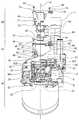
本発明の一実施形態として、レンズユニット(20)は、図1に示すように、筺体(11)の前面側に取り付けられて、デジタルカメラ等の画像や動画を撮像する撮像装置(10)を構成する。 As an embodiment of the present invention, as shown in FIG. 1, the lens unit (20) is attached to the front side of the housing (11) and includes an imaging device (10) for capturing images and moving images of a digital camera or the like. Configure.
図2は、レンズユニット(20)の分解斜視図である。レンズユニット(20)は、内部に1又は複数枚の撮像レンズを収容した筒状のレンズ鏡筒(30)と、撮像面(61)を有する撮像素子(62)を素子取付プレート(77)に取り付けて構成される撮像素子ユニット(60)との間に、アオリ調整を行なうシムユニット(40)を具える。 FIG. 2 is an exploded perspective view of the lens unit (20). The lens unit (20) includes a cylindrical lens barrel (30) containing one or a plurality of imaging lenses therein and an imaging element (62) having an imaging surface (61) as an element mounting plate (77). A shim unit (40) for adjusting the tilt is provided between the image pickup device unit (60) and the mounting unit.
レンズ鏡筒(30)は、図2に示すように、基端側に撮像レンズを通過した光を撮像素子(62)へ導く矩形の撮像窓(33)が開設されており、該撮像窓(33)の周縁は、シムユニット(40)と撮像素子ユニット(60)が取り付けられるユニット取付面(31)となっている。 As shown in FIG. 2, the lens barrel (30) is provided with a rectangular imaging window (33) for guiding light that has passed through the imaging lens to the imaging element (62) on the proximal end side. The peripheral edge of 33) is a unit mounting surface (31) to which the shim unit (40) and the image sensor unit (60) are mounted.
ユニット取付面(31)の一実施形態として、図2に示すように、矩形の撮像窓(33)の頂点の内、3つの頂点の近傍にアオリ調整ユニット(40)と撮像素子ユニット(60)をネジ止めするためのネジ孔(34)の形成されたボス(32)を突設している。より具体的には、これらボス(32)は、矩形の撮像窓(33)の重心(G)を中心とする円上に配置される。 As an embodiment of the unit mounting surface (31), as shown in FIG. 2, among the vertices of the rectangular imaging window (33), the tilt adjustment unit (40) and the image sensor unit (60) are arranged near the three vertices. A boss (32) formed with a screw hole (34) for screwing is provided. More specifically, these bosses (32) are arranged on a circle centered on the center of gravity (G) of the rectangular imaging window (33).
これらボス(32)の先端をアオリ調整の基準面(37)として採用することができる。この基準面(37)は、ボス(32)(32)(32)と対応する3カ所の位置が夫々、後述するシム(51)が載置されて位置決めされるシム搭載位置(38α)(38β)(38γ)となる。なお、前記重心(G)から基準面(37)に下ろされた垂線との交点をレンズ鏡筒(30)の設計中心(X)と称する。 The tips of these bosses (32) can be used as the reference plane (37) for tilt adjustment. The reference surface (37) has three positions corresponding to the bosses (32), (32), and (32), and shim mounting positions (38α) (38β) on which shims (51) to be described later are placed. ) (38γ). The intersection point with the perpendicular line drawn from the center of gravity (G) to the reference plane (37) is referred to as the design center (X) of the lens barrel (30).
また、ユニット取付面(31)には、矩形の撮像窓(33)を略対角状に横切るように、アオリ調整ユニット(40)及び撮像素子ユニット(60)を位置決めするためのガイド(35)(36)が突設されている。 Further, on the unit mounting surface (31), a guide (35) for positioning the tilt adjustment unit (40) and the image sensor unit (60) so as to cross the rectangular imaging window (33) substantially diagonally. (36) is projected.
シムユニット(40)は、図2に示すように、矩形の撮像窓(33)の少なくとも2辺に沿う形状を有するシムベース(47)と、該シムベース(47)に載置される1又は複数のシム(51)(厚さ調整部材)を具える。 As shown in FIG. 2, the shim unit (40) includes a shim base (47) having a shape along at least two sides of a rectangular imaging window (33), and one or more mounted on the shim base (47). A shim (51) (thickness adjusting member) is provided.
図示の実施例では、シムベース(47)は、前述のユニット取付面(31)に形成されたアオリ調整の基準面(37)となるボス(32)上に配置される。シムベース(47)は、例えば略L字状とすることができ、ネジ孔(34)とガイド(35)(36)に被さる形状としている。シムベース(47)として、薄くて撓みにくい樹脂材料を採用することができる。なお、シムベース(47)の厚さをD1とする(図7参照)。 In the illustrated embodiment, the shim base (47) is disposed on a boss (32) serving as a reference plane (37) for tilt adjustment formed on the unit mounting surface (31). The shim base (47) can be, for example, substantially L-shaped, and has a shape that covers the screw hole (34) and the guides (35), (36). As the shim base (47), a resin material that is thin and hardly bends can be employed. The thickness of the shim base (47) is D1 (see FIG. 7).
シムベース(47)には、ネジ孔(34)と対向する位置に夫々ネジ孔(34)よりも径の大きいルーズ孔(44)が開設されている。このルーズ孔(44)の形成されている部分が、後述するシム(51)の取付位置となる。図示の実施例では、ルーズ孔(44)は3カ所に形成されているから、シム(51)も最大3カ所に載置することができる。 In the shim base (47), a loose hole (44) having a diameter larger than that of the screw hole (34) is formed at a position facing the screw hole (34). A portion where the loose hole (44) is formed is a mounting position of a shim (51) described later. In the illustrated embodiment, the loose holes (44) are formed in three places, so that the shims (51) can also be placed in a maximum of three places.
また、シムベース(47)には、ガイド(35)(36)と対向する位置にガイド(35)(36)に夫々嵌まるガイド孔(45)(46)が開設されている。一方のガイド孔(46)は、図3及び図4に示すように長孔形状としており、シムユニット(40)等のバラツキを許容し、ユニット取付面(31)に取り付けたときに、位置決めし易いようにしている。 The shim base (47) is provided with guide holes (45) and (46) that respectively fit into the guides (35) and (36) at positions facing the guides (35) and (36). One guide hole (46) has a long hole shape as shown in FIGS. 3 and 4, and allows for variation in the shim unit (40), etc., and is positioned when attached to the unit mounting surface (31). It is made easy.
シムベース(47)には、ルーズ孔(44)の周縁に、載置される1又は複数のシム(51)を位置決めするための位置決め機構となる位置決め突起(48)(49)が突設されている。 Positioning projections (48) and (49) that serve as a positioning mechanism for positioning one or more shims (51) to be placed are provided on the shim base (47) at the periphery of the loose hole (44). Yes.
シムベース(47)に載置されるシム(51)は、図3乃至図6に示すように、前述したシムベース(47)のルーズ孔(44)と重なるルーズ孔(54)が開設された薄板状のリング部材とすることができる。なお、シム(51)のルーズ孔(54)は、シムベース(47)のルーズ孔(44)よりも少し小径とすることで、ルーズ孔(54)にバリがあった場合に厚さ調整への影響を抑えることができる。
シム(51)には、シムベース(47)へ位置決めするための位置決め機構となる位置決め孔(58)(59)がルーズ孔(54)の周縁に開設されている。As shown in FIGS. 3 to 6, the
In the shim (51), positioning holes (58) and (59) serving as a positioning mechanism for positioning to the shim base (47) are formed at the periphery of the loose hole (54).
図示の実施例では、位置決め機構となる位置決め突起(48)の断面を角丸長方形、位置決め突起(49)の断面を円形として、位置決め突起(48)と位置決め突起(49)の形状を変えている。また、これに対応して、シム(51)に形成された位置決め孔(58)と位置決め孔(59)の形状も角丸長方形と円形としている。このように、位置決め突起(48)(49)と位置決め孔(58)(59)の形状を変えることで、シム(51)の表裏の取付ミスを防ぐことができる。 In the illustrated embodiment, the positioning protrusion (48) serving as a positioning mechanism has a rounded rectangular cross section and the positioning protrusion (49) has a circular cross section, and the shapes of the positioning protrusion (48) and the positioning protrusion (49) are changed. . Correspondingly, the shape of the positioning hole (58) and the positioning hole (59) formed in the shim (51) is also a rounded rectangle and a circle. In this way, by changing the shapes of the positioning protrusions (48) and (49) and the positioning holes (58) and (59), it is possible to prevent mounting errors on the front and back of the shim (51).
シム(51)について、さらに詳細に説明を行なうと、シム(51)は、荷重が加わっても厚みが変形し難い薄い材料を採用することができ、例えば、PET(ポリエチレンテレフタレート)、POM(ポリアセタール)、PC(ポリカーボネート)、アクリルなどの熱可塑性樹脂を例示できる。 The shim (51) will be described in more detail. The shim (51) can employ a thin material that does not easily deform its thickness even when a load is applied. For example, PET (polyethylene terephthalate), POM (polyacetal) ), Thermoplastic resins such as PC (polycarbonate) and acrylic.
シム(51)は、アオリ調整を行なうために、複数の厚さを有するものを選択できるようにすることが望ましい。例えば、シム(51)の厚さ(D2)は、38μm、75μm、125μm及び188μmの4種類とすることができる。
シム(51)の厚さ(D2)を外観で見分けることができるように、シム(51)の色を夫々変えたり、図5及び図6に示すように、厚さに応じて、シム(51)の周縁に切欠き(56)を形成することが望ましい。例えば、上記4種類の厚さのシム(51)であれば、色を2種類、切欠き(56)の数を図5に示すように1つ、図6に示すように2つとすることで、外観により4種類の厚さのシム(51)を見分けることができる。It is desirable that the shim (51) can be selected from a plurality of thicknesses in order to adjust the tilt. For example, the thickness (D2) of the shim (51) can be four types of 38 μm, 75 μm, 125 μm, and 188 μm.
In order to distinguish the thickness (D2) of the shim (51) by appearance, the color of the shim (51) is changed, or as shown in FIGS. 5 and 6, the shim (51 It is desirable to form a notch (56) at the periphery of For example, if the shim (51) has the four types of thicknesses, two types of colors, one notch (56) as shown in FIG. 5, and two as shown in FIG. The four different thickness shims (51) can be distinguished by their appearance.
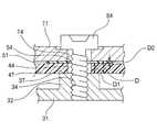
シム(51)は、調整すべきチルト角度及びフランジバック量に応じて、単体又は複数種類を組み合わせて使用することができ、図7に示すように、シムベース(47)の厚さ(D1)とシム(51)の厚さ(D2)の合計(D)が、シムユニット(40)のアオリ調整のための厚さとなる。
勿論、アオリ調整が不要の場合はシムベース(47)にシム(51)を載置しないこともできる。The shim (51) can be used alone or in combination of a plurality of types according to the tilt angle to be adjusted and the flange back amount. As shown in FIG. 7, the thickness (D1) of the shim base (47) The sum (D) of the thickness (D2) of the shim (51) is the thickness for adjusting the tilt of the shim unit (40).
Of course, when the tilt adjustment is not required, the shim (51) may not be placed on the shim base (47).
上記構成のシムユニット(40)は、調整すべきチルト角度及びフランジバック量に応じて、シムベース(47)の位置決め突起(48)(49)に、選択されたシム(51)の位置決め孔(58)(59)を嵌めて使用される。 The shim unit (40) having the above configuration has the positioning holes (58) of the selected shim (51) in the positioning protrusions (48) (49) of the shim base (47) according to the tilt angle to be adjusted and the flange back amount. ) (59) is used.
シムユニット(40)は、図4に示すように、予めシムベース(47)にシム(51)を載置した状態で、図2及び図7に示すように、シムベース(47)のガイド孔(45)(46)を、レンズ鏡筒(30)のユニット取付面(31)のガイド(35)(36)に夫々嵌めることで、ユニット取付面(31)に取り付けされる。 As shown in FIG. 4, the shim unit (40) has the shim base (47) previously placed on the shim base (47), as shown in FIG. 2 and FIG. ) And (46) are respectively fitted to the guides (35) and (36) of the unit mounting surface (31) of the lens barrel (30) to be mounted on the unit mounting surface (31).
シムユニット(40)をユニット取付面(31)に取り付けた状態で、その上から撮像素子ユニット(60)が取り付けられる。 With the shim unit (40) attached to the unit attachment surface (31), the image sensor unit (60) is attached from above.
撮像素子ユニット(60)は、図2に示すように、アルミニウム合金等の金属製の素子取付プレート(77)の一方の面に、センサ基板(63)を介してCCDやCMOSなど、撮像面(61)を有する撮像素子(62)を取り付けて構成することができる。センサ基板(63)は、フレキシブル基板(65)等により、撮像装置(10)の制御系に電気的に接続することができる。 As shown in FIG. 2, the image pickup element unit (60) has an image pickup surface (such as a CCD or CMOS) on one surface of a metal element attachment plate (77) such as an aluminum alloy via a sensor substrate (63). An image pickup device (62) having 61) can be attached. The sensor substrate (63) can be electrically connected to the control system of the imaging device (10) by a flexible substrate (65) or the like.
素子取付プレート(77)には、前述したユニット取付面(31)のネジ孔(34)に対応した位置に夫々ネジ孔(34)よりも径の大きいルーズ孔(74)が開設されている。また、ユニット取付面(31)のガイド(35)(36)と対応した位置にガイド孔(75)(76)が開設されている。なお、ガイド孔(76)は、撮像素子ユニット(60)等の成型精度のバラツキを許容し、位置決めを容易にするために長孔形状としている。 In the element mounting plate (77), loose holes (74) each having a diameter larger than that of the screw hole (34) are formed at positions corresponding to the screw holes (34) of the unit mounting surface (31). Further, guide holes (75) and (76) are formed at positions corresponding to the guides (35) and (36) on the unit mounting surface (31). The guide hole (76) has a long hole shape to allow variation in molding accuracy of the image sensor unit (60) and the like and to facilitate positioning.
上記構成の撮像素子ユニット(60)は、図2及び図7に示すように、レンズ鏡筒(30)にシムユニット(40)を取り付けた状態で、ガイド(35)(36)にガイド孔(75)(76)を嵌め、ルーズ孔(74)にネジ(84)を挿通し、ネジ(84)をユニット取付面(31)のネジ孔(34)にネジ止めされて、レンズユニット(20)を作製することができる。 As shown in FIGS. 2 and 7, the image pickup device unit (60) having the above-described configuration is provided with guide holes (35) and (36) in the guide holes (35) and (36) with the shim unit (40) attached to the lens barrel (30). 75) (76) is inserted, screw (84) is inserted into loose hole (74), screw (84) is screwed into screw hole (34) of unit mounting surface (31), and lens unit (20) Can be produced.
前記ネジ(84)に沿う拡大断面図を参照するとわかるとおり、ユニット取付面(31)の基準面(37)となるボス(32)上にシムユニット(40)が載置され、該シムユニット(40)のシム(51)上に撮像素子ユニット(60)が載置されることとなる。 As can be seen by referring to the enlarged sectional view along the screw (84), the shim unit (40) is placed on the boss (32) which becomes the reference surface (37) of the unit mounting surface (31), and the shim unit ( The image sensor unit (60) is placed on the shim (51) of 40).
本発明では、レンズ鏡筒(30)の光軸Aのずれと、撮像素子ユニット(60)のずれに応じて、シムユニット(40)の厚さ(D)を決定し、シムユニット(40)が所望の厚さ(D)となるように、シム搭載位置(38α)(38β)(38γ)におけるシム(51)を選択し、予めシムベース(47)にシム(51)を載置しておくことができる。従って、レンズユニット(20)の組立ての際には単にレンズ鏡筒(30)のユニット取付面(31)にシムユニット(40)を載せ、続いて撮像素子ユニット(60)を載せてネジ(84)止めするだけで、撮像素子ユニット(60)の取付けと同時にアオリ調整も行なうことができる。 In the present invention, the thickness (D) of the shim unit (40) is determined according to the deviation of the optical axis A of the lens barrel (30) and the deviation of the image sensor unit (60), and the shim unit (40). The shim (51) at the shim mounting positions (38α), (38β), and (38γ) is selected so that the desired thickness (D) is obtained, and the shim (51) is previously placed on the shim base (47). be able to. Therefore, when the lens unit (20) is assembled, the shim unit (40) is simply placed on the unit mounting surface (31) of the lens barrel (30), and then the image sensor unit (60) is placed on the screw (84). ) Just by stopping, the tilt adjustment can be performed simultaneously with the mounting of the image sensor unit (60).
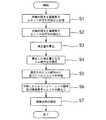
上記構成のレンズ鏡筒(30)、シムユニット(40)及び撮像素子ユニット(60)は、フローチャート図8に示す要領で組み立てることができる。 The lens barrel (30), shim unit (40) and image sensor unit (60) having the above-described configuration can be assembled in the manner shown in the flowchart of FIG.
レンズ鏡筒(30)の光軸(図2中矢印Aで示す)の傾き(ずれ)と、撮像素子ユニット(60)の素子取付プレート(77)と撮像面(61)との平行度(ずれ)を予め測定する。 The inclination (deviation) of the optical axis (indicated by arrow A in FIG. 2) of the lens barrel (30) and the parallelism (deviation) between the element mounting plate (77) of the image sensor unit (60) and the imaging surface (61). ) In advance.
レンズ鏡筒(30)の光軸Aの傾きは、シムユニット(40)と当接するボス(32)の基準面(37)の設計中心(X)からの厚さ方向のずれを補正量(C1)とすることができる。 The inclination of the optical axis A of the lens barrel (30) is a correction amount (C1) for the deviation in the thickness direction from the design center (X) of the reference surface (37) of the boss (32) in contact with the shim unit (40). ).
撮像素子ユニット(60)のずれは、撮像面(61)の高さ情報に基づいて、素子取付プレート(77)の前記ボス(32)にネジ(84)止めされるルーズ孔(74)の設計中心(前記基準面(37)の設計中心(X)と対向する位置)からの厚さ方向のずれを補正量(C2)とすることができる。 The image sensor unit (60) shift is based on the height information of the image pickup surface (61), and the design of the loose hole (74) to be screwed (84) to the boss (32) of the element mounting plate (77) Deviation in the thickness direction from the center (position facing the design center (X) of the reference surface (37)) can be used as the correction amount (C2).
測定されたずれの情報は、個々のレンズ鏡筒(30)と撮像素子ユニット(60)毎にQR(Quick Response)情報(39)(69)として、シールなどでレンズ鏡筒(30)と撮像素子ユニット(60)に付しておく。また、管制PC(90)にその情報を記憶しておく(ステップS1及び図9)。 The measured deviation information is taken as the QR (Quick Response) information (39) (69) for each lens barrel (30) and image sensor unit (60), and the lens barrel (30) is imaged with a seal or the like. It is attached to the element unit (60). Further, the information is stored in the control PC (90) (step S1 and FIG. 9).
なお、上記ずれの情報は、QR情報ではなく、バーコードとすることもできる。また、管制PC(90)にレンズ鏡筒(30)と撮像素子ユニット(60)の個々の機器番号と、対応するずれの情報を記憶しておくこともできる。 Note that the information on the deviation may be a barcode instead of the QR information. The control PC (90) can also store the individual device numbers of the lens barrel (30) and the image sensor unit (60) and the corresponding deviation information.
レンズユニット(20)を組み立てる際には、まず、複数のレンズ鏡筒(30)と、複数の撮像素子ユニット(60)の中から、夫々1つずつレンズ鏡筒(30)と撮像素子ユニット(60)を取り出してペアとする。 When the lens unit (20) is assembled, first, the lens barrel (30) and the image sensor unit (1) are respectively selected from the plurality of lens barrels (30) and the plurality of image sensor units (60). Take 60) and make a pair.
ペアとされたレンズ鏡筒(30)と撮像素子ユニット(60)は、夫々のQR情報を光学的に読み出す(ステップS2)。読み出されたQR情報は、図9に示す管制PC(90)のQRコード(登録商標)情報取得部(91)に送られる。 The paired lens barrel (30) and image pickup device unit (60) optically read out the respective QR information (step S2). The read QR information is sent to the QR code (registered trademark) information acquisition unit (91) of the control PC (90) shown in FIG.
演算回路(93)は、QRコード情報取得部(91)にて得られたQR情報から、予め記憶されたレンズ鏡筒(30)のずれの厚さ方向の補正量(C1)と、撮像素子ユニット(60)のずれを厚さ方向の補正量(C2)を呼び出し、各点における補正量(C)を算出する(ステップS3)。より具体的には、補正量(C)は、C1+C2となる。 The arithmetic circuit (93) calculates the amount of correction (C1) in the thickness direction of the deviation of the lens barrel (30) stored in advance from the QR information obtained by the QR code information acquisition unit (91), and the image sensor. The correction amount (C2) in the thickness direction is called for the displacement of the unit (60), and the correction amount (C) at each point is calculated (step S3). More specifically, the correction amount (C) is C1 + C2.
算出された補正量(C)は、シム組合せ選択部(95)に送信され、シムユニット(40)の各シム搭載位置(38α)(38β)(38γ)における厚さ(D)が、夫々算出された各位置(38α)(38β)(38γ)における補正量(C)となるように、シム(51)の全組合せを算出した上で、各位置(38α)(38β)(38γ)に載置すべきシム(51)の厚さ(D2)を決定する(ステップS4)。より具体的には、C(=D)=D1+D2である。なお、シム(51)を上記のように厚さの異なる4種類としたときには、D1+D2が補正量(C)に最も近づくシム(51)を選択すればよい。 The calculated correction amount (C) is transmitted to the shim combination selector (95), and the thickness (D) at each shim mounting position (38α) (38β) (38γ) of the shim unit (40) is calculated. After calculating all the combinations of the shims (51) so that the correction amount (C) at the respective positions (38α), (38β), and (38γ) is obtained, they are mounted at the positions (38α), (38β), and (38γ). The thickness (D2) of the shim (51) to be placed is determined (step S4). More specifically, C (= D) = D1 + D2. When the shim (51) has four types having different thicknesses as described above, the shim (51) in which D1 + D2 is closest to the correction amount (C) may be selected.
なお、算出された補正量(C)が、シムユニット(40)により補正可能な値を超えている場合には、アオリ調整を行なうことができないから、レンズ鏡筒(30)と撮像素子ユニット(60)のペアを他と変えるようにすればよい。 If the calculated correction amount (C) exceeds a value that can be corrected by the shim unit (40), the tilt adjustment cannot be performed, so the lens barrel (30) and the image sensor unit ( You should change the pair of 60) with others.
シム組合せ選択部(95)にて選択されたシム(51)の組合せは、モニタ(97)上に表示することができる。組立作業者は、モニタ(97)を参照しながら、選択されたシム(51)をシムベース(47)に夫々配置して、シムユニット(40)を作製する(ステップS5)。 The combination of shims (51) selected by the shim combination selection unit (95) can be displayed on the monitor (97). The assembling worker refers to the monitor (97) and arranges the selected shims (51) on the shim base (47) to produce the shim unit (40) (step S5).
作製されたシムユニット(40)と、前述のペアとなったレンズ鏡筒(30)及び撮像素子ユニット(60)の組立てを行なう(ステップS6)。
具体的には、レンズ鏡筒(30)に作製されたシムユニット(40)を載置し、さらに、撮像素子ユニット(60)を載置して、所定のトルクでネジ(84)止めして、レンズユニット(20)を作製することができる。The manufactured shim unit (40) is assembled with the paired lens barrel (30) and imaging element unit (60) (step S6).
Specifically, the shim unit (40) fabricated on the lens barrel (30) is placed, and further, the image sensor unit (60) is placed, and the screw (84) is fixed with a predetermined torque. The lens unit (20) can be manufactured.
作製されたレンズユニット(20)は、予め厚さ調整されたシムユニット(40)によりネジ(84)止めするだけで、組立て及びアオリ調整を行なうことができ、これらに要する時間を可及的に短くすることができる。 The manufactured lens unit (20) can be assembled and adjusted by simply fixing the screws (84) with a shim unit (40) whose thickness has been adjusted in advance. Can be shortened.
組み立てられたレンズユニット(20)は、所期のアオリ調整が達成されているかどうか、実際に光を入射して撮像状態を確認することで製品組立ては終了する(ステップS7)。 In the assembled lens unit (20), the product assembly is completed by confirming the imaging state by actually injecting light to determine whether or not the desired tilt adjustment has been achieved (step S7).
前述のように、シムユニット(50)は、シムベース(47)に予めシム(51)を載置した状態で、レンズ鏡筒(30)のユニット取付面(31)に配置できる。これによって、個々のシムをユニット取付面(31)に直接配置する場合と比較して、作業効率を向上させることができ、また、シム(51)がレンズ鏡筒(30)内に脱落してしまうこともない。 As described above, the shim unit (50) can be disposed on the unit mounting surface (31) of the lens barrel (30) with the shim (51) previously placed on the shim base (47). As a result, the working efficiency can be improved compared to the case where individual shims are arranged directly on the unit mounting surface (31), and the shim (51) is dropped into the lens barrel (30). There is no end to it.
メンテナンス等において、レンズユニット(20)を分解する場合でも、シムユニット(40)ごと取り外しすることができ、個々のシム(51)がレンズ鏡筒(30)内に脱落してしまうことも防止できる。 Even when disassembling the lens unit (20) for maintenance, etc., the shim unit (40) can be removed and the individual shim (51) can be prevented from falling into the lens barrel (30). .
また、本発明によれば、予めレンズ鏡筒(30)と撮像素子ユニット(60)のずれから、その補正量を算出し、シムベース(47)に載置する最適な厚さのシム(51)を選択することができるから、組立て後にアオリ調整を行なう場合に比して、組立て及び検査作業を低減できる。 Further, according to the present invention, the amount of correction is calculated from the deviation between the lens barrel (30) and the image sensor unit (60) in advance, and the shim (51) having the optimum thickness to be placed on the shim base (47) is obtained. Therefore, the assembly and inspection work can be reduced as compared with the case where the tilt adjustment is performed after the assembly.
なお、上記では、レンズ鏡筒(30)と撮像素子ユニット(60)の補正量(C)のみをシムユニット(40)の厚さ(D)で補正しているが、例えば、レンズ鏡筒(30)や撮像素子ユニット(60)のロット毎に固有の誤差や組立て時における固有の誤差が生じる場合や、シムユニット(40)を両面テープなどでレンズ鏡筒(30)又は撮像素子ユニット(60)に取り付ける場合には、これらの値を補正量(C)にフィードバックして、シムユニット(40)の厚さ(D)を決定することが望ましい。 In the above description, only the correction amount (C) of the lens barrel (30) and the image sensor unit (60) is corrected by the thickness (D) of the shim unit (40). 30) and image sensor unit (60) lots or errors inherent in assembly, or when the shim unit (40) is attached to the lens barrel (30) or image sensor unit (60 ) Is preferably fed back to the correction amount (C) to determine the thickness (D) of the shim unit (40).
本発明の各部構成は上記実施の形態に限らず、特許請求の範囲に記載の技術的範囲内で種々の変形が可能である。 Each part configuration of the present invention is not limited to the above embodiment, and various modifications can be made within the technical scope described in the claims.
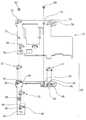
たとえば、シムユニット(50)は、シムベース(47)にシム(51)を取り付けた後、先に撮像素子ユニット(60)と組立状態にして、レンズ鏡筒(30)に配置することもできる。
この実施例として、図10に示すように、シムベース(47)に、2つの弾性変形可能なフック(41)を突設し、素子取付プレート(77)に前記フック(41)が係合可能な凹部(71)を形成する構成を例示できる。シムユニット(40)の位置決めを容易にするために、シムベース(47)に位置決め突起(42)(42)を突設し、素子取付プレート(77)には、前記位置決め突起(42)(42)が嵌まる位置決め孔(72)(72)を形成してもよい。For example, the shim unit (50) can be placed in the lens barrel (30) after the shim (51) is attached to the shim base (47) and then assembled with the image sensor unit (60).
In this embodiment, as shown in FIG. 10, two elastically deformable hooks (41) project from the shim base (47), and the hooks (41) can be engaged with the element mounting plate (77). A configuration for forming the recess (71) can be exemplified. In order to facilitate positioning of the shim unit (40), positioning protrusions (42) and (42) are projected from the shim base (47), and the element mounting plate (77) has the positioning protrusions (42) and (42). Positioning holes (72) and (72) into which can be fitted may be formed.
また、図11に示すように、シムユニット(40)には、ネジ孔(43)を形成し、素子取付プレート(77)にルーズ孔(73)を形成して、ネジ(83)止めにより、シムユニット(40)と撮像素子ユニット(60)を一体化しておくこともできる。 As shown in FIG. 11, a screw hole (43) is formed in the shim unit (40), a loose hole (73) is formed in the element mounting plate (77), and the screw (83) is fastened. The shim unit (40) and the image sensor unit (60) may be integrated.
上記のように、シムユニット(40)を撮像素子ユニット(60)と予め一体化しておくことで、シム(51)はシムベース(47)と素子取付プレート(77)に挟まれて脱落することはないから、これらの取り扱いをより容易にすることができる。 As described above, by integrating the shim unit (40) with the image sensor unit (60) in advance, the shim (51) can be dropped between the shim base (47) and the element mounting plate (77). Since there is no such thing, handling can be made easier.
また、シムベース(47)は、L字状に限定されず、コ字状、矩形孔を有する枠状など、種々選択可能である。 Further, the shim base (47) is not limited to an L shape, and can be variously selected such as a U shape or a frame shape having a rectangular hole.
使用するシム(50)の厚さや形状も、上記は一実施例であり、数値等は本発明で挙げたものに限定されるものではないことは勿論である。例えば、シム(50)を5種類以上用いたり、複数枚重ねて厚さ調整するようにしてもよい。 The thickness and shape of the shim (50) to be used are the above examples, and it goes without saying that the numerical values are not limited to those described in the present invention. For example, five or more types of shims (50) may be used, or a plurality of shims (50) may be stacked to adjust the thickness.
また、アオリ調整の手順として、レンズ鏡筒(17)と撮像素子ユニット(60)との間にシムユニット(40)を挟んで仮組立てを行なってからレンズ光軸Aに対する撮像面(61)の傾きを測定し、アオリ調整しながら再度組み立てることもできる。 Further, as a tilt adjustment procedure, after temporarily assembling the shim unit (40) between the lens barrel (17) and the imaging element unit (60), the imaging surface (61) of the lens optical axis A is arranged. It can be reassembled while measuring the tilt and adjusting the tilt.
本発明は、撮像素子とレンズ鏡筒とのアオリ調整を容易に行なうことのできるレンズユニット及びこれを具えた撮像装置として有用である。 INDUSTRIAL APPLICABILITY The present invention is useful as a lens unit that can easily adjust the tilt between the image pickup element and the lens barrel and an image pickup apparatus including the lens unit.
(10) デジタルカメラ(撮像装置)
(20) レンズユニット
(30) レンズ鏡筒
(33) 撮像窓
(40) シムユニット
(47) シムベース
(51) シム
(60) 撮像素子ユニット
(62) 撮像素子
(77) 素子取付プレート
(84) ネジ(10) Digital camera (imaging device)
(20) Lens unit
(30) Lens barrel
(33) Imaging window
(40) Shim unit
(47) Shim Base
(51) Sim
(60) Image sensor unit
(62) Image sensor
(77) Element mounting plate
(84) Screw
Claims (4)
Translated fromJapanese撮像素子と、一方の面に撮像素子が装着された素子取付プレートを具える撮像素子ユニットと、を具え、
前記撮像窓と前記撮像素子が対向するように、前記レンズ鏡筒に前記撮像素子ユニットを複数のネジにより取り付けてなるレンズユニットであって、
前記レンズ鏡筒と前記素子取付プレートとの間には、前記撮像窓の周縁に取り付けられ、前記撮像窓の少なくとも2辺に沿う形状を有するシムベースと、該シムベースの1又は複数箇所に夫々1又は複数装着されるシムからなり、シムを載置した状態で前記レンズ鏡筒あるいは前記素子取付プレートからシムユニットのみ取り外し可能なシムユニットが配備され、
前記レンズ鏡筒の前記撮像窓の周縁に設けられたユニット取付面には前記ネジの取り付け位置と異なる位置にガイドが突設されており、前記シムベースには、前記ガイドと対向する位置に前記ガイドに嵌まる第1のガイド孔が開設されており、前記素子取付プレートには、前記ガイドと対向する位置に前記ガイドに嵌まる第2のガイド孔が開設されていることを特徴とするレンズユニット。A lens barrel that houses a lens and has a rectangular imaging window through which the optical axis passes;
An image sensor, and an image sensor unit comprising an element mounting plate having the image sensor mounted on one surface thereof,
A lens unit in which the imaging element unit is attached to the lens barrel with a plurality of screws so that the imaging window and the imaging element face each other;
Between the lens barrel and the element mounting plate, a shim base that is attached to the periphery of the imaging window and has a shape along at least two sides of the imaging window, and one or more portions of the shim base, respectively, Ashim unit comprising a plurality of mountedshims, in whichonly theshim unitis removable from the lens barrel or the element mounting plate in a state where the shim is placed, is provided.
On the unit mounting surface provided at the periphery of the imaging window of the lens barrel, a guide protrudes at a position different from the mounting position of the screw, and the guide is provided on the shim base at a position facing the guide. The lens unit is characterized in that a first guide hole that fits into the guide is formed, and a second guide hole that fits into the guide is formed in the element mounting plate at a position facing the guide. .
4. The lens unit according to claim 3, wherein the positioning mechanism includes a positioning protrusion protruding from the shim base and a positioning hole that is opened in the shim and fits into the positioning protrusion.
Priority Applications (3)
| Application Number | Priority Date | Filing Date | Title |
|---|---|---|---|
| JP2012165849AJP6199014B2 (en) | 2012-07-26 | 2012-07-26 | Lens unit and image pickup apparatus having the same |
| US14/417,001US9407800B2 (en) | 2012-07-26 | 2013-07-22 | Lens unit and image pickup device including same |
| PCT/JP2013/069796WO2014017437A1 (en) | 2012-07-26 | 2013-07-22 | Lens unit and image pickup device including same |
Applications Claiming Priority (1)
| Application Number | Priority Date | Filing Date | Title |
|---|---|---|---|
| JP2012165849AJP6199014B2 (en) | 2012-07-26 | 2012-07-26 | Lens unit and image pickup apparatus having the same |
Publications (2)
| Publication Number | Publication Date |
|---|---|
| JP2014026090A JP2014026090A (en) | 2014-02-06 |
| JP6199014B2true JP6199014B2 (en) | 2017-09-20 |
Family
ID=49997248
Family Applications (1)
| Application Number | Title | Priority Date | Filing Date |
|---|---|---|---|
| JP2012165849AExpired - Fee RelatedJP6199014B2 (en) | 2012-07-26 | 2012-07-26 | Lens unit and image pickup apparatus having the same |
Country Status (3)
| Country | Link |
|---|---|
| US (1) | US9407800B2 (en) |
| JP (1) | JP6199014B2 (en) |
| WO (1) | WO2014017437A1 (en) |
Families Citing this family (3)
| Publication number | Priority date | Publication date | Assignee | Title |
|---|---|---|---|---|
| DK2479267T3 (en) | 2006-12-21 | 2017-03-27 | Basf Enzymes Llc | Amylases and Glucoamylases, Nucleic Acids Encoding Them, and Methods for Preparing and Using Them |
| US9210306B1 (en)* | 2014-05-31 | 2015-12-08 | Apple Inc. | Method and system for a single frame camera module active alignment tilt correction |
| JP2017136512A (en)* | 2016-02-01 | 2017-08-10 | パナソニックIpマネジメント株式会社 | Liquid ejection device |
Family Cites Families (13)
| Publication number | Priority date | Publication date | Assignee | Title |
|---|---|---|---|---|
| US5731834A (en)* | 1995-06-07 | 1998-03-24 | Eastman Kodak Company | Replaceable CCD array and method of assembly |
| JPH09130652A (en)* | 1995-10-31 | 1997-05-16 | Victor Co Of Japan Ltd | Image pickup element mount structure for video camera |
| JP4311874B2 (en)* | 2000-12-07 | 2009-08-12 | パナソニック株式会社 | Camera with flange back adjustment mechanism |
| DE10344768B3 (en)* | 2003-09-26 | 2005-08-18 | Siemens Ag | Optical module with resilient element between lens holder and circuit carrier and optical system |
| JP2006301187A (en)* | 2005-04-19 | 2006-11-02 | Canon Inc | Zoom lens retractable lens barrel |
| JP5079483B2 (en)* | 2007-12-14 | 2012-11-21 | 興和株式会社 | Image sensor unit and image sensor unit frame |
| JP4802221B2 (en)* | 2008-06-26 | 2011-10-26 | 東芝テリー株式会社 | Area image sensor support device and tilt adjustment method of the sensor |
| JP4943413B2 (en)* | 2008-12-24 | 2012-05-30 | 東芝テリー株式会社 | Camera assembly structure |
| JP5381404B2 (en)* | 2009-06-30 | 2014-01-08 | 株式会社ニコン | Lens barrel |
| JP2011154105A (en) | 2010-01-26 | 2011-08-11 | Renesas Electronics Corp | Liquid crystal display device and bias current adjusting method |
| JP2011188254A (en) | 2010-03-09 | 2011-09-22 | Hoya Corp | Movement adjustment mechanism for imaging device |
| JP2011237594A (en)* | 2010-05-10 | 2011-11-24 | Sony Corp | Lens barrel and imaging apparatus |
| US9661235B2 (en)* | 2012-04-13 | 2017-05-23 | Blackmagic Design Pty Ltd. | Camera having a separate image capture module and a method of assembling the camera |
- 2012
- 2012-07-26JPJP2012165849Apatent/JP6199014B2/ennot_activeExpired - Fee Related
- 2013
- 2013-07-22USUS14/417,001patent/US9407800B2/ennot_activeExpired - Fee Related
- 2013-07-22WOPCT/JP2013/069796patent/WO2014017437A1/enactiveApplication Filing
Also Published As
| Publication number | Publication date |
|---|---|
| WO2014017437A1 (en) | 2014-01-30 |
| JP2014026090A (en) | 2014-02-06 |
| US9407800B2 (en) | 2016-08-02 |
| US20150207969A1 (en) | 2015-07-23 |
Similar Documents
| Publication | Publication Date | Title |
|---|---|---|
| TWI625557B (en) | Annular optical element, imaging lens module and electronic device | |
| CN103597394B (en) | Lens barrel, photographing device, and control method for lens barrel | |
| US7929041B2 (en) | Image pickup device | |
| US7544004B2 (en) | Lens barrel and image pickup apparatus | |
| US7924513B2 (en) | Lens barrel | |
| JP5463651B2 (en) | Camera, camera accessories | |
| JP6199014B2 (en) | Lens unit and image pickup apparatus having the same | |
| JP2014026091A (en) | Tilt adjusting method for lens unit | |
| EP2574037A1 (en) | Image pickup apparatus having imaging sensor package | |
| CN108632586A (en) | Projecting apparatus system | |
| JP5418458B2 (en) | Method for adjusting optical displacement sensor, method for manufacturing optical displacement sensor, and optical displacement sensor | |
| CN113597575B (en) | lens unit | |
| US10061099B2 (en) | Lens device, imaging apparatus, and method of detecting position of movable lens | |
| US7990627B2 (en) | Lens device | |
| JP6062196B2 (en) | Lens unit and image pickup apparatus having the same | |
| JP2015176018A (en) | Lens device and imaging device including the same | |
| JP2010197816A (en) | Camera module | |
| WO2021149654A1 (en) | Optical vibration-proof device, optical device, and magnetic sensor fixing method | |
| JP6234089B2 (en) | Lens barrel and imaging device | |
| US11454866B2 (en) | Electronic rangefinder | |
| JP2013033166A (en) | Rotation angle detector for rotational polarization filter, and imaging device equipped therewith | |
| US10291903B2 (en) | Stereo camera | |
| JP6230305B2 (en) | Lens apparatus and imaging apparatus having the same | |
| JP2006208928A (en) | Plastic lens, lens unit, and assembling method of lens unit | |
| JP2018072403A (en) | Lens barrel and imaging device. |
Legal Events
| Date | Code | Title | Description |
|---|---|---|---|
| A621 | Written request for application examination | Free format text:JAPANESE INTERMEDIATE CODE: A621 Effective date:20150616 | |
| A131 | Notification of reasons for refusal | Free format text:JAPANESE INTERMEDIATE CODE: A131 Effective date:20160419 | |
| A521 | Request for written amendment filed | Free format text:JAPANESE INTERMEDIATE CODE: A523 Effective date:20160617 | |
| A131 | Notification of reasons for refusal | Free format text:JAPANESE INTERMEDIATE CODE: A131 Effective date:20160719 | |
| A521 | Request for written amendment filed | Free format text:JAPANESE INTERMEDIATE CODE: A523 Effective date:20160916 | |
| A131 | Notification of reasons for refusal | Free format text:JAPANESE INTERMEDIATE CODE: A131 Effective date:20170110 | |
| A521 | Request for written amendment filed | Free format text:JAPANESE INTERMEDIATE CODE: A523 Effective date:20170303 | |
| TRDD | Decision of grant or rejection written | ||
| A01 | Written decision to grant a patent or to grant a registration (utility model) | Free format text:JAPANESE INTERMEDIATE CODE: A01 Effective date:20170808 | |
| A61 | First payment of annual fees (during grant procedure) | Free format text:JAPANESE INTERMEDIATE CODE: A61 Effective date:20170823 | |
| R150 | Certificate of patent or registration of utility model | Ref document number:6199014 Country of ref document:JP Free format text:JAPANESE INTERMEDIATE CODE: R150 | |
| R250 | Receipt of annual fees | Free format text:JAPANESE INTERMEDIATE CODE: R250 | |
| R250 | Receipt of annual fees | Free format text:JAPANESE INTERMEDIATE CODE: R250 | |
| LAPS | Cancellation because of no payment of annual fees |