JP6196861B2 - Mobile battery - Google Patents
Mobile batteryDownload PDFInfo
- Publication number
- JP6196861B2 JP6196861B2JP2013195236AJP2013195236AJP6196861B2JP 6196861 B2JP6196861 B2JP 6196861B2JP 2013195236 AJP2013195236 AJP 2013195236AJP 2013195236 AJP2013195236 AJP 2013195236AJP 6196861 B2JP6196861 B2JP 6196861B2
- Authority
- JP
- Japan
- Prior art keywords
- power
- coil
- power transmission
- secondary battery
- battery
- Prior art date
- Legal status (The legal status is an assumption and is not a legal conclusion. Google has not performed a legal analysis and makes no representation as to the accuracy of the status listed.)
- Active
Links
Images


Landscapes
- Charge And Discharge Circuits For Batteries Or The Like (AREA)
Description
Translated fromJapanese本発明は、無接点給電に対応する機器に無接点で給電するとともに自身に無接点で充電可能なモバイルバッテリに関する。 The present invention relates to a mobile battery that can supply power to a device that supports contactless power supply in a contactless manner and can be charged in a contactless manner.
一般にワイヤレス給電(無接点給電)が知られている。ワイヤレス給電の方式の1つとして、1次コイル(送電用コイル)と2次コイル(受電用コイル)との間で磁束を介して電磁誘導により送電と受電とを行う電磁誘導方式が知られている(例えば、特許文献1参照)。電磁誘導方式によるワイヤレス給電は、比較的古くから行われていたが、近年、ワイヤレス給電の国際標準規格としてQi(登録商標)が設定された。
このQiの規格に基づく同一の規格ならば、基本的にいずれの給電装置と、いずれの受電装置とでもワイヤレス給電が可能になる。Generally, wireless power feeding (contactless power feeding) is known. As one of the methods of wireless power feeding, there is known an electromagnetic induction method for performing power transmission and reception by electromagnetic induction between a primary coil (power transmission coil) and a secondary coil (power reception coil) via magnetic flux. (For example, refer to Patent Document 1). Wireless power feeding by the electromagnetic induction method has been performed for a relatively long time, but in recent years, Qi (registered trademark) has been set as an international standard for wireless power feeding.
If the same standard based on the Qi standard is used, wireless power feeding can be basically performed by any power feeding device and any power receiving device.
ワイヤレス給電に対応した携帯機器として例えば一部のスマートフォン(以下、スマホと省略する)が知られている。給電装置の1次コイルに携帯機器の2次コイルの位置を合わせて近接させること、たとえば、給電装置上の所定範囲内に携帯機器を置くことにより、配線を接続することなく、携帯機器に給電して携帯機器の2次電池に充電を行うことが可能になっている。 For example, some smartphones (hereinafter abbreviated as smartphones) are known as portable devices that support wireless power feeding. Power is supplied to the mobile device without connecting the wiring by positioning the secondary coil of the mobile device close to the primary coil of the power supply device, for example, by placing the mobile device within a predetermined range on the power supply device. Thus, the secondary battery of the portable device can be charged.
また、給電装置は、電源コードにより、例えば、家庭のコンセント(商用電源)から電力を供給され、1次コイルに電流を流すようになっている。この際には、例えば、交流電源の周波数を上述の規格で定める所定範囲の周波数まで高めるようになっている。
また、携帯機器として、スマホやタブレットが使用されることが多くなっており、これらスマホや、タブレットでは、ワイヤレス給電に対応するものが増える傾向にある。Further, the power supply device is supplied with electric power from a household outlet (commercial power supply), for example, by a power cord, and causes a current to flow through the primary coil. In this case, for example, the frequency of the AC power supply is increased to a frequency within a predetermined range determined by the above-mentioned standard.
In addition, smartphones and tablets are frequently used as portable devices, and these smartphones and tablets tend to increase in number corresponding to wireless power feeding.
また、スマホやタブレットを比較的長時間使用し続けると内蔵する充電池(2次電池)の容量が足りなくなる。したがって、例えば、スマホ等を夜間フル充電しても次の夜間の充電開始可能な時間となる前に充電池を使い切り、電源が落ちてしまう場合がある。 In addition, if the smartphone or tablet is used for a relatively long time, the capacity of the built-in rechargeable battery (secondary battery) becomes insufficient. Therefore, for example, even if the smartphone or the like is fully charged at night, the rechargeable battery may be used up and the power may be turned off before the next night charging can be started.
そこで、スマホ等とともにモバイルバッテリ(携帯型2次電池内蔵電源)を携帯し、スマホ等の充電量が減少した際に、スマホ等をモバイルバッテリで充電することが行われている。 Therefore, a mobile battery (portable secondary battery built-in power source) is carried with a smartphone or the like, and the smartphone or the like is charged with the mobile battery when the charge amount of the smartphone or the like decreases.
モバイルバッテリは、2次電池を内蔵するとともに充電用回路を備え、例えば、外部電源から内部の2次電池に充電が可能で、かつ、モバイルバッテリの2次電池を電源としてスマホの2次電池に充電が可能になっている。このようなモバイルバッテリでは、内部2次電池の充電と、スマホ等の外部の2次電池内蔵機器の充電とを同時に行うことが一般的に可能である。 The mobile battery has a built-in secondary battery and a charging circuit. For example, the internal secondary battery can be charged from an external power source, and the mobile battery secondary battery is used as a power source for the smartphone secondary battery. Charging is possible. In such a mobile battery, it is generally possible to charge an internal secondary battery and charge an external secondary battery built-in device such as a smartphone at the same time.
また、モバイルバッテリの制御回路においては、外部電源から電力が共有されている状態、すなわち内部2次電池が充電可能な状態で外部2次電池が接続された場合に、外部2次電池を先に充電し、外部2次電池の充電が行われた後に、内部2次電池の充電を行うように制御することが提案されている(例えば、特許文献2参照)。 In the mobile battery control circuit, when the external secondary battery is connected in a state where the electric power is shared from the external power source, that is, the internal secondary battery can be charged, the external secondary battery is first connected. It has been proposed to control the internal secondary battery to be charged after charging and charging of the external secondary battery (see, for example, Patent Document 2).
この場合に、外部2次電池の充電から内部2次電池への充電の切り替えは、以下のタイミングで行われる。
すなわち、AC/DC変換回路を有するモバイルバッテリを用い、かつ、外部機器の外部2次電池(外部機器に内蔵される2次電池)の充電回路で定電流−定電圧充電制御が行われる場合に、外部機器において、定電流充電制御から定電圧充電制御に切り替わった際に、モバイルバッテリのAC/DC変換回路における出力電圧が高くなる。このタイミングまたは、出力電圧が高くなってから所定時間後のタイミングで、外部2次電池への充電から内部2次電池への充電に切り替わるようになっている。In this case, switching from charging of the external secondary battery to charging of the internal secondary battery is performed at the following timing.
That is, when a mobile battery having an AC / DC conversion circuit is used and constant current-constant voltage charging control is performed in a charging circuit of an external secondary battery (secondary battery built in the external device) of an external device. When an external device switches from constant current charge control to constant voltage charge control, the output voltage in the AC / DC conversion circuit of the mobile battery increases. At this timing or at a predetermined time after the output voltage has increased, the charging to the external secondary battery is switched to the charging to the internal secondary battery.
また、モバイルバッテリには、上述のワイヤレス給電の規格に対応することにより、内部2次電池のワイヤレス充電が可能なものが知られている。
このようなモバイルバッテリには、無接点給電装置(充電ステーション)を用いることにより、内蔵されている2次電池にワイヤレス充電を可能とする受電用コイルと、モバイルバッテリに内蔵されている充電池を有線(ワイヤード)で充電するための受電用接続端子と、配線を介して、外部機器を充電するための給電用接続端子と、上述のワイヤレスまたはワイヤードで供給された電力で内部の2次電池を充電するための充電制御回路とを備えている。In addition, there is known a mobile battery capable of wirelessly charging an internal secondary battery by complying with the above-described wireless power supply standard.
In such a mobile battery, by using a non-contact power supply device (charging station), a power receiving coil that enables wireless charging of a built-in secondary battery and a rechargeable battery built in the mobile battery are provided. A power receiving connection terminal for charging by wire (wired), a power connection terminal for charging an external device via the wiring, and an internal secondary battery with the power supplied wirelessly or wiredly as described above A charge control circuit for charging.
したがって、モバイルバッテリは、内蔵する充電池をワイヤレスでもワイヤードでも充電可能となっている。
なお、上述の無接点給電の国際標準規格においては、1次コイルおよび2次コイルをアンテナとして用いて微弱電波による近距離無線通信を行うことにより、送電側機器と受電側機器とでネゴシエーションを行い、ネゴシエーションが成立した場合にワイヤレス給電が行われるようになっている。Therefore, the mobile battery can charge the built-in rechargeable battery either wirelessly or wiredly.
In the above-mentioned international standard for contactless power feeding, the short-range wireless communication using weak radio waves is performed using the primary coil and the secondary coil as antennas, so that the power transmission side device and the power reception side device negotiate. When the negotiation is established, wireless power feeding is performed.
したがって、規格外のコイルや金属板等に対して送電用コイルの磁束(交番磁界)を当てるようなことがないようになっている。また、この近距離無線通信により受電側の機器の2次電池が満充電(所定の出力電圧)となった際に受電側の機器から送電側の機器に満充電を示す通知を行うようなことが可能である。例えば、充電される外部機器側では、上述の定電流−定電圧充電制御を行う場合に、定電流制御から定電圧制御に切り替えられた後に、充電の電流値が下がっていくので、設定された電流値以下となったことに基づいて満充電を検知することができる。 Therefore, the magnetic flux (alternating magnetic field) of the power transmission coil is not applied to non-standard coils or metal plates. In addition, when the secondary battery of the power receiving device is fully charged (predetermined output voltage) by this short-range wireless communication, a notification indicating full charging is sent from the power receiving device to the power transmitting device. Is possible. For example, when the above-described constant current-constant voltage charge control is performed on the external device side to be charged, the charge current value decreases after switching from constant current control to constant voltage control. Full charge can be detected based on the current value being less than or equal to the current value.
また、電磁誘導方式による給電では、送電用コイルと受電用コイルとが略同軸上に配置されるとともに近接していることが必要であり、位置がずれたり距離が離れたり、向きが異なったりすると送電の効率が著しく悪化する。
そこで、上述の規格では、例えば、送電用コイルをX−Y方向に移動可能とすることにより、受電用コイルに対して送電用コイルの位置合わせ可能にしたり、複数の送電用コイルを互いに一部だけ重なり合うように近接して配置し、受電用コイルに最も近い送電用コイルを選択して、選択された送電用コイルに電流を流すようにしたり、磁石を用いて位置合わせを可能したりするようになっている。In addition, in the power supply by the electromagnetic induction method, it is necessary that the power transmission coil and the power reception coil are arranged substantially coaxially and close to each other, and if the position is shifted, the distance is increased, or the direction is different. The efficiency of power transmission is significantly deteriorated.
Therefore, in the above-described standard, for example, by allowing the power transmission coil to move in the X-Y direction, the power transmission coil can be aligned with the power reception coil, or a plurality of power transmission coils are partially connected to each other. So as to overlap each other, select the power transmission coil closest to the power reception coil, and let the current flow through the selected power transmission coil, or use a magnet to align It has become.
ところで、例えば、スマホに内蔵されている2次電池の容量に対してモバイルバッテリの容量は、1〜4倍程度となっているのが一般的である。この場合に、スマホを毎日夜間に充電するものとした場合に、モバイルバッテリは、その容量や使い方によって、例えば、スマホと同様に毎日充電したり、1日置きから5日置きに充電したり、週に一回充電したりすることになる。 By the way, for example, the capacity of a mobile battery is generally about 1 to 4 times the capacity of a secondary battery built in a smartphone. In this case, if the smartphone is to be charged at night every day, the mobile battery can be charged daily, for example, like a smartphone, or every other day to every 5 days, depending on its capacity and usage. It will be charged once a week.
この場合に、モバイルバッテリがワイヤレス充電可能ならば、使い勝手を考えると、無接点給電装置を使ってワイヤレスで充電を行うことが好ましい。
この場合に、無接点給電装置が1つしかなく、かつ、スマホとモバイルバッテリを夜間に充電するものとすると、モバイルバッテリを充電する日は、スマホと充電が重なってしまいワイヤレス充電できるのはどちらか一方となり、他方はワイヤード充電で充電する必要がある。In this case, if the mobile battery can be charged wirelessly, it is preferable to charge wirelessly using a non-contact power supply device in consideration of usability.
In this case, if there is only one non-contact power feeding device and the smartphone and mobile battery are charged at night, on the day when the mobile battery is charged, which will overlap with the smartphone and can be charged wirelessly? It becomes one, and the other needs to be charged by wired charging.
特に、モバイルバッテリの2次電池の容量が大きいとワイヤレス充電に時間がかかり、モバイルバッテリが無接点給電装置を場所および時間の両方で専有してしまうことになる。 In particular, when the capacity of the secondary battery of the mobile battery is large, wireless charging takes time, and the mobile battery occupies the non-contact power supply device both in place and time.
また、無接点給電装置は、一度に一個の機器の充電を行う構成となっているものが多く、複数の充電が可能だとしてもせいぜい2個であり、例えば、スマホ、タブレット、モバイル無線ルータ、モバイルバッテリ、キーボードやヘッドセット等のBluetooth(登録商標)機器等の複数の機器を利用している場合に、全て無接点充電に対応するようになると、基本的に同時に複数の機器をワイヤレス充電するには、複数台の無接点給電装置を設置する必要がある。 In addition, many non-contact power supply devices are configured to charge one device at a time, and even if multiple charging is possible, there are at most two, for example, smartphones, tablets, mobile wireless routers, When using multiple devices such as mobile batteries, Bluetooth (registered trademark) devices such as keyboards and headsets, all of them are wirelessly charged at the same time if all of them support contactless charging. Needs to install a plurality of non-contact power feeding devices.
また、モバイルバッテリは、基本的に家の外に持ち出して使うので、実際に充電する際は屋内に置かれるとしても、移動中に濡れてしまう虞があり、防水性能があった方が好ましい。しかし、外部機器の充電をワイヤードで行うために接続端子を設けると、防水性能を持たせるのにコストがかかったり、各接続端子を閉塞するキャップ等を設けたりする必要がある。 In addition, since the mobile battery is basically taken out of the house and used, even if the mobile battery is actually charged, there is a possibility that the mobile battery may get wet during the movement, and it is preferable that the battery is waterproof. However, if a connection terminal is provided in order to charge an external device in a wired manner, it is necessary to provide a waterproof performance, and it is necessary to provide a cap or the like that closes each connection terminal.
本発明は、上記事情に鑑みてなされたものであり、ワイヤレス給電により1台の無接点給電装置上にスマホ等のワイヤレス給電に対応する機器と重ねて同時充電を可能にするモバイルバッテリを提供することを目的とする。 The present invention has been made in view of the above circumstances, and provides a mobile battery that enables simultaneous charging on a single non-contact power supply device by wireless power supply over a device such as a smartphone that supports wireless power supply. For the purpose.
本発明のモバイルバッテリは、
充放電可能な2次電池と、
電磁誘導による受電のための受電用コイルと、
電磁誘導による送電のための送電用コイルと、
前記受電用コイルで受電した交流を直流に変換して前記2次電池を充電する受電手段と、
前記2次電池から出力される直流を電磁誘導のための交流に変換して前記送電用コイルに供給するための送電手段とを備えることを特徴とする。The mobile battery of the present invention is
A rechargeable secondary battery;
A power receiving coil for receiving power by electromagnetic induction;
A coil for power transmission for power transmission by electromagnetic induction;
Power receiving means for charging the secondary battery by converting alternating current received by the power receiving coil into direct current;
Power transmission means for converting a direct current output from the secondary battery into an alternating current for electromagnetic induction andsupplying the alternating current to the power transmission coil.
このような構成によれば、受電用コイルと、受電手段とを備えることにより、外部の無接点給電装置を用いて、内部の充電池を無接点充電することができ、かつ、送電用コイルと、送電手段とを備えることにより、外部の無接点給電対応の機器に2次電池に充電された電力を用いて無接点給電することができる。
すなわち、このモバイルバッテリでは、内部の充電池の充電も外部の機器の充電も無接点で行うことができる。According to such a configuration, by including the power receiving coil and the power receiving means, the internal rechargeable battery can be contactlessly charged using the external non-contact power feeding device, and the power transmitting coil and By providing the power transmission means, it is possible to perform non-contact power supply using the power charged in the secondary battery to an external non-contact power supply compatible device.
That is, in this mobile battery, charging of an internal rechargeable battery and charging of an external device can be performed without contact.
したがって、モバイルバッテリでは、有線(ワイヤード)による受電および送電の必要がなく、受電や送電のためのケーブルを接続する接続端子を設けない構成とすることができる。これにより、ケーシング(ボディ)として、穴や開口部のない密閉容器状のものが使用可能になる。したがって、容易に防水性を付加できるとともに、あまりコストをかけずに防水性能を高めることができる。 Therefore, the mobile battery does not require wired power reception and power transmission, and can be configured without a connection terminal for connecting a cable for power reception or power transmission. As a result, the casing (body) can be a sealed container having no holes or openings. Accordingly, waterproofness can be easily added, and waterproof performance can be enhanced without much cost.
なお、接続端子用の穴や開口部をなくすことは可能であるが、2次電池を交換可能とする場合に、2次電池を出し入れ可能とするための開閉する開口部が必要となるが、2次電池の交換は、一般的に一年以上の長いサイクルで行われるので、開口部の開閉構造として開閉が比較的難しい構造としても問題が生じ難く、密閉性の高い開閉構造を用いることが可能である。また、このモバイルバッテリとは、携帯用の2次電池に自身の充電と外部機器の充電の機能を付加したものであり、基本的に内蔵される充電池がメインの部品となり、充電池の寿命が切れた場合に、製品としての寿命が切れるものとして、電池を交換できない構造としてもよく、この場合に防水性能をより高くすることができる。なお、組立時にケーシング内に各種部品を設置する必要があるので、ケーシングを1つの分品からなる構造とすることは難しいが、溶着や接着により接合するなどして一体化可能である。 Although it is possible to eliminate the holes and openings for the connection terminals, when the secondary battery can be replaced, an opening for opening and closing the secondary battery is required. Since the replacement of the secondary battery is generally performed in a long cycle of one year or more, it is difficult to cause a problem even if the opening / closing structure is relatively difficult to open / close. Is possible. In addition, this mobile battery is a portable secondary battery with its own charging and external device charging functions. The built-in rechargeable battery is the main component, and the life of the rechargeable battery If the battery expires, the product life may expire, and the battery may not be replaced. In this case, the waterproof performance can be further improved. In addition, since it is necessary to install various parts in a casing at the time of an assembly, it is difficult to make a structure which consists of one part of a casing, but it can integrate by joining by welding or adhesion | attachment.
また、外部の無接点給電装置により、内蔵の2次電池を充電している状態で、かつ、内蔵の2次電池の電力により、外部の無接点充電対応機器を充電することができる。すなわち、1つの無接点給電装置により、本発明のモバイルバッテリと、無接点充電対応機器との両方を同時に充電することができる。この場合に、無接点給電装置(据え置き型の充電ステーション)の上に本発明のモバイルバッテリを置き、その上に無接点充電対応のスマホ等の機器を置いて、充電を行うことになる。 In addition, an external contactless power supply device can charge an external contactless charging compatible device in a state where the internal secondary battery is charged and with the power of the internal secondary battery. That is, it is possible to simultaneously charge both the mobile battery of the present invention and the non-contact charging compatible device with one non-contact power feeding device. In this case, charging is performed by placing the mobile battery of the present invention on a non-contact power supply device (stationary charging station) and placing a device such as a smartphone that supports non-contact charging on the mobile battery.
したがって、モバイルバッテリとしてのモバイルバッテリの充電を必要とするタイミングと、スマホやタブレットの充電を必要とするタイミングとが重なっても、これらを同じ時期に1つの無接点給電装置(据え置き型)で、充電することが可能になる。なお、基本的に、給電側および受電側は、それぞれ、上述の無接点給電の国際標準規格に対応していることが好ましい。この場合に、国際標準規格に対応して、近距離無線通信によるネゴシエーションを可能とする通信装置や記憶装置や制御装置等を備えることが好ましい。 Therefore, even if the timing required to charge the mobile battery as a mobile battery overlaps with the timing required to charge the smartphone or tablet, these can be replaced with a single contactless power supply device (stationary type) at the same time. It becomes possible to charge. Basically, it is preferable that the power feeding side and the power receiving side respectively correspond to the above-described international standard for contactless power feeding. In this case, it is preferable to include a communication device, a storage device, a control device, and the like that enable negotiation by short-range wireless communication in accordance with the international standard.
本発明の前記構成において、前記受電手段を介して、前記受電用コイルを前記2次電池に繋ぐ受電経路と、
前記送電手段を介して、前記2次電池を前記送電用コイルに繋ぐ送電経路と、
前記受電用コイルと前記送電用コイルとを直接繋ぐ直結経路とを備え、
前記直結経路を切断して前記受電経路および前記送電経路の少なくとも一方を用いる第1経路状態と、前記受電経路および前記送電経路を切断して、前記直結経路を用いる第2経路状態とを切り替える経路切替手段を有することが好ましい。In the configuration of the present invention, a power receiving path that connects the power receiving coil to thesecondary battery via the power receiving means;
A power transmission path connecting thesecondary battery to the power transmission coil via the power transmission means;
A direct connection path directly connecting the power receiving coil and the power transmitting coil;
A path that switches between a first path state that uses at least one of the power reception path and the power transmission path by cutting the direct connection path, and a second path state that uses the direct connection path by cutting the power reception path and the power transmission path It is preferable to have a switching means.
このような構成によれば、スマホやタブレット等の無接点充電対応機器を急いで充電したい場合などに、モバイルバッテリと無接点充電対応機器とが同時に充電されるのではなく、スマホだけを充電することが考えらえる。この際に、無接点給電装置上に直接スマホを置いてしまうと、モバイルバッテリは、スマホの充電が終わっても充電されないことになる。 According to such a configuration, when you want to quickly charge a non-contact charging compatible device such as a smartphone or tablet, the mobile battery and the non-contact charging compatible device are not charged simultaneously, but only the smartphone is charged. I can think of that. At this time, if the smartphone is placed directly on the non-contact power feeding device, the mobile battery is not charged even after the smartphone has been charged.
そこで、モバイルバッテリにおいて、受電用コイルと受電手段の接続を解除するとともに、送電用コイルと送電手段の接続を解除し、受電用コイルと送電用コイルを直結することが考えられる。この場合に、受電用コイル側では無接点給電装置からの磁束に基づく電磁誘導により交流電流が生じ、この交流電流が送電用コイルに流れることにより、送電用コイルで磁束が生じ、無接点充電対応機器の受電用コイルで交流電流を生じさせることができる。 Therefore, in the mobile battery, it is conceivable that the connection between the power receiving coil and the power receiving means is canceled, the connection between the power transmitting coil and the power transmitting means is canceled, and the power receiving coil and the power transmitting coil are directly connected. In this case, on the power receiving coil side, an alternating current is generated by electromagnetic induction based on the magnetic flux from the non-contact power supply device, and this alternating current flows to the transmitting coil, thereby generating a magnetic flux in the transmitting coil and supporting contactless charging. An alternating current can be generated by the power receiving coil of the device.
これにより、無接点給電装置上にモバイルバッテリと、無接点充電対応機器を重ねておいた際に、モバイルバッテリは充電されず、無接点充電対応機器だけが充電される。なお、無接点充電対応機器が満充電となった際に、前記経路切替手段を第2経路状態から第1経路状態に戻し、受電用コイルと受電手段とを繋ぐ受電経路を接続した状態とするように制御されることが好ましい。 Thereby, when the mobile battery and the non-contact charging compatible device are stacked on the non-contact power supply device, the mobile battery is not charged, and only the non-contact charging compatible device is charged. When the contactless charging compatible device is fully charged, the path switching unit is returned from the second path state to the first path state, and the power receiving path connecting the power receiving coil and the power receiving means is connected. It is preferable to be controlled as described above.
また、本発明の前記構成において、前記受電用コイルと、外部の無接点給電装置に設けられた送電用コイルである外部送電用コイルとが結合可能となったことを検知する受電検知手段と、
前記送電用コイルと、外部の受電する機器に設けられた受電用コイルである外部受電用コイルとが結合可能となったことを検知する送電検知手段と、
前記受電検知手段が前記受電用コイルと前記外部送電用コイルとが結合可能なことを検知し、かつ、前記送電検知手段が前記送電用コイルと前記外部受電用コイルとが結合可能なことを検知したことに基づいて、前記経路切替手段が前記第1経路状態から前記第2経路状態に切り替えるように当該経路切替手段を制御する制御手段とを備えることが好ましい。Further, in the configuration of the present invention, a power reception detection means for detecting that the power reception coil and an external power transmission coil that is a power transmission coil provided in an external non-contact power supply device can be coupled,
A power transmission detecting means for detecting that the power transmission coil and an external power receiving coil that is a power receiving coil provided in an external power receiving device can be coupled;
The power reception detection means detects that the power reception coil and the external power transmission coil can be coupled, and the power transmission detection means detects that the power transmission coil and the external power reception coil can be coupled. Based on the above, it is preferable that the route switching unit includes a control unit that controls the route switching unit so as to switch from the first route state to the second route state.
このような構成によれば、無接点給電装置上に本発明のモバイルバッテリを置き、その上にスマホ等の無接点充電対応機器を置くことにより、それぞれの送電用コイルと受電用コイルの対で結合可能な状態となると、モバイルバッテリ内の受電用コイルと送電用コイルとが直結されることにより、モバイルバッテリの2次電池が充電されることなく無接点充電対応機器の2次電池だけが充電され、無接点充電対応機機器を早く充電することができる。 According to such a configuration, the mobile battery of the present invention is placed on the contactless power feeding device, and the contactless charging device such as a smartphone is placed on the mobile battery. When the connection is possible, the power receiving coil and the power transmitting coil in the mobile battery are directly connected, so that only the secondary battery of the contactless charging compatible device is charged without charging the secondary battery of the mobile battery. Therefore, it is possible to quickly charge a non-contact charging compatible device.
なお、無接点充電対応機器が満充電となった場合等において、無接点充電対応機器の充電が終了した場合に、経路切替手段が第1経路状態に戻すことが好ましい。この際には、送電経路を切断した状態で受電経路だけを接続するものとしてもよい。 Note that it is preferable that the path switching unit returns to the first path state when charging of the non-contact charging compatible apparatus is completed, such as when the non-contact charging compatible apparatus is fully charged. In this case, only the power reception path may be connected in a state where the power transmission path is disconnected.
また、本発明の前記構成において、前記2次電池の残量が所定残量以下となっていることを検知する所定残量検知手段を備え、
前記制御手段は、前記受電検知手段が前記受電用コイルと前記外部送電用コイルとが結合可能なことを検知し、かつ、前記送電検知手段が前記送電用コイルと前記外部受電用コイルとが結合可能なことを検知した際に、前記所定残量検知手段が前記2次電池の残量が所定残量以下となっていることを検知している場合に、前記経路切替手段が前記第1経路状態から前記第2経路状態に切り替えることなく前記第1経路状態に保持するように前記切替手段を制御し、前記所定残量検知手段が前記2次電池の残量が所定残量以下となっていることを検知していない場合に前記経路切替手段が前記第1経路状態から前記第2経路状態に切り替えるように前記経路切替手段を制御することが好ましい。In the above configuration of the present invention, the battery further comprises a predetermined remaining amount detecting means for detecting that the remaining amount of the secondary battery is equal to or less than a predetermined remaining amount,
The control unit detects that the power reception detection unit can couple the power reception coil and the external power transmission coil, and the power transmission detection unit couples the power transmission coil and the external power reception coil. When the predetermined remaining amount detecting means detects that the remaining amount of the secondary battery is equal to or less than a predetermined remaining amount when it is detected that the possibility is possible, the route switching means is the first route. The switching means is controlled so as to maintain the first path state without switching from the state to the second path state, and the predetermined remaining amount detecting means causes the remaining amount of the secondary battery to become less than the predetermined remaining amount. It is preferable to control the route switching unit so that the route switching unit switches from the first route state to the second route state when it is not detected that the route is present.
このような構成によれば、上述のようにモバイルバッテリの受電用コイルと送電用コイルを直結する際に、モバイルバッテリの蓄電量(電力の残量)が少なくなって設定された所定残量以下となった場合に、受電用コイルと送電用コイルを直結せずに、モバイルバッテリの2次電池に充電を行うことが可能になる。 According to such a configuration, when the power receiving coil and the power transmitting coil of the mobile battery are directly connected as described above, the storage amount (remaining amount of power) of the mobile battery is reduced and is equal to or less than the predetermined remaining amount set. In this case, the secondary battery of the mobile battery can be charged without directly connecting the power receiving coil and the power transmitting coil.
これによりモバイルバッテリで2次電池の過放電を防止するとともに、モバイルバッテリの制御手段等が電力低下により作動しなくなるのを防止できる。
上述の近距離無線通信や、その制御や、その他の制御等のためにモバイルバッテリは、起動時に電力を必要とするので、例えば、内部の2次電池が過放電とならないように制御することが好ましく、例えば、2次電池が過放電となる前に送電手段の動作を停止するなどの過放電防止用の制御を行うことが好ましい。なお、2次電池の残量が所定の残量になっているか否かの検知は、例えば、2次電池の電圧で測定するが、充電電流、放電電流の値等を用いる周知の方法で検知するものとしてもよい。As a result, it is possible to prevent the secondary battery from being overdischarged by the mobile battery and to prevent the mobile battery control means from operating due to power reduction.
The mobile battery requires power at the time of start-up for the above-mentioned short-range wireless communication, its control, and other controls. For example, the internal secondary battery can be controlled not to be overdischarged. Preferably, for example, it is preferable to perform control for preventing overdischarge such as stopping the operation of the power transmission means before the secondary battery becomes overdischarged. In addition, the detection of whether or not the remaining amount of the secondary battery is a predetermined remaining amount is, for example, measured by the voltage of the secondary battery, but is detected by a known method using the value of the charging current, the discharging current, etc. It is good also as what to do.
また、本発明の前記構成において、前記受電用コイルと、前記送電用コイルとが略同軸上に配置されていることが好ましい。 In the configuration of the present invention, it is preferable that the power reception coil and the power transmission coil are arranged substantially coaxially.
このような構成によれば、上述のように一つの無接点給電装置を用いて、本発明のモバイルバッテリと、無接点充電対応機器とを充電する場合に、受電用コイル内を通る磁束の中心と、送電用コイル内を通る磁束の中心とを合わせることができ、例えば、受電用コイルと送電用コイルとの間で磁束の漏れが生じる場合に、充電効率を高めることができる。 According to such a configuration, when the mobile battery of the present invention and the non-contact charging compatible device are charged using one non-contact power supply device as described above, the center of the magnetic flux passing through the power receiving coil. And the center of the magnetic flux passing through the inside of the power transmission coil. For example, when leakage of magnetic flux occurs between the power reception coil and the power transmission coil, the charging efficiency can be increased.
但し、この場合に、受電用コイル側と送電用コイル側とで、流れる交流電流が同期している必要がある。すなわち、受電用コイル側で受ける磁束の交番の位相と、送電用コイル側で発生する磁束の交番(交番磁界)の位相が同期していることが好ましい。これら磁束の交番の位相が大きくずれたり、逆になったりすると互いの磁束が打ち消し合い充電効率が低下する。
そこで、後述のように前記送電手段は、前記受電用コイルで受ける磁束の交番の位相に対して、前記送電用コイルから発生する磁束の交番の位相を合わせる同期手段を備えることが好ましい。この場合に、受電用コイルは、外部の無接点給電装置で発生する磁束を受けることになるので、受電用コイルで受ける磁束の交番の位相に合わせて送電用コイルで磁束を交番させることになる。However, in this case, the flowing alternating current needs to be synchronized between the power receiving coil side and the power transmitting coil side. That is, it is preferable that the phase of the alternating magnetic flux received on the power receiving coil side and the phase of the alternating magnetic flux generated on the power transmitting coil side (alternating magnetic field) are synchronized. If the alternating phases of these magnetic fluxes are greatly shifted or reversed, the mutual magnetic fluxes cancel each other and the charging efficiency decreases.
Therefore, as described later, it is preferable that the power transmission unit includes a synchronization unit that matches the phase of the alternating magnetic flux generated from the power transmission coil with the phase of the alternating magnetic flux received by the power receiving coil. In this case, the power receiving coil receives the magnetic flux generated by the external non-contact power feeding device, so that the magnetic flux is alternated by the power transmitting coil in accordance with the alternating phase of the magnetic flux received by the power receiving coil. .
また、上述のように受電用コイルと送電用コイルを直結して、外部の無接点給電装置から外部の無接点充電可能なスマホ等の機器を充電する場合も、同様に受電用コイルと送電用コイルを同軸上に配置することにより、充電効率を高めることができる。 In addition, when a power receiving coil and a power transmitting coil are directly connected as described above to charge a device such as an external non-contact chargeable smartphone from an external non-contact power supply device, the power receiving coil and the power transmitting coil are similarly used. Charging efficiency can be increased by arranging the coils on the same axis.
また、本発明の前記構成において、前記送電手段は、前記受電用コイルで受ける磁束の交番の位相に対して、前記送電用コイルから発生する磁束の交番の位相を合わせる同期手段を備えることが好ましい。 In the configuration of the present invention, it is preferable that the power transmission unit includes a synchronization unit that matches the phase of the alternating magnetic flux generated from the power transmission coil with the phase of the alternating magnetic flux received by the power receiving coil. .
このような構成によれば、上述のように受電用コイルで受ける磁束と、送電用コイルで発生する磁束とで、位相がずれたり逆転したりするのを防止でき、上述のように内部2次電池と外部2次電池を同時に充電する場合に、位相がずれることによって充電効率が低下するのを防止することができる。 According to such a configuration, it is possible to prevent the phase from being shifted or reversed between the magnetic flux received by the power receiving coil and the magnetic flux generated by the power transmitting coil as described above. When charging the battery and the external secondary battery at the same time, it is possible to prevent the charging efficiency from being lowered due to a phase shift.
また、本発明の前記構成において、前記受電用コイルと、外部の無接点給電装置に設けられた送電用コイルである外部送電用コイルとの位置合わせと、前記送電用コイルと、外部の受電する機器に設けられた受電用コイルである外部受電用コイルとの位置合わせに用いられる磁石を備え、
前記磁石の2種類の磁極のうちの一方の磁極が前記受電用コイル側の端部に配置され、他方の磁極が前記送電用コイル側の端部に配置され、
かつ、一方の磁極が前記外部の給電装置に設けられた位置合わせ用磁石の位置合わせに用いられる磁極と反対の磁極であることを特徴とする。Further, in the configuration of the present invention, the power receiving coil is aligned with an external power transmitting coil that is a power transmitting coil provided in an external non-contact power supply device, and the power transmitting coil receives power from the outside. A magnet used for alignment with an external power receiving coil that is a power receiving coil provided in the device,
One of the two types of magnetic poles of the magnet is disposed at the end on the power receiving coil side, and the other magnetic pole is disposed at the end on the power transmission coil side,
One of the magnetic poles is a magnetic pole opposite to the magnetic pole used for alignment of an alignment magnet provided in the external power supply device.
このような構成によれば、モバイルバッテリの無接点給電装置から電力の供給を受ける受電用コイルが有る側の面(ケースの側面)を無接点給電装置の磁石に近づけると、モバイルバッテリの磁石と無接点給電装置の磁石とが吸引し合うことにより、位置合わせが可能になるが、モバイルバッテリの送電用コイルがある側の面を無接点給電装置に近づけると、モバイルバッテリの磁石と無接点給電装置の磁石とが反発し合うことにより、位置合わせができず、無接点給電装置に対して、モバイルバッテリの給電側の側面と送電側の側面とを間違えてセットするのを防止することができる。 According to such a configuration, when the surface (side surface of the case) on which the power receiving coil that receives power supplied from the contactless power supply device of the mobile battery is brought close to the magnet of the contactless power supply device, Positioning is possible by attracting the magnet of the contactless power supply device to each other, but if the surface of the mobile battery where the power transmission coil is located is brought close to the contactless power supply device, the mobile battery magnet and the contactless power supply Since the magnets of the device repel each other, the alignment cannot be performed, and it is possible to prevent the side surface on the power feeding side and the side surface on the power transmission side of the mobile battery from being set incorrectly with respect to the contactless power feeding device. .
なお、本発明のモバイルバッテリでは、給電側と送電側とで二つの平面状の側面が必要であり、例えば、給電だけ無接点となる装置や、受電だけ無接点となる装置のように、一方の側面を凸面にするようなことができない。 The mobile battery of the present invention requires two planar side surfaces on the power supply side and the power transmission side. For example, a device that has no contact only for power supply or a device that has no contact only for power reception, The side cannot be made convex.
したがって、電磁誘導による受電と送電の両方が可能な本発明のモバイルバッテリでは、受電側の側面と、給電側の側面とをその形状により物理的に分けることが困難であるが、上述の磁石の磁極により、物理的に区別がつくことになり、無接点給電装置に送電用の面を当接してしまうのを磁石の反発力により防止できる。 Therefore, in the mobile battery of the present invention capable of both power reception and power transmission by electromagnetic induction, it is difficult to physically separate the power reception side surface and the power supply side surface according to the shape. The magnetic poles can be physically distinguished from each other, and the contact of the power transmission surface with the contactless power supply device can be prevented by the repulsive force of the magnet.
なお、無接点充電対応機器において、無接点給電装置の磁石に吸着される鉄等の部材ではなく、磁石を設けるようにすれば、モバイルバッテリの受電側の面に間違ってスマホ等の無接点充電対応機器を載せてしまうのを防止できる。 In addition, if a magnet is provided instead of a member such as iron that is attracted to the magnet of the contactless power supply device in a contactless charging compatible device, contactless charging of a smartphone or the like by mistake on the power receiving side of the mobile battery It is possible to prevent loading of compatible devices.
また、本発明の前記構成において、受電用コイルと、前記送電用コイルとが受電と送電との両方を行う一つの送受電用コイルとされ、
前記送受電用コイルに前記受電手段と、前記送電手段とを切り替えて接続可能にされるとともに、時分割により送電と受電とを繰り返し切り替えることにより、送電と受電を擬似的に同時に可能とする送受電時分割手段を備えることが好ましい。Further, in the configuration of the present invention, the power reception coil and the power transmission coil are one power transmission / reception coil that performs both power reception and power transmission,
The power receiving means and the power transmitting means can be switched and connected to the power transmitting / receiving coil, and transmission and power receiving can be simulated and simultaneously performed by repeatedly switching between power transmission and power reception by time division. It is preferable to provide power receiving time division means.
このような構成によれば、1つのコイルを受電用と送電用に切り替えて、無接点給電装置によるモバイルバッテリの無接点充電が可能で、かつ、モバイルバッテリによる無接点充電対応機器の無接点充電が可能になる。
また、無接点給電装置上にモバイルバッテリと無接点充電対応機器とを重ねて配置した場合に、モバイルバッテリと、無接点充電対応機器器との両方を擬似的に同時に充電することが可能になる。According to such a configuration, one coil can be switched between power reception and power transmission, and the contactless charging of the mobile battery by the contactless power supply device is possible, and the contactless charging of the contactless charging compatible device by the mobile battery is possible. Is possible.
Moreover, when a mobile battery and a non-contact charging compatible device are arranged on the non-contact power supply device, both the mobile battery and the non-contact charging compatible device can be simultaneously simulated in a pseudo manner. .
本発明のモバイルバッテリによれば、内蔵の2次電池の充電も、スマホ等の無接点充電対応機器の充電も無接点で行えるので、接続端子を必要とせず、容易に防水機能を付与できるとともに、低コストで防水性能を高めることができる。
また、コイルが1つであっても、内蔵の2次電池と、外部の無接点充電対応機器を無接点充電することが可能になる。According to the mobile battery of the present invention, the built-in secondary battery can be charged in a contactless charging device such as a smartphone without contact, so a connection terminal is not required and a waterproof function can be easily provided. Waterproof performance can be increased at low cost.
Further, even if there is only one coil, it is possible to charge the built-in secondary battery and the external contactless charging compatible device in a contactless manner.
以下、図面を参照しながら本発明の第1実施の形態について説明する。
この実施の形態のモバイルバッテリは、内部に2次電池を有する所謂モバイルバッテリであり、内部の2次電池の充電と、外部の無接点充電対応機器とをそれぞれ無接点充電可能となっている。Hereinafter, a first embodiment of the present invention will be described with reference to the drawings.
The mobile battery of this embodiment is a so-called mobile battery having a secondary battery inside, and can charge the internal secondary battery and the external contactless charging compatible device in a contactless manner.
また、この際の電磁誘導方式の送受電は、Qiの国際標準規格に対応しており、Qi対応の据置型(非携帯型)の無接点給電装置(以下充電ステーションと称する)を用いて内部の2次電池の無接点充電が可能で、Qi対応のスマホ等の無接点充電対応機器(以下、スマホと記載するがその他の無接点充電対応機器であってもよい)の無接点充電が可能になっている。 In addition, the electromagnetic induction type power transmission and reception at this time corresponds to the international standard of Qi, and uses a stationary (non-portable) non-contact power supply device (hereinafter referred to as a charging station) compatible with Qi. Can be contactlessly charged, and can be contactlessly charged for Qi-compatible smartphones and other non-contact charging compatible devices (hereinafter referred to as smartphones, but may be other non-contact charging compatible devices). It has become.
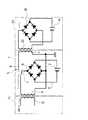
図1に示すように、このモバイルバッテリ1は、2次電池2と、受電用コイル3と、送電用コイル4と、これら2次電池2、受電用コイル3、送電用コイル4に接続されている充放電制御回路5とを備えている。 As shown in FIG. 1, the mobile battery 1 is connected to a
2次電池2は、たとえば、リチウムイオンバッテリであり、複数のセルからなっているとともに、例えば、受電用コイル3と送電用コイル4の間に配置されている。なお、リチウムバッテリは、複数セルではなく、1つのセルからなるものであってもよい。
受電用コイル3は、電磁誘導方式の無接点充電機(無接点給電装置)である充電ステーション11の外部1次コイルとしての外部送電用コイル12と結合する2次コイルとして機能し、充電ステーション11において送電用コイル12に所定周波数範囲の交流電流が流されることにより生じる交流磁界(磁束)により、交流電流を生じるコイルである。The
The
なお、充電ステーション11では、たとえば、家庭用交流電源からの交流電流を所定周波数の交流電流に変換して送電用コイル12に流すための充電ステーション11用の送電制御回路を備える。送電制御回路は、上述の近距離無線通信用の通信回路を備える。 The charging
送電用コイル4は、電次誘導方式の無接点充電対応機器としての例えばスマホ21の外部2次コイルとしての外部受電用コイル22と結合する1次コイルとして機能し、例えば、2次電池2から出力される直流電流を所定周波数の交流電流に変換して送電用コイル4に流すことにより、送電用コイル4で交番磁界が生じ、スマホ21の受電用コイル22で交流電流が生じる。 The
モバイルバッテリ1の充放電制御回路5は、例えば、ワンチップまたは複数チップからなるモジュールとして製造されるものであり、以下のような回路を備えるものとなっている。 The charge /
すなわち、充放電制御回路5は、MPUを備える制御回路と、受電用コイル3から入力する交流電流を直流電流に変換するAC/DC変換回路を有するとともに、変換された直流電流を充電用の電圧値及び電流値に変換して2次電池を充電するための受電回路(充電回路)と、2次電池から出力される直流を所定周波数の交流に変換して送電用コイル4に出力するDC/AC変換回路(インバータ)を有する。
さらに、充放電制御回路5は、送電用コイル4から交番磁界を発生させるための送電回路と、後述のように受電用コイル3で生じた交流電流を直接送電用コイル4に流すための切替スイッチ7(図2に図示)を備える経路切替手段と、Qiの規格で用いられる近距離無線通信用の通信回路を備える。なお、近距離無線の通信回路は、受電側と送電側とで同時に通信可能となっている必要がある。That is, the charge /
Further, the charge /
さらに、充放電制御回路5は、上述の充電回路の一部として、2次電池の過放電や過充電や過電流を防止するとともに、複数セルからなる2次電池2のセルバランスを取る保護回路を備える。なお、保護回路は、充放電制御回路5と別に設けるものとし、例えば、2次電池2側に設けてもよく、2次電池2のプラスおよびマイナス電極と、充放電制御回路5との間に配置される構成であればよい。 Furthermore, the charge /
また、充放電制御回路5は、2次電池2の定電流定電圧充電制御等の充電制御を行う充電制御回路を備える。
AC/DC変換回路は、例えば、図2に示すように4つのダイオードを備えるブリッジ型整流回路6を有するものである。なお、図2においては、ブリッジ型整流回路6から出力される直流電流により直接2次電池2を充電する構成であるが、実際には、上述の充電制御回路5および保護回路を介して2次電池2が充電される。なお、上述の各回路の制御は、例えば、上述の制御回路が行う。The charge /
The AC / DC conversion circuit has, for example, a bridge
スマホ21においては、図1に示すように受電用コイル22と2次電池24と、受電用コイル22で生じた交流電流を直流電流に変換するとともに上述の定電流定電圧充電制御等により2次電池24を充電する充電制御回路23が設けられている。なお、モバイルバッテリ1の充放電制御回路のAC/DC変換回路、受電回路(充電回路)、通信回路および制御回路が、スマホ21の充電制御回路23に相当する。 In the
また、スマホ21の充電制御回路23は、図2示すように、AC/DC変換回路の一部としてのブリッジ型整流回路5を備える。図2においても、ブリッジ型整流回路5から直接2次電池を充電する構成となっているが、充電制御回路23は、AC/DC変換回路の他に充電回路および保護回路を有し、充電回路および保護回路を介して2次電池24が充電される。 Further, as shown in FIG. 2, the charging
図2に示すように、モバイルバッテリ1の充放電制御回路5には、受電用コイル3で発生した交流電流を整流して2次電池を充電するための受電経路9と、2次電池の電力を用いて図示しないインバータを介して送電用コイル4に電流を供給するための送電経路(図示略)と、受電用コイル3で生じた電流を送電用コイル4に直接供給する直結経路8と、受電経路9と直結経路8とを切り替える切替スイッチ7とを備える。 As shown in FIG. 2, the charge /
なお、図2において、切替スイッチ7は、受電経路9と直結経路8とを切り返るように図示されているが、実際には、受電経路9と直結経路8との切り替えと、送電経路と直結経路8との切り替えを行うようになっている。すなわち、切替スイッチ7は、直結経路8を切断して、受電経路9と送電経路との両方または一方が接続された第1経路状態と、受電経路9と送電経路との両方が切断されて、直結経路8が接続された第2経路状態とを、切替スイッチ7により切り替えられるようになっている。 In FIG. 2, the change-over switch 7 is illustrated so as to switch back between the
また、切替スイッチ7は、例えば、スイッチング素子から構成され、充放電制御回路5の制御回路に制御されて、上述の第1経路状態と第2経路状態とを切り替えるようになっており、切替スイッチ7と充放電制御回路5によって、第1経路状態と第2経路状態とを切り替える経路切替手段が構成される。 The change-over switch 7 is constituted by, for example, a switching element, and is controlled by the control circuit of the charge /
なお、第1経路状態における受電経路および送電経路のオン・オフは、たとえば、通信回路による近距離無線通信により、モバイルバッテリ1の受電用コイル3と充電ステーション11の送電用コイル12とが、近接して結合可能な状態であると判定された場合に、受電経路を接続し、モバイルバッテリ1の送電用コイル4と、スマホ21の受電用コイル22とが、近接して結合可能な状態であると判定された場合に、送電経路を接続するようになっている。なお、受電用コイル3および送電用コイル4の両方が結合可能な場合には、受電経路9と送電経路との両方が接続されるか、第2経路状態に切り替えられる。 The power reception path and the power transmission path in the first path state are turned on / off by, for example, close proximity of the
ここで、上述の近距離無線通信を行う通信回路が、モバイルバッテリ1の受電用コイル3と、充電ステーション11の送電用コイル12とが結合可能となったことを検知する受電検知手段として機能するとともに、モバイルバッテリ1の送電用コイル4と、スマホ21の受電用コイル22とが結合可能となったことを検知する送電検知手段として機能することになる。 Here, the communication circuit that performs the short-range wireless communication functions as a power reception detection unit that detects that the
なお、受電経路9と送電経路との両方を接続するか、これらを接続せずに直結経路8を接続するかは、たとえば、設定により変更される。なお、モバイルバッテリ1の設定変更は、たとえば、モバイルバッテリ1に無線LAN等の通信機能を設けて、スマホ21等から無線通信により設定変更可能としてもよい。この場合にモバイルバッテリ1に設定変更用のスイッチ等を設ける必要がなく、防水機能を設ける場合にスイッチが防水機能の低下の原因となるのを防止できる。 Whether to connect both the
なお、第2経路状態として受電用コイル3と送電用コイル4とを直結すると、受電用コイル3で発生した電流が送電用コイル4に流れ、送電用コイル4において、交番磁界が生ずる。 When the
この場合に、充電ステーション11上にモバイルバッテリ1を載せ、さらに、モバイルバッテリ1上にスマホ21を載せた状態で、モバイルバッテリ1は、充電ステーション11の送電用コイル12で生じた交番磁界(磁束)を、スマホ21の受電用コイル22に仲介する状態となる。 In this case, when the mobile battery 1 is placed on the charging
ここで、上述のように充電ステーション11上に、充電ステーション11の送電用コイル12に受電用コイル3を対向させるようにモバイルバッテリ1を載せ、モバイルバッテリ1上にモバイルバッテリ1の送電用コイル4に受電用コイル22を対向させるようにスマホ21を載せた場合に、上述の第1経路状態では、充電ステーション11の送電用コイル12と、モバイルバッテリ1の受電用コイル3が結合し、モバイルバッテリ1の送電用コイル4とスマホ21の受電用コイル22が結合する。 Here, as described above, the mobile battery 1 is placed on the charging
この場合に、第1経路状態では、送電経路と受電経路とが接続され、受電経路9を介して充電ステーション11からの送電に基づいて、モバイルバッテリ1の2次電池2が充電され、送電経路を介して、モバイルバッテリ1の2次電池2からの電流に基づいて、スマホ21の2次電池24が充電されることになる。 In this case, in the first path state, the power transmission path and the power reception path are connected, and the
この場合に、充電ステーション11の上にスマホ21を載せて、直接スマホ21を充電する場合よりも、スマホ21の2次電池24の充電効率が低下する虞がある。
特に、モバイルバッテリ1の2次電池2の残量が少ない場合に、モバイルバッテリ1が充電ステーション11により充電されることにより、電力がモバイルバッテリ1の2次電池2の充電に使われてしまい、スマホ21の充電が遅くなる。In this case, the charging efficiency of the
In particular, when the remaining amount of the
それに対して、上述の第2経路状態で、直結経路8を接続した場合には、充電ステーションから受けた電流は、受電用コイル3からそのまま送電用コイル4に流れることになり、2次電池2の充電に使用されない。また、直流と交流との変換や電圧値や電流値の変換もないため、これら各種の変換におけるロスがなく、効率的にスマホ21を充電することができる。 On the other hand, when the
また、この場合に、モバイルバッテリ1は、充電可能に充電ステーション11上に載った状態なので、例えば、スマホ21が所定の充電量、例えば満充電となったことを示す近距離通信による通知があった場合に、充放電制御回路5の制御回路の制御により、第2経路状態から第1経路状態に切り替えて、モバイルバッテリ1の2次電池2の充電を開始することができる。すなわち、制御として、第2経路状態から第1経路状態に切り替えるだけで、自動的にスマホ21の充電からモバイルバッテリ1の充電に切り替えることができる。なお、スマホ21からモバイルバッテリ1への充電の切り替えは、スマホ21が満充電となった場合が好ましいが、満充電となる前の所定の充電量でモバイルバッテリ1に充電を切り替えるものとしてもよい。 In this case, since the mobile battery 1 is on the charging
第2経路状態から第1経路状態に切り替えた場合に、スマホ21の所定の充電量が満充電ならば、スマホ21への充電は行わずにモバイルバッテリ1の2次電池2の充電だけを行い、所定の充電量が満充電未満の場合には、上述のようにモバイルバッテリ1の2次電池2の充電と、スマホ21の2次電池24の充電との両方を行うようにしてもよい。この場合に、スマホ21が満充電となった際に、スマホ21の充電を停止し、モバイルバッテリ1が満充電となった際に、モバイルバッテリ1の充電を停止する。 If the predetermined charge amount of the
なお、モバイルバッテリ1の2次電池2では、スマホ21を充電することにより、急速に充電量が低下することになるが過放電となる前に、充放電制御回路5によりスマホ21への充電が停止され、過放電が防止される。しかし、2次電池2では、自己放電により徐々に充電量が低下することになる。 In the
したがって、モバイルバッテリ1の使用状態によっては、モバイルバッテリ1の2次電池2の過放電の防止や、モバイルバッテリ1の制御回路を含む充放電制御回路5の使用電力、特に起動電力の確保のために、2次電池2を早く充電することが好ましい場合がある。そこで、たとえば、モバイルバッテリ1の2次電池2の電圧が所定電圧(過放電となる電圧より少し高い電圧)以下の場合に、上述のように第1経路状態から第2経路状態に切り替えることなく、第1経路状態のまま、受電経路を接続状態とし、送電経路を切断状態とする。
これにより、残量が少ないモバイルバッテリ1の2次電池2を充電することができ、過放電の防止と、充放電制御回路5用の電力を確保することができる。Therefore, depending on the usage state of the mobile battery 1, it is possible to prevent overdischarge of the
Thereby, the
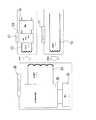
また、モバイルバッテリ1は、送受電に際して結合される外部の送電用コイル12と、内部の受電用コイル3の位置合わせと、外部の受電用コイル22と、内部の送電用コイル4との位置合わせ用の磁石10を備える。 In addition, the mobile battery 1 includes an external
この実施の形態では、受電用コイル3と導電用コイル4とが同軸上に配置されるとともに、受電用コイル3の中央部の空間と送電用コイル4の中央部の空間とを貫通するように位置決め用の棒状の磁石10が配置されているので、2次電池2は、その複数のセルが磁石を間に挟んで二つに分けて配置されている。なお、磁石10は一つである必要はなく、2つに分けられていてもよい。この場合に、受電用コイル3側に配置される磁石10の外部の充電ステーション11に載せられる側の面(底面)に向く磁極と、送電用コイル4側に配置される磁石の外部のスマホ21が置かれる面(天面)に向く磁極とが逆の磁極になっている必要がある。 In this embodiment, the
ここで、例えば、図3に示すように、充電ステーション11の磁石11は、N極がスマホ21やモバイルバッテリ1が載せられる天面に向いて配置されている。また、モバイルバッテリ1では、磁石10のN極をスマホ21等が載せられる天面に向け、S極を充電ステーション11の天面に載せられる底面に向けている。これにより、モバイルバッテリ1の受電側となる底面を充電ステーション11の天面に載せると、充電ステーション11の磁石13と、モバイルバッテリ1の磁石10が吸着することにより、位置合わせやそのアシストが可能になる。 Here, for example, as shown in FIG. 3, the
それに対して、充電ステーション11の天面にモバイルバッテリ1の送電側の天面を載せると、充電ステーション11の磁石13とモバイルバッテリ1の磁石10が反発し、モバイルバッテリ1の間違った面を充電ステーションに載せた場合に磁石10と磁石13の反発力により使用者が間違いに気づくことになる。
なお、磁極の配置が上述のようになっていれば、磁石10を2つに分けて配置してもよく、2つの磁石10の間に2次電池を2つに分けることなく配置することができる。On the other hand, when the top surface on the power transmission side of the mobile battery 1 is placed on the top surface of the charging
If the magnetic poles are arranged as described above, the
また、スマホ21の受電用コイル22には、磁石10に吸着される素材、例えば、鉄等を配置するが、図3に示すようにスマホ21にも磁石26を配置するものとしてもよい。この場合には、モバイルバッテリ1の充電ステーション11から受電する側の面に間違ってスマホ21を載せた場合に、磁石10と磁石26が反発することにより、使用者にスマホ21を間違った面に載せていることを気づかせることができる。なお、モバイルバッテリ1およびスマホ21に磁石10、26を配置する場合の磁極の向きは、充電ステーション11の天面を向く磁極を基準に決定され、この磁極と逆の磁極がスマホ21とモバイルバッテリ1の底面に向けて磁石10および磁石26が配置さる。さらに、モバイルバッテリ1のスマホ21を載せる天面に向けて充電ステーション11の天面を向く磁極と同じ磁極が配置される。 In addition, the
言い換えれば、ワイヤレス給電に対応する受電側と送電側の各機器において、送電側に配置される磁極がそれぞれ同じにされるとともに、受電側に配置される磁極がそれぞれ同じにされ、かつ、受電側と送電側とで磁極が逆になっていればよい。モバイルバッテリ1は、受電側と送電側との両方を有するので、受電側となる底面側に受電側の磁極が配置され、送電側となる天面側に送電側の磁極が配置される。 In other words, in each device on the power receiving side and power transmission side corresponding to wireless power feeding, the magnetic poles arranged on the power transmission side are made the same, and the magnetic poles arranged on the power receiving side are made the same, and the power receiving side It is sufficient that the magnetic poles are reversed on the power transmission side. Since the mobile battery 1 has both a power reception side and a power transmission side, the power reception side magnetic pole is disposed on the bottom surface side serving as the power reception side, and the power transmission side magnetic pole is disposed on the top surface side serving as the power transmission side.
ここでは、モバイルバッテリ1と、このモバイルバッテリ1に電力を供給する充電ステーション11と、モバイルバッテリ1により充電されるスマホ21は、それぞれ上述の国際標準規格に対応し、当該規格に則って、モバイルバッテリ1の受電用コイル3と、充電ステーション11の外部の送電用コイル12とをそれぞれアンテナとして、低電力の近距離無線通信によりネゴシエーションが行われる。 Here, the mobile battery 1, the charging
例えば、充電ステーション11では、相手が上述の規格に対応する無接点充電用対応機器であることが近距離無線通信で確認された場合(認証された場合)に、外部送電用コイル12と、このモバイルバッテリ1の受電用コイル3が結合可能と判定して、送電用コイル12で磁束を発生させて受電用コイル3側に電力を供給することになる。 For example, in the charging
また、近距離通信は、微弱な電波により行われるため、例えば、アンテナとして内部の受電用コイル3と外部の送電用コイル12とが対向して短い距離で近接している場合に可能となる。この場合にモバイルバッテリ1では、制御回路において、通信回路を用いた近距離通信によるネゴシエーションが成立した場合に、外部送電用コイル12と内部の受電用コイル3とが結合可能な配置になっていると判定してもよい。さらに、上述の結合可能となっているか否かの判定では、例えば、外部の送電用コイル12に所定の交流を流した際に、内部の受電用コイル3で許容範囲内のレベルの交流が発生するのを確認したり、モバイルバッテリ1に設けた磁気センサで磁束の強さを確認したりすることにより判定を行ってもよい。 In addition, since short-distance communication is performed by weak radio waves, for example, it is possible when the internal
また、送電用コイル12に電流を流した際に、受電用コイル3が結合すると電流に変化が生じるのでこれに基づいて送電側で受電用コイル3が結合可能か否かを判定するものとしてもよい。 Further, when a current is passed through the
外部送電用コイル12と受電用コイル3とが結合可能な場合に、充電ステーション11側で送電用コイル12に交流が流され、モバイルバッテリ1の充放電制御回路5の制御回路の制御により受電手段が、受電経路9を接続状態とし、2次電池2の充電が開始されるようになっている。 When the external
充放電制御回路5の送電手段は、2次電池から供給される直流を上述の規格に対応する周波数の交流に変換するインバータ回路を備え、送電用コイル4を駆動する。送電手段においても、充電ステーション11の場合と同様に、通信回路により送電用コイル4をアンテナとして、外部のスマホ21と近距離無線通信を行い、これによりネゴシエーションを行う。 The power transmission means of the charge /
上述の外部の充電ステーション11の場合と同様に、外部受電用コイル22と内部の送電用コイル4とが結合可能な状態の場合に、制御回路の制御により送電手段が送電経路を接続するとともに2次電池2の電力で送電用コイル4を駆動して磁束を発生させ、外部のスマホ21の2次電池24を充電する。 Similarly to the case of the external charging
また、上述のように外部送電用コイル12と内部の受電用コイル3の結合および、外部受電用コイル22と内部の送電用コイル4との結合において、送電効率を高めるためには、例えば、外部送電用コイル12と、内部の受電用コイル3が略同軸上に配置されることが好ましい。または、大きい径のコイルの範囲内に小さい径のコイルが配置されていることが好ましい。そのために上述の磁石10により位置合わせが行われることが好ましい。 In order to increase power transmission efficiency in the coupling between the external
例えば、受電用コイル3で受ける交番磁界の磁束が送電用コイル4側に漏れるとともに、送電用コイル4で発生する交番磁界の磁束が受電用コイル3に漏れる場合に、この漏れ磁束を有効利用する上では、モバイルバッテリ1内において、受電用コイル3と送電用コイル4とが略同軸上に配置されることが好ましく、この実施の形態では、図3に示すように、受電用コイル3と送電用コイル4とが同軸上に配置されている。 For example, when the magnetic flux of the alternating magnetic field received by the
また、漏れ磁束を有効利用する上では、受電用コイル3で受ける交番磁界の位相と、送電用コイルで発生する交番磁界の位相とが略一致していることが好ましい。逆に漏れ磁束がある場合に、上述の二つの位相に大きなずれがあったり、位相が逆になったりしていると、磁束同士が打ち消し合い逆に充電の効率が低下する虞がある。そこで、充放電制御回路5は、受電手段により受電用コイル3で発生する交流電流の位相を検知し、送電手段が検知された位相と略同じ位相となるように調整された交流を送電用コイル4に出力する同期手段としての機能を有する。 In order to effectively use the leakage magnetic flux, it is preferable that the phase of the alternating magnetic field received by the
次に、図4および図5のフローチャートを参照して、充電ステーション11によるモバイルバッテリ1の充電と、モバイルバッテリ1によるスマホ21の充電の制御を説明する。
なお、この充電制御では、充放電制御回路5の制御回路の制御により、モバイルバッテリ1が充電ステーション11(充電器)に載せられた場合に、モバイルバッテリ1の内蔵の2次電池2を充電し、モバイルバッテリ1にスマホ21が載せられた場合に、スマホ21の2次電池24を充電する。また、充電ステーション11にモバイルバッテリ1が載せられ、さらにモバイルバッテリ1にスマホ21が載せられた場合に、充電ステーション11によりモバイルバッテリ1の2次電池2とスマホ21の2次電池24を充電する。Next, charging of the mobile battery 1 by the charging
In this charging control, when the mobile battery 1 is placed on the charging station 11 (charger) by the control of the control circuit of the charge /
以下の処理は、モバイルバッテリ1の充放電制御回路5によるものである。
モバイルバッテリ1においては、上述の近距離無線通信のために、充電ステーション11から定期的に発信される微弱電波の信号を受信可能な状態となっているとともに、定期的にスマホ21等に対して微弱電波の信号を発信している。The following processing is performed by the charge /
The mobile battery 1 is in a state in which a weak radio wave signal periodically transmitted from the charging
モバイルバッテリ1の充放電制御回路5の制御回路では、充電ステーション11から微弱電波による信号を受信することにより、充電ステーション11に載せられたこと、すなわち、モバイルバッテリ1の受電用コイル3が充電ステーション11(充電器)の送電用コイル12と結合可能になったことを検知したか否かが判定される(ステップS1)。
なお、この検知に際しては、充電ステーション11とモバイルバッテリ1との間で近距離無線通信によるネゴシエーションが行われ、充電ステーション11とモバイルバッテリ1との間でネゴシエーションが成立する必要がある。In the control circuit of the charge /
In this detection, it is necessary to negotiate by short-range wireless communication between the charging
充電ステーション11(充電器)にモバイルバッテリ1が載せられた状態の場合に、次にモバイルバッテリ1にスマホ21が載せられたか否かを判定する(ステップS2)。
すなわち、充放電制御回路5では、上述のように微弱電波による信号を定期的に送信しており、この信号に対してスマホ21側からの応答の信号がある場合に、モバイルバッテリ1の充放電制御回路5とスマホ21の充電制御回路23との間で、ネゴシエーションが行われ、ネゴシエーションが成立すると、モバイルバッテリ1の送電用コイル4とスマホの受電用コイル22が結合可能な状態であると判定される。When the mobile battery 1 is placed on the charging station 11 (charger), it is next determined whether or not the
That is, the charging / discharging
ここで、ステップS1で充電ステーション11(充電器)の上にモバイルバッテリ1が載せられたことが検知され、ステップS2でモバイルバッテリ1にスマホ21が載せられたことが検知された場合、すなわち、モバイルバッテリ1の受電用コイル3が外部の送電用コイル12と結合可能で、かつ、モバイルバッテリ1の送電用コイル4が外部の受電用コイル22と結合可能な場合に、上述の直結経路8を接続する。 Here, when it is detected in step S1 that the mobile battery 1 is placed on the charging station 11 (charger), and in step S2, it is detected that the
すなわち、充放電制御回路5内に設けられる切替スイッチ7を切り替えることにより、2次電池2と受電用コイル3とを繋ぐ受電経路9と、2次電池2と送電用コイル4とを繋ぐ送電経路とを切断した状態で、かつ、受電用コイル3と送電用コイル5を直結する直結経路8を接続した状態とする。すなわち、上述の第1経路状態から第2経路状態とする。
この場合に、上述のように充電ステーション11(充電器)からの交番磁界により受電用コイル3により発生した交流が、直接送電用コイル4に流れ、送電用コイル4で交番磁界が発生し、スマホ21の受電用コイル2で電流が生じてスマホ21の2次電池24が充電される。That is, by switching a changeover switch 7 provided in the charge /
In this case, the alternating current generated by the
すなわち、交流と直流との間の変換や、電圧値や電流値の変換や、2次電池2への充電および2次電池2からの放電等によるロスが無い状態で、送電用コイル4で交番磁界を発生でき、充電ステーション11により直接スマホ21の2次電池24を充電する状態に近い状態で充電することができる。これにより、内蔵バッテリである2次電池2が充電されずに、スマホ21の充電制御回路23によってスマホ21の2次電池24が充電される(ステップS3)。 That is, in the state where there is no loss due to conversion between AC and DC, conversion of voltage value or current value, charging to the
スマホ21側では、充電制御回路23が2次電池24の充電制御において、定電流充電から定電圧充電に切り替わった後に、充電の電流値が設定された電流値まで下がった場合に満充電と判定し、近距離無線通信により満充電をモバイルバッテリ1に通知する。
モバイルバッテリ1では、満充電の通知を受信したか否かで、スマホ21の充電が完了したか否かを判定する(ステップS4)。On the
In the mobile battery 1, it is determined whether or not the charging of the
充電が完了するまで、スマホ21の充電を続行する(ステップS5)。
充電が完了した場合には、スマホ21からの満充電の通知が行われるので、この通知を受信した際に充放電制御回路5は、切替スイッチ7を制御して直結経路8を遮断し、受電経路9および送電経路を接続する。すなわち、第2経路状態から第1経路状態に切り替える。この際には、スマホ21への送電経路を介した送電用コイル4からの磁束(交番磁界)の出力は行われない。
このように、ステップS2において、モバイルバッテリ1にスマホ21が載せられていないと判定された場合と、ステップS4において、スマホ21の充電が完了した場合に、充電ステーション11によるモバイルバッテリ1の内蔵2次電池2の充電を開始する(ステップS6)。The charging of the
When charging is completed, a notification of full charge from the
As described above, when it is determined in step S2 that the
なお、フローチャートでは、スマホ21の充電中は、充電ステーション11によるモバイルバッテリ1の充電を行わない構成となっているが、送電用コイル3と受電用コイル4を直結せずに、モバイルバッテリ1において、充電ステーション11からの受電と、スマホ21への送電とを同時に行う状態としてもよい。この場合に、ステップS2において、モバイルバッテリ1の上にスマホ21が置かれたか否かに関わらず、充電ステーション11によりモバイルバッテリ1の2次電池2を充電し、モバイルバッテリ1の上にスマホ21が置かれた場合には、モバイルバッテリ1の2次電池の出力でスマホ21を充電する構成としてもよい。 In the flowchart, the mobile battery 1 is not charged by the charging
モバイルバッテリ1の2次電池2の充電では、例えば、充放電制御回路5において、上述の定電流充電の後に定電圧充電を行い、定電圧充電となった際に、電流値が設定された電流値以下に下がった際に、満充電と判定する処理を行う(ステップS7)。満充電と判定されるまで、モバイルバッテリ1の2次電池を充電し、満充電となった場合に、近距離無線通信により充電ステーション11に満充電を通知し、充電ステーション11側で送電用コイル12への交流を遮断することにより充電が終了し、フローチャートのSTARTに戻る。 In charging the
また、ステップS1で充電ステーション11からの近距離無線通信の微弱電波を受信できず、充電ステーション11に載っていない状態と判定された場合に、充電ステーション11によるモバイルバッテリ1の充電が行われず(ステップS8)、モバイルバッテリ1にスマホ21が載っているか否かの判定が上述の方法と同様の方法で行われる(ステップS9) Further, when it is determined in step S1 that the weak radio wave of the short-range wireless communication from the charging
この段階で、スマホ21がモバイルバッテリ1に載っていない場合は、フローチャートのSTARTに戻る。この場合には、モバイルバッテリ1の内部の2次電池2の充電が行われず、スマホ21等の外部の2次電池24も充電されず、上述の充電ステーション11からの信号の受信または、モバイルバッテリ1からの信号の送信に対するスマホ21からの応答を待つ状態になる。 At this stage, if the
モバイルバッテリ1にスマホ21が載せられている場合には、モバイルバッテリ1が充電ステーション11に載せられていないので、モバイルバッテリ1は、内蔵バッテリである2次電池2を充電できる状況になっていない。そこで、モバイルバッテリ1の2次電池2の残量を例えば2次電池2の電圧値等により測定し、2次電池2の残り容量(電圧値)が設定された容量以下(電圧値以下)となっている場合に、載せられたスマホ21の充電をすることなく(ステップS10)、STARTに戻る。 When the
この際には、2次電池2の過放電を防止するために、モバイルバッテリ1の充放電制御回路5における受電に係わる機能だけを残してその他の電源を切った状態とすることが好ましい。電源スイッチがある場合は、これをオフとすることが好ましい。 At this time, in order to prevent overdischarge of the
2次電池2に十分な残量がある場合には、内蔵バッテリである2次電池2から出力される電流を上述の規格に対応する交流に変換して送電用コイル4に出力し、スマホ21(充電機器)を充電する(ステップS11)。 When the
充電中は、充放電制御回路5は、2次電池2の残り容量を監視し(ステップS12)、設定された容量以下となった場合に、スマホ21の充電を終了してSTARTに戻る。
この場合も過放電を防止するための上述のような処理を行う。
また、スマホ21の充電中は、スマホ21の充電制御回路23により、上述の満充電検知処理が行われており、上述のように充電電流値が設定された電流値以下となった場合に満充電と判定し、モバイルバッテリ1に対して近距離無線通信により、満充電を通知する。During charging, the charging / discharging
Also in this case, the above-described process for preventing overdischarge is performed.
Further, while the
モバイルバッテリ1の充放電制御回路5では、この通知を受信することにより充電機器としてのスマホ21の充電が完了したものと判定する(ステップS13)。この通知が受信されない間は、送電用コイルに2次電池2から送電用コイル4に電力を供給し、スマホ21の充電を続行する(ステップS14)。
満充電の通知を受信した場合には、スマホ21への充電を停止し、STARTに戻る。The charging / discharging
When the notification of full charge is received, charging to the
ここで、例えば、モバイルバッテリ1において、上述のように容量不足でスマホ21の受電ができない状態となった後に、長い期間放置されることにより、モバイルバッテリ1の残り容量がさらに減ってしまった場合に、モバイルバッテリ1における充放電制御回路5による充電ステーション11とのネゴシエーションのための電力を確保できなくなったり、過放電となったりする虞がある場合に、充電ステーション11にモバイルバッテリ1を載せた際に、モバイルバッテリ1の上にさらにスマホ21が載せられても、モバイルバッテリ1の2次電池2を優先して充電することが好ましい。 Here, for example, in the mobile battery 1, when the remaining capacity of the mobile battery 1 further decreases due to being left for a long period after the
そこで、上述のように、モバイルバッテリ1の受電用コイル3が外部の送電用コイル12と結合可能で、かつ、モバイルバッテリ1の送電用コイル4が外部の受電用コイル22と結合可能になった場合に、直ぐに受電用コイル3と送電用コイル4とを直結せずに、モバイルバッテリ1の2次電池2の残り容量を2次電池2の電圧値で判定し、過放電になっている場合や、過放電になりそうな場合に、直結経路8に切り替えることなく、受電用コイル3で受電した電流を用いて充放電制御回路5により内蔵2次電池2を充電する。この場合に充放電制御回路5において、2次電池2の電圧値を測定する回路と、電圧値が設定された所定電圧値以下かを判定する制御回路が所定残量検知手段となる。 Therefore, as described above, the
次に、2次電池2の残り容量が設定された容量以上となった場合に、上述のように直結経路8に切り替えて、2次電池2の充電を終了して、スマホ21の2次電池24を充電する。また、スマホ21の2次電池24の充電が完了した場合に、再び、モバイルバッテリ1の2次電池2を充電する。なお、モバイルバッテリ1の2次電池2の最初の充電では、必ずしも2次電池2を満充電する必要はなく、2次電池2の充電時の電圧や充電時間により、満充電前に充電を終了し、スマホ21の充電完了が遅くなり過ぎるのを防止することが好ましい。 Next, when the remaining capacity of the
このようなモバイルバッテリ1によれば、内蔵バッテリである2次電池2の充電と、スマホ等の外部の2次電池24の充電とを、両方とも電磁誘導方式のワイヤレス給電を用いてワイヤレス充電が可能になる。したがって、ワイヤード充電用の接続端子のためにケースに孔をあける必要がなくなり、防水構造とするためのコストの低減を図るとともに、防水性能の向上を図ることができる。 According to such a mobile battery 1, both the charging of the
また、上述のように充電ステーション11、モバイルバッテリ1、スマホ21を三段重ねにして、モバイルバッテリ1およびスマホ21の充電が可能になり、無接点充電対応機器とモバイルバッテリ1の充電に際し、充電ステーション11一台で充電が可能になる。 Further, as described above, the charging
また、モバイルバッテリ1よりスマホ21を優先して充電したい場合に、モバイルバッテリ1において、受電用コイル3と送電用コイル4とを直結した状態とすることにより、充電用ステーション11とスマホ21の間にモバイルバッテリ1を挟んだ状態で、充電ステーション11から得られる電力をできだけロスせずに、スマホ21に出力することが可能になる。 When the mobile battery 1 is to be charged with priority over the mobile battery 1, the mobile battery 1 can be connected between the charging
この場合に、スマホ21が優先的に充電されるので、たとえば、夜遅くにスマホ21とモバイルバッテリ1の充電を開始した際に、スマホ21およびモバイルバッテリ1が両方とも満充電になっていない状態となるのを防止し、少なくともスマホ21だけは満充電とすることが可能になる。 In this case, since the
また、モバイルバッテリ1を長い期間放置するなどして、モバイルバッテリ1の2次電池2の残り容量が少なくなっているような場合に、スマホ21を上述のように優先的に充電する設定であっても、モバイルバッテリ1を少しだけ充電することで、モバイルバッテリ1を長い間放置しても過放電とならないようにすることができる。
また、モバイルバッテリ1の充放電制御回路5における各種制御や近距離無線通信のための電力を確報することができる。In addition, when the remaining capacity of the
In addition, power for various controls and short-range wireless communication in the charge /
次に、本発明の第2の実施形態を説明する。
図6および図7に示すように第2の実施の形態のモバイルバッテリ30は、第1の実施の形態のモバイルバッテリ1が受電用コイル3と送電用コイル4とを別々にして2つのコイルを備えていたのに対して、受電用と送電用とを兼ねた一つの送受電用コイル33を備えている。送受電用コイル33には、充放電制御回路35が接続されるとともに、充放電制御回路35を介して内蔵のバッテリとしての2次電池32が接続されている。Next, a second embodiment of the present invention will be described.
As shown in FIGS. 6 and 7, the
第1の実施の形態においては、コイルが受電用コイル3と送電用コイル4に分かれていたので、充放電制御回路5の受電手段が受電用コイル3に接続され、送電手段が送電用コイル4に固定的に接続されていたが、第2の実施形態では、充放電制御回路35の受電手段と、送電手段とが切り替えて送受電用コイル33に接続されるようになっており、受電手段が送受電用コイル33に接続された場合に、送受電用コイル33は、第1の実施の形態の受電用コイル3として機能し、送電手段が送受電用コイル33に接続された場合に、送受電用コイル33は、第1の実施の形態の送電用コイル4として機能する。 In the first embodiment, since the coil is divided into the
したがって、モバイルバッテリ30は、充電ステーション11によるワイヤレス充電が可能であり、かつ、モバイルバッテリ30によるスマホ21のワイヤレス充電が可能である。図7に示すように、法充電制御回路35には、第1の実施の形態と同様のブリッジ型整流回路36が設けられ、送受電用コイル33が充電ステーション11の送電用コイル12と結合した際に、送受電用コイル33で発生する交流をAC/DC変換して、2次電池32を充電するようになっている。なお、図7においては、2次電池32で生じた電力を設定周波数の交流に変換して、スマホ21の受電用コイル22と結合した送受電用コイルに出力する送電経路の図示を省略している。 Therefore, the
送受電用コイル33に対して受電手段と送電手段とを切り替えて使用する場合に、そのままでは、第1の実施の形態のように、充電ステーション11、モバイルバッテリ30、スマホ21の順で三段重ねにして一つの充電ステーション11で、モバイルバッテリ30およびスマホ31の2台を同時に充電することができない。 When switching between the power receiving means and the power transmitting means for the power transmission /
なお、三段重ねにした状態で、充放電制御回路35の制御により、送受電用コイルに送電手段を接続してモバイルバッテリ31の2次電池32によりスマホ21を満充電となるまで充電した後に、送受電用コイルに受電手段を接続して、充電ステーション11によりモバイルバッテリ31の2次電池2を充電することができる。また、モバイルバッテリ31の残り容量が少ない場合には、先に充電ステーション11によりモバイルバッテリ31の2次電池32を充電した後に、スマホ21の2次電池24をモバイルバッテリ31の2次電池32の電力で充電することができる。なお、モバイルバッテリ31は、充電ステーション11に載せられた状態でスマホ21を載せる場合に、送受電用コイル33は、たとえば、モバイルバッテリ31のケースは配線等を除いて基本的に他の部材と重ならない状態することが好ましい。どちらかに他の部材が重なっていると、三段重ねにした場合に送電側または受電側において、コイル間の距離が他の部材により遠くなったり、磁束が妨げられたりする虞がある。 In addition, after charging the
ここで、例えば、図7に示すように、モバイルバッテリ31の充放電制御回路35内には、切替スイッチ37が設けられており、送受電用コイル33を間に挟むようにして、充電ステーション11とスマホ21を配置することにより、充電ステーション11と、モバイルバッテリ1と、スマホ21をこの順で下から三段重ねにした際に、切替スイッチ37が送受電用コイル33とAC/DC変換回路のブリッジ型整流回路36に繋げた状態と、送受電用コイル33とコンデンサ38を繋げた状態とに切り替えるようになっている。 Here, for example, as shown in FIG. 7, a
この場合に、例えば、送受電用コイル33を受電用に使用している間、送受電用コイル33で生じている交流の周波数に対応して切替スイッチ37を作動させると、例えば、交流の波の複数サイクル単位で、コンデンサ38にプラスの電荷が貯まる状態とマイナスの電荷が貯まる状態とを繰り返す状態とすることができる。また、この状態で、繰り返しコンデンサ38に溜まる電流を送受電用コイル33に放電すると、送受電用コイル33において交番磁界が生じ、スマホ21の充電が可能になる。すなわち、充電ステーション11からの交番磁界の周波数に対応して、切替スイッチ37を切り替えることにより、時分割でモバイルバッテリ31における内蔵の2次電池32の充電と、スマホ21の2次電池24の充電が行えることになる。この切替スイッチ37と、この切替スイッチ37を制御する充放電制御回路35の制御回路と、コンデンサ38とから時分割によりモバイルバッテリ1の2次電池32の充電と、スマホ21の2次電池34の充電とを擬似的に同時に行うための送受電時分割手段が構成されている。 In this case, for example, when the
これにより、1つの1台用の充電ステーション11により、同時にモバイルバッテリ31とスマホ21の充電を行うことが可能になる。
但し、この場合には、スマホ21だけ充電した場合や、上述のように三段に重ねてモバイルバッテリ31とスマホ21を順番に充電する際に、先にスマホ21を充電した場合に比較してスマホ21の充電時間が長くなる虞がある。Thereby, it becomes possible to charge the mobile battery 31 and the
However, in this case, when only the
なお、モバイルバッテリ31の送受電用コイル33が配置される部分が薄く、間にモバイルバッテリ1を挟んで充電ステーション11とスマホ21とを重ねた場合に、充電ステーション11からスマホ21に直接無接点充電を行っても充電効率の低下が少ない場合、すなわち、間にモバイルバッテリ31の送受電用コイル33を挟んでも、充電ステーション11の送電用コイル12と、スマホ21の受電用コイル22とが十分に近接している場合には、三段重ねの状態で、モバイルバッテリ31の送受電用コイル33をスイッチにより電流が流れない状態とすることにより、充電ステーション11から直接スマホ21を充電する構成としてもよい。 The portion where the power transmission /
この場合の制御は、第1の実施の形態で、モバイルバッテリ1の受電用コイル3と送電用コイル4とを直結したり、外したりした際の制御と同様に行うことができる。すなわち、三段重ねにした状態で充電ステーション11を作動させ、送受電用コイル33を切断状態とすることによりスマホ21の充電を行い、スマホ21が満充電となった場合に、送受電用コイル33を繋いで内蔵の2次電池32を充電することができる。
このようなモバイルバッテリ31においても、第1の実施の形態のモバイルバッテリ1とほぼ同様な作用効果を奏することができる。The control in this case can be performed similarly to the control when the
Such a mobile battery 31 can also provide substantially the same operational effects as the mobile battery 1 of the first embodiment.
1 モバイルバッテリ
2 2次電池
3 受電用コイル
4 送電用コイル
5 充放電制御回路(受電手段、送電手段、経路切替手段、制御手段(制御回路)、受電検知手段(通信回路)、送電検知手段(通信回路)、所定残量検知手段、同期手段)
7 切替スイッチ(経路切替手段)
8 直結経路
9 受電経路
10 磁石
11 充電ステーション(無接点給電装置)
12 送電用コイル(外部送電用コイル)
13 磁石
21 スマートフォン(スマホ:外部の受電する機器(無接点充電対応機器))
22 受電用コイル(外部受電用コイル)
23 充電制御回路
26 磁石
30 モバイルバッテリ
33 送受電用コイル
35 充放電制御回路(受電手段、送電手段、制御手段(制御回路)、受電検知手段(通信回路)、送電検知手段(通信回路)、所定残量検知手段、送受電時分割手段)
37 切替スイッチ(送受電時分割手段)
38 コンデンサ(送受電時分割手段)DESCRIPTION OF SYMBOLS 1
7 changeover switch (route switching means)
8
12 Coil for power transmission (coil for external power transmission)
13
22 Power receiving coil (external power receiving coil)
23
37 changeover switch (time division means for power transmission and reception)
38 Capacitor (Power transmission / reception time division means)
Claims (5)
Translated fromJapanese電磁誘導による受電のための受電用コイルと、
電磁誘導による送電のための送電用コイルと、
前記受電用コイルで受電した交流を直流に変換して前記2次電池を充電する受電手段と、
前記2次電池から出力される直流を電磁誘導のための交流に変換して前記送電用コイルに供給するための送電手段とを備え、
前記受電手段を介して、前記受電用コイルを前記2次電池に繋ぐ受電経路と、
前記送電手段を介して、前記2次電池を前記送電用コイルに繋ぐ送電経路と、
前記受電用コイルと前記送電用コイルとを直接繋ぐ直結経路とを備え、
前記直結経路を切断して前記受電経路および前記送電経路の少なくとも一方を用いる第1経路状態と、前記受電経路および前記送電経路を切断して、前記直結経路を用いる第2経路状態とを切り替える経路切替手段を有し、
前記受電用コイルと、外部の無接点給電装置に設けられた送電用コイルである外部送電用コイルとが結合可能となったことを検知する受電検知手段と、
前記送電用コイルと、外部の受電する機器に設けられた受電用コイルである外部受電用コイルとが結合可能となったことを検知する送電検知手段と、
前記受電検知手段が前記受電用コイルと前記外部送電用コイルとが結合可能なことを検知し、かつ、前記送電検知手段が前記送電用コイルと前記外部受電用コイルとが結合可能なことを検知したことに基づいて、前記経路切替手段が前記第1経路状態から前記第2経路状態に切り替えるように当該経路切替手段を制御する制御手段とを備え、
前記2次電池の残量が所定残量以下となっていることを検知する所定残量検知手段を備え、
前記制御手段は、前記受電検知手段が前記受電用コイルと前記外部送電用コイルとが結合可能なことを検知し、かつ、前記送電検知手段が前記送電用コイルと前記外部受電用コイルとが結合可能なことを検知した際に、前記所定残量検知手段が前記2次電池の残量が所定残量以下となっていることを検知している場合に、前記経路切替手段が前記第1経路状態から前記第2経路状態に切り替えることなく前記第1経路状態に保持するように前記切替手段を制御し、前記所定残量検知手段が前記2次電池の残量が所定残量以下となっていることを検知していない場合に、前記経路切替手段が前記第1経路状態から前記第2経路状態に切り替えるように前記経路切替手段を制御することを特徴とするモバイルバッテリ。A rechargeable secondary battery;
A power receiving coil for receiving power by electromagnetic induction;
A coil for power transmission for power transmission by electromagnetic induction;
Power receiving means for charging the secondary battery by converting alternating current received by the power receiving coil into direct current;
Power transmission means for converting the direct current output from the secondary battery into alternating current for electromagnetic induction andsupplying it to the power transmission coil,
A power receiving path for connecting the power receiving coil to the secondary battery via the power receiving means;
A power transmission path connecting the secondary battery to the power transmission coil via the power transmission means;
A direct connection path directly connecting the power receiving coil and the power transmitting coil;
A path that switches between a first path state that uses at least one of the power reception path and the power transmission path by cutting the direct connection path, and a second path state that uses the direct connection path by cutting the power reception path and the power transmission path Having a switching means,
A power reception detection means for detecting that the power reception coil and an external power transmission coil that is a power transmission coil provided in an external non-contact power supply device can be coupled;
A power transmission detecting means for detecting that the power transmission coil and an external power receiving coil that is a power receiving coil provided in an external power receiving device can be coupled;
The power reception detection means detects that the power reception coil and the external power transmission coil can be coupled, and the power transmission detection means detects that the power transmission coil and the external power reception coil can be coupled. And a control means for controlling the route switching means so that the route switching means switches from the first route state to the second route state.
A predetermined remaining amount detecting means for detecting that the remaining amount of the secondary battery is equal to or less than a predetermined remaining amount;
The control unit detects that the power reception detection unit can couple the power reception coil and the external power transmission coil, and the power transmission detection unit couples the power transmission coil and the external power reception coil. When the predetermined remaining amount detecting means detects that the remaining amount of the secondary battery is equal to or less than a predetermined remaining amount when it is detected that the possibility is possible, the route switching means is the first route. The switching means is controlled so as to maintain the first path state without switching from the state to the second path state, and the predetermined remaining amount detecting means causes the remaining amount of the secondary battery to become less than the predetermined remaining amount. A mobile battery characterizedby controlling the route switching means so that the route switching means switches from the first route state to the second route state when it is not detected .
前記磁石の2種類の磁極のうちの一方の磁極が前記受電用コイル側の端部に配置され、他方の磁極が前記送電用コイル側の端部に配置され、
かつ、一方の磁極が前記外部の給電装置に設けられた位置合わせ用磁石の位置合わせに用いられる磁極と反対の磁極であることを特徴とする請求項1から請求項3のいずれか1項に記載のモバイルバッテリ。Alignment of the power receiving coil with an external power transmitting coil that is a power transmitting coil provided in an external non-contact power supply device; and a power receiving coil provided in the power receiving coil and an external power receiving device It has a magnet used for alignment with a certain external power receiving coil,
One of the two types of magnetic poles of the magnet is disposed at the end on the power receiving coil side, and the other magnetic pole is disposed at the end on the power transmission coil side,
4. One of the magnetic poles according toclaim 1, wherein one of the magnetic poles is a magnetic pole opposite to a magnetic pole used for alignment of an alignment magnet provided in the external power feeding device. The described mobile battery.
前記送受電用コイルに前記受電手段と、前記送電手段とを切り替えて接続可能にされるとともに、時分割により送電と受電とを繰り返し切り替えることにより、送電と受電を擬似的に同時に可能とする送受電時分割手段を備えることを特徴とする請求項1に記載のモバイルバッテリ。The power reception coil and the power transmission coil are one power transmission / reception coil that performs both power reception and power transmission,
The power receiving means and the power transmitting means can be switched and connected to the power transmitting / receiving coil, and transmission and power receiving can be simulated and simultaneously performed by repeatedly switching between power transmission and power reception by time division. The mobile battery according to claim 1, further comprising power reception time division means.
Priority Applications (1)
| Application Number | Priority Date | Filing Date | Title |
|---|---|---|---|
| JP2013195236AJP6196861B2 (en) | 2013-09-20 | 2013-09-20 | Mobile battery |
Applications Claiming Priority (1)
| Application Number | Priority Date | Filing Date | Title |
|---|---|---|---|
| JP2013195236AJP6196861B2 (en) | 2013-09-20 | 2013-09-20 | Mobile battery |
Publications (2)
| Publication Number | Publication Date |
|---|---|
| JP2015061468A JP2015061468A (en) | 2015-03-30 |
| JP6196861B2true JP6196861B2 (en) | 2017-09-13 |
Family
ID=52818587
Family Applications (1)
| Application Number | Title | Priority Date | Filing Date |
|---|---|---|---|
| JP2013195236AActiveJP6196861B2 (en) | 2013-09-20 | 2013-09-20 | Mobile battery |
Country Status (1)
| Country | Link |
|---|---|
| JP (1) | JP6196861B2 (en) |
Cited By (2)
| Publication number | Priority date | Publication date | Assignee | Title |
|---|---|---|---|---|
| CN111510185A (en)* | 2019-01-11 | 2020-08-07 | 苹果公司 | Wireless power system |
| US11756719B2 (en) | 2019-01-11 | 2023-09-12 | Apple Inc. | Wireless power system |
Families Citing this family (19)
| Publication number | Priority date | Publication date | Assignee | Title |
|---|---|---|---|---|
| JP6646840B2 (en)* | 2015-10-02 | 2020-02-14 | パナソニックIpマネジメント株式会社 | Wireless power transmission system |
| DE102016000694B4 (en)* | 2016-01-22 | 2018-06-07 | Lennart Jürges | Mobile charging station and system for locating a ball game device |
| JP6632398B2 (en)* | 2016-01-29 | 2020-01-22 | マクセルホールディングス株式会社 | Wireless power supply system |
| US11418049B2 (en) | 2016-12-07 | 2022-08-16 | Huawei Technologies Co., Ltd. | Wireless charging/discharging method and wireless charging and discharging device |
| KR102717442B1 (en)* | 2017-05-03 | 2024-10-15 | 가부시키가이샤 한도오따이 에네루기 켄큐쇼 | Semiconductor device, charging method thereof, and electronic device |
| JP7148698B2 (en)* | 2018-01-18 | 2022-10-05 | マクセル株式会社 | Wearable device and its battery and power supply system |
| JP6987346B2 (en)* | 2018-01-18 | 2021-12-22 | マクセル株式会社 | Wearable device and battery and power supply system used for it |
| ES2884140T3 (en)* | 2018-07-30 | 2021-12-10 | Belenos Clean Power Holding Ag | Battery Cell Wireless Balancing Unit and System |
| CN111439380B (en)* | 2019-01-17 | 2023-04-18 | 南台学校财团法人南台科技大学 | Unmanned aerial vehicle battery replacement method |
| GB2599879B (en) | 2019-06-18 | 2024-05-08 | Humane Inc | Portable battery pack for wirelessly charging body-worn devices through clothing |
| CN113131591A (en)* | 2019-12-30 | 2021-07-16 | 华为技术有限公司 | Charging method of wireless charging system and protective shell |
| JP2021175352A (en)* | 2020-04-30 | 2021-11-01 | Necプラットフォームズ株式会社 | Battery residual quantity control method, battery residual quantity control device, battery, electronic apparatus and program |
| US11722013B1 (en) | 2020-05-29 | 2023-08-08 | Humane, Inc. | Portable battery pack for wirelessly charging and communicating with portable electronic device through clothing |
| JP7353261B2 (en)* | 2020-12-23 | 2023-09-29 | プライムプラネットエナジー&ソリューションズ株式会社 | Battery control device and mobile battery |
| JP7353260B2 (en)* | 2020-12-23 | 2023-09-29 | プライムプラネットエナジー&ソリューションズ株式会社 | Battery control device and mobile battery |
| JP2022162676A (en)* | 2021-04-13 | 2022-10-25 | 株式会社オカムラ | Appliance system and power supply device |
| WO2023065777A1 (en)* | 2021-10-22 | 2023-04-27 | 佛山市顺德区美的电子科技有限公司 | Air conditioning unit, wireless power supply control method and apparatus, and storage medium |
| JP7669961B2 (en) | 2022-03-29 | 2025-04-30 | 豊田合成株式会社 | Charger |
| CN119111028A (en)* | 2022-10-10 | 2024-12-10 | 海信冰箱有限公司 | Refrigerator and control method thereof |
Family Cites Families (6)
| Publication number | Priority date | Publication date | Assignee | Title |
|---|---|---|---|---|
| JP2010098893A (en)* | 2008-10-17 | 2010-04-30 | Fuji Xerox Co Ltd | Power transmission device and power receiving device |
| WO2010095292A1 (en)* | 2009-02-23 | 2010-08-26 | 株式会社村田製作所 | Battery module |
| CN201766418U (en)* | 2010-03-31 | 2011-03-16 | 中强光电股份有限公司 | Portable Power Supply Unit |
| JP6094762B2 (en)* | 2010-09-14 | 2017-03-15 | ウィトリシティ コーポレーション | Wireless energy distribution system |
| JP2012223070A (en)* | 2011-04-14 | 2012-11-12 | Sony Corp | Power controller, power control method, and program |
| JP5818669B2 (en)* | 2011-12-19 | 2015-11-18 | 三菱電機株式会社 | Power transmission / reception device, power transmission / reception system, and power transmission / reception method |
- 2013
- 2013-09-20JPJP2013195236Apatent/JP6196861B2/enactiveActive
Cited By (3)
| Publication number | Priority date | Publication date | Assignee | Title |
|---|---|---|---|---|
| CN111510185A (en)* | 2019-01-11 | 2020-08-07 | 苹果公司 | Wireless power system |
| US11133696B2 (en) | 2019-01-11 | 2021-09-28 | Apple Inc. | Wireless power system |
| US11756719B2 (en) | 2019-01-11 | 2023-09-12 | Apple Inc. | Wireless power system |
Also Published As
| Publication number | Publication date |
|---|---|
| JP2015061468A (en) | 2015-03-30 |
Similar Documents
| Publication | Publication Date | Title |
|---|---|---|
| JP6196861B2 (en) | Mobile battery | |
| EP2278654B1 (en) | Contactless cell apparatus | |
| EP3293856B1 (en) | Wireless power charging system | |
| EP2973939B1 (en) | Systems and methods for extending the power capability of a wireless charger | |
| EP2579427B1 (en) | Power receiver for wireless charging, and portable electronic device having same | |
| US20140184149A1 (en) | Method in wireless power transmission system, wireless power transmission apparatus using the same, and wireless power receiving apparatus using the same | |
| US8729744B2 (en) | Inverter | |
| US20130026983A1 (en) | Battery pack | |
| US20150084577A1 (en) | Bi-directional wireless charger | |
| US20110260681A1 (en) | Portable Wireless Charging Device | |
| US20070024238A1 (en) | Mobile charging | |
| JP2010288431A5 (en) | Battery built-in device and charging stand, battery built-in device, circuit, and control circuit | |
| JP2017034999A (en) | Non-contact charging system | |
| US20120229092A1 (en) | Battery pack and electronic device including the same | |
| JP2017112802A (en) | Charging/discharging unit, power supply unit using the same, charging/discharging system and power supply system | |
| KR102012999B1 (en) | Device and method for wirelessly transmitting power | |
| WO2013015206A1 (en) | Battery drive device and battery pack | |
| KR20160028537A (en) | The Wireless Charger | |
| KR20130074889A (en) | Wireless multi purpose battery charging instrument | |
| WO2013015205A1 (en) | Battery drive device and battery pack | |
| KR101499331B1 (en) | Wireless charging discerning battery pack comprising nfc communication part | |
| KR20140117185A (en) | Wireless charging apparatus having rechargable module, wire and wireless complex charing system | |
| KR20140067185A (en) | Mobile communication apparatus comprising near field communication circuit part and wireless charging circuit part | |
| CN204013677U (en) | Wireless charging electric discharge Cellphone Accessories | |
| KR20140056606A (en) | Wireless charging battery pack comprising near field communication circuit part and wireless charging circuit part |
Legal Events
| Date | Code | Title | Description |
|---|---|---|---|
| A621 | Written request for application examination | Free format text:JAPANESE INTERMEDIATE CODE: A621 Effective date:20160617 | |
| A977 | Report on retrieval | Free format text:JAPANESE INTERMEDIATE CODE: A971007 Effective date:20170329 | |
| A131 | Notification of reasons for refusal | Free format text:JAPANESE INTERMEDIATE CODE: A131 Effective date:20170404 | |
| A521 | Request for written amendment filed | Free format text:JAPANESE INTERMEDIATE CODE: A523 Effective date:20170601 | |
| TRDD | Decision of grant or rejection written | ||
| A01 | Written decision to grant a patent or to grant a registration (utility model) | Free format text:JAPANESE INTERMEDIATE CODE: A01 Effective date:20170801 | |
| A61 | First payment of annual fees (during grant procedure) | Free format text:JAPANESE INTERMEDIATE CODE: A61 Effective date:20170821 | |
| R150 | Certificate of patent or registration of utility model | Ref document number:6196861 Country of ref document:JP Free format text:JAPANESE INTERMEDIATE CODE: R150 | |
| S531 | Written request for registration of change of domicile | Free format text:JAPANESE INTERMEDIATE CODE: R313531 | |
| S533 | Written request for registration of change of name | Free format text:JAPANESE INTERMEDIATE CODE: R313533 | |
| R350 | Written notification of registration of transfer | Free format text:JAPANESE INTERMEDIATE CODE: R350 | |
| R250 | Receipt of annual fees | Free format text:JAPANESE INTERMEDIATE CODE: R250 | |
| R250 | Receipt of annual fees | Free format text:JAPANESE INTERMEDIATE CODE: R250 | |
| R250 | Receipt of annual fees | Free format text:JAPANESE INTERMEDIATE CODE: R250 | |
| R250 | Receipt of annual fees | Free format text:JAPANESE INTERMEDIATE CODE: R250 |