JP6192932B2 - Surgical simulator forceps - Google Patents
Surgical simulator forcepsDownload PDFInfo
- Publication number
- JP6192932B2 JP6192932B2JP2012286773AJP2012286773AJP6192932B2JP 6192932 B2JP6192932 B2JP 6192932B2JP 2012286773 AJP2012286773 AJP 2012286773AJP 2012286773 AJP2012286773 AJP 2012286773AJP 6192932 B2JP6192932 B2JP 6192932B2
- Authority
- JP
- Japan
- Prior art keywords
- forceps
- contact
- gripping
- force
- surgical
- Prior art date
- Legal status (The legal status is an assumption and is not a legal conclusion. Google has not performed a legal analysis and makes no representation as to the accuracy of the status listed.)
- Expired - Fee Related
Links
- 238000004088simulationMethods0.000claimsdescription20
- 238000001356surgical procedureMethods0.000claimsdescription5
- 230000005540biological transmissionEffects0.000claimsdescription2
- 238000004364calculation methodMethods0.000description27
- 210000004204blood vesselAnatomy0.000description14
- 238000001514detection methodMethods0.000description11
- 210000000056organAnatomy0.000description8
- 230000035807sensationEffects0.000description4
- 238000010586diagramMethods0.000description3
- 238000002674endoscopic surgeryMethods0.000description3
- 210000001365lymphatic vesselAnatomy0.000description3
- 230000003187abdominal effectEffects0.000description1
- 238000002357laparoscopic surgeryMethods0.000description1
- 239000002184metalSubstances0.000description1
- 230000004044responseEffects0.000description1
Images


Landscapes
- Instructional Devices (AREA)
Description
Translated fromJapanese本発明は、手術をする事前訓練のための手術シミュレーションに用いる鉗子に関するものである。 The present invention relates to a forceps used for an operation simulation for pre-training for an operation.
医療技術と医療機器の進歩により、腹部手術の多くが腹腔鏡下に行われるようになってきた。腹腔鏡下手術は、3次元のものを2次元の画像表示装置を見ながら操作するので、その習得にはトレーニングが不可欠である。
近年、医療関係者が行う手術の訓練のために、仮想現実技術を用いた訓練装置が用いられる。この装置は、臓器、血管、リンパ管等をモデルデータとして構成し、仮想現実として表現した臓器、血管、リンパ管等を表示装置に表示できるようにし、表示装置に映し出された施術部分を見ながら模擬術具を用いて、模擬術具の操作移動に応じて臓器、血管、リンパ管等の移動変化の表示をバーチャルリアリティとして体験訓練できる装置である。
内視鏡下手術を行う場合、模擬患者の体表に穴を設置し、内視鏡・術具を、そこから挿入する。術具には、鉗子があり、操作者の操作に応じてその位置が移動変化するとともに先端が臓器に接触して挟むようにし、牽引したり圧迫したりするため、先端を例えば開閉する機構を有する。With advances in medical technology and medical equipment, many abdominal operations have been performed laparoscopically. In laparoscopic surgery, a three-dimensional operation is performed while looking at a two-dimensional image display device, so training is essential for learning.
In recent years, training apparatuses using virtual reality technology are used for surgical training performed by medical personnel. This device is composed of organs, blood vessels, lymphatic vessels, etc. as model data, so that the organs, blood vessels, lymphatic vessels, etc. expressed as virtual reality can be displayed on the display device, while watching the operation part projected on the display device This is a device that can be used as a virtual reality to experience the display of movement changes of organs, blood vessels, lymphatic vessels, etc. according to the operation movement of the simulated surgical tool.
When performing endoscopic surgery, a hole is placed in the body surface of the simulated patient, and an endoscope / surgical instrument is inserted from there. The surgical instrument has forceps, the position of which moves and changes according to the operation of the operator, and the tip is in contact with the organ so that it is pinched and pulled or pressed. Have.
内視鏡手術での鉗子操作は、微細な感覚によるところが大きいが、手術訓練シミュレータで、把持・開閉操作での把持対象の臓器に応じた反力を提示するものは存在しない。これは、術具(鉗子)の3次元空間上での移動に加え、把持の力覚を提示するための機構を術具に持たせるためには、小型・軽量でないと、実際の手術操作との間に生じる違和感が大きくなるためである。 The forceps operation in endoscopic surgery is largely based on fine sensations, but there is no surgical training simulator that presents a reaction force according to the organ to be grasped in the grasping / opening / closing operation. In addition to the movement of the surgical instrument (forceps) in the three-dimensional space, in order to have the surgical instrument have a mechanism for presenting a grasping force sensation, it is necessary to use actual surgical operations. This is because the uncomfortable feeling that occurs during the period increases.
解決しようとする問題点は、コンピュータグラフィックスによる内視鏡手術シミュレーションにおける模擬術具である鉗子の把持反力による反力を簡単で小型・軽量な機構により実現し、違和感なく手術シミュレーションを提示することである。The problem to be solved is that thereaction force due to thegripping reaction force of the forceps, which is a simulation tool in the endoscopic surgery simulation by computer graphics, is realized by a simple, compact and lightweight mechanism, and the surgical simulation is presented without a sense of incongruity That is.
請求項1に係る手術シミュレータに用いる鉗子は、コンピュータ制御による手術シミュレータに用いる鉗子であって、長尺状の筒状部材と、前記筒状部材の内部にその長さ方向に移動可能に配置した内部部材と、前記筒状部材後端に前記内部部材と連結して内部部材を筒状部材内の長さ方向に移動する移動駆動力伝達手段と、前記筒状部材の中間部の対する両側面に形成した開口部を通して前記内部部材に接触可能に接触部材を配置し、手術シミュレーションにおける鉗子の把持の状況に応じて当該接触部材の接触力を制御し、発生する摩擦力による抵抗により操作を制限して鉗子の把持反力を模擬する把持機構と、を有し、前記接触部材は、内部部材の両側面に接触するように配置し、把持機構を構成するモータを駆動し連結した傘歯車により回転力を与えられたネジにより開閉制御して接触力を制御することを特徴とするものである。The forceps used in the surgery simulator according to claim 1 is a forceps used in a computer-controlled surgery simulator, and is arranged in a long cylindrical member and movably in the length direction inside the cylindrical member. Inner member, movement driving force transmitting means for moving the inner member in the longitudinal direction in the tubular member by connecting the inner member to the rear end of the tubular member, and opposite side surfaces of the intermediate portion of the tubular member The contact member is arranged so as to be able to contact the internal member through the opening formed in the control portion, the contact force of the contact member is controlled according to the grasping state of the forceps in the surgical simulation, and theoperation is limited by the resistance due tothe generated friction force. andpossess a gripping mechanism for simulating gripping reaction force of the forceps,the, the said contact member is placed in contact with both side surfaces of the inner member, to drive the motor which constitutes the gripping mechanism linked bevel gears Ri is characterized incontrolling the contact force closing control to the screws given a rotational force.
請求項1に係る手術シミュレータに用いる鉗子によると、移動駆動力伝達手段により筒状部材の内部に配置した内部部材が鉗子の把持状態に応じて筒状部材内を移動する。把持機構は、把持の反力を模擬するために、内部部材に接触する接触力を制御し、内部部材の筒状部材内の移動を発生する摩擦力による抵抗により制限することで、鉗子の把持反力を模擬することができる。According to the forceps used in the surgery simulator according to the first aspect, the internal member arranged inside the cylindrical member by the moving driving force transmitting means moves in the cylindrical member according to the gripping state of the forceps. In order to simulate the gripping reaction force, the gripping mechanism controls the contact force that contacts the internal member, and restricts the internal memberby the resistance caused by the frictional force that causes the internal member to move within the cylindrical member. The reaction force can be simulated.
鉗子の把持反力の感覚を与えるため、鉗子本体を形成する長尺状の筒状部材の側面に開口部を形成し、把持機構の接触部材により、筒状部材内を移動する内部部材の移動速度を制限制御するようにし、これらをコンピュータで構成するシミュレータで制御することで、簡単で小型・軽量な機構により実現した。To provide a sense of gripping the reaction force of the forceps, themovement of the inner member forming an opening on the side surface of the elongated tubular member forming the forceps body, the contact members of the gripping mechanism, which moves within tubular memberBy limiting the speed and controlling them with a computer- configured simulator, this was achieved with a simple, compact and lightweight mechanism.
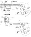
図1は、本発明の術具の一実施例の構成図であって、術具として鉗子を一例にして説明する。101は鉗子の主要部分を構成する長尺状の筒状部材、102は前記筒状部材101の内部にその長さ方向に移動可能に配置した内部部材として金属棒で形成したロッド、102aは係止部材、103は模擬する鉗子の把持感覚を実現する第1の把持機構、104は移動駆動力伝達手段としてのハンドル、104aはハンドル桿、104bは案内部材、104cは軸、105は前記筒状部材101の中間部の対する両側面に形成した開口部、106は前記開口部105を通して前記ロッド102の両側面に接触可能に配置し第1の把持機構103を構成する接触部材、107は第1の把持機構103を構成し前記接触部材106を開閉制御するネジ、108は第1の把持機構103を構成し模擬する鉗子の把持の状況に応じて前記ネジ107に回転力を与える傘歯車、109は第1の把持機構103を構成し前記傘歯車108を駆動するモータ、モータ109は図示しない手術シミュレータにより制御される。第1の把持機構103の要部を図1(b)に示す。
係止部材102aはロッド102の端部に形成され例えばピン状に形成する。ハンドル104は、ハンドル桿104aと、案内部材104bと、軸104cとを備える。案内部材104bは細長く変形され内部が空間部を有する長円状に形成され、長尺のハンドル桿104aを介してハンドル104に固着されるとともに、ハンドル桿104aの1箇所が軸104cを介して模擬術具本体例えば筒状部材101が延長した部材に取り付けられる。案内部材104bの長円状の内部空間部には前記ロッド102の係止部材102aが配置され、ハンドル104とロッド102とが連結される。ハンドル104の操作により、係止部材102aは案内部材104bの長円状の内部空間部を形成する側面を摺動移動することができる。図1(c)にハンドル104を軸104c中心に回転させるように操作した状態を示す。
図2は、本発明に用いるシミュレータの機能ブロック図である。201は模擬術具、202は把持機構、203は術具位置姿勢機構であり、模擬術具201の位置姿勢を示す。204は把持機構202が模擬する鉗子の位置(開閉状態)を検出する第1の検出部、205は術具位置姿勢機構203を構成する各部分の位置を検出する第2の検出部、206は術具の操作に対する応答を計算するシミュレーション計算部、207は第1の検出部205と第2の検出部207との位置情報により手術模擬計算をする手術模擬計算部、208は手術模擬計算部207の計算に基づき、模擬手術の操作者が見ることができるように画像を生成計算する表示計算部、209は把持機構202が模擬する鉗子の把持反力を計算する把持力計算部、210は把持反力以外の模擬術具201への反力を計算する反力計算部、211は表示計算部208が生成した画像を表示する表示部、212は把持力計算部209の計算による把持力を発生するように把持機構202を制御する第1の制御部、213は反力計算部210の計算による反力を発生するように術具位置姿勢機構203を制御する第2の制御部である。FIG. 1 is a configuration diagram of an embodiment of the surgical instrument of the present invention, and a forceps will be described as an example of the surgical instrument. 101 is a long cylindrical member constituting the main part of the forceps, 102 is a rod formed of a metal rod as an internal member disposed inside the cylindrical member 101 so as to be movable in its length direction, and 102a is an engagement member. A stop member, 103 is a first gripping mechanism that realizes the gripping force of the forceps to be simulated, 104 is a handle as a movement driving force transmission means, 104a is a handle rod, 104b is a guide member, 104c is a shaft, and 105 is the cylindrical
The
FIG. 2 is a functional block diagram of the simulator used in the present invention.
ロッド102の一端方向の部分には第1の把持機構103が設けてあり、他端にはハンドル104が連結されている。ハンドル104を駆動してロッド102を移動させたとき、一端方向の部分に第1の把持機構103が設けていることにより、実際のハンドル104の操作を模擬する。第1の把持機構103は臓器の一部を挟むような“開閉操作による感覚を模擬”するものであるが、実際の鉗子のように挟み状の形態を持つ必要はなく、挟み状形態物の開閉の感覚をロッド102を介してハンドル104に伝えるように模擬するものであればよい。ロッド102が移動可能として、ロッド102の一端は後述する円板301(図3)にユニバーサルジョイントで構成する第1の連結部材302により連結する。
筒状部材101はハンドル104とは反対方向の先端が術具位置姿勢機構203を介してシミュレータ装置の一部に連結される。術具位置姿勢機構203は、円板301、第1の連結部材302および3個の支持部材303,304,305で構成する。各支持部材303,304,305の各下方部分はモータ等の駆動装置を介してシミュレータ装置に設置され、各駆動装置の制御により円板301を所定の領域で自在に移動制御することができる。そして、鉗子本体を模擬する筒状部材101が円板301により移動が制御され、反力を受ける。A
The cylindrical member 101 has a distal end opposite to the handle 104 connected to a part of the simulator device via a surgical instrument position /
操作者は模擬術具を用いて、表示部211に表示されている手術状況に応じて、手術操作を行う。術具は手術操作によりその位置・姿勢を変化し、変化の状態は術具位置姿勢機構203の変化に現れ、その位置・姿勢変化を計測した第2の検出部205を介して手術模擬計算部207に送られ、表示計算部208でその変化が画像生成され、表示部211に表示される。
操作者が例えば、臓器として血管を鉗子により把持するとき、ハンドル104を握ると、ロッド102が引かれ移動する。ロッド102の移動量は第1の検出部204で検出される。第1の検出部204で検出された移動量は、前述の第2の検出部205からの術具の位置・姿勢の変化量とともに、手術模擬計算部207に取り込まれる。手術模擬計算部207は手術状況に応じた模擬計算をする。表示計算部208は、鉗子が血管を把持する状況の画像を生成し、表示部211に表示する。把持力計算部209は、把持物がない場合は少ない力で把持部が閉まり、把持部が血管にあたると把持を模擬して、血管の弾性に応じて、ハンドル104を握るときのロッド102の移動を接触部材106がロッド102と接触する面で発生する摩擦力による抵抗により操作を制限するように第1の制御部212を制御する。操作者はハンドル104にかける力に抗してロッド102の移動が摩擦力により制限されることで血管を把持する感覚をハンドル104の操作を通じて体感することができる。ロッド102の移動の制限制御は接触部材106をモータ109の駆動により閉制御して行う。反力計算部210は、術具位置姿勢機構203の移動に応じて円板301を移動させ、支持部材303,304,305にフィードバックし、支持部材303,304,305を駆動して、円板301の位置・姿勢を制御して模擬術具201に反力に応じた力を発生させる。The operator uses the simulated surgical tool to perform a surgical operation in accordance with the surgical situation displayed on the
For example, when an operator grasps a blood vessel as an organ with forceps, when the operator grasps the handle 104, the
図4は、第2の把持機構401を筒状部材101と円板301との間に介在させ、筒状部材101の長さ方向を軸とする回転に対する反力を提示する実施例を説明する図である。
図4において、401は第2の把持機構、402は搭載部材、403は筒状部材101の外側面に接触可能に配置し第2の把持機構401を構成する第2の接触部材、404は第2の把持機構401を構成し前記接触部材403を開閉制御するネジ、405は第2の把持機構401を構成し筒状部材101の長さ方向を軸とする回転操作の状況に応じて前記ネジ404に回転力を与える傘歯車、406は第2の把持機構401を構成し前記搭載部材402に搭載され前記傘歯車405を駆動するモータ、モータ406は図示しない手術シミュレータにより制御される。407は、前記搭載部材402を筒状部材101の周囲に回転可能にベアリングを内蔵して連結する第2の連結部材、408は、ユニバーサルジョイントで構成し、前記搭載部材402を円板301に連結する第3の連結部材である。したがって、図2における術具位置姿勢機構203は、実施例2において図4に示すように、円板301、第1の連結部材302、第3の連結部材408および3個の支持部材303,304,305で構成する。第2の把持機構401の要部を図4(b)に示す。FIG. 4 illustrates an embodiment in which a second gripping mechanism 401 is interposed between the tubular member 101 and the disc 301 to present a reaction force against rotation about the length direction of the tubular member 101. FIG.
In FIG. 4, 401 is a second gripping mechanism, 402 is a mounting member, 403 is disposed so as to be able to contact the outer surface of the cylindrical member 101, and a second contact member constituting the second
操作者が例えば、臓器として血管を鉗子により把持して鉗子を回転すると、筒状部材101の回転量は第2の検出部205で検出される。第2の検出部205で検出された回転量は、前述の第1の検出部204からのロッド102の移動量とともに、手術模擬計算部207に取り込まれる。手術模擬計算部207は手術状況に応じた模擬計算をする。表示計算部208は、鉗子が血管を把持回転する状況の画像を生成し、表示部211に表示する。把持物がない場合は少ない力で把持部が閉まり、抵抗なく筒状部材101を第2の連結部材407により搭載部材402上を滑らかに回転することができる。把持力計算部209は、把持部が血管にあたると把持を模擬して、血管の弾性に応じて、ハンドル104を握るときのロッド102の移動を接触部材106が制限するように第1の制御部212を制御する。このとき、把持力計算部209は、筒状部材101を回転すると、血管の弾性に応じて、筒状部材101の回転を第2の接触部材403が制限するように第1の制御部を制御する。操作者はハンドル104にかける力に抗して鉗子の回転すなわち筒状部材101の回転が制限されることで血管を回転変形する感覚をハンドル104の操作による筒状部材101の回転を通じて体感することができる。筒状部材101の回転の制限制御は第2の接触部材403をモータ406の駆動により閉制御して行う。回転制御の場合、反力計算部210は、術具位置姿勢機構203の回転移動に応じて円板301を移動させ、支持部材303,304,305にフィードバックし、支持部材303,304,305を駆動して、円板301の位置・姿勢を制御して模擬術具201に回転反力に応じた力を発生させる。 For example, when the operator grips a blood vessel as an organ with forceps and rotates the forceps, the rotation amount of the cylindrical member 101 is detected by the
101 筒状部材
102 ロッド
103 第1の把持機構
104ハンドル(移動駆動力伝達手段)
105 開口部
106 第1の接触部材
107 ネジ
108 傘歯車
109 モータ
101
105
Claims (1)
Translated fromJapanese長尺状の筒状部材と、前記筒状部材の内部にその長さ方向に移動可能に配置した内部部材と、
前記筒状部材後端に前記内部部材と連結して内部部材を筒状部材内の長さ方向に移動する移動駆動力伝達手段と、
前記筒状部材の中間部の対する両側面に形成した開口部を通して前記内部部材に接触可能に接触部材を配置し、手術シミュレーションにおける鉗子の把持の状況に応じて当該接触部材の接触力を制御し、発生する摩擦力による抵抗により操作を制限して鉗子の把持反力を模擬する把持機構と、を有し、
前記接触部材は、内部部材の両側面に接触するように配置し、把持機構を構成するモータを駆動し連結した傘歯車により回転力を与えられたネジにより開閉制御して接触力を制御することを特徴とする手術シミュレータに用いる鉗子。
A forceps used in a computer-controlled surgery simulator,
An elongated tubular member, and an internal member disposed inside the tubular member so as to be movable in the length direction thereof;
Moving driving force transmission means connected to the inner member at the rear end of the tubular member to move the inner member in the longitudinal direction in the tubular member;
A contact member is disposed so as to be able to contact the inner member through openings formed on both side surfaces of the intermediate portion of the cylindrical member, and the contact force of the contact member is controlled according to the forceps gripping situation in the surgical simulation.,possess a gripping mechanism for simulating gripping reaction force of the forcepsby limiting the operation by resistance caused by friction force generated,and
The contact member is disposed so as to be in contact with both side surfaces of the internal member, and the contact force is controlled by opening / closing control with a screw provided with a rotational force by a connected bevel gear by driving a motor constituting a gripping mechanism. Forceps used in a surgical simulator characterized by
Priority Applications (1)
| Application Number | Priority Date | Filing Date | Title |
|---|---|---|---|
| JP2012286773AJP6192932B2 (en) | 2012-12-28 | 2012-12-28 | Surgical simulator forceps |
Applications Claiming Priority (1)
| Application Number | Priority Date | Filing Date | Title |
|---|---|---|---|
| JP2012286773AJP6192932B2 (en) | 2012-12-28 | 2012-12-28 | Surgical simulator forceps |
Related Child Applications (1)
| Application Number | Title | Priority Date | Filing Date |
|---|---|---|---|
| JP2016215023ADivisionJP6214742B2 (en) | 2016-11-02 | 2016-11-02 | Surgical simulator forceps |
Publications (2)
| Publication Number | Publication Date |
|---|---|
| JP2014130184A JP2014130184A (en) | 2014-07-10 |
| JP6192932B2true JP6192932B2 (en) | 2017-09-06 |
Family
ID=51408641
Family Applications (1)
| Application Number | Title | Priority Date | Filing Date |
|---|---|---|---|
| JP2012286773AExpired - Fee RelatedJP6192932B2 (en) | 2012-12-28 | 2012-12-28 | Surgical simulator forceps |
Country Status (1)
| Country | Link |
|---|---|
| JP (1) | JP6192932B2 (en) |
Families Citing this family (3)
| Publication number | Priority date | Publication date | Assignee | Title |
|---|---|---|---|---|
| PL424841A1 (en)* | 2018-03-09 | 2019-09-23 | Laparo Spółka Z Ograniczoną Odpowiedzialnością | Manipulation and measuring unit of laparoscopic simulator |
| JP7201998B2 (en)* | 2019-02-20 | 2023-01-11 | 国立大学法人大阪大学 | surgical training device |
| CN111681490B (en)* | 2020-07-20 | 2021-11-16 | 桂林拓达机电工程有限公司 | Real operation panel of instructing of integrated form mechatronic |
Family Cites Families (2)
| Publication number | Priority date | Publication date | Assignee | Title |
|---|---|---|---|---|
| US5882206A (en)* | 1995-03-29 | 1999-03-16 | Gillio; Robert G. | Virtual surgery system |
| WO2003021553A1 (en)* | 2001-09-03 | 2003-03-13 | Xitact S.A. | Device for simulating a rod-shaped surgical instrument for generating a feedback signal |
- 2012
- 2012-12-28JPJP2012286773Apatent/JP6192932B2/ennot_activeExpired - Fee Related
Also Published As
| Publication number | Publication date |
|---|---|
| JP2014130184A (en) | 2014-07-10 |
Similar Documents
| Publication | Publication Date | Title |
|---|---|---|
| US12213755B2 (en) | Actuated grips for controller | |
| US10238461B2 (en) | Methods, systems, and devices for control of surgical tools in a robotic surgical system | |
| Talasaz et al. | The role of direct and visual force feedback in suturing using a 7-DOF dual-arm teleoperated system | |
| CN211827846U (en) | Medical simulation system | |
| GB2589458A (en) | A virtual reality surgical system including a surgical tool assembly with haptic feedback | |
| US20070018958A1 (en) | Force reflective robotic control system and minimally invasive surgical device | |
| JP6886976B2 (en) | Robotic surgical system with independent roll, pitch, and yaw scaling | |
| KR100934265B1 (en) | Circular Haptic Device and Haptic Interface for Gastrointestinal Endoscopy | |
| JP6762280B2 (en) | Forceps system | |
| CN107067921B (en) | A kind of force feedback apparatus that can be extended to seven freedom | |
| Talasaz et al. | Effect of force feedback on performance of robotics-assisted suturing | |
| CN113993669A (en) | Estimating joint friction and tracking error of a robotic end effector | |
| WO2011027329A2 (en) | Haptic interface for simulator, such as a colonoscopy simulator | |
| JP6192932B2 (en) | Surgical simulator forceps | |
| JP6214742B2 (en) | Surgical simulator forceps | |
| Ha-Van et al. | Design and characterization of an actuated drill mockup for orthopedic surgical training | |
| Santos-Carreras et al. | Influence of Force and Torque Feedback on Operator Performance in a VR‐Based Suturing Task | |
| KR100802136B1 (en) | Haptic device for firearm endoscope simulator | |
| Sun et al. | A novel end‐effector design for robotics in image‐guided needle procedures | |
| KR101231526B1 (en) | Reaction supplying apparatus for endoscope simulator | |
| Dargar et al. | System characterization of a novel haptic interface for natural orifice translumenal endoscopic surgery simulation | |
| Amato et al. | A versatile mechatronic tool for minimally invasive surgery | |
| Dargar et al. | A Decoupled 2 DOF Force Feedback Mechanism for the Virtual Translumenal Endoscopic Surgical Trainer (VTEST TM) | |
| Bleuler et al. | Haptic handles for robotic surgery | |
| Fan et al. | Control devices and steering strategies in pathway surgery |
Legal Events
| Date | Code | Title | Description |
|---|---|---|---|
| A621 | Written request for application examination | Free format text:JAPANESE INTERMEDIATE CODE: A621 Effective date:20151111 | |
| A131 | Notification of reasons for refusal | Free format text:JAPANESE INTERMEDIATE CODE: A131 Effective date:20160907 | |
| A977 | Report on retrieval | Free format text:JAPANESE INTERMEDIATE CODE: A971007 Effective date:20160907 | |
| A521 | Request for written amendment filed | Free format text:JAPANESE INTERMEDIATE CODE: A523 Effective date:20161102 | |
| A02 | Decision of refusal | Free format text:JAPANESE INTERMEDIATE CODE: A02 Effective date:20170407 | |
| A521 | Request for written amendment filed | Free format text:JAPANESE INTERMEDIATE CODE: A523 Effective date:20170623 | |
| A911 | Transfer to examiner for re-examination before appeal (zenchi) | Free format text:JAPANESE INTERMEDIATE CODE: A911 Effective date:20170706 | |
| TRDD | Decision of grant or rejection written | ||
| A01 | Written decision to grant a patent or to grant a registration (utility model) | Free format text:JAPANESE INTERMEDIATE CODE: A01 Effective date:20170802 | |
| A61 | First payment of annual fees (during grant procedure) | Free format text:JAPANESE INTERMEDIATE CODE: A61 Effective date:20170809 | |
| R150 | Certificate of patent or registration of utility model | Ref document number:6192932 Country of ref document:JP Free format text:JAPANESE INTERMEDIATE CODE: R150 | |
| R250 | Receipt of annual fees | Free format text:JAPANESE INTERMEDIATE CODE: R250 | |
| LAPS | Cancellation because of no payment of annual fees |