JP6189603B2 - Fire extinguisher - Google Patents
Fire extinguisherDownload PDFInfo
- Publication number
- JP6189603B2 JP6189603B2JP2013029564AJP2013029564AJP6189603B2JP 6189603 B2JP6189603 B2JP 6189603B2JP 2013029564 AJP2013029564 AJP 2013029564AJP 2013029564 AJP2013029564 AJP 2013029564AJP 6189603 B2JP6189603 B2JP 6189603B2
- Authority
- JP
- Japan
- Prior art keywords
- fire extinguishing
- fire
- storage device
- power storage
- agent
- Prior art date
- Legal status (The legal status is an assumption and is not a legal conclusion. Google has not performed a legal analysis and makes no representation as to the accuracy of the status listed.)
- Active
Links
Images


Classifications
- A—HUMAN NECESSITIES
- A62—LIFE-SAVING; FIRE-FIGHTING
- A62C—FIRE-FIGHTING
- A62C3/00—Fire prevention, containment or extinguishing specially adapted for particular objects or places
- A62C3/07—Fire prevention, containment or extinguishing specially adapted for particular objects or places in vehicles, e.g. in road vehicles
- A—HUMAN NECESSITIES
- A62—LIFE-SAVING; FIRE-FIGHTING
- A62C—FIRE-FIGHTING
- A62C3/00—Fire prevention, containment or extinguishing specially adapted for particular objects or places
- A62C3/16—Fire prevention, containment or extinguishing specially adapted for particular objects or places in electrical installations, e.g. cableways
- Y—GENERAL TAGGING OF NEW TECHNOLOGICAL DEVELOPMENTS; GENERAL TAGGING OF CROSS-SECTIONAL TECHNOLOGIES SPANNING OVER SEVERAL SECTIONS OF THE IPC; TECHNICAL SUBJECTS COVERED BY FORMER USPC CROSS-REFERENCE ART COLLECTIONS [XRACs] AND DIGESTS
- Y02—TECHNOLOGIES OR APPLICATIONS FOR MITIGATION OR ADAPTATION AGAINST CLIMATE CHANGE
- Y02E—REDUCTION OF GREENHOUSE GAS [GHG] EMISSIONS, RELATED TO ENERGY GENERATION, TRANSMISSION OR DISTRIBUTION
- Y02E60/00—Enabling technologies; Technologies with a potential or indirect contribution to GHG emissions mitigation
- Y02E60/10—Energy storage using batteries
Landscapes
- Health & Medical Sciences (AREA)
- Public Health (AREA)
- Business, Economics & Management (AREA)
- Emergency Management (AREA)
- Fire-Extinguishing By Fire Departments, And Fire-Extinguishing Equipment And Control Thereof (AREA)
- Fire-Extinguishing Compositions (AREA)
- Secondary Cells (AREA)
- Battery Mounting, Suspending (AREA)
Description
Translated fromJapanese本発明は、複数のリチウムイオン電池を収納した蓄電装置に設けて消火する消火装置に関する。 The present invention relates to a fire extinguishing apparatus that is provided in a power storage device that houses a plurality of lithium ion batteries and extinguishes fire.
近年、ガソリンや軽油を燃料としたエンジンを動力源とする自動車以外に、エンジンとモーターを搭載したハイブリッド自動車が急増している。この背景には原油価格の上昇により、低燃費車の需要が増加したことや、環境負荷低減の意識向上によりCO2排出量の少ないハイブリッド自動車の需要が増加したことにある。さらに、このようなハイブリッド車に加え、電気モーターのみを動力源とし、走行時のCO2排出量がゼロである電気自動車も徐々に普及がはじまっている。In recent years, hybrid vehicles equipped with engines and motors are rapidly increasing in addition to vehicles powered by engines powered by gasoline or light oil. This is due to the increase in demand for fuel-efficient vehicles due to the rise in crude oil prices and the increase in demand for hybrid vehicles with low CO2 emissions due to the increased awareness of reducing environmental impact. Furthermore, in addition to such hybrid vehicles, electric vehicles that use only electric motors as the power source and have zero CO2 emissions during travel are gradually becoming popular.
ハイブリッド自動車や電気自動車の車体には、複数の単電池を配列して直列且つ並列接続した高電圧且つ大容量の蓄電装置が搭載されている。蓄電装置はセルと呼ばれる単電池を複数接続した組電池で構成され、密閉容器に収納している。また蓄電装置に搭載する単電池は、従来のニッケル・水素電池から一般家庭でも充電が可能なリチウムイオン電池へ移行しており、今後も単電池の高性能化が期待されている。 A high-voltage and large-capacity power storage device in which a plurality of single cells are arranged and connected in series and in parallel is mounted on the body of a hybrid vehicle or an electric vehicle. The power storage device is composed of an assembled battery in which a plurality of unit cells called cells are connected, and is housed in a sealed container. In addition, the unit cell mounted in the power storage device has shifted from a conventional nickel-hydrogen battery to a lithium ion battery that can be charged even in a general home, and it is expected that the unit cell will have higher performance in the future.
また、航空機の分野においても、小型で容量が大きく軽量化に寄与するリチウムイオン電池を用いた蓄電装置を搭載した航空機が実用化され、運用を開始している。 Also, in the field of aircraft, an aircraft equipped with a power storage device using a lithium ion battery that is small in size and has a large capacity and contributes to weight reduction has been put into practical use and has started operation.
更に、近年、一般住宅、オフィス、公共施設などを対象にした定置型のリチウムイオン電池を用いた蓄電装置も急速に広がっており、リチウムイオン電池を用いたことで、数百Whから2〜3kWh程度の蓄電容量をもった建物内に簡単に設置して使用可能な小型の蓄電装置を実現している。 Furthermore, in recent years, power storage devices using stationary lithium ion batteries for general homes, offices, public facilities, etc. are also rapidly spreading. By using lithium ion batteries, several hundred Wh to 2-3 kWh A small power storage device that can be easily installed and used in a building having a certain level of power storage capacity has been realized.
定置型の蓄電装置は、建物内に引き込まれた商用交流系統のコンセント等に接続して入力した交流電力を直流電力に変換して蓄電し、テレビ、パーソナルコンピュータ等の電子機器、照明機器といった日常生活で重要度の高い負荷、所謂重要負荷を接続しておくことで、商用交流系統の停電時は勿論のこと、平常時にも、必要に応じて蓄電した直流電力を交流電力に変換して出力して動作するようにしている。 A stationary power storage device is connected to an outlet of a commercial AC system drawn into a building, etc., and converts AC power input to DC power to store it, and is used in daily life such as electronic equipment such as TVs and personal computers, and lighting equipment. By connecting loads of high importance in life, so-called important loads, the stored AC power is converted into AC power and output as needed, not only during a commercial AC power outage To make it work.
また、商用交流系統からの交流電力による蓄電装置の蓄電を、電気料金が安くなる深夜の時間帯に行い、消費電力が最大となる昼間の電力ピークの時間帯に、蓄電装置に蓄電した直流電力を交流電力に変換して負荷へ供給し、商用交流系統からの電力消費を低減し、節電と経済的な電力の活用を可能としている。 Also, the DC power stored in the power storage device during the daytime power peak time when the power consumption is maximized is stored in the midnight time when the electricity bill is reduced, and the AC power from the commercial AC system is stored. Is converted into AC power and supplied to the load, reducing the power consumption from the commercial AC system and making it possible to save power and use economical power.
しかしながら、このようなリチウムイオン電池を用いた蓄電装置にあっては、リチウムイオン電池を複数接続して大容量を実現しているが、リチウムイオン電池が内部ショートや過充電等の種々の原因で熱暴走した場合、電池温度が著しく上昇し、電池内部の圧力が上昇し、その結果、リチウムイオン電池の破裂や発火が起き、蓄電装置を火元とした電気火災が発生する恐れがある。 However, in such a power storage device using a lithium ion battery, a large capacity is realized by connecting a plurality of lithium ion batteries. However, the lithium ion battery has various causes such as an internal short circuit or overcharge. When the thermal runaway occurs, the battery temperature rises significantly and the pressure inside the battery rises. As a result, the lithium ion battery may rupture or ignite, which may cause an electric fire with the power storage device as the source of fire.
蓄電装置に収納したリチウムイオン電池は電解液にジメチルカーボネート、ジエチルカーボネートなどの可燃性液体を用いており、可燃性液体がある限り、条件がそろえば発火する。リチウムイオン電池の発火のメカニズムは熱暴走であり、セルの内部短絡、セル内部の異常発熱、外部短絡、外部異常過熱、過大電流、過大電圧などがトリガとなり、セル内部での温度上昇が発生し、この発熱がある限界値を越えると、その挙動はコントロール出来ずに連読的に、昇温反応を起こし昇温現象が発生する。これが熱暴走である。 A lithium ion battery housed in a power storage device uses a flammable liquid such as dimethyl carbonate or diethyl carbonate as an electrolytic solution. As long as there is a flammable liquid, it ignites when conditions are met. The ignition mechanism of lithium-ion batteries is thermal runaway, and the internal temperature of the cell increases due to internal short circuit, abnormal heating inside the cell, external short circuit, external abnormal overheating, excessive current, excessive voltage, etc. When this exotherm exceeds a certain limit value, the behavior cannot be controlled and the temperature rising reaction is caused in a continuous manner, and the temperature rising phenomenon occurs. This is a thermal runaway.
リチウムイオン電池の熱暴走時の挙動は、短時間に急激な昇温反応を示し、電解液が急激に熱せられ、膨張し、ガス化して噴出し、セルに設けた安全弁が作動(破裂)して電解液を噴出し、電解液が可燃性液体であることからセルから火炎が噴出する。 The behavior of a lithium-ion battery during thermal runaway shows a rapid temperature rise reaction in a short time, the electrolyte is heated suddenly, expands, gasifies and ejects, and the safety valve provided in the cell is activated (ruptured). The electrolyte is ejected, and the flame is ejected from the cell because the electrolyte is a flammable liquid.
セルから噴出する火炎の度合いはリチウムイオン電池の充電量による異なることが、各種の火災実験の結果として報告されている。リチウムイオン電池の発熱分解時に放出される酸素量は、充電状態の違いで異なっており、満充電(SOC100%)時がもっとも酸素量放出が多いといわれている。このため充電量の多い電池と充電量の少ない電池では酸素放出量の違いが存在し、充電量が多いほどセルから火炎が強く噴出し、満充電の場合には爆発的な火炎の噴出となっている。 It has been reported as a result of various fire experiments that the degree of flame erupted from the cell differs depending on the charge amount of the lithium ion battery. The amount of oxygen released at the time of exothermic decomposition of a lithium ion battery differs depending on the state of charge, and it is said that the amount of released oxygen is greatest when fully charged (
密閉容器を使用した蓄電装置に収納している複数のリチウムイオン電池のいずれかが熱暴走により発火した場合、セルから噴出した火炎は容器内の空き空間に広がって容器内部を火炎で満たし、容器内の酸素が火炎により消費されてなくなっても、セル自体からの酸素放出が続くために噴出する電解液の火炎は衰えることがなく、蓄電装置の内部温度が急激に上昇し、隣接するリチウムイオン電池が加熱され、連鎖的に熱暴走を起こす可能性がある。またセルから噴出した電解液は高い電気導電性をもち、そのため蓄電内部に噴出した場合に、リチウムイオン電池の電極端子間や接続バーの間に付着すると外部短絡を引き起こし、過大な短絡電流が流れることで、隣接するリチウムイオン電池が連鎖的に熱暴走を起こす可能性がある。 If any of the multiple lithium-ion batteries stored in a power storage device that uses a sealed container ignites due to thermal runaway, the flame erupted from the cell spreads into the empty space in the container and fills the container with the flame. Even if the oxygen in the inside is no longer consumed by the flame, the oxygen flame from the cell itself does not fade because the oxygen release from the cell continues, the internal temperature of the power storage device rises rapidly, and the adjacent lithium ion The battery may be heated, causing thermal runaway in a chain. In addition, the electrolyte sprayed from the cell has high electrical conductivity. Therefore, if it is sprayed inside the battery, if it adheres between the electrode terminals of the lithium ion battery or between the connection bars, an external short circuit will occur and an excessive short circuit current will flow. As a result, adjacent lithium ion batteries may cause thermal runaway in a chained manner.
このような熱暴走による発火の問題に対しては、各種の安全対策がとられ、安全性の向上が日々図られている。この点に関し「電池の安全性向上が見られるのは事実である。しかし、火災・爆発に至る確率を小さくしているのであって、火災・爆発が起こらないことを意味するものではない」とする学識経験者の見解も示されている。 Various safety measures are taken against the problem of ignition due to such thermal runaway, and safety is improved every day. In this regard, “It is true that the safety of the battery can be improved. However, the probability of a fire / explosion is reduced, and it does not mean that there will be no fire / explosion”. The views of those who have academic experience are also shown.
しかしながら、従来、自動車、航空機、更に建物にリチウムイオン電池を収納した蓄電装置を設置した場合の電気火災に対し、密閉容器の外部で起きた火災に対応して消火抑制する消火装置や消火設備は各種提案され実用化されているが、密閉容器内で起きたリチウムイオン電池の熱暴走に起因した発火に対応して直接的に消火抑制するために有効な消火装置や消火設備は実現されていない。 However, conventionally, there are no fire extinguishing devices and fire extinguishing equipment that suppress fire extinguishing in response to a fire that occurred outside a sealed container against an electric fire when a power storage device containing a lithium ion battery is installed in a car, an aircraft, or a building. Various proposals have been put to practical use, but no effective fire extinguishing device or fire extinguishing equipment has been realized to directly control fire extinguishing in response to ignition caused by thermal runaway of a lithium ion battery that has occurred in a sealed container. .
また蓄電装置の電気火災が発生した際に、従来の水系消火設備による消火活動は、火災を消火或いは抑制するどころか、感電事故等の二次災害を誘発する危険性が高い。 In addition, when an electrical fire of a power storage device occurs, the fire extinguishing activity by the conventional water-based fire extinguishing equipment has a high risk of inducing a secondary disaster such as an electric shock accident as well as extinguishing or suppressing the fire.
本発明は、蓄電装置の容器内で起きているリチウムイオン電池の異常に伴う火災を直接的に消火抑制して連鎖的な火災の拡大を阻止することを可能とする消火装置を提供することを目的とする。 It is an object of the present invention to provide a fire extinguishing apparatus that can directly suppress a fire associated with an abnormality of a lithium ion battery occurring in a container of a power storage device and prevent the spread of a chain fire. Objective.
(消火装置)
本発明は、複数のリチウムイオン電池を収納した蓄電装置に設ける消火装置に於いて、
蓄電装置の内部空き空間に対応した所定量の粉末絶縁剤が充填された絶縁剤収納手段と、
絶縁剤収納手段に充填された粉末絶縁剤を加圧する加圧手段と、
リチウムイオン電池の異常に伴う火災を検出した場合に、加圧手段の作動により絶縁剤収納手段に充填した粉末絶縁剤を加圧し、蓄電装置内に粉末絶縁剤を消火砂として放出させる消火制御手段と、
を備え、
加圧手段は、一端を絶縁剤収納手段内に開口し、他端を蓄電装置内に開口する放出管を備え、固形消化剤の燃焼により粉末絶縁剤を加圧することを特徴とする。
(Fire extinguishing equipment)
The present invention provides a fire extinguishing device provided in a power storage device containing a plurality of lithium ion batteries.
Insulating material storage means filled with a predetermined amount of powdered insulating material corresponding to the internal empty space of the power storage device;
A pressurizing means for pressurizing the powder insulating agent filled in the insulating agent storage means;
Fire extinguishing control means that pressurizes the powder insulating agent filled in the insulating material storing means by the operation of the pressurizing means and releases the powder insulating material as fire extinguishing sand in the power storage device when a fire due to abnormality of the lithium ion battery is detected When,
With
The pressurizing means includes a discharge pipe having one end opened in the insulating material storing means and the other end opened in the power storage device, andpressurizes the powder insulating agent by burning the solid digestive agent .
(固形消火剤を加圧源とする消火装置)(Fire extinguishing equipment using a solid fire extinguisher as a pressure source)
加圧手段は、The pressurizing means is
一端を閉鎖すると共に他端を絶縁剤収納手段側に開口し、燃焼により消火用エアロゾルを発生する固形消火剤が収納された固形消火剤収納部と、A solid fire extinguisher storage portion containing a solid fire extinguisher that closes one end and opens the other end to the insulating agent storage means side and generates a fire extinguishing aerosol by combustion;
固形消火剤収納部の開口側に配置された火炎噴出防止部材と、A flame ejection preventing member disposed on the opening side of the solid fire extinguishing agent storage unit;
を備える。Is provided.
(加圧手段及び消火制御手段)(Pressurizing means and fire extinguishing control means)
加圧手段は、放出管を封止し、粉末絶縁剤の加圧により破れる封止部材を備える。The pressurizing means includes a sealing member that seals the discharge tube and is broken by pressurization of the powder insulating agent.
消火制御手段は、Fire extinguishing control means
火災を検出した場合に、加圧手段を作動させると共に外部に消火起動検出信号を出力する起動回路部と、An activation circuit that activates the pressurizing means and outputs a fire extinguishing activation detection signal to the outside when a fire is detected;
起動回路部との間を信号線で接続したコネクタと、A connector that is connected to the starter circuit with a signal line;
コネクタに着脱自在に設けられ、消火起動検出信号を外部に出力する信号線をコネクタに接続するプラグと、A plug that is detachably provided on the connector, and that connects a signal line for outputting a fire extinguishing start detection signal to the outside;
を備える。Is provided.
起動回路部は、ヒータの通電加熱により固形消火剤を燃焼させる。The starting circuit unit burns the solid fire extinguisher by energization heating of the heater.
(熱感知ケーブル)
消火制御手段は、火災による熱を受けた場合に、絶縁被覆の溶融により一対の信号線を短絡状態に接触させる熱感知ケーブルを備え、当該熱感知ケーブルは、蓄電装置に収納された全てのリチウムイオン電池に備わる安全弁の近傍を通るように布設される。
(Thermal sensing cable)
The fire extinguishing control means includes a heat sensing cablethat brings a pair of signal wires into a short-circuited state by meltingthe insulation coating when receiving heat froma fire, and the heat sensing cableincludes all the lithium batteries storedin the power storage device. Ruis laid so as to pass through the vicinity of the safety valveprovided in the ion cell.
(消火装置の配置場所)
消火装置は、複数のリチウムイオン電池が収納された電池収納容器の蓋部材の上部外側、又は当該蓋部材の内側に配置される。
(Location of fire extinguishing equipment)
The fire extinguishing device is arrangedonthe outer side ofthe upper part of thelid member ofthe battery storage containerin which aplurality of lithium ion batteriesare stored, or onthe inner side of thelid member .
(基本的な効果)
本発明の消火装置は、蓄電装置に収納した複数のリチウムイオン電池の何れかが内部ショートや過充電等の種々の原因で熱暴走して破裂や発火が起きた場合に、蓄電装置の空き空間に見合った十分な量の粉末絶縁剤を蓄電装置内へ放出するようにしたため、蓄電装置内の空き空間が放出された粉末絶縁剤で充満され、熱暴走したリチウムイオン電池から噴出している電解液の火炎を粉末絶縁剤により包み込むと共に霧化した電解液を吸着し、粉末絶縁剤が所謂消火砂として機能することで火炎を消火抑制し、他のリチウムイオン電池の加熱を抑えて連鎖的な熱暴走を防止可能とし、最悪であっても蓄電装置内の火災に留め、外部にまで及ぶ火災の拡大を未然に防止することを可能とする。(Basic effect)
The fire extinguishing apparatus of the present invention is a free space in a power storage device when any of a plurality of lithium ion batteries housed in the power storage device is ruptured or ignited due to thermal runaway due to various causes such as internal short circuit or overcharge. An amount of powder insulation suitable for the battery is discharged into the power storage device, so that the empty space in the power storage device is filled with the discharged powder insulation and the electrolysis ejected from the thermally runaway lithium ion battery Enclose the liquid flame with the powder insulation and adsorb the atomized electrolyte, and the powder insulation functions as so-called fire extinguishing sand to suppress the fire extinction and suppress the heating of other lithium ion batteries The thermal runaway can be prevented, and even in the worst case, it is possible to keep the fire inside the power storage device and prevent the fire from spreading to the outside.
また、熱暴走したリチウムイオン電池から電解液が噴出している空き空間に粉末絶縁剤を放出することで、霧化した電解液と粉末絶縁剤が混合し、粉末絶縁剤と混合した電解液の導電性が低下して絶縁抵抗が高くなり、粉末絶縁剤と混合した電解液が他のリチウムイオン電池の電極端子間やバスバー(電極接続バー)間に付着しても、導電性が低下したことで短絡電流を抑制し、外部短絡による連鎖的な熱暴走を確実に防止可能とする。 Also, by discharging the powder insulation from the thermal runaway lithium-ion battery into the empty space where the electrolyte is jetting, the atomized electrolyte and the powder insulation are mixed, and the electrolyte mixed with the powder insulation is mixed. The electrical conductivity is lowered and the insulation resistance is increased, and the electrical conductivity is lowered even if the electrolyte mixed with the powder insulation adheres between the electrode terminals and bus bars (electrode connection bars) of other lithium ion batteries. By suppressing the short circuit current, it is possible to reliably prevent chain thermal runaway due to an external short circuit.
(粉末絶縁剤による効果)
また、粉末絶縁剤として雲母粉末剤を使用することで、高い絶縁抵抗が確保できると共に、高い耐熱性が確保でき、また市販されている工業用の乾式粉砕雲母粉を利用することで、コスト低減ができる。(Effects of powder insulation)
In addition, by using mica powder as a powder insulation agent, high insulation resistance can be secured, high heat resistance can be secured, and cost can be reduced by using commercially available dry pulverized mica powder. Can do.
また、雲母粉末剤などの粉末絶縁剤に所定量の粉末消火剤を混合することで、粉末絶縁剤による消火砂としての機能に加え、リチウムイオン電池から噴出している火炎に粉末消火剤を直接噴射して消火抑制することができる。 Moreover, by mixing a predetermined amount of powder fire extinguishing agent with a powder insulating agent such as mica powder agent, in addition to the function as fire extinguishing sand by the powder insulating agent, the powder fire extinguishing agent is directly applied to the flame ejected from the lithium ion battery. Injecting can suppress fire extinguishing.
(固形消火剤を加圧源とした場合の効果)
また、粉末絶縁剤の加圧源として、固形消火剤の燃焼により発生する消火用エアロゾルを用いるため、通常状態では固形消火剤を粉末絶縁剤から隔離して収納するだけでよく、耐圧が要求されない小型の加圧源とすることができ、また火災を検知した場合は、固形消火剤の燃焼による消火用エアロゾルの発生による加圧で継続的に、蓄電装置内に粉末絶縁剤を放出することができる。(Effect when solid fire extinguishing agent is used as pressure source)
In addition, since the fire extinguishing aerosol generated by the combustion of the solid fire extinguisher is used as the pressure source of the powder insulating agent, it is only necessary to store the solid fire extinguisher separately from the powder insulating agent under normal conditions, and no pressure resistance is required. A small pressure source can be used, and if a fire is detected, powder insulation can be continuously released into the electricity storage device by pressurization due to the generation of fire-extinguishing aerosol by burning solid extinguisher. it can.
また、粉末絶縁剤を加圧するために固形消火剤の燃焼により発生する消火用エアロゾルは、2μm程度の微粒子であり、塩化カリウム、塩化ナトリウム、炭酸ナトリウム、硫酸ナトリウムなどを主成分とし、これに窒素、二酸化炭素、水蒸気などが含まれ、水系消火剤を使用できない電気火災に好適であり、このため消火装置は、蓄電装置内に、粉末絶縁剤と消火用エアロゾルを混合して放出することとなり、リチウムイオン電池の火災に対し、より高い消火抑制を行うことが可能となる。 In addition, fire extinguishing aerosol generated by burning solid fire extinguishing agent to pressurize powder insulation is fine particles of about 2 μm, mainly composed of potassium chloride, sodium chloride, sodium carbonate, sodium sulfate, etc., and nitrogen. It is suitable for electric fires that contain carbon dioxide, water vapor, etc., and water-based extinguishing agents cannot be used.For this reason, the fire extinguishing device mixes and discharges the powder insulating agent and the fire extinguishing aerosol into the power storage device, It becomes possible to perform higher fire suppression for a fire of a lithium ion battery.
(不活性ガスを加圧源とした場合の効果)
また、粉末絶縁剤の加圧源として、ガスボンベに加圧充填した窒素ガスや二酸化炭素ガスなどの不活性ガスを用いるため、ガスボンベは耐圧が要求されるが、蓄電装置の空き空間の容積が小さいことから、必要とする不活性ガスの量も少なく済み、小型の加圧源とすることができる。(Effects when inert gas is used as a pressure source)
Further, since an inert gas such as nitrogen gas or carbon dioxide gas pressurized and filled in the gas cylinder is used as a pressure source for the powder insulating agent, the gas cylinder is required to have a pressure resistance, but the volume of the empty space of the power storage device is small. Therefore, the amount of the inert gas required is small, and a small pressure source can be obtained.
また、不活性ガスとして窒素ガスや二酸化炭素ガスを用いた場合には、蓄電装置内に、粉末絶縁剤と窒素ガス又は二酸化炭素ガスを混合して放出することとなり、窒素ガス又は二酸化炭素ガスによる窒息消火が加わることで、リチウムイオン電池の火災に対し、より高い消火抑制を行うことが可能となる。 In addition, when nitrogen gas or carbon dioxide gas is used as the inert gas, the powder insulating agent and nitrogen gas or carbon dioxide gas are mixed and released into the power storage device. By adding suffocation fire extinguishing, it becomes possible to perform higher fire extinguishing suppression against a fire of a lithium ion battery.
また、不活性ガスによる加圧で蓄電装置内に粉末絶縁剤を放出した場合、蓄電装置の内部圧力が増加するが、蓄電装置の内部圧力の増加に伴う雰囲気を導入しフィルタを通して外部に排出する排出部を消火装置に設けることで、蓄電装置の内部圧力の増加を抑え、蓄電装置の破裂を防止する。 In addition, when the powder insulating agent is released into the power storage device by pressurizing with an inert gas, the internal pressure of the power storage device increases, but the atmosphere accompanying the increase in the internal pressure of the power storage device is introduced and discharged to the outside through the filter. By providing the discharge unit in the fire extinguishing device, an increase in the internal pressure of the power storage device is suppressed and the power storage device is prevented from bursting.
(熱感知ケーブルによる効果)
また、蓄電装置に収納したリチウムイオン電池の異常に伴う電気火災の検知は、例えば熱感知ケーブルがリチウムイオン電池の熱暴走に伴う火炎の熱を受けた場合の絶縁被覆の溶融により一対の信号線を短絡状態に接触させることで検知しており、温度センサなどを使用した場合に必要な火災を検知する閾値温度の設定や、閾値と検出温度の比較判断を不要とし、簡単且つ確実に、リチウムイオン電池の異常に伴う火災を検知して消火抑制できる。(Effect of heat sensing cable)
In addition, detection of an electric fire accompanying abnormality of a lithium ion battery stored in a power storage device is performed by, for example, a pair of signal lines due to melting of an insulation coating when a heat sensing cable receives heat from a flame accompanying thermal runaway of a lithium ion battery. The battery is detected in contact with the short-circuited state, and it is not necessary to set a threshold temperature to detect a necessary fire when using a temperature sensor, or to compare and judge the threshold and the detected temperature. Fires associated with ion battery abnormalities can be detected and extinguished.
また、熱感知ケーブルを蓄電装置に収納している全てのリチウムイオン電池に設けた安全弁の近傍を横切るように布設するため、熱感知ケーブルの布設という簡単な構成により、全てのリチウムイオン電池の各々に対し異常に伴う火災を確実に検出して消火抑制ができる。 In addition, since the heat sensing cable is laid so as to cross the vicinity of the safety valve provided in all the lithium ion batteries housed in the power storage device, each of the lithium ion batteries is provided with a simple configuration of the heat sensing cable. On the other hand, it is possible to reliably detect fires associated with abnormalities and suppress fire extinguishing.
[消火装置の構成]
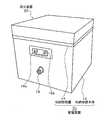
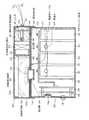
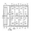
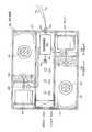
図1は本発明による消火装置を外付けした蓄電装置を示した斜視図、図2は固形消火剤を加圧源とした図1の消火装置及び蓄電装置の縦断面を示した断面図、図3は蓄電装置の蓋を外して装置本体内を示した平面図、図4は消火装置の蓋を外して本体内部を示した平面図である。[Configuration of fire extinguishing device]
FIG. 1 is a perspective view showing a power storage device with an external fire extinguishing device according to the present invention. FIG. 2 is a cross-sectional view showing a longitudinal section of the fire extinguishing device and power storage device of FIG. 3 is a plan view showing the inside of the apparatus main body with the lid of the power storage device removed, and FIG. 4 is a plan view showing the inside of the main body with the lid of the fire extinguishing apparatus removed.
(蓄電装置の概要)
図1、図2及び図3に示すように、蓄電装置10は例えば航空機用であり、上部に開口した箱型の収納容器本体12と、収納容器本体12の開口に装着してビスなどで固定した収納容器蓋14を備え、収納容器本体12と収納容器蓋14で蓄電装置10の収納容器を構成する。なお、蓄電装置10は、電池モジュール或いは電池パックとも呼ばれる。(Outline of power storage device)
As shown in FIGS. 1, 2, and 3, the
収納容器本体12の手前側の側壁には、蓄電装置10の正極出力端子16aと負極出力端子16b、及び各種の制御信号や検出信号を入出力する信号線を接続するコネクタ18を取付けている。 A
収納容器本体12には、組電池として例えば8個のリチウムイオン電池20を収納している。リチウムイオン電池20は、単電池(電池セル)として知られた非水電解質二次電池であり、例えば、アルミニウムまたはアルミニウム合金で形成した矩形箱型の外装容器に、非水電解液と共に電極体を収納している。 For example, eight
リチウムイオン電池20の電極体は、例えば、正極板及び負極板をその間にセパレータを介在させて渦巻き状に捲回すことにより、矩形形状に形成している。リチウムイオン電池20の外装容器の上端には正極及び負極となる一対の電極端子22を取出している。またリチウムイオン電池20の一方の側壁には安全弁25を設けている。安全弁25は外装容器に設けた開口を薄いアルミニウム板で閉鎖しており、熱暴走などにより内部圧力が増加した場合、所定圧力で作動(破裂)して外装容器の破裂を防止する。 The electrode body of the
ここで、リチウムイオン電池20の外形サイズは、例えば(高さ=170mm〜180mm)×(横幅=130mm〜140mm)×(奥行=50mm〜60mm)程度となる。また蓄電装置の外形サイズは、例えば(高さ=200mm〜220mm)×(横幅=270mm〜290mm)×(奥行=320mm〜340mm)程度となる。 Here, the external size of the
収納容器本体12の内部には、8個のリチウム電池20を2列に4個並べて収納しており、正極と負極の電極端子22が交互に向かい合うように収納し、これにより隣接する電池間の正極と負極の電極端子22の間にプレート状のバスバー(電極接続バー)24を装着し、8個のリチウムイオン電池を直列接続し、直列接続した場合の両端となる正極と負極の電極端子22をバスバー24により縦置きで収納した回路基板28の一方に連結している。
Inside the
回路基板28にはバッテリーマネジメントユニット(MBU)が実装され、電池電圧、内部温度を監視し、異常を検出した場合は、充電を停止するように外部に設置した充電器に信号を出力する機能を備えている。 A battery management unit (MBU) is mounted on the
リチウムイオン電池20の安全弁25は例えば正極の電極端子22側の側面に設けており、収納容器本体12に組み込んだ場合、図3の平面図に示すように、安全弁25は外側又は他の電池と相対する中央側に位置している。 The
リチウムイオン電池20の平均セル電圧を例えば3.5ボルトとすると、図3に示す8個のリチウムイオン電池20の直列接続により、組電池の電圧は28ボルトとなり、蓄電装置10の正極出力端子16aと負極出力端子16bの電圧も28ボルトとなる。なお、リチウムイオン電池20の数は、必要とする組電池の必要電圧に対応した数とする。また、複数のリチウムイオン電池20の接続は、所定数のリチウムイオン電池を並列接続した組電池とし、この組電池を複数直列接続しても良い。 If the average cell voltage of the
[消火装置の概要]
図1、図2及び図4に示すように、蓄電装置10における収納容器蓋14の上部に消火装置30を外付けにより固定配置している。[Outline of fire extinguishing equipment]
As shown in FIGS. 1, 2, and 4, a
消火装置30は、蓄電装置10の収納容器内に収納したリチウムイオン電池20の熱暴走に伴う火災を検出した場合に、固形消火剤の燃焼により発生した消火用エアロゾルを加圧源として、消火装置30に充填している粉末絶縁剤を蓄電装置10内に放出して消火抑制する。
When the
消火装置30は装置本体30aと蓋部材30bで構成した密閉容器であり、横幅と奥行を蓄電装置10と同じにした箱型形状をもつ。装置本体30a内は図4の平面図に示すように、仕切板41により3つの区画に分け、両側の区画に消火装置30の絶縁剤収納手段と加圧手段を各々設け、中央の区画に消火制御手段を設けている。
The
(絶縁剤収納手段の構成)
消火装置30の絶縁剤収納手段となる絶縁剤収納部32には、粉末絶縁剤として雲母粉末剤34を充填している。雲母粉末剤34は工業用として市販されている乾式粉砕雲母粉を使用することができ、例えば平均粒子径を5〜10μmとした超微粒子の雲母粉が好適である。雲母粉は、体積抵抗率が108Ω−m以上と高い電気絶縁性をもち、また熱分解温度も900〜1000℃程度と高い耐熱性を備える。
(Configuration of insulating agent storage means)
An insulating
絶縁剤収納部32に充填する雲母粉末剤34の量は、蓄電装置10の内部空き容積に対応した所定量、例えば内部空き空間の容積と同程度の量とする。蓄電装置10に収納しているリチウムイオン電池20の何れかが熱暴走を起して安全弁25が作動(破裂)して発火した電解液を噴出した場合、電解液の噴出による火炎は蓄電装置10の内部空き空間に広がることから、この内部空き空間にその容積と同程度の量の雲母粉末剤34を放出することで、蓄電装置10の内部空き空間を雲母粉末剤34で充満させることを可能とする。 The amount of the
また、粉末絶縁剤としての雲母粉末剤34に所定量の粉末消火剤を混合し、消火抑制効果を更に高めるようにしても良い。この粉末消火剤としては、木材、紙、繊維などの普通火災A、灯油、ガソリンなどの油類の火災B、配電盤、コンセントなどの電気火災Cに対応したABC式の粉末消火剤とする。 Moreover, you may make it further improve a fire-extinguishing suppression effect by mixing a predetermined amount of powder fire-extinguishing agents with the
(加圧手段の構成)
消火装置30の加圧手段は、固形消火剤収納部40、火炎噴出防止部材50、放出管36及び封止部材38で構成する。(Configuration of pressurizing means)
The pressurizing means of the
固形消火剤収納部40は、仕切部材44により一端を閉鎖すると共に他端を絶縁剤収納部32側に開口し、固形消火剤42を収納している。 The solid fire
固形消火剤42は中央横方向に通し穴を形成し、通し穴の開口側に火薬等を使用した点火剤46を埋込み配置し、更に、点火剤46の中には点火に使用するヒータ48を埋込み配置している。固形消火剤42に設けた通し穴は、点火剤46により固形消火剤42に点火した場合に、通し穴から外側に向って固形消火剤42を効率良く燃焼させる役割を果たす。 The
点火剤46として火薬を使用した場合、ヒータ48の通電加熱による点火剤46の起爆により発生する爆風を加圧源として、絶縁剤収納部32に収容した雲母粉末剤34を爆風により急速に攪拌加圧し、また爆風により発生した強い圧力で放出管36の封止部材38を破り、放出管36から蓄電装置10の内部に雲母粉末剤34を短時間に放出可能とする。 When explosive is used as the igniting
固形消火剤42は、燃焼により消火用エアロゾルを発生し、絶縁剤収納部32に充填している雲母粉末剤34を蓄電装置10の内部に放出するための加圧源として機能すると共に消火剤として機能する。消火用エアロゾルは、2μm程度の超微粒子であり、その主成分は、金属の酸化物、炭酸塩あるいは燐酸塩あるいはその混合物を含有している。 The
具体的には、塩化カリウム、塩化ナトリウム、炭酸ナトリウム、硫酸ナトリウムなどを主成分とし、これに窒素、二酸化炭素、水蒸気などが含まれている。このような主成分を持つ消火用エアロゾルにあっては、消火用エアロゾルそのものに毒性がなく、環境に優しい発生ガスということができる。 Specifically, potassium chloride, sodium chloride, sodium carbonate, sodium sulfate and the like are the main components, and nitrogen, carbon dioxide, water vapor and the like are contained therein. In the fire extinguishing aerosol having such a main component, the fire extinguishing aerosol itself is not toxic and can be said to be an environmentally friendly generated gas.
固形消火剤42の燃焼により発生した消火用エアロゾルによる消火作用は、火災の発生により燃焼している燃焼の活性中心を消滅、抑制する作用により消火を行うものであり、水系消火剤を使用することのできない電気火災に好適な消火作用が得られる。 The fire extinguishing action by the fire extinguishing aerosol generated by the combustion of the
固形消火剤42の量は例えば蓄電装置10の内部空き容積に応じて決める。閉鎖空間となる消火対象エリア1立方メートル当たりを消火するに必要な消火用エアロゾルを発生するための固形消火剤42の重量は、80グラム〜200グラム程度であり、これに基づき、消火対象とする蓄電装置10の内部空き容積に応じた量の固形消火剤42を収納している。 The amount of the
本実施形態の消火装置30が消火対象とする蓄電装置10の内容積は、例えば0.02立方メートル程度であり、これに複数のリチウムイオン電池20で構成した組電池、回路基板、バスバー等を収納することから、実際の内部空き容積は更に小さなものとなる。例えば蓄電装置10の内部空き容積を0.01立方メートルとした場合に必要な固形消火剤の重量は8グラム〜20グラム程度となる。 The internal volume of the
従来から電気設備等に用いられる消火設備として、ガス消火設備や粉末消火設備が一般に使用されているが、これらの消火設備は消火剤を放出するにあたり多量の高圧ガスを必要とする。その為、密閉度の高い収納容器内で消火用ガスや粉末を放出した場合は、収納容器の破裂に繋がり消火効果の低減や火災の延焼拡大の可能性がある。本実施形態の消火装置30では収納容器内の加圧は点火剤46に点火した短時間であり、その後は少量の固形消火剤42の燃焼により発生するエアロゾル放出による微少加圧であるため、従来のガス消火設備や粉末消火設備と比較して蓄電装置10内の圧力上昇は非常に小さく、蓄電装置10の破裂は回避できる。 Conventionally, gas fire extinguishing equipment and powder fire extinguishing equipment are generally used as fire extinguishing equipment used for electric equipment and the like, but these fire extinguishing equipment requires a large amount of high-pressure gas to release a fire extinguishing agent. For this reason, if fire extinguishing gas or powder is released in a highly sealed storage container, the storage container may burst, reducing the fire-extinguishing effect and expanding the spread of fire. In the
固形消火剤42を収納した固形消火剤収納部40の開口側には火炎噴出防止部材50を配置する。火炎噴出防止部材50の具体例としては、ガラスや磁器などの細径パイプを複数並べて炎の噴出しを抑制する構造、複数の金網を分離配置して炎の噴出しを抑制する構造、ガラスや磁器などのボールを複数配置して炎の噴出しを抑制する構造、更には複数の金網の間にガラスや磁器などのボールを複数配置して炎の噴出しを抑制する構造とする。
A flame
火炎噴出防止部材50に続いては複数のノズル孔54を形成した仕切部材52を配置し、絶縁剤収納部32側に点火剤46の起爆により発生した爆風により破れる薄い封止部材56を設けて閉鎖し、絶縁剤収納部32に充填している雲母粉末剤34が入らないようにしている。ノズル孔54を閉鎖する封止部材56は、アルミニウム箔、合成樹脂薄膜などを使用し、ノズル孔54の外側に接着固定する。
A
放出管36は一端を絶縁剤収納部32に開口すると共に、他端を収納容器蓋14を貫通して蓄電装置10内に開口し、その入口側に粉末雲母剤34の加圧により破れる封止部材38を配置し、粉末雲母剤34が蓄電装置10内に落下しないように封止している。放出管36を封止する封止部材38は、封止部材56と同様、アルミニウム箔、合成樹脂薄膜などを使用し、放出管36の入口側に接着固定する。 One end of the
放出管36の蓄電装置10側は有底であり、底部及びその周囲に開口を形成し、加圧供給された雲母粉末剤34を、下方及び横方向に拡散放出可能としている。 The
(消火制御手段の構成)
消火装置30の消火制御手段は、熱感知ケーブル64を用いた火災検出部、起動回路部60、コネクタ62、プラグ63を備える。
(Configuration of fire extinguishing control means)
The fire extinguishing control means of the
図4に示した消火装置30の中央の区画には起動回路部60を収納しており、起動回路部60から火災検知部として機能する熱感知ケーブル64を、絶縁シール65を介して蓄電装置10内に引き出して布線している。熱感知ケーブル64は、ビニールなどの樹脂で絶縁被覆した2本の撚られた信号線であり、2本の信号線の間に起動回路部60から電圧を印加しており、火災による熱を受けた場合の絶縁被覆の溶融により一対の信号線が短絡状態に接触し、感知電流が流れることで火災を検出する。
The
蓄電装置10に引き込まれた熱感知ケーブル64は、蓄電装置10に収納しているリチウムイオン電池20の安全弁25の近傍を通過するように布線し、熱暴走したリチウムイオン電池20の安全弁25の作動(破裂)で噴出する電解液の火炎を受けて火災を検出可能としている。 The
また、起動回路部60は固形消火剤42の点火剤46に設けたヒータ48を信号線により接続し、火災を検出した場合又は外部から消火起動指示信号を受けた場合、ヒータ48に通電して点火剤46により固形消火剤42に点火し、その燃焼により消火用エアロゾルを発生し、雲母粉末剤34を蓄電装置10内に加圧放出させる。
In addition, the
また、起動回路部60の近傍の装置本体30aにはコネクタ62を設け、外部からプラグ63を接続可能とし、プラグ63を介して信号線72,74を外部に引き出している。信号線72は、外部から消火起動指示信号を入力し、消火装置30を遠隔的に動作させる。信号線74は、消火装置30を動作した場合に消火起動検出信号を外部へ出力する。このためコネクタ62に図示しない外部装置側からの信号線72,74をプラグ63により接続しておくことで、外部装置側からの消火起動火指示信号による消火装置30の動作を可能とし、また、外部装置側の表示パネルなどに、消火装置30の起動を表示することを可能とする。 Further, a
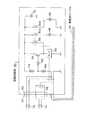
(起動回路部の構成)
図5は、図4の消火装置30の中央の区画に配置した起動回路部60の実施形態を示した回路図である。図5に示すように、起動回路部60は、蓄電装置10内に布線した熱感知ケーブル64を接続すると共に、プラグ63及びコネクタ62を介して消火起動指示信号を入力する信号線72、及び消火起動検出信号を出力する信号線74を接続している。なお、消火起動指示信号を入力する信号線72は通常監視状態で開放状態にあり、消火起動指示信号を入力する場合は、短絡状態となる。(Configuration of startup circuit)
FIG. 5 is a circuit diagram showing an embodiment of the
起動回路部60には、トランジスタ84、リレー86、抵抗78,80,82を備えたヒータ駆動回路及び電池電源76を設ける。電池電源76は釦電池などの一次電池であり、外部からの電源供給を不要としている。 The starting
トランジスタ84は、抵抗78,80の分圧電圧を、抵抗82を介してベースに印加しており、熱感知ケーブル64には抵抗78,80を介して電池電源76からの電源電圧を常時、印加している。ここで、通常監視状態でトランジスタ84はオフであり、また熱感知ケーブル64の一方の信号線には電源電圧のみが印加されるだけで電流は流れておらず、起動回路部60の消費電量は漏れ電流などに起因した極く僅かな消費電流だけであり、電池電源76として一次電池を使用しても、必要にして十分な電池寿命を確保可能である。 The
トランジスタ84はPNPトランジスタであり、コレクタ側に負荷としてリレー86を接続しており、通常監視状態にあっては、熱感知ケーブル64は2本の信号線のビニールなどによる絶縁被覆で開放状態にあり、電池電源76から電流は流れず、トランジスタ84はエミッタ,ベース間の電圧が0ボルトであることからオフ状態となっている。 The
リレー86は、その常開リレー接点90a,90bを介して一対のヒータ48を接続している。また、リレー86の常開リレー接点88をトランジスタ84のエミッタ・コレクタ間に接続し、ラッチ回路を形成している。更に、コネクタ62の端子に消火起動検出信号を出力するためのリレー接点92を接続している。
The
蓄電装置10に収納したリチウムイオン電池20の熱暴走で作動した安全弁25から噴き出す電解液の火炎の熱を受けて熱感知ケーブル64の絶縁被覆であるビニールが溶け、2本の信号線が接触状態になると、抵抗78、80を介して熱感知ケーブル64に電流が流れる。このため、抵抗78に生ずる電圧によりトランジスタ84のエミッタ・ベース間にバイアス電圧が加わり、これによってトランジスタ84がオンしてリレー86を作動する。 The insulation coating of the
リレー86が作動すると常開リレー接点90a,90bが閉じ、一対のヒータ48のそれぞれに通電し、ヒータ48の通電による加熱で点火剤46を起爆し、これに伴い固形消火剤42に点火して燃焼することで消火用エアロゾルを発生して、爆風及び消火用エアロゾルにより雲母粉末剤34を攪拌加圧し、放出管36から蓄電装置10内に消火用エアロと共に雲母粉末剤34を放出させる。
When the
またリレー86の作動により常開リレー接点88が閉じることで、リレー86を作動状態にラッチし、これによって、熱感知ケーブル64の短絡状態の変動による誤動作を防ぐようにしている。
Further, when thenormally
更に、リレー接点92が閉じることで、信号線74を介して外部に対し消火動作が行われたことを示す消火起動検出信号を出力し、必要に応じて消火起動検出信号を受信した外部装置で電池火災に対する消火装置の起動を表示して知らせる。 Further, when the
一方、外部装置側から必要に応じて消火起動指示信号が入力されると、信号線72は短絡状態となり、熱感知ケーブル64により火災検知した場合と同様に、抵抗78、80を介して信号線72に電流が流れてトランジスタ84がオンし、リレー86の作動で常開リレー接点90a,90bが閉じてヒータ48に通電し、点火剤46を起爆して固形消火剤42を燃焼することで消火用エアロゾルを発生して、爆風及び消火用エアロゾルにより雲母粉末剤34を攪拌加圧し、放出管36から蓄電装置10内に消火用エアロゾルと共に雲母粉末剤34を放出させる。
On the other hand, when a fire extinguishing start instruction signal is input as necessary from the external device side, the
(消火装置の動作)
図6は消火装置30の動作を示した説明図である。図6において、蓄電装置10に収納しているリチウムイオン電池20のいずれかが熱暴走を起こして電池温度が著しく上昇し、圧力上昇により安全弁25が作動(破裂)し、充填している非水電解液が発火して火炎を激しく噴き出す火災を起こした場合、消火装置30の起動回路部60が蓄電装置10内に布設した熱感知ケーブル64の火災による短絡状態を検出し、ヒータ48に通電加熱して点火剤46を起爆し、これに伴い固形消火剤42に点火して燃焼することで消火用エアロゾルを発生する。
(Operation of fire extinguishing device)
FIG. 6 is an explanatory view showing the operation of the
点火剤46の起爆で発生した爆風は、火炎噴出防止部材50を介して噴き出した後、仕切部材52のノズル孔54の封止部材56を破って爆風を噴出し、これにより絶縁剤収納部32に充填している雲母粉末剤34を攪拌し、引き続き絶縁剤収納部32には固形消火剤42の燃焼で発生した消火用エアロゾルが送り込まれる。絶縁剤収納部32の内圧が所定の圧力に達すると放出管36を閉鎖している封止部材38が破れ、雲母粉末剤34が消火用エアロゾルと共に放出管36を通って蓄電装置10内の空き空間に放出され、短時間に空き空間に充満する。
The blast generated by the initiation of the
このため熱暴走を起こしたリチウムイオン電池20から噴き出している電解液の火炎を、放出した雲母粉末剤34で包み込むと共に霧化した電解液を吸着し、雲母粉末剤34は消火砂として機能して、リチウムイオン電池20から噴き出している火炎を消火抑制する。また固形消火剤42の燃焼により発生した消火用エアロゾルも蓄電装置10内に継続的に放出され、リチウムイオン電池20から噴き出している火炎を消火抑制する。 For this reason, the flame of the electrolyte sprayed from the
一方、蓄電装置10内に放出した雲母粉末剤34は、熱暴走を起こしたリチウムイオン電池20から噴出している霧化した電解液と混合し、雲母粉末剤34と混合した電解液は導電性が低下して絶縁抵抗が高くなり、雲母粉末剤34と混合した電解液が他のリチウムイオン電池20の電極端子22間やバスバー24間に付着しても、導電性が低下したことで短絡電流を抑制し、外部短絡による連鎖的な熱暴走を防止可能とする。 On the other hand, the
[不活性ガスを加圧源に用いた消火装置]
(消火装置の構成)
図7は不活性ガスを加圧源とした図1の消火装置及び蓄電装置の縦断面を示した断面図、図8は図7の消火装置の蓋を外して装置本体内を示した平面図である。[Fire extinguishing equipment using inert gas as a pressurized source]
(Configuration of fire extinguishing device)
FIG. 7 is a cross-sectional view showing a longitudinal section of the fire extinguishing apparatus and power storage apparatus of FIG. 1 using an inert gas as a pressurizing source, and FIG. It is.
図7及び図8に示すように、本実施形態の消火装置30は、加圧手段に、ガス収納部となるボンベ94、ガス放出ヘッド98、ガス放出弁96を設けている。ボンベ94には不活性ガスとして窒素ガス又は二酸化炭素ガスを加圧充填している。 As shown in FIGS. 7 and 8, the
ガス放出ヘッド98はボンベ94に加圧充填した不活性ガスを絶縁剤収納部32に放出する。ガス放出弁96はボンベ94とガス放出ヘッド98の間に設けられ、通常は閉鎖しており、起動回路部60から開制御信号を受けた場合に開動作し、ボンベ94に加圧充填している不活性ガスをガス放出ヘッド98から絶縁剤収納部32に放出し、雲母粉末剤34を加圧し、放出管36から蓄電装置10内へ放出させる。
The
また、起動回路部60を配置した中央の区画には、蓄電装置10内に連通する複数の連通穴100を開口し、更に外部に連通する排気口102を開口し、排気口102の内側にはフィルタ104を配置している。 In addition, a plurality of
起動回路部60は図5と基本的に同じになるが、常開リレー接点90a,90bの負荷として、ヒータ48に代えてガス放出弁96の駆動部を設け、リレー接点90a,90bを閉じることで開制御信号を出力するようにしている。
The starting
それ以外の構成は、図1乃至図5の固形消火剤を加圧源に用いた場合と同様になることから、説明を省略する。 Other configurations are the same as those in the case where the solid fire extinguishing agent shown in FIGS.
(消火装置の動作)
図7及び図8に示した消火装置30の動作を説明すると次のようになる。蓄電装置10に収納しているリチウムイオン電池20のいずれかが、熱暴走して安全弁25が作動(破裂)し、充填している非水電解液が発火して火炎を激しく噴き出す火災を起こした場合、消火装置30の起動回路部60が蓄電装置10内に布設した熱感知ケーブル64の火災による短絡状態を検出し、ガス放出弁96を開動作し、ボンベ94に加圧充填している不活性ガスをガス放出ヘッド98から絶縁剤収納部32へ放出し、そこに充填している雲母粉末剤34を攪拌加圧する。
(Operation of fire extinguishing device)
The operation of the
絶縁剤収納部32の内圧が所定の圧力に達すると放出管36を閉鎖している封止部材38が破れ、雲母粉末剤34が不活性ガスと共に放出管36を通って蓄電装置10内の空き空間に放出され、短時間に空き空間に充満する。 When the internal pressure of the insulating
このため熱暴走を起こしたリチウムイオン電池20から噴き出している着火した電解液の火炎を、放出した雲母粉末剤34で包み込むと共に霧化した電解液を吸着し、雲母粉末剤34は消火砂として機能して、リチウムイオン電池20から噴き出している火炎を消火抑制し、更に、ボンベ94から放出した不活性ガスによっても、リチウムイオン電池20から噴き出している火炎を消火抑制する。 For this reason, the flame of the ignited electrolyte discharged from the
一方、蓄電装置10内に放出した雲母粉末剤34は、熱暴走を起こしたリチウムイオン電池20から噴出している霧化した電解液と混合して絶縁抵抗が高くなり、電解液が他のリチウムイオン電池20の電極端子22間やバスバー24間に付着した場合の外部短絡による連鎖的な熱暴走を防止可能とする。 On the other hand, the
また、消火装置30から雲母粉末剤34を不活性ガスによる加圧で蓄電装置10に放出した場合、蓄電装置10の内部圧力が不活性ガスにより増加するが、蓄電装置10内は連通穴100を介して消火装置30の中央の区画に連通し、更にフィルタ104を介して排気口102から外部に連通しているため、蓄電装置10内の内圧は所定圧力を超えることがなく、蓄電装置10の破裂は回避できる。また蓄電装置10から外部に排出される雰囲気はフィルタ104を通ることで、霧化した電解液、可燃性ガス、放出した雲母粉末剤などが除去され、外部への排出を抑制する。
In addition, when the
[本発明の変形例]
(消火装置の配置)
上記の実施形態にあっては、消火装置を蓄電装置における収納容器蓋の上に配置した場合を例にとっているが、蓄電装置の収納容器蓋の内側に配置してもよい。この場合、消火装置の底板に蓄電装置の容器収納蓋の構造を設ければ良い。[Modification of the present invention]
(Arrangement of fire extinguishing equipment)
In the above embodiment, the case where the fire extinguishing device is arranged on the storage container lid in the power storage device is taken as an example, but it may be arranged inside the storage container lid of the power storage device. In this case, the container storage lid structure of the power storage device may be provided on the bottom plate of the fire extinguishing device.
(絶縁粉末剤)
上記の実施形態は、粉末絶縁剤して雲母粉末剤を使用したが、これ以外に高い絶縁性と耐熱性をもつセラミックス系やガラス系など適宜の粉末絶縁剤を使用しても良い。(Insulating powder)
In the above embodiment, a mica powder agent is used as a powder insulating agent. However, an appropriate powder insulating agent such as a ceramic type or a glass type having high insulation and heat resistance may be used.
(消火装置の構造)
上記の実施形態にあっては、消火装置を3区画に分け、その内の2区画に絶縁剤収納手段と加圧手段を別々に設けて二重化することで、信頼性を高めているが、消火装置を2区画に分け、そのうちの1区画に絶縁剤収納手段と加圧手段を設けた構造としても良い。(Structure of fire extinguishing equipment)
In the above embodiment, the fire extinguishing apparatus is divided into three sections, and the reliability is improved by providing the insulating container storing means and the pressurizing means separately in the two sections and duplicating them. The apparatus may be divided into two sections, and one of the sections may be provided with an insulating material storing means and a pressurizing means.
(消火装置の電源)
また、上記の実施形態にあっては、消火装置に一次電池を用いた電池電源を内蔵して起動回路部を動作しているが、蓄電装置の収納容器内に収納しているリチウムイオン電池(二次電池)から電源を供給するようにしても良い。(Fire extinguishing device power supply)
In the above embodiment, the battery circuit power source using the primary battery is incorporated in the fire extinguisher and the starter circuit unit is operated. However, the lithium ion battery (in the storage container of the power storage device) ( A power source may be supplied from the secondary battery.
(火災検知部)
また、上記の実施形態は、リチウムイオン電池の異常に伴う火災を検知する火災検知部として熱感知ケーブルを設けているが、これ以外に、熱電対、サーミスタ等の温度センサ、レーザパルス光を入射した場合の後方散乱光の強度から温度測定する光ファイバーセンサなどの適宜の火災検知部を設けても良い。(Fire detection part)
In the above embodiment, a heat detection cable is provided as a fire detection unit for detecting a fire due to an abnormality of the lithium ion battery. In addition to this, a temperature sensor such as a thermocouple or a thermistor, laser pulse light is incident. An appropriate fire detection unit such as an optical fiber sensor for measuring the temperature from the intensity of the backscattered light may be provided.
(消火装置の用途)
また、上記の実施形態は、航空機の蓄電装置を例にとるものであったが、自動車用、住宅用のリチウムイオン電池を収納した蓄電装置の消火装置として同様に設けることができ更に、それ以外の適宜の機器、装置、設備、施設に設置されるリチウムイオン電池を用いた蓄電装置の消火装置についても、同様に適用可能である。(Use of fire extinguishing equipment)
In addition, the above embodiment is an example of an aircraft power storage device, but it can be similarly provided as a fire extinguishing device for a power storage device containing lithium-ion batteries for automobiles and houses. The present invention can be similarly applied to a fire extinguishing device for a power storage device using a lithium ion battery installed in any appropriate device, apparatus, facility, or facility.
(その他)
また、本発明は上記の実施形態に限定されず、その目的と利点を損なうことのない適宜の変形を含み、更に上記の実施形態に示した数値による限定は受けない。(Other)
The present invention is not limited to the above-described embodiment, includes appropriate modifications without impairing the object and advantages thereof, and is not limited by the numerical values shown in the above-described embodiment.
10:蓄電装置
20:リチウムイオン電池
25:安全弁
30:消火装置
32:絶縁剤収納部
34:雲母粉末剤
36:放出管
38,56:封止部材
40:固形消火剤収納部
42:固形消火剤
46:点火剤
48:ヒータ
50:火炎噴出防止部材
60:起動回路部
64:熱感知ケーブル
94:ボンベ
96:ガス放出弁
98:ガス放出ヘッド10: Power storage device 20: Lithium ion battery 25: Safety valve 30: Fire extinguishing device 32: Insulating agent storage part 34: Mica powder agent 36:
Claims (8)
Translated fromJapanese前記蓄電装置の内部空き空間に対応した所定量の粉末絶縁剤が充填された絶縁剤収納手段と、
前記絶縁剤収納手段に充填された前記粉末絶縁剤を加圧する加圧手段と、
前記リチウムイオン電池の異常に伴う火災を検出した場合に、前記加圧手段の作動により前記絶縁剤収納手段に充填された粉末絶縁剤を加圧し、前記蓄電装置内に前記粉末絶縁剤を消火砂として放出させる消火制御手段と、
を備え、
前記加圧手段は、
一端を前記絶縁剤収納手段内に開口し、他端を前記蓄電装置内に開口する放出管を備え、固形消化剤の燃焼により前記粉末絶縁剤を加圧することを特徴とする消火装置。
In a fire extinguishing device provided in a power storage device containing a plurality of lithium ion batteries,
Insulating agent storage means filled with a predetermined amount of powder insulating agent corresponding to the internal empty space of the power storage device;
A pressurizing unit that pressurizes the powder insulating agent filled in the insulating agent storage unit;
When a fire associated with an abnormality of the lithium ion battery is detected, the powder insulating agent filled in the insulating material storing means is pressurized by the operation of the pressurizing means, and the powder insulating agent is extinguished in the power storage device. Fire extinguishing control means to be released as,
With
The pressurizing means is
A fire extinguishing apparatuscomprising a discharge pipe having one end opened in the insulating agent storage means and the other end opened in the power storage device, andpressurizing the powder insulating agent by burning solid digestive agent .
一端を閉鎖すると共に他端を前記絶縁剤収納手段側に開口し、燃焼により消火用エアロゾルを発生する固形消火剤が収納された固形消火剤収納部と、A solid fire extinguisher storage section containing a solid fire extinguisher that closes one end and opens the other end to the insulating agent storage means side and generates a fire extinguishing aerosol by combustion;
前記固形消火剤収納部の開口側に配置された火炎噴出防止部材と、A flame ejection preventing member disposed on the opening side of the solid fire extinguishing agent storage unit;
を備えたことを特徴とする消火装置。A fire extinguisher characterized by comprising:
2. The fire extinguishing apparatus according to claim 1, wherein the pressurizing means includes a sealing member that seals the discharge pipe and is broken by pressurization of the powder insulating agent.
前記火災を検出した場合に、前記加圧手段を作動させると共に外部に消火起動検出信号を出力する起動回路部と、
前記起動回路部との間を信号線で接続したコネクタと、
前記コネクタに着脱自在に設けられ、前記消火起動検出信号を外部に出力する信号線を前記コネクタに接続するプラグと、
を備えたことを特徴とする消火装置。
The fire extinguishing apparatus according to claim 1, wherein the fire extinguishing control means includes:
An activation circuit unit that activates the pressurizing means and outputs a fire extinguishing activation detection signal to the outside when the fire is detected;
A connector connected with a signal line between the starter circuit unit,
A plug that is detachably provided on the connector and that connects the signal line for outputting the fire-extinguishing start detection signal to the connector;
A fire extinguisher characterized by comprising:
前記起動回路部は、ヒータの通電加熱により前記固形消火剤を燃焼させることを特徴とする消火装置。
The fire extinguishing apparatus according to claim4,
The fire-extinguishing apparatus, wherein the starting circuit unit burns the solid fire extinguisher by energization heating ofa heater.
2. The fire extinguishing apparatus according to claim 1, wherein the fire extinguishing control means includes a heat sensing cable that contacts a pair of signal wires in a short-circuited state by melting the insulating coating when receiving heat from the fire. Special fire extinguishing device.
7. The fire extinguishing apparatus according to claim 6, wherein the heat sensing cable is laid so as to pass in the vicinity of safety valves provided in all lithium ion batteries housed in the power storage device.
Priority Applications (1)
| Application Number | Priority Date | Filing Date | Title |
|---|---|---|---|
| JP2013029564AJP6189603B2 (en) | 2013-02-19 | 2013-02-19 | Fire extinguisher |
Applications Claiming Priority (1)
| Application Number | Priority Date | Filing Date | Title |
|---|---|---|---|
| JP2013029564AJP6189603B2 (en) | 2013-02-19 | 2013-02-19 | Fire extinguisher |
Publications (2)
| Publication Number | Publication Date |
|---|---|
| JP2014158508A JP2014158508A (en) | 2014-09-04 |
| JP6189603B2true JP6189603B2 (en) | 2017-08-30 |
Family
ID=51610767
Family Applications (1)
| Application Number | Title | Priority Date | Filing Date |
|---|---|---|---|
| JP2013029564AActiveJP6189603B2 (en) | 2013-02-19 | 2013-02-19 | Fire extinguisher |
Country Status (1)
| Country | Link |
|---|---|
| JP (1) | JP6189603B2 (en) |
Cited By (2)
| Publication number | Priority date | Publication date | Assignee | Title |
|---|---|---|---|---|
| CN111632311A (en)* | 2020-04-16 | 2020-09-08 | 杭州伯坦科技工程有限公司 | Fire fighting box for power battery of electric automobile and fire extinguishing method |
| IT202200019338A1 (en)* | 2022-09-21 | 2024-03-21 | Ferrari Spa | ELECTRIC POWERED VEHICLE EQUIPPED WITH A FIRE-FIGHTING SYSTEM |
Families Citing this family (65)
| Publication number | Priority date | Publication date | Assignee | Title |
|---|---|---|---|---|
| JP6279834B2 (en)* | 2013-02-20 | 2018-02-14 | ホーチキ株式会社 | Power storage device and moving body or facility using the same |
| US9853267B2 (en)* | 2014-02-03 | 2017-12-26 | Ursatech Ltd. | Intumescent battery housing |
| CN105169586A (en)* | 2015-09-29 | 2015-12-23 | 上海博笃实业有限公司 | Fire extinguishing system |
| JP6694285B2 (en)* | 2016-02-02 | 2020-05-13 | 古河電池株式会社 | Battery leakage absorption structure |
| US20170237054A1 (en)* | 2016-02-16 | 2017-08-17 | Thomas Michael Mast | System and method for a reinforced container associated with battery handling |
| US10173087B2 (en)* | 2016-05-26 | 2019-01-08 | The Boeing Company | Fire suppression apparatuses and methods for suppressing a fire with an object |
| JP6586524B2 (en)* | 2016-06-10 | 2019-10-02 | ヤマトプロテック株式会社 | Electrochemical equipment using aerosol fire extinguishing device |
| CN106693234B (en)* | 2017-02-07 | 2022-04-19 | 上海蔚来汽车有限公司 | Battery isolation device, charging and swapping station with the same, and battery isolation method |
| CN107310411A (en)* | 2017-06-16 | 2017-11-03 | 明森智能消防装备(江苏)有限公司 | A kind of removable safe charging cabin |
| CN107394064A (en)* | 2017-07-12 | 2017-11-24 | 浙江谷神能源科技股份有限公司 | Lithium battery safety box |
| KR102050140B1 (en)* | 2017-12-12 | 2019-11-28 | 주식회사 파이어푸로코리아 | Hybrid extinguishing system for fire suppression of bus engine room |
| CN108166779B (en)* | 2017-12-19 | 2020-08-21 | 广东立佳实业有限公司 | Environmental bin for power battery |
| KR102202666B1 (en)* | 2018-07-18 | 2021-01-13 | (주)대건테크 | Fire detection system for flammable metal powder 3D printer |
| CN108711660B (en)* | 2018-07-27 | 2024-07-16 | 清华大学 | Lithium ion battery |
| CN109552080B (en)* | 2018-12-21 | 2024-01-26 | 北京科易动力科技有限公司 | Vehicle with a vehicle body having a vehicle body support |
| CN109830769B (en)* | 2019-01-25 | 2021-04-30 | 惠州市匠心照明科技有限公司 | Polymer lithium ion battery |
| CN209822756U (en)* | 2019-04-30 | 2019-12-20 | 宁德时代新能源科技股份有限公司 | Battery module and battery pack |
| KR102199307B1 (en)* | 2019-06-28 | 2021-01-07 | 산일전기 주식회사 | Energy Storage System Device with Fire Extinguisher |
| JP7381987B2 (en)* | 2019-07-04 | 2023-11-16 | 三菱自動車工業株式会社 | Battery pack abnormality detection device |
| CN110393876B (en)* | 2019-08-05 | 2024-05-31 | 清华大学 | Lithium-ion battery fire protection device |
| JP7315676B2 (en)* | 2019-08-06 | 2023-07-26 | 日本碍子株式会社 | battery module |
| KR102866645B1 (en)* | 2019-08-08 | 2025-09-29 | 주식회사 엘지에너지솔루션 | Battery Pack Having Fire Extinguishing Unit |
| CN211828872U (en)* | 2019-09-09 | 2020-10-30 | 福建易动力电子科技股份有限公司 | Mining explosion-proof power supply device |
| CN110706857B (en)* | 2019-10-16 | 2020-11-20 | 扬州市红旗电缆制造有限公司 | High ageing resistance does not have steamed low fire-retardant marine frock spare special cable of cigarette |
| CN111068209B (en)* | 2020-01-07 | 2020-12-22 | 扬州瑞顺投资咨询有限公司 | Short-circuit open fire prevention foam covering device |
| US11211669B2 (en)* | 2020-02-07 | 2021-12-28 | Baidu Usa Llc | Battery backup unit (BBU) shelf with a fire extinguishing system |
| CN111192981A (en)* | 2020-02-27 | 2020-05-22 | 中国科学技术大学 | Lithium battery and fire extinguishing device for lithium battery |
| CN111477992B (en)* | 2020-03-10 | 2022-10-04 | 安徽潜川动力锂电科技有限公司 | An explosion-proof protective shell based on lithium iron phosphate battery |
| KR102188110B1 (en)* | 2020-04-10 | 2020-12-07 | 인선모터스 주식회사 | Battery storage apparatus for disassembling system of electric vehicle |
| KR20210141806A (en)* | 2020-05-13 | 2021-11-23 | 주식회사 엘지에너지솔루션 | Battery pack containing fire suppression means |
| CN112018460B (en)* | 2020-07-17 | 2021-09-03 | 清华大学 | Method for regulating and controlling thermal failure chemical reaction of battery |
| CN112018390B (en)* | 2020-07-17 | 2021-09-14 | 清华大学 | Sandwich electrode and battery |
| CN112018459B (en)* | 2020-07-17 | 2021-09-14 | 清华大学 | Battery system thermal failure diffusion inhibition structure and determination method thereof, and battery system |
| CN111864284B (en)* | 2020-08-11 | 2024-04-02 | 东北大学 | An experimental device and method for ultra-fine water mist fire extinguishing of enclosed lithium-ion battery packs |
| CN111991729B (en)* | 2020-09-11 | 2022-03-04 | 中车大同电力机车有限公司 | Power supply fire extinguishing device and locomotive |
| CN112402841A (en)* | 2020-11-23 | 2021-02-26 | 杭州叁沃智能科技有限公司 | Fire extinguishing device for electric meter box |
| CN112421110B (en)* | 2020-11-26 | 2022-07-01 | 扬州大学 | Electrolyte with built-in fire extinguishing material and operation process thereof |
| US11541258B2 (en) | 2020-12-23 | 2023-01-03 | Yantai Chungway New Energy Technology Co., Ltd. | Fire extinguishing system for battery pack |
| KR20220100450A (en)* | 2021-01-08 | 2022-07-15 | 주식회사 엘지에너지솔루션 | Battery pack and vehicle including the same |
| CN113262420B (en)* | 2021-05-28 | 2022-06-03 | 张永前 | Fire extinguishing agent for lithium battery and preparation method and application thereof |
| CN113499555A (en)* | 2021-06-16 | 2021-10-15 | 国网山东省电力公司济南供电公司 | Electric power fire prevention protection device for power construction |
| KR102380307B1 (en)* | 2021-06-23 | 2022-03-29 | 장가익 | Apparatus for preventing fire spread of cable tray for fire fighting installed in apartment buildings |
| CN113694433A (en)* | 2021-07-26 | 2021-11-26 | 岚图汽车科技有限公司 | Power battery fire extinguishing system and power battery fire extinguishing method |
| CN113629349A (en)* | 2021-08-03 | 2021-11-09 | 陕西奥林波斯电力能源有限责任公司 | A safety structure for a large-capacity battery |
| KR102423957B1 (en)* | 2021-08-24 | 2022-07-26 | 주식회사 진명엔지니어링건축사사무소 | Apparatus of protection fire spread using cable support tray |
| KR102864398B1 (en)* | 2021-08-25 | 2025-09-24 | 주식회사 엘지에너지솔루션 | Secondary battery and battery module containing the same |
| DE102021127617A1 (en)* | 2021-10-25 | 2023-04-27 | Audi Aktiengesellschaft | Battery arrangement with a quenching device and motor vehicle |
| EP4297145A4 (en)* | 2021-10-29 | 2024-11-20 | LG Energy Solution, Ltd. | BATTERY PACK WITH IMPROVED SAFETY |
| CN114272532B (en)* | 2021-12-31 | 2022-12-27 | 江苏天瑞变压器有限公司 | Transformer operation monitoring device |
| CN114832258B (en)* | 2022-03-28 | 2023-05-26 | 江苏城乡建设职业学院 | Microcapsule fire extinguishing device for super capacitor module |
| JP7722270B2 (en) | 2022-06-01 | 2025-08-13 | トヨタ自動車株式会社 | High voltage equipment and high voltage equipment safety systems |
| CN114976206B (en)* | 2022-06-02 | 2023-11-24 | 江苏阿拉丁高温材料有限公司 | Liquid leakage flame-retardant structure of lithium ion battery pack |
| CN117916929A (en)* | 2022-06-10 | 2024-04-19 | 株式会社 Lg新能源 | Battery pack and vehicle including the battery pack |
| CN115445120B (en)* | 2022-09-06 | 2023-03-31 | 浙江杭消消防设备有限公司 | Automatic positioning fire extinguishing system of energy storage station |
| CN115621578B (en) | 2022-11-15 | 2023-03-31 | 深圳海润新能源科技有限公司 | Linkage control system and method for battery cluster |
| CN115764127A (en)* | 2022-11-23 | 2023-03-07 | 江苏耀宁新能源创新科技有限公司 | a battery box |
| FR3147907B1 (en)* | 2023-04-14 | 2025-02-28 | Psa Automobiles Sa | MOTOR VEHICLE BATTERY COMPRISING A CASING DESIGNED TO STOP A FIRE |
| DE102023120628B4 (en)* | 2023-08-03 | 2025-07-17 | Deutsches Zentrum für Luft- und Raumfahrt e.V. | Method and device for extinguishing a fire on an object |
| CN117175033B (en)* | 2023-09-05 | 2024-05-17 | 中国矿业大学(北京) | An active explosion suppression device for lithium-ion batteries |
| CN117199623B (en)* | 2023-11-03 | 2024-02-09 | 新乡市镇华电力科技有限公司 | Phase-change electric energy dynamic storage device |
| CN117458042B (en)* | 2023-12-25 | 2024-05-14 | 长春众升科技发展有限公司 | Battery placement bin for new energy automobile |
| CN118367261A (en)* | 2024-04-18 | 2024-07-19 | 江苏中能汇宏经济发展有限公司 | Energy storage integrated cabinet and fixing method thereof |
| KR102781768B1 (en)* | 2024-07-18 | 2025-03-17 | 립스 주식회사 | Fire protection system including air purification function |
| KR102781770B1 (en)* | 2024-08-19 | 2025-03-18 | 립스 주식회사 | Battery storage device |
| CN119911144A (en)* | 2025-04-07 | 2025-05-02 | 樊氏科技发展股份有限公司 | A combined new energy charging pile |
Family Cites Families (12)
| Publication number | Priority date | Publication date | Assignee | Title |
|---|---|---|---|---|
| JP3037506B2 (en)* | 1992-05-25 | 2000-04-24 | 日本碍子株式会社 | Fire extinguishing method and apparatus for sodium-sulfur battery |
| JPH06269509A (en)* | 1993-03-17 | 1994-09-27 | Ngk Insulators Ltd | Sprikler for fire extinguishing agents |
| JPH06290813A (en)* | 1993-04-01 | 1994-10-18 | Hitachi Ltd | Assembly type non-aqueous secondary battery |
| US5423384A (en)* | 1993-06-24 | 1995-06-13 | Olin Corporation | Apparatus for suppressing a fire |
| JP2718444B2 (en)* | 1994-10-24 | 1998-02-25 | 株式会社科防総合研究所 | Fire extinguisher |
| JPH11219732A (en)* | 1998-02-03 | 1999-08-10 | Toyo System Kk | Charging and discharging apparatus for battery |
| JP2001257006A (en)* | 2000-03-13 | 2001-09-21 | Japan Storage Battery Co Ltd | Battery system, industrial system equipped with battery system and mobile structure |
| JP5080230B2 (en)* | 2007-12-13 | 2012-11-21 | ホーチキ株式会社 | Smoke extinguishing device |
| JP2010097836A (en)* | 2008-10-17 | 2010-04-30 | Panasonic Corp | Battery pack, electronic equipment using it as power source, and battery pack case |
| JP5618641B2 (en)* | 2010-06-07 | 2014-11-05 | 能美防災株式会社 | Fire extinguisher |
| DE102011009696A1 (en)* | 2011-01-28 | 2012-08-02 | Li-Tec Battery Gmbh | Transport device for electrochemical energy storage devices |
| KR101424704B1 (en)* | 2011-09-08 | 2014-07-31 | 주식회사 엘지화학 | Fire suppression apparatus for battery pack |
- 2013
- 2013-02-19JPJP2013029564Apatent/JP6189603B2/enactiveActive
Cited By (2)
| Publication number | Priority date | Publication date | Assignee | Title |
|---|---|---|---|---|
| CN111632311A (en)* | 2020-04-16 | 2020-09-08 | 杭州伯坦科技工程有限公司 | Fire fighting box for power battery of electric automobile and fire extinguishing method |
| IT202200019338A1 (en)* | 2022-09-21 | 2024-03-21 | Ferrari Spa | ELECTRIC POWERED VEHICLE EQUIPPED WITH A FIRE-FIGHTING SYSTEM |
Also Published As
| Publication number | Publication date |
|---|---|
| JP2014158508A (en) | 2014-09-04 |
Similar Documents
| Publication | Publication Date | Title |
|---|---|---|
| JP6189603B2 (en) | Fire extinguisher | |
| JP6042734B2 (en) | Fire extinguisher | |
| JP6279834B2 (en) | Power storage device and moving body or facility using the same | |
| JP6080201B2 (en) | Fire extinguishing apparatus and aging method using the same | |
| JP6103856B2 (en) | Fire extinguishing system for electric vehicles | |
| JP2017060805A (en) | Fire extinguishing system for electric vehicles | |
| JP2014036714A (en) | Fire-extinguishing system for electric vehicle | |
| JP6017221B2 (en) | Fire extinguishing system for electric vehicles | |
| JP6231266B2 (en) | Fire extinguishing system for electric vehicles | |
| JP6103887B2 (en) | Power storage system | |
| KR102494248B1 (en) | Battery Fire Prevention System for Electric Vehicles | |
| CN221126070U (en) | Box, battery and electric equipment | |
| JP5993271B2 (en) | Power storage device | |
| CN112103444B (en) | Battery, electric equipment and manufacturing method of battery | |
| JP2017004959A (en) | Power storage device | |
| KR20160032843A (en) | Battery module of improved safety and battery pack containing the same | |
| JP7714785B2 (en) | Battery pack, energy storage device including the battery pack, and automobile | |
| KR101332464B1 (en) | Safety evaluation test apparatus | |
| JP7453257B2 (en) | A battery module, a battery rack including the battery module, and a power storage device including the battery rack | |
| CN117477078A (en) | Battery pack for electric vehicle and electric vehicle | |
| CN216536631U (en) | Power battery and two-wheeled electric vehicle | |
| JP2014033825A (en) | Fire-extinguishing system for electric vehicle | |
| JP6042687B2 (en) | Solar power system | |
| CN212067519U (en) | Safety fire extinguishing device for vehicle energy storage battery | |
| CN210409296U (en) | Safe microminiature extinguishing device |
Legal Events
| Date | Code | Title | Description |
|---|---|---|---|
| A621 | Written request for application examination | Free format text:JAPANESE INTERMEDIATE CODE: A621 Effective date:20151119 | |
| A977 | Report on retrieval | Free format text:JAPANESE INTERMEDIATE CODE: A971007 Effective date:20160805 | |
| A131 | Notification of reasons for refusal | Free format text:JAPANESE INTERMEDIATE CODE: A131 Effective date:20160810 | |
| A521 | Request for written amendment filed | Free format text:JAPANESE INTERMEDIATE CODE: A523 Effective date:20161007 | |
| A131 | Notification of reasons for refusal | Free format text:JAPANESE INTERMEDIATE CODE: A131 Effective date:20170208 | |
| A521 | Request for written amendment filed | Free format text:JAPANESE INTERMEDIATE CODE: A523 Effective date:20170328 | |
| TRDD | Decision of grant or rejection written | ||
| A01 | Written decision to grant a patent or to grant a registration (utility model) | Free format text:JAPANESE INTERMEDIATE CODE: A01 Effective date:20170712 | |
| A61 | First payment of annual fees (during grant procedure) | Free format text:JAPANESE INTERMEDIATE CODE: A61 Effective date:20170803 | |
| R150 | Certificate of patent or registration of utility model | Ref document number:6189603 Country of ref document:JP Free format text:JAPANESE INTERMEDIATE CODE: R150 |