Movatterモバイル変換


[0]ホーム

URL:


JP6189497B1 - Method for providing virtual space, method for providing virtual experience, program, and recording medium - Google Patents

Method for providing virtual space, method for providing virtual experience, program, and recording medium
Download PDF

Info

Publication number
JP6189497B1
JP6189497B1JP2016142762AJP2016142762AJP6189497B1JP 6189497 B1JP6189497 B1JP 6189497B1JP 2016142762 AJP2016142762 AJP 2016142762AJP 2016142762 AJP2016142762 AJP 2016142762AJP 6189497 B1JP6189497 B1JP 6189497B1
Authority
JP
Japan
Prior art keywords
virtual
virtual object
hmd
user
hand
Prior art date
Legal status (The legal status is an assumption and is not a legal conclusion. Google has not performed a legal analysis and makes no representation as to the accuracy of the status listed.)
Active
Application number
JP2016142762A
Other languages
Japanese (ja)
Other versions
JP2018013938A (en
Inventor
集平 寺畑
集平 寺畑
Current Assignee (The listed assignees may be inaccurate. Google has not performed a legal analysis and makes no representation or warranty as to the accuracy of the list.)
Colopl Inc
Original Assignee
Colopl Inc
Priority date (The priority date is an assumption and is not a legal conclusion. Google has not performed a legal analysis and makes no representation as to the accuracy of the date listed.)
Filing date
Publication date
Application filed by Colopl IncfiledCriticalColopl Inc
Priority to JP2016142762ApriorityCriticalpatent/JP6189497B1/en
Priority to US15/654,652prioritypatent/US10198855B2/en
Priority to CN202110157743.XAprioritypatent/CN112783328B/en
Priority to CN201780038446.5Aprioritypatent/CN109313511B/en
Priority to PCT/JP2017/026185prioritypatent/WO2018016553A1/en
Application grantedgrantedCritical
Publication of JP6189497B1publicationCriticalpatent/JP6189497B1/en
Publication of JP2018013938ApublicationCriticalpatent/JP2018013938A/en
Priority to US16/223,012prioritypatent/US10776991B2/en
Activelegal-statusCriticalCurrent
Anticipated expirationlegal-statusCritical

Links

Images

Landscapes

Abstract

Translated fromJapanese

【課題】直感的な操作で仮想オブジェクトと接触することが可能な仮想体験を提供する。
【解決手段】制御回路部は、操作対象オブジェクトに付随する付随オブジェクトにおいて第1仮想オブジェクトの判定領域に含まれる部分が、第2仮想オブジェクトの判定領域に含まれる部分よりも大きい場合、操作対象オブジェクトが第1仮想オブジェクトに接触したと判定する。
【選択図】図20
A virtual experience capable of contacting a virtual object by an intuitive operation is provided.
When a portion included in the determination area of the first virtual object is larger than a portion included in the determination area of the second virtual object in the accompanying object accompanying the operation target object, the control circuit object Is determined to have contacted the first virtual object.
[Selection] Figure 20

Description

Translated fromJapanese

本開示は、仮想空間を提供する方法、仮想体験を提供する方法、プログラム、および記録媒体に関する。  The present disclosure relates to a method for providing a virtual space, a method for providing a virtual experience, a program, and a recording medium.

非特許文献1には、仮想空間に配置されたブロックを、仮想空間に配置されたユーザの仮想手で掴んだり、投げたりすることを可能にする技術が開示されている。  Non-PatentDocument 1 discloses a technology that enables a block arranged in a virtual space to be grasped or thrown by a user's virtual hand arranged in the virtual space.

Toybox Demo for Oculus Touch - Inside Look[online]、平成27年10月13日、[平成28年6月13日検索]、インターネット<URL:https://www.youtube.com/watch?v=dbYP4bhKr2M>Toybox Demo for Oculus Touch-Inside Look [online], October 13, 2015, [Search June 13, 2016], Internet <URL: https://www.youtube.com/watch?v=dbYP4bhKr2M >

仮想空間において、ユーザが仮想オブジェクトと接触することによって操作しようとした場合に、複数の仮想オブジェクトが存在していると、ユーザは直感的な操作によって、所望の仮想オブジェクトと接触できないことが想定される。また、仮想オブジェクトを現実空間に重畳させるようにして配置することにより、ユーザに仮想体験を提供する場合にも、同様の問題が生じ得る。本開示はこの課題を解決するためになされたものであり、その目的は、ユーザが、直感的な操作によって、所望の仮想オブジェクトと接触することを可能にすることにある。  In a virtual space, when a user tries to perform an operation by touching a virtual object and there are a plurality of virtual objects, it is assumed that the user cannot touch a desired virtual object through an intuitive operation. The Similar problems may also occur when providing virtual experiences to users by arranging virtual objects so as to be superimposed on real space. This indication is made in order to solve this subject, and the objective is to enable a user to contact a desired virtual object by intuitive operation.

前記の課題を解決するために、本開示に係る仮想空間を提供する方法は、頭部にヘッドマウントディスプレイを装着したユーザに仮想空間を提供する方法であって、仮想空間に配置された、第1仮想オブジェクトおよび第2仮想オブジェクトを少なくとも含む複数の仮想オブジェクトを特定するとともに、ユーザの頭部以外の身体の一部の動きに連動して動作する操作対象オブジェクトを仮想空間に配置するステップと、第1仮想オブジェクトと操作対象オブジェクトとの接触を判定するための、第1仮想オブジェクトに関連付けられる第1領域と、第2仮想オブジェクトと操作対象オブジェクトとの接触を判定するための、第2仮想オブジェクトに関連付けられる第2領域とをそれぞれ設定するステップと、操作対象オブジェクトまたは操作対象オブジェクトに付随する付随オブジェクトのうち第1領域に含まれる第1部分が、操作対象オブジェクトまたは付随オブジェクトのうち第2領域に含まれる第2部分よりも大きい場合、操作対象オブジェクトが第1仮想オブジェクトに接触したと判定するステップとを含む。  In order to solve the above-described problem, a method for providing a virtual space according to the present disclosure is a method for providing a virtual space to a user wearing a head-mounted display on a head, which is arranged in the virtual space. Identifying a plurality of virtual objects including at least one virtual object and a second virtual object, and disposing an operation target object that operates in conjunction with a movement of a part of a body other than a user's head in a virtual space; A first virtual object for determining contact between the first virtual object and the operation target object, and a first region associated with the first virtual object for determining contact between the first virtual object and the operation target object, and a second virtual object and the operation target object A second area associated with each of the operation target object and the operation target object or operation. When the first part included in the first area among the accompanying objects attached to the target object is larger than the second part included in the second area among the operation target object or the accompanying objects, the operation target object is the first virtual object. And determining that the contact has been made.

本開示によれば、ユーザが、直感的な操作によって、所望の仮想オブジェクトと接触することを可能にすることができる。  According to the present disclosure, it is possible to allow a user to contact a desired virtual object through an intuitive operation.

HMDシステムの構成を示す図である。It is a figure which shows the structure of a HMD system.制御回路部のハード構成を示す図である。It is a figure which shows the hardware constitutions of a control circuit part.HMDに設定される視野座標系を例示する図である。It is a figure which illustrates the visual field coordinate system set to HMD.ユーザに提供される仮想空間の概要を説明する図である。It is a figure explaining the outline | summary of the virtual space provided to a user.視界領域の断面を示す図である。It is a figure which shows the cross section of a visual field area | region.ユーザの視線方向を決定する方法を例示する図である。It is a figure which illustrates the method of determining a user's gaze direction.コントローラの構成を表す図である。It is a figure showing the structure of a controller.制御回路部の機能的構成を示すブロック図である。It is a block diagram which shows the functional structure of a control circuit part.HMDシステムが仮想空間をユーザに提供する処理の流れを示すシーケンス図である。It is a sequence diagram which shows the flow of the process in which an HMD system provides a virtual space to a user.仮想空間におけるゲーム中の処理の流れを示すシーケンス図である。It is a sequence diagram which shows the flow of the process in the game in virtual space.仮想空間におけるゲームにおいて、判定領域を特定した後の処理の流れを示すシーケンス図である。It is a sequence diagram which shows the flow of a process after specifying the determination area | region in the game in virtual space.仮想カメラの位置に基づく基準ベクトルの調整方法を説明する図である。It is a figure explaining the adjustment method of the reference vector based on the position of a virtual camera.基準視線の方向に基づく基準ベクトルの調整方法を説明する図であり、仮想空間のY軸方向から見た仮想オブジェクトおよび仮想カメラを示す図である。It is a figure explaining the adjustment method of the reference | standard vector based on the direction of a reference | standard gaze, and is a figure which shows the virtual object and virtual camera which were seen from the Y-axis direction of virtual space.基準視線の方向に基づく基準ベクトルの調整方法を説明する図であり、仮想空間のX軸方向から見た仮想オブジェクトおよび仮想カメラを示す図である。It is a figure explaining the adjustment method of the reference | standard vector based on the direction of a reference | standard gaze, and is a figure which shows the virtual object and virtual camera which were seen from the X-axis direction of virtual space.カード型の仮想オブジェクトのそれぞれに判定領域を設定した例を示す図である。It is a figure which shows the example which set the determination area | region to each of the card-type virtual objects.カード型の仮想オブジェクトのそれぞれに判定領域を設定した他の例を示す図である。It is a figure which shows the other example which set the determination area | region to each of the card-type virtual objects.仮想空間におけるゲーム中において、仮想オブジェクトを選択する際の処理の流れを示すシーケンス図である。FIG. 10 is a sequence diagram showing a flow of processing when selecting a virtual object during a game in a virtual space.付随オブジェクトの一例を説明する図である。It is a figure explaining an example of an accompanying object.付随オブジェクトの他の例を説明する図である。It is a figure explaining the other example of an accompanying object.付随オブジェクトが複数の判定領域に入った場合に、いずれの判定領域の仮想オブジェクトと接触したかを判定する処理を説明する図である。It is a figure explaining the process which determines whether the virtual object of which determination area | region contacted when the accompanying object entered into the several determination area | region.仮想オブジェクトが掴まれたときの表示内容を説明する図である。It is a figure explaining the display content when a virtual object is grabbed.

[本発明の実施形態の詳細]
本発明の実施形態に係る仮想空間を提供する方法、および、プログラムの具体例を、以下に図面を参照しつつ説明する。本発明はこれらの例示に限定されるものではなく、特許請求の範囲によって示され、特許請求の範囲と均等の意味および範囲内でのすべての変更が本発明に含まれることが意図される。以下の説明では、図面の説明において同一の要素には同一の符号を付し、重複する説明を繰り返さない。
[Details of the embodiment of the present invention]
A specific example of a method and program for providing a virtual space according to an embodiment of the present invention will be described below with reference to the drawings. The present invention is not limited to these exemplifications, but is defined by the scope of claims for patent, and it is intended that all modifications within the meaning and scope equivalent to the scope of claims for patent are included in the present invention. In the following description, the same reference numerals are given to the same elements in the description of the drawings, and repeated description is not repeated.

(HMDシステム100の構成)
図1は、HMDシステム100の構成を示す図である。この図に示すように、HMDシステム100は、HMD110、HMDセンサ120、コントローラセンサ140、制御回路部200、およびコントローラ300を備えている。
(Configuration of HMD system 100)
FIG. 1 is a diagram showing a configuration of theHMD system 100. As shown in this figure, theHMD system 100 includes anHMD 110, anHMD sensor 120, acontroller sensor 140, acontrol circuit unit 200, and acontroller 300.

HMD110は、ユーザの頭部に装着される。HMD110は、非透過型の表示装置であるディスプレイ112、センサ114、および注視センサ130を備えている。HMD110は、右目用画像および左目用画像をディスプレイ112にそれぞれ表示することにより、ユーザの両目の視差に基づきユーザに立体的に視認される3次元画像を、ユーザに視認させる。これにより仮想空間をユーザに提供する。ディスプレイ112がユーザの眼前に配置されているので、ユーザは、ディスプレイ112に表示される画像を通じて仮想空間に没入できる。これにより、ユーザは仮想現実(Virtual Reality:VR)を体験することができる。仮想空間は、背景、ならびにユーザが操作可能な各種のオブジェクトおよびメニュー画像等を含み得る。  The HMD 110 is worn on the user's head. The HMD 110 includes adisplay 112 which is a non-transmissive display device, asensor 114, and agaze sensor 130. The HMD 110 displays a right-eye image and a left-eye image on thedisplay 112, thereby allowing the user to visually recognize a three-dimensional image that is stereoscopically viewed by the user based on the parallax between both eyes of the user. This provides a virtual space to the user. Since thedisplay 112 is disposed in front of the user's eyes, the user can immerse in the virtual space through an image displayed on thedisplay 112. Thereby, the user can experience virtual reality (Virtual Reality: VR). The virtual space may include a background, various objects that can be operated by the user, menu images, and the like.

ディスプレイ112は、右目用画像を表示する右目用サブディスプレイと、左目用画像を表示する左目用サブディスプレイとを含んでもよい。または、ディスプレイ112は、右目用画像および左目用画像を共通の画面に表示する1つの表示装置であってもよい。このような表示装置として、たとえば、表示画像が一方の目にしか認識できないようにするシャッターを高速に切り替えることにより、右目用画像および左目用画像を独立して交互に表示する表示装置が挙げられる。  Thedisplay 112 may include a right-eye sub-display that displays a right-eye image and a left-eye sub-display that displays a left-eye image. Alternatively, thedisplay 112 may be a single display device that displays the right-eye image and the left-eye image on a common screen. As such a display device, for example, a display device that alternately displays a right-eye image and a left-eye image independently by switching a shutter so that the display image can be recognized only by one eye. .

また、本実施形態において、HMD110には、透過型ディスプレイが適用されてもよい。つまり、HMD110は、透過型HMDであってもよい。この場合、前記3次元画像を透過型ディスプレイに表示することによって、後述する仮想オブジェクトを現実空間に仮想的に配置することができる。これにより、ユーザは現実空間に仮想オブジェクトが配置された複合現実(Mixes Reality:MR)を体験することができる。本実施形態において、仮想現実や複合現実といった、ユーザが仮想オブジェクトと相互作用できる体験を仮想体験と称することがある。以下では、仮想現実を提供するための方法を一例として詳説する。  In the present embodiment, a transmissive display may be applied to theHMD 110. That is, the HMD 110 may be a transmissive HMD. In this case, a virtual object to be described later can be virtually arranged in the real space by displaying the three-dimensional image on the transmissive display. Thereby, the user can experience mixed reality (Mixes Reality: MR) in which virtual objects are arranged in the real space. In the present embodiment, an experience such as virtual reality or mixed reality in which a user can interact with a virtual object may be referred to as a virtual experience. Hereinafter, a method for providing virtual reality will be described in detail as an example.

(制御回路部200のハード構成)
図2は、制御回路部200のハード構成を示す図である。制御回路部200は、HMD110に仮想空間を提供させるためのコンピュータである。図2に示すように、制御回路部200は、プロセッサ、メモリ、ストレージ、入出力インターフェース、および通信インターフェースを備えている。これらは、データ伝送路としてのバスを通じて、制御回路部200内において互いに接続されている。
(Hard structure of the control circuit unit 200)
FIG. 2 is a diagram illustrating a hardware configuration of thecontrol circuit unit 200. Thecontrol circuit unit 200 is a computer for causing the HMD 110 to provide a virtual space. As shown in FIG. 2, thecontrol circuit unit 200 includes a processor, a memory, a storage, an input / output interface, and a communication interface. These are connected to each other in thecontrol circuit unit 200 through a bus as a data transmission path.

プロセッサは、CPU(Central Processing Unit)、MPU(Micro-processing unit)、またはGPU(Graphics Processing Unit)等を含んで構成され、制御回路部200およびHMDシステム100全体の動作を制御する。  The processor includes a central processing unit (CPU), a micro-processing unit (MPU), a graphics processing unit (GPU), and the like, and controls operations of thecontrol circuit unit 200 and theHMD system 100 as a whole.

メモリは、主記憶として機能する。メモリには、プロセッサによって処理されるプログラムおよび制御用データ(演算パラメータなど)が記憶される。メモリは、ROM(Read Only Memory)またはRAM(Random Access Memory)等を含んで構成され得る。  The memory functions as main memory. The memory stores a program processed by the processor and control data (such as calculation parameters). The memory may include a ROM (Read Only Memory) or a RAM (Random Access Memory).

ストレージは、補助記憶として機能する。ストレージには、HMDシステム100全体の動作を制御するためのプログラム、各種のシミュレーションプログラム、ユーザ認証プログラム、および、仮想空間を規定するための各種のデータ(画像およびオブジェクト等)が格納されている。さらには、各種のデータを管理するためのテーブルを含むデータベースがストレージに構築されていてもよい。ストレージは、フラッシュメモリまたはHDD(Hard Disc Drive)等を含んで構成され得る。  The storage functions as auxiliary storage. The storage stores a program for controlling the operation of theentire HMD system 100, various simulation programs, a user authentication program, and various data (images, objects, etc.) for defining a virtual space. Furthermore, a database including a table for managing various data may be constructed in the storage. The storage can be configured to include a flash memory or an HDD (Hard Disc Drive).

入出力インターフェースは、USB(Universal Serial Bus)端子、DVI(Digital Visual Interface)端子、HDMI(登録商標)(High-Definition Multimedia Interface)端子等の各種の有線接続端子、および、無線接続のための各種の処理回路を含んで構成されている。入出力インターフェースは、HMD110と、HMDセンサ120およびコントローラセンサ140を含む各種のセンサと、コントローラ300とを互いに接続する。  The input / output interface includes various wired connection terminals such as a USB (Universal Serial Bus) terminal, a DVI (Digital Visual Interface) terminal, an HDMI (registered trademark) (High-Definition Multimedia Interface) terminal, and various wireless connection terminals. These processing circuits are included. The input / output interface connects theHMD 110, various sensors including theHMD sensor 120 and thecontroller sensor 140, and thecontroller 300 to each other.

通信インターフェースは、ネットワークNWを介して外部装置と通信するための各種の有線接続端子、および、無線接続のための各種の処理回路を含んで構成される。通信インターフェースは、LAN(Local Area Network)またはインターネットを介して通信するための各種の通信規格およびプロトコルに適合するように、構成されている。  The communication interface includes various wired connection terminals for communicating with an external device via the network NW, and various processing circuits for wireless connection. The communication interface is configured to conform to various communication standards and protocols for communicating via a LAN (Local Area Network) or the Internet.

制御回路部200は、ストレージに格納された所定のアプリケーションプログラムをメモリにロードして実行することによって、ユーザに仮想空間を提供する。プログラムの実行時に、メモリおよびストレージには、仮想空間内に配置される各種の仮想オブジェクトを操作したり、各種のメニュー画像等を表示および制御したりするための各種のプログラムが格納される。  Thecontrol circuit unit 200 provides a virtual space to the user by loading a predetermined application program stored in the storage into a memory and executing it. When the program is executed, the memory and the storage store various programs for operating various virtual objects arranged in the virtual space and displaying and controlling various menu images.

制御回路部200は、HMD110に搭載されていてもよいし、されていなくてもよい。すなわち制御回路部200は、HMD110から独立した別のハードウェア(たとえば、パーソナルコンピュータ、またはネットワークを通じてHMD110と通信可能なサーバ装置)であってもよい。制御回路部200は、複数のハードウェアの協働によって1または複数の機能が実装される形態の装置であってもよい。または、制御回路部200が有する全機能のうち一部の機能のみがHMD110に実装され、残りの機能が別のハードウェアに実装されていてもよい。  Thecontrol circuit unit 200 may or may not be mounted on theHMD 110. That is, thecontrol circuit unit 200 may be another hardware independent of the HMD 110 (for example, a personal computer or a server device that can communicate with theHMD 110 through a network). Thecontrol circuit unit 200 may be a device in which one or a plurality of functions are implemented by cooperation of a plurality of hardware. Alternatively, only a part of all the functions of thecontrol circuit unit 200 may be mounted on theHMD 110, and the remaining functions may be mounted on different hardware.

HMDシステム100を構成するHMD110等の各要素には、予め、グローバル座標系(基準座標系、xyz座標系)が設定されている。このグローバル座標系は、現実空間における、鉛直方向、鉛直方向と直交する横方向、ならびに、鉛直方向および横方向の双方と直交する前後方向にそれぞれ平行な、3つの基準方向(軸)を有する。本実施形態では、グローバル座標系は視点座標系の一種であるため、グローバル座標系における横方向、鉛直方向(上下方向)、および前後方向を、それぞれx軸、y軸、z軸とする。具体的には、グローバル座標系のx軸は現実空間の横方向に平行であり、y軸は現実空間の鉛直方向に平行であり、z軸は現実空間の前後方向に平行である。  A global coordinate system (reference coordinate system, xyz coordinate system) is set in advance for each element such as theHMD 110 constituting theHMD system 100. This global coordinate system has three reference directions (axes) parallel to the vertical direction, the horizontal direction orthogonal to the vertical direction, and the front-rear direction orthogonal to both the vertical direction and the horizontal direction in the real space. In the present embodiment, since the global coordinate system is a kind of viewpoint coordinate system, the horizontal direction, vertical direction (vertical direction), and front-rear direction in the global coordinate system are set as an x-axis, a y-axis, and a z-axis, respectively. Specifically, the x-axis of the global coordinate system is parallel to the horizontal direction of the real space, the y-axis is parallel to the vertical direction of the real space, and the z-axis is parallel to the front-rear direction of the real space.

HMDセンサ120は、HMD110の動きを検出するためのポジション・トラッキング機能を有する。HMDセンサ120は、この機能によって、現実空間内におけるHMD110の位置および傾きを検出する。この検出を実現するために、HMD110は、図示しない複数の光源を備えている。各光源は、たとえば赤外線を発するLEDである。HMDセンサ120は、たとえば赤外線センサを含んで構成される。HMDセンサ120は、HMD110の光源から照射された赤外線を、赤外線センサによって検出することによって、HMD110の検出点を検出する。さらに、HMD110の検出点の検出値に基づき、ユーザの動きに応じたHMD110の現実空間内における位置および傾きを検出する。HMDセンサ120は、検出値の経時的変化に基づき、HMD110の位置および傾きの時間変化を決定することができる。  TheHMD sensor 120 has a position tracking function for detecting the movement of theHMD 110. With this function, theHMD sensor 120 detects the position and inclination of theHMD 110 in the real space. In order to realize this detection, theHMD 110 includes a plurality of light sources (not shown). Each light source is, for example, an LED that emits infrared rays. TheHMD sensor 120 includes, for example, an infrared sensor. TheHMD sensor 120 detects the detection point of theHMD 110 by detecting the infrared ray irradiated from the light source of theHMD 110 with the infrared sensor. Further, based on the detection value of the detection point of theHMD 110, the position and inclination of theHMD 110 in the real space according to the user's movement are detected. TheHMD sensor 120 can determine the time change of the position and inclination of theHMD 110 based on the change with time of the detected value.

HMDセンサ120は、光学カメラを含んで構成されてもよい。この場合、HMDセンサ120は、光学カメラによって得られたHMD110の画像情報に基づき、HMD110の位置および傾きを検出する。  TheHMD sensor 120 may include an optical camera. In this case, theHMD sensor 120 detects the position and inclination of theHMD 110 based on the image information of theHMD 110 obtained by the optical camera.

HMDセンサ120の代わりに、HMD110が、センサ114を用いて自身の位置および傾きを検出してもよい。この場合、センサ114は、たとえば角速度センサ、地磁気センサ、加速度センサ、またはジャイロセンサであればよい。HMD110は、これらのうち少なくとも1つを用いる。センサ114が角速度センサである場合、センサ114は、HMD110の動きに応じて、HMD110の現実空間における3軸周りの角速度を経時的に検出する。HMD110は、角速度の検出値に基づき、HMD110の3軸周りの角度の時間的変化を決定し、さらに、角度の時間的変化に基づきHMD110の傾きを検出することができる。  Instead of theHMD sensor 120, theHMD 110 may detect its position and inclination using thesensor 114. In this case, thesensor 114 may be an angular velocity sensor, a geomagnetic sensor, an acceleration sensor, or a gyro sensor, for example. TheHMD 110 uses at least one of these. When thesensor 114 is an angular velocity sensor, thesensor 114 detects angular velocities around three axes in the real space of theHMD 110 over time according to the movement of theHMD 110. TheHMD 110 can determine the temporal change of the angle around the three axes of theHMD 110 based on the detected value of the angular velocity, and can detect the inclination of theHMD 110 based on the temporal change of the angle.

HMD110がセンサ114による検出値に基づきHMD110の位置および傾きを自ら検出する場合、HMDシステム100にHMDセンサ120は不要である。逆に、HMD110から離れた位置に配置されるHMDセンサ120がHMD110の位置および傾きを検出する場合、HMD110にセンサ114は不要である。  When theHMD 110 detects the position and inclination of theHMD 110 based on the detection value of thesensor 114, theHMD sensor 120 is not necessary for theHMD system 100. Conversely, when theHMD sensor 120 arranged at a position away from theHMD 110 detects the position and inclination of theHMD 110, thesensor 114 is not necessary for theHMD 110.

上述したように、グローバル座標系は現実空間の座標系と平行である。そのため、HMDセンサ120によって検出されたHMD110の各傾きは、グローバル座標系におけるHMD110の3軸周りの各傾きに相当する。HMDセンサ120は、グローバル座標系におけるHMDセンサ120の傾きの検出値に基づき、uvw視野座標系をHMD110に設定する。HMD110に設定されるuvw視野座標系は、HMD110を装着したユーザが物体を見る際の視点座標系に対応する。  As described above, the global coordinate system is parallel to the real space coordinate system. Therefore, each inclination of theHMD 110 detected by theHMD sensor 120 corresponds to each inclination around the three axes of theHMD 110 in the global coordinate system. TheHMD sensor 120 sets the uvw visual field coordinate system to theHMD 110 based on the detected value of the inclination of theHMD sensor 120 in the global coordinate system. The uvw visual field coordinate system set in theHMD 110 corresponds to a viewpoint coordinate system when a user wearing theHMD 110 views an object.

(uvw視野座標系)
図3は、HMD110に設定されるuvw視野座標系を例示する図である。HMDセンサ120は、HMD110の起動時に、グローバル座標系におけるHMD110の位置および傾きを検出する。そして、傾きの検出値に基づく3次元のuvw視野座標系を、HMD110に設定する。図3に示すように、HMDセンサ120は、HMD110を装着したユーザの頭部を中心(原点)とした3次元のuvw視野座標系を、HMD110に設定する。具体的には、グローバル座標系を規定する横方向、鉛直方向、および前後方向(x軸、y軸、z軸)を、グローバル座標系内においてHMD110の各軸周りの傾きだけ各軸周りにそれぞれ傾けることによって得られる新たな3つの方向を、HMD110におけるuvw視野座標系のピッチ方向(u軸)、ヨー方向(v軸)、およびロール方向(w軸)として設定する。
(Uvw visual field coordinate system)
FIG. 3 is a diagram illustrating an uvw visual field coordinate system set in theHMD 110. TheHMD sensor 120 detects the position and inclination of theHMD 110 in the global coordinate system when theHMD 110 is activated. Then, a three-dimensional uvw visual field coordinate system based on the detected tilt value is set in theHMD 110. As shown in FIG. 3, theHMD sensor 120 sets a three-dimensional uvw visual field coordinate system around the head of the user wearing theHMD 110 as the center (origin) in theHMD 110. Specifically, the horizontal direction, the vertical direction, and the front-rear direction (x axis, y axis, z axis) that define the global coordinate system are respectively set around each axis by an inclination around each axis of theHMD 110 in the global coordinate system. Three new directions obtained by tilting are set as the pitch direction (u-axis), yaw direction (v-axis), and roll direction (w-axis) of the uvw visual field coordinate system in theHMD 110.

図3に示すように、HMDセンサ120は、HMD110を装着したユーザが直立しかつ正面を視認している場合、グローバル座標系に平行なuvw視野座標系をHMD110に設定する。この場合、グローバル座標系の横方向(x軸)、鉛直方向(y軸)、および前後方向(z軸)が、そのまま、HMD110におけるuvw視野座標系のピッチ方向(u軸)、ヨー方向(v軸)、およびロール方向(w軸)に一致する。  As shown in FIG. 3, when the user wearing theHMD 110 stands upright and visually recognizes the front, theHMD sensor 120 sets the uvw visual field coordinate system parallel to the global coordinate system to theHMD 110. In this case, the horizontal direction (x-axis), the vertical direction (y-axis), and the front-back direction (z-axis) of the global coordinate system are the same as the pitch direction (u-axis) and yaw direction (v of the uvw visual field coordinate system in theHMD 110. Axis) and the roll direction (w-axis).

HMDセンサ120は、HMD110にuvw視野座標系を設定した後、HMD110の動きに応じて、現在設定中のuvw視野座標系におけるHMD110の傾き(傾きの変化量)を検出することができる。この場合、HMDセンサ120は、HMD110の傾きとして、現在設定中のuvw視野座標系におけるHMD110のピッチ角(θu)、ヨー角(θv)、およびロール角(θw)をそれぞれ検出する。ピッチ角(θu)は、uvw視野座標系におけるピッチ方向周りのHMD110の傾き角度である。ヨー角(θv)は、uvw視野座標系におけるヨー方向周りのHMD110の傾き角度である。ロール角(θw)は、uvw視野座標系におけるロール方向周りのHMD110の傾き角度である。  After setting the uvw visual field coordinate system in theHMD 110, theHMD sensor 120 can detect the inclination (the amount of change in inclination) of theHMD 110 in the currently set uvw visual field coordinate system in accordance with the movement of theHMD 110. In this case, theHMD sensor 120 detects the pitch angle (θu), yaw angle (θv), and roll angle (θw) of theHMD 110 in the currently set uvw visual field coordinate system as the inclination of theHMD 110. The pitch angle (θu) is an inclination angle of theHMD 110 around the pitch direction in the uvw visual field coordinate system. The yaw angle (θv) is an inclination angle of theHMD 110 around the yaw direction in the uvw visual field coordinate system. The roll angle (θw) is an inclination angle of theHMD 110 around the roll direction in the uvw visual field coordinate system.

HMDセンサ120は、HMD110の傾きの検出値に基づき、動いた後のHMD110におけるuvw視野座標系を、新たにHMD110に設定する。HMD110と、HMD110のuvw視野座標系との関係は、HMD110の位置および傾きによらず常に一定である。HMD110の位置および傾きが変わると、それの変化に連動して、グローバル座標系におけるHMD110のuvw視野座標系の位置および傾きが同様に変化する。  Based on the detected value of the inclination of theHMD 110, theHMD sensor 120 newly sets the uvw visual field coordinate system in theHMD 110 after moving to theHMD 110. The relationship between theHMD 110 and the uvw visual field coordinate system of theHMD 110 is always constant regardless of the position and inclination of theHMD 110. When the position and inclination of theHMD 110 change, the position and inclination of the uvw visual field coordinate system of theHMD 110 in the global coordinate system similarly change in conjunction with the change.

HMDセンサ120は、赤外線センサによって取得される赤外線の光強度および複数の検出点間の相対位置関係(検出点間の距離等)に基づき、HMD110の現実空間内における位置を、HMDセンサ120に対する相対位置として特定してもよい。また、特定した相対位置に基づき、現実空間内(グローバル座標系)におけるHMD110のuvw視野座標系の原点を決定してもよい。また、HMDセンサ120は、複数の検出点間の相対位置関係に基づきHMD110の現実空間内における傾きを検出し、さらに、その検出値に基づき現実空間内(グローバル座標系)におけるHMD110のuvw視野座標系の向きを決定してもよい。  TheHMD sensor 120 determines the position of theHMD 110 in the real space relative to theHMD sensor 120 based on the infrared light intensity acquired by the infrared sensor and the relative positional relationship (distance between the detection points) between the plurality of detection points. You may specify as a position. The origin of the uvw visual field coordinate system of theHMD 110 in the real space (global coordinate system) may be determined based on the specified relative position. TheHMD sensor 120 detects the inclination of theHMD 110 in the real space based on the relative positional relationship between the plurality of detection points, and further, based on the detected value, the uvw visual field coordinates of theHMD 110 in the real space (global coordinate system). The orientation of the system may be determined.

(仮想空間2の概要)
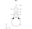
図4は、ユーザに提供される仮想空間2の概要を説明する図である。この図に示すように、仮想空間2は、中心21の360°方向全体を覆う全天球状の構造を有する。図4には、仮想空間2の全体のうち上半分の天球のみを例示する。仮想空間2には、略正方形または略長方形の複数のメッシュが関連付けられている。仮想空間2における各メッシュの位置は、仮想空間2に規定される空間座標系(XYZ座標系)における座標として、予め規定されている。制御回路部200は、仮想空間2に展開可能なコンテンツ(静止画、動画等)を構成する各部分画像を、仮想空間2における対応する各メッシュに対応付けることによって、ユーザによって視認可能な仮想空間画像22が展開される仮想空間2をユーザに提供する。
(Outline of virtual space 2)
FIG. 4 is a diagram illustrating an outline of thevirtual space 2 provided to the user. As shown in this figure, thevirtual space 2 has a spherical structure that covers the entire 360 ° direction of thecenter 21. FIG. 4 illustrates only the upper half celestial sphere in the entirevirtual space 2. A plurality of substantially square or substantially rectangular meshes are associated with thevirtual space 2. The position of each mesh in thevirtual space 2 is defined in advance as coordinates in a space coordinate system (XYZ coordinate system) defined in thevirtual space 2. Thecontrol circuit unit 200 associates each partial image constituting content (still image, moving image, etc.) that can be developed in thevirtual space 2 with each corresponding mesh in thevirtual space 2, thereby enabling the virtual space image that can be visually recognized by the user. Thevirtual space 2 in which 22 is expanded is provided to the user.

仮想空間2には、中心21を原点とするXYZ空間座標系が規定されている。XYZ座標系は、たとえばグローバル座標系に平行である。XYZ座標系は視点座標系の一種であるため、XYZ座標系における横方向、鉛直方向(上下方向)、および前後方向を、それぞれX軸、Y軸、Z軸とする。すなわち、XYZ座標系のX軸(横方向)がグローバル座標系のx軸と平行であり、XYZ座標系のY軸(上下方向)がグローバル座標系のy軸と平行であり、XYZ座標系のZ軸(前後方向)がグローバル座標系のz軸と平行である。  Thevirtual space 2 defines an XYZ space coordinate system with thecenter 21 as the origin. The XYZ coordinate system is parallel to the global coordinate system, for example. Since the XYZ coordinate system is a kind of viewpoint coordinate system, the horizontal direction, vertical direction (vertical direction), and front-rear direction in the XYZ coordinate system are defined as an X axis, a Y axis, and a Z axis, respectively. That is, the X axis (horizontal direction) of the XYZ coordinate system is parallel to the x axis of the global coordinate system, the Y axis (vertical direction) of the XYZ coordinate system is parallel to the y axis of the global coordinate system, and The Z axis (front-rear direction) is parallel to the z axis of the global coordinate system.

HMD110の起動時(初期状態)において、仮想空間2の中心21に仮想カメラ1が配置されている。仮想カメラ1は、現実空間内におけるHMD110の動きに連動して、仮想空間2内において同様に動く。これにより、現実空間内におけるHMD110の位置および向きの変化が、仮想空間2内において同様に再現される。  When theHMD 110 is activated (initial state), thevirtual camera 1 is arranged at thecenter 21 of thevirtual space 2. Thevirtual camera 1 moves similarly in thevirtual space 2 in conjunction with the movement of theHMD 110 in the real space. Thereby, changes in the position and orientation of theHMD 110 in the real space are similarly reproduced in thevirtual space 2.

仮想カメラ1には、HMD110と同様にuvw視野座標系が規定される。仮想空間2内における仮想カメラ1のuvw視野座標系は、現実空間(グローバル座標系)内におけるHMD110のuvw視野座標系に連動するように規定されている。したがって、HMD110の傾きが変化すると、それに連動して仮想カメラ1の傾きも変化する。仮想カメラ1は、HMD110を装着したユーザの現実空間における移動に連動して、仮想空間2において移動することもできる。  As with theHMD 110, the uvw visual field coordinate system is defined for thevirtual camera 1. The uvw visual field coordinate system of thevirtual camera 1 in thevirtual space 2 is defined so as to be linked to the uvw visual field coordinate system of theHMD 110 in the real space (global coordinate system). Therefore, when the inclination of theHMD 110 changes, the inclination of thevirtual camera 1 also changes accordingly. Thevirtual camera 1 can also move in thevirtual space 2 in conjunction with the movement of the user wearing theHMD 110 in the real space.

仮想空間2における仮想カメラ1の位置および傾きに応じて、仮想空間2における仮想カメラ1の向きが決まる。これにより、仮想空間2に展開される仮想空間画像22をユーザが視認する際の基準となる視線(基準視線5)が決まる。制御回路部200は、基準視線5に基づき、仮想空間2における視界領域23を決定する。視界領域23は、仮想空間2のうち、HMD110を装着したユーザの視界に対応する領域である。  The orientation of thevirtual camera 1 in thevirtual space 2 is determined according to the position and inclination of thevirtual camera 1 in thevirtual space 2. As a result, a line of sight (reference line of sight 5) as a reference when the user visually recognizes thevirtual space image 22 developed in thevirtual space 2 is determined. Thecontrol circuit unit 200 determines thevisual field region 23 in thevirtual space 2 based on the referencevisual line 5. Thevisual field area 23 is an area corresponding to the visual field of the user wearing theHMD 110 in thevirtual space 2.

図5は、視界領域23の断面を示す図である。図5の(a)に、仮想空間2において視界領域23をX方向から見たYZ断面を示す。図5の(b)に、仮想空間2において視界領域23をY方向から見たXZ断面を示す。視界領域23は、基準視線5と仮想空間2のYZ断面とによって定義される範囲である第1領域24(図5の(a)参照)と、基準視線5と仮想空間2のXZ断面とによって定義される範囲である第2領域25(図5の(b)参照)とを有する。制御回路部200は、仮想空間2における基準視線5を中心として極角αを含む範囲を、第1領域24として設定する。また、仮想空間2における基準視線5を中心とした方位角βを含む範囲を、第2領域25として設定する。  FIG. 5 is a view showing a cross section of thevisual field region 23. FIG. 5A shows a YZ cross section of thevisual field region 23 viewed from the X direction in thevirtual space 2. FIG. 5B shows an XZ cross-section of thevisual field region 23 viewed from the Y direction in thevirtual space 2. Thevisual field region 23 is defined by the first region 24 (see FIG. 5A) that is a range defined by the reference line ofsight 5 and the YZ section of thevirtual space 2, and the reference line ofsight 5 and the XZ section of thevirtual space 2. And a second region 25 (see FIG. 5B) which is a defined range. Thecontrol circuit unit 200 sets a range including the polar angle α around the reference line ofsight 5 in thevirtual space 2 as thefirst region 24. In addition, a range including the azimuth angle β around the reference line ofsight 5 in thevirtual space 2 is set as thesecond region 25.

HMDシステム100は、仮想空間画像22のうち視界領域23に重畳する部分である視界画像26をHMD110のディスプレイ112に表示させることによって、ユーザに仮想空間2を提供する。ユーザがHMD110を動かせば、それに連動して仮想カメラ1も動き、その結果、仮想空間2における視界領域23の位置が変化する。これによりディスプレイ112に表示される視界画像26が、仮想空間画像22のうち、仮想空間2においてユーザが向いた箇所(=視界領域23)に重畳する画像に更新される。したがってユーザは、仮想空間2における所望の箇所を視認することができる。  TheHMD system 100 provides the user with thevirtual space 2 by causing thedisplay image 112 of theHMD 110 to display aview image 26 that is a portion of thevirtual space image 22 that is superimposed on theview region 23. If the user moves theHMD 110, thevirtual camera 1 also moves in conjunction with it, and as a result, the position of thevisual field area 23 in thevirtual space 2 changes. As a result, theview image 26 displayed on thedisplay 112 is updated to an image that is superimposed on a portion of thevirtual space image 22 where the user faces (= view region 23). Therefore, the user can visually recognize a desired location in thevirtual space 2.

ユーザは、HMD110を装着している間、現実世界を目にすることなく、仮想空間2に展開される仮想空間画像22のみを視認する。そのためHMDシステム100は、仮想空間2への高い没入感をユーザに与えることができる。  While wearing theHMD 110, the user visually recognizes only thevirtual space image 22 developed in thevirtual space 2 without seeing the real world. Therefore, theHMD system 100 can give a high immersive feeling to thevirtual space 2 to the user.

制御回路部200は、HMD110を装着したユーザの現実空間における移動に連動して、仮想カメラ1を仮想空間2内において移動させてもよい。この場合、制御回路部200は、仮想カメラ1の仮想空間2内における位置および向きに基づき、仮想空間2のうちHMD110のディスプレイ112に投影されることによってユーザが視認する視界領域23を特定する。  Thecontrol circuit unit 200 may move thevirtual camera 1 in thevirtual space 2 in conjunction with the movement of the user wearing theHMD 110 in the real space. In this case, thecontrol circuit unit 200 identifies thevisual field region 23 that is visually recognized by the user by being projected on thedisplay 112 of theHMD 110 in thevirtual space 2 based on the position and orientation of thevirtual camera 1 in thevirtual space 2.

仮想カメラ1は、右眼用画像を提供する右眼用仮想カメラと、左眼用画像を提供する左眼用仮想カメラとを含むことが好ましい。さらに、2つの仮想カメラには、ユーザが3次元の仮想空間2を認識できるように適切な視差が設定されていることが好ましい。本実施形態では、このような2つの仮想カメラのロール方向が合成されることによって生成されるロール方向(w)がHMD110のロール方向(w)に適合されるような仮想カメラ1のみを、代表して図示および説明するものとする。  Thevirtual camera 1 preferably includes a right-eye virtual camera that provides a right-eye image and a left-eye virtual camera that provides a left-eye image. Furthermore, it is preferable that appropriate parallax is set for the two virtual cameras so that the user can recognize the three-dimensionalvirtual space 2. In the present embodiment, only thevirtual camera 1 in which the roll direction (w) generated by combining the roll directions of the two virtual cameras is adapted to the roll direction (w) of theHMD 110 is represented. Will be shown and described.

(視線方向の検出)
注視センサ130は、ユーザの右目および左目の視線が向けられる方向(視線方向)を検出するアイトラッキング機能を有する。注視センサ130として、アイトラッキング機能を有する公知のセンサを採用することができる。注視センサ130は、右目用センサおよび左目用センサを備えていることが好ましい。注視センサ130は、たとえば、ユーザの右目および左目に赤外光を照射すると共に、照射光に対する角膜および虹彩からの反射光を受光することによって、各眼球の回転角を検出するセンサでもよい。注視センサ130は、検出した各回転角に基づき、ユーザの視線方向を検知することができる。
(Gaze direction detection)
Thegaze sensor 130 has an eye tracking function that detects the direction (gaze direction) in which the line of sight of the user's right eye and left eye is directed. As thegaze sensor 130, a known sensor having an eye tracking function can be employed. Thegaze sensor 130 preferably includes a right eye sensor and a left eye sensor. Thegaze sensor 130 may be, for example, a sensor that detects the rotation angle of each eyeball by irradiating the user's right eye and left eye with infrared light and receiving reflected light from the cornea and iris with respect to the irradiated light. Thegaze sensor 130 can detect the direction of the user's line of sight based on each detected rotation angle.

注視センサ130によって検出されるユーザの視線方向は、ユーザが物体を視認する際の視点座標系における方向である。上述したように、HMD110のuvw視野座標系は、ユーザがディスプレイ112を視認する際の視点座標系に等しい。また、仮想カメラ1のuvw視野座標系は、HMD110のuvw視野座標系に連動している。したがってHMDシステム100では、注視センサ130によって検出されたユーザの視線方向を、仮想カメラ1のuvw視野座標系におけるユーザの視線方向と見なすことができる。  The user's gaze direction detected by thegaze sensor 130 is a direction in the viewpoint coordinate system when the user visually recognizes the object. As described above, the uvw visual field coordinate system of theHMD 110 is equal to the viewpoint coordinate system when the user visually recognizes thedisplay 112. Further, the uvw visual field coordinate system of thevirtual camera 1 is linked to the uvw visual field coordinate system of theHMD 110. Therefore, in theHMD system 100, the user's line-of-sight direction detected by thegaze sensor 130 can be regarded as the user's line-of-sight direction in the uvw visual field coordinate system of thevirtual camera 1.

図6は、ユーザの視線方向を決定する方法を例示する図である。この図に示すように、注視センサ130は、ユーザUの右目および左目の視線を検出する。ユーザUが近くを見ている場合、注視センサ130は、ユーザUの視線R1およびL1を検出する。ユーザが遠くを見ている場合、注視センサ130は、ユーザの視線R1およびL1よりも、HMD110のロール方向(w)とのなす角が小さい視線R2およびL2を特定する。注視センサ130は、検出値を制御回路部200に送信する。  FIG. 6 is a diagram illustrating a method of determining the user's line-of-sight direction. As shown in this figure, thegaze sensor 130 detects the line of sight of the right eye and the left eye of the user U. When the user U is looking nearby, thegaze sensor 130 detects the line of sight R1 and L1 of the user U. When the user looks far away, thegaze sensor 130 identifies the line of sight R2 and L2 that are smaller in angle with the roll direction (w) of theHMD 110 than the line of sight R1 and L1 of the user. Thegaze sensor 130 transmits the detection value to thecontrol circuit unit 200.

制御回路部200は、視線の検出値として視線R1およびL1を受信した場合、両者の交点である注視点N1を特定する。一方、視線R2およびL2を受信した場合も、両者の交点である注視点N2(不図示)を特定する。制御回路部200は、特定した注視点N1に基づき、ユーザUの視線方向N0を検出する。制御回路部200は、たとえば、ユーザUの右目Rと左目Lとを結ぶ直線の中点と、注視点N1とを通る直線の伸びる方向を、視線方向N0として検出する。視線方向N0は、ユーザUが両目により実際に視線を向けている方向である。視線方向N0はまた、視界領域23に対してユーザUが実際に視線を向けている方向でもある。  When receiving the line of sight R1 and L1 as the line-of-sight detection value, thecontrol circuit unit 200 specifies the gazing point N1 that is the intersection of the two. On the other hand, also when the lines of sight R2 and L2 are received, the gazing point N2 (not shown) that is the intersection of the two is specified. Thecontrol circuit unit 200 detects the gaze direction N0 of the user U based on the identified gazing point N1. For example, thecontrol circuit unit 200 detects, as the line-of-sight direction N0, the direction in which the straight line passing through the midpoint of the straight line connecting the right eye R and the left eye L of the user U and the gazing point N1 extends. The line-of-sight direction N0 is a direction in which the user U actually points the line of sight with both eyes. The line-of-sight direction N0 is also a direction in which the user U actually directs his / her line of sight with respect to thevisual field region 23.

HMDシステム100は、HMDシステム100を構成するいずれかの要素に、マイクおよびスピーカを備えていてもよい。これにより、ユーザは仮想空間2内に対して、音声による指示を与えることができる。また、仮想空間内の仮想テレビにテレビ番組の放送を受信するために、HMDシステム100はいずれかの要素にテレビジョン受像機を含んでいてもよい。また、ユーザが取得した電子メール等を表示させるための、通信機能等を含んでいてもよい。  TheHMD system 100 may include a microphone and a speaker in any element constituting theHMD system 100. Thereby, the user can give a voice instruction to thevirtual space 2. Further, in order to receive a broadcast of a television program on a virtual television in a virtual space, theHMD system 100 may include a television receiver as any element. Further, it may include a communication function or the like for displaying an electronic mail or the like acquired by the user.

(コントローラ300)
図7は、コントローラ300の構成を表す図である。コントローラ300は、ユーザの身体の一部の動きを検知することにより、仮想オブジェクトの動きを制御するために用いる装置の一例である。図1および図7に示すように、コントローラ300は、ユーザが右手に持って使用する右コントローラ320と、ユーザが左手に持って使用する左コントローラ330とからなる。右コントローラ320および左コントローラ330は、それぞれ別体の装置として構成される。ユーザは、右コントローラ320を持った右手と、左コントローラ330を持った左手とを、相互に自由に動かすことができる。なお、ユーザの頭部以外である身体の一部の動きを検知するための方法は、当該身体の一部に装着されるセンサを含むコントローラを用いる例に限られず、画像認識、その他任意の物理的、光学的な手法等を適用できる。例えば、外部カメラを用いてユーザの身体の一部の初期位置を特定し、継続的にユーザの身体の一部の位置を特定することにより、ユーザの頭部以外である身体の一部の動きを検知できる。以下の説明においては、コントローラ300を用いたユーザの頭部以外である身体の一部の動きの検知について詳述する。
(Controller 300)
FIG. 7 is a diagram illustrating the configuration of thecontroller 300. Thecontroller 300 is an example of an apparatus used to control the movement of a virtual object by detecting the movement of a part of the user's body. As shown in FIG. 1 and FIG. 7, thecontroller 300 includes aright controller 320 that the user uses with the right hand and aleft controller 330 that the user uses with the left hand. Theright controller 320 and theleft controller 330 are configured as separate devices. The user can freely move the right hand holding theright controller 320 and the left hand holding theleft controller 330 to each other. The method for detecting the movement of a part of the body other than the user's head is not limited to an example using a controller including a sensor attached to the part of the body. An optical method or the like can be applied. For example, by identifying the initial position of a part of the user's body using an external camera and continuously identifying the position of the part of the user's body, the movement of the part of the body other than the user's head Can be detected. In the following description, detection of movement of a part of the body other than the user's head using thecontroller 300 will be described in detail.

図1および図7に示すように、右コントローラ320および左コントローラ330は、それぞれ、操作ボタン302、赤外線LED(Light Emitting Diode)304、センサ306、およびトランシーバ308を備えている。後述するように、右コントローラ320および左コントローラ330は、赤外線LED304およびセンサ306のうちいずれか一方のみを備えていてもよい。  As shown in FIGS. 1 and 7, theright controller 320 and theleft controller 330 each include anoperation button 302, an infrared LED (Light Emitting Diode) 304, asensor 306, and atransceiver 308. As will be described later, theright controller 320 and theleft controller 330 may include only one of theinfrared LED 304 and thesensor 306.

操作ボタン302は、コントローラ300に対するユーザからの操作入力を受け取るように構成された複数のボタン群である。本実施形態では、操作ボタン302は、プッシュ式ボタン、トリガー式ボタン、およびアナログスティックを含む。  Theoperation buttons 302 are a group of buttons configured to receive operation inputs from the user for thecontroller 300. In the present embodiment, theoperation button 302 includes a push button, a trigger button, and an analog stick.

プッシュ式ボタンは、親指で下向きに押下する動作によって操作するように構成されたボタンである。右コントローラ320は、プッシュ式ボタンとして、天面322上に親指ボタン302aおよび302bを備えている。左コントローラ330は、プッシュ式ボタンとして、天面332上に2つの親指ボタン302cおよび302dを備えている。親指ボタン302aおよび302bは、いずれも右手の親指によって操作(押下)される。親指ボタン302cおよび302dは、いずれも左手の親指によって操作(押下)される。  The push-type button is a button configured to be operated by an operation of pressing downward with a thumb. Theright controller 320 includesthumb buttons 302a and 302b on thetop surface 322 as push buttons. Theleft controller 330 includes twothumb buttons 302c and 302d on thetop surface 332 as push buttons. Boththumb buttons 302a and 302b are operated (pressed) with the thumb of the right hand. Boththumb buttons 302c and 302d are operated (pressed) with the thumb of the left hand.

トリガー式ボタンは、人差し指または中指で引き金を引くような動作によって操作するように構成されたボタンである。右コントローラ320は、トリガー式ボタンとして、グリップ324の前面部分に人差し指ボタン302eを備えており、さらに、グリップ324の側面部分に中指ボタン302fを備えている。左コントローラ330は、トリガー式ボタンとして、グリップ334の前面部分に人差し指ボタン302gを備えており、さらに、グリップ334の側面部分に中指ボタン302hを備えている。人差し指ボタン302e、中指ボタン302f、人差し指ボタン302g、および中指ボタン302hは、それぞれ右手の人差し指、右手の中指、左手の人差し指、および左手の中指によって操作(押下)される。  The trigger type button is a button configured to be operated by an operation of pulling a trigger with an index finger or a middle finger. Theright controller 320 includes aforefinger button 302e on the front surface portion of thegrip 324 as a trigger button, and further includes amiddle finger button 302f on a side surface portion of thegrip 324. Theleft controller 330 includes aforefinger button 302g on the front portion of thegrip 334 as a trigger type button, and further includes amiddle finger button 302h on a side portion of thegrip 334. Theindex finger button 302e, themiddle finger button 302f, theindex finger button 302g, and themiddle finger button 302h are operated (pressed) by the index finger of the right hand, the middle finger of the right hand, the index finger of the left hand, and the middle finger of the left hand, respectively.

右コントローラ320は、親指ボタン302aおよび302b、人差し指ボタン302e、ならびに中指ボタン302fの押下状態をそれぞれ検出し、これらの検出値を制御回路部200に出力する。一方、左コントローラ330は、親指ボタン302cおよび302d、人差し指ボタン302g、ならびに中指ボタン302hの押下状態をそれぞれ検出し、これらの検出値を制御回路部200に出力する。  Theright controller 320 detects the pressed state of thethumb buttons 302 a and 302 b, theindex finger button 302 e, and themiddle finger button 302 f, and outputs these detected values to thecontrol circuit unit 200. On the other hand, theleft controller 330 detects the pressed state of thethumb buttons 302c and 302d, theindex finger button 302g, and themiddle finger button 302h, and outputs these detected values to thecontrol circuit unit 200.

本実施形態では、右コントローラ320および左コントローラ330の各ボタンの押下状態の検出値は、0から1のいずれかの値を取り得る。たとえば、ユーザが親指ボタン302aをまったく押下していない場合、親指ボタン302aの押下状態として「0」が検出される。一方、ユーザが親指ボタン302aを完全に(最も深く)押下している場合、親指ボタン302aの押下状態として「1」が検出される。  In the present embodiment, the detection value of the pressed state of each button of theright controller 320 and theleft controller 330 can take any value from 0 to 1. For example, when the user has not pressed thethumb button 302a at all, “0” is detected as the pressing state of thethumb button 302a. On the other hand, when the user presses thethumb button 302a completely (deepest), “1” is detected as the pressing state of thethumb button 302a.

アナログスティックは、所定のニュートラル位置から360°任意の方向へ傾けて操作することが可能なスティック型のボタンである。右コントローラ320の天面322上にアナログスティック302iが設けられ、左コントローラ330の天面332上にアナログスティック302jが設けられる。アナログスティック302iおよび302jは、それぞれ右手および左手の親指によって操作される。  The analog stick is a stick-type button that can be operated by being tilted 360 degrees from a predetermined neutral position. An analog stick 302 i is provided on thetop surface 322 of theright controller 320, and ananalog stick 302 j is provided on thetop surface 332 of theleft controller 330. Analog sticks 302i and 302j are operated by the thumbs of the right hand and the left hand, respectively.

右コントローラ320および左コントローラ330は、それぞれ、グリップ(324および334)の両側面から天面(322および332)とは反対側の方向へ延びて半円状のリングを形成するフレーム326および336を備えている。各フレーム326および336の外表面には、複数の赤外線LED304が埋め込まれている。複数(たとえば10個程度)の赤外線LED304が、フレーム326、336の円周方向に沿って一列に並んで設けられる。フレーム326および336の円周方向に沿って、複数列(たとえば2列)の赤外線LED304が配置されていてもよい。  Theright controller 320 and theleft controller 330 respectively haveframes 326 and 336 that form semicircular rings extending from opposite sides of the grips (324 and 334) in a direction opposite to the top surface (322 and 332). I have. A plurality ofinfrared LEDs 304 are embedded on the outer surfaces of theframes 326 and 336. A plurality of (for example, about 10)infrared LEDs 304 are provided in a line along the circumferential direction of theframes 326 and 336. A plurality of rows (for example, two rows) ofinfrared LEDs 304 may be arranged along the circumferential direction of theframes 326 and 336.

ユーザがコントローラ300を握る際、ユーザの各指はグリップ(324または334)とフレーム(326または336)との間にある。したがって、各フレーム326および336の外表面に配置された赤外線LED304は、ユーザの手または指によって覆い隠されてしまうことはない。フレーム326および336の外表面に加えて、さらに、グリップ324および334の表面のうちユーザの指で隠されない部分にも、赤外線LED304が設けられていてもよい。赤外線LED304は、コンピュータゲームのプレイ中に赤外線を発光する。赤外線LED304から発せられた赤外光は、右コントローラ320および左コントローラ330のそれぞれの位置および傾きを検出するために利用される。  When the user grips thecontroller 300, each finger of the user is between the grip (324 or 334) and the frame (326 or 336). Therefore, theinfrared LED 304 arranged on the outer surface of each of theframes 326 and 336 is not covered by the user's hand or finger. In addition to the outer surfaces of theframes 326 and 336,infrared LEDs 304 may also be provided on portions of the surfaces of thegrips 324 and 334 that are not hidden by the user's finger. Theinfrared LED 304 emits infrared light during the play of a computer game. Infrared light emitted from theinfrared LED 304 is used to detect the respective positions and inclinations of theright controller 320 and theleft controller 330.

右コントローラ320および左コントローラ330は、赤外線LED304の代わりに、または赤外線LED304に加えて、さらにセンサ306を内蔵する。センサ306は、たとえば磁気センサ、角速度センサ、若しくは加速度センサのいずれか、またはこれらの組み合わせであってよい。センサ306によっても、右コントローラ320および左コントローラ330の位置および傾きを検出することができる。  Theright controller 320 and theleft controller 330 further incorporate asensor 306 instead of or in addition to theinfrared LED 304. Thesensor 306 may be, for example, a magnetic sensor, an angular velocity sensor, an acceleration sensor, or a combination thereof. The position and inclination of theright controller 320 and theleft controller 330 can also be detected by thesensor 306.

センサ306は、ユーザが右コントローラ320および左コントローラ330をそれぞれ右手および左手で持って動かした際、右コントローラ320および左コントローラ330の向きおよび動きに応じた値(磁気、角速度、または加速度の値)を、出力する。制御回路部200は、センサ306からの出力値を適宜の方法によって加工することによって、右コントローラ320および左コントローラ330のそれぞれの位置および傾きを検出することができる。  When the user moves theright controller 320 and theleft controller 330 with the right hand and the left hand, respectively, thesensor 306 is a value corresponding to the direction and movement of theright controller 320 and the left controller 330 (magnetic, angular velocity, or acceleration value). Is output. Thecontrol circuit unit 200 can detect the positions and inclinations of theright controller 320 and theleft controller 330 by processing the output value from thesensor 306 by an appropriate method.

トランシーバ308は、右コントローラ320および左コントローラ330と、制御回路部200との間でデータを送受信するように構成される。トランシーバ308は、ユーザが操作ボタン302を介して右コントローラ320または左コントローラ330に与えた操作入力に基づくデータを、制御回路部200へ送信する。また、トランシーバ308は、赤外線LED304の発光を右コントローラ320または左コントローラ330に指示する命令を、制御回路部200から受信する。さらに、トランシーバ308は、センサ306によって検出した各種の値に対応するデータを、制御回路部200へ送信する。  Thetransceiver 308 is configured to transmit and receive data between theright controller 320 and theleft controller 330 and thecontrol circuit unit 200. Thetransceiver 308 transmits data based on the operation input given by the user to theright controller 320 or theleft controller 330 via theoperation button 302 to thecontrol circuit unit 200. Further, thetransceiver 308 receives a command for instructing theright controller 320 or theleft controller 330 to emit theinfrared LED 304 from thecontrol circuit unit 200. Further, thetransceiver 308 transmits data corresponding to various values detected by thesensor 306 to thecontrol circuit unit 200.

右コントローラ320および左コントローラ330は、ユーザの手に振動による触覚フィードバックを伝えるためのバイブレータを備えていてもよい。この構成では、トランシーバ308は、上述した各データの送受信に加えて、バイブレータに触覚フィードバックを行わせるための命令を制御回路部200から受信することができる。トランシーバ308は、無線通信によってデータを送受信するように構成されるのが好適である。この構成では、右コントローラ320および左コントローラ330に有線通信用のケーブルが接続されないので、ユーザは、右コントローラ320を持った右手および左コントローラ330を持った左手を、より自由にそれぞれ動かせる。  Theright controller 320 and theleft controller 330 may include a vibrator for transmitting tactile feedback by vibration to the user's hand. In this configuration, thetransceiver 308 can receive a command for causing the vibrator to perform tactile feedback from thecontrol circuit unit 200 in addition to the transmission / reception of each data described above. Thetransceiver 308 is preferably configured to send and receive data via wireless communication. In this configuration, since the cable for wired communication is not connected to theright controller 320 and theleft controller 330, the user can move the right hand holding theright controller 320 and the left hand holding theleft controller 330 more freely.

コントローラセンサ140は、右コントローラ320および左コントローラ330の動きを検出するためのポジション・トラッキング機能を有する。コントローラセンサ140は、この機能によって、現実空間内における右コントローラ320および左コントローラ330の位置および傾きを検出する。この検出を実現するために、コントローラセンサ140は、右コントローラ320および左コントローラ330の赤外線LED304から発せられた赤外光を、それぞれ検出する。コントローラセンサ140は、たとえば、赤外波長領域において画像を撮像する赤外カメラを備えており、この赤外カメラによって撮像した画像のデータに基づき、右コントローラ320および左コントローラ330の位置および傾きを検出する。  Thecontroller sensor 140 has a position tracking function for detecting the movement of theright controller 320 and theleft controller 330. With this function, thecontroller sensor 140 detects the position and inclination of theright controller 320 and theleft controller 330 in the real space. In order to realize this detection, thecontroller sensor 140 detects infrared light emitted from theinfrared LEDs 304 of theright controller 320 and theleft controller 330, respectively. Thecontroller sensor 140 includes, for example, an infrared camera that captures an image in the infrared wavelength region, and detects the positions and inclinations of theright controller 320 and theleft controller 330 based on image data captured by the infrared camera. To do.

赤外カメラによって撮像された画像は、右コントローラ320および左コントローラ330の表面に埋め込まれている多数の赤外線LED304の配置を反映した明暗画像である。ある1つの撮像画像には、互いに左右に離れた2つの明点の集団が含まれ得る。2つの集団のうち左側の集団は、ユーザが右手で持っている右コントローラ320の赤外線LED304に対応する。右側の集団は、ユーザが左手で持っている左コントローラ330の赤外線LED304に対応する。コントローラセンサ140は、左側の集団を構成している明点の並んでいる方向から、右コントローラ320の傾きを検出する。たとえば、明点が撮像画像内で横方向(即ち水平方向)に並んでいる場合、右コントローラ320の傾きを、フレーム326が水平に保持された傾きとして検出すればよい。また、撮像画像内で明点の並んでいる方向が横方向からある角度だけ斜めになっている場合、右コントローラ320の傾きを、フレーム326が水平から当該角度だけ傾いた傾きとして検出すればよい。同様に、コントローラセンサ140は、撮像画像内における右側の集団を構成している明点の並んでいる方向から、左コントローラ330の傾きを検出する。  The image picked up by the infrared camera is a bright and dark image reflecting the arrangement of a large number ofinfrared LEDs 304 embedded in the surfaces of theright controller 320 and theleft controller 330. A certain captured image may include a group of two bright spots that are separated from each other on the left and right. The left group of the two groups corresponds to theinfrared LED 304 of theright controller 320 that the user has with the right hand. The group on the right side corresponds to theinfrared LED 304 of theleft controller 330 that the user has with his left hand. Thecontroller sensor 140 detects the inclination of theright controller 320 from the direction in which the bright spots constituting the left group are arranged. For example, when the bright spots are arranged in the horizontal direction (that is, in the horizontal direction) in the captured image, the inclination of theright controller 320 may be detected as the inclination in which theframe 326 is held horizontally. Further, when the direction in which the bright spots are arranged in the captured image is inclined by a certain angle from the horizontal direction, the inclination of theright controller 320 may be detected as the inclination in which theframe 326 is inclined by the angle from the horizontal. . Similarly, thecontroller sensor 140 detects the inclination of theleft controller 330 from the direction in which the bright spots constituting the right group in the captured image are arranged.

コントローラセンサ140は、撮像画像内の明点(赤外線LED304)を識別することによって、右コントローラ320および左コントローラ330の位置をそれぞれ検出する。たとえば、撮像画像から検出したされた2つの明点の集団のうち、左側の集団を構成している複数の明点の重心位置を、右コントローラ320の位置として検出する。さらに、右側の集団を構成している複数の明点の重心位置を、左コントローラ330の位置として検出する。  Thecontroller sensor 140 detects the positions of theright controller 320 and theleft controller 330 by identifying a bright point (infrared LED 304) in the captured image. For example, among the two bright spot groups detected from the captured image, the barycentric positions of a plurality of bright spots constituting the left group are detected as the position of theright controller 320. Further, the barycentric positions of a plurality of bright spots constituting the right group are detected as positions of theleft controller 330.

コントローラセンサ140の代わりに、右コントローラ320および左コントローラ330が、センサ306を用いて自身の位置および傾きを検出してもよい。この場合、たとえば、右コントローラ320の三軸角速度センサ(センサ306)が、右コントローラ320の3つの直交する各軸周りの回転を検出する。右コントローラ320は、各検出値に基づき、右コントローラ320がどちらの方向にどれだけ回転したかを検出し、さらに、逐次検出した回転方向と回転量とを累積することによって、右コントローラ320の傾きを算出する。同様に、左コントローラ330は、左コントローラ330の三軸角速度センサ(センサ306)からの検出値を用いて、左コントローラ330の傾きを算出すればよい。右コントローラ320および左コントローラ330は、三軸角速度センサの検出値に加えて、たとえば三軸磁気センサおよび/または三軸加速度センサからの検出値を併用してもよい。  Instead of thecontroller sensor 140, theright controller 320 and theleft controller 330 may detect their position and inclination using thesensor 306. In this case, for example, the three-axis angular velocity sensor (sensor 306) of theright controller 320 detects rotations about the three orthogonal axes of theright controller 320. Theright controller 320 detects how much theright controller 320 has rotated in which direction based on each detection value, and further accumulates the rotation direction and the rotation amount that are sequentially detected to thereby determine the inclination of theright controller 320. Is calculated. Similarly, theleft controller 330 may calculate the inclination of theleft controller 330 using the detection value from the triaxial angular velocity sensor (sensor 306) of theleft controller 330. Theright controller 320 and theleft controller 330 may use a detection value from, for example, a triaxial magnetic sensor and / or a triaxial acceleration sensor in addition to the detection value of the triaxial angular velocity sensor.

詳細な説明は省略するが、右コントローラ320は、三軸角速度センサ(センサ306)からの検出値を用いて、右コントローラ320の位置を検出することができる。また、左コントローラ330は、三軸角速度センサ(センサ306)からの検出値を用いて、左コントローラ330の位置を検出することができる。  Although a detailed description is omitted, theright controller 320 can detect the position of theright controller 320 using a detection value from the triaxial angular velocity sensor (sensor 306). Further, theleft controller 330 can detect the position of theleft controller 330 using the detection value from the triaxial angular velocity sensor (sensor 306).

(制御回路部200の機能的構成)
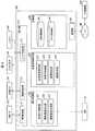
図8は、制御回路部200の機能的構成を示すブロック図である。制御回路部200は、HMDセンサ120、コントローラセンサ140、注視センサ130、およびコントローラ300から受信した各種のデータを用いることによって、ユーザに提供される仮想空間2を制御すると共に、HMD110のディスプレイ112への画像表示を制御する。図8に示すように、制御回路部200は、検出部210、表示制御部220、仮想空間制御部230、記憶部240、および通信部250を備えている。制御回路部200は、図2に示す各ハードウェアの協働によって、検出部210、表示制御部220、仮想空間制御部230、記憶部240、および通信部250として機能する。検出部210、表示制御部220、および仮想空間制御部230は、主としてプロセッサおよびメモリの協働によってその機能が実現され得る。記憶部240は、主としてメモリおよびストレージの協働によってその機能が実現され得る。通信部250は、主としてプロセッサおよび通信インターフェースの協働によってその機能が実現され得る。
(Functional configuration of control circuit unit 200)
FIG. 8 is a block diagram showing a functional configuration of thecontrol circuit unit 200. Thecontrol circuit unit 200 uses the various data received from theHMD sensor 120, thecontroller sensor 140, thegaze sensor 130, and thecontroller 300 to control thevirtual space 2 provided to the user and to thedisplay 112 of theHMD 110. Control image display. As illustrated in FIG. 8, thecontrol circuit unit 200 includes a detection unit 210, adisplay control unit 220, a virtualspace control unit 230, astorage unit 240, and acommunication unit 250. Thecontrol circuit unit 200 functions as a detection unit 210, adisplay control unit 220, a virtualspace control unit 230, astorage unit 240, and acommunication unit 250 by the cooperation of the hardware illustrated in FIG. The functions of the detection unit 210, thedisplay control unit 220, and the virtualspace control unit 230 can be realized mainly by the cooperation of the processor and the memory. The function of thestorage unit 240 can be realized mainly by the cooperation of the memory and the storage. The function of thecommunication unit 250 can be realized mainly by the cooperation of the processor and the communication interface.

検出部210は、制御回路部200に接続される各種のセンサ(HMDセンサ120等)から検出値を受信する。また、必要に応じて、受信した検出値を用いた所定の処理を実行する。検出部210は、HMD検出部211、視線検出部212、およびコントローラ検出部213を備えている。HMD検出部211は、HMD110およびHMDセンサ120から検出値をそれぞれ受信する。視線検出部212は、注視センサ130から検出値を受信する。コントローラ検出部213は、コントローラセンサ140、右コントローラ320、および左コントローラ330から、それぞれの検出値を受信する。  The detection unit 210 receives detection values from various sensors (such as the HMD sensor 120) connected to thecontrol circuit unit 200. Moreover, the predetermined process using the received detected value is performed as needed. The detection unit 210 includes anHMD detection unit 211, a line-of-sight detection unit 212, and acontroller detection unit 213. TheHMD detection unit 211 receives detection values from theHMD 110 and theHMD sensor 120, respectively. The line-of-sight detection unit 212 receives the detection value from thegaze sensor 130. Thecontroller detection unit 213 receives detection values from thecontroller sensor 140, theright controller 320, and theleft controller 330.

表示制御部220は、HMD110のディスプレイ112への画像表示を制御する。表示制御部220は、仮想カメラ制御部221、視界領域決定部222、および視界画像生成部223を備えている。仮想カメラ制御部221は、仮想空間2内に仮想カメラ1を配置すると共に、仮想空間2内における仮想カメラ1の挙動を制御する。視界領域決定部222は、視界領域23を決定する。視界画像生成部223は、決定された視界領域23に基づき、ディスプレイ112に表示される視界画像26を生成する。  Thedisplay control unit 220 controls image display on thedisplay 112 of theHMD 110. Thedisplay control unit 220 includes a virtualcamera control unit 221, a visual fieldregion determination unit 222, and a visual field image generation unit 223. The virtualcamera control unit 221 arranges thevirtual camera 1 in thevirtual space 2 and controls the behavior of thevirtual camera 1 in thevirtual space 2. The viewarea determination unit 222 determines theview area 23. The view image generation unit 223 generates aview image 26 displayed on thedisplay 112 based on thedetermined view area 23.

仮想空間制御部230は、ユーザに提供される仮想空間2を制御する。仮想空間制御部230は、仮想空間規定部231、仮想手制御部232、領域特定部233、および接触判定部234を備えている。  The virtualspace control unit 230 controls thevirtual space 2 provided to the user. The virtualspace control unit 230 includes a virtualspace defining unit 231, a virtualhand control unit 232, aregion specifying unit 233, and acontact determination unit 234.

仮想空間規定部231は、ユーザに提供される仮想空間2を表す仮想空間データを生成することによって、HMDシステム100における仮想空間2を規定する。仮想手制御部232は、ユーザによる右コントローラ320および左コントローラ330の操作に応じたユーザの各仮想手(仮想右手および仮想左手)を仮想空間2内に配置すると共に、仮想空間2内における各仮想手の挙動を制御する。領域特定部233は、仮想空間26におけるオブジェクト、すなわち仮想オブジェクトに、ユーザ操作の対象となる操作対象オブジェクト(たとえば仮想手)との接触を判定するための判定領域を設定する。接触判定部234は、前記判定領域と前記操作対象オブジェクトとの位置関係に基づいて、前記判定領域が設定される前記仮想オブジェクトと前記操作対象オブジェクトとの接触を判定する。  The virtualspace defining unit 231 defines thevirtual space 2 in theHMD system 100 by generating virtual space data representing thevirtual space 2 provided to the user. The virtualhand control unit 232 arranges each virtual hand (virtual right hand and virtual left hand) of the user in accordance with the operation of theright controller 320 and theleft controller 330 by the user in thevirtual space 2 and each virtual hand in thevirtual space 2 Control hand behavior. Theregion specifying unit 233 sets a determination region for determining contact with an operation target object (for example, a virtual hand) that is a user operation target on an object in thevirtual space 26, that is, a virtual object. Thecontact determination unit 234 determines contact between the virtual object in which the determination area is set and the operation target object based on a positional relationship between the determination area and the operation target object.

記憶部240は、制御回路部200が仮想空間2をユーザに提供するために用いる各種のデータを格納している。記憶部240は、雛形格納部241およびコンテンツ格納部242を備えている。雛形格納部241は、仮想空間2の雛形を表す各種の雛形データを格納している。コンテンツ格納部242は、仮想空間2において再生可能な各種のコンテンツを格納している。  Thestorage unit 240 stores various data used by thecontrol circuit unit 200 to provide thevirtual space 2 to the user. Thestorage unit 240 includes atemplate storage unit 241 and acontent storage unit 242. Thetemplate storage unit 241 stores various template data representing the template of thevirtual space 2. Thecontent storage unit 242 stores various types of content that can be reproduced in thevirtual space 2.

雛形データは、仮想空間2の空間構造を規定する空間構造データを有する。空間構造データは、たとえば、中心21を中心とする360°の全天球の空間構造を規定するデータである。雛形データは、仮想空間2のXYZ座標系を規定するデータをさらに有する。雛形データは、天球を構成する各メッシュのXYZ座標系における位置を特定する座標データをさらに有する。また、雛形データは、仮想空間2内に仮想オブジェクトを配置可能であるか否かを示すフラグをさらに有していてもよい。  The template data has spatial structure data that defines the spatial structure of thevirtual space 2. The spatial structure data is data that defines the spatial structure of a 360-degree celestial sphere centered on thecenter 21, for example. The template data further includes data defining the XYZ coordinate system of thevirtual space 2. The template data further includes coordinate data for specifying the position of each mesh constituting the celestial sphere in the XYZ coordinate system. The template data may further include a flag indicating whether or not a virtual object can be arranged in thevirtual space 2.

コンテンツは、仮想空間2において再生可能なコンテンツである。本実施形態では、このコンテンツはゲームコンテンツである。コンテンツは、ゲームの背景画像、および、ゲームに登場する仮想オブジェクト(キャラクタ、アイテム等)を規定するデータを少なくとも有する。各コンテンツには、HMD110の初期状態(起動時)にユーザに見せる画像を向いた初期方向が、予め規定されている。  The content is content that can be reproduced in thevirtual space 2. In the present embodiment, this content is game content. The content includes at least data defining a background image of the game and virtual objects (characters, items, etc.) appearing in the game. In each content, an initial direction facing an image to be shown to the user in the initial state (at the time of activation) of theHMD 110 is defined in advance.

通信部250は、ネットワークNWを介して外部機器400(たとえばゲームサーバ)との間でデータを送受信する。  The
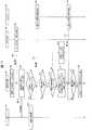
communication unit 250 transmits / receives data to / from an external device 400 (for example, a game server) via the network NW.

(仮想空間2の提供処理)
図9は、HMDシステム100が仮想空間2をユーザに提供する処理の流れを示すシーケンス図である。仮想空間2は、基本的に、HMD110および制御回路部200の協働によってユーザに提供される。図8に示す処理が開始されると、まず、ステップS1において、仮想空間規定部231が、ユーザに提供される仮想空間2を表す仮想空間データを生成することによって、仮想空間2を規定する。生成の手順は次の通りである。まず仮想空間規定部231は、仮想空間2の雛形データを雛形格納部241から取得することによって、仮想空間2の原型を定義する。仮想空間規定部231は、さらに、仮想空間2において再生されるコンテンツを、コンテンツ格納部242から取得する。本実施形態では、このコンテンツはゲームコンテンツである。
(Process of providing virtual space 2)
FIG. 9 is a sequence diagram showing a flow of processing in which theHMD system 100 provides thevirtual space 2 to the user. Thevirtual space 2 is basically provided to the user through the cooperation of theHMD 110 and thecontrol circuit unit 200. When the process shown in FIG. 8 is started, first, in step S1, the virtualspace defining unit 231 generates virtual space data representing thevirtual space 2 provided to the user, thereby defining thevirtual space 2. The generation procedure is as follows. First, the virtualspace defining unit 231 defines the prototype of thevirtual space 2 by acquiring the template data of thevirtual space 2 from thetemplate storage unit 241. The virtualspace defining unit 231 further acquires content to be played back in thevirtual space 2 from thecontent storage unit 242. In the present embodiment, this content is game content.

仮想空間規定部231は、取得した雛形データに、取得したコンテンツを適合することによって、仮想空間2を規定する仮想空間データを生成する。仮想空間規定部231は、仮想空間データにおいて、仮想空間2の天球を構成する各メッシュの管理データに、コンテンツに含まれる背景画像を構成する各部分画像を適宜関連付ける。仮想空間規定部231は、コンテンツに規定される初期方向を仮想空間2のXYZ座標系におけるZ方向に合致させるように、各部分画像と各メッシュとを関連付けることが好ましい。  The virtualspace defining unit 231 generates virtual space data defining thevirtual space 2 by adapting the acquired content to the acquired template data. The virtualspace defining unit 231 appropriately associates each partial image constituting the background image included in the content with management data of each mesh constituting the celestial sphere of thevirtual space 2 in the virtual space data. The virtualspace defining unit 231 preferably associates each partial image with each mesh so that the initial direction defined in the content matches the Z direction in the XYZ coordinate system of thevirtual space 2.

仮想空間規定部231は、さらに、必要に応じて、コンテンツに含まれる各仮想オブジェクトの管理データを、仮想空間データに追加する。その際、各管理データに、対応する仮想オブジェクトが仮想空間2において配置される位置を表す座標を設定する。これにより各仮想オブジェクトが、仮想空間2における当該座標の位置にそれぞれ配置される。  The virtualspace defining unit 231 further adds management data of each virtual object included in the content to the virtual space data as necessary. At that time, coordinates representing the position where the corresponding virtual object is arranged in thevirtual space 2 are set in each management data. Thus, each virtual object is arranged at the position of the coordinate in thevirtual space 2.

その後、ユーザによってHMD110が起動されると、ステップS2において、HMDセンサ120が、HMD110の初期状態における位置および傾きを検出して、ステップS3において、検出値を制御回路部200に出力する。HMD検出部211は、この検出値を受信する。この後、ステップS4において、仮想カメラ制御部221は、仮想空間2において仮想カメラ1を初期化する。  After that, when theHMD 110 is activated by the user, theHMD sensor 120 detects the position and inclination of theHMD 110 in the initial state in step S2, and outputs the detected value to thecontrol circuit unit 200 in step S3. TheHMD detection unit 211 receives this detection value. Thereafter, in step S <b> 4, the virtualcamera control unit 221 initializes thevirtual camera 1 in thevirtual space 2.

初期化の手順は次の通りである。まず仮想カメラ制御部221は、仮想空間2内における初期位置(図4における中心21等)に、仮想カメラ1を配置する。次に、仮想空間2における仮想カメラ1の向きを設定する。その際、仮想カメラ制御部221は、HMDセンサ120からの検出値に基づき初期状態のHMD110のuvw視野座標系を特定すると共に、HMD110のuvw視野座標系に一致するuvw視野座標系を仮想カメラ1に設定することによって、仮想カメラ1の向きを設定すればよい。仮想カメラ制御部221は、仮想カメラ1にuvw視野座標系を設定する際、仮想カメラ1のロール方向(w軸)をXYZ座標系のZ方向(Z軸)に適合させる。具体的には、仮想カメラ制御部221は、仮想カメラ1のロール方向をXZ平面に投影して得られる方向を、XYZ座標系のZ方向に一致させると共に、XZ平面に対する仮想カメラ1のロール方向の傾きを、水平面に対するHMD110のロール方向の傾きに一致させる。このような適合処理によって、初期状態の仮想カメラ1のロール方向がコンテンツの初期方向に適合されるので、コンテンツの再生開始後におけるユーザが最初に向く水平方向の向きを、コンテンツの初期方向に一致させることができる。  The initialization procedure is as follows. First, the virtualcamera control unit 221 places thevirtual camera 1 at an initial position in the virtual space 2 (eg, thecenter 21 in FIG. 4). Next, the orientation of thevirtual camera 1 in thevirtual space 2 is set. At that time, the virtualcamera control unit 221 specifies the uvw visual field coordinate system of theHMD 110 in the initial state based on the detection value from theHMD sensor 120 and sets the uvw visual field coordinate system that matches the uvw visual field coordinate system of theHMD 110 to thevirtual camera 1. The orientation of thevirtual camera 1 may be set by setting to. When setting the uvw visual field coordinate system for thevirtual camera 1, the virtualcamera control unit 221 adapts the roll direction (w axis) of thevirtual camera 1 to the Z direction (Z axis) of the XYZ coordinate system. Specifically, the virtualcamera control unit 221 matches the direction obtained by projecting the roll direction of thevirtual camera 1 on the XZ plane with the Z direction of the XYZ coordinate system, and the roll direction of thevirtual camera 1 with respect to the XZ plane. Is matched with the inclination of the roll direction of theHMD 110 with respect to the horizontal plane. By such adaptation processing, the roll direction of thevirtual camera 1 in the initial state is adapted to the initial direction of the content, so that the horizontal direction that the user first faces after the start of content reproduction matches the initial direction of the content. Can be made.

仮想カメラ1の初期化処理が終わると、視界領域決定部222は、仮想カメラ1のuvw視野座標系に基づき、仮想空間2における視界領域23を決定する。具体的には、仮想カメラ1のuvw視野座標系のロール方向(w軸)をユーザの基準視線5として特定し、この基準視線5に基づき視界領域23を決定する。ステップS5において、視界画像生成部223は、仮想空間データを処理することによって、仮想空間2に展開される仮想空間画像22の全体のうち、仮想空間2における視界領域23に投影される部分に相当する視界画像26を生成(レンダリング)する。ステップS6において、視界画像生成部223は、生成した視界画像26を初期視界画像としてHMD110に出力する。ステップS7において、HMD110は、受信した初期視界画像をディスプレイ112に表示する。これによりユーザは初期視界画像を視認する。  When the initialization process of thevirtual camera 1 is completed, the visual fieldregion determination unit 222 determines thevisual field region 23 in thevirtual space 2 based on the uvw visual field coordinate system of thevirtual camera 1. Specifically, the roll direction (w axis) of the uvw visual field coordinate system of thevirtual camera 1 is specified as the referencevisual line 5 of the user, and thevisual field region 23 is determined based on the referencevisual line 5. In step S <b> 5, the visual field image generation unit 223 processes the virtual space data, and corresponds to a portion projected to thevisual field region 23 in thevirtual space 2 out of the entirevirtual space image 22 developed in thevirtual space 2. Avisual field image 26 to be generated is generated (rendered). In step S6, the visual field image generation unit 223 outputs the generatedvisual field image 26 to theHMD 110 as an initial visual field image. In step S <b> 7, theHMD 110 displays the received initial view image on thedisplay 112. Thereby, the user visually recognizes the initial view image.

その後、ステップS8において、HMDセンサ120が、HMD110の現在の位置および傾きを検出して、ステップS9において、これらの検出値を制御回路部200に出力する。HMD検出部211は、各検出値を受信する。仮想カメラ制御部221は、HMD110の位置および傾きの検出値に基づき、HMD110における現在のuvw視野座標系を特定する。さらに、ステップS10において、仮想カメラ制御部221は、XYZ座標系におけるuvw視野座標系のロール方向(w軸)を、HMD110の視界方向として特定する。  Thereafter, in step S8, theHMD sensor 120 detects the current position and inclination of theHMD 110, and outputs these detected values to thecontrol circuit unit 200 in step S9. TheHMD detection unit 211 receives each detection value. The virtualcamera control unit 221 specifies the current uvw visual field coordinate system in theHMD 110 based on the position and tilt detection values of theHMD 110. Furthermore, in step S <b> 10, the virtualcamera control unit 221 specifies the roll direction (w axis) of the uvw visual field coordinate system in the XYZ coordinate system as the visual field direction of theHMD 110.

本実施形態では、ステップS11において、仮想カメラ制御部221が、特定したHMD110の視界方向を、仮想空間2におけるユーザの基準視線5として特定する。ステップS12において、仮想カメラ制御部221は、特定した基準視線5に基づき、仮想カメラ1を制御する。仮想カメラ制御部221は、基準視線5の位置(起点)および方向が仮想カメラ1の初期状態と同一であれば、仮想カメラ1の位置および方向をそのまま維持する。一方、基準視線5の位置(起点)および/または方向が、仮想カメラ1の初期状態から変化していれば、仮想空間2内における仮想カメラ1の位置および/または傾きを、変化後の基準視線5に応じた位置および/または傾きに変更する。また、制御後の仮想カメラ1に対してuvw視野座標系を再設定する。  In the present embodiment, in step S <b> 11, the virtualcamera control unit 221 specifies the identified visual field direction of theHMD 110 as the user's referencevisual line 5 in thevirtual space 2. In step S <b> 12, the virtualcamera control unit 221 controls thevirtual camera 1 based on the identified reference line ofsight 5. If the position (starting point) and direction of the reference line ofsight 5 are the same as the initial state of thevirtual camera 1, the virtualcamera control unit 221 maintains the position and direction of thevirtual camera 1 as they are. On the other hand, if the position (starting point) and / or direction of the reference line ofsight 5 has changed from the initial state of thevirtual camera 1, the position and / or inclination of thevirtual camera 1 in thevirtual space 2 is changed to the reference line of sight after the change. Change the position and / or inclination according to 5. Further, the uvw visual field coordinate system is reset for thevirtual camera 1 after the control.

ステップS13において、視界領域決定部222は、特定した基準視線5に基づき、仮想空間2における視界領域23を決定する。その後、ステップS14において、視界画像生成部223は、仮想空間データを処理することによって、仮想空間2に展開される仮想空間画像22の全体のうち、仮想空間2における視界領域23に投影(重畳)される部分である視界画像26を生成(レンダリング)する。ステップS15において、視界画像生成部223は、生成した視界画像26を更新用の視界画像としてHMD110に出力する。ステップS16において、HMD110は、受信した視界画像26をディスプレイ112に表示することによって、視界画像26を更新する。これにより、ユーザがHMD110を動かせば、それに連動して視界画像26が更新される。  In step S <b> 13, the visual fieldarea determination unit 222 determines thevisual field area 23 in thevirtual space 2 based on the identified referencevisual line 5. Thereafter, in step S <b> 14, the visual field image generation unit 223 processes (superimposes) the virtual space data on thevisual field region 23 in thevirtual space 2 among the entirevirtual space image 22 developed in thevirtual space 2 by processing the virtual space data. Aview field image 26 that is a portion to be generated is generated (rendered). In step S15, the visual field image generation unit 223 outputs the generatedvisual field image 26 to theHMD 110 as a visual field image for update. In step S <b> 16, theHMD 110 updates theview image 26 by displaying the receivedview image 26 on thedisplay 112. Thereby, if a user moves HMD110, theview image 26 will be updated in response to it.

(仮想空間ゲームの提供)
本実施形態では、ユーザは、右コントローラ320および左コントローラ330を操作することによって、仮想空間2内においてゲームをプレイする。このゲームでは、ユーザは、仮想空間2において、ユーザの頭部以外の身体の一部の動きに連動して動作する操作対象オブジェクトにより、他の仮想オブジェクトに触れることができる。詳細は後述するが、制御回路部200は、第1仮想オブジェクトが第2仮想オブジェクトと重畳しかつ第2仮想オブジェクトの前面に位置する重畳部分を含む場合、前記第1仮想オブジェクトと操作対象オブジェクトとの接触を判定するための判定領域を前記重畳部分と重畳するように設定し、前記第2仮想オブジェクトと操作対象オブジェクトとの接触を判定するための判定領域を前記重畳部分に重畳しないように設定する。これにより、ユーザは、直感的な操作により、第1仮想オブジェクトと第2仮想オブジェクトのうち、ユーザの所望の仮想オブジェクトに対して、操作対象オブジェクトを接触させることができる。前記ゲームは、たとえばカードゲームであってもよい。この場合、前記操作対象オブジェクトは仮想手であってもよく、前記第1仮想オブジェクトおよび前記第2仮想オブジェクトはユーザが選択できるカードの仮想オブジェクト(現実のカードを模した外観および形状の仮想オブジェクト)であってもよい。カードの仮想オブジェクトが複数重畳して配置されているような場合であっても、前記判定により、ユーザは、直感的な操作により、仮想手によって所望のカードの仮想オブジェクトに触れることができる。
(Provide virtual space game)
In the present embodiment, the user plays a game in thevirtual space 2 by operating theright controller 320 and theleft controller 330. In this game, the user can touch other virtual objects in thevirtual space 2 with an operation target object that operates in conjunction with the movement of a part of the body other than the user's head. Although details will be described later, when the first virtual object includes an overlapping portion that overlaps with the second virtual object and is positioned in front of the second virtual object, thecontrol circuit unit 200 includes the first virtual object, the operation target object, A determination area for determining the contact of the second virtual object is set so as to be superimposed on the overlapping portion, and a determination area for determining a contact between the second virtual object and the operation target object is set not to be superimposed on the overlapping portion. To do. Accordingly, the user can bring the operation target object into contact with the virtual object desired by the user among the first virtual object and the second virtual object by an intuitive operation. The game may be a card game, for example. In this case, the operation target object may be a virtual hand, and the first virtual object and the second virtual object are virtual objects of a card that can be selected by a user (a virtual object having an appearance and shape imitating a real card). It may be. Even in the case where a plurality of virtual objects of a card are arranged in a superimposed manner, the determination allows the user to touch the virtual object of a desired card with a virtual hand by an intuitive operation.

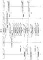
図10は、仮想空間2におけるゲーム中の処理の流れを示すシーケンス図である。ステップS20において、仮想空間規定部231は、選択画面を構成する各部分画像をコンテンツ格納部242から読み出し、仮想空間データにおいて、仮想空間2の天球を構成する各メッシュの管理データに、前記各部分画像を関連付ける。また、仮想空間規定部231は、選択画面に含まれる各仮想オブジェクトの管理データを、仮想空間データに追加する。仮想オブジェクトの管理データには、仮想オブジェクトの形状、仮想空間2における位置(座標)および傾き(姿勢)を示すデータが含まれている。仮想空間規定部231は、管理データを仮想空間データに追加する際、各管理データに、対応する仮想オブジェクトが仮想空間2において配置される位置を表す座標を設定する。前記仮想オブジェクトは、ユーザが選択する対象となる仮想オブジェクトであり、たとえばカードである。ユーザは、この仮想オブジェクトに対して、操作対象オブジェクトを接触させることにより、接触させた当該仮想オブジェクトを選択することができる。以下では、操作対象オブジェクトが仮想手である例を説明する。  FIG. 10 is a sequence diagram showing the flow of processing during the game in thevirtual space 2. In step S20, the virtualspace defining unit 231 reads each partial image constituting the selection screen from thecontent storage unit 242, and in the virtual space data, the management unit of each mesh constituting the celestial sphere of thevirtual space 2 is included in each of the parts. Associate images. In addition, the virtualspace defining unit 231 adds management data of each virtual object included in the selection screen to the virtual space data. The management data of the virtual object includes data indicating the shape of the virtual object, the position (coordinates) and the inclination (attitude) in thevirtual space 2. When adding the management data to the virtual space data, the virtualspace defining unit 231 sets coordinates representing the position where the corresponding virtual object is arranged in thevirtual space 2 for each management data. The virtual object is a virtual object to be selected by the user, for example, a card. The user can select the contacted virtual object by bringing the operation target object into contact with the virtual object. Hereinafter, an example in which the operation target object is a virtual hand will be described.

ステップS21において、コントローラセンサ140は、右コントローラ320の位置および傾き、ならびに、左コントローラ330の位置および傾きをそれぞれ検出する。ステップS22において、コントローラセンサ140は、各検出値を制御回路部200に送信する。コントローラ検出部213は、これらの検出値を受信する。  In step S21, thecontroller sensor 140 detects the position and inclination of theright controller 320 and the position and inclination of theleft controller 330, respectively. In step S <b> 22, thecontroller sensor 140 transmits each detection value to thecontrol circuit unit 200. Thecontroller detection unit 213 receives these detection values.

ステップS23において、コントローラ300は、各ボタンの押下状態を検出する。具体的には、右コントローラ320は、親指ボタン302a、人差し指ボタン302e、および中指ボタン302fの押下状態をそれぞれ検出する。一方、左コントローラ330は、親指ボタン302c、人差し指ボタン302g、および中指ボタン302hの押下状態をそれぞれ検出する。ステップS24において、右コントローラ320および左コントローラ330は、各検出値を制御回路部200に送信する。コントローラ検出部213は、これらの検出値を受信する。  In step S23, thecontroller 300 detects the pressed state of each button. Specifically, theright controller 320 detects the pressed state of thethumb button 302a, theindex finger button 302e, and themiddle finger button 302f, respectively. On the other hand, theleft controller 330 detects the pressed state of thethumb button 302c, theindex finger button 302g, and themiddle finger button 302h, respectively. In step S <b> 24, theright controller 320 and theleft controller 330 transmit each detection value to thecontrol circuit unit 200. Thecontroller detection unit 213 receives these detection values.

ステップS25において、仮想手制御部232は、受信した各検出値を用いて、ユーザの各仮想手(仮想右手および仮想左手)を、仮想空間2に生成する。具体的には、仮想右手を規定するデータおよび仮想左手を規定するデータをそれぞれ生成し、仮想空間データに追加する。  In step S <b> 25, the virtualhand control unit 232 generates each virtual hand (virtual right hand and virtual left hand) of the user in thevirtual space 2 using each received detection value. Specifically, data defining the virtual right hand and data defining the virtual left hand are respectively generated and added to the virtual space data.

仮想手制御部232は、右コントローラ320位置および傾きの検出値、ならびに右コントローラ320の各ボタンの押下状態の検出値を用いて、ユーザの仮想右手を規定する。その際、仮想空間2における仮想右手の位置として、グローバル座標系における右コントローラ320の位置を規定する。仮想手制御部232は、さらに、右コントローラ320の傾きの検出値に基づき、右コントローラ320に設定されたuvw視野座標系に連動するuvw視野座標系を仮想右手に設定することによって、仮想空間2内における仮想右手の傾きを規定する。  The virtualhand control unit 232 defines the user's virtual right hand using the detected value of the position and tilt of theright controller 320 and the detected value of the pressed state of each button of theright controller 320. At this time, the position of theright controller 320 in the global coordinate system is defined as the position of the virtual right hand in thevirtual space 2. The virtualhand control unit 232 further sets the uvw visual field coordinate system linked to the uvw visual field coordinate system set in theright controller 320 based on the detected value of the tilt of theright controller 320 to the virtualright hand 2. Defines the inclination of the virtual right hand inside.

仮想手制御部232は、さらに、右コントローラ320の親指ボタン302a、人差し指ボタン302e、および中指ボタン302fの各検出値に基づき、仮想右手を構成する右親指、右人差し指、および右中指の表示状態を規定する。なお、右薬指および右小指の表示状態は、右中指に合致させるように規定する。  The virtualhand control unit 232 further displays the display states of the right thumb, right index finger, and right middle finger constituting the virtual right hand based on the detected values of thethumb button 302a, theindex finger button 302e, and themiddle finger button 302f of theright controller 320. Stipulate. The display states of the right ring finger and the right little finger are defined to match the right middle finger.

仮想手制御部232は、あるボタンの押下状態の検出値が「0」の場合、そのボタンに対応する仮想手の指の表示状態として、指を完全に伸ばした状態を規定する。一方、あるボタンの押下状態が「1」の場合、そのボタンに対応する仮想手の指の表示状態として、指を完全に折り曲げた状態を規定する。また、あるボタンの押下状態が「中間(0と1との間の値)」の場合、そのボタンに対応する仮想手の指の表示状態として、押下状態に応じた程度に指を折り曲げた表示状態を規定する。  When the detected value of the pressed state of a button is “0”, the virtualhand control unit 232 defines a state where the finger is fully extended as the display state of the finger of the virtual hand corresponding to the button. On the other hand, when the pressed state of a certain button is “1”, the state in which the finger is completely bent is defined as the display state of the finger of the virtual hand corresponding to the button. When the pressed state of a button is “intermediate (value between 0 and 1)”, the display state of the finger of the virtual hand corresponding to the button is displayed by bending the finger to the extent corresponding to the pressed state. Specify the state.

同様に、仮想手制御部232は、左コントローラ330の各検出値に基づき、仮想空間2における仮想左手の位置、傾き、および各指の状態を規定する。これらの処理によって、仮想手制御部232は、仮想右手および仮想左手を、仮想空間2に配置する。  Similarly, the virtualhand control unit 232 defines the position and inclination of the virtual left hand in thevirtual space 2 and the state of each finger based on the detection values of theleft controller 330. Through these processes, the virtualhand control unit 232 places the virtual right hand and the virtual left hand in thevirtual space 2.

ステップS26〜ステップS34の処理は、図9のステップS8〜ステップS16と同様である。ステップS26〜ステップS34の処理により、ステップS20で仮想空間規定部231が生成した選択画面のうち、視界領域23に投影(重畳)される部分である視界画像がディスプレイ112に表示される。  The processing of step S26 to step S34 is the same as step S8 to step S16 of FIG. Through the processes in steps S26 to S34, a view field image that is a portion projected (superposed) on theview field area 23 in the selection screen generated by the virtualspace defining unit 231 in step S20 is displayed on thedisplay 112.

ステップS35では、ステップS23と同様に、コントローラ300は、各ボタンの押下状態を検出する。ステップS36では、コントローラ300は、各検出値を制御回路部200に送信する。コントローラ検出部213は、これらの検出値を受信する。  In step S35, as in step S23, thecontroller 300 detects the pressed state of each button. In step S <b> 36, thecontroller 300 transmits each detection value to thecontrol circuit unit 200. Thecontroller detection unit 213 receives these detection values.

ステップS37において、仮想空間規定部231は、前記受信した検出値に基づいて、仮想手に仮想オブジェクトをセットするための操作であるオブジェクトセット操作(第1操作)を検出したか否かを判定する。コントローラ300に対するどのような操作をオブジェクトセット操作とするかは予め決めておけばよい。たとえば、左コントローラ330の人差し指ボタン302gを押下する操作を、仮想左手に仮想オブジェクトをセットするためのオブジェクトセット操作としてもよい。  In step S37, the virtualspace defining unit 231 determines, based on the received detection value, whether or not an object setting operation (first operation) that is an operation for setting a virtual object in the virtual hand is detected. . What operation with respect to thecontroller 300 should be determined in advance is the object set operation. For example, an operation of pressing theindex finger button 302g of theleft controller 330 may be an object setting operation for setting a virtual object in the virtual left hand.

ステップS37において、仮想空間規定部231は、オブジェクトセット操作を検出したと判定した場合(ステップS37でYES)、仮想空間2における仮想手上(手のひら側が好ましい)に複数の仮想オブジェクトが重ねて配置された状態となるように、仮想空間データを更新する。たとえば、仮想オブジェクトOA〜ODを、上からOA、OB、OC、OCの順に仮想手上に配置する場合、仮想空間規定部231は、仮想オブジェクトODの位置を仮想手の直上の位置として仮想空間データを更新する。以下同様に、仮想オブジェクトOCの位置を仮想オブジェクトODの直上の位置とし、仮想オブジェクトOBの位置を仮想オブジェクトOCの直上の位置とし、仮想オブジェクトOAの位置を仮想オブジェクトOBの直上の位置として仮想空間データを更新する。  In step S37, when the virtualspace defining unit 231 determines that an object setting operation has been detected (YES in step S37), a plurality of virtual objects are arranged on top of the virtual hand (preferably on the palm side) in thevirtual space 2. The virtual space data is updated so as to be in the state. For example, when the virtual objects OA to OD are arranged on the virtual hand in the order of OA, OB, OC, and OC from the top, the virtualspace defining unit 231 uses the position of the virtual object OD as the position immediately above the virtual hand. Update the data. Similarly, the position of the virtual object OC is the position immediately above the virtual object OD, the position of the virtual object OB is the position immediately above the virtual object OC, and the position of the virtual object OA is the position immediately above the virtual object OB. Update the data.

そして、視界画像生成部223は、前記更新後の仮想空間データに基づいて視界画像26を生成し(ステップS38)、生成した視界画像26を更新用の視界画像としてHMD110に出力する(ステップS39)。ステップS40において、HMD110は、受信した視界画像26をディスプレイ112に表示することによって、視界画像26を更新する。これにより、ユーザは、仮想手上に複数の仮想オブジェクトが重畳して配置された画像を視認する。  Then, the visual field image generation unit 223 generates avisual field image 26 based on the updated virtual space data (Step S38), and outputs the generatedvisual field image 26 to theHMD 110 as an updated visual field image (Step S39). . In step S <b> 40, theHMD 110 updates theview image 26 by displaying the receivedview image 26 on thedisplay 112. Accordingly, the user visually recognizes an image in which a plurality of virtual objects are superimposed on the virtual hand.

ステップS41では、ステップS35と同様に、コントローラ300は、各ボタンの押下状態を検出する。ステップS42では、コントローラ300は、各検出値を制御回路部200に送信する。コントローラ検出部213は、これらの検出値を受信する。  In step S41, as in step S35, thecontroller 300 detects the pressed state of each button. In step S <b> 42, thecontroller 300 transmits each detection value to thecontrol circuit unit 200. Thecontroller detection unit 213 receives these detection values.

ステップS43において、仮想空間規定部231は、前記受信した検出値に基づいて、仮想手にセットされた仮想オブジェクトを広げる操作(第2操作)を検出したか否かを判定する。コントローラ300に対するどのような操作を、仮想オブジェクトを広げる操作とするかは予め決めておけばよい。たとえば、仮想左手上に仮想オブジェクトが配置された状態において、左コントローラ330の親指ボタン302cを完全に押下した後、アナログスティック302jを傾ける操作を、仮想オブジェクトを広げる操作としてもよい。また、たとえば、左コントローラ330の天面332をタッチパネルで構成した場合、該タッチパネルに対するスワイプ操作を、仮想オブジェクトを広げる操作としてもよい。この他にも、たとえば、仮想空間規定部231は、ユーザの親指の動きを光学的に検知した検知結果に基づき、ユーザの親指が仮想オブジェクトを広げるように動いたことを検出した場合に、仮想オブジェクトを広げる操作が行われたと判定してもよい。これにより、現実に手に持ったカードを広げるときと同じ感覚で親指を動かすという直感的な操作により、仮想空間2中のカードの仮想オブジェクトを広げることも可能になる。  In step S43, the virtualspace defining unit 231 determines whether an operation (second operation) for expanding the virtual object set in the virtual hand has been detected based on the received detection value. What kind of operation on thecontroller 300 should be determined in advance is an operation for expanding the virtual object. For example, in a state where the virtual object is placed on the virtual left hand, the operation of tilting theanalog stick 302j after completely pressing thethumb button 302c of theleft controller 330 may be an operation of expanding the virtual object. For example, when thetop surface 332 of theleft controller 330 is configured with a touch panel, a swipe operation on the touch panel may be an operation for expanding a virtual object. In addition to this, for example, when the virtualspace defining unit 231 detects that the user's thumb has moved to expand the virtual object based on a detection result obtained by optically detecting the movement of the user's thumb, It may be determined that an operation for expanding the object has been performed. Accordingly, it is possible to expand the virtual object of the card in thevirtual space 2 by an intuitive operation of moving the thumb with the same feeling as when the card actually held in the hand is expanded.

ステップS43において、仮想空間規定部231は、仮想オブジェクトを広げる操作を検出したと判定した場合(ステップS43でYES)、仮想手上に重畳して配置されている複数の仮想オブジェクトが広げられた状態となるように、仮想空間データを更新する。なお、複数の仮想オブジェクトが広げられた状態とは、他の仮想オブジェクトによって仮想カメラ1の死角となっている、仮想オブジェクトの部分(他の仮想オブジェクトとの重畳部分)の面積が狭くなった状態である。たとえば、仮想手上に重畳配置された仮想オブジェクトがカードの仮想オブジェクトであれば、各仮想オブジェクトを扇状にずらした状態であってもよい。  In step S43, when the virtualspace defining unit 231 determines that an operation for expanding a virtual object has been detected (YES in step S43), a state in which a plurality of virtual objects arranged in a superimposed manner on the virtual hand is expanded The virtual space data is updated so that The state in which a plurality of virtual objects are expanded is a state in which the area of the virtual object portion (the overlapping portion with other virtual objects) that is a blind spot of thevirtual camera 1 by another virtual object is reduced. It is. For example, if the virtual object superimposed on the virtual hand is a virtual object of a card, the virtual objects may be in a state of shifting in a fan shape.

ステップS44において、視界画像生成部223は、前記更新後の仮想空間データに基づいて視界画像26を生成し、ステップS45において、前記視界画像26を更新用の視界画像としてHMD110に出力する。ステップS46において、HMD110は、受信した視界画像26をディスプレイ112に表示することによって、視界画像26を更新する。これにより、ユーザは、仮想手上に複数の仮想オブジェクトが重なった状態で広げられた画像を視認する。  In step S44, the visual field image generation unit 223 generates avisual field image 26 based on the updated virtual space data. In step S45, thevisual field image 26 is output to theHMD 110 as a visual field image for update. In step S <b> 46, theHMD 110 updates theview image 26 by displaying the receivedview image 26 on thedisplay 112. As a result, the user visually recognizes an image that is spread in a state where a plurality of virtual objects overlap each other on the virtual hand.

ステップS47において、領域特定部233は、仮想オブジェクトと仮想手との接触を判定する際に使用する判定領域を設定する。判定領域を設定する処理の詳細は、図12に基づいて後述する。  In step S47, the
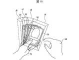
region specifying unit 233 sets a determination region used when determining contact between the virtual object and the virtual hand. Details of the process of setting the determination area will be described later with reference to FIG.

(表示する画像の例)
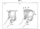
図10のステップS38において生成する視界画像26は、たとえば図11の(a)のような画像であってもよい。この例では、カードの仮想オブジェクトである仮想オブジェクトOAおよびOBが仮想左手OLに把持されている。仮想オブジェクトOAは、絵柄が正面(仮想カメラ1側)を向く配置となっているので、ユーザは仮想オブジェクトOAがどのようなカードであるかを認識することができる。一方、仮想オブジェクトOBは、仮想オブジェクトOAの背後に位置しており、その大部分が仮想オブジェクトOAによって死角となっているから、ユーザは仮想オブジェクトOBがどのようなカードであるかを認識することはできない。なお、仮想オブジェクトOBの背後にも複数の仮想オブジェクトが配置されているが、これらの仮想オブジェクトは仮想オブジェクトOAおよびOBに隠れており、表示されていない。
(Example of displayed image)
Thevisual field image 26 generated in step S38 in FIG. 10 may be an image as shown in FIG. In this example, virtual objects OA and OB, which are virtual objects of the card, are held by the virtual left hand OL. Since the virtual object OA is arranged so that the picture faces the front (thevirtual camera 1 side), the user can recognize what kind of card the virtual object OA is. On the other hand, since the virtual object OB is located behind the virtual object OA, and most of the virtual object OB is blind spotted by the virtual object OA, the user recognizes what kind of card the virtual object OB is. I can't. A plurality of virtual objects are also arranged behind the virtual object OB, but these virtual objects are hidden by the virtual objects OA and OB and are not displayed.

図10のステップS44において生成する視界画像26は、たとえば図11の(b)のような画像であってもよい。この例では、カードの仮想オブジェクトである仮想オブジェクトOA〜ODが仮想左手OLに把持されている。図11の(a)の状態と比べて、仮想手OL上における、仮想オブジェクトOA、OBの位置がそれぞれ変化しており、これにより仮想オブジェクトOA、OBの重畳部分の面積が狭くなっている。また、図11の(a)では仮想オブジェクトOA、OBの背後に隠れて視認できなかった仮想オブジェクトOC、ODについても視認できるようになっている。この結果、図11の(a)の画像では視認できなかった、仮想オブジェクトOB〜ODの左肩部分に表示されている数字を読み取ることができるようになっている。  The field-of-view image 26 generated in step S44 in FIG. 10 may be an image as shown in FIG. In this example, virtual objects OA to OD that are virtual objects of the card are held by the virtual left hand OL. Compared with the state of FIG. 11A, the positions of the virtual objects OA and OB on the virtual hand OL are changed, and the area of the overlapping portion of the virtual objects OA and OB is thereby reduced. Further, in FIG. 11A, the virtual objects OC and OD that are hidden behind the virtual objects OA and OB and cannot be visually recognized can be visually recognized. As a result, it is possible to read the numbers displayed on the left shoulder portions of the virtual objects OB to OD that could not be visually recognized in the image of FIG.

(判定領域を設定する処理)
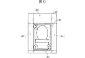
領域特定部233が判定領域を設定する処理(図10のステップS47)の詳細を図12に基づいて説明する。ステップS50において、領域特定部233は、各仮想オブジェクトの判定領域を設定する。前記判定領域は、仮想オブジェクトから仮想カメラ1に向かって延在する部分を少なくとも含むように、仮想オブジェクトの周囲の領域において設定する。領域特定部233は、設定した各判定領域を、対応する仮想オブジェクトと関連付けておく。なお、ステップS50で設定する判定領域については、図13に基づいて後述する。
(Process to set judgment area)
Details of the process of setting the determination area by the area specifying unit 233 (step S47 in FIG. 10) will be described with reference to FIG. In step S50, thearea specifying unit 233 sets a determination area for each virtual object. The determination area is set in an area around the virtual object so as to include at least a portion extending from the virtual object toward thevirtual camera 1. Thearea specifying unit 233 associates each set determination area with a corresponding virtual object. The determination area set in step S50 will be described later with reference to FIG.

ステップS51において、領域特定部233は、各仮想オブジェクトの重なりの状態、すなわち仮想カメラ1から見て、いずれの仮想オブジェクトがいずれの仮想オブジェクトに重なっているか、および重なっている仮想オブジェクトのいずれがより仮想カメラ1に近いかを特定する。具体的には、領域特定部233は、ステップS50で判定領域を設定した各仮想オブジェクトの仮想空間2における位置および姿勢と、仮想カメラ1のロール方向(図3のw軸方向であり、基準視線5の方向でもある)とに基づいて重なりの状態を特定する。  In step S51, theregion specifying unit 233 determines whether each virtual object overlaps, that is, which virtual object overlaps which virtual object as viewed from thevirtual camera 1, and which virtual object overlaps more. Specify whether it is close tovirtual camera 1. Specifically, thearea specifying unit 233 sets the position and orientation of each virtual object for which the determination area has been set in step S50 in thevirtual space 2, and the roll direction of the virtual camera 1 (the w-axis direction in FIG. 5 is also the direction of 5).

ステップS52において、領域特定部233は、S51において重なっていることが特定された仮想オブジェクト間の境界を特定する。なお、境界の特定については、図14および図15に基づいて後述する。そして、ステップS53において、領域特定部233は、各仮想オブジェクトについて、ステップS50で特定した判定領域のうち、ステップS52で特定した境界よりも外側の部分を排除する。なお、仮想オブジェクトの判定領域のうち、境界よりも外側の部分を排除するとは、境界よりも外側の部分は前記仮想オブジェクトの判定領域ではないとみなすことを意味する。これにより、各仮想オブジェクトの判定領域が確定し、判定領域を設定する処理は終了する。  In step S52, thearea specifying unit 233 specifies a boundary between virtual objects that are specified to overlap in S51. The specification of the boundary will be described later with reference to FIGS. 14 and 15. In step S53, thearea specifying unit 233 excludes a portion outside the boundary specified in step S52 from the determination area specified in step S50 for each virtual object. Note that excluding a portion outside the boundary in the determination region of the virtual object means that a portion outside the boundary is not considered as the determination region of the virtual object. Thereby, the determination area of each virtual object is determined, and the process of setting the determination area ends.

(判定領域の設定例(重複排除前))
図12のステップS50で設定する判定領域は、たとえば、図13に示すように、仮想オブジェクトの上下左右方向にも延在していてもよい。図13には、仮想オブジェクトOAの周囲に判定領域JAを特定した例を示している。なお、図13では仮想カメラ1から見た仮想オブジェクトOAを平面的に示しているが、判定領域JAは、仮想オブジェクトOAの手前側(仮想カメラ1が位置している側)にも延在している、六面体状の領域である。また、図13では、1つの仮想オブジェクトOAとその判定領域JAのみを示しているが、選択対象となる各仮想オブジェクトについて、同様にして判定領域を設定する。なお、各仮想オブジェクトに設定する判定領域の形状や範囲は、各仮想オブジェクトに応じてそれぞれ異なるものとしてもよい。
(Judgment area setting example (before deduplication))
The determination area set in step S50 in FIG. 12 may also extend in the vertical and horizontal directions of the virtual object, for example, as shown in FIG. FIG. 13 shows an example in which the determination area JA is specified around the virtual object OA. In FIG. 13, the virtual object OA viewed from thevirtual camera 1 is shown in a plan view, but the determination area JA also extends to the near side of the virtual object OA (the side where thevirtual camera 1 is located). This is a hexahedral region. In FIG. 13, only one virtual object OA and its determination area JA are shown, but the determination area is set in the same manner for each virtual object to be selected. Note that the shape and range of the determination area set for each virtual object may be different depending on each virtual object.

図11の例のように一方の仮想手で仮想オブジェクトを把持した場合、ユーザは上側から仮想オブジェクトに触れようとする場合が多い。このため、判定領域JAは、図13の例のように、仮想オブジェクトOAの上側に位置する部分JA1を含むことが好ましい。ここで、上側とは、HMD100の視野座標系におけるヨー方向において、仮想オブジェクトOAよりも上側を意味する。これにより、ユーザは、上端側から仮想オブジェクトOAに容易に触れることができる。  When the virtual object is held with one virtual hand as in the example of FIG. 11, the user often tries to touch the virtual object from above. For this reason, it is preferable that the determination area JA includes a portion JA1 located above the virtual object OA as in the example of FIG. Here, the upper side means an upper side than the virtual object OA in the yaw direction in the visual field coordinate system of theHMD 100. As a result, the user can easily touch the virtual object OA from the upper end side.

また、判定領域JAは、図13の例のように、仮想オブジェクトOAの下端部から下側に向かって延在する部分JA2、および仮想オブジェクトOAの側端部から側方に向かって延在する部分JA3、JA4を含んでいてもよい。部分JA1〜JA4の広さは、ユーザが直感的に仮想オブジェクトOAを掴むことができるように設定することが好ましい。たとえば、図13のように、部分JA1の幅は、部分JA2の幅や、部分JA3、JA4の幅よりも長くしてもよく、部分JA3、JA4の幅は部分JA2の幅よりも長くしてもよい。これにより、仮想オブジェクトOAは上側からが最も触れやすくなり、次いで側方側からが触れやすくなる。なお、部分JA1の幅は、仮想オブジェクトOAの上辺から部分JA1の上端までの長さであり、部分JA2の幅は、仮想オブジェクトOAの下辺から部分JA2の下端までの長さであり、部分JA3の幅は、仮想オブジェクトOAの左辺から部分JA3の左端までの長さであり、部分JA4の幅は、仮想オブジェクトOAの右辺から部分JA4の右端までの長さである。また、仮想オブジェクトOAの背後に位置する他の仮想オブジェクトについても同様に、当該仮想オブジェクトの上側(HMD100のヨー方向において、当該仮想オブジェクトよりも上側)に位置する部分を含む判定領域を設定することが好ましい。  Further, as in the example of FIG. 13, the determination area JA extends from the lower end portion of the virtual object OA to the lower side and the side portion of the virtual object OA to the side. Portions JA3 and JA4 may be included. The width of the portions JA1 to JA4 is preferably set so that the user can intuitively grasp the virtual object OA. For example, as shown in FIG. 13, the width of the portion JA1 may be longer than the width of the portion JA2, the width of the portions JA3 and JA4, and the width of the portions JA3 and JA4 may be longer than the width of the portion JA2. Also good. As a result, the virtual object OA is most easily touched from above, and then is easily touched from the side. The width of the portion JA1 is the length from the upper side of the virtual object OA to the upper end of the portion JA1, and the width of the portion JA2 is the length from the lower side of the virtual object OA to the lower end of the portion JA2, and the portion JA3. Is the length from the left side of the virtual object OA to the left end of the portion JA3, and the width of the portion JA4 is the length from the right side of the virtual object OA to the right end of the portion JA4. Similarly, for other virtual objects located behind the virtual object OA, a determination area including a portion located above the virtual object (above the virtual object in the yaw direction of the HMD 100) is set. Is preferred.

判定領域に、仮想オブジェクトの外縁から仮想オブジェクトの外側に向かって延在する部分を含める場合、いずれの方向に延在する部分を広くするかは予め決めておいてもよい。また、領域特定部233は、仮想オブジェクトの仮想空間2における姿勢を特定して、特定した姿勢に応じていずれの方向に延在する部分を広くするかを決定してもよい。この場合、領域特定部233は、仮想オブジェクトの姿勢変化に応じて、いずれの方向にどれだけ判定領域を延在させるかを変化させてもよい。  When the determination area includes a portion extending from the outer edge of the virtual object toward the outside of the virtual object, it may be determined in advance in which direction the portion extending is widened. In addition, theregion specifying unit 233 may specify the posture of the virtual object in thevirtual space 2 and determine which direction to extend in which direction according to the specified posture. In this case, theregion specifying unit 233 may change how much the determination region extends in which direction according to the change in the posture of the virtual object.

また、図11の例のように、一方の仮想手で下側が把持された仮想オブジェクトを、他方の仮想手で選ぶ場合には、領域特定部233は、仮想オブジェクトの把持されている側の端部(図11の例では下端部あるいは左下端部)と反対側の端部(上端部あるいは右上端部)から仮想オブジェクトの外側に向かって延在する部分がより広くなるように判定領域を設定してもよい。仮想オブジェクトにおいて、一方の仮想手によって把持されている側と反対側の端部には、前記一方の仮想手と干渉することなく他方の仮想手を近付けることができるから、前記の設定により、ユーザは一方の仮想手に把持された仮想オブジェクトに容易に触れることができる。  In addition, as in the example of FIG. 11, when selecting a virtual object whose lower side is gripped by one virtual hand with the other virtual hand, the
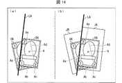
region specifying unit 233 has an end on the side where the virtual object is gripped. The determination area is set so that the portion extending from the end (upper end or upper right end) opposite to the portion (the lower end or the lower left end in the example of FIG. 11) toward the outside of the virtual object becomes wider. May be. In the virtual object, the other virtual hand can be brought close to the end opposite to the side gripped by one virtual hand without interfering with the one virtual hand. Can easily touch a virtual object held by one virtual hand.

(境界の特定例)
図12のステップS52では、たとえば、図14のような境界を特定してもよい。図14の例では、仮想オブジェクトOB(第2仮想オブジェクト)の上に仮想オブジェクトOA(第1仮想オブジェクト)が重なっている。仮想オブジェクトOAにおける仮想オブジェクトOBとの重畳部分Aは、線分Aa、Ab、Ac、Ad、およびAeで規定される五角形の領域である。
(Specific example of boundary)
In step S52 of FIG. 12, for example, a boundary as shown in FIG. 14 may be specified. In the example of FIG. 14, the virtual object OA (first virtual object) overlaps the virtual object OB (second virtual object). The overlapping portion A of the virtual object OA with the virtual object OB is a pentagonal region defined by line segments Aa, Ab, Ac, Ad, and Ae.

この例では、領域特定部233は、仮想オブジェクトOAの外形を規定する輪郭線のうち、仮想オブジェクトOAと仮想オブジェクトOBを区切る輪郭線(仮想カメラ1から見て仮想オブジェクトOBに重畳する線分)、すなわち線分Aa、Abを特定する。そして、領域特定部233は、図14の(a)に示すように、線分Aa、Abのうち、仮想オブジェクトOBとの重なり部分が最も長い線分Aaを含む直線LAを特定する。直線LAは、仮想オブジェクトOAの外形を構成する4辺のうち、左側の長辺を含む直線であるとも言える。そして、領域特定部233は、この直線LAを通る平面を判定領域JAと判定領域JBとの境界と特定する。この平面は、仮想カメラ1のロール方向(図3のw軸方向であり、基準視線5の方向でもある)と平行であることが望ましい。これにより、仮想カメラ1から仮想オブジェクトOAが見える部分には判定領域JAを設定し、仮想カメラ1から仮想オブジェクトOBが見える部分には判定領域JBを設定することができる。  In this example, theregion specifying unit 233 includes a contour line that divides the virtual object OA and the virtual object OB among the contour lines that define the outer shape of the virtual object OA (a line segment that is superimposed on the virtual object OB when viewed from the virtual camera 1). That is, line segments Aa and Ab are specified. Then, as illustrated in FIG. 14A, theregion specifying unit 233 specifies a straight line LA including the line segment Aa having the longest overlapping portion with the virtual object OB among the line segments Aa and Ab. It can be said that the straight line LA is a straight line including the left long side among the four sides constituting the outer shape of the virtual object OA. Then, thearea specifying unit 233 specifies a plane passing through the straight line LA as a boundary between the determination area JA and the determination area JB. This plane is preferably parallel to the roll direction of the virtual camera 1 (the w-axis direction in FIG. 3 and also the direction of the reference line of sight 5). Thereby, the determination area JA can be set in a portion where the virtual object OA can be seen from thevirtual camera 1, and the determination area JB can be set in a portion where the virtual object OB can be seen from thevirtual camera 1.

境界を特定した領域特定部233は、図14の(b)に示すように、仮想オブジェクトOAの周囲全周に特定されていた判定領域JA(図13参照)のうち、直線LAよりも左側(仮想オブジェクトOAの外側)の部分を排除する。つまり、領域特定部233には、直線LAよりも左側の部分は判定領域JAではないとみなす。これにより、判定領域JAは、直線LAよりも右側(仮想オブジェクトOA側)の部分が残る。つまり、領域特定部233は、仮想カメラ1から見て重畳部分Aに重畳する判定領域は、仮想オブジェクトOBよりも前面に位置する仮想オブジェクトOAの判定領域JA(第1領域)に設定する。このようにして設定された判定領域JAは、仮想カメラ1から見た平面内において、直線LAよりも仮想オブジェクトOB側には重畳していない。  As shown in FIG. 14B, thearea specifying unit 233 that specified the boundary is on the left side of the straight line LA in the determination area JA (see FIG. 13) specified on the entire circumference of the virtual object OA (see FIG. 13). The portion outside the virtual object OA is excluded. That is, thearea specifying unit 233 considers that the portion on the left side of the straight line LA is not the determination area JA. As a result, the determination area JA has a portion on the right side of the straight line LA (on the virtual object OA side). In other words, thearea specifying unit 233 sets the determination area superimposed on the overlapping portion A when viewed from thevirtual camera 1 to the determination area JA (first area) of the virtual object OA located in front of the virtual object OB. The determination area JA set in this way is not superimposed on the virtual object OB side with respect to the straight line LA in the plane viewed from thevirtual camera 1.

一方、領域特定部233は、仮想オブジェクトOBの判定領域JBについては、直線LAよりも右側(重畳部分A側)の部分を排除する。つまり、領域特定部233は、直線LAよりも右側の部分は判定領域JBではないとみなす。これにより、判定領域JBには、直線LAよりも左側(仮想オブジェクトOB側)の部分が残る。つまり、領域特定部233は、仮想オブジェクトOAよりも背後に位置する仮想オブジェクトOBについては、仮想カメラ1から見て重畳部分Aに重畳しない判定領域JB(第2領域)を設定する。このようにして設定された判定領域JBは、仮想カメラ1から見た平面内において、直線LAよりも仮想オブジェクトOA側には重畳していない。  On the other hand, for the determination area JB of the virtual object OB, thearea specifying unit 233 excludes a portion on the right side (superimposed portion A side) of the straight line LA. That is, thearea specifying unit 233 considers that the portion on the right side of the straight line LA is not the determination area JB. As a result, a portion on the left side (the virtual object OB side) of the straight line LA remains in the determination area JB. That is, thearea specifying unit 233 sets a determination area JB (second area) that does not overlap the overlapping portion A when viewed from thevirtual camera 1 for the virtual object OB located behind the virtual object OA. The determination area JB set in this way is not superimposed on the virtual object OA side with respect to the straight line LA in the plane viewed from thevirtual camera 1.

このように、領域特定部233は、複数の仮想オブジェクトが重なっている場合に、それら複数の仮想オブジェクトの判定領域が重畳しないように調整するので、ユーザは意図通りの仮想オブジェクトを直感的に選択することができる。  As described above, when a plurality of virtual objects are overlapped, thearea specifying unit 233 adjusts the determination areas of the plurality of virtual objects so as not to overlap, so the user intuitively selects a virtual object as intended. can do.

図14の例では、線分Abを通る境界は特定していないが、領域特定部233は、線分Abを通る境界を特定してもよい。図15の例では、図15の(a)に示すように、領域特定部233は、線分Aaを通る半直線LBと、線分Abを通る半直線LCを境界としている。この場合、図15の(b)に示すように、領域特定部233は、仮想オブジェクトOAの判定領域JAのうち、半直線LBよりも左側の部分と、半直線LCよりも下側の部分は排除し、半直線LBよりも右側かつ半直線LCよりも上側の部分を残している。一方、領域特定部233は、仮想オブジェクトOBの判定領域JBについては、半直線LBよりも右側の部分と、半直線LCよりも上側の部分は排除し、半直線LBよりも左側かつ半直線LCよりも下側の部分を残している。  In the example of FIG. 14, the boundary passing through the line segment Ab is not specified, but theregion specifying unit 233 may specify the boundary passing through the line segment Ab. In the example of FIG. 15, as illustrated in FIG. 15A, theregion specifying unit 233 uses a half line LB passing through the line segment Aa and a half line LC passing through the line segment Ab as a boundary. In this case, as shown in FIG. 15B, thearea specifying unit 233 determines that the part on the left side of the half line LB and the part below the half line LC in the determination area JA of the virtual object OA. This eliminates a portion on the right side of the half line LB and on the upper side of the half line LC. On the other hand, for the determination area JB of the virtual object OB, thearea specifying unit 233 excludes the part on the right side of the half line LB and the part on the upper side of the half line LC, and the left side of the half line LB and the half line LC. Leave the lower part than.

図14の例は、図15の例と比べて境界の数が少ないため、判定領域の特定に要する演算処理の負荷が少なく済むという利点がある。一方、図15の例は、図14の例と比べて、仮想オブジェクトOBについて、その上方や側方から仮想手を近付けて選択することが容易になると共に、その下方から仮想手を近付けて選択することも容易になるという利点がある。なお、図11の例のように、その下側を仮想左手OLで把持した仮想オブジェクトOAおよび仮想オブジェクトOBを仮想右手で選択する場合、これらの仮想オブジェクトの下方の判定領域は、仮想左手OLの位置と重なるため重要度が低い。このため、この場合には、図14の例のように、仮想オブジェクトOAの下側の短辺に沿った境界の特定は行わないことが好ましい。  The example in FIG. 14 has an advantage that the number of boundaries is smaller than that in the example in FIG. On the other hand, in the example of FIG. 15, compared to the example of FIG. 14, it becomes easier to select the virtual object OB by approaching the virtual hand from the upper side or the side and selecting the virtual hand from the lower side. There is an advantage that it is also easy to do. In addition, when the virtual object OA and the virtual object OB grasped by the virtual left hand OL are selected with the virtual right hand as in the example of FIG. 11, the determination area below these virtual objects is the virtual left hand OL. Less important because of overlapping position. Therefore, in this case, it is preferable not to specify the boundary along the short side below the virtual object OA as in the example of FIG.

(判定領域の設定例(重複排除後))
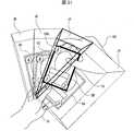
図16には、広げた状態で仮想左手OLに把持されたカード型の仮想オブジェクトOA〜ODについて、領域特定部233が判定領域JA〜JDを設定した例を示している。仮想オブジェクトOAは、4つの仮想オブジェクトのうち、最も手前(仮想カメラ1側)に位置しており、仮想オブジェクトOB、OC、ODの順で位置が奥側(仮想カメラ1から遠い側)となる。
(Judgment area setting example (after deduplication))
FIG. 16 shows an example in which thearea specifying unit 233 sets the determination areas JA to JD for the card-type virtual objects OA to OD held by the virtual left hand OL in an unfolded state. The virtual object OA is located on the foremost side (thevirtual camera 1 side) of the four virtual objects, and the position is the rear side (the side far from the virtual camera 1) in the order of the virtual objects OB, OC, and OD. .

この例では、領域特定部233は、仮想オブジェクトOAと仮想オブジェクトOBの境界を、仮想オブジェクトOAの左側の長辺を通る平面と特定し、該平面より右側の領域を仮想オブジェクトOAの判定領域JAに設定する。また、領域特定部233は、仮想オブジェクトOBと仮想オブジェクトOCの境界を、仮想オブジェクトOBの左側の長辺を通る平面と特定し、該平面より右側であり、かつ仮想オブジェクトOAと仮想オブジェクトOBの境界である平面よりも左側の領域を仮想オブジェクトOBの判定領域JBに設定する。領域特定部233は、仮想オブジェクトOCについても同様に、仮想オブジェクトOCの左側の長辺を通る平面より右側であり、かつ仮想オブジェクトOBと仮想オブジェクトOCの境界である平面よりも左側の領域を仮想オブジェクトOCの判定領域JCに設定する。領域特定部233は、仮想オブジェクトODについては、仮想オブジェクトOCと仮想オブジェクトODの境界である平面よりも左側の領域を仮想オブジェクトODの判定領域JDに設定する。なお、判定領域間の境界となる前記平面は、前述のように、仮想カメラ1のロール方向(図3のw軸方向であり、基準視線5の方向でもある)と平行であることが望ましい。  In this example, thearea specifying unit 233 specifies the boundary between the virtual object OA and the virtual object OB as a plane passing through the left long side of the virtual object OA, and determines the area on the right side of the plane as the determination area JA of the virtual object OA. Set to. Further, thearea specifying unit 233 specifies the boundary between the virtual object OB and the virtual object OC as a plane passing through the long side on the left side of the virtual object OB, and is on the right side of the plane and between the virtual object OA and the virtual object OB. The area on the left side of the plane that is the boundary is set as the determination area JB of the virtual object OB. Similarly, for the virtual object OC, theregion specifying unit 233 also virtualizes the region on the right side of the plane passing through the left long side of the virtual object OC and on the left side of the plane that is the boundary between the virtual object OB and the virtual object OC. Set in the determination area JC of the object OC. For the virtual object OD, thearea specifying unit 233 sets the area on the left side of the plane that is the boundary between the virtual object OC and the virtual object OD as the determination area JD of the virtual object OD. Note that, as described above, it is desirable that the plane serving as the boundary between the determination areas is parallel to the roll direction of the virtual camera 1 (the w-axis direction in FIG. 3 and the direction of the reference line of sight 5).

ユーザは、右コントローラ320の現実空間における位置を移動させることにより、仮想空間2における仮想右手ORを移動させることができる。そして、ユーザは、仮想右手ORを仮想オブジェクトOA〜ODのうち所望の仮想オブジェクトに近付けて、仮想オブジェクトを掴む操作を右コントローラ320に対して行うことにより、所望の仮想オブジェクトを選択することができる。  The user can move the virtual right hand OR in thevirtual space 2 by moving the position of theright controller 320 in the real space. Then, the user can select the desired virtual object by moving the virtual right hand OR closer to the desired virtual object among the virtual objects OA to OD and performing an operation for grasping the virtual object on theright controller 320. .

(仮想オブジェクトを選択する際の処理)
領域特定部233が判定領域を設定した後、ユーザが仮想オブジェクトを選択する際の処理を図17に基づいて説明する。ステップS60において、接触判定部234は、仮想オブジェクトを選択するために使用する仮想手について、仮想オブジェクトとの接触を判定するための付随オブジェクトを生成する。たとえば、図16の例のように、仮想右手ORで仮想オブジェクトOA〜ODのいずれかを選択する場合には、接触判定部234は、仮想右手ORとオブジェクトOA〜ODとの接触を判定するための付随オブジェクトを生成する。付随オブジェクトは、仮想空間2において仮想手と連動して移動する仮想オブジェクトであり、その詳細は図18および図19に基づいて後述する。
(Process when selecting virtual object)
A process when the user selects a virtual object after thearea specifying unit 233 sets the determination area will be described with reference to FIG. In step S60, thecontact determination unit 234 generates an accompanying object for determining contact with the virtual object for the virtual hand used for selecting the virtual object. For example, as in the example of FIG. 16, when selecting any of the virtual objects OA to OD with the virtual right hand OR, thecontact determination unit 234 determines contact between the virtual right hand OR and the objects OA to OD. Create an associated object of. The accompanying object is a virtual object that moves in conjunction with the virtual hand in thevirtual space 2, and details thereof will be described later with reference to FIGS. 18 and 19.

ステップS61において、コントローラセンサ140は、右コントローラ320の位置および傾き、ならびに、左コントローラ330の位置および傾きをそれぞれ検出する。ステップS62において、コントローラセンサ140は、各検出値を制御回路部200に送信する。コントローラ検出部213は、これらの検出値を受信する。  In step S61, thecontroller sensor 140 detects the position and inclination of theright controller 320 and the position and inclination of theleft controller 330, respectively. In step S <b> 62, thecontroller sensor 140 transmits each detection value to thecontrol circuit unit 200. Thecontroller detection unit 213 receives these detection values.

ステップS63において、仮想手制御部232は、受信した各検出値を用いて、ユーザの各仮想手(仮想右手および仮想左手)の仮想空間2における位置および傾きを更新する。具体的には、仮想空間2における仮想右手の位置を、グローバル座標系における右コントローラ320の現在位置に更新する。また、仮想手制御部232は、右コントローラ320の傾きの検出値に基づき、仮想空間2内における仮想右手の傾きを更新する。同様に、仮想手制御部232は、左コントローラ330の各検出値に基づき、仮想空間2における仮想左手の位置および傾きを更新する。さらに、接触判定部234は、仮想手の位置と連動するように付随オブジェクトの位置を更新する。ステップS64において、視界画像生成部223は、仮想手の位置および傾きが更新された視界画像を生成してHMD110に出力し、ステップS65において、HMD110は、受信した視界画像をディスプレイ112に表示し、これによりユーザが視認する視界画像が更新される。  In step S63, the virtualhand control unit 232 updates the position and inclination of each virtual hand (virtual right hand and virtual left hand) of the user in thevirtual space 2 using each received detection value. Specifically, the position of the virtual right hand in thevirtual space 2 is updated to the current position of theright controller 320 in the global coordinate system. Further, the virtualhand control unit 232 updates the virtual right hand tilt in thevirtual space 2 based on the detected tilt value of theright controller 320. Similarly, the virtualhand control unit 232 updates the position and inclination of the virtual left hand in thevirtual space 2 based on each detection value of theleft controller 330. Further, thecontact determination unit 234 updates the position of the accompanying object so as to be interlocked with the position of the virtual hand. In step S64, the visual field image generation unit 223 generates a visual field image in which the position and inclination of the virtual hand are updated and outputs the visual field image to theHMD 110. In step S65, theHMD 110 displays the received visual field image on thedisplay 112, Thereby, the field-of-view image visually recognized by the user is updated.

ステップS66において、接触判定部234は、付随オブジェクトが仮想オブジェクトの判定領域に入っているか否かを判定する。接触判定部234が、付随オブジェクトは判定領域に入っていないと判定した場合(ステップS66においてNO)、処理はステップS61に戻る。一方、接触判定部234が付随オブジェクトが判定領域に入っていると判定した場合(ステップS66においてYES)、コントローラ300がステップS67において検出し、ステップS68において送信した、各ボタンの押下状態を示す各検出値に基づき、掴む操作を検出したか否かを判定する(ステップS69)。どのような操作を掴む操作とするかは特に限定されないが、たとえば仮想手の親指と、人差し指および中指とが接触するまで各指に対応するボタンを押下する操作を掴む操作としてもよい。  In step S <b> 66, thecontact determination unit 234 determines whether the accompanying object is in the virtual object determination region. Ifcontact determination unit 234 determines that the accompanying object is not in the determination region (NO in step S66), the process returns to step S61. On the other hand, whencontact determination unit 234 determines that the accompanying object is in the determination area (YES in step S66), eachcontroller 300 detects in step S67 and transmits in step S68, indicating the pressed state of each button. Based on the detected value, it is determined whether or not a gripping operation has been detected (step S69). There is no particular limitation on what kind of operation is to be grasped, but for example, an operation of pressing a button corresponding to each finger until the thumb of the virtual hand contacts the index finger and the middle finger may be grasped.

接触判定部234が掴む操作が行われていないと判定した場合(ステップS69においてNO)、処理はステップS61に戻る。一方、接触判定部234は、掴む操作が行われたと判定した場合(ステップS69においてYES)、付随オブジェクトが複数の仮想オブジェクトの判定領域に入っているか否かを判定する(ステップS70)。また、仮想手制御部232は、仮想空間26において、仮想手に掴む動作を実行させる。なお、図示を省略しているが、仮想手による掴む動作は視界画像26に反映される。  If it is determined that the operation for gripping bycontact determination unit 234 has not been performed (NO in step S69), the process returns to step S61. On the other hand, when thecontact determination unit 234 determines that the gripping operation has been performed (YES in step S69), thecontact determination unit 234 determines whether the accompanying object is in the determination area of the plurality of virtual objects (step S70). In addition, the virtualhand control unit 232 causes thevirtual hand 26 to perform an operation of grasping the virtual hand. Although illustration is omitted, the grasping operation by the virtual hand is reflected in theview field image 26.

付随オブジェクトが複数の判定領域に入っていると判定した場合(ステップS70においてYES)、接触判定部234は、当該複数の判定領域のうち、付随オブジェクトとの重なり体積がより大きい判定領域を特定する。なお、前記重なり体積は、付随オブジェクトの内部であり、かつ判定領域の内部である領域の体積である。たとえば、接触判定部234は、付随オブジェクトの一部が第1の判定領域に含まれ、他の一部が第2の判定領域に含まれている場合、第1の判定領域に含まれる前記一部と、第2の判定領域に含まれる前記他の一部のいずれの体積が大きいかを判定する。  When it is determined that the accompanying object is in a plurality of determination areas (YES in step S70), thecontact determination unit 234 specifies a determination area having a larger overlapping volume with the accompanying object from among the plurality of determination areas. . The overlapping volume is a volume of an area that is inside the associated object and inside the determination area. For example, when a part of the accompanying object is included in the first determination area and the other part is included in the second determination area, thecontact determination unit 234 includes the one included in the first determination area. It is determined which volume of the part and the other part included in the second determination region is larger.

そして、重なり体積がより大きいと特定した判定領域に対応する仮想オブジェクトが掴まれたと判定する(ステップS71)。一方、付随オブジェクトが1つの判定領域に入っていると判定した場合(ステップS70においてNO)、接触判定部234は、当該判定領域に対応する仮想オブジェクトが掴まれたと判定し(ステップS72)、当該仮想オブジェクトと、当該付随オブジェクトに対応する仮想手とを関連付ける。たとえば、掴まれた仮想オブジェクトと、掴んだ仮想手とを関連付けて、仮想手が移動したときには仮想オブジェクトも仮想手と連動して移動させてもよい。  And it determines with the virtual object corresponding to the determination area | region specified that the overlapping volume was larger being grasped (step S71). On the other hand, when it is determined that the accompanying object is in one determination area (NO in step S70), thecontact determination unit 234 determines that the virtual object corresponding to the determination area is grasped (step S72), and The virtual object is associated with the virtual hand corresponding to the accompanying object. For example, the grasped virtual object may be associated with the grasped virtual hand, and the virtual object may be moved in conjunction with the virtual hand when the virtual hand moves.

ステップS73において、コントローラ300は、各ボタンの押下状態を示す各検出値を検出する。ステップS74において、コントローラ300は、各検出値を制御回路部200に送信する。ステップS75において、接触判定部234は、各ボタンの押下状態を示す各検出値に基づき、掴み状態が解除されたか否かを判定する。たとえば仮想オブジェクトを掴んでいる状態(たとえば仮想手の親指と、人差し指および中指とが接している状態)において、仮想手の親指と、人差し指および中指とが離れるまで各指に対応するボタンの押下状態を「0」に近付ける(曲げていた仮想手の指を伸ばす)操作を、掴み状態を解除する操作としてもよい。  In step S73, thecontroller 300 detects each detection value indicating the pressed state of each button. In step S <b> 74, thecontroller 300 transmits each detection value to thecontrol circuit unit 200. In step S <b> 75, thecontact determination unit 234 determines whether or not the gripping state has been released based on each detection value indicating the pressed state of each button. For example, in a state where a virtual object is being grasped (for example, a state where the thumb of a virtual hand is in contact with an index finger and a middle finger), the button corresponding to each finger is pressed until the thumb of the virtual hand is separated from the index finger and the middle finger. The operation of bringing the position close to “0” (extending the finger of the bent virtual hand) may be an operation for releasing the gripping state.

接触判定部234が、掴み状態が維持されていると判定した場合(ステップS75においてNO)、処理はステップS73に戻る。一方、接触判定部234は、掴み状態が解除されたと判定した場合(ステップS75においてYES)、仮想オブジェクトが仮想手から離されたと判定し(ステップS76)、当該仮想オブジェクトと当該付随オブジェクトに対応する仮想手との関連付けを解消する。また、仮想手制御部232は、仮想空間26において、仮想手に掴んでいた仮想オブジェクトを離す動作を実行させる。なお、図示を省略しているが、仮想手による仮想オブジェクトを離す動作は視界画像26に反映される。仮想オブジェクトが離されたと判定した後の処理は、ゲーム内容に応じたものとすればよい。たとえば、視界画像生成部223は、一方の仮想手に掴まれており、当該仮想手から離された仮想オブジェクトが、再度、他方の仮想手(仮想オブジェクトがセットされた側の仮想手)上に戻る動画像を視界画像26としてHMD110に表示させてもよい。この後、処理はステップS61に戻ってもよい。  Ifcontact determination unit 234 determines that the gripping state is maintained (NO in step S75), the process returns to step S73. On the other hand, whencontact determination section 234 determines that the grip state has been released (YES in step S75), it determines that the virtual object has been released from the virtual hand (step S76), and corresponds to the virtual object and the associated object. Cancel the association with the virtual hand. In addition, the virtualhand control unit 232 causes thevirtual space 26 to perform an operation of releasing the virtual object held by the virtual hand. Although not shown, the movement of releasing the virtual object by the virtual hand is reflected in theview image 26. The processing after determining that the virtual object has been released may be in accordance with the content of the game. For example, the visual field image generation unit 223 is grasped by one virtual hand, and the virtual object separated from the virtual hand is again placed on the other virtual hand (the virtual hand on the side where the virtual object is set). The returning moving image may be displayed on theHMD 110 as theview image 26. Thereafter, the process may return to step S61.

(付随オブジェクトの例)
図18には、仮想オブジェクトOA、OBとこれらの判定領域JA、JBを図示すると共に、仮想右手ORの付随オブジェクトORAを図示している。仮想オブジェクトOA、OBを把持する仮想左手OLは図示を省略している。なお、視界画像生成部223が付随オブジェクトORAを含む視界画像26を生成する必要はなく、接触判定部234が付随オブジェクトORAの位置および範囲を特定していればよい。また、図18では、仮想右手ORの付随オブジェクトORAを例示しているが、仮想左手OLによって仮想オブジェクトを選択する場合には、接触判定部234が、付随オブジェクトORAと同様にして、仮想左手OLに対応する付随オブジェクトを生成する。後述の図19および図20の例においても同様である。
(Example of accompanying objects)
FIG. 18 illustrates the virtual objects OA and OB and the determination areas JA and JB, and the accompanying object ORA of the virtual right hand OR. The virtual left hand OL that holds the virtual objects OA and OB is not shown. The view image generation unit 223 does not need to generate theview image 26 including the accompanying object ORA, and thecontact determination unit 234 only needs to specify the position and range of the accompanying object ORA. 18 illustrates the accompanying object ORA of the virtual right hand OR, but when the virtual object is selected by the virtual left hand OL, thecontact determination unit 234 performs the virtual left hand OL in the same manner as the accompanying object ORA. An associated object corresponding to is generated. The same applies to the examples of FIGS. 19 and 20 described later.

付随オブジェクトORAは、球体状のオブジェクトであり、接触判定部234は、仮想右手ORと付随オブジェクトORAが所定の位置関係となるような位置に付随オブジェクトORAを生成する。なお、付随オブジェクトORAの形状は特に限定されず、たとえば多面体であってもよい。付随オブジェクトORAの初期位置は、仮想右手ORの位置に基づいて特定することができる。たとえば、接触判定部234は、仮想右手ORの腕の延在方向に沿った位置であって、手首から所定距離の位置に付随オブジェクトORAを配置してもよい。  The accompanying object ORA is a spherical object, and thecontact determination unit 234 generates the accompanying object ORA at a position where the virtual right hand OR and the accompanying object ORA have a predetermined positional relationship. The shape of the accompanying object ORA is not particularly limited, and may be a polyhedron, for example. The initial position of the accompanying object ORA can be specified based on the position of the virtual right hand OR. For example, thecontact determination unit 234 may arrange the accompanying object ORA at a position along the extending direction of the arm of the virtual right hand OR and at a predetermined distance from the wrist.

また、接触判定部234は、仮想右手ORの位置が移動した場合には、移動後の仮想右手ORと付随オブジェクトORAの位置関係が、前記所定の位置関係となる状態を維持するように、付随オブジェクトORAの位置を更新する。これにより、図18に示すように、仮想右手ORの位置が移動した場合に、付随オブジェクトORAの位置もこれに連動して移動し、付随オブジェクトORAが仮想右手ORから一定の位置に配置された状態が維持される。  Further, when the position of the virtual right hand OR is moved, thecontact determination unit 234 maintains the state in which the positional relationship between the virtual right hand OR and the associated object ORA after the movement is in the predetermined positional relationship. Update the position of the object ORA. As a result, as shown in FIG. 18, when the position of the virtual right hand OR is moved, the position of the associated object ORA is also moved in conjunction therewith, and the associated object ORA is arranged at a certain position from the virtual right hand OR. State is maintained.

接触判定部234は、付随オブジェクトの位置を、仮想手の一部(たとえば指)を動かす動作に応じて移動させてもよいし、移動させなくてもよい。たとえば、図19に記載した、仮想右手ORと付随オブジェクトORAの例のうち、(a)の例では、仮想右手ORによって掴む動作が行われた場合に、接触判定部234は、仮想右手ORの指先の位置に連動して付随オブジェクトORAの位置を変化させている。言い換えれば、接触判定部234は、掴む動作中の仮想右手ORの動きに応じて、付随オブジェクトORAの位置を変動させている。一方、(b)の例では、接触判定部234は、仮想右手ORによる掴む動作の前後で付随オブジェクトORAの位置を維持させている。仮想右手ORで掴む動作を行うことによって仮想オブジェクトを選択する場合、掴む動作中に付随オブジェクトORAの位置を変化させないことが好ましい。掴む動作中に付随オブジェクトの位置が変わると、選択対象の仮想オブジェクトがユーザの意図に反して変わってしまう可能性があるからである。一方、仮想右手ORの指先で摘む動作を行うことによって仮想オブジェクトを選択する場合には、仮想右手ORの指先の位置に連動して付随オブジェクトORAの位置を変化させることが好ましい。また、接触判定部234は、(c)の例のように、仮想右手ORの内部に付随オブジェクトORAを配置してもよい。仮想右手ORの内部領域のうち、いずれの位置に付随オブジェクトORAを配置するかは特に限定されないが、接触判定部234は、たとえば仮想右手ORの内部領域のうち指先の位置に付随オブジェクトORAを配置してもよい。この場合、接触判定部234は、仮想右手ORの指先の微妙な動きに応じた接触判定を行うことができる。さらに、ユーザが視認できる仮想右手ORの指先部分を接触判定部234が接触判定に用いることになるから、ユーザは直感的に仮想オブジェクトを選択することが可能になる。これらの例は、仮想右手ORの一部を、仮想オブジェクトとの接触を判定するための判定領域とした例であるとも言える。また、接触判定部234は、付随オブジェクトORAの一部が仮想右手ORの内部となり、他の一部が仮想右手ORAの外部となる位置に付随オブジェクトORAを配置してもよい。  Thecontact determination unit 234 may or may not move the position of the accompanying object according to an operation of moving a part of the virtual hand (for example, a finger). For example, in the example of (a) in the example of the virtual right hand OR and the accompanying object ORA described in FIG. 19, when an operation of grasping with the virtual right hand OR is performed, thecontact determination unit 234 displays the virtual right hand OR. The position of the accompanying object ORA is changed in conjunction with the position of the fingertip. In other words, thecontact determination unit 234 changes the position of the associated object ORA according to the movement of the virtual right hand OR during the grasping operation. On the other hand, in the example of (b), thecontact determination unit 234 maintains the position of the accompanying object ORA before and after the grasping motion by the virtual right hand OR. When a virtual object is selected by performing an operation of grasping with the virtual right hand OR, it is preferable that the position of the accompanying object ORA is not changed during the grasping operation. This is because if the position of the accompanying object changes during the grasping operation, the virtual object to be selected may change against the user's intention. On the other hand, when a virtual object is selected by performing a picking operation with the fingertip of the virtual right hand OR, it is preferable to change the position of the accompanying object ORA in conjunction with the position of the fingertip of the virtual right hand OR. Moreover, thecontact determination part 234 may arrange | position the accompanying object ORA in the inside of virtual right hand OR like the example of (c). There is no particular limitation as to which position in the inner area of the virtual right hand OR the associated object ORA is disposed, but thecontact determination unit 234 arranges the associated object ORA at the position of the fingertip in the inner area of the virtual right hand OR, for example. May be. In this case, thecontact determination unit 234 can perform contact determination according to the delicate movement of the fingertip of the virtual right hand OR. Furthermore, since thecontact determination unit 234 uses the fingertip portion of the virtual right hand OR that can be visually recognized by the user for contact determination, the user can intuitively select a virtual object. It can be said that these examples are examples in which a part of the virtual right hand OR is used as a determination region for determining contact with the virtual object. Further, thecontact determination unit 234 may arrange the accompanying object ORA at a position where a part of the accompanying object ORA is inside the virtual right hand OR and the other part is outside the virtual right hand ORA.

(付随オブジェクトが複数の判定領域に入った場合の判定の例)
図20には、仮想オブジェクトOA、OBとこれらの判定領域JA、JBを図示するとともに、仮想右手ORの付随オブジェクトORAを図示している。仮想オブジェクトOA、OBを把持する仮想左手OLと、付随オブジェクトORAに対応する仮想右手ORは図示を省略している。この例では、付随オブジェクトORAは、判定領域JA、JBの両方に入っているので、図17のステップS71で説明したように、接触判定部234は、判定領域JAとJBのうち、付随オブジェクトORAとの重なり体積がより大きい判定領域を特定する。
(Example of judgment when accompanying objects are in multiple judgment areas)
FIG. 20 illustrates the virtual objects OA and OB and the determination areas JA and JB, and the accompanying object ORA of the virtual right hand OR. The virtual left hand OL that holds the virtual objects OA and OB and the virtual right hand OR corresponding to the accompanying object ORA are not shown. In this example, since the accompanying object ORA is in both the determination areas JA and JB, as described in step S71 of FIG. 17, thecontact determination unit 234 includes the accompanying object ORA in the determination areas JA and JB. A determination region having a larger overlap volume with is specified.

図20の例では、判定領域JAとJBの境界は、直線LAを通る平面であり、付随オブジェクトORAのうち、前記平面より左側の部分ORA1は判定領域JBに含まれており、前記平面より右側の部分ORA2は判定領域JAに含まれている。また、球体状の付随オブジェクトORAの中心をCで示している。この例では、接触判定部234は、部分ORA1と部分ORA2の体積をそれぞれ算出して、算出した体積を比較することにより、付随オブジェクトORAとの重なり体積がより大きい判定領域を特定することができる。  In the example of FIG. 20, the boundary between the determination areas JA and JB is a plane passing through the straight line LA, and among the accompanying objects ORA, the portion ORA1 on the left side of the plane is included in the determination area JB and is on the right side of the plane. The portion ORA2 is included in the determination area JA. The center of the spherical accompanying object ORA is indicated by C. In this example, thecontact determination unit 234 can specify a determination region having a larger overlap volume with the accompanying object ORA by calculating the volumes of the partial ORA1 and the partial ORA2 and comparing the calculated volumes. .

なお、図20の例では、直線LAを通る平面により球体状の付随オブジェクトORAが2つの部分ORA1、ORA2に切り分けられており、部分ORA1の全体が判定領域JBに含まれ、部分ORA2の全体が判定領域JAに含まれている。よって、接触判定部234は、付随オブジェクトORAの中心Cが該平面に対してどちらの判定領域側に位置しているかを判定することにより、付随オブジェクトORAとの重なり体積がより大きい判定領域を特定することができる。つまり、図示の例では、接触判定部234は、付随オブジェクトORAの中心Cが、直線LAを通る平面よりも左側(判定領域JB側)であることから、判定領域JBの方が、付随オブジェクトORAとの重なり体積がより大きいと特定することができる。このように、付随オブジェクトORAを球体状とすることにより、重なり体積のより大きい判定領域を簡易な演算で算出することができる場合がある。  In the example of FIG. 20, the spherical accompanying object ORA is divided into two parts ORA1 and ORA2 by a plane passing through the straight line LA, the whole part ORA1 is included in the determination area JB, and the whole part ORA2 is It is included in the determination area JA. Therefore, thecontact determination unit 234 determines a determination region having a larger overlap volume with the accompanying object ORA by determining which determination region side the center C of the accompanying object ORA is located with respect to the plane. can do. That is, in the illustrated example, thecontact determination unit 234 determines that the center C of the associated object ORA is on the left side (determination area JB side) with respect to the plane passing through the straight line LA. It can be specified that the overlapping volume is larger. Thus, by making the accompanying object ORA into a sphere shape, a determination region having a larger overlap volume may be calculated with a simple calculation.

なお、付随オブジェクトが3つ以上の判定領域に入っている場合には、接触判定部234は、付随オブジェクトと各判定領域との重なり体積をそれぞれ算出することにより、重なり体積が最も大きい判定領域を特定することができる。また、接触判定部234は、付随オブジェクトを用いずに仮想オブジェクトと仮想手との接触を判定してもよい。この場合、仮想手が複数の仮想オブジェクトの判定領域に入っていれば、接触判定部234は、仮想手と各仮想オブジェクトとの重なり体積をそれぞれ算出することにより、重なり体積が最も大きい判定領域を特定することができる。ただし、仮想手は形状が複雑な仮想オブジェクトであり、仮想手と判定領域の重なり体積の演算は複雑なものとなるから、演算量を少なく抑えるという観点からは、付随オブジェクトを用いた判定を採用することが好ましい。  When the accompanying object is in three or more determination areas, thecontact determination unit 234 calculates the overlapping volume between the accompanying object and each determination area, thereby determining the determination area having the largest overlapping volume. Can be identified. Thecontact determination unit 234 may determine contact between the virtual object and the virtual hand without using the accompanying object. In this case, if the virtual hand is in the determination area of a plurality of virtual objects, thecontact determination unit 234 calculates the overlapping volume between the virtual hand and each virtual object, thereby determining the determination area having the largest overlapping volume. Can be identified. However, since the virtual hand is a virtual object with a complicated shape and the calculation of the overlapping volume of the virtual hand and the judgment area is complicated, the judgment using the accompanying object is adopted from the viewpoint of reducing the amount of computation. It is preferable to do.

(仮想オブジェクトが掴まれたと判定した場合の表示)
図17のステップS72において、接触判定部234が、仮想オブジェクトが掴まれたと判定した場合の表示について図21に基づいて説明する。図21の例では、仮想左手OLに4つのカードの仮想オブジェクトOA〜ODが把持されており、これら仮想オブジェクトの判定領域が、判定領域JA〜JDである。判定領域JAの左側の側面が、判定領域JAとJBの境界面であり、判定領域JBの左側の側面が、判定領域JBと判定領域JCとの境界面であり、判定領域JCの左側の側面が、判定領域JCと判定領域JDとの境界面である。また、仮想右手ORの近傍には付随オブジェクトORAが位置している。なお、判定領域JA〜JDと付随オブジェクトORAは、視界画像26として表示する必要はない。
(Display when it is determined that the virtual object is grabbed)
The display when thecontact determination unit 234 determines that the virtual object is grasped in step S72 of FIG. 17 will be described based on FIG. In the example of FIG. 21, virtual objects OA to OD of four cards are held by the virtual left hand OL, and the determination areas of these virtual objects are the determination areas JA to JD. The left side surface of the determination area JA is the boundary surface between the determination areas JA and JB, the left side surface of the determination area JB is the boundary surface between the determination area JB and the determination area JC, and the left side surface of the determination area JC. Is a boundary surface between the determination area JC and the determination area JD. An accompanying object ORA is positioned in the vicinity of the virtual right hand OR. Note that the determination areas JA to JD and the accompanying object ORA need not be displayed as theview image 26.

図示しない右コントローラ320によって掴む操作が行われたことにより、仮想右手ORは、仮想オブジェクトを掴んでいる形状(親指と中指とが接するまで指が折り曲げられた形状)となっている。仮想右手ORに付随する付随オブジェクトORAは、判定領域JBとJCの両方に含まれているが、判定領域JBとの重なり体積の方がより大きいため、この例では、接触判定部234は、仮想右手ORが仮想オブジェクトOBを掴んだと判定している。  As a result of the gripping operation performed by the right controller 320 (not shown), the virtual right hand OR has a shape of gripping the virtual object (a shape in which the finger is bent until the thumb and the middle finger come into contact). The accompanying object ORA associated with the virtual right hand OR is included in both the determination areas JB and JC, but since the overlapping volume with the determination area JB is larger, in this example, thecontact determination unit 234 includes the virtual object OR It is determined that the right hand OR has grasped the virtual object OB.

この場合、視界画像生成部223は、図示のように、掴んだと判定された仮想オブジェクトOBを、他の仮想オブジェクトOA、OC、ODよりも上方かつ、上面側に移動させた視界画像26を生成し、表示させてもよい。これにより、仮想オブジェクトOBが掴まれたことをユーザに明確に認識させることができ、また、仮想オブジェクトOBに記載された絵や文字などをユーザに確認させることができる。さらに、図示の例では、掴まれた仮想オブジェクトOBの周囲に枠線FRを表示しており、これにより、仮想オブジェクトOBが掴まれたことをユーザにより明確に認識させている。  In this case, as shown in the drawing, the visual field image generation unit 223 moves the virtual object OB determined to have been grabbed above the other virtual objects OA, OC, OD and to the upper surface side. It may be generated and displayed. As a result, the user can clearly recognize that the virtual object OB has been grasped, and the user can confirm the picture, character, or the like described in the virtual object OB. Further, in the example shown in the figure, a frame line FR is displayed around the grasped virtual object OB, thereby making it clear to the user that the virtual object OB has been grasped.

枠線FRは、付随オブジェクトが判定領域に入ったときに表示させてもよい。この場合、図17の処理では、接触判定部234が、付随オブジェクトが判定領域に入った(ステップS66でYES)と判定した後に、付随オブジェクトが複数の判定領域に入っているか否かを判定すればよい。そして、接触判定部234が、付随オブジェクトが複数の判定領域に入っていると判定した場合に、視界画像生成部223が、重なり体積がより大きい判定領域に対応する仮想オブジェクトに対して枠線FRが付された視界画像26を生成すればよい。この場合、ユーザは、所望の仮想オブジェクト上に枠線FRが表示されていることを確認した上で、仮想オブジェクトを掴む操作を行うことができるので、所望の仮想オブジェクトをより確実に掴むことができる。  The frame line FR may be displayed when the accompanying object enters the determination area. In this case, in the process of FIG. 17, after thecontact determination unit 234 determines that the accompanying object has entered the determination region (YES in step S66), it is determined whether or not the accompanying object is in a plurality of determination regions. That's fine. When thecontact determination unit 234 determines that the accompanying object is in a plurality of determination regions, the field-of-view image generation unit 223 applies the frame line FR to the virtual object corresponding to the determination region having a larger overlap volume. What is necessary is just to produce | generate thevisual field image 26 attached | subjected. In this case, since the user can perform an operation of grasping the virtual object after confirming that the frame FR is displayed on the desired virtual object, the user can grasp the desired virtual object more reliably. it can.

なお、仮想手により掴まれている仮想オブジェクト、あるいは掴む操作を行うことによって掴むことのできる仮想オブジェクトをユーザに識別させるための表示は、枠線FRの表示に限られない。また、図示の例では、仮想オブジェクトOBを最前面(仮想左手OLに把持された仮想オブジェクトのうち最も仮想カメラ1寄りの位置)に移動させているが、判定領域JBは移動前の状態から更新していない。これは、仮想オブジェクトOBが仮想右手ORに把持されている状態では、仮想オブジェクトとの接触判定を行う必要がないためである。判定領域の更新を必要最小限とすることにより、演算処理の負荷を低く抑えることができる。  Note that the display for identifying the virtual object that is grasped by the virtual hand or the virtual object that can be grasped by performing the grasping operation is not limited to the display of the frame FR. In the illustrated example, the virtual object OB is moved to the forefront (the position closest to thevirtual camera 1 among the virtual objects held by the virtual left hand OL), but the determination area JB is updated from the state before the movement. Not done. This is because it is not necessary to perform contact determination with the virtual object when the virtual object OB is held by the virtual right hand OR. By minimizing the update of the determination area, the processing load can be reduced.

〔変形例〕
本発明は上述した各実施形態に限定されるものではなく、請求項に示した範囲で種々の変更が可能である。異なる実施形態にそれぞれ開示された技術的手段を適宜組み合わせて得られる実施形態も、本発明の技術的範囲に含まれる。各実施形態にそれぞれ開示された技術的手段を組み合わせることによって、新しい技術的特徴を形成することもできる。
[Modification]
The present invention is not limited to the above-described embodiments, and various modifications can be made within the scope of the claims. Embodiments obtained by appropriately combining technical means disclosed in different embodiments are also included in the technical scope of the present invention. A new technical feature can also be formed by combining the technical means disclosed in each embodiment.

前記実施形態では、領域特定部233が、各仮想オブジェクトに判定領域を設定した後、設定した判定領域間で重畳部分が生じないように調整する(重畳部分を排除する)例を示したが、重畳しない判定領域を設定する方法はこの例に限られない。例えば、領域特定部233は、まず仮想オブジェクト間の境界を特定し、特定した境界を超えないように(各仮想オブジェクトについて、仮想カメラ1から見える部分から判定領域を延在させ、他の仮想オブジェクト上には延在させないように)各仮想オブジェクトの判定領域を設定してもよい。  In the above-described embodiment, theregion specifying unit 233 sets the determination region for each virtual object, and then performs an adjustment so as not to generate the overlapping portion between the set determination regions (excludes the overlapping portion). The method for setting the determination region that is not superimposed is not limited to this example. For example, thearea specifying unit 233 first specifies the boundary between the virtual objects, and extends the determination area from the portion visible to thevirtual camera 1 so as not to exceed the specified boundary. A determination area for each virtual object may be set (so as not to extend upward).

ユーザが操作する仮想オブジェクトは、ユーザの頭部以外の身体の一部の動きに連動して仮想空間2内を移動するものであればよく、仮想手に限られない。たとえば、仮想空間2内の敵キャラクタ(仮想オブジェクト)と、武器を使って戦うゲームであれば、武器がユーザの操作する仮想オブジェクトとなる。  The virtual object operated by the user is not limited to a virtual hand as long as it moves in thevirtual space 2 in conjunction with the movement of a part of the body other than the user's head. For example, in the case of a game in which an enemy character (virtual object) in thevirtual space 2 fights with a weapon, the weapon becomes a virtual object operated by the user.

どのような仮想オブジェクトの判定領域を特定するかも特に限定されず、仮想空間2中の全ての仮想オブジェクトの判定領域を特定してもよいし、一部の仮想オブジェクトの判定領域を特定してもよい。また、仮想オブジェクトの形状も特に限定されない。なお、仮想空間2に占める体積が大きい仮想オブジェクトは、判定領域を特定するまでもなくユーザが容易に選択できるので、体積が閾値以下の仮想オブジェクト、あるいは厚さが閾値以下の仮想オブジェクトについてのみ判定領域を特定してもよい。  There is no particular limitation as to what virtual object determination area is specified, and all virtual object determination areas in thevirtual space 2 may be specified, or some virtual object determination areas may be specified. Good. Further, the shape of the virtual object is not particularly limited. Note that a virtual object occupying a large volume in thevirtual space 2 can be easily selected by the user without specifying a determination area, so only a virtual object whose volume is equal to or smaller than a threshold value or a virtual object whose thickness is equal to or smaller than a threshold value is determined. An area may be specified.

また、仮想オブジェクトとの接触による操作をMR等に適用することによって仮想体験を提供する場合には、操作対象オブジェクトに換えてユーザの実際の頭部以外の身体の一部を物理的・光学的手法等によって検知し、当該身体の一部と仮想オブジェクトの位置関係に基づいて、当該身体の一部と仮想オブジェクトとの接触を判定してもよい。なお、透過型HMDを用いて仮想体験を提供する場合には、ユーザの基準視線は、非透過型HMDと同様に、HMDの動き、または、ユーザの視線を検知することによって特定してもよい。仮想オブジェクトに対する判定領域の設定方法、および設定した判定領域に基づく、ユーザの体の一部と仮想オブジェクトと接触の判定方法等は上記実施形態で説明した方法と同様である。  In addition, when a virtual experience is provided by applying an operation by contact with a virtual object to MR or the like, a part of the body other than the actual head of the user is physically and optically replaced with the operation target object. The contact between the body part and the virtual object may be determined based on the positional relationship between the body part and the virtual object. When providing a virtual experience using a transmissive HMD, the user's reference line of sight may be specified by detecting the movement of the HMD or the user's line of sight, similar to the non-transmissive HMD. . A method for setting a determination area for a virtual object, a method for determining a contact between a part of a user's body and a virtual object based on the set determination area, and the like are the same as those described in the above embodiment.

〔ソフトウェアによる実現例〕
制御回路部200の制御ブロック(検出部210、表示制御部220、仮想空間制御部230、記憶部240、および通信部250)は、集積回路(ICチップ)等に形成された論理回路(ハードウェア)によって実現してもよいし、CPUを用いてソフトウェアによって実現してもよい。
[Example of software implementation]
A control block (detection unit 210,display control unit 220, virtualspace control unit 230,storage unit 240, and communication unit 250) of thecontrol circuit unit 200 is a logic circuit (hardware) formed in an integrated circuit (IC chip) or the like. ) Or by software using a CPU.

後者の場合、制御ブロックは、各機能を実現するソフトウェアであるプログラムの命令を実行するCPU、前記プログラムおよび各種データがコンピュータ(又はCPU)で読み取り可能に記録されたROMまたは記憶装置(これらを「記録媒体」と称する)、前記プログラムを展開するRAM等を備えている。そして、コンピュータ(又はCPU)が前記プログラムを前記記録媒体から読み取って実行することにより、本発明の目的が達成される。前記記録媒体としては、「一時的でない有形の媒体」、たとえば、テープ、ディスク、カード、半導体メモリ、プログラマブルな論理回路等を用いることができる。また、前記プログラムは、該プログラムを伝送可能な任意の伝送媒体(通信ネットワークや放送波等)を介して前記コンピュータに供給されてもよい。なお、本発明は、前記プログラムが電子的な伝送によって具現化された、搬送波に埋め込まれたデータ信号の形態でも実現され得る。  In the latter case, the control block includes a CPU that executes instructions of a program that is software that implements each function, a ROM or a storage device in which the program and various data are recorded so as to be readable by a computer (or CPU) And a RAM for developing the program. And the objective of this invention is achieved when a computer (or CPU) reads the said program from the said recording medium and runs it. As the recording medium, a “non-temporary tangible medium” such as a tape, a disk, a card, a semiconductor memory, a programmable logic circuit, or the like can be used. The program may be supplied to the computer via an arbitrary transmission medium (such as a communication network or a broadcast wave) that can transmit the program. The present invention can also be realized in the form of a data signal embedded in a carrier wave, in which the program is embodied by electronic transmission.

〔付記事項〕
本発明の一側面にかかる内容を列記すると以下の通りである。
[Additional Notes]
The contents according to one aspect of the present invention are listed as follows.

(項目1)頭部にヘッドマウントディスプレイを装着したユーザに仮想空間を提供する方法であって、前記仮想空間に配置された、第1仮想オブジェクトおよび第2仮想オブジェクトを少なくとも含む複数の仮想オブジェクトを特定するとともに、前記ユーザの頭部以外の身体の一部の動きに連動して動作する操作対象オブジェクトを前記仮想空間に配置するステップと、前記第1仮想オブジェクトと前記操作対象オブジェクトとの接触を判定するための、前記第1仮想オブジェクトに関連付けられる第1領域と、前記第2仮想オブジェクトと前記操作対象オブジェクトとの接触を判定するための、前記第2仮想オブジェクトに関連付けられる第2領域とをそれぞれ設定するステップと、前記操作対象オブジェクトまたは前記操作対象オブジェクトに付随する付随オブジェクトのうち前記第1領域に含まれる第1部分が、前記操作対象オブジェクトまたは前記付随オブジェクトのうち前記第2領域に含まれる第2部分よりも大きい場合、前記操作対象オブジェクトが前記第1仮想オブジェクトに接触したと判定するステップとを含む、方法。操作対象オブジェクトまたは付随オブジェクトのうち、第1領域に含まれる第1部分が、第2領域に含まれる第2部分よりも大きい場合、ユーザは操作対象オブジェクトを第1仮想オブジェクトに接触させる意図があると考えられる。よって、ユーザは、直感的な操作によって、所望のオブジェクトと接触することができる。  (Item 1) A method of providing a virtual space to a user wearing a head-mounted display on a head, wherein a plurality of virtual objects including at least a first virtual object and a second virtual object arranged in the virtual space Specifying the operation target object that operates in conjunction with the movement of a part of the body other than the user's head in the virtual space, and contacting the first virtual object and the operation target object. A first region associated with the first virtual object for determination; and a second region associated with the second virtual object for determining contact between the second virtual object and the operation target object. Each setting step, the operation object or the operation object When the first part included in the first area among the accompanying objects associated with the object is larger than the second part included in the second area among the operation target object or the accompanying objects, the operation target object is Determining that the first virtual object has been touched. When the first part included in the first area is larger than the second part included in the second area among the operation target object or the accompanying object, the user intends to contact the operation target object with the first virtual object. it is conceivable that. Therefore, the user can contact a desired object by an intuitive operation.

(項目2)前記判定するステップにおいて前記操作対象オブジェクトが前記第1仮想オブジェクトに接触したと判定された後に、前記操作対象オブジェクトに第1動作を実行させることによって、前記第1仮想オブジェクトを前記操作対象オブジェクトに関連付けるステップをさらに含む、項目1に記載の方法。第1仮想オブジェクトを操作対象オブジェクトに関連付けるために、操作対象オブジェクトに第1動作を実行させるための操作をユーザが行う必要があるから、ユーザが意図しない関連付けが行われることを防ぐことができる。  (Item 2) After determining that the operation target object has contacted the first virtual object in the determining step, causing the operation target object to execute a first action, thereby operating the first virtual object The method ofitem 1, further comprising associating with a target object. Since the user needs to perform an operation for causing the operation target object to execute the first action in order to associate the first virtual object with the operation target object, it is possible to prevent an unintended association from being performed by the user.

(項目3)前記関連付けるステップが実行された後に前記操作対象オブジェクトに第2動作を実行させることによって、前記第1仮想オブジェクトと前記操作対象オブジェクトとの関連づけを解消するステップをさらに含む、項目2に記載の方法。前記関連付けを解消するために、操作対象オブジェクトに第2動作を実行させるための操作をユーザが行う必要があるから、ユーザが意図せず関連付けが解消されることを防ぐことができる。  (Item 3) The method further includes the step of canceling the association between the first virtual object and the operation target object by causing the operation target object to execute a second action after the association step is executed. The method described. In order to cancel the association, it is necessary for the user to perform an operation for causing the operation target object to execute the second action. Therefore, it is possible to prevent the association from being canceled unintentionally by the user.

(項目4)前記付随オブジェクトは、前記操作対象オブジェクトから一定の位置に配置されており、前記第1動作が実行される前後において前記付随オブジェクトの位置を維持させるステップをさらに含む、項目2または3に記載の方法。操作対象オブジェクトが当該オブジェクトに接触したと判定されている状態を維持しつつ、操作対象オブジェクトに第1動作を実行させることが容易になる。  (Item 4) The associated object is arranged at a certain position from the operation target object, and further includes the step of maintaining the position of the associated object before and after the first action is executed. The method described in 1. It is easy to cause the operation target object to execute the first action while maintaining the state in which it is determined that the operation target object is in contact with the object.

(項目5)前記第1動作中の前記操作対象オブジェクトの動きに基づいて前記付随オブジェクトの位置を変動させるステップをさらに含む、項目2または3に記載の方法。操作対象オブジェクトの動きに応じた細やかな接触判定が可能になる。  (Item 5) The method according toitem 2 or 3, further comprising a step of changing a position of the accompanying object based on a movement of the operation target object during the first action. Detailed contact determination according to the movement of the operation target object becomes possible.

(項目6)前記付随オブジェクトは前記操作対象オブジェクトの内部に配置されている、項目1〜3、および5の何れかに記載の方法。操作対象オブジェクトと、ユーザが触れたいオブジェクトとの距離が空いているときに、操作対象オブジェクトが当該オブジェクトに接触したと判定してしまうことを防ぐことができる。
(項目7)前記第1領域および前記第2領域は六面体状の領域であり、前記付随オブジェクトは球体状のオブジェクトである、項目1〜6の何れかに記載の方法。第1部分と第2部分のいずれが大きいかを簡易な演算で特定することができる。
(Item 6) The method according to any one ofItems 1 to 3, and 5, wherein the accompanying object is arranged inside the operation target object. When the distance between the operation target object and the object that the user wants to touch is large, it can be prevented that the operation target object determines that the object has touched the object.
(Item 7) The method according to any one ofItems 1 to 6, wherein the first region and the second region are hexahedral regions, and the accompanying object is a spherical object. Which of the first part and the second part is larger can be specified by a simple calculation.

(項目8)頭部にヘッドマウントディスプレイを装着したユーザに仮想体験を提供する方法であって、第1仮想オブジェクトおよび第2仮想オブジェクトを少なくとも含む複数の仮想オブジェクトを特定するステップと、前記ユーザの頭部以外の身体の一部の位置を特定するステップと、前記第1仮想オブジェクトと前記身体の一部との接触を判定するための、前記第1仮想オブジェクトに関連付けられる第1領域と、前記第2仮想オブジェクトと前記身体の一部との接触を判定するための、前記第2仮想オブジェクトに関連付けられる第2領域とをそれぞれ設定するステップと、前記身体の一部または前記身体の一部に付随する付随オブジェクトのうち前記第1領域に含まれる第1部分が、前記身体の一部または前記付随オブジェクトのうち前記第2領域に含まれる第2部分よりも大きい場合、前記身体の一部が前記第1仮想オブジェクトに接触したと判定するステップとを含む、方法。身体の一部または付随オブジェクトのうち、第1領域に含まれる第1部分が、第2領域に含まれる第2部分よりも大きい場合、ユーザは身体の一部を第1仮想オブジェクトに接触させる意図があると考えられる。よって、ユーザは、所望の仮想オブジェクトと直感的に接触することが可能になる。  (Item 8) A method for providing a virtual experience to a user wearing a head-mounted display on a head, the step of identifying a plurality of virtual objects including at least a first virtual object and a second virtual object; Identifying a position of a body part other than the head, a first region associated with the first virtual object for determining contact between the first virtual object and the body part, and Setting a second region associated with the second virtual object for determining a contact between the second virtual object and the body part, respectively, and the body part or the body part The first part included in the first region among the accompanying objects is a part of the body or the accompanying object. Wherein when the second greater than the second portion contained in the region, including determining that a portion of the body is in contact with the first virtual object, method. When the first part included in the first area is larger than the second part included in the second area among the body part or the accompanying objects, the user intends to bring the body part into contact with the first virtual object. It is thought that there is. Therefore, the user can intuitively contact a desired virtual object.

(項目9)項目1〜8のいずれか1つの方法の各ステップを、コンピュータに実行させるプログラム。  (Item 9) A program that causes a computer to execute each step of any one ofitems 1 to 8.

(項目10)項目9のプログラムを記録したコンピュータ読み取り可能な記録媒体。  (Item 10) A computer-readable recording medium on which the program ofitem 9 is recorded.

1 仮想カメラ、2 仮想空間、5 基準視線、21 中心、22 仮想空間画像、23 視界領域、24 第1領域、25 第2領域、26 視界画像、27 基準位置、100 HMDシステム、110 HMD、112 ディスプレイ、114、306 センサ、120 HMDセンサ、130 注視センサ、140 コントローラセンサ、200 制御回路部、210 検出部、211 HMD検出部、212 視線検出部、213 コントローラ検出部、220 表示制御部、221 仮想カメラ制御部、222 視界領域決定部、223 視界画像生成部、230 仮想空間制御部、231 仮想空間規定部、232 仮想手制御部、233 領域特定部、234 接触判定部、240 記憶部、241 雛形格納部、242 コンテンツ格納部、250 通信部、300 コントローラ、302 操作ボタン、302a〜302d 親指ボタン、302e、302g 人差し指ボタン、302f、302h 中指ボタン、302i、302j アナログスティック、320 右コントローラ、322、332 天面、324、334 グリップ、326 フレーム、330 左コントローラ、OR 仮想右手、OL 仮想左手1 virtual camera, 2 virtual space, 5 reference line of sight, 21 center, 22 virtual space image, 23 view area, 24 first area, 25 second area, 26 view image, 27 reference position, 100 HMD system, 110 HMD, 112 Display, 114, 306 sensor, 120 HMD sensor, 130 gaze sensor, 140 controller sensor, 200 control circuit unit, 210 detection unit, 211 HMD detection unit, 212 gaze detection unit, 213 controller detection unit, 220 display control unit, 221 virtual Camera control unit, 222 visual field region determination unit, 223 visual field image generation unit, 230 virtual space control unit, 231 virtual space definition unit, 232 virtual hand control unit, 233 region specifying unit, 234 contact determination unit, 240 storage unit, 241 template Storage unit, 242 Content storage unit, 25 Communication unit, 300 controller, 302 operation buttons, 302a to 302d thumb buttons, 302e, 302g index finger buttons, 302f, 302h middle finger buttons, 302i, 302j analog stick, 320 right controller, 322, 332 top surface, 324, 334 grip, 326 Frame, 330 Left controller, OR Virtual right hand, OL Virtual left hand

Claims (10)

Translated fromJapanese
頭部にヘッドマウントディスプレイを装着したユーザに仮想空間を提供する方法であって、
前記仮想空間に配置された、第1仮想オブジェクトおよび第2仮想オブジェクトを少なくとも含む複数の仮想オブジェクトを特定するとともに、前記ユーザの頭部以外の身体の一部の動きに連動して動作する操作対象オブジェクトを前記仮想空間に配置するステップと、
前記第1仮想オブジェクトと前記操作対象オブジェクトとの接触を判定するための、前記第1仮想オブジェクトに関連付けられる第1領域と、前記第2仮想オブジェクトと前記操作対象オブジェクトとの接触を判定するための、前記第2仮想オブジェクトに関連付けられる第2領域とをそれぞれ設定するステップと、
前記操作対象オブジェクトまたは前記操作対象オブジェクトに付随する付随オブジェクトのうち前記第1領域に含まれる第1部分が、前記操作対象オブジェクトまたは前記付随オブジェクトのうち前記第2領域に含まれる第2部分よりも大きい場合、前記操作対象オブジェクトが前記第1仮想オブジェクトに接触したと判定するステップとを含む、方法。
A method for providing a virtual space to a user wearing a head-mounted display on a head,
An operation target that specifies a plurality of virtual objects including at least a first virtual object and a second virtual object arranged in the virtual space and operates in conjunction with a movement of a part of the body other than the head of the user Placing an object in the virtual space;
A first area associated with the first virtual object for determining contact between the first virtual object and the operation target object; and a contact between the second virtual object and the operation target object. Each setting a second region associated with the second virtual object;
The first part included in the first area of the operation target object or the accompanying object accompanying the operation target object is more than the second part included in the second area of the operation target object or the accompanying object. And determining that the operation target object has contacted the first virtual object if it is larger.
前記判定するステップにおいて前記操作対象オブジェクトが前記第1仮想オブジェクトに接触したと判定された後に、前記操作対象オブジェクトに第1動作を実行させることによって、前記第1仮想オブジェクトを前記操作対象オブジェクトに関連付けるステップをさらに含む、請求項1に記載の方法。  After determining that the operation target object has contacted the first virtual object in the determining step, causing the operation target object to execute a first action, thereby associating the first virtual object with the operation target object. The method of claim 1, further comprising a step. 前記関連付けるステップが実行された後に前記操作対象オブジェクトに第2動作を実行させることによって、前記第1仮想オブジェクトと前記操作対象オブジェクトとの関連づけを解消するステップをさらに含む、請求項2に記載の方法。  The method according to claim 2, further comprising the step of releasing the association between the first virtual object and the operation target object by causing the operation target object to execute a second action after the association step is executed. . 前記付随オブジェクトは、前記操作対象オブジェクトから一定の位置に配置されており、
前記第1動作が実行される前後において前記付随オブジェクトの位置を維持させるステップをさらに含む、請求項2または3に記載の方法。
The accompanying object is arranged at a certain position from the operation target object,
The method according to claim 2, further comprising maintaining the position of the accompanying object before and after the first operation is performed.
前記第1動作中の前記操作対象オブジェクトの動きに基づいて前記付随オブジェクトの位置を変動させるステップをさらに含む、請求項2または3に記載の方法。  The method according to claim 2, further comprising a step of changing a position of the accompanying object based on a movement of the operation target object during the first action. 前記付随オブジェクトは前記操作対象オブジェクトの内部に配置されている、請求項1〜3、および5の何れか1項に記載の方法。  The method according to claim 1, wherein the accompanying object is arranged inside the operation target object. 前記第1領域および前記第2領域は六面体状の領域であり、
前記付随オブジェクトは球体状のオブジェクトである、請求項1〜6の何れか1項に記載の方法。
The first region and the second region are hexahedral regions,
The method according to claim 1, wherein the accompanying object is a spherical object.
頭部にヘッドマウントディスプレイを装着したユーザに仮想体験を提供する方法であって、
第1仮想オブジェクトおよび第2仮想オブジェクトを少なくとも含む複数の仮想オブジェクトを特定するステップと、
前記ユーザの頭部以外の身体の一部の位置を特定するステップと、
前記第1仮想オブジェクトと前記身体の一部との接触を判定するための、前記第1仮想オブジェクトに関連付けられる第1領域と、前記第2仮想オブジェクトと前記身体の一部との接触を判定するための、前記第2仮想オブジェクトに関連付けられる第2領域とをそれぞれ設定するステップと、
前記身体の一部または前記身体の一部に付随する付随オブジェクトのうち前記第1領域に含まれる第1部分が、前記身体の一部または前記付随オブジェクトのうち前記第2領域に含まれる第2部分よりも大きい場合、前記身体の一部が前記第1仮想オブジェクトに接触したと判定するステップとを含む、方法。
A method for providing a virtual experience to a user wearing a head-mounted display on the head,
Identifying a plurality of virtual objects including at least a first virtual object and a second virtual object;
Identifying a position of a body part other than the user's head;
A contact between the first virtual object associated with the first virtual object and contact between the second virtual object and the body part for determining contact between the first virtual object and the body part is determined. And setting a second region associated with the second virtual object, respectively,
A first part included in the first region of the body part or an accompanying object associated with the body part is a second part included in the second region of the body part or the accompanying object. Determining that a part of the body has contacted the first virtual object if larger than a part.
請求項1〜8のいずれか1項に記載の方法の各ステップを、コンピュータに実行させるプログラム。  The program which makes a computer perform each step of the method of any one of Claims 1-8. 請求項9に記載のプログラムを記録したコンピュータ読み取り可能な記録媒体。  A computer-readable recording medium on which the program according to claim 9 is recorded.
JP2016142762A2016-07-202016-07-20 Method for providing virtual space, method for providing virtual experience, program, and recording mediumActiveJP6189497B1 (en)

Priority Applications (6)

Application NumberPriority DateFiling DateTitle
JP2016142762AJP6189497B1 (en)2016-07-202016-07-20 Method for providing virtual space, method for providing virtual experience, program, and recording medium
US15/654,652US10198855B2 (en)2016-07-202017-07-19Method of providing virtual space, method of providing virtual experience, system and medium for implementing the methods
CN202110157743.XACN112783328B (en)2016-07-202017-07-20Method for providing virtual space, method for providing virtual experience, program, and recording medium
CN201780038446.5ACN109313511B (en)2016-07-202017-07-20 Method for providing virtual space, method, program and recording medium for providing virtual experience
PCT/JP2017/026185WO2018016553A1 (en)2016-07-202017-07-20Method for providing virtual space, method for providing virtual experience, program, and recording medium
US16/223,012US10776991B2 (en)2016-07-202018-12-17Method of providing virtual space, method of providing virtual experience, system and medium for implementing the methods

Applications Claiming Priority (1)

Application NumberPriority DateFiling DateTitle
JP2016142762AJP6189497B1 (en)2016-07-202016-07-20 Method for providing virtual space, method for providing virtual experience, program, and recording medium

Related Child Applications (1)

Application NumberTitlePriority DateFiling Date
JP2017148813ADivisionJP2018014110A (en)2017-08-012017-08-01 Method for providing virtual space, method for providing virtual experience, program, and recording medium

Publications (2)

Publication NumberPublication Date
JP6189497B1true JP6189497B1 (en)2017-08-30
JP2018013938A JP2018013938A (en)2018-01-25

Family

ID=59720356

Family Applications (1)

Application NumberTitlePriority DateFiling Date
JP2016142762AActiveJP6189497B1 (en)2016-07-202016-07-20 Method for providing virtual space, method for providing virtual experience, program, and recording medium

Country Status (1)

CountryLink
JP (1)JP6189497B1 (en)

Cited By (6)

* Cited by examiner, † Cited by third party
Publication numberPriority datePublication dateAssigneeTitle
EP3520867A1 (en)2018-02-062019-08-07Gree, Inc.Application processing system, method of processing application, and storage medium storing program for processing application
JP2019136066A (en)*2018-02-062019-08-22グリー株式会社Application processing system, application processing method, and application processing program
US10981052B2 (en)2018-02-062021-04-20Gree, Inc.Game processing system, method of processing game, and storage medium storing program for processing game
US10981067B2 (en)2018-02-062021-04-20Gree, Inc.Game processing system, method of processing game, and storage medium storing program for processing game
US11083959B2 (en)2018-02-062021-08-10Gree, Inc.Game processing system, method of processing game, and storage medium storing program for processing game
JP2021164649A (en)*2018-11-282021-10-14グリー株式会社Application processing system, application processing method, and application processing program

Families Citing this family (1)

* Cited by examiner, † Cited by third party
Publication numberPriority datePublication dateAssigneeTitle
CN115298646A (en)*2020-03-242022-11-04索尼集团公司Information processing apparatus, information processing method, computer program, and augmented reality sensing system

Family Cites Families (3)

* Cited by examiner, † Cited by third party
Publication numberPriority datePublication dateAssigneeTitle
JP2007209483A (en)*2006-02-082007-08-23Namco Bandai Games Inc Image generation system, program, and information storage medium
JP5520656B2 (en)*2010-03-302014-06-11株式会社バンダイナムコゲームス Program and image generation apparatus
JP6355978B2 (en)*2014-06-092018-07-11株式会社バンダイナムコエンターテインメント Program and image generation apparatus

Cited By (12)

* Cited by examiner, † Cited by third party
Publication numberPriority datePublication dateAssigneeTitle
EP3520867A1 (en)2018-02-062019-08-07Gree, Inc.Application processing system, method of processing application, and storage medium storing program for processing application
JP2019136066A (en)*2018-02-062019-08-22グリー株式会社Application processing system, application processing method, and application processing program
US10983590B2 (en)2018-02-062021-04-20Gree, Inc.Application processing system, method of processing application and storage medium storing program for processing application
US10981052B2 (en)2018-02-062021-04-20Gree, Inc.Game processing system, method of processing game, and storage medium storing program for processing game
US10981067B2 (en)2018-02-062021-04-20Gree, Inc.Game processing system, method of processing game, and storage medium storing program for processing game
US11083959B2 (en)2018-02-062021-08-10Gree, Inc.Game processing system, method of processing game, and storage medium storing program for processing game
US11110346B2 (en)2018-02-062021-09-07Gree, Inc.Game processing system, method of processing game, and storage medium storing program for processing game
US11161047B2 (en)2018-02-062021-11-02Gree, Inc.Game processing system, method of processing game, and storage medium storing program for processing game
US11467658B2 (en)2018-02-062022-10-11Gree, Inc.Application processing system, method of processing application, and storage medium storing program for processing application
JP2021164649A (en)*2018-11-282021-10-14グリー株式会社Application processing system, application processing method, and application processing program
JP2023085260A (en)*2018-11-282023-06-20グリー株式会社Application processing system, application processing method and application processing program
JP7611550B2 (en)2018-11-282025-01-10グリー株式会社 Application processing system, application processing method, and application processing program

Also Published As

Publication numberPublication date
JP2018013938A (en)2018-01-25

Similar Documents

PublicationPublication DateTitle
US10776991B2 (en)Method of providing virtual space, method of providing virtual experience, system and medium for implementing the methods
JP6189497B1 (en) Method for providing virtual space, method for providing virtual experience, program, and recording medium
WO2018030453A1 (en)Information processing method, program for causing computer to execute said information processing method, and computer
JP6113897B1 (en) Method for providing virtual space, method for providing virtual experience, program, and recording medium
US20180059812A1 (en)Method for providing virtual space, method for providing virtual experience, program and recording medium therefor
JP2018072992A (en)Information processing method and equipment and program making computer execute the information processing method
JP6220937B1 (en) Information processing method, program for causing computer to execute information processing method, and computer
JP6278546B1 (en) Information processing method, apparatus, and program for causing computer to execute information processing method
JP6368404B1 (en) Information processing method, program, and computer
JP2018014084A (en)Method for providing virtual space, method for providing virtual experience, program and recording medium
JP6203346B1 (en) Method, program, and recording medium for providing virtual space
JP6275185B2 (en) Method, program, and recording medium for providing virtual space
JP2018028920A (en)Method for providing virtual space, program and recording medium
JP2018032383A (en) Method and apparatus for supporting input in virtual space, and program for causing computer to execute the method
JP6966336B2 (en) An information processing method, a device, and a program for causing a computer to execute the information processing method.
JP6159455B1 (en) Method, program, and recording medium for providing virtual space
JP6728111B2 (en) Method of providing virtual space, method of providing virtual experience, program, and recording medium
JP2019192250A (en)Information processing method, apparatus, and program causing computer to execute the method
JP6189495B1 (en) Method for providing virtual space, method for providing virtual experience, program, and recording medium
JP2018014110A (en) Method for providing virtual space, method for providing virtual experience, program, and recording medium
JP2018032413A (en) Method for providing virtual space, method for providing virtual experience, program, and recording medium
JP2018028900A (en) Method, program, and recording medium for providing virtual space
JP6189496B1 (en) Method for providing virtual space, method for providing virtual experience, program, and recording medium
JP6242452B1 (en) Method for providing virtual space, method for providing virtual experience, program, and recording medium
JP2018032130A (en)Method and device for supporting input in virtual space and program causing computer to execute the method

Legal Events

DateCodeTitleDescription
TRDDDecision of grant or rejection written
A01Written decision to grant a patent or to grant a registration (utility model)

Free format text:JAPANESE INTERMEDIATE CODE: A01

Effective date:20170704

A61First payment of annual fees (during grant procedure)

Free format text:JAPANESE INTERMEDIATE CODE: A61

Effective date:20170802

R150Certificate of patent or registration of utility model

Ref document number:6189497

Country of ref document:JP

Free format text:JAPANESE INTERMEDIATE CODE: R150

R250Receipt of annual fees

Free format text:JAPANESE INTERMEDIATE CODE: R250

R250Receipt of annual fees

Free format text:JAPANESE INTERMEDIATE CODE: R250


[8]ページ先頭

©2009-2025 Movatter.jp