JP6185543B2 - Armrest control device and armrest device - Google Patents
Armrest control device and armrest deviceDownload PDFInfo
- Publication number
- JP6185543B2 JP6185543B2JP2015228686AJP2015228686AJP6185543B2JP 6185543 B2JP6185543 B2JP 6185543B2JP 2015228686 AJP2015228686 AJP 2015228686AJP 2015228686 AJP2015228686 AJP 2015228686AJP 6185543 B2JP6185543 B2JP 6185543B2
- Authority
- JP
- Japan
- Prior art keywords
- armrest
- driver
- operation mode
- switching
- determination unit
- Prior art date
- Legal status (The legal status is an assumption and is not a legal conclusion. Google has not performed a legal analysis and makes no representation as to the accuracy of the status listed.)
- Active
Links
Images


Classifications
- B—PERFORMING OPERATIONS; TRANSPORTING
- B60—VEHICLES IN GENERAL
- B60N—SEATS SPECIALLY ADAPTED FOR VEHICLES; VEHICLE PASSENGER ACCOMMODATION NOT OTHERWISE PROVIDED FOR
- B60N2/00—Seats specially adapted for vehicles; Arrangement or mounting of seats in vehicles
- B60N2/75—Arm-rests
- B60N2/79—Adaptations for additional use of the arm-rests
- B—PERFORMING OPERATIONS; TRANSPORTING
- B60—VEHICLES IN GENERAL
- B60N—SEATS SPECIALLY ADAPTED FOR VEHICLES; VEHICLE PASSENGER ACCOMMODATION NOT OTHERWISE PROVIDED FOR
- B60N2/00—Seats specially adapted for vehicles; Arrangement or mounting of seats in vehicles
- B60N2/02—Seats specially adapted for vehicles; Arrangement or mounting of seats in vehicles the seat or part thereof being movable, e.g. adjustable
- B60N2/0224—Non-manual adjustments, e.g. with electrical operation
- B60N2/0244—Non-manual adjustments, e.g. with electrical operation with logic circuits
- B60N2/0268—Non-manual adjustments, e.g. with electrical operation with logic circuits using sensors or detectors for adapting the seat or seat part, e.g. to the position of an occupant
- B—PERFORMING OPERATIONS; TRANSPORTING
- B60—VEHICLES IN GENERAL
- B60N—SEATS SPECIALLY ADAPTED FOR VEHICLES; VEHICLE PASSENGER ACCOMMODATION NOT OTHERWISE PROVIDED FOR
- B60N2/00—Seats specially adapted for vehicles; Arrangement or mounting of seats in vehicles
- B60N2/75—Arm-rests
- B60N2/763—Arm-rests adjustable
- B60N2/767—Angle adjustment
- B—PERFORMING OPERATIONS; TRANSPORTING
- B60—VEHICLES IN GENERAL
- B60N—SEATS SPECIALLY ADAPTED FOR VEHICLES; VEHICLE PASSENGER ACCOMMODATION NOT OTHERWISE PROVIDED FOR
- B60N2/00—Seats specially adapted for vehicles; Arrangement or mounting of seats in vehicles
- B60N2/75—Arm-rests
- B60N2/763—Arm-rests adjustable
- B60N2/77—Height adjustment
- B—PERFORMING OPERATIONS; TRANSPORTING
- B60—VEHICLES IN GENERAL
- B60N—SEATS SPECIALLY ADAPTED FOR VEHICLES; VEHICLE PASSENGER ACCOMMODATION NOT OTHERWISE PROVIDED FOR
- B60N2210/00—Sensor types, e.g. for passenger detection systems or for controlling seats
- B60N2210/10—Field detection presence sensors
- B60N2210/16—Electromagnetic waves
- B60N2210/22—Optical; Photoelectric; Lidar [Light Detection and Ranging]
- B60N2210/24—Cameras
Landscapes
- Engineering & Computer Science (AREA)
- Aviation & Aerospace Engineering (AREA)
- Transportation (AREA)
- Mechanical Engineering (AREA)
- Control Of Driving Devices And Active Controlling Of Vehicle (AREA)
- Seats For Vehicles (AREA)
- Traffic Control Systems (AREA)
- Steering Control In Accordance With Driving Conditions (AREA)
Description
Translated fromJapanese本発明は、アームレストの制御装置及びアームレスト装置に関する。 The present invention relates to an armrest control device and an armrest device.
従来、アームレストの位置を調整する技術が知られている。アームレストの位置の調整において、種々の状況に応じたアームレストの位置の調整に関する技術が提案されている。 Conventionally, a technique for adjusting the position of an armrest is known. In the adjustment of the position of the armrest, techniques relating to the adjustment of the position of the armrest according to various situations have been proposed.
例えば、特許文献1には、様々な運転の場面において運転者の疲労を軽減するために、車速及び車両のヨーレートに基づいてアームレストの位置を変更することでアームレストが上腕部又は肘部に付与する反力を調整する技術が開示されている。 For example, in Patent Document 1, in order to reduce driver fatigue in various driving situations, the armrest is applied to the upper arm or the elbow by changing the position of the armrest based on the vehicle speed and the yaw rate of the vehicle. A technique for adjusting the reaction force is disclosed.
ところで、近年、ドライバのステアリング操作、アクセル操作及びブレーキ操作等の操作によらず自動で車両を走行させる自動運転モードでの走行が可能な車両が提案されている。このような車両は、常に自動運転モードによる走行を行うのではなく、ドライバの各種操作に基づいて車両を走行させる手動運転モードでの走行も行われ、自動運転モードと手動運転モードとが切り替え可能となっている。 By the way, in recent years, a vehicle capable of traveling in an automatic driving mode in which the vehicle automatically travels irrespective of operations such as a steering operation, an accelerator operation, and a brake operation by a driver has been proposed. Such a vehicle does not always travel in the automatic driving mode, but also travels in the manual driving mode in which the vehicle is driven based on various operations of the driver, and the automatic driving mode and the manual driving mode can be switched. It has become.
手動運転モードにおいては、ドライバはステアリング操作をする必要がある。一方、自動運転モードにおいては、ドライバはステアリングを把持する必要がないので、ドライバの疲労を軽減するために、アームレストの位置は自動運転モードにおけるドライバの姿勢として設定される安楽姿勢に対応する位置に調整されることが考えられる。それにより、ドライバは、アームレストに腕を置き、安楽姿勢を取ることができる。ここで、自動運転モードから手動運転モードへの切り替えが行われる場合に、手動運転への切り替えが完了する時点で、ドライバはステアリングを把持している必要がある。ゆえに、自動運転モードから手動運転モードへの切り替えが行われる間において、ドライバによるステアリングの把持を促すことによって、運転モードの切り替えの前後におけるドライバの姿勢の円滑な移行を実現することが期待される。 In the manual operation mode, the driver needs to perform a steering operation. On the other hand, in the automatic driving mode, the driver does not need to grip the steering wheel, so that the armrest is positioned corresponding to the comfort posture set as the driver posture in the automatic driving mode in order to reduce driver fatigue. It is possible to adjust. Thereby, the driver can place an arm on the armrest and take a comfortable posture. Here, when the switching from the automatic operation mode to the manual operation mode is performed, the driver needs to hold the steering wheel when the switching to the manual operation is completed. Therefore, during the switching from the automatic driving mode to the manual driving mode, it is expected to realize a smooth transition of the driver's posture before and after the switching of the driving mode by urging the driver to hold the steering wheel. .
そこで、本発明は、上記問題に鑑みてなされたものであり、本発明の目的とするところは、自動運転モードと手動運転モードを切り替え可能な車両において、自動運転モードから手動運転への切り替えが行われる場合に、ドライバによるステアリングの把持を促すことが可能なアームレストの制御装置及びアームレスト装置を提供することにある。 Accordingly, the present invention has been made in view of the above problems, and an object of the present invention is to switch from the automatic operation mode to the manual operation in a vehicle capable of switching between the automatic operation mode and the manual operation mode. An object of the present invention is to provide an armrest control device and an armrest device capable of prompting the driver to hold the steering wheel when it is performed.
上記課題を解決するために、本発明のある観点によれば、自動運転モードと手動運転モードとを切り替え可能な車両の運転モードの切り替え状態を判定する運転モード判定部と、前記運転モード判定部により自動運転モードから手動運転モードへの切り替えが開始したと判定された時に、アームレストのドライバの腕を支持する支持部を、ステアリングホイールへ近づくように移動させるアームレスト制御部と、を備えるアームレストの制御装置が提供される。 In order to solve the above problems, according to an aspect of the present invention, an operation mode determination unit that determines a switching state of a vehicle operation mode that can be switched between an automatic operation mode and a manual operation mode, and the operation mode determination unit Armrest control unit that moves a support unit that supports the arm of the driver of the armrest so as to approach the steering wheel when it is determined that switching from the automatic operation mode to the manual operation mode has started. An apparatus is provided.
前記ドライバによる物体の把持状態を判定するドライバ把持状態判定部を備え、前記アームレスト制御部は、自動運転モードから手動運転モードへの切り替えが開始したと判定された時に、前記ドライバ把持状態判定部により前記ドライバが前記ステアリングホイールを把持していると判定された場合には、前記支持部を前記ステアリングホイールから遠ざかるように移動させてもよい。 A driver gripping state determination unit that determines a gripping state of an object by the driver, and when the armrest control unit determines that switching from the automatic operation mode to the manual operation mode has started, the driver gripping state determination unit When it is determined that the driver is holding the steering wheel, the support portion may be moved away from the steering wheel.
前記ドライバへの各種情報の報知装置による報知を制御する報知制御部を備え、自動運転モードから手動運転モードへの切り替えが開始したと判定された時に、前記ドライバ把持状態判定部により前記ドライバの両手が前記ステアリングホイールと異なる物体を把持していると判定された場合には、前記アームレスト制御部は前記支持部の位置を保持し、前記報知制御部は手動運転モードへの切り替えが行われていることを示す情報を前記報知装置に報知させてもよい。 A notification control unit that controls notification by the notification device of various information to the driver is provided, and when it is determined that the switching from the automatic operation mode to the manual operation mode has started, the driver gripping state determination unit determines that both hands of the driver Is determined to hold an object different from the steering wheel, the armrest control unit holds the position of the support unit, and the notification control unit is switched to the manual operation mode. Information indicating this may be notified to the notification device.
前記アームレスト制御部は、自動運転モードから手動運転モードへの切り替えが開始したと判定された時に、前記ドライバ把持状態判定部により前記ドライバの一方の手が前記ステアリングホイールと異なる物体を把持しており、他方の手は前記ステアリングホイールと異なる物体を把持していないと判定された場合には、前記支持部のうち前記他方の手を支持する部分を、前記ステアリングホイールへ近づくように移動させてもよい。 When it is determined that the switching from the automatic operation mode to the manual operation mode has started, the armrest control unit has one hand of the driver gripping an object different from the steering wheel by the driver gripping state determination unit. If it is determined that the other hand is not gripping an object different from the steering wheel, the portion of the support that supports the other hand may be moved closer to the steering wheel. Good.
前記アームレスト制御部は、前記運転モード判定部により前記ドライバの入力に応じて自動運転モードから手動運転モードへの切り替えが開始したと判定された時に、前記支持部を前記ステアリングホイールから遠ざかるように移動させてもよい。 The armrest control unit moves the support unit away from the steering wheel when the operation mode determination unit determines that the switching from the automatic operation mode to the manual operation mode is started according to the input of the driver. You may let them.
前記ドライバによる所定の操舵が行われるか否かを予測するドライバ操舵予測部を備え、前記アームレスト制御部は、前記ドライバ操舵予測部により前記ドライバによる前記所定の操舵が行われると予測された時に、前記アームレストを縮小させることにより、前記支持部を前記ステアリングホイールから遠ざかるように移動させてもよい。 A driver steering prediction unit that predicts whether or not predetermined steering by the driver is performed, and when the armrest control unit is predicted by the driver steering prediction unit to perform the predetermined steering by the driver, By reducing the armrest, the support portion may be moved away from the steering wheel.
前記ドライバの覚醒度が低下状態であるか否かを判定するドライバ覚醒度判定部を備え、前記アームレスト制御部は、前記ドライバ覚醒度判定部により前記ドライバの覚醒度が低下状態であると判定された場合に、前記支持部を往復運動させてもよい。 A driver arousal level determination unit that determines whether or not the driver's arousal level is in a lowered state is provided, and the armrest control unit is determined by the driver awakening level determination unit to be in a reduced state. In this case, the support part may be reciprocated.
前記アームレスト制御部は、前記運転モード判定部により手動運転モードから自動運転モードへの切り替えが開始したと判定された時に、前記支持部を自動運転モードにおける前記ドライバの姿勢として設定された安楽姿勢に対応する位置へ移動させてもよい。 When the operation mode determination unit determines that the switching from the manual operation mode to the automatic operation mode is started, the armrest control unit sets the support unit to the comfortable posture set as the posture of the driver in the automatic operation mode. You may move to a corresponding position.
また、上記課題を解決するために、本発明の別の観点によれば、自動運転モードと手動運転モードとを切り替え可能な車両の運転モードの切り替え状態を判定する運転モード判定部と、前記運転モード判定部により自動運転モードから手動運転モードへの切り替えが開始したと判定された時に、アームレストのドライバの腕を支持する支持部を、ステアリングホイールへ近づくように移動させるアームレスト制御部と、を備える制御装置と、前記制御装置からの動作指示に基づいて前記支持部の位置が調整されるアームレストと、を備えるアームレスト装置が提供される。 In order to solve the above problem, according to another aspect of the present invention, an operation mode determination unit that determines a switching state of a vehicle operation mode that can be switched between an automatic operation mode and a manual operation mode; An armrest control unit that moves the support unit that supports the arm of the driver of the armrest so as to approach the steering wheel when the mode determination unit determines that the switching from the automatic operation mode to the manual operation mode has started. An armrest device is provided that includes a control device and an armrest whose position of the support portion is adjusted based on an operation instruction from the control device.
以上説明したように本発明によれば、自動運転モードと手動運転モードを切り替え可能な車両において、自動運転モードから手動運転への切り替えが行われる場合に、ドライバによるステアリングの把持を促すことが可能となる。 As described above, according to the present invention, in a vehicle capable of switching between the automatic operation mode and the manual operation mode, it is possible to prompt the driver to hold the steering wheel when the automatic operation mode is switched to the manual operation. It becomes.
以下に添付図面を参照しながら、本発明の好適な実施の形態について詳細に説明する。なお、本明細書及び図面において、実質的に同一の機能構成を有する構成要素については、同一の符号を付することにより重複説明を省略する。 Exemplary embodiments of the present invention will be described below in detail with reference to the accompanying drawings. In addition, in this specification and drawing, about the component which has the substantially same function structure, duplication description is abbreviate | omitted by attaching | subjecting the same code | symbol.
<1.アームレスト制御システムの構成>
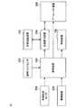
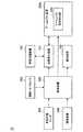
まず、図1〜図4を参照して、本発明の実施形態に係る車両のアームレスト制御システム10の概略構成について説明する。図1は、本実施形態に係るアームレスト制御システム10の概略構成の一例を示す模式図である。図1に示したように、アームレスト制御システム10は、送風吸引装置104と、車室空調装置106と、報知装置108と、アームレスト装置200と、操舵トルクセンサ302と、車両状態センサ304と、撮像装置306と、制御装置400と、を備える。本実施形態に係るアームレスト制御システム10は、自動運転モードと手動運転モードとを切り替え可能な車両に適用し得る。<1. Configuration of armrest control system>
First, with reference to FIGS. 1-4, schematic structure of the
送風吸引装置104は、車両の各種装置への空気の供給及び各種装置からの空気の吸引を行う。送風吸引装置104は、車室空調装置106及びアームレスト装置200のそれぞれと、空気が通過可能な通風路を介して接続されている。送風吸引装置104により車室空調装置106へ空気が供給されることにより、車室空調装置106による車室内の空調が行われる。また、送風吸引装置104によりアームレスト装置200へ空気が供給され又はアームレスト装置200から空気が吸引されることによって、アームレスト装置200のアームレストの内部の空気の圧力がドライバの腕を支持可能な程度の圧力に維持される。なお、アームレスト装置200の詳細については、後述する。アームレスト装置200への空気の供給及びアームレスト装置200からの空気の吸引において、送風吸引装置104は、制御装置400からの動作指示に基づいて駆動される。 The
送風吸引装置104は、車外又は車室内から空気を取り込み、取り込んだ空気を車室空調装置106及びアームレスト装置200のそれぞれへ供給する。また、アームレスト装置200から吸引された空気は、車外又は車室内へ送られる。なお、送風吸引装置104は、車室空調装置106又はアームレスト装置200と一体として構成されてもよい。 The
車室空調装置106は、送風吸引装置104から供給される空気を車室内へ送ることによって、車室内の空調を行う。具体的には、車室空調装置106は、車室内へ送風する空気の温度、方向及び流量の少なくとも1つを制御することによって、車室内の空調を行ってもよい。 The vehicle
報知装置108は、ドライバへ各種情報を報知する。例えば、報知装置108は、各種画面を表示することにより、ドライバへ各種情報を報知する。画面を表示する機能は、例えば、CRT(Cathode Ray Tube)ディスプレイ装置、液晶ディスプレイ(LCD)装置又はOLED(Organic Light Emitting Diode)装置により実現される。また、報知装置108は、音声を出力することにより、ドライバへ各種情報を報知してもよい。音声を出力する機能は、例えば、スピーカ又はハンドセットにより実現される。また、報知装置108は、振動を発生させることにより、ドライバへ各種情報を報知してもよい。振動を発生させる機能は、例えば、バイブレータ装置により実現される。報知装置108によるドライバへの各種情報の報知は、制御装置400からの動作指示に基づいて行われる。 The
アームレスト装置200は、ドライバの腕を支持するアームレストを含み、制御装置400からの動作指示に基づいて、アームレストの位置を調整する。アームレスト装置200によってアームレストの位置が調整されることによって、アームレストのドライバの腕を支持する支持部の位置が調整される。以下、アームレスト装置200の構成の詳細について、図2〜図4を参照して説明する。 The
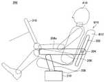
図2は、本実施形態に係るアームレスト装置200の構成の一例を示す説明図である。図2に示したように、アームレスト装置200は、ヒンジガイドレール202と、ヒンジ204と、アームレスト206と、アームレストピラー208と、アームレストピラー伸縮装置210と、を備える。 FIG. 2 is an explanatory diagram illustrating an example of a configuration of the
アームレスト206は、ステアリングホイール310が前方に設けられたドライバA10の座席B10の側部に設けられ、ドライバA10の腕を支持するために用いられる。アームレスト206の上面がドライバA10の腕を支持する支持部206aに相当し得る。アームレスト206の後端部は、ドライバA10の座席B10の背もたれ部B12の側面に沿って延設されたヒンジガイドレール202に設けられたヒンジ204と接続される。アームレスト206は、ヒンジ204を回転軸として回動自在に設けられる。ヒンジ204の位置は、アームレスト装置200の使用時においては固定されているが、ヒンジガイドレール202に沿って調整可能である。アームレスト206は中空となっており、アームレスト206の内部へヒンジ204を介して送風吸引装置104から供給される空気が送られる。それにより、アームレスト206の内部の空気圧がドライバA10の腕を支持可能な程度の圧力に維持される。 The
アームレスト206の前端部とアームレストピラー208の上端部は接続されている。アームレストピラー208は中空となっており、アームレストピラー208の内部とアームレスト206の内部は連通している。ゆえに、アームレスト206へ送られた空気はアームレストピラー208へ供給されるので、アームレストピラー208の内部の空気圧はドライバA10の腕を支持可能な程度の圧力に維持される。アームレストピラー208は、伸縮自在に設けられ、アームレストピラー伸縮装置210によって伸縮される。 The front end of the
図3は、本実施形態に係るアームレストピラー伸縮装置210の構成の一例を示す説明図である。図3に示したように、アームレストピラー伸縮装置210は、一対の無駆動ローラ212と、駆動ローラ214と、を備える。 FIG. 3 is an explanatory diagram showing an example of the configuration of the armrest pillar expansion /
アームレストピラー208の下部は一対の無駆動ローラ212により挟まれ、アームレストピラー208の無駆動ローラ212より下端側は駆動ローラ214と接続される。駆動ローラ214が回転することによって、アームレストピラー208の下部の駆動ローラ214により巻き取られる量が調整される。それにより、アームレストピラー208の無駆動ローラ212より上方へ延在する部分の長さが調整されるので、アームレストピラー208と接続されたアームレスト206がヒンジ204を回転軸として回動する。よって、アームレスト206の位置が調整される。例えば、図3に示したように、駆動ローラ214をアームレストピラー208の下部の巻き取られる量が減少するように回転させると、アームレストピラー208の無駆動ローラ212より上方へ延在する部分の長さが長くなる。よって、アームレスト206の位置を上昇させることができる。駆動ローラ214は、制御装置400からの動作指示に基づいて駆動される。駆動ローラ214の駆動は、例えば、電動モータにより実現される。 The lower part of the
また、アームレストピラー208の無駆動ローラ212より上方へ延在する部分の長さが長くなる場合には、送風吸引装置104によりアームレストピラー208の内部へ空気が供給される。一方、アームレストピラー208の無駆動ローラ212より上方へ延在する部分の長さが短くなる場合には、送風吸引装置104によりアームレストピラー208の内部から空気が吸引される。それにより、アームレスト206及びアームレストピラー208の内部の空気圧がドライバA10の腕を支持可能な程度の圧力に維持される。 In addition, when the length of the portion of the
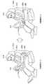
図4は、本実施形態に係るアームレスト206の基準位置の調整の一例を示す説明図である。ヒンジ204の位置をヒンジガイドレール202に沿って調整し、かつ、アームレストピラー208の伸縮量を調整することによって、アームレスト206の基準位置を調整することが可能である。図4では、一例として、ドライバA10の自動運転モードにおける姿勢として設定される安楽姿勢に対応するアームレスト206の位置を基準位置として調整する例が示されている。それにより、ドライバA10の体格や、ステアリングの位置に応じて適切な位置にアームレスト206の基準位置を調整することができる。以下、図1に戻り、本実施形態に係るアームレスト制御システム10の説明を続ける。 FIG. 4 is an explanatory diagram illustrating an example of adjustment of the reference position of the
操舵トルクセンサ302は、ドライバA10によるステアリング操作における操舵トルクを検出し、検出結果を制御装置400へ出力する。 The
車両状態センサ304は、車両の各種状態量を検出し、検出結果を制御装置400へ出力する。具体的には、車両状態センサ304により検出される車両の各種状態量は、車両の運転モードを判定するための状態量である。より具体的には、車両の各種状態量は、運転モードを切り替えるための図示しないスイッチのドライバA10による切り替え状態を示す状態量を含む。また、車両の各種状態量は、自動運転モードにおける自動運転制御に用いられる状態量を含む。自動運転制御に用いられる状態量は、例えば、温度、車速、ヨーレート及び車両に対する車線の相対位置を示す状態量の少なくとも1つを含んでもよい。 The
撮像装置306は、CCDセンサ、CMOSセンサ等の撮像素子を有して構成され、車室内を撮像し、撮像処理によって得られた画像に映る対象物を認識することができる。例えば、撮像装置306は、得られた画像に基づいて、ドライバA10の周囲の物体とドライバA10の手との位置関係を画像情報として認識することができる。撮像装置306によって得られた情報は、制御装置400へ出力される。 The
制御装置400は、演算処理装置であるCPU(Central Processing Unit)、CPUが使用するプログラムや演算パラメータ等を記憶する記憶素子であるROM(Read Only Memory)、CPUの実行において使用するプログラムや、その実行において適宜変化するパラメータ等を一時記憶する記憶素子であるRAM(Random Access Memory)等で構成される。 The
制御装置400は、アームレスト制御システム10を構成する各装置の動作を制御する。具体的には、制御装置400は、制御対象である各アクチュエータに対して電気信号を用いて動作指示を行う。より具体的には、制御装置400は、送風吸引装置104の駆動、報知装置108によるドライバA10への各種情報の報知及びアームレスト装置200のアームレストピラー伸縮装置210の駆動を制御する。また、制御装置400は、各センサから出力された情報を受信する。制御装置400は、CAN(Controller Area Network)通信を用いて各センサと通信を行ってもよい。なお、本実施形態に係る制御装置400が有する機能は複数の制御装置により分割されてもよく、その場合、当該複数の制御装置は、CAN等の通信バスを介して、互いに接続されてもよい。なお、制御装置400の詳細については、後述する。また、制御装置400及び送風吸引装置104は、アームレスト装置200に含まれてもよい。 The
<2.制御装置の構成>
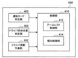
続いて、図5を参照して、本実施形態に係る制御装置400の機能構成について説明する。図5は、本実施形態に係る制御装置400の機能構成の一例を示す説明図である。図5に示したように、制御装置400は、運転モード判定部402と、ドライバ把持状態判定部404と、制御部410と、を含む。<2. Configuration of control device>
Subsequently, a functional configuration of the
(運転モード判定部)
運転モード判定部402は車両の運転モードの切り替え状態を判定し、判定結果を制御部410へ出力する。具体的には、運転モード判定部402は、運転モードの切り替えが開始したか否かを判定する。運転モードの切り替えは、運転モードの切り替えが開始した時点から切り替えが完了する時点までの間の数秒程度の切り替え移行期間において行われる。(Operation mode judgment part)
The driving
運転モード判定部402は、車両状態センサ304から出力される各種状態量に基づいて車両の運転モードの切り替えが開始したか否かを判定する。例えば、運転モード判定部402は、運転モードを切り替えるためのスイッチのドライバA10による切り替え状態を示す状態量に基づいて車両の運転モードの切り替えが開始したか否かを判定してもよい。具体的には、運転モード判定部402は、車両の運転モードが手動運転モードである場合に、自動運転モードへ切り替えるためにドライバA10が当該スイッチを切り替えたときに、手動運転モードから自動運転モードへの切り替えが開始したと判定してもよい。また、運転モード判定部402は、車両の運転モードが自動運転モードである場合に、手動運転モードへ切り替えるためにドライバA10が当該スイッチを切り替えたときに、自動運転モードから手動運転モードへの切り替えが開始したと判定してもよい。 The driving
運転モード判定部402は、自動運転モードにおける自動運転制御に用いられる温度、車速、ヨーレート、車両に対する車線の相対位置を示す状態量等の状態量に基づいて車両の運転モードの切り替えが開始したか否かを判定してもよい。例えば、車両の運転モードが自動運転モードである場合に、例えば、温度、車速、ヨーレート、車両に対する車線の相対位置を示す状態量等の状態量が異常値であるとき又は検出されなかったときに、制御装置400と異なる自動運転制御を行う制御装置によって自動運転モードから手動運転モードへの切り替えが行われる。 Whether the driving
具体的には、車線の白線が不鮮明であることにより車線を認識することができないために車両に対する車線の相対位置を示す状態量が検出されなかった場合に、自動運転制御を行う制御装置によって自動運転モードから手動運転モードへの切り替えが行われ得る。また、各種センサが故障していることにより当該センサによって検出されるべき状態量が検出されなかった場合に、自動運転制御を行う制御装置によって自動運転モードから手動運転モードへの切り替えが行われ得る。このような場合に、運転モード判定部402は、自動運転モードから手動運転モードへの切り替えが開始したと判定してもよい。なお、自動運転制御を行う制御装置と制御装置400は同一の制御装置であってもよい。 Specifically, if the state quantity indicating the relative position of the lane to the vehicle is not detected because the lane cannot be recognized because the white line of the lane is unclear, it is automatically detected by the control device that performs automatic driving control. Switching from the operation mode to the manual operation mode can be performed. In addition, when a state quantity that should be detected by the sensor is not detected due to a failure of various sensors, the automatic operation mode can be switched to the manual operation mode by the control device that performs the automatic operation control. . In such a case, the operation
また、運転モード判定部402は、自動運転モードから手動運転モードへの切り替えが開始したと判定した場合において、自動運転モードから手動運転モードへの切り替えがドライバA10の入力に応じて開始したか否かについて判定してもよい。 Further, when the operation
(ドライバ把持状態判定部)
ドライバ把持状態判定部404は、ドライバA10による物体の把持状態を判定し、判定結果を制御部410へ出力する。ドライバ把持状態判定部404は、具体的には、撮像装置306から出力される情報に基づいて、ドライバA10による物体の把持状態を判定する。例えば、ドライバ把持状態判定部404は、撮像装置306から出力される情報に基づいて、ドライバA10がステアリングホイール310を把持しているか否かを判定してもよい。具体的には、ドライバ把持状態判定部404は、ステアリングホイール310とドライバA10の手との位置関係に基づいて、ドライバA10がステアリングホイール310を把持しているか否かを判定してもよい。(Driver gripping state determination unit)
The driver gripping
ドライバ把持状態判定部404は、操舵トルクセンサ302から出力される操舵トルクを示す情報に基づいて、ドライバA10がステアリングホイール310を把持しているか否かを判定してもよい。具体的には、ドライバ把持状態判定部404は、操舵トルクが0より大きい場合に、ドライバA10がステアリングホイール310を把持していると判定してもよい。 The driver gripping
また、ステアリングホイール310に静電センサが設けられる場合、ドライバ把持状態判定部404は、当該静電センサにより検出される静電容量の変化に基づいて、ドライバA10がステアリングホイール310を把持しているか否かを判定してもよい。具体的には、ドライバ把持状態判定部404は、当該静電センサにより検出される静電容量の変化量がノイズ成分より大きい場合に、ドライバA10がステアリングホイール310を把持していると判定してもよい。 When the
ドライバ把持状態判定部404は、撮像装置306から出力される情報に基づいて、ドライバA10がステアリングホイール310と異なる物体を把持しているか否かを判定してもよい。例えば、ドライバ把持状態判定部404は、ステアリングホイール310と異なる物体とドライバA10の手との位置関係に基づいて、ドライバA10がステアリングホイール310と異なる物体を把持しているか否かを判定してもよい。ドライバA10がステアリングホイール310と異なる物体を把持していると判定された場合において、さらに、ドライバ把持状態判定部404は、ドライバA10の両手がステアリングホイール310と異なる物体を把持しているか否かを判定してもよい。 The driver gripping
また、車両にドライバA10の重量を検出する重量センサが設けられる場合、ドライバ把持状態判定部404は、当該重量センサにより検出される重量に基づいて、ドライバA10がステアリングホイール310と異なる物体を把持しているか否かを判定してもよい。ドライバA10が物体を手に持った場合に、当該物体の重量に応じて当該重量センサにより検出される重量が変化すると考えられる。ゆえに、ドライバ把持状態判定部404は、当該重量センサにより検出される重量の変化量がノイズ成分より大きい場合に、ドライバA10がステアリングホイール310と異なる物体を把持していると判定してもよい。 Further, when the vehicle is provided with a weight sensor that detects the weight of the driver A10, the driver gripping
なお、ドライバ把持状態判定部404が行うドライバA10による物体の把持状態の判定に用いられる各種閾値は、例えば、制御装置400の記憶素子に記憶され得る。 Various threshold values used for determining the gripping state of the object by the driver A10 performed by the driver gripping
(制御部)
制御部410は、アームレスト制御部412と、報知制御部414と、を含む。(Control part)
アームレスト制御部412は、アームレスト206の支持部206aの位置を制御する。具体的には、アームレスト制御部412は、アームレストピラー伸縮装置210及び送風吸引装置104へ動作指示を出力することにより、アームレスト206の位置を制御することによって、支持部206aの位置を制御する。 The
アームレスト制御部412は、運転モード判定部402による判定結果に基づいて、アームレスト206の支持部206aの位置を制御する。例えば、アームレスト制御部412は、運転モード判定部402により自動運転モードから手動運転モードへの切り替えが開始したと判定された時に、アームレストの支持部206aを、ステアリングホイール310へ近づくように移動させる。 The
また、アームレスト制御部412は、ドライバ把持状態判定部404による判定結果に基づいて、アームレスト206の支持部206aの位置を制御してもよい。例えば、アームレスト制御部412は、自動運転モードから手動運転モードへの切り替えが開始したと判定された時に、ドライバ把持状態判定部404によりドライバA10がステアリングホイール310を把持していると判定された場合には、アームレスト206の支持部206aを、ステアリングホイール310から遠ざかるように移動させてもよい。 Further, the
アームレスト制御部412は、自動運転モードから手動運転モードへの切り替えが開始したと判定された時に、ドライバ把持状態判定部404によりドライバA10の両手がステアリングホイール310と異なる物体を把持していると判定された場合には、アームレスト206の支持部206aの位置を保持してもよい。 When it is determined that the switching from the automatic operation mode to the manual operation mode is started, the
アームレスト制御部412は、自動運転モードから手動運転モードへの切り替えが開始したと判定された時に、ドライバ把持状態判定部404によりドライバA10の一方の手がステアリングホイール310と異なる物体を把持しており、他方の手はステアリングホイール310と異なる物体を把持していないと判定された場合には、アームレスト206の支持部206aのうち他方の手を支持する部分を、ステアリングホイール310へ近づくように移動させてもよい。例えば、アームレスト制御システム10において、ドライバA10の座席B10の左側方及び右側方にそれぞれドライバA10の左腕用及び右腕用のアームレスト206が設けられるように構成され得る。このような場合において、ドライバA10の右手はステアリングホイール310と異なる物体を把持し、左手はステアリングホイール310と異なる物体を把持していないときに、アームレスト制御部412は、左腕用のアームレスト206の支持部206aを、ステアリングホイール310へ近づくように移動させてもよい。 When it is determined that the switching from the automatic operation mode to the manual operation mode has started, the
アームレスト制御部412は、運転モード判定部402によりドライバA10の入力に応じて自動運転モードから手動運転モードへの切り替えが開始したと判定された時に、アームレスト206の支持部206aを、ステアリングホイール310から遠ざかるように移動させてもよい。 The
アームレスト制御部412は、運転モード判定部402により手動運転モードから自動運転モードへの切り替えが開始したと判定された時に、アームレスト206の支持部206aを、自動運転モードにおいてドライバA10の姿勢として設定される安楽姿勢に対応する位置へ移動させてもよい。 When the operation
また、アームレスト制御システム10がアームレスト206へ外部から負荷される力を検出するセンサを含む場合には、アームレスト制御部412は、当該センサから検出された力が所定の値より大きい場合に、アームレスト206の支持部206aの位置を保持してもよい。上記所定の値は、当該センサにより検出される力がノイズ成分よりも大きいか否かを判定し得る値に設定され得る。例えば、アームレスト206の移動中において、ドライバA10が意図的にアームレスト206の動きを止めようとした場合や、ドライバA10の衣類等がアームレスト206に引っかかった場合等において、アームレスト206が移動を続けることによる機器の破損や衣類等の破損を防止することができる。 Further, when the
報知制御部414は、ドライバA10への各種情報の報知装置108による報知を制御する。具体的には、報知制御部414は、動作指示を報知装置108へ出力することにより、ドライバA10への各種情報の報知装置108による報知を制御する。報知制御部414は、運転モード判定部402による判定結果及びドライバ把持状態判定部404による判定結果に基づいて、ドライバA10への各種情報の報知を制御する。例えば、報知制御部414は、自動運転モードから手動運転モードへの切り替えが開始したと判定された時に、ドライバ把持状態判定部404によりドライバA10の両手がステアリングホイール310と異なる物体を把持していると判定された場合には、手動運転モードへの切り替えが行われていることを示す情報を報知装置108に報知させる。 The
<3.動作>
続いて、図6〜10を参照して、本実施形態に係る制御装置400が行う処理の流れについて説明する。<3. Operation>
Subsequently, a flow of processing performed by the
(手動運転モードから自動運転モードへの切り替えにおける処理)
図6は、本実施形態に係る制御装置400が行う手動運転モードから自動運転モードへの切り替えにおける処理の流れの一例を示すフローチャートである。図6に示したように、手動運転モードから自動運転モードへの切り替えにおける処理では、まず、運転モード判定部402は、手動運転モードから自動運転モードへの切り替えが開始したか否かについて判定する(ステップS502)。運転モード判定部402により、手動運転モードから自動運転モードへの切り替えが開始したと判定されなかった場合(ステップS502/NO)、ステップS502の判定処理が繰り返される。一方、運転モード判定部402により、手動運転モードから自動運転モードへの切り替えが開始したと判定された場合(ステップS502/YES)、アームレスト制御部412は、アームレスト206の支持部206aをドライバA10の安楽姿勢に対応する位置へ移動させ(ステップS504)、図6に示した処理は終了する。(Processing in switching from manual operation mode to automatic operation mode)
FIG. 6 is a flowchart illustrating an example of a processing flow in switching from the manual operation mode to the automatic operation mode performed by the
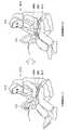
図7は、手動運転モードから自動運転モードへの切り替えにおける処理によるアームレスト206の位置調整の一例について説明するための説明図である。図7に示したように、手動運転モードにおいて、アームレスト206の位置はドライバA10によるステアリング操舵の妨げにならないような位置へ調整されている。具体的には、手動運転モードにおけるアームレスト206の位置は、自動運転モードにおけるドライバA10の安楽姿勢に対応するアームレスト206の位置と比較して、低い位置に設定される。運転モード判定部402により、手動運転モードから自動運転モードへの切り替えが開始したと判定されると、アームレスト206の位置はアームレスト制御部412からの動作指示に基づいて上昇し、アームレスト206の支持部206aは自動運転モードにおけるドライバA10の安楽姿勢に対応する位置へ調整される。それにより、自動運転モードにおいて、ドライバA10は、アームレスト206に腕を置き、安楽姿勢を取ることができる。 FIG. 7 is an explanatory diagram for explaining an example of position adjustment of the
(自動運転モードから手動運転モードへの切り替えにおける第1処理)
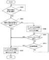
図8は、本実施形態に係る制御装置400が行う自動運転モードから手動運転モードへの切り替えにおける第1の処理の流れの一例を示すフローチャートである。図8に示したように、自動運転モードから手動運転モードへの切り替えにおける第1の処理では、まず、運転モード判定部402は、自動運転モードから手動運転モードへの切り替えが開始したか否かについて判定する(ステップS602)。運転モード判定部402により、自動運転モードから手動運転モードへの切り替えが開始したと判定されなかった場合(ステップS602/NO)、ステップS602の判定処理が繰り返される。一方、運転モード判定部402により、自動運転モードから手動運転モードへの切り替えが開始したと判定された場合(ステップS602/YES)、運転モード判定部402は、自動運転モードから手動運転モードへの切り替えがドライバA10の入力に応じて開始したか否かについて判定する(ステップS604)。(First process in switching from automatic operation mode to manual operation mode)
FIG. 8 is a flowchart illustrating an example of a flow of a first process in switching from the automatic operation mode to the manual operation mode performed by the
運転モード判定部402により、自動運転モードから手動運転モードへの切り替えがドライバA10の入力に応じて開始したと判定されなかった場合(ステップS604/NO)、アームレスト制御部412は、アームレスト206の支持部206aをステアリングホイール310へ近づくように移動させる(ステップS606)。次に、ドライバ把持状態判定部404は、ドライバA10がステアリングホイール310を把持しているか否かを判定する(ステップS608)。ドライバ把持状態判定部404により、ドライバA10がステアリングホイール310を把持していると判定された場合(ステップS608/YES)、アームレスト制御部412は、アームレスト206の支持部206aをステアリングホイール310から遠ざかるように移動させ(ステップS610)、図8に示した処理は終了する。 When the operation
図9は、自動運転モードから手動運転モードへの切り替えが自動で開始した場合の、自動運転モードから手動運転モードへの切り替えにおける第1の処理によるアームレスト206の位置調整の一例について説明するための説明図である。自動運転モードから手動運転モードへの切り替えが自動で開始した場合には、図8に示したステップS604の判定処理において、運転モード判定部402は、自動運転モードから手動運転モードへの切り替えがドライバA10の入力に応じて開始したと判定されない(ステップS604/NO)。 FIG. 9 is a diagram for explaining an example of position adjustment of the
図9に示したように、自動運転モードにおいて、アームレスト206の位置はドライバA10の安楽姿勢に対応する位置へ調整されている。図8に示したステップS604の判定処理において、自動運転モードから手動運転モードへの切り替えがドライバA10の入力に応じて開始したと判定されなかった場合、アームレスト206は、支持部206aがステアリングホイール310へ近づくように、動作指示に基づいて上昇する。それにより、アームレスト206に支持されているドライバA10の腕をステアリングホイール310を把持可能な位置へ誘導させることができる。よって、自動運転モードから手動運転モードへの切り替えが行われる間において、ドライバA10によるステアリングホイール310の把持を促すことができる。 As shown in FIG. 9, in the automatic operation mode, the position of the
次に、ドライバA10によってステアリングホイール310が把持されると、ドライバ把持状態判定部404により、ドライバA10がステアリングホイール310を把持していると判定される。そして、アームレスト206は、アームレスト206の支持部206aがステアリングホイール310から遠ざかるように降下し、アームレスト206の位置は、ドライバA10によるステアリング操舵の妨げにならないような位置へ調整される。それにより、手動運転モードにおいて、アームレスト206によりドライバA10によるステアリング操舵が妨げられることを防止することができる。 Next, when the
図8に示したように、ステップS608の判定処理において、ドライバ把持状態判定部404により、ドライバA10がステアリングホイール310を把持していると判定されなかった場合(ステップS608/NO)、ドライバ把持状態判定部404は、所定時間経過したか否かを判定する(ステップS612)。ここで、所定時間は、例えば、自動運転モードから手動運転モードへの切り替えの移行時間として設定される時間である。ドライバ把持状態判定部404により、所定時間経過したと判定された場合(ステップS612/YES)、アームレスト制御部412は、アームレスト206の支持部206aをステアリングホイール310から遠ざかるように移動させ(ステップS610)、図8に示した処理は終了する。それにより、ドライバA10がステアリングホイール310を把持していると判定されなかった場合であっても、手動運転モードにおいて、アームレスト206の位置をドライバA10によるステアリング操舵の妨げにならないような位置へ調整することができる。一方、ドライバ把持状態判定部404により、所定時間経過したと判定されなかった場合(ステップS612/NO)、ステップS608の判定処理へ戻る。 As shown in FIG. 8, in the determination process in step S608, when the driver gripping
また、ステップS604の判定処理において、運転モード判定部402により、自動運転モードから手動運転モードへの切り替えがドライバA10の入力に応じて開始したと判定された場合(ステップS604/YES)、アームレスト制御部412は、アームレスト206の支持部206aをステアリングホイール310から遠ざかるように移動させることによって、アームレスト206の位置をドライバA10によるステアリング操舵の妨げにならないような位置へ調整し(ステップS610)、図8に示した処理は終了する。 In the determination process of step S604, when the operation
図10は、自動運転モードから手動運転モードへの切り替えがドライバA10の入力に応じて開始した場合の、自動運転モードから手動運転モードへの切り替えにおける第1の処理によるアームレスト206の位置調整の一例について説明するための説明図である。図10に示したように、自動運転モードにおいて、アームレスト206の位置はドライバA10の安楽姿勢に対応する位置へ調整されている。自動運転モードから手動運転モードへの切り替えがドライバA10の入力に応じて開始した場合には、ドライバA10は自動運転モードから手動運転モードへの切り替えが行われていることを認識していると考えられる。ゆえに、ステアリングホイール310の把持を促すためにアームレスト206を上昇させる制御を省略することができる。よって、このような場合には、図10に示したように、アームレスト206は、支持部206aがステアリングホイール310から遠ざかるように、動作指示に基づいて降下し、アームレスト206の位置は、手動運転モードにおいてドライバA10によるステアリング操舵の妨げにならないような位置へ調整される。 FIG. 10 shows an example of the position adjustment of the
(自動運転モードから手動運転モードへの切り替えにおける第2処理)
図11は、本実施形態に係る制御装置400が行う自動運転モードから手動運転モードへの切り替えにおける第2の処理の流れの一例を示すフローチャートである。図11に示したように、自動運転モードから手動運転モードへの切り替えにおける第2の処理では、図8を参照して説明した第1の処理と比較して、ドライバA10がステアリングホイール310と異なる物体を把持しているか否かの判定及び当該判定の結果に基づくアームレスト206の制御が行われる点が異なる。(Second process in switching from automatic operation mode to manual operation mode)
FIG. 11 is a flowchart illustrating an example of the flow of the second process in switching from the automatic operation mode to the manual operation mode performed by the
図11に示したように、第2の処理では、ステップS604の判定処理において、自動運転モードから手動運転モードへの切り替えがドライバA10の入力に応じて開始したと判定されなかった場合(ステップS604/NO)、ドライバ把持状態判定部404は、ドライバA10がステアリングホイール310と異なる物体を把持しているか否かを判定する(ステップS702)。ドライバ把持状態判定部404により、ドライバA10がステアリングホイール310と異なる物体を把持していると判定されなかった場合(ステップS702/NO)、ステップS606の処理へ進む。一方、ドライバ把持状態判定部404により、ドライバA10がステアリングホイール310と異なる物体を把持していると判定された場合(ステップS702/YES)、ドライバ把持状態判定部404は、ドライバA10の両手がステアリングホイール310と異なる物体を把持しているか否かを判定する(ステップS704)。 As shown in FIG. 11, in the second process, when it is not determined in the determination process in step S604 that switching from the automatic operation mode to the manual operation mode has started in response to the input from the driver A10 (step S604). / NO), the driver gripping
ドライバ把持状態判定部404により、ドライバA10の両手が当該物体を把持していると判定された場合(ステップS704/YES)、アームレスト制御部412は、アームレスト206の支持部206aの位置を保持し、報知制御部414は、手動運転モードへの切り替えが行われていることを示す情報を報知装置108に報知させる(ステップS706)。ドライバA10の両手がステアリングホイール310と異なる物体を把持していると判定された場合には、ドライバA10はステアリングホイール310を把持することができない場合がある。また、このような場合に、アームレスト206の支持部206aを移動させる制御を行うと、ドライバA10が把持している当該物体又は当該物体に収容される物体の落下を生じるおそれがある。ゆえに、ステアリングホイール310の把持を促すためにアームレスト206を上昇させる制御を行わず、手動運転モードへの切り替えが行われていることを示す情報を報知する。それにより、ドライバA10が把持している当該物体又は当該物体に収容される物体の落下を防止しつつ、ドライバA10によるステアリングホイール310の把持を促すことができる。 When the driver gripping
そして、アームレスト制御部412は、所定時間経過したか否かを判定する(ステップS708)。ここで、所定時間は、例えば、自動運転モードから手動運転モードへの切り替えの移行時間として設定される時間である。アームレスト制御部412により、所定時間経過したと判定されなかった場合(ステップS708/NO)、ステップS708の判定処理が繰り返される。一方、アームレスト制御部412により、所定時間経過したと判定された場合(ステップS708/YES)、アームレスト制御部412は、アームレスト206の支持部206aをステアリングホイール310から遠ざかるように移動させ(ステップS610)、図11に示した処理は終了する。それにより、手動運転モードにおいて、アームレスト206によりドライバA10によるステアリング操舵が妨げられることを防止することができる。 Then, the
ステップS704の判定処理において、ドライバ把持状態判定部404により、ドライバA10の両手が当該物体を把持していると判定されなかった場合は(ステップS704/YES)、ドライバA10の一方の手が当該物体を把持しており、他方の手は当該物体を把持していないと判定された場合に相当する。このような場合に、アームレスト制御部412は、アームレスト206の支持部206aのうち当該物体を把持していない他方の手を支持する部分を、ステアリングホイール310へ近づくように移動させる(ステップS710)。そして、ステップS608の判定処理へ進む。それにより、一方の手がステアリングホイール310と異なる物体を把持している場合であっても、ドライバA10の他方の手に対応する腕をステアリングホイール310を把持可能な位置へ誘導させることができる。よって、自動運転モードから手動運転モードへの切り替えが行われる間において、ドライバA10によるステアリングホイール310の把持を促すことができる。 In the determination process of step S704, if the driver gripping
<4.応用例>
[4−1.第1の応用例]
続いて、図12〜図16を参照して、ドライバA10の意思を伴うハンドル操舵が行われるか否かの予測及び当該予測の結果に基づくアームレストの制御を行う第1の応用例について説明する。<4. Application example>
[4-1. First application example]
Next, with reference to FIGS. 12 to 16, a first application example for predicting whether or not steering wheel steering with the intention of the driver A <b> 10 is performed and controlling the armrest based on the prediction result will be described.
図12は、第1の応用例に係るアームレスト制御システム12の概略構成の一例を示す模式図である。図12に示したように、第1の応用例に係るアームレスト制御システム12では、図1を参照して説明したアームレスト制御システム10と比較して、アームレスト装置200aにアームレスト空気排出部250が備えられる点が異なる。 FIG. 12 is a schematic diagram illustrating an example of a schematic configuration of the armrest control system 12 according to the first application example. As shown in FIG. 12, in the armrest control system 12 according to the first application example, the armrest
アームレスト空気排出部250は、アームレスト206内に封入される空気を外部へ排出可能である。アームレスト空気排出部250によるアームレスト206内の空気の排出は、制御装置450によって制御される。アームレスト206内の空気が排出されると、アームレスト206は縮小する。 The armrest
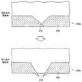
図13は、第1の応用例に係るアームレスト空気排出部250aの構成の一例を示す説明図である。図13に示したように、例えば、アームレスト空気排出部250aは、アームレスト206の内部と外部とを連通可能に設けられた切れ込み216を含む。切れ込み216は、アームレスト206の内部の空気の圧力が所定の圧力より低い場合には、閉鎖されている。一方、アームレスト206の内部の空気の圧力が所定の圧力より高くなると、切れ込み216が開放されるように構成される。例えば、送風吸引装置104によるアームレスト装置200からの空気の吸引を行わない状態で、図3に示した駆動ローラ214によりアームレストピラー208の下端部を巻き取らせることによって、アームレスト206の内部の空気の圧力が上昇し得る。そして、アームレスト206の内部の空気の圧力が所定の圧力より高くなると、切れ込み216が開放される。それにより、アームレスト206は縮小する。上記所定の圧力は、ドライバA10の意思を伴うハンドル操舵が行われると予測されない通常時において維持されるアームレスト206の内部の空気の圧力であるドライバA10の腕を支持可能な圧力より高く、かつ、駆動ローラ214の駆動力によって到達し得る圧力に設定される。 FIG. 13 is an explanatory diagram illustrating an example of the configuration of the armrest
図14は、他の例に係るアームレスト空気排出部250bの構成の一例を示す説明図である。図14に示したように、例えば、アームレスト空気排出部250bは、アームレスト206の一部に設けられた開口部218及びキャップ220と、を含む。開口部218は、アームレスト206の内部の空気の圧力が所定の圧力より低い場合には、キャップ220により閉鎖されている。一方、アームレスト206の内部の空気の圧力が所定の圧力より高くなると、キャップ220は外部へ放出され、開口部218が開放されるように構成される。例えば、送風吸引装置104によるアームレスト装置200からの空気の吸引を行わない状態で、図3に示した駆動ローラ214によりアームレストピラー208の下端部を巻き取らせることによって、アームレスト206の内部の空気の圧力が上昇し得る。そして、アームレスト206の内部の空気の圧力が所定の圧力より高くなると、キャップ220は外部へ放出され、開口部218が開放される。それにより、アームレスト206は縮小する。 FIG. 14 is an explanatory diagram illustrating an example of a configuration of an armrest
図15は、第1の応用例に係る制御装置450の機能構成の一例を示す説明図である。図15に示したように、第1の応用例に係る制御装置450は、図5を参照して説明した制御装置400と比較して、ドライバ操舵予測部452を備える点が異なる。 FIG. 15 is an explanatory diagram illustrating an example of a functional configuration of the
ドライバ操舵予測部452は、ドライバA10による所定の操舵が行われるか否かを予測する。具体的には、ドライバ操舵予測部452は、操舵トルクセンサ302から出力される操舵トルクを示す情報に基づいて、ドライバA10による所定の操舵が行われるか否かを予測してもよい。所定の操舵とは、ドライバA10の意思を伴うハンドル操舵であり、そのようなハンドル操舵が行われると予測された場合には、操作量の大きなハンドル操舵が行われる可能性が高いと考えられる。例えば、ドライバ操舵予測部452は、操舵トルクセンサ302から出力された操舵トルクが所定の閾値を超える場合に、ドライバA10による所定の操舵が行われると予測してもよい。所定の閾値は、ドライバA10の意思を伴う操作量の大きなハンドル操舵が行われるか否かを予測し得る値に設定される。 The driver
また、車両にステアリングホイール310の操舵角速度を検出する操舵角速度センサが設けられる場合、ドライバ操舵予測部452は、当該操舵角速度センサにより検出される操舵角速度に基づいて、ドライバA10による所定の操舵が行われるか否かを予測してもよい。例えば、ドライバ操舵予測部452は、当該操舵角速度センサにより検出される操舵角速度が所定の閾値を超える場合に、ドライバA10による所定の操舵が行われると予測してもよい。所定の閾値は、ドライバA10の意思を伴う操作量の大きなハンドル操舵が行われるか否かを予測し得る値に設定される。 When the vehicle is provided with a steering angular velocity sensor that detects the steering angular velocity of the
なお、ドライバ操舵予測部452が行うドライバA10による所定の操舵が行われるか否かの予測に用いられる各種閾値は、例えば、制御装置400の記憶素子に記憶され得る。 Note that various threshold values used for predicting whether or not predetermined steering by the driver A10 performed by the driver
アームレスト制御部412は、ドライバ操舵予測部452によりドライバA10による所定の操舵が行われると予測された時に、アームレスト206を縮小させることにより、アームレスト206の支持部206aをステアリングホイール310から遠ざかるように移動させる。具体的には、アームレスト制御部412は、ドライバ操舵予測部452によりドライバA10による所定の操舵が行われると予測された時に、アームレスト装置200からの空気の吸引を送風吸引装置104に行わせずに、アームレストピラー208の下端部が巻き取られるように駆動ローラ214を駆動させる。それにより、アームレスト空気排出部250によりアームレスト206内の空気が外部へ排出されるので、アームレスト206が縮小する。 The
図16は、第1の応用例に係る制御装置450の処理によるアームレスト206の位置調整の一例について説明するための説明図である。図16では、アームレスト206の下部の後端側に図13を参照して説明したアームレスト空気排出部250aが設けられる例が示されている。図16に示したように、アームレスト206の位置が移動している状態において、ドライバ操舵予測部452によりドライバA10による所定の操舵が行われると予測された場合、アームレスト制御部412は、アームレスト206を縮小させる。それにより、アームレスト206が速やかに降下し、アームレスト206の位置はドライバA10によるステアリング操舵の妨げにならないような位置へ速やかに調整される。ゆえに、ドライバA10の意思を伴う操作量の大きなハンドル操舵が行われる可能性の高い場合において、アームレスト206によってドライバA10によるステアリング操舵が妨げられることを速やかに防止することができる。 FIG. 16 is an explanatory diagram for explaining an example of position adjustment of the
第1の応用例に係る制御装置450によるドライバA10による所定の操作が行われるか否かの予測及び当該予測の結果に基づくアームレストの制御は、例えば、図7又は図9を参照して説明したアームレスト206の上昇時に行われてもよい。また、当該予測及び当該予測の結果に基づくアームレストの制御は、図9又は図10を参照して説明したアームレスト206の降下時に行われてもよい。 The prediction as to whether or not the predetermined operation by the driver A10 by the
なお、アームレスト206を縮小させる機構は、上述したアームレスト空気排出部250による例に限定されない。例えば、火薬により生じる熱又は衝撃若しくは薬品による溶解を利用してアームレスト206の一部を穿孔することにより、アームレスト206内の空気を排出する機構が適用されてもよい。また、アームレスト206の一部にアームレスト206の内部と外部とを連通可能なファスナーが設けられる場合、電動アクチュエータを利用してファスナーを開放することにより、アームレスト206内の空気を排出する機構が適用されてもよい。 The mechanism for reducing the
[4−2.第2の応用例]
続いて、図17を参照して、ドライバA10の覚醒度が低下状態であるか否かの判定及び当該判定の結果に基づくアームレストの制御を行う第2の応用例について説明する。[4-2. Second application example]
Next, with reference to FIG. 17, a second application example will be described in which it is determined whether or not the awakening level of the driver A10 is in a lowered state and the armrest is controlled based on the result of the determination.
図17は、第2の応用例に係る制御装置470の機能構成の一例を示す説明図である。図17に示したように、第2の応用例に係る制御装置470は、図5を参照して説明した制御装置400と比較して、ドライバ覚醒度判定部472を備える点が異なる。 FIG. 17 is an explanatory diagram illustrating an example of a functional configuration of the
ドライバ覚醒度判定部472は、ドライバA10の覚醒度が低下状態であるか否かを判定する。具体的には、ドライバ覚醒度判定部472は、撮像装置306から出力された情報に基づいて、ドライバA10の覚醒度が低下状態であるか否かを判定してもよい。ここで、撮像装置306は、撮像処理によって得られたドライバA10の顔の画像からドライバA10の覚醒度を認識することができるように構成され得る。ドライバ覚醒度判定部472は、撮像装置306により認識されたドライバA10の覚醒度に基づいて、ドライバA10の覚醒度が低下状態であるか否かを判定してもよい。低下状態は、具体的には、正常なハンドル操舵を行うことができない程度にドライバA10の覚醒度が低下している状態である。 The driver arousal
アームレスト制御部412は、ドライバ覚醒度判定部472によりドライバA10の覚醒度が低下状態であると判定された場合に、アームレスト206の支持部206aを往復運動させる。例えば、アームレスト制御部412は、ドライバ覚醒度判定部472によりドライバA10の覚醒度が低下状態であると判定された場合に、アームレスト206の支持部206aの上下動を繰り返す。それにより、ドライバA10の覚醒度が低下状態である場合に、ドライバA10の覚醒度を上昇させることができる。 The
<5.まとめ>
以上説明したように、本実施形態によれば、アームレスト制御部412は、運転モード判定部402により自動運転モードから手動運転モードへの切り替えが開始したと判定された時に、アームレスト206のドライバA10の腕を支持する支持部206aを、ステアリングホイール310へ近づくように移動させる。それにより、アームレスト206に支持されているドライバA10の腕をステアリングホイール310を把持可能な位置へ誘導させることができる。よって、自動運転モードから手動運転モードへの切り替えが行われる間において、ドライバA10によるステアリングホイール310の把持を促すことができる。<5. Summary>
As described above, according to the present embodiment, when the operation
上記では、アームレスト制御部412がアームレスト206の位置を制御することによって、アームレスト206の支持部206aの位置を制御する例について説明したが、本発明の技術的範囲は係る例に限定されない。例えば、アームレスト206は膨張及び収縮自在に構成されてもよく、その場合には、アームレスト206が膨張及び収縮することによって、アームレスト206の支持部206aの位置が調整され得る。このような場合には、アームレスト制御部412が、アームレスト206の膨張及び収縮を制御することによって、アームレスト206の支持部206aの位置を制御するように構成されてもよい。それにより、上述した本実施形態と同様の効果を得ることができる。 Although the example which controls the position of the
また、上記では、アームレスト206は中空となっており、アームレスト206の内部の空気圧がドライバA10の腕を支持可能な程度の圧力に維持される例について説明したが、本発明の技術的範囲は係る例に限定されない。例えば、アームレスト206は、ドライバA10の腕を支持可能であればよく、中実であってもよい。 In the above description, the
また、上記では、アームレストピラー208の伸縮によってアームレスト206の位置が調整される例について説明したが、本発明の技術的範囲は係る例に限定されない。例えば、アームレスト206と接続される図示しない電動アクチュエータが駆動することによってアームレスト206の位置が調整されるように構成されてもよい。 In the above description, the example in which the position of the
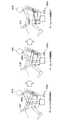
また、上記では、アームレスト206がドライバA10の座席B10の側部に設けられる例について説明したが、本発明の技術的範囲は係る例に限定されない。例えば、図18に示したように、アームレスト286は、ドライバA10の座席B10の背もたれ部B12の前側又は後側に設けられてもよい。係る場合には、手動運転モードにおいて、例えば、アームレスト286の少なくとも一部が、図18に示したように、ドライバA10の座席B10の背もたれ部B12の内部に収容される。また、手動運転モードから自動運転モードへの切り替えが行われた場合、アームレスト286の支持部286aがドライバA10の安楽姿勢に対応する位置へ移動するように、アームレスト286が移動する。そして、自動運転モードにおいて、アームレスト286の支持部286aは、例えば、図18に示したように、ドライバA10の安楽姿勢に対応する位置へ調整される。 Moreover, although the above demonstrated the example in which the
また、図19に示したように、アームレスト296は、運転時にドライバA10を座席B10へ保持するシートベルトB14に設けられてもよい。係る場合には、手動運転モードにおいて、例えば、アームレスト296は収縮した状態で、図19に示したように、シートベルトB14に沿って位置する。また、手動運転モードから自動運転モードへの切り替えが行われた場合、アームレスト296の支持部296aがドライバA10の安楽姿勢に対応する位置へ移動するように、アームレスト296が膨張する。そして、自動運転モードにおいて、アームレスト296の支持部296aは、例えば、図19に示したように、ドライバA10の安楽姿勢に対応する位置へ調整される。 As shown in FIG. 19, the
また、図13及び図14を参照して説明した第1の応用例において、アームレスト206内の空気を排出する機構を説明したが、アームレスト206を機械的に脱落させる機構を適用することによっても、第1の応用例と同様の効果を得られる。例えば、ドライバ操舵予測部452によりドライバA10による所定の操舵が行われると予測された場合に、アームレスト206をドライバA10の座席B10から機械的に脱落させることによって、アームレスト206によってドライバA10によるステアリング操舵が妨げられることを速やかに防止することができる。 Further, in the first application example described with reference to FIGS. 13 and 14, the mechanism for discharging the air in the
また、本明細書においてフローチャートを用いて説明した処理は、必ずしもフローチャートに示された順序で実行されなくてもよい。いくつかの処理ステップは、並列的に実行されてもよい。また、追加的な処理ステップが採用されてもよく、一部の処理ステップが省略されてもよい。 Further, the processing described using the flowchart in the present specification may not necessarily be executed in the order shown in the flowchart. Some processing steps may be performed in parallel. Further, additional processing steps may be employed, and some processing steps may be omitted.
以上、添付図面を参照しながら本発明の好適な実施形態について詳細に説明したが、本発明は係る例に限定されない。本発明の属する技術の分野における通常の知識を有する者であれば、特許請求の範囲に記載された技術的思想の範疇内において、各種の変更例又は応用例に想到し得ることは明らかであり、これらについても、当然に本発明の技術的範囲に属するものと了解される。 The preferred embodiments of the present invention have been described in detail above with reference to the accompanying drawings, but the present invention is not limited to such examples. It is obvious that a person having ordinary knowledge in the technical field to which the present invention pertains can make various modifications or application examples within the scope of the technical idea described in the claims. Of course, it is understood that these also belong to the technical scope of the present invention.
10、12 アームレスト制御システム
104 送風吸引装置
106 車室空調装置
108 報知装置
200、200a アームレスト装置
202 ヒンジガイドレール
204 ヒンジ
206、286、296 アームレスト
206a、286a、296a 支持部
208 アームレストピラー
210 アームレストピラー伸縮装置
212 無駆動ローラ
214 駆動ローラ
218 開口部
220 キャップ
250、250a、250b アームレスト空気排出部
302 操舵トルクセンサ
304 車両状態センサ
306 撮像装置
310 ステアリングホイール
400、450、470 制御装置
402 運転モード判定部
404 ドライバ把持状態判定部
410 制御部
412 アームレスト制御部
414 報知制御部
452 ドライバ操舵予測部
472 ドライバ覚醒度判定部DESCRIPTION OF
Claims (9)
Translated fromJapanese前記運転モード判定部により自動運転モードから手動運転モードへの切り替えが開始したと判定された時に、アームレストのドライバの腕を支持する支持部を、ステアリングホイールへ近づくように移動させるアームレスト制御部と、
を備えるアームレストの制御装置。An operation mode determination unit for determining a switching state of the vehicle operation mode capable of switching between the automatic operation mode and the manual operation mode;
An armrest control unit that moves the support unit supporting the arm of the driver of the armrest so as to approach the steering wheel when the operation mode determination unit determines that the switching from the automatic operation mode to the manual operation mode has started;
An armrest control device comprising:
前記アームレスト制御部は、自動運転モードから手動運転モードへの切り替えが開始したと判定された時に、前記ドライバ把持状態判定部により前記ドライバが前記ステアリングホイールを把持していると判定された場合には、前記支持部を前記ステアリングホイールから遠ざかるように移動させる、
請求項1に記載のアームレストの制御装置。A driver gripping state determination unit for determining a gripping state of an object by the driver;
When the armrest control unit determines that the driver is gripping the steering wheel when the driver gripping state determination unit determines that the switching from the automatic operation mode to the manual operation mode has started. , Moving the support part away from the steering wheel,
The armrest control device according to claim 1.
自動運転モードから手動運転モードへの切り替えが開始したと判定された時に、前記ドライバ把持状態判定部により前記ドライバの両手が前記ステアリングホイールと異なる物体を把持していると判定された場合には、前記アームレスト制御部は前記支持部の位置を保持し、前記報知制御部は手動運転モードへの切り替えが行われていることを示す情報を前記報知装置に報知させる、
請求項2に記載のアームレストの制御装置。A notification control unit that controls notification by the notification device of various information to the driver,
When it is determined that switching from the automatic operation mode to the manual operation mode has started, when it is determined by the driver gripping state determination unit that both hands of the driver are gripping an object different from the steering wheel, The armrest control unit holds the position of the support unit, and the notification control unit notifies the notification device of information indicating that switching to the manual operation mode is performed.
The armrest control device according to claim 2.
前記アームレスト制御部は、前記ドライバ操舵予測部により前記ドライバによる前記所定の操舵が行われると予測された時に、前記アームレストを縮小させることにより、前記支持部を前記ステアリングホイールから遠ざかるように移動させる、
請求項1〜5のいずれか一項に記載のアームレストの制御装置。A driver steering prediction unit that predicts whether or not predetermined steering by the driver is performed;
The armrest control unit moves the support unit away from the steering wheel by reducing the armrest when the driver steering prediction unit is predicted to perform the predetermined steering by the driver.
The control apparatus of the armrest as described in any one of Claims 1-5.
前記アームレスト制御部は、前記ドライバ覚醒度判定部により前記ドライバの覚醒度が低下状態であると判定された場合に、前記支持部を往復運動させる、
請求項1〜6のいずれか一項に記載のアームレストの制御装置。A driver arousal level determination unit that determines whether or not the driver's arousal level is in a reduced state;
The armrest control unit reciprocates the support unit when the driver arousal level determination unit determines that the driver arousal level is in a lowered state.
The control apparatus of the armrest as described in any one of Claims 1-6.
前記運転モード判定部により自動運転モードから手動運転モードへの切り替えが開始したと判定された時に、アームレストのドライバの腕を支持する支持部を、ステアリングホイールへ近づくように移動させるアームレスト制御部と、
を備える制御装置と、
前記制御装置からの動作指示に基づいて前記支持部の位置が調整されるアームレストと、
を備えるアームレスト装置。An operation mode determination unit for determining a switching state of the vehicle operation mode capable of switching between the automatic operation mode and the manual operation mode;
An armrest control unit that moves the support unit supporting the arm of the driver of the armrest so as to approach the steering wheel when the operation mode determination unit determines that the switching from the automatic operation mode to the manual operation mode has started;
A control device comprising:
An armrest in which the position of the support portion is adjusted based on an operation instruction from the control device;
An armrest device comprising:
Priority Applications (4)
| Application Number | Priority Date | Filing Date | Title |
|---|---|---|---|
| JP2015228686AJP6185543B2 (en) | 2015-11-24 | 2015-11-24 | Armrest control device and armrest device |
| US15/350,235US10245977B2 (en) | 2015-11-24 | 2016-11-14 | Armrest control device and armrest device |
| DE102016121871.5ADE102016121871A1 (en) | 2015-11-24 | 2016-11-15 | Armrest control and armrest device |
| CN201611025635.2ACN107031468B (en) | 2015-11-24 | 2016-11-17 | Handrail control device and handrail device |
Applications Claiming Priority (1)
| Application Number | Priority Date | Filing Date | Title |
|---|---|---|---|
| JP2015228686AJP6185543B2 (en) | 2015-11-24 | 2015-11-24 | Armrest control device and armrest device |
Related Child Applications (1)
| Application Number | Title | Priority Date | Filing Date |
|---|---|---|---|
| JP2017145773ADivisionJP6392948B2 (en) | 2017-07-27 | 2017-07-27 | Armrest control device and armrest device |
Publications (2)
| Publication Number | Publication Date |
|---|---|
| JP2017094899A JP2017094899A (en) | 2017-06-01 |
| JP6185543B2true JP6185543B2 (en) | 2017-08-23 |
Family
ID=58693665
Family Applications (1)
| Application Number | Title | Priority Date | Filing Date |
|---|---|---|---|
| JP2015228686AActiveJP6185543B2 (en) | 2015-11-24 | 2015-11-24 | Armrest control device and armrest device |
Country Status (4)
| Country | Link |
|---|---|
| US (1) | US10245977B2 (en) |
| JP (1) | JP6185543B2 (en) |
| CN (1) | CN107031468B (en) |
| DE (1) | DE102016121871A1 (en) |
Families Citing this family (27)
| Publication number | Priority date | Publication date | Assignee | Title |
|---|---|---|---|---|
| JP6629609B2 (en)* | 2016-01-28 | 2020-01-15 | 株式会社Subaru | Vehicle armrest control device |
| JP6368959B2 (en)* | 2016-05-19 | 2018-08-08 | 本田技研工業株式会社 | Vehicle control system, vehicle control method, and vehicle control program |
| JP6778516B2 (en)* | 2016-06-23 | 2020-11-04 | 本田技研工業株式会社 | Vehicle control system, vehicle control method, and vehicle control program |
| JP6769194B2 (en)* | 2016-09-08 | 2020-10-14 | トヨタ自動車株式会社 | Vehicle control device |
| JP6708089B2 (en)* | 2016-10-07 | 2020-06-10 | トヨタ紡織株式会社 | Vehicle seat |
| JP6760827B2 (en)* | 2016-11-24 | 2020-09-23 | 株式会社東海理化電機製作所 | Steering angle display device |
| US11273826B2 (en)* | 2017-01-23 | 2022-03-15 | Honda Motor Co., Ltd. | Vehicle control system, vehicle control method, and storage medium |
| JP6948919B2 (en)* | 2017-11-13 | 2021-10-13 | 日産自動車株式会社 | Armrest adjustment method and armrest device |
| JP7055661B2 (en)* | 2018-02-22 | 2022-04-18 | 本田技研工業株式会社 | Vehicle control unit |
| JP6655111B2 (en)* | 2018-03-09 | 2020-02-26 | 株式会社Subaru | Vehicle running control system |
| JP2019156247A (en)* | 2018-03-15 | 2019-09-19 | 本田技研工業株式会社 | Seat device |
| FR3092797B1 (en)* | 2019-02-19 | 2022-08-26 | Faurecia Interieur Ind | Adjustable armrest and assembly comprising such an armrest |
| US11858392B2 (en)* | 2019-03-01 | 2024-01-02 | Ts Tech Co., Ltd. | Vehicle seat and vehicle provided with vehicle seat |
| CN111845757A (en)* | 2019-04-30 | 2020-10-30 | 通用汽车环球科技运作有限责任公司 | Distracted Driving Elimination System |
| JP7147715B2 (en)* | 2019-08-07 | 2022-10-05 | トヨタ自動車株式会社 | Driving support device and driving support method |
| JP7226208B2 (en)* | 2019-09-17 | 2023-02-21 | トヨタ紡織株式会社 | Armrest device for sitting seat |
| JP7423948B2 (en)* | 2019-09-17 | 2024-01-30 | トヨタ紡織株式会社 | Armrest device for seating seats |
| CN110901643A (en)* | 2019-12-05 | 2020-03-24 | 大陆泰密克汽车系统(上海)有限公司 | Automatic driving active takeover system and method |
| JP7283430B2 (en)* | 2020-03-30 | 2023-05-30 | トヨタ自動車株式会社 | VEHICLE STEERING SYSTEM AND CONNECTION MECHANISM CHANGE METHOD |
| JP7010992B2 (en)* | 2020-04-03 | 2022-02-10 | 本田技研工業株式会社 | Vehicle control systems, vehicle control methods, and vehicle control programs |
| JP7517894B2 (en) | 2020-07-30 | 2024-07-17 | 株式会社Subaru | Vehicle seat control device |
| KR102405478B1 (en)* | 2020-09-24 | 2022-06-08 | 주식회사 서연이화 | Seat unit for vehicle |
| JP7342834B2 (en)* | 2020-10-20 | 2023-09-12 | トヨタ自動車株式会社 | vehicle |
| CN112644352B (en)* | 2021-01-20 | 2022-09-20 | 延锋汽车饰件系统有限公司 | Method, device and system for controlling seat armrest, seat, equipment and medium |
| CN113352957A (en)* | 2021-06-25 | 2021-09-07 | 广汽本田汽车有限公司 | Control method, system and device for automobile central control armrest and storage medium |
| CN113848013B (en)* | 2021-09-19 | 2024-06-25 | 九德智能装备(常州)有限公司 | Vehicle armrest torque testing equipment |
| JP2024005699A (en)* | 2022-06-30 | 2024-01-17 | パナソニックIpマネジメント株式会社 | Vehicle and armrest |
Family Cites Families (23)
| Publication number | Priority date | Publication date | Assignee | Title |
|---|---|---|---|---|
| DE4226747C1 (en)* | 1992-08-13 | 1993-12-16 | Daimler Benz Ag | Autopilot for motor vehicle also controlling driving seat position - returns seat automatically to driving position upon detection of driving situation which cannot be handled automatically |
| JP3239727B2 (en)* | 1995-12-05 | 2001-12-17 | トヨタ自動車株式会社 | Automatic driving control device for vehicles |
| CN201009773Y (en)* | 2007-03-20 | 2008-01-23 | 陈安伟 | Automatic safety drive seat |
| DE102007055088B4 (en)* | 2007-11-16 | 2013-03-07 | Airbus Operations Gmbh | Seat with a seat element, seat assembly and method for monitoring a seat |
| JP2009255778A (en) | 2008-04-17 | 2009-11-05 | Asmo Co Ltd | Arm rest device |
| JP5515771B2 (en)* | 2010-01-21 | 2014-06-11 | トヨタ自動車株式会社 | Armrest device |
| CN201619473U (en)* | 2010-04-09 | 2010-11-03 | 王德斌 | Safety protection device for automatic driver seat of automobile |
| US9751534B2 (en)* | 2013-03-15 | 2017-09-05 | Honda Motor Co., Ltd. | System and method for responding to driver state |
| MX345580B (en) | 2013-07-23 | 2017-02-07 | Nissan Motor | Vehicular drive assist device, and vehicular drive assist method. |
| US9073574B2 (en)* | 2013-11-20 | 2015-07-07 | Ford Global Technologies, Llc | Autonomous vehicle with reconfigurable interior |
| JP2016060277A (en)* | 2014-09-16 | 2016-04-25 | トヨタ自動車株式会社 | Information presenting device |
| GB2520842A (en) | 2014-12-04 | 2015-06-03 | Daimler Ag | Arm rest for a vehicle, in particular a passenger vehicle |
| JP6191633B2 (en)* | 2015-02-20 | 2017-09-06 | トヨタ自動車株式会社 | Driving assistance device |
| JP6582458B2 (en)* | 2015-03-13 | 2019-10-02 | トヨタ自動車株式会社 | Driving position control device |
| DE102015206501A1 (en)* | 2015-04-13 | 2016-10-13 | Bayerische Motoren Werke Aktiengesellschaft | Method for operating a vehicle and vehicle |
| JP2016203692A (en)* | 2015-04-16 | 2016-12-08 | トヨタ自動車株式会社 | In-cabin structure |
| US9573522B2 (en)* | 2015-04-29 | 2017-02-21 | Toyota Motor Engineering & Manufacturing North America, Inc. | Vehicle seat haptic indication of future planned driving maneuvers |
| EP3153346B1 (en)* | 2015-10-07 | 2019-09-25 | Volvo Car Corporation | A seat system for autonomous vehicles |
| JP6439647B2 (en)* | 2015-10-09 | 2018-12-19 | トヨタ自動車株式会社 | Crew attitude control device for vehicle |
| US20170291544A1 (en)* | 2016-04-12 | 2017-10-12 | Toyota Motor Engineering & Manufacturing North America, Inc. | Adaptive alert system for autonomous vehicle |
| GB2550610B (en)* | 2016-05-25 | 2019-11-20 | Ford Global Tech Llc | A steering wheel assembly |
| US9968023B2 (en)* | 2016-06-07 | 2018-05-15 | Cnh Industrial America Llc | Systems and methods for adjusting wheel spacing of an agricultural implement |
| DE102016116115A1 (en)* | 2016-08-30 | 2018-03-01 | Dr. Ing. H.C. F. Porsche Aktiengesellschaft | Ventilation system and ventilation method for a motor vehicle |
- 2015
- 2015-11-24JPJP2015228686Apatent/JP6185543B2/enactiveActive
- 2016
- 2016-11-14USUS15/350,235patent/US10245977B2/enactiveActive
- 2016-11-15DEDE102016121871.5Apatent/DE102016121871A1/enactivePending
- 2016-11-17CNCN201611025635.2Apatent/CN107031468B/enactiveActive
Also Published As
| Publication number | Publication date |
|---|---|
| JP2017094899A (en) | 2017-06-01 |
| DE102016121871A1 (en) | 2017-05-24 |
| CN107031468B (en) | 2021-01-15 |
| CN107031468A (en) | 2017-08-11 |
| US20170144568A1 (en) | 2017-05-25 |
| US10245977B2 (en) | 2019-04-02 |
Similar Documents
| Publication | Publication Date | Title |
|---|---|---|
| JP6185543B2 (en) | Armrest control device and armrest device | |
| JP5967309B2 (en) | Vehicle driving support apparatus and vehicle driving support method | |
| JP6239453B2 (en) | Electromagnetic damper | |
| US20170341648A1 (en) | Autonomous driving control apparatus, driving information output apparatus, footrest, autonomous driving control method, and driving information output method | |
| JP6704087B2 (en) | Occupant protection device | |
| JP6392948B2 (en) | Armrest control device and armrest device | |
| JP5302021B2 (en) | Sheet control apparatus, sheet control method, and sheet control program | |
| CN110997390B (en) | Method for operating a display device of a motor vehicle and motor vehicle | |
| CN107020977A (en) | Vehicle seat used control device | |
| US20160185259A1 (en) | Vehicle seat controller | |
| CN108367719B (en) | Electric Servo Drives for Motor Vehicles | |
| JPWO2022144975A5 (en) | ||
| JP2000211543A (en) | Vehicular driving supporting device | |
| JP6752756B2 (en) | Driver grip detection device | |
| JP2019141238A (en) | Balance training apparatus | |
| JP5543137B2 (en) | Voice control device for car wash machine | |
| JP6746307B2 (en) | Motion support device and method of controlling motion support device | |
| JP2016022864A (en) | Seat air blowing control device and seat air blowing control method | |
| US9939915B2 (en) | Control device and method for controlling functions in a vehicle, in particular a motor vehicle | |
| JP6233203B2 (en) | Electric vehicle motor control device | |
| WO2021033514A1 (en) | Seat control device | |
| JP2016074271A (en) | Inverted two-wheeled mobile system | |
| JP3979089B2 (en) | Mirror drive device for vehicle | |
| JP6245244B2 (en) | Pedestrian drive device and method for controlling walker drive device | |
| JP6519508B2 (en) | Potential adjustment device |
Legal Events
| Date | Code | Title | Description |
|---|---|---|---|
| TRDD | Decision of grant or rejection written | ||
| A01 | Written decision to grant a patent or to grant a registration (utility model) | Free format text:JAPANESE INTERMEDIATE CODE: A01 Effective date:20170627 | |
| A61 | First payment of annual fees (during grant procedure) | Free format text:JAPANESE INTERMEDIATE CODE: A61 Effective date:20170727 | |
| R150 | Certificate of patent or registration of utility model | Ref document number:6185543 Country of ref document:JP Free format text:JAPANESE INTERMEDIATE CODE: R150 | |
| R250 | Receipt of annual fees | Free format text:JAPANESE INTERMEDIATE CODE: R250 | |
| R250 | Receipt of annual fees | Free format text:JAPANESE INTERMEDIATE CODE: R250 | |
| R250 | Receipt of annual fees | Free format text:JAPANESE INTERMEDIATE CODE: R250 | |
| R250 | Receipt of annual fees | Free format text:JAPANESE INTERMEDIATE CODE: R250 | |
| R250 | Receipt of annual fees | Free format text:JAPANESE INTERMEDIATE CODE: R250 | |
| R250 | Receipt of annual fees | Free format text:JAPANESE INTERMEDIATE CODE: R250 |