JP6184220B2 - Radar system, radar apparatus and radar signal processing apparatus - Google Patents
Radar system, radar apparatus and radar signal processing apparatusDownload PDFInfo
- Publication number
- JP6184220B2 JP6184220B2JP2013153361AJP2013153361AJP6184220B2JP 6184220 B2JP6184220 B2JP 6184220B2JP 2013153361 AJP2013153361 AJP 2013153361AJP 2013153361 AJP2013153361 AJP 2013153361AJP 6184220 B2JP6184220 B2JP 6184220B2
- Authority
- JP
- Japan
- Prior art keywords
- signal
- radar
- unit
- observation
- interval
- Prior art date
- Legal status (The legal status is an assumption and is not a legal conclusion. Google has not performed a legal analysis and makes no representation as to the accuracy of the status listed.)
- Expired - Fee Related
Links
Images


Classifications
- G—PHYSICS
- G01—MEASURING; TESTING
- G01S—RADIO DIRECTION-FINDING; RADIO NAVIGATION; DETERMINING DISTANCE OR VELOCITY BY USE OF RADIO WAVES; LOCATING OR PRESENCE-DETECTING BY USE OF THE REFLECTION OR RERADIATION OF RADIO WAVES; ANALOGOUS ARRANGEMENTS USING OTHER WAVES
- G01S13/00—Systems using the reflection or reradiation of radio waves, e.g. radar systems; Analogous systems using reflection or reradiation of waves whose nature or wavelength is irrelevant or unspecified
- G01S13/02—Systems using reflection of radio waves, e.g. primary radar systems; Analogous systems
- G01S13/06—Systems determining position data of a target
- G01S13/08—Systems for measuring distance only
- G01S13/10—Systems for measuring distance only using transmission of interrupted, pulse modulated waves
- G01S13/22—Systems for measuring distance only using transmission of interrupted, pulse modulated waves using irregular pulse repetition frequency
- G01S13/225—Systems for measuring distance only using transmission of interrupted, pulse modulated waves using irregular pulse repetition frequency with cyclic repetition of a non-uniform pulse sequence, e.g. staggered PRF
- G—PHYSICS
- G01—MEASURING; TESTING
- G01S—RADIO DIRECTION-FINDING; RADIO NAVIGATION; DETERMINING DISTANCE OR VELOCITY BY USE OF RADIO WAVES; LOCATING OR PRESENCE-DETECTING BY USE OF THE REFLECTION OR RERADIATION OF RADIO WAVES; ANALOGOUS ARRANGEMENTS USING OTHER WAVES
- G01S13/00—Systems using the reflection or reradiation of radio waves, e.g. radar systems; Analogous systems using reflection or reradiation of waves whose nature or wavelength is irrelevant or unspecified
- G01S13/88—Radar or analogous systems specially adapted for specific applications
- G01S13/89—Radar or analogous systems specially adapted for specific applications for mapping or imaging
- G01S13/90—Radar or analogous systems specially adapted for specific applications for mapping or imaging using synthetic aperture techniques, e.g. synthetic aperture radar [SAR] techniques
- G01S13/904—SAR modes
- G01S13/9064—Inverse SAR [ISAR]
Landscapes
- Engineering & Computer Science (AREA)
- Remote Sensing (AREA)
- Radar, Positioning & Navigation (AREA)
- Physics & Mathematics (AREA)
- Computer Networks & Wireless Communication (AREA)
- General Physics & Mathematics (AREA)
- Electromagnetism (AREA)
- Radar Systems Or Details Thereof (AREA)
Description
Translated fromJapaneseこの発明は、目標の観測を行うレーダ装置と、レーダ装置による観測結果を示す信号を処理するレーダ信号処理装置とを備えたレーダシステム、レーダ装置およびレーダ信号処理装置に関するものである。 The present invention relates to a radar system, a radar apparatus, and a radar signal processing apparatus including a radar apparatus that performs target observation and a radar signal processing apparatus that processes a signal indicating an observation result of the radar apparatus.
合成開口画像レーダ(SAR:Synthetic Aperture Radar)の観測幅や、パルスドップラーレーダの探知距離を決定する要因の一つに、パルス繰返し間隔(PRI:Pulse Repetition Interval)がある。この理由の一つとして、PRIによって特定のレンジがブラインドレンジとなるため、このレンジを含まない範囲でレーダシステムを設計しなくてはならないことが挙げられる。
この課題に対し、PRIを不等間隔とすることによってブラインドレンジを拡散し、レーダの観測幅や探知距離を増大する方式が提案されている(例えば非特許文献1参照)。One of the factors that determine the observation width of a synthetic aperture image radar (SAR) and the detection distance of a pulse Doppler radar is a pulse repetition interval (PRI). One reason for this is that since a specific range becomes a blind range by PRI, the radar system must be designed in a range not including this range.
In response to this problem, a method has been proposed in which the blind range is diffused by setting the PRIs at unequal intervals to increase the radar observation width and detection distance (see, for example, Non-Patent Document 1).
しかしながら、PRIを不等間隔とすると、アジマス方向にフーリエ変換を行う際に、高速フーリエ変換(FFT:Fast Fourier Transform)が利用できない問題が発生する。そのため、その演算の高速化が課題となっている。 However, if the PRIs are set at unequal intervals, there is a problem that Fast Fourier Transform (FFT) cannot be used when performing Fourier transform in the azimuth direction. Therefore, speeding up the calculation has been an issue.
この発明は、上記のような課題を解決するためになされたもので、受信側においてフーリエ変換を行う際に高速フーリエ変換を利用することができ、演算の高速化を図ることができるレーダシステム、レーダ装置およびレーダ信号処理装置を提供することを目的としている。 The present invention has been made to solve the above-described problems, and a radar system that can use fast Fourier transform when performing Fourier transform on the receiving side, and can achieve high-speed computation. An object of the present invention is to provide a radar device and a radar signal processing device.
この発明に係るレーダシステムは、目標の観測を行うレーダ装置と、レーダ装置による観測結果を示す信号を処理するレーダ信号処理装置とを備え、レーダ装置は、観測を行うために送出する送信パルスのパルス繰返し間隔を、同一の波形による送信パルスの間隔は一定となるように周期性を残し、且つ、各送信パルス間の間隔は不等間隔とし、レーダ信号処理装置は、レーダ装置による観測結果を示す信号に対してレンジ圧縮を行うことで、周期性のある信号系列に分離する信号分離部と、信号分離部により分離された各信号系列を高速フーリエ変換により周波数領域に変換し、当該周波数領域に変換した信号系列を合成し、当該合成した信号を時間領域に戻す信号復元部と、信号復元部により得られた信号に対して画像再生を行うことで、再生画像を得る画像再生部とを備えたものである。A radar system according to the present invention includes a radar device that performs target observation and a radar signal processing device that processes a signal indicating an observation result by the radar device, and the radar device transmits a transmission pulse to be transmitted for observation. The pulse repetition interval remains periodicso that the interval between transmission pulses of thesame waveform is constant, and the interval between each transmission pulse is unequal, and the radar signal processing device uses the observation results from the radar device. By performing range compression on the indicated signal, a signal separation unit that separates the signal sequence with periodicity, and each signal sequence separated by the signal separation unit is converted into a frequency domain by fast Fourier transform, and the frequency domain A signal restoration unit that combines the signal sequence converted to, and returns the synthesized signal to the time domain, and performs image reproduction on the signal obtained by the signal restoration unit. It is obtained by an image reproduction unit to obtain a reproduced image.
また、この発明に係るレーダシステムは、目標の観測を行うレーダ装置と、レーダ装置による観測結果を示す信号を処理するレーダ信号処理装置とを備え、レーダ装置は、観測を行うために送出する送信パルスのパルス繰返し間隔を、同一の波形による送信パルスの間隔は一定となるように周期性を残し、且つ、各送信パルス間の間隔は不等間隔とし、レーダ信号処理装置は、レーダ装置による観測結果を示す信号に対してレンジ圧縮を行うことで、周期性のある信号系列に分離する信号分離部と、信号分離部により分離された各信号系列を高速フーリエ変換により周波数領域に変換し、当該周波数領域に変換した信号系列を合成する信号復元部と、信号復元部により得られた信号に基づいて、目標を検出する目標検出部と、目標検出部による検出結果に基づいて、目標までの距離および当該目標の移動速度を推定する距離/速度推定部とを備えたものである。In addition, a radar system according to the present invention includes a radar apparatus that performs target observation and a radar signal processing apparatus that processes a signal indicating an observation result by the radar apparatus, and the radar apparatus transmits a transmission for observation. The pulse repetition interval of the pulses remains periodicso that the intervals of transmission pulses with thesame waveform are constant, and the intervals between the transmission pulses are unequal, and the radar signal processing device is observed by the radar device. By performing range compression on the signal indicating the result, a signal separation unit that separates the signal sequence with periodicity, and each signal sequence separated by the signal separation unit is converted into the frequency domain by fast Fourier transform, A signal restoration unit that synthesizes the signal sequence converted into the frequency domain, a target detection unit that detects a target based on the signal obtained by the signal restoration unit, and a target detection unit. Based on the detection result, in which a distance / velocity estimation unit that estimates a distance and a moving speed of the target to the target.
また、この発明に係るレーダシステムは、目標の観測を行うレーダ装置と、レーダ装置による観測結果を示す信号を処理するレーダ信号処理装置とを備え、レーダ装置は、観測を行うために送出する送信パルスのパルス繰返し間隔を、同一の波形による送信パルスの間隔は一定となるように周期性を残し、且つ、各送信パルス間の間隔は不等間隔とし、送出された送信パルスに対して反射された信号を受信する複数の受信系統と、各受信系統により受信された信号に対してデジタルビーム形成を行うことで、周期性のある信号系列に分離するデジタルビーム形成部とを備え、レーダ信号処理装置は、デジタルビーム形成部により分離された各信号系列に対してレンジ圧縮を行うレンジ圧縮部と、レンジ圧縮部によりレンジ圧縮された各信号系列を高速フーリエ変換により周波数領域に変換し、当該周波数領域に変換した信号系列を合成し、当該合成した信号を時間領域に戻す信号復元部と、信号復元部により得られた信号に対して画像再生を行うことで、再生画像を得る画像再生部とを備えたものである。In addition, a radar system according to the present invention includes a radar apparatus that performs target observation and a radar signal processing apparatus that processes a signal indicating an observation result by the radar apparatus, and the radar apparatus transmits a transmission for observation. The pulse repetition interval of the pulses remains periodicso that the interval of the transmission pulses of thesame waveform is constant, and the intervals between the transmission pulses are unequal, and are reflected to the transmitted transmission pulses. Radar signal processing comprising a plurality of receiving systems for receiving received signals, and a digital beam forming unit that performs digital beam forming on the signals received by each receiving system, thereby separating the signals into periodic signal sequences. The apparatus includes a range compression unit that performs range compression on each signal sequence separated by the digital beam forming unit, and each signal system that is range compressed by the range compression unit. Is converted to the frequency domain by fast Fourier transform, the signal sequence converted to the frequency domain is synthesized, the signal restoration unit for returning the synthesized signal to the time domain, and the image reproduction for the signal obtained by the signal restoration unit And an image reproduction unit that obtains a reproduction image.
この発明によれば、上記のように構成したので、受信側においてフーリエ変換を行う際に高速フーリエ変換を利用することができ、演算の高速化を図ることができる。 According to this invention, since it comprised as mentioned above, when performing a Fourier transform on the receiving side, a fast Fourier transform can be utilized and the speeding up of calculation can be achieved.
以下、この発明の実施の形態について図面を参照しながら詳細に説明する。
実施の形態1.
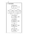
実施の形態1では、パルス繰返し周期(PRI)が周期性を残しつつ不等間隔となっているレーダシステム(SARシステム)について示す。図1はこの発明の実施の形態1に係るレーダシステムの構成を示す図である。
レーダシステムは、図1に示すように、レーダ装置(合成開口レーダ装置)1およびレーダ信号処理装置2から構成されている。Hereinafter, embodiments of the present invention will be described in detail with reference to the drawings.
In the first embodiment, a radar system (SAR system) in which the pulse repetition period (PRI) is non-uniformly spaced while maintaining periodicity will be described. 1 is a diagram showing a configuration of a radar system according to
As shown in FIG. 1, the radar system includes a radar device (synthetic aperture radar device) 1 and a radar
レーダ装置1は、合成開口を実現するため一定の速度で動きながら目標の観測を行うものである。このレーダ装置1は、図2に示すように、局部発振器101、信号生成部102、乗算器103、増幅器104、切換器105、アンテナ106、増幅器107、乗算器108およびA/Dコンバータ109から構成されている。 The
局部発振器101は、所定周波数の局部発振信号を出力するものである。
信号生成部102は、チャープパルスを生成するものである。この際、信号生成部102は、PRIを周期性を残しながら不等間隔とする。The
The
乗算器103は、局部発振器101から出力された局部発振信号を用いて、信号生成部102により生成された信号をアップコンバートするものである。
増幅器104は、乗算器103によりアップコンバートされた信号を増幅するものである。The
The
切換器105は、増幅器104とアンテナ106との間または増幅器107とアンテナ106との間を接続するものである。この切換器105は、増幅器104とアンテナ106との間を接続することで、増幅器104により増幅された信号をアンテナ106に出力し、また、増幅器107とアンテナ106との間を接続することで、アンテナ106により受信された信号を増幅器107に出力する。 The
アンテナ106は、切換器105を経由して増幅器104から出力された信号(送信パルス)を外部(目標)に送出し、また、外部からの送信パルスに対して反射された信号(エコー)を受信するものである。なお、アンテナ106は、レンジアンビギュイティを含むような広い観測幅で観測を行うものとする。 The
増幅器107は、アンテナ106により受信され、切換器105を経由して出力された信号を増幅するものである。
乗算器108は、局部発振器101から出力された局部発振信号を用いて、増幅器107により増幅された信号をダウンコンバートするものである。The
The
A/Dコンバータ109は、乗算器108によりダウンコンバートされた信号に対してA/D変換を行うことで、デジタル化するものである。このA/Dコンバータ109によりデジタル化された信号は生データ11としてレーダ信号処理装置2に出力される。 The A /
レーダ信号処理装置2は、レーダ装置1により得られた生データ11(観測結果を示す信号)を処理するものである。このレーダ信号処理装置2は、図3に示すように、信号分離部201、信号復元部202および画像再生部203から構成されている。 The radar
信号分離部201は、レーダ装置1により得られた生データ11に対してレンジ圧縮を行うことで、周期性のある信号系列に分離するものである。
信号復元部202は、信号分離部201により分離された各信号系列を高速フーリエ変換(FFT)により周波数領域に変換し、当該変換した各信号系列を合成し、当該合成した信号を逆高速フーリエ変換(IFFT)により時間領域に戻すものである。
画像再生部203は、信号復元部202により得られた信号に対して画像再生を行うことで、再生画像12を得るものである。The
The
The
次に、上記のように構成されたレーダシステムの処理手順について、図4〜9を参照しながら説明する。まず、レーダ装置1の処理手順について説明する。
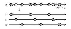
レーダ装置1の送信動作では、図4に示すように、まず、信号生成部102は、チャープパルスを生成する(ステップST401)。この際、信号生成部102は、図6に示すように、チャープレートが異なる3種類の波形(直交符号または当該直交符号に順ずる符号)を順番に用いる。また、このときのPRIは、図7(a)に示すように、周期性を残しながら不等間隔とする。このPRIを具体的に説明すると、図7(b)〜(d)に示すように同一の波形によるパルスの間隔は常に一定となるように周期性を残しつつ、パルス間の間隔はブラインドレンジが拡散するように不等間隔とする。Next, a processing procedure of the radar system configured as described above will be described with reference to FIGS. First, the processing procedure of the
In the transmission operation of the
次いで、乗算器103は、局部発振器101から出力された局部発振信号を用いて、信号生成部102により生成された信号をアップコンバートする(ステップST402)。
次いで、増幅器104は、乗算器103によりアップコンバートされた信号を増幅する(ステップST403)。Next,
Next,
次いで、アンテナ106は、増幅器104により増幅され切換器105を経由して出力された信号(送信パルス)を外部(目標)に送出する(ステップST404)。このとき送信パルスは、レンジアンビギュイティが発生するような広範囲にわたって照射されるものとする。 Next,
次に、レーダ装置1の受信動作では、まず、アンテナ106は、レンジアンビギュイティを含むような広い観測幅で観測を行い、ステップST404において送出した送信パルスに対するエコー(信号)を受信する(ステップST405)。 Next, in the receiving operation of the
次いで、増幅器107は、アンテナ106により受信され切換器105を経由して出力された信号を増幅する(ステップST406)。
次いで、乗算器108は、局部発振器101から出力された局部発振信号を用いて、増幅器107により増幅された信号をダウンコンバートする(ステップST407)。Next,
Next,
次いで、A/Dコンバータ109は、乗算器108によりダウンコンバートされた信号に対してA/D変換を行うことで、デジタル化する(ステップST408)。
次いで、A/Dコンバータ109は、デジタル化した信号を生データ11としてレーダ信号処理装置2に出力する(ステップST409)。Next, A /
Next, A /
次に、レーダ信号処理装置2の処理手順について説明する。
レーダ信号処理装置2の動作では、図5に示すように、まず、信号分離部201は、レーダ装置1により得られた生データ11を3つにコピーする(ステップST501)。
次いで、信号分離部201は、信号生成部102で用いたチャープレートが異なる3種類の波形のそれぞれの参照関数を用いて、コピーした3つの生データ11に対してレンジ圧縮を行うことで、周期性のある信号系列に分離する(ステップST502)。Next, the processing procedure of the radar
In the operation of the radar
Next, the
ここで、信号分離部201による信号分離処理を図8に示す。図8では、ある1点の目標からのエコーを示している。図8に示すエコーAは図7に示すパルスAに対するエコーであり、同様に、エコーBはパルスBに対するエコーであり、エコーCはパルスCに対するエコーである。そして、信号分離部201によりそれぞれのエコーを分離すると、送信側でPRIを周期性を残して不等間隔とした効果によって、図8(b)〜(d)に示すように、各エコーの系列が等間隔になる。この信号分離部201により分離された各信号系列(3つのエコーの系列)は信号復元部202に出力される。 Here, the signal separation processing by the
次いで、信号復元部202は、信号分離部201により分離された各信号系列(3つのエコーの系列)を、ヒット方向のFFTによりドップラー周波数領域の信号系列に変換する(ステップST503)。ここで、各信号系列がそれぞれ等間隔となっているため、FFTを用いることができる点が本発明の効果の一つである。 Next, the
次いで、信号復元部202は、ドップラー周波数領域に変換した信号系列(3つのエコーの周波数スペクトル)に対して復元アルゴリズム(例えば非特許文献2参照)を用いることで信号の合成を行い、エイリアシングのない広帯域信号のスペクトルを復元する(ステップST504)。 Next, the

次いで、信号復元部202は、復元した広帯域信号のスペクトルを、ヒット方向のIFFTにより、時間領域の信号に戻す(ステップST505)。
このように、信号復元部202によって、不等間隔の信号をドップラー周波数領域に変換して合成してエイリアシングのない広帯域信号を復元し、その後時間領域に戻すことで、補間を高速かつ高精度に行うことができる点が本発明の効果の一つである。Next, the
In this manner, the
なお、実施の形態1では、3つのパルスに対するエコーがすべて受信できるレンジに目標が存在することを仮定して説明を行った。しかし、レンジの位置によっては、拡散したブラインドレンジの影響を受け、一部のエコーが受信できない場合がある。このレンジの位置により、エコーが受信できない様相を図9に示す。図9(a)に示すレンジVでは3つのパルスのエコーがすべて受信できるのに対し、図9(b)〜(d)に示すレンジW,X,Yでは一部のエコーが受信できていない。これらのエコーの系列に対しても復元アルゴリズムを用いて広帯域信号に合成することは可能であるが、サンプリング点数が減っている分、観測帯域が狭くなる。したがって、アジマスのビーム幅は、レンジW,X,Yといったエコーの受信ができない場合のサンプリング点数に基づいて設計する必要がある。
また、本発明では、PRIに周期性を残しているため、図9(e)に示すレンジZのように、ブラインドレンジとなるレンジが存在する。しかしながら、このような場合であっても、PRIが等間隔である場合よりも、ブラインドレンジの間隔を延長することができ、観測幅を広げることができる点が本発明の効果の一つである。In the first embodiment, the description has been made on the assumption that the target exists in a range where all the echoes for the three pulses can be received. However, depending on the position of the range, some echoes may not be received due to the influence of the spread blind range. FIG. 9 shows a state in which an echo cannot be received depending on the position of this range. In the range V shown in FIG. 9A, echoes of all three pulses can be received, whereas in the ranges W, X, and Y shown in FIGS. 9B to 9D, some echoes cannot be received. . These echo sequences can also be synthesized into a wideband signal using a restoration algorithm, but the observation band is narrowed as the number of sampling points is reduced. Therefore, the beam width of azimuth needs to be designed based on the number of sampling points when echoes such as ranges W, X, and Y cannot be received.
In the present invention, since the periodicity remains in the PRI, there is a range that becomes a blind range, such as the range Z shown in FIG. However, even in such a case, one of the effects of the present invention is that the interval of the blind range can be extended and the observation width can be expanded as compared with the case where the PRI is equally spaced. .
次いで、画像再生部203は、信号復元部202により得られたレンジ圧縮済みの広帯域な信号に対して画像再生を行うことで、再生画像12を得る(ステップST506)。ここで、画像再生部203が用いる画像再生方法としては、非特許文献3,4に開示されるポーラフォーマット法や、チャープスケーリング法、レンジドップラー法、ω−k法などが挙げられる。なお、チャープスケーリング法を用いる場合には、レンジ圧縮の逆処理を行ってもよい。 Next, the
以上のように、この実施の形態1によれば、レーダ装置1は、観測を行うために送出する送信パルスのパルス繰返し間隔を、周期性を残しながら不等間隔とし、レーダ信号処理装置2は、レーダ装置1による観測結果を示す信号に対してレンジ圧縮を行うことで、周期性のある信号系列に分離する信号分離部201と、信号分離部201により分離された各信号系列を高速フーリエ変換により周波数領域に変換し、当該周波数領域に変換した信号系列を合成し、当該合成した信号を時間領域に戻す信号復元部202と、信号復元部202により得られた信号に対して画像再生を行うことで、再生画像12を得る画像再生部203とを備えたので、受信側においてフーリエ変換を行う際に高速フーリエ変換を利用することができ、演算の高速化・高精度化を図ることができる。 As described above, according to the first embodiment, the
実施の形態2.
実施の形態2では、PRIが周期性を残しつつ不等間隔となっており、また、レーダ装置1の受信側でデジタルビーム形成(DBF:Digital Beam Forming)を行うレーダシステム(SARシステム)について示す。図10はこの発明の実施の形態2に係るレーダ装置1の構成を示す図であり、図11はこの発明の実施の形態2に係るレーダ信号処理装置2の構成を示す図である。
図10に示す実施の形態2に係るレーダ装置1は、図2に示す実施の形態1に係るレーダ装置1から切換器105を削除し、アンテナ106、増幅器107、乗算器108およびA/Dコンバータ109を送信用のアンテナ106−N+1と複数の受信系統であるアンテナ106−1〜106−N、増幅器107−1〜107−N、乗算器108−1〜108−NおよびA/Dコンバータ109−1〜109−Nに変更し、デジタルビーム形成部110を追加したものである。その他の構成は同様であり、同一の符号を付してその説明を省略する。
また、図11に示す実施の形態2に係るレーダ信号処理装置2は、図3に示す実施の形態1に係るレーダ信号処理装置2から信号分離部201を削除し、レンジ圧縮部204を追加したものである。その他の構成は同様であり、同一の符号を付してその説明を省略する。
The
In addition, the radar
デジタルビーム形成部110は、A/Dコンバータ109−1〜109−Nによりデジタル化された信号に対してDBFを行うことで、周期性のある信号系列に分離するものである。このデジタルビーム形成部110により分離された各信号系列は生データ11−1〜11−3としてレーダ信号処理装置2に出力される。 The digital
レンジ圧縮部204は、レーダ装置1により得られた生データ11−1〜11−3に対してレンジ圧縮を行うものである。このレンジ圧縮部204によりレンジ圧縮された各信号系列は信号復元部202に出力される。
なお、特に区別する必要がない場合には、各符号のうち系統を示すハイフン以降の記載を省略する。The
In addition, when it is not necessary to distinguish in particular, description after the hyphen which shows a system | strain among each code | symbol is abbreviate | omitted.
次に、上記のように構成されたSARシステムの処理手順について、図12〜16を参照しながら説明する。まず、レーダ装置1の処理手順について説明する。なお、レーダ装置1は合成開口を実現するため一定の速度で動いているものとする。
レーダ装置1の送信動作では、図12に示すように、まず、信号生成部102は、チャープパルスを生成する(ステップST1201)。この際、各ヒットにおけるチャープパルスは同一でもよい。また、このときのPRIは、実施の形態1と同様、図14に示すように、周期性を残しながら不等間隔とする。Next, the processing procedure of the SAR system configured as described above will be described with reference to FIGS. First, the processing procedure of the
In the transmission operation of the
次いで、乗算器103は、局部発振器101から出力された局部発振信号を用いて、信号生成部102により生成された信号をアップコンバートする(ステップST1202)。
次いで、増幅器104は、乗算器103によりアップコンバートされた信号を増幅する(ステップST1203)。
次いで、アンテナ106−N+1は、増幅器104により増幅された信号(送信パルス13)を外部(目標)に送出する(ステップST1204)。Next,
Next,
Next, antenna 106-N + 1 transmits the signal (transmission pulse 13) amplified by
次に、レーダ装置1の受信動作では、まず、アンテナ106−1〜106−Nは、レンジアンビギュイティを含むような広い観測幅で観測を行い、ステップST1204において送出した送信パルス13に対する外部からのエコー(信号)を受信する(ステップST1205)。 Next, in the receiving operation of the
次いで、増幅器107−1〜107−Nは、対応するアンテナ106−1〜106−Nにより受信された信号を増幅する(ステップST1206)。
次いで、乗算器108−1〜108−Nは、局部発振器101から出力された局部発振信号を用いて、対応する増幅器107−1〜107−Nにより増幅された信号をダウンコンバートする(ステップST1207)。Next, amplifiers 107-1 to 107-N amplify signals received by corresponding antennas 106-1 to 106-N (step ST1206).
Next, multipliers 108-1 to 108-N downconvert the signals amplified by corresponding amplifiers 107-1 to 107-N using the local oscillation signal output from local oscillator 101 (step ST1207). .
次いで、A/Dコンバータ109−1〜109−Nは、対応する乗算器108−1〜108−Nによりダウンコンバートされた信号に対してA/D変換を行うことで、デジタル化する(ステップST1208)。 Next, A / D converters 109-1 to 109-N perform digitization by performing A / D conversion on the signals down-converted by corresponding multipliers 108-1 to 108-N (step ST1208). ).
次いで、デジタルビーム形成部110は、A/Dコンバータ109−1〜109−Nによりデジタル化された信号に対して、レンジアンビギュイティを抑圧してPRI毎のエコーを分離するようDBFを行うことで、受信ビーム14−1〜14−3を形成する(ステップST1209)。このデジタルビーム形成部110によるDBFによって得られた受信ビーム14−1〜14−3(信号)は、実施の形態1と同様に図15のように表される。また、ブラインドレンジの影響は、実施の形態1と同様に図16に示すような影響がある。
次いで、デジタルビーム形成部110は、形成した受信ビーム14−1〜14−3を生データ11−1〜11−3としてレーダ信号処理装置2に出力する(ステップST1210)。Next, the digital
Next, digital
次に、レーダ信号処理装置2の処理手順について説明する。
レーダ信号処理装置2の動作では、図13に示すように、まず、レンジ圧縮部204は、信号生成部102で用いたチャープレートの波形の参照関数を用いて、レーダ装置1により得られた生データ11−1〜11−3に対してレンジ圧縮を行う(ステップST1301)。このレンジ圧縮部204によりレンジ圧縮が行われた各信号系列は信号復元部202に出力される。以降の処理は実施の形態1と同様であり、その説明を省略する。Next, the processing procedure of the radar
In the operation of the radar
以上のように、この実施の形態2によれば、レーダ装置1の受信側でDBFを行うように構成したので、実施の形態1における効果に加え、送信パルスに直交波形を用いずにレンジアンビギュイティを抑圧しながら信号分離を行うことが可能となる。 As described above, according to the second embodiment, since the DBF is configured to be performed on the receiving side of the
実施の形態3.
実施の形態3では、PRIが周期性を残しつつ不等間隔となっているレーダシステム(パルスドップラーシステム)について示す。このパルスドップラーシステムは、実施の形態1,2に係るSARシステムと同様に、レーダ装置(パルスドップラーレーダ装置)1およびレーダ信号処理装置2から構成されている。ここで、実施の形態3に係るレーダ装置1は、図2,4に示す実施の形態1のレーダ装置1の構成・処理手順と同様であり、その説明を省略する。ただし、実施の形態3に係るレーダ装置1では合成開口を形成する必要がないため、移動体に搭載している状況ではない限り止っているものとする。
図17はこの発明の実施の形態3に係るレーダ信号処理装置2の構成を示す図である。図17に示す実施の形態3に係るレーダ信号処理装置2は、図3に示す実施の形態1に係るレーダ信号処理装置2から画像再生部203を削除して目標検出部205および距離/速度推定部206を追加し、信号復元部202を信号復元部202bに変更したものである。その他の構成は同様であり、同一の符号を付してその説明を省略する。Embodiment 3 FIG.
In the third embodiment, a radar system (pulse Doppler system) in which the PRIs are non-uniformly spaced while maintaining periodicity will be described. This pulse Doppler system includes a radar device (pulse Doppler radar device) 1 and a radar
FIG. 17 is a diagram showing the configuration of the radar
信号復元部202bは、信号分離部201により分離された各信号系列を高速フーリエ変換により周波数領域に変換し、当該変換した各信号を合成するものである。すなわち、実施の形態1における信号復元部202に対して、信号復元部202bでは合成した信号を時間領域に戻す処理を行わない。 The signal restoration unit 202b converts each signal sequence separated by the
目標検出部205は、信号復元部202bにより得られた信号に基づいて、目標を検出するものである。
距離/速度推定部206は、目標検出部205による検出結果に基づいて、目標までの距離および当該目標の移動速度を推定するものである。The target detection unit 205 detects a target based on the signal obtained by the signal restoration unit 202b.
The distance /
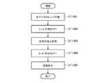
次に、上記のように構成されたレーダ信号処理装置2の処理手順について、図18を参照しながら説明する。
レーダ信号処理装置2の動作では、図18に示すように、まず、信号分離部201は、レーダ装置1により得られた生データ11を3つにコピーする(ステップST1801)。
次いで、信号分離部201は、信号生成部102で用いたチャーププレートが異なる3種類の波形のそれぞれの参照関数を用いて、コピーした3つの生データ11に対してレンジ圧縮を行うことで、周期性のある信号系列に分離する(ステップST1802)。この信号分離部201の動作は実施の形態1と同様である。Next, the processing procedure of the radar
In the operation of the radar
Next, the
次いで、信号復元部202bは、信号分離部201により分離された各信号系列(3つのエコーの系列)を、ヒット方向のFFTによりドップラー周波数領域の信号系列に変換する(ステップST1803)。
次いで、信号復元部202bは、ドップラー周波数領域に変換した各信号系列(3つのエコーの周波数スペクトル)に対して復元アルゴリズム(例えば非特許文献2参照)を用いることで信号の合成を行い、エイリアシングのない広帯域信号のスペクトルに復元する(ステップST1804)。Next, the signal restoration unit 202b converts each signal sequence (three echo sequences) separated by the
Next, the signal restoration unit 202b performs signal synthesis by using a restoration algorithm (for example, see Non-Patent Document 2) for each signal sequence (frequency spectrum of three echoes) converted into the Doppler frequency domain, and performs aliasing. The spectrum of the wideband signal is restored (step ST1804).
次いで、目標検出部205は、信号復元部202bにより復元された広帯域信号のスペクトルに対して雑音低減を目的とした移動平均処理を行う(ステップST1805)。
次いで、目標検出部205は、移動平均処理により得られたスペクトルに対して閾値判定を行うことで、目標を検出する(ステップST1806)。そして、目標検出部205は、検出した目標のレンジビン、ドップラー周波数ビンを目標分布情報として距離/速度推定部206に出力する。Next, target detection section 205 performs moving average processing for the purpose of noise reduction on the spectrum of the wideband signal restored by signal restoration section 202b (step ST1805).
Next, the target detection unit 205 detects a target by performing threshold determination on the spectrum obtained by the moving average process (step ST1806). Then, the target detection unit 205 outputs the detected target range bin and Doppler frequency bin to the distance /
次いで、距離/速度推定部206は、目標検出部205により得られた目標分布情報に基づいて、レンジビンから目標までの距離を推定し、ドップラー周波数ビンから目標の移動速度を推定する(ステップST1807)。 Next, distance /
以上のように、この実施の形態3によれば、SARシステムに代えてパルスドップラーシステムを用いても、実施の形態1と同様の効果を得ることができる。 As described above, according to the third embodiment, even if a pulse Doppler system is used instead of the SAR system, the same effect as in the first embodiment can be obtained.
なお、本願発明はその発明の範囲内において、各実施の形態の自由な組み合わせ、あるいは各実施の形態の任意の構成要素の変形、もしくは各実施の形態において任意の構成要素の省略が可能である。 In the present invention, within the scope of the invention, any combination of the embodiments, or any modification of any component in each embodiment, or omission of any component in each embodiment is possible. .
1 レーダ装置(合成開口レーダ装置、パルスドップラーレーダ装置)、2 レーダ信号処理装置、11 生データ、12 再生画像、13 送信パルス、14 受信ビーム、101 局部発振器、102 信号生成部、103 乗算器、104 増幅器、105 切換器、106 アンテナ、107 増幅器、108 乗算器、109 A/Dコンバータ、110 デジタルビーム形成部、201 信号分離部、202,202b 信号復元部、203 画像再生部、204 レンジ圧縮部、205 目標検出部、206 距離/速度推定部。 DESCRIPTION OF
Claims (8)
Translated fromJapanese前記レーダ装置は、前記観測を行うために送出する送信パルスのパルス繰返し間隔を、同一の波形による送信パルスの間隔は一定となるように周期性を残し、且つ、各送信パルス間の間隔は不等間隔とし、
前記レーダ信号処理装置は、
前記レーダ装置による観測結果を示す信号に対してレンジ圧縮を行うことで、前記周期性のある信号系列に分離する信号分離部と、
前記信号分離部により分離された各信号系列を高速フーリエ変換により周波数領域に変換し、当該周波数領域に変換した信号系列を合成し、当該合成した信号を時間領域に戻す信号復元部と、
前記信号復元部により得られた信号に対して画像再生を行うことで、再生画像を得る画像再生部とを備えた
ことを特徴とするレーダシステム。In a radar system including a radar apparatus that performs target observation and a radar signal processing apparatus that processes a signal indicating an observation result of the radar apparatus,
The radar device, the pulse repetition interval of the transmitted pulse to be sent in order to perform the observation,the distance between the transmission pulses with the same waveform leaving periodicityto beconstant,and the interval between each transmission pulse not Equally spaced,
The radar signal processing device is
A signal separator that separates the signal sequence having periodicity by performing range compression on the signal indicating the observation result by the radar device;
Each signal sequence separated by the signal separation unit is converted to a frequency domain by fast Fourier transform, a signal sequence converted to the frequency domain is synthesized, and a signal restoration unit that returns the synthesized signal to the time domain;
A radar system comprising: an image reproducing unit that obtains a reproduced image by performing image reproduction on the signal obtained by the signal restoration unit.
前記レーダ装置は、前記観測を行うために送出する送信パルスのパルス繰返し間隔を、同一の波形による送信パルスの間隔は一定となるように周期性を残し、且つ、各送信パルス間の間隔は不等間隔とし、
前記レーダ信号処理装置は、
前記レーダ装置による観測結果を示す信号に対してレンジ圧縮を行うことで、前記周期性のある信号系列に分離する信号分離部と、
前記信号分離部により分離された各信号系列を高速フーリエ変換により周波数領域に変換し、当該周波数領域に変換した信号系列を合成する信号復元部と、
前記信号復元部により得られた信号に基づいて、前記目標を検出する目標検出部と、
前記目標検出部による検出結果に基づいて、前記目標までの距離および当該目標の移動速度を推定する距離/速度推定部とを備えた
ことを特徴とするレーダシステム。In a radar system including a radar apparatus that performs target observation and a radar signal processing apparatus that processes a signal indicating an observation result of the radar apparatus,
The radar device, the pulse repetition interval of the transmitted pulse to be sent in order to perform the observation,the distance between the transmission pulses with the same waveform leaving periodicityto beconstant,and the interval between each transmission pulse not Equally spaced,
The radar signal processing device is
A signal separator that separates the signal sequence having periodicity by performing range compression on the signal indicating the observation result by the radar device;
Each signal sequence separated by the signal separation unit is converted into a frequency domain by fast Fourier transform, and a signal restoration unit that synthesizes the signal sequence converted into the frequency domain;
A target detection unit for detecting the target based on the signal obtained by the signal restoration unit;
A radar system comprising: a distance / speed estimation unit that estimates a distance to the target and a moving speed of the target based on a detection result by the target detection unit.
前記信号分離部は、前記レーダ装置により用いられた符号の直交性に基づいて、前記信号系列の分離を行う
ことを特徴とする請求項1または請求項2記載のレーダシステム。The radar device transmits a different chirp pulse at each pulse repetition interval using a different orthogonal code or a code following the orthogonal code as the transmission pulse,
The radar system according to claim 1, wherein the signal separation unit separates the signal series based on orthogonality of codes used by the radar apparatus.
前記レーダ装置は、前記観測を行うために送出する送信パルスのパルス繰返し間隔を、同一の波形による送信パルスの間隔は一定となるように周期性を残し、且つ、各送信パルス間の間隔は不等間隔とし、
前記送出された送信パルスに対して反射された信号を受信する複数の受信系統と、
前記各受信系統により受信された信号に対してデジタルビーム形成を行うことで、前記周期性のある信号系列に分離するデジタルビーム形成部とを備え、
前記レーダ信号処理装置は、
前記デジタルビーム形成部により分離された各信号系列に対してレンジ圧縮を行うレンジ圧縮部と、
前記レンジ圧縮部によりレンジ圧縮された各信号系列を高速フーリエ変換により周波数領域に変換し、当該周波数領域に変換した信号系列を合成し、当該合成した信号を時間領域に戻す信号復元部と、
前記信号復元部により得られた信号に対して画像再生を行うことで、再生画像を得る画像再生部とを備えた
ことを特徴とするレーダシステム。In a radar system including a radar apparatus that performs target observation and a radar signal processing apparatus that processes a signal indicating an observation result of the radar apparatus,
The radar device, the pulse repetition interval of the transmitted pulse to be sent in order to perform the observation,the distance between the transmission pulses with the same waveform leaving periodicityto beconstant,and the interval between each transmission pulse not Equally spaced,
A plurality of receiving systems for receiving signals reflected with respect to the transmitted transmission pulses;
A digital beam forming unit that separates the signal received by each receiving system into the periodic signal sequence by performing digital beam forming;
The radar signal processing device is
A range compression unit that performs range compression on each signal sequence separated by the digital beam forming unit;
A signal restoration unit that converts each signal sequence that has been range-compressed by the range compression unit into a frequency domain by fast Fourier transform, synthesizes the signal sequence converted into the frequency domain, and returns the synthesized signal to the time domain;
A radar system comprising: an image reproducing unit that obtains a reproduced image by performing image reproduction on the signal obtained by the signal restoration unit.
前記観測を行うために送出する送信パルスのパルス繰返し間隔を、同一の波形による送信パルスの間隔は一定となるように周期性を残し、且つ、各送信パルス間の間隔は不等間隔とする
ことを特徴とするレーダ装置。In a radar device that observes a target,
The pulse repetition interval of the transmission pulse transmitted to perform the observation should be periodicso that the transmission pulse interval of thesame waveform is constant, and the interval between the transmission pulses should be unequal. A radar device characterized by the above.
前記レーダ装置による観測結果を示す信号に対してレンジ圧縮を行うことで、前記周期性のある信号系列に分離する信号分離部と、
前記信号分離部により分離された各信号系列を高速フーリエ変換により周波数領域に変換し、当該周波数領域に変換した信号系列を合成し、当該合成した信号を時間領域に戻す信号復元部と、
前記信号復元部により得られた信号に対して画像再生を行うことで、再生画像を得る画像再生部と
を備えたことを特徴とするレーダ信号処理装置。The pulse repetition interval of the transmission pulse transmitted to perform the observation is left periodicso that the interval of the transmission pulse with thesame waveform is constant, and the interval between the transmission pulses is unequal, In a radar signal processing apparatus that processes a signal indicating an observation result by a radar apparatus that performs observation of
A signal separator that separates the signal sequence having periodicity by performing range compression on the signal indicating the observation result by the radar device;
Each signal sequence separated by the signal separation unit is converted to a frequency domain by fast Fourier transform, a signal sequence converted to the frequency domain is synthesized, and a signal restoration unit that returns the synthesized signal to the time domain;
A radar signal processing apparatus comprising: an image reproduction unit that obtains a reproduced image by performing image reproduction on the signal obtained by the signal restoration unit.
前記レーダ装置による観測結果を示す信号に対してレンジ圧縮を行うことで、前記周期性のある信号系列に分離する信号分離部と、
前記信号分離部により分離された各信号系列を高速フーリエ変換により周波数領域に変換し、当該周波数領域に変換した信号系列を合成する信号復元部と、
前記信号復元部により得られた信号に基づいて、前記目標を検出する目標検出部と、
前記目標検出部による検出結果に基づいて、前記目標までの距離および当該目標の移動速度を推定する距離/速度推定部と
を備えたことを特徴とするレーダ信号処理装置。The pulse repetition interval of the transmission pulse transmitted to perform the observation is left periodicso that the interval of the transmission pulse with thesame waveform is constant, and the interval between the transmission pulses is unequal, In a radar signal processing apparatus that processes a signal indicating an observation result by a radar apparatus that performs observation of
A signal separator that separates the signal sequence having periodicity by performing range compression on the signal indicating the observation result by the radar device;
Each signal sequence separated by the signal separation unit is converted into a frequency domain by fast Fourier transform, and a signal restoration unit that synthesizes the signal sequence converted into the frequency domain;
A target detection unit for detecting the target based on the signal obtained by the signal restoration unit;
A radar signal processing apparatus comprising: a distance / speed estimation unit configured to estimate a distance to the target and a moving speed of the target based on a detection result by the target detection unit.
前記デジタルビーム形成部により分離された各信号系列に対してレンジ圧縮を行うレンジ圧縮部と、
前記レンジ圧縮部によりレンジ圧縮された各信号系列を高速フーリエ変換により周波数領域に変換し、当該周波数領域に変換した信号系列を合成し、当該合成した信号を時間領域に戻す信号復元部と、
前記信号復元部により得られた信号に対して画像再生を行うことで、再生画像を得る画像再生部と
を備えたことを特徴とするレーダ信号処理装置。The pulse repetition interval of the transmission pulse transmitted for performing the observation, leavingthe periodicityso that the interval of the transmission pulse by thesame waveform is constant, and the interval between the transmission pulses is an unequal interval, A plurality of receiving systems that receive signals reflected in response to transmitted transmission pulses, and digital beam forming on the signals received by each receiving system, thereby separating the signal series with periodicity. In a radar signal processing device that includes a digital beam forming unit that processes a signal indicating an observation result by a radar device that performs target observation,
A range compression unit that performs range compression on each signal sequence separated by the digital beam forming unit;
A signal restoration unit that converts each signal sequence that has been range-compressed by the range compression unit into a frequency domain by fast Fourier transform, synthesizes the signal sequence converted into the frequency domain, and returns the synthesized signal to the time domain;
A radar signal processing apparatus comprising: an image reproduction unit that obtains a reproduced image by performing image reproduction on the signal obtained by the signal restoration unit.
Priority Applications (1)
| Application Number | Priority Date | Filing Date | Title |
|---|---|---|---|
| JP2013153361AJP6184220B2 (en) | 2013-07-24 | 2013-07-24 | Radar system, radar apparatus and radar signal processing apparatus |
Applications Claiming Priority (1)
| Application Number | Priority Date | Filing Date | Title |
|---|---|---|---|
| JP2013153361AJP6184220B2 (en) | 2013-07-24 | 2013-07-24 | Radar system, radar apparatus and radar signal processing apparatus |
Publications (2)
| Publication Number | Publication Date |
|---|---|
| JP2015025669A JP2015025669A (en) | 2015-02-05 |
| JP6184220B2true JP6184220B2 (en) | 2017-08-23 |
Family
ID=52490446
Family Applications (1)
| Application Number | Title | Priority Date | Filing Date |
|---|---|---|---|
| JP2013153361AExpired - Fee RelatedJP6184220B2 (en) | 2013-07-24 | 2013-07-24 | Radar system, radar apparatus and radar signal processing apparatus |
Country Status (1)
| Country | Link |
|---|---|
| JP (1) | JP6184220B2 (en) |
Cited By (1)
| Publication number | Priority date | Publication date | Assignee | Title |
|---|---|---|---|---|
| US20210190903A1 (en)* | 2018-11-02 | 2021-06-24 | Mitsubishi Electric Corporation | Radar apparatus and signal processing method |
Families Citing this family (2)
| Publication number | Priority date | Publication date | Assignee | Title |
|---|---|---|---|---|
| JP7257885B2 (en)* | 2019-06-11 | 2023-04-14 | 三菱電機株式会社 | Synthetic Aperture Radar System, Synthetic Aperture Radar Method, and Synthetic Aperture Radar Program |
| KR102289433B1 (en)* | 2020-05-29 | 2021-08-12 | 서울대학교산학협력단 | Image decoding apparatus based on squint sar and method of decoding image using the same |
Family Cites Families (8)
| Publication number | Priority date | Publication date | Assignee | Title |
|---|---|---|---|---|
| JPS61133885A (en)* | 1984-12-04 | 1986-06-21 | Nec Corp | Inter-pulse interference removing system for composite pulse radar |
| JPH0727021B2 (en)* | 1989-02-10 | 1995-03-29 | 三菱電機株式会社 | Synthetic aperture radar device |
| US5442359A (en)* | 1994-06-30 | 1995-08-15 | Unisys Corporation | Apparatus and method for mitigating range-doppler ambiguities in pulse-doppler radars |
| JP3792475B2 (en)* | 2000-03-30 | 2006-07-05 | 三菱電機株式会社 | Synthetic aperture radar apparatus and target image reproduction method |
| JP4630767B2 (en)* | 2005-08-29 | 2011-02-09 | 株式会社東芝 | Radar equipment |
| DE102005063417B4 (en)* | 2005-12-23 | 2021-01-07 | Airbus Defence and Space GmbH | Antenna for a high resolution synthetic aperture radar device |
| US7605744B1 (en)* | 2008-06-03 | 2009-10-20 | Vaisala Oyj | Method for extension of unambiguous range and velocity of a weather radar |
| JP2012002797A (en)* | 2010-05-17 | 2012-01-05 | Japan Radio Co Ltd | Radar apparatus |
- 2013
- 2013-07-24JPJP2013153361Apatent/JP6184220B2/ennot_activeExpired - Fee Related
Cited By (1)
| Publication number | Priority date | Publication date | Assignee | Title |
|---|---|---|---|---|
| US20210190903A1 (en)* | 2018-11-02 | 2021-06-24 | Mitsubishi Electric Corporation | Radar apparatus and signal processing method |
Also Published As
| Publication number | Publication date |
|---|---|
| JP2015025669A (en) | 2015-02-05 |
Similar Documents
| Publication | Publication Date | Title |
|---|---|---|
| US8686894B2 (en) | Radar imaging apparatus, imaging method, and program thereof | |
| JP5989258B2 (en) | Radar system and radar signal processing apparatus | |
| KR102204839B1 (en) | Apparatus and method of detecting target using radar | |
| JP5705057B2 (en) | Passive radar device | |
| JP5606097B2 (en) | Passive radar device | |
| Shah et al. | Step-frequency radar with compressive sampling (SFR-CS) | |
| JP2014119344A (en) | Synthetic aperture radar equipment | |
| US9568601B1 (en) | Successive-MFCW modulation for ultra-fast narrowband radar | |
| JP6184220B2 (en) | Radar system, radar apparatus and radar signal processing apparatus | |
| KR101125276B1 (en) | Method and Apparatus for Detecting Range and Velocity of Target by Using Radar and Computer Readable Recording Medium for Recording Program Therefor | |
| JP4962510B2 (en) | Target search signal generation method and target search device | |
| CN103364783A (en) | Moving target radial velocity non-fuzzy estimation method based on single-channel SAR (synthetic aperture radar) | |
| JP2012242288A (en) | Radar device | |
| JP6367140B2 (en) | Radar apparatus and radar signal processing method | |
| JP2010169671A (en) | Radar device | |
| WO2019009356A1 (en) | Radar device | |
| CN116736238A (en) | Target detection method and device based on CDMA and DDMA, radar equipment and storage medium | |
| JP5094447B2 (en) | Pulse radar equipment | |
| JP3641628B2 (en) | Automotive pulse radar equipment | |
| JP6861906B2 (en) | Radar device and signal processing method | |
| Guo et al. | Modified Omega-K algorithm for ground-based FMCW SAR imaging | |
| CN109597060B (en) | Radar speed measurement method and device | |
| JP7123670B2 (en) | Radar system and signal processing method | |
| JP6419330B2 (en) | Target detection apparatus and target detection method | |
| KR101645123B1 (en) | Method and apparatus for detecting distance and speed of target in high-resolution |
Legal Events
| Date | Code | Title | Description |
|---|---|---|---|
| A621 | Written request for application examination | Free format text:JAPANESE INTERMEDIATE CODE: A621 Effective date:20160107 | |
| A977 | Report on retrieval | Free format text:JAPANESE INTERMEDIATE CODE: A971007 Effective date:20161129 | |
| A131 | Notification of reasons for refusal | Free format text:JAPANESE INTERMEDIATE CODE: A131 Effective date:20161206 | |
| A521 | Written amendment | Free format text:JAPANESE INTERMEDIATE CODE: A523 Effective date:20170201 | |
| TRDD | Decision of grant or rejection written | ||
| A01 | Written decision to grant a patent or to grant a registration (utility model) | Free format text:JAPANESE INTERMEDIATE CODE: A01 Effective date:20170627 | |
| A61 | First payment of annual fees (during grant procedure) | Free format text:JAPANESE INTERMEDIATE CODE: A61 Effective date:20170725 | |
| R150 | Certificate of patent or registration of utility model | Ref document number:6184220 Country of ref document:JP Free format text:JAPANESE INTERMEDIATE CODE: R150 | |
| LAPS | Cancellation because of no payment of annual fees |